


MELSEC iQ-R
Motion Module
User's Manual (Network)
-RD78G4
-RD78G8
-RD78G16
-RD78G32
-RD78G64
-RD78GHV
-RD78GHW

WHEN USING A HUB WITH CC-Link IE TSN
WARNING
Indicates that incorrect handling may cause hazardous conditions, resulting in
death or severe injury.
CAUTION
Indicates that incorrect handling may cause hazardous conditions, resulting in
minor or moderate injury or property damage.
The dedicated TSN hub is required when modules on CC-Link IE TSN are configured in a star topology or hubs are
configured in a cascade topology.
Read the following carefully.
MELSEC iQ-R Motion Module User's Manual (Startup)
SAFETY PRECAUTIONS
(Read these precautions before using this product.)
Before using this product, please read this manual and the relevant manuals carefully and pay full attention to safety to handle
the product correctly.
The precautions given in this manual are concerned with this product only. Refer to the MELSEC iQ-R Module Configuration
Manual for a description of the PLC system safety precautions.
In this manual, the safety precautions are classified into two levels: " WARNING" and " CAUTION".
Under some circumstances, failure to observe the precautions given under " CAUTION" may lead to serious
consequences.
Observe the precautions of both levels because they are important for personal and system safety.
Make sure that the end users read this manual and then keep the manual in a safe place for future reference.
1

[Design Precautions]
WARNING
● Configure safety circuits external to the programmable controller to ensure that the entire system
operates safely even when a fault occurs in the external power supply or the programmable controller.
Failure to do so may result in an accident due to an incorrect output or malfunction.
(1) Emergency stop circuits, protection circuits, and protective interlock circuits for conflicting
operations (such as forward/reverse rotations or upper/lower limit positioning) must be configured
external to the programmable controller.
(2) When the programmable controller detects an abnormal condition, it stops the operation and all
outputs are:
• Turned off if the overcurrent or overvoltage protection of the power supply module is activated.
• Held or turned off according to the parameter setting if the self-diagnostic function of the CPU
module detects an error such as a watchdog timer error.
(3) All outputs may be turned on if an error occurs in a part, such as an I/O control part, where the
CPU module cannot detect any error. To ensure safety operation in such a case, provide a safety
mechanism or a fail-safe circuit external to the programmable controller. For a fail-safe circuit
example, refer to "General Safety Requirements" in the MELSEC iQ-R Module Configuration
Manual.
(4) Outputs may remain on or off due to a failure of a component such as a relay and transistor in an
output circuit. Configure an external circuit for monitoring output signals that could cause a
serious accident.
● In an output circuit, when a load current exceeding the rated current or an overcurrent caused by a
load short-circuit flows for a long time, it may cause smoke and fire. To prevent this, configure an
external safety circuit, such as a fuse.
● Configure a circuit so that the programmable controller is turned on first and then the external power
supply. If the external power supply is turned on first, an accident may occur due to an incorrect output
or malfunction.
● For the operating status of each station after a communication failure, refer to manuals relevant to the
network. Incorrect output or malfunction due to a communication failure may result in an accident.
2

[Design Precautions]
WARNING
● When connecting an external device with a CPU module or intelligent function module to modify data
of a running programmable controller, configure an interlock circuit in the program to ensure that the
entire system will always operate safely. For other forms of control (such as program modification,
parameter change, forced output, or operating status change) of a running programmable controller,
read the relevant manuals carefully and ensure that the operation is safe before proceeding. Improper
operation may damage machines or cause accidents.
● Especially, when a remote programmable controller is controlled by an external device, immediate
action cannot be taken if a problem occurs in the programmable controller due to a communication
failure. To prevent this, configure an interlock circuit in the program, and determine corrective actions
to be taken between the external device and CPU module in case of a communication failure.
● Do not write any data to the "system area" and "write-protect area" of the buffer memory in the
module. Also, do not use any "use prohibited" signals as an output signal from the CPU module to
each module. Doing so may cause malfunction of the programmable controller system. For the
"system area", "write-protect area", and the "use prohibited" signals, refer to the user's manual for the
module used.
● If a communication cable is disconnected, the network may be unstable, resulting in a communication
failure of multiple stations. Configure an interlock circuit in the program to ensure that the entire
system will always operate safely even if communications fail. Failure to do so may result in an
accident due to an incorrect output or malfunction.
● To maintain the safety of the programmable controller system against unauthorized access from
external devices via the network, take appropriate measures. To maintain the safety against
unauthorized access via the Internet, take measures such as installing a firewall.
● Configure safety circuits external to the programmable controller to ensure that the entire system
operates safely even when a fault occurs in the external power supply or the programmable controller.
Failure to do so may result in an accident due to an incorrect output or malfunction.
(1) Machine homing is controlled by two kinds of data: a homing direction and a homing speed.
Deceleration starts when the proximity dog signal turns on. If an incorrect homing direction is set,
motion control may continue without deceleration. To prevent machine damage caused by this,
configure an interlock circuit external to the programmable controller.
(2) When the module detects an error, the motion slows down and stops or the motion rapidly stops,
depending on the stop group setting in parameter. Set the parameter to meet the specifications of
a positioning control system. In addition, set the homing parameter and positioning data within the
specified setting range.
(3) Outputs may remain on or off, or become undefined due to a failure of a component such as an
insulation element and transistor in an output circuit, where the module cannot detect any error. In
a system that the incorrect output could cause a serious accident, configure an external circuit for
monitoring output signals.
● If safety standards (ex., robot safety rules, etc.,) apply to the system using the module, drive unit and
servomotor, make sure that the safety standards are satisfied.
● Construct a safety circuit externally of the module or drive unit if the abnormal operation of the module
or drive unit differs from the safety directive operation in the system.
3
[Design Precautions]
CAUTION
● Do not install the control lines or communication cables together with the main circuit lines or power
cables. Keep a distance of 100 mm or more between them. Failure to do so may result in malfunction
due to noise.
● During control of an inductive load such as a lamp, heater, or solenoid valve, a large current
(approximately ten times greater than normal) may flow when the output is turned from off to on.
Therefore, use a module that has a sufficient current rating.
● After the CPU module is powered on or is reset, the time taken to enter the RUN status varies
depending on the system configuration, parameter settings, and/or program size. Design circuits so
that the entire system will always operate safely, regardless of the time.
● Do not power off the programmable controller or reset the CPU module while the settings are being
written. Doing so will make the data in the flash ROM and SD memory card undefined. The values
need to be set in the buffer memory and written to the flash ROM and SD memory card again. Doing
so also may cause malfunction or failure of the module.
[Installation Precautions]
WARNING
● Shut off the external power supply (all phases) used in the system before mounting or removing the
module. Failure to do so may result in electric shock or cause the module to fail or malfunction.
[Installation Precautions]
CAUTION
● Use the programmable controller in an environment that meets the general specifications in the Safety
Guidelines included with the base unit. Failure to do so may result in electric shock, fire, malfunction,
or damage to or deterioration of the product.
● To mount a module, place the concave part(s) located at the bottom onto the guide(s) of the base unit,
push in the module, and fix it with screw(s). Incorrect interconnection may cause malfunction, failure,
or drop of the module.
● When using the programmable controller in an environment of frequent vibrations, fix the module with
a screw.
● Tighten the screws within the specified torque range. Undertightening can cause drop of the screw,
short circuit, or malfunction. Overtightening can damage the screw and/or module, resulting in drop,
short circuit, or malfunction.
● When using an extension cable, connect it to the extension cable connector of the base unit securely.
Check the connection for looseness. Poor contact may cause malfunction.
● When using an SD memory card, fully insert it into the SD memory card slot. Check that it is inserted
completely. Poor contact may cause malfunction.
● Securely insert an extended SRAM cassette or a battery-less option cassette into the cassette
connector of the CPU module. After insertion, close the cassette cover and check that the cassette is
inserted completely. Poor contact may cause malfunction.
● Do not directly touch any conductive parts of the module, SD memory card, extended SRAM cassette,
battery-less option cassette, or connector. Doing so can cause malfunction or failure of the module.
4

[Wiring Precautions]
WARNING
● Shut off the external power supply (all phases) used in the system before installation and wiring.
Failure to do so may result in electric shock or cause the module to fail or malfunction.
● After installation and wiring, attach a blank cover module (RG60) to each empty slot and an included
extension connector protective cover to the unused extension cable connector before powering on the
system for operation. Failure to do so may result in electric shock.
[Wiring Precautions]
CAUTION
● Individually ground the FG and LG terminals of the programmable controller with a ground resistance
of 100 ohms or less. Failure to do so may result in electric shock or malfunction.
● Use applicable solderless terminals and tighten them within the specified torque range. If any spade
solderless terminal is used, it may be disconnected when the terminal screw comes loose, resulting in
failure.
● Check the rated voltage and signal layout before wiring to the module, and connect the cables
correctly. Connecting a power supply with a different voltage rating or incorrect wiring may cause fire
or failure.
● Connectors for external devices must be crimped or pressed with the tool specified by the
manufacturer, or must be correctly soldered. Incomplete connections may cause short circuit, fire, or
malfunction.
● Securely connect the connector to the module. Poor contact may cause malfunction.
● Do not install the control lines or communication cables together with the main circuit lines or power
cables. Keep a distance of 100 mm or more between them. Failure to do so may result in malfunction
due to noise.
● Place the cables in a duct or clamp them. If not, dangling cables may swing or inadvertently be pulled,
resulting in malfunction or damage to the modules or cables.
In addition, the weight of the cables may put stress on modules in an environment of strong vibrations
and shocks.
Do not clamp the extension cables with the jacket stripped. Doing so may change the characteristics
of the cables, resulting in malfunction.
● Check the interface type and correctly connect the cable. Incorrect wiring (connecting the cable to an
incorrect interface) may cause failure of the module and external device.
● Tighten the terminal screws or connector screws within the specified torque range. Undertightening
can cause drop of the screw, short circuit, fire, or malfunction. Overtightening can damage the screw
and/or module, resulting in drop, short circuit, fire, or malfunction.
5
[Wiring Precautions]
CAUTION
● When disconnecting the cable from the module, do not pull the cable by the cable part. For the cable
with connector, hold the connector part of the cable. For the cable connected to the terminal block,
loosen the terminal screw. Pulling the cable connected to the module may result in malfunction or
damage to the module or cable.
● Prevent foreign matter such as dust or wire chips from entering the module. Such foreign matter can
cause a fire, failure, or malfunction.
● A protective film is attached to the top of the module to prevent foreign matter, such as wire chips,
from entering the module during wiring. Do not remove the film during wiring. Remove it for heat
dissipation before system operation.
● Programmable controllers must be installed in control panels. Connect the main power supply to the
power supply module in the control panel through a relay terminal block. Wiring and replacement of a
power supply module must be performed by qualified maintenance personnel with knowledge of
protection against electric shock. For wiring, refer to the MELSEC iQ-R Module Configuration Manual.
● For Ethernet cables to be used in the system, select the ones that meet the specifications in the user's
manual for the module used. If not, normal data transmission is not guaranteed.
[Startup and Maintenance Precautions]
WARNING
● Do not touch any terminal while power is on. Doing so will cause electric shock or malfunction.
● Correctly connect the battery connector. Do not charge, disassemble, heat, short-circuit, solder, or
throw the battery into the fire. Also, do not expose it to liquid or strong shock. Doing so will cause the
battery to produce heat, explode, ignite, or leak, resulting in injury and fire.
● Shut off the external power supply (all phases) used in the system before cleaning the module or
retightening the terminal screws, connector screws, or module fixing screws. Failure to do so may
result in electric shock.
6

[Startup and Maintenance Precautions]
CAUTION
● When connecting an external device with a CPU module or intelligent function module to modify data
of a running programmable controller, configure an interlock circuit in the program to ensure that the
entire system will always operate safely. For other forms of control (such as program modification,
parameter change, forced output, or operating status change) of a running programmable controller,
read the relevant manuals carefully and ensure that the operation is safe before proceeding. Improper
operation may damage machines or cause accidents.
● Especially, when a remote programmable controller is controlled by an external device, immediate
action cannot be taken if a problem occurs in the programmable controller due to a communication
failure. To prevent this, configure an interlock circuit in the program, and determine corrective actions
to be taken between the external device and CPU module in case of a communication failure.
● Do not disassemble or modify the modules. Doing so may cause failure, malfunction, injury, or a fire.
● Use any radio communication device such as a cellular phone or PHS (Personal Handy-phone
System) more than 25 cm away in all directions from the programmable controller. Failure to do so
may cause malfunction.
● Shut off the external power supply (all phases) used in the system before mounting or removing the
module. Failure to do so may cause the module to fail or malfunction.
● Tighten the screws within the specified torque range. Undertightening can cause drop of the
component or wire, short circuit, or malfunction. Overtightening can damage the screw and/or module,
resulting in drop, short circuit, or malfunction.
● After the first use of the product, do not perform each of the following operations more than 50 times
(IEC 61131-2/JIS B 3502 compliant).
Exceeding the limit may cause malfunction.
• Mounting/removing the module to/from the base unit
• Inserting/removing the extended SRAM cassette or battery-less option cassette to/from the
CPU module
• Mounting/removing the terminal block to/from the module
● After the first use of the product, do not insert/remove the SD memory card to/from the CPU module
more than 500 times. Exceeding the limit may cause malfunction.
● Do not touch the metal terminals on the back side of the SD memory card. Doing so may cause
malfunction or failure of the module.
● Do not touch the integrated circuits on the circuit board of an extended SRAM cassette or a batteryless option cassette. Doing so may cause malfunction or failure of the module.
● Do not drop or apply shock to the battery to be installed in the module. Doing so may damage the
battery, causing the battery fluid to leak inside the battery. If the battery is dropped or any shock is
applied to it, dispose of it without using.
● Startup and maintenance of a control panel must be performed by qualified maintenance personnel
with knowledge of protection against electric shock. Lock the control panel so that only qualified
maintenance personnel can operate it.
● Before handling the module, touch a conducting object such as a grounded metal to discharge the
static electricity from the human body. Failure to do so may cause the module to fail or malfunction.
7
[Startup and Maintenance Precautions]
CAUTION
● Before testing the operation, set a low speed value for the speed limit parameter so that the operation
can be stopped immediately upon occurrence of a hazardous condition.
● Confirm and adjust the program and each parameter before operation. Unpredictable movements
may occur depending on the machine.
● When using the absolute position system function, on starting up, and when the module or absolute
position motor has been replaced, always perform a homing.
● Before starting the operation, confirm the brake function.
● Do not perform a megger test (insulation resistance measurement) during inspection.
● After maintenance and inspections are completed, confirm that the position detection of the absolute
position detection function is correct.
● Lock the control panel and prevent access to those who are not certified to handle or install electric
equipment.
[Operating Precautions]
CAUTION
● When changing data and operating status, and modifying program of the running programmable
controller from an external device such as a personal computer connected to an intelligent function
module, read relevant manuals carefully and ensure the safety before operation. Incorrect change or
modification may cause system malfunction, damage to the machines, or accidents.
● Do not power off the programmable controller or reset the CPU module while the setting values in the
buffer memory are being written to the flash ROM in the module. Doing so will make the data in the
flash ROM and SD memory card undefined. The values need to be set in the buffer memory and
written to the flash ROM and SD memory card again. Doing so also may cause malfunction or failure
of the module.
● Note that when the reference axis speed is specified for interpolation operation, the speed of the
partner axis (2nd, 3rd, or 4th axis) may exceed the speed limit value.
● Do not go near the machine during test operations or during operations such as teaching. Doing so
may lead to injuries.
[Disposal Precautions]
CAUTION
● When disposing of this product, treat it as industrial waste.
● When disposing of batteries, separate them from other wastes according to the local regulations. For
details on battery regulations in EU member states, refer to the MELSEC iQ-R Module Configuration
Manual.
8

[Transportation Precautions]
CAUTION
● When transporting lithium batteries, follow the transportation regulations. For details on the regulated
models, refer to the MELSEC iQ-R Module Configuration Manual.
● The halogens (such as fluorine, chlorine, bromine, and iodine), which are contained in a fumigant
used for disinfection and pest control of wood packaging materials, may cause failure of the product.
Prevent the entry of fumigant residues into the product or consider other methods (such as heat
treatment) instead of fumigation. The disinfection and pest control measures must be applied to
unprocessed raw wood.
9

INTRODUCTION
Thank you for purchasing the Mitsubishi Electric MELSEC iQ-R series programmable controllers.
This manual describes the functions, programming, and troubleshooting of the relevant product listed below.
Before using this product, please read this manual and the relevant manuals carefully and develop familiarity with the
functions and performance of the MELSEC iQ-R series programmable controller to handle the product correctly.
When applying the program examples provided in this manual to an actual system, ensure the applicability and confirm that it
will not cause system control problems.
Please make sure that the end users read this manual.
Relevant products
RD78G4, RD78G8, RD78G16, RD78G32, RD78G64, RD78GHV, RD78GHW
Symbols used in this manual are shown below.
• [RD78GH]: Symbols indicating that it corresponds to only RD78GH
COMPLIANCE WITH EMC AND LOW VOLTAGE DIRECTIVES
Method of ensuring compliance
To ensure that Mitsubishi programmable controllers maintain EMC and Low Voltage Directives when incorporated into other
machinery or equipment, certain measures may be necessary. Please refer to one of the following manuals.
MELSEC iQ-R Module Configuration Manual
Safety Guidelines (This manual is included with the base unit.)
The CE mark on the side of the programmable controller indicates compliance with EMC and Low Voltage Directives.
Additional measures
To ensure that this product maintains EMC and Low Voltage Directives, please refer to one of the following manuals.
MELSEC iQ-R Module Configuration Manual
Safety Guidelines (This manual is included with the base unit.)
10

CONTENTS
WHEN USING A HUB WITH CC-Link IE TSN. . . . . . . . . . . . . . . . . . . . . . . . . . . . . . . . . . . . . . . . . . . . . . . . . . . . .1
SAFETY PRECAUTIONS . . . . . . . . . . . . . . . . . . . . . . . . . . . . . . . . . . . . . . . . . . . . . . . . . . . . . . . . . . . . . . . . . . . .1
INTRODUCTION. . . . . . . . . . . . . . . . . . . . . . . . . . . . . . . . . . . . . . . . . . . . . . . . . . . . . . . . . . . . . . . . . . . . . . . . . .10
COMPLIANCE WITH EMC AND LOW VOLTAGE DIRECTIVES . . . . . . . . . . . . . . . . . . . . . . . . . . . . . . . . . . . . .10
RELEVANT MANUALS . . . . . . . . . . . . . . . . . . . . . . . . . . . . . . . . . . . . . . . . . . . . . . . . . . . . . . . . . . . . . . . . . . . . .13
TERMS . . . . . . . . . . . . . . . . . . . . . . . . . . . . . . . . . . . . . . . . . . . . . . . . . . . . . . . . . . . . . . . . . . . . . . . . . . . . . . . . .14
FUTURE SUPPORT PLANNED . . . . . . . . . . . . . . . . . . . . . . . . . . . . . . . . . . . . . . . . . . . . . . . . . . . . . . . . . . . . . .16
CHAPTER 1 FUNCTIONS 17
1.1 Cyclic Transmission . . . . . . . . . . . . . . . . . . . . . . . . . . . . . . . . . . . . . . . . . . . . . . . . . . . . . . . . . . . . . . . . . . . . . 17
Communications using slave labels . . . . . . . . . . . . . . . . . . . . . . . . . . . . . . . . . . . . . . . . . . . . . . . . . . . . . . . . . . 17
1.2 Transient Transmission . . . . . . . . . . . . . . . . . . . . . . . . . . . . . . . . . . . . . . . . . . . . . . . . . . . . . . . . . . . . . . . . . . 18
Communications using the SLMP . . . . . . . . . . . . . . . . . . . . . . . . . . . . . . . . . . . . . . . . . . . . . . . . . . . . . . . . . . . . 18
1.3 Ethernet Connection . . . . . . . . . . . . . . . . . . . . . . . . . . . . . . . . . . . . . . . . . . . . . . . . . . . . . . . . . . . . . . . . . . . . . 19
Connection with MELSOFT products and a GOT . . . . . . . . . . . . . . . . . . . . . . . . . . . . . . . . . . . . . . . . . . . . . . . .19
Connecting SLMP-compatible devices . . . . . . . . . . . . . . . . . . . . . . . . . . . . . . . . . . . . . . . . . . . . . . . . . . . . . . . . 22
1.4 Security . . . . . . . . . . . . . . . . . . . . . . . . . . . . . . . . . . . . . . . . . . . . . . . . . . . . . . . . . . . . . . . . . . . . . . . . . . . . . . . 23
IP filter . . . . . . . . . . . . . . . . . . . . . . . . . . . . . . . . . . . . . . . . . . . . . . . . . . . . . . . . . . . . . . . . . . . . . . . . . . . . . . . . . 23
Remote password . . . . . . . . . . . . . . . . . . . . . . . . . . . . . . . . . . . . . . . . . . . . . . . . . . . . . . . . . . . . . . . . . . . . . . . . 25
1.5 RAS . . . . . . . . . . . . . . . . . . . . . . . . . . . . . . . . . . . . . . . . . . . . . . . . . . . . . . . . . . . . . . . . . . . . . . . . . . . . . . . . . . . 29
Slave station disconnection . . . . . . . . . . . . . . . . . . . . . . . . . . . . . . . . . . . . . . . . . . . . . . . . . . . . . . . . . . . . . . . . . 29
Master station duplication detection . . . . . . . . . . . . . . . . . . . . . . . . . . . . . . . . . . . . . . . . . . . . . . . . . . . . . . . . . . 29
IP address duplication error. . . . . . . . . . . . . . . . . . . . . . . . . . . . . . . . . . . . . . . . . . . . . . . . . . . . . . . . . . . . . . . . . 30
Time synchronization. . . . . . . . . . . . . . . . . . . . . . . . . . . . . . . . . . . . . . . . . . . . . . . . . . . . . . . . . . . . . . . . . . . . . . 31
1.6 Others . . . . . . . . . . . . . . . . . . . . . . . . . . . . . . . . . . . . . . . . . . . . . . . . . . . . . . . . . . . . . . . . . . . . . . . . . . . . . . . . . 32
Slave station parameter automatic setting . . . . . . . . . . . . . . . . . . . . . . . . . . . . . . . . . . . . . . . . . . . . . . . . . . . . . 32
CONTENTS
CHAPTER 2 PARAMETER SETTINGS 34
2.1 Setting Parameters . . . . . . . . . . . . . . . . . . . . . . . . . . . . . . . . . . . . . . . . . . . . . . . . . . . . . . . . . . . . . . . . . . . . . . 34
2.2 Required Settings . . . . . . . . . . . . . . . . . . . . . . . . . . . . . . . . . . . . . . . . . . . . . . . . . . . . . . . . . . . . . . . . . . . . . . . 35
Station Type. . . . . . . . . . . . . . . . . . . . . . . . . . . . . . . . . . . . . . . . . . . . . . . . . . . . . . . . . . . . . . . . . . . . . . . . . . . . . 35
Network No.. . . . . . . . . . . . . . . . . . . . . . . . . . . . . . . . . . . . . . . . . . . . . . . . . . . . . . . . . . . . . . . . . . . . . . . . . . . . . 36
Station No./IP Address Settings . . . . . . . . . . . . . . . . . . . . . . . . . . . . . . . . . . . . . . . . . . . . . . . . . . . . . . . . . . . . . 36
2.3 Basic Settings . . . . . . . . . . . . . . . . . . . . . . . . . . . . . . . . . . . . . . . . . . . . . . . . . . . . . . . . . . . . . . . . . . . . . . . . . . 37
Network Topology . . . . . . . . . . . . . . . . . . . . . . . . . . . . . . . . . . . . . . . . . . . . . . . . . . . . . . . . . . . . . . . . . . . . . . . . 38
Communication Period Setting . . . . . . . . . . . . . . . . . . . . . . . . . . . . . . . . . . . . . . . . . . . . . . . . . . . . . . . . . . . . . . 38
Connection Device Information . . . . . . . . . . . . . . . . . . . . . . . . . . . . . . . . . . . . . . . . . . . . . . . . . . . . . . . . . . . . . . 39
Slave Station Setting . . . . . . . . . . . . . . . . . . . . . . . . . . . . . . . . . . . . . . . . . . . . . . . . . . . . . . . . . . . . . . . . . . . . . . 39
2.4 Application Settings . . . . . . . . . . . . . . . . . . . . . . . . . . . . . . . . . . . . . . . . . . . . . . . . . . . . . . . . . . . . . . . . . . . . . 40
Event Reception from Other Stations . . . . . . . . . . . . . . . . . . . . . . . . . . . . . . . . . . . . . . . . . . . . . . . . . . . . . . . . . 40
Module Operation Mode . . . . . . . . . . . . . . . . . . . . . . . . . . . . . . . . . . . . . . . . . . . . . . . . . . . . . . . . . . . . . . . . . . . 41
Security . . . . . . . . . . . . . . . . . . . . . . . . . . . . . . . . . . . . . . . . . . . . . . . . . . . . . . . . . . . . . . . . . . . . . . . . . . . . . . . . 41
2.5 "CC-Link IE TSN Configuration" Window . . . . . . . . . . . . . . . . . . . . . . . . . . . . . . . . . . . . . . . . . . . . . . . . . . . . 42
Parameter setting of a slave station . . . . . . . . . . . . . . . . . . . . . . . . . . . . . . . . . . . . . . . . . . . . . . . . . . . . . . . . . . 42
Connected/Disconnected Module Detection . . . . . . . . . . . . . . . . . . . . . . . . . . . . . . . . . . . . . . . . . . . . . . . . . . . . 44
Parameter processing of a slave station . . . . . . . . . . . . . . . . . . . . . . . . . . . . . . . . . . . . . . . . . . . . . . . . . . . . . . . 46
Command execution to slave stations. . . . . . . . . . . . . . . . . . . . . . . . . . . . . . . . . . . . . . . . . . . . . . . . . . . . . . . . . 48
11

CHAPTER 3 TROUBLESHOOTING 49
3.1 Checking with LED . . . . . . . . . . . . . . . . . . . . . . . . . . . . . . . . . . . . . . . . . . . . . . . . . . . . . . . . . . . . . . . . . . . . . . 49
3.2 Checking the Module Status . . . . . . . . . . . . . . . . . . . . . . . . . . . . . . . . . . . . . . . . . . . . . . . . . . . . . . . . . . . . . . 52
Module Diagnostics . . . . . . . . . . . . . . . . . . . . . . . . . . . . . . . . . . . . . . . . . . . . . . . . . . . . . . . . . . . . . . . . . . . . . . . 52
3.3 Checking the Network Status. . . . . . . . . . . . . . . . . . . . . . . . . . . . . . . . . . . . . . . . . . . . . . . . . . . . . . . . . . . . . . 54
CC-Link IE TSN/CC-Link IE Field Diagnostics . . . . . . . . . . . . . . . . . . . . . . . . . . . . . . . . . . . . . . . . . . . . . . . . . . 54
Communication Test . . . . . . . . . . . . . . . . . . . . . . . . . . . . . . . . . . . . . . . . . . . . . . . . . . . . . . . . . . . . . . . . . . . . . . 62
Remote Operation . . . . . . . . . . . . . . . . . . . . . . . . . . . . . . . . . . . . . . . . . . . . . . . . . . . . . . . . . . . . . . . . . . . . . . . . 63
3.4 Troubleshooting by Symptom . . . . . . . . . . . . . . . . . . . . . . . . . . . . . . . . . . . . . . . . . . . . . . . . . . . . . . . . . . . . . 64
3.5 List of Error Codes . . . . . . . . . . . . . . . . . . . . . . . . . . . . . . . . . . . . . . . . . . . . . . . . . . . . . . . . . . . . . . . . . . . . . . 69
3.6 List of Parameter Nos. . . . . . . . . . . . . . . . . . . . . . . . . . . . . . . . . . . . . . . . . . . . . . . . . . . . . . . . . . . . . . . . . . . . 82
3.7 Event List . . . . . . . . . . . . . . . . . . . . . . . . . . . . . . . . . . . . . . . . . . . . . . . . . . . . . . . . . . . . . . . . . . . . . . . . . . . . . . 84
APPENDICES 87
Appendix 1 Buffer Memory . . . . . . . . . . . . . . . . . . . . . . . . . . . . . . . . . . . . . . . . . . . . . . . . . . . . . . . . . . . . . . . . . . . . . 87
List of buffer memory addresses . . . . . . . . . . . . . . . . . . . . . . . . . . . . . . . . . . . . . . . . . . . . . . . . . . . . . . . . . . . . . 87
Details of buffer memory addresses . . . . . . . . . . . . . . . . . . . . . . . . . . . . . . . . . . . . . . . . . . . . . . . . . . . . . . . . . . 89
Appendix 2 List of Link Special Relay (SB) . . . . . . . . . . . . . . . . . . . . . . . . . . . . . . . . . . . . . . . . . . . . . . . . . . . . . . . . 92
Appendix 3 List of Link Special Register (SW) . . . . . . . . . . . . . . . . . . . . . . . . . . . . . . . . . . . . . . . . . . . . . . . . . . . . . 94
Appendix 4 Port No.. . . . . . . . . . . . . . . . . . . . . . . . . . . . . . . . . . . . . . . . . . . . . . . . . . . . . . . . . . . . . . . . . . . . . . . . . . . 97
INDEX 98
REVISIONS. . . . . . . . . . . . . . . . . . . . . . . . . . . . . . . . . . . . . . . . . . . . . . . . . . . . . . . . . . . . . . . . . . . . . . . . . . . . .100
WARRANTY . . . . . . . . . . . . . . . . . . . . . . . . . . . . . . . . . . . . . . . . . . . . . . . . . . . . . . . . . . . . . . . . . . . . . . . . . . . .101
TRADEMARKS . . . . . . . . . . . . . . . . . . . . . . . . . . . . . . . . . . . . . . . . . . . . . . . . . . . . . . . . . . . . . . . . . . . . . . . . . .102
12
RELEVANT MANUALS
Manual name [manual number] Description Available
form
MELSEC iQ-R Motion Module User's Manual (Network)
[IB-0300426ENG] (This manual)
MELSEC iQ-R Motion Module User's Manual (Startup)
[IB-0300406ENG]
MELSEC iQ-R Motion Module User's Manual (Application)
[IB-0300411ENG]
MELSEC iQ-R Programming Manual (Motion Module Instructions,
Standard Functions/Function Blocks)
[IB-0300431ENG]
For programs, refer to the following.
MELSEC iQ-R Programming Manual (Program Design)
e-Manual refers to the Mitsubishi Electric FA electronic book manuals that can be browsed using a dedicated
tool.
e-Manual has the following features:
• Required information can be cross-searched in multiple manuals.
• Other manuals can be accessed from the links in the manual.
• The hardware specifications of each part can be found from the product figures.
• Pages that users often browse can be bookmarked.
• Sample programs can be copied to an engineering tool.
Functions, parameter settings, troubleshooting, and buffer memory of
CC-Link IE TSN
Specifications, procedures before operation, system configuration, and
wiring of the Motion module
Functions, I/O signals, variables, labels, programming, and
troubleshooting of the Motion module
Instructions for the Motion module and standard functions/function blocks Print book
Print book
e-Manual
PDF
Print book
e-Manual
PDF
Print book
e-Manual
PDF
e-Manual
PDF
13

TERMS
Unless otherwise specified, this manual uses the following terms.
Ter m Description
Authentication Class A class classified by CC-Link Partner Association (www.cc-link.org) from a function and performance of the
modulecorresponding to CC-Link IE TSN and a switching hub. There are two authentication Classes: A and B, and
authentication Class B for the RD78G(H).
Buffer memory A memory in an intelligent function module, where data (such as setting values and monitoring values) are stored.
CC-Link IE Includes the following network:
Conformance testing Testing performed for communications of a CC-Link or CC-Link IE product to ensure their high reliability.
Control CPU A CPU module that controls connected I/O modules and intelligent function modules. In a multiple CPU system, there are
CPU module The abbreviation for the MELSEC iQ-R series CPU module
Cyclic transmission A function by which data are periodically exchanged among stations on the network using slave labels
Data link A cyclic transmission and a transient transmission
Device Memory in a CPU module. There are two types of devices: a bit device and a word device.
Disconnection A process of stopping data link if a data link error occurs
Engineering tool A generic term for GX Works3 and MR Configurator2
Ethernet device A device supporting IP communication (such as personal computers)
Ethernet-equipped module The following modules when the Ethernet function is used:
General-purpose hub An authentication Class A hub authorized by CC-Link Partner Association
GOT A generic term for Mitsubishi Electric Graphic Operation Terminal GOT1000 and GOT2000 series
Grandmaster A source device or station to synchronize clocks in the time synchronization via PTP
GX Works3 The product name of the software package for the MELSEC programmable controllers
Intelligent function module A module that has functions other than input and output, such as an A/D converter module and D/A converter module
Label A label that represents a device in a given character string
Link scan (link scan time) Time required for all the stations on the network to transmit data. The link scan time depends on data volume and the number
Link device A device in a module on CC-Link IE
Link refresh Automatic data transfer between a link device of the Motion module and a device in a CPU module
Master station A station that controls the entire network. This station can perform cyclic transmission and transient transmission with all
Module label A label that represents one of memory areas (I/O signals and buffer memory areas) specific to each module in a given
Motion module A generic term for the RD78G(H)_
Network module Includes the following modules:
Priority A value that is assigned to devices or stations in a network to determine the grandmaster for time synchronization. The
PTP Precision Time Protocol. A predefined protocol for time synchronization between devices on a network.
RAS An abbreviation for Reliability, Availability, and Serviceability. This term refers to the overall usability of automated equipment.
RD78G Another term for the MELSEC iQ-R series Motion module (compatible with CC-Link IE TSN)
RD78GH
RD78G(H) A generic term for RD78G_, RD78GH_ (high performance version)
Remote station A station that exchanges I/O signals (bit data) and I/O data (word data) with another station by cyclic transmission. This
• CC-Link IE TSN
• CC-Link IE Controller Network ( MELSEC iQ-R CC-Link IE Controller Network User's Manual (Application))
• CC-Link IE Field Network ( MELSEC iQ-R CC-Link IE Field Network User's Manual (Application))
For details, refer to the CC-Link Partner Association home page. (www.cc-link.org)
multiple CPU modules and each connected module can be controlled by a different CPU module.
•RJ71EN71
• CPU module
of transient transmission requests.
stations. Only one master station can be used in a network.
character string. For the module used, GX Works3 automatically generates this label, which can be used as a global label.
• Ethernet interface module
• Module on CC-Link IE TSN
• CC-Link IE Controller Network module
• Module on CC-Link IE Field Network
• MELSECNET/H network module
• MELSECNET/10 network module
• RnENCPU (network part)
smaller the value, the higher the priority.
station can perform transient transmission.
14

Term Description
Reserved address An IP address reserved for special purposes, defined by RFC 6890. This IP address cannot be used when the
programmable controller is connected via the global IP network.
Return A process of restarting data link when a faulty station recovers from an error
Routing A process of selecting paths for communication with other networks. There are two types of routing: dynamic routing that
RWr A remote register of the link device. This refers to word data input from a slave station to the master station. (For some areas
RWw A remote register of the link device. This refers to word data output from the master station to a slave station. (For some
RX Remote input of the link device. This refers to bit data input from a slave station to the master station. (For some areas in a
RY Remote output of the link device. This refers to bit data output from the master station to a slave station. (For some areas in
SB Link special relay. Bit data that indicates the operating status and data link status of a module on CC-Link IE.
Slave station • A generic term for a local station and remote station on CC-Link IE TSN
SLMP A Seamless Message Protocol. This protocol is used to access an SLMP-compatible device or a CPU module connected to
SW Link special register. Word data that indicates the operating status and data link status of a module on CC-Link IE.
Transient transmission A function of data communication unperiodically among nodes (station) on network.
Transient transmission group
No.
TSN hub An authentication Class B hub authorized by CC-Link Partner Association
auto-selects the communication routes, and static routing where communication routes are arbitrarily set.
in a local station, data are input in the opposite direction.)
areas in a local station, data are output in the opposite direction.)
local station, data are input in the opposite direction.)
a local station, data are output in the opposite direction.)
• A generic term for a local station, remote I/O station, remote device station, and intelligent device station on CC-Link IE
Field Network
an SLMP-compatible device from an external device such as a personal computer.
A function used to send message to the target station when requested by a link dedicated instruction or the engineering tool
Communication is available with station on another network via relay station, or gateway.
No. that is assigned for transient transmission to any given stations. By specifying a group of stations as transient
transmission target, data can be sent to the stations of the same group No.
15

FUTURE SUPPORT PLANNED
The following model and functions are mentioned in this manual, but these are planned for a future support.
The information in this page might be changed for improvement without prior notice.
Model Description
RD78GH • RD78GHV
Function Description
Communication period setting Communication period interval setting (Do not set it in units of 1 s)
Station type Local station
Link refresh Refresh setting
Network connected device Standard station
• RD78GHW
[RD78GH]
Minimum communication period 31.25 s
16
1 FUNCTIONS
No.1
No.2
No.1
No.2
→No.1
→No.2
→No.1
→No.2
Ô
Ó
RX
RY
RWr
RWw
No.2
No.2
←No.2
←No.2
RWr
RWw
0000H
0003H
No.1
0000H
0003H
←No.1
0000H
0003H
0000H
001FH
0000H
0003H
0000H
001FH
Ò
Õ
No.2No.1No.0
Slave label
Slave label
Slave label
Slave label
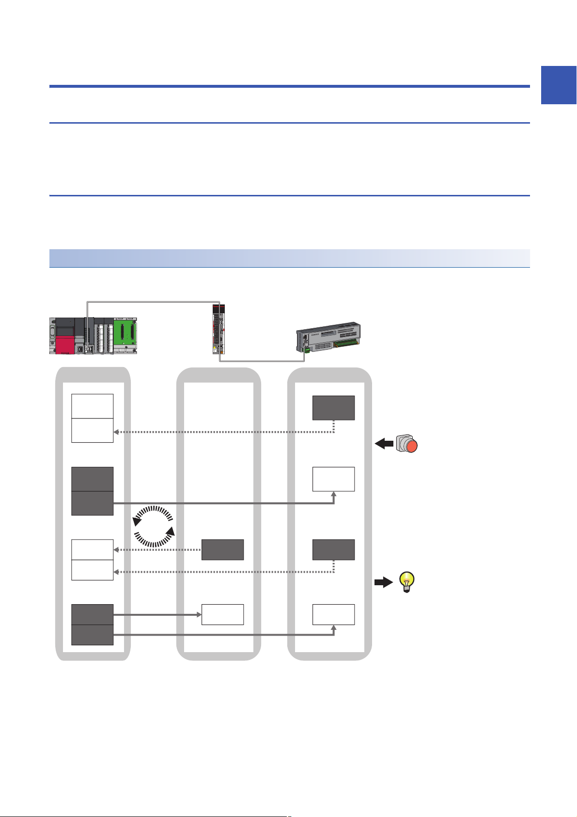
1.1 Cyclic Transmission
This allows data to be periodically exchanged among stations on the same network using slave labels.
• The slave labels can be assigned in "Network Configuration Settings" under "Basic Settings". ( Page 42 "CC-Link IE
TSN Configuration" Window)
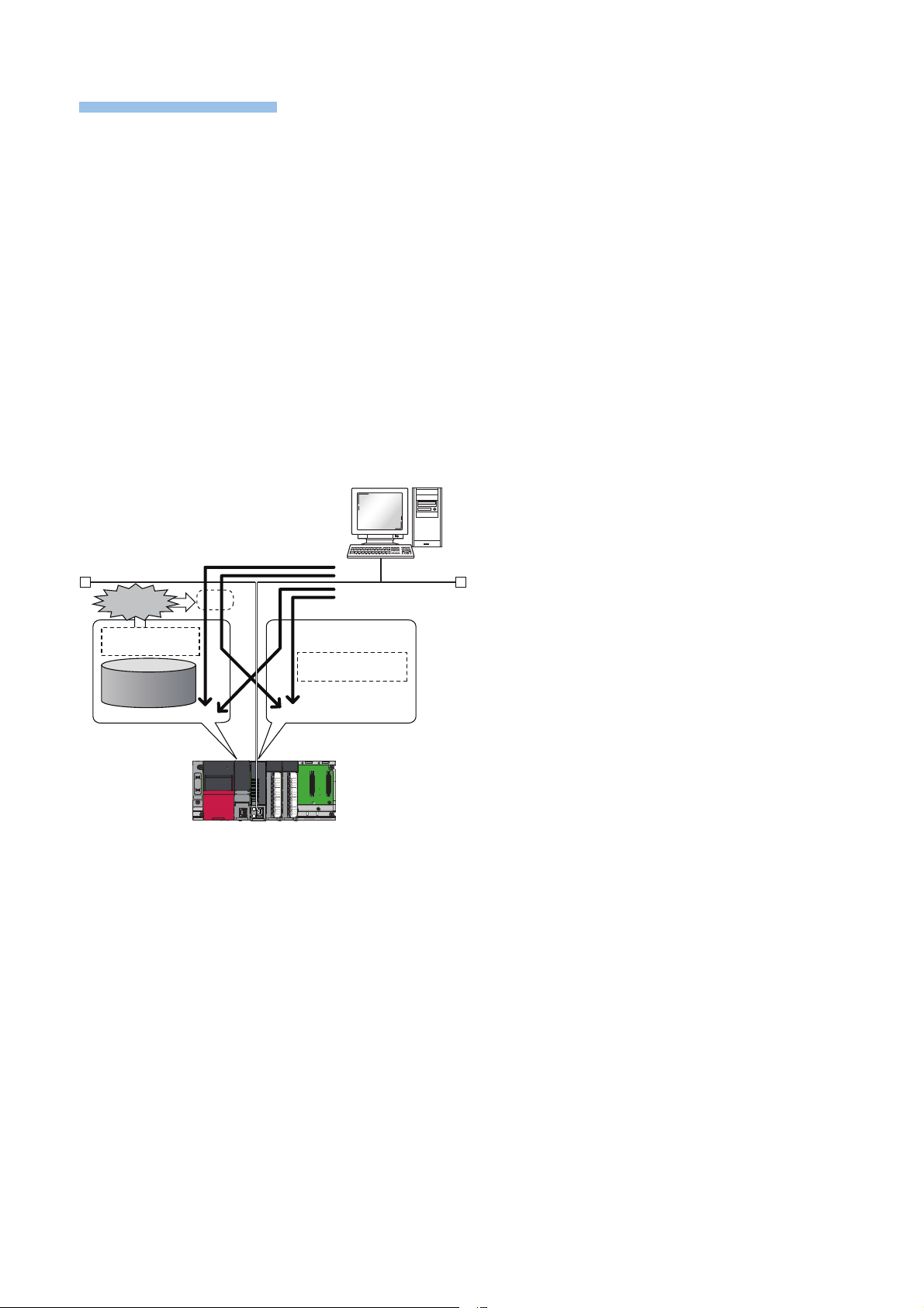
Communications using slave labels
This allows I/O data to be exchanged in units of bits and in units of words in the master station and slave station.
Slave labels can be used in the motion control station only.
This function is available for the motion ST program only.
Master station and remote stations
1:1 communications between the master station and each remote station. Remote stations do not communicate with each
other.
1
No.0, No.1, No.2 Station No.0 (master station), Station No.1, Station No.2
No.1, No.2 Send range: to station No.1, Send range: to station No.2
No.1, No.2 Send range: from station No.1, Send range: from station No.2
• Output from the master station
The status data of the slave labels of the master station is stored in the link devices (RY, RWw) of each remote station by cyclic data transfer processing.
The status data of the link devices (RY, RWw) of the remote station are output to the external device.
• Input from the remote station
The status data of the external device is stored in the link devices (RX, RWr) of the remote station.
The status data of the link devices (RX, RWr) of the remote station is stored in the slave labels of the master station by cyclic data transfer processing.
1 FUNCTIONS
1.1 Cyclic Transmission
17
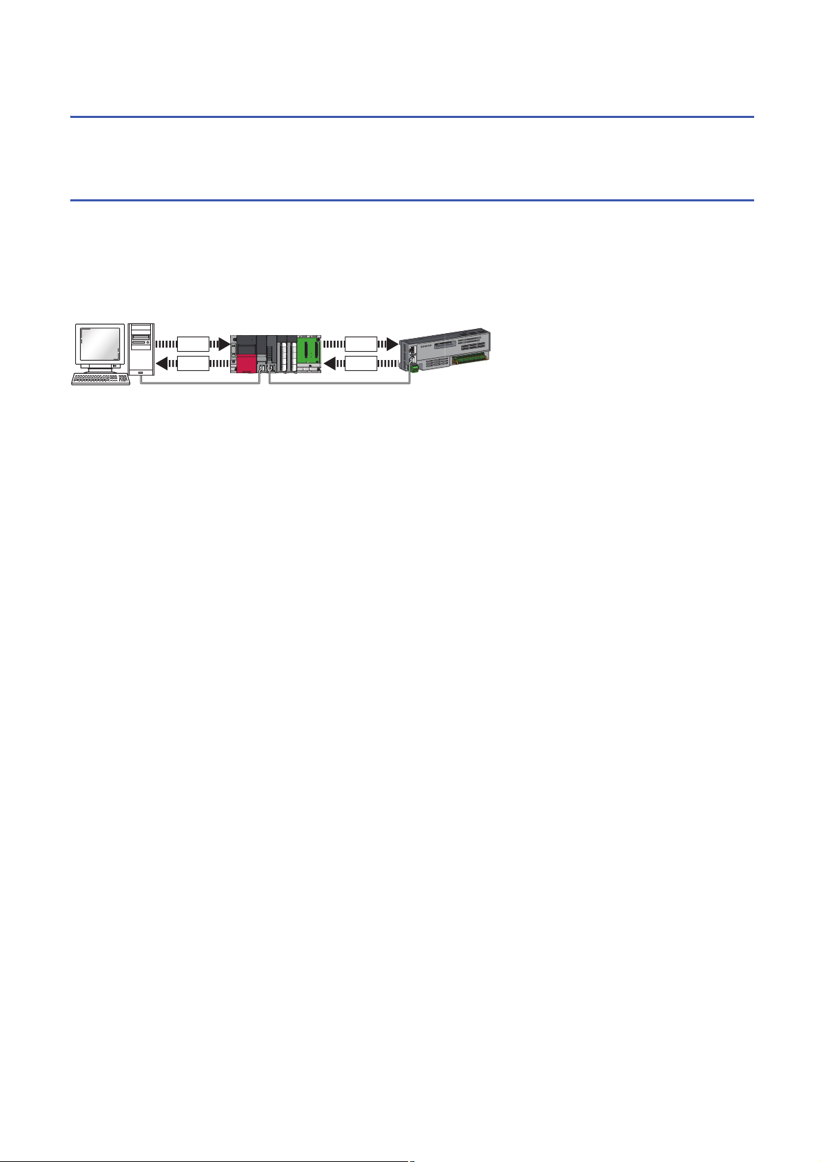
1.2 Transient Transmission
(1)
(6)
(4) (6)
(4)
(3)(2)
(5)
(3)
This uses communications at any timing.
Page 18 Communications using the SLMP
Communications using the SLMP
By SLMP, data is read/written from the external device (1) such as a personal computer or HMI (Human Machine Interface) to
I/O module devices of the master station (2) and (3) and the buffer memory of the remote station.
The Motion module can create, send (4), relay (5), and receive (6) SLMP messages. For details on SLMP, refer to the
following.
SLMP Reference Manual
18
1 FUNCTIONS
1.2 Transient Transmission
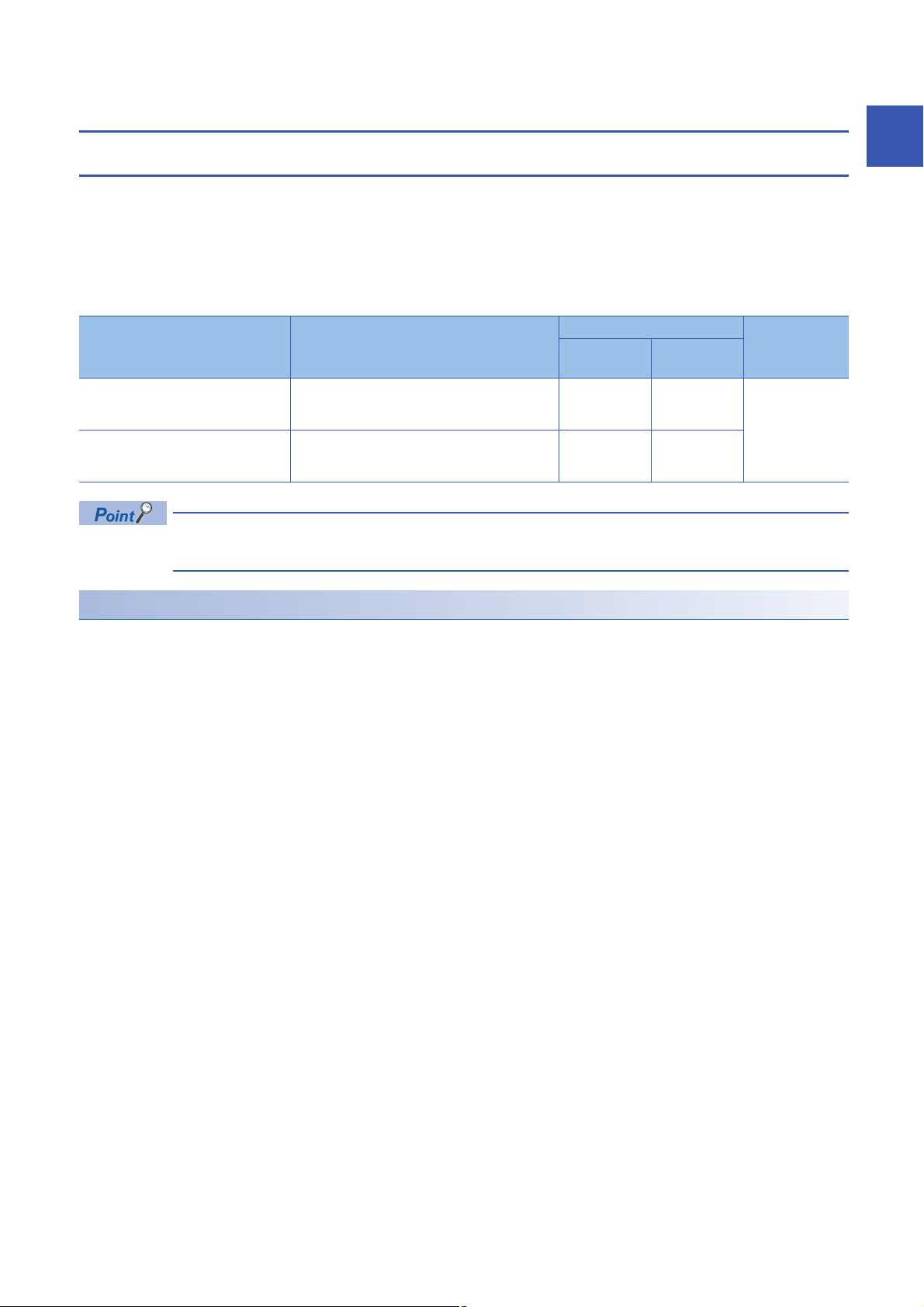
1.3 Ethernet Connection
Connection with MELSOFT products and a GOT
Programming and monitoring of the programmable controller with the engineering tool, and monitoring and testing of the
programmable controller from the GOT is performed via Ethernet. This function enables remote control using Ethernet's long-
distance connectivity and high-speed communications.
The section describes the methods of connecting the Motion module, MELSOFT product (such as engineering tool and MX
Component), and GOT.
: Connection available, : Connection not available
Connection method Purpose Availability Reference
Connection via hub
(Connection by specifying the IP
address)
Connection via hub
(Connection by specifying the network
No. and station No.)
For the procedures to connect the Motion module and GOT, refer to the following.
Manual for the GOT used
MELSOFT
product
To connect multiple MELSOFT products Page 19
To connect multiple MELSOFT products and GOTs
GOT
Connection via hub
1
Connection via hub
■Settings on the Motion module side
Sets the IP address of the Motion module using "Required Settings". ( Page 36 Station No./IP Address Settings)
When connecting by specifying the network No. and station No., set the network No. and station No. in "Required Settings".0
The Motion module can be connected to the MELSOFT product and GOT using the system dedicated connection, so no
settings are required in "Network Configuration Settings" under "Basic Settings".
1 FUNCTIONS
1.3 Ethernet Connection
19
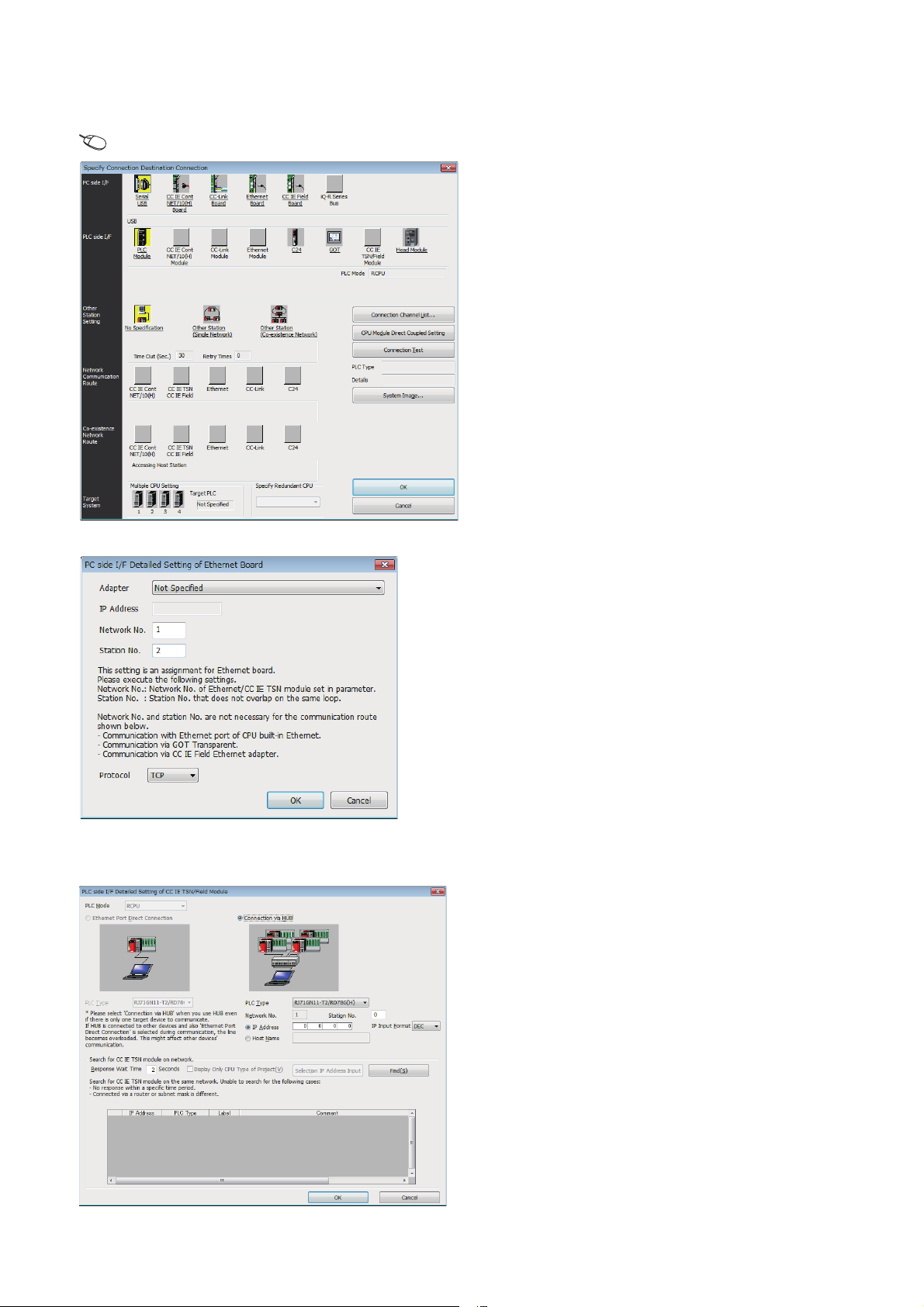
■Settings on the engineering tool side
Set in the "Specify Connection Destination Connection" window.
[Online] [Current Connection Destination]
1. Set "PC side I/F" to "Ethernet Board".
2. Double-click "Ethernet Board", and open the "PC side I/
F Detailed Setting of Ethernet Board" window.
3. Set the network No., station No., and protocol of the
personal computer.
TCP: A connection is established during communication.
Since data is exchanged while checking that the data has
correctly reached the communication destination, the data
reliability can be ensured. Note that the line load is larger
than UDP/IP communications.
UDP: Since a connection is not established during
communication and whether the communication destination
has correctly received the data is not checked, the line load is
lower. Note that the data reliability is lower than TCP/IP
communications.
4. Set the "PLC side I/F" to the module to be connected.
5. Double-click the icon set in step 4, and open the
detailed setting window.
6. Select "Connection via HUB" for the connection method,
and enter the station No. and IP address or host name
for the Motion module.
7. Specify "Other Station Setting" or "Network
Communication Route" if necessary.
20
1 FUNCTIONS
1.3 Ethernet Connection
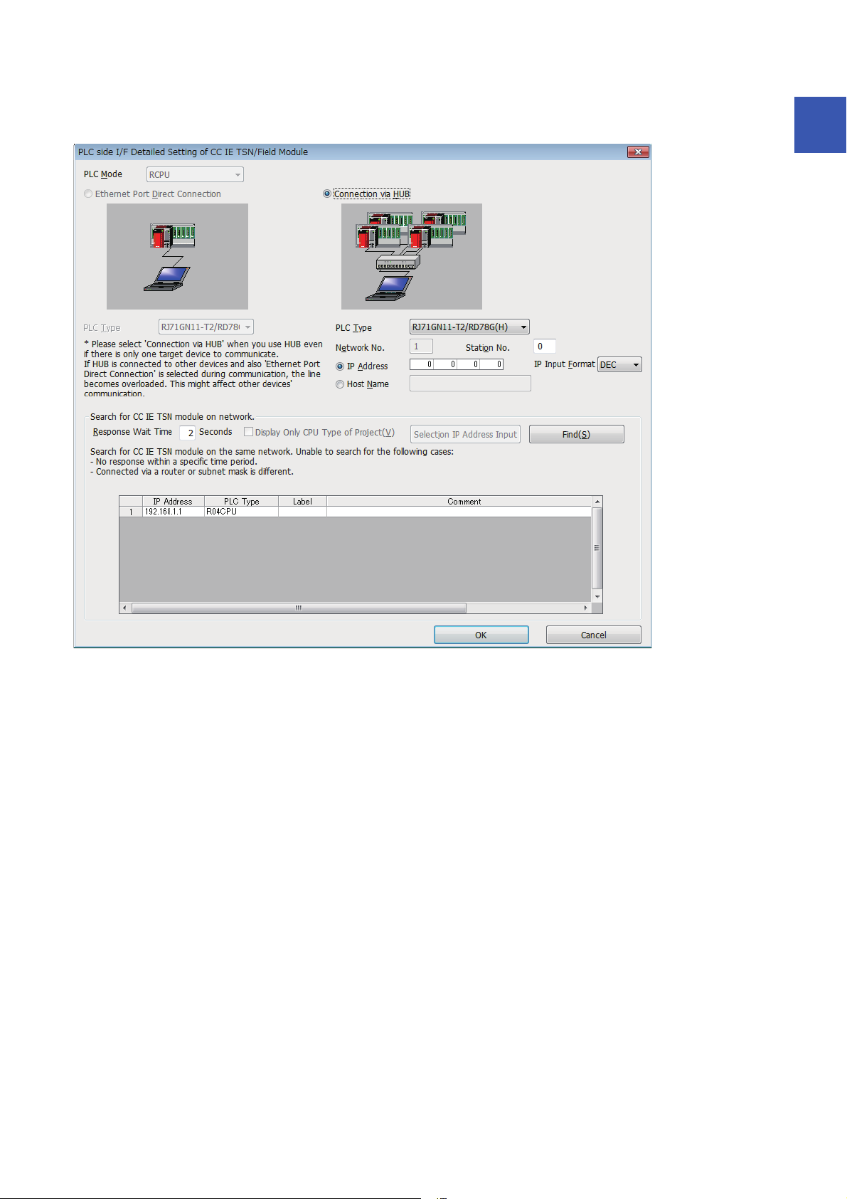
■Searching modules on the network
When connecting with a hub, a list of modules that can be searched for will appear by clicking the [Find] button on the detailed
setting window.
1
Search target modules are as follows.
• The control CPU of the Motion module connected to the same hub as the engineering tool
• The control CPU of the Motion module connected to cascade-connected hub
If the connected Motion module does not appear in the list after searching the modules on the network, check the following
items.
• Search cannot be performed if it is disabled with the IP filter.
• Modules connected via a router cannot be searched.
• If the module is connected via a wireless LAN, IP packet loss can prevent the Ethernet communication from stabilizing, and
may inhibit the module search.
• If there are modules with the same IP address in the list, review the IP address parameter settings for the Motion module.
• If the service processing load of the search-target CPU module is high, it may not be possible to search for the
corresponding module. If the search cannot be performed, increase the response waiting time in the search dialog, and
execute the search again.
1 FUNCTIONS
1.3 Ethernet Connection
21

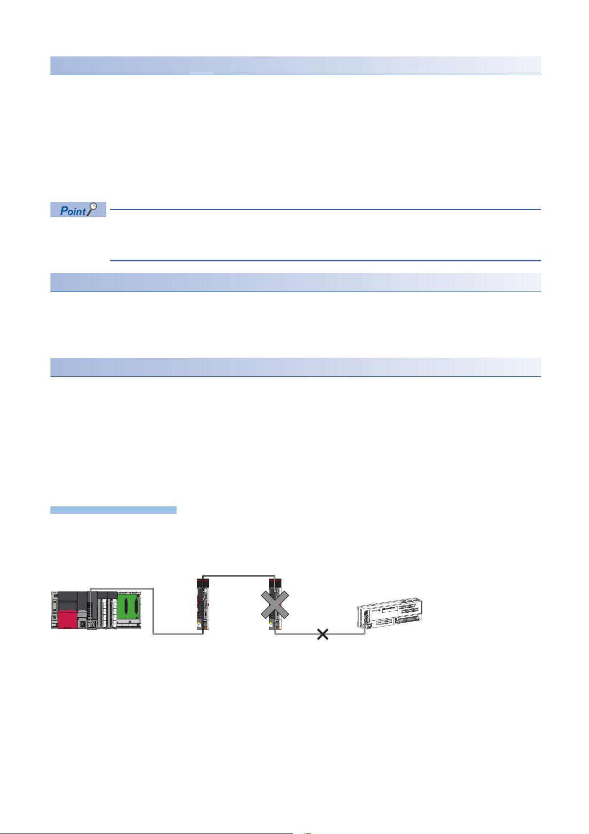
Connecting SLMP-compatible devices
Connect commercially available SLMP-compatible devices. A SLMP-compatible device can be introduced to the CC-Link IE
TSN system, resulting in easier linkage with an upper information network.
For details on SLMP, refer to the following.
SLMP Reference Manual
When the system structure is mixed with an Ethernet device, there are restrictions for the network topology
and connection order of the Ethernet device. (MELSEC iQ-R Motion Module User's Manual (Startup))
22
1 FUNCTIONS
1.3 Ethernet Connection

1.4 Security
No.0
HUB
(1) 192.168.1.1
(2) 192.168.1.5
Security for the network environment is structured by restricting access by each communication path that accesses the CPU
module. The following two access restriction methods can be used.
Page 23 IP filter
Page 25 Remote password
IP filter
Identifies the IP address of the access source, and prevents unauthorized access and data links.
By setting the IP address of the access source using the engineering tool, IP packets are allowed or blocked. (Allows or
blocks the IP packets received from the access source. IP packets sent from the own station are ignored.)
Use of this function is recommended when using in an environment connected to a LAN line.
1
When the "Allow" IP address is set to 192.168.1.1 using the IP filter of the master station No.0:
Only the Ethernet device (1) can access the master station, and the Ethernet device (2) cannot access the master station.
This function cannot be used when accessing via a network other than Ethernet or CC-Link IE TSN.
The IP filter is one method of preventing unauthorized access (such as program or data destruction) from an
external device. It does not completely prevent unauthorized access. Incorporate measures other than this
function if the programmable controller system's safety must be maintained against unauthorized access from
an external device. Mitsubishi shall not be held liable for any system problems that may occur from
unauthorized access.
Examples of measures for unauthorized access are given below.
• Install a firewall
1 FUNCTIONS
1.4 Security
23
Setting method
Precautions
No.0
No.1: 192.168.1.1 No.2: 192.168.1.2
No.3: 192.168.1.3
1. Set the IP address to be allowed or blocked in the "IP Filter Settings" window of "Security" under "Application Settings".
(Page 41 Security) A warning is displayed in the following cases.
• When blocking the IP address of the slave station set in "Network Configuration Settings" under "Basic Settings" was
attempted
• When the slave station is not set in "Network Configuration Settings" under "Basic Settings", and the "Allow" target IP
address is not set in the "IP Filter Settings" window (because the IP filter is fully blocked)
2. Write the module parameters to the CPU module.
3. The IP filter is enabled when the CPU module power is turned off and on or reset.
Even if the connection was specified in "Network Configuration Settings" under "Basic Settings" or by a
program, access from the external device is either allowed or blocked according to the setting in the "IP Filter
Settings" window.
Setting Target
Allow or block should be set to all IP addresses that connect to the same network. Also, set allow or block to the IP address of
the slave station that is registered in "Network Configuration Settings" under "Basic Settings".
Register the setting details to the master station, and allow or block the IP packets received from the slave station of the
registered IP address.
Operation
Even for the slave station registered in "Network Configuration Settings" under "Basic Settings", a station with an IP address
set as blocked can become a disconnected station. As a result, cyclic transmission and transient transmission are not
performed. Such a station is also displayed as a disconnected station on the "CC-Link IE TSN/CC-Link IE Field Diagnostics"
window. However, Ethernet devices are not displayed on the "CC-Link IE TSN/CC-Link IE Field Diagnostics" window. (
Page 54 CC-Link IE TSN/CC-Link IE Field Diagnostics)
When an IP packet is received from an IP address that is set as blocked, the denial is registered in the event history of the
master station.
( Page 84 Event List)
• Do not set the IP addresses of the master station or slave stations as blocked. When a slave station using line topology is
set as blocked, cyclic and transient transmissions cannot be performed on the slave stations that are connected after the
slave station set as blocked.
When the "Deny" IP address is set to 192.168.1.2 using the IP filter of the master station No.0:
Only the slave station No.1 can access the master station, and the slave station No.2 and slave station No.3 cannot access the master station.
• If there is a proxy server in the LAN line, block the IP address for the proxy server. If the IP address is allowed, it will not be
possible to prevent access from personal computers that access the proxy server.
• To block access from an external device to another station, block access to the connected station (station connected
directly to an external device) by using the IP filter.
24
1 FUNCTIONS
1.4 Security

Remote password
Permits or prohibits access from the external device to the CPU module via Motion module. This function can prevent
unauthorized access of the CPU module from a remote location.
The remote password is one method of preventing unauthorized access (such as program or data destruction)
from an external device. It does not completely prevent unauthorized access. Incorporate measures other
than this function if the programmable controller system's safety must be maintained against unauthorized
access from an external device. Mitsubishi shall not be held liable for any system problems that may occur
from unauthorized access.
Examples of measures for unauthorized access are given below.
• Install a firewall
Number of settable modules
Up to eight modules can be set for remote passwords.
When using the multiple CPU system configuration, up to eight modules can be set for each CPU module.
1
1 FUNCTIONS
1.4 Security
25
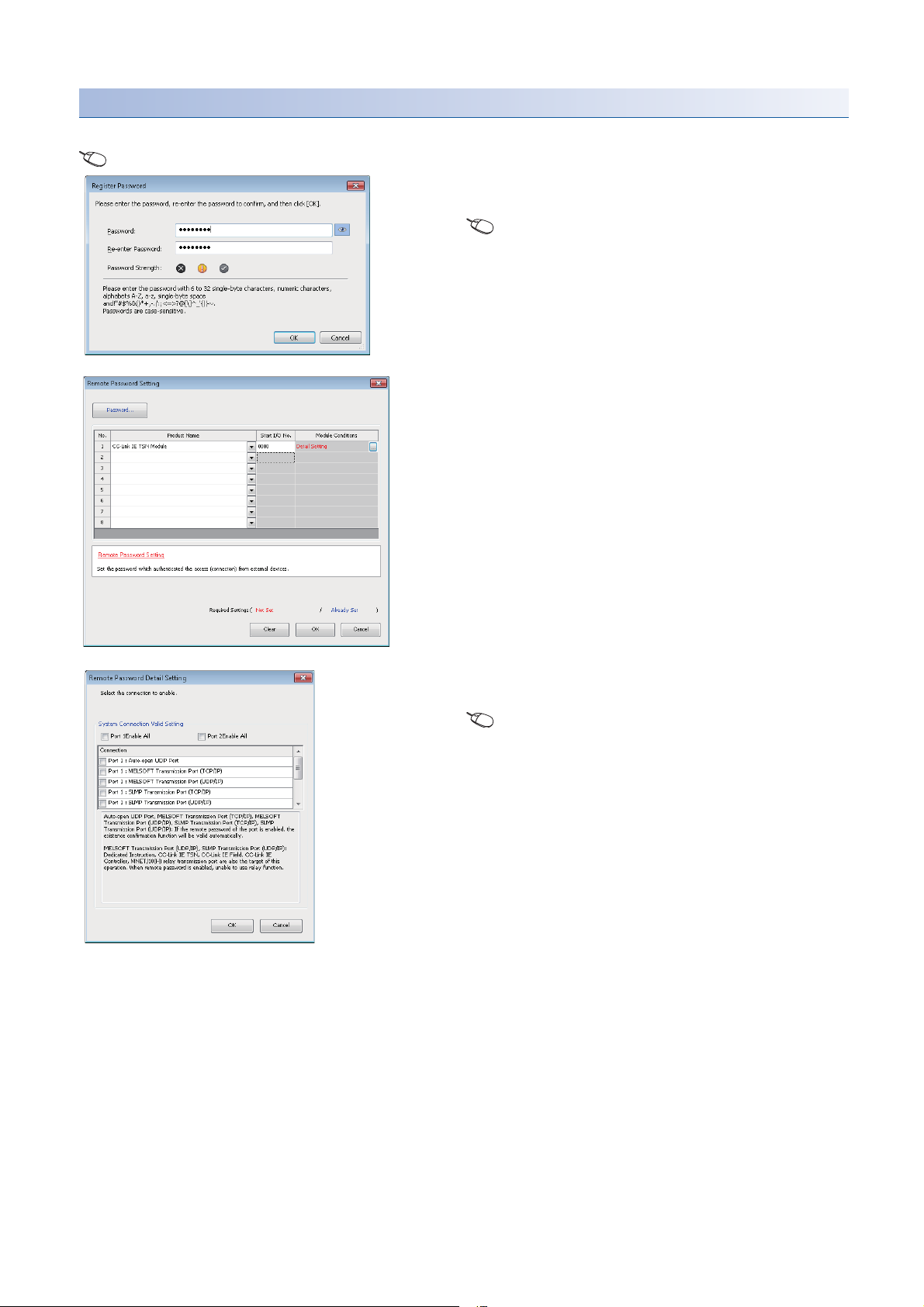
Setting method
Set on the "Remote Password Setting" window.
[Navigation window] [Parameter] [Remote Password]
1. Click the [Password] button, and register the remote
password on the "Register Password" window.
[Password] button
2. Select the module for which the remote password is to
be applied, and set the start I/O No..
3. Set the target connection on the "Remote Password
Detail Setting" window.
"Detail Setting" for the target module
4. Write the remote password to the CPU module.
5. The remote password is enabled when the CPU module
is reset or powered off and on.
■PING
This function uses the Ping command to perform an alive check of external devices whose access is permitted in UDP
communications. Therefore, if external devices do not respond to ping, an alive check error (event code 00906H) occurs.
When this function is used for UDP communications, check if the security setting of external devices (such as a firewall) is set
to respond to ping.
26
1 FUNCTIONS
1.4 Security

Access permitted/prohibited processing operation
This section describes the processing for permitting or prohibiting access of the CPU module with remote password by the
external device.
■Access permit processing (Unlock processing)
The external device trying to communicate unlocks the remote password set for the connected Motion module.
If the password is not unlocked, the Motion module to which the external device is connected prohibits access, so an error
occurs in the external device.
The unlocking methods are shown below.
• SLMP dedicated command (Remote Password Unlock)
• Input password from engineering tool
■Access processing
Access to the specified station is possible when the remote password is correctly unlocked. Execute the arbitrary access.
■Access prohibit processing (Lock processing)
When access to the specified station ends, lock the remote password from the external device to disable subsequent access.
The locking methods are shown below.
• SLMP dedicated command (Remote Password Lock)
• Lock with engineering tool (executed automatically)
1
1 FUNCTIONS
1.4 Security
27
Precautions
The following section lists the precautions for using remote password.
Ethernet
A
B
C
D
Enable/
Disable
Remote password
check
No remote password
parameter
Remote password
parameter
■Set connection
Set the remote password for the connection used for data communication with an external device that can execute the unlock/
lock processing.
■When remote password is set for UDP/IP connection
• Determine the external device to communicate with and perform data communication. (With UDP/IP, after the remote
password is unlocked, data can be exchanged with devices other than the unlocked external device too. Determine the
communication destination before starting use.)
• Always lock the remote password after data communication is finished. (If the remote password is not locked, the unlocked
state is held until timeout occurs.)
■TCP/IP close processing
If the TCP/IP is closed before the TCP/IP is locked, the CPU module will automatically start the lock processing.
■Remote password valid range
The remote password is valid only for access from the Motion module for which the parameters are set. When using multiple
CPU modules in a multiple CPU system, set a remote password for each CPU module for requiring a remote password.
The remote password is checked when accessing with path A or B.
The remote password is not checked when accessing with path C or D.
28
1 FUNCTIONS
1.4 Security
 Loading...