

Page 1
MITSUBISHI ELECTRIC SERVO SYSTEM CONTROLLER
Migration Guide from Positioning Module to
Simple Motion Module [QD74MH ය RD77MS]
Page 2

Page 3
● SAFETY PRECAUTIONS ●
(Read these precautions before using this product.)
Before using this product, please read this manual and the relevant manuals carefully and pay full
attention to safety to handle the product correctly.
The precautions given in this manual are concerned with this product only. Refer to the MELSEC iQ-R
Module Configuration Manual for a description of the PLC system safety precautions.
In this manual, the safety precautions are classified into two levels: “ WARNING” and “ CAUTION”.
Under some circumstances, failure to observe the precautions given under “ CAUTION” may lead to
serious consequences.
Observe the precautions of both levels because they are important for personal and system safety.
Make sure that the end users read this manual and then keep the manual in a safe place for future
reference.
WARNING
CAUTION
Indicates that incorrect handling may cause hazardous conditions,
resulting in death or severe injury.
Indicates that incorrect handling may cause hazardous conditions,
resulting in minor or moderate injury or property damage.
A - 1
Page 4

[Design Precautions]
WARNING
● Configure safety circuits external to the programmable controller to ensure that the entire system
operates safely even when a fault occurs in the external power supply or the programmable
controller.
Failure to do so may result in an accident due to an incorrect output or malfunction.
(1) Emergency stop circuits, protection circuits, and protective interlock circuits for conflicting
operations (such as forward/reverse rotations or upper/lower limit positioning) must be
configured external to the programmable controller.
(2) When the programmable controller detects an abnormal condition, it stops the operation and
all outputs are:
• Turned off if the overcurrent or overvoltage protection of the power supply module is
activated.
• Held or turned off according to the parameter setting if the self-diagnostic function of the CPU
module detects an error such as a watchdog timer error.
(3) All outputs may be turned on if an error occurs in a part, such as an I/O control part, where the
CPU module cannot detect any error. To ensure safety operation in such a case, provide a
safety mechanism or a fail-safe circuit external to the programmable controller. For a fail-safe
circuit example, refer to "General Safety Requirements" in the MELSEC iQ-R Module
Configuration Manual.
(4) Outputs may remain on or off due to a failure of a component such as a relay and transistor in
an output circuit. Configure an external circuit for monitoring output signals that could cause a
serious accident.
● In an output circuit, when a load current exceeding the rated current or an overcurrent caused by
a load short-circuit flows for a long time, it may cause smoke and fire. To prevent this, configure
an external safety circuit, such as a fuse.
● Configure a circuit so that the programmable controller is turned on first and then the external
power supply. If the external power supply is turned on first, an accident may occur due to an
incorrect output or malfunction.
● For the operating status of each station after a communication failure, refer to manuals relevant to
the network. Incorrect output or malfunction due to a communication failure may result in an
accident.
● When connecting an external device with a CPU module or intelligent function module to modify
data of a running programmable controller, configure an interlock circuit in the program to ensure
that the entire system will always operate safely. For other forms of control (such as program
modification, parameter change, forced output, or operating status change) of a running
programmable controller, read the relevant manuals carefully and ensure that the operation is
safe before proceeding. Improper operation may damage machines or cause accidents.
● Especially, when a remote programmable controller is controlled by an external device,
immediate action cannot be taken if a problem occurs in the programmable controller due to a
communication failure. To prevent this, configure an interlock circuit in the program, and
determine corrective actions to be taken between the external device and CPU module in case
of a communication failure.
A - 2
Page 5

[Design Precautions]
WARNING
● Do not write any data to the "system area" and "write-protect area" of the buffer memory in the
module. Also, do not use any "use prohibited" signals as an output signal from the CPU module
to each module. Doing so may cause malfunction of the programmable controller system. For
the "system area", "write-protect area", and the "use prohibited" signals, refer to the user's
manual for the
module used.
● If a communication cable is disconnected, the network may be unstable, resulting in a
communication failure of multiple stations. Configure an interlock circuit in the program to
ensure that the entire system will always operate safely even if communications fail. Failure to
do so may result in an accident due to an incorrect output or malfunction.
● To maintain the safety of the programmable controller system against unauthorized access from
external devices via the network, take appropriate measures. To maintain the safety against
unauthorized access via the Internet, take measures such as installing a firewall.
● Configure safety circuits external to the programmable controller to ensure that the entire
system operates safely even when a fault occurs in the external power supply or the
programmable controller. Failure to do so may result in an accident due to an incorrect output or
malfunction.
(1) Machine home position return is controlled by two kinds of data: a home position return
direction and a home position return speed. Deceleration starts when the proximity dog
signal turns on. If an incorrect home position return direction is set, motion control may
continue without deceleration. To prevent machine damage caused by this, configure an
interlock circuit external to the programmable controller.
(2) When the module detects an error, the motion slows down and stops or the motion rapidly
stops, depending on the stop group setting in parameter. Set the parameter to meet the
specifications of a positioning control system. In addition, set the home position return
parameter and positioning data within the specified setting range.
(3) Outputs may remain on or off, or become undefined due to a failure of a component such as
an insulation element and transistor in an output circuit, where the module cannot detect any
error. In a system that the incorrect output could cause a serious accident, configure an
external circuit for monitoring output signals.
● If safety standards (ex., robot safety rules, etc.,) apply to the system using the module, servo
amplifier and servomotor, make sure that the safety standards are satisfied.
● Construct a safety circuit externally of the module or servo amplifier if the abnormal operation of
the module or servo amplifier differs from the safety directive operation in the system.
● Do not remove the SSCNETIII cable while turning on the control circuit power supply of the
module and servo amplifier. Do not see directly the light generated from SSCNETIII connector
of the module or servo amplifier and the end of SSCNETIII cable. When the light gets into eyes,
you may feel something wrong with eyes. (The light source of SSCNETIII complies with class1
defined in JISC6802 or IEC60825-1.)
A - 3
Page 6

[Design Precautions]
WARNING
● Do not install the control lines or communication cables together with the main circuit lines or
power cables. Keep a distance of 100 mm or more between them. Failure to do so may result in
malfunction due to noise.
● During control of an inductive load such as a lamp, heater, or solenoid valve, a large current
(approximately ten times greater than normal) may flow when the output is turned from off to on.
Therefore, use a module that has a sufficient current rating.
● After the CPU module is powered on or is reset, the time taken to enter the RUN status varies
depending on the system configuration, parameter settings, and/or program size. Design
circuits so that the entire system will always operate safely, regardless of the time.
● Do not power off the programmable controller or reset the CPU module while the settings are
being written. Doing so will make the data in the flash ROM and SD memory card undefined.
The values need to be set in the buffer memory and written to the flash ROM and SD memory
card again. Doing so also may cause malfunction or failure of the module.
● When changing the operating status of the CPU module from external devices (such as the
remote RUN/STOP functions), select "Do Not Open in Program" for "Opening Method Setting"
in the module parameters. If "Open in Program" is selected, an execution of the remote STOP
function causes the communication line to close. Consequently, the CPU module cannot reopen
the communication line, and external devices cannot execute the remote RUN functions.
A - 4
Page 7
[Installation Precautions]
WARNING
● Shut off the external power supply (all phases) used in the system before mounting or removing
the module. Failure to do so may result in electric shock or cause the module to fail or
malfunction.
[Installation Precautions]
CAUTION
● Use the programmable controller in an environment that meets the general specifications in the
Safety Guidelines included with the base unit. Failure to do so may result in electric shock, fire,
malfunction, or damage to or deterioration of the product.
● To mount a module, place the concave part(s) located at the bottom onto the guide(s) of the
base unit, and push in the module until the hook(s) located at the top snaps into place. Incorrect
interconnection may cause malfunction, failure, or drop of the module.
● To mount a module with no module fixing hook, place the concave part(s) located at the bottom
onto the guide(s) of the base unit, push in the module, and fix it with screw(s). Incorrect
interconnection may cause malfunction, failure, or drop of the module.
● When using the programmable controller in an environment of frequent vibrations, fix the
module with a screw.
● Tighten the screws within the specified torque range. Undertightening can cause drop of the
screw, short circuit, or malfunction. Overtightening can damage the screw and/or module,
resulting in drop, short circuit, or malfunction.
● When using an extension cable, connect it to the extension cable connector of the base unit
securely. Check the connection for looseness. Poor contact may cause malfunction.
● When using an SD memory card, fully insert it into the SD memory card slot. Check that it is
inserted completely. Poor contact may cause malfunction.
● Securely insert an extended SRAM cassette into the cassette connector of the CPU module.
After insertion, close the cassette cover and check that the cassette is inserted completely. Poor
contact may cause malfunction.
● Do not directly touch any conductive parts and electronic components of the module, SD
memory card, extended SRAM cassette, or connector. Doing so can cause malfunction or
failure of the module.
[Wiring Precautions]
WARNING
● Shut off the external power supply (all phases) used in the system before installation and wiring.
Failure to do so may result in electric shock or cause the module to fail or malfunction.
● After installation and wiring, attach the included terminal cover to the module before turning it on
for operation. Failure to do so may result in electric shock.
A - 5
Page 8

[Wiring Precautions]
● Individually ground the FG and LG terminals of the programmable controller with a ground
resistance of 100 ohms or less. Failure to do so may result in electric shock or malfunction.
● Use applicable solderless terminals and tighten them within the specified torque range. If any
spade solderless terminal is used, it may be disconnected when the terminal screw comes
loose, resulting in failure.
● Check the rated voltage and signal layout before wiring to the module, and connect the cables
correctly. Connecting a power supply with a different voltage rating or incorrect wiring may
cause fire or failure.
● Connectors for external devices must be crimped or pressed with the tool specified by the
manufacturer, or must be correctly soldered. Incomplete connections may cause short circuit,
fire, or malfunction.
● Securely connect the connector to the module. Poor contact may cause malfunction.
● Do not install the control lines or communication cables together with the main circuit lines or
power cables. Keep a distance of 100 mm or more between them. Failure to do so may result in
malfunction due to noise.
● Place the cables in a duct or clamp them. If not, dangling cable may swing or inadvertently be
pulled, resulting in damage to the module or cables or malfunction due to poor contact. Do not
clamp the extension cables with the jacket stripped. Doing so may change the characteristics of
the cables, resulting in malfunction.
● Check the interface type and correctly connect the cable. Incorrect wiring (connecting the cable
to an incorrect interface) may cause failure of the module and external device.
● Tighten the terminal screws or connector screws within the specified torque range.
Undertightening can cause drop of the screw, short circuit, fire, or malfunction. Overtightening
can damage the screw and/or module, resulting in drop, short circuit, fire, or malfunction.
● When disconnecting the cable from the module, do not pull the cable by the cable part. For the
cable with connector, hold the connector part of the cable. For the cable connected to the
terminal block, loosen the terminal screw. Pulling the cable connected to the module may result
in malfunction or damage to the module or cable.
● Prevent foreign matter such as dust or wire chips from entering the module. Such foreign matter
can cause a fire, failure, or malfunction.
● A protective film is attached to the top of the module to prevent foreign matter, such as wire
chips, from entering the module during wiring. Do not remove the film during wiring. Remove it
for heat dissipation before system operation.
● Programmable controllers must be installed in control panels. Connect the main power supply
to the power supply module in the control panel through a relay terminal block. Wiring and
replacement of a power supply module must be performed by qualified maintenance personnel
with knowledge of protection against electric shock. For wiring, refer to the MELSEC iQ-R
Module Configuration Manual.
● For Ethernet cables to be used in the system, select the ones that meet the specifications in the
user's manual for the module used. If not, normal data transmission is not guaranteed.
A - 6
Page 9
[Startup and Maintenance Precautions]
WARNING
● Do not touch any terminal while power is on. Doing so will cause electric shock or malfunction.
● Correctly connect the battery connector. Do not charge, disassemble, heat, short-circuit, solder,
or throw the battery into the fire. Also, do not expose it to liquid or strong shock. Doing so will
cause the battery to produce heat, explode, ignite, or leak, resulting in injury and fire.
● Shut off the external power supply (all phases) used in the system before cleaning the module
or retightening the terminal screws, connector screws, or module fixing screws. Failure to do so
may result in electric shock.
[Startup and Maintenance Precautions]
CAUTION
● When connecting an external device with a CPU module or intelligent function module to modify
data of a running programmable controller, configure an interlock circuit in the program to
ensure that theentire system will always operate safely. For other forms of control (such as
program modification, parameter change, forced output, or operating status change) of a
running programmable controller, read the relevant manuals carefully and ensure that the
operation is safe before proceeding. Improper operation may damage machines or cause
accidents.
● Especially, when a remote programmable controller is controlled by an external device,
immediate action cannot be taken if a problem occurs in the programmable controller due to a
communication failure. To prevent this, configure an interlock circuit in the program, and
determine corrective actions to be taken between the external device and CPU module in case
of a communication failure.
● Do not disassemble or modify the modules. Doing so may cause failure, malfunction, injury, or a
fire.
● Use any radio communication device such as a cellular phone or PHS (Personal Handy-phone
System) more than 25 cm away in all directions from the programmable controller. Failure to do
so may cause malfunction.
A - 7
Page 10

[Startup and Maintenance Precautions]
CAUTION
● Shut off the external power supply (all phases) used in the system before mounting or removing
the module. Failure to do so may cause the module to fail or malfunction.
● Tighten the screws within the specified torque range. Undertightening can cause drop of the
component or wire, short circuit, or malfunction. Overtightening can damage the screw and/or
module, resulting in drop, short circuit, or malfunction.
● After the first use of the product, do not mount/remove the module to/from the base unit, and
the terminal block to/from the module, and do not insert/remove the extended SRAM cassette
to/from the CPU module more than 50 times (IEC 61131-2 compliant) respectively. Exceeding
the limit may cause malfunction.
● After the first use of the product, do not insert/remove the SD memory card to/from the CPU
module more than 500 times. Exceeding the limit may cause malfunction.
● Do not touch the metal terminals on the back side of the SD memory card. Doing so may cause
malfunction or failure of the module.
● Do not touch the integrated circuits on the circuit board of an extended SRAM cassette. Doing
so may cause malfunction or failure of the module.
● Do not drop or apply shock to the battery to be installed in the module. Doing so may damage
the battery, causing the battery fluid to leak inside the battery. If the battery is dropped or any
shock is applied to it, dispose of it without using.
● Startup and maintenance of a control panel must be performed by qualified maintenance
personnel with knowledge of protection against electric shock. Lock the control panel so that
only qualified maintenance personnel can operate it.
● Before handling the module, touch a conducting object such as a grounded metal to discharge
the static electricity from the human body. Failure to do so may cause the module to fail or
malfunction.
● Before testing the operation, set a low speed value for the speed limit parameter so that the
operation can be stopped immediately upon occurrence of a hazardous condition.
● Confirm and adjust the program and each parameter before operation. Unpredictable
movements may occur depending on the machine.
● When using the absolute position system function, on starting up, and when the module or
absolute position motor has been replaced, always perform a home position return.
● Before starting the operation, confirm the brake function.
● Do not perform a megger test (insulation resistance measurement) during inspection.
● After maintenance and inspections are completed, confirm that the position detection of the
absolute position detection function is correct.
● Lock the control panel and prevent access to those who are not certified to handle or install
electric equipment.
A - 8
Page 11
[Operating Precautions]
CAUTION
● When changing data and operating status, and modifying program of the running programmable
controller from an external device such as a personal computer connected to an intelligent
function module, read relevant manuals carefully and ensure the safety before operation.
Incorrect change or modification may cause system malfunction, damage to the machines, or
accidents.
● Do not power off the programmable controller or reset the CPU module while the setting values
in the buffer memory are being written to the flash ROM in the module. Doing so will make the
data in the flash ROM and SD memory card undefined. The values need to be set in the buffer
memory and written to the flash ROM and SD memory card again. Doing so also may cause
malfunction or failure of the module.
● Note that when the reference axis speed is specified for interpolation operation, the speed of
the partner axis (2nd, 3rd, or 4th axis) may exceed the speed limit value.
● Do not go near the machine during test operations or during operations such as teaching. Doing
so may lead to injuries.
[Disposal Precautions]
CAUTION
● When disposing of this product, treat it as industrial waste.
● When disposing of batteries, separate them from other wastes according to the local
regulations. For details on battery regulations in EU member states, refer to the MELSEC iQ-R
Module Configuration
Manual.
[Transportation Precautions]
CAUTION
● When transporting lithium batteries, follow the transportation regulations. For details on the
regulated models, refer to the MELSEC iQ-R Module Configuration Manual.
● The halogens (such as fluorine, chlorine, bromine, and iodine), which are contained in a
fumigant used for disinfection and pest control of wood packaging materials, may cause failure
of the product. Prevent the entry of fumigant residues into the product or consider other
methods (such as heat treatment) instead of fumigation. The disinfection and pest control
measures must be applied to unprocessed raw wood.
A - 9
Page 12
REVISIONS
Print Date Manual No. Revision
Sep., 2018 L(NA)03170ENG-A First edition
This manual confers no industrial property rights or any rights of any other kind, nor does it confer any patent
licenses. Mitsubishi Electric Corporation cannot be held responsible for any problems involving industrial property
rights which may occur as a result of using the contents noted in this manual.
2018 MITSUBISHI ELECTRIC CORPORATION
A - 10
Page 13

INTRODUCTION
Please read this manual carefully so that equipment is used to its optimum.
CONTENTS
Safety Precautions ......................................................................................................................................... A- 1
Revisions ···························································································································· A-10
Contents ····························································································································· A-11
1. OVERVIEW OF MIGRATION FROM QD74MH TO RD77MS 1- 1 to 1-14
1.1 Benefits of Migration ········································································································ 1- 1
1.2 Main Target Models for Migration ······················································································· 1- 2
1.3 System Configuration ······································································································ 1- 4
1.3.1 System configuration using QD74MH before migration ····················································· 1- 4
1.3.2 System configuration using RD77MS after migration ························································ 1- 4
1.4 Case Study on Migration ·································································································· 1- 5
1.4.1 Whole system migration (recommended) ······································································· 1- 6
1.4.2 Phased migration ······································································································ 1- 7
1.4.3 Separate repair ········································································································· 1- 8
1.5 Project Diversion ············································································································ 1-10
1.6 Relevant Documents ······································································································· 1-11
1.6.1 Relevant catalogs ····································································································· 1-11
1.6.2 Relevant manuals ····································································································· 1-12
2. DETAILS OF MIGRATION FROM QD74MH TO RD77MS 2- 1 to 2- 32
2.1 Table of Components and Software ··················································································· 2- 1
2.1.1 Servo amplifiers and servo motors ················································································ 2- 2
2.1.2 Engineering environment (required) ·············································································· 2- 3
2.2 Differences Between QD74MH and RD77MS ······································································· 2- 4
2.3 Forced Stop Input Cable ·································································································· 2-17
2.4 Project Diversion ············································································································ 2-20
2.4.1 Project diversion procedures by engineering environment ················································· 2-20
2.4.2 List of divertible/not divertible data ················································································· 2-24
A - 11
Page 14

MEMO
A - 12
Page 15

1. OVERVIEW OF MIGRATION FROM QD74MH TO RD77MS
1. OVERVIEW OF MIGRATION FROM QD74MH TO RD77MS
1
1.1 Benefits of Migration
Migrating from the existing system using QD74MH Positioning modules to a new system using
MELSEC iQ-R series Simple Motion module RD77MS16/RD77MS8 (hereinafter called RD77MS)
is recommended. We also recommend migrating servo amplifiers to the MR-J4 series at the
same time.
Migrating not only allows the system to run for longer periods, but also has the following
advantages.
(1) High functionality of Positioning module (Simple Motion module)
The Simple Motion module achieves further advanced motion control with a wide variety of
motion control functions such as synchronous control, in addition to positioning control.
The replaced model offers various new auxiliary features including cam detection function
and cam auto generation function, helping to reduce programming time further.
Increased productivity from higher functionality of the controller
→
(2) High-speed communication by SSCNETIII/H
Speeding up and improving noise tolerance of servo system network communications are
achieved by optical communication. A long distance cable of 100 m can be also used.
Increased speeds over the entire facility
→
(3) Servo amplifier MR-J4 and servo motor
The MR-J4 series achieves high performance operation with a variety of functions including
one-touch tuning, a 22-bit high resolution encoder (4194304 pulse/rev), and 2.5 kHz speed
frequency response. The product lineup includes multi-axis servo amplifiers that contribute to
energy saving, space saving, and reduced wiring of a machine. The MR-J4 series compatible
rotary servo motor, HG series enables to output high torque at high speed. Linear servo
motors and direct drive motors are also available. Select the motor type according to your
application from our extensive product lineup.
Increase of applications, improved performance, energy saving, downsizing, and reduced
→
wiring of drive systems
(4) Reliable monitoring functions
With our engineering software, the system status is easily monitored just by selecting
monitoring items that your system needs from its wealth of monitoring information.
In addition, operation is checked through waveforms and each device data collected by
digital oscilloscope and GX Logviewer
→ A strong support for troubleshooting
(5) Lower maintenance cost
After 5 years of usage, the products will need maintenance, such as replacement of the whole
circuit board due to the life of components including electrolytic capacitors and memories.
To use the system the longest possible, an early migration to the latest model is
recommended in terms of performance and quality.
Increased equipment longevity
→
1 - 1
Page 16
1. OVERVIEW OF MIGRATION FROM QD74MH TO RD77MS
1.2 Main Target Models for Migration
The main target models for replacement described in this section are as follows.
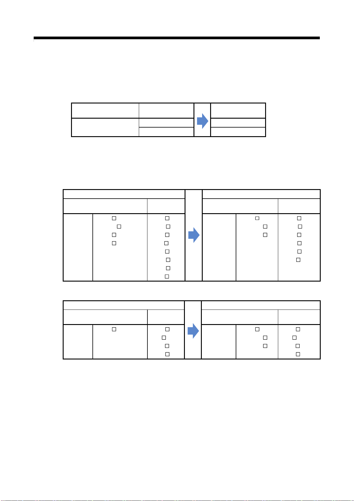
(1) Positioning modules
Product name
SSCNETIII compatible
Positioning module
QD74MH8 RD77MS8
QD74MH16 RD77MS16
Model
before migration
after migration
(2) Servo amplifiers and servo motors
The existing MR-J3 series servo amplifiers can be used in the migrated system with RD77MS,
however, it is strongly recommended to replace them with the MR-J4 series.
(a) Servo amplifiers and rotary servo motors
Before migration from QD74MH
MR-J3
series
Servo amplifier
MR-J3- B
MR-J3W-
MR-J3-
MR-J3- B-RJ006
BS
B
Rotary
servo motor
HF-KP
HF-MP
HF-SP
HF-JP
HC-LP
HC-RP
HC-UP
HA-LP
MR-J4
series
Servo amplifier
(b) Servo amplifiers and linear servo motors
Before migration from QD74MH
Linear
servo motor
LM-F
LM-K2
LM-U2
MR-J4
series
Servo amplifier
MR-J3
series
Servo amplifier
MR-J3- B-RJ004 LM-H2
Model
After migration to RD77MS
servo motor
MR-J4-
MR-J4W2-
MR-J4W3-
After migration to RD77MS
MR-J4-
MR-J4W2- B
MR-J4W3-
B(-RJ)
B(-RJ)
B
B
B
HG-KR
HG-MR
HG-SR
HG-RR
HG-UR
HG-JR
servo motor
LM-H3
LM-F
LM-K2
LM-U2
Rotary
Linear
1 - 2
Page 17
1. OVERVIEW OF MIGRATION FROM QD74MH TO RD77MS
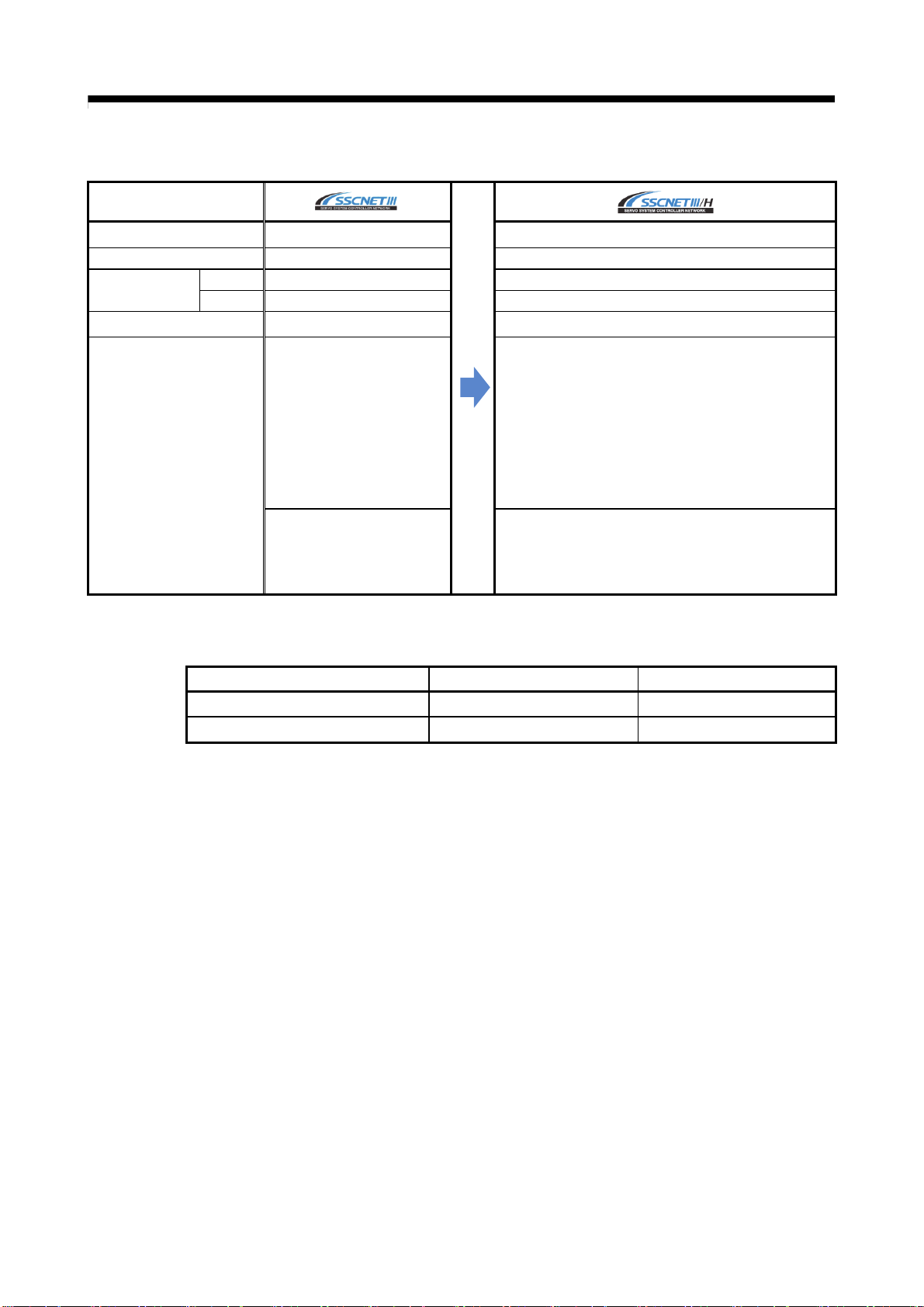
Communications medium Optical fiber cable
Communications speed 50 Mbps 150 Mbps
Communications
cycle
Number of control axes
Transmission distance
(3) Servo system network
Item
Send 0.44 ms/0.88 ms 0.222 ms/0.444 ms/0.888 ms
Receive 0.44 ms/0.88 ms 0.222 ms/0.444 ms/0.888 ms
Up to 16 axes/line
[Standard code for inside panel]
Up to 3 m between stations
Maximum overall distance:
48 m (3 m × 16 axes)
[Standard cable for outside panel]
Up to 20 m between stations
Maximum overall distance:
320 m (20 m × 16 axes)
[Long distance cable]
Up to 50 m between stations
Maximum overall distance:
800 m (50 m × 16 axes)
(same as SSCNETIII)
←
(same as SSCNETIII)
←
[Standard code for inside panel and standard cable for
outside panel]
Up to 20 m between stations
Maximum overall distance: 320 m (20 m × 16 axes)
[Long distance cable]
Up to 100 m between stations
Maximum overall distance: 1600 m (100 m × 16 axes)
(4) Engineering environment (required)
Product name Model Version
MELSOFT GX Works3
MELSOFT MR Configurator2
SW1DND-GXW3-E Ver.1.046Y or later
SW1DNC-MRC2-E Ver.1.27D or later
1 - 3
Page 18
p
1. OVERVIEW OF MIGRATION FROM QD74MH TO RD77MS
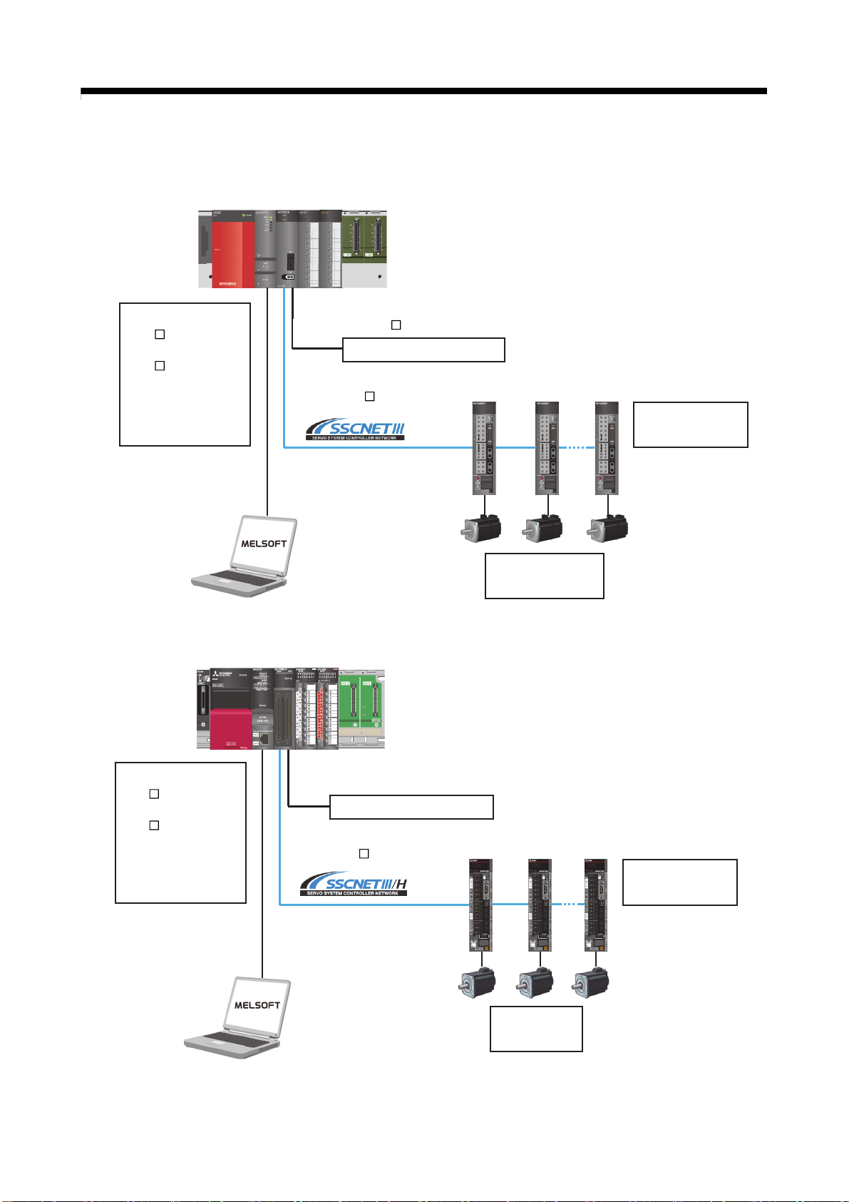
1.3 System Configuration
1.3.1 System configuration using QD74MH before migration
Main base unit
B
Q3
Power supply module
Q6
P
PLC CPU module
Qn(H)CPU
Positioning module
QD74MH
Forced stop input cable
Q170DEMICBL
Forced stop input (24 VDC)
SSCNETIII cable
MR-J3BUS
M(-A/-B)
M
USB communication
cable or RS-232
communication cable
Servo motor
HC/HA/HF series
1.3.2 System configuration using RD77MS after migration
Servo amplifier
MR-J3-B
Main base unit
B
R3
Power supply module
R6
P
PLC CPU module
RnCPU
Simple Motion module
RD77MS
USB communication
cable or Ethernet
communication cable
External in
SSCNETIII cable
MR-J3BUS
(Note-1): Replace the forced stop input cable for the new controller. (Refer to section 1.4.2.)
ut signal cable
Forced stop input (24 VDC)
M(-A/-B)
(Note-1)
Servo amplifier
Servo motor
HG series
MR-J4-B
1 - 4
Page 19
1. OVERVIEW OF MIGRATION FROM QD74MH TO RD77MS
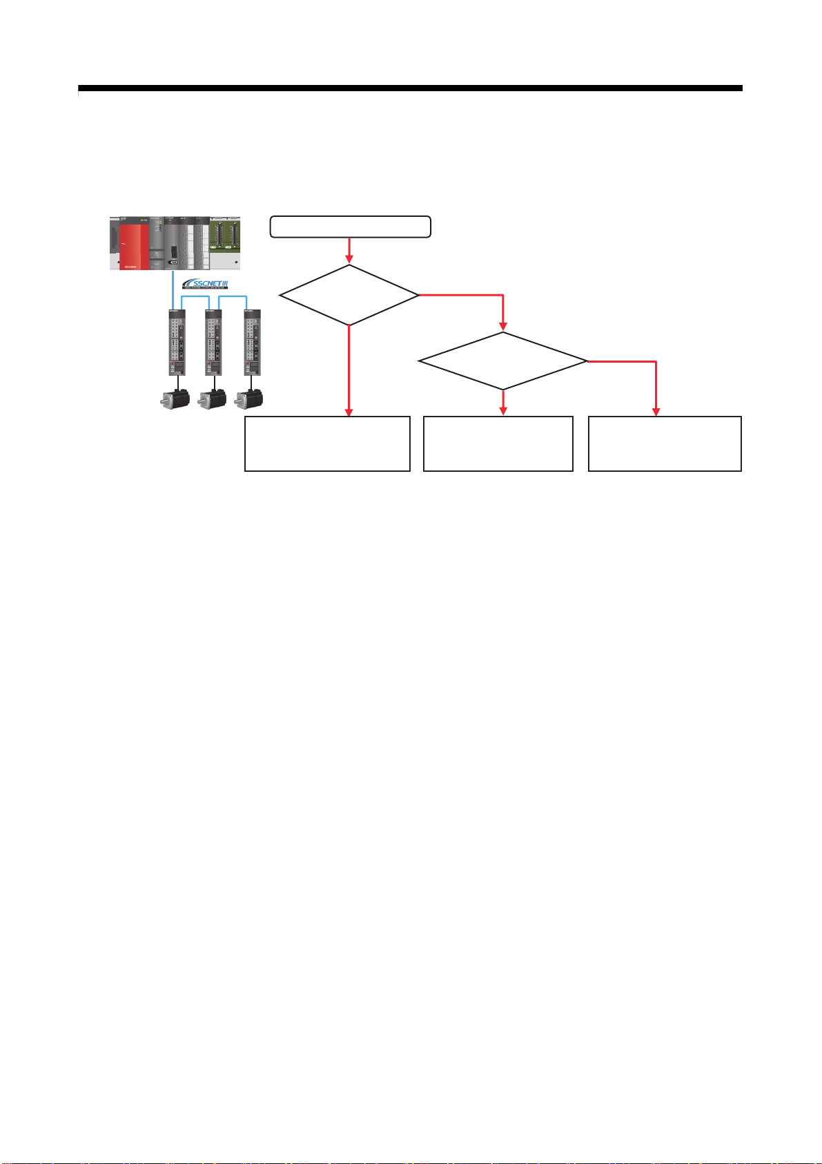
1.4 Case Study on Migration
The following describes a case study for migrating the existing system using QD74MH.
(1) Whole system migration (recommended)
The controller, servo amplifiers, servo motors, and servo system network are replaced
simultaneously. Although a large-scale installation is required, the whole system migration
allows the system to operate for longer periods. (Refer to section 1.4.1.)
(2) Phased migration (When the whole system migration is difficult due to the installation
period and cost.)
The controller is replaced with RD77MS in the first phase, and then the MR-J3-B servo
amplifiers are gradually replaced with MR-J4-B.
(Refer to section 1.4.2.)
(3) Separate repair
This is a replacement method for when the controller, the servo amplifier, or the servo motor
malfunctions.
(Refer to section 1.4.3.)
Consideration of migration
Whole system
migration?
YES
(1) Whole system migration
→ Refer to section 1.4.1.
NO
Phased
migration?
YES
(2) Phased migration
→ Refer to section 1.4.2.
NO
(3) Separate repair
→ Refer to section 1.4.3.
1 - 5
Page 20
1. OVERVIEW OF MIGRATION FROM QD74MH TO RD77MS
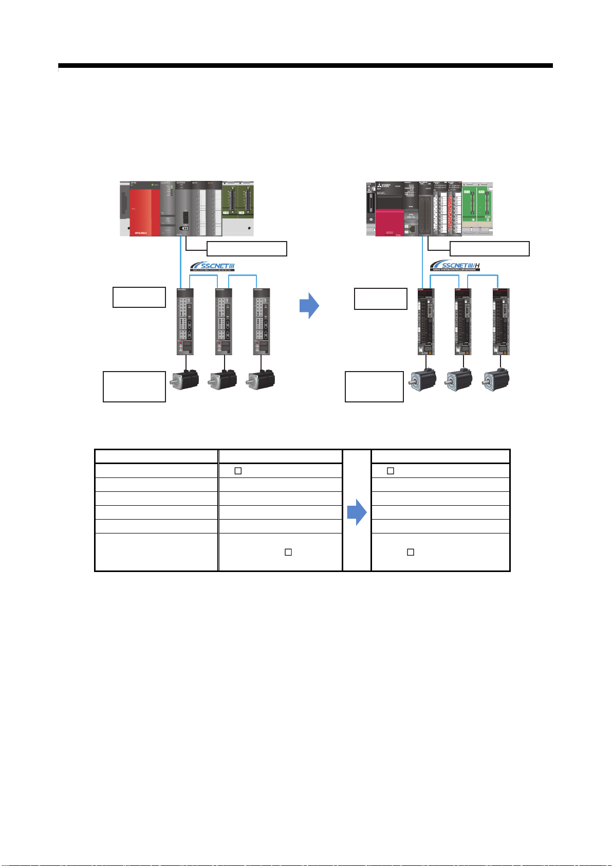
1.4.1 Whole system migration (recommended)
The following shows the system when the whole system migration takes place.
[Current model]
MR-J3-B
HC/HA/HF
servo motor
[Changes in the system]
Product name Model before migration
Main base unit Q3 B R3 B
PLC CPU module Qn(H)CPU RnCPU
Positioning module QD74MH RD77MS
Servo amplifier MR-J3-B MR-J4-B
Servo motor HC/HA/HF series HG series
Forced stop input cable
QD74MH
Forced stop input Forced stop input
Q170DEMICBL
M
[Model after migration]
MR-J4-B
HG
servo motor
Fabricate the cable with
A6CON connector.
(Refer to section 2.3.)
RD77MS
Model after migration
1 - 6
Page 21
r
r
1. OVERVIEW OF MIGRATION FROM QD74MH TO RD77MS
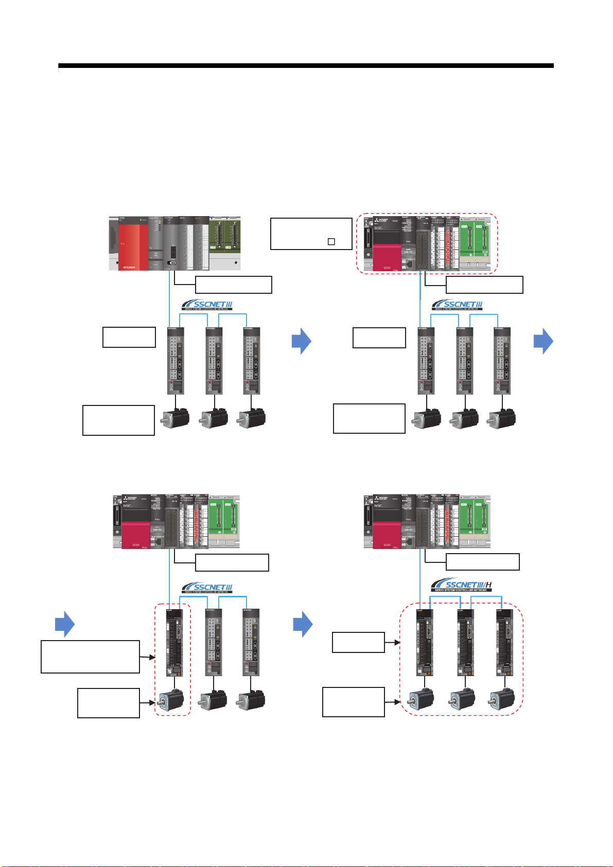
1.4.2 Phased migration
The following shows the procedure for the phased migration in which the controller is replaced
with RD77MS in the first phase, and then the MR-J3-B servo amplifiers are gradually replaced
with MR-J4-B in the following phases.
[Current model]
RD77MS
(RnCPU + R3
B)
Replacement - Phase 1]
[
Replacement of the controller
+ forced stop input cable
Forced stop input Forced stop input
MR-J3-B
MR-J3-B
HC/HA/HF
servo motor
HC/HA/HF
servo motor
[Replacement - Phase 2]
Servo amplifier and servo motor
replacement for only one axis
[Replacement - Phase 3]
Servo amplifier and servo motor replacement for all
axes, and servo system network replacement
Forced stop input
MR-J4-B
(J3 compatibility mode)
MR-J4-B
HG
servo moto
HG
servo moto
Forced stop input
(Note): For replacing only the servo amplifier or the servo
motor, refer to “1.4.3 Separate repair”.
(Note): For details of the J3 compatibility mode, refer to
“Transition from MELSERVO-J3/J3W Series to
J4 Series Handbook”.
(Note): When replacing all the servo amplifiers with
MR-J4-B, the operation mode can be switched
from “J3 compatibility mode” to “J4 mode”.
The servo system network is also changed from
SSCNETIII to SSCNETIII/H.
1 - 7
Page 22

1. OVERVIEW OF MIGRATION FROM QD74MH TO RD77MS
1.4.3 Separate repair
The following shows the procedure for the separate repair.
(1) When the controller has malfunctioned.
Replace only the controller.
MR-J3-B
HC/HA/HF servo motor
(2) When the MR-J3-B servo amplifier has malfunctioned.
Replace only the servo amplifier.
HC/HA/HF servo motor
R3 B
+RnCPU
+RD77MS
(Note):
MR-J3-B can operate with the replaced controller
The existing servo amplifiers and servo motors can
be used with the new controller.
Replacement with MR-J4-B
(J3 compatibility mode)
(Note):
For the compatible servo motors, refer to
“Transition from MELSERVO-J3/J3W
Series to J4 Series Handbook”.
1 - 8
Page 23

1. OVERVIEW OF MIGRATION FROM QD74MH TO RD77MS
(3) When the HC/HA/HF servo motor has malfunctioned
Simultaneously replace the servo amplifier and the malfunctioned servo motor.
Replacement with MR-J4-B
(J3 compatibility mode)
Replacement with HG servo motor
1 - 9
Page 24

1. OVERVIEW OF MIGRATION FROM QD74MH TO RD77MS
1.5 Project Diversion
The following describes about the project diversion for Qn(H)CPU and QD74MH setting software.
(1) PLC CPU projects
Be sure to recreate sequence programs for the migrated system
the buffer memory and the control method differs between QD74MH and RD77MS.
Refer to relevant manuals for details.
(2) Projects of QD74MH setting software (Japanese version only)
Projects in QD74MH setting software are partially divertible.
Refer to "2.4 Project diversion" for the procedure for project diversion.
because the structure of
1 - 10
Page 25

1. OVERVIEW OF MIGRATION FROM QD74MH TO RD77MS
1.6 Relevant Documents
Refer to the following relevant documents for the replacement.
1.6.1 Relevant catalogs
Servo System Controllers
MELSEC iQ-R/MELSEC iQ-F Series
SERVO AMPLIFIERS & MOTORS
MELSERVO-J4
L(NA)03100
Transition from MELSERVO-J3/J3W Series
to J4 Series Handbook
L(NA)03127
L(NA)03058
1 - 11
Page 26

1. OVERVIEW OF MIGRATION FROM QD74MH TO RD77MS
1.6.2 Relevant manuals
MELSEC iQ-R Simple Motion Module User's Manual (Startup)
MELSEC iQ-R Simple Motion Module User's Manual (Application)
MELSEC iQ-R Simple Motion Module User's Manual
(Advanced Synchronous Control)
RD77MS Before Using the Product
MR-J4-_B_(-RJ) SERVO AMPLIFIER INSTRUCTION MANUAL
MR-J4 Servo amplifier Instructions and Cautions for Safe Use of AC Servos
MELSERVO-J4 Servo amplifier INSTRUCTION MANUAL TROUBLE SHOOTING
(1) Simple Motion module
Manual title Manual No.
(2) Servo amplifier
Manual title Manual No.
IB-0300245
IB-0300247
IB-0300249
BCN-B62008-335E
SH-030106
IB-0300175E
SH-030109
MR-J4W2-_B/MR-J4W3-_B/MR-J4W2-0303B6 SERVO AMPLIFIER
INSTRUCTION MANUAL
SH-030105
1 - 12
Page 27

1. OVERVIEW OF MIGRATION FROM QD74MH TO RD77MS
MEMO
1 - 13
Page 28

1. OVERVIEW OF MIGRATION FROM QD74MH TO RD77MS
MEMO
1 - 14
Page 29

2. DETAILS OF MIGRATION FROM QD74MH TO RD77MS
2. DETAILS OF MIGRATION FROM QD74MH TO RD77MS
2.1 Table of Components and Software
Prepare Positioning modules, servo amplifiers, and an engineering environment according to the
following tables in this section.
Product name
Positioning module
Forced stop input cable Q170DEMICBL M A6CON1, A6CON2,A6CON4
Connector for forced stop
input cable
SSCNETIII cable
(Note-1): " " indicates the cable length.
(015: 0.15m, 03: 0.3m, 05: 0.5m, 1: 1m, 5: 5m, 10: 10m, 20: 20m, 30: 30m, 40: 40m, 50: 50m)
(Note-2): For a long distance cable of up to 100 m or an ultra-long bending life cable, contact Mitsubishi Electric System &
Service Co., Ltd.
[Sales office] FA PRODUCT DIVISION mail: osb.webmaster@melsc.jp
(Note-1)
QD74MH8
QD74MH16
Q170DEMICON
MR-J3BUS
MR-J3BUS
MR-J3BUS
Model
before migration
M
M-A
(Note-2)
M-B
Model
after migration
[Simple Motion module]
RD77MS8
RD77MS16
←(same as the left)
2
2 - 1
Page 30

2. DETAILS OF MIGRATION FROM QD74MH TO RD77MS
2.1.1 Servo amplifiers and servo motors
The servo system network is changed from SSCNETIII to SSCNETIII/H.
Select a SSCNETIII/H compatible servo amplifier and a servo motor connectable to the selected
servo amplifier.
(1) Servo amplifiers/Rotary servo motors
Before migration from QD74MH
Rotary
servo motor
HF-KP
HF-MP
HF-SP
HF-JP
HC-LP
HC-RP
HC-UP
HA-LP
MR-J3
series
Servo amplifier
MR-J3- B
MR-J3W-
MR-J3-
MR-J3- B-RJ006
B
BS
MR-J4
series
After migration to RD77MS
Servo amplifier
MR-J4-
MR-J4W2-
MR-J4W3-
B(-RJ)
B
B
Rotary
servo motor
HG-KR
HG-MR
HG-SR
HG-RR
HG-UR
HG-JR
(2) Servo amplifiers/Linear servo motors
Before migration from QD74MH
Linear
servo motor
LM-F
LM-K2
LM-U2
MR-J3
series
Servo amplifier
MR-J3- B-RJ004 LM-H2
After migration to RD77MS
Servo amplifier
MR-J4
series
MR-J4-
MR-J4W2- B
MR-J4W3-
B(-RJ)
B
Linear
servo motor
LM-H3
LM-F
LM-K2
LM-U2
2 - 2
Page 31

2. DETAILS OF MIGRATION FROM QD74MH TO RD77MS
Communications medium Optical fiber cable
Communications speed 50 Mbps 150 Mbps
Communications
cycle
Number of control axes
Transmission distance
(3) Comparison of servo system network
Item
Send
Receive
0.44 ms/0.88 ms
0.44 ms/0.88 ms
Up to 16 axes/line
[Standard code for inside panel]
Up to 3 m between stations
Maximum overall distance:
48 m (3 m × 16 axes)
[Standard cable for outside panel]
Up to 20 m between stations
Maximum overall distance:
320 m (20 m × 16 axes)
[Long distance cable]
Up to 50 m between stations
Maximum overall distance:
800 m (50 m × 16 axes)
(same as SSCNETIII)
←
0.222ms/0.444ms/0.888ms
0.222ms/0.444ms/0.888ms
(same as SSCNETIII)
←
[Standard code for inside panel and standard cable for
outside panel]
Up to 20 m between stations
Maximum overall distance: 320 m (20 m × 16 axes)
[Long distance cable]
Up to 100 m between stations
Maximum overall distance: 1600 m (100 m × 16 axes)
2.1.2 Engineering environment (required)
The engineering environment that supports RD77MS is as follows.
Product name Model Version
MELSOFT GX Works3 SW1DND-GXW3-E Ver.1.046Y or later
MELSOFT MR Configurator2 SW1DNC-MRC2-E Ver.1.27D or later
2 - 3
Page 32

2. DETAILS OF MIGRATION FROM QD74MH TO RD77MS
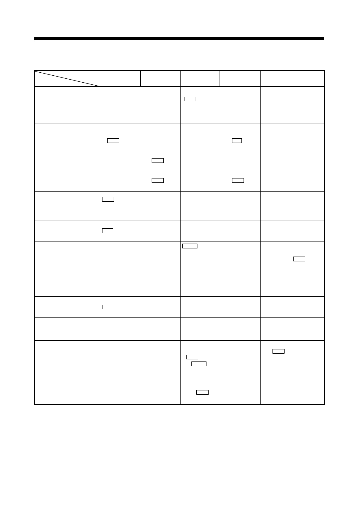
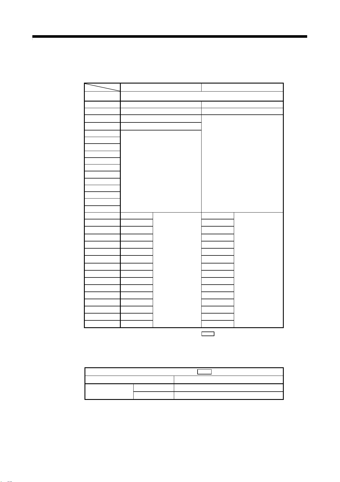
2.2 Differences Between QD74MH and RD77MS
(1) Performance and specifications
►
: An item in which the axis movement will be changed after migration.
Model
Item
Number of control axes
Operation cycle 0.88ms
QD74MH8 QD74MH16 RD77MS8 RD77MS16 Points for migration
8 16 8 16
♦
0.444ms/0.888ms/1.777ms/
3.555ms
An item that requires a setting change at migration.
−
The default value differs.
►
Pr.96
Set
to “0000H”.
Control
method
Starting time
(1 axis linear
interpolation)
Servo system network SSCNETIII SSCNETIII/H or SSCNETIII
Servo amplifier
Machine home position
return
(Home position return
method)
HP shift function
OP search limit function
Incremental feed operation
Synchronous Not provided Provided −
Trapezoidal
acceleration/
deceleration
S-curve
acceleration/
deceleration
MR-J3-
MR-J3-
Data set method, Stopper type,
Limit switch combined type,
Scale origin signal detection type)
• The speed during HP shift: the
value set in “
• Move for the set amount without
deceleration, even at zero point
signal.
6.0ms
6.5ms
B/MR-J3W- B/
BS/MR-J3W- B-RJ006/
MR-J3-
(Proximity dog method,
Dog cradle type,
B-RJ004
6 types
Pr.56 Creep speed”.
Provided
Provided Provided (Inching operation)
1.46ms (Operation cycle 0.888ms)
1.59ms (Operation cycle 1.777ms)
1.52ms (Operation cycle 3.555ms)
MR-J4-
MR-J4W2-
6 types
(Proximity dog method,
Count method1, Count method2,
Data set method, Scale home
position signal detection method,
Driver home position return method
• The speed during HP shift: Select
the value with either “ Pr.46 HPR
speed” or ”
• Decelerate to a stop at zero point
signal, and then accelerate again to
the specified speed to move for the
set shift distance.
(Note-1)
Pr.47 Creep speed”.
Not provided
B(-RJ)/
B/MR-J4W3- B
)
−
►Select a servo system
network which is
compatible with the
devices to be connected
such as servo amplifiers.
Pr.97 0: SSCNETIII
1: SSCNETIII/H
−
Stopper type, dog cradle
type, and limit switch
combined type are not
available with RD77MS
(Note-2)
.
►
♦ Set ” Pr.56 Speed
designation during HP
shift” to “1” (
Creep speed).
Pr.47
♦ The OP search limit
function is not available
with RD77MS
The operation name has
been changed.
(Note-2)
.
2 - 4
Page 33
2. DETAILS OF MIGRATION FROM QD74MH TO RD77MS
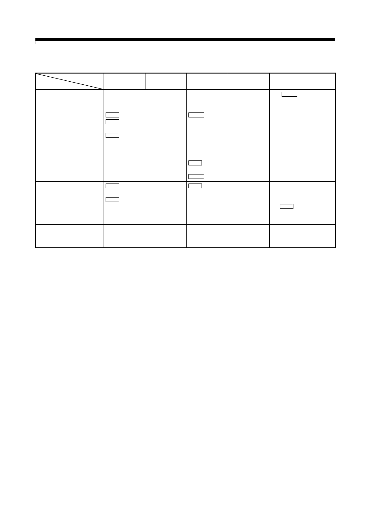
(Continued)
Model
Item
Linear interpolation control Speed: Combined-speed only
Speed limit value
Acceleration/deceleration
control
Sudden-stop control
Forced stop control
Pausing function
Parameter change request
Torque limit function
QD74MH8 QD74MH16 RD77MS8 RD77MS16 Points for migration
Select the command speed with
“
Pr.20 Interpolation speed
designation method”
0: Composite speed
1: Reference axis speed
[Linear interpolation control]
Composite speed:
Pr.26
Linear interpolation speed
limit value
Speed for each axis:
The limits are set with
Pr.10
limit value.
[Manual control]
The limits are set with
Pr.10
limit value.
Pr.16
S-curve
acceleration/deceleration time
[Linear interpolation control]
Speed for each axis:
The limits are set with
limit value.
Speed
[Manual control]
Speed
The limits are set with
speed limit value.
Not provided
constant
Cd.4
Axis sudden stop Not provided
Forced stop is executed by the signal
(Y2) from PLC CPU.
0: Forced stop release
1: Forced stop
Cd.158
Forced stop input
0000H: Forced stop ON (Forced
stop)
0001H: Forced stop OFF (Forced
stop release)
Cd.5
Pausing Not provided
Provided Not provided
Torque limit value: 0.1% unit
Controlled by the motor maximum
torque.
Torque limit value: 0.1% unit
Controlled by the value set in
Pr.17
Torque limit setting value”
“
Cd.101
or “
value”
However, when a home position
Torque output setting
return is being executed, the value
Pr.54
set in “
HPR torque limit value”
is applied.
Pr.8
Pr.31
Speed
JOG
♦ Composite speed cannot
be designated for 4-axis
linear interpolation
(Note-2)
♦ The composite speed
cannot be used for limiting
(Note-2)
speed
.
♦ The S-curve acceleration/
deceleration time
constant is not available
with RD77MS
(Note-2)
.
♦ The sudden-stop control
is not available with
RD77MS
►When the buffer memory
executes the forced stop
control, set “
Forced stop valid/invalid
selection” to “2”.
►Cannot be used with the
forced stop by 24 VDC
external input signal.
(Note-2)
.
Pr.82
♦ The pausing function is
not available with
RD77MS
(Note-2)
.
♦ The parameter change
function is not available
with RD77MS
♦The default value of
►
Pr.17 Torque limit
“
setting value” is
3000[0.1%].
Review the value
according to the motor to
be used.
(Note-2)
.
.
2 - 5
Page 34
2. DETAILS OF MIGRATION FROM QD74MH TO RD77MS
(Continued)
Model
Item
Torque change function
Acceleration/deceleration
time change function
Engineering environment
(Note-1): The home position return set in driver (servo amplifier) is used.
(Note-2): Contact your local sales office for details.
(Note-3): Only Japanese version is available for QD74MH setting software.
QD74MH8 QD74MH16 RD77MS8 RD77MS16 Points for migration
Torque limit value: 0.1% unit
Forward/reverse torque limit
value individual setting
Cd.11 Torque limit request
Cd.12 Forward rotation torque limit
value
Cd.13 Reverse rotation torque limit
value
Torque limit value: 0.1% unit
Forward/reverse torque limit
value same setting/individual setting
Cd.112 Torque change function
switching request
0: Forward/reverse torque
limit value same setting
1: Forward/reverse torque
limit value individual
setting
Cd.22 New torque value/forward
new torque value
Cd.113 New reverse torque value
Cd.18 Acceleration time change
request
Cd.20 Deceleration time change
request
Cd.12 Acceleration/deceleration
time change value during
speed change, enable/
disable
1: Enables modifications to
acceleration/deceleration time
MELSOFT GX Works2
QD74MH setting software
(Note-3)
MELSOFT GX Works3
(Simple Motion Module Setting
Function)
Cd.112 Torque change
Set “
function switching request”
to “1”.
►♦The acceleration/
deceleration time can be
changed by setting
Cd.12 .
−
2 - 6
Page 35

2. DETAILS OF MIGRATION FROM QD74MH TO RD77MS
(2) Exterior dimensions/mass/installation
QD74MH8 QD74MH16
QD74MH16
RUN
ERR.
498
RD77MS8 RD77MS16
RD77MS16
ERRRUN
AX1-16
Exterior
dimensions
[mm]
Mass [kg]
Internal
current
consumption
(5 VDC) [A]
CN1
EMI
QD74MH16
23
90
27.4
498
(Note) The connector for SSCNETIII cable is at the bottom of
the module.
98.0[H]×27.4[W]×90.0[D] 106.0[H]×27.8[W]×110.0[D]
0.15 0.23
0.70 1.0
Top ofpanel or wiring duct
RD77MS
RD77MS4
ERRRUN
3421
AX
AX
30 mm
or more
(Note-1)
Base unit
110
80 mm
or more
27.8
106
Door
70 mm
Panel
119 mm
or more
5mmormore
(Note-2)
5 mm or more
(Note-1): For wiring duct with 50mm or less height. For other cases, 40mm or more.
(Note-2): 20mm (0.79inch) or more when the adjacent module is not removed and the extension cable is connected.
2 - 7
Page 36

2. DETAILS OF MIGRATION FROM QD74MH TO RD77MS
(3) Operation cycle
The operation cycle settings of QD74MH can be imported to RD77MS when the projects of
QD74MH are diverted to RD77MS in MELSOFT GX Works3.
(Refer to section 2.4.1 for details of project diversion.)
However, if the operation cycle is set as default (automatic), the operation cycle will be
changed. Set an operation cycle where necessary by following the table below because the
change in the operation cycle may change program execution timing.
[Control axes and operation cycle at default]
Model
Item
Number of control axes
QD74MH RD77MS
Up to 16 Up to 16
Operation cycle
(default)
[Settable operation cycle]
QD74MH RD77MS
0.88ms
0.88ms
0.444ms
0.888ms
1.777ms
3.555ms
0.444ms/1 to 4 axes
0.888ms/5 to 8 axes
1.777ms/9 to 16 axes
2 - 8
Page 37

2. DETAILS OF MIGRATION FROM QD74MH TO RD77MS
(4) Parameter setting
Review the existing settings and sequence programs for the parameters, monitor
data, control data which do not exist in RD77MS.
Refer to manuals of each module for details.
(a) Parameter
QD74MH RD77MS Points for migration
Pr.2
Pr.0
Electronic gear numerator (AP)
1 to 32768
Pr.2
Electronic gear denominator (AL)
1 to 32768
Pr.4
Software stroke limit upper limit value
Number of pulses per rotation (AP)
1 to 200000000
Pr.3
Movement amount per rotation (AL)
1 to 200000000
Pr.12
Software stroke limit upper limit value −
An item that requires a setting change at migration
►
The setting range has been
changed.
Pr.6
Software stroke limit lower limit value
Pr.8
Backlash compensation amount
Pr.10
Speed limit value
1 to 2147 (Unit:×10
Pr.15
Acceleration/deceleration method
6
[PLS/s])
0: Linear acceleration/deceleration
1: S-curve acceleration/deceleration
Pr.16
S-curve acceleration/deceleration time
constant
Pr.17
Sudden stop deceleration time
0 to 20000
Pr.20
Command in-position range
0 to 2147483647
Pr.23
Target position change overrun processing
selection
Pr.25
Interpolation group
Pr.26
Linear interpolation speed limit value
Pr.31
External input signal logic selection
b0: Upper hardware stroke limit
b4: Lower hardware stroke limit
b8: Proximity dog
Pr.50
OPR method
0: Proximity dog
2: Data set
6: Scale origin signal detection
Pr.51
OPR direction
Pr.13
Software stroke limit lower limit value −
Pr.11
Backlash compensation amount −
Set the value multiplied by 10
Pr.8
Speed limit value
1 to 1000000000
Pr.31
JOG speed limit value
►
The setting range has been
changed.
Set the same value as
►
1 to 1000000000
Pr.34
Acceleration/deceleration process
selection
0: Trapezoid acceleration/deceleration process
1: S-curve acceleration/deceleration process
−
Pr.36
Rapid stop deceleration time
►If
1 to 8388608
If “0” is set, change it to “1”.
Pr.16
Command in-position width
►
1 to 2147483647
−
−
−
The layout of signals has been
Pr.22
Input signal logic selection
b0: Lower limit
►
changed.
b1: Upper limit
b6: Proximity dog signal
If “Data set method” or “Scale
Pr.43
HPR method
0: Proximity dog method
6: Data set method
►
origin signal detection method”
are set, change the setting.
7: Scale origin signal detection method
Pr.44
HPR direction −
Pr.8
−
−
“0” is set, change it to “1”.
−
−
−
6 .
.
Pr.52
OP address
Pr.45
HP address −
2 - 9
Page 38
2. DETAILS OF MIGRATION FROM QD74MH TO RD77MS
(Continued)
Pr.54
OPR speed
5 to 2147000000
Pr.56
Creep speed
5 to 32767
Pr.58
OPR acceleration time − −
Pr.59
OPR deceleration time − −
QD74MH RD77MS Points for migration
Pr.46
HPR speed
►
1 to 1000000000
Pr.47
Creep speed
1 to 1000000000
The setting range has been
changed.
If the current setting is outside of
the settable range of RD77MS,
review the setting.
Pr.60
OP shift amount
Pr.62
OP search limit
Pr.64
Incremental linear scale setting
Pr.66
Operation setting for incompletion of OPR
0: Not executed
1: Executed
Pr.53
HP shift amount −
− −
− −
Pr.55
Operation setting for incompletion of
HPR
0: Positioning control is not executed
1: Positioning control is executed.
Pr.80
JOG speed − −
Pr.82
JOG operation acceleration time − −
Pr.83
JOG operation deceleration time − −
Pr.84
Incremental feedrate − −
Pr.101
External forced stop selection
Pr.82
Forced stop valid/invalid selection −
−
2 - 10
Page 39

2. DETAILS OF MIGRATION FROM QD74MH TO RD77MS
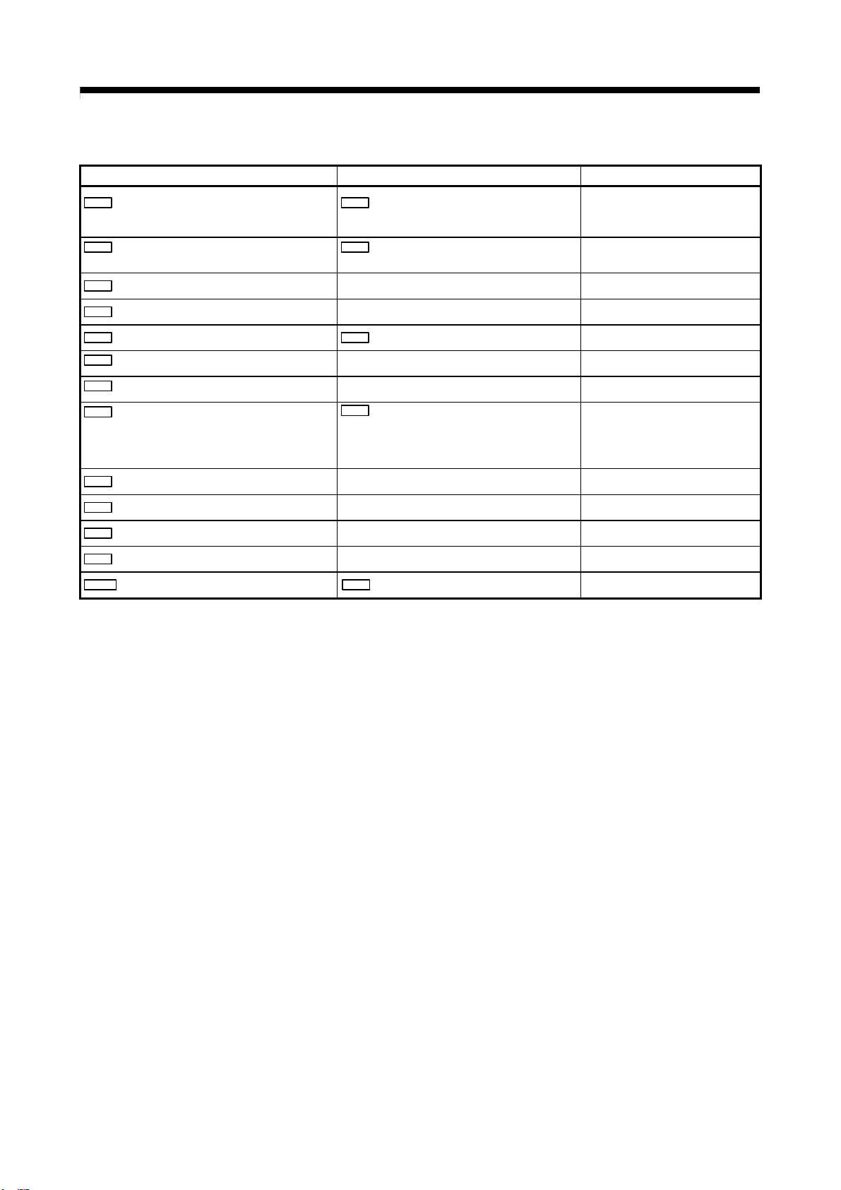
(b) Monitor data
An item that requires a setting change at migration
QD74MH RD77MS Points for migration
Md.0
Current feed value
Md.2
Feedrate
Md.4
External input signal
b0: Upper hardware stroke limit
b4: Lower hardware stroke limit
b8: Proximity dog
Md.5
Positioning data No. being executed
Md.6
Error code
Md.7
Error details − −
Md.8
Warning code
Md.9
Status 1
b0: OPR request
b1: OPR complete
Md.10
Status 2
b0: Positioning complete
b1: Command in-position
Md.26
Real current value
Md.28
Deviation counter value
Md.31
Motor current
Md.32
Motor rotation speed
Md.34
Regenerative load ratio
Md.35
Effective load torque ratio
Md.36
Peak torque ratio
Md.40
Servo status 1
b0: READY ON
b1: Servo ON
b7: Servo error (Servo alarm)
b12: In-position
b13: Torque limit
b14: Absolute position lost
b15: Servo warning
Md.41
Servo status 2
b0: Zero point pass
b3: Zero speed
Md.100
Axis error status − −
Md.101
Axis warning status − −
Md.102
Number of write accesses to flash ROM
Md.103
Forced stop input status
0: Forced stop
1: Forced stop release
Md.20
Feed current value −
Md.22
Feedrate −
Md.30
External input signal
b0: Lower limit signal
b1: Upper limit signal
b6: Proximity dog signal
Md.44
Positioning data No. being executed −
Md.23
Axis error No. −
Md.24
Axis warning No. −
Md.31
Status
b2 : Command in-position flag
b3 : HPR request flag
b4 : HPR complete flag
b15: Positioning complete
Md.101
Real current value −
Md.102
Deviation counter value −
Md.104
Motor current value −
Md.103
Motor rotation speed −
Md.109
Regenerative load ratio/Optional data
monitor output 1
Md.110
Effective load torque/Optional data
monitor output 2
Md.111
Peak torque ratio/Optional data monitor
output 3
Md.108
Servo status 1
b0: READY ON
b1: Servo ON
b7: Servo alarm
b12: In-position
b13: Torque limit
b14: Absolute position lost
b15: Servo warning
Md.119
Servo status 2
b0 : Zero point pass
b3 : Zero speed
Md.19
Number of write accesses to flash ROM −
Md.50
Forced stop input
0: Forced stop input ON (Forced stop)
1: Forced stop input OFF (Forced stop release)
►
The layout of input signals has
been changed.
Md.31
“
The servo status is 32-bit data
Status” is 16-bit data.
−
−
−
−
2 - 11
Page 40
2. DETAILS OF MIGRATION FROM QD74MH TO RD77MS
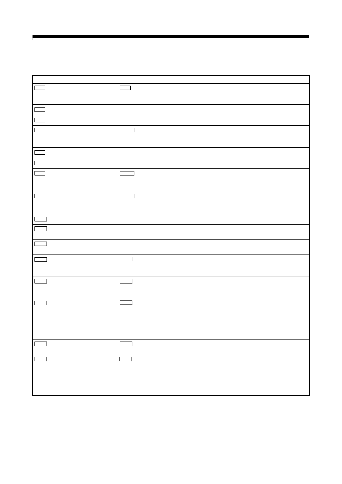
(c) Control data
An item that requires a setting change at migration
►
QD74MH RD77MS Points for migration
Cd.0
Axis error reset
0: Not commanded
Cd.5
Axis error reset
1: Axis error is reset.
Only “1: Axis error is reset” is
valid.
1: Commanded
Cd.1
Parameter change request − −
Cd.2
Start method − −
Cd.3
Axis stop
0: Not commanded
1: Commanded
Cd.4
Axis sudden stop − −
Cd.5
Pausing − −
Cd.8
Forward rotation JOG start
0: Stop
1: Start
Cd.9
Reverse rotation JOG start
0: Stop
1: Start
Cd.11
Torque limit request − −
Cd.12
Forward rotation torque limit
value
Cd.13
Reverse rotation torque limit
value
Cd.15
Speed change request
0: Not requested
Cd.180
Axis stop
1: Axis stop requested
Other than 1: Axis stop not requested
Cd.181
Forward run JOG start
1: JOG started
Other than 1: JOG not started
Cd.182
Forward run JOG start
1: JOG started
Other than 1: JOG not started
− −
− −
Cd.15
Speed change request
1: Executes speed change
Only “1: Axis stop requested” is
valid.
Only “1: JOG started” is valid.
Only “1: Change the speed is”
valid.
1: Requested
Cd.16
New speed value
5 to 2147000000
Cd.14
New speed value
0 to 1000000000
If the current setting is outside of
►
the settable range of RD77MS,
review the setting.
Cd.18
Acceleration time change request
0: Not requested
1: Requested
Cd.12
Acceleration/deceleration time change value
during speed change, enable/disable
1: Enables modifications to acceleration/deceleration
time
Other than 1: Disables modifications to acceleration/
Set this data to select whether
►
acceleration/deceleration time is
allowed to be modified or not
when a speed change is
executed.
deceleration time
Cd.19
New acceleration time value
0 to 20000
Cd.20
Deceleration time change request
0: Not requested
1: Requested
Cd.10
New acceleration time value
0 to 8388608
Cd.12
Acceleration/deceleration time change value
during speed change, enable/disable
1: Enables modifications to acceleration/deceleration
time
Other than 1: Disables modifications to acceleration/
The setting range has been
changed.
Set this data to select whether
►
acceleration/deceleration time
is allowed to be modified or not
when a speed change is
executed.
deceleration time
2 - 12
Page 41

2. DETAILS OF MIGRATION FROM QD74MH TO RD77MS
(Continued)
Cd.21
New deceleration time value
0 to 20000
Cd.23
Target position change request
0: Not requested
1: Requested
Cd.24
New target position value
QD74MH RD77MS Points for migration
Cd.11
New deceleration time value
0 to 8388608
Cd.29
Target position change request flag
1: Requests a change in the target position
Cd.27
Target position change value (New address) −
The setting range has been
changed.
Only “1: requests a change in the
target position” is valid.
Cd.28
New current value
Cd.30
Each axis servo OFF
0: Not commanded
1: Commanded
Cd.45
Semi/Fully closed loop switching
request
(When MR-J3-
Cd.46
Gain changing request
B-RJ006 is used)
0: Not requested
1: Requested
Cd.100
Flash ROM write request
0: Not requested
1: Requested
Cd.101
Parameter initialization request
0: Not requested
1: Requested
Cd.9
New current value −
Cd.100
Servo OFF command
0: Servo ON
1: Servo OFF
Valid only during “servo ON for all axes”.
Cd.133
Semi/Fully closed loop switching request
Cd.108
Gain switching command flag
0: Gain switching command OFF
1: Gain switching command ON
Cd.1
Flash ROM write request
1: Requests write access to flash ROM.
Cd.2
Parameter initialization request
1: Requests parameter initialization
−
−
−
−
−
2 - 13
Page 42
2. DETAILS OF MIGRATION FROM QD74MH TO RD77MS
(5) I/O signals
(a) Signal direction: Positioning module (Simple Motion module) → PLC CPU
QD74MH RD77MS
Device No. Signal name
X0 Unit READY
X1 Error detection
X2 Warning detection
X3 Synchronization flag
X4
X5
X6
X7
X8
X9
XA
Unusable
XB
XC
XD
XE
XF
X10 Axis 1
X11 Axis 2 Axis 2
X12 Axis 3 Axis 3
X13 Axis 4 Axis 4
X14 Axis 5 Axis 5
X15 Axis 6 Axis 6
X16 Axis 7 Axis 7
X17 Axis 8 Axis 8
X18 Axis 9 Axis 9
X19 Axis 10 Axis 10
X1A Axis 11 Axis 11
X1B Axis 12 Axis 12
X1C Axis 13 Axis 13
X1D Axis 14 Axis 14
X1E Axis 15 Axis 15
X1F Axis 16 Axis 16
(Note-1): These signals are included in the buffer memory “
(Note-2): There are some devices that will become “Use prohibited” after replacing the existing model
with RD77MS. The device No. with “Use prohibited” are used by system. Therefore, a user
cannot use them. In the case of using them, the operation is not guaranteed.
RD77MS buffer memory “
Buffer memory address Signal name
2417+100n
b9 Axis warning detection
b13 Error detection
(Note-1)
(Note-1)
BUSY
Md.31
RD77MS READY
Synchronization flag
Use prohibited
Axis 1
Md.31
Status” in RD77MS.
Status”
(Note-2)
BUSY
n: Axis No.-1
2 - 14
Page 43

2. DETAILS OF MIGRATION FROM QD74MH TO RD77MS
(b) Signal direction: PLC CPU → Positioning module (Simple Motion module)
QD74MH RD77MS
Device No. Signal name
Y0 PLC READY
Y1 All axis servo ON
Y2 Forced stop input
(Note-1)
Y3
Y4
Y5
Y6
Y7
Y8
Y9
Unusable
YA
YB
YC
YD
YE
YF
Y10 Axis 1
Y11 Axis 2 Axis 2
Y12 Axis 3 Axis 3
Y13 Axis 4 Axis 4
Y14 Axis 5 Axis 5
Y15 Axis 6 Axis 6
Y16 Axis 7 Axis 7
Y17 Axis 8 Axis 8
Y18 Axis 9 Axis 9
Positioning start
Y19 Axis 10 Axis 10
Y1A Axis 11 Axis 11
Y1B Axis 12 Axis 12
Y1C Axis 13 Axis 13
Y1D Axis 14 Axis 14
Y1E Axis 15 Axis 15
Y1F Axis 16 Axis 16
(Note-1): These signals are included in the buffer memory “
(Note-2): There are some devices that will become “Use prohibited” after replacing the existing model
with RD77MS. The device No. with “Use prohibited” are used by system. Therefore, a user
cannot use them. In the case of using them, the operation is not guaranteed.
RD77MS
Buffer memory address Setting value
5945
buffer
memory “
Cd.158
Forced stop input”
Set the forced stop information to the buffer memory.
0: Forced stop ON (Forced stop)
1: Forced stop OFF (Forced stop release)
A value other than "1" is regarded as "0".
Use prohibited
Axis 1
Positioning start
Cd.158
Forced stop input” in RD77MS.
(Note-2)
2 - 15
Page 44

2. DETAILS OF MIGRATION FROM QD74MH TO RD77MS
(6) Items that need a review or a change following the servo system network change
Items
Electronic
gear
Positioning
data
QD74MH RD77MS
Differences
− −
− −
Change “
Movement amount per rotation” of the basic parameter 1
according to the resolution per the connected servo
motor rotation.
Review the positioing data while taking into account the
differences in resolution per the connected servo motor
rotation and the setting changes in the electronic gear
above.
Change/revision
Pr.2
Number of pulses per rotation” and “
Pr.3
2 - 16
Page 45
2. DETAILS OF MIGRATION FROM QD74MH TO RD77MS
2.3 Forced Stop Input Cable
The forced stop input cable needs to be replaced along with the controller replacement.
(1) Cable replacement (recommended)
The existing forced stop cable (Q170DEMICBL
external input connection connector for RD77MS. To use the forced stop function with
RD77MS, fabricate the cable with the following connectors and cables.
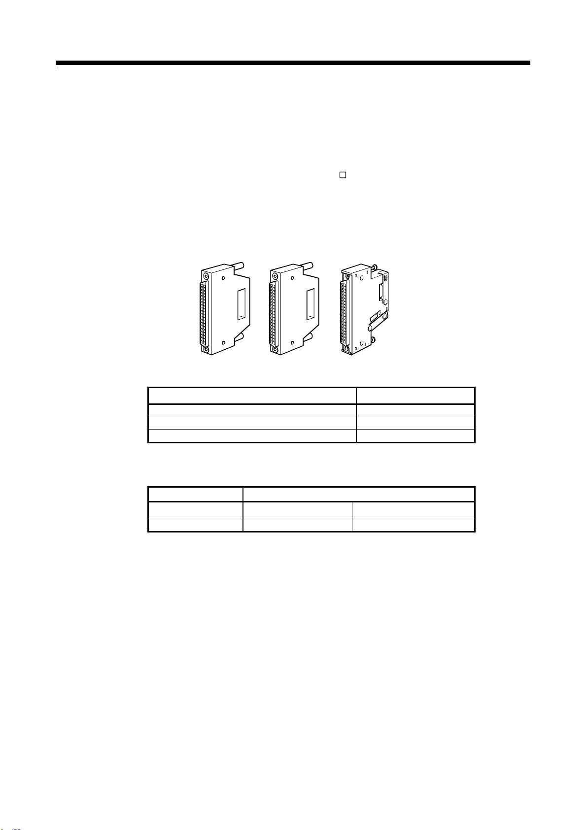
(a) Appearance
A6CON1 A6CON2 A6CON4
M) for QD74MH is not compatible with the
(b) Connector type
Type Model
Soldering type, useable for straight out A6CON1
Crimp-contact type, useable for straight out A6CON2
Soldering type, useable for straight out and diagonal out A6CON4
(c) Specifications of the connector
Part name Specification
Applicable connector A6CON1, A6CON4 A6CON2
Applicable wire size 0.3 mm2 AWG28 to 24
(Note): The external input wiring connector is not included. Please purchase them by customer.
[Specialized tool]
- Pressure-bonding tool for A6CON2 (Fujitsu component LTD.):
Model name: FCN-363T-T005/H
Contact: http://www.fujitsu.com/jp/group/fcl/en/
2 - 17
Page 46
f
2. DETAILS OF MIGRATION FROM QD74MH TO RD77MS
Pin layout
B20
B19
B18
B17
B16
B15
B14
B13
B12
B11
B10
B9
B8
B7
B6
B5
B4
B3
B2
B1
Front view o
the module
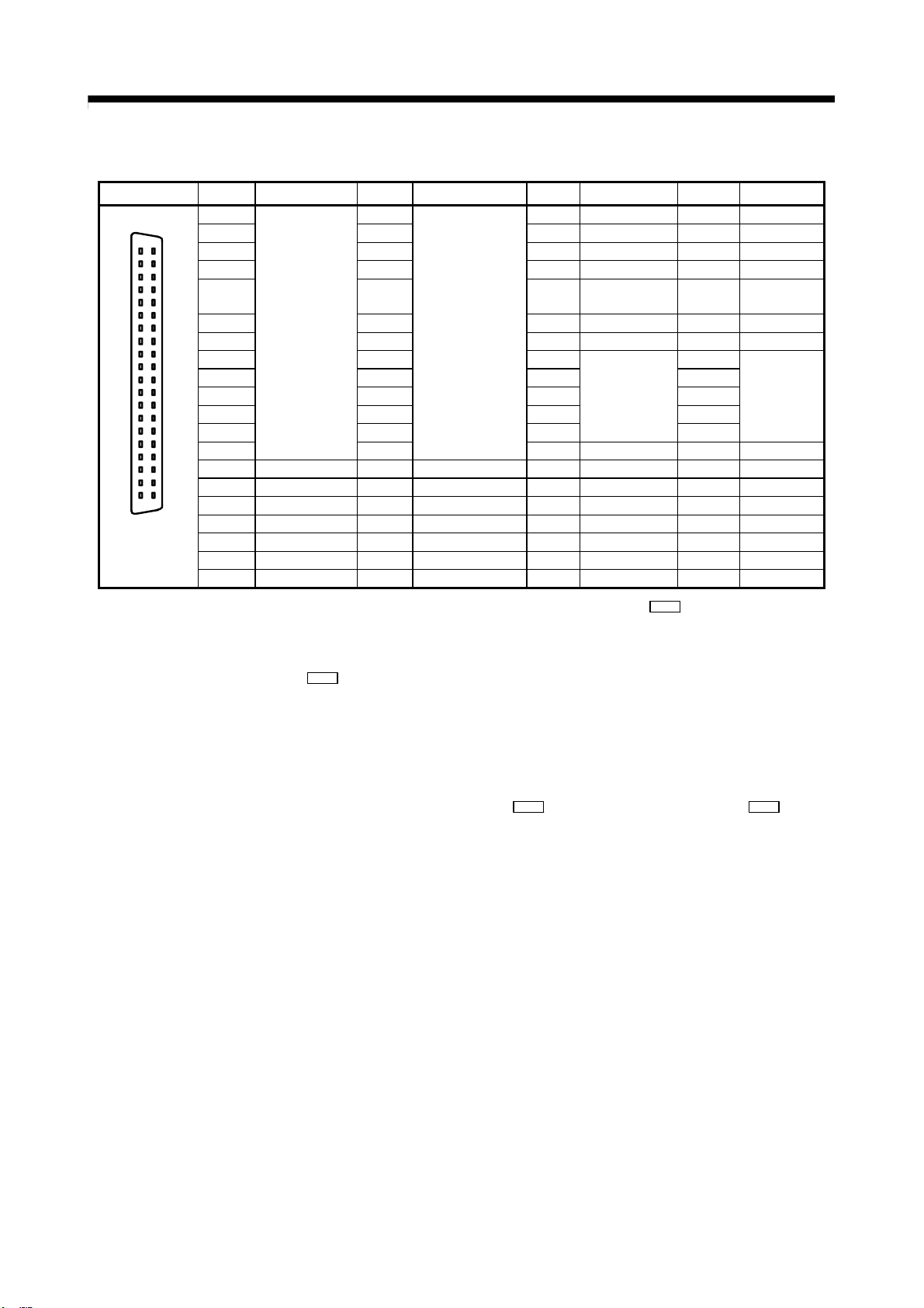
(Note-1): Input type from manual pulse generator/incremental synchronous encoder is switched in " Pr.89 Manual pulse generator/
Incremental synchronous encoder input type selection". (Only the value specified against the axis 1 is valid.)
• 0: Differential-output type
• 1: Voltage-output/open-collector type (Default value)
(Note-2): Set the signal input form in "
(Note-3): Voltage-output/open-collector type
Connect the A-phase/PLS signal to HA, and the B-phase/SIGN signal to HB.
(Note-4): Differential-output type
Connect the A-phase/PLS signal to HAH, and the A-phase/PLS inverse signal to HAL.
Connect the B-phase/SIGN signal to HBH, and the B-phase/SIGN inverse signal to HBL.
(Note-5): Do not connect to any of the terminal explained as "No connect".
(Note-6): Set the external command signal [DI, FLS, RLS, DOG, STOP] in "
command signal selection" at RD77MS use.
(Note-7): Do not use 1A20, 1A19, 1A(B)15, and 1A(B)14 for other than the power supply of manual pulse generator.
The signal layout for the external input connection connector of RD77MS is shown below.
Pin No. Signal name Pin No. Signal name Pin No. Signal name Pin No. Signal name
2B20
2A20
1B20 HB
2B19 2A19 1B19 HA
A20
2B18 2A18 1B18 HBL
A19
2B17 2A17 1B17 HAL
A18
A17
2B16 2A16 1B16
A16
A15
2B15 2A15 1B15 5V
A14
A13
2B14 2A14 1B14 SG
A12
2B13 2A13 1B13
A11
2B12 2A12 1B12 1A12
A10
A9
2B11 2A11 1B11 1A11
A8
2B10 2A10 1B10 1A10
A7
A6
2B9 2A9 1B9 1A9
A5
2B8 2A8 1B8 EMI.COM 1A8 EMI
A4
2B7 COM 2A7 COM 1B7 COM 1A7 COM
A3
A2
2B6 COM 2A6 COM 1B6 COM 1A6 COM
A1
2B5 SIN20
2B4 SIN19
2B3 SIN18
2B2 SIN17
2B1 SIN16
No connect
(Note-5)
(Note-6)
2A5 SIN15
(Note-6)
2A4 SIN14
(Note-6)
2A3 SIN13
(Note-6)
2A2 SIN12
(Note-6)
2A1 SIN11
Pr.24 Manual pulse generator/Incremental synchronous encoder input selection".
No connect
(Note-5)
(Note-6)
(Note-6)
(Note-6)
(Note-6)
(Note-6)
1B5 SIN10
1B4 SIN9
1B3 SIN8
1B2 SIN7
1B1 SIN6
Pr.80 External input signal selection" and " Pr.95 External
(Note-1, 2, 3)
(Note-1, 2, 3)
(Note-1, 2, 4)
(Note-1, 2, 4)
No connect
(Note-5)
(Note-7)
(Note-7)
No connect
(Note-5)
(Note-6)
(Note-6)
(Note-6)
(Note-6)
(Note-6)
1A20 5V
1A19 5V
1A18 HBH
1A17 HAH
1A16
1A15 5V
1A14 SG
1A13
1A5 SIN5
1A4 SIN4
1A3 SIN3
1A2 SIN2
1A1 SIN1
(Note-7)
(Note-7)
(Note-1, 2, 4)
(Note-1, 2, 4)
No connect
(Note-5)
(Note-7)
(Note-7)
No connect
(Note-5)
(Note-6)
(Note-6)
(Note-6)
(Note-6)
(Note-6)
2 - 18
Page 47
2. DETAILS OF MIGRATION FROM QD74MH TO RD77MS
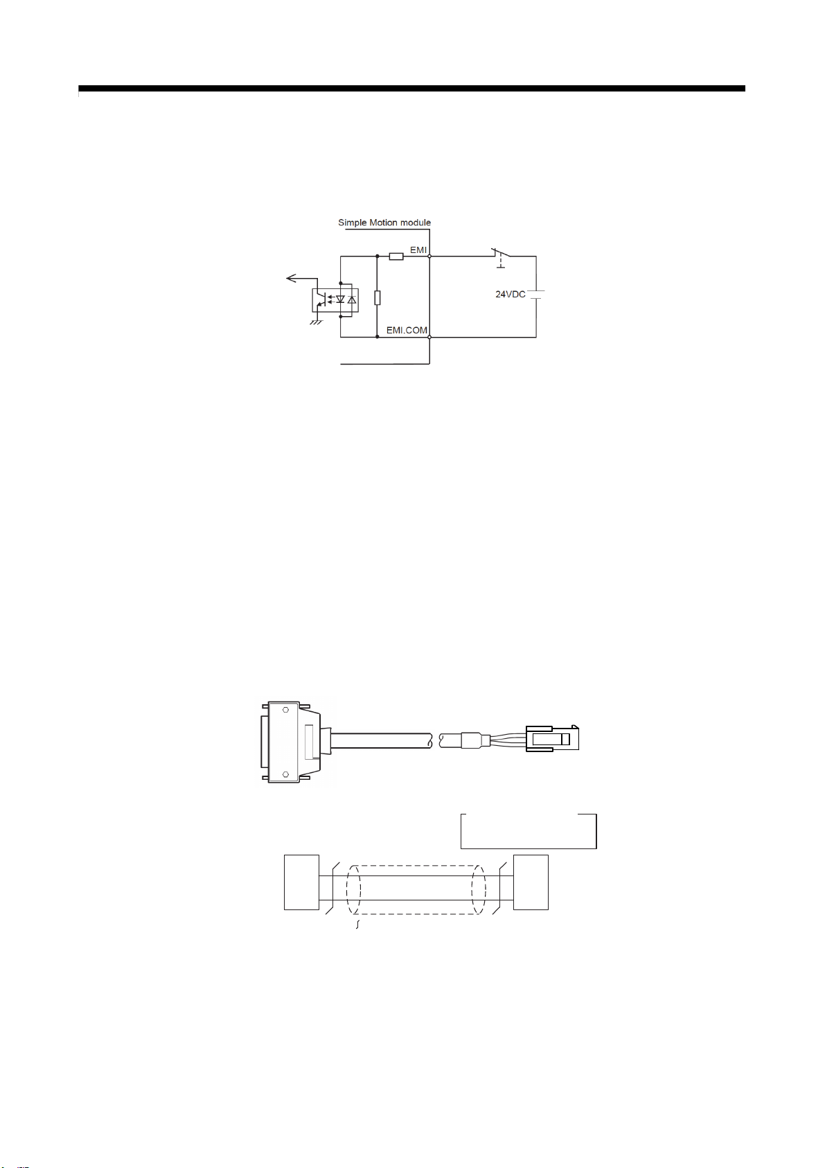
When using the forced stop function, wire the terminals of the Simple Motion module forced
stop input (1A08/1B08) as shown below. As for the 24VDC power supply, the direction of
current can be switched.
(2) Conversion connector
When using the forced stop input cable (Q170DEMICBL
conversion cable with the A6CON connector and the receptacle below.
Use the cable whose wire size is AWG24.
(a) A6CON connector (RD77MS side)
Use the connector in “(1) Cable replacement (recommended)”.
(b) Receptacle (Forced stop input cable side)
Fabricate the receptacle by combining the following housing and terminal.
Housing : 5559-02P-210 (Manufacturer: Molex Incorporated)
Terminal : 5558PBTL (Manufacturer: Molex Incorporated)
RD77MS side
(1A_ _, 1B_ _)
Q170DEMICBL□M side
□
M) for RD77MS, fabricate the
Rec epta cle con nector
EMI.COM
EMI
A6CON
1B8
1A8
・5558 PB TL
・5559 -02 P-21 0
:Twisted pair cable
(N ot e): Use a 24 AWG cable .
(Terminal)
(Hous in g)
2
1
2 - 19
Page 48

2. DETAILS OF MIGRATION FROM QD74MH TO RD77MS
2.4 Project Diversion
2.4.1 Project diversion procedures by engineering environment
(1) Procedures for diversion of QD74MH setting software data by MELSOFT GX Works3
The following shows the diversion procedure.
1) Start MELSOFT GX Works3.
2) Select “New” in “Project” menu to create a new MELSEC iQ-R series project.
3) Select “Add New Module” from “Module Information” under “Parameter” in the navigation
tree. A new module can also be added on “Module Configuration” screen from the
navigation tree.
2 - 20
Page 49

2. DETAILS OF MIGRATION FROM QD74MH TO RD77MS
4) On the “Add New Module” screen, select “Simple Motion” for [Module Type], the replaced
Simple Motion module model for [Module Name] (the setting example below: RD77MS16),
and then set each item in "Mounting Position" of "Advanced Settings" according to your
system.
Click “OK”.
5) The module label setting confirmation screen will appear. Change the setting where
necessary and click "OK".
2 - 21
Page 50
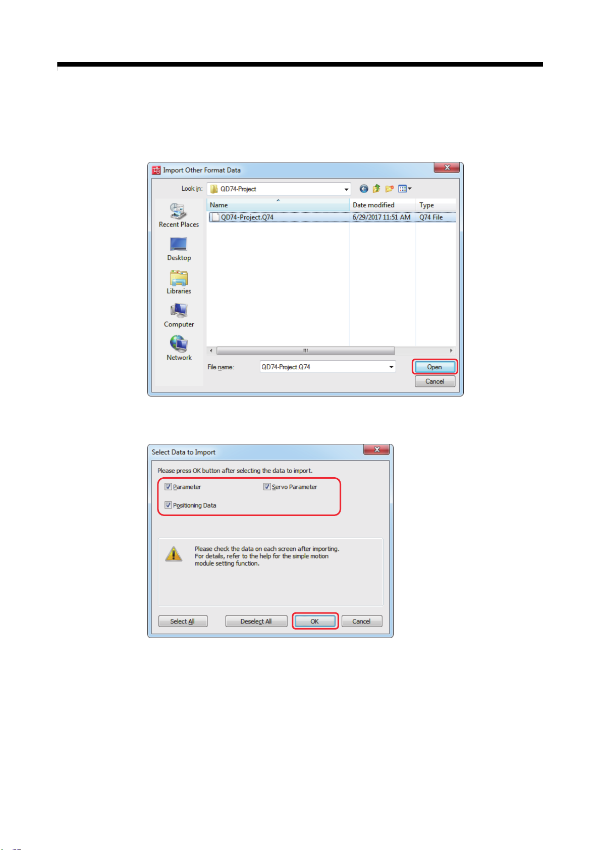
2. DETAILS OF MIGRATION FROM QD74MH TO RD77MS
6) Right-click on the new module name (in this example, “RD77MS16” set in 4)) in “Module
Information” in the navigation tree, and select [Import Other Format Data].
7) Select the project files to be diverted in QD74MH setting software, and click “Open”.
8) Select data to import on “Select Data to Import” screen, and click “OK”.
2 - 22
Page 51

2. DETAILS OF MIGRATION FROM QD74MH TO RD77MS
9) Execute the series conversion of the servo amplifier. Select the network to be used for the
replaced servo amplifiers (for RD77MS), and click [OK].
(Note): When servo parameters settings are changed from “MR-J3 series” to “MR-J4 series”, the parameter
conversion is carried out based on conversion rules.
Refer to “Simple Motion Module Setting Help [Appendix] - [Servo parameter conversion]” for the
conversion rules.
10) When the project diversion completion message appears, click “OK”. Be sure to check the
imported data.
The diversion is completed.
Before writing to the Simple Motion module, be sure to confirm the validity of the
diverted parameters.
(2) Sequence programs
The structure of buffer memory and the control method differs between QD74MH and
RD77MS.
Be sure to recreate sequence programs for the new system.
2 - 23
Page 52
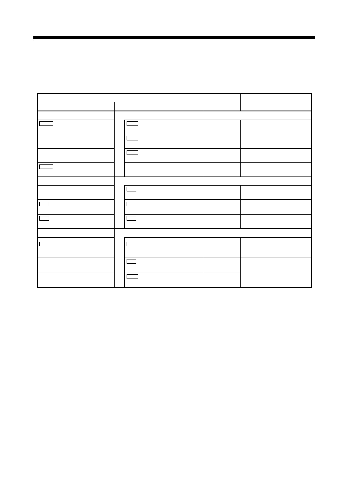
2. DETAILS OF MIGRATION FROM QD74MH TO RD77MS
2.4.2 List of divertible/not divertible data
(1) Module parameters
Pr.101
External forced stop selection
ᅳ
ᅳ
Pr.102
Error and warning history selection
ᅳ
Pr.0
Electronic gear numerator (AP)
Pr.2
Electronic gear denominator (AL)
Pr.10
Speed limit value
ᅳ
ᅳ
The initial values are set for parameters not listed in the table below
Data name
QD74MH RD77MS
Common parameters
Pr.82
Forced stop valid/invalid selection
Pr.96
Operation cycle setting
Pr.97
SSCNET setting
ᅳ
Basic parameters 1
Pr.1
Unit setting
Pr.2
Number of pulses per rotation (AP)
Pr.3
Movement amount per rotation (AL)
Basic parameters 2
Pr.8
Speed limit value
Pr.9
Acceleration time 0
Pr.10
Deceleration time 0
Divertible or
not divertible
◯
ᅳ
ᅳ
×
ᅳ
◯
◯
◯
◯
◯
.
Remarks
ᅳ
“0000H: 0.888ms” is set.
The value selected in SSCNET
setting at replacement will be set.
Error and warning histories are
automatically saved.
“3: pulse” is set.
ᅳ
ᅳ
The value that multiplies
QD74MH setting value by
1000000 is set.
These acceleration/deceleration
time values come from the
positioning data.
(Refer to (2) in this section)
2 - 24
Page 53

2. DETAILS OF MIGRATION FROM QD74MH TO RD77MS
(Continued)
Data name
QD74MH RD77MS
Detailed parameters 1
Pr.8
Backlash compensation amount
Pr.20
Command in-position range
Pr.16
S-curve acceleration/deceleration
time constant
Pr.23
Target position change overrun
processing selection
Pr.25
Interpolation group
Pr.26
Linear interpolation speed limit
value
Pr.28
Feed current value update selection
during speed-torque control
Pr.31
External input signal logic selection:
Lower limit
Pr.31
External input signal logic selection:
Upper limit
Pr.31
External input signal logic selection:
Proximity dog
Pr.11
Backlash compensation amount
Pr.16
Command in-position width
ᅳ
ᅳ
ᅳ
ᅳ
ᅳ
Pr.22
Input signal logic selection: Lower
limit
Pr.22
Input signal logic selection: Upper
limit
Pr.22
Input signal logic selection:
Proximity dog signal
Divertible or
not divertible
◯
◯
×
×
×
×
×
◯
◯
◯
Remarks
ᅳ
ᅳ
ᅳ
ᅳ
ᅳ
ᅳ
ᅳ
ᅳ
ᅳ
ᅳ
2 - 25
Page 54

2. DETAILS OF MIGRATION FROM QD74MH TO RD77MS
(Continued)
Data name
QD74MH RD77MS
Detailed parameters 2
ᅳ
Pr.82
JOG operation acceleration time
Pr.58
OPR acceleration time
ᅳ
Pr.83
JOG operation deceleration time
Pr.59
OPR deceleration time
Pr.10
Speed limit value
ᅳ
Pr.25
Acceleration time 1
Pr.26
Acceleration time 2
Pr.27
Acceleration time 3
Pr.28
Deceleration time 1
Pr.29
Deceleration time 2
Pr.30
Deceleration time 3
Pr.31
JOG speed limit value
Pr.32
JOG operation acceleration time
selection
Pr.33
ᅳ
JOG operation deceleration
time selection
Pr.15
Acceleration/deceleration method
Pr.17
Sudden stop deceleration time
ᅳ
Pr.80
JOG speed
Pr.84
Incremental feedrate
Pr.34
Acceleration/deceleration process
selection
Pr.36
Rapid stop deceleration time
Pr.37
Stop group 1 rapid stop selection
×
ᅳ
×
ᅳ
Divertible or
not divertible
◯
◯
◯
◯
◯
◯
◯
ᅳ
ᅳ
◯
◯
ᅳ
Remarks
The acceleration time value
comes from positioning data.
(Refer to (2) in this section)
ᅳ
ᅳ
The deceleration time value
comes from positioning data.
(Refer to (2) in this section)
ᅳ
ᅳ
The value that multiplies
QD74MH setting value by
1000000 is set.
“2” is set.
ᅳ
ᅳ
“1: Rapid stop” is set.
ᅳ
ᅳ
2 - 26
Page 55

2. DETAILS OF MIGRATION FROM QD74MH TO RD77MS
(Continued)
Data name
QD74MH RD77MS
HPR basic parameters
Pr.50
OPR method
Pr.51
OPR direction
Pr.52
OP address
Pr.54
OPR speed
Pr.56
Creep speed
ᅳ
Pr.43
HPR method
Pr.44
HPR direction
Pr.45
HP address
Pr.46
HPR speed
Pr.47
Creep speed
Pr.48
HPR retry
HPR detailed parameters
ᅳ
ᅳ
Pr.60
OP shift amount
Pr.66
Operation setting for incompletion
of OPR
ᅳ
Pr.62
OP search limit
Pr.64
Incremental linear scale setting
Pr.51
HPR acceleration time selection
Pr.52
HPR deceleration time selection
Pr.53
HP shift amount
Pr.55
Operation setting for incompletion of
HPR
Pr.56
Speed designation during HP shift
ᅳ
ᅳ
Divertible or
not divertible
◯
◯
◯
◯
◯
ᅳ
ᅳ
ᅳ
◯
◯
ᅳ
×
×
Remarks
The current values are converted
as follow.
“0”→“0”
“2”→“6”
“3”→“0”
“4”→“0”
“5”→“0”
“6”→“7”
“7”→“0”
(Note): The initial values are set
for values other than
above.
ᅳ
ᅳ
ᅳ
ᅳ
The OPR settings of QD74MH
are diverted as follows according
Pr.50
to the value set in “
method”
“0” or “4” has been set:
OPR
“1: Retry HPR with limit
switch”
Other than above:
0: Do not retry HPR with
“
limit switch
“3” is set.
”
ᅳ
ᅳ
“1: Creep speed” is set.
ᅳ
ᅳ
2 - 27
Page 56
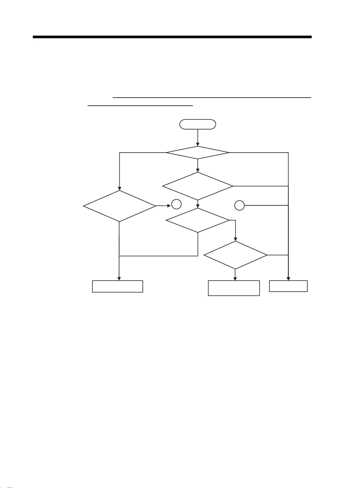
p
2. DETAILS OF MIGRATION FROM QD74MH TO RD77MS
(2) Positioning data
(a) Although QD74MH positioning data is not compatible with RD77MS, some data can be
converted for the new system.
However,
data needs to be reviewed and revised.
make sure that it is not fully diverted for the new system. The positioning
START
Linear interpolation
Has the
interpolation group
been set?
No
All data is divertible. Not divertible
Yes
Control method?
Has the
interpolation group
been set?
1
The reference
axis setting?
Inter
Yes
Yes
Only positioning address
Other control methods
olation control
No
No
Has the
interpolation
axis been set?
is divertible.
1
No
Yes
2 - 28
Page 57

2. DETAILS OF MIGRATION FROM QD74MH TO RD77MS
(b) The following shows the details of positioning data diversion.
1) The existing acceleration/deceleration time settings are diverted to “
time 0”, “
Pr.25
Acceleration time 1”/“
Pr.10 :
Deceleration time 0”, “
time 1”.
2) The control method “6: Speed-torque” is not divertible. Create a sequence program by
referring to “MELSEC iQ-R Simple Motion Module User's Manual (Application)”.
3) When the control method is set as either “2: ABS linear interpolation” or “3: INC linear
interpolation”, the lowest axis No. in the interpolation group will be set as the reference
axis.
) Among the positioning data of axes specified in “
4
ones in which “2: ABS linear interpolation” or “3: INC linear interpolation” is set can be
diverted.
However, if the control methods do not match among the axes, the positioning data will
QD74MH RD77MS
Operation pattern Operation pattern
Control method Control method
Interpolation axes
ᅳ
Acceleration time No.
ᅳ
Acceleration time/torque time
constant
Deceleration time No. Refer to (b)-1) above.
ᅳ
Deceleration time
Positioning address/
torque command value
Arc address
ᅳ
Command speed/speed limit
value
Dwell time Dwell time
M-code
ᅳ
ᅳ
ᅳ
ᅳ
Comments in positioning data
ᅳ
Positioning data No.2 to No.32 Positioning data No.2 to No.32
not be diverted.
Data name
ᅳ
ᅳ
Positioning address
Command speed
M code ON signal output timing
ABS direction in degrees
Interpolation speed designation
method
Divertible or
not divertible
○: Divertible,×: Not divertible
(Note-1): These settings are diverted as follows according to the number of axes set in “
In addition, the interpolation axis No. is diverted to “Axis to be interpolated No.” in RD77MS.
The number of axes
in the same interpolation group
0 or 1 01h ABS linear 1 02h INC linear 1
2 0Ah ABS linear 2 0Bh INC linear 2
3 15h ABS linear 3 16h INC linear 3
4 1Ah ABS linear 4 1Bh INC linear 4
ABS linear
interpolation
Setting value
Pr.28
Pr.25
interpolation group”, only the
Remarks
○
○
ᅳ
Refer to (b)-1) above.
ᅳ
×
×
○
The initial value is set.
ᅳ
○
○
ᅳ
ᅳ
ᅳ
ᅳ
ᅳ
○
0:ABS linear 1 → 01h:ABS linear 1
1:INC linear 1 → 02h:INC linear 1
2:ABS linear interpolation → (Note-1)
3:INC linear interpolation → (Note-1)
6:Speed-torque → Not diverted
The initial value is set.
No equivalent parameter exists
,
ᅳ:
Pr.25
Interpolation group”.
INC linear
interpolation
Pr.9
Acceleration
Deceleration
ᅳ
ᅳ
ᅳ
ᅳ
ᅳ
ᅳ
ᅳ
2 - 29
Page 58

2. DETAILS OF MIGRATION FROM QD74MH TO RD77MS
The following shows the example of interpolation control settings.
[Example 1]
•
•
Interpolation group (Axis 1 to Axis 3): 1: Group 1
The control method: the same setting for all axes
Pr.25
Axis No. Control method Reference axis Diversion
Axis 1 2: ABS linear interpolation control ○ ○
Axis 2 2: ABS linear interpolation control
Axis 3 2: ABS linear interpolation control
[Example 2]
•
•
Interpolation group (Axis 1 to Axis 3): 1: Group 1
The control method: A different setting only for axis 1
Pr.25
Axis No. Control method Reference axis Diversion
Axis 1 3: INC linear interpolation control
Axis 2 2: ABS linear interpolation control ○ ○
Axis 3 2: ABS linear interpolation control
Pr.25
[Example 3]
•
•
Interpolation group (Axis 1 to Axis 3): 1: Group 1
No common settings among the axes
Axis No. Control method Reference axis Diversion
Axis 1 2: ABS linear interpolation control
Axis 2 6: Speed-torque
Axis 3 3: INC linear interpolation control
[Example 4]
•
•
Interpolation group (Axis 1 to Axis 3): 1: Group 1
Positioning data control method: No interpolation control setting
Pr.25
Axis No. Control method Reference axis Diversion
Axis 1 0: ABS linear 1
Axis 2 0: ABS linear 1
Axis 3 0: ABS linear 1
○
ᅳ
○
ᅳ
ᅳ
○
ᅳ
ᅳ
ᅳ
ᅳ
ᅳ
ᅳ
ᅳ
×
×
×
×
×
×
×
2 - 30
Page 59

2. DETAILS OF MIGRATION FROM QD74MH TO RD77MS
MEMO
2 - 31
Page 60

2. DETAILS OF MIGRATION FROM QD74MH TO RD77MS
MEMO
2 - 32
Page 61

WARRANTY
Please confirm the following product warranty details before using this product.
1. Gratis Warranty Term and Gratis Warranty Range
If any faults or defects (hereinafter "Failure") found to be the responsibility of Mitsubishi occurs during use of the
product within the gratis warranty term, the product shall be repaired at no cost via the sales representative or
Mitsubishi Service Company.
However, if repairs are required onsite at domestic or overseas location, expenses to send an engineer will be solely at
the customer's discretion. Mitsubishi shall not be held responsible for any re-commissioning, maintenance, or testing
on-site that involves replacement of the failed module.
[Gratis Warranty Term]
The gratis warranty term of the product shall be for one year after the date of purchase or delivery to a designated
place. Note that after manufacture and shipment from Mitsubishi, the maximum distribution period shall be six (6)
months, and the longest gratis warranty term after manufacturing shall be eighteen (18) months. The gratis warranty
term of repair parts shall not exceed the gratis warranty term before repairs.
[Gratis Warranty Range]
(1) The range shall be limited to normal use within the usage state, usage methods and usage environment, etc., which
follow the conditions and precautions, etc., given in the instruction manual, user's manual and caution labels on the
product.
(2) Even within the gratis warranty term, repairs shall be charged for in the following cases.
1. Failure occurring from inappropriate storage or handling, carelessness or negligence by the user. Failure caused
by the user's hardware or software design.
2. Failure caused by unapproved modifications, etc., to the product by the user.
3. When the Mitsubishi product is assembled into a user's device, Failure that could have been avoided if functions
or structures, judged as necessary in the legal safety measures the user's device is subject to or as necessary by
industry standards, had been provided.
4. Failure that could have been avoided if consumable parts (battery, backlight, fuse, etc.) designated in the
instruction manual had been correctly serviced or replaced.
5. Failure caused by external irresistible forces such as fires or abnormal voltages, and Failure caused by force
majeure such as earthquakes, lightning, wind and water damage.
6. Failure caused by reasons unpredictable by scientific technology standards at time of shipment from Mitsubishi.
7. Any other failure found not to be the responsibility of Mitsubishi or that admitted not to be so by the user.
2. Onerous repair term after discontinuation of production
(1) Mitsubishi shall accept onerous product repairs for seven (7) years after production of the product is discontinued.
Discontinuation of production shall be notified with Mitsubishi Technical Bulletins, etc.
(2) Product supply (including repair parts) is not available after production is discontinued.
3. Overseas service
Overseas, repairs shall be accepted by Mitsubishi's local overseas FA Center. Note that the repair conditions at each
FA Center may differ.
4. Exclusion of loss in opportunity and secondary loss from warranty liability
Regardless of the gratis warranty term, Mitsubishi shall not be liable for compensation to:
(1) Damages caused by any cause found not to be the responsibility of Mitsubishi.
(2) Loss in opportunity, lost profits incurred to the user by Failures of Mitsubishi products.
(3) Special damages and secondary damages whether foreseeable or not, compensation for accidents, and
compensation for damages to products other than Mitsubishi products.
(4) Replacement by the user, maintenance of on-site equipment, start-up test run and other tasks.
5. Changes in product specifications
The specifications given in the catalogs, manuals or technical documents are subject to change without prior notice.
6. Precautions for Choosing the Products
(1) For the use of our Simple Motion module, its applications should be those that may not result in a serious damage
even if any failure or malfunction occurs in Simple Motion module, and a backup or fail-safe function should operate
on an external system to Simple Motion module when any failure or malfunction occurs.
(2) Our Simple Motion module is designed and manufactured as a general purpose product for use at general
industries. Therefore, applications substantially influential on the public interest for such as atomic power plants and
other power plants of electric power companies, and also which require a special quality assurance system,
including applications for railway companies and government or public offices are not recommended, and we
assume no responsibility for any failure caused by these applications when used. In addition, applications which
may be substantially influential to human lives or properties for such as airlines, medical treatments, railway service,
incineration and fuel systems, man-operated material handling equipment, entertainment machines, safety
machines, etc. are not recommended, and we assume no responsibility for any failure caused by these applications
when used. We will review the acceptability of the abovementioned applications, if you agree not to require a
specific quality for a specific application. Please contact us for consultation.
Page 62

The company names, system names and product names mentioned in this document are either registered trademarks
or trademarks of their respective companies.
In some cases, trademark symbols such as ' TM ' or '®' are not specified in this manual.
Page 63

Page 64

Migration Guide from Positioning Module to Simple Motion Module
[QD74MH ය RD77MS]
Country/Region Sales office
USA
Mexico
Brazil
Germany
UK
Italy
Spain
France
Czech Republic
Poland
Russia
Sweden
Turkey
UAE
South Africa
China
Taiwan
Korea
Singapore
Thailand
Indonesia
Vietnam
India
Australia
Mitsubishi Electric Automation, Inc.
500 Corporate Woods Parkway, Vernon Hills, IL 60061, U.S.A.
Mitsubishi Electric Automation, Inc. Mexico Branch
Boulevard Miguel de Cervantes Saavedra 301, Torre Norte Piso 5, Ampliacion Granada,
Miguel Hidalgo, Ciudad de Mexico, Mexico, C.P.11520
Mitsubishi Electric do Brasil Comercio e Servicos Ltda.
Avenida Adelino Cardana, 293, 21 andar, Bethaville, Barueri SP, Brazil
Mitsubishi Electric Europe B.V. German Branch
Mitsubishi-Electric-Platz 1, 40882 Ratingen, Germany
Mitsubishi Electric Europe B.V. UK Branch
Travellers Lane, UK-Hatfield, Hertfordshire, AL10 8XB, U.K.
Mitsubishi Electric Europe B.V. Italian Branch
Centro Direzionale Colleoni - Palazzo Sirio, Viale Colleoni 7, 20864 Agrate Brianza (MB), Italy
Mitsubishi Electric Europe B.V. Spanish Branch
Carretera de Rubi, 76-80-Apdo. 420, E-08190 Sant Cugat del Valles (Barcelona), Spain
Mitsubishi Electric Europe B.V. French Branch
25, Boulevard des Bouvets, 92741 Nanterre Cedex, France
Mitsubishi Electric Europe B.V. Czech Branch, Prague Office
Pekarska 621/7, 155 00 Praha 5, Czech Republic
Mitsubishi Electric Europe B.V. Polish Branch
ul. Krakowska 50, 32-083 Balice, Poland
Mitsubishi Electric (Russia) LLC St. Petersburg Branch
Piskarevsky pr. 2, bld 2, lit "Sch", BC "Benua", office 720; 195027
St. Petersburg, Russia
Mitsubishi Electric Europe B.V. (Scandinavia)
Hedvig Mollersgata 6, 223 55 Lund, Sweden
Mitsubishi Electric Turkey A.S. Umraniye Branch
Serifali Mahallesi Nutuk Sokak No:5, TR-34775 Umraniye / Istanbul, Turkey
Mitsubishi Electric Europe B.V. Dubai Branch
Dubai Silicon Oasis, P.O.BOX 341241, Dubai, U.A.E.
Adroit Technologies
20 Waterford Office Park, 189 Witkoppen Road, Fourways, South Africa
Mitsubishi Electric Automation (China) Ltd.
Mitsubishi Electric Automation Center, No.1386 Hongqiao Road, Shanghai, China
SETSUYO ENTERPRISE CO., LTD.
6F, No.105, Wugong 3rd Road, Wugu District, New Taipei City 24889, Taiwan
Mitsubishi Electric Automation Korea Co., Ltd.
7F to 9F, Gangseo Hangang Xi-tower A, 401, Yangcheon-ro, Gangseo-Gu, Seoul 07528, Korea
Mitsubishi Electric Asia Pte. Ltd.
307 Alexandra Road, Mitsubishi Electric Building, Singapore 159943
Mitsubishi Electric Factory Automation (Thailand) Co., Ltd.
12th Floor, SV.City Building, Office Tower 1, No. 896/19 and 20 Rama 3 Road, Kwaeng
Bangpongpang, Khet Yannawa, Bangkok 10120, Thailand
PT. Mitsubishi Electric Indonesia
Gedung Jaya 8th Floor, JL. MH. Thamrin No.12, Jakarta Pusat 10340, Indonesia
Mitsubishi Electric Vietnam Company Limited
Unit 01-04, 10th Floor, Vincom Center, 72 Le Thanh Ton Street, District 1, Ho Chi Minh City,
Vietnam
Mitsubishi Electric India Pvt. Ltd. Pune Branch
Emerald House, EL-3, J Block, M.I.D.C., Bhosari, Pune - 411026, Maharashtra, India
Mitsubishi Electric Australia Pty. Ltd.
348 Victoria Road, P.O. Box 11, Rydalmere, N.S.W 2116, Australia
Tel
: +1-847-478-2100
Tel
: +52-55-3067-7512
Tel
: +55-11-4689-3000
Tel
: +49-2102-486-0
Tel
: +44-1707-28-8780
Tel
: +39-039-60531
Tel
: +34-935-65-3131
Tel
: +33-1-55-68-55-68
Tel
: +420-255-719-200
Tel
: +48-12-347-65-00
Tel
: +7-812-633-3497
Tel
: +46-8-625-10-00
Tel
: +90-216-526-3990
Tel
: +971-4-3724716
Tel
: +27-11-658-8100
Tel
: +86-21-2322-3030
Tel
: +886-2-2299-2499
Tel
: +82-2-3660-9529
Tel
: +65-6473-2308
Tel
: +66-2682-6522 to 6531
Tel
: +62-21-3192-6461
Tel
: +84-28-3910-5945
Tel
: +91-20-2710-2000
Tel
: +61-2-9684-7777
HEAD OFFICE: TOKYO BUILDING, 2-7-3 MARUNOUCHI, CHIYODA-KU, TOKYO 100-8310, JAPAN
NAGOYA WORKS: 1-14 , YADA-MINAMI 5, HIGASHI-KU, NAGOYA , JAPAN
New publication, effective September 2018.
Specifications are subject to change without notice.L(NA)03170ENG-A(1809)MEE
 Loading...