

Mitsubishi Electric RD77MS2, RD77MS4, RD77MS8, RD77MS16 User Manual

MELSEC iQ-R Simple Motion Module
User's Manual (Advanced Synchronous Control)
RD77MS2
RD77MS4
RD77MS8
RD77MS16

SAFETY PRECAUTIONS
WARNING
Indicates that incorrect handling may cause hazardous conditions, resulting in
death or severe injury.
CAUTION
Indicates that incorrect handling may cause hazardous conditions, resulting in
minor or moderate injury or property damage.
(Read these precautions before using this product.)
Before using this product, please read this manual and the relevant manuals carefully and pay full attention to safety to handle
the product correctly. The precautions given in this manual are concerned with this product only. Refer to the user’s manual of
the CPU module to use for a description of the PLC system safety precautions.
In this manual, the safety precautions are classified into two levels: " WARNING" and " CAUTION".
Under some circumstances, failure to observe the precautions given under " CAUTION" may lead to serious
consequences.
Observe the precautions of both levels because they are important for personal and system safety.
Make sure that the end users read this manual and then keep the manual in a safe place for future reference.
[Design Precautions]
WARNING
● Configure safety circuits external to the programmable controller to ensure that the entire system
operates safely even when a fault occurs in the external power supply or the programmable controller.
Failure to do so may result in an accident due to an incorrect output or malfunction.
(1) Configure external safety circuits, such as an emergency stop circuit, protection circuit, and
protective interlock circuit for forward/reverse operation or upper/lower limit positioning.
(2) The programmable controller stops its operation upon detection of the following status, and the
output status of the system will be as shown below.
• Turned off if the overcurrent or overvoltage protection of the power supply module is activated.
• Held or turned off according to the parameter setting if the self-diagnostic function of the CPU
module detects an error such as a watchdog timer error.
(3) Also, all outputs may be turned on if an error occurs in a part, such as an I/O control part, where
the CPU module cannot detect any error. To ensure safety operation in such a case, provide a
safety mechanism or a fail-safe circuit external to the programmable controller. For a fail-safe
circuit example, refer to the user's manual of the CPU module to use.
(4) Outputs may remain on or off due to a failure of a component such as a relay and transistor in an
output circuit. Configure an external circuit for monitoring output signals that could cause a
serious accident.
● In an output circuit, when a load current exceeding the rated current or an overcurrent caused by a
load short-circuit flows for a long time, it may cause smoke and fire. To prevent this, configure an
external safety circuit, such as a fuse.
● Configure a circuit so that the programmable controller is turned on first and then the external power
supply. If the external power supply is turned on first, an accident may occur due to an incorrect output
or malfunction.
● For the operating status of each station after a communication failure, refer to manuals relevant to the
network. Incorrect output or malfunction due to a communication failure may result in an accident.
1

WARNING
● When connecting an external device with a CPU module or intelligent function module to modify data
of a running programmable controller, configure an interlock circuit in the program to ensure that the
entire system will always operate safely. For other forms of control (such as program modification,
parameter change, forced output, or operating status change) of a running programmable controller,
read the relevant manuals carefully and ensure that the operation is safe before proceeding. Improper
operation may damage machines or cause accidents.
● Especially, when a remote programmable controller is controlled by an external device, immediate
action cannot be taken if a problem occurs in the programmable controller due to a communication
failure. To prevent this, configure an interlock circuit in the program, and determine corrective actions
to be taken between the external device and CPU module in case of a communication failure.
● Do not write any data to the "system area" and "write-protect area" of the buffer memory in the
module. Also, do not use any "use prohibited" signals as an output signal from the CPU module to
each module. Doing so may cause malfunction of the programmable controller system. For the
"system area", "write-protect area", and the "use prohibited" signals, refer to the user's manual for the
module used.
● If a communication cable is disconnected, the network may be unstable, resulting in a communication
failure of multiple stations. Configure an interlock circuit in the program to ensure that the entire
system will always operate safely even if communications fail. Failure to do so may result in an
accident due to an incorrect output or malfunction.
● To maintain the safety of the programmable controller system against unauthorized access from
external devices via the network, take appropriate measures. To maintain the safety against
unauthorized access via the Internet, take measures such as installing a firewall.
● Configure safety circuits external to the programmable controller to ensure that the entire system
operates safely even when a fault occurs in the external power supply or the programmable controller.
Failure to do so may result in an accident due to an incorrect output or malfunction.
(1) Machine home position return is controlled by two kinds of data: a home position return direction
and a home position return speed. Deceleration starts when the near-point dog signal turns on. If
an incorrect home position return direction is set, motion control may continue without
deceleration. To prevent machine damage caused by this, configure an interlock circuit external to
the programmable controller.
(2) When the module detects an error, the motion slows down and stops or the motion suddenly
stops, depending on the stop group setting in parameter. Set the parameter to meet the
specifications of a positioning control system. In addition, set the home position return parameter
and positioning data within the specified setting range.
(3) Outputs may remain on or off, or become undefined due to a failure of a component such as an
insulation element and transistor in an output circuit, where the module cannot detect any error. In
a system that the incorrect output could cause a serious accident, configure an external circuit for
monitoring output signals.
● If safety standards (ex., robot safety rules, etc.,) apply to the system using the module, servo amplifier
and servomotor, make sure that the safety standards are satisfied.
● Construct a safety circuit externally of the module or servo amplifier if the abnormal operation of the
module or servo amplifier differs from the safety directive operation in the system.
● Do not remove the SSCNET cable while turning on the control circuit power supply of Multiple CPU
system and servo amplifier. Do not see directly the light generated from SSCNET connector of the
module or servo amplifier and the end of SSCNET cable. When the light gets into eyes, you may
feel something wrong with eyes. (The light source of SSCNET complies with class1 defined in
JISC6802 or IEC60825-1.)
2

[Design Precautions]
CAUTION
● Do not install the control lines or communication cables together with the main circuit lines or power
cables. Keep a distance of 100 mm or more between them. Failure to do so may result in malfunction
due to noise.
● During control of an inductive load such as a lamp, heater, or solenoid valve, a large current
(approximately ten times greater than normal) may flow when the output is turned from off to on.
Therefore, use a module that has a sufficient current rating.
● After the CPU module is powered on or is reset, the time taken to enter the RUN status varies
depending on the system configuration, parameter settings, and/or program size. Design circuits so
that the entire system will always operate safely, regardless of the time.
● Do not power off the programmable controller or do not reset the CPU module during the setting
registration. Doing so will make the data in the flash ROM undefined. The data need to be set in the
buffer memory and to be written to the flash ROM again. Doing so may cause malfunction or failure of
the module.
● Reset the CPU module after changing the parameters. Failure to do so may cause malfunction
because the previous parameter settings remain in the module.
● When changing the operating status of the CPU module from external devices (such as remote RUN/
STOP), select "Do Not Open by Program" for "Opening Method" in the module parameters. If "Open
by Program" is selected, an execution of remote STOP causes the communication line to close.
Consequently, the CPU module cannot reopen the communication line, and external devices cannot
execute the remote RUN.
3

[Installation Precautions]
WARNING
● Shut off the external power supply (all phases) used in the system before mounting or removing the
module. Failure to do so may result in electric shock or cause the module to fail or malfunction.
[Installation Precautions]
CAUTION
● Use the programmable controller in an environment that meets the general specifications in the
manual "Safety Guidelines" included in the base unit. Failure to do so may result in electric shock, fire,
malfunction, or damage to or deterioration of the product.
● To mount a module, place the concave part(s) located at the bottom onto the guide(s) of the base unit,
and push in the module until the hook(s) located at the top snaps into place. Incorrect mounting may
cause malfunction, failure, or drop of the module.
● When using the programmable controller in an environment of frequent vibrations, fix the module with
a screw.
● Tighten the screws within the specified torque range. Undertightening can cause drop of the screw,
short circuit, or malfunction. Overtightening can damage the screw and/or module, resulting in drop,
short circuit, or malfunction.
● When using an extension cable, connect it to the extension cable connector of the base unit securely.
Check the connection for looseness. Poor contact may cause incorrect input or output.
● When using an SD memory card, fully insert it into the memory card slot. Check that it is inserted
completely. Poor contact may cause malfunction.
● Securely insert an extended SRAM cassette into the cassette connector of a CPU module. After
insertion, close the cassette cover and check that the cassette is inserted completely. Poor contact
may cause malfunction.
● Do not directly touch any conductive parts and electronic components of the module, SD memory
card, extended SRAM cassette, or connector. Doing so may cause malfunction or failure of the
module.
[Wiring Precautions]
WARNING
● Shut off the external power supply (all phases) used in the system before installation and wiring.
Failure to do so may result in electric shock or damage to the product.
● After installation and wiring, attach the included terminal cover to the module before turning it on for
operation. Failure to do so may result in electric shock.
4

[Wiring Precautions]
CAUTION
● Individually ground the FG and LG terminals of the programmable controller with a ground resistance
of 100 ohm or less. Failure to do so may result in electric shock or malfunction.
● Use applicable solderless terminals and tighten them within the specified torque range. If any spade
solderless terminal is used, it may be disconnected when the terminal screw comes loose, resulting in
failure.
● Check the rated voltage and signal layout before wiring to the module, and connect the cables
correctly. Connecting a power supply with a different voltage rating or incorrect wiring may cause fire
or failure.
● Connectors for external devices or coaxial cables must be crimped or pressed with the tool specified
by the manufacturer, or must be correctly soldered. Incomplete connections may cause short circuit,
fire, or malfunction.
● Securely connect the connector to the module. Poor contact may cause malfunction.
● Do not install the control lines or communication cables together with the main circuit lines or power
cables. Keep a distance of 100 mm or more between them. Failure to do so may result in malfunction
due to noise.
● Place the cables in a duct or clamp them. If not, dangling cable may swing or inadvertently be pulled,
resulting in damage to the module or cables or malfunction due to poor contact. Do not clamp the
extension cables with the jacket stripped.
● Check the interface type and correctly connect the cable. Incorrect wiring (connecting the cable to an
incorrect interface) may cause failure of the module and external device.
● Tighten the terminal screws or connector screws within the specified torque range. Undertightening
can cause drop of the screw, short circuit, fire, or malfunction. Overtightening can damage the screw
and/or module, resulting in drop, short circuit, fire, or malfunction.
● When disconnecting the cable from the module, do not pull the cable by the cable part. For the cable
with connector, hold the connector part of the cable. For the cable connected to the terminal block,
loosen the terminal screw. Pulling the cable connected to the module may result in malfunction or
damage to the module or cable.
● Prevent foreign matter such as dust or wire chips from entering the module. Such foreign matter can
cause a fire, failure, or malfunction.
● A protective film is attached to the top of the module to prevent foreign matter, such as wire chips,
from entering the module during wiring. Do not remove the film during wiring. Remove it for heat
dissipation before system operation.
● Mitsubishi programmable controllers must be installed in control panels. Connect the main power
supply to the power supply module in the control panel through a relay terminal block. Wiring and
replacement of a power supply module must be performed by qualified maintenance personnel with
knowledge of protection against electric shock. For wiring, refer to the MELSEC iQ-R Module
Configuration Manual.
● For Ethernet cables to be used in the system, select the ones that meet the specifications in the
MELSEC iQ-R Ethernet/CC-Link IE User's Manual (Startup). If not, normal data transmission is not
guaranteed.
5

[Startup and Maintenance Precautions]
WARNING
● Do not touch any terminal while power is on. Doing so will cause electric shock or malfunction.
● Correctly connect the battery connector. Do not charge, disassemble, heat, short-circuit, solder, or
throw the battery into the fire. Also, do not expose it to liquid or strong shock. Doing so may cause the
battery to generate heat, explode, ignite, or leak, resulting in injury or fire.
● Shut off the external power supply (all phases) used in the system before cleaning the module or
retightening the terminal screws, connector screws, or module fixing screws. Failure to do so may
result in electric shock or cause the module to fail or malfunction.
[Startup and Maintenance Precautions]
CAUTION
● When connecting an external device with a CPU module or intelligent function module to modify data
of a running programmable controller, configure an interlock circuit in the program to ensure that the
entire system will always operate safely. For other forms of control (such as program modification,
parameter change, forced output, or operating status change) of a running programmable controller,
read the relevant manuals carefully and ensure that the operation is safe before proceeding. Improper
operation may damage machines or cause accidents.
● Especially, when a remote programmable controller is controlled by an external device, immediate
action cannot be taken if a problem occurs in the programmable controller due to a communication
failure. To prevent this, configure an interlock circuit in the program, and determine corrective actions
to be taken between the external device and CPU module in case of a communication failure.
● Do not disassemble or modify the modules. Doing so may cause failure, malfunction, injury, or a fire.
● Use any radio communication device such as a cellular phone or PHS (Personal Handyphone
System) more than 25 cm away in all directions from the programmable controller. Failure to do so
may cause malfunction.
● Shut off the external power supply (all phases) used in the system before mounting or removing the
module. Failure to do so may cause the module to fail or malfunction.
● Tighten the screws within the specified torque range. Undertightening can cause drop of the
component or wire, short circuit, or malfunction. Overtightening can damage the screw and/or module,
resulting in drop, short circuit, or malfunction.
● After the first use of the product, do not mount/remove the module to/from the base unit, and the
terminal block to/from the module, and do not insert/remove the extended SRAM cassette to/from the
CPU module more than 50 times (IEC 61131-2 compliant) respectively. Exceeding the limit of 50 times
may cause malfunction.
● After the first use of the product, do not insert/remove the SD memory card to/from the CPU module
more than 500 times. Exceeding the limit may cause malfunction.
● Do not touch the metal terminals on the back side of the SD memory card. Doing so may cause
malfunction or failure.
● Do not touch the integrated circuits on the circuit board of an extended SRAM cassette. Doing so may
cause malfunction or failure.
● Do not drop or apply shock to the battery to be installed in the module. Doing so may damage the
battery, causing the battery fluid to leak inside the battery. If the battery is dropped or any shock is
applied to it, dispose of it without using.
6

CAUTION
● Startup and maintenance of a control panel must be performed by qualified maintenance personnel
with knowledge of protection against electric shock. Lock the control panel so that only qualified
maintenance personnel can operate it.
● Before handling the module, touch a conducting object such as a grounded metal to discharge the
static electricity from the human body. Failure to do so may cause the module to fail or malfunction.
● Before testing the operation, set a low speed value for the speed limit parameter so that the operation
can be stopped immediately upon occurrence of a hazardous condition.
● Confirm and adjust the program and each parameter before operation. Unpredictable movements
may occur depending on the machine.
● When using the absolute position system function, on starting up, and when the module or absolute
value motor has been replaced, always perform a home position return.
● Before starting the operation, confirm the brake function.
● Do not perform a megger test (insulation resistance measurement) during inspection.
● After maintenance and inspections are completed, confirm that the position detection of the absolute
position detection function is correct.
● Lock the control panel and prevent access to those who are not certified to handle or install electric
equipment.
[Operating Precautions]
CAUTION
● When changing data and operating status, and modifying program of the running programmable
controller from an external device such as a personal computer connected to an intelligent function
module, read relevant manuals carefully and ensure the safety before operation. Incorrect change or
modification may cause system malfunction, damage to the machines, or accidents.
● Do not power off the programmable controller or reset the CPU module while the setting values in the
buffer memory are being written to the flash ROM in the module. Doing so will make the data in the
flash ROM undefined. The values need to be set in the buffer memory and written to the flash ROM
again. Doing so also can cause malfunction or failure of the module.
● Note that when the reference axis speed is specified for interpolation operation, the speed of the
partner axis (2nd, 3rd, or 4th axis) may exceed the speed limit value.
● Do not go near the machine during test operations or during operations such as teaching. Doing so
may lead to injuries.
[Disposal Precautions]
CAUTION
● When disposing of this product, treat it as industrial waste.
● When disposing of batteries, separate them from other wastes according to the local regulations. For
details on battery regulations in EU member states, refer to the MELSEC iQ-R Module Configuration
Manual.
7

[Transportation Precautions]
CAUTION
● When transporting lithium batteries, follow the transportation regulations. For details on the regulated
models, refer to the MELSEC iQ-R Module Configuration Manual.
● The halogens (such as fluorine, chlorine, bromine, and iodine), which are contained in a fumigant
used for disinfection and pest control of wood packaging materials, may cause failure of the product.
Prevent the entry of fumigant residues into the product or consider other methods (such as heat
treatment) instead of fumigation. The disinfection and pest control measures must be applied to
unprocessed raw wood.
8

CONDITIONS OF USE FOR THE PRODUCT
(1) Mitsubishi programmable controller ("the PRODUCT") shall be used in conditions;
i) where any problem, fault or failure occurring in the PRODUCT, if any, shall not lead to any major or serious accident;
and
ii) where the backup and fail-safe function are systematically or automatically provided outside of the PRODUCT for the
case of any problem, fault or failure occurring in the PRODUCT.
(2) The PRODUCT has been designed and manufactured for the purpose of being used in general industries.
MITSUBISHI SHALL HAVE NO RESPONSIBILITY OR LIABILITY (INCLUDING, BUT NOT LIMITED TO ANY AND ALL
RESPONSIBILITY OR LIABILITY BASED ON CONTRACT, WARRANTY, TORT, PRODUCT LIABILITY) FOR ANY
INJURY OR DEATH TO PERSONS OR LOSS OR DAMAGE TO PROPERTY CAUSED BY the PRODUCT THAT ARE
OPERATED OR USED IN APPLICATION NOT INTENDED OR EXCLUDED BY INSTRUCTIONS, PRECAUTIONS, OR
WARNING CONTAINED IN MITSUBISHI'S USER, INSTRUCTION AND/OR SAFETY MANUALS, TECHNICAL
BULLETINS AND GUIDELINES FOR the PRODUCT.
("Prohibited Application")
Prohibited Applications include, but not limited to, the use of the PRODUCT in;
• Nuclear Power Plants and any other power plants operated by Power companies, and/or any other cases in which the
public could be affected if any problem or fault occurs in the PRODUCT.
• Railway companies or Public service purposes, and/or any other cases in which establishment of a special quality
assurance system is required by the Purchaser or End User.
• Aircraft or Aerospace, Medical applications, Train equipment, transport equipment such as Elevator and Escalator,
Incineration and Fuel devices, Vehicles, Manned transportation, Equipment for Recreation and Amusement, and
Safety devices, handling of Nuclear or Hazardous Materials or Chemicals, Mining and Drilling, and/or other
applications where there is a significant risk of injury to the public or property.
Notwithstanding the above, restrictions Mitsubishi may in its sole discretion, authorize use of the PRODUCT in one or
more of the Prohibited Applications, provided that the usage of the PRODUCT is limited only for the specific
applications agreed to by Mitsubishi and provided further that no special quality assurance or fail-safe, redundant or
other safety features which exceed the general specifications of the PRODUCTs are required. For details, please
contact the Mitsubishi representative in your region.
INTRODUCTION
Thank you for purchasing the Mitsubishi MELSEC iQ-R series programmable controllers.
This manual describes the functions and programming of the relevant products listed below. Before using this product, please
read this manual and the relevant manuals carefully and develop familiarity with the functions and performance of the
MELSEC iQ-R series programmable controller to handle the product correctly.
When applying the program examples provided in this manual to an actual system, ensure the applicability and confirm that it
will not cause system control problems.
Please make sure that the end users read this manual.
Relevant products
RD77MS2, RD77MS4, RD77MS8, RD77MS16
In this manual, buffer memories are classified using the following symbols. Each area name can represent the
buffer memories corresponding to each axis.
• [Pr.**]: Symbols indicating positioning parameter or home position return parameter items
• [Da.**]: Symbols indicating positioning data or block start data items
• [Md.**]: Symbols indicating monitor data items
• [Cd.**]: Symbols indicating control data items
9

COMPLIANCE WITH EMC AND LOW VOLTAGE DIRECTIVES
Method of ensuring compliance
To ensure that Mitsubishi programmable controllers maintain EMC and Low Voltage Directives when incorporated into other
machinery or equipment, certain measures may be necessary. Please refer to one of the following manuals.
MELSEC iQ-R Module Configuration Manual
Safety Guidelines (This manual is included with the base unit.)
The CE mark on the side of the programmable controller indicates compliance with EMC and Low Voltage Directives.
Additional measures
To ensure that this product maintains EMC and Low Voltage Directives, please refer to one of the following manuals.
MELSEC iQ-R Module Configuration Manual
Safety Guidelines (This manual is included with the base unit.)
10

11
CONTENTS
CONTENTS
SAFETY PRECAUTIONS . . . . . . . . . . . . . . . . . . . . . . . . . . . . . . . . . . . . . . . . . . . . . . . . . . . . . . . . . . . . . . . . . . . .1
CONDITIONS OF USE FOR THE PRODUCT . . . . . . . . . . . . . . . . . . . . . . . . . . . . . . . . . . . . . . . . . . . . . . . . . . . .9
INTRODUCTION. . . . . . . . . . . . . . . . . . . . . . . . . . . . . . . . . . . . . . . . . . . . . . . . . . . . . . . . . . . . . . . . . . . . . . . . . . .9
COMPLIANCE WITH EMC AND LOW VOLTAGE DIRECTIVES . . . . . . . . . . . . . . . . . . . . . . . . . . . . . . . . . . . . .10
RELEVANT MANUALS . . . . . . . . . . . . . . . . . . . . . . . . . . . . . . . . . . . . . . . . . . . . . . . . . . . . . . . . . . . . . . . . . . . . .13
TERMS . . . . . . . . . . . . . . . . . . . . . . . . . . . . . . . . . . . . . . . . . . . . . . . . . . . . . . . . . . . . . . . . . . . . . . . . . . . . . . . . .14
CHAPTER 1 OUTLINE OF SYNCHRONOUS CONTROL 15
1.1 Outline of Synchronous Control . . . . . . . . . . . . . . . . . . . . . . . . . . . . . . . . . . . . . . . . . . . . . . . . . . . . . . . . . . .15
1.2 Performance Specifications . . . . . . . . . . . . . . . . . . . . . . . . . . . . . . . . . . . . . . . . . . . . . . . . . . . . . . . . . . . . . . . 18
1.3 Operation Method of Synchronous Control . . . . . . . . . . . . . . . . . . . . . . . . . . . . . . . . . . . . . . . . . . . . . . . . . . 20
Synchronous control execution procedure . . . . . . . . . . . . . . . . . . . . . . . . . . . . . . . . . . . . . . . . . . . . . . . . . . . . .20
Starting/ending for synchronous control . . . . . . . . . . . . . . . . . . . . . . . . . . . . . . . . . . . . . . . . . . . . . . . . . . . . . . .21
Stop operation of output axis. . . . . . . . . . . . . . . . . . . . . . . . . . . . . . . . . . . . . . . . . . . . . . . . . . . . . . . . . . . . . . . . 23
CHAPTER 2 INPUT AXIS MODULE 24
2.1 Servo Input Axis . . . . . . . . . . . . . . . . . . . . . . . . . . . . . . . . . . . . . . . . . . . . . . . . . . . . . . . . . . . . . . . . . . . . . . . . 24
Overview of servo input axis . . . . . . . . . . . . . . . . . . . . . . . . . . . . . . . . . . . . . . . . . . . . . . . . . . . . . . . . . . . . . . . .24
Servo input axis parameters . . . . . . . . . . . . . . . . . . . . . . . . . . . . . . . . . . . . . . . . . . . . . . . . . . . . . . . . . . . . . . . . 26
Servo input axis monitor data . . . . . . . . . . . . . . . . . . . . . . . . . . . . . . . . . . . . . . . . . . . . . . . . . . . . . . . . . . . . . . .29
2.2 Synchronous Encoder Axis . . . . . . . . . . . . . . . . . . . . . . . . . . . . . . . . . . . . . . . . . . . . . . . . . . . . . . . . . . . . . . .31
Overview of synchronous encoder axis. . . . . . . . . . . . . . . . . . . . . . . . . . . . . . . . . . . . . . . . . . . . . . . . . . . . . . . . 31
Setting method for synchronous encoder . . . . . . . . . . . . . . . . . . . . . . . . . . . . . . . . . . . . . . . . . . . . . . . . . . . . . . 34
Synchronous encoder axis parameters . . . . . . . . . . . . . . . . . . . . . . . . . . . . . . . . . . . . . . . . . . . . . . . . . . . . . . . .38
Synchronous encoder axis control data . . . . . . . . . . . . . . . . . . . . . . . . . . . . . . . . . . . . . . . . . . . . . . . . . . . . . . .43
Synchronous encoder axis monitor data . . . . . . . . . . . . . . . . . . . . . . . . . . . . . . . . . . . . . . . . . . . . . . . . . . . . . . .46
CHAPTER 3 CAM FUNCTION 48
3.1 Control Details for Cam Function . . . . . . . . . . . . . . . . . . . . . . . . . . . . . . . . . . . . . . . . . . . . . . . . . . . . . . . . . . 48
3.2 Create Cam Data . . . . . . . . . . . . . . . . . . . . . . . . . . . . . . . . . . . . . . . . . . . . . . . . . . . . . . . . . . . . . . . . . . . . . . . .54
Memory configuration of cam data . . . . . . . . . . . . . . . . . . . . . . . . . . . . . . . . . . . . . . . . . . . . . . . . . . . . . . . . . . . 54
Cam data operation function . . . . . . . . . . . . . . . . . . . . . . . . . . . . . . . . . . . . . . . . . . . . . . . . . . . . . . . . . . . . . . . .56
Cam auto-generation function. . . . . . . . . . . . . . . . . . . . . . . . . . . . . . . . . . . . . . . . . . . . . . . . . . . . . . . . . . . . . . .59
CHAPTER 4 SYNCHRONOUS CONTROL 61
4.1 Main Shaft Module. . . . . . . . . . . . . . . . . . . . . . . . . . . . . . . . . . . . . . . . . . . . . . . . . . . . . . . . . . . . . . . . . . . . . . . 61
Overview of main shaft module . . . . . . . . . . . . . . . . . . . . . . . . . . . . . . . . . . . . . . . . . . . . . . . . . . . . . . . . . . . . . . 61
Main shaft parameters. . . . . . . . . . . . . . . . . . . . . . . . . . . . . . . . . . . . . . . . . . . . . . . . . . . . . . . . . . . . . . . . . . . . .62
Main shaft clutch parameters . . . . . . . . . . . . . . . . . . . . . . . . . . . . . . . . . . . . . . . . . . . . . . . . . . . . . . . . . . . . . . .64
Main shaft clutch control data . . . . . . . . . . . . . . . . . . . . . . . . . . . . . . . . . . . . . . . . . . . . . . . . . . . . . . . . . . . . . . . 68
4.2 Auxiliary Shaft Module . . . . . . . . . . . . . . . . . . . . . . . . . . . . . . . . . . . . . . . . . . . . . . . . . . . . . . . . . . . . . . . . . . .69
Overview of auxiliary shaft module . . . . . . . . . . . . . . . . . . . . . . . . . . . . . . . . . . . . . . . . . . . . . . . . . . . . . . . . . . .69
Auxiliary shaft parameters . . . . . . . . . . . . . . . . . . . . . . . . . . . . . . . . . . . . . . . . . . . . . . . . . . . . . . . . . . . . . . . . . .69
Auxiliary shaft clutch parameters. . . . . . . . . . . . . . . . . . . . . . . . . . . . . . . . . . . . . . . . . . . . . . . . . . . . . . . . . . . . .71
Auxiliary shaft clutch control data . . . . . . . . . . . . . . . . . . . . . . . . . . . . . . . . . . . . . . . . . . . . . . . . . . . . . . . . . . . .76
4.3 Clutch . . . . . . . . . . . . . . . . . . . . . . . . . . . . . . . . . . . . . . . . . . . . . . . . . . . . . . . . . . . . . . . . . . . . . . . . . . . . . . . . .77
Overview of clutch. . . . . . . . . . . . . . . . . . . . . . . . . . . . . . . . . . . . . . . . . . . . . . . . . . . . . . . . . . . . . . . . . . . . . . . . 77
Control method for clutch . . . . . . . . . . . . . . . . . . . . . . . . . . . . . . . . . . . . . . . . . . . . . . . . . . . . . . . . . . . . . . . . . . 77

12
Smoothing method for clutch. . . . . . . . . . . . . . . . . . . . . . . . . . . . . . . . . . . . . . . . . . . . . . . . . . . . . . . . . . . . . . . . 82
Use example of clutch . . . . . . . . . . . . . . . . . . . . . . . . . . . . . . . . . . . . . . . . . . . . . . . . . . . . . . . . . . . . . . . . . . . . . 87
4.4 Speed Change Gear Module. . . . . . . . . . . . . . . . . . . . . . . . . . . . . . . . . . . . . . . . . . . . . . . . . . . . . . . . . . . . . . . 88
Overview of speed change gear module. . . . . . . . . . . . . . . . . . . . . . . . . . . . . . . . . . . . . . . . . . . . . . . . . . . . . . .88
Speed change gear parameters . . . . . . . . . . . . . . . . . . . . . . . . . . . . . . . . . . . . . . . . . . . . . . . . . . . . . . . . . . . . .89
4.5 Output Axis Module. . . . . . . . . . . . . . . . . . . . . . . . . . . . . . . . . . . . . . . . . . . . . . . . . . . . . . . . . . . . . . . . . . . . . .90
Overview of output axis module . . . . . . . . . . . . . . . . . . . . . . . . . . . . . . . . . . . . . . . . . . . . . . . . . . . . . . . . . . . . .90
Output axis parameters. . . . . . . . . . . . . . . . . . . . . . . . . . . . . . . . . . . . . . . . . . . . . . . . . . . . . . . . . . . . . . . . . . . . 92
4.6 Synchronous Control Change Function . . . . . . . . . . . . . . . . . . . . . . . . . . . . . . . . . . . . . . . . . . . . . . . . . . . . .96
Overview of synchronous control change function . . . . . . . . . . . . . . . . . . . . . . . . . . . . . . . . . . . . . . . . . . . . . . . 96
Synchronous control change control data . . . . . . . . . . . . . . . . . . . . . . . . . . . . . . . . . . . . . . . . . . . . . . . . . . . . . .96
4.7 Synchronous Control Monitor Data. . . . . . . . . . . . . . . . . . . . . . . . . . . . . . . . . . . . . . . . . . . . . . . . . . . . . . . .100
4.8 Phase Compensation Function . . . . . . . . . . . . . . . . . . . . . . . . . . . . . . . . . . . . . . . . . . . . . . . . . . . . . . . . . . . 104
4.9 Output Axis Sub Functions . . . . . . . . . . . . . . . . . . . . . . . . . . . . . . . . . . . . . . . . . . . . . . . . . . . . . . . . . . . . . .105
CHAPTER 5 SYNCHRONOUS CONTROL INITIAL POSITION 106
5.1 Synchronous Control Initial Position . . . . . . . . . . . . . . . . . . . . . . . . . . . . . . . . . . . . . . . . . . . . . . . . . . . . . . 106
5.2 Synchronous Control Initial Position Parameters . . . . . . . . . . . . . . . . . . . . . . . . . . . . . . . . . . . . . . . . . . . . 110
5.3 Cam Axis Position Restoration Method . . . . . . . . . . . . . . . . . . . . . . . . . . . . . . . . . . . . . . . . . . . . . . . . . . . . 113
Cam axis current value per cycle restoration . . . . . . . . . . . . . . . . . . . . . . . . . . . . . . . . . . . . . . . . . . . . . . . . . . 113
Cam reference position restoration . . . . . . . . . . . . . . . . . . . . . . . . . . . . . . . . . . . . . . . . . . . . . . . . . . . . . . . . . . 116
Cam axis feed current value restoration . . . . . . . . . . . . . . . . . . . . . . . . . . . . . . . . . . . . . . . . . . . . . . . . . . . . . . 117
5.4 Synchronous Control Analysis Mode . . . . . . . . . . . . . . . . . . . . . . . . . . . . . . . . . . . . . . . . . . . . . . . . . . . . . . 118
5.5 Cam Position Calculation Function. . . . . . . . . . . . . . . . . . . . . . . . . . . . . . . . . . . . . . . . . . . . . . . . . . . . . . . .120
Cam position calculation control data . . . . . . . . . . . . . . . . . . . . . . . . . . . . . . . . . . . . . . . . . . . . . . . . . . . . . . . .120
Cam position calculation monitor data. . . . . . . . . . . . . . . . . . . . . . . . . . . . . . . . . . . . . . . . . . . . . . . . . . . . . . . . 122
5.6 Method to Restart Synchronous Control . . . . . . . . . . . . . . . . . . . . . . . . . . . . . . . . . . . . . . . . . . . . . . . . . . .127
APPENDICES 128
Appendix 1 List of Buffer Memory Addresses (for Synchronous Control) . . . . . . . . . . . . . . . . . . . . . . . . . . . . . 128
Appendix 2 Sample Program of Synchronous Control . . . . . . . . . . . . . . . . . . . . . . . . . . . . . . . . . . . . . . . . . . . . .133
INDEX 138
REVISIONS. . . . . . . . . . . . . . . . . . . . . . . . . . . . . . . . . . . . . . . . . . . . . . . . . . . . . . . . . . . . . . . . . . . . . . . . . . . . .140
WARRANTY . . . . . . . . . . . . . . . . . . . . . . . . . . . . . . . . . . . . . . . . . . . . . . . . . . . . . . . . . . . . . . . . . . . . . . . . . . . .141
TRADEMARKS . . . . . . . . . . . . . . . . . . . . . . . . . . . . . . . . . . . . . . . . . . . . . . . . . . . . . . . . . . . . . . . . . . . . . . . . . .142

RELEVANT MANUALS
Manual name [manual number] Description Available form
MELSEC iQ-R Simple Motion Module User's Manual
(Advanced Synchronous Control)
[IB-0300249] (This manual)
MELSEC iQ-R Simple Motion Module User's Manual
(Application)
[IB-0300247]
MELSEC iQ-R Simple Motion Module User's Manual
(Startup)
[IB-0300245]
This manual does not include information on the module function blocks.
For details, refer to the Function Block Reference for the module used.
e-Manual refers to the Mitsubishi FA electronic book manuals that can be browsed using a dedicated tool.
e-Manual has the following features:
• Required information can be cross-searched in multiple manuals.
• Other manuals can be accessed from the links in the manual.
• The hardware specifications of each part can be found from the product figures.
• Pages that users often browse can be bookmarked.
Functions and programming for the synchronous control of the
Simple Motion module
Functions, input/output signals, buffer memories, parameter
settings, programming, and troubleshooting of the Simple Motion
module
Specifications, procedures before operation, system configuration,
wiring, and operation examples of the Simple Motion module
Print book
e-Manual
EPUB
PDF
Print book
e-Manual
EPUB
PDF
Print book
e-Manual
EPUB
PDF
13

TERMS
Unless otherwise specified, this manual uses the following terms.
Term Description
CPU module Abbreviation for the MELSEC iQ-R series CPU module.
Simple Motion module Abbreviation for the MELSEC iQ-R series Simple Motion module.
RD77MS Another term for the MELSEC iQ-R series Simple Motion module.
Servo amplifier Abbreviation for SSCNET/H and SSCNET compatible servo amplifier.
MR-J4(W)-B MR-J4-_B/MR-J4W_-_B Servo amplifier series
MR-J3(W)-B MR-J3-_B/MR-J3W-_B Servo amplifier series
MR-JE-B MR-JE-_B Servo amplifier series
Engineering tool Generic term for GX Works3 and MR Configurator2.
GX Works3 Product name of the software package for the MELSEC programmable controllers.
MR Configurator2 Product name of the setup software for the servo amplifier (Version 1.27D or later).
Intelligent function module A MELSEC iQ-R series module that has functions other than input or output, such as A/D converter module and D/A
Manual pulse generator Abbreviation for manual pulse generator (prepared by user).
SSCNET/H
SSCNET
SSCNET(/H) Generic term for SSCNET/H, SSCNET.
Servo network
2-axis module Generic term for RD77MS2.
4-axis module Generic term for RD77MS4.
8-axis module Generic term for RD77MS8.
16-axis module Generic term for RD77MS16.
*1
*1
converter module
High speed synchronous communication network between RD77MS and servo amplifier.
*1 SSCNET: S
ervo System Controller NETwork
14
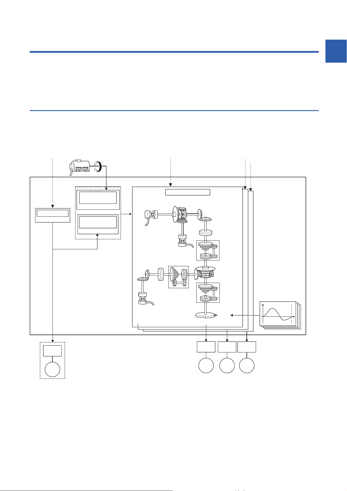
1 OUTLINE OF SYNCHRONOUS CONTROL
Positioning data
Positioning control
Positioning start Synchronous control start Synchronous control start
Synchronous encoder axis
Servo input axis
*1
Synchronous parameter
Synchronous control start
It is possible to control without amplifier
by setting the virtual servo amplifier.
Cam data
Output axis
Speed
change
gear
*2
Speed
change
gear
*2
Speed
change
gear
Auxiliary
shaft axis
Cam
Synchronous
encoder
Manual pulse generator/
Synchronous encoder input
Simple Motion module
Synchronous
encoder axis
parameter
Servo input axis
parameter
Auxiliary
shaft
clutch
Servo
amplifier
Servo
motor
Servo
amplifier
Servo
motor
Servo
motor
Servo
motor
Servo
amplifier
Servo
amplifier
Auxiliary
shaft
gear
Main shaft
(sub input axis)
Main shaft
(main input axis)
Composite
main shaft gear
Main shaft gear
Main shaft
clutch
Composite
auxiliary shaft
gear
*2
The outline, specifications and the operation method of synchronous control using the Simple Motion module are explained in
this chapter.
This chapter helps to understand what can be done using the positioning system and which procedure to use for a specific
purpose.
1.1 Outline of Synchronous Control
"Synchronous control" can be achieved using software instead of controlling mechanically with gear, shaft, speed change
gear or cam, etc.
"Synchronous control" synchronizes movement with the input axis (servo input axis or synchronous encoder axis), by setting
"the parameters for synchronous control" and starting synchronous control on each output axis.
1
*1 It is possible to drive the servo input axis except for the positioning control (home position return, manual control, speed-torque control,
synchronous control).
For details on the positioning control, the home position return, the manual control and the speed-torque control, refer to the following
manual of the Simple Motion module that is used.
User's Manual (Application)
*2 Speed change gear can be arranged on one of "Main shaft side", "Auxiliary shaft side" or "After composite auxiliary shaft gear".
1 OUTLINE OF SYNCHRONOUS CONTROL
1.1 Outline of Synchronous Control
15
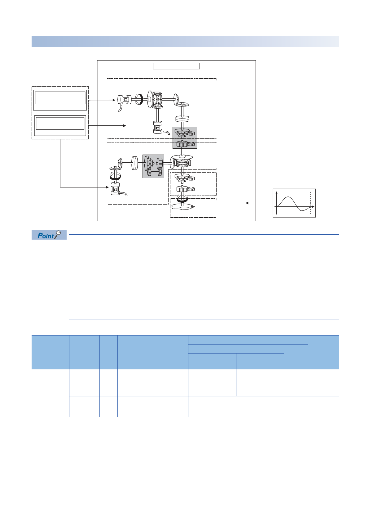
List of synchronous control module
Synchronous parameter
Synchronous encoder
axis parameter
Synchronous encoder axis
Servo input axis
parameter
Servo input axis
Input axis module
Main shaft module
Output axis
module
Cam data
Speed change
gear module
Auxiliary shaft module
Main shaft
(main input axis)
Auxiliary
shaft
clutch
Auxiliary
shaft
gear
Main shaft
(sub input axis)
Main shaft
gear
Main shaft
clutch
Composite
auxiliary
shaft gear
Composite main
shaft gear
Output axis
Speed
change
gear
Auxiliary shaft axis
Cam
The module is used in synchronous control as follows.
■Input axis
Classification Name Parts Function description Maximum number of usable Reference
Input axis
module
• Input axis module can be set to one of servo input axis or synchronous encoder axis.
• Speed change gear can be arranged on one of main shaft side, auxiliary shaft side or after composite
auxiliary shaft gear.
• Set the movement amount of input axis module as large as possible to prevent the speed fluctuation of
output axis module in the synchronous control. If the movement amount of input axis module is small, the
speed fluctuation of output axis module may occur depending on the setting for synchronous parameter.
• The following items can be monitored using the Simple Motion Module Setting Function; each synchronous
control monitor data and rotation direction of main shaft main input axis, main shaft sub input axis, auxiliary
shaft axis, and output axis (cam axis feed current value)
Number per module Number
per axis
Servo Input
Axis
Synchronous
Encoder Axis
Servo input
axis
Synchronous
encoder axis
• Used to drive the input axis with
• Used to drive the input axis with
the position of the servomotor
controlled by the Simple Motion
module.
input pulse from the
synchronous encoder.
2-axis
module
24816Page 24
4 Page 31
4-axis
module
8-axis
module
16-axis
module
16
1 OUTLINE OF SYNCHRONOUS CONTROL
1.1 Outline of Synchronous Control
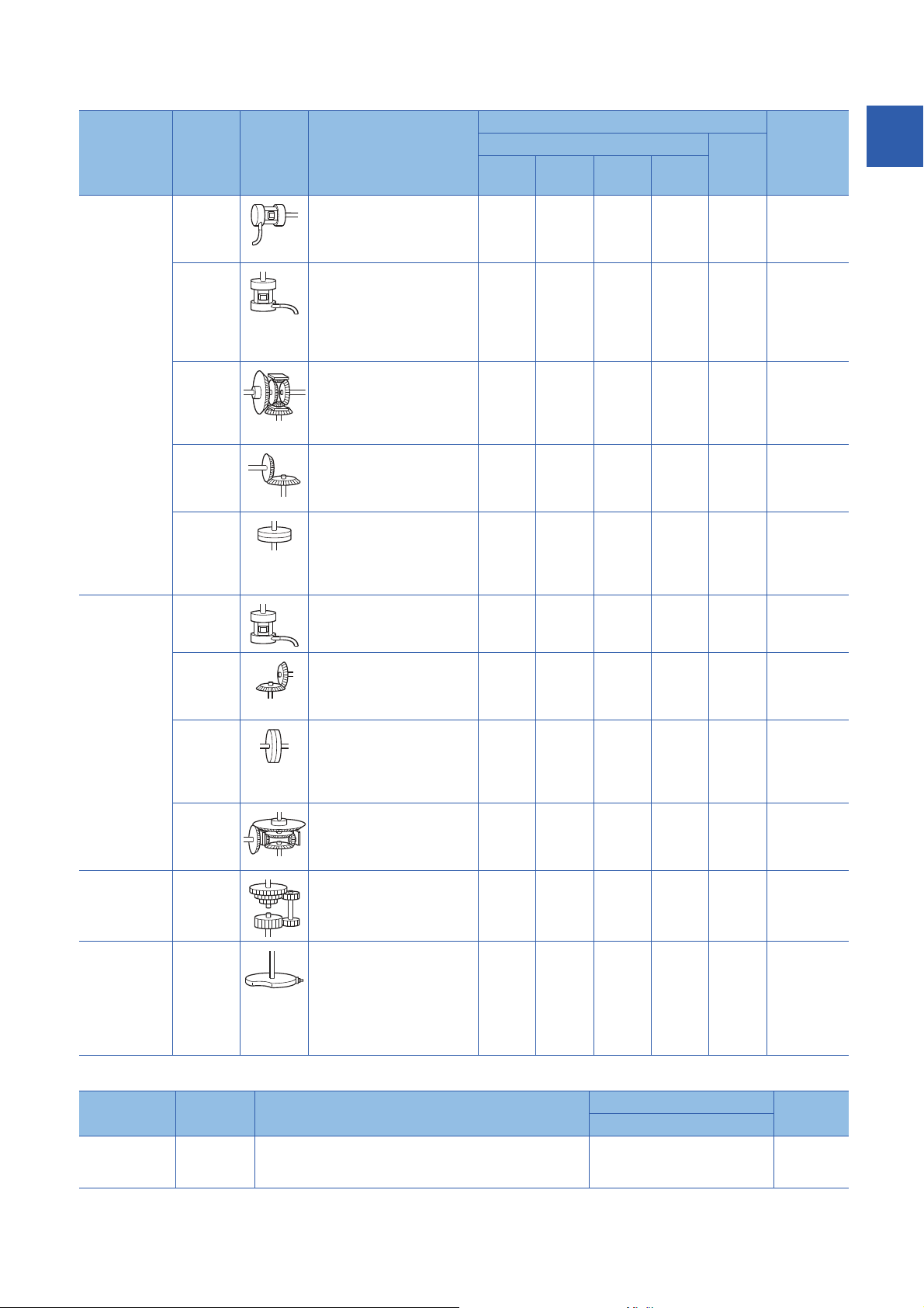
■Output axis
Classification Name Parts Function description Maximum number of usable Reference
Number per module Numbe
r per
axis
Main Shaft
Module
Main Shaft
Module
Main Shaft
Module
Main Shaft
Module
Main Shaft
Module
Page 77
Clutch
Auxiliary Shaft
Module
Main shaft
module
Auxiliary shaft
module
Main shaft
main input
axis
Main shaft
sub input
axis
Composite
main shaft
gear
Main shaft
gear
Main shaft
clutch
Auxiliary
shaft axis
• The input axis on the main
side of the main shaft module.
• The reference position on the
main shaft.
• The input axis on the sub side
of the main shaft module.
• It is used to input the
compensation amount for the
position of the main shaft main
input axis.
• The composite movement
amount of the main shaft main
input axis and the main shaft
sub input axis are transmitted
to the main shaft gear.
• The converting movement
amount after composite main
shaft gear is transmitted by
the setting gear ratio.
• The movement amount of the
main shaft is transmitted by
the clutch ON/OFF.
• The input axis of the auxiliary
shaft module.
2-axis
module
248161Page 61
248161Page 61
248161Page 61
248161Page 61
248161Page 61
248161Page 69
4-axis
module
8-axis
module
16-axis
module
1
Speed change
gear module
Output axis
module
Auxiliary
shaft gear
Auxiliary
shaft clutch
Composite
auxiliary
shaft gear
Speed
change
gear
Output axis • The cam conversion is
• The converting movement
amount of the auxiliary shaft is
transmitted by the setting gear
ratio.
• The movement amount of the
auxiliary shaft is transmitted
by the clutch ON/OFF.
• The composite movement
amount of the main shaft and
the auxiliary shaft are
transmitted.
• It is used to change the speed
by setting speed change ratio
during the operation.
processed based on the input
movement amount and the
setting cam data.
• The feed current value is
output as the command to the
servo amplifier.
248161Page 69
248161Page 69
248161
248161Page 88
248161Page 90
Auxiliary Shaft
Module
Auxiliary Shaft
Module
Page 77
Clutch
Page 69
Auxiliary Shaft
Module
Speed
Change Gear
Module
Output Axis
Module
■Cam data
Classification Name Function description Maximum number of usable Reference
Number per module
Cam data Cam data • It controls the operation pattern of the output axis (two-way
operation and feed operation), which is corresponding to the
input movement amount of the output axis module.
Up to 256 Page 48
CAM
FUNCTION
1 OUTLINE OF SYNCHRONOUS CONTROL
1.1 Outline of Synchronous Control
17

1.2 Performance Specifications
Performance specifications
Item Number of settable axes
2-axis module 4-axis module 8-axis module 16-axis module
Input axis Servo input axis 2 axes/module 4 axes/module 8 axes/module 16 axes/module
Synchronous encoder
axis
Composite main shaft gear 1/output axis
Main shaft main input axis 1 axis/output axis
Main shaft sub input axis 1 axis/output axis
Main shaft gear 1/output axis
Main shaft clutch 1/output axis
Auxiliary shaft 1 axis/output axis
Auxiliary shaft gear 1/output axis
Auxiliary shaft clutch 1/output axis
Composite auxiliary shaft gear 1/output axis
Speed change gear 1/output axis
Output axis (Cam axis) 2 axes/module 4 axes/module 8 axes/module 16 axes/module
Cam specifications
4 axes/module
Item Specification
Memory capacity Cam storage area 256k bytes
Cam open area 1024k bytes
Number of cam registration
Comment Up to 32 characters per cam data
Cam data Stroke ratio data format Cam resolution 256/512/1024/2048/4096/8192/16384/32768
*1 The maximum number of cam registration by the cam resolution is shown below. (In case it created by the same cam resolution.)
*1
Stroke ratio -214.7483648 to 214.7483647 [%]
Coordinate data format Coordinate number 2 to 16384
Coordinate data Input value: 0 to 2147483647
Up to 256
(Dependent on memory capacity, cam resolution and coordinate number)
Output value: -2147483648 to 2147483647
18
1 OUTLINE OF SYNCHRONOUS CONTROL
1.2 Performance Specifications

■Stroke ratio data format
Cam resolution Maximum number of cam registration
Cam storage area Cam open area
256 256 256
512 128 256
1024 64 256
2048 32 128
4096 16 64
8192 8 32
16384 4 16
32768 2 8
■Coordinate data format
Coordinate number Maximum number of cam registration
Cam storage area Cam open area
128 256 256
256 128 256
512 64 256
1024 32 128
2048 16 64
4096 8 32
8192 4 16
16384 2 8
1
Cam operation specifications
Item Specification
Operation method of cam data (1) Engineering tool
Write/read/verify to cam storage area
(2) Via buffer memory (Cam data operation function)
Write/read to cam storage area and cam open area
Cam auto-generation function Automatically generate the cam for rotary cutter.
Cam position calculation function Calculate the cam position by the program.
Used to calculate the cam position for the synchronous control initial position before starting synchronous
control.
Synchronous encoder axis specifications
Item Specification
Number of control axes 4
Synchronous encoder axis type Incremental synchronous encoder/
Control unit mm, inch, degree, pulse
Unit conversion Numerator -2147483648 to 2147483647
Denominator 1 to 2147483647
Length per cycle setting range 1 to 2147483647
Current value range Current value -2147483648 to 2147483647
Current value per cycle 0 to (Length per cycle - 1)
Control method Control instruction Current value change, Counter disable, Counter enable
Current value setting
address
Synchronous encoder via servo amplifier/
Synchronous encoder via CPU
(Possible to select the decimal places of position unit and speed unit)
[Synchronous encoder axis position unit]
[pulse]
[Synchronous encoder axis position unit]
[Synchronous encoder axis position unit]
[Synchronous encoder axis position unit]
Address setting range: -2147483648 to 2147483647
[Synchronous encoder axis position unit]
1 OUTLINE OF SYNCHRONOUS CONTROL
1.2 Performance Specifications
19
1.3 Operation Method of Synchronous Control
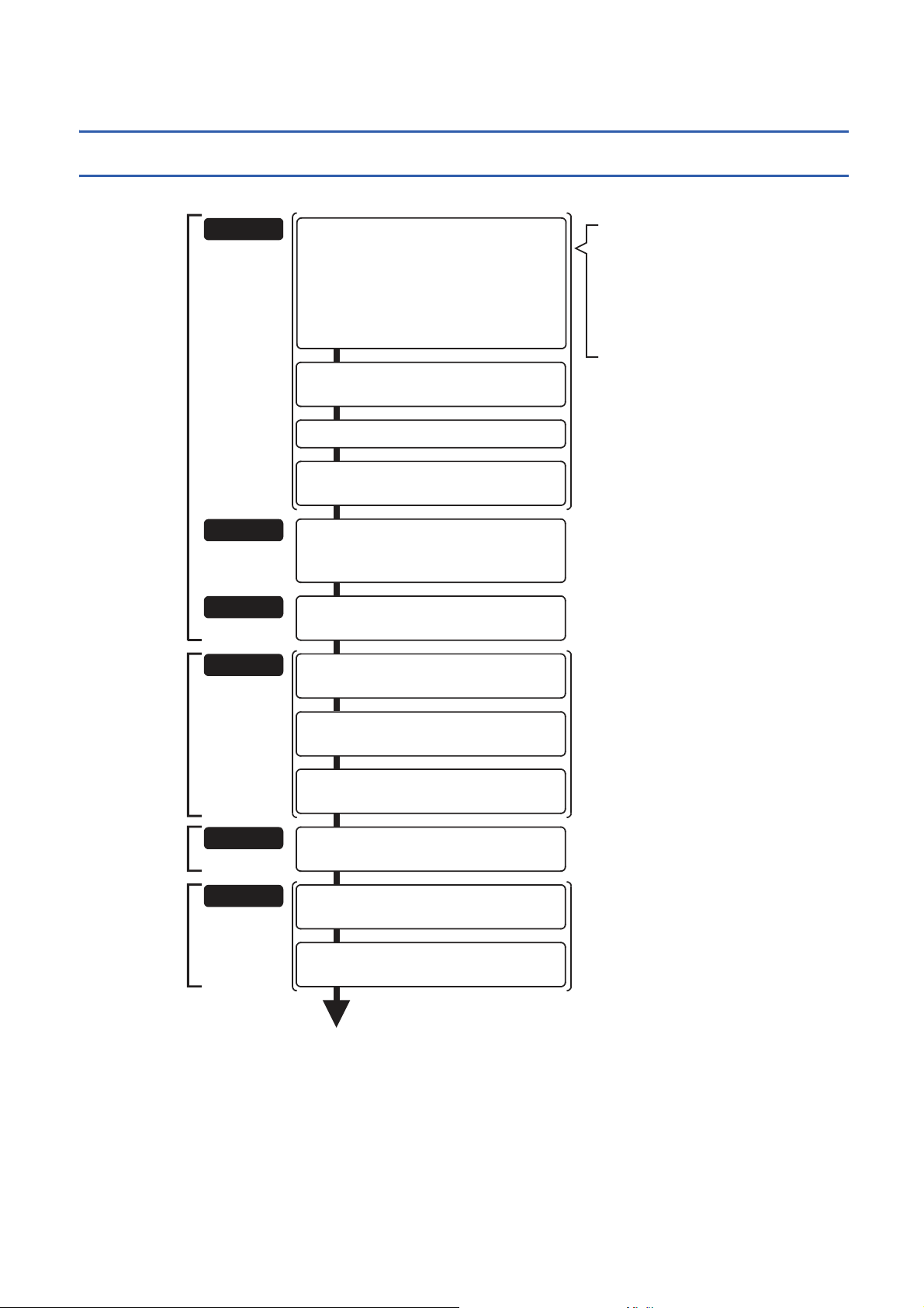
Set the following parameters.
• Common parameters ([Pr.24], [Pr.82], [Pr.89],
[Pr.96], [Pr.97], [Pr.150] to [Pr.153])
• Positioning parameters ([Pr.1] to [Pr.4],
[Pr.7] to [Pr.22], [Pr.25] to [Pr.42], [Pr.81],
[Pr.83], [Pr.84], [Pr.90], [Pr.95],
[Pr.116] to [Pr.119], [Pr.122], [Pr.123])
• Expansion parameters ([Pr.91] to [Pr.94])
STEP 1
Preparation
One of the following two methods can be used.
<Method 1>
Directly set (write) the parameters
in the Simple Motion module using
the engineering tool.
<Method 2>
Set (write) the parameters from
the CPU module to the Simple
Motion module using the program.
End of control
Turn ON the target axis bit in
"[Cd.380] Synchronous control start"
and start synchronous control
by the program in STEP 2.
*1
*2
*3
STEP 2
*4
STEP 3
Set the cam data.
Write the program, which is created
in STEP1 and STEP2, to the CPU module.
STEP 4
Start
synchronous
control
Turn ON the synchronous control start bit for
the axis that starts synchronous control.
Operate the input axis.
Operate the input axis by the program in STEP 2.
Turn OFF the target axis bit in
"[Cd.380] Synchronous control start"
to stop synchronous control
by the program in STEP 2.
STEP 5
Monitor the synchronous control operation status.
Execute the control change for the speed change
ratio, cam No., etc.
STEP 6
Complete
synchronous
control
Stop the input axis.
Verify the input axis is stopped and turn OFF the
synchronous control start bit for the axis that stops
synchronous control.
Stop the input axis by the program in STEP 2.
Monitor the
synchronous
control change
Monitor using the engineering tool.
Changing the control by the program in STEP 2.
Verify that it's during synchronous control.
Verify that it's during synchronous control in
"[Md.26] Axis operation status".
Set "input axis parameters" for synchronous control.
([Pr.300] to [Pr.304], [Pr.320] to [Pr.329])
Set "synchronous parameters" for synchronous
control. ([Pr.400] to [Pr.468])
Create a program that executes to start / change
control / stop synchronous control.
(Set "[Cd.380]Synchronous control start", start and
stop the input axis operation and change the
reduction ratio)
Synchronous control execution procedure
The synchronous control is executed using the following procedure.
*1 Page 24 INPUT AXIS MODULE
*2 Page 48 CAM FUNCTION
*3 Page 61 SYNCHRONOUS CONTROL, Page 110 Synchronous Control Initial Position Parameters
*4 Page 128 APPENDICES
20
1 OUTLINE OF SYNCHRONOUS CONTROL
1.3 Operation Method of Synchronous Control
Precautions
• Mechanical elements such as limit switches are considered as already installed.
Standby (0)
Analyzing (5)
Standby (0)
Synchronous control (15)
t
t
t
BUSY signal
[Cd.380] Synchronous control
start (Target axis bit)
[Md.26] Axis operation status
[Md.20] Feed current value
[Md.321] Synchronous encoder
axis current value per
cycle
[Md.407] Cam axis current
value per cycle
• Parameter settings for positioning control apply for all axes with the Simple Motion module.
• Be sure to execute the home position return when the home position return request flag is ON.
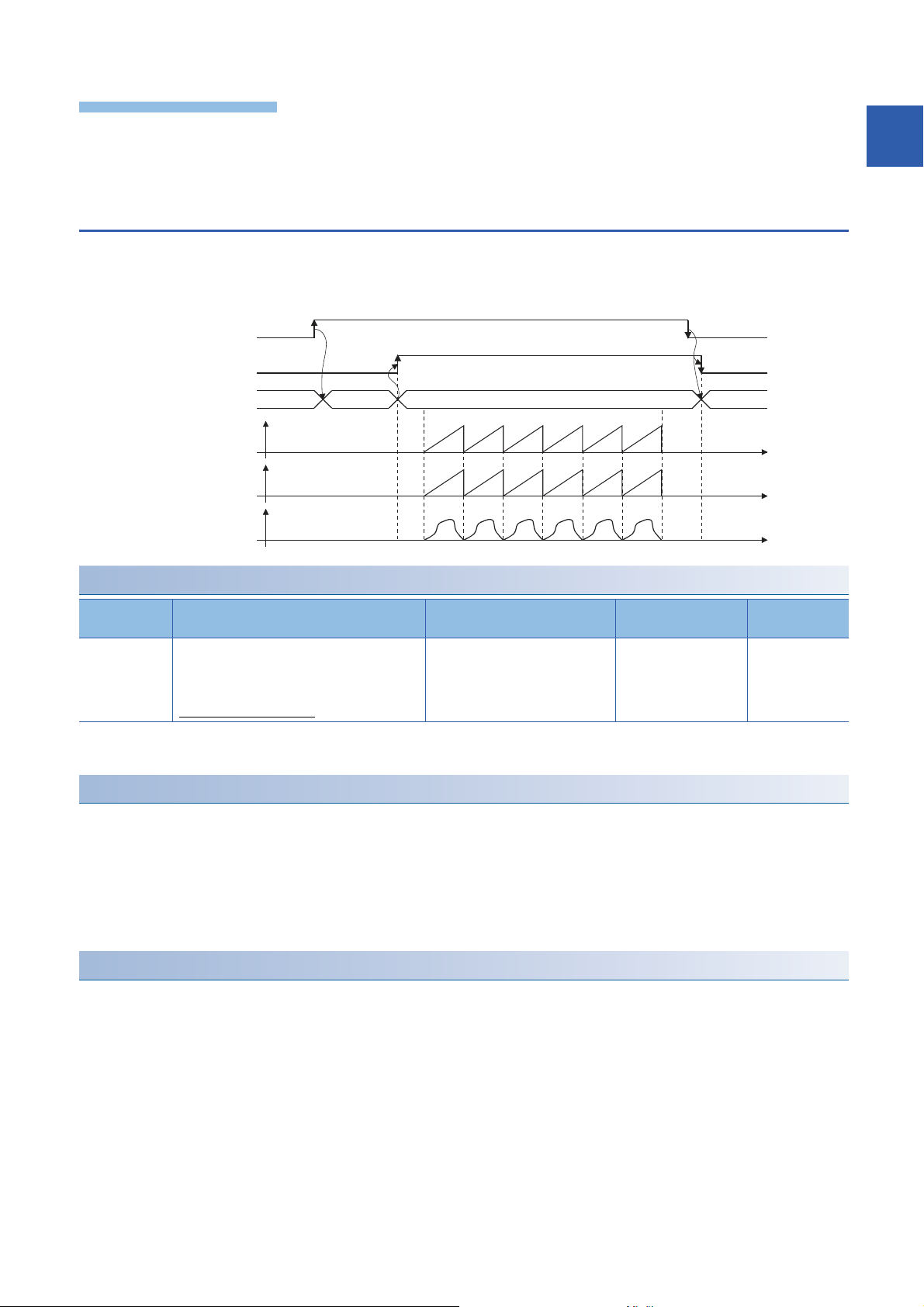
Starting/ending for synchronous control
Set the parameters for synchronous control for each output axis to start synchronous control.
The status changes to synchronous control after the parameters are analyzed at the start of synchronous control, and the
output axes synchronize with input axis operations.
1
Synchronous control system control data
Setting item Setting details Setting value Default value Buffer memory
[Cd.380]
Synchronous
control start
*1 The range from axis 1 to 2 is valid in the 2-axis module, from axis 1 to 4 is valid in the 4-axis module, and from axis 1 to 8 is valid in the
8-axis module.
Starting method for synchronous control
Synchronous control can be started by turning the target axis bit from OFF to ON in "[Cd.380] Synchronous control start" after
setting the parameters for synchronous control.
"5: Analyzing" is set in "[Md.26] Axis operation status" at the synchronous control start, and the parameters for synchronous
control are analyzed. The BUSY signal turns ON after completion of analysis, and "15: Synchronous control" is set in "[Md.26]
Axis operation status".
Start the input axis operation after confirming that "15: Synchronous control" is set in "[Md.26] Axis operation status".
Ending method for synchronous control
Synchronous control can be ended by turning the target axis bit from ON to OFF in "[Cd.380] Synchronous control start" after
the input axis operation is stopped.
The BUSY signal turns OFF at the synchronous control end, and "0: Standby" is set in "[Md.26] Axis operation status" at the
output axis stop.
Synchronous control can also be ended by turning the target axis bit from ON to OFF in "[Cd.380] Synchronous control start"
during the input axis operation. However, it is recommended to end after stopping the input axis operation since the output
axis stops immediately.
Refer to the following for the stop operation of output axis at the synchronous control end.
Page 23 Stop operation of output axis
• Synchronous control begins if the target axis bit
is turned ON.
• Synchronous control ends if the bit is turned
OFF during synchronous control.
Fetch cycle: Operation cycle
■Set the target axis in 16 bits.
(bit0: axis 1 to bit15: axis 16
OFF : Synchronous control end
ON : Synchronous control start
address
*1
)
1 OUTLINE OF SYNCHRONOUS CONTROL
1.3 Operation Method of Synchronous Control
0 36320
21

Starting history
The starting history is updated when starting synchronous control. "9020: Synchronous control operation" is stored in "[Md.4]
Start No.".
Status when starting synchronous control
The following bits in "[Md.31] Status" are turned OFF when starting synchronous control in the same way as for the positioning
control start.
Bit Details
b0 In speed control flag
b1 Speed-position switching latch flag
b2 Command in-position flag
b4 Home position return complete flag
b5 Position-speed switching latch flag
b10 Speed change 0 flag
• If bit for multiple axes are turned ON simultaneously in "[Cd.380] Synchronous control start", control is not
started simultaneously since the analysis is processed for each axis in numerical order. When the multiple
axes must be started simultaneously, start the input axis operation after confirming that all axes are
configured for the synchronous control.
• If the input axis operates during the analysis at the synchronous control start, the movement amount of the
input axis is reflected immediately after the synchronous control start. The output axis might suddenly
accelerate depending on the movement amount of the input axis. Start the input axis operation after
confirming that are configured for synchronous control.
• The analysis process for synchronous control start might take time depending on the parameter setting for
synchronous control. (When "0: Cam axis current value per cycle restoration" is set in "[Pr.462] Cam axis
position restoration object" and the cam (cam resolution: 32768) is searched: About 26 ms, When "0: Cam
axis current value per cycle restoration" is set in "[Pr.462] Cam axis position restoration object" and the cam
(cam resolution: 256) is searched: About 0.4 ms) Set "1: Cam reference position restoration" or "2: Cam
axis feed current value restoration" in "[Pr.462] Cam axis position restoration object" to start synchronous
control at high speed.
• When the synchronous control parameter is set to the value outside the setting range, the synchronous
control does not start, and the input axis error No. is stored in the monitor data.
22
1 OUTLINE OF SYNCHRONOUS CONTROL
1.3 Operation Method of Synchronous Control
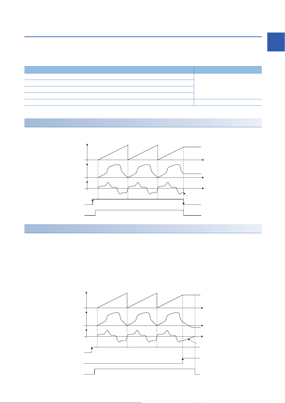
Stop operation of output axis
t
BUSY signal
[Md.22] Feedrate
t
t
Immediate stop
[Md.407] Cam axis current value
per cycle
[Md.20] Feed current value
(Cam operation)
[Cd.380] Synchronous control start
(Target axis bit)
Slope of deceleration
=
"[Pr.8] Speed limit value"
/
Deceleration time
(Sudden stop deceleration time)
t
Axis stop signal
[Md.22] Feedrate
t
t
BUSY signal
Deceleration stop
[Md.407] Cam axis current value
per cycle
[Cd.380] Synchronous control start
(Target axis bit)
[Md.20] Feed current value
(Cam operation)
If the following causes occur in stopping the output axis during synchronous control, synchronous control is completed after
stops processing for the output axis (BUSY signal is OFF, axis operation status is standby).
Synchronous alignment must be executed for the output axis to restart the synchronous control. (Page 90 Output Axis
Module)
Stop cause Stop process
The target axis bit of "[Cd.380] Synchronous control start" is turned from ON to OFF. Immediate stop
Software stroke limit error occurrence
Emergency stop
Forced stop
Stop group1 to 3*1 (Stop with hardware stroke limit or stop command) Deceleration stop
*1 Refer to "User's Manual (Application)" of the Simple Motion module that is used.
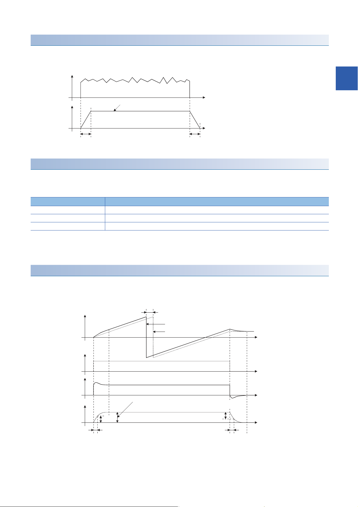
Immediate stop
The operation stops without decelerate. The Simple Motion module immediately stops the command, but the operation will
coast for the droop pulses accumulated in the deviation counter of the servo amplifier.
1
Deceleration stop
The output axis stops with deceleration according to the setting in "[Pr.37] Stop group 1 sudden stop selection" to "[Pr.39] Stop
group 3 sudden stop selection". The deceleration time is set in "[Pr.446] Synchronous control deceleration time" for
deceleration stop, and in "[Pr.36] Sudden stop deceleration time" for sudden stop. The slope of deceleration is as follows.
The cam axis current value per cycle is not updated, and only the feed current value is updated, since the deceleration stop
begins. Therefore, the path of the feed current value is drawn regardless the cam operation with deceleration stop.
The input axis must be stopped when the output axis is stop synchronizing with the input axis.
1 OUTLINE OF SYNCHRONOUS CONTROL
1.3 Operation Method of Synchronous Control
23
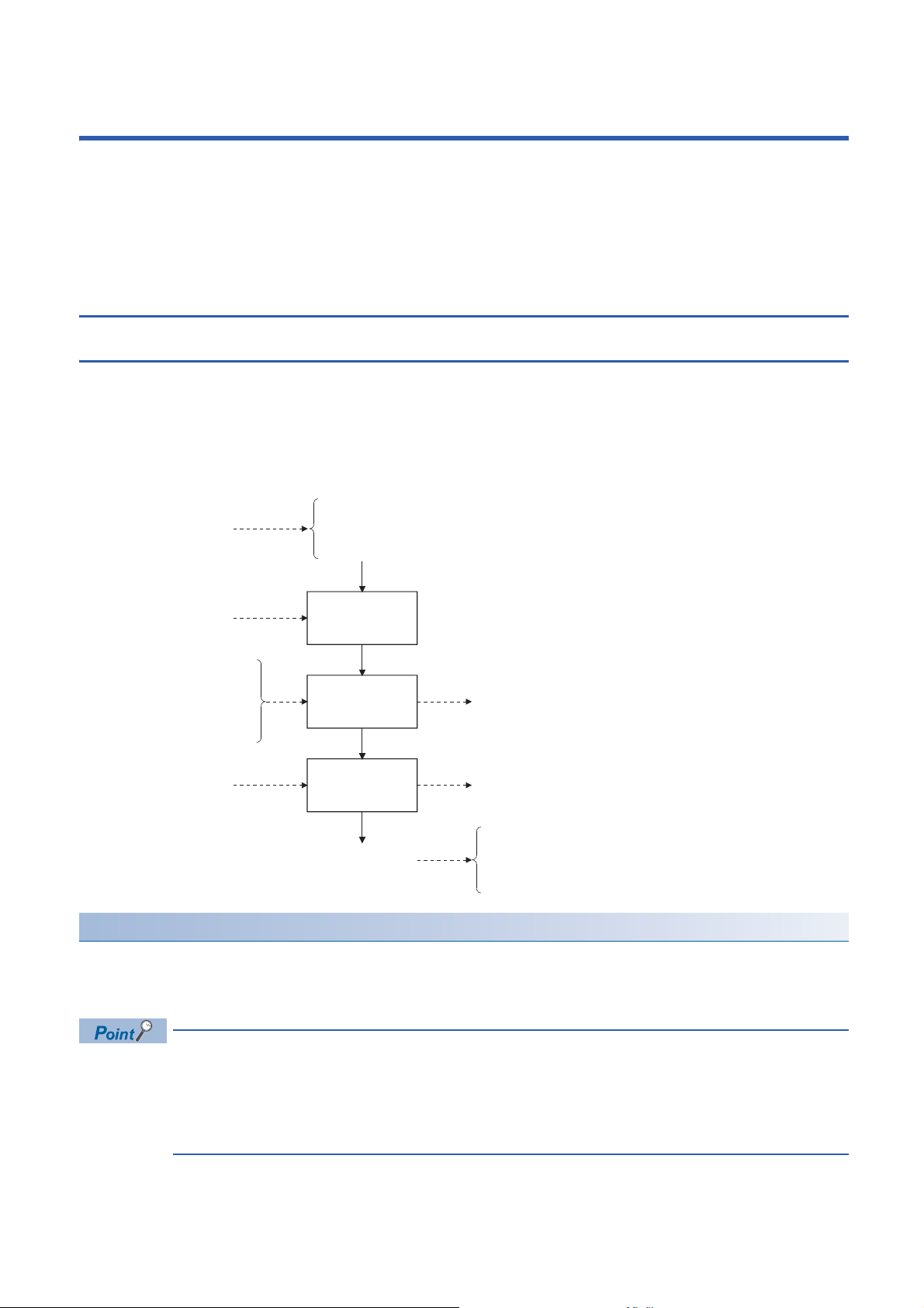
2 INPUT AXIS MODULE
Input smoothing
processing
Phase
compensation
processing
Rotation
direction
restriction
Feed current value
Real current value
Servo command value
Feedback value
Servo motor position
Current value of
servo input axis
[Pr.300] Servo input axis
type
[Pr.301] Servo input axis
smoothing time
constant
[Pr.302] Servo input axis phase
compensation advance
time
[Md.303] Servo input axis
rotation direction
restriction amount
[Md.300] Servo input axis
current value
[Md.301] Servo input axis speed
[Md.302] Servo input axis phase
compensation amount
[Pr.303] Servo input axis phase
compensation time
constant
[Pr.304] Servo input axis
rotation direction
restriction
The settings for the parameter and monitor data for the input axis module that used with synchronous control are explained in
this chapter.
Refer to the following manual of the Simple Motion module that is used for details on the connection and control for the servo
amplifier and the synchronous encoder that used for input axis module.
User's Manual (Application)
2.1 Servo Input Axis
Overview of servo input axis
The servo input axis is used to drive the input axis based on the position of the servomotor that is being controlled by the
Simple Motion module.
The status of a servo input axis can also be monitored even before the synchronous control start since the setting of a servo
input axis is valid after the system's power supply ON.
The following shows the relationship between the position of the servomotor and the servo input axis.
Control method for servo input axis
All controls (including synchronous control) can be executed for a servo input axis.
Refer to the following manual of the Simple Motion module that is used for the controls other than the synchronous control.
User's Manual (Application)
24
2 INPUT AXIS MODULE
2.1 Servo Input Axis
If the virtual servo amplifier function is set in the servo input axis, synchronous control can be executed by the
input value as virtual.
Refer to the following manual of the Simple Motion module that is used for details on virtual servo amplifier
function.
User's Manual (Application)

If "1: Feed current value" or "2: Real current value" is set in "[Pr.300] Servo input axis type", set "1: Update
feed current value" in "[Pr.21] Feed current value during speed control" to start the speed position change
control. If "0: Do not update feed current value" or "2: Clear feed current value to zero" is set in [Pr.21], the
error "Speed-position switching control start in servo input axis not possible" (error code: 1BA7H) will occur
and the control will not start.
Units for the servo input axis
The position units and speed units for the servo input axis are shown below for the setting "[Pr.300] Servo input axis type" and
"[Pr.1] Unit setting".
■Servo input axis position units
2
Setting value of "[Pr.300]
Servo input axis type"
1: Feed current value
2: Real current value
3: Servo command value
4: Feedback value
Setting value of "[Pr.1] Unit
setting"
0: mm 10-4mm
1: inch 10
2: degree 10-5degree -21474.83648 to 21474.83647 [degree]
3: pulse pulse -2147483648 to 2147483647 [pulse]
pulse -2147483648 to 2147483647 [pulse]
Servo input axis position
unit
-1
(10
m)
-5
inch -21474.83648 to 21474.83647 [inch]
Range
-214748.3648 to 214748.3647 [mm]
(-214748364.8 to 214748364.7 [m])
■Servo input axis speed units
Setting value of "[Pr.300]
Servo input axis type"
1: Feed current value
2: Real current value
3: Servo command value
4: Feedback value
*1 When "[Pr.83] Speed control 10 x multiplier setting for degree axis" is valid, this will be the speed unit " 10-2degree/min"
(Range: - 21474836.48 to 21474836.47 [degree/min]).
• When "1: Feed current value" or "3: Servo command value" is set in "[Pr.300] Servo input axis type", and the
servo input axis becomes servo OFF by the servo error or forced stop, the amount of value change may be
large. This can be prevented by setting "2: Real current value" or "4: Feedback value" in "[Pr.300] Servo
input axis type".
• When a home position return for the axis where "1: Feed current value" or "2: Real current value" is set in
"[Pr.300] Servo input axis type" is performed, if the servo input axis operation during home position return is
used as the input value, the input is stopped in the midway of home position return. When the servo input
axis operation during home position return is used as the input value, set "3: Servo command value" or "4:
Feedback value" in "[Pr.300] Servo input axis type".
Setting value of "[Pr.1] Unit
setting"
0: mm 10-2mm/min -21474836.48 to 21474836.47 [mm/min]
1: inch 10-3inch/min -2147483.648 to 2147483.647 [inch/min]
2: degree 10-3degree/min
3: pulse pulse/s -2147483648 to 2147483647 [pulse/s]
pulse/s -2147483648 to 2147483647 [pulse/s]
Servo input axis speed unit Range
*1
-2147483.648 to 2147483.647 [degree/min]
*1
2 INPUT AXIS MODULE
2.1 Servo Input Axis
25

Servo input axis parameters
Simple Motion module
Unit → Pulse conversion
(Backlash compensation)
1: Feed current value 3: Servo command value
2: Real current value
Pulse → Unit conversion
4: Feedback value
Servo
amplifier
n: Axis No. - 1
Setting item Setting details Setting value Default value Buffer memory
address
[Pr.300]
Servo input axis type
[Pr.301]
Servo input axis smoothing time
constant
[Pr.302]
Servo input axis phase compensation
advance time
[Pr.303]
Servo input axis phase compensation
time constant
[Pr.304]
Servo input axis rotation direction
restriction
• Set the current value type to be
generated of the input value for the
servo input axis.
Fetch cycle: At power supply ON
• Set to smooth the input value.
Fetch cycle: At power supply ON
• Set the time to advance or delay
the phase.
Fetch cycle: Operation cycle
• Set the time constant to affect the
phase compensation.
Fetch cycle: At power supply ON
• Set this parameter to restrict the
input movement amount to one
direction.
Fetch cycle: At power supply ON
■Set in decimal.
0: Invalid
1: Feed current value
2: Real current value
3: Servo command value
4: Feedback value
■Set in decimal.
0 to 5000 [ms]
■Set in decimal.
-2147483648 to 2147483647 [s]
■Set in decimal.
0 to 65535 [ms]
■Set in decimal.
0: Without rotation direction
restriction
1: Enable only for current value
increase direction
2: Enable only for current value
decrease direction
*1
0 32800+10n
0 32801+10n
0 32802+10n
32803+10n
10 32804+10n
0 32805+10n
*1 Set the value as follows in a program.
0 to 32767: Set as a decimal.
32768 to 65535: Convert into a hexadecimal and set.
[Pr.300] Servo input axis type
Set the current value type to be generated of the input value for the servo input axis.
Setting value Details
0: Invalid Servo input axis is invalid.
1: Feed current value Generate the input value based on "[Md.20] Feed current value".
2: Real current value Generate the input value based on the real current value, which is converted into units of the encoder feedback pulses
3: Servo command value Generate the input value based on the command pulse for the servo amplifier (a value that the feed current value is
4: Feedback value Generate the input value based on the encoder feedback pulse from the servo amplifier.
from the servo amplifier.
converted into encoder pulse units).
26
2 INPUT AXIS MODULE
2.1 Servo Input Axis
[Pr.301] Servo input axis smoothing time constant
[Pr.301] Servo input axis smoothing
time constant
[Pr.301] Servo input axis smoothing
time constant
t
t
Input value speed
before smoothing
Input value speed
after smoothing
Averaging by
smoothing time constant
t
Servo input axis
current value
t
t
t
63%
63%
Speed before phase
compensation
Speed after phase
compensation
Current value after
phase compensation
Current value before phase compensation
Speed before
phase
compensation
[Pr.302] Servo input axis phase
compensation advance time
[Md.302] Servo input
axis phase
compensation
amount
×
[Md.302] Servo input axis
phase compensation
amount
[Pr.303] Servo input axis phase
compensation time constant
[Pr.303] Servo input axis phase
compensation time constant
Set the averaging time to execute a smoothing process for the input movement amount from the servo input axis.
The smoothing process can moderate speed fluctuation, when the "Real current value" or "Feedback value" is used as input
values. The input response is delayed depending on the time corresponding to the setting by smoothing process setting.
[Pr.302] Servo input axis phase compensation advance time
Set the time to advance or delay the phase (input response) of the servo input axis.
Refer to the following for the delay time inherent to the system using the servo input axis.
Page 104 Phase Compensation Function
Setting value Details
1 to 2147483647 [s] Advance the phase (input response) according to the setting time.
0 [s] Do not execute phase compensation.
-2147483648 to -1 [s] Delay the phase (input response) according to the setting time.
2
If the setting time is too long, the system experiences overshoot or undershoot at acceleration/deceleration of the input speed.
In this case, set longer time to affect the phase compensation amount in "[Pr.303] Servo input axis phase compensation time
constant".
[Pr.303] Servo input axis phase compensation time constant
Set the time constant to affect the phase compensation amount for the first order delay.
63 [%] of the phase compensation amount are reflected in the time constant setting.
2 INPUT AXIS MODULE
2.1 Servo Input Axis
27
[Pr.304] Servo input axis rotation direction restriction
t
Speed before rotation
direction restriction
t
t
The input movement amount is accumulated as a rotation
direction restricted amount, and will be reflected when
the input movement amount in the enabled direction.
For "1: Enable only for current value increase direction" is set in "[Pr.304] Servo input axis rotation direction restriction".
[Md.301] Servo input axis speed
(Speed after rotation
direction restriction)
[Md.303] Servo input axis
rotation direction
restriction amount
Set this parameter to restrict the input movement amount for the servo input axis to one direction.
This helps to avoid reverse operation caused by machine vibration, etc. when "Real current value" or "Feedback value" is
used as input values.
Setting value Details
0: Without rotation direction restriction Rotation direction restriction is not executed.
1: Enable only for current value increase direction Enable only the input movement amount in the increasing direction of the
2: Enable only for current value decrease direction Enable only the input movement amount in the decreasing direction of the
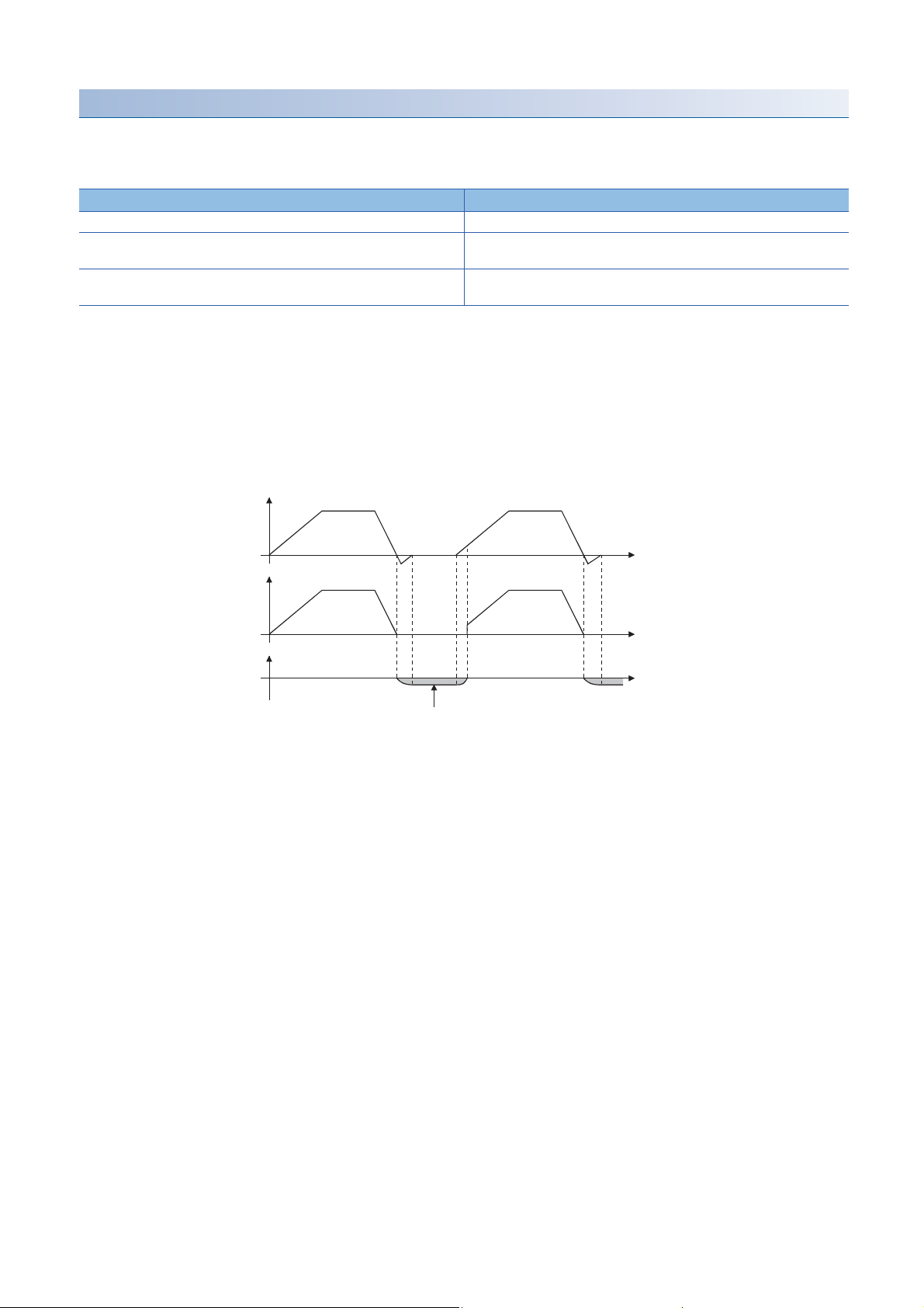
The input movement amount in the reverse direction of the enabled direction accumulates as a rotation direction restricted
amount, and will be reflected when the input movement amount moves in the enabled direction again. Therefore, the current
value of servo input does not deviate when the reverse operation is repeated.
The rotation direction restricted amount is set to 0 when the following operations are executed for the servo input axis.
• A servo amplifier is connected
• The home position return is executed
• The current value is changed
servo input axis current value.
servo input axis current value.
2 INPUT AXIS MODULE
28
2.1 Servo Input Axis
 Loading...