

Mitsubishi QJ71NT11B, QJ71LP21S-25, QJ71LP21-25, QJ71LP21G, QJ71LP21GE Reference Manual
...
Q Corresponding MELSECNET/H
Network System
Reference Manual (PLC to PLC network)
-QJ71LP21
-QJ71LP21-25
-QJ71LP21S-25
-QJ71LP21G
-QJ71LP21GE
-QJ71BR11
-QJ71NT11B

• SAFETY PRECAUTIONS •
(Read these precautions before using this product.)
Before using this product, please read this manual and the relevant manuals carefully and pay full
attention to safety to handle the product correctly.
The instructions given in this manual are concerned with this product. For the safety instructions of the
programmable controller system, please read the CPU module user's manual.
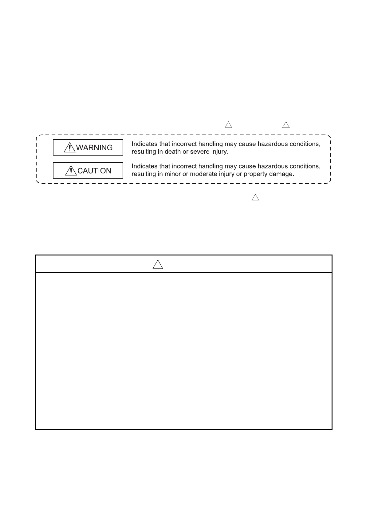
In this manual, the safety precautions are classified into to levels: " WARNING" and " CAUTION".
! !
Under some circumstances, failure to observe the precautions given under " CAUTION" may lead to
serious consequences.
Observe the precautions of both levels because they are important for personal and system safety.
Make sure that the end users read this manual and then keep the manual in a safe place for future
reference.
!
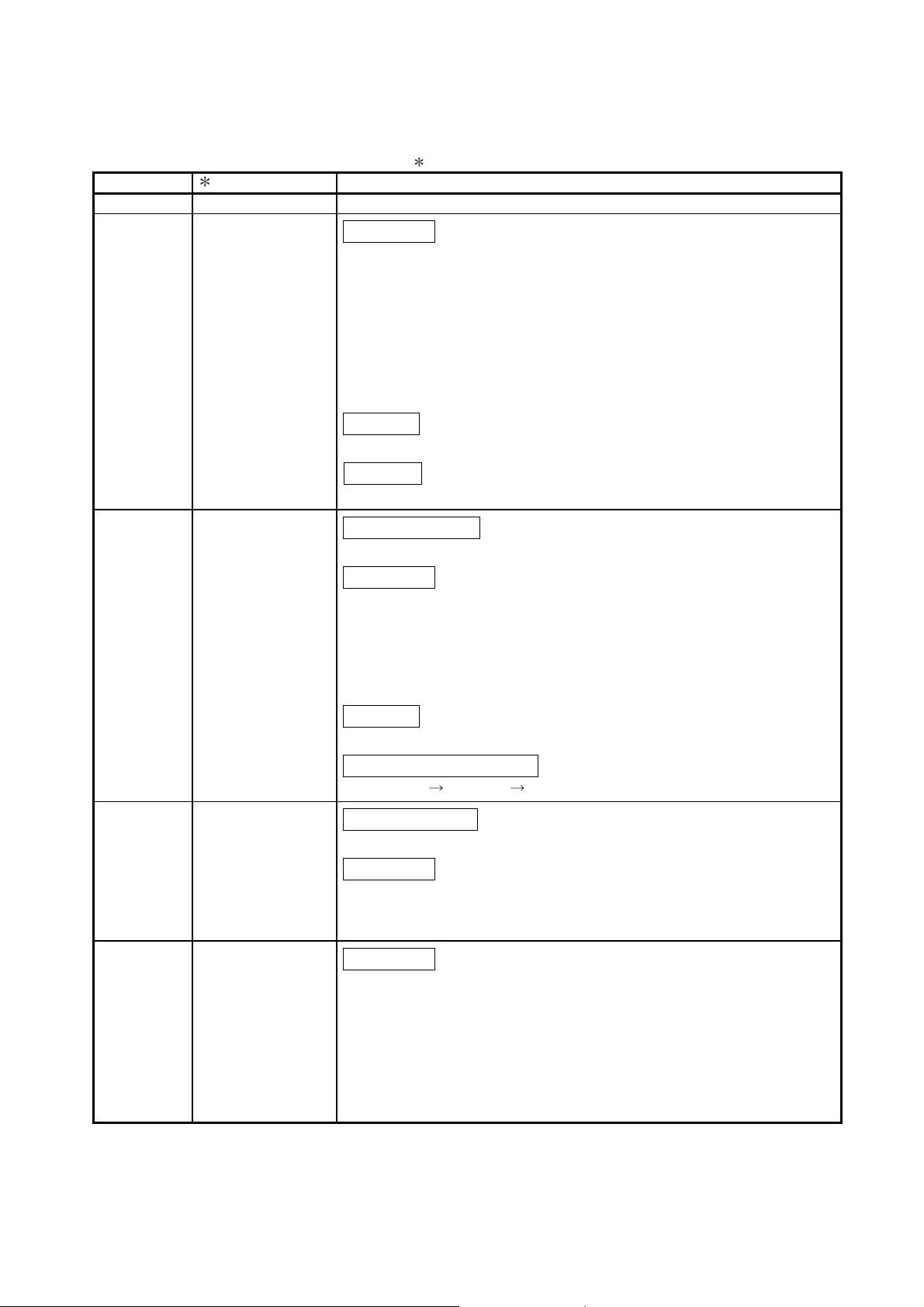
[Design Precautions]
!
WARNING
• For operating status of each communication failure, refer to this manual. Incorrect output or
malfunction due to a communication failure may result in an accident.
• If a coaxial cable is disconnected, this may destabilize the line, and a network communication
error may occur in multiple stations. Provide an interlock circuit in the sequence program so that
the system will operate safely even if the above error occurs. Failure to do so may result in an
accident due to incorrect output or malfunction.
• When changing data of the running programmable controller from a peripheral connected to the
CPU module or from a personal computer connected to an intelligent function module or special
function module, configure an interlock circuit in the sequence program to ensure that the entire
system will always operate safely.
For program modification and operating status change, read relevant manuals carefully and
ensure the safety before operation.
Especially, in the case of a control from an external device to a remote programmable controller,
immediate action cannot be taken for a problem on the programmable controller due to a
communication failure.
To prevent this, configure an interlock circuit in the sequence program, and determine corrective
actions to be taken between the external device and CPU module in case of a communication
failure.
A - 1 A - 1

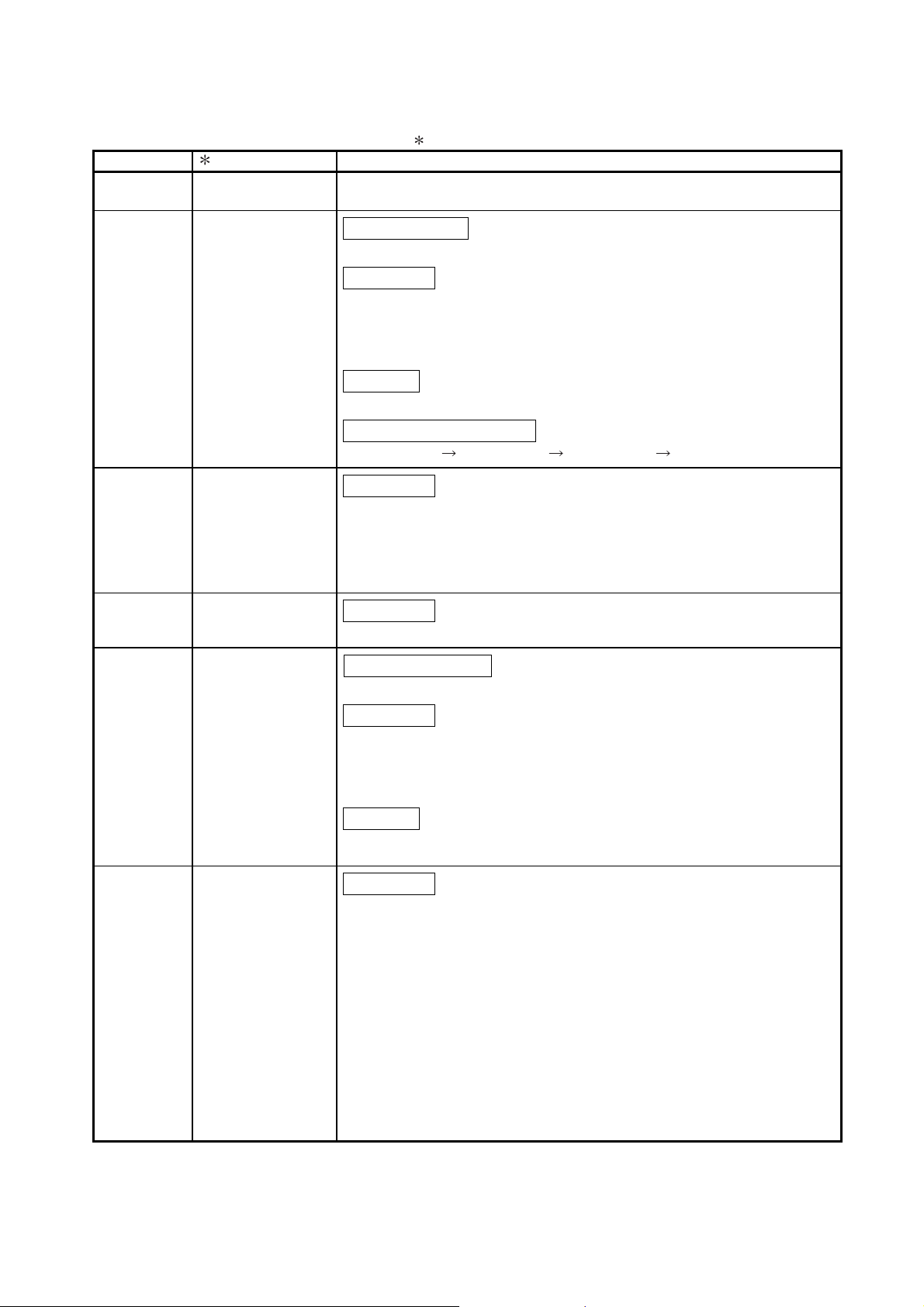
[Design Precautions]
!
CAUTION
• Do not install the control lines or communication cables together with the main circuit lines or
power cables.
Keep a distance of 100mm or more between them.
Failure to do so may result in malfunction due to noise.
[Installation Precautions]
!
CAUTION
• Use the programmable controller in the operating an environment that meets the general
specifications given in the user's manual for the CPU module used.
Failure to do so may result in electric shock, fire, malfunction, or damage to or deterioration of
the product.
• To mount the module, while pressing the module mounting lever located in the lower part of
module, fully insert the module fixing projection(s) into the hole(s) in the base unit press the
module until it snaps into place.
Incorrect mounting may cause malfunction, failure or drop of the module.
When using the programmable controller in an environment of frequent vibrations, fix the
module a screw.
Tighten the screw within the specified torque range.
Undertightening can cause drop of the screw, short circuit or malfunction.
Overtightening can damage the screw and/or module, resulting in drop, short circuit, or
malfunction.
• Shut off the external power supply for the system in all phases before mounting or removing the
module. Failure to do so may result in damage to the product.
• Do not directly touch any conductive part of the module.
Doing so can cause malfunction or failure of the module.
A - 2 A - 2

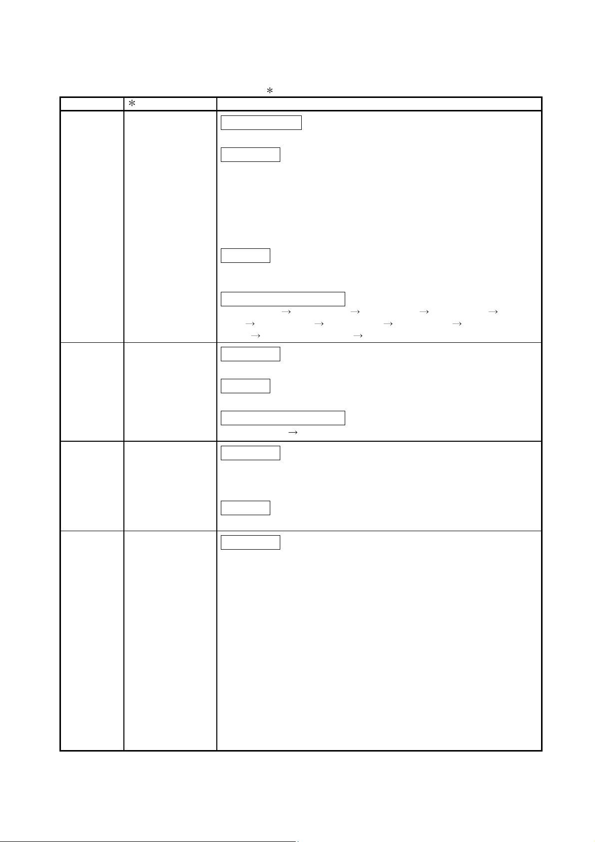
[Wiring Precautions]
!
WARNING
• Shut off the external power supply (all phases) used in the system before installation and wiring.
Failure to do so may result in electric shock or damage to the product.
!
CAUTION
• Individually ground the FG terminal of the programmable controller with a ground resistance of
100 or less.
Failure to do so may result in electric shock malfunction.
• Check the rated voltage and terminal layout before wiring to the terminal block for the external
power supply, and connect the cable correctly.
Connecting a cable to power supply with a different voltage rating or incorrect wiring may cause
a fire or failure.
• Tighten the terminal screw within the specified torque range.
Undertightening can cause drop of the screw, short circuit or malfunction.
Overtightening can damage the screw and/or module, resulting in drop, short circuit, or
malfunction.
• Properly solder the parts of a soldering-type coaxial cable connector. Incomplete soldering may
result in malfunction.
• Crimp the parts of a crimping-type coaxial cable connector with proper force at a proper position.
Failure to do so may cause drop of the cable or malfunction.
• Prevent foreign matter such as dust or wire chips from entering the module.
Such foreign matter can cause a fire, failure, or malfunction.
• A protective film is attached to the top of the module to prevent foreign matter, such as wire
chips, from entering the module during wiring.
Do not remove this film during wiring.
Remove it for heat dissipation before system operation.
• Place the cables in a duct or clamp them.
Failure to do so may cause damage of the module or the cables due to accidental pull or
unintentional shifting of the cables, or malfunctions due to poor contact of the cable.
• Do not install the control lines or communication cables together with the main circuit lines or
power cables.
Keep a distance of 100mm or more between them.
Failure to do so may result in malfunction due to noise.
• When disconnecting the communication and power cables from the module, do not pull the
cable by the cable part. Loosen the screws of connector before disconnecting the cable. When
disconnecting a cable connected to a terminal block, loosen the screws on the terminal block
first before removing the cable.
Failure to do so may result in damage to the module or cable or malfunction due to poor contact.
A - 3 A - 3

[Setup and Maintenance Precautions]
!
CAUTION
• Before performing online operations (especially, program modification, forced output, and
operation status change) for the running CPU module in other station from GX Developer via
MELSECNET/H, read relevant manuals carefully and ensure the safety.
• Do not disassemble or modify the module. Doing so may cause failure, malfunction, injury, or a
fire.
• Use any radio communication device such as a cellular phone or a PHS (Personal Handy-phone
System) more than 25cm (9.85 inches) away in all directions from the programmable controller.
Failure to do so may cause malfunction.
• Shut off the external power supply for the system in all phases before mounting or removing the
module. Failure to do so may cause the module to fail or malfunction.
• Do not touch any terminals while power is on. Doing so will cause electric shock.
• Shut external power supply for the system before cleaning the module or retightening the
terminal screws or module fixing screws.
Failure to do so may cause the module to fail or malfunction.
Undertightening can cause drop of the screw, short circuit or malfunction.
Overtightening can damage the screw and/or module, resulting in drop, short circuit, or
malfunction.
• After the firs use of the product, do not mount/remove the module to/from the base unit more
than 50 times (IEC 61131-2 compliant) respectively.
Exceeding the limit of 50 times may cause malfunction.
• Before handling the module, touch a grounded metal object to discharge the static electricity
from the human body.
Failure to do so may cause the module to fail or malfunction.
[Disposal Precautions]
!
CAUTION
• When disposing of this product, treat it as industrial waste.
A - 4 A - 4

• CONDITIONS OF USE FOR THE PRODUCT •
(1) Mitsubishi programmable controller ("the PRODUCT") shall be used in conditions;
i) where any problem, fault or failure occurring in the PRODUCT, if any, shall not lead to any major
or serious accident; and
ii) where the backup and fail-safe function are systematically or automatically provided outside of
the PRODUCT for the case of any problem, fault or failure occurring in the PRODUCT.
(2) The PRODUCT has been designed and manufactured for the purpose of being used in general
industries.
MITSUBISHI SHALL HAVE NO RESPONSIBILITY OR LIABILITY (INCLUDING, BUT NOT
LIMITED TO ANY AND ALL RESPONSIBILITY OR LIABILITY BASED ON CONTRACT,
WARRANTY, TORT, PRODUCT LIABILITY) FOR ANY INJURY OR DEATH TO PERSONS OR
LOSS OR DAMAGE TO PROPERTY CAUSED BY the PRODUCT THAT ARE OPERATED OR
USED IN APPLICATION NOT INTENDED OR EXCLUDED BY INSTRUCTIONS, PRECAUTIONS,
OR WARNING CONTAINED IN MITSUBISHI'S USER, INSTRUCTION AND/OR SAFETY
MANUALS, TECHNICAL BULLETINS AND GUIDELINES FOR the PRODUCT.
("Prohibited Application")
Prohibited Applications include, but not limited to, the use of the PRODUCT in;
Nuclear Power Plants and any other power plants operated by Power companies, and/or any other
cases in which the public could be affected if any problem or fault occurs in the PRODUCT.
Railway companies or Public service purposes, and/or any other cases in which establishment of
a special quality assurance system is required by the Purchaser or End User.
Aircraft or Aerospace, Medical applications, Train equipment, transport equipment such as
Elevator and Escalator, Incineration and Fuel devices, Vehicles, Manned transportation,
Equipment for Recreation and Amusement, and Safety devices, handling of Nuclear or
Hazardous Materials or Chemicals, Mining and Drilling, and/or other applications where there is a
significant risk of injury to the public or property.
Notwithstanding the above, restrictions Mitsubishi may in its sole discretion, authorize use of the
PRODUCT in one or more of the Prohibited Applications, provided that the usage of the PRODUCT
is limited only for the specific applications agreed to by Mitsubishi and provided further that no
special quality assurance or fail-safe, redundant or other safety features which exceed the general
specifications of the PRODUCTs are required. For details, please contact the Mitsubishi
representative in your region.
A - 5 A - 5
REVISIONS
The manual number is given on the bottom left of the back cover.
Print Date Manual Number Revision
Dec., 1999 SH(NA)-080049-A First printing
Oct., 2000 SH(NA)-080049-B
Correction
Safety Precautions, Contents, About Manuals, About the Generic
Terms and Abbreviations, Chapter 1, Section 1.1, 1.2, Chapter 2,
Section 2.1.3, 2.1.4, 2.2.2, 3.1.1, 3.1.2, 3.2, 3.2.1, 3.2.2, 3.3, 3.3.1,
3.3.2, 3.3.3, 4.1, 4.2, 4.3.1, 4.3.2, 4.5, 4.5.1, 4.5.2, 4.5.3, 4.6.1, 4.6.2,
4.7, 4.7.1, 4.7.2, 4.8, 4.8.1, 4.8.2, 4.8.3, 4.8.4, Chapter 5, Section 5.1,
5.2, 5.2.3, 5.2.4, 5.2.5, 5.2.6, 5.5, 5.7, 5.7.1, 5.10, 6.1.2, 6.2, 6.2.1,
6.2.2, 6.2.3, 6.3, Chapter 7, Section 7.2, 7.3.1, 7.4, 7.4.1, 7.4.3, 7.4.5,
7.5, 7.5.3, 7.5.4, 7.5.5, 7.6, 7.7, 7.8, Chapter 8, Section 8.1, 8.1.1, 8.2,
8.2.1, 8.2.2, 8.2.3, 8.2.4, 8.2.5, 8.3, 8.4, Appendix 2.2, 3, 4
Addition
Product Configuration, Section 2.4, 2.5, 2.6, Appendix 1.2, Index
Deletion
Section 2.4
May, 2001 SH(NA)-080049-C
Module addition
QJ71LP21G, QJ71LP21GE
Correction
Safety Precautions, Contents, About the Generic Terms and
Abbreviations, Section 1.1, 1.2, 2.4, 2.13, 2.1.4, 2.2, 2.2.1, 2.3, 3.1.1,
3.1.3, 3.2, 3.2.2, 3.3.2, 3.3.3, 3.3.4, 4.3.2, 4.4.2, 4.5.1, 4.5.2, 4.5.3,
4.6.2, 4.7.1, 4.7.2, Chapter 5, Section 5.1, 5.2.5, 5.2.6, 5.4, 5.6, 5.7.1,
5.7.2, 5.8, 5.9, 6.1.2, 6.2.1, 6.3, Chapter 7, Section 7.2, 7.3, 7.3.1,
7.4.1, 7.4.2, 7.4.5, 7.5, 7.9, 8.1.1, 8.1.4, 8.3, Appendix 2.1
Addition
Section 2.5
Section number changed
Section 2.5 2.6, 2.6 2.7
June, 2002 SH(NA)-080049-D
Module addition
QJ71LP21S-25
Correction
Safety Precautions, Contents, About Manuals, Product Configuration,
Section 1.1, 1.2, 2.2, 3.1.1, 3.2.2, 3.3.2, 4.2, 5.2.1, 5.6, 6.2.1, 6.2.2,
Chapter 7, Section 7.3, 7.3.2, 7.4.5, 8.3, Appendix 3, 4, Index
Apr., 2003 SH(NA)-080049-E
Correction
Safety Precautions, Contents, About Manuals, Section 1.2, 2.1.3, 2.2.2,
2.5, 3.1.1, 3.2.1, 3.2.2, 3.3.1, 3.3.3, Chapter 5, Section 5.2.1, 5.7, 5.7.1,
5.7.2, 5.8, 5.9, 6.1.2, 6.2, 6.4, 7.1, 7.4.2, 7.4.3, 7.4.4, 7.4.5, 7.5, 7.5.4,
7.8, 7.9, 8.1, 8.2, 8.2.1, 8.2.5, 8.3
A - 6 A - 6
The manual number is given on the bottom left of the back cover.
Print Date Manual Number Revision
Jun., 2004 SH(NA)-080049-F · The contents of function version D were added.
· The entire manual was reviewed.
Oct., 2004 SH(NA)-080049-G
Mode addition
MELSECNET/H Extended Mode
Correction
Safety Precautions, Product Configuration, Section 1.1, 1.2, 2.1.2, 2.2,
2.2.2, 2.2.3, 3.1.1, 3.2.1, 3.3.2, 4.2, 4.3.3, 4.6.1, 4.6.2, 4.8.1, Chapter 5,
Section 5.1, 5.4, 6.2.2, 6.2.3, 7.4.5, 7.6, 7.10.2, 8.1, 8.1.1, 8.1.2, 8.1.3,
8.2, 8.2.1, 8.2.7, 8.3, Appendix 1.1, 1.2, 3, 4, 5, INDEX
Addition
Section 8.2.5, 8.2.9, 8.2.10
Section number changed
Section 8.2.5 8.2.6, 8.2.6 8.2.7, 8.2.7
Oct., 2005 SH(NA)-080049-H
Correction
Safety Precautions, Conformation to the EMC Directive and Low
Voltage Instruction, Section 1.1, 1.2, 2.1.2, 2.2, 2.2.1, 2.2.3, 3.1.3,
3.3.2, 4.2, 4.6.1, 4.7.1, 4.7.2, 4.8.1, Chapter 5, Section 5.1, 5.4,
Chapter 6, 7, Section 7.3.1, 7.7, 7.10.2, 8.1.2, 8.1.3, 8.2, 8.2.5, 8.3,
Appendix 1.1, 1.2, 3, 4, 5
Apr., 2006 SH(NA)-080049-I
Correction
Section 2.3, 3.1.2, 4.2, 6.3, 7.4.5, Appendix 4
Oct., 2007 SH(NA)-080049-J
Change of a term
"PLC" was changed to "programmable controller".
Correction
About the Generic Terms and Abbreviations, 1.2, 2.1.3, 2.1.4, 2.2, 2.3,
3.2.1, 3.3.2, 3.3.3, 4.2, 4.5.1, 4.5.2, 4.5.3, 4.6.1, 4.7.1, 4.7.2, Chapter 5,
5.1, 5.6, 5.7, 5.7.1, 5.7.2, 6.1.1, 6.2.2, 6.3, 6.4, 7.2, 7.4.5, 7.5.5, 7.10.2,
8.1, 8.2.1, 8.2.4, 8.3, Appendix 3, 4, 5
8.2.8
Addition
DEFINITIONS OF TERMINOLOGY
Jul., 2008 SH(NA)-080049-K
Correction
SAFETY PRECAUTIONS, Compliance with the EMC and Low Voltage
Directives, About the Generic Terms and Abbreviations, DEFINITIONS
OF TERMINOLOGY, Chapter 1, Section 2.1, 2.2, 3.1.1, 3.1.3, 3.2,
3.3.2 to 3.3.4, 4.2, 4.3.4, 4.6.2, 4.7.1, 4.7.2, Chapter 5, Section 5.1, 5.4,
5.6 to 5.9, 6.1.1, 6.3, Chapter 7, Section 7.2, 7.3, 7.4.1, 7.4.2, 7.4.5,
7.5, 7.5.5, 7.7 to 7.9, 7.10.2, 7.10.5, 7.10.7, 8.1, 8.3, Appendix 1.1, 2.1,
3, 4
A - 7 A - 7
The manual number is given on the bottom left of the back cover.
Print Date Manual Number Revision
Jan., 2009 SH(NA)-080049-L
Mode addition
QJ71NT11B
Correction
SAFETY PRECAUTIONS, COMPLIANCE WITH THE EMC AND LOW
VOLTAGE DIRECTIVES, GENERIC TERMS AND ABBREVIATIONS,
PACKING LIST, Section 1.1 to 1.3, 2.1.1, 2.1.2, 2.1.4, 2.2, 2.2.3,
3.1.1 to 3.1.3, 3.2.2, 3.3.2, 3.3.3, 4.1 to 4.3, 4.5, 4.5.1 to 4.5.3, 4.7.1,
4.7.2, 4.8, 4.8.2, Chapter 5, Section 5.1, 5.2.5, 5.4, 5.7.1, 6.1.1, 6.4,
7.1 to 7.3, 7.4.1, 7.4.2, 7.4.5, 7.5.5, 7.9, 7.10.2, 8.2, 8.2.1 to 8.2.4, 8.3,
8.4, Appendix 1.1, 1.2, 3, 4, INDEX
Addition
Section 3.1.4, 3.1.5, 4.2.1 to 4.2.3, 4.6.3, 4.6.4, 5.2.6, 8.2.6,
Appendix 5
Section number changed
Section 4.3.3 4.3.2, 4.3.4 4.3.3, 4.3.5 4.3.4, 5.2.6 5.2.7,
8.2.6 8.2.7, 8.2.7 8.2.8, 8.2.8 8.2.9, 8.2.9 8.2.10,
8.2.10 8.2.11, Appendix 5 6
Aug., 2009 SH(NA)-080049-M
Correction
Section 1.3, 2.2, 2.3, Chapter 8, Appendix 1.2
Addition
Section 8.3.1
Sep., 2010 SH(NA)-080049-N
May, 2012 SH(NA)-080049-O
Section number changed
Section 8.3(4) 8.3.2
Correction
GENERIC TERMS AND ABBREVIATIONS, Section 1.3, 2.2.1, 2.3,
4.2.1, 4.2.2, 4.2.3, 4.3.1, 5.8, 6.4, 7.4.5, 7.5.6, 8.2.4, 8.2.8, 8.2.10,
8.3.2, Appendix 4, 6
Addition
CONDITIONS OF USE FOR THE PRODUCT
Correction
SAFETY PRECAUTIONS, COMPLIANCE WITH THE EMC AND LOW
VOLTAGE DIRECTIVES, GENERIC TERMS AND ABBREVIATIONS,
Section 2.2, 2.3, 3.1.3, 3.1.4, 3.2.2, 3.3.1, 4.2.1, 4.6.2, 5.7, 6.1.1, 6.3,
7.4.5, 7.10.2, 8.3.2, Appendix 3, 6
A - 8 A - 8
The manual number is given on the bottom left of the back cover.
Print Date Manual Number Revision
Sep., 2016 SH(NA)-080049-P
Correction
GENERIC TERMS AND ABBREVIATIONS, DEFINITIONS OF
TERMINOLOGY, Section 1.3, 2.1.4, 2.2, 2.3, 3.1.1, 3.1.2, 3.1.4, 3.3.1,
3.3.2, 4.2.1, 4.2.3, 4.3.1, 4.6.3, Chapter 5, Section 5.1, 5.4, 6.1.1, 6.3,
6.4, 7.4.2, 7.4.5, 8.2, Appendix 1.1, 2.1, 3, 4, 5, 6
Nov., 2017 SH(NA)-080049-Q
Correction
Section 7.7
Sep., 2019 SH(NA)-080049-R
Correction
GENERIC TERMS AND ABBREVIATIONS, Section 2.2, 8.1.2,
Appendix 1.2
Addition
Section 8.2.4
Section number changed
Section 8.2.4 to Section 8.2.11 Section 8.2.5 to Section 8.2.12
Japanese Manual Version SH-080026-X
This manual confers no industrial property rights or any rights of any other kind, nor does it confer any patent
licenses. Mitsubishi Electric Corporation cannot be held responsible for any problems involving industrial property
rights which may occur as a result of using the contents noted in this manual.
© 1999 MITSUBISHI ELECTRIC CORPORATION
A - 9 A - 9

INTRODUCTION
Thank you for purchasing the Mitsubishi Electric MELSEC-Q series programmable controller.
Before using the product, please read this manual carefully to develop full familiarity with the functions and
performance of the Q series programmable controller to handle the product correctly.
Please forward a copy of this manual to the end user.
CONTENTS
SAFETY PRECAUTIONS ............................................................................................................................ A- 1
CONDITIONS OF USE FOR THE PRODUCT ........................................................................................... A- 5
REVISIONS .................................................................................................................................................. A- 6
CONTENTS .................................................................................................................................................. A- 10
MANUALS .................................................................................................................................................... A- 15
COMPLIANCE WITH EMC AND LOW VOLTAGE DIRECTIVES ............................................................. A- 15
GENERIC TERMS AND ABBREVIATIONS ............................................................................................... A- 16
DEFINITIONS OF TERMINOLOGY ............................................................................................................ A- 18
PACKING LIST ............................................................................................................................................ A- 19
1 OVERVIEW 1- 1 to 1-14
1.1 Overview ................................................................................................................................................ 1- 1
1.2 Features ................................................................................................................................................. 1- 4
1.3 Symbols Used in This Manual ............................................................................................................... 1- 14
2 SYSTEM CONFIGURATION 2- 1 to 2-19
2.1 MELSECNET/H Network Configurations .............................................................................................. 2- 1
2.1.1 Single network system .................................................................................................................... 2- 1
2.1.2 Redundant system (Redundant CPU) ............................................................................................ 2- 3
2.1.3 Simple dual-structured system (High Performance model QCPU and Process CPU) ................. 2- 4
2.1.4 Multiple network system (High Performance model QCPU, Process CPU, Redundant CPU,
and Universal model QCPU) .......................................................................................................... 2- 5
2.2 Applicable Systems ................................................................................................................................ 2- 6
2.2.1 Precautions when using link dedicated instructions ....................................................................... 2- 9
2.2.2 Precautions when using network modules in the multiple CPU system ....................................... 2- 11
2.2.3 List of functions for each CPU module ........................................................................................... 2- 17
2.3 Checking Serial Number and Function Version .................................................................................... 2- 18
3 SPECIFICATIONS 3- 1 to 3-52
3.1 Performance Specifications ................................................................................................................... 3- 1
3.1.1 Performance specifications ............................................................................................................. 3- 1
3.1.2 Optical fiber cable specifications..................................................................................................... 3- 5
3.1.3 Coaxial cable specifications ............................................................................................................ 3- 6
3.1.4 Shielded twisted pair cable specifications ...................................................................................... 3- 11
3.1.5 CC-Link Ver. 1.10-compatible cable specifications ........................................................................ 3- 13
3.2 Function Specifications .......................................................................................................................... 3- 14
3.2.1 Cyclic transmission function (periodical communication) .............................................................. 3- 15
3.2.2 RAS function .................................................................................................................................... 3- 18
3.3 Specifications of the Link Data Sending/Receiving Processing Time .................................................. 3- 29
3.3.1 Link data sending/receiving processing ......................................................................................... 3- 29
3.3.2 How to calculate the transmission delay time ................................................................................ 3- 33
A - 10 A - 10

3.3.3 Reducing the link refresh time ........................................................................................................ 3- 47
3.3.4 Reduction of the link scan time ....................................................................................................... 3- 52
3.3.5 Control station shift time .................................................................................................................. 3- 52
4 SETUP AND PROCEDURES BEFORE STARTING THE OPERATION 4- 1 to 4-45
4.1 Procedures Before Starting the Operation ............................................................................................ 4- 1
4.2 Part Names and Settings ....................................................................................................................... 4- 2
4.2.1 QJ71LP21, QJ71LP21-25, QJ71LP21S-25, QJ71LP21G, QJ71LP21GE .................................... 4- 2
4.2.2 QJ71BR11 ....................................................................................................................................... 4- 5
4.2.3 QJ71NT11B ..................................................................................................................................... 4- 7
4.3 Loading and Installation ......................................................................................................................... 4- 8
4.3.1 Handling precautions ...................................................................................................................... 4- 8
4.3.2 Installing and uninstalling the module ............................................................................................. 4- 10
4.3.3 Stopping the CPU module (unintentional output prevention) ........................................................ 4- 11
4.3.4 Checking the input power supply voltage ....................................................................................... 4- 11
4.4 Powering On .......................................................................................................................................... 4- 11
4.4.1 Checking the on status of the POWER LED of the power supply module .................................... 4- 11
4.4.2 Checking the on status of the RUN LED of the network module .................................................. 4- 11
4.5 Standalone Check of the Network Module (Offline Tests) ................................................................... 4- 12
4.5.1 Self-loopback test ............................................................................................................................ 4- 13
4.5.2 Internal self-loopback test ............................................................................................................... 4- 15
4.5.3 Hardware test .................................................................................................................................. 4- 17
4.6 Cable Connection .................................................................................................................................. 4- 19
4.6.1 Optical loop system ......................................................................................................................... 4- 19
4.6.2 Coaxial bus system ......................................................................................................................... 4- 22
4.6.3 Twisted bus system (when using a shielded twisted pair cable) ................................................... 4- 27
4.6.4 Twisted bus system (when using CC-Link Ver. 1.10-compatible cable) ....................................... 4- 29
4.7 Offline Tests from GX Developer .......................................................................................................... 4- 30
4.7.1 Station-to-station test ...................................................................................................................... 4- 30
4.7.2
Forward loop/reverse loop test (optical loop system only) ............................................................ 4- 36
4.8 Network Diagnostics from GX Developer (Online Tests) ..................................................................... 4- 41
4.8.1 Loop test (optical loop system only) ............................................................................................... 4- 42
4.8.2 Setup confirmation test (optical loop, coaxial bus system only) .................................................... 4- 43
4.8.3 Station order check test (optical loop system only) ........................................................................ 4- 44
4.8.4 Communication test......................................................................................................................... 4- 45
5 PARAMETER SETTINGS 5- 1 to 5-42
5.1 Setting the Number of Modules (Network Type) .................................................................................. 5- 7
5.2 Network Settings .................................................................................................................................... 5- 9
5.2.1 Starting I/O No. ................................................................................................................................ 5- 9
5.2.2 Network No. ..................................................................................................................................... 5- 9
5.2.3 Total stations ................................................................................................................................... 5- 10
5.2.4 Group No. ........................................................................................................................................ 5- 10
5.2.5 Mode ................................................................................................................................................ 5- 11
5.2.6 Communication speed setting (twisted bus system only) .............................................................. 5- 12
A - 11 A - 11

5.2.7 Example of parameter settings ....................................................................................................... 5- 13
5.3 Common Parameters (Network Range Assignment Screen) .............................................................. 5- 14
5.3.1 Send range for each station (LB/LW settings) ............................................................................... 5- 14
5.3.2 Send range for each station (LX/LY settings) ................................................................................ 5- 15
5.3.3 Specification of the I/O master station ............................................................................................ 5- 16
5.3.4 Specification of the reserved station ............................................................................................... 5- 16
5.3.5 Pairing setting .................................................................................................................................. 5- 16
5.4 Supplementary Settings ......................................................................................................................... 5- 17
5.5 Control Station Return Setting ............................................................................................................... 5- 20
5.6 Station Inherent Parameters (High Performance model QCPU, Process CPU, Redundant CPU,
and Universal model QCPU) ................................................................................................................. 5- 21
5.7 Refresh Parameters ............................................................................................................................... 5- 25
5.7.1 Concept of the link refreshing ......................................................................................................... 5- 28
5.7.2 How to set the refresh parameters ................................................................................................. 5- 30
5.8 Valid Module During Other Station Access ........................................................................................... 5- 39
5.9 Standby Station Compatible Module (High Performance model QCPU and Process CPU) .............. 5- 40
5.10 Writing Parameters to the CPU ........................................................................................................... 5- 42
6 PROGRAMMING 6- 1 to 6-31
6.1 Programming Precautions ..................................................................................................................... 6- 1
6.1.1 Interlock related signals .................................................................................................................. 6- 1
6.1.2 Program example ............................................................................................................................ 6- 4
6.2 Cyclic Transmission ............................................................................................................................... 6- 5
6.2.1 32-bit data assurance ...................................................................................................................... 6- 5
6.2.2 Station-based block data assurance for cyclic data ....................................................................... 6- 7
6.2.3 Interlock program example ............................................................................................................. 6- 8
6.3 Link Dedicated Instruction List ............................................................................................................... 6- 9
6.4 Using the Link Special Relays (SB)/Link Special Registers (SW) ....................................................... 6- 13
7 APPLICATION FUNCTIONS 7- 1 to 7-160
7.1 Direct Access to the Link Devices ......................................................................................................... 7- 2
7.2 Inter-Link Data Transfer Function (High Performance model QCPU, Process CPU,
Redundant CPU, and Universal model QCPU) .................................................................................... 7- 6
7.3 Low-Speed Cyclic Transmission Function (High Performance model QCPU, Process CPU,
Redundant CPU, and Universal model QCPU) .................................................................................... 7- 9
7.3.1 Send range settings ........................................................................................................................ 7- 10
7.3.2 Send timing ...................................................................................................................................... 7- 11
7.3.3 Startup ............................................................................................................................................. 7- 14
7.4 Transient Transmission Function (Non-Periodical Communication) .................................................... 7- 16
7.4.1 Communication function.................................................................................................................. 7- 17
7.4.2 Routing function ............................................................................................................................... 7- 20
7.4.3 Group function ................................................................................................................................. 7- 27
7.4.4 Message sending function using the logical channel numbers ..................................................... 7- 28
7.4.5 Programming ................................................................................................................................... 7- 30
7.4.5 (1) Data sending/receiving (JP/GP.SEND, JP/GP.RECV) ............................................................ 7- 36
7.4.5 (2) Reading from/writing to word devices of other stations (JP/GP.READ, JP/GP.SREAD,
JP/GP.WRITE, JP/GP.SWRITE) .................................................................................................... 7- 53
A - 12 A - 12

7.4.5 (3) Requesting transient transmission to other stations (J(P)/G(P).REQ) .................................... 7- 72
7.4.5 (4) Reading/writing word devices of other stations (J(P).ZNRD, J(P).ZNWR) .............................. 7- 82
7.4.5 (5) Remote RUN/Remote STOP (Z(P).RRUN, Z(P).RSTOP) ....................................................... 7- 91
7.4.5 (6) Reading and writing clock data of other station CPU modules (Z(P).RTMRD, Z(P).RTMWR)
......................................................................................................................................................... 7- 100
7.4.6 Setting the clock to stations on a network with GX Developer ...................................................... 7- 109
7.5 Starting the Interrupt Sequence Program ............................................................................................. 7- 110
7.5.1 Interrupt setting parameters ............................................................................................................ 7- 111
7.5.2 Interrupts using the RECVS instruction .......................................................................................... 7- 113
7.5.3 Interrupts by the link devices (LB/LW/LX) for cyclic transmission ................................................. 7- 114
7.5.4 Interrupts by the link special device (SB/SW) ................................................................................ 7- 116
7.5.5 Message reception "one scan completion" instruction (Z.RECVS) ............................................... 7- 117
7.5.6 Application example ........................................................................................................................ 7- 121
7.6 Multiplex Transmission Function (Optical Loop System) ..................................................................... 7- 123
7.7 Simple Dual-Structured Network (High Performance model QCPU and Process CPU) .................... 7- 124
7.8 Stopping/Restarting the Cyclic Transmission and Stopping Link Refreshing (Network Test) ............ 7- 129
7.9 Increasing the Number of Send Points by Installing Multiple Modules with the Same Network
(High Performance model QCPU, Process CPU, Redundant CPU, and Universal model QCPU) ... 7- 132
7.10 Configuring a Network with a Redundant System .............................................................................. 7- 134
7.10.1 Outline of the redundant system operation .................................................................................. 7- 134
7.10.2 Precautions for network configuration including a redundant system ......................................... 7- 137
7.10.3 Pairing setting in a redundant system .......................................................................................... 7- 145
7.10.4 Redundant settings in a redundant system ..................................................................................
7.10.5 System switching request to the control system CPU ................................................................. 7- 150
7.10.6 Function for returning to control station in a redundant system .................................................. 7- 152
7.10.7 Data retention time for system switching ...................................................................................... 7- 153
7.10.8 Routing via a redundant system ................................................................................................... 7- 159
7- 149
8 TROUBLESHOOTING 8- 1 to 8-53
8.1 Network Diagnostics (Network Monitor) ................................................................................................ 8- 2
8.1.1 Host information .............................................................................................................................. 8- 5
8.1.2 Other station information ................................................................................................................. 8- 7
8.1.3 Network monitor details ................................................................................................................... 8- 11
8.1.4 Error history monitor ........................................................................................................................ 8- 15
8.2 Troubleshooting ..................................................................................................................................... 8- 18
8.2.1 Items to be checked first ................................................................................................................. 8- 23
8.2.2 Data link failure on the entire system ............................................................................................. 8- 24
8.2.3 Data link failure caused by reset or power-off of each station ....................................................... 8- 24
8.2.4 Cyclic data is 0 caused by reset or power-on of each station ....................................................... 8- 26
8.2.5 Data link failure of a specific station ............................................................................................... 8- 27
8.2.6 Data link failure in MELSECNET/H Extended mode ..................................................................... 8- 27
8.2.7 Data link failure in MELSECNET/H twisted bus system ................................................................ 8- 28
8.2.8 Data link in a redundant system ..................................................................................................... 8- 28
8.2.9 Send/received data failure .............................................................................................................. 8- 29
8.2.10 Link dedicated instruction not complete ....................................................................................... 8- 30
8.2.11 Checking online for reverse optical fiber cable connection ......................................................... 8- 31
8.2.12 When different network types exist in the same network ............................................................ 8- 33
8.3 Error Codes ............................................................................................................................................ 8- 34
8.3.1 How to check error codes ............................................................................................................... 8- 34
A - 13 A - 13

8.3.2 Error code list................................................................................................................................... 8- 39
8.4 H/W Information ..................................................................................................................................... 8- 49
APPENDICES App- 1 to App-42
Appendix 1 Comparison of Network Module Specifications, and Compatibility ................................... App- 1
Appendix 1.1 List of comparison between MELSECNET/H and MELSECNET/H
Extended mode and MELSECNET/10 mode specifications ....................................... App- 1
Appendix 1.2 Upgraded functions of the network module ................................................................. App- 3
Appendix 2 Differences between the AJ71QLP21/AJ71QLP21G/AJ71QBR11, the A1SJ71QLP21/
A1SJ71QBR11, and the QJ71LP21/QJ71LP21-25/QJ71LP21G/ QJ71BR11 ................. App- 4
Appendix 2.1 Differences in LED displays and switch settings ......................................................... App- 4
Appendix 2.2 Precautions when replacing the AJ71QLP21/AJ71QLP21G/AJ71QBR11 and the
A1SJ71QLP21/A1SJ71QBR11 with the QJ71LP21/QJ71LP21-25/ QJ71LP21G/
QJ71BR11 ..................................................................................................................... App- 5
Appendix 3 Link Special Relay (SB) List ................................................................................................ App- 6
Appendix 4 Link Special Register (SW) List ........................................................................................... App- 18
Appendix 5 Screwdriver .......................................................................................................................... App- 37
Appendix 6 External Dimensions ............................................................................................................ App- 38
INDEX Index- 1 to Index- 3
A - 14 A - 14

MANUALS
The following manuals are also relevant to this product.
Order each manual as needed, referring to the following list.
Relevant manuals
Manual name
Q corresponding MELSECNET/H Network System Reference Manual (Remote I/O network)
Specifications, setup and procedures before starting the operation, parameter setting, programming and
troubleshooting of the remote I/O network of the MELSECNET/H network system. (Sold separately)
Type MELSECNET/10 Network system (PLC to PLC network) Reference Manual
System configuration, performance, specifications and programming of MELSECNET/10 network system
(PLC to PLC network). (Sold separately)
For QnA/Q4AR MELSECNET/10 Network System Reference Manual
System configuration, performance, specifications and programming of MELSECNET/10 network system
(PLC to PLC network). (Sold separately)
COMPLIANCE WITH EMC AND LOW VOLTAGE DIRECTIVES
(1) Method of ensuring compliance
To ensure that Mitsubishi Electric programmable controllers maintain EMC and
Low Voltage Directives when incorporated into other machinery or equipment,
certain measures may be necessary. Please refer to one of the following
manuals.
• QCPU User's Manual (Hardware Design, Maintenance and Inspection)
Manual number
(Model code)
SH-080124
(13JF96)
IB-66440
(13JE33)
IB-66690
(13JF78)
• Safety Guidelines
(This manual is included with the CPU module or base unit.)
The CE mark on the side of the programmable controller indicates compliance
with EMC and Low Voltage Directives.
(2) Additional measures
(a) When using QJ71LP21 and QJ71NT11B
No additional measures are necessary for the compliance of this product
with EMC and Low Voltage Directives.
(b) When using QJ71BR11
To ensure that this product maintains EMC and Low Voltage Directives,
please refer to one of the manuals listed under (1).
A - 15 A - 15

GENERIC TERMS AND ABBREVIATIONS
Generic term/abbreviation Description of generic term/abbreviation
Abbreviation for the QJ71LP21, QJ71LP21-25, QJ71LP21S-25, QJ71LP21G, and QJ71LP21GE
QJ71LP21
QJ71BR11 Abbreviation for the QJ71BR11 MELSECNET/H network module
QJ71NT11B Abbreviation for the QJ71NT11B MELSECNET/H network module
Network modules Generic term for the QJ71LP21, QJ71BR11, and QJ71NT11B
CC-Link IE Controller Network
module
CC-Link IE Field Network module Abbreviation for the QJ71GF11-T2 CC-Link IE Field Network master/local modules
MELSECNET/H Abbreviation for the Q corresponding MELSECNET/H network system
MELSECNET/10 Abbreviation for the AnU and QnA/Q4AR corresponding MELSECNET/10 network system
QCPU
Basic model QCPU Generic term for the Q00JCPU, Q00CPU, and Q01CPU
High Performance model QCPU Generic term for the Q02CPU, Q02HCPU, Q06HCPU, Q12HCPU, and Q25HCPU
Process CPU Generic term for the Q02PHCPU, Q06PHCPU, Q12PHCPU, and Q25PHCPU
Redundant CPU Generic term for the Q12PRHCPU and Q25PRHCPU
Universal model QCPU
Built-in Ethernet port QCPU
Safety CPU Generic term for the QS001CPU
C Controller module
Control CPU
System A CPU
System B CPU
Control system CPU A CPU module that controls operations in a redundant system
Standby system CPU A CPU module that stands by in case the control system fails in a redundant system
GX Developer
GX Works2 Generic product name for SWnDND-GXW2 and SWnDNC-GXW2 (n: version)
CC-Link Ver. 1.10-compatible cable Abbreviation for the CC-Link Version. 1.10-compatible dedicated cable
MELSECNET/H network modules. However, QJ71LP21, QJ71LP21-25, QJ71LP21S-25,
QJ71LP21G, and QJ71LP21GE are used in this manual to indicate special machine types
Abbreviation for the QJ71GP21-SX and QJ71GP21S-SX CC-Link IE Controller Network modules
Generic term for the Basic model QCPU, High Performance model QCPU, Process CPU,
Redundant CPU, and Universal model QCPU
Generic term for the Q00UJCPU, Q00UCPU, Q01UCPU, Q02UCPU, Q03UDCPU, Q03UDVCPU,
Q03UDECPU, Q04UDHCPU, Q04UDVCPU, Q04UDEHCPU, Q06UDHCPU, Q06UDVCPU,
Q06UDEHCPU, Q10UDHCPU, Q10UDEHCPU, Q13UDHCPU, Q13UDVCPU, Q13UDEHCPU,
Q20UDHCPU, Q20UDEHCPU, Q26UDHCPU, Q26UDVCPU, Q26UDEHCPU, Q50UDEHCPU, and
Q100UDEHCPU
Generic term for the Q03UDVCPU, Q03UDECPU, Q04UDVCPU, Q04UDEHCPU, Q06UDVCPU,
Q06UDEHCPU, Q10UDEHCPU, Q13UDVCPU, Q13UDEHCPU, Q20UDEHCPU, Q26UDVCPU,
Q26UDEHCPU, Q50UDEHCPU, and Q100UDEHCPU
Generic term for the C Controller modules: Q06CCPU-V, Q06CCPU-V-B, Q12DCCPU-V,
Q24DHCCPU-V, Q24DHCCPU-VG, Q24DHCCPU-LS, and Q26DHCCPU-LS
A CPU module that controls connected I/O modules and intelligent function modules. In a multiple
CPU system, there are multiple CPU modules and each connected module can be controlled by a
different CPU module.
A CPU module where the system A connector of a tracking cable is connected in a redundant
system
A CPU module where the system B connector of a tracking cable is connected in a redundant
system
Generic product name for SWnD5C-GPPW-E, SWnD5C-GPPW-EA, SWnD5C-GPPW-EV, and
SWnD5C-GPPW-EVA ("n" means version 4 or later.)
"-A" and "-V" mean "volume license product" and "version-upgrade product" respectively.
A - 16 A - 16

Generic term/abbreviation Description of generic term/abbreviation
SEND Abbreviation for JP.SEND and GP.SEND
RECV Abbreviation for JP.RECV and GP.RECV
READ Abbreviation for JP.READ and GP.READ
SREAD Abbreviation for JP.SREAD and GP.SREAD
WRITE Abbreviation for JP.WRITE and GP.WRITE
SWRITE Abbreviation for JP.SWRITE and GP.SWRITE
REQ Abbreviation for J.REQ, JP.REQ, G.REQ and GP.REQ
ZNRD Abbreviation for J.ZNRD and JP.ZNRD
ZNWR Abbreviation for J.ZNWR and JP.ZNWR
RRUN Abbreviation for Z.RRUN and ZP.RRUN
RSTOP Abbreviation for Z.RSTOP and ZP.RSTOP
RTMRD Abbreviation for Z.RTMRD and ZP.RTMRD
RTMWR Abbreviation for Z.RTMWR and ZP.RTMWR
RECVS Abbreviation for Z.RECVS
A - 17 A - 17

DEFINITIONS OF TERMINOLOGY
Term Description
Cyclic transmission
Transient transmission
Link dedicated instruction Dedicated instruction used for transient transmission.
RAS
Control station
Normal station
Reserved station
Relay station
Reconnection Processing of restarting data link when a faulty station becomes normal.
Disconnection Processing of stopping data link when a data link error occurs.
Device Devices (X, Y, M, D, etc.) that are contained in a CPU module.
Link Device Devices (LB/LW/LX/LY) that are contained in a network module.
Link scan time
Link refresh
Buffer memory
Baton pass
Control station shift time
Group No.
A function by which data are periodically exchanged among stations on the network using
link devices
A function of communication with another station, which is used when requested by a
dedicated instruction or GX Developer
Abbreviation for Reliability, Availability, and Serviceability.
This term is used to express the overall usability of automation systems.
Only one station that controls the network to which it is connected.
Each station's send range for cyclic transmission is assigned to the control station.
Station that performs cyclic transmission according to the range assignment of the control
station.
Station that is not actually connected to the network.
It must be included in the total number of stations in the network, since it is to be connected
in the future.
A station that includes two or more network modules. Data are passed through this station
to stations on other networks.
Time required for data of each station to be sent in order and to make one rotation in the
network.
The link scan time changes depending on the data volume or transient transmission
request.
Link scans are performed "asynchronously" with sequence scans of the CPU module.
Processing of data transfer between link devices of the network module and CPU module
devices.
Link refresh is performed in "END processing" of the sequence scan of the CPU module.
Memory area in an intelligent function module, in which data are temporarily stored.
The network module does not have any buffer memory area that is offered to the user.
A control mechanism in which transmission right (token) is passed around the network for
data transmission.
Time taken from when the control station went down due to a reason such as power-off
until data link is started by the sub-control station.
Number that is assigned for transient transmission to any given stations.
By specifying a group of stations as transient transmission target, data can be sent to the
stations of the same group No.
A - 18 A - 18
PACKING LIST
Model name Part name Quantity
QJ71LP21*1
QJ71LP21-25
QJ71LP21S-25
QJ71LP21G
QJ71LP21GE
QJ71BR11
QJ71NT11B
QJ71LP21 MELSECNET/H Network Module
(optical loop type)
QJ71LP21-25 MELSECNET/H Network Module
(optical loop type)
QJ71LP21S-25 MELSECNET/H Network Module
(optical loop type, with external power supply function)
QJ71LP21G MELSECNET/H Network Module
(optical loop type)
QJ71LP21GE MELSECNET/H Network Module
(optical loop type)
QJ71BR11 MELSECNET/H Network Module
(coaxial bus type)
F-type connector (A6RCON-F) 1
QJ71NT11B MELSECNET/H Network Module
(twisted bus type)
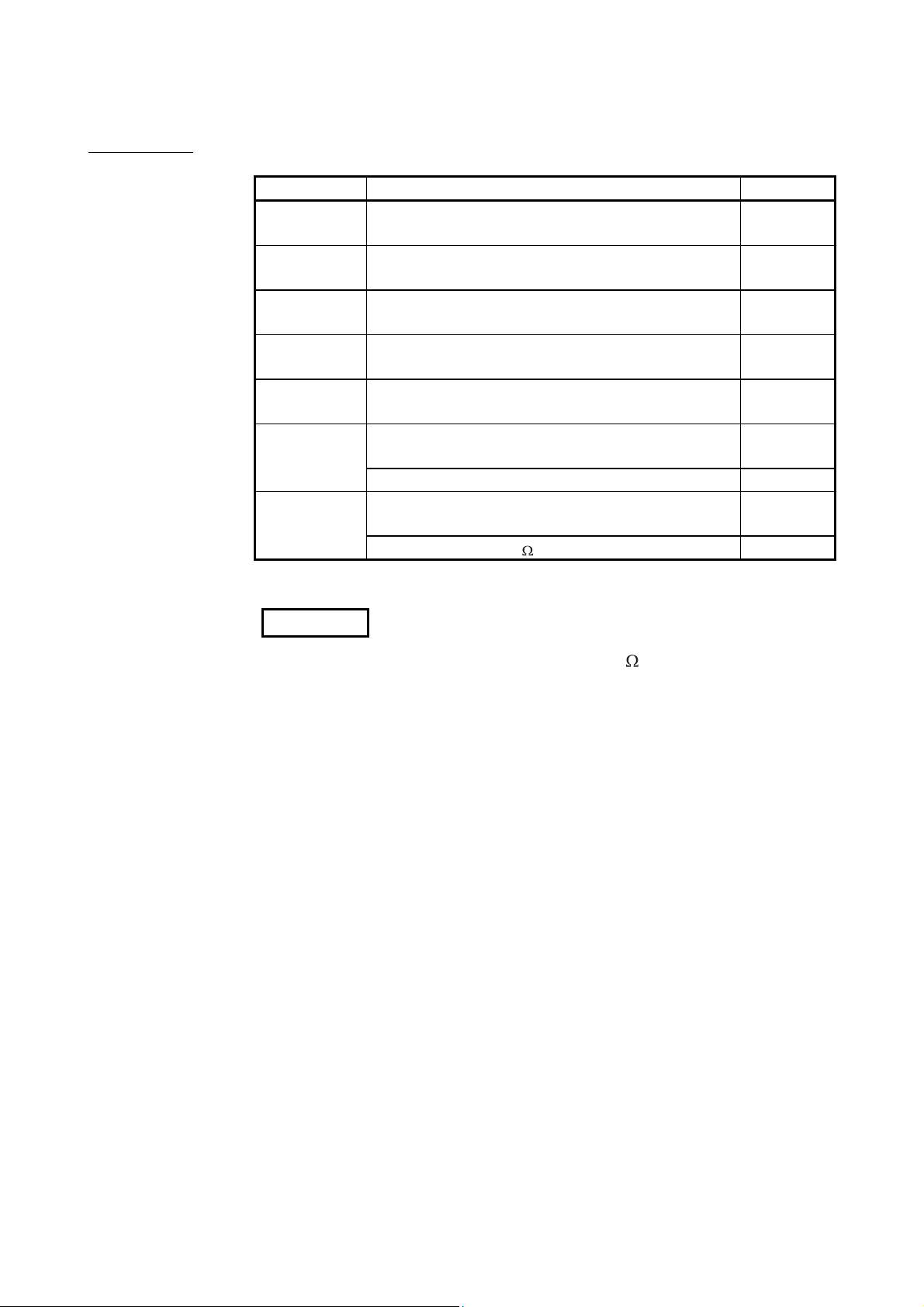
Terminating resistor 110 , 1/2W (brown, brown, brown) 1
*1: The QJ71LP21 is discontinued in October, 2000.
1
1
1
1
1
1
1
REMARKS
For the coaxial bus system, terminating resistors (75 ) are required in the network
terminal stations.
Terminating resistors are not supplied with the QJ71BR11; they must be purchased
separately.
For a list of the model names and how to use the terminating resistors, refer to
Section 4.6.2.
A - 19 A - 19

1 OVERVIEW
1 OVERVIEW
MELSEC-Q
1
1.1 Overview
The MELSECNET/H network system includes a PLC to PLC network for
communicating between the control station and normal stations, and a remote I/O
network for communicating between the remote master station and remote I/O stations.
This manual is used for configuring PLC to PLC networks on MELSECNET/H network
systems (hereinafter abbreviated as MESECNET/H.)
When configuring a remote I/O network using MELSECNET/H, refer to Q
corresponding MELSECNET/H Network System Reference Manual (Remote I/O
network).
REMARKS
Networks known as MELSECNET/10H are hereinafter abbreviated as
MELSECNET/H.
The PLC to PLC network system of MELSECNET/H provides more functionality,
higher processing speed and more capacity than the conventional PLC to PLC network
system of MELSECNET/10 network system.
In addition, in pursuit of the maximum ease of use of the MELSECNET/10 network
system, the FA system can be networked easily by combining with GX Developer.
The MELSECNET/H system supports the MELSECNET/H and MELSECNET/H
Extended modes (high functionality and high-speed mode) and the MELSECNET/10
mode (functional and performance compatibility mode) to achieve the network
performance improvement and upward compatibility of MELSECNET/10.
Unless otherwise categorized, this is abbreviated as MELSECNET/H for explanatory
purposes in this manual.
1 - 1 1 - 1
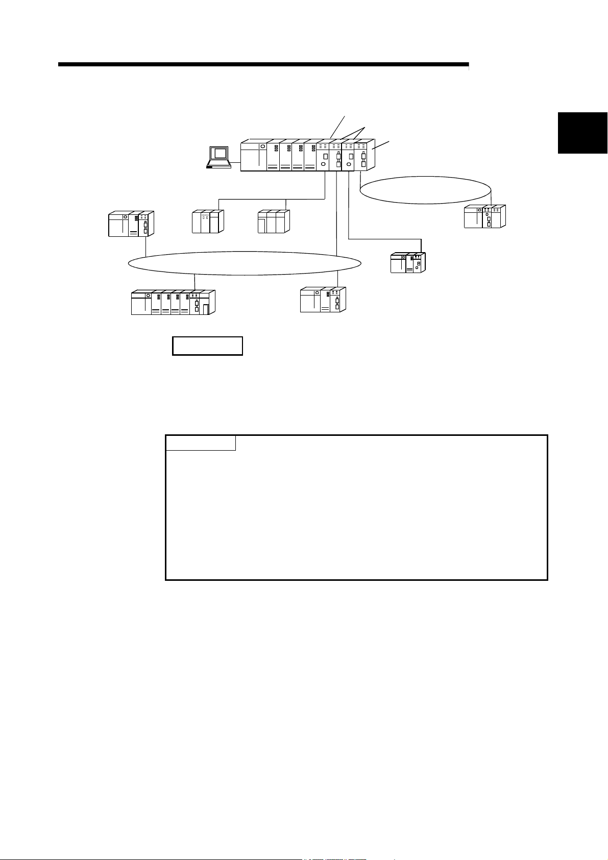
1 OVERVIEW
GX Developer
Q25HCPU
MELSEC-Q
Control station (MELSECNET/10 mode)
Control station (MELSECNET/H mode)
Remote master station
1
MELSECNET/10
Q25HCPU Normal station
QnACPU
MELSECNET/H (25Mbps) PLC to PLC network
Q25HCPU
PLC to PLC network
Normal
station
AnUCPU
Normal station
Normal
station
Q25HCPU
REMARKS
MELSECNET/H (25Mbps)
remote I/O network
MELSECNET/H (10Mbps)
PLC to PLC network
Q25HCPU
Normal station
Normal station
Remote I/O
station
This manual is written assuming that MELSECNET/H is used in the MELSECNET/H
or MELSECNET/H Extended mode. Thus, if MELSECNET/H is to be used in the
MELSECNET/10 mode, please refer to the "For QnA/Q4AR MELSECNET/10
Network System Reference Manual".
POINT
(1) Select a QCPU as a programmable controller of the MELSECNET/H for PLC
to PLC network system.
(2) When any of the conventional series QnA, AnU and ACPUs exist in the same
network, select the MELSEC NET/10 mode, which is compatible with the
MELSECNET/10.
(3) Set the control station and normal stations within the same network to the
same network type.
Stations of different network types cannot be used together within the same
network.
1 - 2 1 - 2
1 OVERVIEW
module
QCPU
AnUCPU MELSECNET/10
QnACPU MELSECNET/10
MELSEC-Q
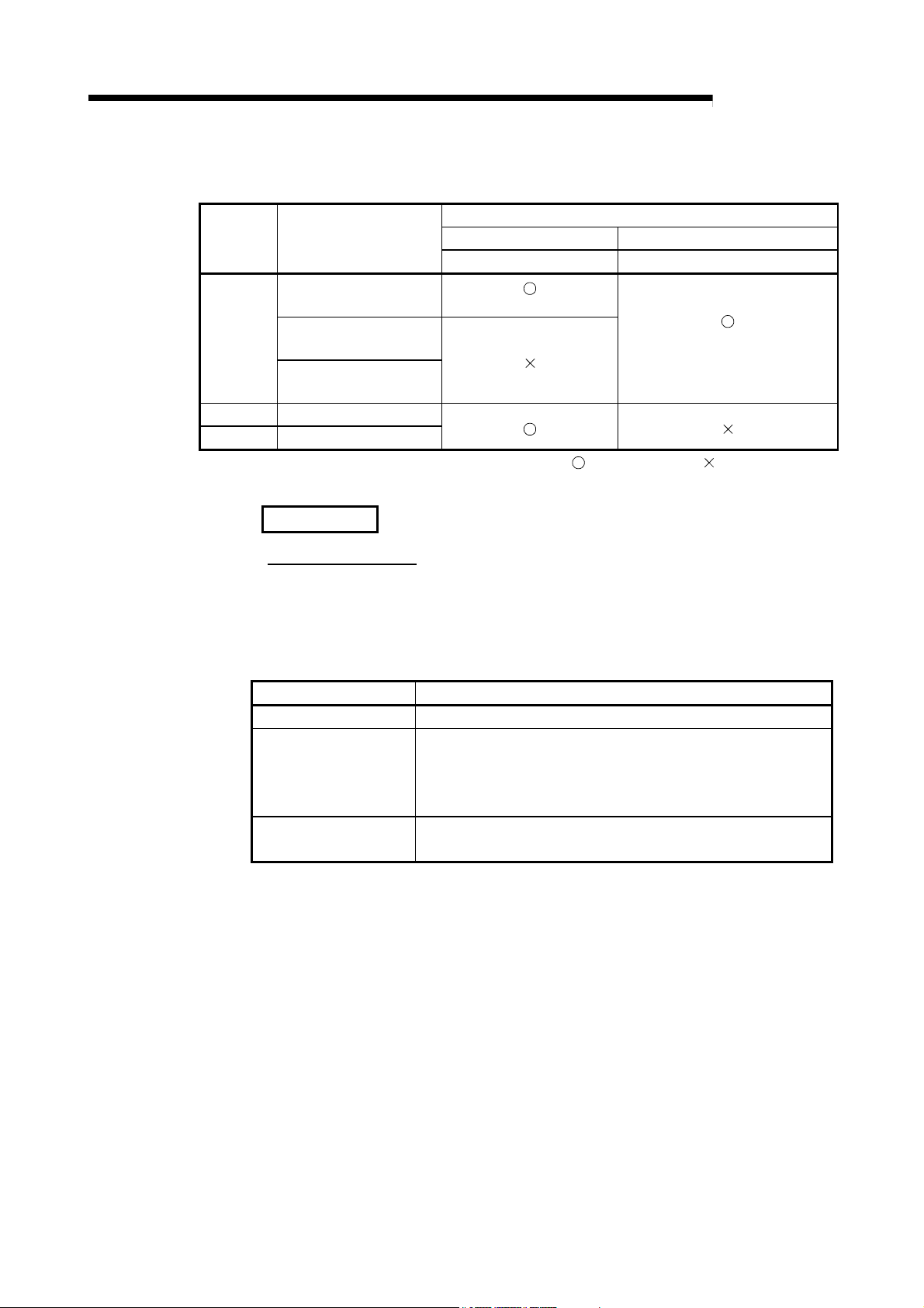
The table below shows the CPU modules that can be combined for use on each
network.
CPU
Type of networks that can
be used with CPU
MELSECNET/H
(10 Mbps)
MELSECNET/H
(25 Mbps)
MELSECNET/H
(Twisted bus)
MELSECNET/10 MELSECNET/H
PLC to PLC network PLC to PLC network
(MESLECNET/10 mode)
Network to be connected
(MESLECNET/H mode,
MELSECNET/H Extended mode)
: Use possible : Use not possible
REMARKS
What is network type?
The network type is a parameter set for specifying the network where the network
module is used.
Set the network type of the network module in the Network parameter of GX
Developer.
There are the following network types.
Network type Description
MELSECNET/H mode Set this mode when all CPUs within the network are QCPUs.
The maximum number of link points per station has been increased
MELSECNET/H Extended
mode
MELSECNET/10 mode
compared with the MELSECNET/H mode.
In excess of 2000 bytes, a maximum of 35840 bytes can be set.
Set this mode when the system uses many link points per station.
This mode is used to operate the network module on a
MELSECNET/10 network where the QnA/AnU exists.
1 - 3 1 - 3
1 OVERVIEW
1.2 Features
The MELSECNET/H is designed to provide higher processing speed, more capacity,
and more functionality while maintaining the connectivity with the MELSECNET/10; it is
easier to use than ever in combination with GX Developer. Furthermore, the
MELSECNET/H has the following features that were not available with the conventional
MELSECNET (II) and MELSECNET/B data link systems.
(1) Achievement of a high-speed communication system
(a) The MELSECNET/H enables high-speed communications with 25Mbps
and 10Mbps communication speeds.
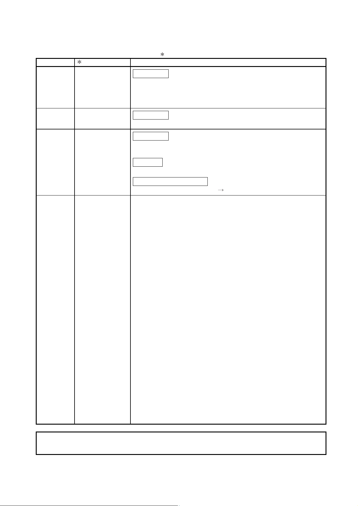
Item
Link device transfer 8 16 64
SB/SW transfer 1 for each
Basic model QCPU
Safety CPU
Refresh range
Communication speeds vary depending on the network system.
Network system Communication speed
Optical loop 10Mbps or 25Mbps 1
Coaxial bus 10Mbps
Twisted bus 156kbps to 10Mbps
1: QJ71LP21-25 and QJ71LP21S-25 only
(b) The link scan time has become even faster through the use of processors
specifically designed for linking.
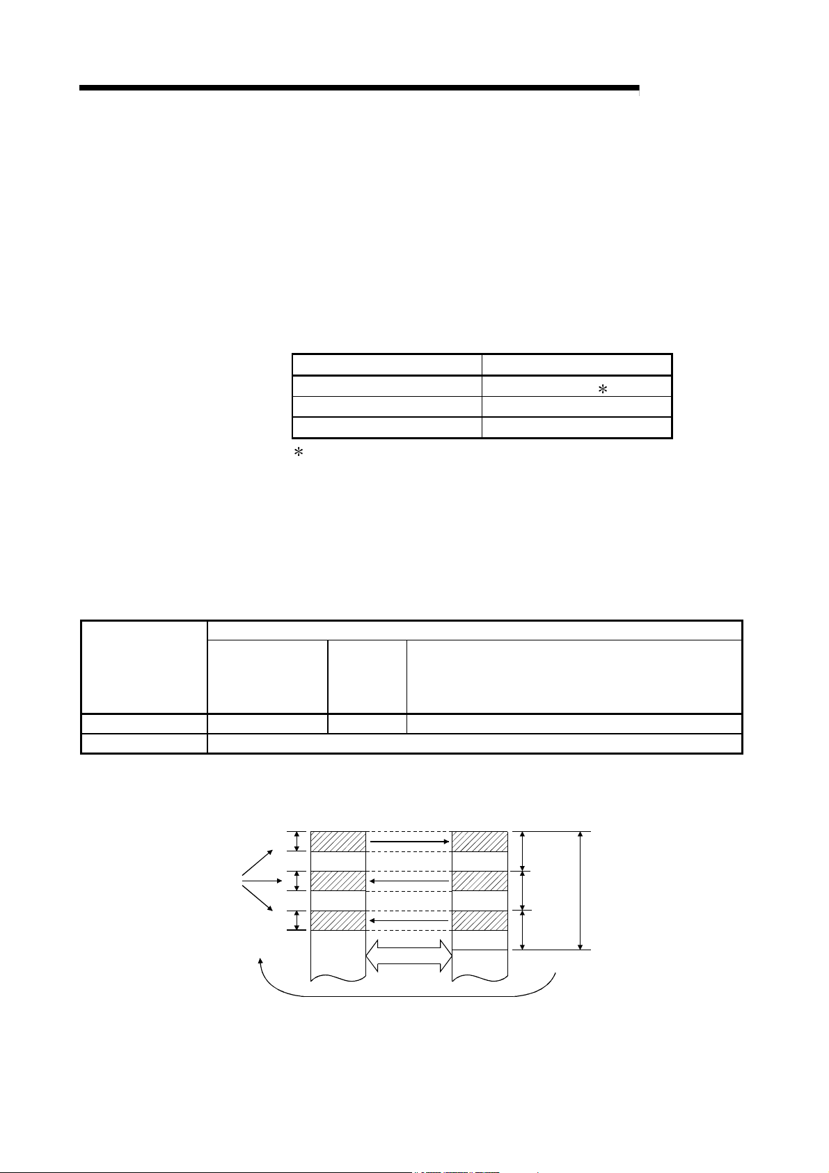
(c) Refresh parameter area can be subdivided
By subdividing ranges refresh parameter ranges, refreshing of the areas
not used for the sequence program can be eliminated and the refresh time
can be reduced by refreshing only those required. (Refer to Section 5.7
"Refresh Parameters.")
The number of refresh parameter settings per module is shown below.
Number of settings
Q00UJCPU
Q00UCPU
Q01UCPU
Universal model QCPU other than listed in the left column.
High Performance model QCPU
Process CPU
Redundant CPU
Also, because the bus speed between a QCPU and a network module has
been improved, the refresh time has been reduced.
QCPU
device (B)
Network module
link device (LB)
Station
No. 1
(Host)
Station
No. 2
MELSEC-Q
Each station's
total send range
Station
No. 3
High-speed bus
Fragmentation
(d) The optical loop system enables even faster levels of data communication
with multiplex transmission (refer to Multiplex Transmission Function in
section 7.6.)
1 - 4 1 - 4
1 OVERVIEW
MELSEC-Q
(2) Large-scale and flexible system configuration
(a) The link device has a larger capacity: 16384 points for the link relay (LB)
and 16384 points for the link register (LW). (Refer to Section 3.1.1)
(b) The maximum number of link points per station has been increased.
By selecting the network type, the maximum number of link points per
station can be increased.
1) MELSECNET/H Extended mode
By selecting the MELSECNET/H Extended mode as the network type,
the maximum number of link points per station can be set up to 35840
bytes in excess of 2000 bytes.
It is not necessary to install multiple network modules for a single CPU
module to increase the number of transmission points.
2) MELSECNET/H mode
1
By selecting the MELSECNET/H mode as the network type, the
maximum number of link points per station can be set up to 2000 bytes.
Furthermore, by installing multiple network modules with the same
network number for the same CPU module, the link points of "number
of modules
maximum number of link points per station" can be sent.
(High Performance model QCPU, Process CPU, Redundant CPU, and
Universal model QCPU) (Refer to Section 7.9 "Increasing the Number
of Send Points by Installing Multiple Modules Having the Same
Network Number.")
1: The link scan time varies depending on the network type.
Refer to Section 3.3.2 for details.
(c) The commands for transmitting and receiving data with other stations on
the MELSECNET/H network system (SEND, RECV, RECVS, READ,
SREAD, WRITE, SWRITE) enable a maximum of 960 words of data to be
transmitted and received (refer to Programming in section 7.4.5.)
(d) A system can be expanded to contain a maximum of 239 networks. (Refer
to Section 2.1.4, "A Network System Containing Multiple Networks.")
(e) By using the inter-link data transfer function, data (LB/LW) can be transferred
to another network without creating a sequence program. (High Performance
model QCPU, Process CPU, Redundant CPU, and Universal model QCPU)
(Refer to Section 7.2, "Inter-link Data Transfer Function.")
Q25HCPU
Network
module 1
LB LB
0
Network
module 2
1
0
Inter-link data
Q25H
CPU
Network
module
Data of network No. 2
Network No. 1
3FFF
transfer
H
3FFF
Data of network No. 1
Q25H
CPU
H
Network No. 2
Network
module
1 - 5 1 - 5
1 OVERVIEW
GX Developer
Transient transmission
possible.
Q25H
CPU
MELSEC-Q
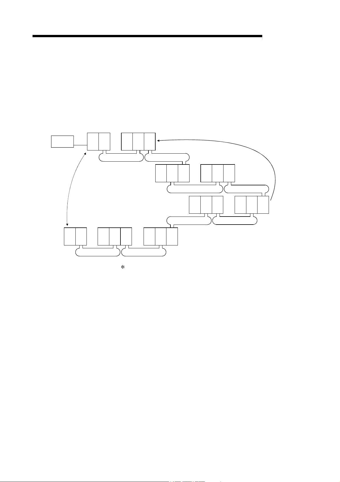
(f) By installing multiple network modules, N:N communication (transient
transmission) with destination stations on eight network systems that use
the programmable controllers as relay stations can be performed using the
routing function.
(Refer to Section 7.4.2, "Routing Function.")
Transient transmission using the routing function can be performed not only
in a system composed of MELSECNET/H networks but also in a system
that contains CC-Link IE Controller Network, CC-Link IE Field Network
and/or MELSECNET/10 networks.
QJ71
LP21
No.1
Q25H
CPU
MELSECNET/H
QJ71
LP21
QJ71
LP21
Request destination
MELSECNET/H
Q25H
QJ71
CPU
LP21
No.3
No.2
QJ71
LP21
Q25H
CPU
Q25H
CPU
QJ71
LP21
QJ71
LP21
QJ71
LP21
QJ71
LP21
MELSECNET/HMELSECNET/H
Q25H
CPU
QJ71
LP21
No.4
QJ71
LP21
Request
source
MELSECNET/ H MELSECNET/H
Q25H
CPU
QJ71
LP21
Q25H
CPU
QJ71
LP21
QJ71
LP21
Q25H
QJ71
LP21
No.7No.8
QJ71
LP21
CPU
MELSECNET/HMELSECNET/H
No.5No.6
: Only the High Performance model QCPU, Process CPU, Redundant
CPU, and Universal model QCPU accept multiple network modules.
(g) The following three types of network systems can be configured
according to applications of each user.
1) Loop system that is more resistant to noise and provides longer distance
in total and between stations. (Up to 30km in total length)
2) Coaxial bus system that allows easier wiring (Up to 500m in total length)
3) Twisted bus system that allows the use of general-purpose cables (Up to
1200m in total length)
(Refer to Section 3.1, "Performance Specifications.")
(h) The following functions facilitate network connection:
1) Any station to be connected in the future can be specified as a reserved
station.
Specifying a station not actually connected as a reserved station
prevents a communication error. (Refer to Section 5.3.4 "Specification of
the reserved station.")
2) It is not necessary to connect stations in order of the station Nos. in the
network. (Refer to Section 4.2 "Part Names and Settings.")
1 - 6 1 - 6
1 OVERVIEW
a
n
i
t
s
e
Network module
e
n
n
a
h
c
n
o
i
t
QCPU
Send
J.SEND
D
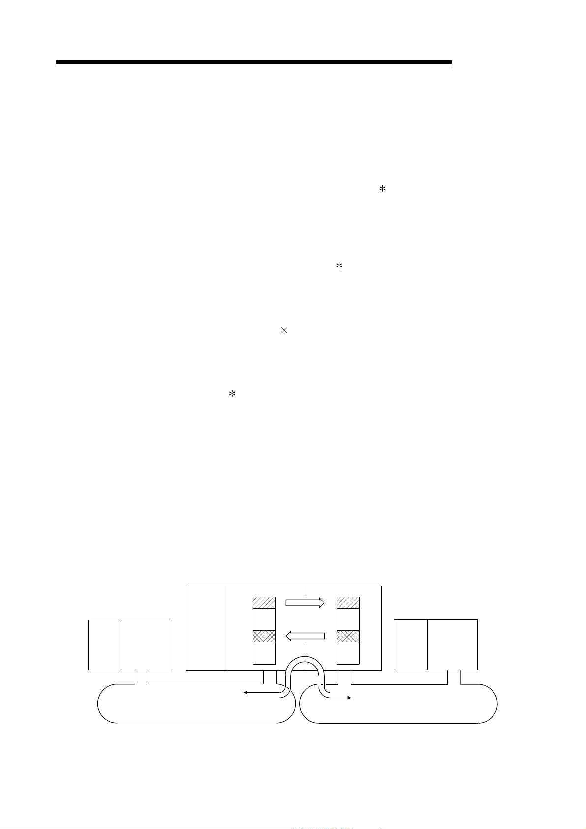
(3) Providing various communication services
(a) Transient transmission can be performed by designating a channel
number (1 to 64) of the receiving station. This function allows to set
(change) the channel numbers arbitrarily with the sequence programs and
to perform transmission to multiple stations with the same channel number
at one time.
(Refer to Section 7.4.4, "Message sending function using the logical
channel numbers.")
Receiver
channel
unmatched
Sender
9
.
o
N
l
Discard
Discard
Receiver
channel
No. 9
Received
Received
Received
MELSECNET/H
Receiver
channel
No. 9
QCPU
Channel 1
Channel
No.1
No.2
No.3
MELSEC-Q
2
3
7
8
Channel
No.9
No.20
Network module
Receive
J.RECV
Receiver
channel
unmatched
Receiver
channel
No. 9
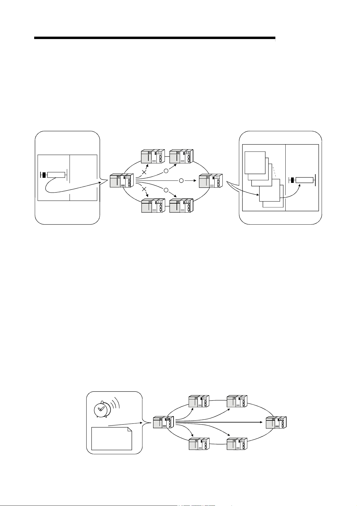
(b) By using the low-speed cyclic transmission function, it is possible to
cyclically send data that does not require high-speed transmission in a
batch mode, separately from the normal cyclic transmission (LB/LW). Highspeed transmission can be achieved by efficiently dividing the data to
transmit into data that requires high-speed transmission, which is sent by
the normal cyclic transmission, and other data that is sent by low-speed
cyclic transmission.
There are three types of transmission method depending on how the
transmission is activated.
1) "Transmission of data for one station in one link scan" (default)
2) "Periodical cycle interval" which transmits in a set time cycle
(hour/minute/second)
3) "System times" which transmits data at the specified timing
(year/month/day/hour/minute/second)
(High Performance model QCPU, Process CPU, Redundant CPU,
and Universal model QCPU)
(Refer to Section 7.3, "Low-Speed Cyclic Transmission Function.")
MELSECNET/H
T
g
i
s
e
d
e
h
t
e
m
i
t
d
e
t
a
n
t
a
n
o
i
s
s
i
m
s
n
a
r
Low-speed cyclic
transmission data
1 - 7 1 - 7
1 OVERVIEW
I50
Interrupt
sequence
program
MELSEC-Q
(c) The interrupt sequence program of the host's CPU module can be started
up using the event issue function. This function reduces the response time
of the system and process real-time data receiving. (Refer to Section 7.5,
"Starting Up the Interrupt Sequence Program.")
CPU module
IRET
MAIN
Normal
sequence
program
END
Conditions
matched
Network module
Condition check
Interrupt condition
parameters
• Relay information
• Register data
• Arrival at a channel
• Network status
MELSECNET/H
Transient transmission
from other station
Cyclic transmission
(4) Enhanced RAS functions (Refer to Section 3.2.2, "RAS function.")
(a) By using the control station switch function, if the control station of the
network is down, a normal station is substituted for the control station,
enabling to continue the network communication.
(b) When a faulty station recovers and can resume normal operation, it
automatically returns to the network to resume the data communication
using the automatic return function.
(c) The automatic return control function allows a failed control station to be
reconnected to the network as a normal station, reducing network downtime.
(d) The loopback function (in the optical loop system) isolates a faulty part,
where a fault such as cable disconnection or a station error has occurred,
and enables data communications among operable stations.
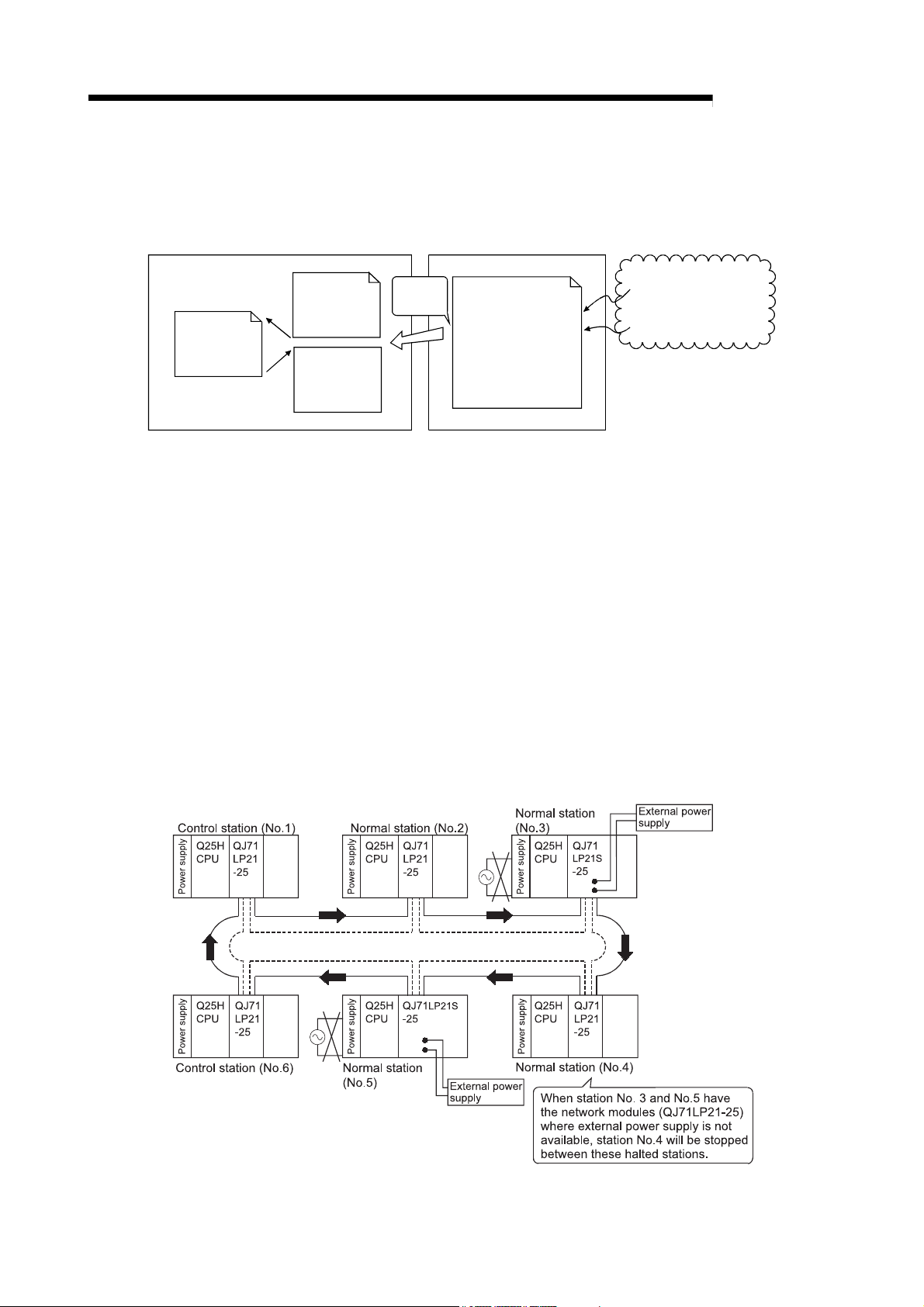
(e) Preventing station failure using external power supply
When two or more stations are faulty and halted in the optical loop system,
stations between these faulty stations can continue the data link.
Because the loop back is prevented, the link scan time will be stabilized.
(The QJ71LP21S-25 is the network module where external power can be
supplied.)
1 - 8 1 - 8

1 OVERVIEW
MELSEC-Q
(f) By using the station detach function (coaxial bus system and twisted bus
system), even when some of the connected stations are down due to power
off, etc., the normal communication can be continued among other
operational stations.
(g) W hen an error occurs in a normal network due to disconnection, etc. the
data link can be continued by switching to link data refresh on the standby
network if two network modules, a regular module and a standby module,
are installed for each programmable controller CPU (High Performance
model QCPU and Process CPU)
(h) The network module can continue the transient transmission even if an
error that stops the CPU module while the system is operating occurs.
(i) It is possible to check the time when a transient error occurred.
REMARKS
The following faults make the RAS functions valid.
Break in cable
Power-off of slave station
Network setting error
Fault detectable by self-diagnostics of CPU module
If the network module has become faulty, the RAS functions may not be activated
depending on the fault.
1 - 9 1 - 9
r
1 OVERVIEW
MELSEC-Q
(5) Enhancement and compatibility of the network functions
(a) Because of the 32-bit data assurance, data with double word precision
(32 bits) can be assured without an interlock.
(Refer to Section 6.2.1, "32-bit data assurance.")
CPU module
device W
Network module
LW
Updated part
of refresh A
Updated part
of refresh B
Updated part
of refresh C
Refresh A
Refresh B
Refresh C
Positional data 1 lower
higher
Positional data 2
Positional data 9
Positional data 10
lower
higher
lower
higher
lower
higher
Link refresh in
32-bit units
(b) Through the station-based block data assurance for cyclic data, it is
possible to manipulate multiple word data without interlocks.
(Refer to Section 6.2.2, "Station-based block data assurance for cyclic
data.")
CPU module
device W
Updated part
of refresh A
Refresh A
Network module
LW
Station No. 1
Updated part
of refresh B
Updated part
of refresh C
Refresh B
Refresh C
Station No. 2
(Host)
Station No. 3
Station No. 4
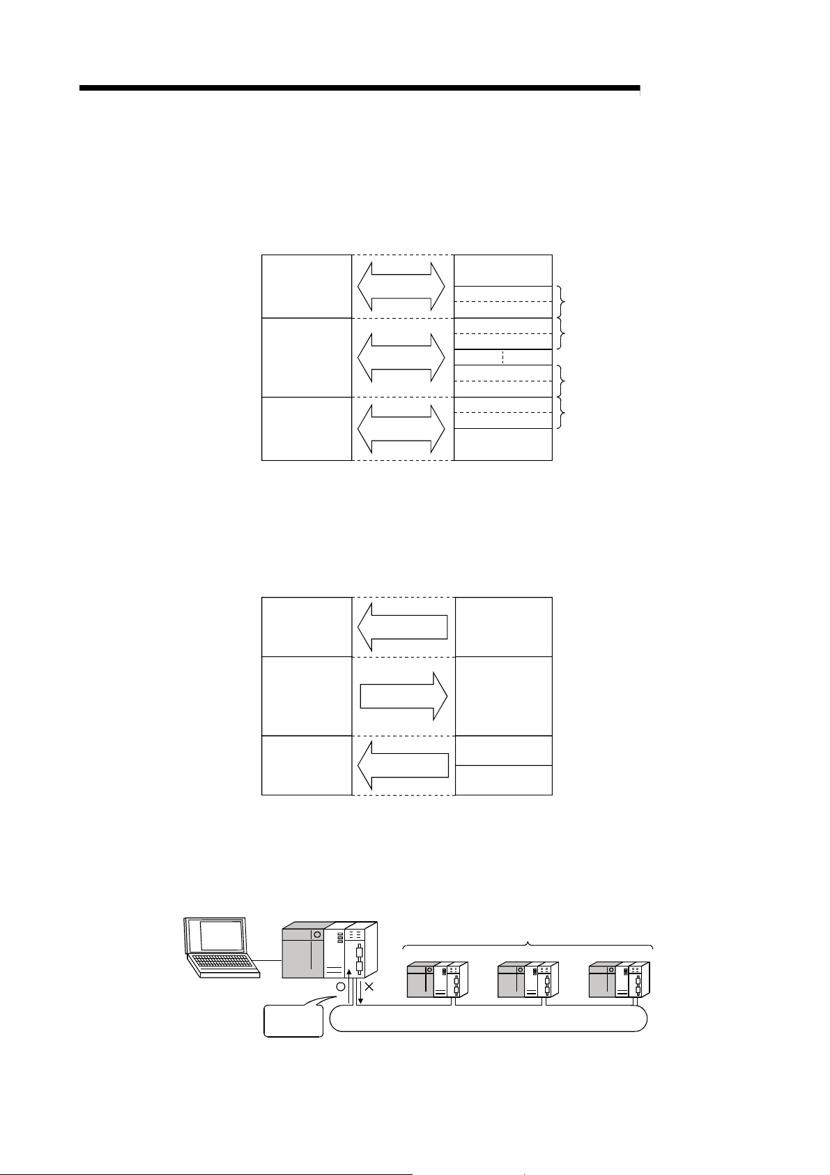
(c) In the network debug mode, the network functions of user programs can
be tested in the online environment without affecting systems being
operated.
(Refer to Section 5.2.5, "Mode.")
Being debuggedGX Develope
Data
receive
possible
LB/LW
Systems being operated
MELSECNET/H
1 - 10 1 - 10
1 OVERVIEW
MELSEC-Q
(d) By using the MELSECNET/10 mode (functional compatibility and
performance compatibility mode), the MELSECNET/H can be used
together with the conventional network modules to easily install a
programmable Controller Network system.
To use the MELSECNET/H in the MELSECNET/10 mode (functional
compatibility and performance compatibility mode), please refer to the "For
QnA/Q4AR MELSECNET/10 Network System Reference Manual".
QnACPU
QCPU QCPU QCPU
MELSECNET/H
QCPU
A2USCPU
MELSECNET/10
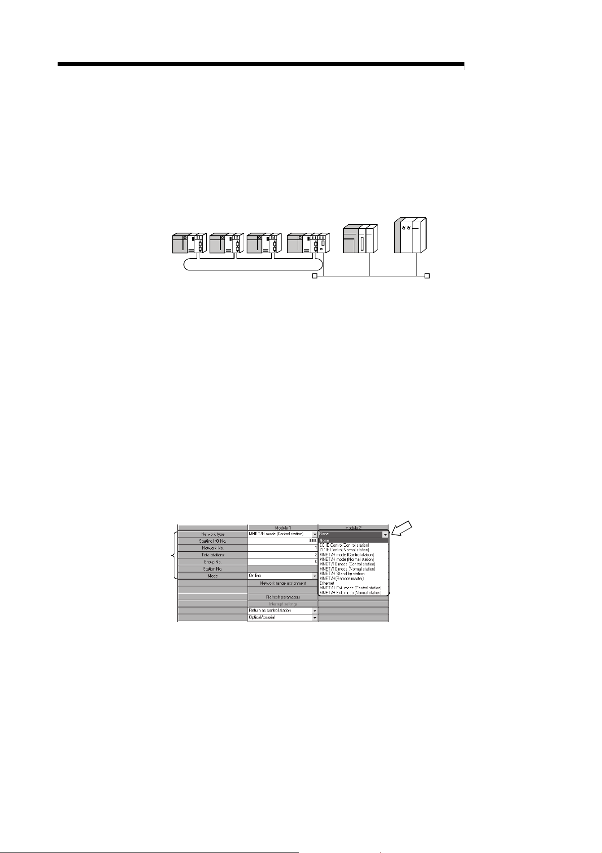
(6) Increased ease of network configuration in combination with GX
Developer
(a) The network parameters can easily be set by visualizing pull-down menus,
dialogue boxes, etc.
(b) The settings of network Nos., group numbers and operation modes have
been simplified so that these values can be specified only through software
settings.
(c) On the twisted bus system, the transmission speed setting for the normal
station is not required.
The normal station operates with the transmission speed set to the control
station.
(Refer to Section 5.2.6, "Communication speed setting.")
(Network parameters)
Pull-down menu
Simplified
1 - 11 1 - 11

1 OVERVIEW
MELSEC-Q
(c) Troubleshooting process has been simplified through system monitoring.
(System monitor/error code display)
Displays the latest error code.
Displays error history.
Displays the description and corrective
action of the error code selected in error
history.
(d) After assigning the refresh parameters and inter-link data transfer devices
to a network system in which multiple network modules are installed,
duplicate device settings can easily be checked with [Assignment image
diagram].
1 - 12 1 - 12

1 OVERVIEW
MELSEC-Q
(7) Redundant system configuration
(a) Network modules can be dualized.
A system containing a network module can be dualized (redundant system)
by installing another network module and using redundant CPUs.
In case of an error in the control system CPU or a network module, the
redundant system including double network modules switches the control
system to the standby system, allowing system control and data linking to
be continued on the standby system. (Refer to Section 7.10.1.)
(b) Automatically issuing system switching request to the control system CPU
If failure of a network module mounted to the control system CPU of the
redundant system or a data link error is detected, a system switching
request will be automatically issued to the CPU. (Refer to Section 7.10.5.)
(c) Transient transmission to redundant system is available.
By transient transmission using special link instructions or GX Developer,
device data can be read from or written to the host system, control/standby
system, or system A/B in the redundant system, and remote RUN/STOP
can be executed. (Refer to Section 7.4.5.)
When the redundant system is a target station, even if system switching
occurs, the target can be followed by specifying the CPU type of the station
to control or standby system.
MELSECNET/H PLC to PLC network
Control system Standby system
MELSECNET/H remote I/O network
1 - 13 1 - 13

1 OVERVIEW
1.3 Symbols Used in This Manual
MELSEC-Q
Generic terms and
abbreviations for CPU
modules
Basic model QCPU
High Performance model
QCPU
Process CPU
Redundant CPU
Universal model QCPU
Safety CPU
C Controller module
Other than Redundant
CPU
Other than Universal
model QCPU
Other than Safety CPU
(1) Symbols
Symbol Name
MP Control station
NS Normal station (Station that can serve as a control station)
(2) Symbol format
M
P
Group number (1 to 32): G
Station number (1 to 64)
Symbol
Network number (1 to 239)
[Example]
1) Network No. 3, control station, station number 6: 3M
2) Network No. 5, normal station, station number 3: 5N
(3) Generic terms and abbreviations for CPU modules
CPU model
Q03UDE
Q04UDEH
Q06UDEH
Q10UDEH
Q13UDEH
Q20UDEH
Q26UDEH
Q50UDEH
Q100UDEH
Q03UDV
Q04UDV
Q06UDV
Q13UDV
Q26UDV
Q00J
Q00
Q01
Q02U
Q02
Q02PH
Q02H
Q06PH
Q06H
Q12PH
Q12H
Q25PH
Q25H
Q12PRH
Q25PRH
Q00UJ
Q00U
Q01U
Q03UD
Q04UDH
Q06UDH
Q10UDH
Q13UDH
Q20UDH
Q26UDH
QS001
P6
S3
Q06CCPU-V
Q06CCPU-V-B
Q12DCCPU-V
Q24DHCCPU-V
Q24DHCCPU-VG
Q24DHCCPU-LS
Q26DHCCPU-LS
1 - 14 1 - 14

2 SYSTEM CONFIGURATION
2 SYSTEM CONFIGURATION
MELSEC-Q
2.1 MELSECNET/H Network Configurations
This section describes network configurations available with the MELSECNET/H.
This chapter explains system configurations available with the MELSECNET/H.
2
2.1.1 Single network system
A single network system is the system where the control station and normal stations
are connected with any of the following cables.
Optical loop system: Optical fiber cable
Coaxial bus system: Coaxial cable
Twisted bus system: Shielded twisted pair cable or CC-Link Ver. 1.10-compatible
cable.
(1) Optical loop system
In the optical loop system, 1 control station and 63 normal stations (a total of 64
stations) can be connected.
Any station number can be assigned as the control station.
Note that only one station can be set as the control station per system.
In the following sample system, station number 1 is assigned as the control
station.
Station No.1
(control station)
Station No. 2
(normal station)
Station No. 64
(normal station)
QCPU
Power supply
QJ71
LP21
QCPU QJ71
Power supply
LP21
QCPU QJ71
LP21
Power supply
Optical fiber cable
(2) Coaxial bus system
In the coaxial bus system, 1 control station and 31 normal stations (a total of 32
stations) can be connected.
Any station number can be assigned as the control station.
Note that only 1 station can be assigned as the control station per system.
Station No.1
(control station)
QJ71
BR11
Power supply
Station No. 2
(normal station)
QCPU QCPUQCPU
Power supply
QJ71
BR11
Station No. 32
(normal station)
QJ71
BR11
Power supply
Coaxial cable
Terminating resistor
A6RCON-R75
Terminating resistor
A6RCON-R75
2 - 1 2 - 1

2 SYSTEM CONFIGURATION
MELSEC-Q
(3) Twisted bus system
In the twisted bus system, 1 control station and 31 normal stations (a total of 32
stations) can be connected.
Any station number can be assigned as the control station.
Note that, only 1 station can be assigned as the control station per system.
Station No.1
(control station)
QJ71
QCPU
NT11B
Power supply
Terminating
Twisted pair cable or CC-Link Ver.1.10-compatible cable
resistor
Station No.2
(normal station)
QJ71
QCPU
NT11B
Power supply
Station No.32
(normal station)
QJ71
QCPU
NT11B
Power supply
Terminating
resistor
2
POINT
A safety CPU operates as a normal station. (It cannot be set to a control station.)
2 - 2 2 - 2

2 SYSTEM CONFIGURATION
2.1.2 Redundant system (Redundant CPU)
The redundant system refers to a system where a system including a network module
is dualized by connecting another network module to another redundant CPU
(redundant system).
If failure of the control system CPU or a network module occurs, the redundant system
switches the control system to the standby system, allowing system control and data
linking to be continued on the standby system.
For details, refer to Section 7.10.1.
MELSECNET/H PLC to PLC network
MELSEC-Q
Control system Standby system
MELSECNET/H remote I/O network
POINT
The QJ71NT11B does not support the Redundant CPU.
2 - 3 2 - 3
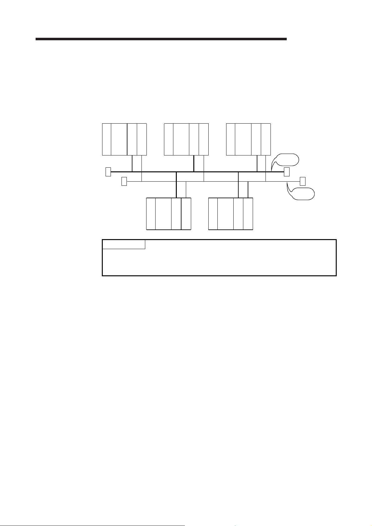
2 SYSTEM CONFIGURATION
MELSEC-Q
2.1.3 Simple dual-structured system (High Performance model QCPU and Process CPU)
In a simple dual-structured system, "regular" and "standby" network modules are
installed in each CPU module, so that if the regular network is down, the data link can
still be continued by switching to the standby network through link data refresh.
For details, refer to Section 7.7.
Control station Normal station Normal station
Power supply
Q25H
CPU
Regular
Standby
Network No. 1
Power supply
Q25H
CPU
Power supply
Q25H
CPU
Regular
Regular
Standby
Network No. 2
Standby
POINT
Simple dual-structured system cannot be configured with the Basic model QCPU,
Redundant CPU, and Universal model QCPU. These CPUs are applicable for a
single network system.
Q25H
CPU
Power supply
Q25H
Power supply
CPU
Regular
Standby
Regular
Standby
Regular
network
Standby
network
2 - 4 2 - 4

2 SYSTEM CONFIGURATION
MELSEC-Q
2.1.4 Multiple network system (High Performance model QCPU, Process CPU, Redundant CPU, and Universal model QCPU)
(1) What is multiple network system
The multiple network system is a network system in which multiple networks are
connected via relay stations.
(a) Duplicated setting of a network number is not allowed. The network
number can be freely set within a range from 1 to 239 unless the same
number is used two or more times in a system.
(b) A maximum of 4 network modules can be installed per programmable
controller.
Note that there are restrictions on the number of modules that can be
installed to each programmable controller, depending on the CPU module
model. (Refer to the user's manual for the CPU module used.).
Control station
Q25H
CPU
Power supply
1M
QJ71
LP21
P1
POINT
Network No. 1
Network No. 2
1st
2nd
module
4th
3rd
module
module
Network No. 3
module
Network No. 4
Only one network module can be mounted to the Basic model QCPU, Q00UJCPU,
Q00UCPU, Q01UCPU, and safety CPU.
For this reason, these CPUs cannot be used as relay stations when configuring a
multiple network system using the MELSECNET/H.
(2) Configuration
The following example shows how three networks can be connected.
Network No. 1
Normal station
Q25H
CPU
Power supply
S2
1N
QJ71
LP21
Control station
2M
P1
QJ71
LP21
Network No. 2
Normal station
Q25H
CPU
Power supply
2N
S2
QJ71
LP21
QJ71
LP21
S3
1N
QJ71
BR11
Control station
3M
1
P
Q25H
CPU
Power supply
Normal station
QJ71
BR11
3N
S
Network No. 3
Q25H
QJ71
CPU
BR11
Power supply
2
3NS3
Normal station
Q25H
CPU
Power supply
Normal
station
Q25H
CPU
Power supply
Normal station
QJ71
BR11
3NS4
Power supply
Q25H
CPU
QJ71
LP21
Normal station
2N
S3
2 - 5 2 - 5

2 SYSTEM CONFIGURATION
2.2 Applicable Systems
This section describes the applicable systems.
No. of mountable modules is the maximum number of mountable network modules
with CC-Link IE Controller Network.
(1) Applicable modules and base units, and number of mountable
modules
(a) When mounted with a CPU module
Refer to the user’s manual for the CPU module used.
Observe the following:
• Use the network module which satisfies the following conditions for the
Redundant CPU.
• Use the network module which satisfies the following conditions for the
safety CPU.
• A shortage of the power capacity may result depending on the
combination of mounted modules or the number of mounted modules.
When mounting modules, consider the power capacity. If the power is
insufficient, change the combination of modules.
• Mount modules so that the total number of I/O points does not exceed the
point range of the CPU module. Modules can be mounted in any slot
within the applicable range.
• Function version D or later
• Network modules other than the QJ71NT11B
• Serial number (first five digits) "08102" or later
• Function version D or later
• Network modules other than the QJ71NT11B
MELSEC-Q
REMARKS
When mounted with a C Controller module, refer to the user’s manual for the C
Controller module used..
(b) When mounted on a MELSECNET/H remote I/O station
The network module cannot be mounted on a MELSECNET/H remote I/O
station.
Mount it with a CPU module on the master station.
(c) When mounted on an RQ extension base unit
Refer to the MELSEC iQ-R Module Configuration Manual.
(2) Support of the multiple CPU system
Before using the network module in a multiple CPU system, refer to the QCPU
User’s Manual (Multiple CPU System).
To configure the MELSECNET/H with a multiple CPU system, use a network
module of function version B or later.
For precautions for the use in a multiple CPU system, refer to Section 2.2.2.
2 - 6 2 - 6

2 SYSTEM CONFIGURATION
(3) Compatible network modules
Available network types and systems vary depending on the function version of
Basic model QCPU
High Performance model
QCPU
Process CPU
Redundant CPU Redundant system
Universal model QCPU
Safety CPU Single CPU system
Basic model QCPU
High Performance model
QCPU
Process CPU
Redundant CPU Redundant system Not supported
Universal model QCPU
Safety CPU Single CPU system Not supported
the network module.
(a) When optical loop system or coaxial bus system is used
MELSECNET/H Extended mode
Single CPU system
Multiple CPU system Function version B or later
Single CPU system Function version A or later
Multiple CPU system Function version B or later
Single CPU system Function version A or later
Multiple CPU system Function version B or later
Single CPU system
Multiple CPU system Function version B or later
Function version D or later
(Serial number (first five digits)
"06092" or later)
Function version D or later
(Serial number (first five digits)
"07102" or later)
Function version D or later
(Serial number (first five digits)
"06092" or later)
Function version D or later
(Serial number (first five digits) "08102" or later)
(b) When twisted bus system is used
MELSECNET/H Extended mode MELSECNET/H mode
Single CPU system
Multiple CPU system
Single CPU system
Multiple CPU system
Single CPU system
Multiple CPU system
Single CPU system
Multiple CPU system
From the first version
From the first version
MELSEC-Q
MELSECNET/H mode
MELSECNET/10 mode
Function version A or later
Function version D or later
Function version A or later
2 - 7 2 - 7
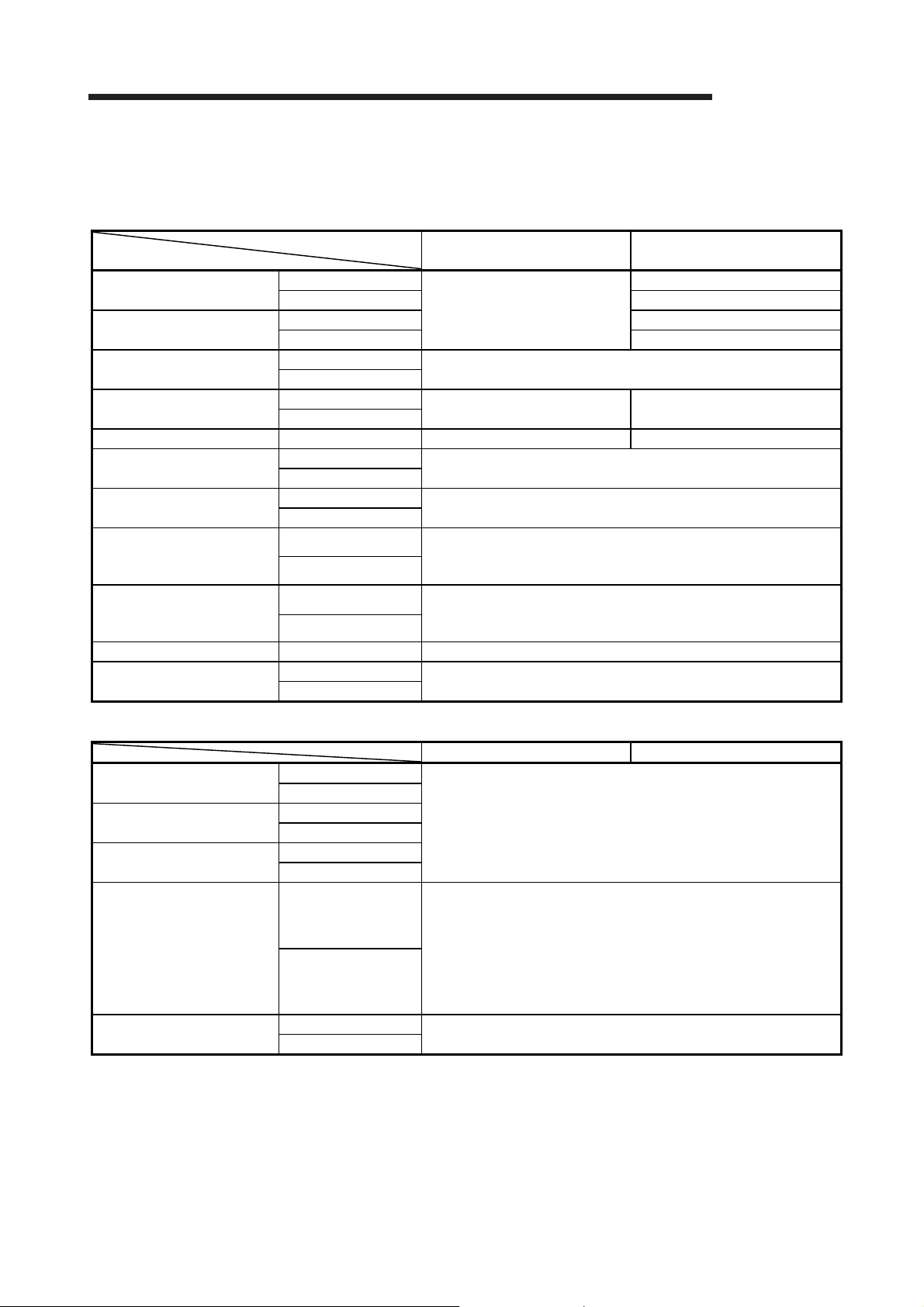
2 SYSTEM CONFIGURATION
MELSEC-Q
(4) Compatible software packages (when using GX Developer)
The systems using network modules and compatible software packages are
Q00J/Q00/Q01CPU
Q02/Q02H/Q06H/
Q12H/Q25HCPU
Q02PH/Q06PHCPU
Q12PH/Q25PHCPU
Q12PRH/Q25PRHCPU Redundant system Version 8.29F or later Version 8.18U or later
Q02U/Q03UD/Q04UDH/
Q06UDHCPU
Q13UDH/ Q26UDHCPU
Q03UDE/Q04UDEH/
Q06UDEH/Q13UDEH/
Q26UDEHCPU
Q00UJ/Q00U/Q01U/
Q10UDH/Q20UDH/
Q10UDEH/Q20UDEHCPU
QS001CPU Single CPU system Version 8.40S or later
CPU modules other than the
above
shown in the table below.
(a) When the optical loop system or coaxial bus system is used
MELSECNET/H Extended mode
Single CPU system
Multiple CPU system Version 8 or later
Single CPU system Version 4 or later
Multiple CPU system Version 6 or later
Single CPU system
Multiple CPU system
Single CPU system
Multiple CPU system
Single CPU system
Multiple CPU system
Single CPU system
Multiple CPU system
Single CPU system
Multiple CPU system
Single CPU system
Multiple CPU system
Single CPU system
Multiple CPU system
Version 8.20W or later
Version 8.68W or later
Version 8.20W or later Version 7.10L or later
Version 8.48A or later
Version 8.62Q or later
Version 8.68W or later
Version 8.78G or later
Not supported
MELSECNET/H mode
MELSECNET/10 mode
Version 7 or later
Q00J/Q00/Q01CPU
Q02/Q02H/Q06H/
Q12H/Q25HCPU
Q02PH/Q06PH/
Q12PH/Q25PHCPU
Q00UJ/Q00U/Q01U/Q02U/
Q03UD/Q04UDH/Q06UDH/
Q10UDH/Q13UDH/Q20UDH/
Q26UDH/Q03UDE/
Q04UDEH/Q06UDEH/
Q10UDEH/Q13UDEH/
Q20UDEH/Q26UDEHCPU
CPU modules other than the
above
(b) When the twisted bus system is used
MELSECNET/H Extended mode MELSECNET/H mode
Single CPU system
Multiple CPU system
Single CPU system
Multiple CPU system
Single CPU system
Multiple CPU system
Single CPU system
Multiple CPU system
Single CPU system
Multiple CPU system
Version 8.78G or later
Version 8.78G or later
Not supported
(5) Compatible software packages (when using GX Works2)
For a system with a network module and GX Works2 version, refer to the
following manual.
• GX Works2 Version 1 Operating Manual (Common)
2 - 8 2 - 8

2 SYSTEM CONFIGURATION
2.2.1 Precautions when using link dedicated instructions
When accessing to other stations from MELSECNET/H network modules (who issue
the request) with function version B or later upon link dedicated instructions, the
handling methods are different depending on the module of the target station.
The handling methods for each module of the target station are explained below.
(1) Link dedicated instructions modified for function version B
The data length of the SEND, READ, SREAD, WRITE and SWRITE instructions
is changed (480 words 960 words.)
(a) When the target station is a network module
Target station
Request issued by
480 words or less
481 to 960 words
CC-Link IE
Controller
Network
module
CC-Link IE
Field Network
module
MESLECNET/H network module
Function version B or D Function version A
: Processed normally
: Ends abnormally. Error code returned to the request source.
1: The SEND instruction ends abnormally. Error code returned to the
request source.
The READ, SREAD, WRITE, and SWRITE instructions are processed
normally.
(b) When the target station is a Q series Ethernet module
Target station (Q series Ethernet module)
Request issued by
480 words or less
481 to 960 words
: Processed normally
: Ends abnormally. Error code returned to the request source.
1: The SEND instruction ends abnormally. Error code returned to the
request source.
The READ, SREAD, WRITE, and SWRITE instructions are processed
normally.
2: The operations for the SEND instruction are not normal. (Error support
available F7C3
The READ, SREAD, WRITE, and SWRITE instructions are processed
normally.
3: Serial number (first five digits)
Function version D
07082 or later
3
)
H
07081 or earlier
MELSEC-Q
MESLECNET/10
network module
1
Function
3
1
version B
1
Function
version A
2
2 - 9 2 - 9

2 SYSTEM CONFIGURATION
(2) Instructions added for function version B
CC-Link IE
Request issued by
RRUN, RSTOP, RTMRD, RTMWR
Controller
Network
module
: Processed normally.
: Ends abnormally. Error code returned to the request source.
CC-Link IE
Field Network
module
Target station
MELSECNET/
H network
module
MELSECNET/
10 network
module
MELSEC-Q
Q series
Ethernet
module
2 - 10 2 - 10

2 SYSTEM CONFIGURATION
2.2.2 Precautions when using network modules in the multiple CPU system
Pay attention to the following points when configuring a MELSECNET/H network
system with a multiple CPU system.
(1) Set the network parameters in the control CPU that controls the network
modules.
(2) A maximum of four network modules can be set for each control CPU module.
Note that a total of four network modules can be mounted in the multiple CPU
system.
(a) CPU No.1 controls all network modules.
CPU
CPU
QJ71
QJ71
No.1
No.2
BR11
BR11
QJ71
BR11
QJ71
BR11
(b) CPU No.1 and CPU No.2 control network modules
separately.
CPU
No.1
CPU
No.2
QJ71
BR11
QJ71
BR11
MELSEC-Q
QJ71
QJ71
BR11
BR11
(c) CPU No.1 to CPU No.4 control each network module. (d) Up to 4 network modules can be mounted on the system.
CPU
No.1
CPU
No.2
CPU
No.3
CPU
No.4
QJ71
BR11
QJ71
BR11
QJ71
BR11
QJ71
BR11
CPU
CPU
No.1
No.2
: The number of modules exceeded the limit.
QJ71
BR11
QJ71
BR11
QJ71
BR11
QJ71
BR11
QJ71
BR11
2 - 11 2 - 11

2 SYSTEM CONFIGURATION
(3) Precautions for execution of transient transmission
(a) Access range of GX Developer
When connecting GX Developer to a CPU module and accessing other
stations, it is possible for GX Developer to access up to the 8 network
systems whether the relay stations on the multiple CPU system are control
or non-control CPUs.
(Refer to 7.4.2 Routine Functions in section)
It is also possible for GX Developer to access either a control or non-control
1) Relaying is possible if the relay station's control CPU is
the same
GX Developer
CPU
CPU
No.2
QJ71
BR11
No.1
CPU if the target station is in a multiple CPU system.
CPU No.1 is a
control CPU
MELSEC-Q
2) Relaying is also possible if the relay station's control CPU
is different
GX Developer
CPU No.1 is a
control CPU
CPU
CPU
No.2
QJ71
BR11
No.1
CPU No.1 is a
control CPU
CPU
CPU
QJ71
No.1
No.2
CPU
No.1
BR11
CPU
No.2
QJ71
BR11
QJ71
BR11
CPU No.1 is a
control CPU
CPU No.1 is a
control CPU
CPU
No.1
CPU
No.2
CPU
No.1
QJ71
BR11
CPU
No.2
QJ71
BR11
QJ71
BR11
CPU No.2 is a
control CPU
CPU No.1 is a
control CPU
2 - 12 2 - 12
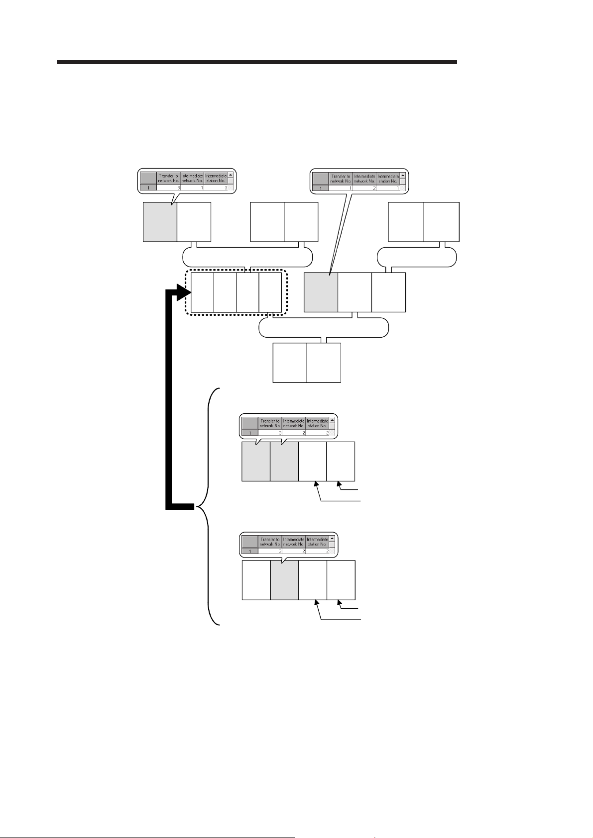
2 SYSTEM CONFIGURATION
(b) Setting routing parameters
If different control CPUs are set to relay stations, set the same routing
parameter to each of the control CPUs.
The following illustration shows a setting example where transient data are
transmitted from 1Mp1 to 3Ns2.
MELSEC-Q
QCPU
(Request
source)
1Mp1
QCPU 1Ns2
Network No.1
1Ns3 2Mp1QCPU QCPU
QCPU 2Ns3
1) When different control CPUs are set to relay stations, set the same routing parameter.
No.2No.1
2)
When the same control CPU is set to relay stations, set the routing parameter
only to the control CPU.
QCPU 2Ns2 3Mp1
Network No.2
1Ns3 2Mp1QCPU QCPU
Control CPU is QCPU No.2
Control CPU is QCPU No.1
QCPU
(Request
destination)
Network No.3
3Ns2
1Ns3 2Mp1QCPU QCPU
No.2No.1
Control CPU is QCPU No.2
Control CPU is QCPU No.2
2 - 13 2 - 13

2 SYSTEM CONFIGURATION
(4) Data cannot be transferred between data links with data link transmission
parameters if the control CPUs of the network modules on the multiple CPU
system are different.
(a) Transmission between data links possible
To transfer data to another network, use the CPU shared memory.
CPU No.1 is a
control CPU
MELSEC-Q
(b) Transmission between data links not possible
CPU No.1 is a
control CPU
CPU No.2 is a
control CPU
CPU
CPU
No.1
CPU
CPU
No.1
No.2
No.2
QJ71
BR11
QJ71
BR11
CPU
No.1
QJ71
BR11
CPU
No.2
QJ71
BR11
CPU
No.1
CPU
No.1
CPU
No.2
CPU
No.2
QJ71
BR11
QJ71
BR11
CPU
No.1
QJ71
BR11
CPU
No.2
QJ71
BR11
2 - 14 2 - 14

2 SYSTEM CONFIGURATION
(5) Precautions for executing a link dedicated instruction to a multiple CPU system
(Group specification, All stations)
If a WRITE/SWRITE, REQ, RRUN/RSTOP or RTMWR instruction is issued
under the following conditions (a), it may not be executed on some stations
depending on the system configuration (Control CPU setting) of the target
multiple CPU system. (Refer to (b).)
(a) Execution conditions
Target station CPU type ((S1)+3) setting
Target station No. ((S1)+5) setting
(b) Execution result
Target station
No. ((S1)+5)
setting
Group
specification
(81
to A0H) or
H
All stations
(FF
)
H
Target station CPU type
((S1)+3) setting
Multiple CPU system
No.1 (03E0
Multiple CPU system
No.2 (03E1
Multiple CPU system
No.3 (03E2
Multiple CPU system
No.4 (03E3
)
H
)
H
)
H
)
H
Target station’s
control CPU is No.1
O : The instruction is executed.
X : The instruction is not executed. Error completion is not identified on the execution source.
MELSEC-Q
Item Setting
Set the CPU type to any of the following.
• Multiple CPU system No.1 (03E0
• Multiple CPU system No.2 (03E1
• Multiple CPU system No.3 (03E2
• Multiple CPU system No.4 (03E3
Set the station No. of the target station to either of
the following.
• Group specification (81
• All stations (FF
Execution result
Target station’s
control CPU is No.2
Target station’s
control CPU is No.3
H
to A0H)
H
)
)
H
)
H
)
H
)
H
Target station’s
control CPU is No.4
2 - 15 2 - 15

2 SYSTEM CONFIGURATION
(6) When all of the following conditions from a) to d) are met, use a
MELSECNET/H module whose serial number (first five digits) is "10042" or later.
(a) A multiple CPU system containing a Built-in Ethernet port QCPU is
configured.
(b) To the Ethernet port of the Built-in Ethernet port QCPU, GX Developer or
GOT is connected.
(c) From GX Developer or GOT, access is made to another station through a
MELSECNET/H module controlled by another CPU.
(d) The access target on another station is an A/QnA series CPU module.
MELSEC-Q
2 - 16 2 - 16

2 SYSTEM CONFIGURATION
MELSEC-Q
2.2.3 List of functions for each CPU module
The available functions of the MELSECNET/H depend on the CPU module with which
a network module is mounted.
1)High Performance model QCPU, Process CPU
2)Basic model QCPU
3)Redundant CPU
4)Universal model QCPU
Function
Cyclic transmission function
MELSECNET/H Extended mode
Refresh parameter
Common parameter
Station inherent parameter
Inter-link data transfer function
Designation of I/O master station
Designation of reserved station
Low-speed cyclic transmission function
Redundant system function
Transient transmission function
Routing function
Group function
Message sending function using logical channel numbers
Link dedicated instruction
RAS function Section 3.2.2
Automatic return function
Control station shift function
Control station return control function
Loopback function
Station detach function
Transient transmission possible even in case of CPU error
Confirmation of transient transmission error detection time
Module diagnosis
Network test
Network diagnosis
Direct accessing of link device
Clock setting to a station on the network by GX Developer
Getting the interrupt sequence program started
Multiplexed transmission function
Simplified redundant setting of network
Increasing the number of send points by connecting multiple
modules of the same network number
*1: Up to 8 modules can be set.
*2: The low-speed LB/LW cannot be set because these models do not support the low-speed cyclic transmission function.
*3: The SREAD/SWRITE instruction’s read/write notice device (D3) becomes invalid. (The same operation as the
READ/WRITE instructions takes place.)
*4: It is available for the Basic model QCPU of function version B or later.
*5: Available for the Universal model QCPU whose serial No. (first 5 digits) is "09042" or later.
*6: For link dedicated instructions for the safety CPU, refer to Section 6.3.
*7: Basic model QCPU and safety CPU cannot execute a network test on a sequence program.
*8: Applicable to the Universal model QCPU excluding the Q00UJCPU, Q00UCPU, and Q01UCPU.
5)Safety CPU
CPU module
1) 2) 3) 4) 5)
*1
*2
*1
*3
*7
*5
*4
*5*8
*5*8
: Available, : Unavailable
Section 3.2.1
Section 5.1
*1
Section 5.7
*2
Section 5.3
Section 5.6
Section 7.2
Section 5.3.3
Section 5.3.4
Section 7.3
Section 7.10
Section 7.4
*1
Section 7.4.2
Section 7.4.3
Section 7.4.4
*3*6
Section 7.4.5
Section 3.2.2
Section 3.2.2
Section 3.2.2
Section 3.2.2
Section 3.2.2
Section 3.2.2
Section 3.2.2
Section 3.2.2
*7
Section 7.8
Section 8.1
Section 7.1
Section 7.4.6
Section 7.5
Section 7.6
Section 7.7
Section 7.9
Reference
section
2 - 17 2 - 17

2 SYSTEM CONFIGURATION
2.3 Checking Serial Number and Function Version
The serial number and function version of the network module can be checked on the
rating plate, front of the module, or system monitor window in GX Developer.
(1) Checking on the rating plate
The rating plate is located on the side of the network module.
MELSEC-Q
(2) Checking on the front of the module
The serial number and function version on the rating plate is printed on the front
(at the bottom) of the module.
The following network module is not included.
• QJ71LP21
110620000000000-D
Function version
Serial No.
2 - 18 2 - 18

2 SYSTEM CONFIGURATION
(3) Checking on the System Monitor screen (Product Information List)
To display the system monitor, select [Diagnostics] [System monitor]
Product Inf. List button of GX Developer.
Function version
Serial No.
MELSEC-Q
Product No.
(a) Production number display
Since the network module does not support the production number display,
POINT
The serial number displayed on the Product Information List screen of GX
Developer may differ from that on the rating plate or on the front of the module.
• The serial number on the rating plate or on the front of the module indicates
• The serial number displayed on the Product Information List screen indicates
"-" is displayed.
the management information of the product.
the functional information of the product.
The functional information of the product will be updated when a function is
added.
2 - 19 2 - 19
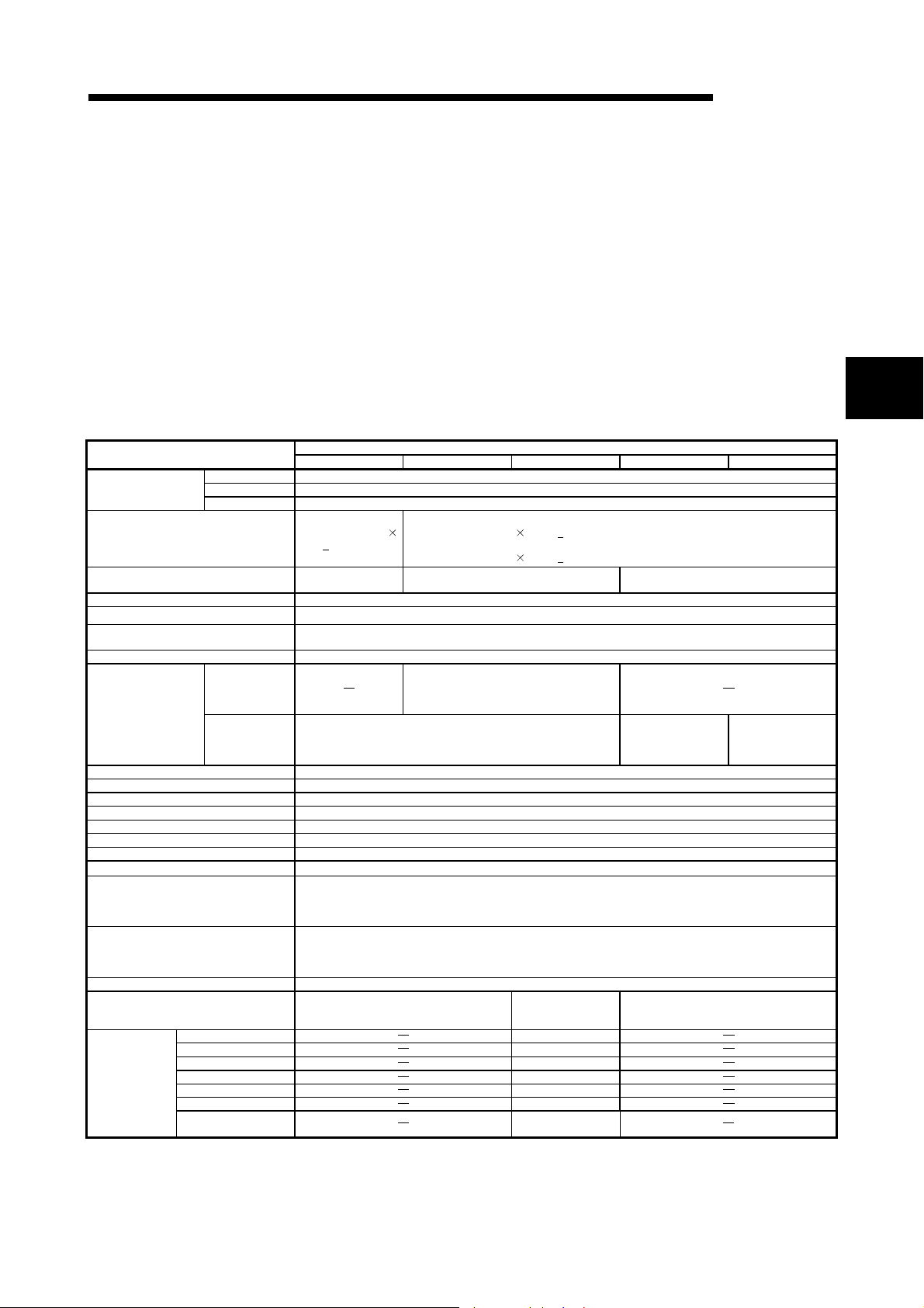
16
12
5
2
3 SPECIFICATIONS
MELSEC-Q
3 SPECIFICATIONS
This chapter explains the performance specifications and function specifications of the
network modules as well as the specifications of the send/receive processing time of
the link data.
For details of the general specifications, refer to the QCPU User's Manual (Hardware
Design, Maintenance and Inspection).
3.1 Performance Specifications
3.1.1 Performance specifications
Item
Maximum number of
link points per network
Maximum number of link points per station *1
Communication speed 10 Mbps
Number of stations per network Up to 64 stations (1 control station, 63 normal stations)
Connection cable Optical fiber cable (obtained by user)*2
Applicable connector
Overall distance 30km
Distance between
2
stations*
Maximum number of networks 239 (total including remote I/O networks)
Maximum number of groups 32 (9 in the MELSECNET/10 mode)
Transmission path format Duplex loop
Communication method Token ring
Synchronous method Frame synchronous
Encoding method NRZI code (Non Return to Zero Inverted)
Transmission format Conforms to HDLC (frame type)
Error control system
RAS function
Transient transmission
Special cyclic transmission function • Low-speed cyclic transmission function
Number of occupied I/O points
Voltage
Current
External Power
Supply
Size of terminal screw
Suitable crimp terminal
Suitable cable size
Tightening torque
Allowable momentary
power failure time
The following table lists the performance specifications of the network modules.
(1) Performance specifications of the optical loop system
LX/LY 8192 points
LB 16384 points (8192 points in the MELSECNET/10 mode)
LW 16384 points (8192 points in the MELSECNET/10 mode)
During 25Mbps
During 10Mbps
QJ71LP21 QJ71LP21-25 QJ71LP21S-25 QJ71LP21G QJ71LP21GE
• MELSECNET/H mode, MELSECNET/10 mode
{(LY + LB) / 8 + (2
LW)} 2000 bytes
Broad-band H-PCF optical cables: 1km
• Loopback function upon abnormal detection and cable breakage (optical loop system only)
• Diagnostic function of host link line check
• Prevention of system down by switching the control station
• Abnormal detection using link special relays and link special registers
• N:N communication (monitor, program upload/download, etc.)
• Various send/receive instructions from sequence programs (ZNRD/ZNWR, SEND/RECV, RECVS,
READ/WRITE, SREAD/SWRITE, REQ, RRUN/RSTOP, RTMRD/RTMWR.)
• Send function addressed to logical channel number of channel numbers 1 to 8
(I/O assignment: intelli.; 32 points)
{(LY + LB) / 8 + (2
• MELSECNET/H Extended mode
{(LY + LB) / 8 + (2
25 Mbps/10 Mbps
(Change with mode setting switch)
Two-core optical connector plug (obtained by user)
F06/F08 or equivalent (JIS C5975/5977 compliant)
SI optical cables: 200m
H-PCF optical cables: 400m
Broad-band H-PCF Optical Cables: 1km
SI optical cables: 500m
H-PCF optical cables: 1km
QSI optical cables: 1km
32 points
1ms (Level PS1)
QSI optical cables: 1km
Retries based on CRC (X
Optical loop system
LW)} 2000 bytes
LW)} 35840 bytes
+ X
+ X
48 (I/O assignment:
Empty; first 16, intelli.;
last 32)*3
20.4 to 31.2 V DC
0.20 A
M3 Screw
R1.25-3
0.3 to 1.25 mm
0.42 to 0.58 N·m
GI-50/125 optical
cables: 2km
+ 1) and timeover
(I/O assignment: intelli.; 32 points)
10 Mbps
GI-62.5/125 optical
32 points
3
cables: 2km
3 - 1 3 - 1

3 SPECIFICATIONS
External Power
Supply
Item
Noise immunity
QJ71LP21 QJ71LP21-25 QJ71LP21S-25 QJ71LP21G QJ71LP21GE
Internal current consumption (5VDC) 0.55 A
External dimensions
Weight 0.11 kg 0.20kg 0.11kg
1 The number of LY points of the stations set in the I/O master station is the sum total of the LY points for output to all stations within the block.
2 For old optical fiber cables (A-2P- ), L type differs from H type in the distance between stations. Refer to Section 4.6.1 for details.
3 Two slots are occupied.
Set the numeric value resulted from adding 10
3
The first empty 16 points can be set to "0" on the "I/O assignment" tab screen within the "Q Parameter" screen.
Example: Set 10
(Set 0
H
H
W
D
to the I/O No. of the slot where a module mounted as the "Starting I/O No." of the "Network parameter".
H
as the "Starting I/O No." when the module is mounted on slot 0.
H
as the "Starting I/O No." when 0 has been set to slot 0 on the " I/O assignment" tab screen.)
98mm 98mm
27.4mm
90mm 90mm
Optical loop system
By noise simulator of
500Vp-p noise
voltage,
1s noise width, and
25 to 60Hz noise
frequency
55.2mm
MELSEC-Q
98mm
27.4mm
90mm
3 - 2 3 - 2

3 SPECIFICATIONS
MELSEC-Q
Item
Maximum number of
link points per network
Maximum number of link points per station *1
Communication speed 10 Mbps
Number of stations per network Up to 32 stations (1 control station, 31 normal stations)
Connection cable Coaxial cable (obtained by user)
Applicable connector
Overall distance for one network
Maximum number of networks 239 (total including remote I/O networks)
Maximum number of groups 32 (9 in the MELSECNET/10 mode)
Transmission path format Single bus
Communication method Token bus
Synchronous method Frame synchronous
Encoding method Manchester code
Transmission format Conforms to HDLC (frame type)
Error control system
RAS function
Transient transmission
Special cyclic transmission function • Low-speed cyclic transmission function
Number of occupied I/O points 32 points (I/O assignment: intelli.; 32 points)
Internal current consumption (5V DC) 0.75A
H 98mm
External dimensions
Weight 0.11kg
1 The number of LY points of the stations set in the I/O master station is the sum total of the LY points for output to all stations within the block.
2 Some restrictions are applied to the cable length between stations depending on the number of stations connected. Refer to section 4.6.2 for details.
W 27.4mm
D 90mm
(2) Performance specifications of the coaxial bus system
Coaxial bus system
QJ71BR11
LX/LY 8192 points
LB 16384 points (8192 points in the MELSECNET/10 mode)
LW 16384 points (8192 points in the MELSECNET/10 mode)
• MELSECNET/H mode, MELSECNET/10 mode
{(LY + LB) / 8 + (2
• MELSECNET/H Extended mode
{(LY + LB) / 8 + (2 LW)} 35840 bytes
3C-2V 300m
5C-2V 500m 2
5C-FB 500m 2
Can be extended up to 2.5km with the use of a repeater unit (A6BR10, A6BR10-DC.)
• Diagnostic function of host link line check
• Prevention of system down by switching the control station
• Abnormal detection using link special relays and link special registers
• N:N communication (monitor, program upload/download, etc.)
• Various send/receive instructions from sequence programs (ZNRD/ZNWR, SEND/RECV, RECVS,
READ/WRITE, SREAD/SWRITE, REQ, RRUN/RSTOP, RTMRD/RTMWR.)
• Send function addressed to logical channel number of channel numbers 1 to 8
LW)} 2000 bytes
Connector plug for 3C-2V
Connector plug for 5C-2V
Connector plug for 5C-FB
Retries based on CRC (X
(obtained by user)
16
+ X12 + X5 + 1) and timeover
2
3 - 3 3 - 3
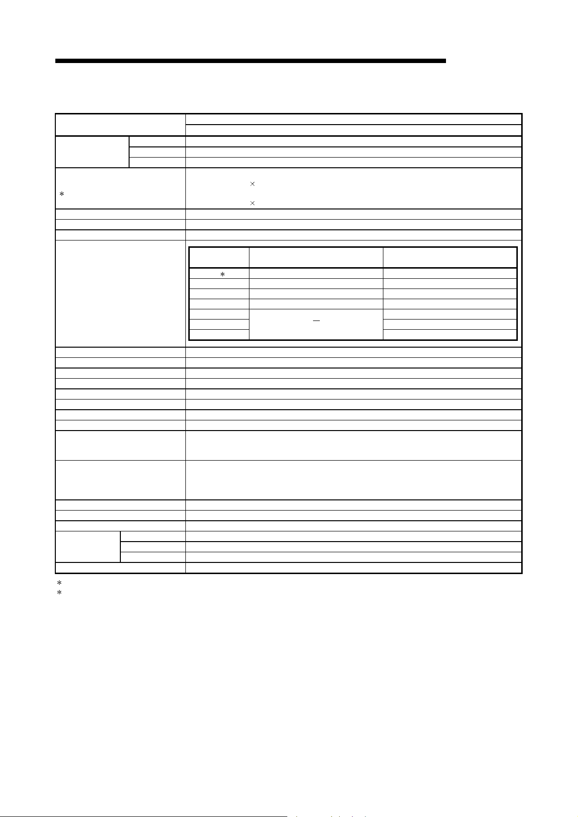
3 SPECIFICATIONS
MELSEC-Q
Item
Maximum number of
link points per network
Maximum number of link points per station
1
Communication speed 156kbps/312kbps/625kbps/1.25Mbps/2.5Mbps/5Mbps/10Mbps (Switched by network parameters)
Number of stations per network Up to 32 stations (1 control station, 31 normal stations)
Connection cable Shielded twisted pair cable or CC-Link Ver.1.10-compatible cable
(3) Performance specifications of the twisted bus system
Twisted bus system
QJ71NT11B
LX/LY 8192 points
LB 16384 points
LW 16384 points
• MELSECNET/H mode
{(LY + LB) / 8 + (2
• MELSECNET/H Extended mode
{(LY + LB) / 8 + (2
LW)} 2000 bytes
LW)} 35840 bytes
Communication
speed
156kbps 2 1200m 1200m
312kbps 600m 900m
Overall distance for one network
Maximum number of networks 239
Maximum number of groups 32
Transmission path format Bus (RS-485)
Communication method Token bus
Synchronous method Frame synchronous
Encoding method Manchester code
Transmission format Conforms to HDLC (frame type)
Error control system Retries based on CRC (X16 + X12 + X5 + 1) and timeover
RAS function
Transient transmission
Special cyclic transmission function • Low-speed cyclic transmission function
Number of occupied I/O points 32 points (I/O assignment: intelli.; 32 points)
Internal current consumption (5V DC) 0.6A
H 98mm
External dimensions
Weight 0.13kg
1 The number of LY points of the stations set in the I/O master station is the sum total of the LY points for output to all stations within the block.
2 This value is set as default of the communication speed.
W 27.4mm
D 90mm
625kbps 400m 600m
1.25Mbps 200m 400m
2.5Mbps
5Mbps 150m
10Mbps 100m
• Diagnostic function of host link line check
• Prevention of system down by switching the control station
• Abnormal detection using link special relays and link special registers
• N:N communication (monitor, program upload/download, etc.)
• Various send/receive instructions from sequence programs (ZNRD/ZNWR, SEND/RECV, RECVS,
READ/WRITE, SREAD/SWRITE, REQ, RRUN/RSTOP, RTMRD/RTMWR.)
• Send function addressed to logical channel number of channel numbers 1 to 8
Shielded twisted pair cable CC-Link Ver.1.10-compatible cable
(Not applicable)
200m
3 - 4 3 - 4
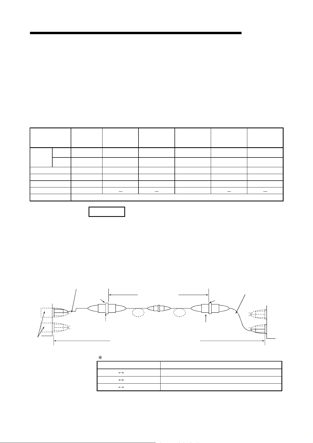
T
3 SPECIFICATIONS
MELSEC-Q
3.1.2 Optical fiber cable specifications
This section explains the specifications of the optical fiber cables used with the
MELSECNET/H optical loop system.
Details of the cable specifications must be checked for each cable used.
A technical skill and a special tool are needed when connecting an optical fiber cable
to an exclusive connector.
Optical fiber cables with connectors are available from Mitsubishi Electric System &
Service Co. Ltd. (Catalogs of the optical fiber cables are also available.)
Item
Distance
between
stations
Transmission loss 12 dB/km 6 dB/km 5 dB/km 5.5 dB/km 3 dB/km 3 dB/km
Core diameter 200 m 200 m 200 m 185 m 50 m 62.5 m
Clad diameter 220 m 250 m 250 m 230 m 125 m 125 m
Primary membrane 250 m
Applicable connector F06/F08 or equivalent (JIS C5975/5977 compliant)
10 Mbps 500m 1 km 1 km 1 km 2 km 2 km
25 Mbps 200m 400m 1 km 1 km Must not be used Must not be used
For cabling, consult your local Mitsubishi Electric System & Service representative.
SI (Multi-
particulate
glass)
H-PCF
(Plastic-clad)
Broad-band H-
PCF (Plastic-clad)
QSI (Quartz glass)
250 m
GI-50/125
(Quartz glass)
GI-62.5/125
(Quartz glass)
Conversion cable (1m) *1
QJ71LP21GE
SD
IN
RD
OUT
SD
RD
Connection loss: 1 dB (max.) Connection loss: 1 dB (max.)
Optical
module
REMARKS
The following types of optical fiber cables are available.
A type : Cable for connection inside control panel
B type : Cable for connection between control panels inside a building
C type : Cable for outdoor connection
DL type : Reinforced cable for outdoor connection
For other special-purpose cables such as flexible cables or heat-resistant cables,
contact Mitsubishi Electric System & Service Co., Ltd.
(1) Cable loss of GI-62.5/125 optical fiber cable
Adaptor
5.5 dB or less
Total cable loss = 7.5 dB or less
1: Conversion cable
Conversion Type Cable
CA type FC type AGE-1P-CA/FC1.5M-A
CA type ST type AGE-1P-CA/ST1.5M-A
CA type SMA type AGE-1P-CA/SMA1.5M-A
Purchased from: Mitsubishi Electric Europe GmbH
Conversion cable (1m)
Adaptor
SD
RD
SD
RD
IN
OU
3 - 5 3 - 5

3 SPECIFICATIONS
3.1.3 Coaxial cable specifications
The following table lists the specifications of the coaxial cables used for the coaxial bus
system.
Use the following high frequency coaxial cables:
• 3C-2V (JIS C 3501 compliant)
• 5C-2V (JIS C 3501 compliant)
• 5C-FB (JIS C 3502 compliant)
(1) Coaxial cable specifications
The following table indicates the specifications of the coaxial cable.
Select coaxial cables that meet the operating ambient temperature (0 to 55
shown in the general specifications of the programmable controller.
Item 3C-2V 5C-2V 5C-FB
MELSEC-Q
)
C
Structure
Cable diameter 5.4 mm (0.21 inches) 7.4 mm (0.29 inches) 7.7 mm (0.3 inches)
Minimum allowable bend radius 23 mm (0.91 inches) or more 30 mm (1.18 inches) or more 30 mm (1.18 inches) or more
Internal conductor diameter
Insulating material diameter
External conductor diameter
Applicable connector plug
0.5 mm (0.02 inches) (annealed
copper wire)
3.1 mm (0.12 inches)
(polyethylene)
3.8 mm (0.15 inches)
(single annealed copper wire
mesh)
3C-2V connector plug
The following connector plugs are
recommended:
• BNC-P-3-NiCAu
(Manufactured by DDK Ltd.)
• BCP-C3B
(Manufactured by Canare
Electric Co., Ltd.)
*1
*2
Internal
conductive
material
Insulating
material
0.8 mm (0.03 inches) (annealed
4.9 mm (0.19 inches)
5.6 mm (0.22 inches)
(single annealed copper wire
5C-2V connector plug
The following connector plugs are
recommended:
• BNC-P-5-NiCAu
(Manufactured by DDK Ltd.)
• BCP-C5B
(Manufactured by Canare
Electric Co., Ltd.)
External
conductor
copper wire)
(polyethylene)
mesh)
*1
*2
Outer sheath
1.05 mm (0.04 inches) (annealed
copper wire)
5.0 mm (0.19 inches)
(polyethylene)
5.7 mm (0.22 inches)
(aluminum foil tape and annealed
copper wire mesh)
5C-FB connector plug
BCP-C5FA*2 (manufactured by
Canare Electric Co., Ltd.) is
recommended.
1: This connector plug is a soldering-type connector plug.
2: This connector plug is a crimping-type connector plug.
REMARKS
To order or for inquiries regarding connector plugs and coaxial cables, contact your
local Mitsubishi representative.
3 - 6 3 - 6

r
3 SPECIFICATIONS
(2) Connecting the coaxial cable connectors
CAUTION
Correctly solder coaxial cable connectors. Incorrect soldering may result in
malfunction.
Components of the BNC connector
MELSEC-Q
The following section explains how to connect the BNC connector (the connector
plug for the coaxial cable) to the cable.
(a) Using a BNC connector manufactured by DDK Ltd.
The following explains how to connect the BNC-P-3-NiCAu or BNC-P-5NiCAu to the cable.
Structure of the BNC connector and coaxial cable
Nut Washer Gasket
Plug shell
Clamp Contact
How to connect the BNC connector and the coaxial cable
1) Cut the portion of the outer sheath of the coaxial cable as shown in the
Cut this portion of the outer sheath
figure below.
A
Cable A
3C-2V 15mm (0.59 inches)
5C-2V, 5C-2V-CCY 10mm (0.39 inches)
2) Fit the nut, washer, gasket, and clamp onto the coaxial cable, as
shown below, and then loosen the external conductor.
Clamp
Nut
Washer
Gasket
3) Cut the external conductor, insulating material and internal conductor
to the dimensions shown below. Note that the external conductor must
be cut to the same dimension as the tapered section of the clamp and
Internal conductor
smoothed down to the clamp.
Insulating material
C
B
Clamp
and external conducto
Cable B C
3C-2V 6mm
(0.24 inches)
5C-2V, 5C-2V-CCY 7mm
(0.28 inches)
3mm
(0.12 inches)
5mm
(0.20 inches)
3 - 7 3 - 7

3 SPECIFICATIONS
POINT
(1) Note the following precautions when soldering the internal conductor and
(2) Before connecting or disconnecting the coaxial connector, touch a grounded
MELSEC-Q
4) Solder the contact to the internal conductor.
Solder here
5) Insert the connector assembly shown in (4) into the plug shell and
screw the nut into the plug shell.
contact.
• Make sure that the solder does not bead up at the soldered section.
• Make sure there are no gaps between the connector and cable insulator or
they do not cut into each other.
• Perform soldering quickly so the insulation material does not become
deformed.
metal object to discharge the static electricity from the human body. Failure to
do so may result in a module malfunction.
3 - 8 3 - 8
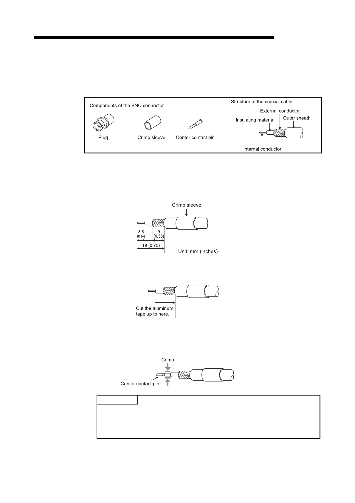
3 SPECIFICATIONS
MELSEC-Q
(b) Using a BNC connector manufactured by Canare Electric Co., Ltd.
The following explains how to connect the BCP-C3B, BCP-C5B, or BCPC5FA to the cable.
Structure of the BNC connector and coaxial cable
How to connect the BNC connector and the coaxial cable
1) Thread a coaxial cable through a crimping sleeve as shown in the
figure below.
When using a cable with aluminum tape, cut the tape as shown in the
figure below.
When cutting the tape, make a clean cut, without leaving any stray
pieces or loose strands. Failure to do so may cause a short circuit or
POINT
(1) Use a crimp tool specified for a BNC connector.
(2) Do not crimp the junction of the insulating material and the center contact pin.
(3) Horizontally insert the center contact pin into the insulating material and crimp
the pin. If the pin is on the tilt, straight it.
result in an improper crimp.
2) Insert a center contact pin into the internal conductor. Crimp the pin
using a crimp tool to seal the gap between the center contact pin and
the insulating material.
3 - 9 3 - 9
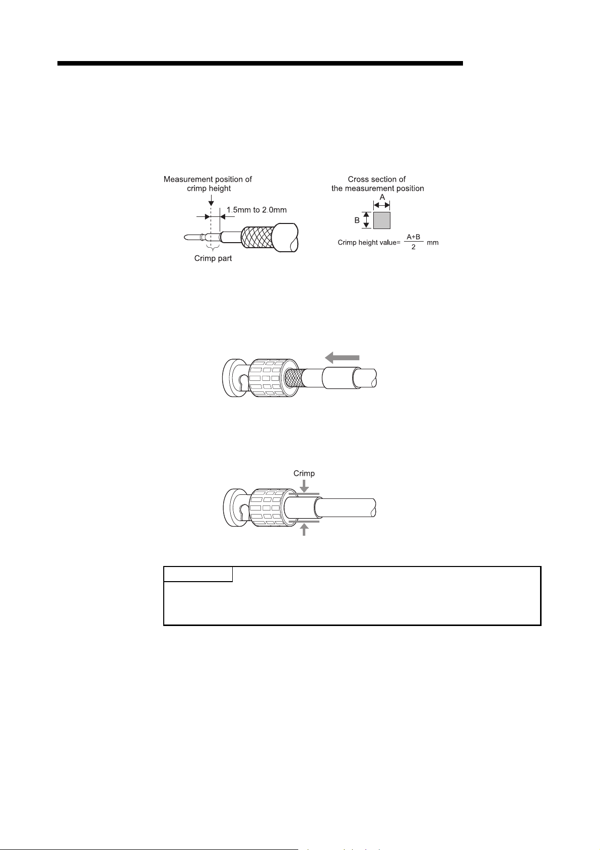
3 SPECIFICATIONS
MELSEC-Q
3) After the crimp, check the crimp height of the crimp part. When the
crimp height at the measurement position is between 1.4mm and
1.5mm, the pin is properly crimped.
If the crimp height is not between 1.4mm and 1.5mm, adjust the crimp
tool and crimp the center contact pin again.
4) Hold the root of the coaxial cable and fully insert the cable into a plug.
After inserting the cable, pull it lightly to check that the center contact
pin is fixed.
Move the crimp sleeve until it contacts with the plug.
5) Crimp the crimp sleeve using the crimp tool with attention paid to the
orientations of the crimp tool and connector.
Do not pull the cable when crimping the sleeve.
POINT
Before connecting or disconnecting the coaxial connector, touch a grounded metal
object to discharge the static electricity from the human body. Failure to do so may
result in a module malfunction.
3 - 10 3 - 10

3 SPECIFICATIONS
3.1.4 Shielded twisted pair cable specifications
The following shows the specifications of a shielded twisted pair cable used in the
twisted bus system.
Shielded twisted pair cables that satisfy the following specifications can also be used
even not introduced.
(1) Shielded twisted pair cable specifications
The following table lists the shielded twisted pair cable specifications.
Item KNPEV-SB 0.5SQ×1P 1
Cross section
MELSEC-Q
Cable Shielded twisted pair cable
Core 2-core
Conductor resistance (20C) 39.4 /km or less
Insulation resistance (20C) 10000M •km or more
Dielectric withstand voltage V-min 1000VAC 1 minute
Capacitance (1KHz) 70nF/km or less on average
Characteristic impedance (100KHz) 110±10
1: Applicable only when the communication speed is 1.25Mbps or less.
3 - 11 3 - 11
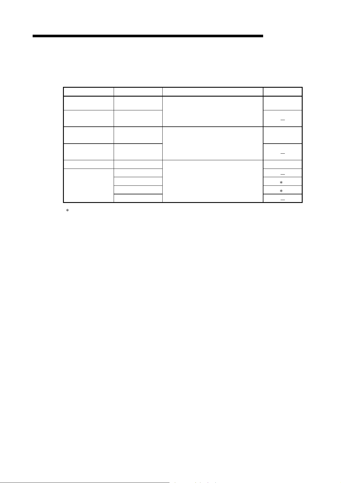
3 SPECIFICATIONS
(2) Connection of shielded twisted pair cables and terminals
Product name Model Manufacturer Remarks
This section explains connecting method of terminal and cable.
(a) Applicable solderless terminals and crimping tools
MELSEC-Q
Solderless terminal FA-VTC125T9
Tool dedicated for
solderless terminal
Solderless terminal TE0.5-10
Tool dedicated for
solderless terminal
Solderless terminal AI0.5-10WH
Tool dedicated for
solderless terminal
1: If a shielded or FG wire is crimped to a solderless terminal using the CRIMPFOX UD6-4 or CRIMPFOX
UD6-6, the wire may not be connected to the terminal block depending on the condition of cross section
of the solderless terminal after crimping.
FA-NH65A
NH-79
CRIMPFOX UD6
CRIMPFOX UD6-4 1
CRIMPFOX UD6-6 1
CRIMPFOX ZA3
For inquiries and orders, please contact
your local Mitsubishi Electric Engineering
Co., Ltd representative.
For inquiries and orders, please contact
your local NICHIFU TERMINAL MFG. Co.,
Ltd representative.
For inquiries and orders, please contact
your local Phoenix Contact representative.
0.3 to 1.65mm2
0.3 to 0.5mm2
0.5mm2
(b) Stripping the cable end
Use an appropriate tool to crimp the solderless terminal. (Refer to (a) in this
section)
For details of the crimping method, refer to the manuals for the solderless
terminal or crimping tool used.
In the example, a crimping tool "FA-VTC125T9" manufactured by
Mitsubishi is used.
1) Strip the cable jacket by 5.5mm to 6.5mm.
2) Place the terminal in the correct place (in the end) of the locator.
3) Insert the terminal until it reaches to the locator.
4) Insert the stripped cable into the terminal and crimp it.
3 - 12 3 - 12

3 SPECIFICATIONS
3.1.5 CC-Link Ver. 1.10-compatible cable specifications
(1) CC-Link Ver. 1.10-compatible cables for the twisted bus system
The following CC-Link Ver. 1.10-compatible cables can be used.
Product name Model Manufacturer
CC-Link Ver. 1.10-
compatible cable
FANC-110SBH Mitsubishi Electric System & Service Co., Ltd.
FA-CBL200PSBH Mitsubishi Electric Engineering Co., Ltd.
(2) Connection of a solderless terminal to the Version 1.10 compatible
CC-Link dedicated cable
For connection method of a solderless terminal and the cable, refer to Section
3.1.4 (2).
REMARKS
MELSEC-Q
For details, refer to the CC-Link cable wiring manual issued by CC-Link Partner
Association.
3 - 13 3 - 13

3 SPECIFICATIONS
3.2 Function Specifications
This section describes the functions of the MELSECNET/H.
The list of functions is shown below:
MELSEC-Q
3 - 14 3 - 14

3 SPECIFICATIONS
3.2.1 Cyclic transmission function (periodical communication)
The cyclic transmission function periodically allows data communication between
stations on the same network using the link devices (LB/LW/LX/LY).
In this manual, the devices on the network module side are prefixed by "L" so that
devices on the CPU module side (B/W/X/Y) and the link devices on the network
module side can be distinguished.
(1) Communication using LB/LW
By using this function, it is possible to write data to the link relay (LB) and link
register (LW) of the network module and to send the data to all the stations
connected within the same network.
(a) Available device range
Assign the link devices (LB/LW) in the network within the valid range for
writing data of each station on the common parameter LB/LW setting
screen of the control station. In addition, the actual device range may be set
with the refresh parameters or the station inherent parameters for each
station.
(b) Data communication
The link relay (LB) can send and receive the on/off information and the link
register (LW) can send and receive 16-bit data.
For example, in a network consisting of a control station and two normal
stations, when B0 of the control station turns on, the B0 contacts of the two
normal stations turn on. At this point, the station inherent parameters have
not been set.
Common parameter
LB/LW settings
MELSEC-Q
Control station 1M
B0
B100
B200
1FF
The LB/LW information of
other stations on the network is
transmitted to each station.
0
to
FF
100
to
200
to
2FF
P1
B(LB) B(LB)
Data
sending
area of
1M
1
P
Data
receiving
area of
1N
2
S
Data
receiving
area of
1N
S3
LB/LW data of 1M
LB/LW data of 1N
LB/LW data of 1M
LB/LW data of 1N
1
LB/LW data of 1N
P
3 LB/LW data of 1NS3
S
B(LB)
0
Data
receiving
to
area of
1M
P1
FF
Data
100
receiving
to
area of
1N
2
S
1FF
200
Data
sending
to
area of
1N
P3
2FF
Normal station 1N
Normal station 1NP2
P1
S2
S3
100
1FF
200
2FF
S
B0
B100
FF
0
to
to
to
2
Data
receiving
area of
1M
Data
sending
area of
1N
Data
receiving
area of
1N
S3
P1
2
S
B0
B100
B200
B200
3 - 15 3 - 15

3 SPECIFICATIONS
(2) Communication using LX/LY
MELSEC-Q
This function allows 1:1 communication between the I/O master station that
controls LX/LY and other stations (maximum of 63 stations in the optical loop
system and maximum of 31 stations in the coaxial bus system and twisted bus
system).
(a) Available device range
Data communication is performed using the input (X) and output (Y) after
the actual I/O of the host.
For the assignments of the link devices (LX/LY) in the network, the I/O
master station and the valid range for writing data for each station are set
on the common parameter LX/LY setting screens (two screens) of the
control station. The actually available device ranges can also be set for
each station with refresh parameters. Up to two stations in a network may
be set as the I/O master stations.
(b) Data communication
The link input (LX) can send/receive the input information of each station in
the block and the link output (LY) can send/receive the output information of
the I/O master station.
For example, in a network consisting of a control station and three normal
stations, the on/off status can be controlled using the input/output devices
between each station and the I/O master station in each block, as shown
below.
Block 1
I/O master station
Common
parameter
LX/LY settings
Control
station
1M
1
P
Normal
station
2
1N
S
1NS2
LY
Block 1
I/O master
station 1M
1
P
LY
LX
LYLX
31N
1N
S
LX
Normal
station
1N
4
S
4
S
Normal
Block 2
station
I/O master station
1N
3
S
Block 2
I/O master
station 1N
LY
LX LY
1NS2 1NS4
3
S
LX
3 - 16 3 - 16

3 SPECIFICATIONS
I/O master station
1M
P1
XY
0
to
Actual I/O
6FF
MELSEC-Q
The following figure shows an example of the LX/LY communication assignments
between the 1M
When the 1M
Also, when the 1N
X1200
P1 station (I/O master station) and the 1NS2 and 1NS3 stations.
P1 station turns on Y1000, X1000 of the 1NS2 station turns on.
S3 station turns on Y1000, X1200 of the 1MP1 station turns on.
1N
2
S
X
0
to
8FF
Y
Actual I/O
X1000
Y1000
X1000
X11FF
Y1000
toto
Y11FF
X1000
to to
X11FF
X1200
to to
X12FF Y12FF
Y1000
Y11FF
Y1200
Y1000
1N
3
S
X
0
to
7FF
X1000 Y1000
to to
X10FF Y10FF
Y
Actual I/O
POINT
1) Any station can be set as an I/O master station regardless of whether the
station is a control or normal station.
2) The range in which the X/Y signals are set for the LX/LY communication is the
device range starting from the end of the actual I/O of the host (X/Y1000 or
thereafter is recommended). Assign these device ranges so that they do not
overlap in the following situations:
• When using multiple network modules (CC-Link IE Controller Network, CC-
Link IE Field Network, MELSECNET/H, CC-Link, etc.)
• When setting two I/O master stations.
3 - 17 3 - 17

3 SPECIFICATIONS
3.2.2 RAS function
The RAS as in the RAS function stands for Reliability, Availability and Serviceability
and refers to the overall ease of use of the automated equipment.
(1) Automatic return function
1) The normal station No. 3 is disconnected
due to a data link error.
Control
station
(station
No. 1)
MELSEC-Q
When a station disconnected from a network due to a data link error recovers
from the error, the station is automatically reconnected to the network and
restarts data link.
2) The station No. 3 recovers to the normal
status and returns to the system.
Down
Sub-control
station
(station
No. 2)
Network No. 1 Network No. 1Return
Normal
station
(station
No. 3)
Control
station
(station
No. 1)
Sub-control
station
(station
No. 2)
Return
Normal
station
(station
No. 3)
Normal
station
(station
No. 6)
POINT
Normal
station
(station
No. 5)
Normal
station
(station
No. 4)
Normal
station
(station
No. 6)
Normal
station
(station
No. 5)
Normal
station
(station
No. 4)
There is a limit to the number of faulty stations that can return to the system within
one link scan. For details, refer to Section 5.4, "Supplementary Settings."
3 - 18 3 - 18

3 SPECIFICATIONS
(2) Control station switch function
1) When the control station goes down, the station
No. 2 becomes the sub-control station.
Down
Control
station
(station
No. 1)
MELSEC-Q
By using this function, if the control station (the station for which the common
parameters have been set) goes down, another normal station becomes the subcontrol station to continue the data link.
2) When the sub-control station No. 2 goes down,
the station No. 3 becomes the sub-control station.
Switch
Sub-control
station
(station
No. 2)
Network No. 1 Network No. 1
Normal
station
(station
No. 3)
Control
station
(station
No. 1)
Down
Sub-control
station
(station
No. 2)
Switch
Sub-control
station
(station
No. 3)
Normal
station
(station
No. 6)
Normal
station
(station
No. 5)
Normal
station
(station
No. 4)
Normal
station
(station
No. 6)
Normal
station
(station
No. 5)
Normal
station
(station
No. 4)
(a) When switching the control station, whether to continue the cyclic
transmission or not can be selected from sub-control station.
• Common parameter supplementary setting: "Data link by sub-control
station when control station is down." is available. (For more details, refer
to Section 5.4, "Supplementary Settings.")
Selection of function
1 Select
2 Do not select
Operation during control station switching
Cyclic transmission Transient transmission
: Continued, : Stopped
(b) When the control station is switched, the data link stops temporarily. During
the data link pause, data immediately before the stop is maintained.
(c) During the data link pause, all the stations except the host are treated as
faulty stations.
REMARKS
1) The control station does not switch even if the cyclic transmission of the control
station is stopped with GX Developer (Refer to Section 7.8).
2) Any of the normal stations whose cyclic transmission is stopped with GX
Developer can be a control station.
3 - 19 3 - 19
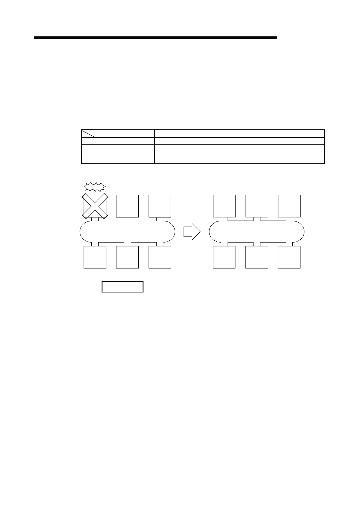
3 SPECIFICATIONS
(3) Control station return control function
Selection of function Control station after returning
1 Return as the control station The control station returns as the control station of the network.
2 Return as a normal station
1) When the control station is down, the station
No. 2 becomes the sub-control station.
Down
Control
station
(station
No. 1)
MELSEC-Q
The network stop time can be eliminated by correcting the errors that caused the
control station to go down and making it return to the network as a normal station.
How the control station returns to the network can be selected by the network
settings.
For details of the network setting, refer to Section 5.5, "Control Station Return
Setting."
For the control station return control function in the redundant system, refer to
Section 7.10.6.
The control station returns to the network again as a normal station, making the operating
sub-control station the new control station of the network. It can become the control station
again only by returning to the network when all other stations have gone down.
2) The network does not stop since the control station
returns to the network as a normal station.
Return
Sub-control
station
(station
No. 2)
Normal
station
(station
No. 3)
Control
station
(station
No. 1)
Sub-control
station
(station
No. 2)
Normal
station
(station
No. 3)
Return
Normal
station
(station
No. 6)
Normal
station
(station
No. 5)
Normal
station
(station
No. 4)
Normal
station
(station
No. 6)
Network No. 1 Network No. 1
Normal
station
(station
No. 5)
Normal
station
(station
No. 4)
REMARKS
• When "Return as the control station" is selected, the network stop time
becomes longer because the baton pass is stopped, but the common
parameters can be changed only by resetting the CPU of the control station.
• If "Return as a normal station" is selected, the network does not stop because
the control station returns to the network without stopping the baton pass.
However, it is necessary to reset the CPUs of all the stations after changing the
common parameters of the control station while the network is operating. If only
the CPU of the control station is reset, a parameter mismatch error is detected
in the control station and it is disconnected from the network.
3 - 20 3 - 20
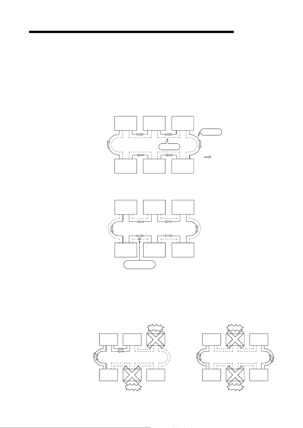
w
3 SPECIFICATIONS
(4) Loopback function (optical loop system)
MELSEC-Q
In the optical loop system, the transmission path is dual-structured. When an
error occurs in a transmission path, the faulty area is disconnected by switching
the transmission path from the forward loop to the reverse loop or from the
reverse loop to the forward loop, or performing a loopback. The transmission is
continued normally between the stations that are still able to perform data
communication.
(a) When normal
The data link is performed using the forward loop (or the reverse loop).
Control station
(station No. 1)
Normal station
(station No. 2)
Normal station
(station No. 6)
Reverse loop
Normal station
(station No. 3)
Normal station
(station No. 5)
Normal station
(station No. 4)
Forward loop
Data flo
(b) When abnormal
1) Error in the forward loop (reverse loop)
The data link continues using the reverse loop (forward loop).
Control station
(station No. 1)
Normal station
(station No. 6)
Normal station
(station No. 5)
Normal station
(station No. 2)
Cable disconnection
Normal station
(station No. 3)
Normal station
(station No. 4)
2) When some of the stations are down
The data link continues excluding the stations that are down.
When two or more stations are down, the data link cannot be
performed with the station located between the stations that are down.
However, when there are two or more stations between the stations
that are down, the normal station with younger station number
Control station
(station No. 1)
Normal station
(station No. 2)
Loopback
becomes the sub-control station to continue the data link.
Loopback
Normal station
(station No. 6)
Normal station
(station No. 3)
Down
Down
Normal station
(station No. 5)
Normal station
(station No. 4)
Communication
disabled
Control station
(station No. 1)
Normal station
(station No. 2)
Down
Normal station
(station No. 6)
Normal station
(station No. 3)
Down
Normal station
(station No. 5)
Normal station
(station No. 4)
Sub-control
station
3 - 21 3 - 21

3 SPECIFICATIONS
(c) Precautions in using the optical loop system
1) When the cable is inserted or removed, the line (forward loop/reverse
loop) may be switched, but the data link will be performed normally.
2) When the loopback is being executed due to a cable disconnection,
both the forward and reverse loops may be recognized as normal
depending on the condition of the cable disconnection.
Whether the forward/reverse loop is normal/abnormal is determined by
the status of "RD" (receive) of the loopback station.
(Example)
In the cases described below, the data link continue by dividing the network into
two loops: "1M
P1-1NS5-1NS6" and "1NS2-1NS3-1NS4."
<Loop containing 1MP1-1NS5-1NS6>
1M
1: Forward loop normal/reverse loop normal
P
1N
5: Forward loop normal/reverse loop normal
S
1N
6: Forward loop normal/reverse loop normal
S
<Loop containing 1N
1N
2: Forward loop "RD" abnormal/reverse loop normal
S
1N
3: Forward loop normal/reverse loop normal
S
1N
4: Forward loop normal/reverse loop "RD" abnormal
S
2-1NS3-1NS4>
S
An RD abnormal detection in the forward loop Loopback with the reverse loop
Sub-control station
MELSEC-Q
Forward loop
normal
Reverse loop
normal
Forward loop
abnormal
Reverse loop
abnormal
Control station
1MP1
Loopback
SD
RD
Forward
SD
Forward
Normal station Normal station Normal station
RD
SD
Forward
RD
Forward
Reverse SDReverse
Reverse RDReverse
1NS6 1NS5 1NS4
Normal station Normal station
1NS2 1NS3
Loopback
RD
Forward
Reverse SDReverse
SD
Forward
Reverse RDReverse
Loopback Loopback
RD
SD
Forward
Forward
SD
RD
RD
Forward
Reverse SDReverse
SD
Forward
Reverse RDReverse
RD
SD
SD
Forward
RD
Forward
An RD abnormal detection in the reverse loop Loopback with the forward loop
3 - 22 3 - 22

3 SPECIFICATIONS
REMARKS
If the network module has become faulty, a loopback may not be made depending
on the fault. In this case, the data link may become deactivated. Identify the faulty
network module in the following method.
(1) Check the LED indications (RUN LED off, ERR. LED on) of all network modules
(2) Turn off the power to all stations, then turn it on in order from the control station.
Replace any network module in which malfunction has been detected, and confirm
that the data link is properly recovered.
MELSEC-Q
for a faulty station.
In this process, check to which station of the network loopback is properly
executed.
Confirm in the Link information of the Network diagnostics (Host information)
screen that the control station and the normal station returned to the network is
displayed as loopback stations. (Refer to Section 8.1.1.)
3 - 23 3 - 23
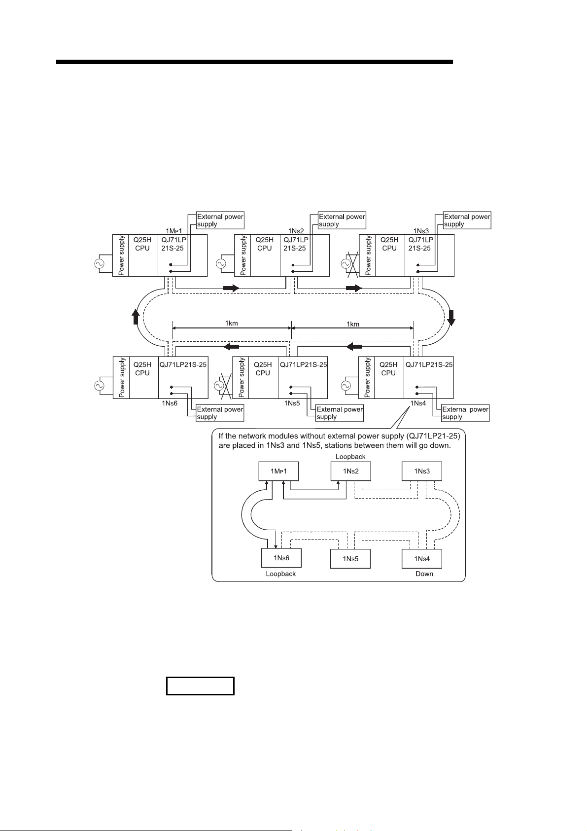
3 SPECIFICATIONS
(5) Prevention of station failure by using external power supply (Optical
MELSEC-Q
loop system)
Direct power supply (24 V DC) from outside to network modules will prevent the
loopback operation. Because of this, station(s) placed between faulty stations will
not go down when more than one station go down, (The QJ71LP21S-25 is the
network module where power can be supplied from outside.)
Even if the distance between normally operating stations (1Ns2 and 1Ns4, 1Ns4
and 1Ns6) is 1 km or more, normal data link will be available
(a) Precautions for operation
If the external power supply of the network module is powered on while the
CPU module power supply is off, the network module will not normally
operate.
Power on the CPU module and the external power supply then start system
operations.
REMARKS
Even if the CPU module on the control station is powered off, the control station will
not shift to a normal station because the network module operates normally.
3 - 24 3 - 24
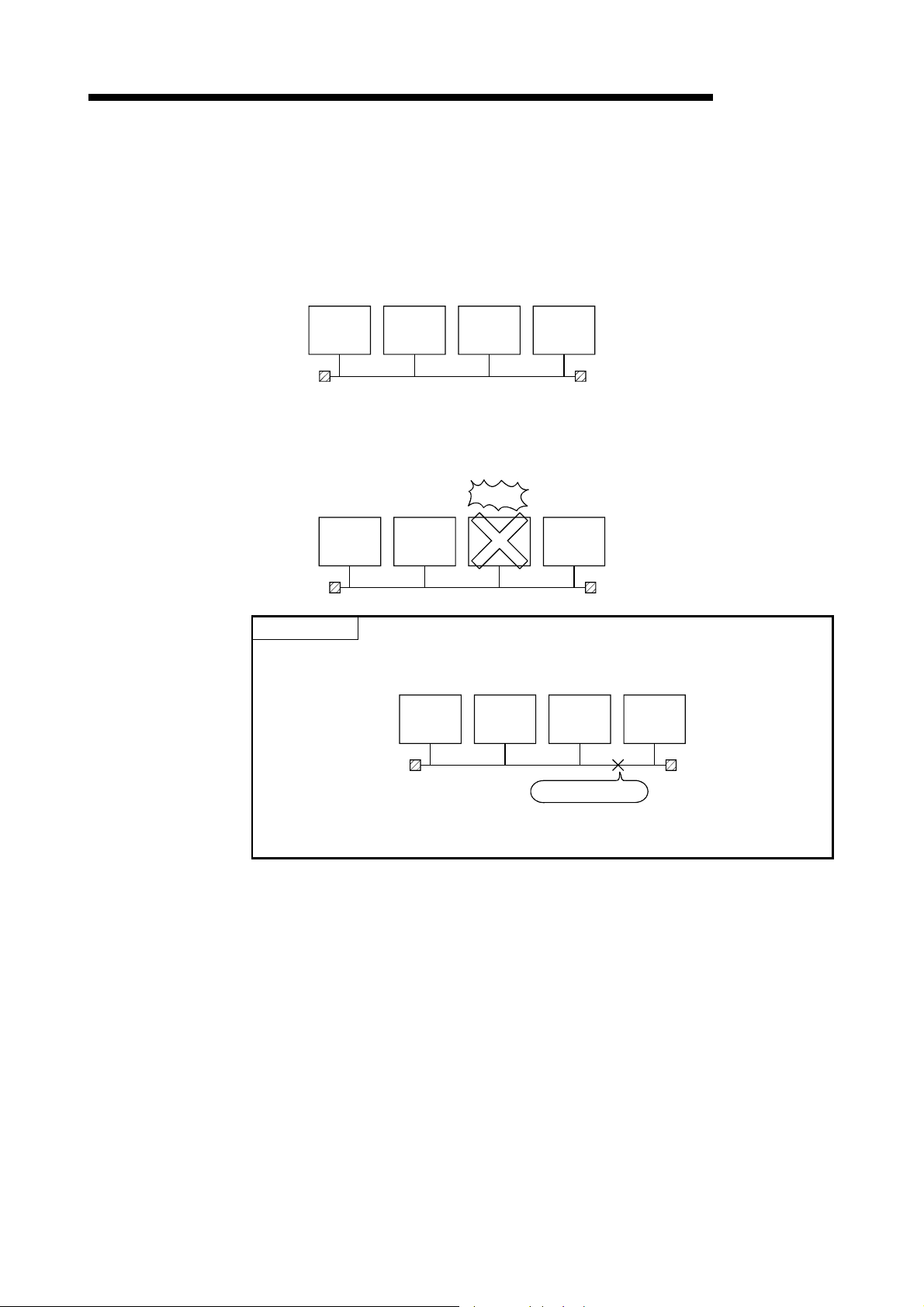
r
3 SPECIFICATIONS
(6) Station detach function (coaxial bus system and twisted bus
MELSEC-Q
system)
In the coaxial bus system and twisted bus system, even if the power to a
connected station is turned off, the data link continues between other stations
which are still able to perform data communication.
(a) When normal
Control station
(station No. 1)
Normal station
(statio n No. 2)
Normal station
(station No. 3)
Normal station
(station No. 4)
Terminating resistor
Terminating resisto
(b) When abnormal
The data link continues excluding the station that is down.
Down
Control station
(statio n No. 1)
Normal station
(statio n No. 2)
Normal station
(station No. 3)
Normal station
(station No. 4)
POINT
When a cable disconnection occurs, the data link cannot be performed because
there will be no terminating resistors.
Control station
(station No. 1)
Normal station
(station No. 2)
Normal station
(station No. 3)
Cable disconnection
Normal st ation
(station No. 4)
In addition, even if the cable is normal, the data link cannot be performed if a
terminating resistor is detached.
3 - 25 3 - 25

r
3 SPECIFICATIONS
(7) Transient transmission enabled even at CPU module error
MELSEC-Q
By using this function, the network module can continue the transient
transmission even if an error that stops the CPU module occurs while the system
is operating.
The description of the error of the corresponding station can be checked from
other stations using GX Developer.
OPERATION ERROR
QCPU
Power supply
QCPU
Power supply
QJ71
LP21
QJ71
LP21
Power supply
QCPU
Power supply
QCPU
QJ71
LP21
QJ71
LP21
GX Develope
The following table lists the operations of the cyclic and transient transmissions
for each CPU module status.
CPU module status
Battery error
Annunciator error ON, etc.
(Continue error)
Parameter error
Instruction code error, etc.
(Stop error)
CPU reset, etc.
(MAIN CPU down)
Rank
Minor error Continued Enabled
Medium error Stopped Enabled
Major error Stopped Disabled
Cyclic transmission Transient transmission
1
1 When the CPU module on the target station is an ACPU, a communication
error occurs.
In case of the QCPU and QnACPU, a CC-Link IE Controller Network, CCLink IE Field Network, MELSECNET/H, MELSECNET/10 error is returned.
3 - 26 3 - 26
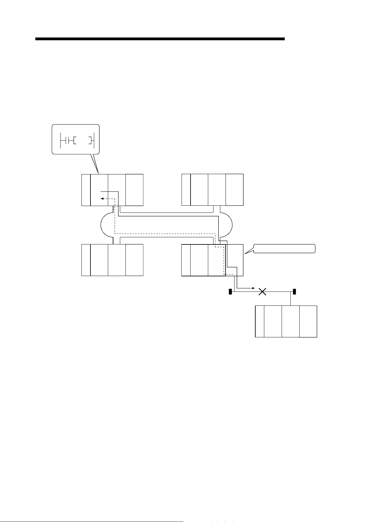
3 SPECIFICATIONS
(8) Checking the transient transmission abnormal detection time
SEND
Request source
Q25H
QJ71
CPU
LP21
MELSEC-Q
By using this function, the "Time," "Abnormal detection network number," and
"Abnormal detection station number" can be checked when a transient
transmission (SEND, READ, SREAD, WRITE, SWRITE, REQ and other
instructions) ends abnormally.
Logs such as time logs can be used to identify the network problems.
For details of these instructions, refer to Section 7.4.5.
QJ71
Q25H
LP21
CPU
Power supply
Q25H
CPU
Power supply
QJ71
LP21
Power supply
Q25H
CPU
Power supply
QJ71
LP21
QJ71
BR11
Abnormal detection station
Q25H
QJ71
CPU
BR11
Power supply
Request destination
3 - 27 3 - 27

3 SPECIFICATIONS
(9) Diagnostic function
The diagnostic function is used to check the network's line status and the module
setting status.
The diagnostic function consists mainly of following two types of tests:
• Offline tests
• Online tests
POINT
Execute the online tests when the network module is communicating (T.PASS LED
is on). An error occurs if any of the online tests is executed from a station that has
been disconnected from the data link.
Item Description
Checks hardware including the send/receive circuits and the
Self-loopback test
Internal self-loopback test
Hardware test Checks hardware inside the network module.
Station-to-station test Checks a line between two stations.
Forward loop/reverse
loop test
Item Description
Loop test Checks the line status.
Setup confirmation test
Station order check test
Communication test
1: The setup confirmation test cannot be executed in the twisted bus system.
cables of the transmission system of an individual network
module.
Checks hardware including the send/receive circuits of the
transmission system of an individual network module.
Checks the wiring status of the forward and reverse loops in
the status in which all the stations are connected.
Checks for duplicate control stations and
station numbers.
Checks the order of stations connected
in the directions of the forward and
reverse loop.
Checks whether or not the transient
transmission can be performed normally.
It also checks the routing parameter
settings.
1) Offline tests
The network module's hardware and the data link cable wiring can be
checked at the system startup by setting the network module or GX
Developer to the test mode.
2) Online tests
The status of a line and other items can be easily checked with GX
Developer.
If an error occurs while the system is in operation, the diagnostics
listed below can be executed while remaining in the online status.
Optical loop
system
Optical loop
system
Coaxial/twisted
bus system
1
MELSEC-Q
Coaxial/twisted
bus system
Data link status
(cyclic transmission or
transient transmission)
Pause Section 4.8.1
Pause Section 4.8.2
Pause Section 4.8.3
Continue Section 4.8.4
Reference
Section 4.5.1
Section 4.5.2
Section 4.5.3
Section 4.7.1
Section 4.7.2
Reference
section
section
3 - 28 3 - 28

3 SPECIFICATIONS
3.3 Specifications of the Link Data Sending/Receiving Processing Time
This section explains the link data sending/receiving processing time and how to
calculate the data link transmission delay time in the MELSECNET/H network system.
3.3.1 Link data sending/receiving processing
(1) Overview of the sending/receiving processing
In the cyclic transmission, communication is performed using the LB/LW/LX/LY
devices of the network module.
This section explains the case when the link relay (B) is used on the CPU module
side.
1) B0 on the sending station turns on.
2) By a link refresh, the B0 information is stored in the refresh data
storage area (LB) of the network module.
3) The B0 information in the refresh data storage area (LB) is stored in
the link data storage area (LB).
4) By a link scan, the B0 information in the link data storage area (LB) is
stored in the link data storage area (LB) of the network module on the
receiving station.
5) The B0 information in the link data storage area (LB) is stored in the
refresh data storage area (LB).
6) By a link refresh, the B0 information is stored in the device memory
storage area (B) of the CPU module.
1)
7) B0 on the receiving station turns on.
MELSEC-Q
7)
X0
QCPU
Sequence scan
Device
memory
storage ar ea
B0
Sending station Receiving station
Network module
B
2)
Link refresh
D
N
E
1
LB
Refresh data
storage area
2 3 23
3)
LB
4)
Link scan
Link data
storage area
Network module
LB
Link data
storage area
5)
LB
Refresh data
storage area
B0
6)
Link refresh
1
Y10
QCPU
B
Sequence scan
Device
memory
storage area
E
N
D
1: Sets the values with the refresh parameters.
2: Sets the values with the station inherent parameters. (If the settings are not made, the
values of the common parameters are stored as is.)
3: Sets the values with the common parameters of the control station.
3 - 29 3 - 29

3 SPECIFICATIONS
(2) Link scan and link refresh
Sequence scan
MELSEC-Q
The link scan is executed "asynchronous" with the sequence scan of the CPU
module.
The link refresh is executed by the "END processing" of the CPU module.
0
END
Link refresh Link refresh Link refresh
0
END
0
END
0
END
Link scan
POINT
When the CPU module is powered on or reset, even if latched device (listed in
"CPU side device" in the table below) data is cleared to "0" using a sequence
program, the latched data may be output depending on the timing of link scan and
link refresh.
For how to prevent outputting latched device data, refer to "Method for disabling
output" in the table below.
CPU side device Method for disabling output
Latch relay (L) Clear the device data to "0" using an
File register (R, ZR)
Extended data register (D)
initial device value
Delete all latch range settings.
( 1)
.
(Universal model QCPU only)
Extended link register (W)
(Universal model QCPU only)
Device within latch range
1: For initial device value setting, refer to the user’s manual (Function
Explanation, Program Fundamentals) for the CPU module used.
3 - 30 3 - 30

3 SPECIFICATIONS
(3) Link data when a communication error station or communication
MELSEC-Q
stop station occurs on the network
When a communication error or communication stop station occur on the
network during the data link, the receive data from those stations immediately
before the error occurrence is retained.
(A "communication stop station" refers to a station whose cyclic transmission has
been stopped by a peripheral device.)
(a) The receive data from a communication error station or communication
stop station is retained by a normally communicating station.
(b) The receive data from other station is retained by a communication stop
station.
(Example)
When a communication error has occurred to 1N
Communication
1MP1 1NS2
Cable disconnection
error station
S2 due to cable disconnection
1NS3
Cable disconnection
Link data status after disconnection
1MP11N
Link data Link data Link data
1MP1
1N
2
S
1N
3
S
1NS2
1MP1
1NS2
1N
3
S
· · · · · · Area where the link data is retained
1MP1
1N
1N
3
S
2
S
3
S
3 - 31 3 - 31

3 SPECIFICATIONS
(4) SB/SW when a communication error station/communication stop
MELSEC-Q
station occurs on the network
The status of whether there are any communication error/communication stop
stations on the network can be checked with the link special relay/link special
register (SB/SW).
Use them as interlocks for programs.
For interlock program examples, refer to Section 6.1.2.
Link special relays and registers
Link special
relay/link
special
register
SB0020
SB0047 Shows the baton pass execution status of the host.
SB0049 Shows the cyclic transmission status of the host. Normal Abnormal
SB0070
SW0070 to
0073
SB0074
SW0074 to
0077
Shows the communication status between the
network module and CPU module.
Shows the baton pass execution status of all
stations (including the host). However, it only shows
the status for the number of stations set with
parameters.
Shows the baton pass execution status of each
station.
Each bit corresponds to the status of each station.
Shows the cyclic transmission status of all stations
(including the host). However, it only shows the
status for the number of stations set with
parameters.
Shows the cyclic transmission status of each station.
Each bit corresponds to the status of each station.
Description
Signal status
Off On
Normal Abnormal
The baton
pass is being
executed
The baton
pass is being
executed on
all stations
The baton
pass is being
executed
All stations
normal
Normal Abnormal
SB007A
The baton
pass is
stopped
Occurrence
of
communicati-
on stop
station
The baton
pass is
stopped
Occurrence
of abnormal
station
SB007A,
007B
SW01FC to
SW01FF
*1: Signals for the stations in other than a redundant system are off.
Shows the low-speed cyclic transmission status.
The transmission completion is indicated by the
on/off status of either bit SB007A or 007B.
Indicates the redundant system status (control
system/standby system) of each station. Each bit
corresponds to the status of each station.
SB007B
Low-speed cyclic interval
Control
system
Standby
*1
system
3 - 32 3 - 32

3 SPECIFICATIONS
3.3.2 How to calculate the transmission delay time
(1) Transmission delay time in the same network
(a) Cyclic transmission (LB/LW/LX/LY periodical communication)
The transmission delay time in the B/W/Y communication is obtained by the
equation below using the following variables:
• Scan time for the sending and receiving stations (except link refresh time)
• Link refresh time
• Link scan time
• Tracking time
• Scan time delay due to tracking transfer
1) When a non-redundant CPU receives data
T
(MAX : T
2) When a redundant CPU receives data
TD1 = ST + T + (LS 0.5) + (SR + R + Ts) 1.5 [ms]
(MAX : T
POINT
(1) For the transmission delay time in the B/W/Y communication (TD1), use the
(2) When the "Block send/receive data assurance per station" boxes is checked,
(3) In the MELSECNET/H Extended mode, the "Block send/receive data assurance
[Transmission delay time (TD1) in B/W/Y communication]
= ST +
D1
+ (LS 0.5) + (SR +
T
= ST +
D1
= ST +
D1
T : Scan time of the sending station (except link refresh time)
S
R : Scan time of the receiving station (except link refresh time)
S
T : Link refresh time of the sending station 1
R : Link refresh time of the receiving station 1
+ (LS 1) + (SR +
T
+ (LS 1) + (SR +
T
LS : Link scan time
Ts : Scan time delay due to tracking transfer
1: Total of installed network modules
2: For the scan time delay due to tracking transfer, refer to the
QnPRHCPU User's Manual (Redundant System).
The equation above assumes the following conditions:
• There is no faulty station.
• The transient transmission is not executed.
equation for the "MAX" if the worst conditions coincide because the scan of the
sequence program and the link scan are asynchronous.
add the following delay time to the transmission delay time (T
• In the case of S
Normal : Add "+ 0.5
MAX : Add "+ 1.0
• In the case of S
Normal : Add "+ 0.5
MAX : Add "+ 1.0
T >LS
(ST + T)"
(ST + T)"
T <LS
LS"
LS"
per station" boxes are preset by default. Therefore, add any of the values
shown in (2) above to the transmission delay time (T
) 1.5 [ms]
R
R
R
) 2)
+ Ts) 2)
2
D1).
MELSEC-Q
D1).
3 - 33 3 - 33

3 SPECIFICATIONS
MELSEC-Q
(b) Communication with the SEND/RECV/RECVS/ZNRD/ZNWR instruction
The transmission delay time in communication with the SEND, RECV,
RECVS, ZNRD, or ZNWR instruction depends on the system of the
sending and receiving stations, as shown below.
Receiving station
Sending station
Non-redundant system Expression of 1)
Redundant system
Non-redundant system
Expression of 2)
(Note that the TsR value
is "0.")
Redundant system
(control system CPU)
Expression of 2)
(Note that the TsT value
is "0.")
Expression of 2)
The transmission delay time can be calculated using the following:
• Scan time for the sending and receiving stations (except link refresh time)
• Link refresh time
• Link scan time
• Scan time delay due to tracking transfer
[Transmission delay time in SEND, RECV, RECVS, ZNRD,
or ZNWR instruction communication]
1) TD2 = (ST + T + SR + R) 2 + (LS 4) + LSU [ms]
(MAX : T
2) T
= (S
D3
(MAX : T
= (ST + T + SR + R) 2 + (LS 6) + LSU)
D2
+
+ Ts
T
T
= (ST +T + TsT + SR + R TsR) 2 + (LS 6)+LSU)
D3
S
T : Scan time of the sending station (except link refresh time)
S
R : Scan time of the receiving station (except link refresh time)
T : Link refresh time of the sending station 2
R : Link refresh time of the receiving station 2
Ts
T : Scan time delay due to tracking transfer on the sending side 3
Ts
R : Scan time delay due to tracking transfer on the receiving side 3
T +SR
+
+TsR) 2+(LS 4) + LS
R
U
[ms]
LS : Link scan time
1
LS
(Number of simultaneous transient requests)
U
(Maximum number of transient times)
– 1
(LS 2)
Number of simultaneous transient requests:
The total number of times transient requests that are made during one link
scan from a station on the same network.
Maximum number of transients:
The maximum number of transients within one link scan set in the
supplementary settings of the common parameters.
1: The fraction is rounded up to the nearest whole number.
2: Total of installed network modules
3: For the scan time delay due to tracking transfer, refer to the
QnPRHCPU User's Manual (Redundant System).
3 - 34 3 - 34

3 SPECIFICATIONS
REMARKS
When executing transient transmissions from multiple stations at the same time, the
execution time of the instruction may be shortened by increasing the setting value
for the maximum number of transient requests in one link scan.
For instance, when there are seven stations that execute an instruction, the time for
"LS
requests from the default value of two to seven or larger with the transient setting in
the supplementary settings of the common parameters of GX Developer.
Note, however, that the scan time of the CPU module increases by that time amount.
(c) READ, WRITE, REQ, RRUN, RSTOP, RTMRD, or RTMWR instruction
communication
The transmission delay time in communication with the READ, WRITE, REQ,
RRUN, RSTOP, RTMRD, or RTMWR instruction depends on the system of the
Receiving
station
Sending
station
Non-redundant
system
Redundant system Expression of 2)
Non-redundant
Expression of 1) Expression of 2)
(Note that the Ts
value is "0.")
sending and receiving stations.
system
The transmission delay time in instruction communication can be calculated from
the following:
• Scan time of the sending and receiving stations (except link refresh time)
• Link refresh time
• Link scan time
• Scan time delay due to tracking transfer
[Transmission delay time in READ/WRITE/REQ/RRUN/RSTOP/
RTMRD/RTMWR instruction communication]
1) T
D4
(MAX : T
2) TD5 = (S
(MAX : T
3) TD6 = (S
(MAX : T
MELSEC-Q
4" may be shortened by changing the setting value of the maximum transient
Redundant system
Host system Other system
Access to control
system CPU
(Note that the Ts
value is "0.")
Expression of 2) Expression of 2)
R
= (ST +
+ SR +
T
= (ST +
D4
+
+ Ts
T
T
= (ST +
D5
+ T + Ts
T
= (ST +T + TsT + SR + R TsR) 2 (LS 6) + 6 + LSU)
D6
Access to standby
system CPU
Expression of 2)
T
(Note that the
values of Ts
and α
(However, the
values of S
α
R are "0.")
) 2 + (LS 4) + LSU [ms]
R
+ SR +
T
T +SR
+ TsT + SR +
T
T +SR
+
R
+ R +TsR) 2 (LS 4) + 3 + LSU [ms]
T, SR,
R are "0.")
R, and
) 2 + (LS 6) + LSU)
R
+TsR) 2 (LS 4) + LSU [ms]
R
Access to standby
system CPU via
control system
Expression of 3)
(Note that the Ts
value is "0.")
Expression of 3) Expression of 3)
Ts
) 2 + (LS 6) + LSU)
R
Access to control
system CPU via
standby system
Expression of 3)
T
(Note that the
values of Ts
and α
(Note that the
values of S
α
R are "0.")
T, SR,
R are "0.")
R, and
(To next page)
3 - 35 3 - 35
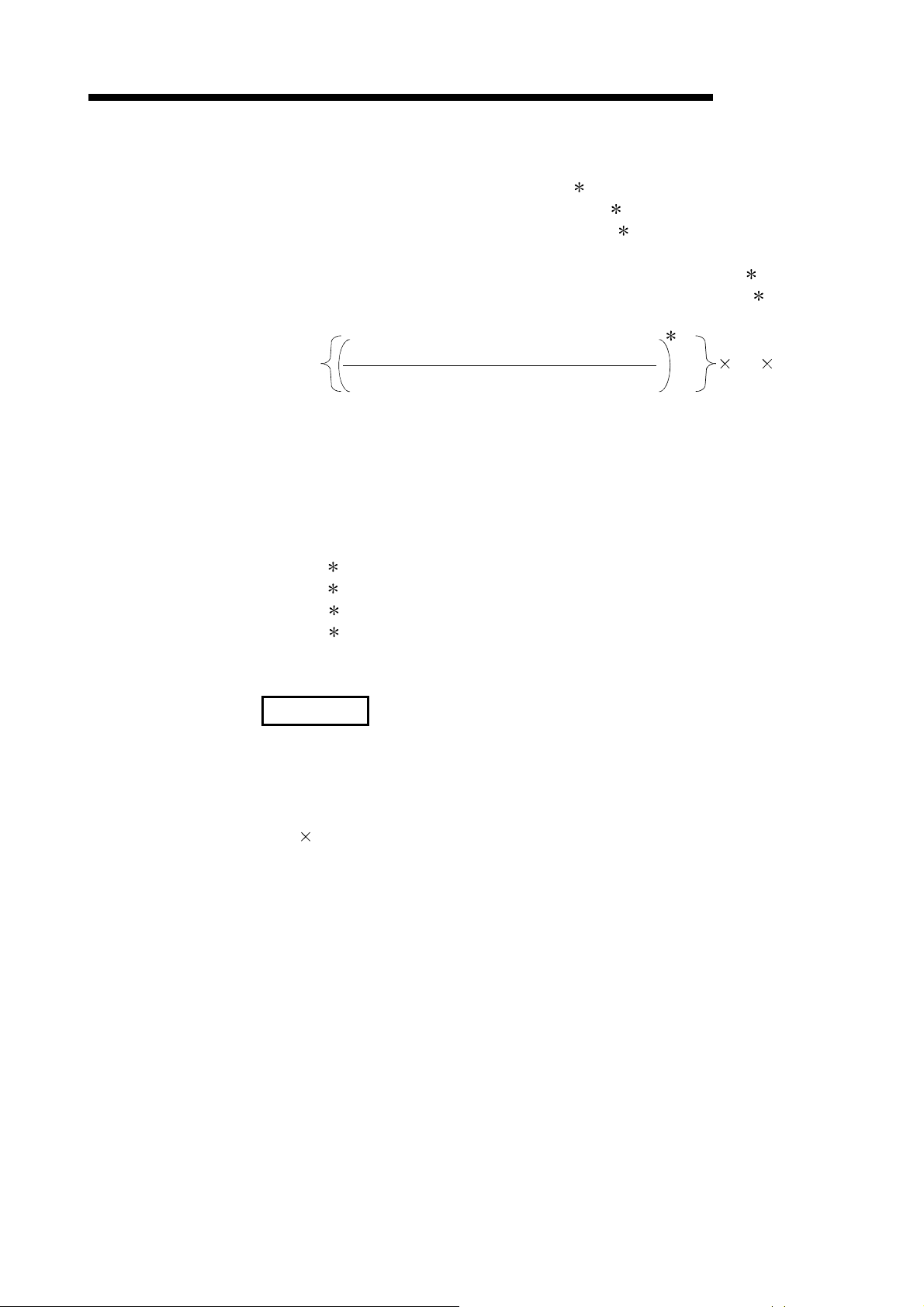
3 SPECIFICATIONS
MELSEC-Q
S
T : Scan time of the sending station (except link refresh time)
S
R : Scan time of the receiving station 1 (except link refresh time)
T : Link refresh time of the sending station 2
R : Link refresh time of the receiving station 2
LS : Link scan time
Ts
T : Scan time delay due to tracking transfer on the sending side 4
Ts
R : Scan time delay due to tracking transfer on the receiving side 4
3
LS
(Number of simultaneous transient requests)
U
(Maximum number of transient times)
– 1
(LS 2)
Number of simultaneous transient requests:
The total number of times transient requests that are made during one link
scan from a station on the same network.
Maximum number of transients:
The maximum number of transients within one link scan set in the
supplementary settings of the common parameters.
1: For the redundant system, it is a scan time of the control system CPU.
2: Total time for the installed network modules.
3: The fraction is rounded up to the nearest whole number.
4: For the scan time delay due to tracking transfer, refer to the
QnPRHCPU User's Manual (Redundant System).
REMARKS
When executing transient transmissions from multiple stations at the same time, the
execution time of the instruction may be shortened by increasing the setting value
for the maximum number of transient requests in one link scan.
For instance, when 7 stations are supposed to execute an instruction, the time for
"LS
4" may be shortened by changing the setting value of the maximum transient
requests from the default value of 2 to 7 or larger in the transient setting in
supplementary settings of Common parameters from GX Developer.
Note, however, that the scan time of the CPU module increases by that time amount.
3 - 36 3 - 36
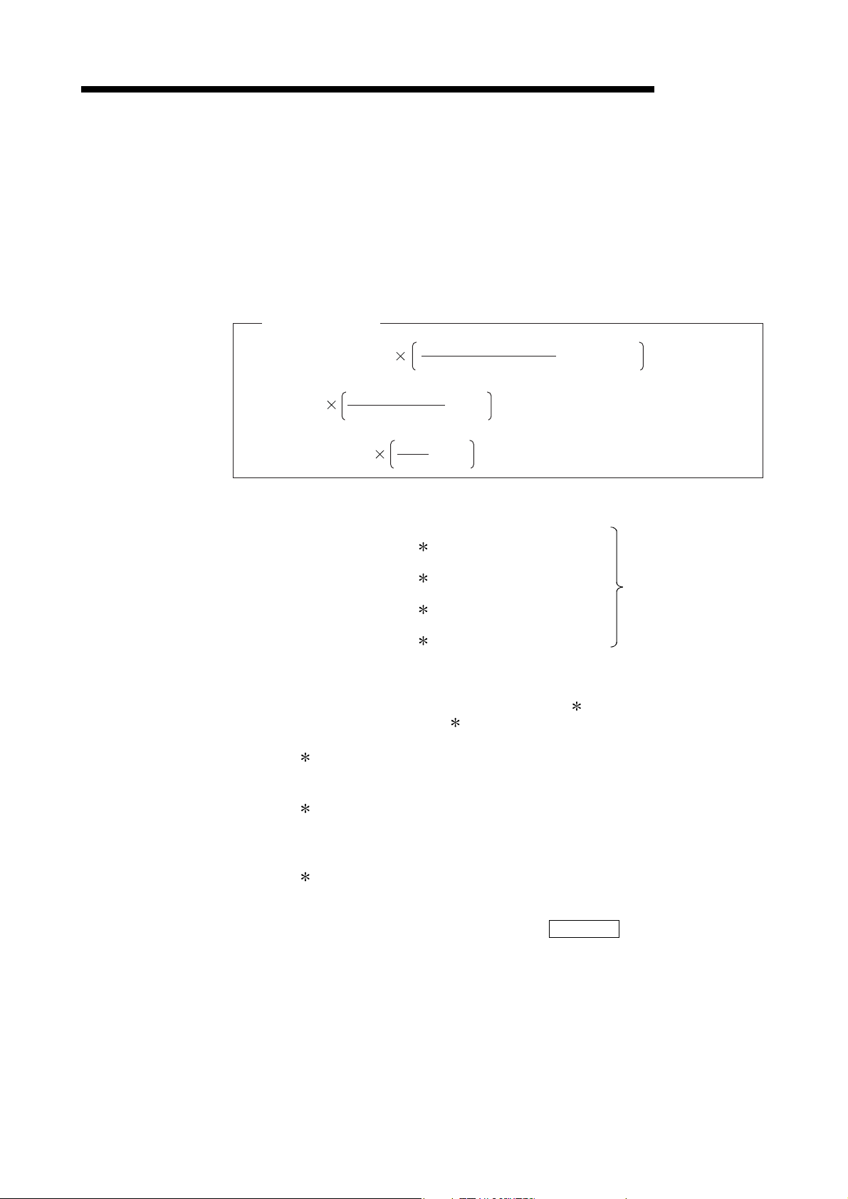
X
Y
3 SPECIFICATIONS
MELSEC-Q
(d) Link refresh time
1) Basic model QCPU, High Performance model QCPU, Process CPU,
Redundant CPU, Universal model QCPU
The link refresh time (the time delay of the END processing time in the
CPU module) is obtained by the equation below using the following
variables:
• Number of assignment points of the link device
• Transfer to the file registers (R, ZR), extended data register (D), and
extended link register (W) on the memory card
• Inter-link data transfer
[Link refresh time]
α
T
, αR = KM1 + KM2 + LW + SW
αE = KM3
LB + LX + LY
αL = KM4 + KM5
T : Link refresh time (sending station)
R : Link refresh time (receiving station)
LB + LX + LY + SB
16
LB
16
+ LW
+ LW
16
[ms]
[ms]
+ α
E
+ αL [ms]
LB : Total points of link relays (LB) refreshed by the
corresponding station
1
LW : Total points of link registers (LW) refreshed by the
corresponding station
: Total points of link inputs (LX) refreshed by the
L
corresponding station
: Total points of link outputs (LY) refreshed by the
L
corresponding station
1
1
1
Refer to Section
3.3.3.
SB : Number of points of the link special relay (SB)
SW : Number of points of the link special register (SW)
: Transfer time of the file registers (R, ZR), extended data register (D), and
E
extended link register (W) on the memory card
: Inter-link data transfer time
L
3
2
KM1, KM2, KM3, KM4, KM5 : Constant
1: Total link device points that are within the range set in Refresh
parameters and that are set in Network range assignment.
Note that points assigned to reserved stations are excluded.
2: Add this value only when data is refreshed to the file register on the
memory card.
Do not add this value when data is refreshed to the file register on the
standard RAM and the extended SRAM cassette.
3: Add this value only when the inter-link data transfer function is used.
For Universal model QCPUs, the calculation method for the data link
transfer time varies.
The calculation method is shown in REMARKS.
3 - 37 3 - 37

3 SPECIFICATIONS
CPU type
Basic model QCPU
High Performance model
QCPU
Process CPU
Redundant CPU Q12PRH/Q25PRHCPU 130 0.41 0.53 250 130
Universal model QCPU
CPU type
Basic model QCPU
High Performance model
QCPU
Process CPU
Redundant CPU Q12PRH/Q25PRHCPU
Universal model QCPU
MELSEC-Q
• When network modules are installed on the main base unit
Constant
Q00JCPU 1300 0.67
Q00CPU 1100 0.66
Q01CPU 900 0.61
Q02CPU 300 0.48 0.60 600 140
Q02H/Q06H/Q12H/Q25HCPU 130 0.41 0.53 250 130
Q02PH/Q06PH/Q12PH/
Q25PHCPU
Q00UJ/Q00U/Q01UCPU
Q02UCPU
Q03UD/Q03UDECPU
Q04UDH/Q04UDEH/
Q06UDH/Q06UDEH/
Q10UDH/Q10UDEH/
Q13UDH/Q13UDEH/
Q20UDH/Q20UDEH/
Q26UDH/Q26UDEH/
Q50UDEH/Q100UDEHCPU
Q03UDV/Q04UDV/Q06UDV/
Q13UDV/Q26UDVCPU
KM1
(×10
130 0.41 0.53 250 130
160 0.41
160 0.41 0.39
90 0.41 0.39
90 0.41 0.33
45 0.41
KM2
-3
)
(×10-3)
KM3
(×10-3)
KM4
(×10-3)
The calculation
method of inter-link
data transfer time
differs. (Refer to
Remarks.)
KM5
(×10-3)
• When network modules are installed on the extension base unit
Constant
Q00JCPU 1300 1.50
Q00CPU 1100 1.44
Q01CPU 900 1.42
Q02CPU 300 1.20 1.32 610 280
Q02H/Q06H/Q12H/Q25HCPU 130 0.97 1.09 270 260
Q02PH/Q06PH/Q12PH/
Q25PHCPU
KM1
(×10
130 0.97 1.09 270 260
KM2
-3
)
(×10-3)
KM3
(×10-3)
KM4
(×10-3)
KM5
(×10-3)
Q00UJ/Q00U/Q01UCPU 160 1.06
Q02UCPU 160 1.06 0.39
Q03UD/Q03UDECPU 90 0.97 0.39
Q04UDH/Q04UDEH/
Q06UDH/Q06UDEH/
Q10UDH/Q10UDEH/
Q13UDH/Q13UDEH/
Q20UDH/Q20UDEH/
Q26UDH/Q26UDEH/
Q50UDEH/Q100UDEHCPU
Q03UDV/Q04UDV/Q06UDV/
Q13UDV/Q26UDVCPU
90 0.97 0.33
45 0.97
The calculation
method of inter-link
data transfer time
differs. (Refer to
Remarks.)
3 - 38 3 - 38
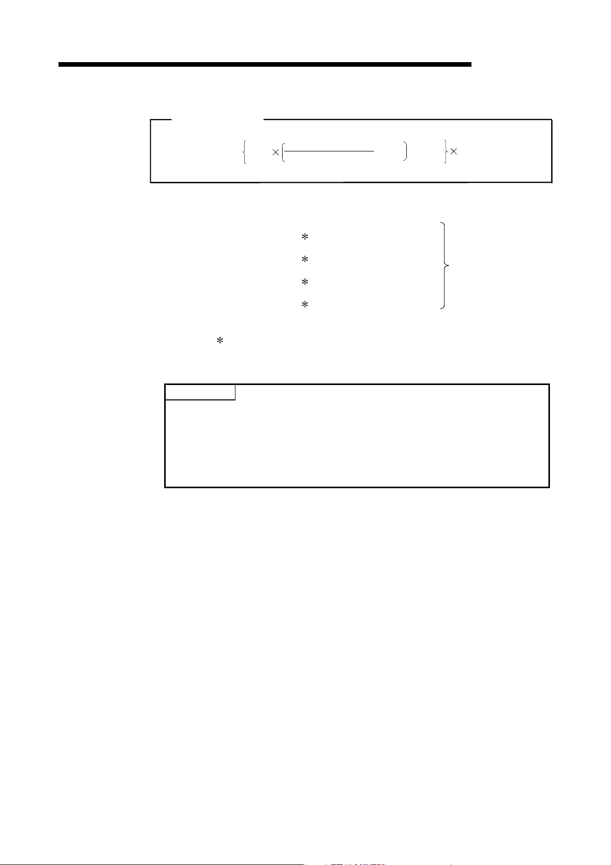
X
Y
3 SPECIFICATIONS
[Link refresh time]
2) Safety CPU
MELSEC-Q
T, R
=
1.85
LB + LX + LY + SB
16
+ LW + 1000
10
-3
[ms]
T : Link refresh time (sending station)
R : Link refresh time (receiving station)
LB : Total points of link relays (LB) refreshed by the
corresponding station
1
LW : Total points of link registers (LW) refreshed by the
corresponding station
: Total points of link inputs (LX) refreshed by the
L
corresponding station
: Total points of link outputs (LY) refreshed by the
L
corresponding station
1
1
1
Refer to Section
3.3.3.
SB : Number of points of the link special relay (SB)
SW : Number of points of the link special register (SW)
1: Total points are the sum of link devices set in refresh parameter
settings and network range settings.
The points assigned for reserved station are not included.
POINT
The values in this section are calculated on the basis that data are received from all
stations during one sequence scan.
When the link scan is long or when the sequence scan is short, data from all
stations may not be received within one sequence scan.
If this occurs, the actual link refresh time is less than the calculated value shown in
this section.
3 - 39 3 - 39
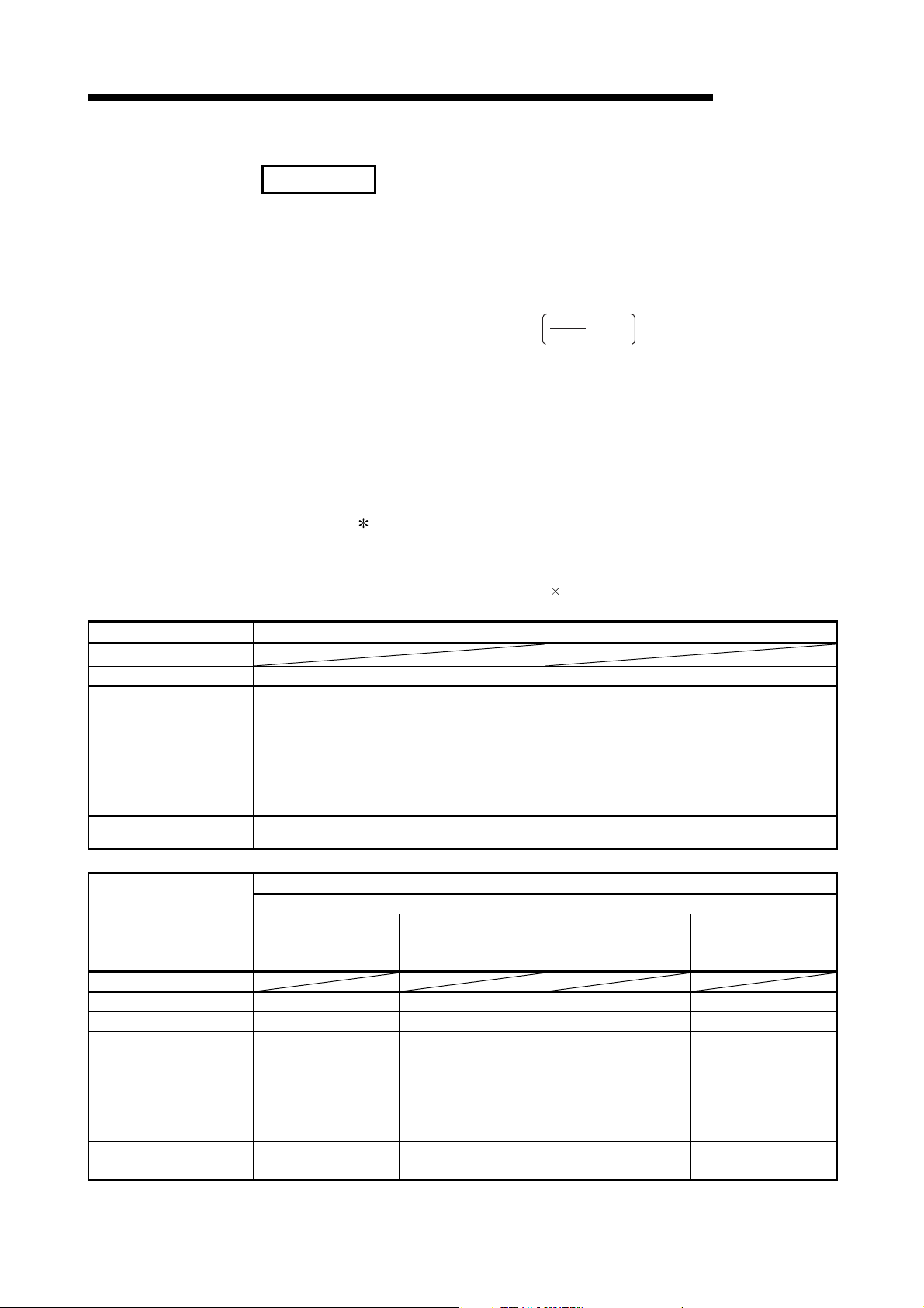
3 SPECIFICATIONS
REMARKS
CPU type
Q00UJ/Q00U/Q01UCPU
Q02UCPU
Q03UD/Q03UDECPU
Q04UDH/Q04UDEH/
Q06UDH/Q06UDEH/
Q10UDH/Q10UDEH/
Q13UDH/Q13UDEH/
Q20UDH/Q20UDEH/
Q26UDH/Q26UDEH/
Q50UDEH/Q100UDEHCPU
Q03UDV/Q04UDV/Q06UDV/
Q13UDV/Q26UDVCPU
CPU type
Q00UJ/Q00U/Q01UCPU
Q02UCPU
Q03UD/Q03UDECPU
Q04UDH/Q04UDEH/
Q06UDH/Q06UDEH/
Q10UDH/Q10UDEH/
Q13UDH/Q13UDEH/
Q20UDH/Q20UDEH/
Q26UDH/Q26UDEH/
Q50UDEH/Q100UDEHCPU
Q03UDV/Q04UDV/Q06UDV/
Q13UDV/Q26UDVCPU
Source (main base) →
Target (main base)
MELSEC-Q
(1) Data link transfer time (for Universal model QCPU)
Universal model QCPUs transfer interlink data in several batches.
The following are the calculation formulas for the data link transfer time.
(a) Data link transfer time taken in one END
→
*1
Source (extension base)
→
Target (extension base)
T
αL = KM4 + (KM5 × n1) ++LWT × KM6 [ms]
LB
16
: Data link transfer time taken in one END
L
n1 : Number of lines where interlink transmission parameters are set
T : Total number of link relay (LB) points set in interlink transmission
LB
parameters
T : Total number of link register (LW) points set in interlink transmission
LW
parameters
KM4, KM5, KM6: Constants
1: The number of words that can be transferred in one END (N) is
restricted as follows:
N = Sequence scan time (under no interlink transmission
parameter setting) (
s) 0.05
KM4(×10
0.76 1.27 1.37 1.79
0.73 1.27 1.37 1.78
0.73 1.25 1.35 1.78
0.73 1.27 1.37 1.78
-3
) KM5(×10-3)
120 11
34 16.3
25 16.3
12 4
Network module mounting position
Source (main base) →
Target (extension base)
KM6(×10
-3
)
Source (extension base)
Target (main base)
3 - 40 3 - 40
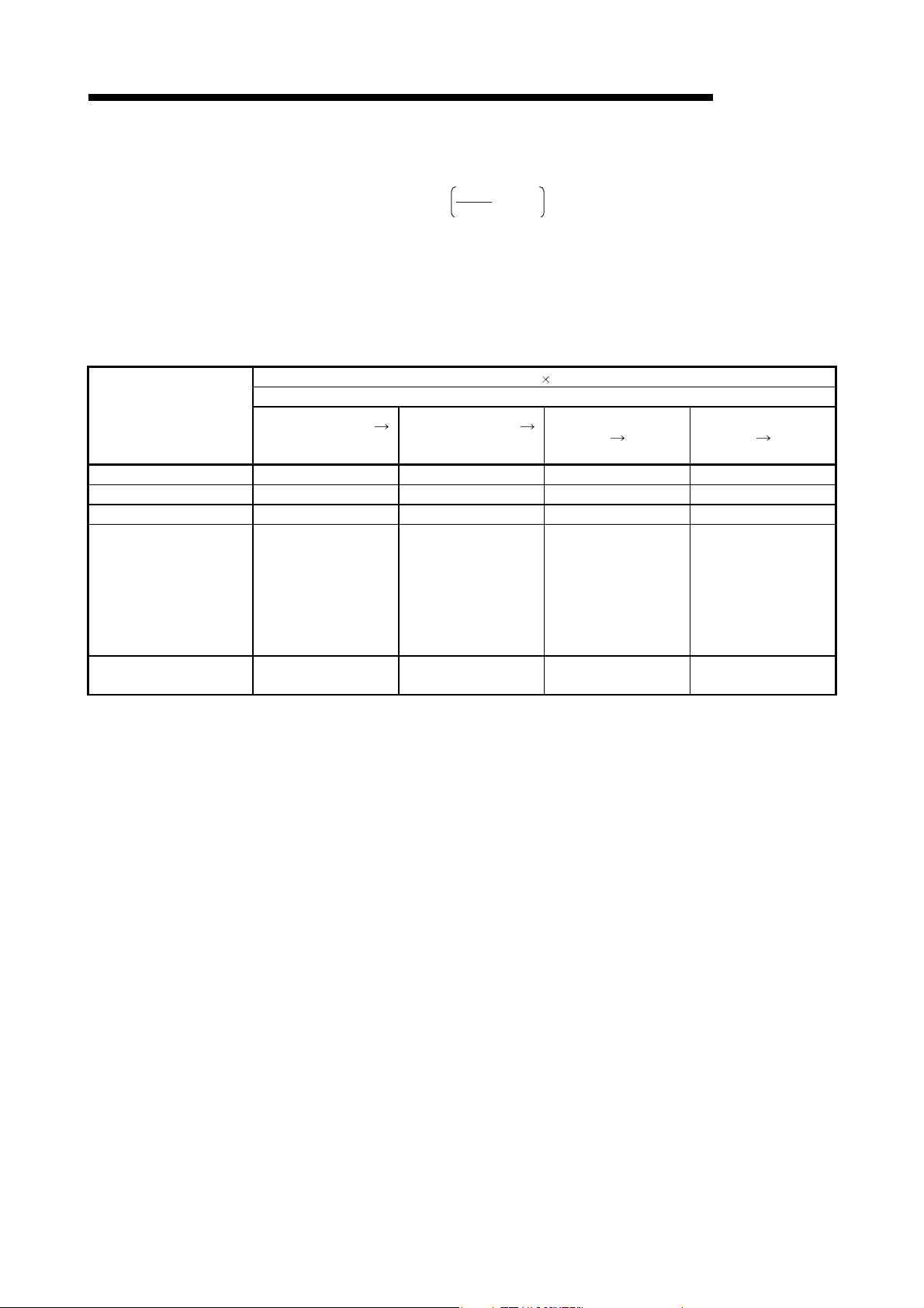
3 SPECIFICATIONS
MELSEC-Q
(b) Data link transfer time required for transferring data of all
CPU type
Q00UJ/Q00U/Q01UCP 25.00 25.20 25.20 25.50
Q02UCPU 25.00 25.20 25.20 25.50
Q03UD/Q03UDECPU 22.10 22.50 22.70 23.00
Q04UDH/Q04UDEH/
Q06UDH/Q06UDEH/
Q10UDH/Q10UDEH/
Q13UDH/Q13UDEH/
Q20UDH/Q20UDEH/
Q26UDH/Q26UDEH/
Q50UDEH/Q100UDEHCPU
Q03UDV/Q04UDV/Q06UDV/
Q13UDV/Q26UDVCPU
Source (main base)
Target (main base)
22.10 22.50 22.70 23.00
22.10 22.50 22.70 23.00
the set points
T
αL1 = KM7× +LWT [ms]
: Data link transfer time taken to transfer all the set points of data
L1
T : Total number of link relay (LB) points set in interlink transmission
LB
parameters
T : Total number of link register (LW) points set in interlink transmission
LW
parameters
KM7: Constants
Source (main base)
Target (extension base)
LB
16
KM7(
Network module mounting position
10-3)
Source (extension base)
Target (main base)
Source (extension base)
Target (extension base)
3 - 41 3 - 41

3 SPECIFICATIONS
[Link scan time]
[Link scan time]
MELSEC-Q
(e) Link scan time in the optical loop system and coaxial bus system
The link scan time in the optical loop system and coaxial bus system is
obtained by the equation below using the following variables:
• Network type
• Number of assignment points of the link device
• Number of connected stations
1) MELSECNET/H mode
a) With a communication speed of 10Mbps
LS = KB + (0.45 total number of stations) +
b) With a communication speed of 25Mbps
LS = KB + (0.40 total number of stations) +
LB + LY + (LW 16)
8
+ (T 0.001) + (F 4) [ms]
LB + LY + (LW 16)
8
0.001
0.0004
+ (T 0.0004) + (F 4) [ms]
LS : Link scan time
Total number of
KB : Constant
stations
KB 4.0 4.5 4.9 5.3 5.7 6.2 6.6 7.0
LB : Total points of link relays (LB) used in all
LW : Total points of link registers (LW) used in all
LX : Total points of link inputs (LX) used in all
LY : Total points of link outputs (LY) used in all
T : Maximum number of bytes sent by the transient transmission in one
F : Number of stations returned to the network (Only if there are faulty
1: Total link device points set up in Network range assignment.
2: The total transfer time when transient transmissions are simultaneously
1 to 8 9 to 16 17 to 24 25 to 32 33 to 40 41 to 48 49 to 56 57 to 64
stations
stations
stations
stations
link scan.
stations. : Maximum number of stations returned to the network in 1
scan (set value))
Note that the points assigned to reserved stations are excluded.
executed from multiple stations.
1
1
1
1
Refer to Section
3.3.3.
2
REMARK
For the link scan time in MELSECNET/10 mode, refer to For QnA/Q4AR
MELSECNET/10 Network System Reference Manual.
3 - 42 3 - 42

3 SPECIFICATIONS
2) MELSECNET/H Extended mode
a) With a communication speed of 10Mbps
[Link scan time]
MELSEC-Q
LS = KB + (0.45 SP) +
LB + LY + (LW 16)
0.001
8
+ (T 0.001) + (F 4) [ms]
b) With a communication speed of 25Mbps
[Link scan time]
LS = KB + (0.40 SP) +
LB + LY + (LW 16)
8
0.0004
+ (T 0.0004) + (F 4) [ms]
LS : Link scan time
Total number of
KB : Constant
stations
KB 4.0 4.5 4.9 5.3 5.7 6.2 6.6 7.0
1 to 8 9 to 16 17 to 24 25 to 32 33 to 40 41 to 48 49 to 56 57 to 64
n
SP=
The calculation example of SP in the setting example is shown in .
Number of bytes sent by station No. (i)
i=1
n=Total number of stations
Number of bytes sent = {(LY + LB) / 8 + (2 x LW)}
1: The number after the decimal point is rounded up. 0 is handled as 1.
a
Setting example
Station No.
Station No. 1
Station No. 2
Station No. 3
Station No. 4
Number of bytes
sent by each
station
2000
8000 bytes
7800 bytes
0 bytes
2000 bytes
b
Calculation example of SP
SP=
1
a
8000
7800
+
2000
200002000
=4 + 4 + 1 + 1
=10
b
++
Number after decimal
point is rounded up.
2000
2000
0 is handled as 1.
LB : Total points of link relays (LB) used in all
stations
2
LW : Total points of link registers (LW) used in all
stations
2
LX : Total points of link inputs (LX) used in all
stations
2
Refer to Section
3.3.3.
LY : Total points of link outputs (LY) used in all
stations
2
T : Maximum number of bytes sent by the transient transmission in one
link scan.
3
F : Number of stations returned to the network (Only if there are faulty
stations. : Maximum number of stations returned to the network in 1
scan (set value))
2: Total link device points set up in the network range parameter
assignment.
Note that the points assigned to reserved stations are excluded.
3: "0" when not used.
3 - 43 3 - 43

3 SPECIFICATIONS
[Link scan time]
LS = KB1+(KB2 total number of stations) + KB3
MELSEC-Q
(f) Link scan time in the twisted bus system
The link scan time in the twisted bus system is obtained by the equation
below using the following variables:
• Network type
• Number of assignment points of the link device
• Constant 1 to 3
1) MELSECNET/H mode
LB+LX+(LW 16)
8
+ (T KB3) + (F 4)
[Link scan time]
LS = KB1+(KB2 SP) + KB3
Total number of stations 1 to 8 9 to 16 17 to 24 25 to 32
KB1 8.0 8.5 8.9 9.3
Communication speed 156kbps 312kbps 625kbps 1.25Mbps 2.5Mbps 5Mbps 10Mbps
KB2 4.6 3.83 3.06 2.55 2.05 1.55 1.05
Communication speed 156kbps 312kbps 625kbps 1.25Mbps 2.5Mbps 5Mbps 10Mbps
KB3 0.064 0.032 0.016 0.008 0.004 0.002 0.001
2) MELSECNET/H Extended mode
LB+LX+(LW 16)
8
LS : Link scan time
KB1 to 3: Constant
LB : Total points of link relays (LB) used in all
stations
LW : Total points of link registers (LW) used in all
stations
LX : Total points of link inputs (LX) used in all
stations
LY : Total points of link outputs (LY) used in all
stations
T : Maximum number of bytes sent by the transient transmission in one
link scan.
F : Number of stations returned to the network (Only if there are faulty
stations. : Maximum number of stations returned to the network in 1
scan (set value))
SP : Refer to Section 3.3.3 (e).
1: Total link device points set up in the network range parameter
assignment.
Note that the points assigned to reserved stations are excluded.
2: "0" when not used.
1
1
1
1
2
+ (T KB3) + (F 4) [ms]
[ms]
Refer to Section
3.3.3.
3 - 44 3 - 44

3 SPECIFICATIONS
(2) Transmission delay time between multiple networks using the inter-
[Inter-link data transfer]
(Transmission delay time)
(Transmission delay time)...For Universal model QCPU
T : Scan time of the sending station (except link refresh time)
S
S
R : Scan time of the receiving station (except link refresh time)
T : Link refresh time of the transmitting station 1
MT : Link refresh time of the relay station and the sending station (for transfer) 1
MR : Link refresh time of the relay station and the receiving station (for transfer) 1
R : Link refresh time of the receiving station 1
LS
T : Link scan time of the sending station
LS
R : Link scan time of the receiving station
K
M : Transmission processing time of the CPU module of the relay station
MELSEC-Q
link data transfer function
The following shows the cyclic transmission delay time for the case where link
device data are transferred to another network with the interlink transfer function.
TD = (ST +
T
= (ST +
D
1: Total for the network modules mounted
) + (LST 1) +
T
) + (LS
T
T
1) +
+ KM +
MR
MR + MT +
+ (LSR 1) + (SR 2) +
MT
(LSR 1) + (S
R
2) +
[ms]
R
[ms]
R
KM = KM6
LB
16
+ LW
1000 + KM7 [ms]
LB : Total of transfer source LB points that are set with interlink transmission
parameters.
LW : Total of transfer source LW points that are set with interlink transmission
parameters.
KM6 : Constant
Transfer source module Transfer target module
Main base unit Main base unit 6.7
Main base unit Extension base unit 10.00
Extension base unit Main base unit 10.00
Extension base unit Extension base unit 12.00
KM7 : 4.5 (Worst value: 60)
Module location
KM6 (
10-3)
POINT
Although KM7 is usually 4.5ms, it can be 60ms if monitoring or a dedicated
instruction is executed from GX Developer or any other station.
Depending on the monitoring timing from GX Developer or another station, the time
may be longer than that.
If the time increase may cause a system problem, use link direct devices in the
sequence program to transfer data.
3 - 45 3 - 45
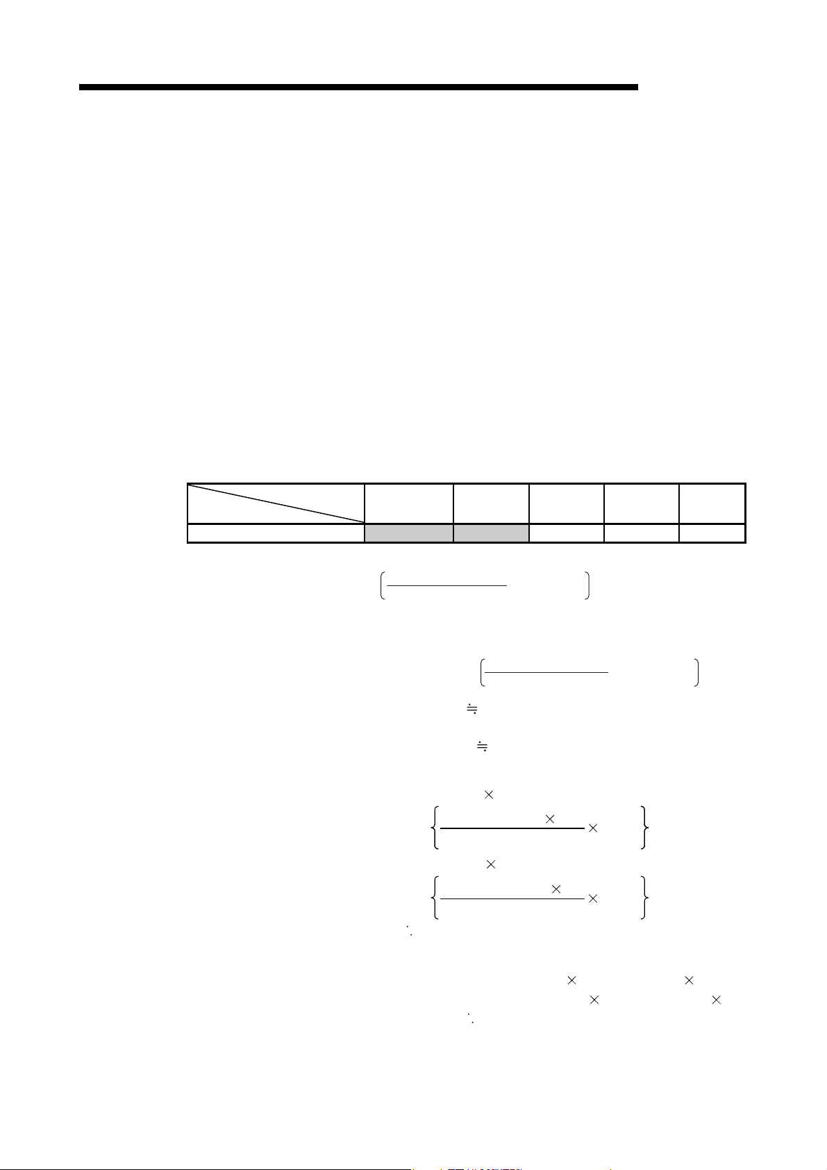
3 SPECIFICATIONS
(3) Example of the transmission delay time calculation
CPU type
Q06HCPU 130 0.41 0.53 250 130
Link refresh time = KM1 + KM2 ×
MELSEC-Q
The following example calculates the transmission delay time with the following
system configuration and under the following conditions:
(System configuration and conditions)
1) CPU module: Q06HCPU
2) Network type: MELSECNET/H mode
3) Communication speed: 10Mbps
4) Total number of stations: 8 stations (1 control station, 7 normal
stations)
5) Number of link device points: LB = 1024 points, LW = 1024 points,
LX = LY = 0 points, SB = SW = 512 points
6) Scan time of the CPU module for all stations: 1 ms
7) The file register is not used.
8) The data inter-link transfer and the transient transmission are not used.
9) The network modules are installed on the basic base unit on all
stations.
<Constants used when network modules are installed on main base unit>
Constant
KM1
(×10
-3
)
KM2
(×10-3)
KM3
(×10-3)
KM4
(×10-3)
KM5
(×10-3)
(a) Link refresh time
LB + LX +LY + SB
16
+ LW + SW
+ α
E
+ α
L
The link refresh time on the sending station α
T
= 130 × 10
1024 + 0 + 0 + 512
×
-3
+ 0.41 × 10
16
-3
+ 1024 + 512 + 0 + 0
0.80 (ms)
The link refresh time on the receiving station α
R
0.80 (ms)
(b) Link scan time
Link scan time LS = KB + (0.45 total number of stations)
(LB + LY + (LW 16)
+
8
0.001
= 4.0 + (0.45 8)
1024 + 0 + (1024 16)
+
9.776 (m s )
=
8
0.001
(c) Cyclic transmission delay
Transmission delay time T
D1 = ST + T + (LS 0.5) + (SR + R) 1.5
= 1 + 0.80 + (9.776
=
9.39 (ms)
0.5) + (1 + 0.80) 15
3 - 46 3 - 46
 Loading...