

Mitsubishi QJ71MT91 User Manual


• SAFETY PRECAUTIONS •
(Always read these instructions before using this equipment.)
Before using this product, please read this manual and the relevant manuals introduced in this manual
carefully and pay full attention to safety to handle the product correctly.
The instructions given in this manual are concerned with this product. For the safety instructions of the
programmable controller system, please read the user's manual of the CPU module to use.
In this manual, the safety instructions are ranked as "DANGER" and "CAUTION".
DANGER
!
CAUTION
!
Note that the !CAUTION level may lead to a serious consequence depending to the circumstances.
Always follow the instructions of both levels because they are important to personal safety.
Please save this manual to make it accessible when required and always forward it to the end user.
Indicates that incorrect handling may cause hazardous conditions,
resulting in death or severe injury.
Indicates that incorrect handling may cause hazardous conditions,
resulting in medium or slight personal injury or physical damage.
[Design Precautions]
!
DANGER
• When controlling a running programmable controller (modifying data) by connecting peripheral
devices to the CPU module or connecting a personal computer to the intelligent function
module, configure an interlocking circuit in a sequence program so that the safety of the overall
system is always maintained. Also, before performing other control operations (program
modifications and operation status modifications (status control)) on the running programmable
controller, be sure to read the manual carefully and thoroughly confirm the safety.
Especially in the above mentioned control operations that are performed from an external device
to a remote programmable controller, any problems on the programmable controller side may
not be dealt with promptly due to a data communication error. In addition to configuring an
interlocking circuit in a sequence program, determine how the system handles data
communication errors, etc. between the devices and the programmable controller CPU.
• Do not write any data in the "system area (Use prohibited)" of the buffer memory of the
intelligent function module. Also, do not output (turn on) the "use prohibited" signal, which is one
of the output signals from the programmable controller CPU to the intelligent function module. If
data is written to the "system area (Use prohibited)" or the "use prohibited" signal is output, there
is a risk that the programmable controller system may malfunction.
A - 1 A - 1
!
CAUTION
• Do not bundle the control wires and the communication cables with the main circuit and the
power wires, and do not install them close to each other. They should be installed at least 100
mm (3.94 in.) away from each other. Failure to do so may generate noise that may cause
malfunctions.
[Installation Precautions]
!
DANGER
• Use the programmable controller in the operating environment that meets the general
specifications described in the user's manual of the CPU Module to use. Using the
programmable controller in any other operating environments may cause electric shocks, fires
or malfunctions, or may damage or degrade the module.
• While pressing the installation lever located at the bottom of the module, insert the module fixing
projection into the fixing hole in the base unit to mount the module.
Incorrect module mounting may cause a malfunction, failure, or drop of the module.
In an environment of frequent vibrations, secure the module with the screw.
• Be sure to tighten the screws using the specified torque. If the screws are loose, it may cause
the module to short-circuit, malfunction or fall off. If the screws are tightened excessively, it may
damage the screws and cause the module to short-circuit, malfunction or fall off.
• Do not directly touch any conductive part or electronic component of the module.
Doing so may cause a malfunction or failure of the module.
!
CAUTION
• Be sure to shut off all phases of the external power supply used by the system before mounting
or removing the module.
Failure to do so may damage the module.
[Wiring Precautions]
!
CAUTION
• Be sure to shut off all phases of the external power supply before installation or wiring.
Failure to do so may result in an electric shock or damage to the product.
• Use crimp-contact, pressure-displacement or soldering to wire the connectors for external
connections properly using the manufacturer-specified tools.
If the connection is incomplete, it may cause the module to short circuit, catch fire, or
malfunction.
A - 2 A - 2

!
CAUTION
• Securely connect the connector to the module.
• Make sure to place the communication and power cables to be connected to the module in a
duct or fasten them using a clamp. If the cables are not placed in a duct or fastened with a
clamp, their positions may be unstable or moved, and they may be pulled inadvertently.
This may damage the module and the cables or cause the module to malfunction because of
faulty cable connections.
• Wire the module correctly after confirming the type of the connected interface. If the cable is
connected to a different interface or wired incorrectly, it may cause a fire or breakdown.
• When disconnecting the communication and power cables from the module, do not pull the
cables by hand. When disconnecting a cable with a connector, hold the connector to the module
by hand and pull it out to remove the cable. If the cable is pulled while being connected to the
module, it may damage the module and/or cable or make cable contact improper, causing a
malfunction.
• Be careful not to let any foreign matter such as wire chips get inside the module.
They may cause fire, as well as breakdowns and malfunctions of the module.
• A protective sheet is pasted on the upper part of the module in order to prevent foreign matter
such as wire chips to get inside the module while wiring.
Do not remove this protective sheet during wiring work. However, be sure to remove the
protective sheet before operating the module to allow heat radiation during operation.
[Setup and Maintenance Precautions]
!
DANGER
• Do not touch the terminals while the power is on. Doing so may cause electric shocks or
malfunctions.
• Before cleaning the module or retightening the module mounting screws, make sure to shut off
all phases of the external power supply used by the system. Failure to do so may cause the
module to electric shocks, breakdown or malfunction. If the screws are loose, it may cause the
module to short-circuit, malfunction or fall off. If the screws are tightened excessively, it may
damage the screws and cause the module to short circuit, malfunction or fall off.
A - 3 A - 3
!
CAUTION
• Before performing online operations (especially, program modification, forced output or
operating status change) by connecting a peripheral device to a running CPU, read the manual
carefully and ensure the safety. Incorrect operation will cause mechanical damage or accidents.
• Never disassemble or modify the module. This may cause breakdowns, malfunctions, injuries or
fire.
• When using a wireless communication device such as a cellular phone, keep a distance of 25cm
(9.85 inch) or more from the programmable controller in all directions. Failure to do so can
cause a malfunction.
• Before mounting/dismounting the module, be sure to shut off all phases of the external power
supply used by the system. Failure to do so may cause module failure or malfunctions.
• Do not install/remove the module to/from the base unit more than 50 times after the first use of
the product. (IEC 61131-2 compliant)
Failure to do so may cause malfunction.
• Always make sure to touch the grounded metal to discharge the electricity charged in the body,
etc., before touching the module.
Failure to do so may cause a failure or malfunctions of the module.
[Operating Precautions]
!
CAUTION
• Please read the manual carefully and confirm the safety thoroughly before performing control
operations (especially, modifications of data, programs and operation status (status control)) of
the programmable controller that is running.
Incorrect modifications of data, programs and operating status may cause system malfunctions,
damages to the machines, or accidents.
[Disposal Precautions]
!
CAUTION
• Dispose of this product as an industrial waste.
A - 4 A - 4
REVISIONS
The manual number is given on the bottom left of the back cover.
Print Date Manual Number Revision
Jan., 2004 SH (NA) -080446ENG-A First Edition
Mar., 2004 SH (NA) -080446ENG-B
Modifications
Section 7.2.2, 8.3.2, 8.4, 8.6, 8.7, 9.2.2, 11.1, 11.4, 11.5
Nov., 2005 SH (NA) -080446ENG-C
Modifications
Section 4.3.10, 5.2.1, 6.1, 6.2, 6.6, 7.1, 7.3.1, 7.4.1 to 7.4.5, 8.2.2,
8.3.1, 8.3.3, 8.7.2, 9.1, 10.2, 10.3, 11.1, 11.2, 11.3.2, 11.3.3, 11.4
Feb., 2006 SH (NA) -080446ENG-D
Modifications
Section 2.1, 2.4, 10.1
Jan., 2008 SH (NA) -080446ENG-E
Modifications
SAFETY PRECAUTIONS, Conformation to the EMC Directive and
Low Voltage Instruction, About the Generic Terms and
Abbreviations, Section 2.1, 2.5, 3.1, 3.2.1, 5.1, 5.2.1, 5.5, 6.1, 6.4,
6.6, 7.2.2, 7.4.1, 7.4.2, 7.4.4, Chapter 8, Section 9.1.3, 9.3.1, 9.3.2,
9.3.3, 10.2, 10.3, 11.1, 11.2, 11.3.1, 11.3.3, 11.4.1, 11.4.2, 11.5.1
Addition
Section 2.4
May, 2008 SH (NA) -080446ENG-F
Change of a term
"PLC" was changed to "programmable controller".
Modifications
SAFETY PRECAUTIONS, Compliance with the EMC and Low
Voltage Directives, About the Generic Terms and Abbreviations,
Section 2.1, 3.1, 6.1, 6.6, 7.4.2, 8.2.1, 8.3.1, 8.3.3, 8.6, 10.2, 10.3,
11.2, 11.3.3, Appendix 3
Japanese Manual Version SH(NA)-080445-G
This manual confers no industrial property rights or any rights of any other kind, nor does it confer any patent
licenses. Mitsubishi Electric Corporation cannot be held responsible for any problems involving industrial property
rights which may occur as a result of using the contents noted in this manual.
© 2004 MITSUBISHI ELECTRIC CORPORATION
A - 5 A - 5

INTRODUCTION
Thank you for purchasing the MELSEC-Q series programmable controller.
Before using the equipment, please read this manual carefully to develop full familiarity with the functions
and performance of the Q series programmable controller you have purchased, so as to ensure correct use.
CONTENTS
SAFETY PRECAUTIONS..............................................................................................................................A- 1
REVISIONS ....................................................................................................................................................A- 5
INTRODUCTION............................................................................................................................................A- 6
CONTENTS....................................................................................................................................................A- 6
Compliance with the EMC and Low Voltage Directives................................................................................A-10
The Manual's Usage and Structure ...............................................................................................................A-11
About the Generic Terms and Abbreviations ................................................................................................A-13
Meanings and Definitions of Terms ..............................................................................................................A-14
Product Configuration ....................................................................................................................................A-14
1 OVERVIEW 1- 1 to 1- 5
1.1 Features ................................................................................................................................................... 1- 1
2 SYSTEM CONFIGURATION 2- 1 to 2- 9
2.1 Applicable Systems.................................................................................................................................. 2- 1
2.2 Devices Necessary for Network Configuration .......................................................................................2- 4
2.3 System Configuration and Access Range .............................................................................................. 2- 5
2.4 Precautions for System Configuration..................................................................................................... 2- 7
2.5 How to Check the Function Version and Software Version ................................................................... 2- 8
3 SPECIFICATIONS 3- 1 to 3- 9
3.1 Performance Specifications ..................................................................................................................... 3- 1
3.2 I/O Signals for Programmable Controller CPU ....................................................................................... 3- 2
3.2.1 I/O signal list ...................................................................................................................................... 3- 2
3.3 Applications and Assignment of Buffer Memory ..................................................................................... 3- 4
3.3.1 Buffer memory list ............................................................................................................................. 3- 4
4 MODBUS
R
STANDARD FUNCTIONS 4- 1 to 4-20
4.1 MODBUSR Standard Function Support List........................................................................................... 4- 1
4.2 Frame Specifications ............................................................................................................................... 4- 3
4.3 PDU Formats by Functions...................................................................................................................... 4- 4
4.3.1 Read coils (FC: 01) ........................................................................................................................... 4- 6
4.3.2 Read discrete inputs (FC: 02)........................................................................................................... 4- 7
4.3.3 Read holding registers (FC: 03)........................................................................................................ 4- 8
4.3.4 Read input registers (FC: 04) ........................................................................................................... 4- 9
4.3.5 Write single coil (FC: 05)................................................................................................................... 4-10
4.3.6 Write single register (FC: 06) ............................................................................................................ 4-11
4.3.7 Write multiple coils (FC: 15).............................................................................................................. 4-12
4.3.8 Write multiple registers (FC: 16) ....................................................................................................... 4-14
A - 6 A - 6

4.3.9 Read file record (FC: 20) (SC: 06).................................................................................................... 4-15
4.3.10 Write file record (FC: 21) (SC: 06) .................................................................................................. 4-17
4.3.11 Mask write register (FC: 22) ........................................................................................................... 4-19
4.3.12 Read/Write multiple registers (FC: 23) ........................................................................................... 4-20
5 FUNCTIONS 5- 1 to 5-15
5.1 Function List .............................................................................................................................................5- 1
5.2 Master Function ....................................................................................................................................... 5- 3
5.2.1 Automatic communication function................................................................................................... 5- 3
5.2.2 Dedicated instructions ....................................................................................................................... 5- 9
5.3 Slave Function.......................................................................................................................................... 5-10
5.3.1 Automatic response function ............................................................................................................ 5-10
5.3.2 MODBUS
®
device assignment function ........................................................................................... 5-11
5.4 KeepAlive Function .................................................................................................................................. 5-12
5.5 Router Relay Function ............................................................................................................................. 5-14
5.6 GX Developer Connection Function........................................................................................................ 5-15
6 PRE-OPERATIONAL PROCEDURES AND SETTING 6- 1 to 6-19
6.1 Handling Precautions ............................................................................................................................... 6- 1
6.2 Pre-Operational Procedures and Setting ................................................................................................ 6- 2
6.3 Part Names .............................................................................................................................................. 6- 4
6.4 Connection to Ethernet ............................................................................................................................ 6- 6
6.5 Unit Tests ................................................................................................................................................. 6- 8
6.5.1 Hardware test .................................................................................................................................... 6- 8
6.5.2 Self-loopback test .............................................................................................................................. 6- 9
6.6 Intelligent Function Module Switch Setting ............................................................................................. 6-10
6.6.1 Communication starting conditions depending on basic parameter/MODBUS
R
device assignment
parameter starting method setting .................................................................................................... 6-15
7 PARAMETER SETTING 7- 1 to 7-33
7.1 Parameter Settings and Setting Procedure ............................................................................................ 7- 1
7.2 Basic Parameters..................................................................................................................................... 7- 6
7.2.1 Basic parameters details ................................................................................................................... 7- 6
7.2.2 TCP/UDP/IP setting .......................................................................................................................... 7- 8
7.2.3 GX Developer connection information setting.................................................................................. 7-16
7.2.4 MODBUS
®
/TCP setting..................................................................................................................... 7-17
7.3 Automatic Communication Parameters................................................................................................... 7-19
7.3.1 Automatic communication parameters details .................................................................................7-19
7.4 MODBUS
7.4.1 MODBUS
7.4.2 MODBUS
®
Device Assignment Parameters ........................................................................................... 7-23
®
device sizes .................................................................................................................... 7-25
®
device assignment parameters details .......................................................................... 7-26
7.4.3 Default assignment parameters........................................................................................................ 7-29
7.4.4 MODBUS
®
extended file register assignment.................................................................................. 7-31
7.4.5 QJ71MT91 buffer memory assignment ............................................................................................ 7-32
8 UTILITY PACKAGE (GX Configurator-MB) 8- 1 to 8-36
8.1 Functions of the Utility Package .............................................................................................................. 8- 1
A - 7 A - 7

8.2 Installing and Uninstalling the Utility Package ........................................................................................ 8- 2
8.2.1 Handling precautions ........................................................................................................................ 8- 2
8.2.2 Operating environment...................................................................................................................... 8- 4
8.3 Utility Package Operation ........................................................................................................................ 8- 6
8.3.1 Common utility package operations ................................................................................................. 8- 6
8.3.2 Operation overview ........................................................................................................................... 8- 9
8.3.3 Starting the Intelligent function module utility ................................................................................... 8-11
8.4 Initial Setting ............................................................................................................................................. 8-13
8.5 Auto Refresh Setting ................................................................................................................................ 8-15
8.6 Monitor/Test ............................................................................................................................................. 8-17
8.6.1 X/Y Monitor/test ................................................................................................................................. 8-21
8.6.2 Basic/MODBUS
®
device assignment parameter status .................................................................. 8-23
8.6.3 Automatic communication status ...................................................................................................... 8-24
8.6.4 Error log ............................................................................................................................................. 8-26
8.6.5 Communication status....................................................................................................................... 8-27
8.6.6 PING test ...........................................................................................................................................8-29
8.7 Parameter Setting Using GX Configurator-MB ....................................................................................... 8-30
8.7.1 Basic parameters .............................................................................................................................. 8-30
8.7.2 Automatic communication parameters ............................................................................................. 8-33
8.7.3 MODBUS
®
device assignment parameters...................................................................................... 8-35
9 PROGRAMMING 9- 1 to 9-49
9.1 Parameter Setting .................................................................................................................................... 9- 1
9.1.1 Basic parameter setting ....................................................................................................................9- 1
9.1.2 Automatic communication parameter setting ................................................................................... 9- 4
9.1.3 MODBUS
®
device assignment parameter setting ........................................................................... 9- 7
9.2 Program Example for Normal System Configuration.............................................................................. 9-11
9.2.1 System configuration and program conditions ................................................................................. 9-11
9.2.2 Program using utility package........................................................................................................... 9-18
9.2.3 Program without using utility package.............................................................................................. 9-22
9.3 Program Example for Use in MELSECNET/H Remote I/O Network ..................................................... 9-29
9.3.1 System configuration and program conditions ................................................................................. 9-29
9.3.2 Program using utility package........................................................................................................... 9-35
9.3.3 Program without using utility package.............................................................................................. 9-39
10 DEDICATED INSTRUCTIONS 10- 1 to 10-18
10.1 Dedicated Instruction List and Available Devices ............................................................................... 10- 1
10.2 Z(P).MBRW .......................................................................................................................................... 10- 2
10.3 Z(P).MBREQ ........................................................................................................................................10-11
11 TROUBLESHOOTING 11- 1 to 11-48
11.1 Troubleshooting ................................................................................................................................... 11- 1
11.2 Confirming QJ71MT91 Status .............................................................................................................11-10
11.3 Error Codes .......................................................................................................................................... 11-13
11.3.1 Error code storage areas .............................................................................................................. 11-13
11.3.2 Exception code list ........................................................................................................................11-19
11.3.3 Error code list ................................................................................................................................11-21
A - 8 A - 8

11.4 Turning Off the COM.ERR. LED .........................................................................................................11-37
11.4.1 From GX Configurator-MB............................................................................................................ 11-37
11.4.2 Program example for use of sequence program ......................................................................... 11-40
11.5 Conducting PING Test to Check QJ71MT91 Connection .................................................................. 11-41
11.5.1 From GX Configurator-MB............................................................................................................ 11-42
11.5.2 Program example for use of sequence program ......................................................................... 11-46
APPENDICES App- 1 to App- 7
Appendix 1 External Dimensions................................................................................................................App- 1
Appendix 2 Processing Time ......................................................................................................................App- 2
Appendix 3 GX Developer Connection Setup Example ............................................................................App- 5
INDEX Index- 1 to Index- 4
A - 9 A - 9
Compliance with the EMC and Low Voltage Directives
(1) For programmable controller system
To configure a system meeting the requirements of the EMC and Low Voltage
Directives when incorporating the Mitsubishi programmable controller (EMC and
Low Voltage Directives compliant) into other machinery or equipment, refer to
Chapter 9 "EMC AND LOW VOLTAGE DIRECTIVES" of the QCPU User's
Manual (Hardware Design, Maintenance and Inspection).
The CE mark, indicating compliance with the EMC and Low Voltage Directives, is
printed on the rating plate of the programmable controller.
(2) For the product
Note the following when making this product to conform to the EMC and Low
Voltage directives.
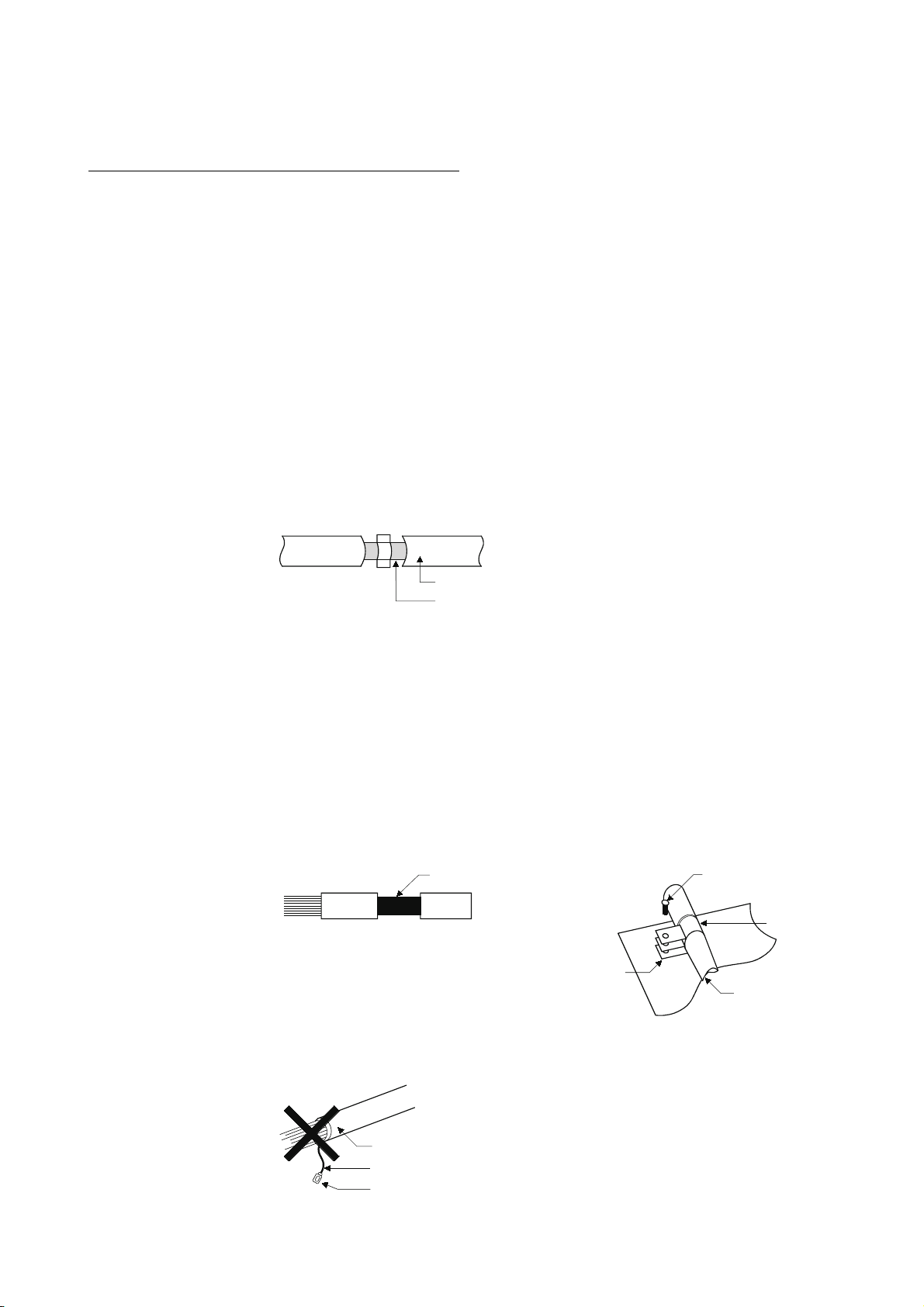
(a) Twisted pair cable
Use shielded twisted pair cables for connecting to the 10BASET/100BASE-TX connectors. For the shielded twisted pair cables, strip a
part of the outer cover and ground the exposed shield section on the widest
contact surface as shown below.
Shielded twisted pair cables
Shield
Refer to (b) for grounding of the shield.
(b) Grounding of shield of shielded cable
1) Ground the shield of the shielded cable as close to the
module as possible to avoid the electromagnetic induction
from ungrounded cables.
2) Take an appropriate measure so that the stripped shield
section can be grounded to the control panel in the largest
area as possible. A clamp may be used as shown below.
In this case, however, mask the contact part when painting
the inner surface of the control panel to allow it to contact
Note) Grounding by soldering a wire onto the shield section of the shielded cable as
shown below is not recommended. The high frequency impedance will increase
and the shield will be ineffective.
with the clamp.
Shield section
Screw
Clamp
Paint mask
Shielded cable
Shielded cable
Wire
Crimp terminal
A - 10 A - 10

The Manual's Usage and Structure
How to use this manual
This manual describes the pre-operation procedure, functions, etc. by use of the
MODBUS
Refer to the corresponding section when you need to know the following:
(1) Features (Chapter 1)
Chapter 1 describes the features of the QJ71MT91.
(2) System configuration (Chapter 2)
(a) Section 2.1 describes the applicable programmable controller CPUs and
compatible software packages.
(b) Section 2.2 describes the devices necessary to configure a network.
(c) Section 2.3 describes the system configurations that use the QJ71MT91 and
the accessible range.
(3) Performance and specifications (Chapter 3)
(a) Section 3.1 provides the performance specifications of the QJ71MT91.
(b) Section 3.2 and 3.3 give the I/O signal and buffer memory lists of the
QJ71MT91.
(4) MODBUSR standard functions supported by the QJ71MT91
(Chapter 4)
(a) Section 4.1 gives a list of MODBUSR standard functions supported by the
QJ71MT91.
(b) Section 4.2 and 4.3 provide the frame specifications of the MODBUS
standard functions supported by the QJ71MT91.
(5) Usable functions (Chapter 5)
Chapter 5 describes the functions of the QJ71MT91.
R
/TCP interface module (QJ71MT91) on a purpose-by-purpose basis.
R
A - 11 A - 11

(6) Settings and procedures necessary to operate the system (Chapter
6)
Chapter 6 describes the pre-operation settings and procedures.
(7) Parameter setting of the QJ71MT91 (Chapter 7)
Chapter 7 describes the parameter setting procedures and parameter details.
(8) Parameter setting from the utility package (Chapter 8)
Chapter 8 describes the utility package operation method.
(9) Parameter setting from sequence programs (Chapter 9)
Chapter 9 describes the I/O signals used for parameter setting, the I/O signal
timing charts, and program examples.
(10) Reading/Writing, etc. of MODBUSR device data with sequence
programs (Chapter 10)
Chapter 10 describes the dedicated instructions designed to perform read/write,
etc. of MODBUS
R
device data with sequence programs.
(11) Error codes and corresponding corrective actions (Chapter 11)
(a) Section 11.1 describes the troubleshooting.
(b) Section 11.2 describes how to check the module condition.
(c) Section 11.3 describes the error code storage location and details.
(d) Section 11.4 describes how to turn OFF the COM.ERR. LED.
(e) Section 11.5 describes the PING test.
About the notation of the numerical values used in this manual
Among the numerical values used in this manual, "H" is placed to the right of the
units place for hexadecimal notation.
(Example) 10 ..... Decimal
10
H ... Hexadecimal
A - 12 A - 12
About the Generic Terms and Abbreviations
Unless otherwise specified, this manual uses the following generic terms and
abbreviations to explain the QJ71MT91 MODBUS
R
/TCP interface module.
Generic Term/Abbreviation
QJ71MT91 Abbreviation for the QJ71MT91 MODBUSR/TCP interface module.
MODBUSR/TCP
MODBUSRserial protocol
Generic term for the protocol designed to use MODBUS
TCP/IP network.
Generic term for the protocol designed to use MODBUS
serial interface.
FC Abbreviation for the function code.
SC Abbreviation for the sub code.
Generic term for the Q00JCPU, Q00CPU, Q01CPU, Q02CPU, Q02HCPU,
Q06HCPU, Q12HCPU, Q25HCPU, Q02PHCPU, Q06PHCPU, Q02PHCPU,
Programmable controller CPU
Q25PHCPU, Q12PRHCPU, Q25PRHCPU, Q02UCPU, Q03UDCPU, Q04UDHCPU
Q06UDHCPU, Q13UDHCPU, Q26UDHCPU, Q03UDECPU, Q04UDEHCPU,
Q06UDEHCPU, Q13UDEHCPU and Q26UDEHCPU.
Generic product name for SWnD5C-GPPW-E, SWnD5C-GPPW-EA, SWnD5C-
GX Developer
GPPW-EV, and SWnD5C-GPPW-EVA. ("n" means version 4 or later.)
"-A" and "-V" mean "volume license product" and "version-upgrade product"
respectively.
Ethernet module The QJ71E71-100 Ethernet interface module.
A machine-specific address that is also referred to as the MAC (Media Access Control)
Ethernet Address
address. This is used to identify the addresses of external devices over a network.
The Ethernet address of the QJ71MT91 can be verified on the MAC ADD column of
the rating plate.
MELSECNET/H The MELSECNET/H network system.
Master The side from which a request is sent to execute a function.
Slave
Master function
Slave function
Request message
The side where the execution request from the master is processed and its execution
result is sent.
The function that allows communication with the MODBUS
device as the master of MODBUS
The function that allows communication with the MODBUS
device as the slave of MODBUS
The message used to give a function execution request to the slave
In the MODBUS
R
protocol, a function execution request is given from the master to
the slave.
A function execution request cannot be given from the slave to the master.
Response message The message with which the slave returns a function execution result to the master.
Generic term for the communication targets connected for data communication.
Target device
(personal computer, other QJ71MT91 MODBUSR/TCP interface module, MODBUSR
protocol compatible device, etc.)
Personal computer The IBM PC/AT or compatible DOS/V-based personal computer.
MBRW Abbreviation for Z.MBRW or ZP.MBRW.
MBREQ Abbreviation for Z.MBREQ or ZP.MBREQ.
Description
R
/TCP.
R
/TCP.
R
protocol messages on a
R
protocol messages on a
R
/TCP compatible slave
R
/TCP compatible master
A - 13 A - 13
Generic Term/Abbreviation
Windows VistaR
WindowsRXP
Generic term for the following:
Microsoft
R
Windows VistaRHome Basic Operating System,
MicrosoftRWindows VistaRHome Premium Operating System,
MicrosoftRWindows VistaRBusiness Operating System,
MicrosoftRWindows VistaRUltimate Operating System,
Microsoft
R
Windows VistaREnterprise Operating System
Generic term for the following:
MicrosoftRWindowsRXP Professional Operating System,
Microsoft
R
WindowsRXP Home Edition Operating System
Description
Meanings and Definitions of Terms
The following explains the meanings and definitions of the terms used in this manual.
Term
MODBUSRprotocol Communication protocol developed for programmable controller by Schneider Electric SA.
MODBUSRdevice Device used for communication using the MODBUSRprotocol.
Programming system devised to make a contact type sequence compatible with the
Sequence program
programmable controller language as-is. Draw two vertical control buses and describe
contacts, etc. between the buses to perform programming.
Device memory
Memory provided for the programmable controller CPU to record the data handled in
sequence program operation.
Meaning/Definition
Product Configuration
The following indicates the product configuration of the QJ71MT91 MODBUS
Model
QJ71MT91 QJ71MT91 MODBUSR/TCP interface module 1
SW1D5C-QMBU-E GX Configurator-MB Version 1 (1-license product) (CD-ROM) 1
SW1D5C-QMBU-EA GX Configurator-MB Version 1 (Multiple-license product) (CD-ROM) 1
interface module.
Item name
R
/TCP
Quantity
A - 14 A - 14
1 OVERVIEW
MELSEC-Q
1 OVERVIEW
1.1 Features
This manual explains the specifications, functions, programming, troubleshooting, etc.
of the MELSEC-Q series QJ71MT91 MODBUS
R
/TCP interface module (hereafter
abbreviated to the QJ71MT91).
The QJ71MT91 is used to connect the MELSEC-Q series programmable controller to
a MODBUS
R
/TCP network.
MODBUS is a registered trademark of Schneider Electric SA.
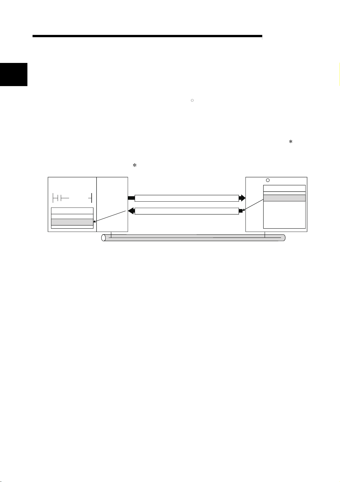
(1) Supporting master function of MODBUSR/TCP communication
The QJ71MT91 supports the master function of MODBUSR/TCP
communication, which is an open network system for factory automation, and it is
compatible with various MODBUS
R
/TCP slave devices (hereafter abbreviated to
the slaves) of other manufactures.
The master function supports the following two functions.
(a) Automatic communication function
By setting the automatic communication parameters, MODBUSR device
data can be automatically read from or written to the slaves at the specified
intervals using the QJ71MT91 buffer memory. (
Data can be transferred between the QJ71MT91 buffer memory and
programmable controller CPU device memory by making the auto refresh
setting with the utility package (GX Configurator-MB) or accessing a
intelligent function module device with a sequence program.
Ethernet
Holding register
1)
MODBUS /TCP slave device
(Third party remote I/O, etc.)
R
1
Programmable
controller CPU
Device memory
Auto refresh
QJ71MT91
MODBUS device read/write request
messages are issued to the slave
repeatedly at specified intervals.
(Master function
Buffer memory
100ms read
250ms read
1000ms read
100ms write
R
)
MODBUS /TCP slave device
(Third party sensor, etc.)
Holding register
MODBUS /TCP slave device
(Third party programmable
controller)
Holding register
R
R
1: The MODBUSR device indicates the device area of the slave where data can be read/written in
response to a request from the master.
1 - 1 1 - 1
1 OVERVIEW
1
Programmable
controller CPU
Command
[Z.MBRW ]
(b) Communication using dedicated instruction
Dedicated instructions can be used to make communication from a
sequence program at any timing.
The QJ71MT91 supports the following two dedicated instructions.
1) MBRW instruction
Reads/writes MODBUSR device data from/to a slave.
This enables slave data to be read out to the programmable controller
CPU device memory or programmable controller CPU data to be
written to the slave.
2) MBREQ instruction
Can issue user-desired request message format (function code 1 +
data unit) to a slave.
1: Refer to Chapter 4 for the function code.
QJ71MT91
(Master function)
Request message (holding register 400500 read request)
MELSEC-Q
MODBUS /TCP slave device
400500
R
Holding register
H
1234
Device memory
H
1234
Response message (holding register 400500 = 1234H)
Ethernet
1 - 2 1 - 2
1 OVERVIEW
Programmable
controller CPU
Sequence program
not needed
Device memory
MELSEC-Q
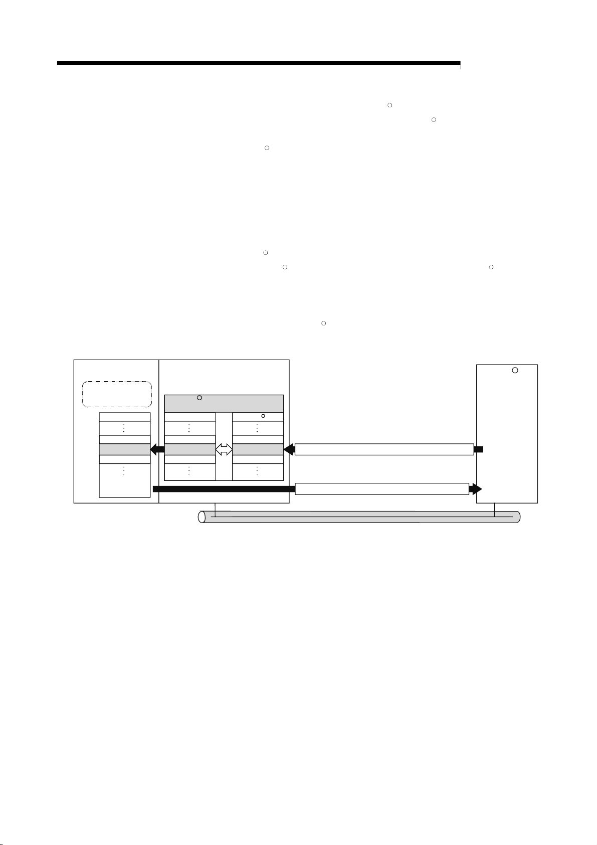
(2) Supporting slave function of MODBUSR/TCP communication
The QJ71MT91 supports the slave function of MODBUSR/TCP communication,
which is an open network system for factory automation, and it is compatible with
various MODBUS
R
/TCP master devices (hereafter abbreviated to the masters)
of other manufacturers.
The slave function supports the following two functions.
(a) Automatic response function
The QJ71MT91 can automatically respond to a request message received
from the master.
A sequence program for the slave function is not needed.
(b) MODBUSR device assignment function
Using MODBUSRdevice assignment parameters, the MODBUSRdevices
are correlated with the programmable controller CPU device memory.
This enables direct access from the master to the programmable controller
CPU device memory.
Supporting the MODBUS
all device memories of the programmable controller CPU to be assigned.
QJ71MT91(Slave function)
MODBUS
device assignment parameters
R
Device memory
MODBUS device
R
R
devices of large capacity, the QJ71MT91 allows
MODBUS /TCP
master device
R
D300
1234
D299
H
D300 400500
D301 400501
400499
Request message (holding register 400500 read request)
Response message (holding register 400500 = 1234H)
Ethernet
1 - 3 1 - 3
1 OVERVIEW
MELSEC-Q
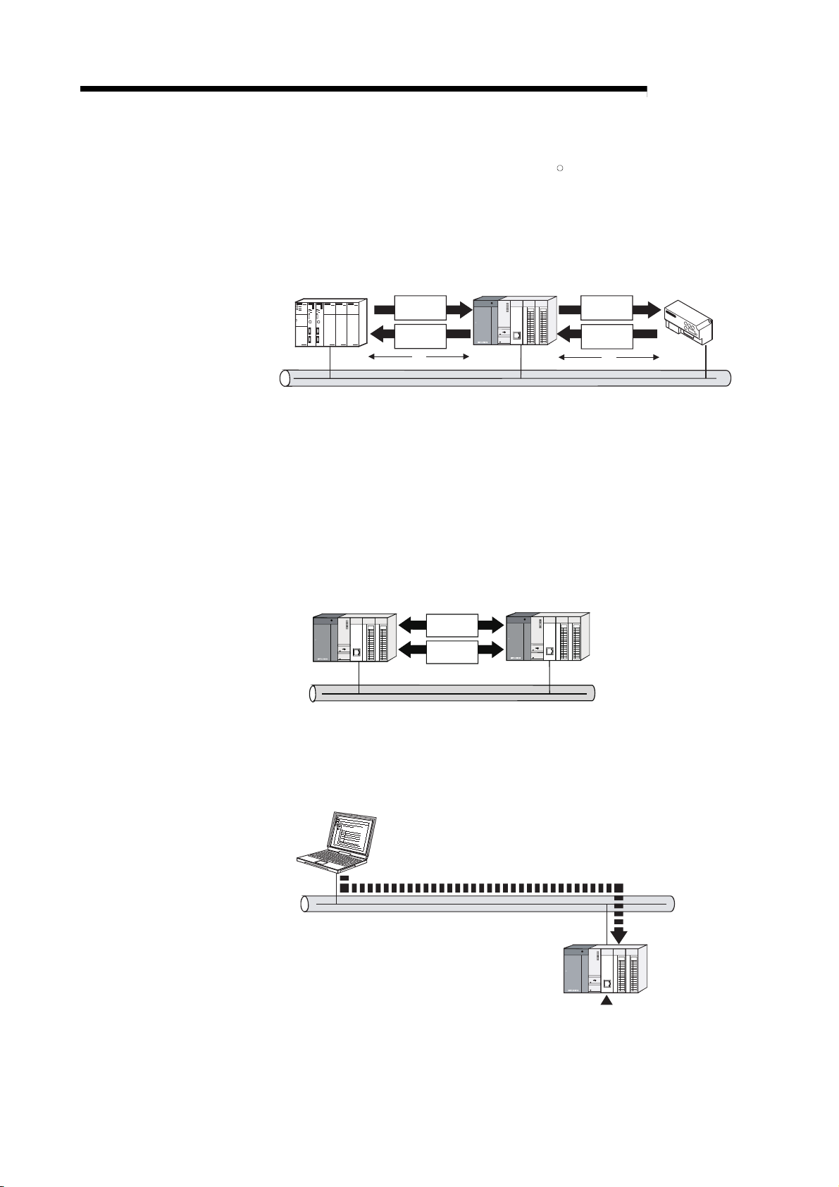
(3) Concurrent operation of master and slave functions
The master and slave functions can be operated concurrently.
This enables flexible construction of a MODBUS
system.
R
/TCP communication-based
(a) Example of communication between QJ71MT91 and third
party devices
Third party
programmable controller
(Master)
Ethernet
Master Slave
Request
message
Response
message
1)
QJ71MT91
(Master/slave function)
Master
Request
message
Response
message
2)
1) In response to a request message from the master, the QJ71MT91
operates as a slave and returns a response message.
2) The QJ71MT91 operates as a master, and issues a request message
to the slave.
Third party remote I/O
(Slave)
Slave
(b) Example of communication between QJ71MT91 and
QJ71MT91
The both functions can be operated bi-directionally between QJ71MT91
and QJ71MT91.
QJ71MT91
(Master/slave function)
Request
message
Response
message
Ethernet
QJ71MT91
(Master/slave function)
(4) Support of GX Developer connection via Ethernet
GX Developer can be connected to Ethernet via the QJ71MT91.
This enables the maintenance of the programmable controller CPU via Ethernet.
GX Developer
Ethernet
QJ71MT91
1 - 4 1 - 4

1 OVERVIEW
MELSEC-Q
(5) Supporting Ethernet functions for more reliability, high speed
communication and flexible system construction
The following Ethernet functions are supported for more reliability, high speed
communication and more flexible system construction.
(a) KeepAlive function
The status of communication with the target device where a TCP
connection has been established can be checked.
When communication is not made for a given period of time between the
QJ71MT91 and the open target device, the QJ71MT91 checks the target
device for existence and cuts off unnecessary TCP connections.
(b) 100 Mbps high-speed communication
Supporting 100BASE-TX, the QJ71MT91 can make 100Mbps high-speed
communication.
(c) Router relay function
Communication can be made with a MODBUSR/TCP device via a router.
(6) Ease of setting with utility package
The optional utility package (GX Configurator-MB) is available.
Though not required, the use of the utility package allows on-screen initial
settings (basic parameters, automatic communication parameters, MODBUS
device assignment parameters) and auto refresh settings, reducing sequence
programs and also facilitating the confirmation of the setting and operating
statuses. (
1: It is recommended to use the utility package with the QJ71MT91.
By making various parameter settings with the utility package,
communication can be made without sequence programs.
1)
R
1 - 5 1 - 5
2 SYSTEM CONFIGURATION
2 SYSTEM CONFIGURATION
MELSEC-Q
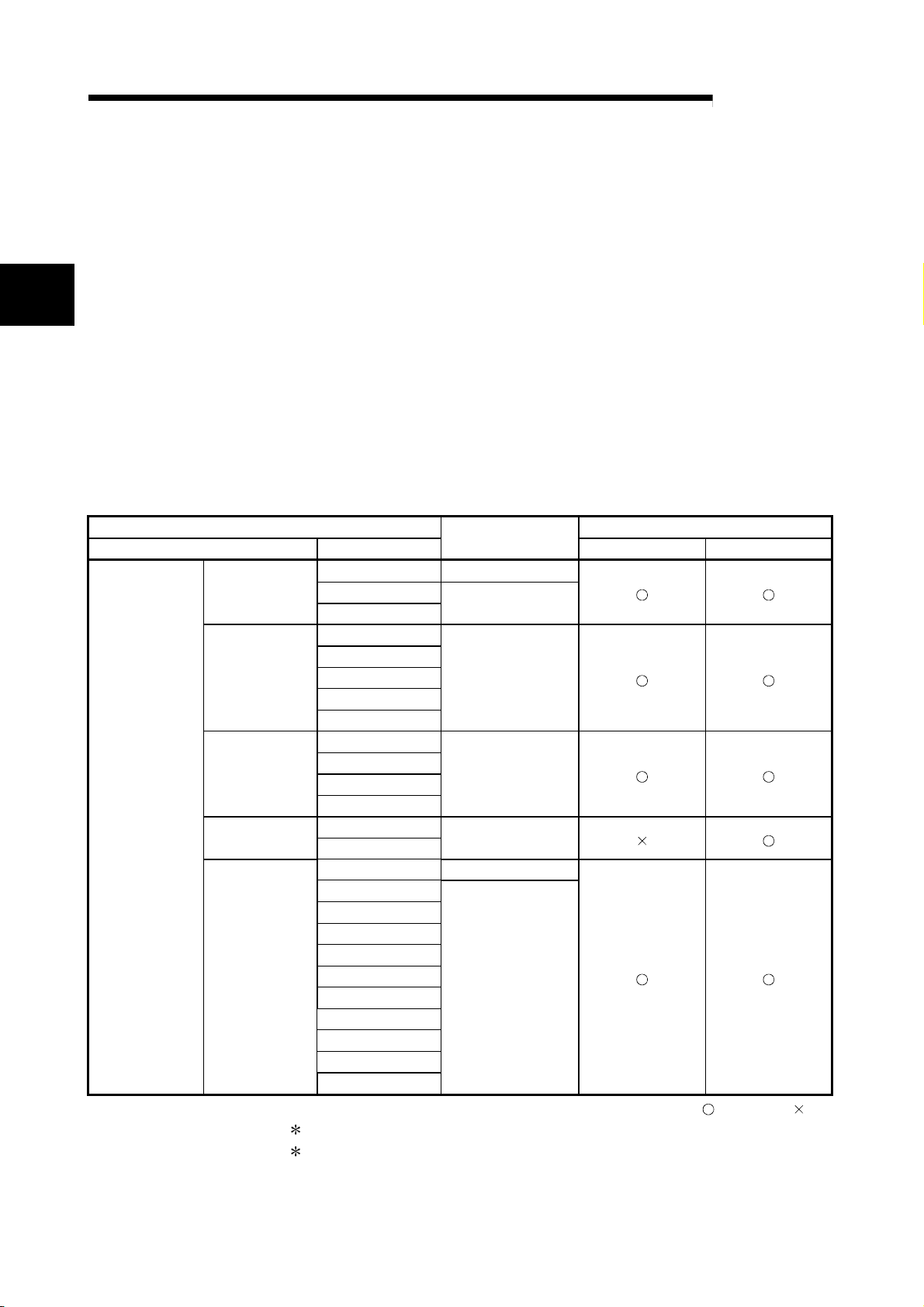
2.1 Applicable Systems
2
CPU type CPU model
Programmable
controller CPU
2 - 1 2 - 1
This chapter explains the system configuration of the QJ71MT91.
This section describes the applicable systems.
(1) Applicable modules and base units, and No. of modules
(a) When mounted with a CPU module
The table below shows the CPU modules and base units applicable to the
QJ71MT91 and quantities for each CPU model.
Depending on the combination with other modules or the number of
mounted modules, power supply capacity may be insufficient.
Pay attention to the power supply capacity before mounting modules, and if
the power supply capacity is insufficient, change the combination of the
modules.
Applicable CPU module
Basic model
QCPU
High
Performance
model QCPU
Process CPU
Redundant CPU
Universal model
QCPU
Q00JCPU Up to 8
Q00CPU
Q01CPU
Q02CPU
Q02HCPU
Q06HCPU
Q12HCPU
Q25HCPU
Q02PHCPU
Q06PHCPU
Q12PHCPU
Q25PHCPU
Q12PRHCPU
Q25PRHCPU
Q02UCPU Up to 36
Q03UDCPU
Q04UDHCPU
Q06UDHCPU
Q13UDHCPU
Q26UDHCPU
Q03UDECPU
Q04UDEHCPU
Q06UDEHCPU
Q13UDHCPU
Q26UDHCPU
1: Limited within the range of I/O points for the CPU module.
2: Can be installed to any I/O slot of a base unit.
No. of modules
Up to 24
Up to 64
Up to 64
Up to 53
Up to 64
*2
*1
Main base unit Extension base unit
Base unit
(Continued on next page)
: Applicable, : N/A
2 SYSTEM CONFIGURATION
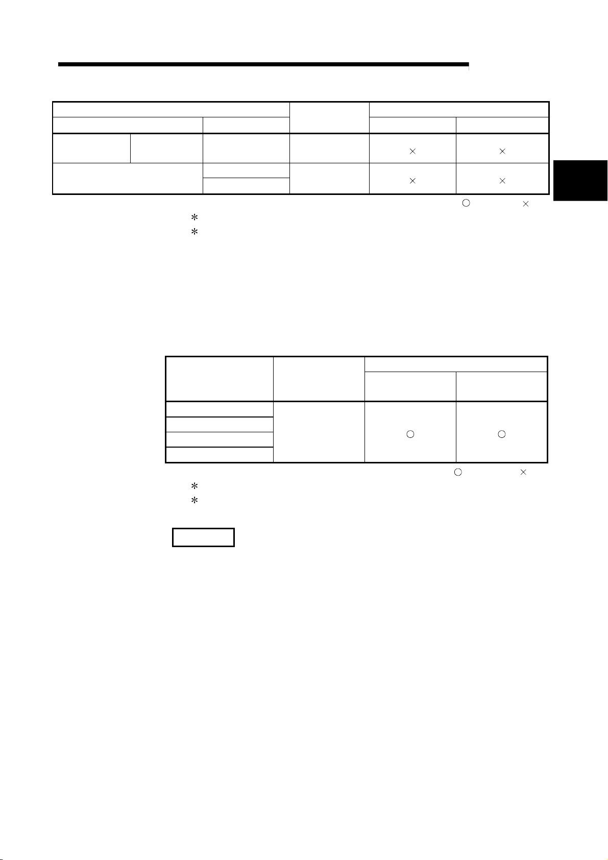
Applicable CPU module Base unit*2
CPU type CPU model
Programmable
controller CPU
C Controller module
Safety CPU QS001CPU N/A
Q06CCPU-V
Q06CCPU-V-B
1: Limited within the range of I/O points for the CPU module.
2: Can be installed to any I/O slot of a base unit.
(b) Mounting to a MELSECNET/H remote I/O station
The table below shows the network modules and base units applicable to
the QJ71MT91 and quantities for each network module model.
Depending on the combination with other modules or the number of
mounted modules, power supply capacity may be insufficient.
Pay attention to the power supply capacity before mounting modules, and if
the power supply capacity is insufficient, change the combination of the
Applicable network
module
QJ72LP25-25
QJ72LP25G
QJ72LP25GE
QJ72BR15
modules.
1: Limited within the range of I/O points for the network module.
2: Can be installed to any I/O slot of a base unit.
No. of modules
N/A
No. of modules*1
Up to 64
MELSEC-Q
*1
Main base unit Extension base unit
: Applicable, : N/A
Base unit*2
Main base unit of
remote I/O station
Extension base unit of
remote I/O station
: Applicable, : N/A
2
REMARK
The Basic model or C Controller module QCPU cannot create the MELSECNET/H
remote I/O network.
2 - 2 2 - 2
2 SYSTEM CONFIGURATION
(2) Support of the multiple CPU system
When using the QJ71MT91 in a multiple CPU system, refer to the QCPU User's
Manual (Multiple CPU System) first.
(a) Compatible QJ71MT91
The function version of the first released QJ71MT91 is B, and it supports
multiple CPU systems.
(b) Intelligent function module parameters
Write intelligent function module parameters to only the control CPU of the
QJ71MT91.
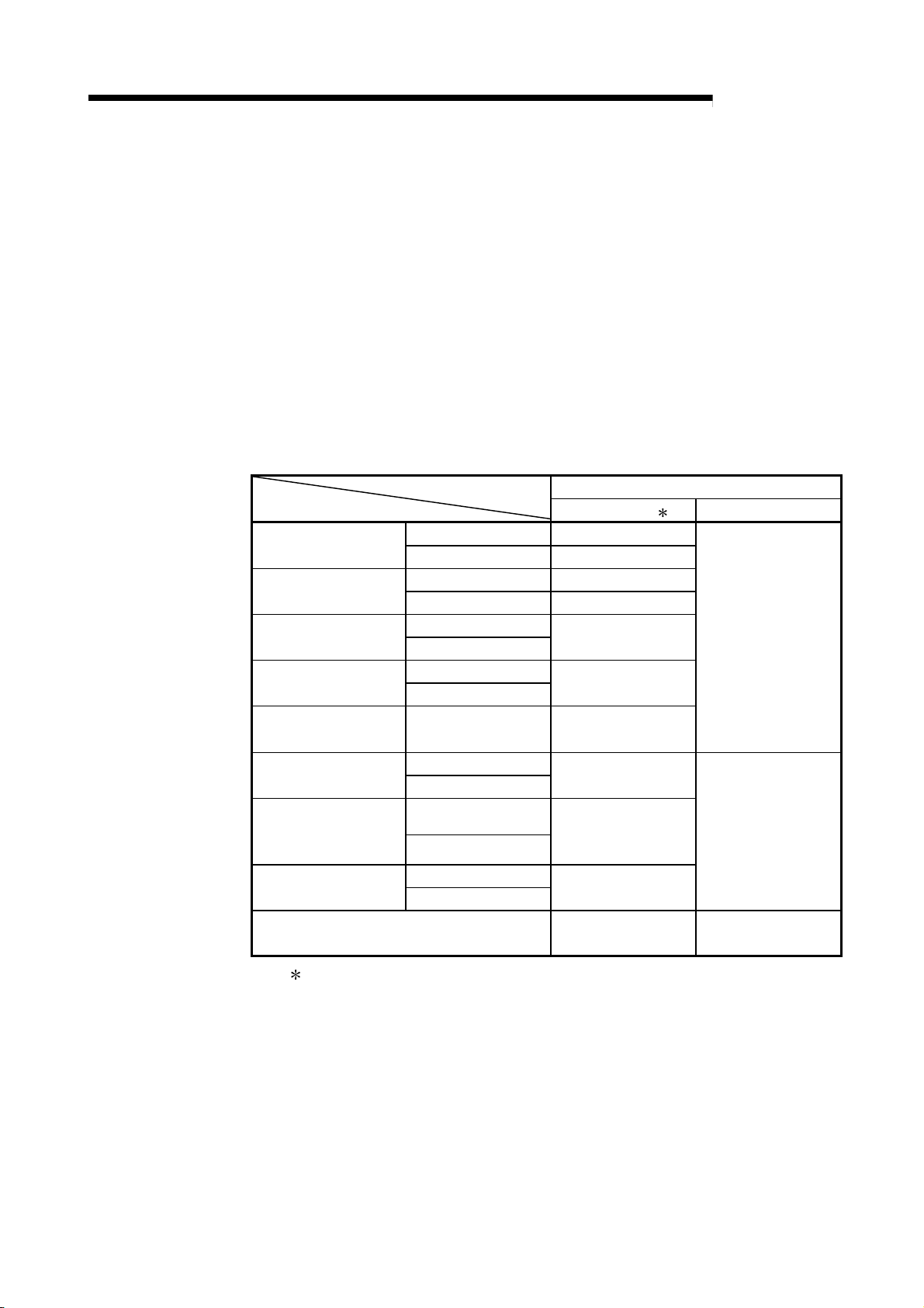
(3) Supported software packages
Relation between the system containing the QJ71MT91 and software package is
shown in the following table.
GX Developer is required to start up the system that uses the QJ71MT91.
Q00J/Q00/Q01CPU
Q12H/Q25HCPU
Q02PH/Q06PHCPU
Q12PH/Q25PHCPU
Software version
GX Developer 1 GX Configurator-MB
Single CPU system Version 7 or later
Multiple CPU system Version 8 or later
Single CPU system Version 4 or later Q02/Q02H/Q06H/
Multiple CPU system Version 6 or later
Single CPU system
Multiple CPU system
Single CPU system
Multiple CPU system
Version 8.68W or later
Version 7.10L or later
MELSEC-Q
Version 1.00A or later
Q12PRH/Q25PRHCPU Redundant system Version 8.45X or later
Q13UDH/Q26UDHCPU
Q03UDE/Q04UDEH/
Q06UDEH/Q13UDEH/
Q26UDEHCPU
Q06UDHCPU
When mounted to MELSECNET/H remote I/O
station
1: Refer to Section 2.3 for the accessible range of GX Developer.
Single CPU system
Multiple CPU system
Single CPU system
Multiple CPU system
Single CPU system Q02U/Q03UD/Q04UDH/
Multiple CPU system
Version 8.62Q or later
Version 8.68W or later
Version 8.48A or later
Version 6.01B or later Version 1.00A or later
Version 1.08J or later
2 - 3 2 - 3
2 SYSTEM CONFIGURATION
2.2 Devices Necessary for Network Configuration
This section explains the devices that configure a network.
Please note that the network must be installed by qualified networking specialists to
take sufficient safety measures.
The 10BASE-T or 100BASE-TX can be used to connect the QJ71MT91 to a network.
The QJ71MT91 will distinguish between 10BASE-T and 100BASE-TX, and between
the full duplex and half duplex communication mode according to the hub type.
However, for connection with the hub that does not have the auto negotiation function,
set the half duplex communication mode on the hub side.
1)
Hub (
Twisted pair cable
MELSEC-Q
Cascade connection is allowd for up to
*1
two stages when 100BASE-TX is used, or
up to four stages when 10BASE-T is used.
Target device
QJ71MT91
MODBUS /TCP slave device
R
MODBUS /TCP master device
Use the devices that comply with the IEEE802.3 100BASE-TX/10BASE-T Standard.
R
(1) Hub and other equipment
(a) Shielded twisted pair cable
1) For 100BASE-TX
Shielded twisted pair cable (STP cable), Category 5
2) For 10BASE-T
Unshielded twisted pair cable (UTP cable), Category 3 (4, 5)
A straight cable can be used.
(We do not guarantee proper operation if a crossing cable is used for the
100BASE-TX/10BASE-T connection between the QJ71MT91 and the
target device.)
(b) RJ45 jack
(c) Hub for 100Mbps/10Mbps network
POINT
In high-speed communication (100Mbps) by the 100BASE-TX connection, a
communication error may occur under the influence of high frequency noise from
devices other than the programmable controller in the installation environment.
Take the following action on the QJ71MT91 side to prevent the influence of high
frequency noise in the construction of a network system.
(1) Wiring connection
Do not install a twisted pain cable together with the main circuit and power
cables, etc.
Place the twisted pair cable in a duct.
(2) Communication system
Increase the number of communication retries if necessary.
Change the hub used for connection into a 10Mbps hub, and make
communication at a transmission speed of 10Mbps.
2 - 4 2 - 4
2 SYSTEM CONFIGURATION
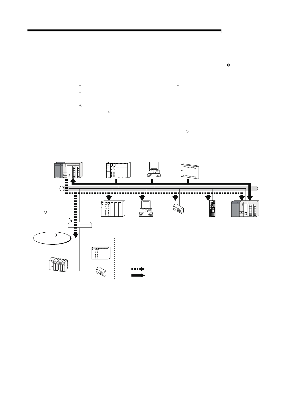
2.3 System Configuration and Access Range
This section provides the system configurations using the QJ71MT91. ( 1)
The target devices available for communication with the QJ71MT91 are the following
two kinds of devices.
Master/slave device supporting the MODBUSR/TCP protocol
Personal computer running GX Developer
1: Ethernet devices can also be installed on the Ethernet line where the
MODBUS
R
/TCP system exists. (However, communication with the QJ71MT91 is
not available.)
(1) Basic system configuration (MODBUSR/TCP communication)
Third party
QJ71MT91
[Master/slave function]
programmable
controller
[Master]
User application
[Master]
HMI
[Master]
MELSEC-Q
MODBUS /TCP
serial gateway device
R
MODBUS serial
slave device
R
MELSEC-A series
programmable controller
(AJ71UC24-S2)
Third party
programmable
controller
[Slave]
Third party
programmable controller
Remote I/O
User application
[Slave]
Accessible from QJ71MT91 (master function) to each slave
Accessible from each master to QJ71MT91 (slave function)
Remote I/O
[Slave]
CNC
[Slave]
Ethernet
QJ71MT91
[Slave function]
2 - 5 2 - 5
2 SYSTEM CONFIGURATION
(2) GX Developer connection
(a) Accessible range of GX Developer
Refer to Appendix 3 for the GX Developer connection setup examples.
[Access path via QJ71MT91]
MELSEC-Q
GX Developer
MODBUS /TCP
QJ71MT91
Connected
programmable
controller
R
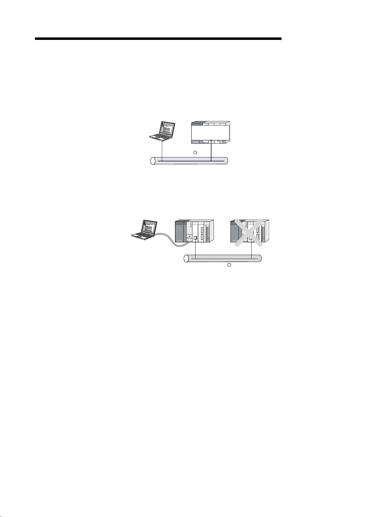
(b) Precautions for GX Developer connection
When the QJ71MT91 and Ethernet module exist together on the same
Ethernet, access cannot be made between the QJ71MT91 and Ethernet
module.
GX Developer
Ethernet module
Ethernet and MODBUS /TCP mixed network
QJ71MT91
R
2 - 6 2 - 6
2 SYSTEM CONFIGURATION
2.4 Precautions for System Configuration
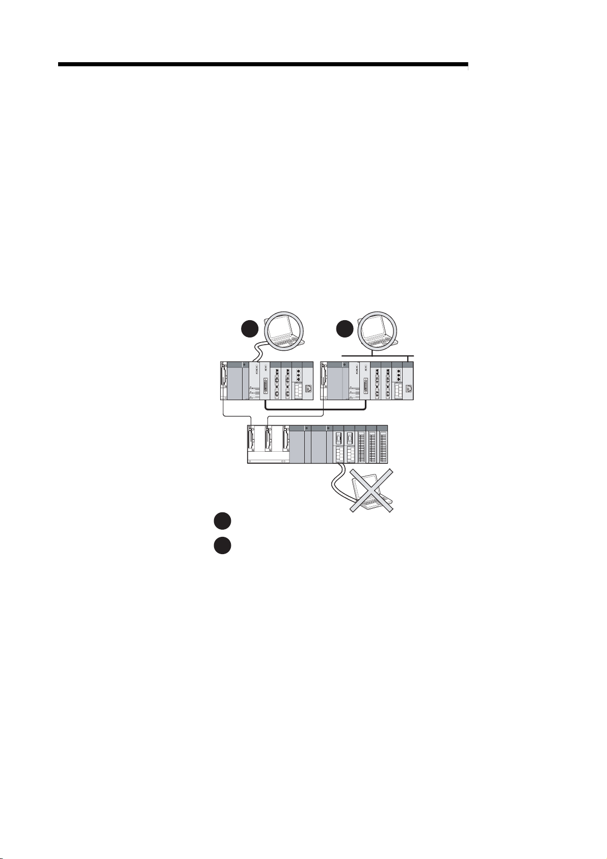
(1) For Use with Q12PRH/Q25PRHCPU
(a) About dedicated instructions
Dedicated instructions cannot be used.
Instead of the MBRW instruction, use the automatic communication
function. (Refer to Section 9.2 and 9.3.)
The MBREQ instruction cannot be used.
(b) GX Configurator-MB
GX Configurator-MB cannot be used when accessing the
Q12PRH/Q25PRHCPU via an intelligent function module on an extension
base unit from GX Developer.
Connect a personal computer with a communication path indicated below.
1 2
MELSEC-Q
Main base unit
Extension base unit
(GX Configurator-MB cannot be used.)
1
Direct connection to the CPU
2
Connection through an intelligent function module on the main base unit
(Through Ethernet module, MELSECNET/H module, or CC-Link module)
2 - 7 2 - 7

2 SYSTEM CONFIGURATION
2.5 How to Check the Function Version and Software Version
Confirm the function version of the QJ71MT91 and the software version of GX
Configurator-MB in the following methods.
(1) Checking the function version of the QJ71MT91
(a) Checking at "the SERIAL field of the rating plate" located on
the side of the module
The serial No. and function version of the module is shown in the SERIAL
field of the rating plate.
MELSEC-Q
MAC ADD.
Serial No.(first5 digits)
Function version
Relevant regulation standards
(b) Checking by GX Developer
The serial No. and function version of the module are displayed on the
"Production Info. List" and "Module's Detailed Information" screen of GX
Developer.
The following explains how to check them on the "Production Info. List"
screen.
(For the case of "Module’s Detailed Information", refer to Section 11.2.)
[Operating procedure]
[Diagnostics]
[System monitor] Product Inf. List
2 - 8 2 - 8
2 SYSTEM CONFIGURATION
[Serial No, Ver, and Product No.]
*1: The Production No. column display is active only when the CPU used is
POINT
The serial No. on the rating plate may be different from the serial No. displayed on
the product information screen of GX Developer.
The serial No. on the rating plate indicates the management information of the
product.
The serial No. displayed on the product information screen of GX Developer
indicates the function information of the product.
The function information of the product is updated when a new function is added.
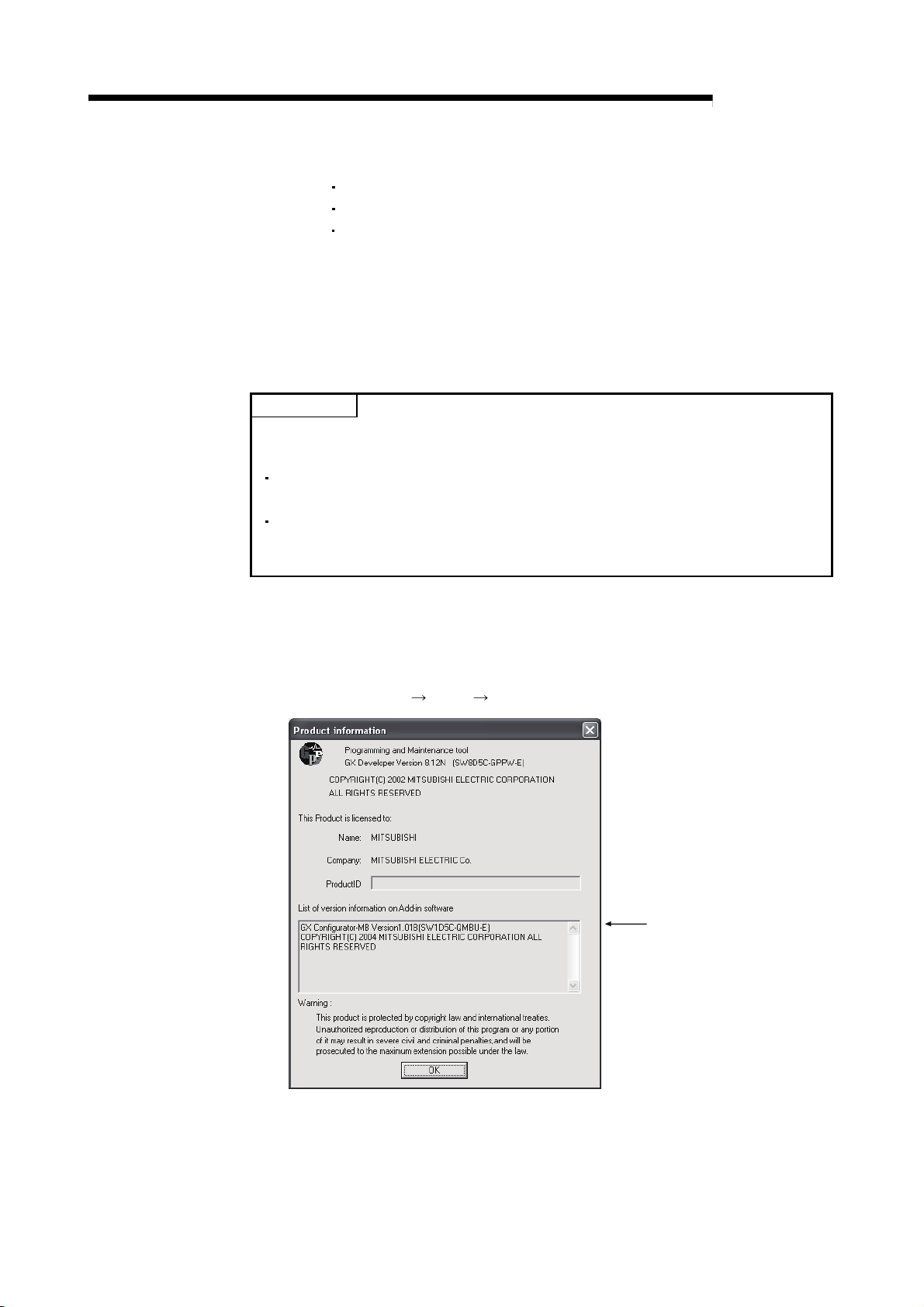
(2) Checking the software version of GX Configurator-MB
The software version of GX Configurator-MB can be checked in GX Developer’s
"Product information" screen.
[Operating procedure]
GX Developer
MELSEC-Q
Serial No. of the module is displayed in the Serial No. column.
Function version of the module is displayed in the Ver. column.
Serial No. printed on the rating plate is displayed in the Production No.
column. *1
Note that, because the QJ71MT91 does not support the production No.
display, "-" is displayed.
a Universal model QCPU.
[Help] [Product information]
Software version
2 - 9 2 - 9
 Loading...