

Mitsubishi Electronics QJ71LP21, QJ71LP21-25, QJ71LP21GE, QJ71LP21S-25, QJ72LP25-25 User Manual
...
Q Corresponding MELSECNET/H
Network System
Reference Manual (Remote I/O network)
-QJ71LP21
-QJ71LP21-25
-QJ71LP21S-25
-QJ71LP21G
-QJ71LP21GE
-QJ71BR11
-QJ72LP25-25
-QJ72LP25G
-QJ72LP25GE
-QJ72BR15

SAFETY PRECAUTIONS
(Read these precautions before using this product.)
Before using this product, please read this manual and the relevant manuals carefully and pay full
attention to safety to handle the product correctly.
The precautions given in this manual are concerned with this product only. For the safety precautions of
the programmable controller system, refer to the user’s manual for the CPU module used.
In this manual, the safety precautions are classified into two levels: "
WARNING
CAUTION
Under some circumstances, failure to observe the precautions given under "
serious consequences.
Observe the precautions of both levels because they are important for personal and system safety.
Make sure that the end users read this manual and then keep the manual in a safe place for future
reference.
Indicates that incorrect handling may cause hazardous conditions,
resulting in death or severe injury.
Indicates that incorrect handling may cause hazardous conditions,
resulting in minor or moderate injury or property damage.
[Design Precautions]
WARNING" and " CAUTION".
CAUTION" may lead to
!
WARNING
When the network develops a communication error, the station with the communication error will
enter into the following status.
Check the communication status information and configure an interlock circuit in the sequence
program to ensure that the entire system will operate safely. Failure to do so may result in an
accident due to an incorrect output or malfunction.
(1) The remote master station will hold the data from before the communication error.
(2) The remote I/O station turns off all outputs. The output module of the remote I/O station can
clear/hold the output status at the time of error by using the remote I/O module parameters.
As the parameters are set to "clear" by default, the output module turns off the outputs at the
time of error. If it is required to hold the output in order to operate the system safely, set the
parameters to "hold".
A - 1 A - 1
[Design Precautions]
!
WARNING
When connecting a peripheral with the programmable controller CPU or connecting a personal
computer with an intelligent function module to modify data of a running programmable
controller, configure an interlock circuit in the sequence program to ensure that the entire
system will always operate safely. For other forms of control (such as program modification or
operating status change) of a running programmable controller, read the relevant manuals
carefully and ensure that the operation is safe before proceeding. Especially, when a remote
programmable controller is controlled by an external device, immediate action cannot be taken if
a problem occurs in the programmable controller due to a communication failure. To prevent
this, configure an interlock circuit in the sequence program, and determine corrective actions to
be taken between the external device and CPU module in case of a communication failure.
If a communication cable is disconnected, the network may be unstable, resulting in a
communication failure of multiple stations. Configure an interlock circuit in the program to ensure
that the entire system will always operate safely even if communications fail. Failure to do so
may result in an accident due to an incorrect output or malfunction.
!
CAUTION
Do not install the control lines or communication cables together with the main circuit lines or
power cables. Keep a distance of 100mm (3.94 in.) or more between them. Failure to do so may
result in malfunction due to noise.
Reset the CPU module or remote I/O module after changing its parameters. Failure to do so
may cause malfunction because the previous parameter settings remain in the module.
[Installation Precautions]
!
CAUTION
Use the programmable controller in an environment that meets the general specifications in the
user’s manual for the CPU module used. Failure to do so may result in electric shock, fire,
malfunction, or damage to or deterioration of the product.
To mount the module, while pressing the module mounting lever located in the lower part of the
module, fully insert the module fixing projection(s) into the hole(s) in the base unit and press the
module until it snaps into place. Incorrect mounting may cause malfunction, failure or drop of the
module. When using the programmable controller in an environment of frequent vibrations, fix
the module with a screw.
Tighten the screws within the specified torque range. Undertightening can cause drop of the
screw, short circuit, or malfunction. Overtightening can damage the screw and/or module,
resulting in drop, short circuit, or malfunction
Shut off the external power supply (all phases) used in the system before mounting/removing a
module or connecting/disconnecting a connector. Failure to do so may result in damage to the
product. Modules can be replaced online on a remote I/O station where a remote I/O module
with function version D or later is used. Note that there are restrictions on the modules that can
be replaced online, and each module has its predetermined replacement procedure. For details,
refer to the relevant section in this manual.
A - 2 A - 2
[Installation Precautions]
!
CAUTION
Do not directly touch any conductive parts and electronic components of the module.
Doing so can cause malfunction or failure of the module.
[Wiring Precautions]
!
WARNING
Shut off the external power supply (all phases) used in the system before installation and wiring.
Failure to do so may result in electric shock or damage to the product.
[Wiring Precautions]
!
CAUTION
Individually ground the FG terminal of the programmable controller with a ground resistance of
100Ω or less.
Failure to do so may result in electric shock or malfunction.
Check the rated voltage and terminal layout before wiring to the module, and connect the cables
correctly. Connecting a power supply with a different voltage rating or incorrect wiring may
cause a fire or failure.
Connectors for external devices and coaxial cables must be crimped or pressed with the tool
specified by the manufacturer, or must be correctly soldered. Incomplete connections may
cause short circuit, fire, or malfunction.
Place the cables in a duct or clamp them. If not, dangling cable may swing or inadvertently be
pulled, resulting in damage to the module or cables or malfunction due to poor contact.
Tighten the terminal screws within the specified torque range. Undertightening can cause short
circuit, fire, or malfunction. Overtightening can damage the screw and/or module, resulting in
drop, short circuit, or malfunction.
When disconnecting the cable from the module, do not pull the cable by the cable part. For the
cable with connector, hold the connector part of the cable. For the cable connected to the
terminal block, loosen the terminal screw. Pulling the cable connected to the module may result
in malfunction or damage to the module or cable.
Prevent foreign matter such as dust or wire chips from entering the module. Such foreign matter
can cause a fire, failure, or malfunction.
A protective film is attached to the top of the module to prevent foreign matter, such as wire
chips, from entering the module during wiring.
Do not remove the film during wiring.
Remove it for heat dissipation before system operation.
Mitsubishi programmable controllers must be installed in control panels. Connect the main
power supply to the power supply module in the control panel through a relay terminal block.
Wiring and replacement of a power supply module must be performed by qualified maintenance
personnel with knowledge of protection against electric shock. For wiring methods, refer to the
QCPU User's Manual (Hardware Design, Maintenance and Inspection).
A - 3 A - 3
[Setup and Maintenance Precautions]
!
WARNING
Do not touch any terminal while power is on. Doing so will cause electric shock or malfunction.
Shut off the external power supply (all phases) used in the system before cleaning the module or
retightening the terminal screws or module mounting screws.
Failure to do so may result in electric shock or cause the module to fail or malfunction.
[Setup and Maintenance Precautions]
!
CAUTION
Before performing online operations (especially, program modification, forced output, and
operating status change) for the running CPU module on another station from GX Developer
over the MELSECNET/H network, read relevant manuals carefully and ensure the safety.
Improper operation may damage machines or cause accidents.
Do not disassemble or modify the modules.
Doing so may cause failure, malfunction, injury, or a fire.
Use any radio communication device such as a cellular phone or PHS (Personal Handy-phone
System) more than 25cm (9.85 inches) away in all directions from the programmable controller.
Failure to do so may cause malfunction.
Shut off the external power supply (all phases) used in the system before mounting/removing a
module or connecting/disconnecting a connector. Failure to do so may cause the module to fail
or malfunction. Modules can be replaced online in a remote I/O network system where a remote
I/O module with function version D or later is used. Note that there are restrictions on the
modules that can be replaced online, and each module has its predetermined replacement
procedure. For details, refer to the relevant section in this manual.
After the first use of the product, do not mount/remove the module to/from the base unit more
than 50 times (IEC 61131-2 compliant).
Exceeding the limit of 50 times may cause malfunction.
Before handling the module, touch a conducting object such as a grounded metal to discharge
the static electricity from the human body.
Failure to do so may cause the module to fail or malfunction.
[Disposal Precautions]
!
CAUTION
When disposing of this product, treat it as industrial waste.
A - 4 A - 4

CONDITIONS OF USE FOR THE PRODUCT
(1) Mitsubishi programmable controller ("the PRODUCT") shall be used in conditions;
i) where any problem, fault or failure occurring in the PRODUCT, if any, shall not lead to any major or
serious accident; and
ii) where the backup and fail-safe function are systematically or automatically provided outside of the
PRODUCT for the case of any problem, fault or failure occurring in the PRODUCT.
(2) The PRODUCT has been designed and manufactured for the purpose of being used in general
industries.
MITSUBISHI SHALL HAVE NO RESPONSIBILITY OR LIABILITY (INCLUDING, BUT NOT LIMITED
TO ANY AND ALL RESPONSIBILITY OR LIABILITY BASED ON CONTRACT, WARRANTY, TORT,
PRODUCT LIABILITY) FOR ANY INJURY OR DEATH TO PERSONS OR LOSS OR DAMAGE TO
PROPERTY CAUSED BY the PRODUCT THAT ARE OPERATED OR USED IN APPLICATION NOT
INTENDED OR EXCLUDED BY INSTRUCTIONS, PRECAUTIONS, OR WARNING CONTAINED IN
MITSUBISHI'S USER, INSTRUCTION AND/OR SAFETY MANUALS, TECHNICAL BULLETINS AND
GUIDELINES FOR the PRODUCT.
("Prohibited Application")
Prohibited Applications include, but not limited to, the use of the PRODUCT in;
Nuclear Power Plants and any other power plants operated by Power companies, and/or any other
cases in which the public could be affected if any problem or fault occurs in the PRODUCT.
Railway companies or Public service purposes, and/or any other cases in which establishment of a
special quality assurance system is required by the Purchaser or End User.
Aircraft or Aerospace, Medical applications, Train equipment, transport equipment such as Elevator
and Escalator, Incineration and Fuel devices, Vehicles, Manned transportation, Equipment for
Recreation and Amusement, and Safety devices, handling of Nuclear or Hazardous Materials or
Chemicals, Mining and Drilling, and/or other applications where there is a significant risk of injury to
the public or property.
Notwithstanding the above, restrictions Mitsubishi may in its sole discretion, authorize use of the
PRODUCT in one or more of the Prohibited Applications, provided that the usage of the PRODUCT is
limited only for the specific applications agreed to by Mitsubishi and provided further that no special
quality assurance or fail-safe, redundant or other safety features which exceed the general
specifications of the PRODUCTs are required. For details, please contact the Mitsubishi
representative in your region.
A - 5 A - 5
REVISIONS
The manual number is given on the bottom left of the back cover.
Print Date Manual Number Revision
Oct., 2000 SH (NA) -080124-A First printing
May., 2001 SH (NA) -080124-B
Model addition
QJ71LP21G, QJ72LP25G, QJ71LP21GE, QJ72LP25GE
Correction
Product Components, About The Generic Terms And Abbreviations,
Chapter 1, Section 1.2, 2.4, 3.1.1, 3.1.2, 3.2.1, 3.2.2, 3.3.2, 4.2.1, 4.2.2,
4.8.2, Chapter 5, Section 5.1.5, 5.2.1, 6.1.2, 6.2.1, 6.3, 6.4, 7.1.1, 7.8,
8.1, 8.1.1, 8.1.4, 8.3.1, 8.3.2, Appendix 2, 3, 4, 5, Index
Addition
Section 8.2.6
Apr., 2002 SH (NA) -080124-C
Correction
Section 1.2, 1.3, 2.3.1, 2.3.2, 2.3.3, 2.5, 3.1.1, 3.1.2, 3.2, 3.3.2, 4.2.1,
6.1.1, 6.4, Chapter 7, Section 8.4, Appendix 2, 3
Changed item numbers
Nov., 2002 SH (NA) -080124-D
Apr., 2003 SH (NA) -080124-E
Section 2.3
Addition
Section 2.4, Section 2.4 Section 2.5
Section 7.10
Model addition
QJ71LP21S-25
Correction
SAFETY PRECAUTIONS, CONTENTS,
Generic Terms And Abbreviations, Product Components,
Section 1.1, 1.2, 3.1.1, 3.1.2, 4.1.2, 4.8.1, 4.8.2, 7.1.1, 8.1.4,
Appendix 2, 3
Correction
SAFETY PRECAUTIONS, About Manuals, Section 1.2, 2.1.2, 2.2.2,
2.3.2, 2.5, 3.1.1, 3.1.2, 3.2.2, 3.3.1, Chapter 5, Section 5.1.3, 5.1.5, 6.2,
6.3, 6.4, 6.5, 8.1, 8.2, 8.2.1, 8.2.5, 8.3.1
A - 6 A - 6
The manual number is given on the bottom left of the back cover.
Print Date Manual Number Revision
Jun., 2004 SH (NA) -080124-F
Correction
SAFETY PRECAUTIONS, Manuals, Generic Terms And Abbreviations,
Section 1.2, 2.1.2, 2.2.2, 2.3.2, 2.4.2, 2.5, 3.1.1, 3.1.2, 3.1.3, 3.1.4, 3.2,
3.2.2, 4.2.2, 4.9.1, 4.10, 4.10.1, 4.10.2, 4.10.3, Chapter 5, Section 5.1.1,
5.2, 5.2.1, 6.4, 6.5, Chapter 7, Section 8.1, 8.1.1, 8.1.2, 8.1.3, 8.1.4,
8.2.1, 8.2.3, 8.2.5, 8.2.7, 8.3.1, 8.3.2, Appendix 2, 3
Addition
Section 1.4, 2.4, 2.7, 3.3.3, 3.3.4, 7.11, 7.12, 8.2.7, Appendix 7
Changed section No.
Mar., 2005 SH (NA) -080124-G
Sep., 2005 SH (NA) -080124-H
May, 2006 SH (NA) -080124-I
Sep., 2006 SH (NA) -080124-J
Section 2.4
Correction
Section 2.5, Section 2.5 Section 2.6
Safety Precautions, Conformation to the EMC Directive and Low Voltage
Instruction, Product Configuration, Section 1.1, 1.2, 2.6, 2.7, 3.1.1, 3.1.2,
3.1.4, 3.2.2, 3.3.2, 4.2.1, 4.2.2, 4.3, 4.4, 4.8.1, 4.8.2, 4.9.1, 4.10.1, 5.1.4,
6.1.1, 6.2, 6.2.2, 6.3, 7.4, 8.1, 8.1.2, 8.1.3, 8.2, 8.2.1, 8.3.1, 8.3.2,
Appendix 2, 3, 4, 5, 7
Addition
Section 8.2.8
Correction
Generic Terms And Abbreviations, Section 1.2, Section 2.5, Section 3.2,
3.2.2, 3.3.2, Section 5.1.5, 5.2.1, Section 6.3, 6.5, Section 7.12, Section
8.2, 8.2.5, 8.3.1, 8.3.2, Appendix 3, 4, 5
Correction
Generic Terms And Abbreviations, Section 1.1, Chapter 2, Section 2.2.1,
2.5, 3.1.1, 3.1.4, 4.2.1, 4.2.2, 5.1.3, 5.1.4, 5.1.5, 6.3, 6.4, 7.1.1, 8.1.2,
8.3.2, Appendix 5
Addition
Section 2.5.1, 2.5.2
Correction
Section 2.1.2, 2.2.2, 2.3.2, 2.4.2, 4.2.1, 4.2.2, 8.3.2
A - 7 A - 7
The manual number is given on the bottom left of the back cover.
Print Date Manual Number Revision
Nov., 2006 SH (NA) -080124-K
Addition
SAFETY PRECAUTIONS
Correction
Section 2.5.2, 3.2.2, 4.2.1, 4.2.2, 4.3, 4.8.1, 4.8.2, 5.1.5, 8.1.2, 8.2, 8.2.4,
8.3.2, Appendix 2, 3, 5
Sections added
Section 8.2.8, 8.4, 8.5
Changed section No.
Section 8.2.8
Oct., 2007 SH (NA) -080124-L
Addition
Chapter 1, Section 2.1.2, 2.2.2, 2.3.2, 2.4.2, 2.5.1, 2.5.2, 2.7, 3.3.1, 3.3.2,
4.8.2, Chapter 5, Section 5.1.4, 5.1.5, 8.2.1, 8.3.1, Appendix 2, 4, 5
Correction
SAFETY PRECAUTIONS , Generic Terms And Abbreviations, Section
2.2.1, 2.3.1, 2.4.1, 4.2.1, 4.7.1, 4.7.2, 4.7.3, 4.9.1, 5.1.1, 5.1.3, 6.1.1, 6.2,
6.3, 6.5, 6.6, 7.1.1, 7.12, 8.1, Appendix 3
Sections added
DEFINITIONS OF TERMINOLOGY, Section 6.4
Changed section No.
Section 6.4 to 6.5
Feb., 2008 SH (NA)-080124-M
Correction
Generic Terms And Abbreviations, Section 1.2, 2.1.2, 2.2.2, 2.3.2, 2.4.2,
2.5, 3.2.2, 3.3.2, 4.7, 4.8, 4.9.1, 5.1.1, 5.1.4 to 5.1.6, 5.2.1, 6.1.1, 6.5, 6.6,
7.1.1, 7.8, 7.11.4, 8.1, 8.3, 8.4, Appendix 2, 3, 5
Sep., 2008 SH (NA)-080124-N
Correction
SAFETY PRECAUTIONS, Compliance with the EMC and Low Voltage
Directives, Generic Terms And Abbreviations, DEFINITIONS OF
TERMINOLOGY, Chapter1, Section 1.2, 1.3, 2.1.2, 2.1.3, 2.2, 2.2.1,
2.2.3, 2.3, 2.4.2, 2.4.3, 2.5.1, 2.6, 3.1.4, 3.2, 3.3.2, 3.3.4, 4.2.1, 4.2.2, 4.8,
4.9.1, Chapter 5, Section 5.1.3 to 5.1.5, 6.1.2, 6.5, 6.6, Chapter 7, 7.1.1,
7.10, 7.11, 7.11.1, 7.11.3, 7.11.4, Chapter 8, 8.1, 8.2, 8.2.5, 8.2.7, 8.3.1,
8.3.2, Appendix 2 to 6
Section 8.2.9, Section 8.4 Section 8.6
Section 6.5 to 6.6, Appendix 7 Appendix 6
A - 8 A - 8
The manual number is given on the bottom left of the back cover.
Print Date Manual Number Revision
Aug., 2009 SH (NA) -080124-O
Correction
Generic Terms And Abbreviations, Section 1.3, 2.5.1, 2.7, 3.3.2, 6.4.2,
Chapter 8
Sections added
Section 8.3.1
Changed section No.
Sep., 2010 SH (NA) -080124-P
Mar., 2011 SH (NA) -080124-Q
Sep.,2012 SH (NA) -080124-R
Section 8.3.1(4)
Correction
Section 8.3.2, Section 8.3.2 Section 8.3.3
Generic Terms And Abbreviations, Section 1.3, 2.5.1, 2.5.2, 2.7, 3.3.2,
4.2.1, 4.2.2, 4.3, Chapter 5, Section 5.1.5, 5.1.6, 6.1.1, 8.2.9, 8.3.1, 8.3.2,
8.3.3, Appendix 2, 6
Sections added
CONDITIONS OF USE FOR THE PRODUCT
Correction
Section 3.1.4, 3.3.1, 8.3.2, Appendix 5
Correction
SAFETY PRECAUTIONS, COMPLIANCE WITH THE EMC AND LOW
VOLTAGE DIRECTIVES, GENERIC TERMS AND ABBREVIATIONS,
PACKING LIST, Section 1.2, 1.4, 2.1.2, 2.2.2, 2.3.1, 2.3.2, 2.4.1, 2.4.2,
2.5.1, 2.5.2, 2.6, 2.7, 3.1.1, 3.1.2, 3.1.4, 3.2, 3.2.1, 3.2.2, 3.3.1, 3.3.2,
3.3.3, 3.3.4, 4.1, 4.2.1, 4.2.2, 4.3, 4.7, 4.8.1, 4.8.2, 4.9.1, 4.10, 4.10.1,
4.10.2, 4.10.3, Chapter 5, Section 5.1.1, 5.1.2, 5.1.3, 5.1.4, 5.1.5, 5.1.6,
5.2.1, 6.1.1, 6.1.2, 6.5, 6.6, Chapter 7, Section 7.11, 7.11.3, 7.11.4, 7.12,
Chapter 8, Section 8.1, 8.1.1, 8.1.3, 8.2, 8.2.1, 8.2.4, 8.2.5, 8.3, 8.3.1,
8.3.2, 8.3.3, 8.4, 8.6, Appendix 1, 2, 3, 5, 6, INDEX
Jul., 2013 SH (NA) -080124-S
Correction
SAFETY PRECAUTIONS, MANUALS, GENERIC TERMS AND
ABBREVIATIONS, Chapter 1, Section 1.2, 1.3, 2.5.1, 2.5.2, 4.2.1, 4.2.2,
4.7, 4.7.1, 4.7.2, 4.7.3, 4.8.1, 4.10.1, 4.10.2, 4.10.3, 4.10.4, Chapter 5,
Section 5.2.1, 6.1.1, 6.4.1, 6.6, 7.11, 7.12, 8.1.1, 8.1.2, 8.1.3, 8.1.4, 8.2.6,
8.3.1, 8.3.3, Appendix 1, 2, 3, 4, 5
Japanese Manual Version SH-080123-W
This manual confers no industrial property rights or any rights of any other kind, nor does it confer any patent
licenses. Mitsubishi Electric Corporation cannot be held responsible for any problems involving industrial property
rights which may occur as a result of using the contents noted in this manual.
2000 MITSUBISHI ELECTRIC CORPORATION
A - 9 A - 9

INTRODUCTION
Thank you for purchasing the Mitsubishi MELSEC-Q series programmable controllers.
Before using this product, please read this manual carefully and develop familiarity with the functions and
performance of the MELSEC-Q series programmable controller to handle the product correctly.
CONTENTS
SAFETY PRECAUTIONS .............................................................................................................................. A- 1
CONDITIONS OF USE FOR THE PRODUCT ............................................................................................. A- 5
REVISIONS ................................................................................................................................................... A- 6
CONTENTS ................................................................................................................................................... A-10
MANUALS ................................................................................................................................................... A-15
COMPLIANCE WITH THE EMC AND LOW VOLTAGE DIRECTIVES ....................................................... A-15
GENERIC TERMS AND ABBREVIATIONS ................................................................................................. A-16
DEFINITIONS OF TERMINOLOGY .............................................................................................................. A-18
PACKING LIST ............................................................................................................................................... A-19
1 OVERVIEW 1- 1 to 1-11
1.1 Overview.................................................................................................................................................. 1- 2
1.2 Features .................................................................................................................................................. 1- 3
1.3 Abbreviations Used in the Text, Tables and Diagrams of This Manual ................................................ 1-10
1.4 Functions Added/Changed with Upgrade to Function Version D.......................................................... 1-11
2 SYSTEM CONFIGURATION 2- 1 to 2-23
2.1 Single Remote I/O Networks .................................................................................................................. 2- 1
2.1.1 Configuration .................................................................................................................................... 2- 1
2.1.2 Setting items ..................................................................................................................................... 2- 2
2.1.3 Available device ranges ................................................................................................................... 2- 3
2.2 Multiple Remote I/O Network (Process CPU) ........................................................................................ 2- 4
2.2.1 Configuration .................................................................................................................................... 2- 4
2.2.2 Setting items ..................................................................................................................................... 2- 5
2.2.3 Available device ranges ................................................................................................................... 2- 6
2.3 Multiplexed Remote I/O Network for Redundant System (Redundant CPU) ....................................... 2- 7
2.3.1 Configuration .................................................................................................................................... 2- 7
2.3.2 Setting items ..................................................................................................................................... 2- 8
2.3.3 Available device ranges ................................................................................................................... 2- 9
2.4 Multiple Remote I/O Network .................................................................................................................. 2-10
2.4.1 Configuration .................................................................................................................................... 2-10
2.4.2 Setting items ..................................................................................................................................... 2-11
2.4.3 Available device ranges ................................................................................................................... 2-12
2.5 Applicable Systems ................................................................................................................................. 2-13
2.5.1 Applicable systems for remote master stations ............................................................................... 2-13
2.5.2 Applicable systems for remote I/O stations ...................................................................................... 2-15
2.6 When Using a Multiple CPU System ...................................................................................................... 2-19
2.7 Checking Function Version and Serial No. ............................................................................................ 2-22
A - 10 A - 10

3 SPECIFICATIONS 3- 1 to 3-64
3.1 Performance Specifications .................................................................................................................... 3- 1
3.1.1 Optical loop system performance specifications ............................................................................. 3- 1
3.1.2 Coaxial cable system performance specifications .......................................................................... 3- 3
3.1.3 Optical fiber cable specifications ..................................................................................................... 3- 4
3.1.4 Coaxial cable specifications ............................................................................................................. 3- 5
3.2 Function Specifications ........................................................................................................................... 3-10
3.2.1 Cyclic transmission function (periodic communication) .................................................................. 3-11
(1) Communicating with I/O modules ................................................................................................... 3-11
(2) Communicating with intelligent function modules ........................................................................... 3-12
3.2.2 RAS functions ................................................................................................................................... 3-17
(1) Output reset function for communication errors ............................................................................. 3-17
(2) Hardware error time CPU operation mode setting ......................................................................... 3-17
(3) Automatic return function ................................................................................................................. 3-18
(4) Loopback function (optical loop system) ......................................................................................... 3-19
(5) Station detach function (coaxial bus system) ................................................................................. 3-21
(6) Transient transmission enabled even at CPU module error .......................................................... 3-22
(7) Abnormal detection time .................................................................................................................. 3-23
(8) Diagnostic function .......................................................................................................................... 3-24
(9) Redundant power supply on a remote I/O station .......................................................................... 3-25
(10) Online module change on a remote I/O station ............................................................................ 3-28
3.3 Link Data Send/Receive Processing Time Specifications ..................................................................... 3-34
3.3.1 Link data send/receive processing .................................................................................................. 3-34
3.3.2 Transmission delay time .................................................................................................................. 3-40
3.3.3 Switching time from the multiplexed remote master station to the multiplexed remote
sub-master station in a multiplexed remote I/O network ................................................................ 3-59
3.3.4 Output holding time during system switching in the multiplexed remote I/O network for
redundant system ............................................................................................................................ 3-60
4 SETTING AND PROCEDURE BEFORE OPERATION 4- 1 to 4-37
4.1 Procedure Before Operation ................................................................................................................... 4- 1
4.2 Part Names and Settings ........................................................................................................................ 4- 2
4.2.1 QJ71LP21, QJ71LP21-25, QJ71LP21G, QJ71LP21GE, QJ71BR11 (Remote master station)
......................................................................................................................................................... 4- 2
4.2.2 QJ72LP25-25, QJ72LP25G, QJ72LP25GE, QJ72BR15 ............................................................... 4- 6
4.3 Installing and Uninstalling the Module .................................................................................................... 4-11
4.4 Stopping the CPU (Unintentional Output Prevention) ........................................................................... 4-13
4.5 Checking the Input Power Supply Voltage ............................................................................................. 4-13
4.6 Powering On............................................................................................................................................ 4-13
4.6.1 Checking the on status of the POWER LED of the power supply module .................................... 4-13
4.6.2 Checking the on status of the RUN LED of the network module ................................................... 4-13
4.7 Unit Tests of the Network Module (Offline Test) .................................................................................... 4-14
4.7.1 Self-loopback test ............................................................................................................................. 4-15
4.7.2 Internal self-loopback test ................................................................................................................ 4-17
4.7.3 Hardware test ................................................................................................................................... 4-19
4.8 Cable Connections .................................................................................................................................. 4-21
4.8.1 Optical loop system .......................................................................................................................... 4-21
A - 11 A - 11

4.8.2 Coaxial bus system .......................................................................................................................... 4-23
4.9 Offline Tests from GX Developer ........................................................................................................... 4-28
4.9.1 Forward loop/reverse loop test (Remote master station only) ....................................................... 4-28
4.10 Network Diagnostics from GX Developer (Online Tests) .................................................................... 4-32
4.10.1 Loop test (optical loop system only) .............................................................................................. 4-33
4.10.2 Setup confirmation test .................................................................................................................. 4-34
4.10.3 Station order check test (optical loop system only) ...................................................................... 4-35
4.10.4 Communication test ....................................................................................................................... 4-36
5 PARAMETER SETTINGS 5- 1 to 5-38
5.1 Remote Master Station Parameter Setting ............................................................................................ 5- 5
5.1.1 Setting the number of modules (Network type) .............................................................................. 5- 5
5.1.2 Network settings ............................................................................................................................... 5- 6
(1) Starting I/O No. ................................................................................................................................ 5- 6
(2) Network No. ..................................................................................................................................... 5- 6
(3) Total stations .................................................................................................................................... 5- 6
(4) Group No. (Available for multiplexed remote master/sub-master station only) ............................... 5- 7
(5) Mode ................................................................................................................................................ 5- 7
(6) Parameter setting example ............................................................................................................. 5- 8
5.1.3 Common parameter ......................................................................................................................... 5- 9
(1) LX/LY setting .................................................................................................................................... 5- 9
(2) LB/LW setting ................................................................................................................................... 5-12
(3) Reserved station specification ......................................................................................................... 5-13
(4) Remote sub-master station ............................................................................................................. 5-13
5.1.4 Supplementary settings ................................................................................................................... 5-15
5.1.5 Refresh parameters ......................................................................................................................... 5-19
5.1.6 Valid Module During Other Station Access ..................................................................................... 5-31
5.1.7 Redundant settings .......................................................................................................................... 5-32
5.2 Remote I/O Station Parameter Settings ................................................................................................. 5-33
5.2.1 Remote I/O station possible parameter settings ............................................................................. 5-33
6 PROGRAMMING 6- 1 to 6-41
6.1 Programming Precautions ...................................................................................................................... 6- 1
6.1.1 Interlock related signals ................................................................................................................... 6- 1
6.1.2 Program example ............................................................................................................................. 6- 4
6.2 Cyclic Transmission ................................................................................................................................ 6- 7
6.2.1 32-bit data guarantee ....................................................................................................................... 6- 7
6.2.2 Block guarantee of cyclic data per station ....................................................................................... 6- 8
6.3 Communications with I/O Modules ......................................................................................................... 6- 9
6.4 Communications with Intelligent Function Modules ............................................................................... 6-10
6.4.1 Program example when using GX Configurator ............................................................................. 6-11
6.4.2 Program example when not using GX Configurator ....................................................................... 6-15
6.5 Link Dedicated Instruction List ................................................................................................................ 6-18
6.6 Using the Link Special Relays (SB)/ Link Special Registers (SW) ....................................................... 6-23
A - 12 A - 12

7 APPLICATION FUNCTIONS 7- 1 to 7-44
7.1 Transient Transmission Function (Non-Periodical Communication) ..................................................... 7- 2
7.1.1 Link Dedicated instruction ................................................................................................................ 7- 3
(1) Reading/writing remote I/O station intelligent function module buffer memory
(Z(P).REMFR/ Z(P).REMTO)........................................................................................................... 7- 3
7.2 Remote I/O Station System Monitor ....................................................................................................... 7- 9
7.3 Device Test for Remote I/O Station ........................................................................................................ 7-10
7.4 Multiplex Transmission Function (Optical Loop System) ...................................................................... 7-12
7.5 Return Sequence Station Number Setting Function.............................................................................. 7-13
7.6 Reserved Station Function ..................................................................................................................... 7-13
7.7 Interrupt Settings ..................................................................................................................................... 7-14
7.8 I/O Assignment Function ........................................................................................................................ 7-15
7.9 Stopping/Restarting the Cyclic Transmission and Stopping Link Refreshing (Network Test) ............. 7-16
7.10 Multiplexed remote master function (Process CPU)............................................................................ 7-17
7.11 Multiplexed remote master function for the redundant system (Redundant CPU) ............................. 7-32
7.11.1 Backup function of master operation on system switching between control system and
standby system ................................................................................................................................ 7-34
7.11.2 Master operation by the station that has started up as the control system.................................. 7-35
7.11.3 System switching request function of control system ................................................................... 7-36
7.11.4 Access function by specifying the control system or standby system ......................................... 7-39
7.12 Remote password ................................................................................................................................. 7-40
8 TROUBLESHOOTING 8- 1 to 8-61
8.1 Network Diagnostics (Network Monitor) ................................................................................................. 8- 2
8.1.1 Host information ............................................................................................................................... 8- 5
8.1.2 Other station information.................................................................................................................. 8- 7
8.1.3 Network monitor details ................................................................................................................... 8- 9
8.1.4 Error history monitor ......................................................................................................................... 8-12
8.2 Troubleshooting ...................................................................................................................................... 8-15
8.2.1 Items checked first ........................................................................................................................... 8-21
8.2.2 Items checked when data link cannot be performed throughout the system ................................ 8-21
8.2.3 Items checked when data link is disabled by resetting or powering off a station .......................... 8-22
8.2.4 Items checked when data link cannot be performed on a certain station ..................................... 8-22
8.2.5 Items checked when an communication data error is detected .................................................... 8-23
8.2.6 Items checked when a link dedicated instruction does not complete ............................................ 8-23
8.2.7 Items checked when multiplexed remote I/O network for redundant system does not operate
normally ........................................................................................................................................... 8-24
8.2.8 Items checked when a minor error (continue error) on a remote I/O station cannot be detected
......................................................................................................................................................... 8-24
8.2.9 Checking incorrect optical fiber cable connection during online .................................................... 8-25
8.3 Error Codes ............................................................................................................................................. 8-28
8.3.1 How to check error codes ................................................................................................................ 8-28
8.3.2 MELSECNET/H error code list ........................................................................................................ 8-34
8.3.3 Error codes detected on remote I/O stations and equivalent to CPU module error codes ........... 8-43
8.4 Canceling a Minor Error (Continue Error) on a Remote I/O Station ...................................................... 8-52
8.4.1 Canceling a specific remote I/O station error .................................................................................. 8-53
8.4.2 Canceling errors of all remote I/O stations ...................................................................................... 8-54
A - 13 A - 13

8.5 Procedure for Replacing a Normally Operating Redundant Power Supply Module ............................. 8-59
8.6 H/W Information ...................................................................................................................................... 8-60
APPENDICES App- 1 to App-53
Appendix 1 Precautions for Replacing MELSECNET/10 Remote I/O Network with MELSECNET/H
Remote I/O Network. .............................................................................................................App- 1
Appendix 2 Link Special Relay (SB) .........................................................................................................App- 3
Appendix 3 Link Special Register (SW) .................................................................................................. App-14
Appendix 4 Special Relay (SM) for Remote I/O Stations ....................................................................... App-33
Appendix 5 Special Register (SD) for Remote I/O Module .................................................................... App-36
Appendix 6 External Dimensions ............................................................................................................. App-50
INDEX Index- 1 to Index- 2
A - 14 A - 14

MANUALS
Relevant manuals
The manuals related to this product are listed below.
Order each manual as needed, referring to the following lists.
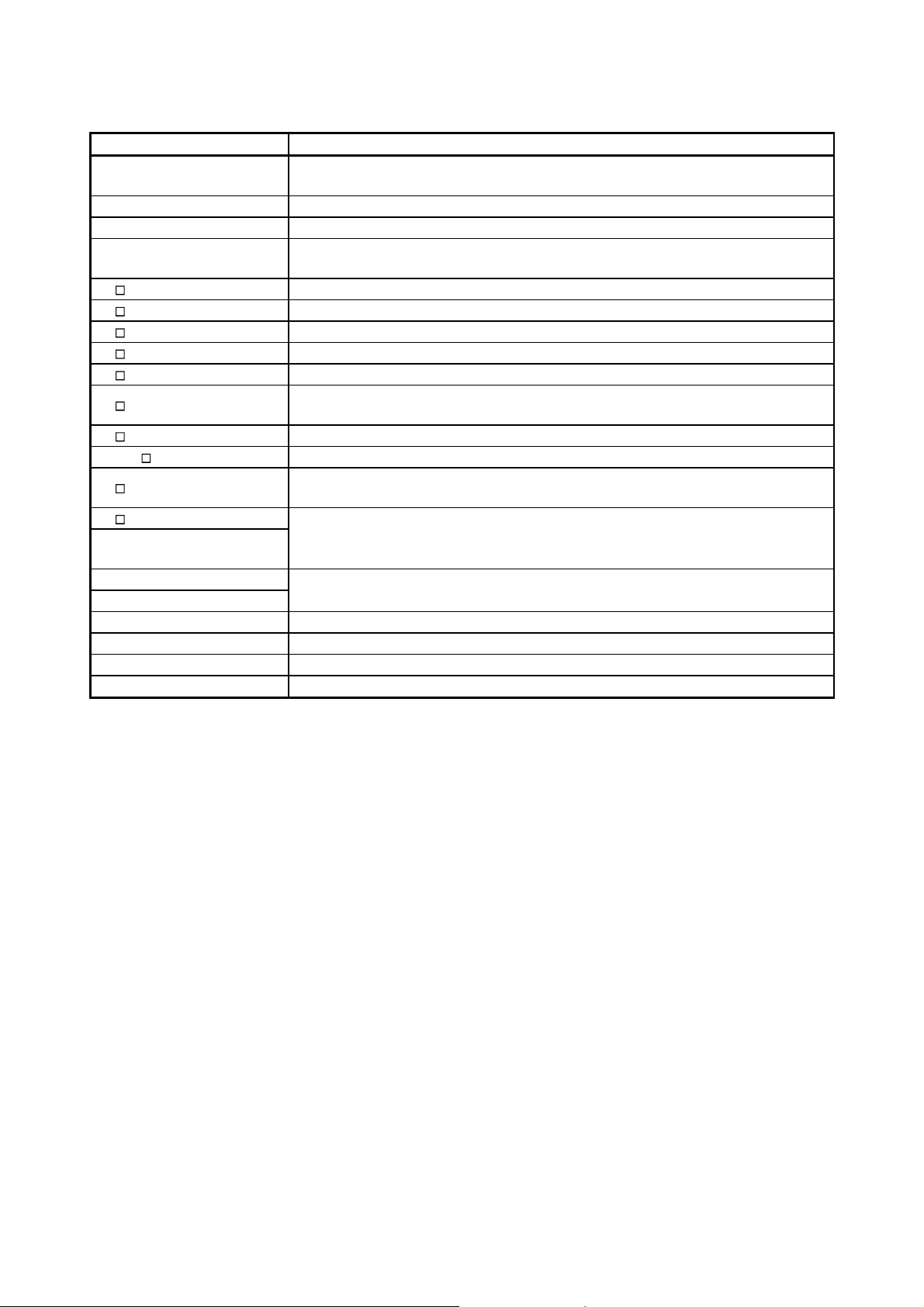
Manual name
Manual number
(model code)
Q Corresponding MELSECNET/H Network System Reference Manual (PLC to PLC network)
Specifications, procedures and settings before system operation, parameter setting, programming, and
troubleshooting of a MELSECNET/H network system (PLC to PLC network) (Sold separately)
Q Corresponding MELSECNET/H Remote I/O Module Reference Manual (MELSECNET/10
Mode)
Operating procedures, system configuration, parameter settings, functions, programming, and
troubleshooting of the MELSECNET/H remote I/O module when used in MELSECNET/10 mode.
(Sold separately)
COMPLIANCE WITH THE EMC AND LOW VOLTAGE DIRECTIVES
(1) For programmable controller system
To ensure that Mitsubishi programmable controllers maintain EMC and Low
Voltage Directives when incorporated into other machinery or equipment, certain
measures may be necessary. Please refer to one of the following manuals.
• QCPU User's Manual (Hardware Design, Maintenance and Inspection)
• Safety Guidelines
(This manual is included with the CPU module or base unit.)
The CE mark on the side of the programmable controller indicates compliance
with EMC and Low Voltage Directives.
(2) For the product
To ensure that this product maintains EMC and Low Voltage Directives, please
refer to one of the manuals listed under (1).
SH-080049
(13JF92)
SH-081164ENG
(13JV30)
A - 15 A - 15

GENERIC TERMS AND ABBREVIATIONS
Generic term/abbreviation Description
The abbreviation for the QJ71LP21, QJ71LP21-25, QJ71LP21S-25, QJ71LP21G,
QJ71LP21
QJ71BR11 The abbreviation for the QJ71BR11 MELSECNET/H network module
QJ72LP25
QJ72BR15 The abbreviation for the QJ72BR15 MELSECNET/H network module
Master module A generic term for the QJ71LP21 and QJ71BR11
Remote I/O module A generic term for the QJ72LP25 and QJ72BR15
Network module A generic term for master module and remote I/O module
Ethernet module
Serial communication module
CC-Link IE Controller Network
module
CC-Link IE Field Network The abbreviation for the QJ71GF11-T2 CC-Link IE Field Network module
MELSECNET/H The abbreviation for the Q series MELSECNET/H network system
MELSECNET/10
QCPU
Basic model QCPU A generic term for the Q00JCPU, Q00CPU, and Q01CPU modules
High Performance model
QCPU
Process CPU
Redundant CPU
Universal model QCPU
Built-in Ethernet port QCPU
Safety CPU A generic term for the QS001CPU
QJ71LP21GE MELSECNET/H network module. However, especially in cases to show
different models, the QJ71LP21, QJ71LP21-25, QJ71LP21S-25, QJ71LP21G and
QJ71LP21GE are printed.
The abbreviation for the QJ72LP25-25, QJ72LP25G, QJ72LP25GE MELSECNET/H
network module
However, especially in cases to show different models, the QJ72LP25-25, QJ72LP25G
and QJ72LP25GE are printed.
The abbreviation for the QJ71E71, QJ71E71-100, QJ71E71-B5, and QJ71E71-B2
Ethernet interface modules
The abbreviation for the QJ71C24N, QJ71C24N-R2, QJ71C24N-R4, QJ71C24, and
QJ71C24-R2 serial communication modules
The abbreviation for the QJ71GP21-SX or QJ71GP21S-SX CC-Link IE Controller
Network module
The abbreviation for the AnU series MELSECNET/10 network system and QnA/Q4AR
series MELSECNET/10 network system
A generic term for the Q02CPU, Q02HCPU, Q06HCPU, Q12HCPU, Q25HCPU,
Q02PHCPU, Q06PHCPU, Q12PHCPU, Q25PHCPU, Q12PRHCPU, Q25PRHCPU,
Q00UJCPU, Q00UCPU, Q01UCPU, Q02UCPU, Q03UDCPU, Q03UDVCPU,
Q03UDECPU, Q04UDHCPU, Q04UDVCPU, Q04UDEHCPU, Q06UDHCPU,
Q06UDVCPU, Q06UDEHCPU, Q10UDHCPU, Q10UDEHCPU, Q13UDHCPU,
Q13UDVCPU, Q13UDEHCPU, Q20UDHCPU, Q20UDEHCPU, Q26UDHCPU,
Q26UDVCPU, Q26UDEHCPU, Q50UDEHCPU, and Q100UDEHCPU
A generic term for the Q02CPU, Q02HCPU, Q06HCPU, Q12HCPU, and Q25HCPU
modules
A generic term for the Q02PHCPU, Q06PHCPU, Q12PHCPU, and Q25PHCPU
modules. (Indicated as QnPHCPU in figures.)
A generic term for the Q12PRHCPU and Q25PRHCPU modules. (Indicated as
QnPRHCPU in figures.)
A generic term for the Q00UJCPU, Q00UCPU, Q01UCPU, Q02UCPU, Q03UDCPU,
Q03UDVCPU, Q03UDECPU, Q04UDHCPU, Q04UDVCPU, Q04UDEHCPU,
Q06UDHCPU, Q06UDVCPU, Q06UDEHCPU, Q10UDHCPU, Q10UDEHCPU,
Q13UDHCPU, Q13UDVCPU, Q13UDEHCPU, Q20UDHCPU, Q20UDEHCPU,
Q26UDHCPU, Q26UDVCPU, Q26UDEHCPU, Q50UDEHCPU, and Q100UDEHCPU
A generic term for the Q03UDVCPU, Q03UDECPU, Q04UDVCPU, Q04UDEHCPU,
Q06UDVCPU, Q06UDEHCPU, Q10UDEHCPU, Q13UDVCPU, Q13UDEHCPU,
Q20UDEHCPU, Q26UDVCPU, Q26UDEHCPU, Q50UDEHCPU, and Q100UDEHCPU
A - 16 A - 16
Generic term/abbreviation Description
C Controller module
QnACPU A generic term for MELSEC-QnA series CPU modules
ACPU A generic term for MELSEC-A series CPU modules
AnUCPU
Q3 B A generic term for the Q33B, Q35B, Q38B and Q312B main base units.
Q3 SB A generic term for the Q32SB, Q33SB and Q35SB slim type main base units
Q3 RB Another term for the Q38RB main base units for the redundant power supply system
Q5 B A generic term for the Q52B and Q55B extension base units
Q6 B A generic term for the Q63B, Q65B, Q68B and Q612B extension base units
Q6 RB
Q6 WRB Another term for the Q65WRB redundant type extension base units
QA1S6 B A generic term for the QA1S65B and QA1S68B extension base units
Q6 P
Q6 RP
Redundant power supply
module
GX Developer Product name of the software package for the MELSEC programmable controllers
GX Works2
GX Configurator The abbreviation for the GX Configurator software package
REMFR The abbreviation for the Z.REMFR or ZP.REMFR
REMTO The abbreviation for the Z.REMTO or ZP.REMTO
Tracking cable The abbreviation for the QC10TR and QC30TR tracking cables
A generic term for the Q06CCPU-V-H01, Q06CCPU-V, Q06CCPU-V-B, Q12DCCPU-V,
and Q24DHCCPU-V type C Controller modules
A generic term for the MELSEC-A series A2UCPU, A2UCPU-S1, A3UCPU, A4UCPU,
A2USCPU, A2USCPU-S1, and A2USHCPU-S1 CPU modules
Another term for the Q68RB extension base units for the redundant power supply
system
A generic term for the Q61P, Q61P-A1, Q61P-A2, Q62P, Q63P, Q64P, and Q64PN
power supply modules
A generic term for the Q61P, Q63RP and Q64RP power supply modules for the
redundant power supply system
A - 17 A - 17

DEFINITIONS OF TERMINOLOGY
Term Description
Cyclic transmission
Transient transmission
Link dedicated instruction Dedicated instruction used for transient transmission.
RAS
Remote master station Master station on a remote I/O network
Remote I/O station
MELSECNET/10 mode
MELSECNET/H
(MELSECNET/10 mode)
remote I/O station
Reserved station
Relay station
Reconnection Processing of restarting data link when a faulty station becomes normal.
Disconnection Processing of stopping data link when a data link error occurs.
Device Devices (X, Y, M, D, etc.) that are contained in a CPU module.
Link Device Devices (LB/LW/LX/LY) that are contained in a network module.
Link scan time
Link refresh
I/O refresh
Automatic refresh
Buffer memory
Baton pass
Function by which data communications are performed periodically between a remote master
station and remote I/O stations using link devices (LB/LW/LX/LY) of network modules.
This function allows communication with another station's programmable controller when a
request is made with a link dedicated instruction or from GX Developer.
Communications can be made with programmable controllers on the same or other networks.
The abbreviation for Reliability, Availability, and Serviceability.
This term is used to express the overall usability of automation systems.
Station that performs cyclic transmission according to the range assignment of the remote
master station.
A mode to operate the MELSECNET/H remote I/O module on the MELSECNET/10 remote
I/O network
A remote I/O station where the MELSECNET/H remote I/O module is being operated in
MELSECNET/10 mode
Station that is not actually connected to the network.
It must be included in the total number of stations in the network, since it is to be connected
in the future.
Station that relays transient transmission data to another network.
Link device data of a network module are transferred to another network module via this
station.
Multiple network modules are connected to one programmable controller.
Time required for data of each station to be sent in order and to make one rotation in the
network.
The link scan time changes depending on the data volume or transient transmission request.
On the remote master station, data are transferred between the master module's link devices
and the CPU module's devices. Link refresh means this processing.
Link refresh is performed in "END processing" of the sequence scan of the CPU module.
On a remote I/O station, data are transferred between remote I/O module's link devices and
the following devices. I/O refresh means this processing.
• I/O module's devices
• Intelligent function module’s devices
On a remote I/O station, data are transferred between remote I/O module's link devices and
intelligent function module's devices. Automatic refresh means this processing.
Memory area in an intelligent function module, in which data are temporarily stored.
The network module does not have any buffer memory area that is offered to the user.
A control mechanism in which transmission right (token) is passed around the network for
data transmission.
Number that is assigned for transient transmission to any given stations.
Group No.
By specifying a group of stations as transient transmission target, data can be sent to the
stations of the same group No.
A - 18 A - 18
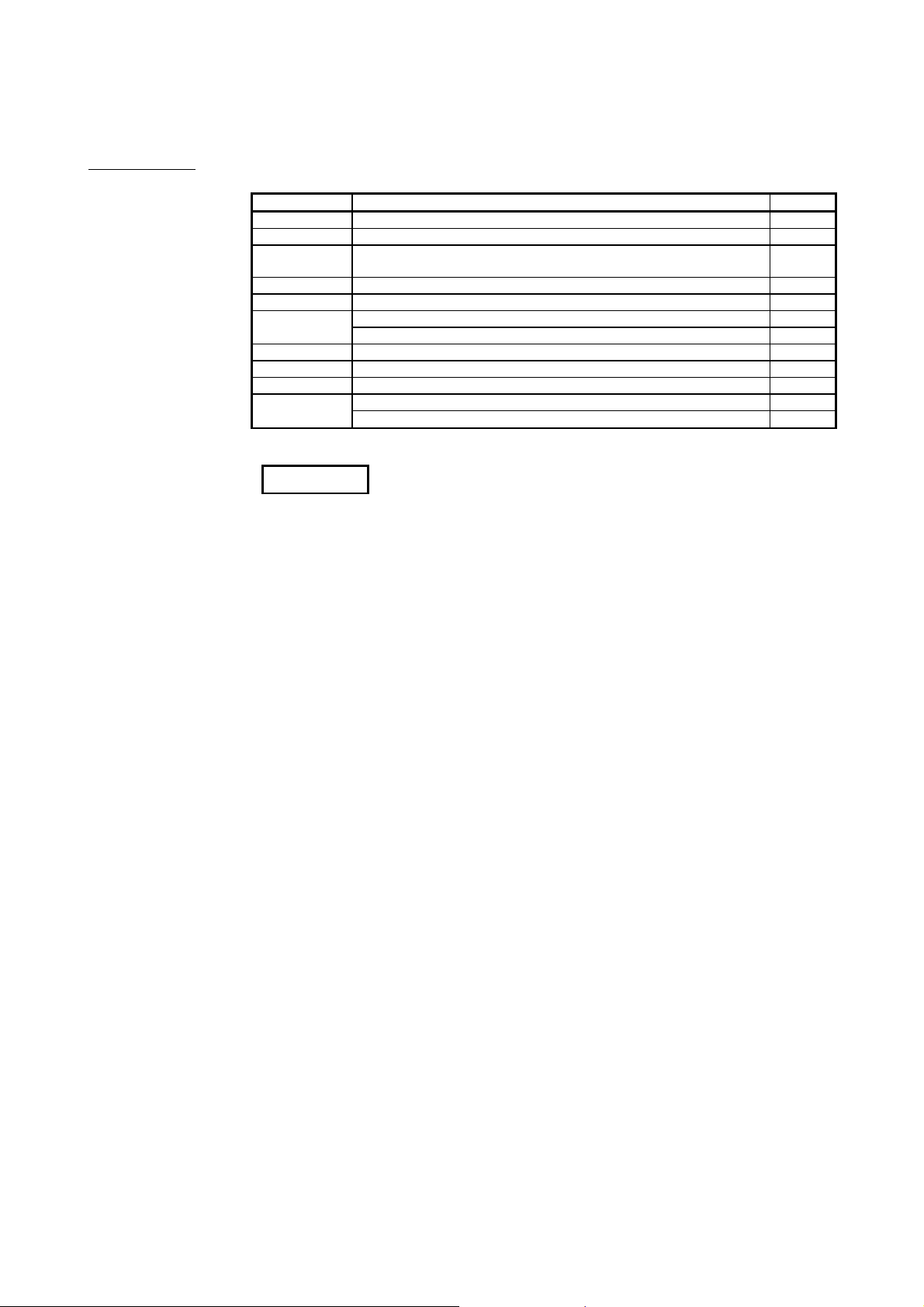
PACKING LIST
Model name Part name Quantity
QJ71LP21 QJ71LP21 MELSECNET/H Network Module (optical loop type) 1
QJ71LP21-25 QJ71LP21-25 MELSECNET/H Network Module (optical loop type) 1
QJ71LP21S-25
QJ71LP21G QJ71LP21G MELSECNET/H Network Module (optical loop type) 1
QJ71LP21GE QJ71LP21GE MELSECNET/H Network Module (optical loop type) 1
QJ71BR11
QJ72LP25-25 QJ72LP25-25 MELSECNET/H Network Module (optical loop type) 1
QJ72LP25G QJ72LP25G MELSECNET/H Network Module (optical loop type) 1
QJ72LP25GE QJ72LP25GE MELSECNET/H Network Module (optical loop type) 1
QJ72BR15
*1: Production of the QJ71LP21 was discontinued in October, 2000.
QJ71LP21S-25 MELSECNET/H Network Module (optical loop type, with
external power supply function)
QJ71BR11 MELSECNET/H Network Module (coaxial bus type) 1
F-type connector (A6RCON-F) 1
QJ72BR15 MELSECNET/H Network Module (coaxial cable bus type) 1
F-type connector (A6RCON-F) 1
REMARKS
For the coaxial bus system, terminating resistors (75 ) are required in the network
terminal stations.
Terminating resistors are not included with the QJ71BR11, QJ72BR15; they must be
purchased separately.
For a list of the model and how to use the terminating resistors, refer to Section
4.8.2.
1
A - 19 A - 19

MEMO
A - 20 A - 20
1 OVERVIEW
MELSEC-Q
1 OVERVIEW
The MELSECNET/H system includes the following 2 types of networks:
1) PLC to PLC network for communications between a control station and normal
stations
2) Remote I/O network for communications between a remote master station and
remote I/O stations
This is the manual to read when building a remote I/O network for MELSECNET/H
systems (hereinafter referred to as MELSECNET/H). For building a MELSECNET/H
PLC to PLC network, please refer to the Q Corresponding MELSECNET/H Network
System Reference Manual. (PLC to PLC network) (SH-080049)
POINT
The Basic model QCPU and safety CPU cannot configure a remote I/O network in
a MELSECNET/H network system.
REMARKS
(1) The previous network, called MELSECNET/10H is now called MELSECNET/H.
(2) A network module installed on the remote master station is referred to as a
master module.
A network module installed on a remote I/O station is referred to as a remote I/O
module.
1
1 - 1 1 - 1
1 OVERVIEW
1.1 Overview
MELSEC-Q
1
The MELSECNET/H remote I/O network system has more functionality and capacity
than the former network system, MELSECNET/10 network system (hereafter referred
to as MELSECNET/10).
As the MELSECNET/H remote I/O network adopts the same module mounting method
as the usual one (mounting I/O modules and intelligent function modules onto the main
and extension base units), each module mounted on the remote I/O stations can be
handled in the similar way as the basic one.
In addition, the usability of the MELSECNET/10 remote I/O network has been further
enhanced so that networks can be easily configured for factory automation systems.
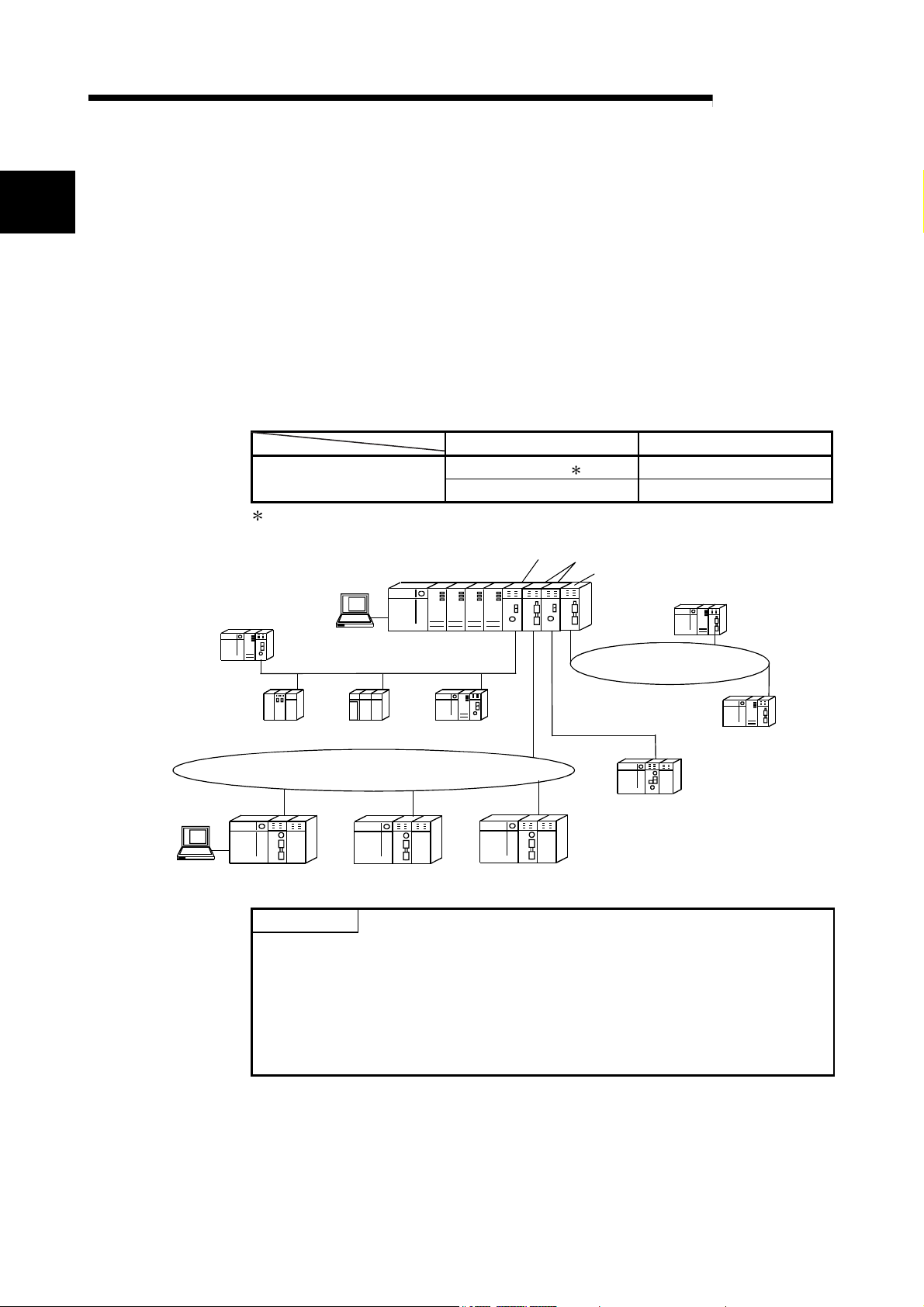
For the optical loop system in the MELSECNET/H remote I/O network, the
communication speed can be set to 25 Mbps or 10 Mbps.
Network system Communication speed
MELSECNET/H
Optical loop
Optical loop, coaxial bus 10 Mbps
1 25 Mbps
1: QJ71LP21-25, QJ71LP21S-25, and QJ72LP25-25 only
Control station (MELSECNET/10 mode)
QCPU normal station
GX Developer
MELSECNET/H (10Mbps)
PLC to PLC network
QCPU
Remote master station
Control station (MELSECNET/H mode)
QCPU normal station
MELSECNET/H (25Mbps)
PLC to PLC network
GX Developer
QnACPU
normal station
MELSECNET/H (25Mbps) remote I/O network
Remote I/O station Remote I/O station Remote I/O station
POINT
(1) Select QCPUs for MELSECNET/H remote I/O networks.
AnUCPU
normal station
QCPU
normal station
(2) Remote I/O networks and PLC to PLC networks cannot be mixed on the same
MELSECNET/H network. Always build separate networks.
(3) Only MELSECNET/H network modules can be connected to a MELSECNET/H
remote I/O network. Any MELSECNET/10 network modules (AJ72LP25,
A1SJ72QLP25, etc.) are not connectable.
MELSECNET/H (10Mbps)
remote I/O network
QCPU normal station
Remote I/O station
1 - 2 1 - 2
1 OVERVIEW
Type of networks
CPU module
QCPU
AnUCPU MELSECNET/10
QnACPU MELSECNET/10
that can be used
MELSECNET/H
(10 Mbps)
MELSECNET/H
(25 Mbps)
The following table shows the types of networks the CPU modules can be connected to.
with CPU
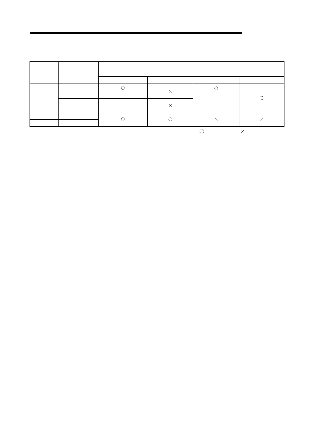
1.2 Features
The MELSECNET/H remote I/O network has the following features.
(1) Realization of a high-speed communication system
(2) Large-scale and flexible system configuration
MELSEC-Q
Network to be connected
MELSECNET/10 MELSECNET/H
PLC to PLC network Remote I/O network PLC to PLC network Remote I/O network
(MELSECNET/10 mode)
(MESLECNET/H mode,
MELSECNET/H
Extended mode)
: Can be used : Cannot be used
(a) High-speed data communication at 10 Mbps/25 Mbps is possible.
(25Mbps is available for only the optical loop type QJ71LP21-25,
QJ71LP21S-25 and QJ72LP25-25.)
(a) The link device has a larger capacity: 16384 points for the link relay (LB),
16384 points for the link register (LW), and 8192 points for the link inputs
(LX)/link outputs (LY). (Refer to Section 2.1.3, "Available device range
settings.")
(b) A maximum of 4096 I/O points can be set for each remote I/O station.
The link points between a remote master station and a remote I/O station
can be set up to 1600 bytes. The link points of up to 2000 bytes can be set
between a master station and a sub-master station on a multiplexed remote
I/O network.
(c) Either of the following systems can be chosen: the optical loop system
which allows a long station-to-station distance and total distance (up to 30
km (98430 ft.)) and is resistant to noise, or the coaxial bus system
(maximum cable distance of 500 m (1640.5 ft.)) which can be wired easily.
(Refer to Section 3.1, "Performance Specifications.")
1 - 3 1 - 3
1 OVERVIEW
MELSEC-Q
(d) The following functions facilitate network connection:
1) Any station to be connected in the future can be specified as a reserved
station.
Specifying a station not actually connected as a reserved station
prevents a communication error. (Refer to Section 5.1.3 "Common
parameter.")
2) It is not necessary to connect stations in order of the station Nos. in the
network. (Refer to Section 4.2.1, 4.2.2.)
(e) The parameters can be written to remote I/O modules using GX Developer
in the same way as to CPU modules.
The parameters of the remote I/O module can be used to change the
detailed settings (response time, error time output mode) for I/O modules
on the remote I/O station, intelligent function module switch settings and I/O
assignments, and remote password settings.
(Refer to Section 5.2 "Remote I/O Station Parameter Settings".)
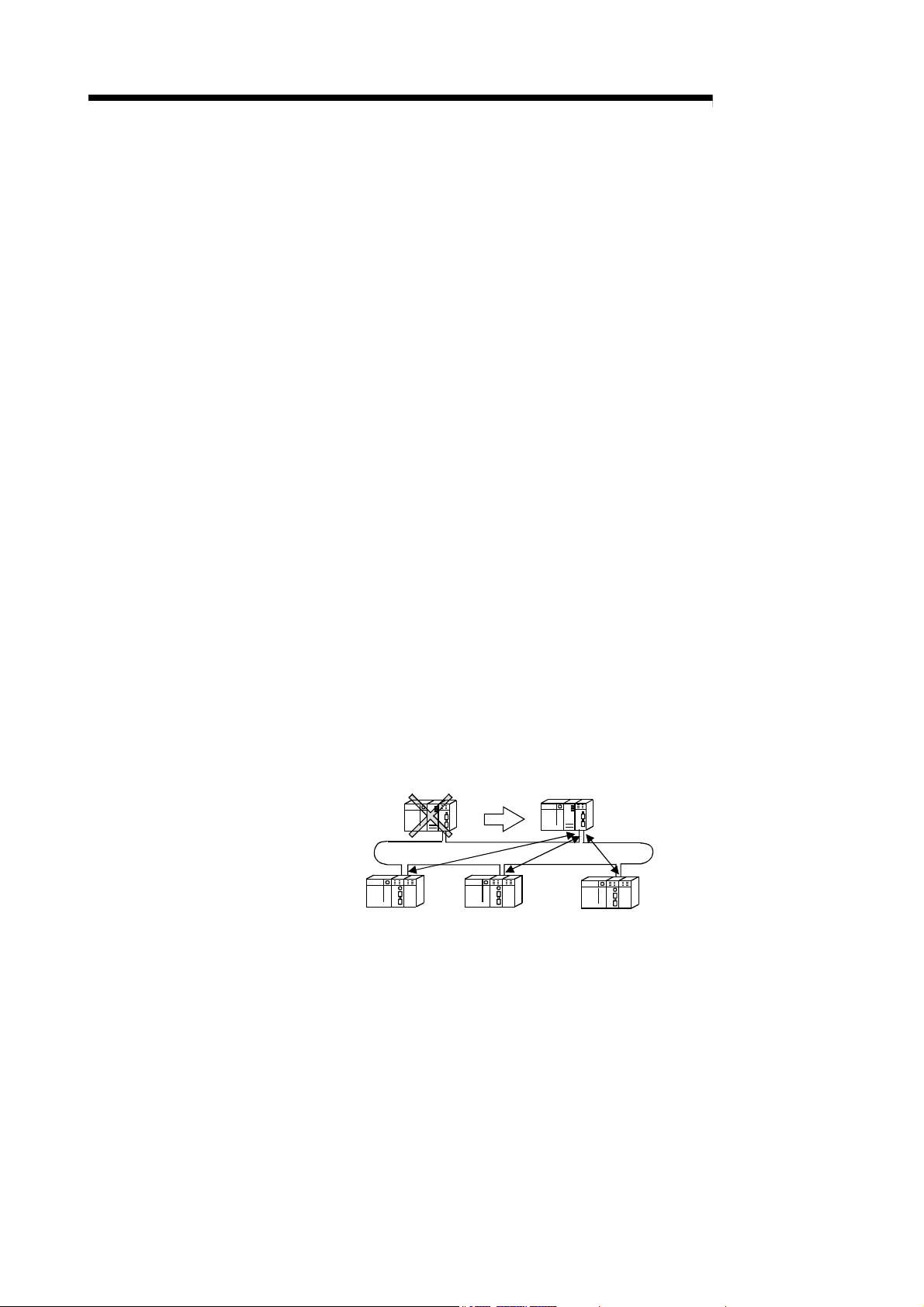
(f) Setting up a master station (DM
) and a sub-master station (DSMR) on the
R
multiplexed remote I/O network allows the sub-master station to take over
the control of remote I/O stations (R) in case of the master station's failure.
(The Process CPU should be used for the multiplexed remote master
station and sub-master station.)
By making a parameter setting, the multiplexed remote sub-master station
can continue the control of the remote I/O stations even if the master
station has recovered to normal and rejoined to the system. (Setting for the
recovered master station to control the remote I/O stations is also
available.)
(Refer to Section 7.10 "Multiplex Remote Master Function (Process CPU)".)
Multiplexed remote
master station (DM
Multiplexed remote
)
sub-master station (DSMR)
R
Remote I/O station (R) Remote I/O station (R) Remote I/O station (R)
1 - 4 1 - 4
1 OVERVIEW
MELSEC-Q
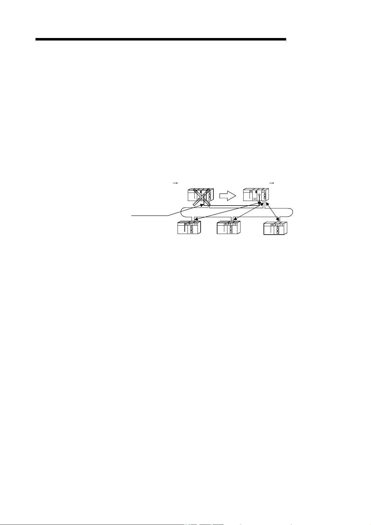
(g) The redundant system uses the multiplex remote master function to control
I/O modules and intelligent function modules. (The Redundant CPU should
be used in the redundant system.)
If the multiplexed master station (control system) fails, the multiplex remote
master function will switch the master station from "control system" to
"standby system". At this time, the multiplexed remote sub-master station is
switched from "standby" to "control", continuing the remote I/O control.
The sub-master station (control system) that is controlling the remote I/O
stations will keep its control even if the master station (standby system) has
returned to normal status.
(Refer to Section 7.11 "Multiplex Remote Master Function for Redundant
System (Redundant CPU)".)
Multiplexed remote master station (DMR)
Control system Standby system
Multiplexed remote sub-master station (DSM
Standby system Control system
)
R
Tracking cable
Remote I/O station (R)
Remote I/O station (R)
Remote I/O station (R)
(h) A maximum of 7 extension base units can be connected to the remote I/O
module (eight base units including the main base unit), allowing the
installation of up to 64 modules.
The maximum overall length of extension cables is 13.2m, ensuring a
flexible layout of extension base units.
1 - 5 1 - 5
1 OVERVIEW
QCPU Master module
Link register W
Refresh
QCPU Master module
Z.REMTO
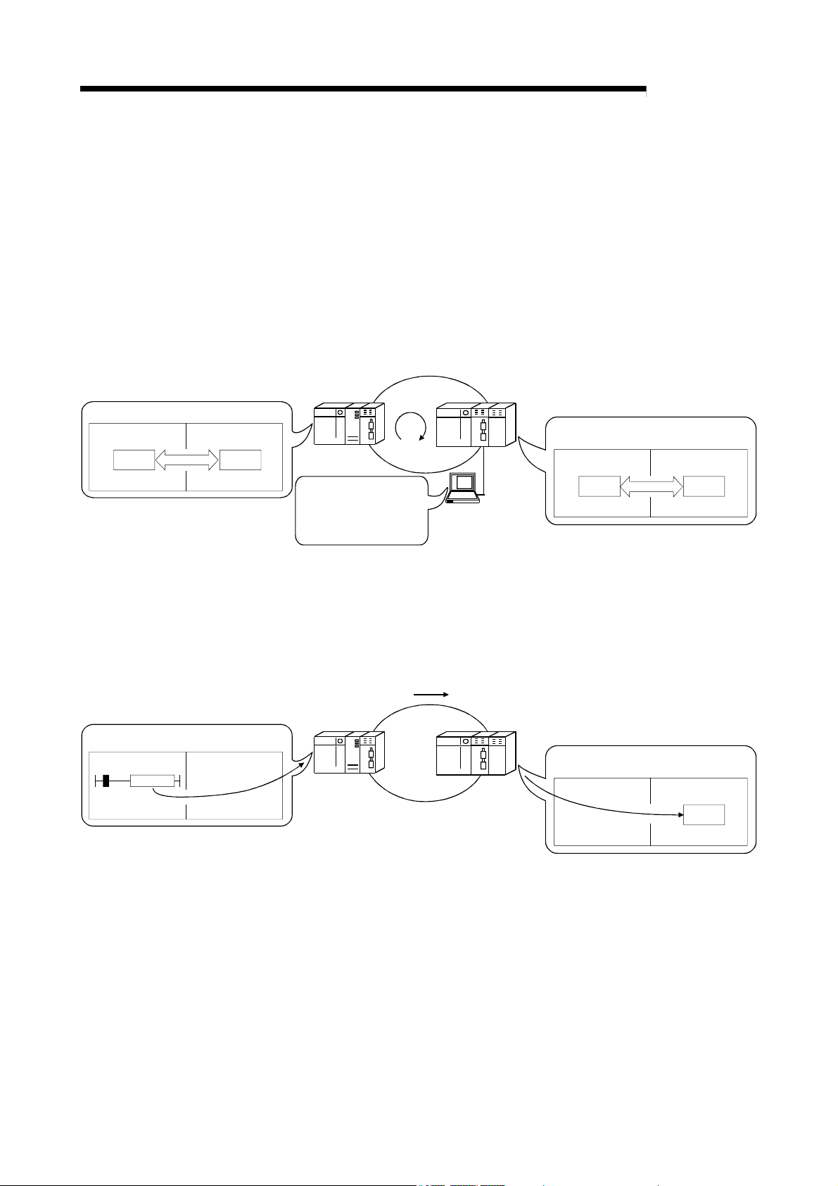
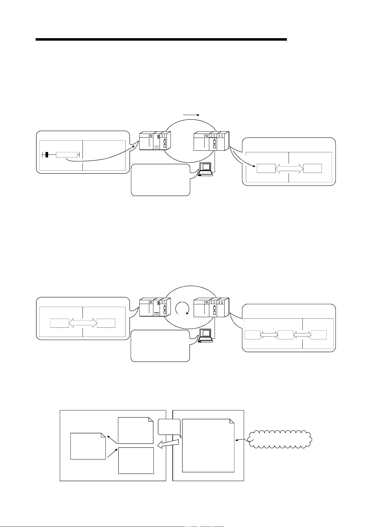
(3) Providing versatile communication services
(a) Reading data from and writing data to intelligent function modules mounted
on remote I/O stations are easy.
There are four methods available for reading and writing.
1) Use GX Configurator to make the initial settings and automatic refresh
settings with intelligent function module parameters, and write them
into the remote I/O module in the remote I/O station.
By refreshing the intelligent function module data to the link register W
of the remote I/O module based on the auto refresh settings, the
remote master station can read/write refreshed data by cyclic
transmission.
Remote I/O station
Intelligent function module
GX
Remote I/O station
Intelligent function module
Link register LW
Remote master station
QCPU
Intelligent function
module parameters
• Initial settings
• Automatic refresh
settings
LW
Configurator
2) Link dedicated instructions can be used to directly read from or write to
the buffer memory of the intelligent module.
• REMFR instruction: Reads data from the buffer memory of the
remote I/O station intelligent function module.
• REMTO instruction: Writes data to the buffer memory of the remote
I/O station intelligent function module.
REMTO
Remote master station
QCPU
Remote I/O module
Link register W
Refresh
Remote I/O module
REMTO
MELSEC-Q
Intelligent
function module
Buffer memory
Intelligent
function module
Buffer memory
1 - 6 1 - 6
1 OVERVIEW
QCPU Master station
JP.WRITE
QCPU Master station
Link register W Link register LW
Refresh
CPU module Network module
I50
Interrupt
sequence
program
IRET
MELSEC-Q
3) By refreshing the intelligent function module data into the remote I/O
module's data register D by the automatic refresh setting of the
intelligent function module parameters, the remote master station can
read/write data from/to the data register D with READ or WRITE
instruction.
WRITE
Remote master station
QCPU
Intelligent function
module parameters
• Initial settings
• Automatic refresh
settings
Configurator
Remote I/O station
Intelligent function module
W
R
GX
Remote I/O module
Data
IT
register D
E
Refresh
Intelligent
function module
memory
4) The automatic refresh setting of the intelligent function parameters
enables the intelligent function module data to be refreshed into the
remote I/O module's data register D. By refreshing the data register D
to the link register W with the parameter of the remote I/O module, the
remote master station can read/write the intelligent function module
data by cyclic transmission.
This method has the advantage that the intelligent function module
parameters created for a QCPU can be applied to the remote I/O
module without making any modifications.
Remote master station
QCPU
Intelligent function
module parameters
• Initial settings
• Automatic refresh
settings
LW
Configurator
Remote I/O station
Intelligent function module
GX
Remote I/O module
Link
register W
Refresh
function module
Data
register D
Refresh
(b) The interrupt sequence program of the host's CPU module can be started
up using the event issue function. This function reduces the response time
of the system and enables real-time data reception.
(Refer to Section 7.7 "Interrupt Settings".)
MELSECNET/H
MAIN
Normal
sequence
program
Conditions
matched
Condition check
Interrupt condition
parameters
• Relay information
• Register data
• Network status
Cyclic transmission
Buffer
Intelligent
Buffer
memory
END
1 - 7 1 - 7

1 OVERVIEW
MELSEC-Q
(4) Enhanced RAS functions (Refer to Section 3.2.2 "RAS functions")
(a) When a faulty station recovers and can resume normal operation, it
automatically returns to the network to resume the data communication
using the automatic return function.
(b) By using the loopback function (in the optical loop system), it is possible to
continue data transmission among operational stations by disconnecting
faulty areas such as a part of the network where there is a cable
disconnection, a faulty station, etc.
(c) By using the station detach function (in the coaxial bus system), even when
some of the connected stations are down due to power off, etc., the normal
communication can be continued among other operational stations.
(d) The network module can continue the transient transmission even if an
error, which stops the CPU module, occurs during system operation.
(e) The time of transient error occurrence can be checked.
(f) By mounting 2 power supply modules on a remote I/O station, either of
them can be replaced without powering off the station. (Redundant power
supply on remote I/O station)
The redundant power supply base unit is required for mounting 2 power
supply modules.
(g) When an input module, an output module or an intelligent function module
mounted on a remote I/O station fails, the faulty module can be replaced
without stopping the system operation. (Online module change)
Online module change is executable for the Q series I/O modules and
modules of function version C and later, such as analog-to-digital converter
modules, digital-to-analog converter modules, channel isolated
thermocouple input modules, and temperature control modules.
REMARKS
The following faults make the RAS functions valid.
• Break in cable
• Power-off of slave station
• Network setting error
• Fault detectable by self-diagnostics of CPU module
If the network module has become faulty, the RAS functions may not be activated
depending on the fault.
(5) Control of external connection to remote I/O stations (refer to
Section 7.12)
Setting a remote password for a remote I/O station restricts access from the
outside via an Ethernet interface module or serial communication module.
(Remote password)
1 - 8 1 - 8

A
1 OVERVIEW
(6) Improved network functions
(a) Intelligent function modules mounted to remote I/O stations can be
diagnosed using the GX Developer system monitor.
Intelligent function modules mounted to remote I/O stations can be
diagnosed using the system monitor of GX Developer, which is connected
to a remote master station or directly connected to a remote I/O station.
MELSEC-Q
Remote I/O station
system monitor
Select
Q64AD
Q64A D
system monitor
GX Developer
Remote I/O station
GX Developer
QCPU
Q64AD
Remote master station
Remote I/O station
GX Developer
When the network seems to be faulty, it can be diagnosed through GX
Developer connected to the remote master station or any remote I/O
station.
(b) If the GX Developer is connected to a remote I/O station, it will not affect the
system operating so user program network function testing can be done online.
It shuts out input (X) from the input module on the remote I/O station and
can turn input (X) on or off using the GX Developer test.
This allows testing of the remote master station input program to be performed.
In addition, it shuts of output (Y) form the remote master station and can
turn remote I/O station output (Y) on and off using the GX Developer test.
This allows testing of the wires for the output module on the remote I/O
station to be performed.
(7) Increased ease of network configuration in combination with GX
Developer
(a) The network parameters can easily be set by visualizing them as pull-down
menus, dialogue boxes, etc.
(b) The settings of network Nos., group numbers and operation modes have
been simplified so that these values can be designated only through
software settings.
(Network parameters)
Pull-down menu
bbreviations
1 - 9 1 - 9

)
1 OVERVIEW
1.3 Abbreviations Used in the Text, Tables and Diagrams of This Manual
MELSEC-Q
(1) Abbreviations
Abbreviation Name
MR Remote master station
R Remote I/O station
DMR Multiplexed remote master
DSMR Multiplexed remote sub-master
(2) Marking format
Station number (1 to 64)
Abbreviation
Network No. (1 to 239
[Example]
1) Network No. 3 and remote master station ································· 3M
R
: Station number "0" is not attached to the remote master station.
2) Network No. 5, remote I/O station, station number 3 ··················· 5R3
3) Network No. 7, Multiplexed remote sub-master, station number 4
·················································································· 7DSM
4
R
1 - 10 1 - 10

1 OVERVIEW
1.4 Functions Added/Changed with Upgrade to Function Version D
The following table lists the additional/altered functions for network modules of function
Function Function version Description Reference
Multiplexed remote I/O
network for redundant
system
Power supply
redundancy on remote
I/O station
Online module change
on remote I/O station
Remote password on
remote I/O station
version D.
Function version D
Function version D
Function version D
Function version D
Allows construction of a multiplexed remote I/O network
that includes the redundant system as the master station.
Allows the construction of the system that includes a
remote I/O station in which 2 power supply modules are
mounted for power supply redundancy.
Allows the faulty I/O module or intelligent function module
on a remote I/O station to be replaced online while the
remote I/O station is running.
Limits the access made from GX Developer via an
Ethernet module or serial communication module
mounted on a remote I/O station, by setting a password.
MELSEC-Q
Section 7.11
Section 3.2.2 (9)
Section 3.2.2
(10)
Section 7.12
1 - 11 1 - 11

r
2 SYSTEM CONFIGURATION
2 SYSTEM CONFIGURATION
MELSEC-Q
This introduces a system comprised of remote I/O networks.
(1) Remote I/O networks and PLC to PLC networks cannot be mixed on the same
2
(2) Only MELSECNET/H network modules can be connected to a MELSECNET/H
2.1 Single Remote I/O Networks
2.1.1 Configuration
(1) Optical loop system
POINT
MELSECNET/H network. Always build separate networks.
remote I/O network. They cannot be mixed with MELSECNET/10 network
modules (AJ72LP25, A1SJ72QLP25, etc.).
Up to 64 remote I/O modules can be connected to a remote master station.
Always set the station number of the remote master station to 0.
Station number 0
(remote master station)
QCPU QJ71
LP21
Power supply
Station number 1
(remote I/O station)
QJ72
I/O
LP25
Power supply
I/O
Station number 2
(remote I/O station)
QJ72
I/O
LP25
Power supply
I/O
Optical fiber cable
QJ72
I/O
LP25
Power supply
Station number 64
(remote I/O station)
I/O
QJ72
I/O
LP25
Power supply
Station number 4
(remote I/O station)
I/O I/O
QJ72
LP25
Power supply
Station number 3
(remote I/O station)
I/O
(2) Coaxial cable bus system
Up to 32 remote I/O stations can be connected to a remote master station.
Always set the station number of the remote master station to 0.
Station number 0
(remote master station)
QCPU
Power supply
Terminating resistor
(Sold separately)
QJ71
BR11
Station number 1
(remote I/O station)
QJ72
I/O
BR15
Power supply
Coaxial cable
I/O
Station number 32
(remote I/O station)
QJ72
I/O
BR15
Power supply
Terminating resisto
(Sold separately)
I/O
2 - 1 2 - 1

2 SYSTEM CONFIGURATION
MELSEC-Q
2.1.2 Setting items
(1) Table 2.1 lists the setting items on the master module of the remote master station
(MR) and the parameter setting items on GX Developer.
Table 2.1 Remote master station setting items
Setting items Remote master station (MR) Reference
Network module switch
STATION NO. 0 Section 4.2.1
MODE
Parameter setting on GX Developer
Setting the number of Ethernet/CC IE/MELSECNET cards
Network type
Starting I/O No.
Network No.
Total stations
Group No. —
Mode
Common parameters
Supplementary setting
Station specific parameters —
Refresh parameters
Valid module during other station access Section 5.1.6
Interlink transmission parameters —
Routing parameters 3
: Always set,
Default setting, : Set as needed, : No need to set
:
MELSECNET/H
(Remote master station)
1: Default values are not set in LX/LY. Set the refresh parameters.
2: Default values are preset for LB/LW.
The CPUs other than the Universal model QCPU may operate even if refresh
parameters have not been set.
For the operation and precautions, refer to Section 5.1.5 (3).
3: Refer to the Q Corresponding MELSECNET/H Network System Reference
Manual (PLC to PLC Network) (SH-080049).
1 2
Section 4.2.2
Section 5.1.1
Section 5.1.2
Section 5.1.2
Section 5.1.2
Section 5.1.2
Section 5.1.3
Section 5.1.4
Section 5.1.5
2
2 - 2 2 - 2

2 SYSTEM CONFIGURATION
(2) Table 2.2 lists the setting items on the remote I/O module of the remote I/O
station (R) and the parameter setting items on GX Developer.
Network module switch
STATION NO. 1 to 64 Section 4.2.2
MODE
Parameter setting on GX Developer
PLC system
PLC RAS
I/O assignment 4
Operation setting Section 5.2.1
Ethernet setting 5
CC-Link setting 6
Remote password setting
GX Configurator setting
Initial setting
Auto refresh setting
4 : Refer to the User's Manual (Function Explanation, Program Fundamentals) for
the CPU module used.
5 : Refer to the Q Corresponding Ethernet Interface Module User's Manual (Basic)
(SH-080009). Note that interrupt setting is not available.
6 : Refer to the MELSEC-Q CC-Link System Master/Local Module User's Manual
(SH-080394E). Note that interrupt setting is not available.
2.1.3 Available device ranges
MELSEC-Q
Table 2.2 Remote I/O station setting items
Setting items Remote I/O station (R) Reference
: Always set,
Default setting, : Set as needed, : No need to set
:
Section 4.2.2
4
4
Section 7.12
Section 5.2.1(4)
Section 5.2.1(4)
The remote I/O network can use the following device ranges within each network
module.
These device ranges indicate the remote master station.
Device Range setting Other
LB 0H to 3FFFH (16384 points)
LW 0H to 3FFFH (16384 points)
LX 0H to 1FFFH (8192 points)
LY 0H to 1FFFH (8192 points)
The device range (excluding that of I/O module mounted on the host
station) should be assigned to each network module.
—
3000
H
Extended 1
: Available device range
3FFF
H2000H
CPU module
Network module
CPU module
Network module
B/W
LB/LW
X/Y
LX/LY
1000
H
0
Actual I/O
1: Expandable by changing from [PLC parameters] - [Device settings]
(4096)
(8192) (12288) (16383)
2 - 3 2 - 3

2 SYSTEM CONFIGURATION
2.2 Multiple Remote I/O Network (Process CPU)
2.2.1 Configuration
A multiplexed remote I/O network system includes a multiplexed remote master station
and a multiplexed remote sub-master station. The multiplexed remote sub-master
station takes control of remote I/O stations when the multiplexed remote master station
fails.
Always assign station No. 0 to the multiplexed remote master station.
It is allowed to assign any of station number 1 to 64 to the multiplexed remote submaster station, provided that the number is not the same as that of remote I/O station.
Sixty-three remote I/O stations can be connected in an optical loop system, 31 stations
in a coaxial bus system.
POINT
Only the Process CPU is the CPU module that works as a multiplexed remote
master station and multiplexed remote sub-master station.
The CPUs other than the Process CPU do not work as a multiplexed remote
master station and multiplexed remote sub-master station.
Station No. 0
(Multiplexed remote
master station)
QnPH
CPU
QJ71
LP21
Station No. 1
(Multiplexed remote
sub-master station)
QnPH
CPU
QJ71
LP21
Station No. 2
(Remote I/O station)
I/OQJ72
LP25
I/O
MELSEC-Q
Power supply
LP25
Power supply
Station No. 64
(Remote I/O station)
I/O
Power supply
Optical fiber cable
LP25
Power supply
Station No. 4
(Remote I/O station)
I/OQJ72
I/O I/OQJ72
Power supply
I/OI/OQJ72
LP25
Power supply
Station No. 3
(Remote I/O station)
Up to 63 remote I/O stations can be connected in an optical loop system.
Up to 31 stations can be connected in a coaxial bus system.
2 - 4 2 - 4

2 SYSTEM CONFIGURATION
2.2.2 Setting items
(1) Table 2.3 lists the parameter setting items of the multiplexed remote master
station (DM
Table 2.3 Setting Items of Multiplexed Remote Master Station and
Multiplexed Remote Sub-Master Station
MELSEC-Q
R) and multiplexed remote sub-master station (DSMR).
Setting item
Network module switch
STATION NO. 0 1 to 64 Section 4.2.1
MODE Section 4.2.1
Parameter setting on GX Developer
Setting the number of Ethernet/CC IE/MELSECNET cards
Network type MELSECNET/H
Starting I/O Section 5.1.2
Network No. Section 5.1.2
Total stations
Group No. Section 5.1.2
Mode Section 5.1.2
Common parameters
Supplementary setting Section 5.1.4
Station specific parameters —
Refresh parameters
Valid module during other
station access
Interlink transmission parameter —
Routing parameters 4
: Always set,
Multiplexed remote
master station (DM
(Multiplexed remote
master station)
2 3
Default setting, : Set as needed, : No need to set
:
Multiplexed remote
sub-master station
R)
(DSM
MELSECNET/H
(Multiplexed remote
sub-master station)
R)
1
1
2 3
Reference
Section 5.1.1
Section 5.1.2
Section 5.1.3
Section 5.1.5
Section 5.1.6
POINT
1: Set Total stations and common parameters of the multiplexed remote sub-
master station when using the multiplexed remote sub-master station to
resume the network. The settings must be the same as those of the
multiplexed remote master station.
For example, if the multiplexed remote master station is powered off and then
on during network control by the multiplexed remote sub-master station, the
multiplexed remote sub-master station resumes networking as a master
operating station.
2 : Default values are not set in LX/LY. Set the refresh parameters.
3 : Default values are preset for LB/LW.
The system may operate even if refresh parameters have not been set.
For the operation and precautions, refer to Section 5.1.5 (3).
4 : Refer to the Q Corresponding MELSECNET/H Network System Reference
Manual (PLC to PLC Network) (SH-080049).
2 - 5 2 - 5

y
2 SYSTEM CONFIGURATION
(2) Table 2.4 lists the setting items that can be set on a remote I/O module operating
as a remote I/O station (R) and the parameter setting items that can be set from
GX Developer.
MELSEC-Q
Table 2.4 Setting Items of a Remote I/O Station
Network module main module switch
STATION NO. 1 to 64 Section 4.2.2
MODE Section 4.2.2
GX Developer parameter setting
PLC system
PLC RAS
I/O assignment
Operation setting
Ethernet setting
CC-Link setting
Remote password setting
GX Configurator setting
Initial setting
Auto refresh setting
5 : Refer to the User's Manual (Function Explanation, Program Fundamentals) for
the CPU module used.
6 : Refer to the Q Corresponding Ethernet Interface Module User's Manual (Basic)
(SH-080009). Note that interrupt setting is not available.
7 : Refer to the MELSEC-Q CC-Link System Master/Local Module User's Manual
(SH-080394E). Note that interrupt setting is not available.
2.2.3 Available device ranges
Setting item Remote I/O station (R)
: Always set,
Default setting, : Set as needed, : No need to set
:
Reference
5
5
5
Section 5.1.2
6
7
Section 7.12
Section 5.2.1(4)
Section 5.2.1(4)
The remote I/O network can use the following ranges of devices inside network
modules.
Device Available Range Others
LB 0H to 3FFFH (16384 points)
LW 0H to 3FFFH (16384 points)
LX 0H to 1FFFH (8192 points) The device range (excluding that of I/O module
LY 0H to 1FFFH (8192 points)
mounted on the host station) should be assigned to
each network module.
—
1000
H
0
CPU module
Network module
CPU module
Network module
B/W
LB/LW
X/Y
LX/LY
Actual I/O
1: Expandable b
(4096)
changing from [PLC parameters] - [Device settings]
(8192) (12288) (16383)
3000H
Extended 1
: Available device range
2 - 6 2 - 6
3FFF
H2000H

2 SYSTEM CONFIGURATION
2.3 Multiplexed Remote I/O Network for Redundant System (Redundant CPU)
2.3.1 Configuration
The redundant system including the Redundant CPU utilizes the multiplexed remote
I/O network system in order to control I/O modules and intelligent function modules.
In the multiplexed remote I/O network system for the redundant system, the master
module on the side of the control Redundant CPU (started up as a control system) acts
as a multiplexed remote master station and controls remote I/O stations, while the
master module mounted on the side of the standby Redundant CPU performs the submaster operation as a multiplexed remote sub-master station.
When the control system CPU or the multiplexed remote master station goes down,
the multiplexed remote sub-master station switches from "standby" to "control" and
takes over the control of the remote I/O stations.
Make sure to assign No.0 to the master module mounted on the system A CPU in the
redundant system.
For the station No. of the multiplexed remote sub-master station, set any of No. 1 to
64, which should not be the same as the station No. of the remote I/O stations.
The number of remote I/O stations connectable to a multiplexed remote I/O network for
the redundant system is 63 in the optical loop system and 31 in the coaxial bus
system.
POINT
The CPU module applicable for the multiplexed remote master or sub-master
station in the redundant system is the Redundant CPU only.
The CPUs other than the Redundant CPU are not applicable.
MELSEC-Q
REMARKS
Refer to the QnPRHCPU User's Manual (Redundant System) for details on the
redundant system.
Station No. 0
(Multiplexed remote master station)
System
QnPRH
CPU
Power supply
QJ71
A
LP21
QJ72
LP25
Power supply
Station No. 64
(Remote I/O station)
Station No. 1
(Multiplexed remote sub-master station)
System
QJ71
B
LP21
QJ72
LP25
Power supply
Power supply
Tracking cable
I/O
I/O
QnPRH
CPU
Optical fiber cable
Station No. 4
(Remote I/O station)
I/O
I/O
Station No. 2
(Remote I/O station)
QJ72
I/O
I/O
I/O
I/O
LP25
Power supply
QJ72
LP25
Power supply
Station No. 3
(Remote I/O station)
In the optical loop system, up to 63 remote I/O stations can be connected.
Connection of up to 31 stations is allowed for the coaxial bus system.
2 - 7 2 - 7

2 SYSTEM CONFIGURATION
2.3.2 Setting items
(1) Table 2.5 lists the parameter setting items of the multiplexed remote master
station (DM
In the redundant system, the same network parameters are set to both the
control and standby systems. For this reason, parameter setting for the
multiplexed remote sub-master station is not required.
Make sure to assign No.0 to the master module mounted on the system A CPU
in the redundant system.
Table 2.5 Setting Items of a Multiplexed Remote Master Station and
R) and multiplexed remote sub-master station (DSMR).
a Multiplexed Remote Sub-master Station
MELSEC-Q
R)
Remote sub-
master station
R)
(DSM
Reference
Section 4.2.1
Section 5.1.1
Section 5.1.2
Section 5.1.2
Section 5.1.2
—
Section 5.1.2
Section 5.1.3
Section 5.1.4
—
Section 5.1.5
Section 5.1.6
—
Section 5.1.7
3
Setting items
Tracking cable connector System A System B Section 7.1.1
Network module switch
STATION NO. 0 1 to 64 Section 4.2.1
MODE
Parameter setting on GX Developer
Setting the number of Ethernet/CC IE/MELSECNET cards
Network type
Starting I/O No.
Network No.
Total stations
Group No.
Mode
Common parameters
Supplementary setting
Station specific parameters
Refresh parameters
Valid module during other station access
Interlink data transfer parameters
Setting of redundant configuration
Routing parameters
: Always set,
Default setting, : Set as needed, : No need to set
:
Remote master
station (M
MELSECNET/H
(Remote master
station)
1 2
1: Default values are not set in LX/LY. Set the refresh parameters.
2: Default values are preset for LB/LW.
The system may operate even if refresh parameters have not been set.
For the operation and precautions, refer to Section 5.1.5 (3).
3: Refer to the Q Corresponding MELSECNET/H Network System Reference
Manual (PLC to PLC Network) (SH-080049).
2 - 8 2 - 8

2 SYSTEM CONFIGURATION
(2) Table 2.6 lists the setting items on the remote I/O module, parameter setting
items on GX Developer and intelligent function module parameter setting items
on GX Configurator.
MELSEC-Q
Table 2.6 Setting Items of a Remote I/O Station
Network module main module switch
STATION NO. 1 to 64 Section 4.2.2
MODE Section 4.2.2
GX Developer parameter setting
PLC system
PLC RAS
I/O assignment
Operation setting
Ethernet setting
CC-Link setting
Remote password setting
GX Configurator setting
Initial setting
Auto refresh setting
4 : Refer to the User's Manual (Function Explanation, Program Fundamentals) for
the CPU module used.
5 : Refer to the Q Corresponding Ethernet Interface Module User's Manual (Basic)
(SH-080009). Note that interrupt setting is not available.
6 : Refer to the MELSEC-Q CC-Link System Master/Local Module User's Manual
(SH-080394E). Note that interrupt setting is not available.
2.3.3 Available device ranges
Setting item Remote I/O station (R)
: Always set,
Default setting, : Set as needed, : No need to set
:
Reference
4
4
4
Section 5.2.1
5
6
Section 7.12
Section 5.2.1(4)
Section 5.2.1(4)
The remote I/O network can use the following device ranges in the network module.
Device Available range Others
LB 0H to 3FFFH (16384 points)
LW 0H to 3FFFH (16384 points)
LX 0H to 1FFFH (8192 points)
LY 0H to 1FFFH (8192 points)
The device range (excluding that of I/O module mounted on the host
station) should be assigned to each network module.
—
3000H
Extended 1
: Available device range
3FFF
H
CPU module
Network module
CPU module
Network module
B/W
LB/LW
X/Y
LX/LY
1000
H
0
Actual I/O
1: Expandable by changing from [PLC parameters] - [Device settings]
(4096)
2000
H
(8192) (12288) (16383)
2 - 9 2 - 9

2 SYSTEM CONFIGURATION
2.4 Multiple Remote I/O Network
2.4.1 Configuration
A multiple remote I/O network system is a network system with many networks
connected to it.
Set a unique number. The numbers can be set within a range from 1 to 239.
Up to four master modules can be mounted on the remote master station.
Note that, however, there are restrictions on the number of master modules that can
be mounted, depending on the CPU module used. (Refer to Section 2.5.)
QCPU QJ71
Power supply
1M
LP21
MELSEC-Q
R
2M
QJ71
LP21
R
Power supply
QJ72
LP25
1R1
Remote I/O net
I/O
I/O
Power supply
QJ72
LP25
1R2
I/O
I/O
Power supply
QJ72
LP25
2R1
Remote I/O net
I/O
I/O
Power supply
QJ72
LP25
2R2
I/O
I/O
2 - 10 2 - 10

2 SYSTEM CONFIGURATION
2.4.2 Setting items
(1) Table 2.7 lists the setting items for the master module main module for a remote
master station (MR) and the parameter settings from the GX Developer.
Network module main module switch
STATION NO. 0 Section 4.2.1
MODE
Parameter setting on GX Developer
Setting the number of Ethernet/CC IE/MELSECNET cards
Network type
Starting I/O No.
Network No.
Total number of remote modules
Group No. —
Mode
Common parameters
Supplementary setting
Station specific parameters —
Refresh parameters
Valid module during other station access
Inter-link data transfer parameters —
Routing parameters
1: Default values are not set in LX/LY. Set the refresh parameters.
2: Default values are preset for LB/LW.
The CPUs other than the Universal model QCPU may operate even if refresh
parameters have not been set.
For the operation and precautions, refer to Section 5.1.5 (3).
3: Refer to the Q Corresponding MELSECNET/H Network System Reference
Manual (PLC to PLC Network) (SH-080049).
MELSEC-Q
Table 2.7 Remote master station setting items
Setting items Remote master station (MR) Reference
: Always set,
MELSECNET/H
(Remote master station)
1 2
Default setting, : Set as needed, : No need to set
:
Section 4.2.1
Section 5.1.1
Section 5.1.2
Section 5.1.2
Section 5.1.2
Section 5.1.2
Section 5.1.3
Section 5.1.4
Section 5.1.5
Section 5.1.6
3
2 - 11 2 - 11

2 SYSTEM CONFIGURATION
(2) Table 2.8 lists the setting items for the remote I/O module main module for the
remote I/O station (R) and the parameter setting items from the GX Developer.
Network module main module switch
STATION NO. 1 to 64 Section 4.2.2
MODE
GX Developer parameter setting
PLC system
PLC RAS
I/O assignment 4
Operation setting Section 5.2.1
Ethernet setting 5
CC-Link setting 6
Remote password setting
GX Configurator setting
Initial setting
Auto refresh setting
4 : Refer to the User's Manual (Function Explanation, Program Fundamentals) for
the CPU module used.
5 : Refer to the Q Corresponding Ethernet Interface Module User's Manual (Basic)
(SH-080009). Note that the interrupt setting is not available.
6 : Refer to the MELSEC-Q CC-Link System Master/Local Module User's Manual
(SH-080394E). Note that the interrupt setting is not available.
2.4.3 Available device ranges
MELSEC-Q
Table 2.8 Remote I/O station setting items
Setting items Remote I/O station (R) Reference
: Always set,
Default setting, : Set as needed, : No need to set
:
Section 4.2.2
4
4
Section 7.12
Section 5.2.1(4)
Section 5.2.1(4)
The remote I/O network can use the following device ranges in the network module.
Device Available range Others
LB 0H to 3FFFH (16384 points)
LW 0H to 3FFFH (16384 points)
LX 0H to 1FFFH (8192 points)
LY 0H to 1FFFH (8192 points)
The device range (excluding that of I/O module mounted on the host
station) should be assigned to each network module.
—
1000
H
0
CPU module
Remote I/O network 1
CPU module
Remote I/O network 1
B/W
LB/LW
LB/LWRemote I/O network 2
X/Y
LX/LY
LX/LYRemote I/O network 2
Real I/O
1: Expandable by changing from [PLC parameters] - [Device settings]
(4096)
2000
H
(8192) (12288) (16383)
Extended function area 1
3000H
3FFF
2 - 12 2 - 12
H

2 SYSTEM CONFIGURATION
2.5 Applicable Systems
2.5.1 Applicable systems for remote master stations
This section describes applicable systems of remote master stations.
No. of mountable modules is the maximum number of mountable network modules
with CC-Link IE Controller Network.
(1) Applicable modules and base units, and No. of modules
(a) Mounting with a CPU module
For the CPU modules and base units applicable to the master module and
the number of mountable master modules, refer to the following.
• User’s manual for the CPU module used.
Depending on the combination with other modules or the number of
mounted modules, power supply capacity may be insufficient.
Pay attention to the power supply capacity before mounting modules, and if
the power supply capacity is insufficient, change the combination of the
modules.
(b) Mounting to a MELSECNET/H remote I/O station
The master module cannot be mounted to any MELSECNET/H remote I/O
station.
Mount it to a CPU module on a master station.
(2) Support of the multiple CPU system
When using the network module in a multiple CPU system, refer to the QCPU
User’s Manual (Multiple CPU System) first.
To construct the remote I/O network with a multiple CPU system, use a master
module of function version B or later.
For precautions for the use in a multiple CPU system, refer to Section 2.6.
MELSEC-Q
2 - 13 2 - 13

2 SYSTEM CONFIGURATION
MELSEC-Q
(3) Network type
The available network type varies depending on the CPU module type, the
function version of the master module, and the version of GX Developer/GX
Network type CPU module Master module GX Developer GX Works2
Multiplexed remote
I/O network for
redundant system
Multiple remote I/O
network
Remote I/O
network
Q12PRHCPU, Q25PRHCPU
Q02PHCPU, Q06PHCPU
Q12PHCPU, Q25PHCPU
Q02CPU, Q02HCPU, Q06HCPU,
Q12HCPU, Q25HCPU,
Q12PHCPU, Q25PHCPU
Q00UJCPU, Q00UCPU,
Q01UCPU
Q02UCPU, Q03UDCPU,
Q04UDHCPU, Q06UDHCPU
Q10UDHCPU, Q20UDHCPU
Q13UDHCPU, Q26UDHCPU
Q03UDECPU, 04UDEHCPU,
Q06UDEHCPU,Q13UDEHCPU,
Q26UDEHCPU
Q10UDEHCPU, Q20UDEHCPU
Q50UDEHCPU, Q100UDEHCPU
Q03UDVCPU, Q04UDVCPU,
Q06UDVCPU, Q13UDVCPU,
Q26UDVCPU
Works2.
Function version D or
later
Function version B or
later
(Serial No. (first five
digits) "04012" or later)
Function version B or
later
(Serial No. (first five
digits) "04012" or later)
Function version B or
later
Function version B or
later
Function version B or
later
Function version B or
later
Function version B or
later
Function version B or
later
Function version B or
later
Function version B or
later
Function version B or
later
Version 8.18U or later
Version 8.68W or later
Version 7.10L or later
Version 6 or later
Version 8.76E or later
Version 8.48A or later
Version 8.76E or later
Version 8.62Q or later
Version 8.68W or later
Version 8.76E or later
Not supported
Not supported
Version 1.87R or
later
Version 1.40S or
later
Version 1.95Z or
later
2 - 14 2 - 14

2 SYSTEM CONFIGURATION
2.5.2 Applicable systems for remote I/O stations
This section explains application systems of remote I/O stations.
Mount a remote I/O module to a CPU slot of any of the main base units.
(1) Applicable main base units, power supply modules and No. of
modules
Main base unit*1 Power supply module
Q33B, Q35B, Q38B, Q312B Q6 P
Q35BL, Q38BL
(Q series large type main base
unit)
Q35BLS, Q35BLS-D, Q38BLS,
Q38BLS-D
(AnS size Q series large type main
base unit)
Q32SB, Q33SB, Q35SB
(Slim type main base unit)
Q6
P
Q6
P
Q61SP
MELSEC-Q
Number of mountable
remote I/O modules
1 (mounted in the CPU
slot)
*2
Q35DB, Q38DB, Q312DB
(Multiple CPU high-speed main
base unit)
Q38RB
(Main base unit for the redundant
power supply system)
Q6
P
Q63RP, Q64RP
*1: Total of up to 64 modules can be mounted to a base unit. Mount a module
within the number of I/O points for the remote I/O module. If the number of
slots is within the available range, the module can be mounted on any slot.
*2: Depending on the combination with other modules or the number of
mounted modules, power supply capacity may be insufficient.
Pay attention to the power supply capacity before mounting modules, and if
the power supply capacity is insufficient, change the combination of the
modules.
2 - 15 2 - 15

2 SYSTEM CONFIGURATION
(2) Applicable extension base units
A system with a remote I/O module can be connected with extension base units.
Q63B, Q65B, Q68B, Q612B
(Extension base unit (type requiring power supply
module))
Q53B, Q55B
(Extension base unit (type requiring no power supply
module))
Q65BL, Q68BL
(Q series large type extension base unit (type
requiring power supply module))
Q55BL
(Q series large type extension base unit (type
requiring no power supply module))
Q65BLS, Q65BLS-D, Q68BLS, Q68BLS-D
(AnS size Q series large type extension base unit
(type requiring power supply module))
Q55BLS, Q55BLS-D
(AnS size Q series large type extension base unit
(type requiring no power supply module))
Q68RB
(Extension base unit for redundant power supply
system)
*1
*1: When using an extension base unit (type requiring no power supply
module), calculate the operating voltage of the unit to check that it is within
the specified range.
1) For the calculation method, refer to the QCPU User's Manual (Hardware
2) For the current consumption of modules mounted on the base unit, refer
*2: Note the following points when using extension cables.
1) Do not install extension cables together with the main circuit (high
2) Connect an extension cable from the OUT of the extension cable
(3) Network type
The available network type varies depending on the function version of the
remote module and the version of GX Developer.
Network type Remote I/O module GX Developer GX Works2
Multiplexed remote
I/O network for
redundant system
Multiple remote I/O
network
Remote I/O network
MELSEC-Q
Extension base unit
Extension cable
(Maximum distance:
13.2m or less)
QC05B, QC06B,
*1
*1
QC12B, QC30B,
QC50B, QC100B
model
*2
Number of
extension base
units
Up to 7
Design, Maintenance and Inspection).
to the manual of the corresponding module.
voltage, large current) cables.
connector of the base unit to the IN of the next extension base unit.
Function version D or later
Version 6 or later
Function version B or later Version 1.40S or later
Version 1.87R or later
2 - 16 2 - 16

2 SYSTEM CONFIGURATION
(4) Applicable modules
The Q series modules can be used on remote I/O stations.
Note that some modules have restrictions.
(a) Functional restrictions
The use of interrupt pointers and dedicated instructions for intelligent
function modules are not supported.
For the restrictions of functions for each module, refer to the user's manual
for the module used.
(b) No. of mountable modules
QJ71E71-B5, QJ71E71-B2,
QJ71E71-100, QJ71E71
QJ61BT11N, QJ61BT11 Up to 4
Modules other than those listed above Up to 64
1: The module with function version B or later is available.
(5) Units/modules not applicable
The following units/modules cannot be used on remote I/O stations.
Redundant type extension base unit Q65WRB
AnS series extension base unit QA1S65B, QA1S68B, QA65B, QA68B
CC-Link IE Controller Network module QJ71GP21-SX, QJ71GP21S-SX
CC-Link IE Field Network master/local
module
MELSECNET/H module
Web server module QJ71WS96
MES interface module QJ71MES96
AS-i master module QJ71AS92
High speed data logger module QD81DL96
High speed data communication
module
Interrupt module
1: These modules cannot be used when switched to interrupt modules by
turning off the function selecting switch (SW2).
(6) ERR. contact of the power supply module
The operation of the ERR. contact of the power supply module differs depending
on the combination with the base unit used. For the operation of the ERR.
contact, refer to the QCPU User's Manual (Hardware Design, Maintenance and
Inspection).
MELSEC-Q
Module Name No. of mountable modules
Up to 41
Item Module model name
QJ71GF11-T2
QJ71LP21, QJ71LP21-25, QJ71LP21S-25,
QJ71LP21G, QJ71BR11, QJ71NT11B
QJ71DC96
QI60, QX40H
1, QX70H 1, QX80H 1, QX90H1
2 - 17 2 - 17

2 SYSTEM CONFIGURATION
(7) Online module change
In the following cases, the online module change cannot be performed.
(a) When an extension base unit (type requiring no power supply module)
(Q52B, Q55B, Q55BL, Q55BLS, or Q55BLS-D) is used (No module
mounted on any extension base unit can be changed online.)
(b) When a slim type power supply module (Q61SP) is used
(8) MELSECNET/10 mode
The MELSECNET/10 mode can be set with the remote I/O module whose serial
No. (first five digits) is "15012" or later.
(9) Precautions for mounting an intelligent function module
Note that the number of intelligent function module parameters that may be set
(initial setting, automatic refresh setting) is limited on the remote I/O module.
If the number of parameters set exceeds the limited number, the remote I/O
module detects the "SP. PARA ERROR (3301)" error.
To auto refresh the excessive parameters, use the REMFR/REMTO instruction to
read/write data from/to the intelligent function module.
Initial setting Up to 512
Auto refresh setting Up to 256
The number of parameters for initial setting is fixed for each intelligent function
module. To check the numbers of parameters for initial setting, refer to the user's
manuals for the corresponding intelligent function modules.
For the way to count the number of parameters for automatic refresh setting,
refer to Section 5.2.1 (4).
MELSEC-Q
Item No. of the parameters that can be set
2 - 18 2 - 18

2 SYSTEM CONFIGURATION
MELSEC-Q
2.6 When Using a Multiple CPU System
Take the following points into consideration when configuring a remote I/O network by
utilizing multiple CPU system.
(1) Use the master module of function version B or later.
(2) Set the network parameters to the control CPU controlling the master module.
(3) It is possible to set up to four master modules per control CPU. Note that the
(a) CPU No. 1 controls all master modules (b) CPU No. 1 and CPU No. 2 control each master
maximum number of mountable master modules per multiple CPU system is four.
module
QJ71
QJ71
QJ71
BR11
QJ71
BR11
CPU
No. 1
CPU
No. 2
QJ71
BR11
QJ71
BR11
QJ71
BR11
QJ71
BR11
CPU
No. 1
CPU
No. 2
BR11
BR11
(c) CPU No 1 to No. 4 control each master module (d) The maximum number of mountable master
CPU
No. 1
CPU
No. 2
CPU
No. 3
CPU
No. 4
QJ71
BR11
QJ71
BR11
QJ71
BR11
QJ71
BR11
modules per system is four
QJ71
CPU
No. 2
QJ71
BR11
BR11
CPU
No. 1
QJ71
BR11
QJ71
BR11
QJ71
BR11
: The number of mounted modules exceeds the limit by one.
2 - 19 2 - 19

2 SYSTEM CONFIGURATION
(4) By connecting to a remote I/O station for access to other stations, GX Developer
can access stations in the other network system, whether the relay stations in the
multiple CPU system are controlled by the same or different CPUs.
Also, GX Developer can access either the control CPU or non-control CPU in the
multiple CPU system.
(a) Accessible to the remote I/O stations in another
network
GX Developer
MELSEC-Q
(b) Accessible to the control CPU in another network
GX Developer
CPU
CPU
No. 1
No. 2
CPU No.1 is
control CPU
QJ72
BR15
QJ71
BR11
QJ71
BR11
I/O
QJ72
BR15
I/O
I/O
I/O
(c) Accessible to the non-control CPUs in another
network
GX Developer
CPU
No. 1
CPU
No. 2
CPU
No. 1
QJ72
BR15
QJ71
BR11
CPU
No. 2
QJ71
BR11
I/O
QJ71
BR11
I/O
CPU No.1 is
control CPU
CPU No.1 is
control CPU
(d) Accessible to another network even if the relayed
station is controlled by another control CPU
GX Developer
CPU
No. 2
CPU
No. 1
QJ72
BR15
QJ71
BR11
CPU
No. 2
I/O
QJ71
BR11
QJ71
BR11
I/O
CPU No.2 is
control CPU
CPU No.1 is
control CPU
QJ72
BR15
QJ71
CPU
No. 1
CPU
No. 2
CPU
No. 1
BR11
CPU
No. 2
QJ71
BR11
QJ71
BR11
I/O
I/O
CPU No.1 is
control CPU
CPU
No. 1
CPU No.1 is
control CPU
CPU No.1 is
control CPU
2 - 20 2 - 20

2 SYSTEM CONFIGURATION
(5) When all of the following conditions from a) to d) are met, use a MELSECNET/H
module whose serial No. (first five digits) is "10042" or later.
(a) A multiple CPU system containing a Built-in Ethernet port QCPU is
configured.
(b) To the Ethernet port of the Built-in Ethernet port QCPU, GX Developer or
GOT is connected.
(c) From GX Developer or GOT, access is made to another station through a
MELSECNET/H module controlled by another CPU.
(d) The access target on another station is an A/QnA series CPU module.
MELSEC-Q
2 - 21 2 - 21

2 SYSTEM CONFIGURATION
2.7 Checking Function Version and Serial No.
The serial No. and function version of the network module can be confirmed on the
rating plate and GX Developer's system monitor.
(1) Checking the serial No. on the rating plate
The rating plate is situated on the side face of the network module.
MELSEC-Q
Serial No.
(first five digits)
Function version
Relevant regulation
standards
(2) Checking on the front of the module
The serial No. and function version on the rating plate are also indicated on the
front of the module (lower part).
The following network module is not included.
• QJ71LP21
2 - 22 2 - 22

2 SYSTEM CONFIGURATION
(3) Checking the serial No. on the system monitor (Product Information
List)
To display the system monitor, select [Diagnostics] [System monitor]
Product Inf. List button of GX Developer.
MELSEC-Q
(a) Production number display
Since the network module does not support the production number display,
"-" is displayed.
POINT
The serial No. displayed in the Product Information List of GX Developer may be
different from the one on the rating plate and the front of the module.
• The serial No. on the rating plate and the front of the module indicates the
management information of the product.
• The serial No. in the Product Information List of GX Developer indicates the
functional information on the product, which is updated when a new function is
added.
2 - 23 2 - 23

3 SPECIFICATIONS
MELSEC-Q
3 SPECIFICATIONS
The following describes the network system specifications, performance specifications
and the specifications for sending and receiving link data.
For general specifications, refer to the user's manual of the CPU module to be used on
the network system.
3.1 Performance Specifications
3.1.1 Optical loop system performance specifications
Item
Maximum
number of links
per network
Maximum number of links per
station
Maximum I/O points per remote
I/O station
Device points per
remote I/O station
Communication speed 10 Mbps
Number of stations per network 65 stations (Remote master stations: 1 Remote I/O stations: 64)2
Overall distance 30 km
Distance
between
stations
Network cable Optical fiber cable (procured by a user)3
Applicable connectors 2-core optical connector plug (procured by a user)
Maximum number of networks 239 (Total including PLC to PLC networks)
Transmission path format Duplex loop
Communication method Token ring
Synchronization method Frame synchronization
Coding method NRZI code (Non Return to Zero Inverted)
Transmission format HDCL standards (Frame format)
Error control CRC (X16 + X12 + X5 + 1) and retry by timeover
RAS functions
Application function • Remote password for remote I/O station
Transient transmission
3
LX/LY 8192 points
LB
LW
25 Mbps —
10 Mbps
Table 3.1 lists the performance of the optical loop system.
Table 3.1 Optical loop system performance specifications
QJ71LP21 QJ71LP21G QJ71LP21GE QJ71LP21-25 QJ71LP21S-25 QJ72LP25-25 QJ72LP25G QJ72LP25GE
16384 points (Remote master station
16384 points (Remote master station
• Remote Master Station
• Remote I/O station Remote Master Station ((LX + LB)/8 + (2 LW)) 1600 bytes
• Multiplexed remote master station multiplexed remote sub-master station ((LY + LB) /8 + (2 LW)) 2000 bytes
M 8192 points
SM 2048 points
D 12288 points
SD 2048 points
SI optical
cable :
500m
H-PCF
optical cable :
1km
band H-PCF
optical cable :
1km
optical cable :
1km
• Loop-back function due to error detection or broken cable
• Diagnostic function for checking local link lines
• Detection using link special relays or link special registers
• Backup of power suppl y on a remote I/O station
• Online module change in a remote I/O station
• 1:1 communication (Monitor, program upload/download, etc.)
• Various send/receive commands from the programmable controller program (READ/WRITE,REMFR/REMTO)
Broad-
QSI
GI-50/125
optical cable
: 2km
Remote master station Remote I/O station
station, remote I/O station
station, remote I/O station
Remote I/O station ((LY + LB)/8 + (2 LW)) 1600 bytes1
If the X/Y numbers are the same, only one side is taken into consideration.
GI-62.5/125
optical cable :
2km
remote sub-master station, remote I/O station: 8192 points, remote sub-master
remote sub-master station, remote I/O station: 8192 points, remote sub-master
SI optical cable : 200m
H-PCF optical cable : 400m
Broad-band H-PCF
optical cable : 1km
SI optical cable: 500m
1km
1km
remote master station: 8192 points)
remote master station: 8192 points)
X + Y 4096 points
25 Mbps /10 Mbps /
(selected with MODE switch)
QSI optical cable : 1km
H-PCF optical cable:
Broad-band H-PCF optical cable:
QSI optical cable: 1km
GI-50/125
optical cable :
2km
10 Mbps
—
GI-62.5/125
optical cable :
2km
3
3 - 1 3 - 1

2
y
3 SPECIFICATIONS
Item
QJ71LP21 QJ71LP21G QJ71LP21GE QJ71LP21-25 QJ71LP21S-25 QJ72LP25-25 QJ72LP25G QJ72LP25GE
Number of occupied I/O points 32 points (Intelligent function module: 32 points)
Voltage
External
Power
3
Supply
5 V DC internal current
consumption
External dimensions
Weight 0.11 kg 0.20 kg 0.15 kg
Current
Size of terminal
screw
Suitable crimp
terminal
Suitable cable size
Tightening torque
Allowable
momentary power
failure time
Noise immunity —
98 (3.86)(H)
27.4 (1.08)(W) 90 (3.54)(D) [mm (inch)]
1: The remote master station includes the multiplexed remote master station and multiplexed remote sub-master station.
2: On a multiplexed remote I/O network, one of 64 remote I/O stations works as a multiplexed remote sub-master station.
3: The optical fiber cable (A-2P4: Two slots are occupied.
) differs in interstation distance between the L and H types. Refer to Section 4.8.1 for details.
Set the numeric value resulted from adding 10
“Network parameter”. The first empty 16 points can be set to “0” on the “I/O assignment” tab screen within the “Q Parameter” screen.
Example: Set 10
(Set 0
H as the “Starting I/O No.” when 0 has been set to slot 0 on the “I/O assignment” tab screen.)
H as the “Starting I/O No.” when the module is mounted on slot 0.
Remote master station Remote I/O station
48 points
(I/O Assignment:
empty; first 16,
intelli.; second
4
32)
—
—
—
—
—
—
—
0.55 A 0.89 A
H to the I/O No. of the slot where a module mounted as the “Starting I/O No.” of the
20.4 to 31.2 V
DC
0.20 A
M3 Screw
R1.25-3
0.3 to 1.25 mm
0.42 to 0.58
m
N
1ms
(Level PS1)
By noise
simulator of
500Vp-p noise
voltage,
1ms noise width,
and 25 to 60Hz
noise frequenc
98 (3.86)(H)
55.2 (2.18)(W)
90 (3.54)(D)
[mm(inch)]
98 (3.86)(H)
MELSEC-Q
—
—
—
—
—
—
—
—
—
27.4 (1.08)(W) 90
(3.54)(D) [mm (inch)]
3 - 2 3 - 2

3 SPECIFICATIONS
3.1.2 Coaxial cable system performance specifications
MELSEC-Q
Table 3.2 lists the performance of the coaxial bus system.
Table 3.2 Coaxial cable system performance specifications
Item
Maximum
number of links
per network
Maximum number of links per
station
Maximum I/O points per remote I/O
station
Device points per
remote I/O
station
Communication speed 10 Mbps
Number of stations per network 33 stations (Remote master stations: 1 Remote I/O stations: 32)2
Overall distance
Can be extended up to 2.5 km with the use of a repeater (A6BR10,A6BR10-DC)
Maximum number of networks 239 (Total including PLC to PLC networks)
Transmission path format Single layer bus
Communication method Token bus
Synchronization method Frame synchronization
Coding method Manchester code
Transmission format HDCL standards (Frame format)
Error control CRC (X16 + X12 + X5 + 1) and retry by timeover
RAS functions
Application function • Remote password for remote I/O station
Transient transmission
Maximum number of modules per
CPU
Number of I/O points 32 points (Intelligent function module: 32 points) —
5 V DC internal current consumption 0.75 A 1.10 A
External dimensions 98 (3.86)(H) 27.4 (1.08)(W) 90 (3.54)(D) [mm (inch)]
Weight 0.11 kg 0.16 kg
LX/LY 8192 points
LB
LW
M 8192 points
SM 2048 points
D 12288 points
SD 2048 points
3C-2V
5C-2V
5C-FB
16384 points (Remote master station
16384 points (Remote master station
• Remote Master Station
• Remote I/O station Remote Master Station ((LX + LB)/8 + (2 LW)) 1600 bytes
• Multiplexed remote master station multiplexed remote sub-master station ((LY + LB) /8 + (2 LW)) 2000 bytes
• Station separation function due to error detection or cable disconnection
• Diagnostic function for checking local link lines
• Detection using link special relays or link special registers
• Configuring a redundant power supply on a remote I/O station
• Online module change in a remote I/O station
• 1:1 communication (Monitor, program upload/download, etc.)
• Various send/receive commands from the programmable controller program (READ/WRITE,REMFR/REMTO)
1: The remote master station includes the multiplexed remote master station and multiplexed remote sub-master station.
2: On a multiplexed remote I/O network, one of 32 remote I/O stations works as a multiplexed remote sub-master station.
3: There are restrictions on the interstation cable length depending on the number of connected stations. Refer to Section 4.8.2 for
details.
Remote master station Remote I/O station
QJ71BR11 QJ72BR15
station, remote I/O station
station, remote I/O station
Remote I/O station ((LY + LB)/8 + (2 LW)) 1600 bytes1
If the X/Y numbers are the same, only one side is taken into consideration.
4 modules —
remote sub-master station, remote I/O station: 8192 points, remote sub-master
remote sub-master station, remote I/O station: 8192 points, remote sub-master
300 m (Between stations 300 m)
500m (Between stations 500 m)
500m (Between stations 500 m)
remote master station: 8192 points)
remote master station: 8192 points)
X + Y 4096 points
3
3
3
3 - 3 3 - 3

T
3 SPECIFICATIONS
3.1.3 Optical fiber cable specifications
This section explains the specifications of the optical fiber cables used with the
MELSECNET/H optical loop system. Confirm that the cable in use conforms to the
details of the optical fiber cable specifications.
A technical skill and a special tool are needed when connecting an optical fiber cable
to an exclusive connector.
Optical fiber cables with connectors are also available.
For cabling, please consult your local Mitsubishi representative.
Table 3.3 Optical fiber cable specifications
MELSEC-Q
Item
Interstation
distance
Transmission loss 12 dB/km 6 dB/km 5 dB/km 5.5 dB/km 3 dB/km 3 dB/km
Core diameter 200 m 200 m 200 m 185 m 50 m 62.5 m
Clad diameter 220 m 250 m 250 m 230 m 125 m 125 m
Primary membrane 250 m — — 250 m — —
Applicable connector F06/F08 or equivalent (JIS C5975/5977 conformance)
10 Mbps 500 m 1 km 1 km 1 km 2 km 2 km
25 Mbps 200 m 400 m 1 km 1 km Must not be used Must not be used
SI (Multi-
particulate glass)
H-PCF (Plastic-
clad)
Broad-band H-
PCF (Plastic-clad)
QSI (Quartz
glass)
QI-50/125 (Quartz
glass)
QI-62.5/125
(Quartz glass)
REMARKS
The following types of optical fiber cables are available.
A type: Cable for connection inside control panel
B type: Cable for connection between control panels inside a building
C type: Cable for outdoor connection
D type: Reinforced cable for outdoor connection
For other special-purpose cables such as flexible cables or heat-resistant cables,
please contact your local Mitsubishi representative.
(1) Cable loss of GI-62.5/125 optical fiber cable
Conversion cable (1m) *1
QJ71LP21GE
QJ72LP25GE
Adaptor
5.5 dB or less
Conversion cable (1m)
Adaptor
IN
OUT
Optical
module
SD
RD
SD
RD
Connection loss: 1 dB (max.) Connection loss: 1 dB (max.)
Total cable loss = 7.5 dB or less
SD
RD
SD
RD
IN
OU
1: Conversion cable
Conversion Type Cable
CA type FC type AGE-1P-CA/FC1.5M-A
CA type ST type AGE-1P-CA/ST1.5M-A
CA type SMA type AGE-1P-CA/SMA1.5M-A
Purchased from: Mitsubishi Electric Europe GmbH
3 - 4 3 - 4

3 SPECIFICATIONS
3.1.4 Coaxial cable specifications
The following table lists the specifications of the coaxial cables used for the coaxial bus
system.
Use the following high frequency coaxial cables:
• 3C-2V (JIS C 3501 compliant)
• 5C-2V (JIS C 3501 compliant)
• 5C-FB (JIS C 3502 compliant)
However, when configuring a multiplexed remote I/O network for redundant system,
use a double shield coaxial cable. (Refer to section 4.8.2.)
(1) Coaxial cable specifications
The specifications of the coaxial cable are shown in Table 3.4.
Select coaxial cables that meet the operating ambient temperature (0 to 55
listed in the general specifications of the programmable controller.
Table 3.4 Coaxial cable specifications
Item 3C-2V 5C-2V 5C-FB
MELSEC-Q
C
)
Structure
Cable diameter 5.4 mm (0.21 in.) 7.4 mm (0.29 in.) 7.7mm (0.3in.)
Minimum allowable bend radius 22 mm (0.87 in.) or more 30 mm (1.18 in.) or more 30 mm (1.18 in.) or more
Internal conductor diameter 0.5 mm (0.02 in.) (annealed copper wire) 0.8 mm (0.03 in.) (annealed copper wire) 1.05mm (0.04 in.) (annealed copper wire)
Insulating material diameter 3.1 mm (0.12 in.) (polyethylene) 4.9 mm (0.19 in.) (polyethylene) 5.0mm (0.2 in.) (polyethylene)
External conductor diameter
Applicable connector plug
1: This connector plug is a soldering-type connector plug.
2: This connector plug is a crimping-type connector plug.
3.8 mm (0.15 in.) (single annealed
copper wire mesh)
3C-2V connector plug
The following connector plugs are
recommended:
• BNC-P-3-NiCAu
(Manufactured by DDK Ltd.)
• BCP-C3B
(Manufactured by Canare Electric Co.,
Ltd.)
*1
*2
Internal
conductive
material
The following connector plugs are
recommended:
• BNC-P-5-NiCAu
(Manufactured by DDK Ltd.)
• BCP-C5B
(Manufactured by Canare Electric Co.,
Ltd.)
Insulating
material
6.6 mm (0.26 in.) (single annealed
copper wire mesh)
5C-2V connector plug
*2
*1
External
conductor
Outer
Sheath
5.7mm (0.22 in.)(aluminum foil tape and
annealed copper wire mesh)
5C-FB connector plug
BCP-C5FA
Electric Co., Ltd.) is recommended.
*2
(manufactured by Canare
REMARKS
To order or for inquiries regarding connector plugs and coaxial cables, please
consult your local Mitsubishi representative.
3 - 5 3 - 5

r
3 SPECIFICATIONS
(2) Connecting the coaxial cable connectors
CAUTION
Solder the coaxial cable connectors properly. Insufficient soldering may result in
malfunctions.
Components of the BNC connector
MELSEC-Q
The following section explains how to connect the BNC connector (the connector
plug for the coaxial cable) to the cable.
(a) Using a BNC connector manufactured by DDK Ltd.
The following explains how to connect the BNC-P-3-NiCAu or BNC-P-5NiCAu to the cable.
• Structure of the BNC connector and coaxial cable
Nut Washer Gasket
Plug shell
Clamp Contact
• How to connect the BNC connector and the coaxial cable
1) Cut the portion of the outer sheath of the coaxial cable as
Cut this portion of the outer sheath
shown in the diagram below.
Applicable cable A
A
3C-2V 15mm (0.59 in.)
5C-2V, 5C-2V-CCY 10mm (0.4 in.)
2) Fit the nut, washer, gasket and clamp onto the coaxial
cable, as shown below, and then loosen the external
conductor.
Clamp
Nut
Washer
Gasket
3) Cut the external conductor, insulating material and internal
conductor to the dimensions shown below. Note that the
external conductor should be cut to the same dimension
as the tapered section of the clamp and smoothed down
Internal
conductor
C
3 - 6 3 - 6
to the clamp.
Insulating material
B
Clamp and
external conducto
Applicable cable B C
3C-2V 6mm (0.24 in.) 3mm (0.12 in.)
5C-2V, 5C-2V-CCY 7mm (0.28 in.) 5mm (0.2 in.)

3 SPECIFICATIONS
(1) The following precautions should be observed when soldering the internal
(2) Before connecting or disconnecting the coaxial connector, touch a grounded
MELSEC-Q
4) Solder the contact to the internal conductor.
5) Insert the connector assembly shown in 4) into the plug
shell and screw the nut into the plug shell.
POINT
conductor and contact:
• Make sure that the solder does not bead up at the soldered section.
• Make sure that there are no gaps between the connector and cable
insulating material and that they do not cut into each other.
• Solder as quick as possible so the insulating material does not deform.
metal object to discharge the static electricity from the human body. Failure to
do so may result in a module malfunction.
3 - 7 3 - 7

3 SPECIFICATIONS
MELSEC-Q
(b) Using a BNC connector manufactured by Canare Electric Co., Ltd.
The following explains how to connect the BCP-C3B, BCP-C5B, or BCPC5FA to the cable.
• Structure of the BNC connector and coaxial cable
• How to connect the BNC connector and the coaxial cable
1) Thread a coaxial cable through a crimping sleeve as shown in the
figure below.
When using a cable with aluminum tape, cut the tape as shown in the
figure below.
When cutting the tape, make a clean cut, without leaving any stray
pieces or loose strands. Failure to do so may cause a short circuit or
POINT
(1) Use a crimp tool specified for a BNC connector.
(2) Do not crimp the junction of the insulating material and the center contact pin.
(3) Horizontally insert the center contact pin into the insulating material and crimp
the pin. If the pin is on the tilt, straight it.
result in an improper crimp.
2) Insert a center contact pin into the internal conductor. Crimp the pin
using a crimp tool to seal the gap between the center contact pin and
the insulating material.
3 - 8 3 - 8

3 SPECIFICATIONS
MELSEC-Q
3) After the crimp, check the crimp height of the crimp part. When the
crimp height at the measurement position is between 1.4mm and
1.5mm, the pin is properly crimped.
If the crimp height is not between 1.4mm and 1.5mm, adjust the crimp
tool and crimp the center contact pin again.
4) Hold the root of the coaxial cable and fully insert the cable into a plug.
After inserting the cable, pull it lightly to check that the center contact
pin is fixed.
POINT
Before connecting or disconnecting the coaxial connector, touch a grounded metal
object to discharge the static electricity from the human body.
Failure to do so may result in a module malfunction.
Move the crimp sleeve until it contacts with the plug.
5) Crimp the crimp sleeve using the crimp tool with attention paid to the
orientations of the crimp tool and connector.
Do not pull the cable when crimping the sleeve.
3 - 9 3 - 9

3 SPECIFICATIONS
3.2 Function Specifications
The following introduces the MELSECNET/H remote I/O network functions.
The functions are listed below.
MELSEC-Q
3 - 10 3 - 10

)
)
3 SPECIFICATIONS
3.2.1 Cyclic transmission function (periodic communication)
The cyclic transmission function periodically exchanges data between the remote
master station and remote I/O station using link device (LX/LY/LB/LW)
The following explains the differences between when the module connected to the
remote I/O station is an I/O module and when it is an intelligent module connected to it.
(1) Communicating with I/O modules
The remote master station uses input/output X/Y(LX/LY) devices after the actual
I/O for the host so that there can be communication with the I/O module on the
remote I/O station.
To perform communications between the remote master station and the remote
I/O station, write the network parameters to the remote master station.
The device range for communicating with each remote I/O station is set by the
remote master station common parameters.
PLC parameters written to the remote I/O station will not cause problems with the
I/O module communication, even with the default settings. Change the settings of
Remote master station
the PLC parameters as needed.
Remote I/O station
MELSEC-Q
X1000
Y1010
QCPU
XY
0
Actual I/O
1000
to to
100F
1FFF
1010
to
101F
Master module
LX LY
0
1000
100F
1FFF
1010
to
101F
Remote I/O module
LX LY
0
to
0F
10
to
1F
Input module Output module
XY
0
1
2
3
4
5
6
7
8
9
A
B
C
D
E
F
1
1) When X0 for the input module for the remote I/O station is set to on,
the X1000 for the remote I/O station is set to on.
2) When Y1010 for the remote master station is set to on, the Y10 for the
remote I/O station output module is set to on.
1A
1B
1C
1D
1E
1F
10
11
12
13
14
15
16
17
18
19
2
3 - 11 3 - 11

3 SPECIFICATIONS
(2) Communicating with intelligent function modules
The remote master station can communicate with the intelligent function module
Methods for communicating with the intelligent module Features
By cyclic transmission (common parameters) +
(a)
intelligent function module parameters
(Automatic refresh target device W).
Dedicated instructions for the intelligent function module
(b)
(REMFR,REMTO)
By cyclic transmission (common parameters) +
intelligent function module parameters
(Automatic refresh target device D).
(c)
Remote I/O station parameters (parameters for
transmitting between devices)
Link dedicated instructions (READ,WRITE)
(d)
Intelligent function module parameters
(Automatic refresh target device D)
mounted to the remote I/O station in the following four ways.
When the intelligent function module is mounted to a
nearby slot of the CPU module, the same kind of
sequence program can be created.
Regular time data can be read without regard to timing
GX Configurator is not needed.
Data can be communicated only when needed.
When the intelligent function module is mounted to a
nearby slot of the CPU module, the same kind of
sequence program can be created.
In a way different from the method 1, it is also possible to
set the intelligent function module parameters in the
same way as the setting for the host.
When the intelligent function module is mounted to a
nearby slot of the CPU module, the same kind of
sequence program can be created.
Data can be communicated only when needed.
In communication methods (a), (c) and (d), when there is communicating
between remote master station and remote I/O station, the network parameters
are written to the remote master station and the PC parameters and intelligent
function module parameters are written to the remote I/O station.
The device range for communicating with each remote I/O station is set by the
remote master station common parameters.
PC parameters written to the remote I/O station will not cause problems with the
intelligent function module communication, even with the default settings.
Change the settings of the PLC parameters as needed.
POINT
(1) Note that the number of intelligent function module parameters (initial setting,
automatic refresh setting) that may be set is limited. If the number of
parameters set exceeds the limited number, the remote I/O module detects
the "SP. PARA ERROR (3301)" error. To auto refresh the excessive items,
use the REMFR/REMTO instruction to read/write data from/to the intelligent
function module.
Item No. of the parameters that can be set
Initial setting Up to 512
Auto refresh setting Up to 256
The number of parameters for initial setting is preset to each intelligent
function module. To confirm the numbers of parameters for initial setting,
refer to the user's manuals of the corresponding intelligent function modules.
Refer to Section 5.2.1(4) for the way to count the number of parameters for
automatic refresh setting.
(2) A remote master station cannot execute the dedicated instructions for
intelligent function module to the intelligent function modules mounted in a
remote I/O station.
MELSEC-Q
3 - 12 3 - 12

3 SPECIFICATIONS
With this method, since data is read and written periodically, there is no interlock
with the intelligent function module.
Remote master station
MELSEC-Q
(a) The CPU module reads and writes intelligent function module data at fixed
intervals, using the following devices and setting.
• X/Y (LX/LY) and B/W (LB/LW) devices that are set with common
parameters
• Intelligent function module parameters (auto refresh setting) written to the
remote I/O module
The intelligent function module parameters are created by GX Configurator.
(For more detailed information, refer to the manual for the intelligent
function module you are using.)
· · · ·With this method, a sequence program can be created to allow
communication in the same way as with an intelligent function module
mounted to the same base units as the CPU module.
The analog input values for the analog-digital converter module, the
current values of the high speed counter module and others are
periodically read and suited for periodic writing of the analog output
value for the digital-analog converter module.
POINT
Remote I/O station
Intelligent
function module
Buffer
2)LW
memory
X/Y
MOV W0 D0
MOV D10 W10
X1000
QCPU
Y1018
Master module
LX/LY
Remote I/O module
Initial settings
3)4)
5) LX/LY
LW(W)
1)
[Buffer memory]
1) GX Configurator is used to write the initial settings for the intelligent
function module and the automatic refresh settings to the remote I/O
station remote I/O module.
2) The remote I/O module follows the automatic refresh settings and
refreshes the data in the buffer memory of the intelligent function
module to link register W of the remote I/O module.
3) Link register W, follows the common parameters set in the remote
master station for communication between the remote master station
and the remote I/O station.
3 - 13 3 - 13

3 SPECIFICATIONS
Remote master station
QCPU
Master module
MELSEC-Q
4) QCPU follows the refresh parameters and refreshes link register W
between QCPU and the master module.
[Input/output]
5) X/Y(LX/LY) is the same as communication with I/O module.
(b) The CPU module reads or writes data using a link dedicated instruction
(REMFR/REMTO).
With a link dedicated instruction (REMFR/REMTO), data are directly read
from or written to the buffer memory of the intelligent function module on the
remote I/O station.
· · · ·This method can be used for the following applications.
• During intelligent function module control, when reading and writing
data with the sequence program only when data is needed.
• When an interlock with the intelligent function module is desired.
• When link register W to remote I/O station is insufficient.
Moreover, this method can be used for reading and writing data when
there is no GX Configurator available.
Refer to Section 7.1.1.for details on the REMFR/REMTO instructions.
Remote I/O station
Remote I/O module
Intelligent
function module
Z.REMFR
Z.REMTO
X1000
LX/LY
Y1018
1)
2)
3) LX/LY
Buffer
memory
X/Y
[Buffer memory]
1) QCPU uses the REMFR instruction to read the contents of the
intelligent function module buffer memory.
2) QCPU uses the REMTO instruction to write the contents in the
intelligent function module buffer memory to the intelligent function
module.
[Input/output]
3) X/Y(LX/LY) is the same as communication with I/O module.
3 - 14 3 - 14

3 SPECIFICATIONS
Remote master station
QCPU
Master module
MELSEC-Q
(c) The CPU module reads and writes intelligent function module data at fixed
intervals, using the following devices and setting.
• X/Y (LX/LY) and B/W (LB/LW) devices that are set with common
parameters
• Intelligent function module parameters (auto refresh setting) written to the
remote I/O module
The difference between this and (a) is that with the automatic refresh
settings for the intelligent function module parameters, the automatic
refresh destination of the intelligent function module is remote I/O module
data register D. Data register D, uses the PLC parameters for the remote
I/O module to transmit to link register W among devices.
· · · ·With this method, a sequence program can be created to allow
communication in the same way as with an intelligent function module
mounted to the same base units as the CPU module.
The analog input value for the analog-digital converter module, current
value for the high-speed count module and others are periodically
read to suit the digital-analog converter module analog output value
being periodically written.
In addition, there is no need to revise the intelligent function module
parameters even if the network parameters for the remote master
station are changed.
Remote I/O station
Remote I/O module
Initial settings
1)
Intelligent
function module
MOV W0 D0
MOV D10 W10
X1000
Y1018
LW
LX/LY
4)5)
6) LX/LY
3)
W
D
[Buffer memory]
Buffer
2)
memory
X/Y
1) GX Configurator is used to write the initial settings for the intelligent
function module and the automatic refresh settings to the remote I/O
station remote I/O module.
2) The remote I/O module follows the automatic refresh settings and
refreshes the data in the buffer memory of the intelligent function
module to the data register D of the remote I/O module.
3) The remote I/O module uses transfer among devices for the PLC
parameters written to the host to send data register D to link register
W.
3 - 15 3 - 15

3 SPECIFICATIONS
Remote master station
QCPU
Master module
MELSEC-Q
4) Link register W, follows the common parameters set in the remote
master station for communication between the remote master station
and the remote I/O station.
5) Link register W between the master module and QCPU are refreshed.
[Input/output]
6) X/Y(LX/LY) is the same as communication with I/O module.
(d) The CPU module reads or writes data register D of the remote I/O module
with a link dedicated instruction (READ/WRITE).
To data register D, intelligent function module data are refreshed, using
intelligent function parameters (auto refresh setting).
· · · ·This method can be used for the following applications.
• During intelligent function module control, when reading and writing
data with the sequence program only when data is needed.
• When link register W to remote I/O station is insufficient.
For details on the read/write instructions, refer to the Q corresponding
MELSECNET/H network system reference manual (PLC to PLC network).
Remote I/O station
Remote I/O module
Initial settings
1)
Intelligent
function module
JP.READ
Buffer
memory
X/YLX/LY 6) LX/LY
X1000
JP.WRITE
Y1018
D
2)4)
[Buffer memory]
1) GX Configurator is used to write the initial settings for the intelligent
function module and the automatic refresh settings to the remote I/O
station remote I/O module.
2) The remote I/O module follows the automatic refresh settings and
refreshes the data in the buffer memory of the intelligent function
module to the data register D of the remote I/O module.
3) QCPU uses the read/write instructions to read and write to remote I/O
module data register D.
[Input/Output]
4) X/Y(LX/LY) is the same as communication with I/O module.
3 - 16 3 - 16

3 SPECIFICATIONS
3.2.2 RAS functions
RAS stands for "Reliability", "Availability" and "Serviceability" and is an automated
facility for overall ease of use.
(1) Output reset function for communication errors
To hold output analog values of a digital-analog converter module, set "Error time
output mode" to "Hold" and retain the CH
(2) Hardware error time CPU operation mode setting 1
MELSEC-Q
Remote I/O net will set all output of remote I/O stations to off when there is a data
link error.
It will also set all output of remote I/O stations to off when the data links are
operating properly but the remote master station CPU module is down.
To hold the output of a remote I/O station even in the case of an error, set "Error
time output mode" to "Hold" in the detailed I/O assignment setting in "PLC
Parameter" for the remote I/O station.
Refer to the GX Developer Operating Manual for more information about setting
the PLC parameters.
If a data link communication error or communication stop occurs on a remote I/O
station, the master station holds the data (X, B, W) received from the remote I/O
station immediately before the error.
POINT
This setting specifies whether to stop or continue the operation of a remote I/O
station when a hardware error occurs in an intelligent function module on the
remote I/O station.
The hardware error time CPU operation mode is set in I/O assignment in PLC
parameter.
For the PLC parameter setting method, refer to GX Developer Operating Manual.
(a) When set to "Stop" (default)
(b) When set to "Continue"
1: The hardware error time CPU operation mode setting is available for the following
Output enable/disable flag status.
Automatic refresh of all intelligent function modules on the remote I/O
station is stopped.
Automatic refresh is continued for modules other than the intelligent
function module in which a hardware error has occurred.
remote I/O module and GX Developer:
• Remote I/O module: First five digits of serial No. is "10012" or later.
• GX Developer: GX Developer: Version 8.62Q or later
3 - 17 3 - 17

3 SPECIFICATIONS
(3) Automatic return function
1) The remote I/O station No. 2 is disconnected
due to a data link error.
Remote
MELSEC-Q
When a station disconnected from a network due to a data link error recovers
from the error, the station is automatically reconnected to the network and
restarts data link.
(a) When a remote I/O station restarts data link (the "D.LINK" LED is lit.)
The remote I/O station resets all of the modules mounted on the station.
If data link is resumed by connecting/disconnecting the link cable, the
modules are not reset.
(b) When parameter change or reset of a remote I/O station (including power
cycle) was performed
After parameters of a remote I/O station are changed, if parameter change
or reset is performed at the remote master station, or if the remote I/O
station is reset (power off and then on, or the reset switch turned on), the
modules will be reset when the remote I/O station returns to the system to
resume the data link. Consequently, even if the output setting under a CPU
error is set to HOLD (retention) in an output module, digital-analog
converter module, or temperature control module, output cannot be
retained when data link is resumed.
2) The station No. 2 recovers to the normal
status and returns to the system.
master
station
(station
No. 0)
Remote I/O
station
(station
No. 1)
Down
Remote I/O
station
(station
No. 2)
Remote
master
station
(station
No. 0)
Remote I/O
station
(station
No. 1)
Return
Remote I/O
station
(station
No. 2)
Network No. 1 Network No. 1Return
Remote I/O
station
(station
No. 5)
POINT
Remote I/O
station
(station
No. 4)
Remote I/O
station
(station
No. 3)
Remote I /O
station
(station
No. 5)
Remote I/O
station
(station
No. 4)
Remote I/O
station
(station
No. 3)
There is a limit to the number of faulty stations that can return to the system within
one link scan. For details, refer to Section 5.1.4, "Supplementary Settings."
3 - 18 3 - 18

3 SPECIFICATIONS
(4) Loopback function (optical loop system)
MELSEC-Q
In the optical loop system, the transmission path is dual-structured. When an error
occurs in a transmission path, the faulty area is disconnected by switching the
transmission path from the forward loop to the reverse loop or from the reverse
loop to the forward loop, or performing a loopback. The transmission is continued
normally between the stations that are still able to perform data communication.
(a) When normal
The data link is performed using the forward loop (or the reverse loop).
Remote
master station
(station No. 0)
Remote I/O
station
(station No. 1)
Remote I/O
station
(station No. 5)
Reverse loop
Remote I/O
station
(station No. 2)
Remote I/O
station
(station No. 4)
Remote I/O
station
(station No. 3)
Forward loop
Data flow
(b) When abnormal
1) Disconnection in the forward loop (reverse loop)
The data link continues using the reverse loop (forward loop).
Remote
master station
(station No. 0)
Remote I/O
station
(station No. 5)
Remote I/O
station
(station No. 4)
Remote I/O
station
(station No. 1)
Cable disconnection
Remote I/O
station
(station No. 2)
Remote I/O
station
(station No. 3)
2) When some of the stations are down
The data link continues excluding the stations that are down.
When two or more stations are down, the data link cannot be
performed with the station located between the stations that are down.
Down
Remote I/O
station
(station No. 4)
Remote I/O
station
(station No. 3)
Communication
disabled
Remote
master station
(station No. 0)
Remote I/O
station
(station No. 1)
Loopback
Loopback
Remote I/O
station
(station No. 5)
Remote I/O
station
(station No. 2)
Down
3 - 19 3 - 19

3 SPECIFICATIONS
MELSEC-Q
(c) Precautions in using the optical loop system
1) When the cable is inserted or removed, the line (forward loop/reverse
loop) may be switched, but the data link will be performed normally.
2) When the loopback is being executed due to a cable disconnection,
both the forward and reverse loops may be recognized as normal
depending on the condition of the cable disconnection.
Whether the forward/reverse loop is normal/abnormal is determined by
the status of "RD" (receive) of the loopback station.
(Example)
In the cases described below, the data link continue by dividing the network into
two loops: "1M
<Loop containing 1MR1-1R4-1R5>
1M
1: Forward loop normal/reverse loop normal
R
1R4 : Forward loop normal/reverse loop normal
1R5 : Forward loop normal/reverse loop normal
<Loop containing 1R1-1R2-1R3>
1R1 : Forward loop "RD" abnormal/reverse loop normal
1R2 : Forward loop normal/reverse loop normal
1R3 : Forward loop normal/reverse loop "RD" abnormal
R-1R5-1R6"
Forward loop
normal
Reverse loop
normal
Forward loop
abnormal
Reverse loop
abnormal
An RD abnormal detection in the forward loop Loopback with the reverse loop
Remote master station
1M
R
Loopback
RD
Forward
SD
Forward
Reverse SDReverse
Reverse RDReverse
RD
Forward
SD
Forward
SD
RD
Communication disabled
Communication disabledCommunication disabled
Remote I/O station Remote I/O station
1R1 1R2
Loopback
RD
Forward
Reverse SDReverse
SD
Forward
Reverse RDReverse
RD
SD
SD
Forward
RD
Forward
RD
Forward
SD
Forward
RD
Reverse SDReverse
SD
Reverse RDReverse
SD
Forward
RD
Forward
Loopback Loopback
1R5 1R4 1R3
Remote I/O station Remote I/O station Remote I/O station
An RD abnormal detection in the reverse loop Loopback with the forward loop
Communication disabled
3 - 20 3 - 20

3 SPECIFICATIONS
REMARKS
If the network module has become faulty, a loopback may not be made depending
on the fault.
In that case, the network may stop. Identify the faulty network module in the
following method.
(1) Check the indicator LEDs (RUN LED off, ERR. LED on) of all network modules
(2) Power off all stations and power them on in order, starting from the remote
Change the network module where the fault has been detected, and confirm that the
network is restored to normal.
(5) Station detach function (coaxial bus system)
MELSEC-Q
for a faulty station.
master station. At that time, check up to which station the network operates
properly.
In the coaxial bus system, even if the power to a connected station is turned off,
the data link continues between other stations which are still able to perform data
communication.
(a) When normal
Remote
master station
(statio n No. 0)
Remote I/O
station
(statio n No. 1)
Remote I/O
station
(station No. 2)
Remote I/O
station
(station No. 3)
Terminating resistor
Terminating resistor
(b) When abnormal
The data link continues excluding the station that is down.
Down
Remote
master station
(station No. 0)
Remote I/O
station
(station No. 1)
Remote I/O
station
(station No. 2)
Remote I/O
station
(station No. 3)
POINT
When a cable disconnection occurs, the data link cannot be performed because
there will be no terminating resistors.
Remote
master station
(station No. 0)
Remote I/O
station
(station No. 1)
Remote I/O
station
(station No. 2)
Cable disconnection
Remote I/O
(station No. 3)
station
In addition, even if the cable is normal, the data link cannot be performed if a
terminating resistor is detached from an F-type connector.
3 - 21 3 - 21

r
3 SPECIFICATIONS
(6) Transient transmission enabled even at CPU module error
MELSEC-Q
By using this function, the network module can continue the transient
transmission even if an error that stops the CPU module occurs while the system
is operating.
The description of the error of the corresponding station can be checked from
other stations using GX Developer.
OPERATION ERROR
QCPU QJ71
Power supply
Power supply
LP21
QJ72
LP25
QJ72
LP25
Power supplyPower supply
QJ72
LP25
GX Develope
The following table lists the operations of the cyclic and transient transmissions
for each CPU module status.
CPU module status
Battery error
Annunciator error ON, etc.
(Continue error)
Parameter error
Instruction code error, etc.
(Stop error)
CPU reset, etc.
(MAIN CPU down)
: Accessing the remote master station from GX Developer or like using the transient function
will result in a communication error.
Rank
Minor error Continued Enabled
Medium
error
Major error Stopped Disabled
Cyclic transmission Transient transmission
Stopped Enabled
3 - 22 3 - 22

3 SPECIFICATIONS
(7) Abnormal detection time
MELSEC-Q
By using this function, the "Time," "Abnormal detection network number," and
"Abnormal detection station number" can be checked when a transient
transmission (READ, WRITE and other instructions) ends abnormally.
The time log can be used to identify the network problems and to determine how
the network can be improved.
For details on the instructions, refer to the Q corresponding MELSECNET/H
Network System Reference Manual (PLC to PLC network).
3 - 23 3 - 23

3 SPECIFICATIONS
(8) Diagnostic function
The diagnostic function is used to check the network's line status and the module
setting status.
The diagnostic function consists mainly of following two types of tests:
• Offline tests
• Online tests
POINT
Execute the online tests when the network module is communicating (T.PASS LED
is on). An error occurs if any of the online tests is executed from a station that has
been disconnected from the data link.
Item Description
Checks hardware including the send/receive circuits and the
Self-loopback test
Internal self-loopback test
Hardware test Checks hardware inside the network module.
Forward loop/reverse loop
test
Item Description
Loop test Checks the line status.
Setup confirmation test
Station order check test
Communication test
cables of the transmission system of an individual network
module.
Checks hardware including the send/receive circuits of the
transmission system of an individual network module.
Checks the wiring status of the forward and reverse loops in
the status in which all the stations are connected. (Remote
master station only)
Checks for duplicate control stations
and station numbers.
Checks the order of stations connected
in the directions of the forward and
reverse loop.
Checks whether or not the transient
transmission can be performed
normally.
It also checks the routing parameter
settings.
1) Offline tests
The network module's hardware and the data link cable wiring can be
checked at the system startup by setting the network module or GX
Developer to the test mode.
2) Online tests
The status of a line and other items can be easily checked with GX
Developer.
If an error occurs while the system is in operation, the diagnostics
listed below can be executed while remaining in the online status.
Optical loop
system
Optical loop
Coaxial bus
system
Coaxial bus
system
(cyclic transmission or
transient transmission)
system
Data link status
Pause Section 4.10.1
Pause Section 4.10.2
Pause Section 4.10.3
Continue Section 4.10.4
MELSEC-Q
Reference
section
Section 4.7.1
Section 4.7.2
Section 4.7.3
Section 4.9.2
Reference
section
3 - 24 3 - 24

3 SPECIFICATIONS
(9) Redundant power supply on a remote I/O station
MELSEC-Q
A redundant power supply can be configured on a remote I/O station by
mounting a pair of power supply modules onto the dedicated base unit.
A redundant power supply offers the following advantages.
1) The remote I/O station can continue the operation after either power
supply module stops power supply
The remote I/O station with a redundant power supply can continue
the operation even if either of the power supply modules stops power
supply, as the remaining power supply module supplies power instead.
2) A faulty power supply module can be replaced online (hot-swapping)
A faulty power supply module can be replaced online (hot-swapping),
as the remote I/O station operates using the remaining power supply
module.
To take advantages of the redundant power supply, connect separate
power supplies to the power supply modules.
If either of the power supply modules stops supplying power, the remote I/O
station detects error code 1510 "SINGLE PS DOWN" or 1520 "SINGLE PS
ERROR" (moderate error). Errors in the remote I/O station can be
confirmed through the PLC diagnostics/system monitor of GX Developer
(version 8.17T or later), the ERR. LED of the remote I/O module, and the
3 - 25 3 - 25
ERR contact of the power supply module.

3 SPECIFICATIONS
POINT
For the specifications of Q3 RB/Q6 RB Redundant power supply base unit and
Q6
RP redundant power supply module, refer to QCPU User's Manual (Hardware
Design, Maintenance and Inspection).
(a) Modules needed to configure a redundant power supply in a remote I/O
station
To configure a redundant power supply in a remote I/O station, use the
modules shown below.
1) Main base unit: Q3
2) Extension base unit: Q6
3) Power supply module: Q6
4) Remote I/O module: QJ72LP25-25, QJ72LP25G, QJ72LP25GE,
(b) Link special register used for configuring a redundant power supply
The remote master station can confirm the status of the power supplies of
remote I/O stations using the link special registers listed below.
If either of the power supplies stops supplying power, the remote I/O station
detects error code 1510 "SINGLE PS DOWN" or 1520 "SINGLE PS
No. Name Description
The CPU status of each station is stored (including the host).
Only normal stations out of SW0070 to 0073 are effective.
1
SW0088
•
SW0089
•
SW008A
•
SW008B
Operation
status of each
station CPU (2)
0: normal (including the maximum station No. or later and reserved
stations)
1: minor error
SW0088
SW0089
SW008A
SW008B
b15b14b13b12 b4b3b2b1b0
16
32
48
64
ERROR" (moderate error).
to
15
31 30
47 46
63 62
13 5
14
1: Effective onl y when SB0047 is OFF. When this signal is turned ON (error), the data just before ON are held.
to
29
to
45
to
61
to
In the table, 1 to 64 indicate station No.
The link special register stores minor errors caused by the factors below in
addition to power supply disconnection.
• When an error specified as "Continue" in the "operation mode under error
condition" in the PC RAS settings of parameters (fuse blown or module
verification error) occurs
3
4
21 20 19 18 17
37 36 35
53 52 51 50 49
21
34
MELSEC-Q
RB
RB
RP
and QJ72BR15 (function version D)
Availability
Control station Normal station
Optical Coaxial Optical Coaxial Optical Coaxial Optical Coaxial
33
Remote
master station
Remote I/O
station
3 - 26 3 - 26

3 SPECIFICATIONS
MELSEC-Q
(c) Precautions on configuring a redundant power supply
1) If either of the power supply modules fails and it needs to be replaced
in a remote I/O station including redundant power supply, replace the
other power supply module as well, in order to prevent the potential
accidents
Also, it is recommended to replace power supply modules five years
after the remote I/O station starts to run.
For procedures for replacing a redundant power supply module in a
normal operating state, refer to Section 8.5.
2) For the Q64RP power supply modules for the redundant power supply
system, it is recommended to supply AC power from one of them and
to supply power from the other via UPS (Uninterruptible Power
Supply).
Use the on-line UPS or line interactive UPS, of which voltage distortion
is less than 5%. Or use the off-line UPS, Mitsubishi FREQUPS-F
Series with serial No. P or later. (Example: FW-F10-0.3K/0.5K).
Do not use the off-line UPS other than above.
3) When mounting modules onto the Q38RB or Q68RB redundant power
supply base unit, make sure that the sum of 5VDC current
consumption of them is within 8.5 A, the rated current value of a power
supply module.
4) Connect a NF (non-fuse breaker) to each power supply module so that
power supply modules can be shut down separately when either of
power supply modules has failed.
5) The output of the ERR contact of the power supply module mounted
on a main or extension base unit is turned off when AC/DC power
supply is not input or a power supply module error is detected.
6) The output of the ERR contact of the power supply module mounted
on a main base unit is turned off when an error that stops the remote
I/O module has occurred.
REMARKS
For a remote I/O station including redundant power supply configuration, remote I/O
modules of function version C or later can also be used.
3 - 27 3 - 27
However, follow the precautions below.
(1) Precautions on redundant power supply
• When power supply fails, the remote I/O module does not detect an error
code. In addition, errors (minor errors) are not noticed to the remote master
station.
• When power supply fails, the remote I/O module does not store the error in
link special registers SW0088 to 8B.
(2) Precautions on the ERR contact of power supply module
• When an error that stops a remote I/O module operation occurs, the output
of the ERR contact is not turned off.
• When the remote I/O module is mounted on the main base unit, the output of
the ERR contact is always OFF.
When it is mounted on the extension base unit, the output is turned off in the
case where AC/DC power supply is not input or the ERR contact is turned off
due to detection of a power supply module error.

3 SPECIFICATIONS
(10) Online module change on a remote I/O station
(1) A new module cannot be added and a module cannot be replaced with
(2) Perform online module change after confirming that the system outside the
(3) In order to prevent electric shocks or malfunction, provide a switch or other
(4) In order to confirm the content shown below, it is recommended to perform
(5) Do not install/remove the module to/from the base unit more than 50 times
Input module
I/O combined module
Intelligent
function module
MELSEC-Q
Online module change is the function for replacing a Q series module mounted
on the main base unit or extension base unit of a remote I/O station while the
station is operating.
Using this function, a faulty module can be replaced with a module of the same
model while the station is operating.
POINT
different model by using the online module change.
programmable controller system will not malfunction.
method to turn off the external power supply of the module to be replaced
online.
online module change on an actual system in advance to verify that no error
is found in the operations of the modules out of the scope of change.
• There is no error in the method and configuration for disconnecting
external devices.
• There is no impact on the module by turning on/off the switches.
after the first use of the product. (IEC 61131-2 compliant)
Failure to do so may cause malfunction.
(a) Conditions for online module change on a remote I/O station
Online module change can be performed in the following cases:
1) Modules that can be replaced online (hot-swappable) on remote I/O
stations
Hot-swappable modules are listed in the following table.
Module type Restriction
No restriction Output module
Analog-digital conversion module
Channel isolated high resolution analog-digital converter module
Channel isolated high resolution analog-digital converter module
(With signal conditioning function)
Digital-analog converter module
Channel isolated digital-analog module
Temperature control module
Thermocouple input module
Channel isolated thermocouple/micro voltage input module
Channel isolated thermocouple input module
RTD Input Module
Channel isolated temperature input module
Channel isolated pulse input module
Function version “C”
Modules other than above cannot be replaced online.
For whether the intelligent function module can be replaced online and
replacement procedure, refer to the manual of the intelligent function
module used.
3 - 28 3 - 28

3 SPECIFICATIONS
MELSEC-Q
2) GX Developer versions required for online module change on a remote
I/O station
To perform online module change, GX Developer Version 8.18U or
later is required.
In addition, online module change can also be performed from GX
Developer via a network.
3) Remote I/O station configuration for online module change
Online module change can be performed for Q3
base unit and the modules mounted on the Q6
extension base unit.
Online module change cannot be performed for the modules mounted
on the following base units:
• Q32SB, Q33SB, or Q35SB slim type main base unit
• Q5
4) Control status of the remote I/O module
Online module change can be performed when a stop error has not
occurred on the remote I/O module. In addition, online module change
can be performed when an error that allows the system to continue
operation occurs.
However, if either of the following occurs while online module change
is being performed, the online module change is suspended.
• The remote I/O module has been reset.
• A stop error has occurred.
5) Number of modules that can be replaced online
Only one module can be replaced on a remote I/O station while online
module change is performed once.
More than one module cannot be replaced simultaneously.
B extension base unit (the modules mounted on a main base
unit cannot be replaced online. However, the modules mounted on a
Q6
B extension base unit can be replaced.)
B or Q3 RB main
B or Q6 RB
3 - 29 3 - 29

3 SPECIFICATIONS
If an online module change request is issued from other GX Developer to a remote
I/O module being replaced online, the message below is displayed. Confirm the
message, and select "Yes" or "No."
(b) Restrictions online module change operation
The following operations cannot be performed while online module change
is performed.
1) Issue an online module change request from more than one GX
Developer to a remote I/O module.
2) Write parameters in the remote I/O module being replaced online.
POINT
MELSEC-Q
• When "Yes" is selected
The operation of online module change is switched to GX Developer (2), which
issued the request latter. (Operation is continued from the status before
switching.)
Q
Q
J
J
71
GX Developer
2)
72
25
Continue the online
module change
C
L
24
P
GX Developer
Online module change is
being executed
Cancel the execution of the online
module change
1)
• When "No" is selected
The operation of online module change (GX Developer (2)), which was the latter
request, is canceled. (The online module change being executed first (GX
Developer (1)) is continued.)
Q
Q
J
J
71
GX Developer
2)
72
25
Cancel the online module
change
C
L
24
P
GX Developer
Continue the online module
change
1)
3 - 30 3 - 30

3 SPECIFICATIONS
It is recommended to turn off the output (Y) from the output module or I/O
combined module in advance.
3) If an error has occurred on the target remote I/O module, the module
holds the error even after online module change is completed.
Therefore, it is necessary to clear the error by clearing the error using
SM50 and SD50 on the programmable controller CPUs of the remote
I/O station and master station.
Reset the error in the order below:
a) Remote I/O station
b) Programmable controller CPU of the master station
4) When the REMTO/REMFR instruction is executed for an intelligent
function module under online module change, the system turns to the
waiting for execution status without detecting an error. The instruction
is resumed after the online module change has finished.
The completion flag of the instruction is not turned on in the waiting for
execution status.
(c) Procedure of online module change
This section describes the procedure of the online module change of the
I/O module.
For the procedure of the online module change of the intelligent function
module, refer to the manual of the intelligent function module used.
POINT
1) Select "Diagnostics"
enter the "Online module change" mode.
"Online Module Change" on GX Developer to
MELSEC-Q
3 - 31 3 - 31

3 SPECIFICATIONS
MELSEC-Q
2) Double-click the module to be replaced online to display the Online
module change screen.
(The table below indicates the communication status of the module to
be replaced online when the screen below is displayed.)
Target modules and items Execute/not execute
Input module refreshing Execute
Output module refreshing Execute
I/O combined module
Input refreshing Execute
Output refreshing Execute
Intelligent function module
Input refreshing Execute
Output refreshing Execute
Intelligent module automatic refreshing Execute
Buffer memory batch monitoring Execute
3) Click the "Execution" button to enable the online module change.
(The table below indicates the communication status of the module to
be replaced online when the screen below is displayed.)
Target modules and items Execute/not execute
Input module refreshing
Output module refreshing Not execute
I/O combined module
Input refreshing
Output refreshing Not execute
Intelligent function module
Input refreshing Not execute
Output refreshing Not execute
Intelligent module automatic refreshing No processing
Buffer memory batch monitoring Communication error
Not execute
(data are held)
Not execute
(data are held)
4) Disconnect the connection of the module (I/O signal) with the external
device by the switch and so on.
5) Turn off the switch of the external power supply for modules to shut off
power supply.
6) Remove the terminal block or connector from the module.
7) Remove the module.
8) Mount a new module in the same slot.
9) Mount the terminal block or connector to the module.
10) Turn on the switch of the external power supply for modules to resume
power supply.
3 - 32 3 - 32

3 SPECIFICATIONS
MELSEC-Q
11) Connect between the external device and module (I/O signal) by the
switch and so on.
12) Mount the module, and then click the "Execution" button.
(The table below lists the communication status of the new module
when the screen below is displayed.)
Target modules and items Execute/not execute
Input module refreshing
Output module refreshing Not execute
I/O combined module
Input refreshing
Output refreshing Not execute
Intelligent function module
Input refreshing Execute
Output refreshing Execute
Intelligent module automatic refreshing No processing
Buffer memory batch monitoring Execute
: If the initial settings of the intelligent function module have been
made by GX Configurator, the setting data are written in to the
intelligent function module.
Not execute
(data are retained)
Not execute
(data are retained)
13) Click the "Execution" button to start control.
14) The "Online module change completed." screen is displayed.
(The table below lists the communication status of the new module
when the screen below is displayed.)
Applicable modules and items Execute/not execute
Input module refreshing Execute
Output module refreshing Execute
I/O combined module
Input refreshing Execute
Output refreshing Execute
Intelligent function module
Input refreshing Execute
Output refreshing Execute
Intelligent module automatic refreshing Execute
Buffer memory batch monitoring Execute
3 - 33 3 - 33

3 SPECIFICATIONS
3.3 Link Data Send/Receive Processing Time Specifications
The following introduces the method of calculating link data send/receive and
transmission delay time in the remote I/O network.
3.3.1 Link data send/receive processing
(1) Summary of send/receive processing
Cyclic transmission of the remote I/O network communicates by network module
1)
LX/LY/LB/LW.
(a) For input module
The following is an example of CPU module side output (Y).
1) Remote master station Y1000 is on.
2) Y1000 data is stored in the master module refresh data storage area
(LY) by link refresh.
3) The Y1000 data in the refresh data storage area (LY) is stored as Y0
in the link data storage area (LY) according to the common
parameters.
4) The Y0 data in the link data storage area (LY) is stored in the link data
storage area (LY) for the remote I/O module by link scan.
5) The Y0 data in link data storage area (Y) is stored in refresh data
storage area (LY).
6) The Y0 data is output from the output module of the remote I/O station
by the I/O refresh operation of the remote I/O module.
MELSEC-Q
X0
Sequence scan
Device
memory
storage
area
1: Set by network refresh parameters.
2: Set by remote master station common parameters.
Y1000
Remote master station Remote I/O station
QCPU Master module Remote I/O module Output module
Y
2)
Link
refresh
D
N
E
1
LY
Refresh data
storage area
2
3)
LY
Link data
storage area
2
4)
Link
scan
LY LY
Link data
storage area
2
5)
Refresh data
storage area
2
Y0
6)
I/O
refresh
3 - 34 3 - 34

3 SPECIFICATIONS
1)
MELSEC-Q
(b) For intelligent function module
The following provides an example of how the link device (W) on the CPU
module side is sent to an intelligent function module.
1) Data is sent to the remote master station W0.
2) W0 data is stored in the master module refresh data storage area (LW)
by link refresh.
3) The W0 data in the refresh data storage area (LW) is stored as W0 in
the link data storage area (LW) according to the common parameters.
4) The W0 data in the link data storage area (LW) is stored in the link
data storage area (LW) for the remote I/O module by link scan.
5) The W0 data in link data storage area (LW) is stored in refresh data
storage area (LW).
6) The W0 data is written to the remote I/O station intelligent function
module buffer memory address 0 by the automatic refresh settings of
the intelligent function module parameters.
X0
MOV D0 W0
Remote master station Remote I/O station
QCPU
Sequence scan
Device
memory
storage
area
1: Set by network refresh parameters.
2: Set by remote master station common parameters.
3: Set by intelligent function module parameter automatic refresh settings.
2)
Link
refresh
1
Master module Remote I/O module
LW LW LW LW(W)W
Refresh data
storage area
2
3) 5)
Link data
storage area
2
4)
Link
scan
Link data
storage area
2
Refresh data
storage area
2
function module
6)
Automatic
refresh
3
Intelligent
Buffer
memory
Address 0
3 - 35 3 - 35

3 SPECIFICATIONS
(2) Link refresh, link scan, I/O refresh and automatic refresh
Remote master station
sequence scan
Remote master station
master module
POINT
If latch device (listed in "Device set in PLC side" in the following table) data is
cleared to "0" using a sequence program when the CPU module is powered off and
on or is exited from the RESET status, the latch data may be output depending on
the timing of link scan and link refresh.
To prevent this, perform the operation described in "How to disable the link refresh"
in the following table.
Latch relay (L)
File register (R, ZR)
Extended data register (D)
(Universal model QCPU only)
(Universal model QCPU only)
Devices within the latch range
*1: For details on the setting of device initial value, refer to the user's manual
MELSEC-Q
(a) Link refresh of the remote master station
Link refresh of the remote master station is performed in the END
processing of the CPU module.
END0
Link refresh Link refresh Link refresh
Device set in PLC side How to disable the link refresh
(Function Explanation, Program Fundamentals) for the CPU module used.
END0 END0 END0
Clear the value of the device to 0 by using
device initial value
Clear all latch range settings. Extended link register (W)
(*1)
.
3 - 36 3 - 36

3 SPECIFICATIONS
POINT
To set the END asynchronization, use the following master module and GX
Developer.
• Master module: First five digits of serial No. are "09012" or later.
• GX Developer: GX Developer Version 8.45X or later
Link scan
MELSEC-Q
(b) Link scan
Link scans can be performed synchronously with sequence scans of the
CPU module (END synchronization) or asynchronously with them (END
asynchronization).
Select END synchronization or END asynchronization, referring to the
following.
1) END synchronization (Default)
The transmission delay time for output can be reduced.
When a sequence scan takes much longer than a link scan, however,
the transmission delay time for input is increased. (Refer to Section
3.3.2.)
2) END asynchronization
When a sequence scan takes much longer than a link scan, the
transmission delay time for input can be reduced.
However, the transmission delay time for output will be increased.
(Refer to Section 3.3.2.)
(c) I/O refresh and automatic refresh
These refreshes are performed in synchronization with link scans.
Master module
I/O refresh
I/O module
Automatic refresh
Intelligent function
module
I/O refresh I/O refresh
Automatic refresh Automatic refresh
3 - 37 3 - 37

3 SPECIFICATIONS
(3) Link data when communication error station/communication stop
Remote master station Remote I/O station
MELSEC-Q
station has occurred
If a data link communication error or communication stop occurs on a remote I/O
station, the master station holds the data (X, B, W) received from the remote I/O
station immediately before the error.
The remote I/O station output (Y) is set to all points off.
(A communication stop station is a station that has had its cyclic transmission
stopped by peripheral equipment.)
X
Y
B
B
W
W
· · · · Location of storage
X
Y
B
B
W
W
All points off
3 - 38 3 - 38

3 SPECIFICATIONS
(4) SB/SW when a communication error station/communication stop
MELSEC-Q
station occurs on the network
The status of whether there are any communication error/communication stop
stations on the network can be checked with the link special relay/register
(SB/SW).
Use them as interlocks for programs.
Link special relays and registers
Link special
relay/register
SB0047 Shows the baton pass execution status of the host.
SB0049 Shows the data link status of the host. Normal Abnormal
Shows the baton pass execution status of all
SB0070
SW0070 to
0073
SB0074
SW0074 to
0077
stations (including the host). However, it only shows
the status for the number of stations set with
parameters.
Shows the baton pass execution status of each
station.
Each bit corresponds to the status of each station.
Shows the cyclic transmission status of all stations
(including the host). However, it only shows the
status for the number of stations set with
parameters.
Shows the cyclic transmission status of each station.
Each bit corresponds to the status of each station.
Description
Signal status
Off On
The baton
pass is being
executed
The baton
pass is being
executed on
all stations
The baton
pass is being
executed
All stations
normal
Normal Abnormal
The baton
pass is
stopped
Occurrence
of
communicati-
on stop
station
The baton
pass is
stopped
Occurrence
of abnormal
station
3 - 39 3 - 39

3 SPECIFICATIONS
3.3.2 Transmission delay time
The names of items (1), (2) on the following pages indicate those between the
following stations.
MR
Remote master station
Multiplexed remote
master station
DMR
Multiplexed remote
sub-master station
(2)
DSM
MELSEC-Q
R
(1)
R
R
Remote I/O station
(1)
R
(1)
R
Remote I/O station
Item Name
(1) Remote master station remote I/O station
(2) Multiplexed remote master station multiplexed remote sub-master station
3 - 40 3 - 40

3 SPECIFICATIONS
MELSEC-Q
(1) Remote master station remote I/O station
(a) Cyclic transmission (X/Y/W periodic communication)
Transmission delay time of X/Y/W is the sum of the following.
• Remote master station scan time (Except for the link refreshing time)
• Remote master station link refresh time
• Link scan time
• Remote I/O station I/O refresh (X/Y) or automatic refresh (W)
Calculate the sum as shown below:
(Note that for X/Y communication time, it is necessary to add the I/O
[X transmission delay time (T
module response delay time to the calculation)
1) In the case of END synchronization
DX)] (END synchronization)
[Remote master station scan time (Sm) > link scan time (LS)]
DX = (Sm + m) 2 + Sm + TRIOR [ms]
Remote master station
T
Sm
m
0E
0E
Sm
Sm
m
0E
Sm
m
0E
X
Sm
m
0E
The remote master station
confirms the X attached
near the end step
Sm
m
0E
Link scan time
Remote I/O station
LS
ON
LS LS LS LS
T
RION
T
DX
0: 0 step
E: END step
[Remote master station scan time (Sm) < link scan time (LS)]
DX = (Sm + m) round up [LS/(Sm + m)] 2 + Sm + TRIOR [ms]
Remote master station
Link scan time
Remote I/O station
T
Sm
m
0E
ON
T
RION
Sm
m
LS
T
RIOR
round up
Sm
m
0E
0E
LS
Sm
The remote master station
confirms the X attached
near the end step
Sm
m
0E
LS LS
T
DX
Sm
m
0E
0: 0 step
E: END step
Sm
m
0E
X
: Remote master station scan time
: Remote master station link refresh time
: Link scan time
: I/O refresh time
: Round up the decimal point of the result operation [LS/(Sm + m)]
POINT
The same formula is used to calculate the transmission delay time (TDX)
independently of the Block send/receive data assurance per station setting.
3 - 41 3 - 41

3 SPECIFICATIONS
MELSEC-Q
[Y transmission delay time (T
DY)] (END synchronization)
[Remote master station scan time (Sm) > link scan time (LS)]
T
DY = (Sm + m)
The remote master station sets Y
to on near 0 step.
m
0E
Remote master station
Y
Sm
0E
LS + TRIOR [ms]
+
Sm
m
0E
Sm
Sm
m
0E
0: 0 step
E: END step
Sm
m
0E
m
Sm
m
0E
0
Sm
Link scan time
Remote I/O station
LS LS LS
TRI
OR
T
DY
[Remote master station scan time (Sm) < link scan time (LS)]
T
Remote master station
Link scan time
Remote I/O station
DY = (Sm + m) round up [LS/(Sm + m)] + LS + TRIOR [ms]
Y
Sm
0E
The remote master station sets Y
to on near 0 step.
Sm
m
0E
LS
Sm
m
0E
m
T
DY
Sm
m
LS
T
RIOR
round up
: Remote master station scan time
: Remote master station link refresh time
: Link scan time
: I/O refresh time
: Round up the decimal point of the result operation [LS/(Sm + m)]
POINT
When the "Block send/receive data assurance per station" box is checked, the
transmission delay time (T
DY) is calculated as follows:
• [Remote master station scan time (Sm) > Link scan time (LS)]
T
DY = (Sm + m) + LS + TRIOR [ms]
• [Remote master station scan time (Sm) < Link scan time (LS)]
T
DY = (Sm + m) round up[LS/(Sm + m)] 2 + LS + TRIOR [ms]
ON
Sm
0E
m
0E
LS
0: 0 step
E: END step
Sm
m
T
RI
OR
LSLS
Sm
m
0E
ON
0
LS
Sm
3 - 42 3 - 42

3 SPECIFICATIONS
MELSEC-Q
[W input transmission delay time (T
DB1)] (END synchronization)
[Remote master station scan time (Sm) > link scan time (LS)]
DB1 = (Sm + m) 2
T
Sm + TRBF [ms]
+
MOV W0 D0
Remote master station
Link scan time
Remote I/O station
Intelligent function
module
Sm
0E
LS
T
Sm
m
0E
LS LS LS LS
RBF
Buffer memory
Sm
m
0E
TDB1
Sm
m
0E
Sm
m
0E
0: 0 step
E: END step
Sm
m
0E
[Remote master station scan time (Sm) < link scan time (LS)]
T
Remote master station
Link scan time
Remote I/O station
DB1 = (Sm + m) round up [LS/(Sm + m)] 2 + Sm + TRBF [ms]
MOV W0 D0
Sm
0E
T
Sm
m
0E
LS
RBF
Sm
m
0E
Sm
m
0E
LS
Sm
m
0E
0: 0 step
E: END step
Sm
m
0E
LS
m
Sm
0
Intelligent function
module
Buffer memory
TDB1
Sm
m
LS
T
RBF
round up
: Remote master station scan time
: Remote master station link refresh time
: Link scan time
: Intelligent function module buffer memory refresh time
: Round up the decimal point of the result operation [LS/(Sm + m)]
POINT
The same formula is used to calculate the transmission delay time (TDB1)
independently of the Block send/receive data assurance per station setting.
3 - 43 3 - 43

3 SPECIFICATIONS
MELSEC-Q
[W output transmission delay time (T
DB2)] (END synchronization)
[Remote master station scan time (Sm) > link scan time (LS)]
DB2 = (Sm + m)
T
MOV D100 W100
Sm
Remote master station
0E
m
LS + TRBF [ms]
+
Sm
0E
m
0E
Sm
Sm
m
0E
m
0: 0 step
E: END step
Sm
0E
m
0E
Sm
Link scan time
Remote I/O station
Intelligent function
module
LS
LS LS LS LS
T
Buffer memory
TDB2
[Remote master station scan time (Sm) < link scan time (LS)]
T
MOV D100 W100
Remote master station
Link scan time
Remote I/O station
Intelligent function
module
DB2 = (Sm + m) round up [LS/(Sm + m)] + LS + TRBF [ms]
Sm
0E
Sm
m
0E
LS
Sm
m
0E
TDB2
m
Buffer memory
Sm
m
LS
T
RBF
round up
: Remote master station scan time
: Remote master station link refresh time
: Link scan time
: Intelligent function module buffer memory refresh time
: Round up the decimal point of the result operation [LS/(Sm + m)]
POINT
When the "Block send/receive data assurance per station" box is checked, the
transmission delay time (T
DB2) is calculated as follows:
• [Remote master station scan time (Sm) > Link scan time (LS)]
T
DB2 = (Sm + m) + LS + TRBF [ms]
• [Remote master station scan time (Sm) < Link scan time (LS)]
T
DB2 = (Sm + m) x round up[LS/(Sm + m)] x 2 + LS + TRBF [ms]
RBF
Sm
0E
LS LS
Sm
m
0E
T
RBF
0: 0 step
E: END step
Sm
m
0E
Sm
m
0
3 - 44 3 - 44
 Loading...