

Page 1
Page 2

Page 3
SAFETY PRECAUTIONS
(Read these precautions before using.)
Before using this product, please read this manual and the relevant manuals introduced in this manual
carefully and pay full attention to safety to handle the product correctly.
The instructions given in this manual are concerned with this product only. For the safety instructions of the
programmable controller system, please read the user's manual of the CPU module used.
In this manual, the safety instructions are ranked as "DANGER" and "CAUTION".
DANGER
CAUTION
Note that the CAUTION level may lead to a serious consequence according to the circumstances.
Always follow the instructions of both levels because they are important to personal safety.
Please save this manual to make it accessible when required and always forward it to the end user.
Indicates that incorrect handling may cause hazardous conditions,
resulting in death or severe injury.
Indicates that incorrect handling may cause hazardous conditions,
resulting in medium or slight personal injury or physical damage.
[DESIGN PRECAUTIONS]
DANGER
For each station's operating status in the case of a communication error in the network, refer to this
manual. A malfunction due to a communication error may result in an accident.
To control a running programmable controller (data modification) by connecting GX Developer to a
CPU module or connecting a personal computer to an intelligent function module, create an interlock
circuit on the sequence program so that the entire system will function safely all the time.
Also, before performing any other controls (e.g. program modification, operating status change
(status control)) to the programmable controller, read the manual carefully and ensure the safety.
Especially, in the case of controlling a remotely-located programmable controller from an external
device, a programmable controller side problem could not be resolved immediately due to data
communication failure.
To prevent this, establish corrective procedures for communication failure between the external
device and the programmable controller CPU, as well as creating an interlock circuit on the program.
Laser diodes are used in the optical transceivers of the CC-Link IE controller network.
The class of these laser diodes is Class 1.
A - 1
Page 4
[DESIGN PRECAUTIONS]
CAUTION
Do not install the control lines and/or communication cables together with the main circuit or power
cables, and also do not bring them close to each other.
Keep a distance of 100mm (3.94 inch) or more between them. Failure to do so may cause a
malfunction due to noise.
[INSTALLATION PRECAUTIONS]
CAUTION
Use the programmable controller in the environment conditions given in the general specifications of
the User's Manual for the CPU module used.
Failure to do so may cause an electric shock, fire, malfunction, or damage to or deterioration of the
product.
While pressing the installation lever located at the bottom of the module, insert the module fixing
projection into the fixing hole in the base unit to mount the module.
Incorrect module mounting may cause a malfunction, failure, or drop of the module.
In an environment of frequent vibrations, secure the module with the screw.
The screw must be tightened within the specified torque range.
If the screw is too loose, it may cause a drop, short circuit, or malfunction.
Excessive tightening may damage the screw and/or the module, resulting in a drop, short circuit or
malfunction.
Be sure to shut off all phases of the external power supply used by the system before mounting or
removing the module.
Failure to do so may damage the module.
Do not directly touch any conductive part or electronic component of the module.
Doing so may cause a malfunction or failure of the module.
[WIRING PRECAUTIONS]
DANGER
Be sure to shut off all phases of the external power supply before installation or wiring.
Failure to do so may result in an electric shock or damage to the product.
A - 2
Page 5
[WIRING PRECAUTIONS]
CAUTION
Always ground the FG terminal to the protective ground conductor.
Failure to do so may cause a malfunction.
Verify the rated voltage and pin-out, and connect the external power supply cable properly.
Connecting a power supply with a different voltage rating or faulty wiring may cause a fire or failure.
Terminal screws must be tightened with the specified torque.
If a screw is loose, it may cause a short circuit, fire or malfunction.
Be careful to prevent foreign matter such as dust or wire chips from entering the module.
Failure to do so may cause a fire, failure or malfunction.
Be sure to place the communication cables or power cables in a duct or clamp them.
If not, dangling cables may swing or inadvertently be pulled, resulting in damage to the module or
cables, or malfunctions due to poor cable connection.
When disconnecting a communication cable or a power cable from the module, do not pull the cable
part.
For a cable with connectors, hold the connector by hand and disconnect it from the module.
For a cable connected to a terminal block, loosen the terminal block screws and disconnect the
cable from the module.
Pulling a cable that is still connected to the module may cause a malfunction or damage the module
and/or the cable.
A protective film is attached to the module top to prevent foreign matter such as wire chips from
entering the module during wiring.
Do not remove the film during wiring.
Be sure to remove it for heat dissipation before system operation.
[STARTUP/MAINTENANCE PRECAUTIONS]
CAUTION
When performing online operations (especially, program modification, forced output or operating
status change) by accessing a running CPU on another station from GX Developer via CC-Link IE
controller network, read the manual carefully and ensure the safety.
Improper operation will cause mechanical damage or accidents.
Do not disassemble or remodel each of the modules.
Doing so may cause failure, malfunctions, personal injuries and/or a fire.
A - 3
Page 6
[STARTUP/MAINTENANCE PRECAUTIONS]
CAUTION
When using a wireless communication device such as a mobile phone, keep a distance of 25cm
(9.85 inch) or more from the programmable controller in all directions.
Failure to do so may cause malfunctions.
Be sure to shut off all phases of the external power supply used by the system before mounting or
removing the module.
Not doing so may result in a failure or malfunction of the module.
Do not touch terminals during power-on.
Doing so may cause malfunctions.
Be sure to shut off all phases of the external power supply used by the system before cleaning or
retightening the terminal screw or module mounting screw.
Not doing so may result in a failure or malfunction of the module.
If the screw is too loose, it may cause a drop, short circuit or malfunction.
Excessive tightening may cause damage to the screw and/or module, resulting in a drop, short
circuit or malfunction.
Before handling the module, touch a grounded metal object to discharge the static electricity from
the human body.
Not doing so may cause a failure or malfunction of the module.
Do not install/remove the module to/from the base unit more than 50 times after the first use of the
product. (IEC 61131-2 compliant)
Failure to do so may cause malfunction.
[DISPOSAL PRECAUTIONS]
CAUTION
When disposing of this product, treat it as industrial waste.
A - 4
Page 7

REVISIONS
* The manual number is given on the bottom left of the back cover.
Print Date * Manual Number Revision
Jan., 2007 SH(NA)-080668ENG-A First edition
Apr., 2007 SH(NA)-080668ENG-B
Nov., 2007 SH(NA)-080668ENG-C
May, 2008 SH(NA)-080668ENG-D The entire manual was reviewed since the existing MELSECNET/G
Model added
QJ71GP21S-SX
Partially revised
SAFETY PRECAUTIONS, Generic Terms and Abbreviations, Definitions of
Terminology, Packing List, Section 1.1, Chapter 2 and 3, Section 4.1.1,
4.1.2, 4.1.4, 4.1.10, 4.2.1, 4.4, 5.1.1, 5.3, 5.4, 5.7.1, 6.2, 6.3.1, 6.3.2, 6.4.1,
6.4.2, 6.5, 6.7, Chapter 7, Section 8.3, 9.1 to 9.8, 10.1, 10.1.5, 10.1.7, 10.2,
10.3, Appendix 1, 2, 4, and 5.
Added
About Manuals, Section 2.2.2, 4.3.7, 4.5, 9.9 to 9.18, 10.1.2, 10.4.12 to
10.4.14, Appendix 3 and 6.2
Change of section No.
Section 2.2 (1) Section 2.2.1, Section 10.1.2 to 10.1.6 Section 10.1.3
to 10.1.7, Appendix 3 to 5 Appendix 4 to 6
Partially revised
Section 1.1, 2.3, 5.6.1, 7.2, 7.3, 8.1.5, 8.2.2, 10.3, 10.4, Appendix 4
network module has been integrated into the CC-Link IE controller network
module.
Descriptions of function version D were added.
Partially revised
SAFETY PRECAUTIONS, About Manuals, Compliance with The EMC and
Low Voltage Directives, How to Read This Manual, Generic Terms and
Abbreviations, Definitions of Terminology, Section 1.1, 2.1, 2.3, 2.4, 3.1,
3.2, 4.1.1, 4.1.2, 4.1.5, 4.1.11, 4.2.1, 4.2.4, 4.3.1, 4.5, 5.1.1, 5.2, 5.4 to 5.6,
5.7.1, 6.1 to 6.5, 6.8, Chapter 7, 8.1.1, 8.1.2, 8.2.1, 8.2.2, 8.3, Chapter 9,
10.1 to 10.4, Appendix 1 to 5
Added
Section 2.1.2, 2.2.3, 3.3, 4.1.8, 4.6, 6.3.3, 6.3.4, 6.6, 7.5, 10.1.8, 10.1.9
Change of section No.
Section 2.1.2 Section 2.1.3, Section 4.1.8 to 4.1.10 Section 4.1.9 to
4.1.11, Section 6.3.3 to 6.3.4 Section 6.3.5 to 6.3.6, Section 6.6 to 6.7
Section 6.7 to 6.8
A - 5
Page 8

* The manual number is given on the bottom left of the back cover.
Print Date * Manual Number Revision
Oct., 2008 SH(NA)-080668ENG-E
Partially revised
Definitions of Terminology, Section 1.1, 2.3, 3.1, 3.2, 4.1.4, 4.2, 4.2.1, 5.1.1,
6.4.1, 6.4.2, 7.2, 8.3, 9.1, 9.3 to 9.6, 9.11, 9.14 to 9.18, 10.2, Appendix 2, 3,
4.2, 4.3
Added
Section 7.4.2, 9.2.1, 9.2.3, 9.19, 9.20
Change of section No.
Section 7.4 Section 7.4.1, Section 9.2 Section 9.2.2
Japanese Manual Version SH-080649-F
This manual confers no industrial property rights or any rights of any other kind, nor does it confer any patent licenses.
Mitsubishi Electric Corporation cannot be held responsible for any problems involving industrial property rights which may
occur as a result of using the contents noted in this manual.
2007 MITSUBISHI ELECTRIC CORPORATION
A - 6
Page 9

INTRODUCTION
Thank you for choosing the Mitsubishi MELSEC-Q Series of General Purpose Programmable Controllers.
Before using the equipment, please read this manual carefully to develop full familiarity with the functions
and performance of the Q series programmable controller you have purchased, so as to ensure correct use.
CONTENTS
SAFETY PRECAUTIONS •••••••••••••••••••••••••••••••••••••••••••••••••••••••••••••••••••••••••••••••••••••••••••••••••••••• A - 1
REVISIONS•••••••••••••••••••••••••••••••••••••••••••••••••••••••••••••••••••••••••••••••••••••••••••••••••••••••••••••••••••••••A - 5
INTRODUCTION •••••••••••••••••••••••••••••••••••••••••••••••••••••••••••••••••••••••••••••••••••••••••••••••••••••••••••••••• A - 7
CONTENTS••••••••••••••••••••••••••••••••••••••••••••••••••••••••••••••••••••••••••••••••••••••••••••••••••••••••••••••••••••••• A - 7
ABOUT MANUALS ••••••••••••••••••••••••••••••••••••••••••••••••••••••••••••••••••••••••••••••••••••••••••••••••••••••••••••• A - 12
Compliance with the EMC and Low Voltage Directives ••••••••••••••••••••••••••••••••••••••••••••••••••••••••••••••••• A - 12
HOW TO READ THIS MANUAL ••••••••••••••••••••••••••••••••••••••••••••••••••••••••••••••••••••••••••••••••••••••••••••• A - 13
GENERIC TERMS AND ABBREVIATIONS ••••••••••••••••••••••••••••••••••••••••••••••••••••••••••••••••••••••••••••••• A - 15
DEFINITIONS OF TERMINOLOGY••••••••••••••••••••••••••••••••••••••••••••••••••••••••••••••••••••••••••••••••••••••••• A - 16
PACKING LIST•••••••••••••••••••••••••••••••••••••••••••••••••••••••••••••••••••••••••••••••••••••••••••••••••••••••••••••••••• A - 17
CHAPTER1 OVERVIEW 1 - 1 to 1 - 14
1.1 Features •••••••••••••••••••••••••••••••••••••••••••••••••••••••••••••••••••••••••••••••••••••••••••••••••••••••••••••• 1 - 2
CHAPTER2 SYSTEM CONFIGURATION 2 - 1 to 2 - 11
2.1 CC-Link IE Controller Network Configurations •••••••••••••••••••••••••••••••••••••••••••••••••••••••••••••••• 2 - 1
2.1.1 Single network system ••••••••••••••••••••••••••••••••••••••••••••••••••••••••••••••••••••••••••••••••••••••• 2 - 1
2.1.2 Redundant system •••••••••••••••••••••••••••••••••••••••••••••••••••••••••••••••••••••••••••••••••••••••••••• 2 - 3
2.1.3 Multi-network system ••••••••••••••••••••••••••••••••••••••••••••••••••••••••••••••••••••••••••••••••••••••••• 2 - 4
2.2 Network Components •••••••••••••••••••••••••••••••••••••••••••••••••••••••••••••••••••••••••••••••••••••••••••••• 2 - 5
2.2.1 Order of optical fiber cables (Optional)••••••••••••••••••••••••••••••••••••••••••••••••••••••••••••••••••••2 - 5
2.2.2 CC-Link IE controller network interface board ••••••••••••••••••••••••••••••••••••••••••••••••••••••••••• 2 - 6
2.2.3 CC-Link IE controller network communication unit ••••••••••••••••••••••••••••••••••••••••••••••••••••• 2 - 6
2.3 Applicable Systems••••••••••••••••••••••••••••••••••••••••••••••••••••••••••••••••••••••••••••••••••••••••••••••••• 2 - 7
2.4 Checking the Function Version and Serial No. •••••••••••••••••••••••••••••••••••••••••••••••••••••••••••••• 2 - 10
CHAPTER3 SPECIFICATIONS 3 - 1 to 3 - 12
3.1 Performance Specifications••••••••••••••••••••••••••••••••••••••••••••••••••••••••••••••••••••••••••••••••••••••• 3 - 1
3.2 Function Lists •••••••••••••••••••••••••••••••••••••••••••••••••••••••••••••••••••••••••••••••••••••••••••••••••••••••• 3 - 3
3.3 Buffer Memory ••••••••••••••••••••••••••••••••••••••••••••••••••••••••••••••••••••••••••••••••••••••••••••••••••••••• 3 - 7
3.3.1 Buffer memory list •••••••••••••••••••••••••••••••••••••••••••••••••••••••••••••••••••••••••••••••••••••••••••••3 - 7
3.3.2 Transient transmission error log•••••••••••••••••••••••••••••••••••••••••••••••••••••••••••••••••••••••••••• 3 - 9
3.3.3 Transmission path switching history ••••••••••••••••••••••••••••••••••••••••••••••••••••••••••••••••••••• 3 - 11
CHAPTER4 FUNCTIONS 4 - 1 to 4 - 64
A - 7
Page 10

4.1 Cyclic Transmission Function ••••••••••••••••••••••••••••••••••••••••••••••••••••••••••••••••••••••••••••••••••••4 - 1
4.1.1 Communication by LB/LW •••••••••••••••••••••••••••••••••••••••••••••••••••••••••••••••••••••••••••••••••••4 - 3
4.1.2 Communication by LX/LY•••••••••••••••••••••••••••••••••••••••••••••••••••••••••••••••••••••••••••••••••••• 4 - 9
4.1.3 Link refresh ••••••••••••••••••••••••••••••••••••••••••••••••••••••••••••••••••••••••••••••••••••••••••••••••••• 4 - 12
4.1.4 Direct access to link devices •••••••••••••••••••••••••••••••••••••••••••••••••••••••••••••••••••••••••••••• 4 - 13
4.1.5 Assurance of cyclic data integrity •••••••••••••••••••••••••••••••••••••••••••••••••••••••••••••••••••••••• 4 - 19
4.1.6 Cyclic transmission punctuality assurance ••••••••••••••••••••••••••••••••••••••••••••••••••••••••••••• 4 - 23
4.1.7 Constant link scan••••••••••••••••••••••••••••••••••••••••••••••••••••••••••••••••••••••••••••••••••••••••••• 4 - 25
4.1.8 Group cyclic transmission ••••••••••••••••••••••••••••••••••••••••••••••••••••••••••••••••••••••••••••••••• 4 - 26
4.1.9 Reserved station specification •••••••••••••••••••••••••••••••••••••••••••••••••••••••••••••••••••••••••••• 4 - 27
4.1.10 Interlink transfer ••••••••••••••••••••••••••••••••••••••••••••••••••••••••••••••••••••••••••••••••••••••••••••• 4 - 28
4.1.11 Stop/restart of cyclic transmission ••••••••••••••••••••••••••••••••••••••••••••••••••••••••••••••••••••••• 4 - 30
4.2 Transient Transmission Function •••••••••••••••••••••••••••••••••••••••••••••••••••••••••••••••••••••••••••••• 4 - 33
4.2.1 List of dedicated instructions and transient transmission range•••••••••••••••••••••••••••••••••••• 4 - 35
4.2.2 Group function ••••••••••••••••••••••••••••••••••••••••••••••••••••••••••••••••••••••••••••••••••••••••••••••• 4 - 40
4.2.3 Routing function ••••••••••••••••••••••••••••••••••••••••••••••••••••••••••••••••••••••••••••••••••••••••••••• 4 - 41
4.2.4 Clock setting from GX Developer •••••••••••••••••••••••••••••••••••••••••••••••••••••••••••••••••••••••• 4 - 42
4.2.5 Changing number of transient transmissions •••••••••••••••••••••••••••••••••••••••••••••••••••••••••• 4 - 43
4.3 RAS Functions••••••••••••••••••••••••••••••••••••••••••••••••••••••••••••••••••••••••••••••••••••••••••••••••••••• 4 - 44
4.3.1 Control station switching function •••••••••••••••••••••••••••••••••••••••••••••••••••••••••••••••••••••••• 4 - 44
4.3.2 Loopback function••••••••••••••••••••••••••••••••••••••••••••••••••••••••••••••••••••••••••••••••••••••••••• 4 - 45
4.3.3 Automatic return function •••••••••••••••••••••••••••••••••••••••••••••••••••••••••••••••••••••••••••••••••• 4 - 46
4.3.4 Cable fault detection function ••••••••••••••••••••••••••••••••••••••••••••••••••••••••••••••••••••••••••••• 4 - 47
4.3.5 Cable insertion error detection function ••••••••••••••••••••••••••••••••••••••••••••••••••••••••••••••••• 4 - 47
4.3.6 Detection of duplicated control station or station No. •••••••••••••••••••••••••••••••••••••••••••••••• 4 - 48
4.3.7 External power supply function ••••••••••••••••••••••••••••••••••••••••••••••••••••••••••••••••••••••••••• 4 - 54
4.4 Interrupt Request to CPU Module ••••••••••••••••••••••••••••••••••••••••••••••••••••••••••••••••••••••••••••• 4 - 55
4.5 Station No. Setting by Sequence Program••••••••••••••••••••••••••••••••••••••••••••••••••••••••••••••••••• 4 - 56
4.6 Redundant-CPU-Compatible Function ••••••••••••••••••••••••••••••••••••••••••••••••••••••••••••••••••••••• 4 - 58
4.6.1 Overview of redundant system operation••••••••••••••••••••••••••••••••••••••••••••••••••••••••••••••• 4 - 58
4.6.2 System switching request to control system CPU •••••••••••••••••••••••••••••••••••••••••••••••••••• 4 - 61
CHAPTER5 PREPARATION AND SETUP 5 - 1 to 5 - 35
5.1 Implementation and Installation •••••••••••••••••••••••••••••••••••••••••••••••••••••••••••••••••••••••••••••••••• 5 - 1
5.1.1 Handling precautions ••••••••••••••••••••••••••••••••••••••••••••••••••••••••••••••••••••••••••••••••••••••••• 5 - 2
5.2 Pre-operational Procedure •••••••••••••••••••••••••••••••••••••••••••••••••••••••••••••••••••••••••••••••••••••••• 5 - 3
5.3 Part Names •••••••••••••••••••••••••••••••••••••••••••••••••••••••••••••••••••••••••••••••••••••••••••••••••••••••••• 5 - 4
5.4 Testing the CC-Link IE controller network module •••••••••••••••••••••••••••••••••••••••••••••••••••••••••••5 - 7
5.4.1 Hardware test ••••••••••••••••••••••••••••••••••••••••••••••••••••••••••••••••••••••••••••••••••••••••••••••••••5 - 9
5.4.2 Self-loopback test ••••••••••••••••••••••••••••••••••••••••••••••••••••••••••••••••••••••••••••••••••••••••••• 5 - 14
5.5 Wiring ••••••••••••••••••••••••••••••••••••••••••••••••••••••••••••••••••••••••••••••••••••••••••••••••••••••••••••••• 5 - 19
5.6 Tests for CC-Link IE controller network Startup••••••••••••••••••••••••••••••••••••••••••••••••••••••••••••• 5 - 21
5.6.1 Circuit test •••••••••••••••••••••••••••••••••••••••••••••••••••••••••••••••••••••••••••••••••••••••••••••••••••• 5 - 22
5.6.2 Station-to-station test ••••••••••••••••••••••••••••••••••••••••••••••••••••••••••••••••••••••••••••••••••••••• 5 - 26
5.7 Test before CC-Link IE controller network Operation •••••••••••••••••••••••••••••••••••••••••••••••••••••• 5 - 33
5.7.1 Communication test••••••••••••••••••••••••••••••••••••••••••••••••••••••••••••••••••••••••••••••••••••••••• 5 - 33
A - 8
Page 11

CHAPTER6 PARAMETER SETTING 6 - 1 to 6 - 66
6.1 Parameter List •••••••••••••••••••••••••••••••••••••••••••••••••••••••••••••••••••••••••••••••••••••••••••••••••••••••6 - 1
6.2 Network Setting ••••••••••••••••••••••••••••••••••••••••••••••••••••••••••••••••••••••••••••••••••••••••••••••••••••• 6 - 4
6.3 Network Range Assignment •••••••••••••••••••••••••••••••••••••••••••••••••••••••••••••••••••••••••••••••••••••• 6 - 7
6.3.1 LB/LW settings••••••••••••••••••••••••••••••••••••••••••••••••••••••••••••••••••••••••••••••••••••••••••••••••• 6 - 9
6.3.2 LX/LY settings ••••••••••••••••••••••••••••••••••••••••••••••••••••••••••••••••••••••••••••••••••••••••••••••• 6 - 17
6.3.3 Shared group••••••••••••••••••••••••••••••••••••••••••••••••••••••••••••••••••••••••••••••••••••••••••••••••• 6 - 21
6.3.4 Pairing ••••••••••••••••••••••••••••••••••••••••••••••••••••••••••••••••••••••••••••••••••••••••••••••••••••••••• 6 - 24
6.3.5 Reserved station specification •••••••••••••••••••••••••••••••••••••••••••••••••••••••••••••••••••••••••••• 6 - 25
6.3.6 Supplementary settings •••••••••••••••••••••••••••••••••••••••••••••••••••••••••••••••••••••••••••••••••••• 6 - 26
6.4 Refresh Parameters •••••••••••••••••••••••••••••••••••••••••••••••••••••••••••••••••••••••••••••••••••••••••••••• 6 - 28
6.4.1 Refresh parameters••••••••••••••••••••••••••••••••••••••••••••••••••••••••••••••••••••••••••••••••••••••••• 6 - 28
6.4.2 Change of transfer target CPU-side device •••••••••••••••••••••••••••••••••••••••••••••••••••••••••••• 6 - 37
6.4.3 Default settings •••••••••••••••••••••••••••••••••••••••••••••••••••••••••••••••••••••••••••••••••••••••••••••• 6 - 46
6.5 Interrupt Settings •••••••••••••••••••••••••••••••••••••••••••••••••••••••••••••••••••••••••••••••••••••••••••••••••• 6 - 50
6.6 Redundant settings ••••••••••••••••••••••••••••••••••••••••••••••••••••••••••••••••••••••••••••••••••••••••••••••• 6 - 55
6.7 Interlink Transmission Parameters •••••••••••••••••••••••••••••••••••••••••••••••••••••••••••••••••••••••••••• 6 - 56
6.8 Routing Parameters •••••••••••••••••••••••••••••••••••••••••••••••••••••••••••••••••••••••••••••••••••••••••••••• 6 - 61
CHAPTER7 PROCESSING TIME 7 - 1 to 7 - 24
7.1 Link Scan Time •••••••••••••••••••••••••••••••••••••••••••••••••••••••••••••••••••••••••••••••••••••••••••••••••••••• 7 - 1
7.2 Link Refresh Time ••••••••••••••••••••••••••••••••••••••••••••••••••••••••••••••••••••••••••••••••••••••••••••••••••7 - 2
7.3 Cyclic Transmission Delay Time ••••••••••••••••••••••••••••••••••••••••••••••••••••••••••••••••••••••••••••••••7 - 6
7.3.1 Cyclic Transmission Delay Time •••••••••••••••••••••••••••••••••••••••••••••••••••••••••••••••••••••••••••7 - 6
7.3.2 Transmission delay time calculation example •••••••••••••••••••••••••••••••••••••••••••••••••••••••••••7 - 9
7.4 Dedicated Instruction Transmission Delay Time•••••••••••••••••••••••••••••••••••••••••••••••••••••••••••• 7 - 13
7.4.1 Link Dedicated Instruction Transmission Delay Time •••••••••••••••••••••••••••••••••••••••••••••••• 7 - 13
7.4.2 CC-Link Dedicated Instruction Transmission Delay Time ••••••••••••••••••••••••••••••••••••••••••• 7 - 18
7.5 Cyclic Data Retention Time for System Switching in Redundant System ••••••••••••••••••••••••••••• 7 - 19
CHAPTER8 PROGRAMMING 8 - 1 to 8 - 57
8.1 Program Example of Single Network System ••••••••••••••••••••••••••••••••••••••••••••••••••••••••••••••••• 8 - 1
8.1.1 System configuration •••••••••••••••••••••••••••••••••••••••••••••••••••••••••••••••••••••••••••••••••••••••••8 - 1
8.1.2 Setting and communication contents••••••••••••••••••••••••••••••••••••••••••••••••••••••••••••••••••••••8 - 2
8.1.3 Program example of cyclic transmission•••••••••••••••••••••••••••••••••••••••••••••••••••••••••••••••••• 8 - 8
8.1.4 Program example of transient transmission•••••••••••••••••••••••••••••••••••••••••••••••••••••••••••• 8 - 11
8.1.5 Program example of interrupt request••••••••••••••••••••••••••••••••••••••••••••••••••••••••••••••••••• 8 - 16
8.2 Program Example of Multi-network System ••••••••••••••••••••••••••••••••••••••••••••••••••••••••••••••••• 8 - 18
8.2.1 System configuration ••••••••••••••••••••••••••••••••••••••••••••••••••••••••••••••••••••••••••••••••••••••• 8 - 18
8.2.2 Setting and communication contents•••••••••••••••••••••••••••••••••••••••••••••••••••••••••••••••••••• 8 - 19
8.2.3 Program example of cyclic transmission•••••••••••••••••••••••••••••••••••••••••••••••••••••••••••••••• 8 - 34
8.2.4 Program example of transient transmission•••••••••••••••••••••••••••••••••••••••••••••••••••••••••••• 8 - 34
8.3 Using Link Special Relay (SB) and Link Special Register (SW) ••••••••••••••••••••••••••••••••••••••••• 8 - 37
A - 9
Page 12

CHAPTER9 DEDICATED INSTRUCTIONS 9 - 1 to 9 - 180
9.1 List of Dedicated Instructions and Available Devices •••••••••••••••••••••••••••••••••••••••••••••••••••••••• 9 - 1
9.2 Precautions for Dedicated Instructions ••••••••••••••••••••••••••••••••••••••••••••••••••••••••••••••••••••••••• 9 - 3
9.2.1 Precautions for Dedicated Instructions (Common) ••••••••••••••••••••••••••••••••••••••••••••••••••••• 9 - 3
9.2.2 Precautions for Link Dedicated Instructions••••••••••••••••••••••••••••••••••••••••••••••••••••••••••••••9 - 5
9.2.3 Precautions for CC-Link Dedicated Instructions••••••••••••••••••••••••••••••••••••••••••••••••••••••••• 9 - 9
9.3 JP/GP. READ •••••••••••••••••••••••••••••••••••••••••••••••••••••••••••••••••••••••••••••••••••••••••••••••••••••• 9 - 10
9.4 JP/GP.SREAD••••••••••••••••••••••••••••••••••••••••••••••••••••••••••••••••••••••••••••••••••••••••••••••••••••• 9 - 21
9.5 JP/GP.WRITE ••••••••••••••••••••••••••••••••••••••••••••••••••••••••••••••••••••••••••••••••••••••••••••••••••••• 9 - 30
9.6 JP/GP.SWRITE ••••••••••••••••••••••••••••••••••••••••••••••••••••••••••••••••••••••••••••••••••••••••••••••••••• 9 - 44
9.7 J(P)/G(P).REQ (Remote RUN/STOP) •••••••••••••••••••••••••••••••••••••••••••••••••••••••••••••••••••••••• 9 - 53
9.8 J(P)/G(P).REQ (Reading/Writing Clock Data)••••••••••••••••••••••••••••••••••••••••••••••••••••••••••••••• 9 - 65
9.9 JP/GP.SEND••••••••••••••••••••••••••••••••••••••••••••••••••••••••••••••••••••••••••••••••••••••••••••••••••••••• 9 - 81
9.10 JP/GP.RECV••••••••••••••••••••••••••••••••••••••••••••••••••••••••••••••••••••••••••••••••••••••••••••••••••••••• 9 - 95
9.11 Z.RECVS ••••••••••••••••••••••••••••••••••••••••••••••••••••••••••••••••••••••••••••••••••••••••••••••••••••••••••9 - 103
9.12 J(P).ZNRD•••••••••••••••••••••••••••••••••••••••••••••••••••••••••••••••••••••••••••••••••••••••••••••••••••••••••9 - 109
9.13 J(P).ZNWR ••••••••••••••••••••••••••••••••••••••••••••••••••••••••••••••••••••••••••••••••••••••••••••••••••••••••9 - 118
9.14 Z(P).RRUN ••••••••••••••••••••••••••••••••••••••••••••••••••••••••••••••••••••••••••••••••••••••••••••••••••••••••9 - 127
9.15 Z(P).RSTOP ••••••••••••••••••••••••••••••••••••••••••••••••••••••••••••••••••••••••••••••••••••••••••••••••••••••9 - 136
9.16 Z(P).RTMRD ••••••••••••••••••••••••••••••••••••••••••••••••••••••••••••••••••••••••••••••••••••••••••••••••••••••9 - 144
9.17 Z(P).RTMWR •••••••••••••••••••••••••••••••••••••••••••••••••••••••••••••••••••••••••••••••••••••••••••••••••••••9 - 153
9.18 Z(P).UINI•••••••••••••••••••••••••••••••••••••••••••••••••••••••••••••••••••••••••••••••••••••••••••••••••••••••••••9 - 162
9.19 J(P)/G(P).RIRD•••••••••••••••••••••••••••••••••••••••••••••••••••••••••••••••••••••••••••••••••••••••••••••••••••9 - 167
9.20 J(P)/G(P).RIWT ••••••••••••••••••••••••••••••••••••••••••••••••••••••••••••••••••••••••••••••••••••••••••••••••••9 - 174
CHAPTER10 TROUBLESHOOTING 10 - 1 to 10 - 68
10.1 Troubleshooting Flow •••••••••••••••••••••••••••••••••••••••••••••••••••••••••••••••••••••••••••••••••••••••••••• 10 - 1
10.1.1 RUN LED is OFF •••••••••••••••••••••••••••••••••••••••••••••••••••••••••••••••••••••••••••••••••••••••••••• 10 - 2
10.1.2 EXT.PW LED is OFF ••••••••••••••••••••••••••••••••••••••••••••••••••••••••••••••••••••••••••••••••••••••• 10 - 3
10.1.3 MODE LED is OFF or flashing•••••••••••••••••••••••••••••••••••••••••••••••••••••••••••••••••••••••••••• 10 - 4
10.1.4 D LINK LED is OFF ••••••••••••••••••••••••••••••••••••••••••••••••••••••••••••••••••••••••••••••••••••••••• 10 - 5
10.1.5 D LINK LED is flashing ••••••••••••••••••••••••••••••••••••••••••••••••••••••••••••••••••••••••••••••••••••• 10 - 6
10.1.6 Cyclic transmission is disabled ••••••••••••••••••••••••••••••••••••••••••••••••••••••••••••••••••••••••••• 10 - 7
10.1.7 Transient transmission is disabled ••••••••••••••••••••••••••••••••••••••••••••••••••••••••••••••••••••••• 10 - 9
10.1.8 Data link is disabled in the redundant system ••••••••••••••••••••••••••••••••••••••••••••••••••••••••10 - 10
10.1.9 Data link is disabled on a station of a Basic model QCPU or safety CPU ••••••••••••••••••••••10 - 13
10.2 Error Code List •••••••••••••••••••••••••••••••••••••••••••••••••••••••••••••••••••••••••••••••••••••••••••••••••••10 - 14
10.3 CC IE Control Network Diagnostics ••••••••••••••••••••••••••••••••••••••••••••••••••••••••••••••••••••••••••10 - 26
10.3.1 Network information display ••••••••••••••••••••••••••••••••••••••••••••••••••••••••••••••••••••••••••••••10 - 28
10.3.2 Select station network device status display ••••••••••••••••••••••••••••••••••••••••••••••••••••••••••10 - 32
10.3.3 Logging•••••••••••••••••••••••••••••••••••••••••••••••••••••••••••••••••••••••••••••••••••••••••••••••••••••••10 - 34
10.3.4 System monitor •••••••••••••••••••••••••••••••••••••••••••••••••••••••••••••••••••••••••••••••••••••••••••••10 - 37
A - 10
Page 13

10.3.5 Remote operation ••••••••••••••••••••••••••••••••••••••••••••••••••••••••••••••••••••••••••••••••••••••••••10 - 41
10.4 Checking the Error Description with the CC IE Control Network Diagnostics••••••••••••••••••••••••10 - 42
10.4.1 Cable disconnection or line being established••••••••••••••••••••••••••••••••••••••••••••••••••••••••10 - 43
10.4.2 Cable insertion error •••••••••••••••••••••••••••••••••••••••••••••••••••••••••••••••••••••••••••••••••••••••10 - 45
10.4.3 Monitoring timeout •••••••••••••••••••••••••••••••••••••••••••••••••••••••••••••••••••••••••••••••••••••••••10 - 47
10.4.4 Parameter unreceived•••••••••••••••••••••••••••••••••••••••••••••••••••••••••••••••••••••••••••••••••••••10 - 48
10.4.5 Own station No. is out of range••••••••••••••••••••••••••••••••••••••••••••••••••••••••••••••••••••••••••10 - 49
10.4.6 Own station is set as reserved station •••••••••••••••••••••••••••••••••••••••••••••••••••••••••••••••••10 - 51
10.4.7 Own station No. duplication ••••••••••••••••••••••••••••••••••••••••••••••••••••••••••••••••••••••••••••••10 - 53
10.4.8 Control station duplication ••••••••••••••••••••••••••••••••••••••••••••••••••••••••••••••••••••••••••••••••10 - 56
10.4.9 Control station duplication and own station No. duplication •••••••••••••••••••••••••••••••••••••••10 - 60
10.4.10 Illegal network No. •••••••••••••••••••••••••••••••••••••••••••••••••••••••••••••••••••••••••••••••••••••••••10 - 62
10.4.11 CPU module stop error••••••••••••••••••••••••••••••••••••••••••••••••••••••••••••••••••••••••••••••••••••10 - 64
10.4.12 CPU module power stop error •••••••••••••••••••••••••••••••••••••••••••••••••••••••••••••••••••••••••••10 - 66
10.4.13 External power not supplied••••••••••••••••••••••••••••••••••••••••••••••••••••••••••••••••••••••••••••••10 - 67
APPENDICES App - 1 to App - 94
Appendix 1 Link Special Relay (SB) List ••••••••••••••••••••••••••••••••••••••••••••••••••••••••••••••••••••••••• App - 1
Appendix 2 Link Special Register (SW) List •••••••••••••••••••••••••••••••••••••••••••••••••••••••••••••••••••• App - 16
Appendix 3 Functional Upgrade of CC-Link IE controller network••••••••••••••••••••••••••••••••••••••••••App - 38
Appendix 4 Comparison between CC-Link IE controller network and MELSECNET/H •••••••••••••••• App - 43
Appendix 4.1 Comparison of specifications•••••••••••••••••••••••••••••••••••••••••••••••••••••••••••••••••App - 43
Appendix 4.2 Comparison of function •••••••••••••••••••••••••••••••••••••••••••••••••••••••••••••••••••••••• App - 46
Appendix 4.3 Link special relays (SB) and link special registers (SW) •••••••••••••••••••••••••••••••• App - 52
Appendix 4.4 Precautions for system replacement•••••••••••••••••••••••••••••••••••••••••••••••••••••••• App - 66
Appendix 4.5 Precautions for program replacement •••••••••••••••••••••••••••••••••••••••••••••••••••••• App - 69
Appendix 5 Parameter Sheet •••••••••••••••••••••••••••••••••••••••••••••••••••••••••••••••••••••••••••••••••••••• App - 74
Appendix 5.1 Link device assignment sheet•••••••••••••••••••••••••••••••••••••••••••••••••••••••••••••••• App - 79
Appendix 5.2 Quantity setting ••••••••••••••••••••••••••••••••••••••••••••••••••••••••••••••••••••••••••••••••• App - 80
Appendix 5.3 Network range assignment (for control station only) •••••••••••••••••••••••••••••••••••• App - 81
Appendix 5.4 Refresh parameter ••••••••••••••••••••••••••••••••••••••••••••••••••••••••••••••••••••••••••••• App - 86
Appendix 5.5 Interrupt setting •••••••••••••••••••••••••••••••••••••••••••••••••••••••••••••••••••••••••••••••••App - 88
Appendix 5.6 Interlink transmission parameter ••••••••••••••••••••••••••••••••••••••••••••••••••••••••••••App - 89
Appendix 5.7 Routing parameter •••••••••••••••••••••••••••••••••••••••••••••••••••••••••••••••••••••••••••••App - 91
Appendix 6 External Dimensions••••••••••••••••••••••••••••••••••••••••••••••••••••••••••••••••••••••••••••••••• App - 92
Appendix 6.1 QJ71GP21-SX ••••••••••••••••••••••••••••••••••••••••••••••••••••••••••••••••••••••••••••••••••App - 92
Appendix 6.2 QJ71GP21S-SX •••••••••••••••••••••••••••••••••••••••••••••••••••••••••••••••••••••••••••••••• App - 93
INDEX Index - 1 to Index - 2
A - 11
Page 14

ABOUT MANUALS
Related Manual
The following manual is also related to this product.
Please purchase it if necessary.
Manual Name
CC-Link IE Controller Network Interface Board User's Manual (For SW1DNC-MNETG-B)
Describes the system configurations, specifications, functions, settings and procedure to operation, parameter
setting, programming and troubleshooting of the CC-Link IE controller network interface board.
(Sold separately)
GT15 User's Manual
Describes the GT15 hardware, such as specifications, part names, installation, wiring, and external dimensions,
optional devices, and utilities.
(Sold separately)
Compliance with the EMC and Low Voltage Directives
(1) For programmable controller system
To configure a system meeting the requirements of the EMC and Low Voltage
Directives when incorporating the Mitsubishi programmable controller (EMC and Low
Voltage Directives compliant) into other machinery or equipment, refer to Chapter 9
"EMC AND LOW VOLTAGE DIRECTIVES" of the QCPU User's Manual (Hardware
Design, Maintenance and Inspection).
The CE mark, indicating compliance with the EMC and Low Voltage Directives, is
printed on the rating plate of the programmable controller.
Manual No.
(Model Code)
SH080691ENG
(13JZ02)
SH-080528ENG
(1D7M23)
(2) For the product
No additional measures are necessary for the compliance of this product with the
EMC and Low Voltage Directives.
A - 12
Page 15
HOW TO READ THIS MANUAL
The following explains generic terms and abbreviations for CPU modules and networking
station type codes that are used in the text, tables, and figures.
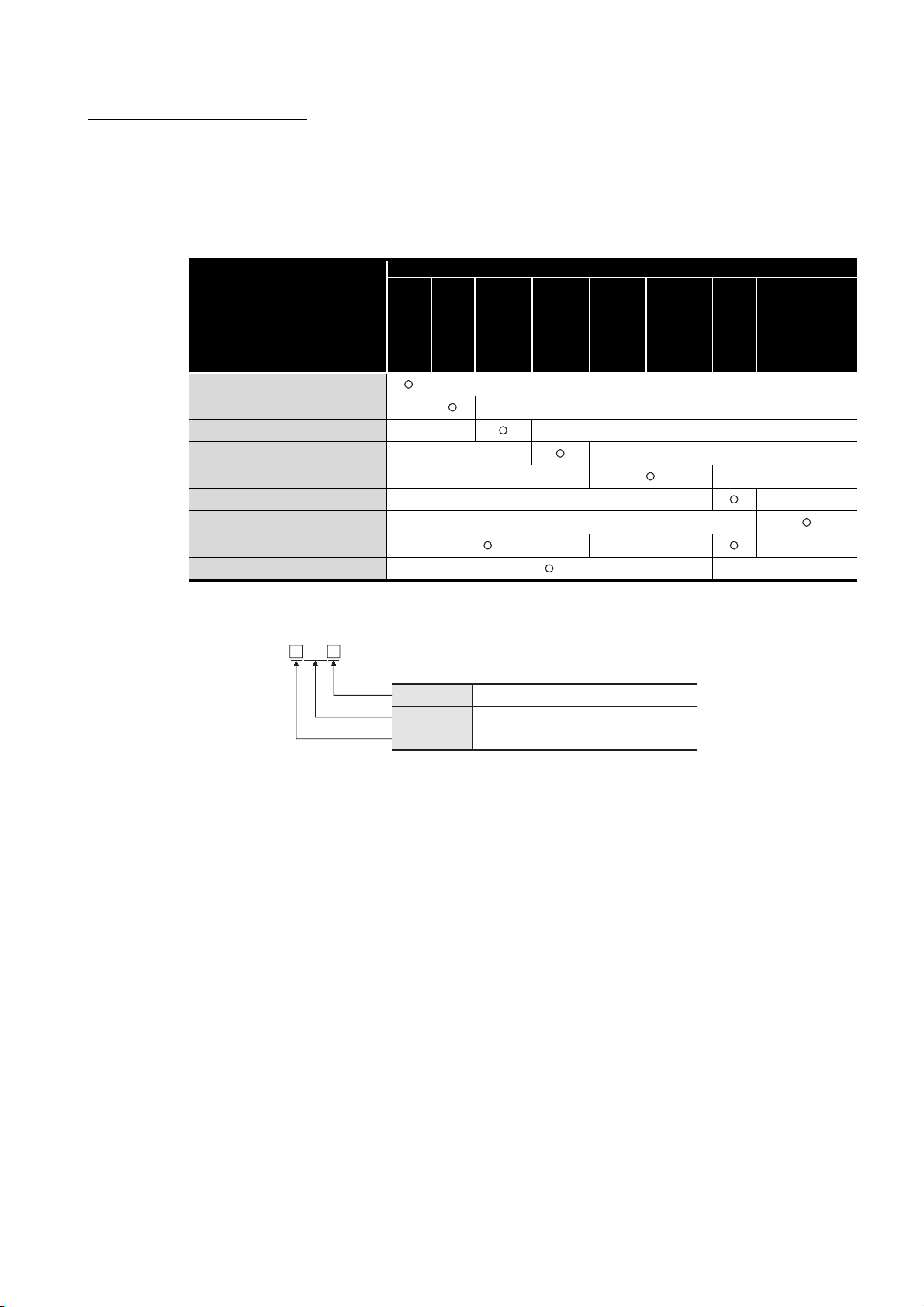
(1) Generic terms and abbreviations for CPU modules
Generic terms and abbreviations for
CPU modules
Basic model QCPU —
High Performance model QCPU — —
Process CPU — —
Redundant CPU — —
Universal model QCPU — —
Safety CPU — —
C Controller module —
Other than Universal model QCPU — —
Other than safety CPU —
Q00J
Q00
Q01
Q02
Q02H
Q06H
Q12H
Q25H
Q02PH
Q06PH
Q12PH
Q25PH
Q12PRH
Q25PRH
CPU model
Q02U
Q03UD
Q04UDH
Q06UDH
Q13UDH
Q26UDH
Q03UDE
Q04UDEH
Q06UDEH
Q13UDEH
Q26UDEH
QS001
Q06CCPU-V
Q06CCPU-V-B
(2) Networking station type codes
MP
Station No.
Abbreviation
Network No.
(Example)
• Network No.3, control station, station No.6 • • • 3MP6
• Network No.5, normal station, station No.3 • • • 5N
1 to 120
M
P: Control station, NS: Normal station
1 to 239
S3
A - 13
Page 16
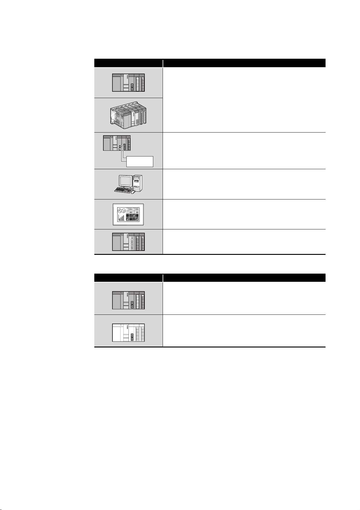
(3) Module illustration
Module illustration Description
External power
supply
CC-Link IE controller network module
CC-Link IE controller network module with external power supply
function
CC-Link IE controller network interface board
CC-Link IE controller network communication unit
(4) Module status
Module status Description
MELSECNET/H module
Normally operating station
Faulty station (Cyclic transmission is stopped.)
A - 14
Page 17

GENERIC TERMS AND ABBREVIATIONS
This manual describes the QJ71GP21-SX or QJ71GP21S-SX CC-Link IE controller
network module using the following generic terms and abbreviations, unless otherwise
specified.
Generic term and
abbreviation
Generic product name for SWnD5C-GPPW-E, SWnD5C-GPPW-EA, SWnD5C-GPPW-EV, and
GX Developer
CC-Link IE controller
network module
CC-Link IE controller
network module with
external power supply
function
CC-Link IE controller
network interface board
MELSECNET/H Abbreviation for the MELSECNET/H network system
MELSECNET/H module
MELSECNET/10 Abbreviation for the MELSECNET/10 network system
Data link Generic term for cyclic transmission and transient transmission
Network module Generic term for the CC-Link IE controller network module and MELSECNET/H module
Basic model QCPU Generic term for the Q00JCPU, Q00CPU, Q01CPU
High Performance model
QCPU
Process CPU Generic term for the Q02PHCPU, Q06PHCPU, Q12PHCPU, Q25PHCPU
Redundant CPU Generic term for the Q12PRHCPU, Q25PRHCPU
Universal model QCPU
Safety CPU Generic term for the QS001CPU
C Controller module Generic term for the Q06CCPU-V, Q06CCPU-V-B
READ Abbreviation for JP.READ or GP.READ
SREAD Abbreviation for JP.SREAD or GP.SREAD
WRITE Abbreviation for JP.WRITE or GP.WRITE
SWRITE Abbreviation for JP.SWRITE or GP.SWRITE
REQ Abbreviation for J.REQ, JP.REQ, G.REQ or GP.REQ
SEND Abbreviation for JP.SEND or GP.SEND
RECV Abbreviation for JP.RECV or GP.RECV
RECVS Abbreviation for Z.RECVS
ZNRD Abbreviation for J.ZNRD or JP.ZNRD
ZNWR Abbreviation for J.ZNWR or JP.ZNWR
RRUN Abbreviation for Z.RRUN or ZP.RRUN
RSTOP Abbreviation for Z.RSTOP or ZP.RSTOP
RTMRD Abbreviation for Z.RTMRD or ZP.RTMRD
RTMWR Abbreviation for Z.RTMWR or ZP.RTMWR
UINI Abbreviation for Z.UINI or ZP.UINI
SWnD5C-GPPW-EVA. ("n" means version 4 or later.)
"-A" and "-V" mean "volume license product" and "version-upgrade product" respectively.
Abbreviation for the QJ71GP21-SX or QJ71GP21S-SX CC-Link IE controller network module
Abbreviation for the QJ71GP21S-SX CC-Link IE controller network module
Abbreviation for the Q80BD-J71GP21-SX or Q80BD-J71GP21S-SX CC-Link IE controller
network interface board
Abbreviation for the QJ71LP21, QJ71LP21-25, QJ71LP21S-25, QJ71LP21G, QJ71LP21GE, or
QJ71BR11 MELSECNET/H network module
Generic term for the Q02CPU, Q02HCPU, Q06HCPU, Q12HCPU and Q25HCPU
Generic term for the Q02UCPU, Q03UDCPU, Q04UDHCPU, Q06UDHCPU, Q13UDHCPU,
Q26UDHCPU, Q03UDECPU, Q04UDEHCPU, Q06UDEHCPU, Q13UDEHCPU and
Q26UDEHCPU
Description
A - 15
Page 18

DEFINITIONS OF TERMINOLOGY
Definitions of the terms used in this manual are explained below.
Term Description
Using the link devices (LB/LW/LX/LY) of the CC-Link IE controller network module, data can be
Cyclic transmission
Transient transmission
Link dedicated instruction
CC-Link dedicated
instruction
RAS
Control station
Normal station
Reserved station
Relay station
Undefined station
Reconnection Processing of restarting data link when a faulty station becomes normal.
Disconnection Processing of stopping data link when a data link error occurs.
Device Devices (X, Y, M, D, etc.) that are contained in a CPU module.
Link device Devices (LB/LW/LX/LY) that are contained in a CC-Link IE controller network module.
Link scan time
Link refresh
Buffer memory Memory area in the CC-Link IE controller network module, in which data are temporarily stored.
Baton pass
Control station switching
time
Shared group No.
Group No.
transferred periodically between stations on the same network.
• LB/LW is used to send data of one station to all stations. (1:N communication)
• LX/LY is used to send data of one station to another station. (1:1 communication)
This function allows communication with another station when a request is made with a
dedicated instruction or from GX Developer.
Dedicated instruction that is used for transient transmission with other programmable
controllers.
Communications can be made with programmable controllers on the same or other networks.
Dedicated instruction that is used for transient transmission with CC-link IE controller network
compatible devices. This allows communication with a station on the same network.
Abbreviation for Reliability, Availability, and Serviceability.
This term is used to express the overall usability of automation systems.
Only one station that controls the network to which it is connected.
Each station's send range for cyclic transmission is assigned to the control station.
Station that performs cyclic transmission according to the range assignment of the control
station.
Station that is not actually connected to the network.
It must be included in the total number of stations in the network, since it is to be connected in
the future.
Station that relays transient transmission data to another network.
Link device data of a network module are transferred to another network module via this station.
Multiple network modules are connected to one programmable controller.
Station to which a station No. is to be set in the sequence program, however, that has presently
no station No. because the UINI instruction has not been executed yet.
Time required for data of each station to be sent in order and to make one rotation in the
network.
The link scan time changes depending on the data volume or transient transmission request.
Link scans are performed "asynchronously" with sequence scans of the CPU module.
Processing of data transfer between link devices of the CC-Link IE controller network module
and CPU module devices.
Link refresh is performed in "END processing" of the sequence scan of the CPU module.
A control mechanism in which transmission right (token) is passed around the network for data
transmission.
Time taken from when the control station went down due to a reason such as power-off until
data link is started by the sub-control station.
Number that is assigned to a station to allow it to share cyclic data with any given stations.
Cyclic data can be shared only with stations of the same group.
Number that is assigned for transient transmission to any given stations.
By specifying a group of stations as transient transmission target, data can be sent to the
stations of the same group No.
A - 16
Page 19

PAC K I NG LIST
The following is included in the package.
Model Product name Quantity
QJ71GP21-SX The QJ71GP21-SX CC-Link IE controller network module 1
QJ71GP21S-SX
The QJ71GP21S-SX CC-Link IE controller network module
(with external power supply function)
1
A - 17
Page 20
1
OVERVIEW
CHAPTER1 OVERVIEW
This manual provides information on the specifications, functions, preoperational
procedure, programming and troubleshooting of the QJ71GP21-SX and QJ71GP21S-SX
CC-Link IE controller network modules (hereinafter referred to as CC-Link IE controller
network module).
When applying a program example introduced in this manual to the actual system, make
sure to examine the applicability and confirm that it will not cause system control
problems.
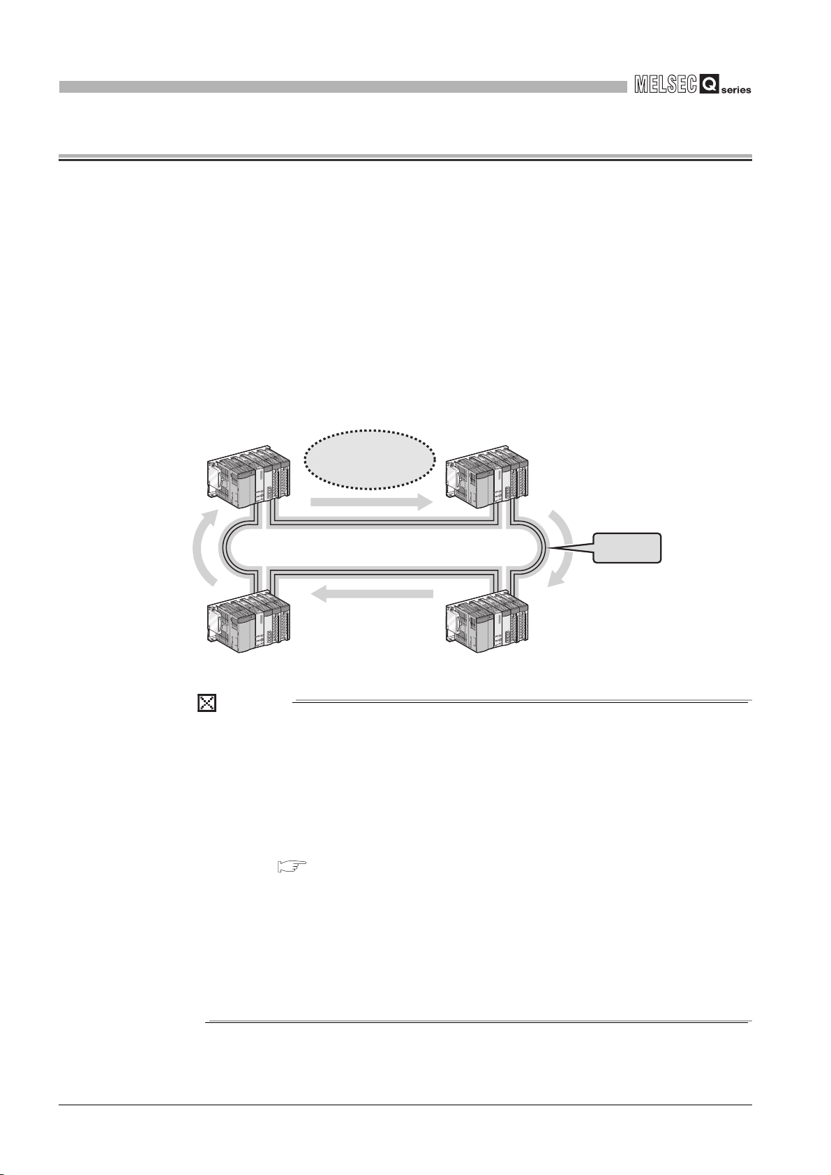
The CC-Link IE controller network module allows connection of MELSEC-Q series
programmable controllers to the CC-Link IE controller network, realizing high-speed and
large-volume data communications between the controllers in the network.
High-speed and
large-volume data
communications
CC-Link IE controller network
Figure 1.1 CC-Link IE controller network
Duplex loop
POINT
(1) The existing MELSECNET/G network module has been integrated into the
CC-Link IE controller network module.
(2) The CC-Link IE controller network is an improved system that has a higher
processing speed and a larger data capacity than the MELSECNET/H
network system (PLC to PLC network).
For comparisons between CC-Link IE controller network and MELSECNET/H,
refer to the following.
Appendix 4 Comparison between CC-Link IE controller network and
MELSECNET/H
(3) One network (of the same network No.) cannot contain both CC-Link IE
controller network and MELSECNET/H modules. (Different networks must be
used.)
• CC-Link IE controller network module: Used for CC-Link IE controller
network
• MELSECNET/H module: Used for MELSECNET/H or MELSECNET/10
1 - 1
Page 21
1
OVERVIEW
1.1 Features
1
This section explains the features of the CC-Link IE controller network module.
LB0
LB7FFF
LW0
LW1FFFF
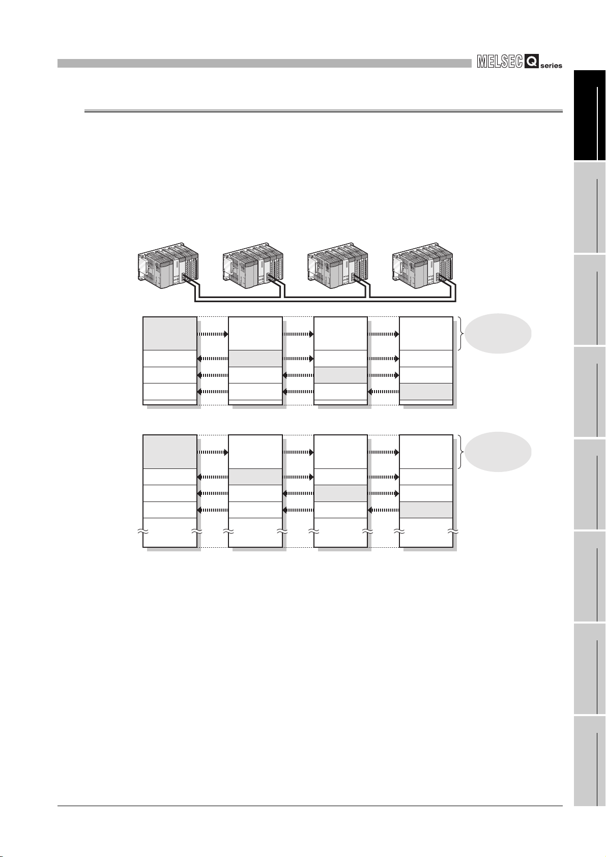
(1) Periodically exchanging large volumes of data (Cyclic transmission)
(a) Using link devices of the CC-Link IE controller network module allows periodical
exchange of large volumes of data between stations on the same network.
Control station
No.1
Link relay (LB)
No.1 send range
No.2
No.3
No.4
Link register (LW)
No.1 send range
No.2
No.3
No.4
Normal station
No.2
No.1 No.1 No.1
No.2 send range
No.3
No.4
No.1 No.1 No.1
No.2 send range
No.3
No.4
Figure 1.2 Cyclic transmission
Normal station
No.3
No.2
No.3 send range
No.4
No.2
No.3 send range
No.4
Normal station
No.4
Up to 16K link
points are available
per station.
No.2
No.3
No.4 send range
Up to 16K link
points are available
per station.
No.2
No.3
No.4 send range
OVERVIEW
2
SYSTEM
CONFIGURATION
3
SPECIFICATIONS
4
FUNCTIONS
5
PREPARATION AND
SETUP
6
1.1 Features
1 - 2
PARAMETER
7
8
SETTING
PROCESSING TIME
PROGRAMMING
Page 22
1
OVERVIEW
(b) Since a large number of modules and link points can be used in one network, a
large-scale network system can be constructed.
Also, when expanding the network, additional stations and send points can be
easily set up.
When control station is
Universal model QCPU
When control station is
other than Universal model QCPU
Link relay (LB)
Link register (LW)
Link input (LX)
Link output (LY)
(c) High-speed data communications are available at the speed of 1Gbps.
120 (Control station:1, Normal station: 119 *1)
64 (Control station: 1, Normal station: 63)*2
Figure 1.3 Number of stations per network
* 1 A Universal model QCPU can be set to station No.1 to 120.
Any other than Universal model QCPUs can be set to station No.1 to 64.
* 2 A Basic model QCPU or safety CPU operates as a normal station. (It cannot be set to a control
station.)
32K points (32768 points, 4KB)*3
128K points (131072 points, 256KB)*3
8K points (8192 points, 1KB)
8K points (8192 points, 1KB)
Figure 1.4 Maximum link points per network
* 3 For a Basic model QCPU or safety CPU, the link relay (LB) is 16K points (16384 points, 2KB) and
the link register (LW) is 16K points (16384 points, 32KB).
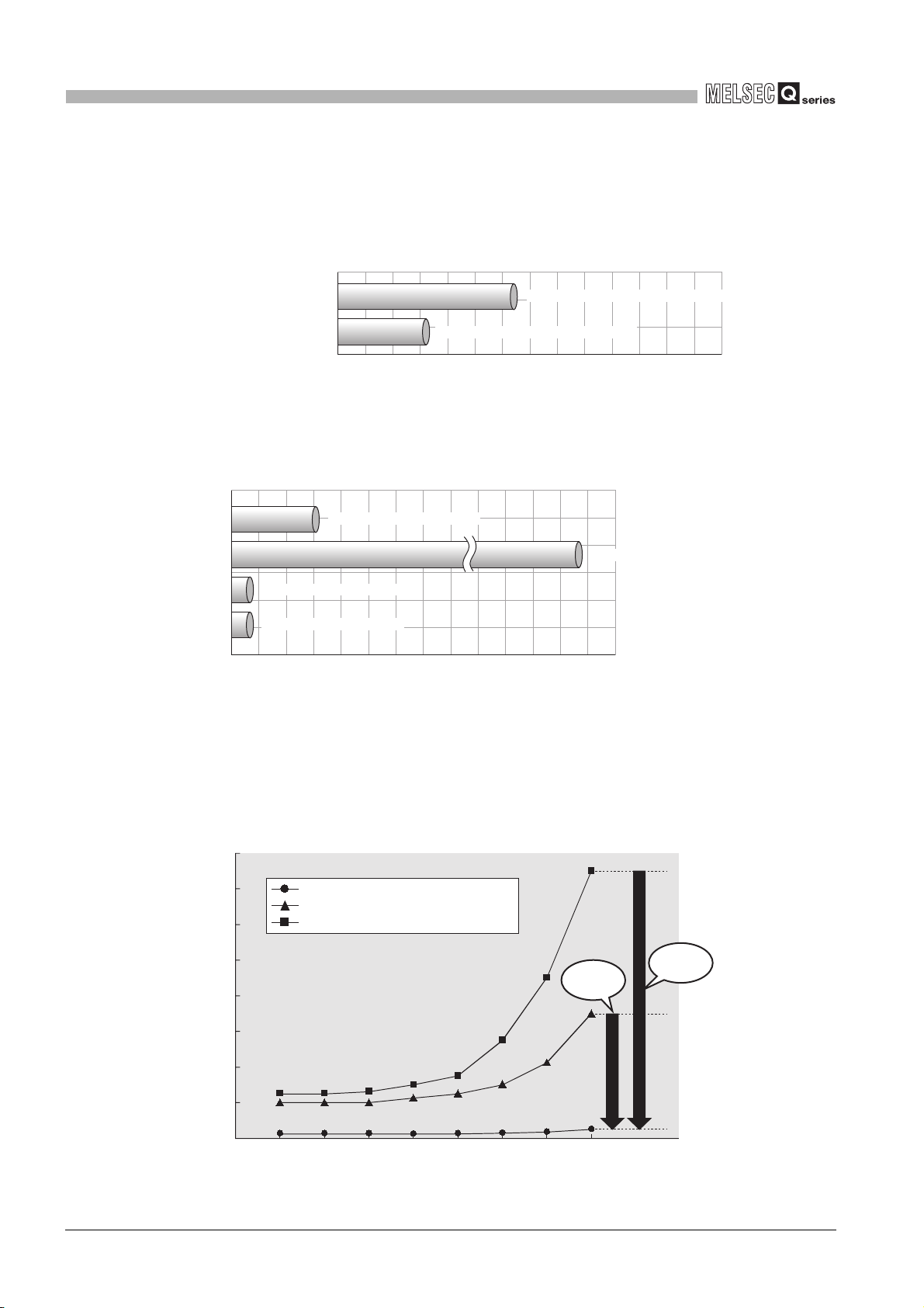
Because the link scan time and transmission delay time are short, applications for
production of a short takt time can be built.
(Example) Link scan time in the case where the number of stations in the network
is 32
1 - 3
160
120
80
Link scan time [ms]
40
0
1.1 Features
CC-Link IE controller network (1Gbps)
MELSECNET/H (25Mbps)
MELSECNET/10 (10Mbps)
1 2 4 8 16 32 64 1280
Link points per network [K bytes]
Figure 1.5 High-speed data communications
Approx.
1/14
Approx.
1/30
Page 23
1
OVERVIEW
(d) Automatic transfer is available between link devices of the CC-Link IE controller
network module and devices of a CPU module. (Link refresh)
For the Universal model QCPU, the extended link register (W) is useful for
transferring link register (LW) data that exceeds the link register (W) capacity (8K
points).
* 1 Models other than the Universal model QCPU do not have the extended link register (W).
*1
Use a file register instead.
1
OVERVIEW
2
[When using the extended link register as the transfer target CPU-side device]
Universal model QCPU
Extended link register
W0
MOV D0 W8000
MOV W8200 D1
Programming is easy because both
device numbers are hexadecimal.
[When using a file register as the transfer target CPU-side device]
MOV D0 ZR32768
MOV ZR33280 D1
W8000
W1FFFF
High Performance model QCPU
File register
ZR0
ZR32768
ZR33280
CC-Link IE controller
network module
Link register
LW0
LW8000
LW8200W8200
LW1FFFF
Link refresh
CC-Link IE controller
network module
Link register
LW0
LW8000
LW8200
SYSTEM
3
4
5
CONFIGURATION
SPECIFICATIONS
FUNCTIONS
Attention must be paid for programming
because decimal and hexadecimal device
numbers are used.
Figure 1.6 Link refresh
(e) With a sequence program, data can be directly read from or written to CC-Link IE
controller network module's link devices (LB/LW/LX/LY/SB/SW). (Direct access to
link devices)
For the Universal model QCPU, all of the link devices can be specified.
* 2 For models other than the Universal model QCPU, the area of address LB/LW4000 or higher
cannot be specified.
(f) Cyclic transmission punctuality can be ensured even at the time of transient
transmission (Cyclic transmission punctuality assurance).
Applications can be created without the need to consider link scan time
fluctuation.
ZR131071
Link refresh
1.1 Features
LW1FFFF
*2
1 - 4
PREPARATION AND
SETUP
6
PARAMETER
SETTING
7
PROCESSING TIME
8
PROGRAMMING
Page 24
1
OVERVIEW
Control station
No.1
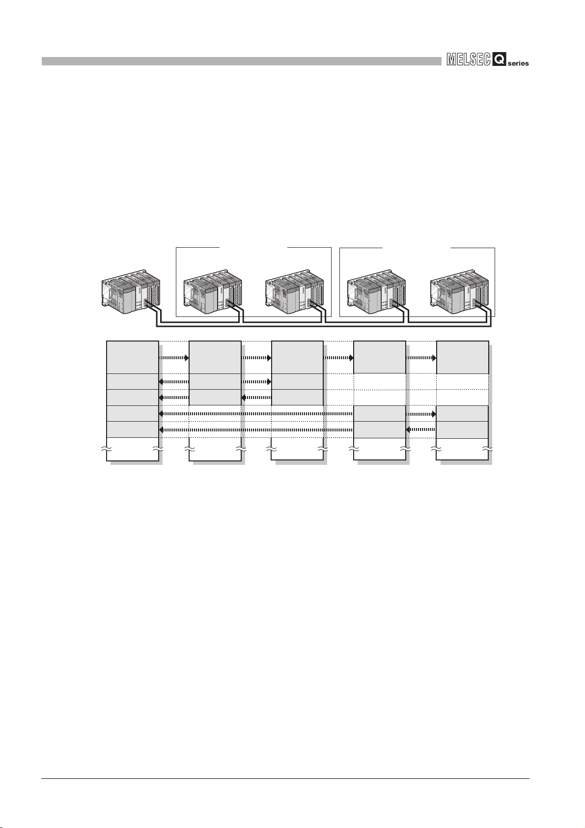
(g) Cyclic transmission is available only to any specific stations. (Group cyclic
transmission function)
A Universal model QCPU can share cyclic data with stations in the same shared
group.
This function is useful, for example, when sharing data among all stations that
integrates and controls production lines and not sharing the data with stations that
controls other machines.
Also, receiving cyclic data only from any specific stations can reduce the number
of link refresh points, resulting in a shorter link refresh time.
Shared group No.1 Shared group No.2
Normal station
No.2
Normal station
No.3
Normal station
No.4
Normal station
No.5
Link relay (LB)
LB0
No.1 send range No.1
No.2
No.3
No.4
No.5
LB7FFF
No.1
No.2 send range
No.3
Figure 1.7 Group cyclic transmission
No.1
No.2
No.3 send range
No.4 send range
No.5
No.1
No.4
No.5 send range
1 - 5
1.1 Features
Page 25
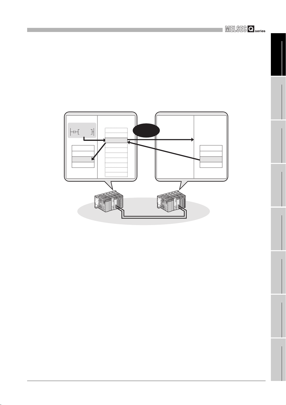
1
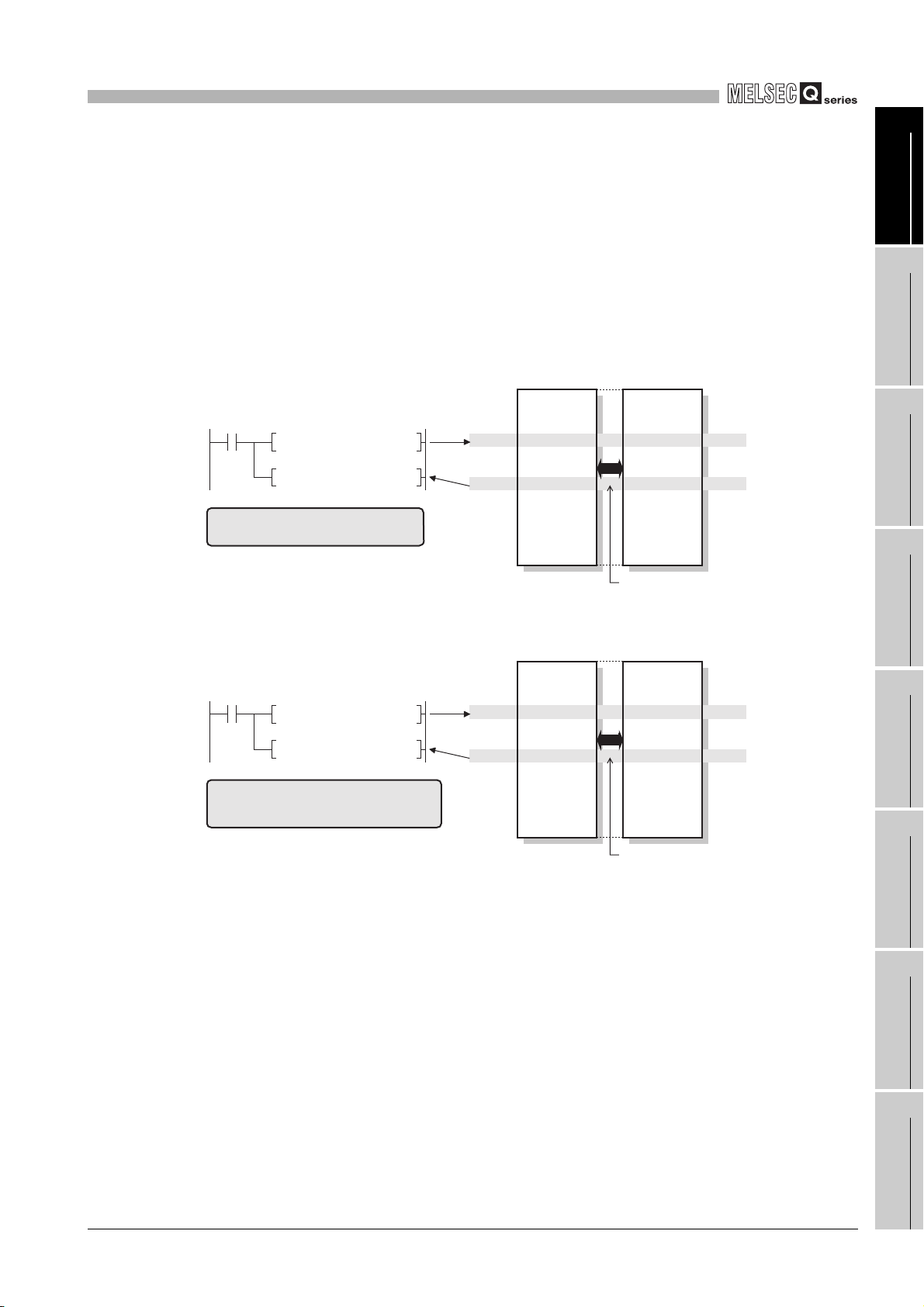
Word device
read request
OVERVIEW
(2) Communications with other stations' programmable controllers and
CPU module CPU moduleCC-Link IE controller
Command
READ
Device
1234
CC-Link IE controller network compatible devices (Transient
transmission)
(a) By using a link dedicated instruction, data can be read from or written to a
programmable controller on another station.
Note that communications with programmable controllers on other networks are
also available.
network module
Channel 1
Channel 2
Channel 3
Channel 4
Channel 5
H
Channel 6
Channel 7
Channel 8
Channel 9
Channel 10
Word device
read request
CC-Link IE controller
network module
Device
1234
H
1
2
SYSTEM
3
4
OVERVIEW
CONFIGURATION
SPECIFICATIONS
Figure 1.8 Communication with a programmable controller on another station by a link dedicated instruction
(b) Large-volume data can be transferred. (READ/SREAD/WRITE/SWRITE
instruction)
One link dedicated instruction execution can read or write data of up to 8192
words from or to a programmable controller on another station.
To specify 961 words or more, use channel 9 or 10 of the own station.
The instructions can be used for sending or receiving a large volume of data
irregularly.
FUNCTIONS
5
PREPARATION AND
SETUP
6
PARAMETER
SETTING
7
PROCESSING TIME
8
1.1 Features
PROGRAMMING
1 - 6
Page 26
1
Seamless
access
CC-Link IE
controller network
Reading
/writing data
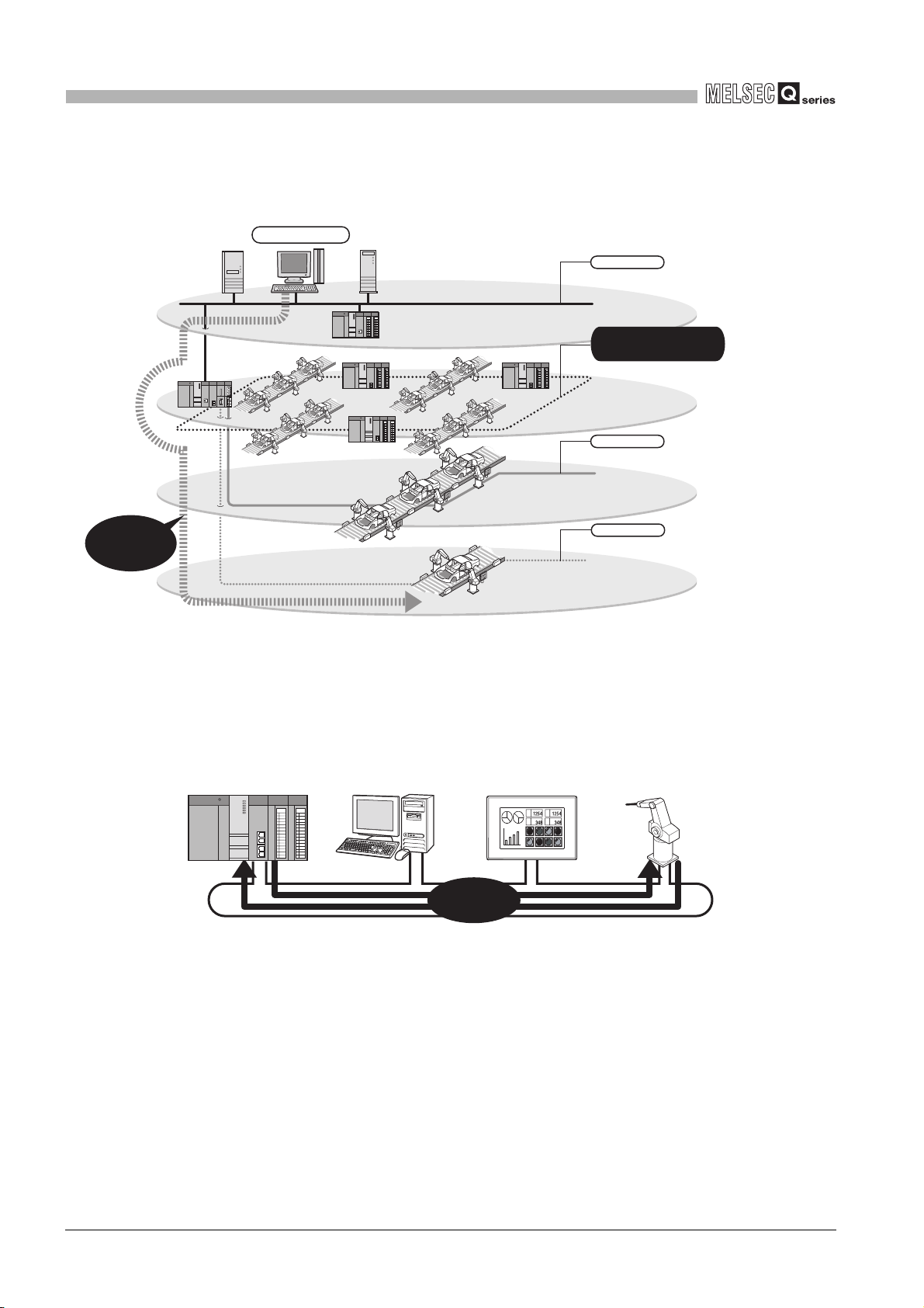
OVERVIEW
(c) Using GX Developer allows seamless access to the Ethernet, CC-Link IE
controller network, MELSECNET/H, MELSECNET/10, and CC-Link systems.
GX Developer
Ethernet
Intra-factory (Information management)
CC-Link IE
controller network
Inter-line (Production control)
CC-Link
Intra-line (Equipment control)
Seamless
access
Figure 1.9 Seamless access by GX Developer
CC-Link/LT
Individual sensor/actuator (Devices, I/O control)
(d) With a CC-Link dedicated instruction, data can be read from or written to CC-Link
IE controller network compatible devices.
Transient requests can be also received from CC-Link IE controller network
compatible devices.
Control station
No.1
Figure 1.10 Communication with CC-Link IE controller network compatible devices using CC-Link dedicated instructions
Normal station
No.2
Normal station
No.3
Reading
/writing data
Normal station
No.4
1 - 7
1.1 Features
Page 27
1
OVERVIEW
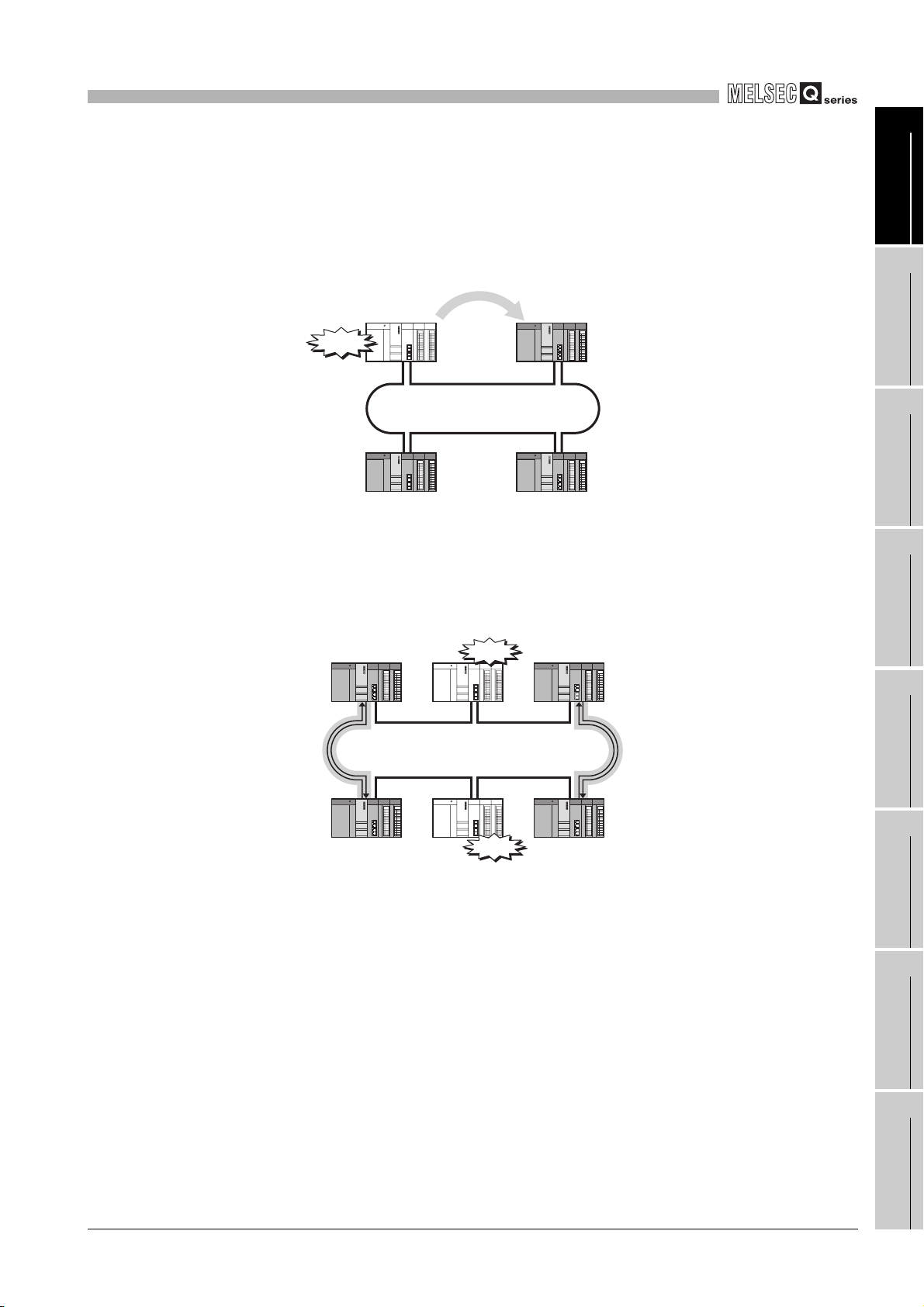
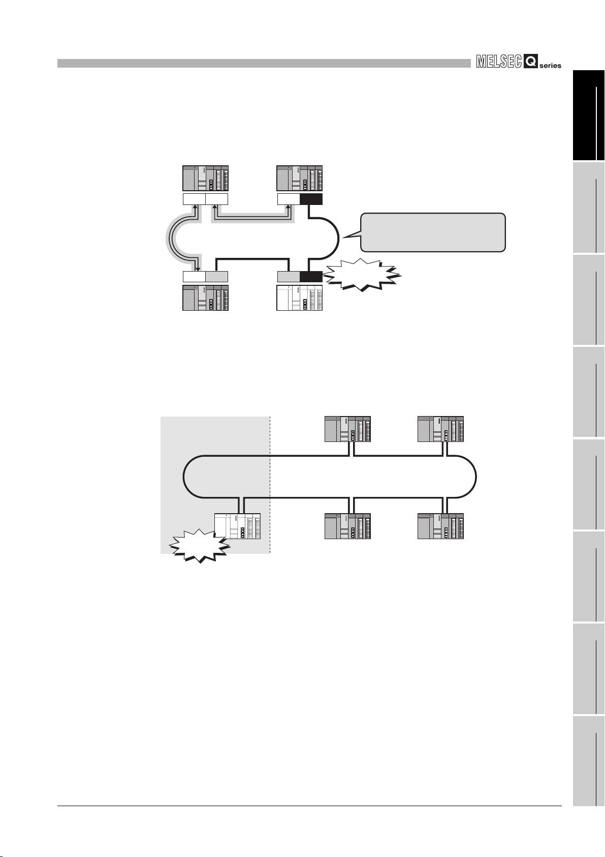
(3) Enriched RAS functions
(a) Even if the control station goes down, a normal station (sub-control station) will
take over the control to continue data link. (Control station switching function)
Switching
1
OVERVIEW
2
Control station
Down
Figure 1.11 Control station switching function
No.1
Normal station
No.4
Sub-control station
No.2
Normal station
No.3
(b) Any disconnected cable or faulty station can be isolated from the network, and
data link can be continued among normally operating stations. (Loopback
function)
Control station
No.1
Loopback station
Normal station
No.2
Down
Sub-control station
No.3
Loopback station
SYSTEM
3
4
5
CONFIGURATION
SPECIFICATIONS
FUNCTIONS
Normal station
No.6
Loopback station
Figure 1.12 Loopback function
Down
Normal station
No.5
Normal station
No.4
Loopback station
1.1 Features
1 - 8
PREPARATION AND
SETUP
6
PARAMETER
SETTING
7
PROCESSING TIME
8
PROGRAMMING
Page 28
1
OVERVIEW
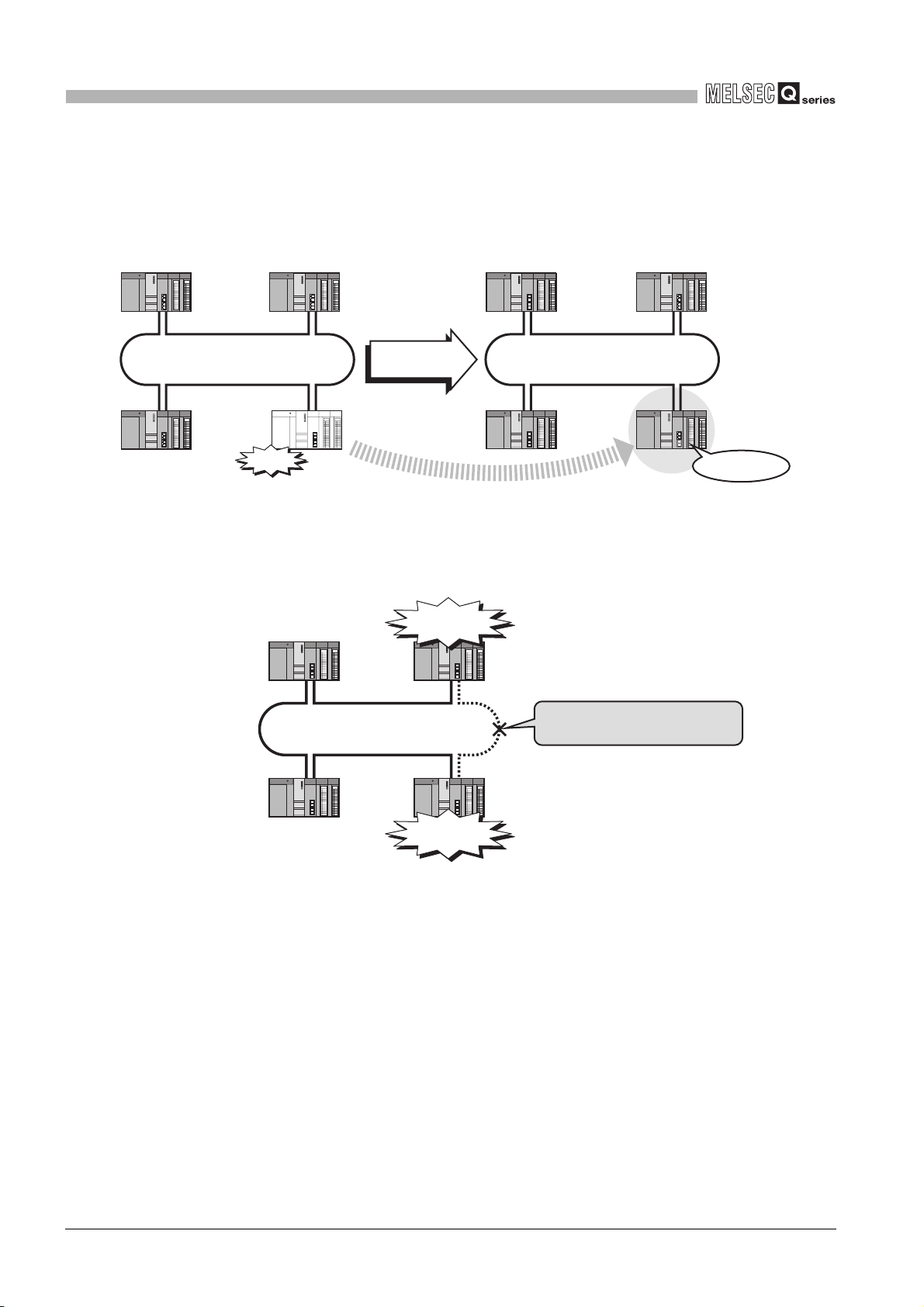
(c) When a station disconnected from a network due to a data link error recovers from
the error, the station is automatically reconnected to the network and restarts data
link. (Automatic return function)
This automatic return does not affect data link.
Control station
No.1
Normal station
No.4
Down
(d) A cable fault can be detected as a cause of a communication error. (Cable fault
Control station
No.1
Normal station
No.2
When recovered
from fault
Normal station
No.3
Figure 1.13 Automatic return function
detection function)
Communication
error
Normal station
No.2
A cable fault is detected as the
cause of the communication error.
Control station
No.1
Normal station
No.4
Normal station
No.2
Normal station
No.3
Reconnected
Normal station
No.4
Normal station
No.3
Communication
error
Figure 1.14 Cable fault detection function
1 - 9
1.1 Features
Page 29
1
OVERVIEW
Control station
No.1
(e) Incorrect cable connection between OUT and IN can be detected as a cause of
loopback or disconnection from the network. (Cable insertion error detection
function)
Normal station
No.2
OUTIN OUTIN
Incorrect cable connection between
OUT and IN is detected as the cause
of the loopback and disconnection.
INOUT OUTIN
Cable
insertion error
1
2
SYSTEM
3
OVERVIEW
CONFIGURATION
Normal station
No.4
Normal station
No.4
Normal station
No.3
Figure 1.15 Cable insertion error detection function
(f) Duplication of the control station or station No. can be detected as a cause of
loopback or disconnection from the network. (Detection of duplicated control
station or station No.)
(Example) When a station is added to a network (Station No. duplication)
Control station
No.1
When a normal
station of a duplicated
No. is added
Normal station
No.4
Station No.
duplicated
Figure 1.16 Detection of duplicated control station or station No.
Stations No.1 to No.4 continues
cyclic transmission.
Normal station
No.2
Normal station
No.3
SPECIFICATIONS
4
FUNCTIONS
5
PREPARATION AND
SETUP
6
1.1 Features
1 - 10
PARAMETER
7
8
SETTING
PROCESSING TIME
PROGRAMMING
Page 30
1
OVERVIEW
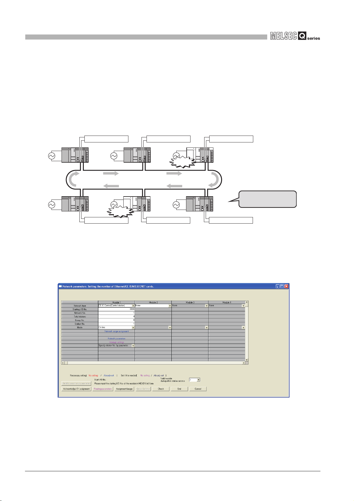
(g) The external power can be directly supplied to the CC-Link IE controller network
module with external power supply function. (External power supply function)
Even if a CPU module power goes down in a network, data link will be continued
among normally operating stations without being disrupted at the power-down
station. (Loopback does not occur.)
Data link is also continued between failed stations when power failure has
occurred on CPU modules on multiple stations.
External power supply
Control
station
No.1
Normal
station
No.6
External power supply External power supply External power supply
Down
Figure 1.17 External power supply function
External power supply External power supply
Normal
station
No.2
Normal
station
No.5
Down
Normal
station
No.3
Normal
station
No.4
Data link is continued
between failed stations.
(4) Simple network parameter setting using GX Developer
Network parameters required for network construction can be easily set up with GX
Developer.
1 - 11
Figure 1.18 Network parameters in GX Developer
1.1 Features
Page 31

1
OVERVIEW
(5) Network diagnostics with GX Developer
The network status or each station's operating status can be checked by the CC IE Control
Network Diagnostics. By using this, even if an error occurs at system startup or during
operation, troubleshooting can be done easily.
OUT-side cable
disconnection
Control station
No.1
Normal station
No.2
1
2
SYSTEM
3
4
OVERVIEW
CONFIGURATION
SPECIFICATIONS
GX Developer
Normal station
No.4
Figure 1.19 CC IE Control Network Diagnostics in GX Developer
Normal station
No.3
IN-side cable
disconnection
FUNCTIONS
5
PREPARATION AND
SETUP
6
PARAMETER
SETTING
7
PROCESSING TIME
8
1.1 Features
PROGRAMMING
1 - 12
Page 32

1
OVERVIEW
(6) Redundant system construction is available. (Compatibility with
redundant CPUs)
(a) System redundancy using CC-Link IE controller network modules can be
designed.
By mounting a CC-Link IE controller network module to each of base units with
redundant CPUs, a redundant system can be configured.
If an error occurs in the control system CPU or CC-Link IE controller network
module, the control and standby systems will be switched each other, and the
standby system will take over the system control and data link.
(b) System switching request can be issued to the control system CPU.
When the CC-Link IE controller network module of the control system CPU
detects a data link error, it can issue a system switching request to the control
CPU.
(c) Transient transmission to a redundant system is executable.
With a link dedicated instruction or from GX Developer, device data can be read
from or written to its own system, control/standby system, system A/B of a
redundant system, and remote RUN/STOP can be controlled.
By specifying the target station's CPU type to Control or Standby system, the
target can be fixed even if a system switching occurs.
CC-Link IE controller
network module
Control
station No.3
CC-Link IE controller network
Control system Standby system
Normal
station No.1
Tracking cable
Figure 1.20 Redundant system
Normal
station No.4
Normal
station No.2
1 - 13
1.1 Features
Page 33

1
OVERVIEW
(7) Common project data can be created for normal stations
GX Developer
For normal
For Universal model QCPUs, the station No. of a normal station (own station) can be
set in the sequence program.
*1
If there are any normal stations that can share the same sequence program and
network parameters (except for station No.), specifying their station numbers in the
sequence program creates common project data for them, allowing easy data
management.
* 1 For modules other than Universal model QCPUs, station No. cannot be set in sequence programs.
Station Nos. must be set with network parameters.
For control
station
stations
Common project data can be created for
normal stations, resulting in easy management.
1
2
SYSTEM
3
OVERVIEW
CONFIGURATION
For control
station
For normal
stations
Station No. setting by
sequence program
Figure 1.21 Creating common project data for normal stations
Station No. setting by
sequence program
For normal
stations
Control
station
No.1
Normal
station
No.6
For normal
stations
Station No. setting by
sequence program
Station No. setting by
sequence program
For normal
stations
Normal
station
No.2
Normal
station
No.5
For normal
stations
Station No. setting by
sequence program
Normal
station
No.3
Normal
station
No.4
SPECIFICATIONS
4
FUNCTIONS
5
PREPARATION AND
SETUP
6
PARAMETER
SETTING
7
1.1 Features
PROCESSING TIME
8
PROGRAMMING
1 - 14
Page 34

2
SYSTEM CONFIGURATION
CHAPTER2 SYSTEM CONFIGURATION
This chapter describes system configurations for the CC-Link IE controller network
module.
2.1 CC-Link IE Controller Network Configurations
2.1.1 Single network system
The single network system is a system that consists of a control station and normal
stations, which are connected with optical fiber cables.
CC-Link IE controller
network module
Control station
Station No.1
Figure 2.1 Single network system
* 1 A personal computer equipped with a CC-Link IE controller network interface board can be
connected as a control or normal station of the CC-Link IE controller network.
For details on the CC-Link IE controller network interface board, refer to the following manual.
CC-Link IE controller network interface board User's Manual
* 2 By connecting a CC-Link IE controller network module to a GOT, the GOT can be connected to the
CC-Link IE controller network as a normal station.
For details on the CC-Link IE controller network communication unit, refer to the following manual.
GT15 User's Manual
Normal station
Station No.2
CC-Link IE controller network
interface board
Optical fiber cable
*1
Normal station
Station No.3
CC-Link IE controller network
communication unit
*2
Normal station
Station No.120
POINT
One network (of the same network No.) cannot contain both CC-Link IE controller
network and MELSECNET/H modules. (Different networks must be used.)
• CC-Link IE controller network module: Used for CC-Link IE controller
network
• MELSECNET/H module: Used for MELSECNET/H or MELSECNET/10
2 - 1
2.1 CC-Link IE Controller Network Configurations
2.1.1 Single network system
Page 35

2
SYSTEM CONFIGURATION
(1) When Universal model QCPU is used for control station
Up to 120 stations including one control station and 119 normal stations can be
connected. (One control station is needed for a single network.)
Table 2.1 When Universal model QCPU is used for control station
High Performance
Item
Network type Normal station
Station No. Station No.1 to 64 Station No.1 to 120
*1
*1
*2
Section 4.1.1 (5) Receive range for other stations' data
Section 4.1.2 (5) Receive range for other stations' data
Link device
range
Link relay (LB)
Link register (LW)
Link input (LY)
Link output (LY) LY0 to 1FFF
Link special relay (SB) SB0 to 1FF
Link special register (SW) SW0 to 1FF
* 1 The receive range for other station's data varies depending on the CPU module.
* 2 The receive range for other station's data varies depending on the CPU module.
Basic model QCPU
Safety CPU
LB0 to 3FFF LB0 to 7FFF
LW0 to 3FFF LW0 to 1FFFF
model QCPU
Process CPU
Redundant CPU
LX0 to 1FFF
Universal model
Control station and
normal station
QCPU
1
2
SYSTEM
3
4
OVERVIEW
CONFIGURATION
SPECIFICATIONS
(2) When other than Universal model QCPU is used for control station
Up to 64 stations including one control station and 63 normal stations can be
connected. (One control station is needed for a single network.)
Table 2.2 When other than Universal model QCPU is used for control station
High Performance
Item
Network type
Station No. Station No.1 to 64
*1
*1
*2
Section 4.1.1 (5) Receive range for other stations' data
Section 4.1.2 (5) Receive range for other stations' data
Link device
range
Link relay (LB)
Link register (LW)
Link input (LY)
Link output (LY) LY0 to 1FFF
Link special relay (SB) SB0 to 1FF
Link special register (SW) SW0 to 1FF
* 1 The receive range for other station's data varies depending on the CPU module.
* 2 The receive range for other station's data varies depending on the CPU module.
* 3 A station with a Basic model QCPU or safety CPU operates as a normal station. (It cannot be set to
a control station.)
Basic model QCPU
Safety CPU
Normal station
LB0 to 3FFF LB0 to 7FFF
LW0 to 3FFF LW0 to 1FFFF
*3
model QCPU
Process CPU
Redundant CPU
Control station and
normal station
LX0 to 1FFF
Universal model
QCPU
Normal station
FUNCTIONS
5
PREPARATION AND
SETUP
6
PARAMETER
SETTING
7
PROCESSING TIME
8
2.1 CC-Link IE Controller Network Configurations
2.1.1 Single network system
PROGRAMMING
2 - 2
Page 36

2
SYSTEM CONFIGURATION
2.1.2 Redundant system
A redundant system is a system in which a basic system including a CPU module, a power
supply module, a network module is backed up with the other system.
By mounting a CC-Link IE controller module to each main base unit of a redundant CPU,
two CC-Link IE controller network modules can be used in a redundant system.
For use with redundant CPUs, refer to the following.
Section 4.6 Redundant-CPU-Compatible Function
CC-Link IE controller
network module
Control
station No.3
CC-Link IE controller network
Normal
station No.4
Control system Standby system
Normal
station No.1
Tracking cable
Figure 2.2 Redundant system
Normal
station No.2
2 - 3
2.1 CC-Link IE Controller Network Configurations
2.1.2 Redundant system
Page 37

2
SYSTEM CONFIGURATION
2.1.3 Multi-network system
The multi-network system is a system in which multiple networks are connected by some
relay stations.
Up to 239 networks can be connected.
1
OVERVIEW
2
Control
station
P
1M
Normal station
S
3
1N
CC-Link IE controller
network module
1
CC-Link IE controller network
Network No.1
Control station
P
1
3M
Normal station
S
2
3N
Figure 2.3 Multi-network system
Normal
station
1NS2
MELSECNET/H Network No.3
Control
station
2MP1
Normal station
3NS3
MELSECNET/H
module
MELSECNET/H Network No.2
Normal station
Normal station
3NS4
Normal
station
2NS2
S
2N
SYSTEM
CONFIGURATION
3
SPECIFICATIONS
4
3
FUNCTIONS
5
Regardless of single or multiple CPU system, one system can contain up to four CC-Link
IE controller network modules (up to four including MELSECNET/H module(s)).
* 1 Depending on the CPU module to be used, there are restrictions on the number of modules that
can be installed to one system.
Section 2.3 Applicable Systems
2nd
1st
3rd
4th
CC-Link IE controller network
network No.1
CC-Link IE controller network
network No.2
Figure 2.4 Number of mountable modules per system
2.1 CC-Link IE Controller Network Configurations
MELSECNET/H
network No.4
MELSECNET/H
network No.3
2.1.3 Multi-network system
*1
2 - 4
PREPARATION AND
SETUP
6
PARAMETER
SETTING
7
PROCESSING TIME
8
PROGRAMMING
Page 38

2
SYSTEM CONFIGURATION
2.2 Network Components
The CC-Link IE controller network consists of the following.
2.2.1 Order of optical fiber cables (Optional)
Optical fiber cables with connectors are available from Mitsubishi Electric System &
Service Co., Ltd. (Catalogs of the optical fiber cables are also available.)
In addition, on-site connector polishing, terminal assembly, and fusion splicing is available.
Please consult your local Mitsubishi Electric System & Service representative.
Typ e Model (Manufacturer)
Multi-mode fiber (GI) QG series (Mitsubishi Electric System & Service Co., Ltd.)
POINT
(1) For CC-Link IE controller network modules, 2-core cables are used.
(2) Optical fiber cables used for MELSECNET/H modules or MELSECNET/10
modules cannot be used for CC-Link IE controller network modules.
Table 2.3 Optical fiber cable
Remark
(1) The following types of optical fiber cables are available.
A type: Cable for connection inside control panel
B type: Cable for connection between control panels inside a building
C type: Cable for outdoor connection
D type: Reinforced cable for outdoor connection
There are special cables available for moveable applications and resistance
to heat. Contact your Mitsubishi Electric System & Service for details.
2 - 5
2.2 Network Components
2.2.1 Order of optical fiber cables (Optional)
Page 39

2
SYSTEM CONFIGURATION
2.2.2 CC-Link IE controller network interface board
The CC-Link IE controller network interface boards designed for use in a personal
computer are shown below.
For details on the CC-Link IE controller network interface boards, refer to the following
manual.
CC-Link IE controller network interface board User's Manual
Table 2.4 CC-Link IE controller network interface boards
Model Product name Network type
Q80BD-J71GP21-SX Q80BD-J71GP21-SX CC-Link IE controller network interface board
Q80BD-J71GP21S-SX
2.2.3 CC-Link IE controller network communication unit
Q80BD-J71GP21S-SX CC-Link IE controller network interface board
(with external power supply function)
CC IE Control (Control station)
CC IE Control (Normal station)
1
2
SYSTEM
3
OVERVIEW
CONFIGURATION
The CC-Link IE controller network communication unit used for the GOT is shown below.
For details on the CC-Link IE controller network communication unit, refer to the following
manual.
GT15 User's Manual
Table 2.5 CC-Link IE controller network communication unit
Model Product name Network type
GT15-J71GP23-SX CC-Link IE controller network communication unit CC IE Control (Normal station)
SPECIFICATIONS
4
FUNCTIONS
5
PREPARATION AND
SETUP
6
PARAMETER
SETTING
7
2.2 Network Components
2.2.2 CC-Link IE controller network interface board
PROCESSING TIME
8
PROGRAMMING
2 - 6
Page 40

2
SYSTEM CONFIGURATION
2.3 Applicable Systems
This section describes the applicable systems.
The number of mountable modules represents the maximum number of CC-Link IE
controller network modules that can be used together with MELSECNET/H modules.
(1) Applicable modules and base units, and No. of modules
(a) When mounted with a CPU module
The table below shows the CPU modules and base units applicable to the
CC-Link IE controller network module and quantities for each CPU model.
Depending on the combination with other modules or the number of mounted
modules, power supply capacity may be insufficient.
Pay attention to the power supply capacity before mounting modules, and if the
power supply capacity is insufficient, change the combination of the modules.
Table 2.6 Applicable CPU modules and base units, and No. of modules
Applicable CPU module
CPU type CPU model CPU module version
Basic model
QCPU
High Performance
model QCPU
Process CPU
Programmable
controller CPU
C Controller module
Redundant CPU
Universal model
QCPU
Safety CPU QS001CPU
Q00JCPU
Q00CPU
Q01CPU
Q02CPU
Q02HCPU
Q06HCPU
Q12HCPU
Q25HCPU
Q02PHCPU
Q06PHCPU
Q12PHCPU
Q25PHCPU
Q12PRHCPU
Q25PRHCPU
Q02UCPU
Q03UDCPU
Q04UDHCPU
Q06UDHCPU
Q13UDHCPU
Q26UDHCPU
Q03UDECPU
Q04UDEHCPU
Q06UDEHCPU
Q13UDEHCPU
Q26UDEHCPU
Q06CCPU-V
Q06CCPU-V-B N/A
Function version B or
later
First 5 digits of Serial
No. is 09012 or later.
From the first product
First 5 digits of Serial
No. is 10042 or later.
First 5 digits of Serial
No. is 10042 or later.
First 5 digits of Serial
No. is 09042 or later.
First 5 digits of Serial
No. is 09042 or later.
From the first product
First 5 digits of Serial
No. is 10032 or later.
First 5 digits of Serial
No. is 10012 or later.
No. of modules
*3
1
*4
2
*4
2
*5
2
*6
2
*6
4
*3
1
*6
4
*1
Base unit
Main base
unit
*2
Extension
base unit
*7
2 - 7
: Applicable, : N/A
2.3 Applicable Systems
Page 41

2
SYSTEM CONFIGURATION
* 1 Limited within the range of I/O points for the CPU module.
* 2 Can be installed to any I/O slot of a base unit.
* 3 For use with a Basic model QCPU or safety CPU:
Use a CC-Link IE controller network module of function version D or later.
* 4 For use with a High Performance model QCPU or Process CPU when total number of stations in a
network is 65 or more:
Use a CC-Link IE controller network module whose serial No. (first five digits) is 09042 or later.
* 5 For use with redundant CPUs:
It shows the number of modules that can be mounted to one of the two systems.
Use a CC-Link IE controller network modules of function version D or later.
* 6 For use with a Universal model QCPU or C Controller module:
Use a CC-Link IE controller network module whose serial No. (first five digits) is 09042 or later.
* 7 Connection of extension base units is not available with any safety CPU.
Remark
When using with a C Controller module, refer to the following manual.
C Controller Module User's Manual
1
2
SYSTEM
3
OVERVIEW
CONFIGURATION
(b) Mounting to a MELSECNET/H remote I/O station
The CC-Link IE controller network module cannot be mounted to any
MELSECNET/H remote I/O station.
Mount it to a CPU module on a master station.
SPECIFICATIONS
4
FUNCTIONS
5
PREPARATION AND
SETUP
6
PARAMETER
SETTING
7
2.3 Applicable Systems
PROCESSING TIME
8
PROGRAMMING
2 - 8
Page 42

2
SYSTEM CONFIGURATION
(2) Support of the multiple CPU system
When using the CC-Link IE controller network module in the multiple CPU system,
refer to the following manual first.
QCPU User's Manual (Multiple CPU System)
(a) Applicable CC-Link IE controller network module
The function version of the CC-Link IE controller network module has been "B"
from the first release and it supports the multiple CPU system.
(b) Network parameters
Network parameters must be set to the control CPU of the CC-Link IE controller
network module.
(3) Software package
Systems using the CC-Link IE controller network module and software package are
shown below.
To use the CC-Link IE controller network module, GX Developer is required.
System configuration
Q00J/Q00/Q01CPU
Q02/Q02H/Q06H/Q12H/Q25HCPU
Q02PH/Q06PH/Q12PH/Q25PHCPU
Q12PRH/Q25PRHCPU Redundant system Version 8.68W or later
Q02U/Q03UD/Q04UDH/Q06UDHCPU
Q13UDH/Q26UDHCPU
Q03UDE/Q04UDEH/Q06UDEH/
Q13UDEH/Q26UDEHCPU
QS001CPU Single CPU system
Table 2.7 Software package
Single CPU system
Multiple CPU system
Single CPU system
Multiple CPU system
Single CPU system
Multiple CPU system
Single CPU system
Multiple CPU system
Single CPU system
Multiple CPU system
Single CPU system
Multiple CPU system
Software version
GX Developer
Version 8.68W or later
Version 8.45X or later
Version 8.68W or later
Version 8.48A or later
Version 8.62Q or later
Version 8.68W or later
Version 8.65T or later
*1
*2
*2
*2
*2
2 - 9
* 1 For GX Developer versions that support a functional upgrade of CC-Link IE controller network,
refer to the following.
Appendix 3 Functional Upgrade of CC-Link IE controller network
* 2 When using a GX Developer Version earlier than 8.68W, please interpret the description of
"MELSECNET/G" as "CC-Link IE controller network".
2.3 Applicable Systems
Page 43

2
SYSTEM CONFIGURATION
2.4 Checking the Function Version and Serial No.
This section explains how to check the function version and serial No. of the CC-Link IE
controller network module.
(1) Checking the "Rating plate" on the side of the module
The serial No. and function version of the module are printed in the SERIAL section of
the rating plate.
Serial No. (first 5 digits)
Function version
09042 B
Relevant regulation standards
Figure 2.5 Rating plate
1
2
SYSTEM
3
4
OVERVIEW
CONFIGURATION
SPECIFICATIONS
(2) Checking through GX Developer
The following explains how to check the serial No. and function version of the module
through GX Developer.
The serial No. and function version are displayed on the "Product Information List" or
"Module's Detailed Information" screen of GX Developer.
The procedure for checking the serial No. and function version on the "Product
Information List" screen is shown below.
[Operation procedure]
[Diagnostics] [System Monitor] [Product Information List]
FUNCTIONS
5
PREPARATION AND
SETUP
6
PARAMETER
SETTING
7
Figure 2.6 Product Information List
2.4 Checking the Function Version and Serial No.
PROCESSING TIME
8
PROGRAMMING
2 - 10
Page 44

2
SYSTEM CONFIGURATION
[Serial No., Ver. and Product No.]
• The serial No. of the module is displayed in the "Serial No." column.
• The function version of the module is displayed in the "Ver." column.
• The serial No. (Product No.) printed on the rating plate is displayed in the
"Product No." column.
For a module that does not support the Product No. display, "-" is displayed.
* 1 The Product No. appears only when the CPU module is a Universal model QCPU.
* 2 Check the serial No. and software version.
Appendix 3 Functional Upgrade of CC-Link IE controller network
POINT
The serial No. shown on the rating plate may not match the one displayed in the
Product Information List of GX Developer.
• The serial No. on the rating plate indicates the management information
of the product.
• The serial No. displayed in the Product Information List of GX Developer
indicates the functional information of the product.
The functional information of the product is updated when a new function
is added.
*1
2 - 11
2.4 Checking the Function Version and Serial No.
Page 45

3
SPECIFICATIONS
CHAPTER3 SPECIFICATIONS
This chapter describes the performance specifications and function lists of the CC-Link IE
controller network module.
For general specifications, refer to the following manual.
QCPU User's Manual (Hardware Design, Maintenance and Inspection)
3.1 Performance Specifications
The performance specifications of the CC-Link IE controller network module are shown
below.
Table 3.1 Performance specifications
Item
LB
Max. link points per
network
Max. link points per
station
Transient transmission capacity Up to 1920 bytes
Communication speed 1Gbps
Number of stations per network
Connection cable
Overall cable distance 66000m (When 120 stations are connected)
Station-to-station distance (Max.)
Max. number of networks 239
Max. number of groups 32
Transmission path Duplex loop
Optical fiber specifications 1000BASE-SX(MMF) optical fiber cable
Standard
Transmission loss
(max.)
Transmission band
(min.)
Connector specifications Duplex LC connector
Standard IEC61754-20: Type LC connector
Connection loss 0.3 (dB) or less
Polished surface PC (Physical Contact) polishing
Number of occupied I/O points 32 (Intelli.: 32 points) *3
LW
LX 8K points (8192 points, 1KB)
LY 8K points (8192 points, 1KB)
LB 16K points (16384 points, 2KB)
LW 16K points (16384 points, 32KB)
LX 8K points (8192 points, 1KB)
LY 8K points (8192 points, 1KB)
32K points (32768 points, 4KB)
(Basic model QCPU or safety CPU: 16K points (16384 points, 2KB))
128K points (131072 points, 256KB)
(Basic model QCPU or safety CPU: 16K points (16384 points, 32KB))
When Universal model QCPU is used for control station: 120
(Control station: 1, Normal station: 119) *1
When any other than Universal model QCPU is used for control station: 64
(Control station: 1, Normal station: 63) *2
Optical fiber cable (Multi-mode fiber) ( Section 2.2.1 Order of optial fiber cables (Optional))
550m (Core/Clad = 50/125 ( m))
IEC60793-2-10 Types A1a.1(50/125 m multimode)
3.5 (dB/km) or less ( = 850nm)
500 (MHz•km) or more ( = 850nm)
QJ71GP21-SX QJ71GP21S-SX
Specification
48 (I/O assignment: Empty first half: 16 points,
Latter half: 32 points for intelli.) *3 *4
1
OVERVIEW
2
SYSTEM
CONFIGURATION
3
SPECIFICATIONS
4
FUNCTIONS
5
PREPARATION AND
SETUP
6
PARAMETER
SETTING
7
PROCESSING TIME
8
3.1 Performance Specifications
PROGRAMMING
3 - 1
Page 46

3
SPECIFICATIONS
Table 3.1 Performance specifications (Continued)
Item
Voltage
Current 0.28A
Terminal screw size M3
Applicable solderless
External
power supply
Internal current consumption (5V DC) 0.85A 0.90A
External dimensions 98 (H) x 27.4 (W) x 90 (D) [mm] 98 (H) x 55.2 (W) x 90 (D) [mm]
Weight 0.18kg 0.28kg
terminal
Applicable wire size
Tightening torque 0.42 to 0.58N•m
Allowable momentary
power failure time
Noise immunity
No external power supply function
* 1 A Universal model QCPU can be set to a station No. within the range of No.1 to No.120.
For a module other than Universal model QCPUs, station No.1 to No.64 can be set.
* 2 A station with a Basic model QCPU or safety CPU operates as a normal station. (It cannot be set to
a control station.)
* 3 All I/O signals of the CC-Link IE controller network module are used by the system. (Use
prohibited)
* 4 Two I/O slots are occupied.
In the Start I/O No. field of Network parameter, set a value obtained by adding 10
the module-installed slot. Note that 0 point can be set instead of 16 points for the first half in I/O
assignment of PLC parameter.
(Example) When the module is installed to slot 0, set 10
slot 0 in I/O assignment, set 0
QJ71GP21-SX QJ71GP21S-SX
H to Start I/O No.)
Specification
20.4V to 31.2V DC
R1.25-3
0.3 to 1.25mm
1ms (Level PS1)
By noise simulator of 500Vp-p noise voltage,
1 s noise width, and 25 to 60Hz noise frequency
2
H to Start I/O No. (When 0 point is set to
H to the I/O No. of
3 - 2
3.1 Performance Specifications
Page 47

3
SPECIFICATIONS
3.2 Function Lists
Functions of the CC-Link IE controller network module are listed below.
1
(1) List of cyclic transmission functions
Function Description
Communication by LB/LW
Additional LB/LW
setting
(LB/LW settings (2))
Communication by LX/LY
Link refresh
Refresh
Direct access to link
devices
Assurance of cyclic data integrity
Cyclic
transmission
punctuality
assurance
Group cyclic transmission
Reserved station specification
Interlink transfer
Online
operation
Cyclic transmission
punctuality assurance
Constant link scan Keeps the link scan time to a preset time period. Section 4.1.7
Stop/restart of cyclic
transmission
Table 3.2 List of cyclic transmission functions
1)Safety CPU
2)Basic model QCPU
3)High Performance model QCPU
Allows each station to write data to its own send
range area of a link device (LB/LW) to send them to
all other stations on the network.
Without changing the assignments in LB/LW settings
(1), extends each station's send range.
Used to exchange data between the I/O master
station that controls LX/LY and another station on a
one-to-one (1:1) basis.
Allows automatic data transfer between the link
devices of the CC-Link IE controller network module
and CPU module devices.
Directly reads from or writes to link devices (LB/LW/
LX/LY/SB/SW) of the CC-Link IE controller network
module from the sequence program.
Assures cyclic data integrity in units of 32 bits or
stations.
Keeps the link scan time constant by making each
station to send the specified number of transient
transmissions within one link scan.
A Universal model QCPU can share cyclic data only
with stations in the same shared group. It does not
receive cyclic data from stations in a different shared
group. Stations without shared group setting will
share cyclic data with all stations.
Used to reserve a station that will be connected to
the network in the future (although the station is not
actually connected at present, it must be included in
the total number of stations for the network.)
Reserved stations are not detected as faulty.
Transfers link device (LB/LW) data of a network
module to another network module at a relay station.
Disables receiving data from other stations and
sending data of its own station in a case such as
debugging. (Transient transmission is not stopped.)
4)Process CPU
5)Redundant CPU
6)Universal model QCPU
CPU module
1) 2) 3) 4) 5) 6)
*1*2*1
*3 *3 *3 *3 *3
*1 *1 *1
*2
*4 *4 *4 *4 *4
Reference
section
Section 4.1.1
Section 6.3.1
Section 4.1.2
Section 4.1.3
Section 4.1.4
Section 4.1.5
Section 4.1.6
Section 4.1.8
Section 4.1.9
Section
4.1.10
Section 4.1.11
OVERVIEW
2
SYSTEM
CONFIGURATION
3
SPECIFICATIONS
4
FUNCTIONS
5
PREPARATION AND
SETUP
6
PARAMETER
SETTING
7
: Available, : Partially available, : N/A
* 1 Data of other stations and station No.65 and higher cannot be received.
* 2 Cyclic data are sent to or received from the stations whose their own send ranges are allocated to
LB/LW 0 to 3FFF in "LB/LW settings (1)".
* 3 There are restrictions on the number of settings for each module set in Refresh parameters.
Section 6.4.1 Refresh parameters
* 4 Direct access to the area from LB/LW4000 and higher is not allowed.
3.2 Function Lists
3 - 3
PROCESSING TIME
8
PROGRAMMING
Page 48

3
SPECIFICATIONS
(2) List of transient transmission functions
Function Description
Read from/write to
other station devices
(for Q/QnA series)
Transient request to
another station (for Q/
QnA series)
Link dedicated
instruction
CC-Link
dedicated
instruction
GX Developer access to other stations
Group
Routing
Clock setting from GX Developer
Changing No. of transient
transmissions
Data send/receive (for
Q/QnA series)
Read from/write to
other station devices
(For A series)
Remote RUN/STOP
(For Q series)
Read/write of another
station's clock data
(For Q series)
Read/write of another
station's data
Table 3.3 List of transient transmission functions
1)Safety CPU
2)Basic model QCPU
3)High Performance model QCPU
Reads or writes data from or to devices of a
programmable controller on another station.
(READ/SREAD/WRITE/SWRITE instruction)
Remotely runs or stops a programmable controller
on another station. (REQ instruction)
Reads or writes clock data from or to a
programmable controller on another station. (REQ
instruction)
Sends data to a programmable controller on another
station. (SEND instruction)
Reads data received from a programmable controller
on another station. (RECV/RECVS instruction)
Reads or writes data from or to devices of a
programmable controller on another station.
(ZNRD/ZNWR instruction)
Remotely run or stop a programmable controller on
another station. (RRUN/RSTOP instruction)
Reads or writes clock data from or to a
programmable controller on another station.
(RTMRD/RTMWR instruction)
Reads or writes the specified points of data from the
target station's device. (RIRD/RIWT instruction)
Using GX Developer allows seamless access to the
Ethernet, CC-Link IE controller network,
MELSECNET/H, MELSECNET/10, and CC-Link
systems.
By specifying transient transmission target stations
as a group, data can be sent to all stations of the
same group No.
Allows transient transmissions to stations located on
other networks in a multi-network system.
In GX Developer, the clock of the CPU module that is
connected to the network can be set up.
The number of transient transmissions that one
station can execute during one link scan can be
changed.
4)Process CPU
5)Redundant CPU
6)Universal model QCPU
CPU module
1) 2) 3) 4) 5) 6)
*1
*2
*1 *1 *1 *1
*3
*1 *1 *1 *1
*1
*1 *1 *1 *1
*2
*1 *1 *1 *1
*1 *1 *1 *1
*1
*1 *1 *1 *1
*2
*1
*1 *1 *1 *1
*4
*5 *5 *5 *5 *5
Reference
section
Section 4.2.1
CHAPTER 9
Section 4.2.1
Section 4.2.2
Section 4.2.3
Section 4.2.4
Section 4.2.5
3 - 4
: Available, : Partially available, : N/A
* 1 Station No.65 or higher cannot be specified as a target station.
* 2 Writing from another station to a safety CPU is not allowed.
* 3 For the read/write data length, 961 words or more cannot be specified.
Channel 9 or 10 cannot be specified as a channel used by the own station.
* 4 If the request source is a safety CPU, other stations are not accessible.
* 5 Station No.65 or higher cannot be specified as a relay target station.
3.2 Function Lists
Page 49

3
SPECIFICATIONS
(3) List of RAS functions
Function Description
Control station switching
Loopback
Automatic return
Cable fault detection
Cable insertion error detection
Detection of duplicated control station
or station No.
External power supply
Detection of time of transient
transmission error completion
Transient transmission in the case of a
CPU module error
Table 3.4 List of RAS functions
1)Safety CPU
2)Basic model QCPU
3)High Performance model QCPU
Even if the control station goes down, a normal
station (sub-control station) takes over the control to
continue data link.
Any disconnected cable or faulty station is isolated
from the network, and data link can be continued
among normally operating stations.
When a station disconnected from a network due to
a data link error recovers from the error, the station is
automatically reconnected to the network and
restarts data link.
A cable fault can be detected as a cause of a
communication error.
Incorrect cable connection between OUT and IN can
be detected as a cause of loopback or disconnection
from the network.
Duplication of the control station or station No. can
be detected as a cause of loopback or disconnection
from the network.
The external power can be directly supplied to the
CC-Link IE controller network module with external
power supply function.
The time at which a transient transmission by a link
dedicated instruction failed can be detected, and
network No. and station No. of the station where the
error is detected can be confirmed.
Transient transmission can be performed to another
station even if an error has occurred in the CPU
module of the station.
4)Process CPU
5)Redundant CPU
6)Universal model QCPU
CPU module
1) 2) 3) 4) 5) 6)
: Available, : Partially available, : N/A
Reference
section
Section 4.3.1
Section 4.3.2
Section 4.3.3
Section 4.3.4
Section 4.3.5
Section 4.3.6
Section 4.3.7
CHAPTER 9
—
1
OVERVIEW
2
SYSTEM
CONFIGURATION
3
SPECIFICATIONS
4
FUNCTIONS
5
PREPARATION AND
SETUP
6
3.2 Function Lists
3 - 5
PARAMETER
7
8
SETTING
PROCESSING TIME
PROGRAMMING
Page 50

3
Module itself
At system
startup
Before system
operation
SPECIFICATIONS
(4) List of diagnostic functions
Table 3.5 List of diagnostic functions
Function Description
Hardware test
Self-loopback test
Circuit test
Station-to-station test
Communication test
Checks the hardware inside the CC-Link IE controller
network module.
Checks the hardware of the communication circuit of
the CC-Link IE controller network module.
Checks the network cable connection status, line
status, and each station's parameter setting status
from the control station.
Checks the condition of the cable connected
between two stations (from OUT of the executing
station to IN of the other station.)
Checks if transient transmission data can be properly
routed from the own station to the communication
target.
1)Safety CPU
2)Basic model QCPU
3)High Performance model QCPU
CPU module
1) 2) 3) 4) 5) 6)
4)Process CPU
5)Redundant CPU
6)Universal model QCPU
Reference
section
Section 5.4.1
Section 5.4.2
Section 5.6.1
Section 5.6.2
Section 5.7.1
(5) Redundant-CPU-compatible function list
Function Description
System switching request to control
system CPU
(6) List of other functions
Function Description
Interrupt request to CPU module
Station No. setting by sequence
program
Table 3.6 Redundant-CPU-compatible function list
1)Safety CPU
2)Basic model QCPU
3)High Performance model QCPU
When a CC-Link IE controller network module of the
control system CPU detects a data link error, it
issues a system switching request to the control
system CPU.
Table 3.7 List of other functions
1)Safety CPU
2)Basic model QCPU
3)High Performance model QCPU
Interrupt conditions are checked every link scan, and
if the conditions are met, an interrupt is requested to
the CPU module to start the interrupt program.
For Universal model QCPUs, the station No. of a
normal station (own station) can be set in the
sequence program. (UINI instruction)
: Available, : Partially available, : N/A
4)Process CPU
5)Redundant CPU
6)Universal model QCPU
CPU module
1) 2) 3) 4) 5) 6)
Reference
section
Section 4.6.2
: Available, : Partially available, : N/A
4)Process CPU
5)Redundant CPU
6)Universal model QCPU
CPU module
1) 2) 3) 4) 5) 6)
*1
Reference
section
Section 4.4
Section 4.5
CHAPTER 9
3 - 6
: Available, : Partially available, : N/A
* 1 The area of LB/LW4000 or higher cannot be specified for interrupt conditions.
3.2 Function Lists
Page 51

3
SPECIFICATIONS
1
3.3 Buffer Memory
3.3.1 Buffer memory list
OVERVIEW
The buffer memory list is shown below.
Table 3.8 Buffer memory list
Address
(Dec. (Hex.))
0 to 2591
(0
H to A1FH)
2592 (A20H)
2593 (A21H) Error log pointer 0 R
2594 (A22H)
2595 (A23H)System area——
2596 (A24H) Target station network No. 0 R
2597 (A25H) Target station No. 0 R
2598 (A26H) Own station's network No. 0 R
2599 (A27H) Own station's station No. 0 R
2600 to 2603
H to A2BH)
(A28
2604 to 2613
H to A35H)
(A2C
2614 to 2623
H to A3FH)
(A36
2624 to 2633
H to A49H)
(A40
2634 to 2643
H to A53H)
(A4A
2644 to 2653
H to A5DH)
(A54
2654 to 2663
(A5E
H to A67H)
2664 to 2673
H to A71H)
(A68
2674 to 2683
H to A7BH)
(A72
2684 to 2693
H to A85H)
(A7C
2694 to 2703
H to A8FH)
(A86
2704 to 2713
H to A99H)
(A90
2714 to 2723
H to AA3H)
(A9A
2724 to 2733
H to AADH)
(AA4
2734 to 2743
H to AB7H)
(AAE
2744 to 2753
H to AC1H)
(AB8
2754 to 2783
H to ADFH)
(AC2
Application Name
Use prohibited System area — — —
Transient transmission error count 0 R
Error code 0 R
Error log block 1
Time of error occurrence 0 R
Error log block 2 (Same as in Error log block 1)
Error log block 3 (Same as in Error log block 1)
Error log block 4 (Same as in Error log block 1)
Error log block 5 (Same as in Error log block 1)
Transient
transmission error
log
Use prohibited System area — — —
Error log block 6 (Same as in Error log block 1)
Error log block 7 (Same as in Error log block 1)
Error log block 8 (Same as in Error log block 1)
Error log block 9 (Same as in Error log block 1)
Error log block 10 (Same as in Error log block 1)
Error log block 11 (Same as in Error log block 1)
Error log block 12 (Same as in Error log block 1)
Error log block 13 (Same as in Error log block 1)
Error log block 14 (Same as in Error log block 1)
Error log block 15 (Same as in Error log block 1)
Error log block 16 (Same as in Error log block 1)
Initial
value
Read/
Write
*1
Reference
section
Section
3.3.2
2
SYSTEM
CONFIGURATION
3
SPECIFICATIONS
4
FUNCTIONS
5
PREPARATION AND
SETUP
6
PARAMETER
SETTING
7
PROCESSING TIME
8
3.3 Buffer Memory
3.3.1 Buffer memory list
PROGRAMMING
3 - 7
Page 52

3
SPECIFICATIONS
Table 3.8 Buffer memory list(Continued)
Address
(Dec. (Hex.))
2784 (AE0H)
2785 (AE1H) Transmission path switching history pointer 0 R
2786 (AE2H)
2787 (AE3H) No. of connected modules 0 R
2788 (AE4H) IN-side loopback station No. 0 R
2789 (AE5H) OUT-side loopback station No. 0 R
2790 to 2791
H to AE7H)
(AE6
2792 to 2795
H to AEBH)
(AE8
2796 to 2805
H to AF5H)
(AEC
2806 to 2815
H to AFFH)
(AF6
2816 to 2825
H to B09H)
(B00
2826 to 2835
H to B13H)
(B0A
2836 to 2845
H to B1DH)
(B14
2846 to 2855
H to B27H)
(B1E
2856 to 2865
(B28
H to B31H)
2866 to 2875
H to B3BH)
(B32
2876 to 2885
H to B45H)
(B3C
2886 to 2895
H to B4FH)
(B46
2896 to 2905
H to B59H)
(B50
2906 to 2915
H to B63H)
(B5A
2916 to 2925
H to B6DH)
(B64
2926 to 2935
(B6E
H to B77H)
2936 to 2945
H to B81H)
(B78
2946 to 65535
H to FFFFH)
(B82
Application Name
Transmission path switching count 0 R
Post-switching status 0 R
History 1
System area — —
Time of occurrence 0 R
History 2 (Same as in History 1)
History 3 (Same as in History 1)
History 4 (Same as in History 1)
History 5 (Same as in History 1)
Transmission path
switching history
Use prohibited System area — — —
History 6 (Same as in History 1)
History 7 (Same as in History 1)
History 8 (Same as in History 1)
History 9 (Same as in History 1)
History 10 (Same as in History 1)
History 11 (Same as in History 1)
History 12 (Same as in History 1)
History 13 (Same as in History 1)
History 14 (Same as in History 1)
History 15 (Same as in History 1)
History 16 (Same as in History 1)
* 1 Whether the area is readable/writable or not is shown.
R: Read only, W: Write only, R/W: Readable/Writable
Initial
value
Read/
Write
*1
Reference
section
Section
3.3.3
3 - 8
POINT
(1) Values stored in the buffer memory are cleared when power is turned OFF
and then ON or when the CPU module is reset.
(2) When a value in a one-word area is changed to 65536 or higher, the count
stops at 65535 (FFFF
3.3 Buffer Memory
3.3.1 Buffer memory list
H).
Page 53

3
SPECIFICATIONS
1
3.3.2 Transient transmission error log
Details of Transient transmission error log are shown below.
(1) Transient transmission error count (Un\G2592)
The cumulative number of errors saved in the error log blocks is stored.
(2) Error log pointer (Un\G2593)
(a) Error log block No. of the latest error log is stored.
0: No error (No error log data)
1 or more: Error log block No. of the latest error log
(Example) When the pointer value is "16", the latest error log is registered to
Error log block 16.
(b) The 17th and subsequent errors will be registered to the error log from Error log
block 1 again.
(3) Error log blocks 1 to 16 (Un\G2594 to 2753)
Transient transmission error logs are stored.
Error log blocks 1 to 16 are composed of data in the same arrangement.
(a) Error code
An error code is stored.
Section 10.2 Error Code List
(b) Target station network No./Target station No.
Network No. and station No. of an error-detected station are stored.
2
SYSTEM
3
4
5
OVERVIEW
CONFIGURATION
SPECIFICATIONS
FUNCTIONS
Un\G2594 to 2603
Un\G2604 to 2613
Un\G2744 to 2753
(c) Own station's network No./Own station's station No.
Network No. and station No. of the own station are stored.
(d) Time of error occurrence
Time of transient transmission error is stored as a BCD code.
Error log block 1
Error log block 2
Error log block 16
b15 b8 b7 b0to to
+0 Error code
+1 System area (use prohibited)
+2 Target station network No.
+3 Target station No.
+4 Own station's network No.
+5 Own station's station No.
+6 Month (01H to 12H)
H
+7 Hour (00
+8 Second (00
+9
Year (00H to 99H), first 2 digits
Figure 3.1 Error log blocks 1 to 16
to 23H)
H
to 59H)
Year (00
H
to 99H), last 2 digits
Day (01H to 31H)
Minute (00
Day of week (0
H
: Sunday to 6H: Saturday
*1 0
H
to 59H)
H
to 6H)
*1
Time of error
occurrence
PREPARATION AND
SETUP
6
PARAMETER
SETTING
7
PROCESSING TIME
8
3.3 Buffer Memory
3.3.2 Transient transmission error log
PROGRAMMING
3 - 9
Page 54

3
SPECIFICATIONS
POINT
(1) Transient transmission error logs can be checked in [Logging] of CC IE
Control Network Diagnostics. ( Section 10.3.3 Logging)
(2) Transient transmission error logs can be cleared by the following.
• Clearing error information in [Logging] of CC IE Control Network
Diagnostics. ( Section 10.3.3 Logging)
• Setting Clear transient transmission errors (SB000A) to ON.
( Appendix 1 Link Special Relay (SB) List)
• Turning power to OFF and then ON, or resetting the CPU module
(3) If a transient transmission error is detected at start of the CC-Link IE controller
network module, the time of error occurrence may be left blank.
3 - 10
3.3 Buffer Memory
3.3.2 Transient transmission error log
Page 55

3
SPECIFICATIONS
3.3.3 Transmission path switching history
This section describes details of the transmission path switching history.
The transmission path switching history data are cleared at the time the module is first
placed in the loop status after power-up.
(1) Transmission path switching count (Un\G2784)
The cumulative number of transmission path switchings saved in the transmission
path switching history is stored.
1
OVERVIEW
2
(2) Transmission path switching history pointer (Un\G2785)
(a) History No. of the latest history is stored.
0: No history (No history data)
1 or more: History No. of the latest history
(Example) When the pointer value is "16", the latest history is registered to History
16.
(b) The 17th and subsequent switchings will be registered to the histories from
History 1 again.
(3) Histories 1 to 16 (Un\G2786 to 2945)
Transmission path switching history data are stored.
Histories 1 to 16 are composed of data in the same arrangement.
(a) Post-switching status
The loop status after transmission path switching is stored.
0: Normal
1: Loopback
2: All station error
(b) No. of connected modules
The number of modules connected to the network is stored.
(c) IN-side loopback station No.
Station No. of the station where a loopback has occurred on its IN-side is stored.
When the Post-switching status is "Normal", "0" is stored.
SYSTEM
CONFIGURATION
3
SPECIFICATIONS
4
FUNCTIONS
5
PREPARATION AND
SETUP
6
(d) OUT-side loopback station No.
Station No. of the station where a loopback has occurred on its OUT-side is
stored.
When the Post-switching status is "Normal", "0" is stored.
3.3 Buffer Memory
3.3.3 Transmission path switching history
3 - 11
PARAMETER
7
8
SETTING
PROCESSING TIME
PROGRAMMING
Page 56

3
SPECIFICATIONS
Un\G2786 to 2795
Un\G2796 to 2805
Un\G2936 to 2945
(e) Time of occurrence
Time of transmission path switching is stored as a BCD code.
b15 b8 b7 b0to to
+0
History 1
History 2
History 16
Figure 3.2 Histories 1 to 16
Post-switching status
+1
No. of connected modules
+2
IN-side loopback station No.
+3
OUT-side loopback station No.
+4
System area (use prohibited)
+5
System area (use prohibited)
+6
+7
+8
+9
Month (01
Hour (00
Second (00
Year (00H to 99H), first 2 digits
H
to 12H)
H
to 23H)
H
to 59H)
Year (00
Day of week (0
*1 0
H
H
to 99H), last 2 digits
Day (01H to 31H)
Minute (00
: Sunday to 6H: Saturday
H
to 59H)
H
to 6H)
*1
Time of
occurrence
POINT
(1) Transmission path switching history can be checked in [Logging] of CC IE
Control Network Diagnostics. ( Section 10.3.3 Logging)
(2) Transmission path switching history can be cleared by the following.
• Clearing error information in [Logging] of CC IE Control Network
Diagnostics. ( Section 10.3.3 Logging)
• Setting Clear loop switch count (SB0009) to ON.
( Appendix 1 Link Special Relay (SB) List)
• Turning power to OFF and then ON, or resetting the CPU module
3 - 12
3.3 Buffer Memory
3.3.3 Transmission path switching history
Page 57

4
Sequence scan
Sequence scan
END
END
FUNCTIONS
CHAPTER4 FUNCTIONS
This chapter describes the functions of the CC-Link IE controller network module.
4.1 Cyclic Transmission Function
Using the link devices (LB/LW/LX/LY) of the CC-Link IE controller network module, data
can be transferred periodically between stations on the same network.
(1) Processing of cyclic transmission
The following is an example where link relay data (B) of a CPU module are sent to a
link relay (B) of a CPU module on another station.
1
2
SYSTEM
3
OVERVIEW
CONFIGURATION
X0
B0
1)
CPU module
Sequence scan Sequence scan
Sequence scan
Device
B
END
END
Sending side
2)
Link refresh
*1
Figure 4.1 Processing of cyclic transmission
CC-Link IE controller
network module
LB
Link
device
*2
3)
Link
scan
LB
Link
device
*2
Receiving side
4)
Link refresh
*1
B0
Y10
5)
CPU module
B
Sequence scan
Device
END
END
1) B0 of the sending-side CPU module turns ON.
2) The B0 information is stored in the link device (LB) of the CC-Link IE controller
network module by link refresh.
3) The B0 information of the link device (B) is stored in the link device (LB) of the
receiving-side CC-Link IE controller network module by a link scan.
4) The B0 information is stored in the device (B) of the CPU module by link
refresh.
5) B0 of the receiving-side CPU module turns ON.
SPECIFICATIONS
4
FUNCTIONS
5
PREPARATION AND
SETUP
6
PARAMETER
SETTING
7
* 1 Set it with refresh parameters. ( Section 6.4 Refresh Parameters)
* 2 Set it in the network range assignment of the control station. ( Section 6.3 Network Range
Assignment)
4.1 Cyclic Transmission Function
4 - 1
PROCESSING TIME
8
PROGRAMMING
Page 58

4
FUNCTIONS
(2) Link device behavior when there is a faulty station
(a) Normally operating station
Holds the data received from the faulty station immediately before the error.
(b) Faulty station
Holds the data received from the other stations immediately before the error.
Control station
No.1
LB/LW
No.1
send range
No.2
receive range
No.3
receive range
Figure 4.2 Link device behavior when there is a faulty station
Normal station
No.2
No.1
receive range
No.2
send range
No.3
receive range
Faulty
station
Normal station
No.3
No.1
receive range
No.2
receive range
No.3
send range
Data transferred
Data held
4 - 2
4.1 Cyclic Transmission Function
Page 59

4
FUNCTIONS
4.1.1 Communication by LB/LW
This function allows each station to write data to its own send range area of a link device
(LB/LW) to send them to all other stations on the network.
The link relay (LB) and link register (LW) can send/receive the ON/OFF information and
16-bit data respectively.
(1) Setting each station's send range in LB/LW
Set each station's send range in LB/LW by the control station's [Network range
assignment] - [LB/LW settings].
Section 6.3.1 LB/LW settings
Note that any other area than the own station's send range in LB/LW is the area for
the data received from other stations.
1
2
SYSTEM
3
OVERVIEW
CONFIGURATION
LB0
LB7FFF
LW0
Control station
No.1
Link relay (LB)
No.1 send range
No.2
No.3
No.4
Link register (LW)
No.1 send range
No.2
No.3
No.4
Normal station
No.2
No.1 No.1 No.1
No.2 send range
No.3
No.4
No.1 No.1 No.1
No.2 send range
No.3
No.4
Normal station
No.3
No.2
No.3 send range
No.4
No.2
No.3 send range
No.4
Normal station
No.4
No.2
No.3
No.4 send range
No.2
No.3
No.4 send range
Up to 16K link
points are available
per station.
Up to 16K link
points are available
per station.
SPECIFICATIONS
4
FUNCTIONS
5
PREPARATION AND
SETUP
6
LW1FFFF
Figure 4.3 Communication by LB/LW
(2) Setting the link refresh range
Set the range of the transfer between the link devices of the CC-Link IE controller
network module and CPU module devices.
Section 4.1.3 Link refresh
4.1 Cyclic Transmission Function
4.1.1 Communication by LB/LW
4 - 3
PARAMETER
7
8
SETTING
PROCESSING TIME
PROGRAMMING
Page 60

4
FUNCTIONS
(3) An example of communication by LB/LW
The following is an example where link relay (LB) data are transferred between the
control station (station No.1) and the normal station (station No.2).
Send request
B100
B0
Control station
No.1
CC-Link IE controller
CPU module CPU module
B0
Station
No.1
BFF
B100
Station
No.2
B1FF
B1FFF
network module
Station
No.1
LB100LB100
Station
No.2
LB1FFLB1FF
LB7FFFLB7FFF
Figure 4.4 An example of communication by LB/LW
Normal station
No.2
CC-Link IE controller
network module
LB0LB0
Station
No.1
LBFFLBFF
Station
No.2
Station
No.1
Station
No.2
B0
BFF
B100
B1FF
B1FFF
B0
Send request
B100
Cyclic transmission
Link refresh
4 - 4
4.1 Cyclic Transmission Function
4.1.1 Communication by LB/LW
Page 61

4
FUNCTIONS
1
(4) Precautions
(a) When Basic model QCPU and/or safety CPU exist on the network
LW0
LW3FFF
Universal model
QCPU
Control station
No.1
Link register (LW)
No.1 send range
No.2
No.3
No.120
1) Cyclic transmission of Basic model QCPU and safety CPU
Cyclic data are transferred between each station's send range in LB/LW set in
"LB/LW settings (1)" and the corresponding station allocated within the range
of LB/LW 0 to 3FFF.
Safety CPU
Normal station
No.2
No.1
No.2 send range
No.3
Basic model QCPU
Normal station
No.3
No.1
No.2
No.3 send range
Universal model
QCPU
Normal station
No.120
No.1
No.2
No.3
No.120 send range
Setting range of
LB/LW settings (1)
2
SYSTEM
3
4
5
OVERVIEW
CONFIGURATION
SPECIFICATIONS
FUNCTIONS
LW1FFFF
No.1 send range
No.120
No.1
No.120 send range
Figure 4.5 Cyclic transmission of Basic model QCPU and safety CPU
Setting range of
LB/LW settings (2)
PREPARATION AND
SETUP
6
PARAMETER
SETTING
7
PROCESSING TIME
8
4.1 Cyclic Transmission Function
4.1.1 Communication by LB/LW
PROGRAMMING
4 - 5
Page 62

4
FUNCTIONS
2) A station with Basic model QCPU or safety CPU cannot receive other stations'
data in the area of LB/LW4000 or higher.
If another station's data is set over the limit of LB/LW4000, only the data up to
LB/LW3FFF can be received.
Universal model
QCPU
Control station (No.1) Normal station (No.2) Normal station (No.3) Normal station (No.4)
Link register (LW)
LW0
No.1 send range
No.2
No.3
LW4000
LW1FFFF
No.4
Universal model
QCPU
No.1 No.1 No.1
No.2 send range
No.3
No.4
Basic model QCPU
No.2
No.3 send range
No.4
Unable to receive another station's
data in LW4000 or higher.
Figure 4.6 Another station's data set over LB/LW4000
Remark
A station with a Basic model QCPU or safety CPU will receive another station's
data in LB/LW0 to 3FFF, which is set in "LB/LW settings (2)", however, they will not
be refreshed to the CPU module's devices.
Only the direct access to link devices is available.
Section 4.1.4 Direct access to link devices
Universal model
QCPU
No.2
No.3
No.4 send range
Universal model
QCPU
Control station (No.1) Normal station (No.2) Normal station (No.3) Normal station (No.4)
Link register (LW)
LW0
No.1 send range
No.2
No.3
No.4
No.1 send range
No.2
No.4
LW4000
Universal model
QCPU
No.1
No.2 send range
No.3
No.4
No.1
No.2 send range
No.4
Basic model QCPU
No.1
No.2
No.3 send range
No.4
No.1
No.2
No.4
Not refreshed to CPU module devices.
Accessible only by direct access to link
devices.
Universal model
QCPU
No.4 send range
No.4 send range
Figure 4.7 Other stations' data in LB/LW0 to 3FFF, which are set in "LB/LW settings (2)"
No.1
No.2
No.3
No.1
No.2
Setting range of
LB/LW settings (1)
Setting range of
LB/LW settings (2)
4 - 6
4.1 Cyclic Transmission Function
4.1.1 Communication by LB/LW
Page 63

4
FUNCTIONS
1
(b) When a station other than Universal model QCPUs exists on the network
The station cannot receive other stations' data of station No.65 and higher.
Universal model QCPU High Performance model QCPU Universal model QCPU
Control station
No.1
LB/LW
No.1 send range
No.64
No.120
Figure 4.8 Other stations' data of station No.65 and higher
(c) When a Universal model QCPU exists on the network
If the group cyclic transmission function is used, the station can receive other
stations' data of the same shared group and those of the stations to which no
shared group is set.
It does not receive data of other stations in different shared groups,
Section 4.1.8 Group cyclic transmission
Normal station
No.64
No.1
No.64 send range
Normal station
No.120
No.1
No.64
No.120 send range
2
SYSTEM
3
4
5
OVERVIEW
CONFIGURATION
SPECIFICATIONS
FUNCTIONS
4.1 Cyclic Transmission Function
4.1.1 Communication by LB/LW
4 - 7
PREPARATION AND
SETUP
6
PARAMETER
SETTING
7
PROCESSING TIME
8
PROGRAMMING
Page 64

4
FUNCTIONS
(5) Receive range for other stations' data
The receive range for other stations' data varies depending on the CPU module.
Allocate each station's send range in LB/LW, considering the receive range for other
stations' data of data-sharing stations.
For the conditions, refer to (4) in this section.
(a) Basic model QCPU, Safety CPU
Other stations' data in LB/
LW0 to 3FFF
Other stations' data in LB/
LW4000 or higher
Condition 1 ( (4)(a)
in this section)
Table 4.1 Receive ranges for other stations' data
Condition 2 ( (4)(b) in
this section)
Other stations' data of station
No.1 to 64
Other stations' data of station
No.65 or higher
—
Link devices
LB0 to 3FFF
LW0 to 3FFF
LB0 to 3FFF
LW0 to 3FFF
LB4000 to 7FFF
LW4000 to 1FFFF
: Receivable, : Not receivable
Receive range
for other
stations' data
(b) High Performance model QCPU, Process CPU, Redundant CPU
Table 4.2 Receive ranges for other stations' data
Condition 1 ( (4)(b) in this section)
Other stations' data of station No.1 to 64
Other stations' data of station No.65 or higher
Link devices
LB0 to 7FFF
LW0 to 1FFFF
LB0 to 7FFF
LW0 to 1FFFF
: Receivable, : Not receivable
(c) Universal model QCPU
Table 4.3 Receive ranges for other stations' data
Condition 1 ( (4)(c) in this section)
Other stations' data of the same shared group or of the
stations with no shared group setting
Other stations' data of different shared groups
Link devices
LB0 to 7FFF
LW0 to 1FFFF
LB0 to 7FFF
LW0 to 1FFFF
: Receivable, : Not receivable
Receive range
for other
stations' data
Receive range
for other
stations' data
4 - 8
4.1 Cyclic Transmission Function
4.1.1 Communication by LB/LW
Page 65

4
FUNCTIONS
4.1.2 Communication by LX/LY
This function is used to exchange data between the I/O master station that controls LX/LY
and another station on a one-to-one (1:1) basis.
The link input (LX) is used to receive the information input from each station in a block, and
the link output (LY) is used to send the output information of the I/O master station.
Block 1
I/O master station
1
OVERVIEW
2
Control station
No.1
Normal station
No.4
LY L X
LX
LY
LX
LY
Figure 4.9 Communication by LX/LY
Normal station
No.2
Normal station
No.3
Control station
No.1
Normal station
No.4
LY L X
LX
LY
Block 2
I/O master station
(1) Specifying the I/O master station and setting the I/O range of LX/LY
Specify the I/O master station and set the I/O range of LX/LY by the control station's
[Network range assignment] - [LX/LY settings].
Section 6.3.2 LX/LY settings
Up to two I/O master stations can be set for one network (block 1 and block 2),
regardless of the status of control or normal station.
(2) Setting the link refresh range
Set the range of the transfer between the link devices of the CC-Link IE controller
network module and CPU module devices.
Section 4.1.3 Link refresh
Normal
No.2
Normal
No.3
SYSTEM
CONFIGURATION
3
SPECIFICATIONS
4
FUNCTIONS
5
PREPARATION AND
SETUP
6
4.1 Cyclic Transmission Function
4.1.2 Communication by LX/LY
4 - 9
PARAMETER
7
8
SETTING
PROCESSING TIME
PROGRAMMING
Page 66

4
Actual I/O
Actual I/O
FUNCTIONS
(3) An example of communication by LX/LY
The following is an example where data of the link input (LX) and link output (LY) are
transferred between the I/O master station (station No.1) and the normal station
(station No.2).
Output
instruction
X1100
I/O master station
Y1000
Block 1
1000
11FF
1FFF
Control station
No.1
CPU module
XY
0
Actual I/O
CC-Link IE controller
network module
LX LY
0
1000
11FF
1FFF
Normal station
No.2
CC-Link IE controller
network module
LX LY
0
1000
11FF
1FFF
CPU module
XY
Actual I/O
0
1000
11FF
1FFF
X1000
Output
instruction
Y1100
Cyclic transmission
Link refresh
Figure 4.10 An example of communication by LX/LY
(4) Precautions
(a) When a station other than Universal model QCPUs exists on the network
The station cannot receive other stations' data of station No.65 or higher.
(b) When a station with Universal model QCPU exists on the network
If the group cyclic transmission function is used, the station can receive other
stations' data of the same shared group and those of the stations to which no
shared group is set.
It does not receive data of other stations in different shared groups,
Section 4.1.8 Group cyclic transmission
4 - 10
4.1 Cyclic Transmission Function
4.1.2 Communication by LX/LY
Page 67

4
FUNCTIONS
(5) Receive range for other stations' data
The receive range for other stations' data varies depending on the CPU module.
Allocate the LX/LY input/output range, considering the receive range for other
stations' data of the I/O master station and corresponding stations.
For the conditions, refer to (4) in this section.
(a) Other than Universal model QCPUs
Other stations' data of station No.1 to 64 LX0 to 1FFF
Other stations' data of station No.65 or higher LX0 to 1FFF
(b) Universal model QCPU
Other stations' data of the same shared group or of the
stations with no shared group setting
Other stations' data of different shared groups LX0 to 1FFF
Table 4.4 Receive ranges for other stations' data
Condition 1 ( (4)(a) in this section)
Table 4.5 Receive ranges for other stations' data
Condition 1 ( (4)(b) in this section)
Link devices
Link devices
LX0 to 1FFF
Receive range
for other
stations' data
: Receivable, : Not receivable
Receive range
for other
stations' data
1
2
SYSTEM
3
4
OVERVIEW
CONFIGURATION
SPECIFICATIONS
: Receivable, : Not receivable
FUNCTIONS
5
PREPARATION AND
SETUP
6
PARAMETER
SETTING
7
PROCESSING TIME
8
4.1 Cyclic Transmission Function
4.1.2 Communication by LX/LY
PROGRAMMING
4 - 11
Page 68

4
Link refresh
Link refresh
Link refresh
FUNCTIONS
4.1.3 Link refresh
This function allows automatic data transfer between the link devices of the CC-Link IE
controller network module and CPU module devices.
The link refresh range is set up in [Refresh parameters] of each station.
Section 6.4 Refresh Parameters
POINT
The link devices of the CC-Link IE controller network module can be read or
written directly by the sequence program.
Direct access to the link devices reduces the link refresh time and transmission
delay time.
Section 4.1.4 Direct access to link devices
(1) Concept of the link refresh range (points)
The range set with refresh parameters and specified in the network range assignment
is link-refreshed.
Range set
by refresh
parameters
POINT
CPU module
B
Actual link
refresh range
(points)
Figure 4.11 Concept of the link refresh range (points)
Link refresh
Link refresh
Link refresh
CC-Link IE controller
network module
LB
1MP1
Empty
1N
S2
Empty
1N
S3
(1) When assurance of cyclic data integrity of more than 32 bits is desired
Section 4.1.5 Assurance of cyclic data integrity
(2) When a shorter link refresh time is desired
The link refresh time can be shortened by reducing the points of the link
refresh to the CPU module.
The following are the methods for reducing the link refresh points.
• In the Refresh parameters, specify only the link devices used in the CPU
module as the link refresh range.
Section 6.4 Refresh Parameters
• Remove any infrequently used link devices from the link refresh range,
and directly read or write them using link direct devices.
Section 4.1.4 Direct access to link devices
4 - 12
4.1 Cyclic Transmission Function
4.1.3 Link refresh
Page 69

4
Actual I/O
FUNCTIONS
4.1.4 Direct access to link devices
Data can be directly read from or written to link devices (LB/LW/LX/LY/SB/SW) of the
CC-Link IE controller network module using the sequence program.
Specify a link device in the link direct device (J \ ) for direct access.
1
OVERVIEW
2
Send
request
J1\B100
Send
request
MOV K20 J1\W100
= J1\W200 K300
Output
instruction
J1\X1100
J1\B0
J1\Y1000
Control station
No.1
Network No.1
CPU module
XY LX LY LX LY
Actual I/O
CC-Link IE controller
network module
Station
Station
Station
Station
LB0
No.1
LB100 LB100
No.2
LW100
No.1
LW200 LW200
No.2
1000
11FF
CC-Link IE controller
network module
LB0
Station
Station
LW100
Station
Station
1000
11FF
No.1
No.2
No.1
No.2
Normal station
No.2
Cyclic transmission
Link refresh
SYSTEM
3
4
5
CONFIGURATION
SPECIFICATIONS
FUNCTIONS
Figure 4.12 Direct access to link devices
4.1 Cyclic Transmission Function
4.1.4 Direct access to link devices
4 - 13
PREPARATION AND
SETUP
6
PARAMETER
SETTING
7
PROCESSING TIME
8
PROGRAMMING
Page 70

4
FUNCTIONS
POINT
(1) When assurance of cyclic data integrity of more than 32 bits is desired
Section 4.1.5 Assurance of cyclic data integrity
(2) When a shorter link refresh time is desired
Remove any infrequently used link devices from the link refresh range, and
directly read or write them using link direct devices.
This reduces the points of the link refresh to the CPU module, resulting in a
shorter link refresh time.
Section 6.4 Refresh Parameters
(3) When a shorter transmission delay time is desired
Since the link direct device reads or writes data directly to the link devices of
the CC-Link IE controller network module at the time of the instruction
execution, the transmission delay time can be reduced. ( (4) Operation
in instruction execution in this section)
Link refresh is performed in "END processing" of the sequence scan of the
CPU module.
(1) How to specify the link direct device (J \ )
Specify a network No. and a link device of the target CC-Link IE controller network
module.
J\
Link relay B0 to 7FFF
Link register
Link input X0 to 1FFF
Link output Y0 to 1FFF
Link special relay SB0 to 1FF
Link special register
Network No.
Figure 4.13 How to specify the link direct device (J \ )
W0 to 1FFFF
SW0 to 1FF
1 to 239
4 - 14
4.1 Cyclic Transmission Function
4.1.4 Direct access to link devices
Page 71

4
Link refresh
Link refresh
FUNCTIONS
(2) Link device address specification range
Table 4.6 Link device address specification range
Link device Link device range
Link relay (LB)
Link register (LW)
Link input (LX) LX0 to 1FFF
Link output (LY) LY0 to 1FFF
Link special relay (SB) SB0 to 1FF
Link special register (SW) SW0 to 1FF
LB0 to 3FFF
LB4000 to 7FFF
LW0 to 3FFF
LW4000 to 1FFFF
* 1 Check the serial No. and software version for applicability.
(a) Reading form a link device
All of the link device address specification range can be specified.
(b) Writing to a link device
An area within the link device address specification range and within the own
station send range and outside the link refresh range can be specified.
Address specification
Universal model QCPU Other than Universal model QCPU
*1
*1
Appendix 3 Functional Upgrade of CC-Link IE controller network
: Available, : N/A
1
2
SYSTEM
3
4
OVERVIEW
CONFIGURATION
SPECIFICATIONS
CC-Link IE controller
CPU module
B
Link refresh
Writable to
this area.
Link refresh
Figure 4.14 Link device address specification range for writing
network module
LB
Other station
send range
Own station
send range
FUNCTIONS
5
PREPARATION AND
SETUP
6
PARAMETER
SETTING
7
PROCESSING TIME
8
4.1 Cyclic Transmission Function
4.1.4 Direct access to link devices
PROGRAMMING
4 - 15
Page 72

4
Link refresh
Link refresh
FUNCTIONS
Remark
(1) When an address within the link refresh range is specified (for writing)
Although data are written at the time of the instruction execution, after that,
the link device of the CC-Link IE controller network module is overwritten with
the device data of the CPU module by link refresh.
Therefore, write the same data to the CPU module device as well as
accessing directly to the link device.
CC-Link IE controller
CPU module
network module
MOV K20 J1\W100
MOV K20 J1\W100
MOV K20 W100
Figure 4.15 When an address within the link refresh range is specified (for writing)
W
300100
W
20100
Link refresh
Link refresh
LW
20 300 100
LW
20 100
(3) Differences from link refresh
Table 4.7 Differences from link refresh
4 - 16
Item
No. of steps 1 2
Processing speed
(LD B0 )
Data reliability
4.1 Cyclic Transmission Function
4.1.4 Direct access to link devices
*1
* 1 In the case of the Q02HCPU
* 2 When the station-based block data assurance setting is enabled
( Section 4.1.5 Assurance of cyclic data integrity)
* 3 When conditions for 32-bit data integrity assurance are satisfied
( Section 4.1.5 Assurance of cyclic data integrity)
High speed (0.034 s)
In units of stations
Link refresh Direct access
Access method
*2
Low speed (several tens of
10 s)
In units of 32 bits
*3
Page 73

4
FUNCTIONS
1
(4) Operation in instruction execution
(a) Direct access on the sending side
1) When near step 0
Direct access is faster than link refresh by up to one sequence scan time.
B0
Sequence scan
Link scan
Sequence scan
Link scan
2) When near END
Direct access functions almost in the same way as link refresh.
0 END 0 END
Figure 4.16 Link refresh
Same as completion status
J1\B0
0 END 0 END
Figure 4.17 Direct access
of END processing
2
SYSTEM
3
4
5
OVERVIEW
CONFIGURATION
SPECIFICATIONS
FUNCTIONS
Sequence scan
Link scan
Sequence scan
Link scan
B0
0 END 0 END
Figure 4.18 Link refresh
J1\B0
0 END 0 END
Figure 4.19 Direct access
4.1 Cyclic Transmission Function
4.1.4 Direct access to link devices
4 - 17
PREPARATION AND
SETUP
6
PARAMETER
SETTING
7
PROCESSING TIME
8
PROGRAMMING
Page 74

4
FUNCTIONS
(b) Direct access on the receiving side
1) When near step 0
Direct access functions almost in the same way as link refresh.
Link scan
Sequence scan
Link scan
Sequence scan
2) When near END
Direct access is faster than link refresh by up to one sequence scan time.
Link scan
END 0 END 0 END
B0B0
Figure 4.20 Link refresh
END
Figure 4.21 Direct access
0 END 0 END
J1\B0 J1\B0
4 - 18
Sequence scan
Link scan
Sequence scan
Figure 4.23 Direct access
4.1 Cyclic Transmission Function
4.1.4 Direct access to link devices
END 0 END 0 END
B0 B0
Figure 4.22 Link refresh
END 0 END 0 END
J1\B0
Page 75

4
FUNCTIONS
1
4.1.5 Assurance of cyclic data integrity
This function allows cyclic data integrity to be assured in units of 32 bits or stations.
Cyclic data integrity
assurance
32-bit data assurance
Station-based block data
assurance
Interlock program
POINT
Sequence scan
Table 4.8 Assurance of cyclic data integrity
Link refresh
Link scans are performed "asynchronously" with link refresh.
Therefore, when the following cyclic data of 32 bits or more are handled, new and
old data may be mixed in units of 16 bits depending on the link refresh timing.
• Floating point data
• Present value or command speed value of a positioning module
END0END0 END0END0
Link refresh Link refresh Link refresh
Direct access to link devices
Direct access
: Data assured, : Data not assured
2
SYSTEM
3
4
5
OVERVIEW
CONFIGURATION
SPECIFICATIONS
FUNCTIONS
Link scan
Figure 4.24 Timing of link scan and link refresh
(1) 32-bit data assurance
When the control station's [Network range assignment] is set up with the following
conditions 1) to 4) satisfied, 32-bit data integrity is automatically assured.
1) The start device No. of LB is a multiple of 20
2) The points assigned per station in LB is a multiple of 20
3) The start device No. of LW is a multiple of 2.
4) The points assigned per station in LW is a multiple of 2.
Figure 4.25 32-bit data assurance
H.
H.
PREPARATION AND
SETUP
6
PARAMETER
SETTING
7
PROCESSING TIME
8
4.1 Cyclic Transmission Function
4.1.5 Assurance of cyclic data integrity
PROGRAMMING
4 - 19
Page 76

4
Link refresh
FUNCTIONS
(a) Link refresh
Link-refreshing the link devices that satisfy the conditions for 32-bit data
assurance will ensure the integrity of 32-bit data.
CPU module
Link register (W)
Station
No.1
Station
No.2
Link refresh
Station
No.3
Figure 4.26 Link refresh
POINT
For assuring data of more than 32 bits, use the station-based block data
assurance or interlock programs.
(b) Direct access to link devices
Directly accessing link devices that satisfy the conditions for 32-bit data
assurance will ensure the integrity of 32-bit data.
CC-Link IE controller
network module
Link register (LW)
32-bit
data 1
32-bit
data 2
32-bit
data 3
LW0
LW1
LW2
LW3
LW6
LW7
Link refresh in 32-bit units
Link refresh
4 - 20
BMOV J1\W0 W0 K12
CPU module
Link register (W)
W0
W1
W2
W3
W6
W7
WB
Figure 4.27 Direct access to link devices
POINT
For assuring data of more than 32 bits, use interlock programs.
4.1 Cyclic Transmission Function
4.1.5 Assurance of cyclic data integrity
32-bit
data 1
32-bit
data 2
32-bit
data 3
CC-Link IE controller
network module
Link register (LW)
32-bit
data 1
32-bit
data 2
32-bit
data 3
LW0
LW1
LW2
LW3
LW6
LW7
LWB
Page 77

4
Link refresh
FUNCTIONS
(2) Station-based block data assurance
Since link refresh is performed by handshaking between the CPU and CC-Link IE
controller network modules, cyclic data integrity is assured in units of stations.
Set the station-based block data assurance by the control station's [Network range
assignment] - [Supplementary setting].
Section 6.3.6 Supplementary settings
CC-Link IE controller
CPU module
Link register (W)
Station
No.1
Station
No.2
Link refresh
Station
No.3
network module
Link register (LW)
Station
No.1
Station
No.2
Station
No.3
Data assured
Data assured
Data assured
1
2
SYSTEM
3
OVERVIEW
CONFIGURATION
Station
No.4
Figure 4.28 Station-based block data assurance
Station
No.4
Data assured
SPECIFICATIONS
4
FUNCTIONS
5
PREPARATION AND
SETUP
6
PARAMETER
SETTING
7
4.1 Cyclic Transmission Function
4.1.5 Assurance of cyclic data integrity
PROCESSING TIME
8
PROGRAMMING
4 - 21
Page 78

4
FUNCTIONS
(3) Interlock program
When handling cyclic data of more than 32 bits, interlock the data in the link relay
(LB).
Handshake using link relay (LB) data can prevent data separation of the link register
(LW). The figure below shows a program example in which data in W0 to W2 of
station No.1 are sent to W0 to W2 of station No.2.
Handshake is performed by setting B0 to ON upon completion of storing send data.
Control station
No.1
Sending station Receiving station
CC-Link IE
Send
request
Send data (W) Receive data (W)
SET B0
Sending station (No.1)
1)
CPU module CPU module
B0
Station
No.1
B100 B100LB100
Station
No.2
W0
Station
No.1
W100
Station
No.2
controller network
module
Station
No.1
Station
No.2
Station
No.1
Station
No.2
LB100
LW0LW 0
LW100 LW1 00
Normal station
No.2
CC-Link IE
controller network
module
Station
No.1
Station
No.2
Station
No.1
Station
No.2
Station
No.1
Station
No.2
Station
No.1
Station
No.2
2)
3)
B0LB0LB0
W0
W100
B0
Cyclic transmission
Link refresh
4 - 22
Receiving station (No.2)
4)
Figure 4.29 Interlock program
1) The send request turns ON.
2) The contents of D0 to D2 are stored in W0 to W2.
3) Upon completion of storage in W0 to W2, B0 for handshaking turns ON.
4) By cyclic transmission, link relay (LB) data are sent after link register (LW) data
transmission, which turns ON B0 of the receiving station.
5) The contents of W0 to W2 are stored in D100 to D102.
6) Upon completion of storage in D100 to D102, B100 for handshaking turns ON.
7) When the data are sent to the receiving station, B0 turns OFF.
4.1 Cyclic Transmission Function
4.1.5 Assurance of cyclic data integrity
7)
5)
6)
Page 79

4
FUNCTIONS
4.1.6 Cyclic transmission punctuality assurance
This function keeps the link scan time constant by making each station to send the
specified number of transient transmissions within one link scan.
POINT
(1) Use this function to eliminate the fluctuation in link scan time, which is caused
by transient transmissions. (Optimum cyclic transmissions are available.)
Note that, if the network line status is unreliable, the cyclic transmission
punctuality may not be ensured.
(2) To keep the link scan time constant even if the network line status is
unreliable, use the constant link scan function.
Section 4.1.7 Constant link scan
(3) While this function is used to keep the link scan time constant, the
transmission delay time is not kept constant by this function.
The transmission delay time is affected by a factor such as a prolonged
sequence scan time.
(4) If the punctuality assurance setting is enabled, the link scan time is constant
but longer than the case of no punctuality.
1
2
SYSTEM
3
4
OVERVIEW
CONFIGURATION
SPECIFICATIONS
(1) When the punctuality assurance setting is disabled
If each of stations sends transient data several times in one link scan, the link scan
time fluctuates and the punctuality of cyclic transmission cannot be ensured.
Control station
No.1
<When no or a few transient transmissions are sent among stations during one link scan>
Link scan time
Hardly affects the link scan time.
<When many transient transmissions are sent among stations during one link scan>
Link scan time
Normal station
No.2
Normal station
No.3
Normal station
No.4
FUNCTIONS
5
PREPARATION AND
SETUP
6
PARAMETER
SETTING
7
PROCESSING TIME
8
The transient transmissions change the link scan time.
Figure 4.30 Without punctuality assurance
Cyclic transmission
Transient transmission
4.1 Cyclic Transmission Function
4.1.6 Cyclic transmission punctuality assurance
PROGRAMMING
4 - 23
Page 80

4
FUNCTIONS
(2) When the punctuality assurance setting is enabled
Each of stations performs the specified number of transient transmissions in one link
scan to keep the link scan time constant, and the punctuality of cyclic transmission is
ensured.
(a) When the actual number of transient transmissions is less than the specified one
Dummy data are sent to cover the shortfall.
(b) When the actual number of transient transmissions exceeds the specified one
They are divided and transmitted in several link scans.
Control station
No.1
Request
Link scan time
Link scan time is constant since each station sends
a specified number of transient transmissions.
Figure 4.31 With punctuality assurance
(3) Setting the punctuality assurance and the number of transient
transmissions
Set the punctuality assurance and the number of transient transmissions by the
control station's [Network range assignment] - [Supplementary setting].
Section 6.3.6 Supplementary settings
Enable [Punctuality is guaranteed], and set a value for [Maximum No. of transients in
one station].
Normal station
No.2
Normal station
No.3
Response
Cyclic transmission
Transient transmission
Transient transmission (dummy transmission)
Normal station
No.4
4 - 24
4.1 Cyclic Transmission Function
4.1.6 Cyclic transmission punctuality assurance
Page 81

4
FUNCTIONS
4.1.7 Constant link scan
This function is used to keep the link scan time to a preset time period.
Set the constant link scan by the control station's [Network range assignment] [Supplementary setting].
Section 6.3.6 Supplementary settings
POINT
(1) This function is used to keep the link scan time constant even if the network
line status is unreliable.
Note that, if the actual link scan time is longer than the constant link scan
time, the operation is performed based on the former.
(2) While this function is used to keep the link scan time constant, the
transmission delay time is not kept constant by this function.
The transmission delay time is affected by a factor such as a prolonged
sequence scan time.
1
2
SYSTEM
3
4
OVERVIEW
CONFIGURATION
SPECIFICATIONS
FUNCTIONS
5
PREPARATION AND
SETUP
6
PARAMETER
SETTING
7
PROCESSING TIME
8
4.1 Cyclic Transmission Function
4.1.7 Constant link scan
PROGRAMMING
4 - 25
Page 82

4
FUNCTIONS
4.1.8 Group cyclic transmission
A Universal model QCPU can share cyclic data only with the stations that belong to the
same shared group.
It does not receive cyclic data of the stations in different shared groups.
Stations with no shared group setting share cyclic data with all stations.
Control station
No.1
* 1 Check the serial No. and software version for applicability.
* 2 Modules other than Universal model QCPUs do not support this function, and operate as stations
with no shared group setting.
Normal station
No.2
*1*2
Appendix 3 Functional Upgrade of CC-Link IE controller network
Shared group No.1 Shared group No.2
Normal station
No.3
Normal station
No.4
Normal station
No.5
LB0
LB7FFF
Link relay (LB)
No.1 send range No.1
No.2
No.3
No.4
No.5
No.1
No.2 send range
No.3
Figure 4.32 Group cyclic transmission
No.1
No.2
No.3 send range
No.4 send range
Remark
(1) Use this function to perform cyclic transmission only with any given stations,
for example, as described below.
• All stations need to share the data of the station controlling production
lines.
• Data sharing is not desired between the stations that control different
machines.
(2) Since each station receives only the cyclic data from any given stations, the
number of link refresh points can be reduced, resulting in a shorter link
refresh time.
No.5
No.1
No.4
No.5 send range
4 - 26
(1) Setting a shared group
Shared groups can be set in "Network range assignment" of the control station.
This function can be used when the control station is a Universal model QCPU.
Section 6.3.3 Shared group
4.1 Cyclic Transmission Function
4.1.8 Group cyclic transmission
Page 83

4
FUNCTIONS
4.1.9 Reserved station specification
This function allows reservation of a station that will be connected to the network in the
future (although the station is not actually connected at present, it must be included in the
total number of stations for the network.). Reserved stations are not detected as faulty
stations even though they are not actually connected.
Reserved stations are specified by the control station's [Network range assignment] [Supplementary setting].
Section 6.3.5 Reserved station specification
1
OVERVIEW
2
When a reserved station actually exists on a network, transient transmissions are
executable to the station.
In other words, the following are available for the station.
• Checking error details by CC IE Control Network Diagnostics
• Writing parameters from another station in the case of erroneous parameter
setting
• Monitoring other stations by GX Developer
• Dedicated instructions
When disconnecting a reserved station from a network, set the mode of the station to
"Offline".
SYSTEM
CONFIGURATION
3
SPECIFICATIONS
4
FUNCTIONS
5
PREPARATION AND
SETUP
6
4.1 Cyclic Transmission Function
4.1.9 Reserved station specification
4 - 27
PARAMETER
7
8
SETTING
PROCESSING TIME
PROGRAMMING
Page 84

4
FUNCTIONS
4.1.10 Interlink transfer
Link device (LB/LW) data of a network module are transferred to another network module
through a relay station.
Interlink transfer is executable between CC-Link IE controller network and MELSECNET/
H.
Power supply module
Data of network No.2
Network No.1
Figure 4.33 Interlink transfer
Network
module 1
LB LB
CPU module
Network
module 2
Interlink
transfer
Data of network No.1
Network No.2
(1) Setting the link device transfer range
Set the link device transfer range in the relay station's [Setting the number of
Ethernet/CC IE/MELSECNET cards.] - [Interlink transmission].
Section 6.7 Interlink Transmission Parameters
(2) An example of interlink transfer
The following is an example of interlink transfer between Network No.1 and Network
No.2.
4 - 28
B0
B280
B1300
B281
B200 B1000
Transfer target link
devices do not turn
ON/OFF because they
are not set within the
link refresh range.
4.1 Cyclic Transmission Function
4.1.10 Interlink transfer
0
3FF
1000
13FF
1FFF
CPU module
B
100 to 11F
200 to 21F
1)
B0
B200
Figure 4.34 An example of interlink transfer
1N
S3
2)
0 to 1F
Network No.1
1M
LB LB
1M
P1
S2
1N
S3
1N
P11NS22NS22NS3
2M
2N
2NS3
2M
P1
S2
P1
3)
1000 to 101F
1020 to 103F
1300 to 131F
Link refresh
range
Network No.2
4) 5)
B1000
B1300
Page 85

4
FUNCTIONS
1
1) B0 turns ON on 1MP1.
2) By cyclic transmission, 1N
3) The received LB0 data are transferred to LB1000 on 2M
4) By cyclic transmission, 2N
5) The ON/OFF status of B0 of 1M
Remark
Interlink transfer is also executable by using link direct devices in the sequence
program.
The link refresh range is set as shown in (2) of this section.
CPU module
BMOV K4B0 J2\K4B1000 K2
BMOV K4B100 J2\K4B1020 K2
BMOV K4B1300 J1\K4B200 K2
S3 receives LB0 data.
S2 and 2NS3 receive LB1000 data.
P1 can be checked by LB1000.
0 to 1F
100 to 11F
200 to 21F
LB LB
P1 by interlink transfer.
P11NS3
2M
1000 to 101F
1020 to 103F
2
SYSTEM
3
4
OVERVIEW
CONFIGURATION
SPECIFICATIONS
Figure 4.35 Interlink transfer using sequence program
POINT
(1) When using it in a multiple CPU system
If different control CPUs are set for the network modules, interlink transfer is
not executable with interlink transmission parameters or a sequence program.
In such a case, use the CPU-shared memory of the multiple CPU system.
For the CPU-shared memory of the multiple CPU system, refer to the
following manual.
QCPU User's Manual (Multiple CPU System)
1300 to 131F
FUNCTIONS
5
PREPARATION AND
SETUP
6
PARAMETER
SETTING
7
PROCESSING TIME
8
4.1 Cyclic Transmission Function
4.1.10 Interlink transfer
PROGRAMMING
4 - 29
Page 86

4
FUNCTIONS
4.1.11 Stop/restart of cyclic transmission
Receiving data from other stations and sending data of its own station can be disabled in a
case such as debugging. (Transient transmission is not stopped.)
Each station's cyclic transmission can be stopped or restarted from GX Developer.
Note that this function is not available in circuit test mode.
CPU module
B0
Station No.1
Station No.2
Station No.3
Station No.4
CC-Link IE controller
network module
(Station No.1)
Station No.1
Station No.2
Station No.3
Station No.4
Stop/restart of
cyclic transmission
Figure 4.36 Stop/restart of cyclic transmission
CC-Link IE controller
network module
Station No.1
Station No.2
Station No.3
Station No.4
CC-Link IE controller
network module
LB0 LB0LB0LB0
Station No.1
Station No.2
Station No.3
Station No.4
Cyclic transmission
Link refresh
(1) Operation procedure
(a) Click in the CC IE Control Network Diagnostics.
(b) The [Link start/stop] dialog box is displayed.
For its operation, refer to the following explanation.
CC-Link IE controller
network module
(Station No.4)(Station No.3)(Station No.2)
Station No.1
Station No.2
Station No.3
Station No.4
4 - 30
Figure 4.37 [Link start/stop] dialog box
4.1 Cyclic Transmission Function
4.1.11 Stop/restart of cyclic transmission
Page 87

4
FUNCTIONS
1
(2) Stopping cyclic transmission
(a) Select the target station(s).
Table 4.9 Target specification
Target station
Specific station
Group Right-click on the line of the target group, and click [Select group].
All stations Right-click on the [All station status] screen, and click [Select all].
* 1 Right-clicking on the [All station status] screen and clicking [Cancel Select all] cancels all the
Check the [Selective status] checkbox of the target station.
Multiple stations can be selected.
selection.
Specification method
*1
(b) Selecting the [Link stop] radio button and clicking stops the cyclic
transmission of the target station.
While cyclic transmission is stopped, the D Link LED of the target station flashes.
Cyclic transmission stop
1MP1
GX Developer
1N
S4
Figure 4.38 When cyclic transmission of 1N
S2 is stopped by specifying the station ([Link stop])
1N
1N
S2
S3
2
SYSTEM
3
4
5
OVERVIEW
CONFIGURATION
SPECIFICATIONS
FUNCTIONS
Remark
If cyclic transmission of the station connected to GX Developer (own station) is
stopped with this function, the own station is disconnected from the network and
thereby all stations are displayed as faulty stations in the CC IE Control network
diagnostics.
When cyclic transmission of the own station is resumed according to (3) in this
section, all of them will change to normal stations on the display.
Note that, if there is any other station that stops its cyclic transmission, the station
will be displayed as a faulty station. (Cyclic transmission of the station does not
restart.)
PREPARATION AND
SETUP
6
PARAMETER
SETTING
7
PROCESSING TIME
8
4.1 Cyclic Transmission Function
4.1.11 Stop/restart of cyclic transmission
PROGRAMMING
4 - 31
Page 88

4
FUNCTIONS
(3) Restarting cyclic transmission
(a) Select the target station(s).
Table 4.10 Target specification
Target station
Specific station
Group Right-click on the line of the target group, and click [Select group].
All stations Right-click on the [All station status] screen, and click [Select all].
* 1 Right-clicking on the [All station status] screen and clicking [Cancel Select all] cancels all the
Check the [Selective status] checkbox of the target station.
Multiple stations can be selected.
selection.
Specification method
*1
(b) Selecting the [Link start] or [Force link start] radio button and clicking
restarts the cyclic transmission of the target station(s).
• [Link start]: Allows execution from the station where cyclic transmission was
stopped
• [Force link start]: Allows execution from any of all stations.
When cyclic transmission is restarted, the D LINK LED of the target station turns
on.
Own station
This station stopped
cyclic transmission by
specification from 1M
GX Developer
Cyclic transmission restart
1MP1
1N
S2
P1.
GX Developer
POINT
Link start allowed
1N
S4
Figure 4.39 [Link start]
Cyclic transmission restart
1MP1
1N
S4
Figure 4.40 [Force link start]
S3
1N
Own station
1N
S2
S3
1N
Link start not allowed
This station stopped
cyclic transmission by
specification from 1M
P1.
(1) When the target station is powered ON from OFF or when the CPU module is
reset, cyclic transmission is also restarted.
(2) The priority of stop/start is "Link start<Link stop<Force link start".
4 - 32
4.1 Cyclic Transmission Function
4.1.11 Stop/restart of cyclic transmission
Page 89

4
Word device
read request
FUNCTIONS
4.2 Transient Transmission Function
This function allows communication with another station when a request is made with a
dedicated instruction or from GX Developer.
(1) Communication with a programmable controller on another station by a
link dedicated instruction
Using a link dedicated instruction, communication with a programmable controller on
another station is available.
Communications can be made with programmable controllers on the same or other
networks.
For link dedicated instructions, refer to the following.
CHAPTER 9 DEDICATED INSTRUCTIONS
1
2
SYSTEM
3
OVERVIEW
CONFIGURATION
CPU module CPU moduleCC-Link IE controller
Command
READ
Device
H
1234
Figure 4.41 Communication with a programmable controller on another station by a link dedicated instruction
network module
Channel 1
Channel 2
Channel 3
Channel 4
Channel 5
Channel 6
Channel 7
Channel 8
Channel 9
Channel 10
Word device
read request
CC-Link IE controller
network module
Device
1234
H
SPECIFICATIONS
4
FUNCTIONS
5
PREPARATION AND
SETUP
6
PARAMETER
SETTING
7
4.2 Transient Transmission Function
PROCESSING TIME
8
PROGRAMMING
4 - 33
Page 90

4
Seamless
access
CC-Link IE
controller network
Reading
/writing data
FUNCTIONS
(2) Seamless access by GX Developer
Using GX Developer allows seamless access to the Ethernet, CC-Link IE controller
network, MELSECNET/H, MELSECNET/10, and CC-Link systems.
For GX Developer, refer to the following.
GX Developer Version Operating Manual
GX Developer
Ethernet
Intra-factory (Information management)
CC-Link IE
controller network
Inter-line (Production control)
Seamless
access
CC-Link
Intra-line (Equipment control)
CC-Link/LT
Individual sensor/actuator (Devices, I/O control)
Figure 4.42 Seamless access by GX Developer
(3) Communication with CC-Link IE controller network compatible devices
using CC-Link dedicated instructions
CC-Link dedicated instructions allows data communications with CC-Link IE controller
network compatible devices. Communications are available with stations on the same
network.
For the CC-Link dedicated instructions, refer to the following.
CHAPTER 9 DEDICATED INSTRUCTIONS
Transient requests can be also received from CC-Link IE controller network
compatible devices.
Control station
No.1
Figure 4.43 Communication with CC-Link IE controller network compatible devices using CC-Link dedicated instructions
4 - 34
4.2 Transient Transmission Function
Normal station
No.2
Normal station
No.3
Reading
/writing data
Normal station
No.4
Page 91

4
STOP
FUNCTIONS
1
4.2.1 List of dedicated instructions and transient transmission range
(1) List of link dedicated instructions and transient transmission range
(a) List of link dedicated instructions
The table below shows the link dedicated instructions that can be used for
CC-Link IE controller network modules.
For link dedicated instructions, refer to the following.
CHAPTER 9 DEDICATED INSTRUCTIONS
Table 4.11 List of link dedicated instructions
Instruction *1 Description
Reads data from a device of a programmable controller on another
station. (In units of words)
READ
SREAD
CPU module
Command
READ
Word device
2594
Writes data to a device of a programmable controller on another station.
(In units of words)
CC-Link IE controller
network module
Channel 1
Channel 2
Channel 3
Channel 4
Channel 5
Channel 6
Channel 7
Channel 8
Channel 9
Channel 10
*3
*1
Network
module
CPU module
Word device
2594
Target (another station)
Target network
• CC-Link IE
controller network
• MELSECNET/H
• MELSECNET/10
• Ethernet
Target station's
CPU type
QCPU
QnA
CPU
AnU
CPU
2
SYSTEM
3
4
5
OVERVIEW
CONFIGURATION
SPECIFICATIONS
FUNCTIONS
WRITE
SWRITE
REQ
CPU module
Command
WRITE
Makes the following transient request to a programmable controller on
another station.
• Remote RUN/STOP
• Clock data reading/writing
CPU module CPU module
Command
REQ
CC-Link IE controller
network module
Channel 1
Channel 2
Channel 3
Channel 4
Channel 5
Channel 6
Channel 7
Channel 8
Channel 9
Channel 10
*2
*3
CC-Link IE controller
network module
Channel 1
Channel 2
Channel 3
Channel 4
Channel 5
Channel 6
Channel 7
Channel 8
Network
module
*1
Network
module
CPU module
Word device
361
STOP
• CC-Link IE
controller network
• MELSECNET/H
• MELSECNET/10
• Ethernet
• CC-Link IE
controller network
• MELSECNET/H
• MELSECNET/10
• Ethernet
PREPARATION AND
SETUP
6
PARAMETER
SETTING
7
PROCESSING TIME
8
4.2 Transient Transmission Function
4.2.1 List of dedicated instructions and transient transmission range
PROGRAMMING
4 - 35
Page 92

4
FUNCTIONS
Table 4.11 List of link dedicated instructions (Continued)
Instruction *1 Description
SEND:
Sends data to a programmable controller on another station.
RECV:
SEND
RECV
RECVS
Reads data received from a programmable controller on another station.
(For main program)
*2
RECVS:
Reads data received from a programmable controller on another station.
(For interrupt program)
CPU module CPU moduleCC-Link IE controller
Command
SEND RECV
CPU module CPU moduleCC-Link IE controller
Command
SEND
*2
network module
Channel 1
Channel 2
Channel 3
Channel 4
Channel 5
Channel 6
Channel 7
Channel 8
network module
Channel 1
Channel 2
Channel 3
Channel 4
Channel 5
Channel 6
Channel 7
Channel 8
CC-Link IE controller
network module
Channel 1
Channel 2
Channel 3
Channel 4
Channel 5
Channel 6
Channel 7
Channel 8
CC-Link IE controller
network module
Channel 1
Channel 2
Channel 3
Channel 4
Channel 5
Channel 6
Channel 7
Channel 8
*2
Interrupt
program
I50
RECVS
Target (another station)
Target network
• CC-Link IE
controller network
• MELSECNET/H
• MELSECNET/10
• Ethernet
Target station's
CPU type
QCPU
QnA
CPU
AnU
CPU
ZNRD
ZNWR
Reads data from devices of a programmable controller on another
station. (In units of words)
CPU module
Command
ZNRD
Word device
2594
*2
CC-Link IE controller
network module
Channel 1
(Fixed)
Network module
CPU module
Word device
2594
Writes data to devices of a programmable controller on another station.
(In units of words)
CPU module CPU moduleCC-Link IE controller
Command
ZNWR
*2
network module
Channel 2
(Fixed)
Network module
Word device
361
• CC-Link IE
controller network
• MELSECNET/H
• MELSECNET/10
• Ethernet
• CC-Link IE
controller network
• MELSECNET/H
• MELSECNET/10
• Ethernet
4 - 36
4.2 Transient Transmission Function
4.2.1 List of dedicated instructions and transient transmission range
Page 93

4
RUN
STOP
FUNCTIONS
Table 4.11 List of link dedicated instructions (Continued)
Instruction *1 Description
Instructs a programmable controller on another station to run remotely.
RRUN
CPU module CPU moduleCC-Link IE controller
Command
RRUN
network module
Channel 1
Channel 2
Channel 3
Channel 4
Channel 5
Channel 6
Channel 7
Channel 8
Instructs a programmable controller on another station to stop remotely.
*2
RSTOP
CPU module CPU moduleCC-Link IE controller
Command
RSTOP
network module
Channel 1
Channel 2
Channel 3
Channel 4
Channel 5
Channel 6
Channel 7
Channel 8
Network module
Network module
RUN
STOP
Target network
*2
• CC-Link IE
controller network
• MELSECNET/H
• MELSECNET/10
• Ethernet
• CC-Link IE
controller network
• MELSECNET/H
• MELSECNET/10
• Ethernet
Target (another station)
Target station's
CPU type
QCPU
QnA
CPU
AnU
CPU
1
2
SYSTEM
3
4
OVERVIEW
CONFIGURATION
SPECIFICATIONS
RTMRD
RTMWR
Reads clock data from a programmable controller on another station.
CPU module CPU moduleCC-Link IE controller
Command
RTMRD
Word device
Clock data
network module
Channel 1
Channel 2
Channel 3
Channel 4
Channel 5
Channel 6
Channel 7
Channel 8
Writes clock data to a programmable controller on another station.
CPU module CPU module
Command
RTMWR
CC-Link IE controller
network module
Channel 1
Channel 2
Channel 3
Channel 4
Channel 5
Channel 6
Channel 7
Channel 8
Network module
Clock data
*3
Network module
Clock data
* 1 Check the serial No. and software version for applicability.
Appendix 3 Functional Upgrade of CC-Link IE controller network
* 2 Cannot be used if the own station or target station is a safety CPU.
* 3 Writing to a safety CPU is not allowed from other stations.
• CC-Link IE
controller network
• MELSECNET/H
• MELSECNET/10
• Ethernet
• CC-Link IE
controller network
• MELSECNET/H
• MELSECNET/10
• Ethernet
: Executable, : Not executable
FUNCTIONS
5
PREPARATION AND
SETUP
6
PARAMETER
SETTING
7
4.2 Transient Transmission Function
4.2.1 List of dedicated instructions and transient transmission range
PROCESSING TIME
8
PROGRAMMING
4 - 37
Page 94

4
FUNCTIONS
(b) Transient transmission range of link dedicated instructions
Station No.1 to 64
Station No.65 to 120
1) Single network system
Communication is available with all of the stations in the network.
Note that the specification range of the target station No. varies depending on
the CPU module on the own station.
Table 4.12 Specification range of target station No.
Target station
* 1 When the own station is in a multiple CPU system, connecting a peripheral to a Universal model
QCPU enables access to station No.65 to 120 via a CC-Link IE controller network module
controlled by a QCPU other than Universal model QCPU.
Universal model QCPU Other than Universal model QCPU
Own station (request source)
*1
: Available, : N/A
2) Multi-network system
In a multi-network system, using the routing function allows communication
with a station located in the eighth farthest network.
For the routing function, refer to the following.
Section 4.2.3 Routing function
(Relay station 1)
CPU
1MP1
module
CPU
1NS3 1NS4 2NS3
module
CPU
module
Network No.1
CPU
module
CPU
9NS3
module
1NS2
CPU
module
Network No.9
CPU
CPU
CPU
(Relay station 3)
CPU
3NS24MP1
module
3MP1
Network No.7
8MP17NS2
8NS3
(Relay station 2)
2M
9NS2
P1
module
module
CPU
2NS23NS3
module
Network No.2 Network No.3
CPU
CPU
8NS4
module
CPU
9MP18NS2
Figure 4.44 Transient transmission range
module
(Relay station 7)
module
Network No.8
module
Network No.4
(Relay station 4)
CPU
4NS25MP1
module
(Relay station 5)
Network No.6
(Relay station 6)
CPU
7MP16NS2
module
Network No.5
CPU
module
5NS26MP1
4 - 38
4.2 Transient Transmission Function
4.2.1 List of dedicated instructions and transient transmission range
Page 95

4
FUNCTIONS
POINT
By [Communication test] in GX Developer, whether routing of transient
transmission can be correctly performed between the own station and a
communication target can be checked.
Section 5.7.1 Communication test
(2) CC-Link dedicated instruction list and transient transmission range
(a) CC-Link dedicated instruction list
The CC-Link dedicated instructions that can be used for the CC-Link IE controller
network module are listed below.
For more information, refer to the following.
CHAPTER 9 DEDICATED INSTRUCTIONS
Table 4.13 CC-Link dedicated instruction list
Instruction *1 Description Target network
Reads the specified points of data from the target station's device.
*2
Tar get
(another station)
1
2
SYSTEM
3
4
OVERVIEW
CONFIGURATION
SPECIFICATIONS
RIRD
RIWT
CPU module
Command
RIRD
Device
2594
Writes the specified points of data to the target station's device.
CPU module
Command
RIWT
network module
Send buffer
Receive buffer
network module
Send buffer
Receive buffer
* 1 Check the serial No. and software version for applicability.
Appendix 3 Functional Upgrade of CC-Link IE controller network
* 2 Cannot be used if the own station is a safety CPU.
* 3 Cannot be used if the own station or target station is a safety CPU.
CC-Link IE controller
network module
CC-Link IE controller
network module
CPU moduleCC-Link IE controller
CPU moduleCC-Link IE controller
(b) Transient transmission range of a CC-Link dedicated instruction
Communications are available with all stations on the same network, but not
available with stations on other networks.
Device
2594
*3
Device
2594
CC-Link IE controller
network
CC-Link IE controller
network
CC-Link IE controller
network compatible
device
CC-Link IE controller
network compatible
device
FUNCTIONS
5
PREPARATION AND
SETUP
6
PARAMETER
SETTING
7
4.2 Transient Transmission Function
4.2.1 List of dedicated instructions and transient transmission range
PROCESSING TIME
8
PROGRAMMING
4 - 39
Page 96

4
FUNCTIONS
4.2.2 Group function
By specifying transient transmission target stations as a group, data can be sent to all
stations of the same group No.
Set group No. of the CC-Link IE controller network module as a network parameter in GX
Developer.
Section 6.2 Network Setting
Group No.1
Station No.1 Station No.2 Station No.3
Network No.1
Station No.6 Station No.5 Station No.4
Group No.1 Group No.1
Figure 4.45 Transient transmission by group specification
POINT
(1) One network can be divided into up to 32 groups.
(2) In the case of transient transmission using group specification, whether the
instruction has reached the target or not cannot be confirmed.
4 - 40
4.2 Transient Transmission Function
4.2.2 Group function
Page 97

4
FUNCTIONS
4.2.3 Routing function
This function allows transient transmissions to stations located on other networks in a
multi-network system.
By setting a routing parameter for a relay station on the own network, transient data can be
sent to another network through the relay station.
Section 6.8 Routing Parameters
(1) Operation of the routing function
The following is an example where transient data are sent from the request source
S3) to the request target (3NS4).
(1N
(Request source)
1MP1 1NS2
1NS3
3MP1
3NS2
1
2
SYSTEM
3
OVERVIEW
CONFIGURATION
Network No.1
1NS6 1NS5 1NS4 2MP1
Station Transient transmission (request) Transient transmission (response)
Target
network No.
Passes data to relay station 1NS4 on its
own network to reach network No.3.
Target
network No.
Passes the data to relay station 2NS4
to reach network No.3.
Passes the data to 3N
No.3.
network No.
341
network No.
342
Request
source
Relay
station
1
Relay
station
2
Request
target
1NS3 1NS3
1NS4
2MP1
2NS4
3NS5
3NS4
Relay
Relay
S4 on network
(Relay station 1)
Network No.2
2NS2
Relay
station No.
Relay
station No.
(Relay station 2)
2NS4 3NS5
2NS3
1NS4
2MP1
Passes the data to 1N
No.1.
2NS4
3NS5
Passes the data to relay station 2MP1
to reach network No.1
Automatically gives data to the relay
station.
Network No.3
(Request target)
Target
network No.
112
S3 on network
Relay
network No.
3NS33NS4
Relay
station No.
SPECIFICATIONS
4
FUNCTIONS
5
PREPARATION AND
SETUP
6
PARAMETER
SETTING
7
Figure 4.46 Operation of the routing function
4.2 Transient Transmission Function
PROCESSING TIME
8
PROGRAMMING
4 - 41
4.2.3 Routing function
Page 98

4
FUNCTIONS
4.2.4 Clock setting from GX Developer
In GX Developer, the clock of the CPU module that is connected to the network can be set
up.
Setting the clock time for multiple stations is also available.
1) Select [On line] - [Set time] from the menu.
2) The [Set time] dialog box is displayed.
3) Set the following items and click .
Figure 4.47 [Set time] dialog box
Table 4.14 Setting items in the [Set time] dialog box
Item Description
Connection target
information
Clock setup Set the date, time, and day of the week.
Specify execution
target
Displays the connection target information.
Set the target for executing [Clock setup].
• Currently specified station: Executed to the station which is specified as connection
target.
• All stations: Executed to all stations in the network specified by [Specify execution
unit].
• Specific group: Executed to the specified group No. in the network specified by
[Specify execution unit].
POINT
(1) The clock time is set up regardless of the ON/OFF status of SM210 (Clock
data set request) of the CPU module. (The ON/OFF status of SM210 does not
change after execution of the time setup.)
(2) The set time data are stored in SD210 to SD213 (Clock data) when SM213
(Clock data read request) of the CPU module turns ON.
(3) [Set time] will generate a time error equivalent to the transfer time.
4 - 42
4.2 Transient Transmission Function
4.2.4 Clock setting from GX Developer
Page 99

4
FUNCTIONS
4.2.5 Changing number of transient transmissions
The number of transient transmissions that one station can execute during one link scan
can be changed.
For how to change the number of transient transmissions, refer to the following.
Section 6.3.6 Supplementary settings
POINT
(1) When a large number is set, if multiple transient requests are made in one link
scan, the link scan time will be increased temporarily. Therefore, do not set a
number larger than necessary.
(2) When the fixed link scan time is desired, use the feature of the cyclic
transmission punctuality assurance.
Section 4.1.6 Cyclic transmission punctuality assurance
1
2
SYSTEM
3
4
OVERVIEW
CONFIGURATION
SPECIFICATIONS
FUNCTIONS
5
PREPARATION AND
SETUP
6
PARAMETER
SETTING
7
PROCESSING TIME
8
4.2 Transient Transmission Function
4.2.5 Changing number of transient transmissions
PROGRAMMING
4 - 43
Page 100

4
FUNCTIONS
4.3 RAS Functions
This section explains the RAS functions.
4.3.1 Control station switching function
Even if the control station goes down, a normal station (sub-control station) takes over the
control to continue data link.
Switching
Control station
Down
Figure 4.48 Control station switching function
No.1
Normal station
No.4
Sub-control station
No.2
Normal station
No.3
POINT
(1) While the control station status is switched, data link stops for a period of a
data link monitoring time (up to two seconds).
Section 6.3 Network Range Assignment
Data immediately before the stop are held during data link stop.
(2) While data link is stopped, the own station identifies all other stations as
faulty.
(3) Even if cyclic transmission of the control station is stopped by GX Developer,
the control station status is not switched.
Section 4.1.11 Stop/restart of cyclic transmission
(4) The control station status can be switched to a normal station where cyclic
transmission has stopped by GX Developer.
Section 4.1.11 Stop/restart of cyclic transmission
4 - 44
4.3 RAS Functions
4.3.1 Control station switching function
 Loading...