


MELSEC-Q CC-Link IE Field Network Master/
Local Module User's Manual
-QJ71GF11-T2

SAFETY PRECAUTIONS
WARNING
CAUTION
Indicates that incorrect handling may cause hazardous conditions,
resulting in death or severe injury.
Indicates that incorrect handling may cause hazardous conditions,
resulting in minor or moderate injury or property damage.
(Read these precautions before using this product.)
Before using this product, please read this manual and the relevant manuals carefully and pay full attention
to safety to handle the product correctly.
The precautions given in this manual are concerned with this product only. For the safety precautions of the
programmable controller system, refer to the user's manual for the CPU module used.
In this manual, the safety precautions are classified into two levels: " WARNING" and " CAUTION".
Under some circumstances, failure to observe the precautions given under " CAUTION" may lead to
serious consequences.
Observe the precautions of both levels because they are important for personal and system safety.
Make sure that the end users read this manual and then keep the manual in a safe place for future
reference.
1

[Design Precautions]
WARNING
● When connecting GX Works2 with the CPU module or connecting a personal computer with an
intelligent function module to modify data of a running programmable controller, configure an
interlock circuit in the program to ensure that the entire system will always operate safely.
For other forms of control (such as program modification or operating status change) of a running
programmable controller, read the relevant manuals carefully and ensure that the operation is safe
before proceeding. Especially, when a remote programmable controller is controlled by an external
device, immediate action cannot be taken if a problem occurs in the programmable controller due to
a communication failure. To prevent this, configure an interlock circuit in the program, and determine
corrective actions to be taken between the external device and CPU module in case of a
communication failure.
● For the operating status of each station after a communication failure, refer to Page 140, Section
8.1.7 in this manual. Incorrect output or malfunction due to a communication failure may result in an
accident.
● Do not write any data to the "system area" of the buffer memory in the intelligent function module.
Also, do not use any "use prohibited" signals as an output signal from the CPU module to the
intelligent function module.
Doing so may cause malfunction of the programmable controller system.
● To set a refresh device in the network parameter, select the device Y for the remote output (RY)
refresh device. If a device other than Y, such as M and L, is selected, the CPU module holds the
device status even after its status is changed to STOP.
● If a communication cable is disconnected, the network may be unstable, resulting in a
communication failure of multiple stations. Configure an interlock circuit in the program to ensure
that the entire system will always operate safely even if communications fail.
Failure to do so may result in an accident due to an incorrect output or malfunction.
2
[Design Precautions]
CAUTION
● Do not install the control lines or communication cables together with the main circuit lines or power
cables. Keep a distance of 100mm or more between them. Failure to do so may result in malfunction
due to noise.
[Installation Precautions]
WARNING
● Shut off the external power supply (all phases) used in the system before mounting or removing a
module. Failure to do so may result in electric shock or cause the module to fail or malfunction.
[Installation Precautions]
CAUTION
● Use the programmable controller in an environment that meets the general specifications in the
user's manual for the CPU module used. Failure to do so may result in electric shock, fire,
malfunction, or damage to or deterioration of the product.
● To mount the module, while pressing the module mounting lever in the lower part of the module, fully
insert the module fixing projection(s) into the hole(s) in the base unit and press the module until it
snaps into place. Incorrect mounting may cause malfunction, failure, or drop of the module.
When using the programmable controller in an environment of frequent vibrations, fix the module
with a screw.
● Tighten the screws within the specified torque range. Undertightening can cause drop of the screw,
short circuit or malfunction. Overtightening can damage the screw and/or module, resulting in drop,
short circuit, or malfunction.
● Do not directly touch any conductive parts and electronic components of the module. Doing so can
cause malfunction or failure of the module.
[Wiring Precautions]
WARNING
● Shut off the external power supply (all phases) used in the system before wiring.
Failure to do so may result in electric shock or cause the module to fail or malfunction.
3
[Wiring Precautions]
CAUTION
● Prevent foreign matter such as dust or wire chips from entering the module. Such foreign matter can
cause a fire, failure, or malfunction.
● A protective film is attached to the top of the module to prevent foreign matter, such as wire chips,
from entering the module during wiring. Do not remove the film during wiring. Remove it for heat
dissipation before system operation.
● Place the cables in a duct or clamp them. If not, dangling cable may swing or inadvertently be pulled,
resulting in damage to the module or cables or malfunction due to poor contact.
● When disconnecting the cable from the module, do not pull the cable by the cable part. For the cable
with connector, hold the connector part of the cable. Pulling the cable connected to the module may
result in malfunction or damage to the module or cable.
● Use 1000BASE-T-compliant Ethernet cables for Ethernet connection. For the maximum station-tostation distance and the overall cable distance, follow the specifications in this manual. If not, normal
data transmission is not guaranteed.
[Startup and Maintenance Precautions]
WARNING
● Do not touch any terminal while power is on. Doing so will cause electric shock or malfunction.
● Shut off the external power supply (all phases) used in the system before cleaning the module or
retightening the module fixing screw. Failure to do so may result in electric shock.
4
[Startup and Maintenance Precautions]
CAUTION
● Before performing online operations (especially, program modification, forced output, and operating
status change) for the running CPU module on another station from GX Works2 over CC-Link IE
Field Network, read relevant manuals carefully and ensure the safety. Improper operation may
damage machines or cause accidents.
● Do not disassemble or modify the modules. Doing so may cause failure, malfunction, injury, or a fire.
● Use any radio communication device such as a cellular phone or PHS (Personal Handy-phone
System) more than 25cm away in all directions from the programmable controller. Failure to do so
may cause malfunction.
● Shut off the external power supply (all phases) used in the system before mounting or removing a
module. Failure to do so may cause the module to fail or malfunction.
● Tighten the screw within the specified torque range. Undertightening can cause drop of the screw,
short circuit or malfunction. Overtightening can damage the screw and/or module, resulting in drop,
short circuit, or malfunction.
● After the first use of the product, do not mount/remove the module to/from the base unit more than
50 times (IEC 61131-2 compliant).
Exceeding the limit may cause malfunction.
● Before handling the module, touch a conducting object such as a grounded metal to discharge the
static electricity from the human body. Failure to do so may cause the module to fail or malfunction.
[Disposal Precautions]
CAUTION
● When disposing of this product, treat it as industrial waste.
5

CONDITIONS OF USE FOR THE PRODUCT
(1) Mitsubishi programmable controller ("the PRODUCT") shall be used in conditions;
i) where any problem, fault or failure occurring in the PRODUCT, if any, shall not lead to any major
or serious accident; and
ii) where the backup and fail-safe function are systematically or automatically provided outside of
the PRODUCT for the case of any problem, fault or failure occurring in the PRODUCT.
(2) The PRODUCT has been designed and manufactured for the purpose of being used in general
industries.
MITSUBISHI SHALL HAVE NO RESPONSIBILITY OR LIABILITY (INCLUDING, BUT NOT
LIMITED TO ANY AND ALL RESPONSIBILITY OR LIABILITY BASED ON CONTRACT,
WARRANTY, TORT, PRODUCT LIABILITY) FOR ANY INJURY OR DEATH TO PERSONS OR
LOSS OR DAMAGE TO PROPERTY CAUSED BY the PRODUCT THAT ARE OPERATED OR
USED IN APPLICATION NOT INTENDED OR EXCLUDED BY INSTRUCTIONS, PRECAUTIONS,
OR WARNING CONTAINED IN MITSUBISHI'S USER, INSTRUCTION AND/OR SAFETY
MANUALS, TECHNICAL BULLETINS AND GUIDELINES FOR the PRODUCT.
("Prohibited Application")
Prohibited Applications include, but not limited to, the use of the PRODUCT in;
• Nuclear Power Plants and any other power plants operated by Power companies, and/or any
other cases in which the public could be affected if any problem or fault occurs in the PRODUCT.
• Railway companies or Public service purposes, and/or any other cases in which establishment of
a special quality assurance system is required by the Purchaser or End User.
• Aircraft or Aerospace, Medical applications, Train equipment, transport equipment such as
Elevator and Escalator, Incineration and Fuel devices, Vehicles, Manned transportation,
Equipment for Recreation and Amusement, and Safety devices, handling of Nuclear or
Hazardous Materials or Chemicals, Mining and Drilling, and/or other applications where there is a
significant risk of injury to the public or property.
Notwithstanding the above, restrictions Mitsubishi may in its sole discretion, authorize use of the
PRODUCT in one or more of the Prohibited Applications, provided that the usage of the PRODUCT
is limited only for the specific applications agreed to by Mitsubishi and provided further that no
special quality assurance or fail-safe, redundant or other safety features which exceed the general
specifications of the PRODUCTs are required. For details, please contact the Mitsubishi
representative in your region.
6

INTRODUCTION
Remark
Thank you for purchasing the Mitsubishi MELSEC-Q series programmable controllers.
This manual describes the overview of the CC-Link IE Field Network, and operating procedure, system configuration,
parameter setting, functions, programming, and troubleshooting of the QJ71GF11-T2, CC-Link IE Field Network
master/local module (hereafter abbreviated as master/local module).
Before using this product, please read this manual and the relevant manuals carefully and develop familiarity with the
functions and performance of the MELSEC-Q series programmable controller to handle the product correctly.
When applying the program examples introduced in this manual to the actual system, ensure the applicability and
confirm that it will not cause system control problems.
Please make sure that the end users read this manual.
Unless otherwise specified, this manual describes the program examples in which the I/O numbers of X/Y00 to X/Y1F are
assigned for the master/local module.
For I/O number assignment, refer to the following.
QnUCPU User's Manual (Function Explanation, Program Fundamentals)
COMPLIANCE WITH EMC AND LOW VOLTAGE
DIRECTIVES
(1) Method of ensuring compliance
To ensure that Mitsubishi programmable controllers maintain EMC and Low Voltage Directives when incorporated
into other machinery or equipment, certain measures may be necessary. Please refer to one of the following
manuals.
• QCPU User's Manual (Hardware Design, Maintenance and Inspection)
• Safety Guidelines
(This manual is included with the CPU module or base unit.)
The CE mark on the side of the programmable controller indicates compliance with EMC and Low Voltage
Directives.
(2) Additional measures
To ensure that this product maintains EMC and Low Voltage Directives, please refer to one of the manuals listed
under (1).
7

RELEVANT MANUALS
(1) CC-Link IE Field Network (relevant) manuals
Manual name
<manual number (model code)>
MELSEC iQ-R Ethernet/CC-Link IE User's Manual (Startup)
<SH-081256ENG, 13JX09>
MELSEC iQ-R CC-Link IE Field Network User's Manual
(Application)
<SH-081259ENG, 13JX18>
MELSEC iQ-R CC-Link IE Field Network Remote Head Module
User's Manual (Startup)
<SH-081614ENG, 13JX52>
MELSEC iQ-R CC-Link IE Field Network Remote Head Module
User's Manual (Application)
<SH-081616ENG, 13JX53>
MELSEC-L CC-Link IE Field Network Master/Local Module User's
Manual
<SH-080972ENG, 13JZ54>
MELSEC-QS CC-Link IE Field Network Master/Local Module
User's Manual
<SH-080969ENG, 13JZ53>
MELSEC-L CC-Link IE Field Network Head Module User's
Manual
<SH-080919ENG, 13JZ48>
CC-Link IE Field Network Ethernet Adapter Module User's Manual
<SH-080939ENG, 13JZ50>
CC-Link IE Field Network Interface Board User's Manual (For
SW1DNC-CCIEF-B)
<SH-080980ENG, 13JZ58>
Description
Specifications, procedures before operation, system configuration,
wiring, and communication examples of Ethernet, CC-Link IE
Controller Network, and CC-Link IE Field Network
Functions, parameter settings, programming, troubleshooting, I/O
signals, and buffer memory of CC-Link IE Field Network
Specifications, procedures before operation, system configuration,
wiring, and communication example of the CC-Link IE Field Network
remote head module
Functions, parameter settings, and troubleshooting of the CC-Link IE
Field Network remote head module
Overview of CC-Link IE Field Network, and specifications, procedures
before operation, system configuration, installation, wiring, settings,
functions, programming, and troubleshooting of the MELSEC-L series
master/local module
Overview of CC-Link IE Field Network, and specifications, procedures
before operation, system configuration, installation, wiring, settings,
functions, programming, and troubleshooting of the MELSEC-QS
series master/local module
Specifications, procedures before operation, system configuration,
installation, wiring, settings, and troubleshooting of the head module
Specifications, procedures before operation, system configuration,
installation, wiring, settings, and troubleshooting of the Ethernet
adapter module
Specifications, procedures before operation, system configuration,
settings, functions, programming, and troubleshooting of the CC-Link
IE Field Network interface board
(2) CPU module user's manuals
Manual name
<manual number (model code)>
QCPU User's Manual (Hardware Design, Maintenance and
Inspection)
<SH-080483ENG, 13JR73>
QnUCPU Users Manual (Function Explanation, Program
Fundamentals)
<SH-080807ENG, 13JZ27>
8
Description
Specifications of the hardware (CPU modules, power supply modules,
base units, batteries, and memory cards), system maintenance and
inspection, and troubleshooting
Functions and devices of the CPU module, and programming

(3) Operating manual
Manual name
<manual number (model code)>
GX Works2 Version1 Operating Manual (Common)
<SH-080779ENG, 13JU63>
Description
System configuration, parameter settings, and online operations
(common to Simple project and Structured project) of GX Works2
9

CONTENTS
CONTENTS
SAFETY PRECAUTIONS . . . . . . . . . . . . . . . . . . . . . . . . . . . . . . . . . . . . . . . . . . . . . . . . . . . . . . . . . . . . . 1
CONDITIONS OF USE FOR THE PRODUCT . . . . . . . . . . . . . . . . . . . . . . . . . . . . . . . . . . . . . . . . . . . . . 6
INTRODUCTION . . . . . . . . . . . . . . . . . . . . . . . . . . . . . . . . . . . . . . . . . . . . . . . . . . . . . . . . . . . . . . . . . . . . 7
COMPLIANCE WITH EMC AND LOW VOLTAGE DIRECTIVES . . . . . . . . . . . . . . . . . . . . . . . . . . . . . . . 7
RELEVANT MANUALS . . . . . . . . . . . . . . . . . . . . . . . . . . . . . . . . . . . . . . . . . . . . . . . . . . . . . . . . . . . . . . . 8
MANUAL PAGE ORGANIZATION. . . . . . . . . . . . . . . . . . . . . . . . . . . . . . . . . . . . . . . . . . . . . . . . . . . . . . 15
TERM. . . . . . . . . . . . . . . . . . . . . . . . . . . . . . . . . . . . . . . . . . . . . . . . . . . . . . . . . . . . . . . . . . . . . . . . . . . . 16
PACKING LIST . . . . . . . . . . . . . . . . . . . . . . . . . . . . . . . . . . . . . . . . . . . . . . . . . . . . . . . . . . . . . . . . . . . . 19
CHAPTER 1 CC-LINK IE FIELD NETWORK 20
1.1 CC-Link IE Field Network . . . . . . . . . . . . . . . . . . . . . . . . . . . . . . . . . . . . . . . . . . . . . . . . . . . . .20
1.2 Master/Local Modules. . . . . . . . . . . . . . . . . . . . . . . . . . . . . . . . . . . . . . . . . . . . . . . . . . . . . . . .22
CHAPTER 2 PART NAMES 31
CHAPTER 3 SPECIFICATIONS 34
3.1 General Specifications . . . . . . . . . . . . . . . . . . . . . . . . . . . . . . . . . . . . . . . . . . . . . . . . . . . . . . . 34
3.2 Performance Specifications . . . . . . . . . . . . . . . . . . . . . . . . . . . . . . . . . . . . . . . . . . . . . . . . . . .34
3.3 Function List . . . . . . . . . . . . . . . . . . . . . . . . . . . . . . . . . . . . . . . . . . . . . . . . . . . . . . . . . . . . . . .36
3.4 List of I/O Signals . . . . . . . . . . . . . . . . . . . . . . . . . . . . . . . . . . . . . . . . . . . . . . . . . . . . . . . . . . .40
3.5 List of Buffer Memory Addresses . . . . . . . . . . . . . . . . . . . . . . . . . . . . . . . . . . . . . . . . . . . . . . .41
CHAPTER 4 PROCEDURES BEFORE OPERATION 46
CHAPTER 5 SYSTEM CONFIGURATION 48
5.1 Overall System Configuration. . . . . . . . . . . . . . . . . . . . . . . . . . . . . . . . . . . . . . . . . . . . . . . . . .48
5.2 CC-Link IE Field Network Configuration . . . . . . . . . . . . . . . . . . . . . . . . . . . . . . . . . . . . . . . . . .49
5.2.1 Single network system . . . . . . . . . . . . . . . . . . . . . . . . . . . . . . . . . . . . . . . . . . . . . . . . . . . . . . 49
5.2.2 Multi-network system . . . . . . . . . . . . . . . . . . . . . . . . . . . . . . . . . . . . . . . . . . . . . . . . . . . . . . . 53
5.2.3 Precautions . . . . . . . . . . . . . . . . . . . . . . . . . . . . . . . . . . . . . . . . . . . . . . . . . . . . . . . . . . . . . . 54
5.3 Network Components . . . . . . . . . . . . . . . . . . . . . . . . . . . . . . . . . . . . . . . . . . . . . . . . . . . . . . . . 59
5.3.1 Cables . . . . . . . . . . . . . . . . . . . . . . . . . . . . . . . . . . . . . . . . . . . . . . . . . . . . . . . . . . . . . . . . . . 59
5.3.2 Hubs. . . . . . . . . . . . . . . . . . . . . . . . . . . . . . . . . . . . . . . . . . . . . . . . . . . . . . . . . . . . . . . . . . . . 60
5.4 Applicable Systems . . . . . . . . . . . . . . . . . . . . . . . . . . . . . . . . . . . . . . . . . . . . . . . . . . . . . . . . . 61
CHAPTER 6 INSTALLATION AND WIRING 63
6.1 Installation. . . . . . . . . . . . . . . . . . . . . . . . . . . . . . . . . . . . . . . . . . . . . . . . . . . . . . . . . . . . . . . . . 63
6.2 Tests Before Wiring. . . . . . . . . . . . . . . . . . . . . . . . . . . . . . . . . . . . . . . . . . . . . . . . . . . . . . . . . .64
6.2.1 Hardware test. . . . . . . . . . . . . . . . . . . . . . . . . . . . . . . . . . . . . . . . . . . . . . . . . . . . . . . . . . . . . 64
6.2.2 Self-loopback test. . . . . . . . . . . . . . . . . . . . . . . . . . . . . . . . . . . . . . . . . . . . . . . . . . . . . . . . . . 66
6.3 Wiring . . . . . . . . . . . . . . . . . . . . . . . . . . . . . . . . . . . . . . . . . . . . . . . . . . . . . . . . . . . . . . . . . . . .68
6.4 Tests After Wiring . . . . . . . . . . . . . . . . . . . . . . . . . . . . . . . . . . . . . . . . . . . . . . . . . . . . . . . . . . . 71
6.4.1 Loop test . . . . . . . . . . . . . . . . . . . . . . . . . . . . . . . . . . . . . . . . . . . . . . . . . . . . . . . . . . . . . . . . 71
6.4.2 Cable test. . . . . . . . . . . . . . . . . . . . . . . . . . . . . . . . . . . . . . . . . . . . . . . . . . . . . . . . . . . . . . . . 78
6.4.3 Communication test . . . . . . . . . . . . . . . . . . . . . . . . . . . . . . . . . . . . . . . . . . . . . . . . . . . . . . . . 79
10

CHAPTER 7 PARAMETER SETTING 81
7.1 Parameter List . . . . . . . . . . . . . . . . . . . . . . . . . . . . . . . . . . . . . . . . . . . . . . . . . . . . . . . . . . . . .82
7.2 Network Settings. . . . . . . . . . . . . . . . . . . . . . . . . . . . . . . . . . . . . . . . . . . . . . . . . . . . . . . . . . . .84
7.3 Network Configuration Settings . . . . . . . . . . . . . . . . . . . . . . . . . . . . . . . . . . . . . . . . . . . . . . . .88
7.4 Network Operation Settings . . . . . . . . . . . . . . . . . . . . . . . . . . . . . . . . . . . . . . . . . . . . . . . . . .101
7.5 Refresh Parameters . . . . . . . . . . . . . . . . . . . . . . . . . . . . . . . . . . . . . . . . . . . . . . . . . . . . . . . .103
7.6 Interrupt Settings . . . . . . . . . . . . . . . . . . . . . . . . . . . . . . . . . . . . . . . . . . . . . . . . . . . . . . . . . .107
7.7 Interlink Transmission Parameters . . . . . . . . . . . . . . . . . . . . . . . . . . . . . . . . . . . . . . . . . . . . .113
7.8 Routing Parameters . . . . . . . . . . . . . . . . . . . . . . . . . . . . . . . . . . . . . . . . . . . . . . . . . . . . . . . .119
CHAPTER 8 FUNCTIONS 123
8.1 Cyclic Transmission . . . . . . . . . . . . . . . . . . . . . . . . . . . . . . . . . . . . . . . . . . . . . . . . . . . . . . . .123
8.1.1 Data flow and link device assignment . . . . . . . . . . . . . . . . . . . . . . . . . . . . . . . . . . . . . . . . . 124
8.1.2 Link refresh . . . . . . . . . . . . . . . . . . . . . . . . . . . . . . . . . . . . . . . . . . . . . . . . . . . . . . . . . . . . . 127
8.1.3 Direct access to link devices . . . . . . . . . . . . . . . . . . . . . . . . . . . . . . . . . . . . . . . . . . . . . . . . 129
8.1.4 Interlink transmission (for the master station and submaster station only) . . . . . . . . . . . . . 133
8.1.5 Assurance of cyclic data integrity. . . . . . . . . . . . . . . . . . . . . . . . . . . . . . . . . . . . . . . . . . . . . 134
8.1.6 Scan synchronization specification . . . . . . . . . . . . . . . . . . . . . . . . . . . . . . . . . . . . . . . . . . . 139
8.1.7 Input and output status settings in case of failure . . . . . . . . . . . . . . . . . . . . . . . . . . . . . . . . 140
8.1.8 Output status setting for CPU module STOP . . . . . . . . . . . . . . . . . . . . . . . . . . . . . . . . . . . . 142
8.1.9 Cyclic transmission stop and restart . . . . . . . . . . . . . . . . . . . . . . . . . . . . . . . . . . . . . . . . . . 143
8.2 Transient Transmission. . . . . . . . . . . . . . . . . . . . . . . . . . . . . . . . . . . . . . . . . . . . . . . . . . . . . .144
8.2.1 Communications within the same network . . . . . . . . . . . . . . . . . . . . . . . . . . . . . . . . . . . . . . 144
8.2.2 Communications with different networks . . . . . . . . . . . . . . . . . . . . . . . . . . . . . . . . . . . . . . . 145
8.3 IP Packet Transfer Function . . . . . . . . . . . . . . . . . . . . . . . . . . . . . . . . . . . . . . . . . . . . . . . . . .146
8.3.1 System configuration of the IP packet transfer function. . . . . . . . . . . . . . . . . . . . . . . . . . . . 147
8.3.2 How to set the IP packet transfer function . . . . . . . . . . . . . . . . . . . . . . . . . . . . . . . . . . . . . . 148
8.3.3 IP communication test . . . . . . . . . . . . . . . . . . . . . . . . . . . . . . . . . . . . . . . . . . . . . . . . . . . . . 156
8.3.4 Accessible range . . . . . . . . . . . . . . . . . . . . . . . . . . . . . . . . . . . . . . . . . . . . . . . . . . . . . . . . . 158
8.3.5 Relay using CC-Link IE Controller Network . . . . . . . . . . . . . . . . . . . . . . . . . . . . . . . . . . . . . 159
8.3.6 Precautions . . . . . . . . . . . . . . . . . . . . . . . . . . . . . . . . . . . . . . . . . . . . . . . . . . . . . . . . . . . . . 160
8.3.7 Example of communications using the IP packet transfer function . . . . . . . . . . . . . . . . . . . 162
8.3.8 Communication speed . . . . . . . . . . . . . . . . . . . . . . . . . . . . . . . . . . . . . . . . . . . . . . . . . . . . . 172
8.4 Reserved Station Specification and Temporary Cancel of Reserved Station Setting. . . . . . .175
8.5 Error Invalid Station and Temporary Error Invalid Station Setting Function . . . . . . . . . . . . . .176
8.6 Interrupt Request to the CPU Module. . . . . . . . . . . . . . . . . . . . . . . . . . . . . . . . . . . . . . . . . . .177
8.7 Loopback Function . . . . . . . . . . . . . . . . . . . . . . . . . . . . . . . . . . . . . . . . . . . . . . . . . . . . . . . . .178
8.8 Submaster Function . . . . . . . . . . . . . . . . . . . . . . . . . . . . . . . . . . . . . . . . . . . . . . . . . . . . . . . .180
8.8.1 Cyclic transmission of when the submaster function is used. . . . . . . . . . . . . . . . . . . . . . . . 181
8.8.2 Transient transmission of when the submaster function is used . . . . . . . . . . . . . . . . . . . . . 186
8.8.3 Example of communications using the submaster function . . . . . . . . . . . . . . . . . . . . . . . . . 187
8.8.4 Programming for when the submaster function is used. . . . . . . . . . . . . . . . . . . . . . . . . . . . 197
8.8.5 Switch from the master station to the submaster station . . . . . . . . . . . . . . . . . . . . . . . . . . . 199
8.8.6 Changes in the parameters when the submaster station is used . . . . . . . . . . . . . . . . . . . . 202
8.8.7 Precautions . . . . . . . . . . . . . . . . . . . . . . . . . . . . . . . . . . . . . . . . . . . . . . . . . . . . . . . . . . . . . 203
11

CHAPTER 9 CC-LINK IE FIELD NETWORK DIAGNOSTICS 206
9.1 Diagnostic Items . . . . . . . . . . . . . . . . . . . . . . . . . . . . . . . . . . . . . . . . . . . . . . . . . . . . . . . . . . .206
9.2 Starting Diagnostics . . . . . . . . . . . . . . . . . . . . . . . . . . . . . . . . . . . . . . . . . . . . . . . . . . . . . . . .208
9.3 Diagnostic Window . . . . . . . . . . . . . . . . . . . . . . . . . . . . . . . . . . . . . . . . . . . . . . . . . . . . . . . . .214
9.4 Link Start/Stop . . . . . . . . . . . . . . . . . . . . . . . . . . . . . . . . . . . . . . . . . . . . . . . . . . . . . . . . . . . .221
9.5 Network Event History . . . . . . . . . . . . . . . . . . . . . . . . . . . . . . . . . . . . . . . . . . . . . . . . . . . . . .223
9.6 Disabling/Enabling Reserved Station Setting . . . . . . . . . . . . . . . . . . . . . . . . . . . . . . . . . . . . .225
9.7 Setting/Canceling Temporary Error Invalid Station. . . . . . . . . . . . . . . . . . . . . . . . . . . . . . . . .229
9.8 Remote Operation . . . . . . . . . . . . . . . . . . . . . . . . . . . . . . . . . . . . . . . . . . . . . . . . . . . . . . . . .234
CHAPTER 10 DEDICATED INSTRUCTIONS 236
10.1 List of Dedicated Instructions . . . . . . . . . . . . . . . . . . . . . . . . . . . . . . . . . . . . . . . . . . . . . . . . .236
10.2 Precautions for Dedicated Instructions. . . . . . . . . . . . . . . . . . . . . . . . . . . . . . . . . . . . . . . . . .240
10.2.1 Precautions for dedicated instructions (common) . . . . . . . . . . . . . . . . . . . . . . . . . . . . . . . . 240
10.2.2 Precautions for link dedicated instructions . . . . . . . . . . . . . . . . . . . . . . . . . . . . . . . . . . . . . . 241
10.2.3 Precautions for CC-Link dedicated instructions . . . . . . . . . . . . . . . . . . . . . . . . . . . . . . . . . . 244
10.3 How to Read Detailed Page on Dedicated Instructions . . . . . . . . . . . . . . . . . . . . . . . . . . . . .245
10.4 JP/GP.READ (Reading Data from the Programmable Controller on Another Station) . . . . . .247
10.5 JP/GP.SREAD (Reading Data from the Programmable Controller on Another Station) . . . . . 257
10.6 JP/GP.WRITE (Writing Data in Target Stations) . . . . . . . . . . . . . . . . . . . . . . . . . . . . . . . . . . .264
10.7 JP/GP.SWRITE (Writing Data to the Programmable Controller on Another Station) . . . . . . .276
10.8 JP/GP.SEND (Sending Data to the Programmable Controller on Another Station) . . . . . . . .283
10.9 JP/GP.RECV (Receiving Data from the Programmable Controller on Another Station) . . . . . 294
10.10 Z.RECVS (Receiving Data from the Programmable Controller on Another Station) . . . . . . .301
10.11 JP/GP.REQ (Remote RUN/STOP) . . . . . . . . . . . . . . . . . . . . . . . . . . . . . . . . . . . . . . . . . . . . .307
10.12 JP/GP.REQ (Reading/Writing Clock Data) . . . . . . . . . . . . . . . . . . . . . . . . . . . . . . . . . . . . . . .318
10.13 ZP.REMFR (Reading Data from the Intelligent Device Station/Remote Device Station) . . . .333
10.14 ZP.REMTO (Writing Data to the Intelligent Device Station/Remote Device Station) . . . . . . .338
10.15 JP/GP.RIRD (Reading Data from the Target Station) . . . . . . . . . . . . . . . . . . . . . . . . . . . . . . .343
10.16 JP/GP.RIWT (Writing Data in Target Stations) . . . . . . . . . . . . . . . . . . . . . . . . . . . . . . . . . . . .351
10.17 GP.CCPASET (Setting Parameters) . . . . . . . . . . . . . . . . . . . . . . . . . . . . . . . . . . . . . . . . . . . .359
10.17.1 Procedure for setting parameters using the CCPASET instruction . . . . . . . . . . . . . . . . . . . 359
10.17.2 Instruction details . . . . . . . . . . . . . . . . . . . . . . . . . . . . . . . . . . . . . . . . . . . . . . . . . . . . . . . . . 364
10.18 Z/ZP.UINI (Own Station (Local Station) Number Setting) . . . . . . . . . . . . . . . . . . . . . . . . . . . .380
10.18.1 Procedure for setting a station number using the UINI instruction . . . . . . . . . . . . . . . . . . . . 380
10.18.2 Instruction details . . . . . . . . . . . . . . . . . . . . . . . . . . . . . . . . . . . . . . . . . . . . . . . . . . . . . . . . . 382
CHAPTER 11 PROGRAMMING 387
11.1 Precautions for Programming. . . . . . . . . . . . . . . . . . . . . . . . . . . . . . . . . . . . . . . . . . . . . . . . .387
11.2 Example of Communications Between the Master Station and a Head Module . . . . . . . . . .388
11.2.1 System configuration example . . . . . . . . . . . . . . . . . . . . . . . . . . . . . . . . . . . . . . . . . . . . . . . 388
11.2.2 Setting in the master station. . . . . . . . . . . . . . . . . . . . . . . . . . . . . . . . . . . . . . . . . . . . . . . . . 390
11.2.3 Setting in the head module . . . . . . . . . . . . . . . . . . . . . . . . . . . . . . . . . . . . . . . . . . . . . . . . . 392
11.2.4 Checking the network status . . . . . . . . . . . . . . . . . . . . . . . . . . . . . . . . . . . . . . . . . . . . . . . . 395
12

11.2.5 Program example. . . . . . . . . . . . . . . . . . . . . . . . . . . . . . . . . . . . . . . . . . . . . . . . . . . . . . . . . 396
11.3 Example of Communications Between the Master Station and Local Stations . . . . . . . . . . .400
11.3.1 System configuration example . . . . . . . . . . . . . . . . . . . . . . . . . . . . . . . . . . . . . . . . . . . . . . . 400
11.3.2 Setting in the master station. . . . . . . . . . . . . . . . . . . . . . . . . . . . . . . . . . . . . . . . . . . . . . . . . 402
11.3.3 Setting in local stations . . . . . . . . . . . . . . . . . . . . . . . . . . . . . . . . . . . . . . . . . . . . . . . . . . . . 404
11.3.4 Checking the network status . . . . . . . . . . . . . . . . . . . . . . . . . . . . . . . . . . . . . . . . . . . . . . . . 406
11.3.5 Program example. . . . . . . . . . . . . . . . . . . . . . . . . . . . . . . . . . . . . . . . . . . . . . . . . . . . . . . . . 407
11.4 Using Link Special Relay (SB) and Link Special Register (SW). . . . . . . . . . . . . . . . . . . . . . .408
CHAPTER 12 TROUBLESHOOTING 426
12.1 Before Troubleshooting. . . . . . . . . . . . . . . . . . . . . . . . . . . . . . . . . . . . . . . . . . . . . . . . . . . . . .426
12.2 Troubleshooting Procedure . . . . . . . . . . . . . . . . . . . . . . . . . . . . . . . . . . . . . . . . . . . . . . . . . .426
12.3 Checking the LEDs. . . . . . . . . . . . . . . . . . . . . . . . . . . . . . . . . . . . . . . . . . . . . . . . . . . . . . . . .430
12.4 Troubleshooting by Symptom . . . . . . . . . . . . . . . . . . . . . . . . . . . . . . . . . . . . . . . . . . . . . . . . .434
12.4.1 Cyclic transmission cannot be performed . . . . . . . . . . . . . . . . . . . . . . . . . . . . . . . . . . . . . . 434
12.4.2 Transient transmission cannot be performed . . . . . . . . . . . . . . . . . . . . . . . . . . . . . . . . . . . . 435
12.4.3 Station is disconnected from the network . . . . . . . . . . . . . . . . . . . . . . . . . . . . . . . . . . . . . . 435
12.4.4 Station is repeatedly disconnected and reconnected. . . . . . . . . . . . . . . . . . . . . . . . . . . . . . 436
12.4.5 Communication is unstable . . . . . . . . . . . . . . . . . . . . . . . . . . . . . . . . . . . . . . . . . . . . . . . . . 436
12.4.6 IP communications cannot be performed using the IP packet transfer function . . . . . . . . . 437
12.5 Error Code List . . . . . . . . . . . . . . . . . . . . . . . . . . . . . . . . . . . . . . . . . . . . . . . . . . . . . . . . . . . .439
12.6 Checking the Master/Local Module Status by System Monitor . . . . . . . . . . . . . . . . . . . . . . .461
APPENDICES 464
Appendix 1 Details of I/O Signals . . . . . . . . . . . . . . . . . . . . . . . . . . . . . . . . . . . . . . . . . . . . . . . . . .464
Appendix 1.1 Module failure (X0) . . . . . . . . . . . . . . . . . . . . . . . . . . . . . . . . . . . . . . . . . . 464
Appendix 1.2 Own station data link status (X1) . . . . . . . . . . . . . . . . . . . . . . . . . . . . . . . . . 464
Appendix 1.3 Other stations data link status (X3) . . . . . . . . . . . . . . . . . . . . . . . . . . . . . . . . 465
Appendix 1.4 Module ready (XF) . . . . . . . . . . . . . . . . . . . . . . . . . . . . . . . . . . . . . . . . . . . 465
Appendix 2 Details of Buffer Memory Addresses . . . . . . . . . . . . . . . . . . . . . . . . . . . . . . . . . . . . . .466
Appendix 2.1 Link device area (Un\G0 to Un\G18975) . . . . . . . . . . . . . . . . . . . . . . . . . . . . 466
Appendix 2.2 RX offset/size information (Un\G19456 to Un\G19697) . . . . . . . . . . . . . . . . . . . 468
Appendix 2.3 RY offset/size information (Un\G19712 to Un\G19953) . . . . . . . . . . . . . . . . . . . 468
Appendix 2.4 RWw offset/size information (Un\G19968 to Un\G20209) . . . . . . . . . . . . . . . . . 469
Appendix 2.5 RWr offset/size information (Un\G20224 to Un\G20465) . . . . . . . . . . . . . . . . . . 469
Appendix 2.6 Own station information (Un\G20512 to Un\G20536) . . . . . . . . . . . . . . . . . . . . 470
Appendix 2.7 Other station information (Un\G20544 to Un\G24415). . . . . . . . . . . . . . . . . . . . 471
Appendix 2.8 Receive Error Detection Function (Un\G29968 to Un\G30472) . . . . . . . . . . . . . . 472
Appendix 3 Link Special Relay (SB) List. . . . . . . . . . . . . . . . . . . . . . . . . . . . . . . . . . . . . . . . . . . . .473
Appendix 4 Link Special Register (SW) List . . . . . . . . . . . . . . . . . . . . . . . . . . . . . . . . . . . . . . . . . .493
Appendix 5 Processing Time. . . . . . . . . . . . . . . . . . . . . . . . . . . . . . . . . . . . . . . . . . . . . . . . . . . . . .518
Appendix 5.1 Link refresh time . . . . . . . . . . . . . . . . . . . . . . . . . . . . . . . . . . . . . . . . . . . . 519
Appendix 5.2 Link scan time . . . . . . . . . . . . . . . . . . . . . . . . . . . . . . . . . . . . . . . . . . . . . 523
Appendix 5.3 Cyclic transmission delay time . . . . . . . . . . . . . . . . . . . . . . . . . . . . . . . . . . . 524
Appendix 5.4 Master station switching time . . . . . . . . . . . . . . . . . . . . . . . . . . . . . . . . . . . . 527
13

Appendix 5.5 Transmission delay time of dedicated instructions . . . . . . . . . . . . . . . . . . . . . . 528
Appendix 6 Differences in Cyclic Transmission Modes. . . . . . . . . . . . . . . . . . . . . . . . . . . . . . . . . .529
Appendix 7 Mounting the Master/Local Module with a
C Controller Module . . . . . . . . . . . . . . . . . . . . . . . . . . . . . . . . . . . . . . . . . . . . . . . . . . .
Appendix 7.1 Setting the parameters using the buffer memory in the master/local module . . . . . 531
Appendix 8 New and Improved Functions . . . . . . . . . . . . . . . . . . . . . . . . . . . . . . . . . . . . . . . . . . .546
Appendix 9 Comparison of CC-Link and CC-Link IE Field Network . . . . . . . . . . . . . . . . . . . . . . . .548
Appendix 10 Precautions for When Connecting the MELSEC iQ-R Series Module . . . . . . . . . . . . .552
Appendix 11 Checking the Serial Number and Function Version . . . . . . . . . . . . . . . . . . . . . . . . . . .554
Appendix 12 External Dimension Diagram . . . . . . . . . . . . . . . . . . . . . . . . . . . . . . . . . . . . . . . . . . . .556
531
INDEX 558
REVISIONS . . . . . . . . . . . . . . . . . . . . . . . . . . . . . . . . . . . . . . . . . . . . . . . . . . . . . . . . . . . . . . . . . . . . . . 561
WARRANTY . . . . . . . . . . . . . . . . . . . . . . . . . . . . . . . . . . . . . . . . . . . . . . . . . . . . . . . . . . . . . . . . . . . . . 563
14
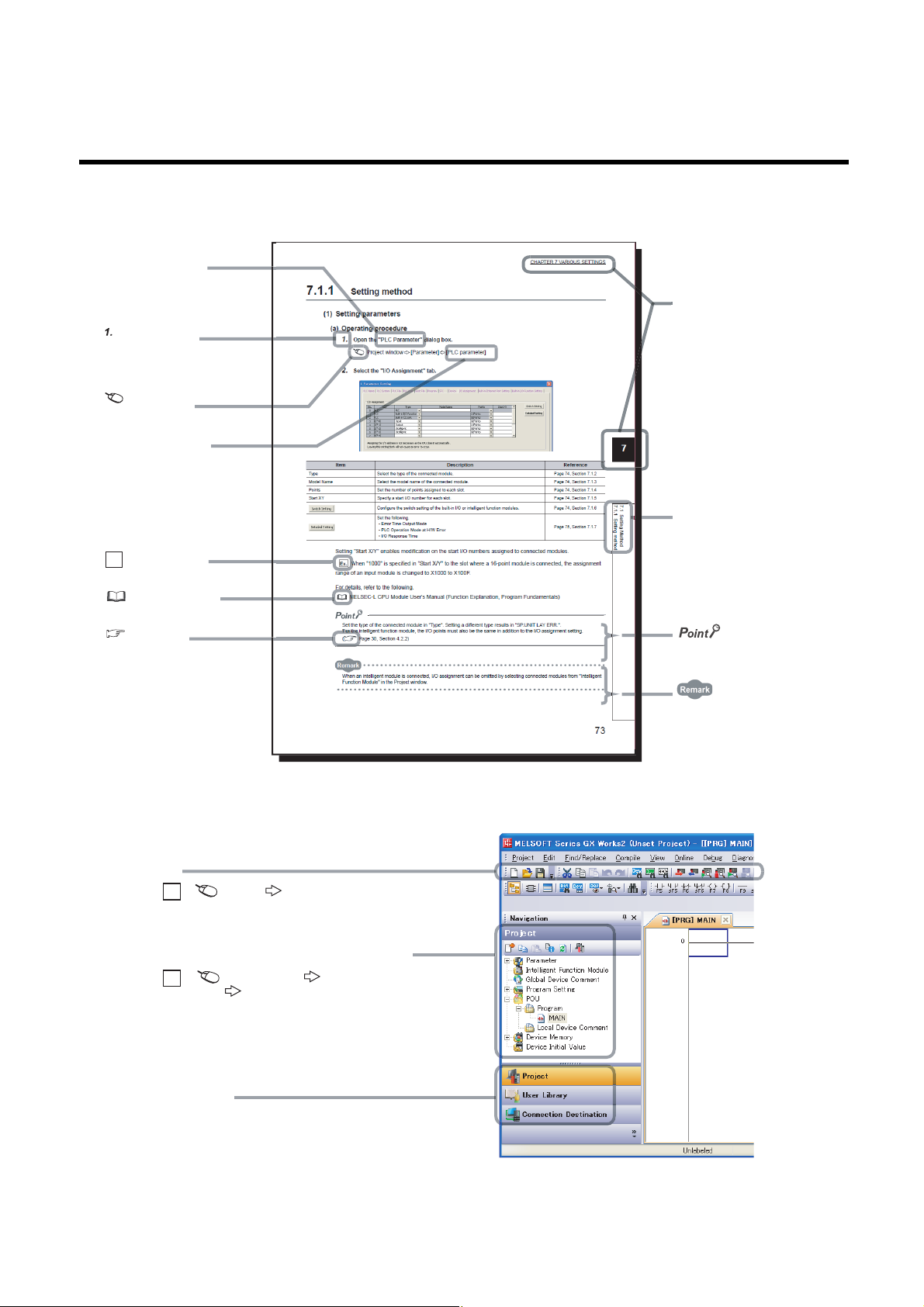
MANUAL PAGE ORGANIZATION
The section of
the current page is shown.
The chapter of
the current page is shown.
"" is used for window
names and items.
[ ] is used for items
in the menu bar and
the project window.
shows operating
procedures.
shows reference
manuals.
shows notes that
requires attention.
shows mouse
operations.
*1
shows
reference pages.
shows setting or
operating examples.
Ex.
shows useful
information.
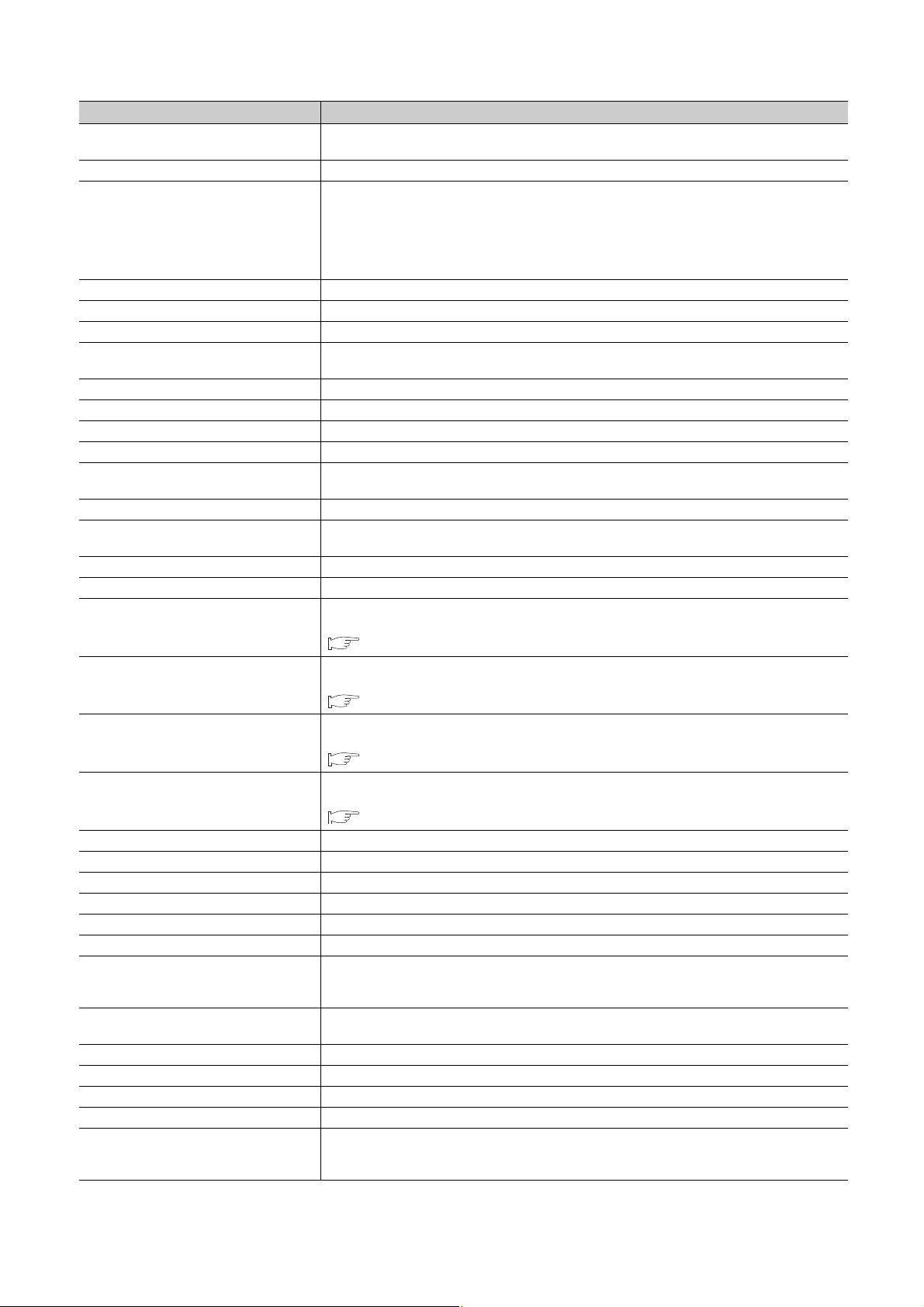
A window selected in the view selection area is displayed.
View selection area
[Online] [Write to PLC...]
Select [Online] on the menu bar,
and then select [Write to PLC...].
Project window
[Parameter]
[PLC Parameter]
Select [Project] from the view selection
area to open the Project window.
Menu bar
Ex.
Ex.
In the Project window, expand [Parameter] and
select [PLC Parameter].
In this manual, pages are organized and the symbols are used as shown below.
The following illustration is for explanation purpose only, and should not be referred to as an actual documentation.
*1 The mouse operation example is provided below.
15

TERM
Unless otherwise specified, this manual uses the following terms.
Ter m Description
ACPU Another term for the MELSEC-A series CPU module
Baton pass A token to send data over a network
Buffer memory
Buffer memory address
CC-Link
CC-Link dedicated instruction
CC-Link IE Field Network A high-speed and large-capacity open field network that is based on Ethernet (1000BASE-T)
CC-Link IE Field Network interface board The abbreviation for the Q81BD-J71GF11-T2 CC-Link IE Field Network interface board
CCPASET The abbreviation for GP.CCPASET
Control CPU
Control system CPU A CPU module that controls operations in a redundant system
Cyclic transmission
Data link Generic term for cyclic transmission and transient transmission
Dedicated instruction An instruction that simplifies programming for using functions of intelligent function modules
Device A device (X, Y, M, D, or others) in a CPU module
Disconnection A process of stopping data link if a data link error occurs
Ethernet adapter module The abbreviation for the NZ2GF-ETB CC-Link IE Field Network Ethernet adapter module
Ethernet device A generic term for devices, such as personal computers, that support IP (Internet Protocol) communications
GX Works2 The product name of the software package for the MELSEC programmable controllers
Head module The abbreviation for the LJ72GF15-T2 CC-Link IE Field Network head module
Intelligent device station
Intelligent function module
LCPU Another term for the MELSEC-L series CPU module
Link dedicated instruction
Link device A device (RX, RY, RWr, or RWw) in a module on CC-Link IE Field Network
Link refresh
Link scan (Link scan time)
Link special register (SW) Word data that indicates the operating status and data link status of a module on CC-Link IE Field Network
Link special relay (SB) Bit data that indicates the operating status and data link status of a module on CC-Link IE Field Network
Local station
Loopback
Master operating station
A memory in an intelligent function module, where data (such as setting values and monitoring values)
exchanged with a CPU module are stored
An address that indicates the storage location of data assigned to the buffer memory in an intelligent
function module
A field network system where data processing for control and information can be simultaneously performed
at high speed.
A dedicated instruction used for transient transmission with a CC-Link IE Field Network device. This
instruction allows a master/local module to communicate with the device on the same network.
A CPU module that controls connected I/O modules and intelligent function modules. In a multiple CPU
system, there are multiple CPU modules and each connected module can be controlled by a different CPU
module.
A function by which data are periodically exchanged among stations on the same network using link devices
(RX, RY, RWw, and RWr)
A station that exchanges I/O signals (bit data) and I/O data (word data) with another station by cyclic
transmission. This station responds to a transient transmission request from another station and also issues
a transient transmission request to another station.
A MELSEC-Q, -L, or iQ-R series module that has functions other than input and output, such as an A/D
converter module and D/A converter module
A dedicated instruction used for transient transmission with a programmable controller on another station.
This instruction allows a master/local module to communicate with programmable controllers on the same
network (CC-Link IE Field Network) and on other networks (Ethernet, CC-Link IE Controller Network, and
MELSECNET/H).
Data transfer between a link device in a module on CC-Link IE Field Network and a device in a CPU
module. Link refresh is performed in the END processing of the CPU module's sequence scan.
Time required for all the stations on the network to transmit data. The link scan time depends on data
volume and the number of transient transmission requests.
A station that performs cyclic transmission and transient transmission with the master station and other local
stations.
A function that disconnects the station in which an error has occurred, and continues data link with the
stations that are operating normally. Stations connected after the faulty station can also continue data link.
A station that controls the entire system in the network where a master station and submaster station are
connected. The connected master station or submaster station works as a master operating station.
16
Term Description
Master station
Master/local module The abbreviation for the QJ71GF11-T2 CC-Link IE Field Network master/local module
Network module
QCPU Another term for the MELSEC-Q series CPU module
QnACPU Another term for the MELSEC-QnA series CPU module
QSCPU Another term for the MELSEC-QS series CPU module
RAS
RCPU Another term for the MELSEC iQ-R series CPU module
READ The abbreviation for JP.READ and GP.READ
RECV The abbreviation for JP.RECV and GP.RECV
RECVS The abbreviation for Z.RECVS
Relay station
REMFR The abbreviation for ZP.REMFR
Remote device station
Remote head module The abbreviation for the RJ72GF15-T2 CC-Link IE Field Network remote head module
Remote I/O station A station that exchanges I/O signals (bit data) with the master station by cyclic transmission
Remote input (RX)
Remote output (RY)
Remote register (RWr)
Remote register (RWw)
REMTO The abbreviation for ZP.REMTO
REQ The abbreviation for JP.REQ and GP.REQ
Reserved station A station reserved for future use. This station is not actually connected, but counted as a connected station.
Return Process of restarting data link when a station recovers from an error
RIRD The abbreviation for JP.RIRD and GP.RIRD
RIWT The abbreviation for JP.RIWT and GP.RIWT
Routing
Seamless communications
SEND The abbreviation for JP.SEND and GP.SEND
Slave station A generic term for a local station, remote I/O station, remote device station, and intelligent device station
SREAD The abbreviation for JP.SREAD and GP.SREAD
Standby system CPU A CPU module that stands by in case the control system fails in a redundant system
Submaster operating station
A station that controls the entire network. This station can perform cyclic transmission and transient
transmission with all stations. Only one master station can be used in a network.
A generic term for the following modules:
• CC-Link IE Field Network module
• CC-Link IE Controller Network module
• Ethernet interface module
• MELSECNET/H module
• MELSECNET/10 module
The abbreviation for Reliability, Availability, and Serviceability. This term refers to usability of automated
equipment.
A station that includes two or more network modules. Data are passed through this station to stations on
other networks.
A station that exchanges I/O signals (bit data) and I/O data (word data) with another station by cyclic
transmission. This station responds to a transient transmission request from another station.
Bit data input from a slave station to the master station (For some areas in a local station, data are input in
the opposite direction.)
Page 124, Section 8.1.1
Bit data output from the master station to a slave station (For some areas in a local station, data are output
in the opposite direction.)
Page 124, Section 8.1.1
Word data input from a slave station to the master station (For some areas in a local station, data are input
in the opposite direction.)
Page 124, Section 8.1.1
Word data output from the master station to a slave station (For some areas in a local station, data are
output in the opposite direction.)
Page 124, Section 8.1.1
A process of selecting paths for communication with other networks.
CC-Link IE Field Network requires communication paths to be preset using routing parameters to
communicate with stations on different networks.
Communication that allows users to access a different kind of networks without having to consider the
differences as if data were exchanged within one single network
A station that monitors the status of a master operating station in the network where a master station and
submaster station are connected. The connected master station or submaster station works as a submaster
operating station.
17

Ter m Description
Submaster station
SWRITE The abbreviation for JP.SWRITE and GP.SWRITE
System A CPU A CPU module where the system A connector of a tracking cable is connected in a redundant system
System B CPU A CPU module where the system B connector of a tracking cable is connected in a redundant system
Transient transmission
UINI The abbreviation for Z.UINI and ZP.UINI
WRITE The abbreviation for JP.WRITE and GP.WRITE
A station that serves as a master station to control the entire network if the master station is disconnected.
Only one submaster station can be used in a network.
A function of communication with another station, which is used when requested by a dedicated instruction
or GX Works2
18
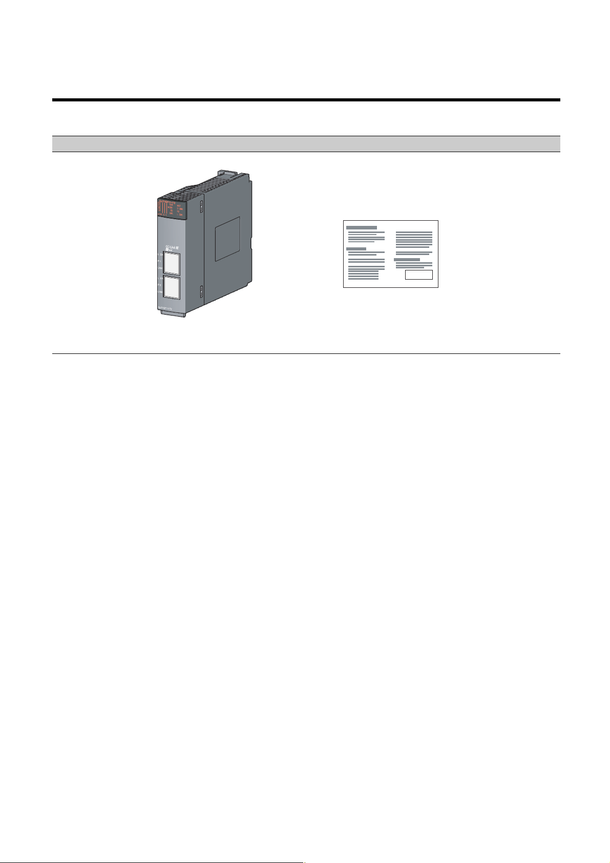
PACKING LIST
QJ71GF11-T2 Before Using the Product
The following items are included in the package of this product. Before use, check that all the items are included.
QJ71GF11-T2
19
CHAPTER 1 CC-LINK IE FIELD NETWORK
Master
station
CPU module
X
Y
W
RX
RY
RWw
RWr
Local station
CPU module
Y
X
W
RY
RX
RWr
RWw
RX
RY
RWw
RWr
RX
RY
RWw
RWr
Intelligent
device station
Intelligent
device station
Master station Local stationIntelligent
device station
Intelligent
device station
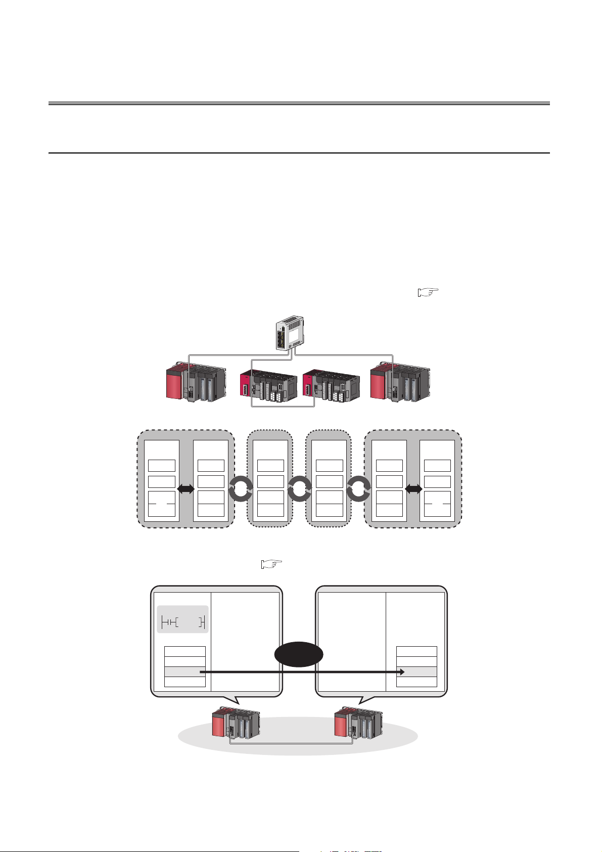
1.1 CC-Link IE Field Network
CC-Link IE Field Network is a high-speed and large-capacity open field network that is based on Ethernet technology
(1000BASE-T).
(1) Data communication
High-speed and large-capacity data communication is available between a master station and slave stations on
CC-Link IE Field Network.
(a) Periodic communication (cyclic transmission)
Data is periodically communicated among stations within the same network. ( Page 123, Section 8.1)
20
(b) Irregular communications (transient transmission)
Data is communicated upon request. ( Page 144, Section 8.2)
Master station Local station
Write
request
H
Intelligent
device station
CPU module CPU module
Command
Instruction
Device
1234
Device
1234
H
CHAPTER 1 CC-LINK IE FIELD NETWORK
1000BASE-T
(2) 1Gbps communication speed
1Gbps communication speed allows high-speed communication. Also, the takt time can be reduced due to the
improved performance of communication response.
(3) Use of Ethernet cable
A 1000BASE-T-compliant Ethernet is used for the connection interface. The wiring cost can be reduced because
1000BASE-T-compliant Ethernet cables are commercially available. ( Page 59, Section 5.3)
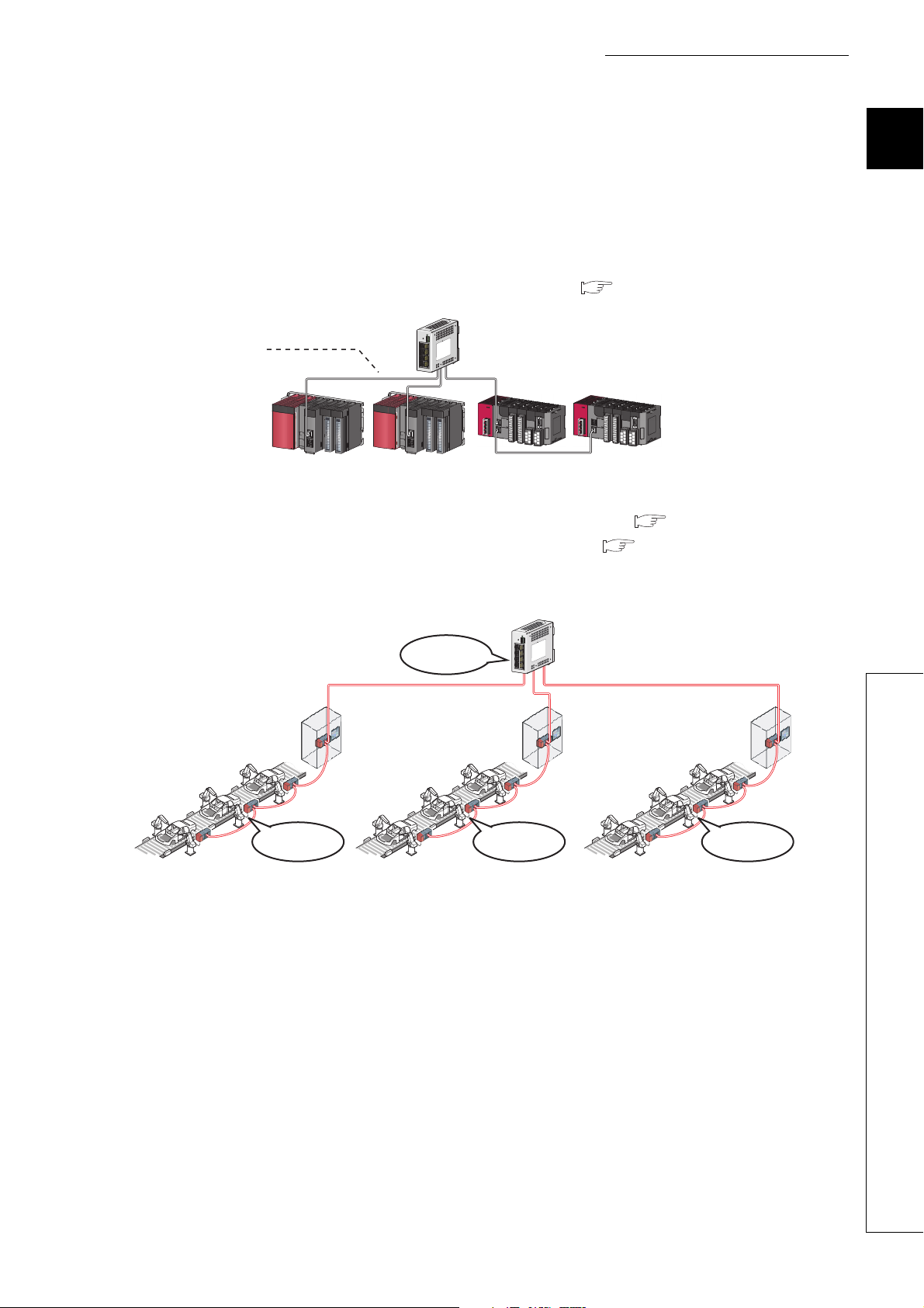
(4) Flexible wiring for system arrangements
The network can be wired into star topology, line topology, and ring topology. ( Page 49, Section 5.2.1)
For star topology, a 1000BASE-T compliant switching hub can be used. ( Page 60, Section 5.3.2)
Wiring is highly flexible because a network can consist of a combination of star and line topologies. For example,
the control panels can be connected through a star topology and the production lines through a line topology.
1
Star topology
Line topology Line topology Line topology
1.1 CC-Link IE Field Network
21
1.2 Master/Local Modules
A master/local module is used to connect a MELSEC-Q series programmable controller to CC-Link IE Field Network.
The module works as a master station or a local station on CC-Link IE Field Network.
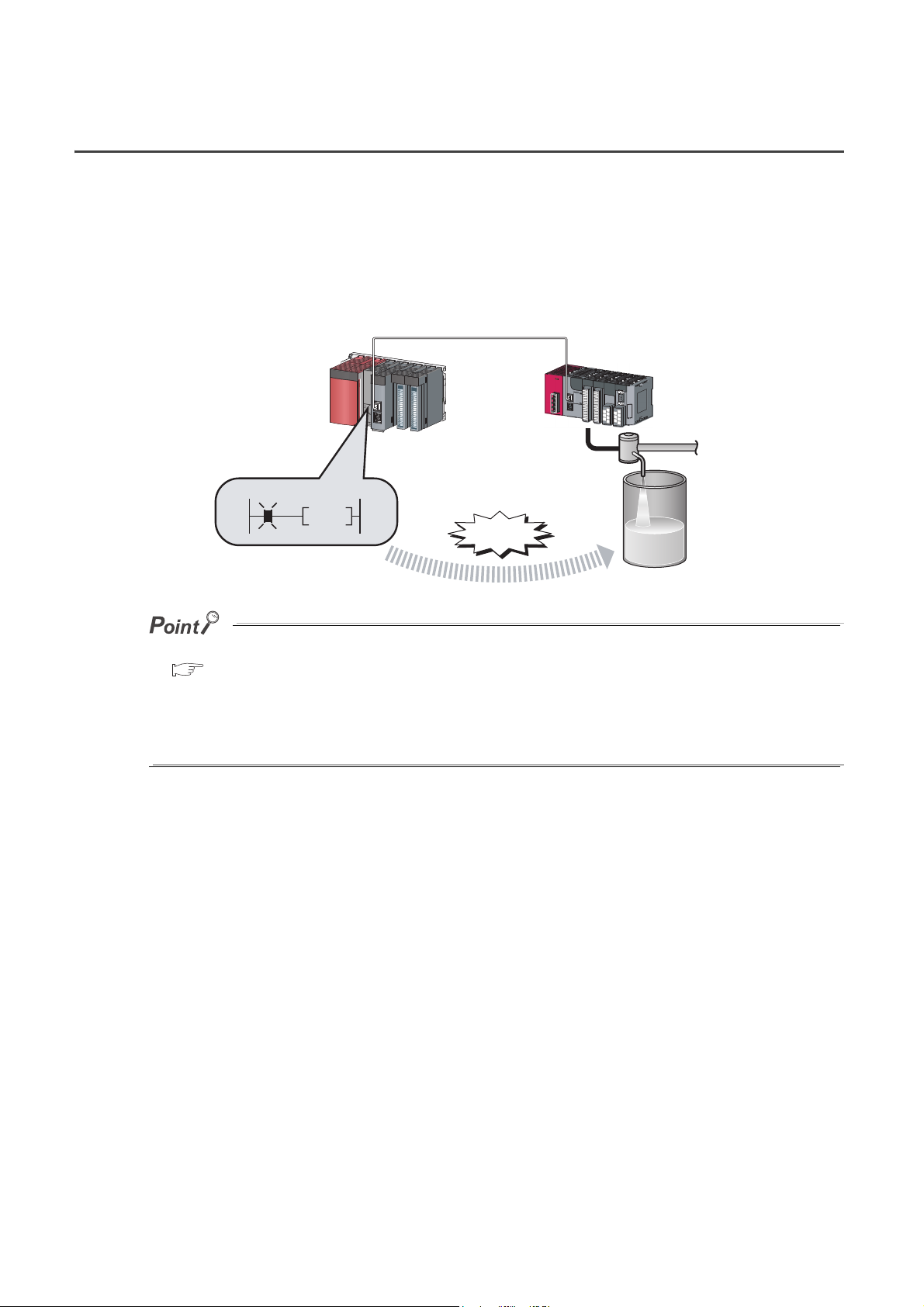
(1) High-speed periodic communication (cyclic transmission)
Since transmission delay time is short, delay caused during communication does not need to be considered (if the
link scan time of each master/local module is shorter than the scan time of the CPU module).
Command
High speed
Master/local modules can perform cyclic transmissions in combination with the following functions:
( Page 36, Section 3.3)
• Auto transfer of data between the link devices in the master/local module and the devices in the CPU module
• Direct access to the link devices in the master/local module by a program
• Cyclic data assurance in units of 32 bits or per station
• Status setting (hold or clear) of input data from a slave station where a cyclic error has occurred
• Station reservation for future connection, and others
22

CHAPTER 1 CC-LINK IE FIELD NETWORK
Command
READ
Device Device
1234
H
1234
H
CPU module CPU module
Master station Local station
(2) Irregular communications with the programmable controller on another station
(transient transmission)
(a) Reading or writing data
A master/local module can access programmable controllers on other stations by dedicated instructions.
( Page 236, Section 10.1)
Seamless access of programmable controllers on other networks such as Ethernet, CC-Link IE Controller
Network, MELSECNET/H, and MELSECNET/10 is also possible.
1
1.2 Master/Local Modules
23
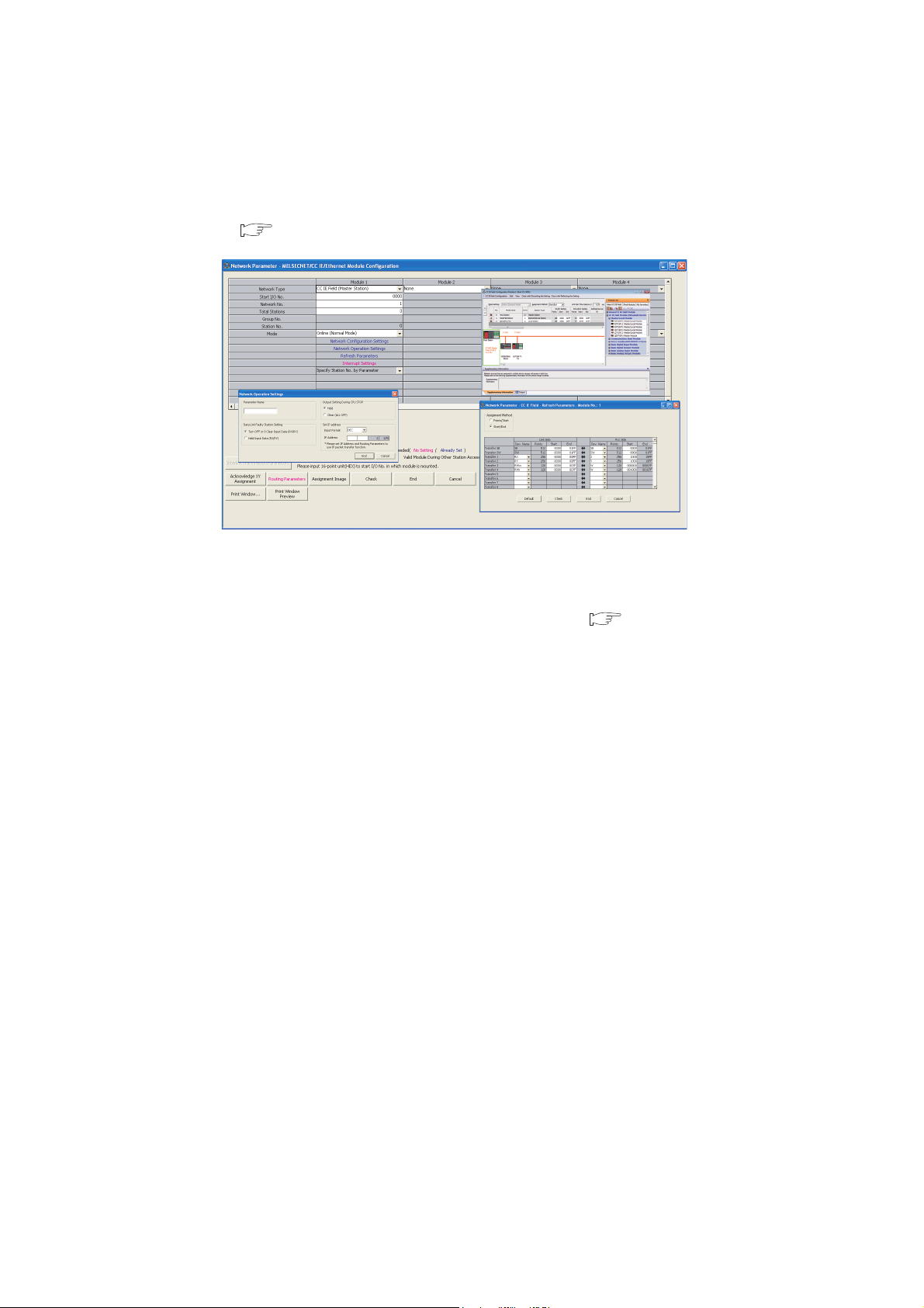
(3) Settings and diagnostics by GX Works2
(a) Setting parameters
Parameters for master/local modules can be set using GX Works2. Creating parameter setting programs is not
necessary. ( Page 81, CHAPTER 7)
Parameters for master/local modules can be also set by a program. ( Page 359, Section 10.17)
When set by a program, the parameters of the master station can be changed while the CPU module is
running.
24
CHAPTER 1 CC-LINK IE FIELD NETWORK
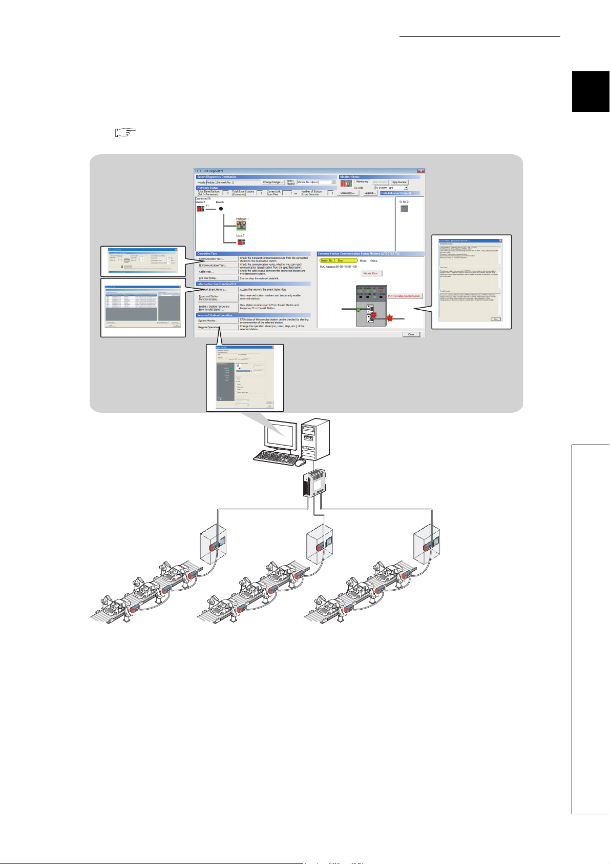
(b) Checking CC-Link IE Field Network status graphically
The CC-Link IE Field Network status can be checked using GX Works2. Error locations, error causes, and
event history are displayed on the window. This allows the system to quickly recover from errors.
( Page 206, CHAPTER 9)
1
1.2 Master/Local Modules
25
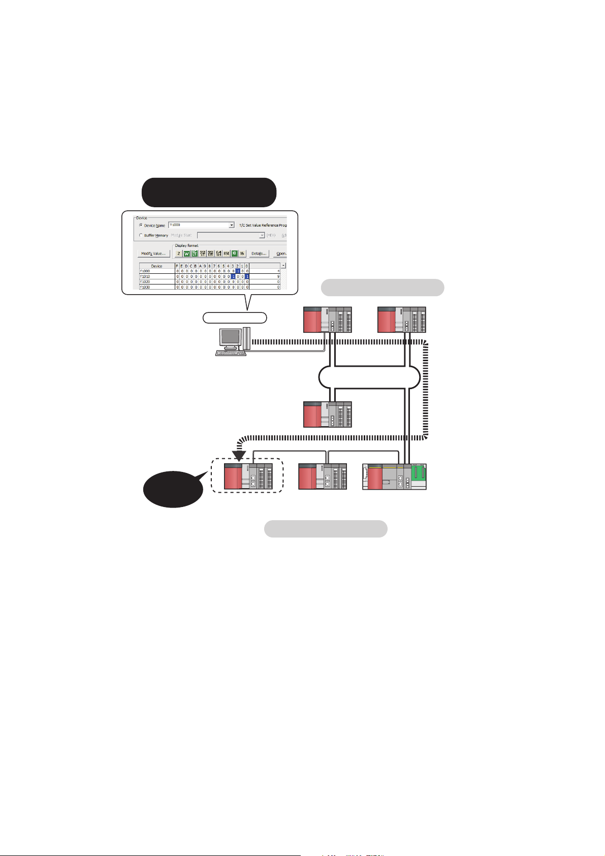
(c) Seamless access to other networks
GX Works2
CC-Link IE field network
CC-Link IE controller network
Network No.2
Network No.1
(Relay station)
Seamless
access
Systems on other networks
can be tested or monitored.
GX Works2 can seamlessly access (test or monitor) systems composed of other networks through CC-Link IE
Field Network. The accessible networks are Ethernet, CC-Link IE Controller Network, MELSECNET/H,
MELSECNET/10, and CC-Link.
Seamless access enables the user to change the access target without modifying the connection between the
personal computer and programmable controller.
26
CHAPTER 1 CC-LINK IE FIELD NETWORK
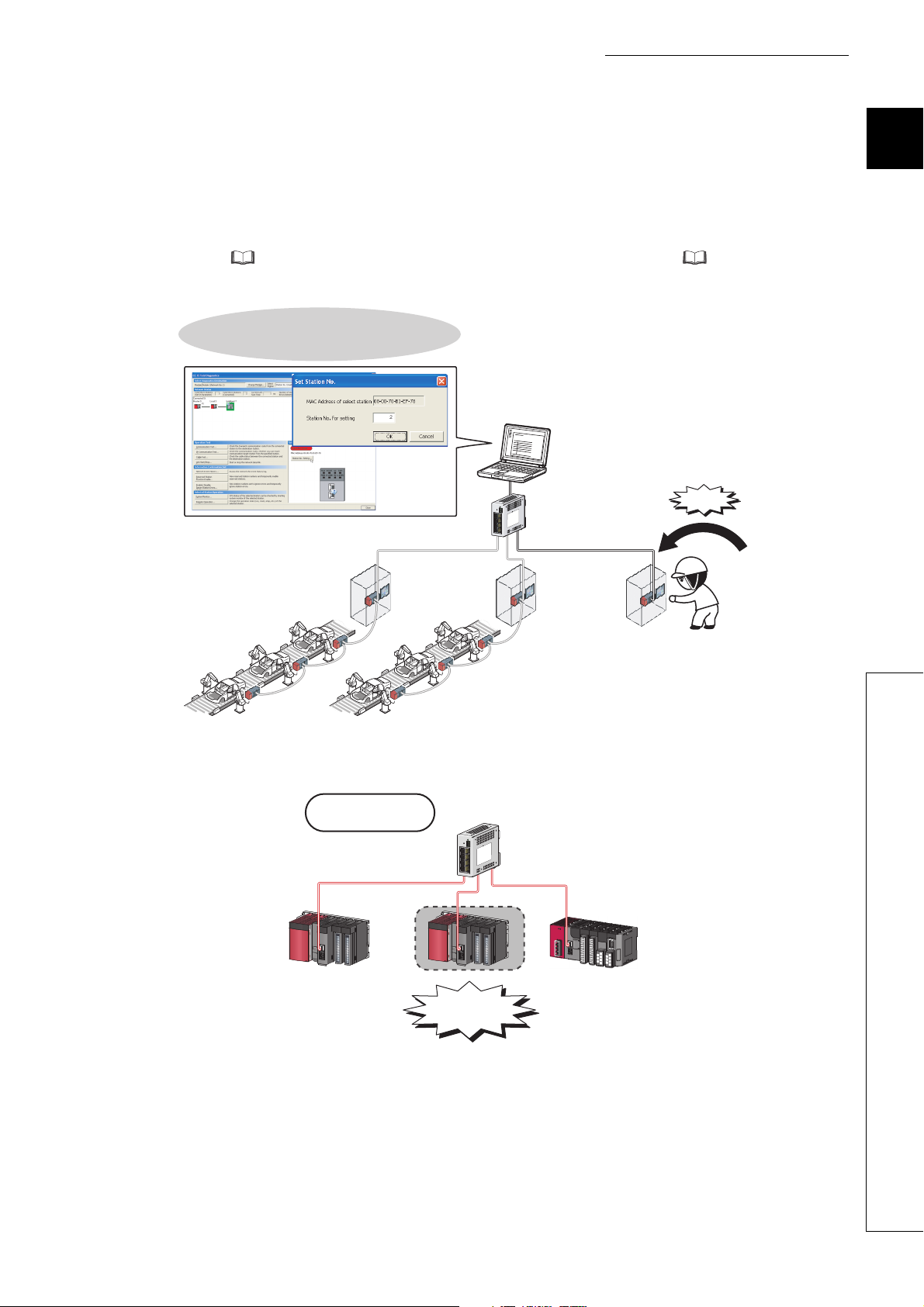
Connection of an added module can be
recognized, and setting a station No. on the
screen allows tentative operation.
Addition
Replacement
Star topology
(4) Adding and replacing CC-Link IE Field Network devices without stopping the
system
(a) Adding CC-Link IE Field Network devices
CC-Link IE Field Network devices whose parameters have not been set can be added without powering off the
system. ( MELSEC-L CC-Link IE Field Network Head Module User's Manual, MELSEC iQ-R CC-
Link IE Field Network Remote Head Module User's Manual (Application))
1
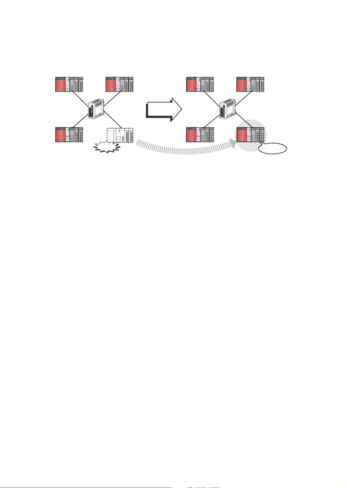
(b) Replacing CC-Link IE Field Network devices
For star topology, slave stations can be replaced without powering off the whole system.
1.2 Master/Local Modules
27
(c) Automatic return when disconnected stations recover
When
recovered
from fault
Master station
Station No.0
Slave station
Station No.1
Slave station
Station No.3
Slave station
Station No.2
Return
Down
Master station
Station No.0
Slave station
Station No.1
Slave station
Station No.3
Slave station
Station No.2
When the station disconnected from the network due to a data link error recovers, it automatically returns to the
network and restarts data link.
28
 Loading...