


MELSEC-Q EtherNet/IP Network Interface Module
User's Manual
-QJ71EIP71
-SW1DNC-EIPUTL-E

SAFETY PRECAUTIONS
WARNING
CAUTION
Indicates that incorrect handling may cause hazardous conditions,
resulting in death or severe injury.
Indicates that incorrect handling may cause hazardous conditions,
resulting in minor or moderate injury or property damage.
(Read these precautions before using this product.)
Before using this product, please read this manual and the relevant manuals carefully and pay full attention
to safety to handle the product correctly.
In this manual, the safety precautions are classified into two levels: " WARNING" and " CAUTION".
Under some circumstances, failure to observe the precautions given under " CAUTION" may lead to
serious consequences.
Observe the precautions of both levels because they are important for personal and system safety.
Make sure that the end users read this manual and then keep the manual in a safe place for future
reference.
[Design Precautions]
WARNING
● When connecting a peripheral with the programmable controller CPU or connecting a personal
computer with an intelligent function module to modify data of a running programmable controller,
configure an interlock circuit in the sequence program to ensure that the entire system will always
operate safely.
For other forms of control (such as program modification or operating status change) of a running
programmable controller, read the relevant manuals carefully and ensure that the operation is safe
before proceeding.
Especially, when a remote programmable controller is controlled by an external device, immediate
action cannot be taken if a problem occurs in the programmable controller due to a communication
failure. To prevent this, configure an interlock circuit in the program, and determine corrective actions
to be taken between the external device and CPU module in case of a communication failure.
● Do not write any data to the "system area" in the buffer memory of the intelligent function module.
Also, do not use any "use prohibited" signal as an output signal from the CPU module to the
intelligent function module.
Doing these operations may cause malfunctions to the programmable controller system.
● Provide security measures on user side that prevent unauthorized access from outside via network
as necessary.
A - 1

[Installation Precautions]
CAUTION
● Use the programmable controller in an environment that meets the general specifications in the
user's manual for the CPU module used.
Failure to do so may result in electric shock, fire, malfunction, or damage to or deterioration of the
product.
● To mount the module, while pressing the module mounting lever located in the lower part of the
module, fully insert the module fixing projection(s) into the hole(s) in the base unit and press the
module until it snaps into place.
Incorrect mounting may cause malfunction, failure or drop of the module.
When using the programmable controller in an environment of frequent vibrations, fix the module
with a screw.
Tighten the screws within the specified torque range.
Undertightening can cause drop of the screw, short circuit, or malfunction.
Overtightening can damage the screw and/or module, resulting in drop, short circuit, or malfunction.
● Shut off the external power supply (all phases) used in the system before mounting or removing the
module.
Failure to do so may result in damage to the product.
● Do not directly touch any conductive parts and electronic components of the module.
Doing so can cause malfunction or failure of the module.
A - 2

[Wiring Precautions]
WARNING
● Shut off the external power supply (all phases) used in the system before wiring.
Failure to do so may result in electric shock or damage to the product.
● Connectors for external devices must be crimped or pressed with the tool specified by the
manufacturer, or must be correctly soldered.
Incomplete connections may cause short circuit, fire, or malfunction.
CAUTION
● Securely connect the connector to the module.
● Place the communication cable or power cable in a duct or clamp it.
If not, dangling cable may swing or inadvertently be pulled, resulting in damage to the module or
cables or malfunction due to poor contact.
● Check the type of the interface to be connected before wiring the modules.
Connecting to a wrong interface or incorrect wiring may cause a fire or failure.
● When disconnecting a communication cable or power cable from the module, do not pull the cable
part.
For the cable with connector, hold the connector part of the cable.
Pulling the cable connected to the module may result in malfunction or damage to the module or
cable.
● Prevent foreign matter such as dust or wire chips from entering the module.
Such foreign matter can cause a fire, failure, or malfunction.
● A protective film is attached to the top of the module to prevent foreign matter, such as wire chips,
from entering the module during wiring.
Do not remove the film during wiring.
Remove it for heat dissipation before system operation.
● Do not install the control lines or communication cables together with the main circuit lines or power
cables.
Keep a distance of 100mm or more between them.
Failure to do so may result in malfunction due to noise.
A - 3
[Startup and Maintenance Precautions]
WARNING
● Do not touch any terminal while power is on.
Doing so will cause electric shock or malfunction.
● Shut off the external power supply (all phases) used in the system before cleaning the module or
retightening the module fixing screws.
Failure to do so may result in electric shock or cause the module to fail or malfunction.
Undertightening can cause drop of the screw, short circuit, or malfunction.
Overtightening can damage the screw and/or module, resulting in drop, short circuit, or malfunction.
CAUTION
● Before performing online operations (especially, program modification, forced output, and operation
status change) for the running CPU module from the peripheral connected, read relevant manuals
carefully and ensure the safety.
Improper operations may damage machines or cause accidents.
● Do not disassemble or modify the modules.
Doing so may cause failure, malfunction, injury, or a fire.
● Use any radio communication device such as a cellular phone or PHS (Personal Handy-phone
System) more than 25cm (9.85 inches) away in all directions from the programmable controller.
Failure to do so may cause malfunction.
● Shut off the external power supply (all phases) used in the system before mounting or removing the
module.
Failure to do so may cause the module to fail or malfunction.
● After the first use of the product, do not mount/remove the module to/from the base unit more than
50 times (IEC 61131-2 compliant).
Exceeding the limit of 50 times may cause malfunction.
● Do not drop or apply shock to the battery to be installed in the module.
Doing so may damage the battery, causing the battery fluid to leak inside the battery.
If the battery is dropped or any shock is applied to it, dispose of it without using.
● Before handling the module, touch a conducting object such as a grounded metal to discharge the
static electricity from the human body.
Failure to do so may cause the module to fail or malfunction.
A - 4
[Startup and Maintenance Precautions]
WARNING
● Before performing online operations (especially, program modification, forced output, and operation
status change) for the running CPU module from the peripheral connected, read relevant manuals
carefully and ensure the safety.
Incorrect change or modification may cause system malfunction, damage to the machines, or
accidents.
● Do not write any data to the "system area" in the buffer memory of the intelligent function module.
Also, do not use any "use prohibited" signal as an output signal from the CPU module to the
intelligent function module.
Doing these operations may cause malfunctions to the programmable controller system.
[Disposal Precautions]
CAUTION
● When disposing of this product, treat it as industrial waste.
When disposing of batteries, separate them from other wastes according to the local regulations.
(For the Battery Directive in EU member states, refer to Appendix 2.)
[Transportation Precautions]
CAUTION
● When transporting lithium batteries, follow the transportation regulations. (For details of the
regulated models, refer to Appendix 1.)
A - 5

CONDITIONS OF USE FOR THE PRODUCT
(1) Mitsubishi programmable controller ("the PRODUCT") shall be used in conditions;
i) where any problem, fault or failure occurring in the PRODUCT, if any, shall not lead to any major
or serious accident; and
ii) where the backup and fail-safe function are systematically or automatically provided outside of
the PRODUCT for the case of any problem, fault or failure occurring in the PRODUCT.
(2) The PRODUCT has been designed and manufactured for the purpose of being used in general
industries.
MITSUBISHI SHALL HAVE NO RESPONSIBILITY OR LIABILITY (INCLUDING, BUT NOT
LIMITED TO ANY AND ALL RESPONSIBILITY OR LIABILITY BASED ON CONTRACT,
WARRANTY, TORT, PRODUCT LIABILITY) FOR ANY INJURY OR DEATH TO PERSONS OR
LOSS OR DAMAGE TO PROPERTY CAUSED BY the PRODUCT THAT ARE OPERATED OR
USED IN APPLICATION NOT INTENDED OR EXCLUDED BY INSTRUCTIONS, PRECAUTIONS,
OR WARNING CONTAINED IN MITSUBISHI'S USER, INSTRUCTION AND/OR SAFETY
MANUALS, TECHNICAL BULLETINS AND GUIDELINES FOR the PRODUCT.
("Prohibited Application")
Prohibited Applications include, but not limited to, the use of the PRODUCT in;
• Nuclear Power Plants and any other power plants operated by Power companies, and/or any
other cases in which the public could be affected if any problem or fault occurs in the PRODUCT.
• Railway companies or Public service purposes, and/or any other cases in which establishment of
a special quality assurance system is required by the Purchaser or End User.
• Aircraft or Aerospace, Medical applications, Train equipment, transport equipment such as
Elevator and Escalator, Incineration and Fuel devices, Vehicles, Manned transportation,
Equipment for Recreation and Amusement, and Safety devices, handling of Nuclear or
Hazardous Materials or Chemicals, Mining and Drilling, and/or other applications where there is a
significant risk of injury to the public or property.
Notwithstanding the above, restrictions Mitsubishi may in its sole discretion, authorize use of the
PRODUCT in one or more of the Prohibited Applications, provided that the usage of the PRODUCT
is limited only for the specific applications agreed to by Mitsubishi and provided further that no
special quality assurance or fail-safe, redundant or other safety features which exceed the general
specifications of the PRODUCTs are required. For details, please contact the Mitsubishi
representative in your region.
A - 6

REVISIONS
*The manual number is given on the bottom left on the back cover.
Print date *Manual number Revision
July 2013 SH(NA)-081157ENG-A First edition
Added function
Setting of a tag name with 41 or more characters
February 2015 SH(NA)-081157ENG-B
Added or modified parts
GENERIC TERMS AND ABBREVIATIONS, Section 3.1, 3.3.1, 3.3.4, 3.3.5, 4.2,
5.2.1, 7.2.1, 7.2.2, 7.2.3, 7.6, 7.9.1, 7.9.2, 7.9.3, 7.9.4, 7.12, 8.3, 9.4.1, Appendix
5
Japanese Manual Version SH-081156-B
This manual confers no industrial property rights or any rights of any other kind, nor does it confer any patent licenses.
Mitsubishi Electric Corporation cannot be held responsible for any problem involving industrial property rights which may
occur as a result of using the contents noted in this manual.
© 2013 MITSUBISHI ELECTRIC CORPORATION
A - 7

INTRODUCTION
Thank you for purchasing the MELSEC-Q series programmable controller.
Before using the equipment, please read this manual carefully to develop full familiarity with the functions and
performance of the Q series programmable controller you have purchased, so as to ensure correct use.
Please forward a copy of this manual to the end user.
CONTENTS
SAFETY PRECAUTIONS ................................................................................................................................. A - 1
CONDITIONS OF USE FOR THE PRODUCT..................................................................................................A - 6
REVISIONS.......................................................................................................................................................A - 7
INTRODUCTION...............................................................................................................................................A - 8
CONTENTS ......................................................................................................................................................A - 8
COMPLIANCE WITH THE EMC AND LOW VOLTAGE DIRECTIVES...........................................................A - 12
HOW TO READ THIS MANUAL .....................................................................................................................A - 14
HOW TO USE THIS MANUAL ........................................................................................................................ A - 15
GENERIC TERMS AND ABBREVIATIONS....................................................................................................A - 16
DEFINITIONS OF TERMINOLOGY ................................................................................................................ A - 17
PACKING LIST ............................................................................................................................................... A - 18
CHAPTER 1 OVERVIEW 1 - 1 to 1 - 7
1.1 Features........................................................................................................................................... 1 - 2
CHAPTER 2 SYSTEM CONFIGURATION 2 - 1 to 2 - 9
2.1 Applicable Systems ......................................................................................................................... 2 - 1
2.2 Network Configuration and Components .........................................................................................2 - 4
2.2.1 Network configuration ............................................................................................................... 2 - 4
2.2.2 Network components of the EtherNet/IP network..................................................................... 2 - 5
2.3 Operating Environment for Utility Package ...................................................................................... 2 - 6
2.4 Checking the Function Version and Serial Number ......................................................................... 2 - 8
CHAPTER 3 SPECIFICATIONS 3 - 1 to 3 - 40
3.1 Performance Specifications ............................................................................................................. 3 - 1
3.2 I/O Signals for the QCPU................................................................................................................. 3 - 3
3.2.1 I/O signal list ............................................................................................................................. 3 - 3
3.2.2 Tag communication start request (Y00), Tag communication start process
completion (X00)....................................................................................................................... 3 - 4
3.2.3 PING test execution request (Y02), PING test completion (X02) ............................................. 3 - 8
3.2.4 Flash ROM access request (Y06)/Access completion (X06)/Access error
completion (X07)....................................................................................................................... 3 - 9
3.2.5 TCP/UDP/IP parameter change request (Y08), TCP/UDP/IP parameter change
completion (X08)..................................................................................................................... 3 - 10
A - 8

3.2.6 Acquiring IP address (X0D) .................................................................................................... 3 - 12
3.2.7 Own station error clear request (Y0E), Own station error (X0E) ............................................ 3 - 12
3.2.8 Module READY (X0F) ............................................................................................................ 3 - 14
3.2.9 Watch dog timer error (X1F) ................................................................................................... 3 - 14
3.3 Buffer Memory ............................................................................................................................... 3 - 15
3.3.1 Buffer memory list................................................................................................................... 3 - 15
3.3.2 Setting status.......................................................................................................................... 3 - 18
3.3.3 TCP/UDP/IP parameter ......................................................................................................... 3 - 19
3.3.4 Common parameter................................................................................................................ 3 - 20
3.3.5 Class1 Tag parameter ............................................................................................................ 3 - 20
3.3.6 Tag communication continue setting ...................................................................................... 3 - 21
3.3.7 Class1 send/receive data start address ................................................................................. 3 - 22
3.3.8 Class3/UCMM send/receive data start address ..................................................................... 3 - 23
3.3.9 Input Area ............................................................................................................................... 3 - 25
3.3.10 Output Area ............................................................................................................................ 3 - 27
3.3.11 Application Trigger (Class1) ................................................................................................... 3 - 29
3.3.12 Application Trigger (Class3/UCMM) ....................................................................................... 3 - 31
3.3.13 Operation status ..................................................................................................................... 3 - 34
3.3.14 Communication status (Class1).............................................................................................. 3 - 35
3.3.15 Communication status (Class3/UCMM) ................................................................................. 3 - 37
3.3.16 Own station error information ................................................................................................. 3 - 38
3.3.17 PING test ................................................................................................................................ 3 - 39
3.3.18 Checking the battery............................................................................................................... 3 - 40
CHAPTER 4 FUNCTION 4 - 1 to 4 - 25
4.1 Function List .................................................................................................................................... 4 - 1
4.2 Tag Communication Function .......................................................................................................... 4 - 2
4.2.1 Class1 Tag communication ...................................................................................................... 4 - 4
4.2.2 Class3 Tag communication .................................................................................................... 4 - 11
4.2.3 UCMM Tag communication .................................................................................................... 4 - 17
4.3 Tag Communication Status Setting Function for CPU Stop Error ................................................. 4 - 22
4.4 Monitoring Function ....................................................................................................................... 4 - 23
4.5 DHCP Client Function.................................................................................................................... 4 - 24
CHAPTER 5 PRE-OPERATION PROCEDURES 5 - 1 to 5 - 24
5.1 Installation........................................................................................................................................ 5 - 1
5.1.1 Handling precautions ................................................................................................................ 5 - 1
5.2 Pre-Operation Procedures ............................................................................................................... 5 - 2
5.2.1 Consideration before configuring the EtherNet/IP network ...................................................... 5 - 2
5.2.2 Pre-operation procedures ......................................................................................................... 5 - 7
5.3 Part Names...................................................................................................................................... 5 - 9
5.4 Battery ........................................................................................................................................... 5 - 11
5.4.1 Battery specifications.............................................................................................................. 5 - 11
5.4.2 Installing the battery ............................................................................................................... 5 - 11
5.4.3 Detecting a battery error and replacing the battery ................................................................ 5 - 12
A - 9

5.5 Setting from GX Works2 ................................................................................................................ 5 - 15
5.5.1 Intelligent function module detailed setting ............................................................................. 5 - 15
5.5.2 Switch setting for the intelligent function module.................................................................... 5 - 16
5.6 Self-Diagnostics of the EtherNet/IP Module .................................................................................. 5 - 18
5.6.1 Hardware test ......................................................................................................................... 5 - 18
5.6.2 Self-loopback test ................................................................................................................... 5 - 20
5.7 Wiring............................................................................................................................................. 5 - 21
5.7.1 Wiring precautions .................................................................................................................. 5 - 22
5.8 PING Test ...................................................................................................................................... 5 - 23
CHAPTER 6 PARAMETER 6 - 1 to 6 - 2
6.1 Parameter List and Setting Method ................................................................................................. 6 - 1
6.2 Access to the Flash ROM ................................................................................................................ 6 - 2
CHAPTER 7 UTILITY PACKAGE (SW1DNC-EIPUTL-E) 7 - 1 to 7 - 68
7.1 Precautions ...................................................................................................................................... 7 - 2
7.2 Installing and Uninstalling ................................................................................................................ 7 - 4
7.2.1 Installing.................................................................................................................................... 7 - 4
7.2.2 Uninstalling ............................................................................................................................... 7 - 8
7.2.3 Installing USB driver ............................................................................................................... 7 - 10
7.3 Operating Procedure ..................................................................................................................... 7 - 16
7.4 Functions of Utility Package .......................................................................................................... 7 - 17
7.4.1 Function list of Utility Package................................................................................................ 7 - 17
7.5 Window Structure .......................................................................................................................... 7 - 18
7.5.1 Menus ..................................................................................................................................... 7 - 19
7.5.2 How to use the selection tree ................................................................................................. 7 - 20
7.6 "Main" Tab (Module Status Display) .............................................................................................. 7 - 21
7.7 Project File..................................................................................................................................... 7 - 24
7.7.1 Creating a new project............................................................................................................ 7 - 24
7.7.2 Opening a project ................................................................................................................... 7 - 25
7.7.3 Saving a project ...................................................................................................................... 7 - 26
7.8 Exporting Setting Data ................................................................................................................... 7 - 27
7.8.1 Exporting label data for GX Works2 ....................................................................................... 7 - 28
7.8.2 Exporting Tag Parameter........................................................................................................ 7 - 30
7.9 "Setting" Tab (Parameter Settings)................................................................................................ 7 - 31
7.9.1 "Basic" window ....................................................................................................................... 7 - 31
7.9.2 "Producer" window.................................................................................................................. 7 - 36
7.9.3 "Consumer" window................................................................................................................ 7 - 40
7.9.4 "Message" window.................................................................................................................. 7 - 44
7.9.5 "User Define" window ............................................................................................................. 7 - 48
7.9.6 "RPI Set" window.................................................................................................................... 7 - 50
7.9.7 "Refresh Parameter" window .................................................................................................. 7 - 51
7.10 Online ............................................................................................................................................ 7 - 54
7.10.1 Configuring the EtherNet/IP module ....................................................................................... 7 - 54
7.10.2 Writing parameters to the EtherNet/IP module ....................................................................... 7 - 56
A - 10

7.10.3 Reading out parameters of the EtherNet/IP module............................................................... 7 - 59
7.11 "Monitoring" tab (Network Diagnostics) ......................................................................................... 7 - 61
7.12 Help Menu ..................................................................................................................................... 7 - 68
CHAPTER 8 PROGRAMMING 8 - 1 to 8 - 18
8.1 System Configuration Example ....................................................................................................... 8 - 1
8.2 Setting Description for Communication ........................................................................................... 8 - 1
8.3 Parameter Setting............................................................................................................................ 8 - 3
8.4 Program Example .......................................................................................................................... 8 - 10
8.4.1 Program example of Tag communication ............................................................................... 8 - 12
CHAPTER 9 TROUBLESHOOTING 9 - 1 to 9 - 21
9.1 Troubleshooting Procedure ............................................................................................................. 9 - 1
9.2 Checking Errors by the LED and Corrective Actions ....................................................................... 9 - 2
9.3 When Tag Communication is Disabled............................................................................................ 9 - 3
9.3.1 When the ERR.LED is on or flashing ....................................................................................... 9 - 3
9.3.2 When the ERR.LED is off ......................................................................................................... 9 - 4
9.4 Error Code ....................................................................................................................................... 9 - 8
9.4.1 How to check error codes ......................................................................................................... 9 - 8
9.4.2 Error code list ......................................................................................................................... 9 - 10
APPENDICES APPX - 1 to APPX - 15
Appendix 1 Transportation Precautions ............................................................................................APPX- 1
Appendix 1.1 Controlled model ....................................................................................................APPX- 1
Appendix 1.2 Handling for transportation .....................................................................................APPX- 1
Appendix 2 Handling of Batteries and Devices with Built-in Batteries in EU Member States............ APPX- 2
Appendix 2.1 Disposal precautions ..............................................................................................APPX- 2
Appendix 2.2 Exportation precautions..........................................................................................APPX- 3
Appendix 3 When Using GX Developer ............................................................................................APPX- 4
Appendix 3.1 Operation of GX Developer ....................................................................................APPX- 4
Appendix 4 Calculation for the Total Size of Character String Information Parameters ....................APPX- 6
Appendix 4.1 Calculating formula for the total size of character string information parameters ..APPX- 6
Appendix 4.2 Example of the character string information parameter setting ..............................APPX- 7
Appendix 4.3 Examples of calculation for character string information parameters.....................APPX- 9
Appendix 5 Added and enhanced Functions ...................................................................................APPX- 14
Appendix 6 External Dimensions.....................................................................................................APPX- 14
INDEX INDEX - 1 to INDEX - 3
A - 11
COMPLIANCE WITH THE EMC AND LOW VOLTAGE DIRECTIVES
(1) For programmable controller system
To ensure that Mitsubishi programmable controllers maintain EMC and Low Voltage
Directives when incorporated into other machinery or equipment, certain measures
may be necessary. Please refer to one of the following manuals.
• QCPU User's Manual (Hardware Design, Maintenance and Inspection)
• Safety Guidelines
(This manual is included with the CPU module or base unit.)
The CE mark, indicating compliance with the EMC and Low Voltage Directives, is
printed on the rating plate of the programmable controller.
(2) For the product
For the compliance of this product with the EMC and Low Voltage Directives, refer to
the following precautions.
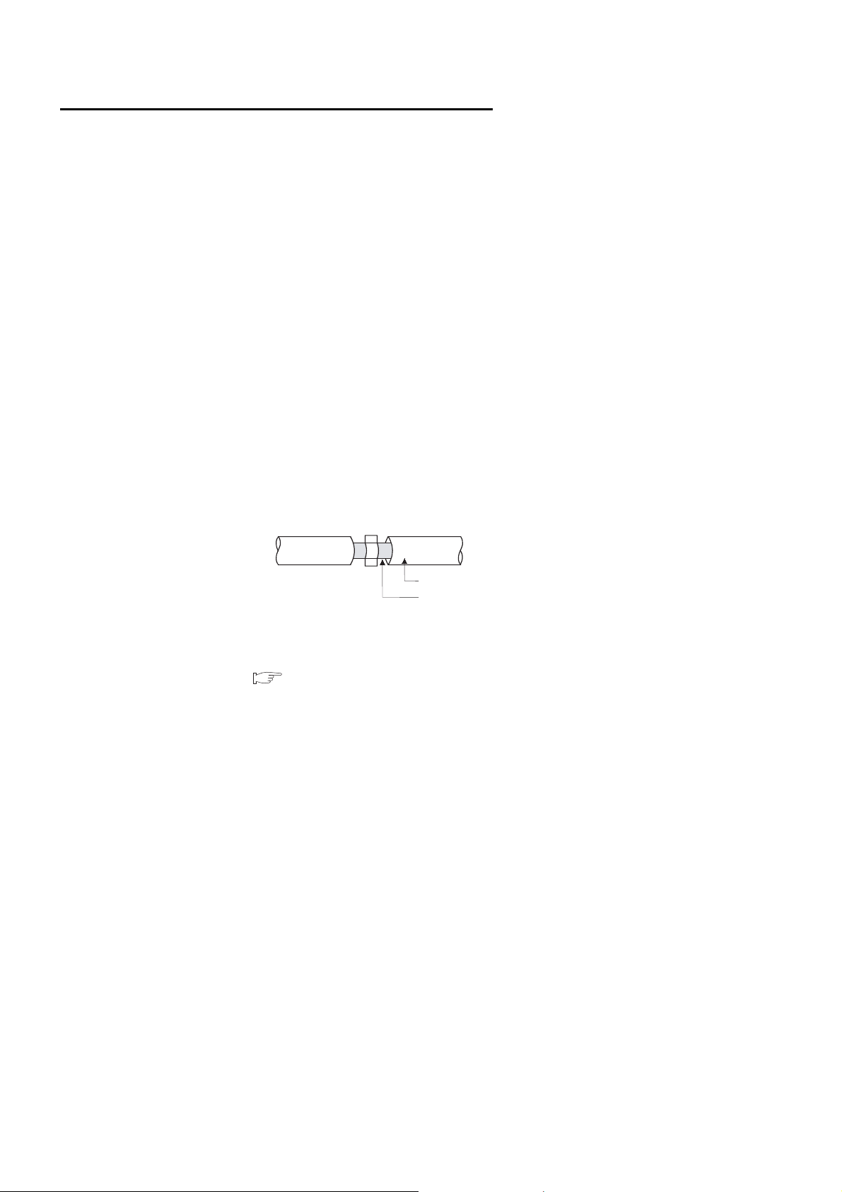
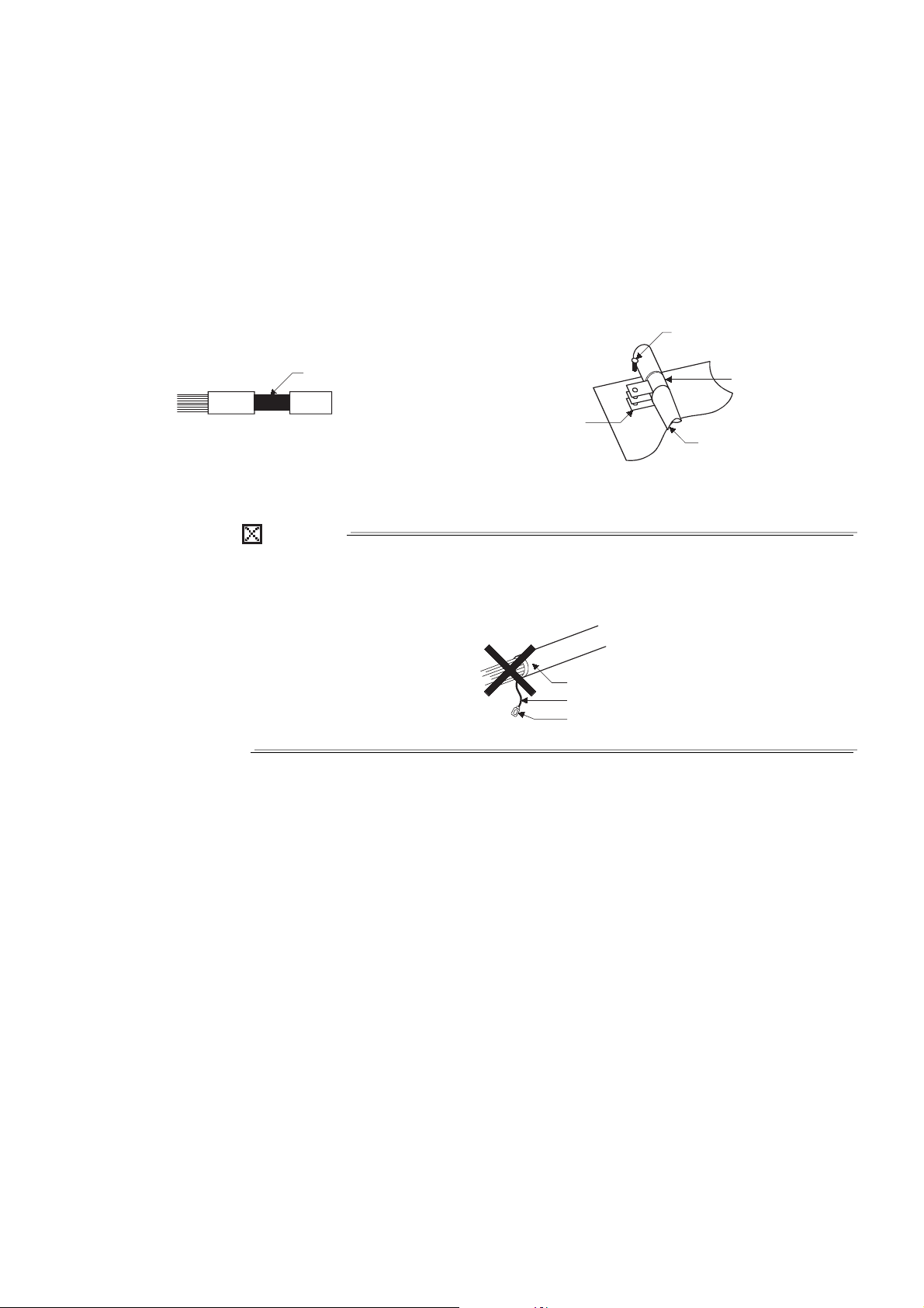
(a) Twisted pair cable
Always use shielded twisted pair cables for connection to 10BASE-T/100BASETX connectors.
For the shielded twisted pair cable, remove a part of the cable sheath as shown
below and ground the exposed shield section to the ground as much as possible.
Shielded twist pair cable
Shield
For grounding of the shield, refer to the following.
(2) (b) Grounding of the shield section of shielded cable in this section
A - 12
(b) Grounding of the shield section of shielded cable
POINT
Shield section
Screw
Clamp fitting
Shield cable
Masked
from paint
Shield cable
Wire
Solderless terminal
• Ground the exposed shield section of the shielded cable close to the module.
Confirm that the grounded cables are not induced to electromagnetic from
the cables, which are not yet grounded.
• Ground the exposed shield section to spacious area on the control panel.
A clamp can be used as shown below.
In this case, apply a cover on the painted inner wall surface of the control
panel, which comes in contact with the clamp.
Shield section to expose Grounding of the shield
The method of grounding with a vinyl-coated wire soldered onto the shield section
of the shielded cable is not recommended. High-frequency impedance will rise,
resulting in loss of shielding effect.
A - 13
HOW TO READ THIS MANUAL
Reference
A reference section or reference
manual is shown with .
Chapter heading
The index on the right side of the
page simply shows the chapter of the
open page.
Section title
The section number and title of the open
page is shown.
A - 14
This page is for reference only.

The following table shows the marks used in this manual.
Detail View
HOW TO USE THIS MANUAL
This manual describes the specifications, operating procedure, functions, and
troubleshooting of the QJ71EIP71 EtherNet/IP network interface module.
This manual consists of the following chapters. Refer to each chapter according to the
intended purpose.
CHAPTER 1 Explains the features of the EtherNet/IP network interface module.
CHAPTER 2
CHAPTER 3
CHAPTER 4 Explains the functions of the EtherNet/IP network interface module.
CHAPTER 5
CHAPTER 6 Explains the parameters of the EtherNet/IP network interface module.
CHAPTER 7
CHAPTER 8
CHAPTER 9 Explains the troubleshooting and error codes.
Mark Description
[ ]
" "
Item Description
Explains the system configuration and components for network configuration
with the EtherNet/IP network interface module.
Explains the specifications, I/O signals, and buffer memory of the EtherNet/IP
network interface module.
Explains the procedure for system operation using the EtherNet/IP network
interface module.
Explains the installation, functions, and operation of Utility Package
(SW1DNC-EIPUTL-E) for the EtherNet/IP network interface module.
Explains the examples of parameter setting and programming for the
EtherNet/IP network interface module.
Indicates menus shown in software.
Example: [Online] [Transfer Setup] menu
Indicates window titles and setting items shown in software.
Example: the "Basic" window
Indicates the buttons shown in software.
Example: button
A - 15

GENERIC TERMS AND ABBREVIATIONS
Unless otherwise specified, this manual describes the QJ71EIP71 EtherNet/IP network
interface module using the following items.
Generic term and
abbreviation
Ethernet A generic term for 100BASE-TX, 10BASE-T network systems
Built-in Ethernet port
QCPU
GX Developer
GX Works2 A generic product name for SWnDNC-GXW2 (n represents the version.)
QCPU
EtherNet/IP module The abbreviation for the QJ71EIP71 EtherNet/IP network interface module
Tag Parameter A generic term for Class1 Tag Parameter and Class3/UCMM Tag Parameter
Tag communication
Windows® 7
Windows Vista
Windows® XP The abbreviation for Microsoft® Windows® XP Professional Operating System
High Performance model
QCPU
Process CPU A generic term for the Q02PHCPU, Q06PHCPU, Q12PHCPU, Q25PHCPU
Basic model QCPU A generic term for the Q00JCPU, Q00CPU, Q01CPU
Utility Package A generic product name for SWnDNC-EIPUTL-E (n represents the version.)
Universal model QCPU
®
A generic term for the Q03UDVCPU, Q03UDECPU, Q04UDVCPU, Q04UDEHCPU,
Q06UDVCPU, Q06UDEHCPU, Q10UDEHCPU, Q13UDVCPU, Q13UDEHCPU,
Q20UDEHCPU, Q26UDVCPU, Q26UDEHCPU, Q50UDEHCPU, Q100UDEHCPU
A generic product name for SWnD5C-GPPW-E, SWnD5C-GPPW-EA, SWnD5C-GPPW-EV,
SWnD5C-GPPW-EVA. ("n" means version 4 or later.)
"-A "and "-V" mean "volume license product" and "version-upgrade product" respectively.
A generic term for the Basic model QCPU, High Performance model QCPU, Process CPU, and
Universal model QCPU
A generic term for Class1, Class3, and UCMM Tag communications ( DEFINITIONS OF
TERMINOLOGY)
A generic term for Microsoft® Windows® 7 Professional Operating System, Microsoft®
®
Windows
A generic term for Microsoft® Windows Vista® Business Operating System and Microsoft®
Windows Vista
A generic term for the Q02CPU, Q02HCPU, Q06HCPU, Q12HCPU, Q25HCPU
A generic term for the Q00UJCPU, Q00UCPU, Q01UCPU, Q02UCPU, Q03UDCPU,
Q03UDVCPU, Q03UDECPU, Q04UDHCPU, Q04UDVCPU, Q04UDEHCPU, Q06UDHCPU,
Q06UDVCPU, Q06UDEHCPU, Q10UDHCPU, Q10UDEHCPU, Q13UDHCPU, Q13UDVCPU,
Q13UDEHCPU, Q20UDHCPU, Q20UDEHCPU, Q26UDHCPU, Q26UDVCPU, Q26UDEHCPU,
Q50UDEHCPU, Q100UDEHCPU
7 Ultimate Operating System
®
Ultimate Operating System
Description
A - 16
DEFINITIONS OF TERMINOLOGY
Data flow
(Class1 Tag communication)
Producer Tag Consumer Tag
Originator
(Sending connection request)
Connection
Target
(Receiving connection request)
Definitions of the terms used in this manual are explained below.
Term Description
ACK
Application Trigger The trigger used to send/receive data at any given timing.
Class1 Tag communication
Class3 Tag communication
Consumer Tag
ACK (an abbreviation for Acknowledgement) is a message indicating successful data
reception, which is sent from receiving device (destination) back to the sending device (source).
A communication method by which cyclic data transmission is performed between Producer
(Producer Tag) and Consumer (Consumer Tag).
( Section 4.2.1 Class1 Tag communication)
A communication method using read or write request.
( Section 4.2.2 Class3 Tag communication)
Tag used for Class1 Tag communication ( Section 4.2.1 Class1 Tag communication)
Data are sent from Producer Tag to Consumer Tag.
DHCP (an abbreviation for Dynamic Host Configuration Protocol) is a protocol, which
DHCP
Ethernet address
(MAC address)
Originator
Producer Tag
RPI
automatically assigns parameters such as IP addresses to the devices connected to the
network.
A unique address used to distinguish the target device from another in a network.
MAC is an abbreviation for Media Access Control.
The Ethernet address (MAC address) of the EtherNet/IP module can be checked in either of the
following.
•MAC ADD field on the rating plate
•Buffer memory of the EtherNet/IP module ( Section 3.3.2 Setting status)
Originator is a device that sends a request for establishing a connection on the EtherNet/IP
network.
Target is a device that receives a connection request from Originator.
in this section Consumer Tag
The abbreviation for Requested Packet Interval, indicating the time interval at which Target
sends data to Originator.
(For Class1 Tag communication, this applies to the time interval from Producer Tag to
Consumer Tag.)
A - 17

Term Description
Set of parameters for which data are stored.
Ta g
Ta rg et
UCMM Tag communication
Connection
On the EtherNet/IP network, data are transmitted between devices that have the same Tag
name (the same parameter settings).
in this section Originator
A communication method using read or write request.
Without establishing a connection, an asynchronous communication is performed.
UCMM is an abbreviation for Unconnected Communication Message Manager.
The status that is established before data transfer, and in which communication is available with
a physically connected device.
PACKING LIST
The following are included in the package.
Model name Product Name Quantity
QJ71EIP71
SW1DNC-EIPUTL-E Utility Package for the EtherNet/IP network interface module 1
QJ71EIP71 EtherNet/IP network interface module 1
Battery (Q6BAT) 1
A - 18

1
EtherNet/IP
network device
EtherNet/IP
network device
EtherNet/IP module
Switching hub
EtherNet/IP compatible
programmable controller
GX Works2
Utility package
Twisted pair cable
OVERVIEW
CHAPTER 1 OVERVIEW
This manual describes the specifications, pre-operation procedures, functions, and
troubleshooting of the MELSEC-Q series QJ71EIP71 EtherNet/IP network interface
module (hereinafter referred to as EtherNet/IP module).
The EtherNet/IP module allows MELSEC-Q series modules to connect to the EtherNet/IP
network.
When applying program examples introduced in this manual into the actual system, fully
examine the applicability and confirm that it will not cause system control problems.
1
2
3
4
OVERVIEW
SYSTEM
CONFIGURATION
SPECIFICATIONS
Figure 1.1 EtherNet/IP network
5
PRE-OPERATION
6
7
UTILITY PACKAGE
8
FUNCTION
PROCEDURES
PAR AMET ER
(SW1DNC-EIPUTL-E)
PROGRAMMING
1 - 1
1
OVERVIEW
1.1 Features
This section describes the features of the EtherNet/IP module.
(1) Connectivity to the EtherNet/IP network
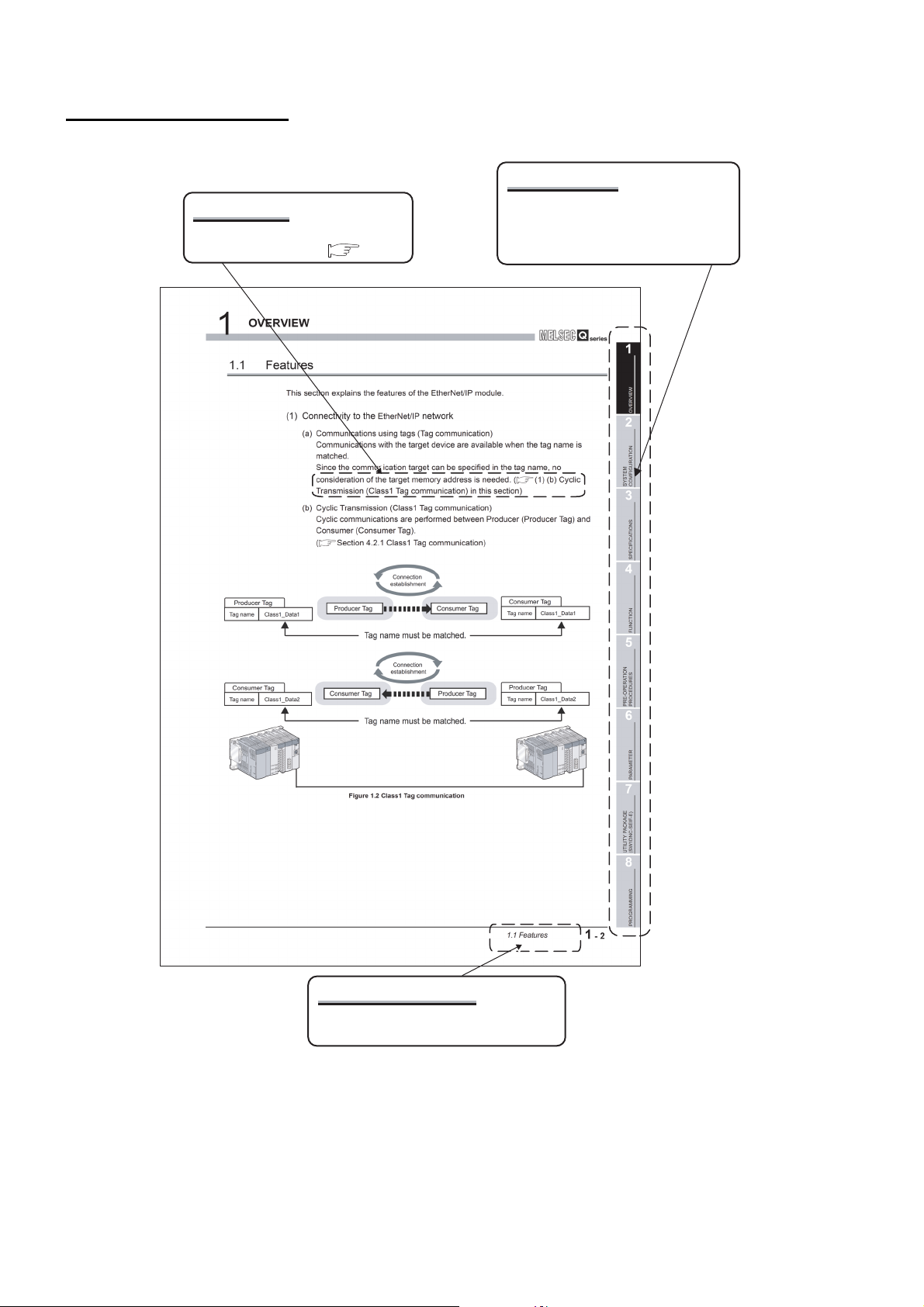
(a) Communications using tags (Tag communication)
Communications with the target device are available when the tag name is
matched.
Since the communication target can be specified in the tag name, no
consideration of the target memory address is needed. ( (1) (b) Cyclic
Transmission (Class1 Tag communication) in this section)
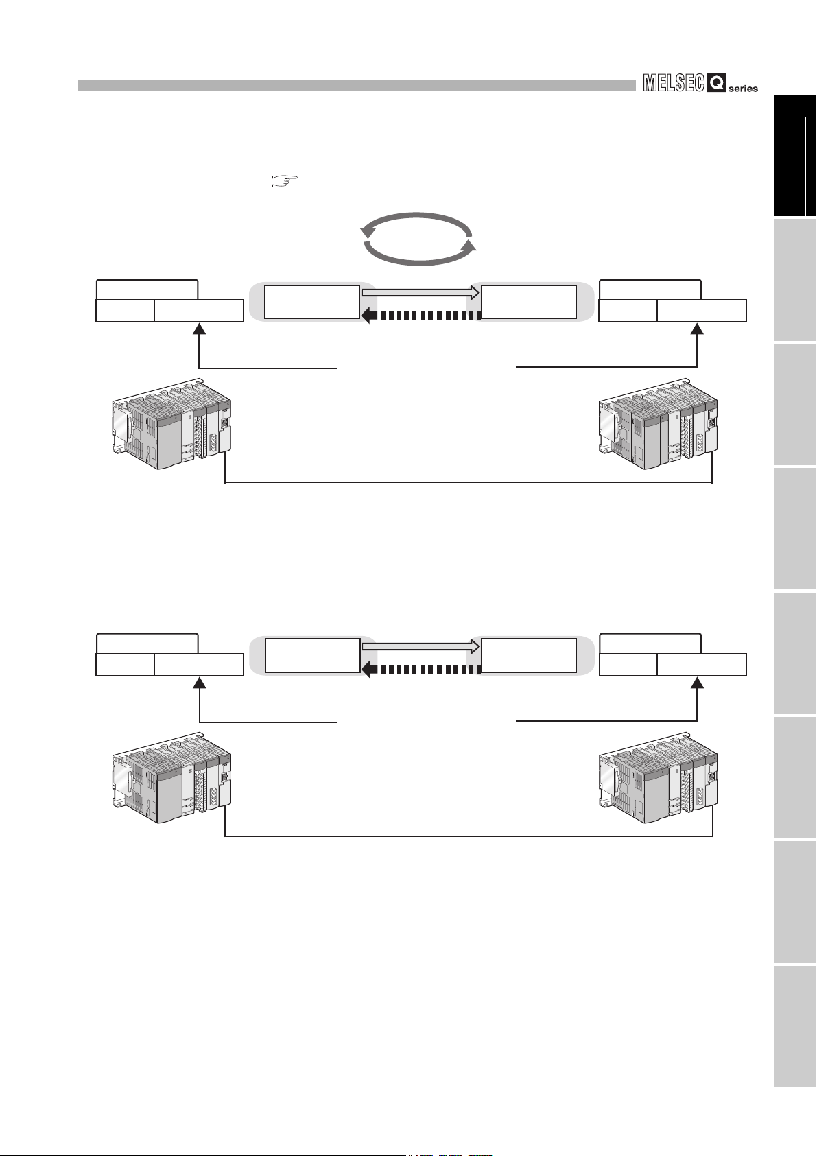
(b) Cyclic Transmission (Class1 Tag communication)
Cyclic communications are performed between Producer (Producer Tag) and
Consumer (Consumer Tag).
( Section 4.2.1 Class1 Tag communication)
Producer Tag
Tag name Class1_Data1
Consumer Tag
Tag name Class1_Data2
Connection
establishment
Producer Tag Consumer Tag
Tag name must be matched.
Connection
establishment
Producer TagConsumer Tag
Tag name must be matched.
Figure 1.2 Class1 Tag communication
Consumer Tag
Tag name Class1_Data1
Producer Tag
Tag name Class1_Data2
1 - 2
1.1 Features
1
Connection
establishment
Class3 Tag
Tag name
Class3_Data1
Class3 Tag
Class3 Tag
Tag name Class3_Data1
Class3 Tag
Read request
Read response
(Tag data read)
Tag name must be matched.
Read response
(Tag data read)
Tag name must be matched.
Read request
UCMM Tag UCMM Tag
UCMM Tag
Tag name UCMM_Data1
UCMM Tag
Tag name UCMM_Data1
OVERVIEW
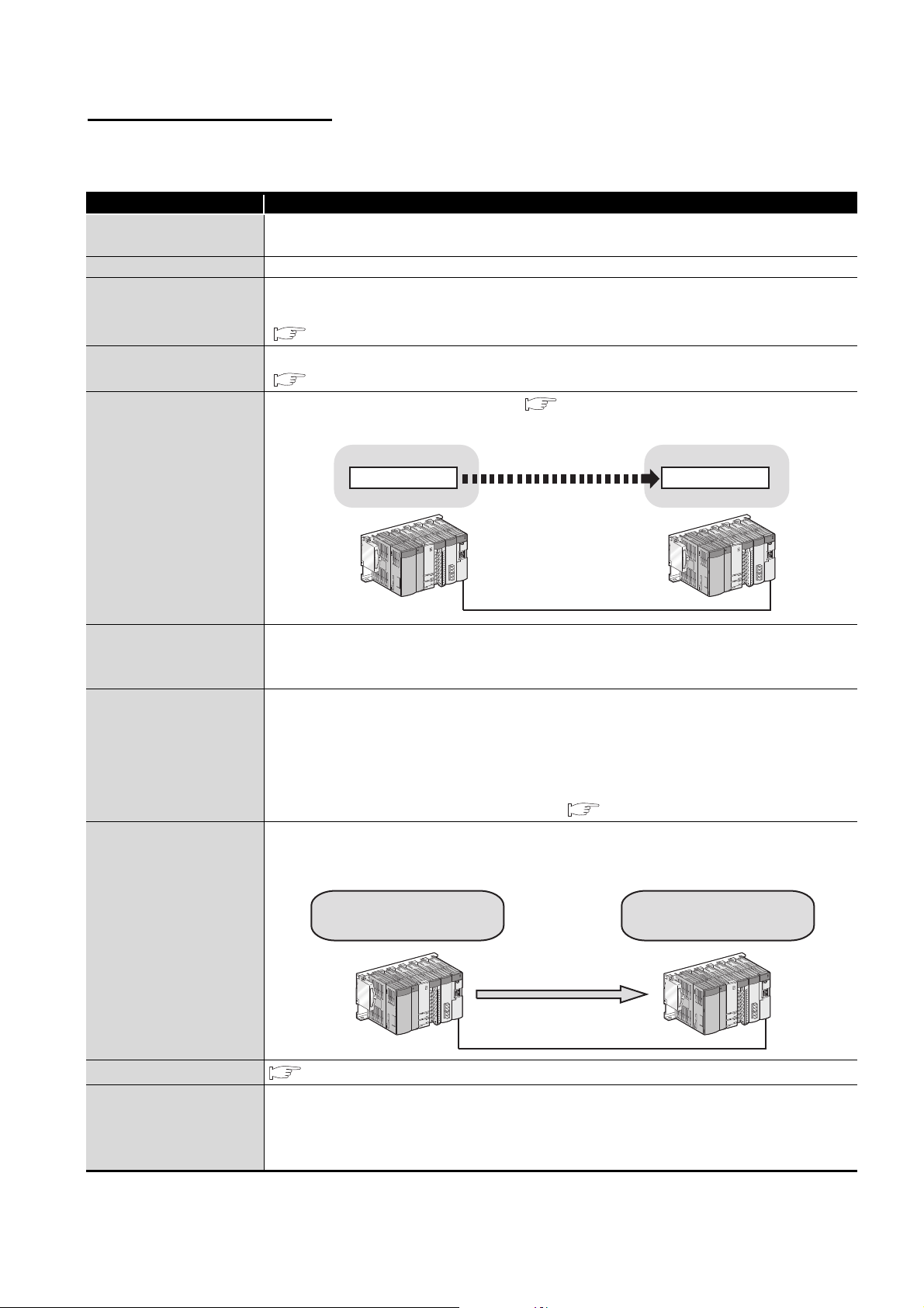
(c) Communications using read/write requests (Class3 Tag communication)
Communication can be performed by sending a read or write request.
( Section 4.2.2 Class3 Tag communication)
Figure 1.3 Class3 Tag communication
1
2
3
4
OVERVIEW
SYSTEM
CONFIGURATION
SPECIFICATIONS
(d) Asynchronous communication without establishing a connection (UCMM Tag
communication)
Communication using a read or write request is available without establishing a
connection prior to communication.
Figure 1.4 UCMM Tag communication
5
PRE-OPERATION
6
7
FUNCTION
PROCEDURES
PAR AMET ER
1.1 Features
UTILITY PACKAGE
(SW1DNC-EIPUTL-E)
8
PROGRAMMING
1 - 3
1
Producer Tag
(Class1 Tag
communication)
Consumer Tag
OVERVIEW
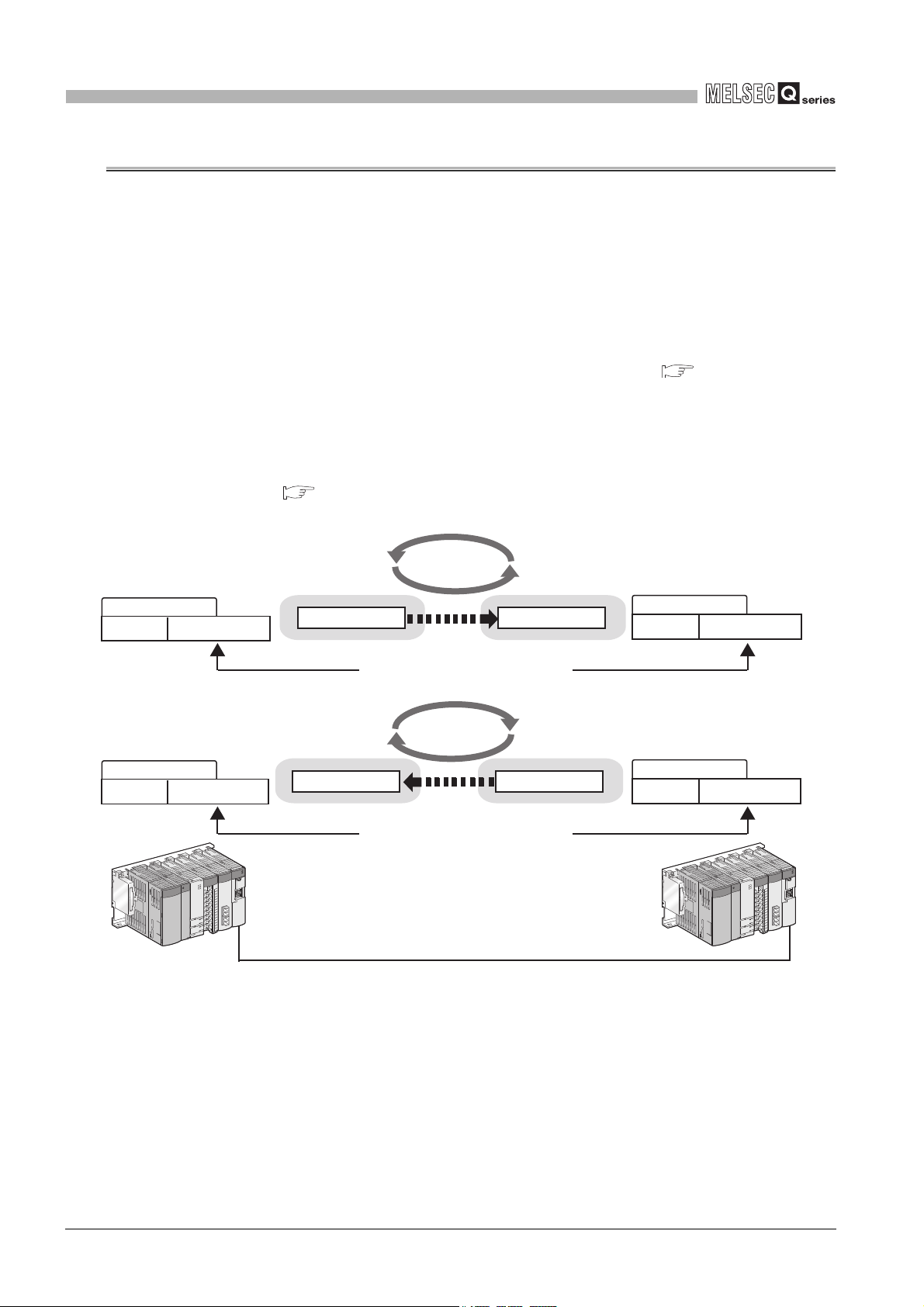
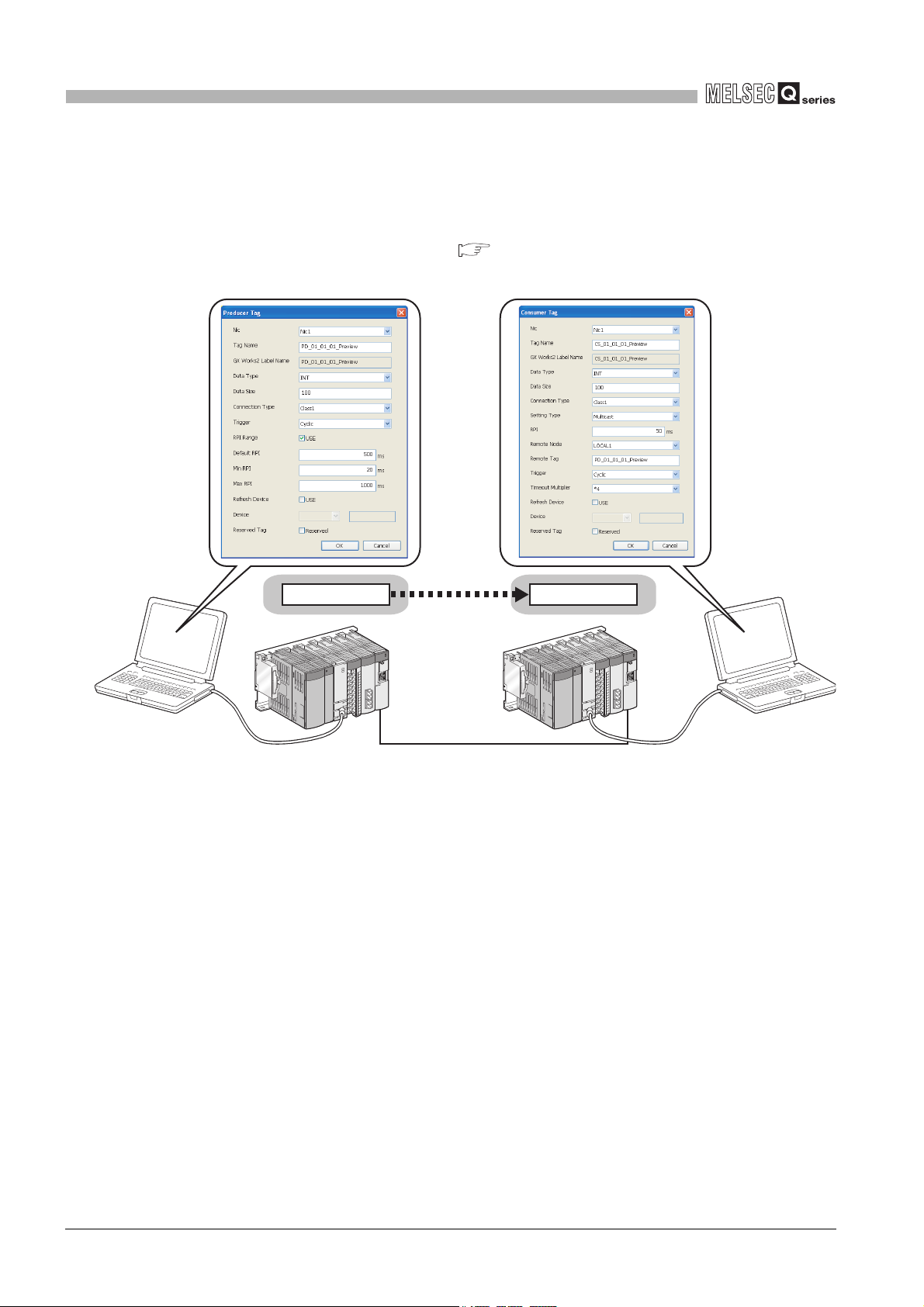
(2) Tag communication that does not need programming
(a) Tag communication by Utility Package setting only
Tag communication is available only by setting data such as IP addresses and tag
names in Utility Package. ( Section 4.2 Tag Communication Function, Section
7.9 "Setting" Tab (Parameter Settings))
Figure 1.5 Tag communication without programming
1 - 4
1.1 Features

1
Auto-refreshed
only by setting
Refresh target
device can be set.
QCPU EtherNet/IP module
Device
Producer Tag
(Class1 Tag
communication)
Consumer Tag
OVERVIEW
(b) Automatic refresh of tag data to QCPU devices
Tag data can be automatically refreshed into devices of a QCPU only by
configuring auto refresh settings in Utility Package.
( Section 7.9 "Setting" Tab (Parameter Settings))
1
2
3
4
OVERVIEW
SYSTEM
CONFIGURATION
SPECIFICATIONS
Figure 1.6 Setting example for auto refresh
5
PRE-OPERATION
6
7
UTILITY PACKAGE
8
FUNCTION
PROCEDURES
PAR AMET ER
(SW1DNC-EIPUTL-E)
1.1 Features
PROGRAMMING
1 - 5
1
Setting
for the 1st
module
Setting
for the 2nd
module
Setting
for the 3rd
module
Setting
for the 4th
module
OVERVIEW
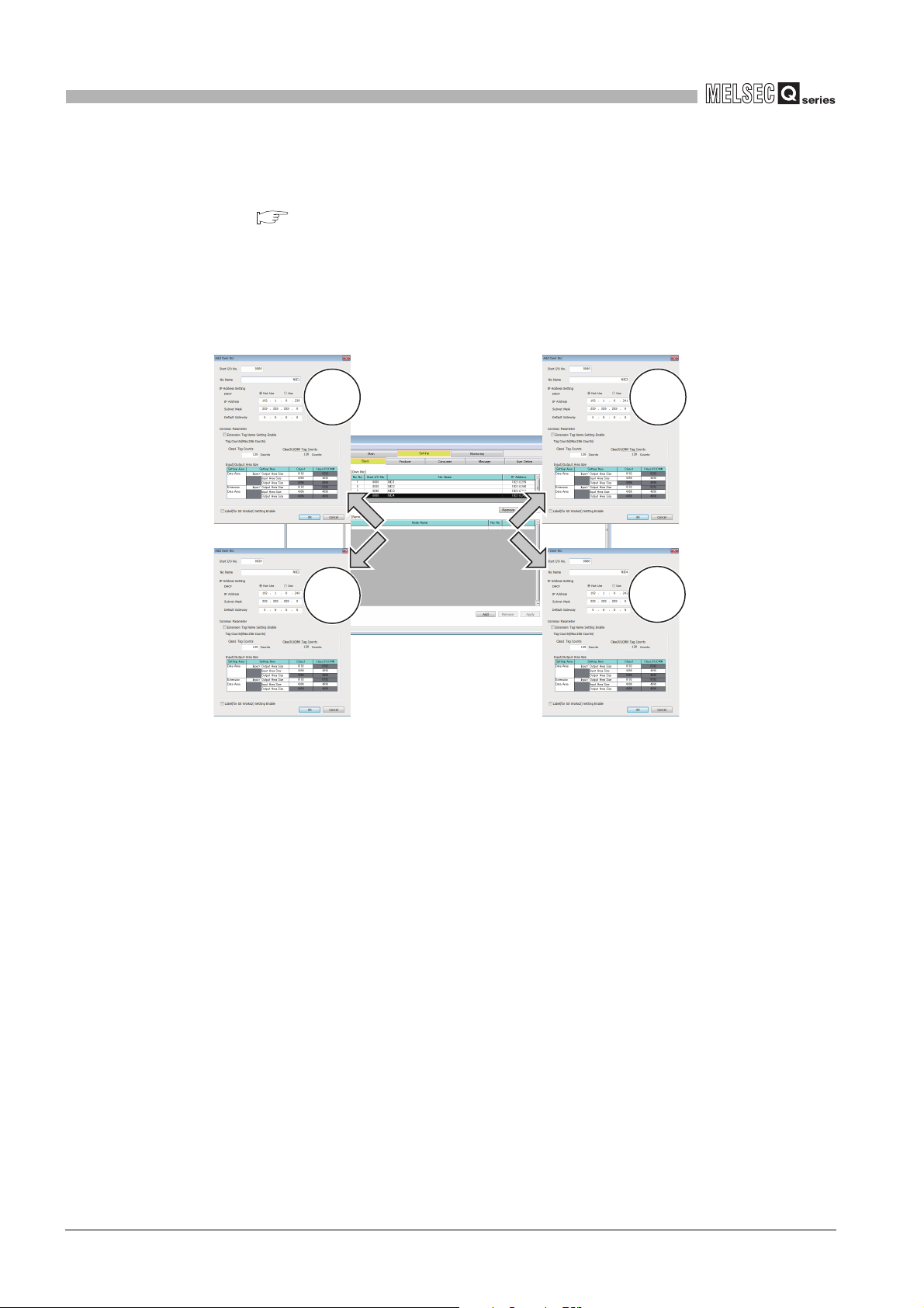
(3) Easy parameter setting
Utility Package allows easy parameter setting for the EtherNet/IP module.
( Section 7.9 "Setting" Tab (Parameter Settings))
The setting items are useful when the system is started up because they can be
checked in the list window (or list display).
When multiple EtherNet/IP modules are connected to one CPU module, settings can
be performed simultaneously for four modules per project.
Figure 1.7 Setting example of parameters
1 - 6
1.1 Features
1
OVERVIEW
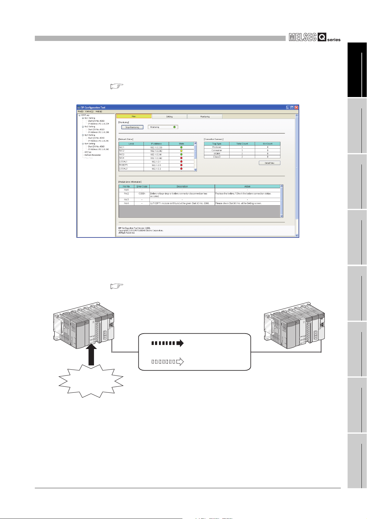
(4) Easy checking of errors and communication states
Errors and communication states can be easily checked with Utility Package.
( Section 7.6 "Main" Tab (Module Status Display))
The status of each tag can be viewed as well as the overall system status.
1
2
3
4
OVERVIEW
SYSTEM
CONFIGURATION
SPECIFICATIONS
(5) Tag communication status setting for a CPU stop error
The Tag communication status can be set to stop or continue in case a CPU stop
error occurs in the QCPU module mounted with the EtherNet/IP module.
( Section 4.3 Tag Communication Status Setting Function for CPU Stop Error)
Stop error occurred
(ERR.LED of CPU
module flashes.)
Figure 1.8 Checking errors and communication states
Continue
can be set!or
Stop
Figure 1.9 Tag communication for CPU stop error
5
PRE-OPERATION
6
7
FUNCTION
PROCEDURES
PAR AMET ER
1.1 Features
UTILITY PACKAGE
(SW1DNC-EIPUTL-E)
8
PROGRAMMING
1 - 7

2
SYSTEM CONFIGURATION
CHAPTER 2 SYSTEM CONFIGURATION
This chapter describes system configuration of the EtherNet/IP module.
2.1 Applicable Systems
This section describes the applicable systems
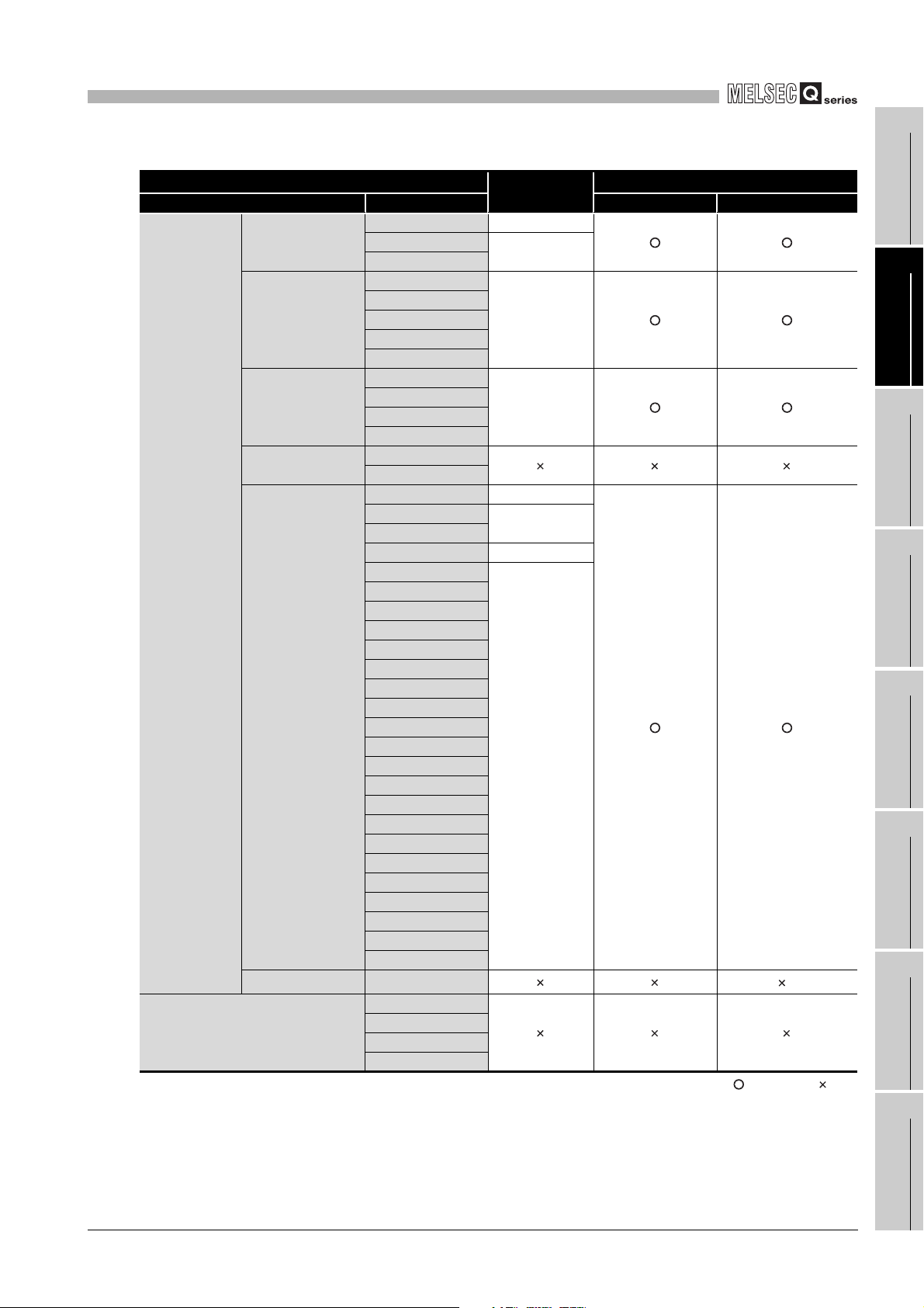
(1) Applicable modules and base units, and No. of modules
(a) When mounted with a CPU module
The following table lists the CPU modules and base units applicable to the
EtherNet/IP module and quantities for each CPU model.
Depending on the combination with other modules or the number of mounted
modules, power supply capacity may be insufficient.
Check the power supply capacity before mounting modules.
If the power supply is insufficient, change the combination of the modules.
2 - 1
2.1 Applicable Systems
2
SYSTEM CONFIGURATION
Programmable
controller CPU
C Controller module
Table 2.1 Applicable modules and base units, and No. of modules
Applicable CPU module
CPU type CPU model Main base unit Extension base unit
Q00JCPU Up to 8
Basic model QCPU
High Performance
model QCPU
Process CPU
Redundant CPU
Universal model
QCPU
Safety CPU QS001CPU
* 1 Limited within the range of I/O points for the CPU module.
* 2 Can be installed to any I/O slot of a base unit.
* 3 Extension base unit cannot be installed to a safety CPU.
Q00CPU
Q01CPU
Q02CPU
Q02HCPU
Q06HCPU
Q12HCPU
Q25HCPU
Q02PHCPU
Q06PHCPU
Q12PHCPU
Q25PHCPU
Q12PRHCPU
Q25PRHCPU
Q00UJCPU Up to 8
Q00UCPU
Q01UCPU
Q02UCPU Up to 36
Q03UDCPU
Q04UDHCPU
Q06UDHCPU
Q10UDHCPU
Q13UDHCPU
Q20UDHCPU
Q26UDHCPU
Q03UDECPU
Q04UDEHCPU
Q06UDEHCPU
Q10UDEHCPU
Q13UDEHCPU
Q20UDEHCPU
Q26UDEHCPU
Q50UDEHCPU
Q100UDEHCPU
Q03UDVCPU
Q04UDVCPU
Q06UDVCPU
Q13UDVCPU
Q26UDVCPU
Q06CCPU-V
Q06CCPU-V-B
Q12DCCPU-V
Q24DHCCPU-V
No. of modules
*1
Up to 24
Up to 64
Up to 64
Up to 24
Up to 64
Base unit
*2
*3
: Applicable, : N/A
1
2
SYSTEM
3
4
5
PRE-OPERATION
6
7
UTILITY PACKAGE
8
OVERVIEW
CONFIGURATION
SPECIFICATIONS
FUNCTION
PROCEDURES
PAR AMET ER
(SW1DNC-EIPUTL-E)
2.1 Applicable Systems
PROGRAMMING
2 - 2

2
SYSTEM CONFIGURATION
(b) Mounting to a MELSECNET/H remote I/O station
The EtherNet/IP module cannot be mounted to any MELSECNET/H remote I/O
station.
Mount it together with a CPU module.
(2) Support of the multiple CPU system
When using the EtherNet/IP module in the multiple CPU system, refer to the following
manual first.
QCPU User's Manual (Multiple CPU System)
(a) Applicable EtherNet/IP module
The function version of the EtherNet/IP module has been "B" from the first
release, which supports the multiple CPU system.
(b) Parameter writing from Utility Package
Write parameters only to the control CPU of the EtherNet/IP module.
(3) Applicable software packages
Systems using the EtherNet/IP module and applicable software versions are shown
below.
• GX Developer or GX Works2 (Required)
For setting parameters to a QCPU and creating sequence programs.
• Utility Package (SW1DNC-EIPUTL-E) (Required)
For setting parameters and monitoring.
Item
Q00J/Q00/Q01CPU
Q02/Q02H/Q06H/Q12H/Q25HC
PU
Q02PH/Q06PHCPU
Q12PH/Q25PHCPU
Q02U/Q03UD/Q04UDH/Q06UD
HCPU
Q13UDH/Q26UDHCPU
Q03UDE/Q04UDEH/Q06UDEH/
Q13UDEH/Q26UDEHCPU
Q00UJ/Q00U/Q01U/Q10UDH/Q
20UDH/Q10UDEH/Q20UDEHC
PU
Q50UDEH/Q100UDEHCPU
Q03UDV/Q04UDV/Q06UDV/Q1
3UDV/Q26UDVCPU
Table 2.2 Software packages
GX Developer GX Works2
Single CPU system Version 7 or later
Multiple CPU system Version 8 or later
Single CPU system Version 4 or later
Multiple CPU system Version 6 or later
Single CPU system
Multiple CPU system
Single CPU system
Multiple CPU system
Single CPU system
Multiple CPU system
Single CPU system
Multiple CPU system
Single CPU system
Multiple CPU system
Single CPU system
Multiple CPU system
Single CPU system
Multiple CPU system
Single CPU system
Multiple CPU system
Version 8.68W or later
Version 7.10L or later
Version 8.48A or later
Version 8.62Q or later
Version 8.68W or later
Version 8.76E or later
Cannot be used
Software version
Utility Package
(SW1DNC-EIPUTL-E)
Version 1.15R or later
Version 1.87R or later
Version 1.00A or later
Version 1.15R or later
Version 1.31H or later
Version 1.98C or later
2 - 3
2.1 Applicable Systems
 Loading...