

Page 1

C
MIT
SUBIS
C
HI ELECTRI
MELSEC System Q
Programmable Logic Controllers
User's Manual
DeviceNet Master-Slave Module
Art. no.: 139835
01 05 2003
SSH (NA)-080143
Version F
QJ71DN91
GX Configurator-DN
MITSUBISHI ELECTRI
INDUSTRIAL AUTOMATION
Page 2
SAFETY PRECAUTIONS
•
(Always read these instructions before using this equipment.)
Before using this product, please read this manual and the relevant manuals introduced in this manual
carefully and pay full attention to safety to handle the product correctly.
The instructions given in this manual are concerned with this product. For the safety instructions of the
programmable controller system, please read the User's Manual of the CPU module to use.
In this manual, the safety instructions are ranked as "DANGER" and "CAUTION".
•
DANGER
!
CAUTION
!
Note that the !CAUTION level may lead to a serious consequence according to t he circumstances.
Always follow the instructions of both levels because they are important to personal safety.
Please save this manual to make it accessible when required and always forw ard it to the end user.
Indicates that incorrect handling may cause hazardous conditions,
resulting in death or severe injury.
Indicates that incorrect handling may cause hazardous conditions,
resulting in medium or slight personal injury or physical damage.
[DESIGN PRECAUTIONS]
!
DANGER
If a communications error occurs to a device network, the node in such a communications error
•
will be in a state as follows:
(1) The master node (QJ71DN91) maintains input data which had been received from the slav e
node before the error occurred.
(2) Whether the slave node's output signal is turned off or maintained is determined by the
slave node's specifications or the parameters set at the master node. When using
QJ71DN91 as a slave node, the entered data from master node before the faulty node is
maintained.
By referring to communications states of the slave node, arrange an interlock circuit in a
sequential program and provide safety mechanism externally of the slave node in order the
system to operate safely.
!
CAUTION
Do not bunch the control wires or communication cables with the main circuit or power wires, or
•
install them close to each other.
They should be installed 300 mm (11.8 inch) or more from each other. Not doing so could result
in noise that may cause malfunction.
A - 1 A - 1
Page 3

[INSTALLATION PRECAUTIONS]
!
CAUTION
Use the PLC in an environment that meets the general specifications contained in the CP U
•
User's Manual to use.
Using this PLC in an environment outside the range of the general specific ations may cause
electric shock, fire, malfunction, and damage to or deterioration of the product.
When installing the module, securely insert the module fixing tabs into the mountin g holes of the
•
base module while pressing the installation lever located at the bottom of the module downward.
Improper installation may result in malfunction, breakdown or dropping out of the module.
Securely fix the module with screws if it is subject to vibration during use.
Tighten the screws within the range of specified torque.
•
If the screws are loose, it may cause fallout, short circuits, or malfunction.
If the screws are tightened too much, it may cause damage to the screw and /or the module,
resulting in fallout, short circuits or malfunction.
Switch all phases of the external power supply off when mounting or removing the module.
•
Not doing so may cause electric shock or damage to the module.
Do not directly touch the conductive area or electric components of the module.
•
Doing so may cause malfunction or failure in the module.
[WIRING PRECAUTIONS]
!
DANGER
Make sure to shut off all the phases of the external power supply before starting installation or
•
wiring. Otherwise, the personnel may be subjected to an electric shock or the product to a
damage.
!
CAUTION
Be careful not to let foreign matters such as sawdust or wire chips get inside the module.
•
These may cause fires, failure or malfunction.
The top surface of the module is covered with protective film to prevent foreign objects such as
•
cable offcuts from entering the module when wiring.
Do not remove this film until the wiring is complete.
Before operating the system, be sure to remove the film to provide adequate heat ventilation.
Be sure to fix cables leading from the module by placing them in the duct or clamping them.
•
Unless the cables are placed with a duct or clamped, the module or cables could be broken by
swinging or moving of the cables or unintentional pulling to cause an operation error result ing
from a contact error.
Do not pull cables by holding them with a hand for removing the cables that are connected to the
•
module. To remove a cable having a connector, hold the connector connected to the module
with a hand. To remove a cable not having a connector, loosen the screws fastening to connect
the module. The cables being pulled while t hey are still connect ed to the module cou ld break the
module or cables, or cause an operation error resulting from a contact error.
A - 2 A - 2
Page 4

[CAUTIONS ON STARTUP AND MAINTENANCE]
!
DANGER
Always turn off all external power supply phases before touching any terminals.
•
Failure to do this may result in malfunction.
Always turn of all external power supply phases before cleaning or tightening the terminal
•
screws.
Failure to do this may result in malfunction.
Do not disassemble or modify any module.
•
This will cause failure, malfu nction, injur ies, or fire.
Always turn off all external power supply phases before mounting or dismounting the module.
•
Failure to do this may result in malfunction or damage to the module.
Always make sure to touch the grounded metal to discharge the electricity charged in the body,
•
etc., before touching the module.
Failure to do so may cause a failure or malfunctions of the module.
[DISPOSAL PRECATION]
!
CAUTION
Dispose of this product as industrial waste.
•
A - 3 A - 3
Page 5
REVISIONS
The manual number is given on the bottom left of the back cover.
Print Date Manual Number Revision
Dec., 2000 SH (NA)-080143-A First Printing
Jun., 2001 SH (NA)-080143-B
Addition
Section 2.3, 2.4
Delete
Section 2.2.1, 2.2.2
Correction
SAFETY PRECAUTIONS, About the Generic Terms and Abbreviations,
Product Configuration, Section 2.2, 2.4, Section 6.2, 6.2.1, 6.2.2, 6.3.3,
6.5
Feb., 2002 SH (NA)-080143-C
Dec., 2002 SH (NA)-080143-D
Feb., 2003 SH (NA)-080143-E
May., 2003 SH (NA)-080143-F
Correction
About the Generic Terms and Abbreviations, Section 2.2, Section 6.2.1,
6.2.2
Addition
Section 2.5
Correction
Section 2.2, Section 3.3.2, 3.4.1, Section 6.1, 6.2.1, 6.3.2, 6.4, 6.5,
Section 9.2.1, 9.2.2
Correction
SAFETY PRECAUTIONS, INTRODUCTION, CONTENTS, Section 6.2.2,
Section 6.3.3, Section 6.4, Section 6.5
Correction
Section 6.3.1
Japanese Manual Version SH-080125-F
This manual confers no industrial property rights or any rights of any other kind, nor does it confer any patent
licenses. Mitsubishi Electric Corporation cannot be held responsible for any problems involving industrial property
rights which may occur as a result of using the contents noted in this manual.
2000 MITSUBISHI ELECTRIC CORPORATION
A - 4 A - 4
Page 6

INTRODUCTION
Thank you for purchasing the MELSEC-Q series PLC.
Before using the equipment. please read this manual carefully to develop full familiarity with the functions
and performance of the Q series PLC you have purchased, so as to ensure correct use.
CONTENTS
SAFETY PRECAUTIONS..............................................................................................................................A- 1
REVISIONS....................................................................................................................................................A- 4
INTRODUCTION............................................................................................................................................A- 5
CONTENTS....................................................................................................................................................A- 5
Conformation to the EMC Directive and Low Voltage Instruction ................................................................A- 8
About the Generic Terms and Abbreviations ................................................................................................A- 8
Product Configuration ....................................................................................................................................A- 9
1 OVERVIEW 1- 1 to 1- 2
1.1 Features ...................................................................................................................................................1- 1
2 SYSTEM CONFIGURATION 2- 1 to 2- 6
2.1 Overall Configuration ...............................................................................................................................2- 1
2.2 Applicable Systems..................................................................................................................................2- 3
2.3 How to Check the Function Version, Serial No. and Software Version .................................................2- 4
2.4 About Use of the QJ71DN91 with the Q00J/Q00/Q01CPU ...................................................................2- 5
2.5 About Additional Function........................................................................................................................2- 6
2.6 Compatible DeviceNet Products from Other Manufacturers..................................................................2- 6
3 SPECIFICATION S 3- 1 to 3- 51
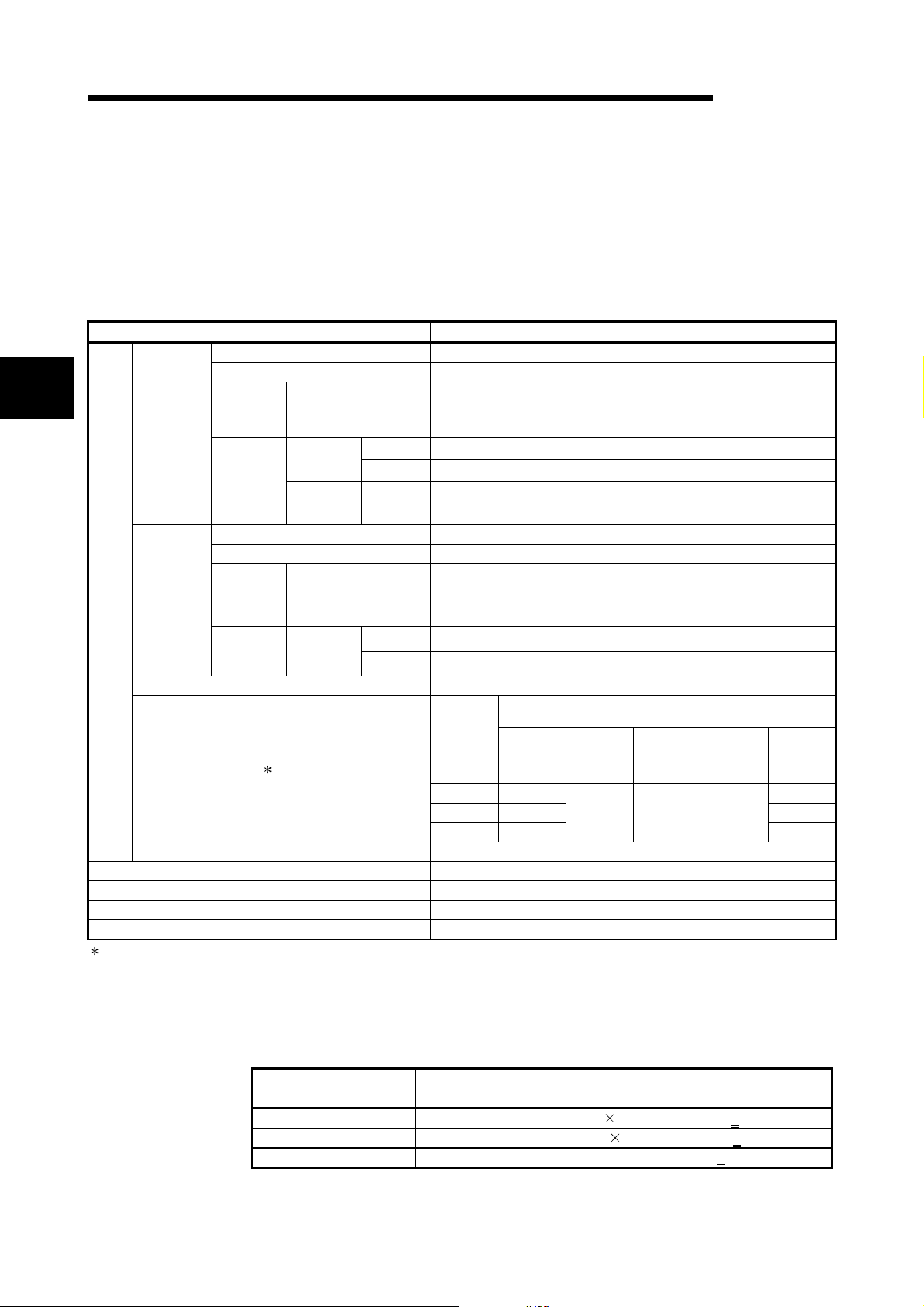
3.1 Performance Specifications..................................................................................................................... 3- 1
3.1.1 Maximum transmitting distance when thick and thin cables coexist...............................................3- 1
3.2 Functions..................................................................................................................................................3- 2
3.2.1 Master function (I/O communication function)..................................................................................3- 2
3.2.2 Master function (Message communication function) .......................................................................3- 8
3.2.3 Slave function (I/O communication function)....................................................................................3-11
3.3 I/O Signals for the PLC CPU ...................................................................................................................3-13
3.3.1 I/O signal list......................................................................................................................................3-13
3.3.2 Details of the I/O signals ...................................................................................................................3-14
3.4 Buffer Memory..........................................................................................................................................3-24
3.4.1 Buffer memory list .............................................................................................................................3-24
3.4.2 Buffer memory details .......................................................................................................................3-26
3.5 Communication Performance..................................................................................................................3-50
3.5.1 Scan time........................................................................................................................................... 3-50
3.5.2 Communication cycle........................................................................................................................3-51
3.5.3 Transmission delays .........................................................................................................................3-51
A - 5 A - 5
Page 7

4 SETUP AND PROCEDURES BEFORE OPERATION 4- 1 to 4- 14
4.1 Setup and Procedures before Operation ................................................................................................4- 1
4.1.1 When using the master function.......................................................................................................4- 1
4.1.2 When using the slave function..........................................................................................................4- 2
4.1.3 When using both the master function and slave function................................................................ 4- 3
4.2 Loading and Installation...........................................................................................................................4- 4
4.2.1 Handling precautions ........................................................................................................................4- 4
4.2.2 Installation environment ....................................................................................................................4- 4
4.3 Component Names and Settings ............................................................................................................4- 5
4.3.1 Meanings of the LED displays..........................................................................................................4- 6
4.3.2 Node number setting switch..............................................................................................................4- 7
4.3.3 Mode switch.......................................................................................................................................4- 7
4.4 Hardware Test..........................................................................................................................................4- 8
4.5 Connecting the Communication Cables to the QJ71DN91....................................................................4- 9
4.6 Communication Test...............................................................................................................................4- 10
4.7 Instructions for Connecting the Network Power Supply ........................................................................4- 11
4.7.1 Network power supply unit installation position...............................................................................4- 11
4.7.2 Calculating network power supply unit installation position and current capacity..........................4- 12
5 PARAMETER SETTINGS 5- 1 to 5- 6
5.1 Description of Parameter Settings...........................................................................................................5- 1
5.1.1 Parameters for the master function ..................................................................................................5- 1
5.1.2 Parameters for the slave function.....................................................................................................5- 2
5.1.3 Common parameters for the master/slave functions.......................................................................5- 2
5.2 Setting Using the Sequence Program.....................................................................................................5- 2
5.3 Setting Using the Auto Configuration Function.......................................................................................5- 3
6 UTILITY PACKAGE (GX Configurator-DN) 6- 1 to 6- 21
6.1 Functions of the Utility Package..............................................................................................................6- 1
6.2 Installing and Uninstalling the Utility Package.........................................................................................6- 2
6.2.1 User precautions ............................................................................................................................... 6- 2
6.2.2 Operating environment...................................................................................................................... 6- 4
6.3 Explanation of Utility Package Operation................................................................................................6- 5
6.3.1 How to perform common utility package operations........................................................................ 6- 5
6.3.2 Overview of operation .......................................................................................................................6- 8
6.3.3 Starting the intelligent function module utility..................................................................................6- 10
6.4 Auto Refresh Settings.............................................................................................................................6- 12
6.5 Monitor/Test ............................................................................................................................................6- 14
6.6 Flash ROM Settings................................................................................................................................6- 20
A - 6 A - 6
Page 8

7 PROGRAMMING WHEN EXECUTING THE MASTER FUNCTION 7- 1 to 7- 12
7.1 Precautions on Programming.................................................................................................................. 7- 1
7.2 System Configuration...............................................................................................................................7- 2
7.3 Setting Parameters ..................................................................................................................................7- 4
7.3.1 Parameter settings using the sequence program............................................................................7- 4
7.3.2 Creating parameters using auto configuration.................................................................................7- 6
7.3.3 Saving parameters in flash ROM......................................................................................................7- 6
7.4 I/O Communication with Slave Nodes.....................................................................................................7- 7
7.5 Performing Message Communication.....................................................................................................7- 8
7.5.1 Example of message communication read......................................................................................7- 8
7.5.2 Example of message communication write......................................................................................7- 9
7.6 Obtaining Error Information ....................................................................................................................7- 10
7.7 Allocating Transmission/Reception Data Storage Devices for Future Expansion................................7- 11
8 PROGRAMMING WHEN EXECUTING THE SLAVE FUNCTION 8- 1 to 8- 4
8.1 System Configuration...............................................................................................................................8- 1
8.2 Setting Parameters Using the Sequence Program.................................................................................8- 2
8.3 I/O Communication with the Master Node ..............................................................................................8- 3
8.4 Obtaining Error Information .....................................................................................................................8- 4
9 TROUBLESHOOTING 9- 1 to 9- 12
9.1 Items to Check When an Error Occurs ...................................................................................................9- 2
9.1.1 Checking the LEDs ...........................................................................................................................9- 2
9.1.2 When communication with all slave nodes cannot be performed (using the master function) ......9- 3
9.1.3 When communication with a specific slave node cannot be performed
(using the master function)................................................................................................................9- 4
9.1.4 When communication with the master node cannot be performed (using the slave function).......9- 5
9.2 Error Codes..............................................................................................................................................9- 6
9.2.1 Communication error codes..............................................................................................................9- 6
9.2.2 Execution error codes of message communication (using the master function only) ....................9- 9
9.3 Verifying the QJ71DN91 Status on the GX Developer System Monitor...............................................9- 11
APPENDIX App- 1 to App- 7
Appendix 1 External Dimension Diagram .................................................................................................App- 1
Appendix 2 Differences between the QJ71DN91 and the AJ71DN91/A1SJ71DN91.............................App- 2
Appendix 3 Parameter Setting Sheet (For the Master Function).............................................................App- 3
Appendix 4 Parameter Setting Sheet (For the Slave Function) ...............................................................App- 4
Appendix 5 List of Communication Parameters of Slave Nodes Manufactured by Various
Manufacturers .........................................................................................................................App- 5
Appendix 6 EDS File of the QJ71DN91 ....................................................................................................App- 6
INDEX Index- 1 to Index- 2
A - 7 A - 7
Page 9

Conformation to the EMC Directive and Low Voltage Instruction
For details on making Mitsubishi PLC conform to the EMC directive and low voltage instruction when
installing it in your product, please see Chapter 3, "EMC Directive and Low Voltage Instruction" of the User's
Manual (Hardware) of the PLC CPU to use.
The CE logo is printed on the rating plate on the main body of the PLC that conforms to the EMC directive
and low voltage instructi on.
BY making this product conform to the EMC directive and low voltage instruc ti on, it is not neces s ary to make
those steps individually.
About the Generic Terms and Abbreviations
Unless otherwise specified, this manual uses the following generic terms and abbreviations to explain
QJ71DN91 DeviceNet Master·S la ve Mo dul e.
Generic Term/Abbreviation Description
Generic product name of the product types SWnD5C-GPPW-E, SWnD5C-GPPW-EA,
GX Developer
QCPU (Q mode)
GX Configurator-DN
QJ71DN91 Abbreviation for QJ71DN91 DeviceNet Master-Slave Module
Personal computer IBM PC/AT® or compatible computer with DOS/V.
SWnD5C-GPPW-EV and SWnD5C-GPPW-EVA.
"n" in the model is 4 or greater.
Generic term for Q00JCPU, Q00CPU, Q01CPU, Q02CPU, Q02HCPU, Q06HCPU,
Q12HCPU, Q25HCPU, Q12PHCPU, Q25PHCPU
Abbreviation for DeviceNet Master-Slave Module setting/Monitor Tool GX
Configurator-DN (SW1D5C-QDNU-E)
A - 8 A - 8
Page 10

Product Configuration
The following is a list of the components in this product configuration.
Model name Product name Quantity
QJ71DN91 DeviceNet master-slave module
QJ71DN91
Terminal resistor 121Ω, 1/4W
Connector
SW1D5C-QDNU-E GX Configurator-DN Version 1 (1-license product) (CD-ROM) 1
SW1D5C-QDNU-EA GX Configurator-DN Version 1 (Multiple-license product) (CD-ROM) 1
1
2
1
A - 9 A - 9
Page 11
1 OVERVIEW
1 OVERVIEW
MELSEC-Q
1
1.1 Features
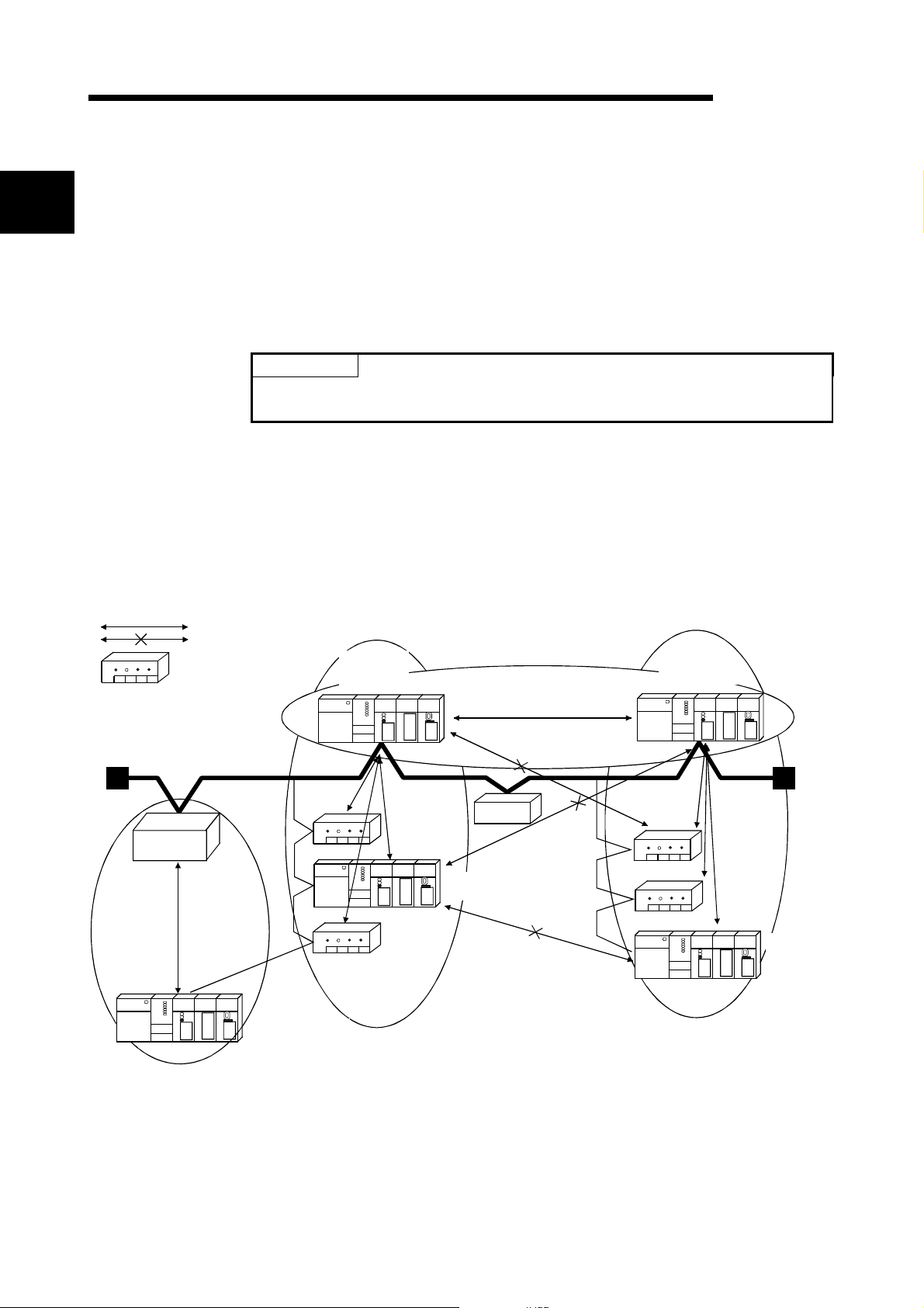
Master station
This manual explains the specifications and name of each component of the
QJ71DN91 DeviceNet master/slave module, which is used in combination with the
MELSEC-Q Series PLC CPU.
Please see Device Ne t Sp e ci ficat io n Ma nu al (Rel ea se 2. 0), Volu mes 1 a nd 2, fo r th e
specifications of DeviceNet.
DeviceNet is a registered trademark of Open DeviceNet Vendor Association, Inc.
This section explains the features of the QJ71DN91.
(1) The module conforms to the DeviceNet Specifications Manual (Release 2.0).
(2) The module can function as a master node, slave node, or master/slave node of
MS
Slave side
I/O communication between the master station and slave sta t i on i s possible.
Communication is not possible.
: DeviceNet slave
POINT
Most of the DeviceNet products on the market are assumed to be compatible.
However, compatibility with the products of other manufacturers is not guaranteed.
DeviceNet.
QJ71DN91
master
(Node No. 5)
M
S
QJ71DN91
master + slave
(Node No. 6)
Master made by
other manufacturer
(Node No. 10)
M
S
(Node No. 2)
S
M
S
(Node No. 4)
S
QJ71DN91 slave
(Node No. 1)
24V power
supply
QJ71DN91 slave
(Node No. 3)
S
M
(Node No. 7)
S
(Node No. 8)
S
QJ71DN91
slave
(Node No. 9)
(3) The paramete rs of QJ71D N91 can be se t by any of th e foll ow in g th re e meth od s:
• Setting the parameters using GX Configurator-DN
• Setting the parameters using the TO instruction of a sequence program
• Setting the parameters using auto configuration
1 - 1 1 - 1
Page 12
1 OVERVIEW
MELSEC-Q
(4) When the module functions as a master node of DeviceNet, I/O communication
and message communication with a DeviceNet slave node are possible.
(5) When the module functions as a master node of DeviceNet, the module can
communicate with a maxi mum of 6 3 slav e node s.
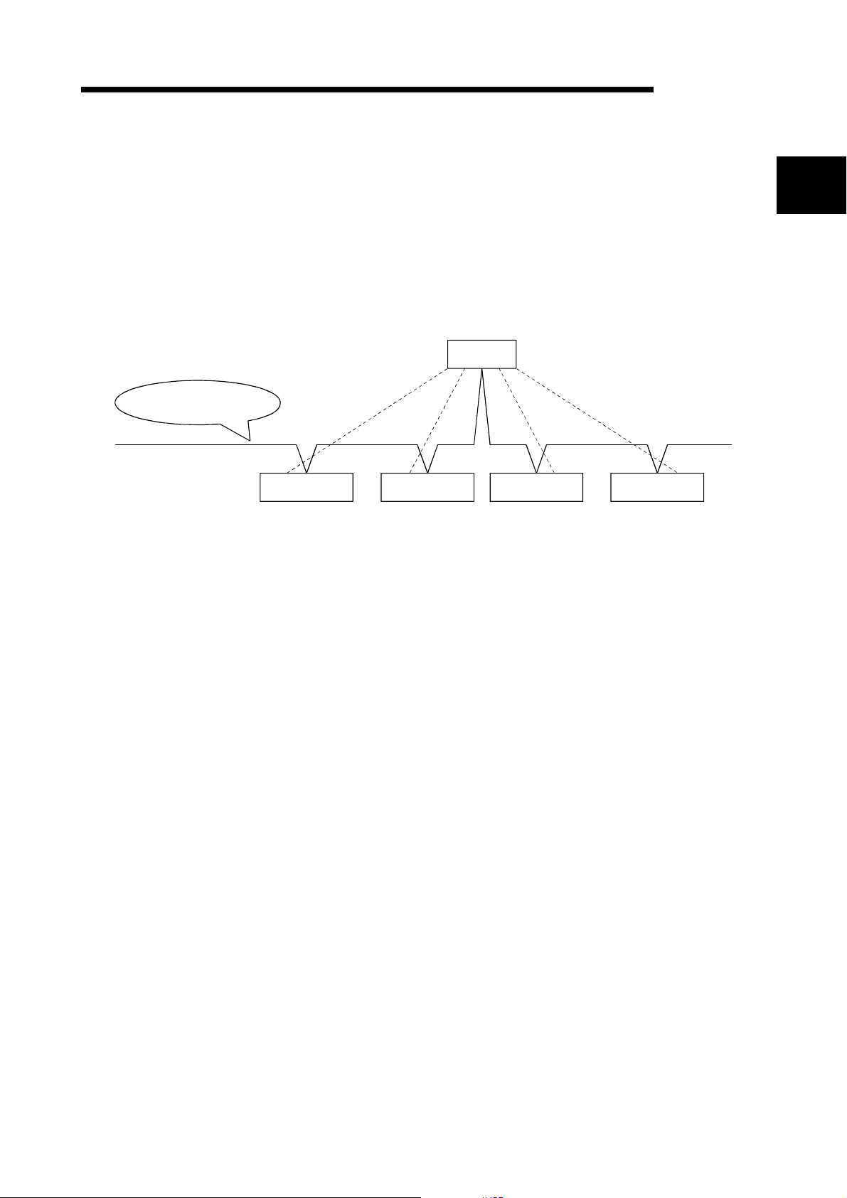
(6) Selection is available from four types of I/O communication methods when this
module functions as a master node in DeviceNet. They are polling, bit strobe,
change-of-state and cyclic which are defined in DeviceNet.
However, only one type o f communi ca ti on met h od ca n be sel e cted fo r each slave
node.
QJ71DN91
1
DeviceNet network
Polling
Bit strobe Cyclic
Slave node 1 Slave node 2 Slave node 3 Slave node 4
Change-of-state
For I/O communication, see Section 3.2.1.
(7) When the module functions as a master node of DeviceNet, an I/O communication
with input of 256 words (4,096 points) and output of 256 words (4,096 points) can
be performed.
(8) When the module functions as a master node of DeviceNet, a message
communication of 240 byte data can be performed at one time.
(9) When the module functions as a slave node of DeviceNet, I/O communication with
input of 64 words (1,024 points) and output of 64 words (1,024 points) can be
performed.
(10) When the module functions as a slave node of DeviceNet, I/O communication can
be performed via polling.
1 - 2 1 - 2
Page 13
2 SYSTEM CONFIGURATION
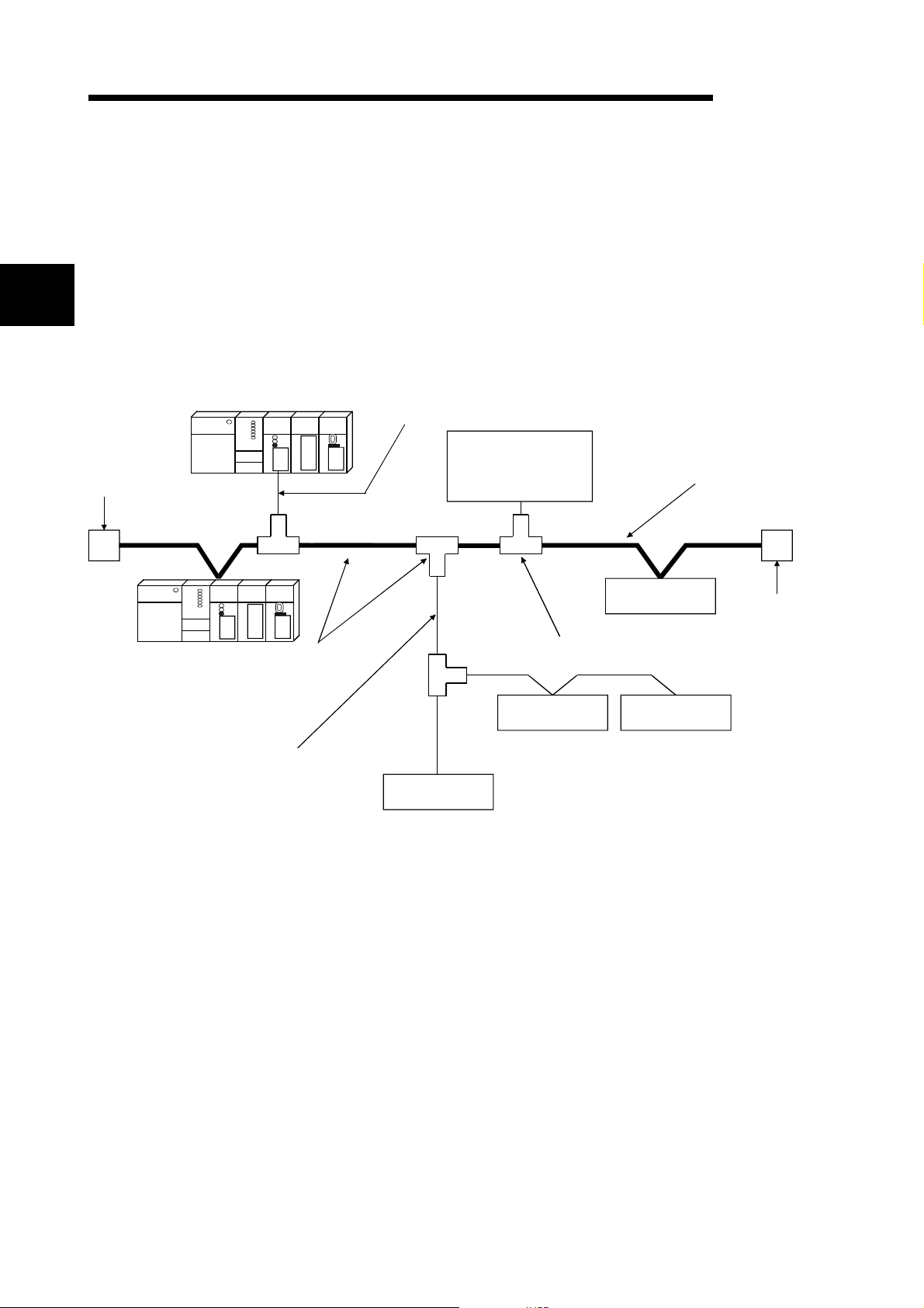
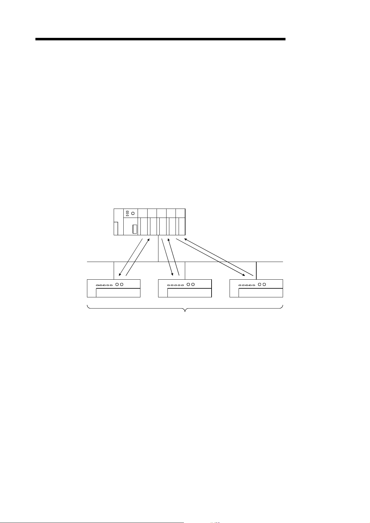
2 SYSTEM CONFIGURATION
This chapter explains the system configuration of DeviceNet.
2.1 Overall Configuration
MELSEC-Q
2
Terminal resistor
(121Ω, 1/4W)
Slave node
Master node
A total of 64 modules including a master node, slave nodes and a master/slave node
can be connected.
Each node is connected via a tap from the trunk line or directly to the trunk line.
The following shows an example of a system configuration:
Drop line
Network power-supply
Tap
module (24V DC)
Power supply tap
Slave node Slave node
Trunk line (main line)
Slave node
Terminal resistor
(121Ω, 1/4W)
Drop line (branch line)
1) The QJ71DN91 can be used a s a maste r node , a sl a ve no de or a
2) A combined maximum of 64 master node and slave nodes can be
3) There is no need to connect the master node and slave nodes in the
4) The network cable consists of trunk line (main line) and drop lines
5) It is necessary to connect the network power supply in order to supply
6) Use the terminal resistors included in the package, or they must be
Slave node
master/slave no de .
connected.
order of node number.
(branch lines).
Terminal resistors are required on both sides of the trunk line.
the power supply to the communication circuit in addition to the
operating power supply of each node.
furnished by the user.
2 - 1 2 - 1
Page 14

2 SYSTEM CONFIGURATION
(1) Network specification
The following explains the network specifications of DeviceNet that uses the
QJ71DN91.
(a) Communication speed
The communication speed can be selected from 125kbaud, 250kbaud, or
500kbaud using the mode switch of the QJ71DN91.
The maximum cable length va ri e s depe ndin g on th e co mmunication speed.
See Section 3.1, "Performance Specifications" for details.
(b) Supplying power to the network
The following de scri be s th e met h od o f supp ly ing ne two r k powe r to each
node:
1) Connect a dedicated power supply tap to the trunk-line cable and install
2) The power is supplied from the network power-supply module to each
Remarks
MELSEC-Q
2
the network p owe r -s up ply mod ul e.
node via the network cable.
Inquire to ODVA about the following devices required to construct a DeviceNet
network.
• Network power-supply module
• Power supply tap
• Tap
• Terminal resistor
• Network cable
Contact at ODVA is as follows:
Open DeviceNet Vendor Association, Inc.
Address
20423 State Ro ad 7 - Sui te 499 - B o ca Ra to n, FL 33 49 8 U.S .A.
TEL. +1-954-340-5412
FAX. +1-954-340-5413 or +1-561-477-6621
2 - 2 2 - 2
Page 15
2 SYSTEM CONFIGURATION
2.2 Applicable Systems
This section describes the system configuration for the QJ71DN91.
(1) Applicable module and the nu mber of modules that can be installed
The following are the CPU module in which the QJ71DN91 can be installed and
the number of modules that can be installed.
MELSEC-Q
CPU module
1 See User's Manual (Function Explanation, Program Fundamentals) for the CPU module to use.
Applicable module
Q12PHCPU
Q25PHCPU
Number of modules that
can be installed
Q00JCPU Maximum 16
Q00CPU
Q01CPU
Q02CPU
Q02HCPU
Q06HCPU
Q12HCPU
Q25HCPU
Maximum 24
Maximum 64
Maximum 64
Can be installed in Q mode only
1
(
Remarks
(
)
(
(2) Base unit in which the conversion modul e can be i nstall ed
The QJ71DN91 can be installed in any I/O slot ( 2) of the base unit. However, a
power shortage may occur depending on the combination with other installed
modules and the number of modules used, so always take into consideration the
power supply capa city when installing modules.
2 Limited to the range of the number of I/O points in the CPU module.
(3) Compatibility with a multiple PLC system
First read the QCPU (Q mode) (Function Explanation, Program Fundamentals)
User's Manual if the QJ71DN91 is used with a multiple PLC system.
(a) Compatible QJ71DN91
Use a QJ71DN91 with function version B or higher if using the module in a
multiple PLC system.
1
)
1
)
(b) Intelligent function module parameters
Perform PLC write of the intelligent function module parameters to the
control PLC of the QJ71DN91 only.
2 - 3 2 - 3
Page 16
2 SYSTEM CONFIGURATION
(4) Software packages supported
Correspondence between systems which use QJ71DN91s and software
packages are as shown below.
The GX Developer is necessary when using a QJ71DN91.
GX Developer
Software Version
GX Configurator-DN
MELSEC-Q
2
Q00J/Q00/
Q01CPU
Q02/Q02H/
Q06H/Q12H/
Q25HCPU
Q12PH/
Q25PHCPU
2 Version 1.14Q or earlier is incompatible with Each Node Communi cation Error Status
Single PLC system Version 7 or later
Version 1.10L or later
Multiple PLC system Version 8 or later
Single PLC system Version 4 or later Version 1.00A or later
Multiple PLC system Version 6 or later Version 1.10B or later
Single PLC system
Version 7.10L or later Version 1.13P or later
Multiple PLC system
(addresses 1C0
H
to 1C3H/448 to 451). Use the product of Version 1.15R or later.
(5) Precautions on wiring
In order to avoid the effects of noise, the DeviceNet communication cable, power
cable and signal lines for the I/O module should be installed in such a way that
they are sufficiently away from each other.
(6) Remote operation is not allowed from other DeviceNet node
Each DeviceNet node on DeviceNet cannot read/write/monitor the sequence
program or data of the PLC CPU where the QJ71DN91 is installed.
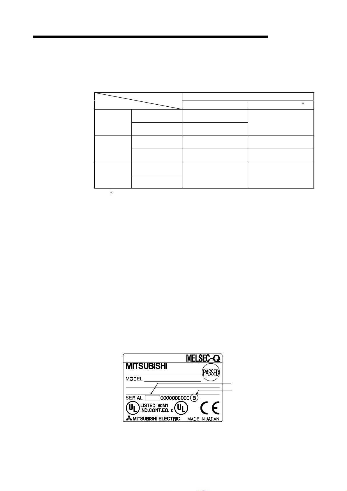
2.3 How to Check the Function Version, Serial N o. and Softwar e Ver si on
This section describes how to check the function version and serial No. of the
QJ71DN91 and the GX Configurator-DN software version.
(1) How to check the function version and serial No. of the QJ71DN91
(a) To check the version using the "SERIAL column of the rating plate" located
on the side of the module
(b) To check the version using the GX Developer
See Section 9.3 of this manual.
Serial No. (first 5 digits)
Function version
03052
2 - 4 2 - 4
Page 17
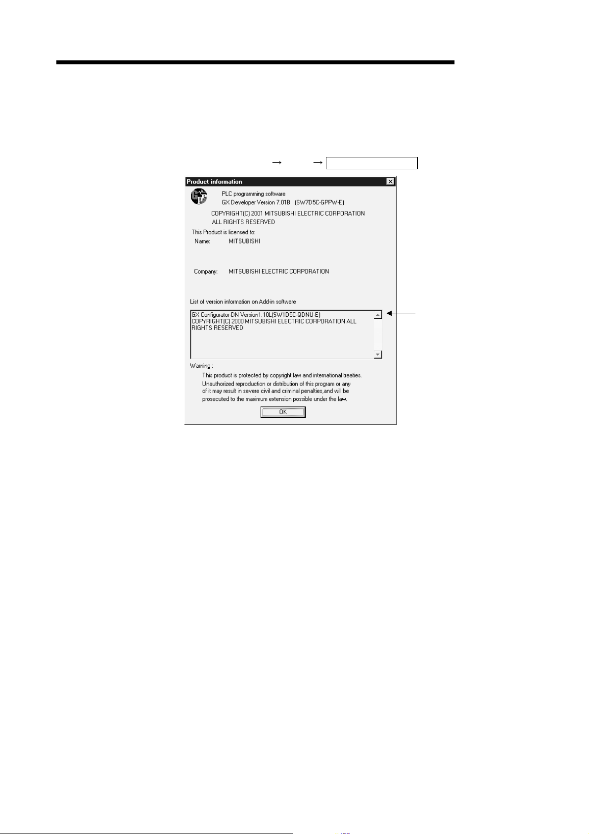
2 SYSTEM CONFIGURATION
(2) How to check the GX Configuration-DN software ver si on
The GX Configurator-DN software version can be checked in GX Developer's
"Product information" screen.
[Startup procedure]
GX Developer "Help" Product information
MELSEC-Q
Software version
(In the case of GX Developer Version 7)
2.4 About Use of the QJ71DN91 with the Q00J/Q00/Q01C PU
Here, use of the QJ71DN91 with the Q00J/Q00/Q01CPU is explained.
(1) Number of QJ71DN91 that can be installed when the Q00J/Q00/
Q01CPU is used.
See item 2.2 concerning the number of QJ71DN91 that can be installed when the
Q00J/Q00/Q01CPU is used.
(2) Limitations when using the Q00J/Q00/Q01CPU
When using Q00J/Q00/Q01CPU, use QJ71DN91 which function version is B and
first 5 digits of the serial No. is 03052 or later.
2 - 5 2 - 5
Page 18

2 SYSTEM CONFIGURATION
2.5 About Additional Function
The added func ti on is de scribed below.
Function Serial No. Function Outline Reference Section
Addition of Each Node Communication
H
Error Status (addresses 01C0
/448 to 451)
to 01C3
First five digits of
H
serial No. are
04102 or later
Indicates whether an I/O
communication error has
occurred or not in each node.
POINT
Refer to Se ctio n 2 .3 fo r the w ay to con fi r m th e se ri al No .
2.6 Compatible DeviceNet Products from Other M anu facturers
It is assumed that most of the DeviceNet products on the market are compatible.
However, compatibility with the products of other manufacturers is not guaranteed.
MELSEC-Q
Section 3.4.1 (10)
2 - 6 2 - 6
Page 19
3 SPECIFICATIONS
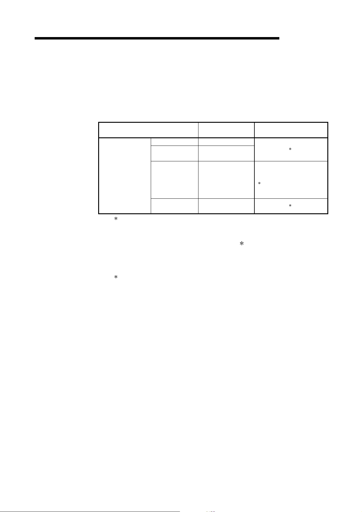
3 SPECIFICATIONS
3.1 Performance Specifications
This section explains the performance specifications for QJ71DN91, I/O signals for
PLC CPU and spe ci fi c atio n s fo r bu ffe r me mory.
See the PLC CPU User's Manual to be used for the general specifications for
QJ71DN91.
Item Specifications
Node type Device net master (Group 2 only client)
Node numbers which can be set 0 to 63
3
When
master
function
When slave
function
Communication specifications
Communications speed One speed can be selected from 125 kbps, 250 kbps and 500kbps.
Maximum cable length
Current consumption required on the network 0.03 A
Number of times to write flash ROM Max. 100000 times
No. of I/O occupied points 32 points (I/O allocation: Intelligent 32 points)
5 V DC internal current consumption 0.17 A
Weight 0.11 kg
: The maximum cable length complies with that in the device net specification (Release 2.0) Volumes 1 and 2.
Number of
connections
that be
created
Amount of
communication data
Node type Device net slaves (Group 2 server)
Setting possible node number 0 to 63
Number of
connections
that can be
created
Amount of
communication data
Message connection 63
I/O connection 63 (polling, bit strobe, change of state, cyclic)
I/O
communication
Message
communication
I/O connection
I/O
communication
Send Max. 4096 points (512 bytes), max. 256 bytes per 1 node
Receive Max. 4096 points (512 bytes), max. 256 bytes per 1 node
Send Max. 240 bytes
Receive Max. 240 bytes
1 (polling)
Send Max. 1024 points (128 bytes)
Receive Max. 1024 points (128 bytes)
Maximum transmitting distance of
Communic
ations
speed
125 kbaud 500 m 156 m
250 kbaud 250 m 78 m
500 kbaud 100 m
Thick
Cables
trunk line
Cables
100 m See 3.1.1 6 m
Thin
Thick and
thin cables
coexist
MELSEC-Q
Length of drop line
Maximum Total
39 m
3.1.1 Maximum transmitting distance w hen thi ck and thin cabl es coexist
The table below lists both the maximum transmitting distance when thick and thin
cables coexist.
Communication speed
125 kbaud Thick cable length + 5 Thin Cable length < 500 m
250 kbaud Thick cable length +2.5 Thin cable length < 250 m
500 kbaud Thick cable length + Thin cable length < 100 m
3 - 1 3 - 1
Maximum transmitting distance of trunk line w hen thick
and thin cables coexist
Page 20
3 SPECIFICATIONS
3.2 Functions
This section explains the functions of the QJ71DN91.
3.2.1 Master function (I/O communication function)
The I/O communication function executes the I/O data communication with each slave
node.
In the I/O communication function, the connection type can be set according to the
specification of the slave node.
There are four connection types: polling, bit strobe, change-of-state, and cyclic. The
connection type can be set with a parameter.
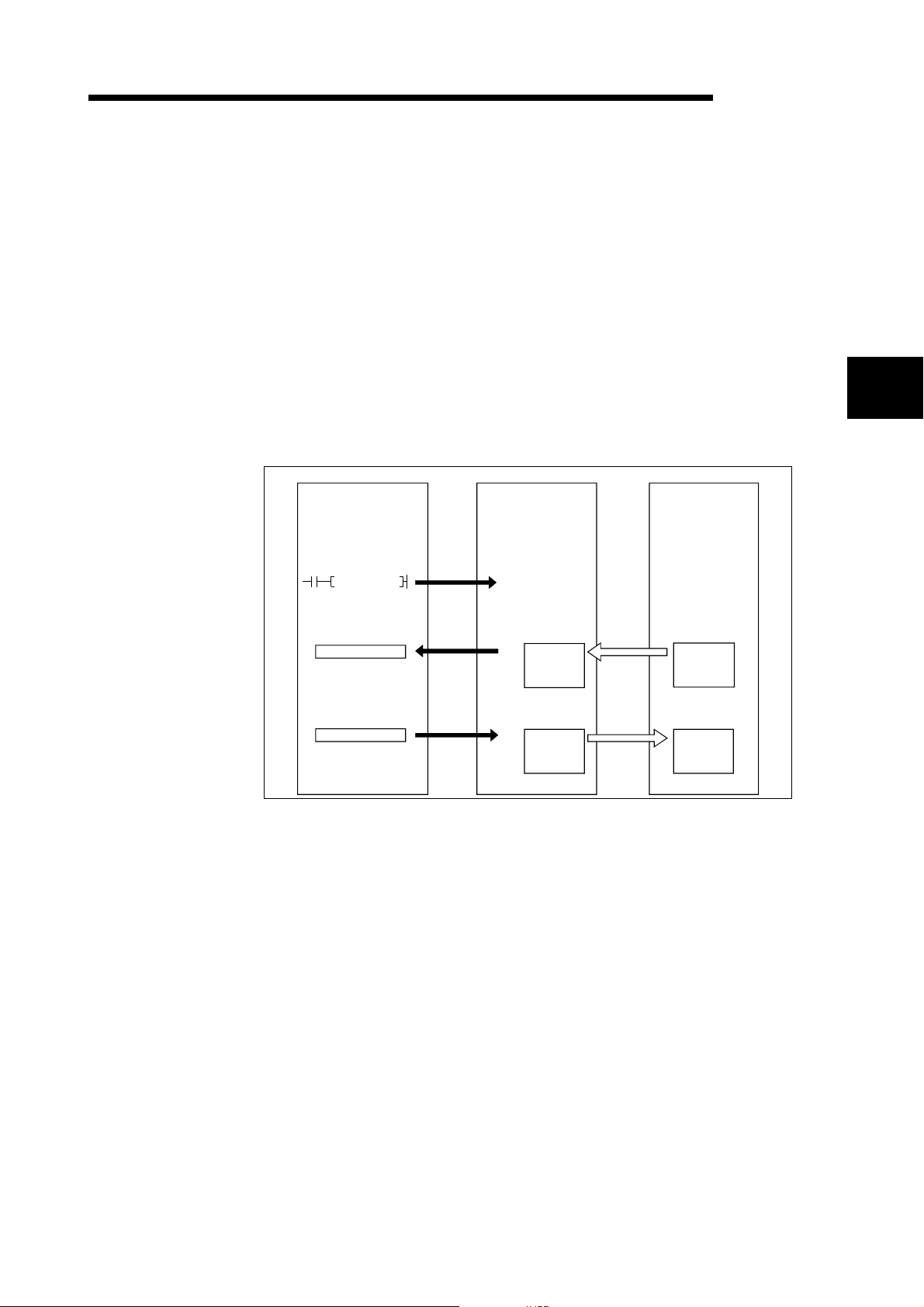
(1) When GX Configurator-DN is used
The following explains the I/O communication function when the GX
Configurator-DN is used.
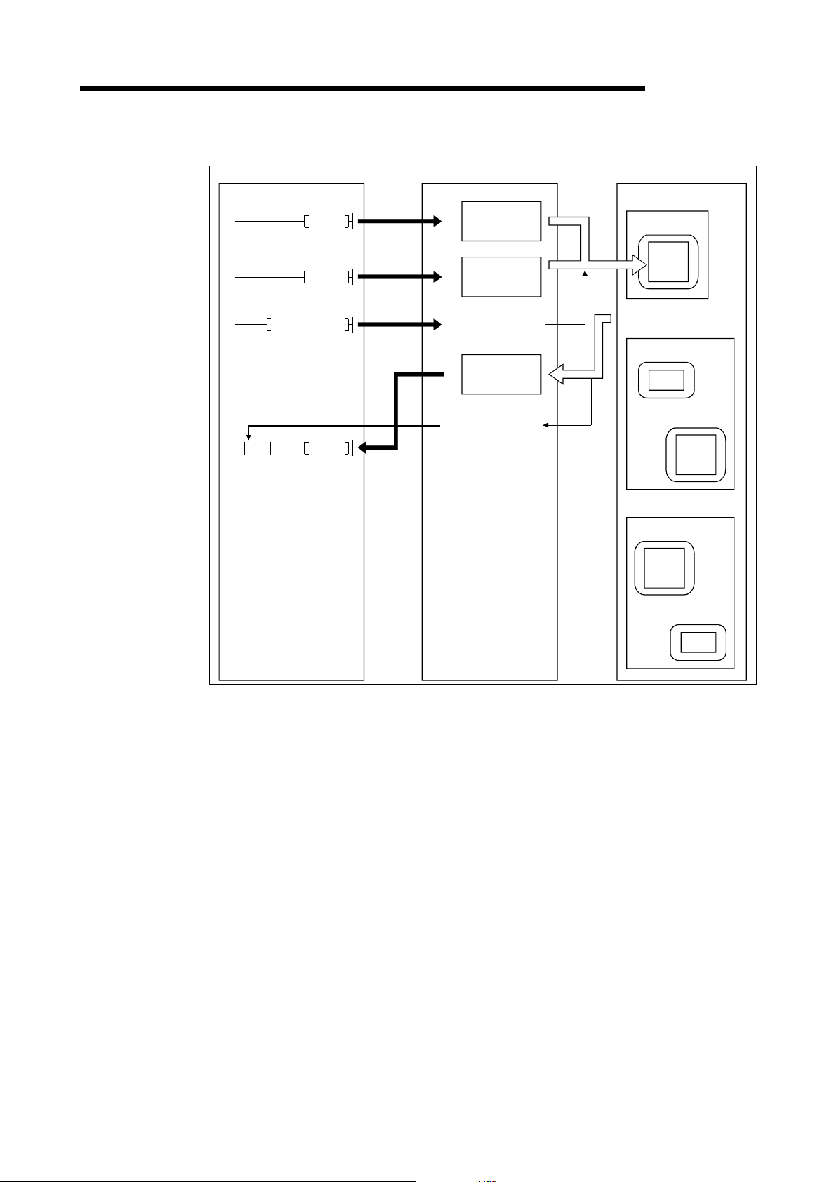
PLC CPU QJ71DN91 Slave node
MELSEC-Q
3
SET Y11
X
Y
1)
3)
4)
I/O communication
request
0700
H
Master function
receive
data area
07FF
H
0900
H
Master function
transmit
data area
09FF
H
2)
Transmission
5)
Reception
[I/O communication]
1) When the I/O communication request (Y11) is set, the I/O
communication with each slave node starts. It is not ne cessary to set
Y11, however, when the auto communication start is set with a
parameter.
[Reception data]
2) The input status from each slave node is automatically stored in the
"master function reception data" area of the buffer memory in the
QJ71DN91.
3) The input status stored in the "master function reception data" area of
the buffer me mory is loaded onto th e PL C CP U by th e a uto r e fr e sh
setting.
[Transmission data]
4) The ON/OFF information to be sent to the slave node is written into the
"master function transmission data" area of the buffer memory by the
auto refresh setting.
5) The ON/OFF information stored in the "master function transmission
data" area i s aut o mati cal ly sent to a slav e no de .
3 - 2 3 - 2
Page 21
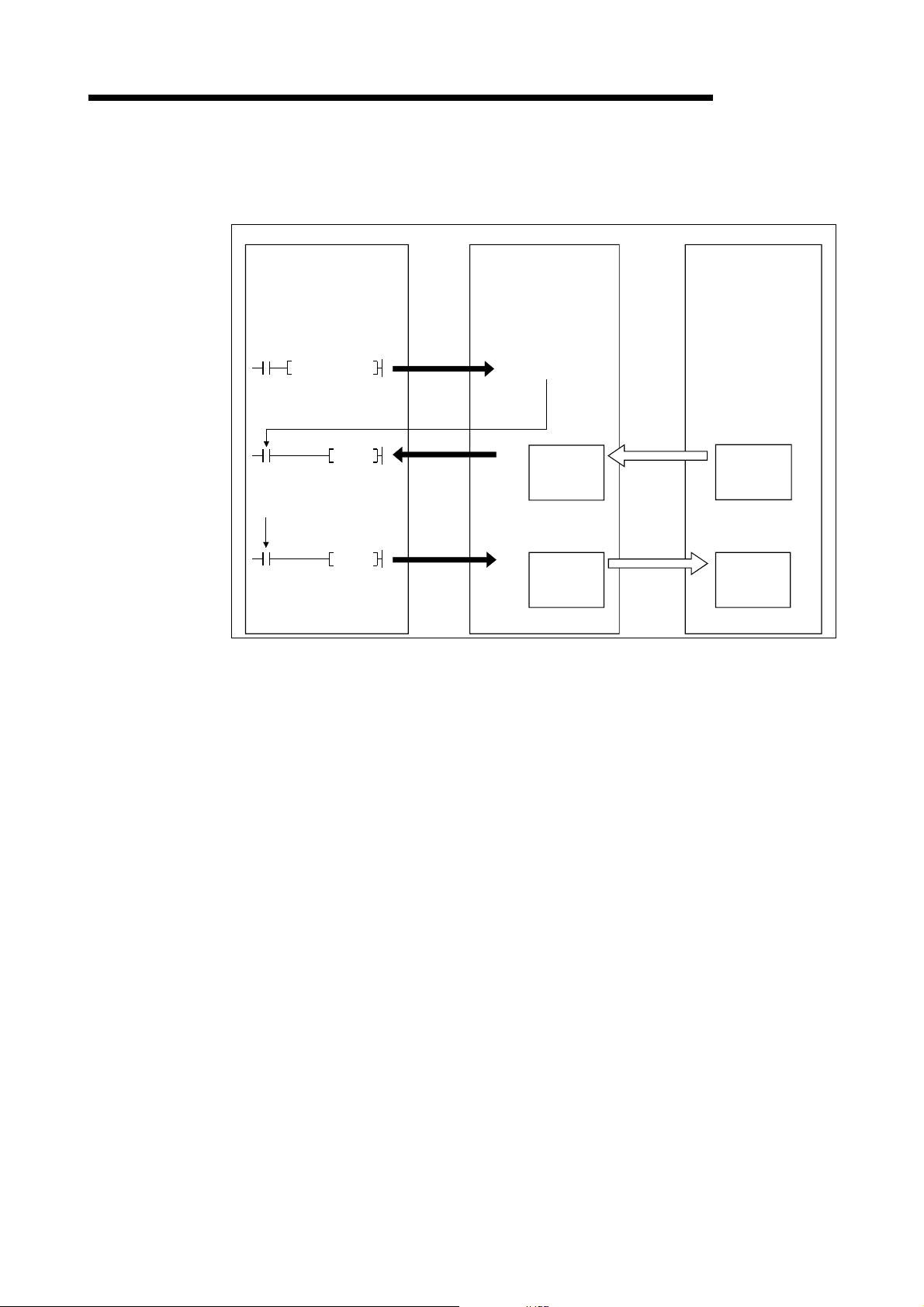
3 SPECIFICATIONS
(2) When the sequence program is used
MELSEC-Q
The following explains the I/O communication function when the sequence
program is used.
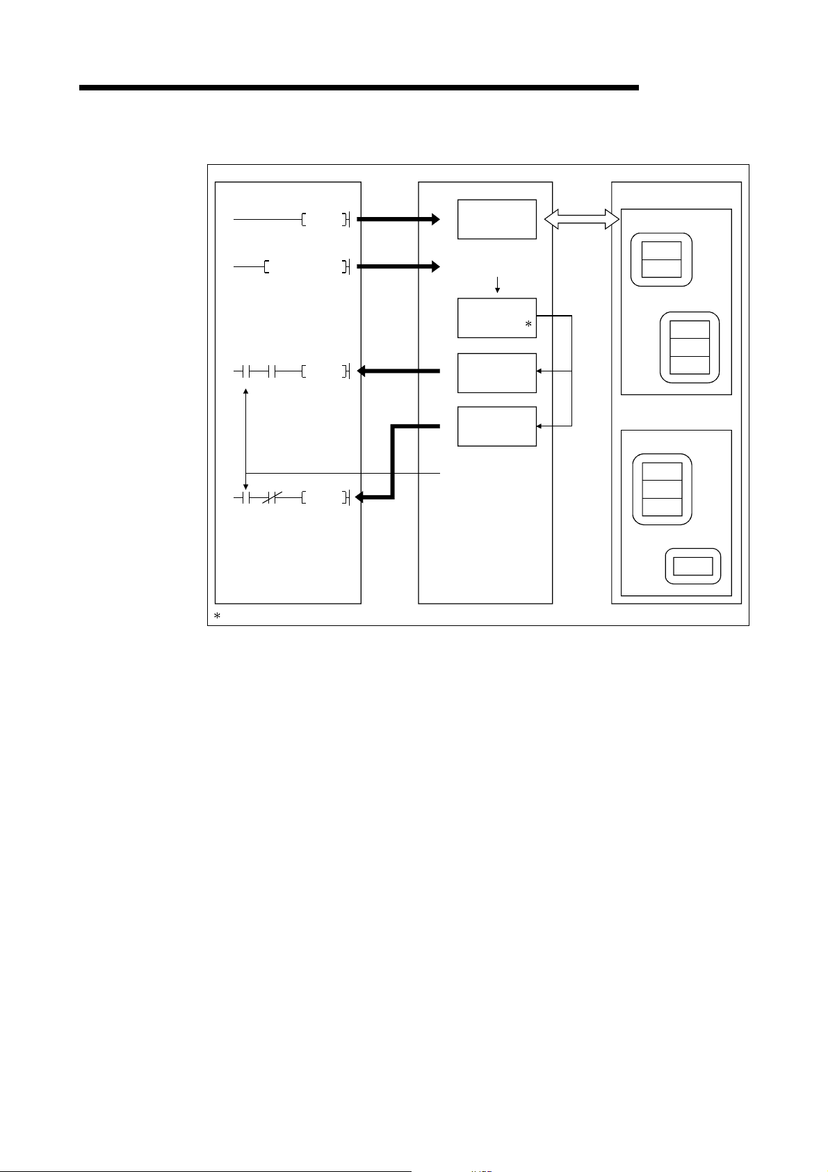
PLC CPU QJ71DN91 Slave node
SET Y11
FROM
X01
I/O communication
in progress
TO
X01
I/O communicating
[I/O communication]
1) When the I/O communication request (Y11) is set, the I/O
[Reception data]
2) The input status from each slave node is automatically stored in the
3) The input status stored in the "master function receive data" area of the
1)
3)
4)
I/O communication
request
H
0700
Master function
receive
data area
H
07FF
H
0900
Master function
transmit
data area
H
09FF
2)
Transmission
3)
Reception
communication with each slave node starts. It is not ne cessary to set
Y11, however, when the auto communication start is set with a
parameter.
"master function receive data" area of the buffer memory in the
QJ71DN91.
buffer memory is loaded onto the PLC CPU by the FROM instruction of
the sequence program.
[Transmission data]
4) The ON/OFF information to be sent to the slave node is written into the
"master function transmit data" area of the buffer memory by the TO
instruction of the sequence program.
5) The ON/OFF information stored in the "master function transmit data"
area is auto mati cal ly sent to the slave node.
3 - 3 3 - 3
Page 22
3 SPECIFICATIONS
(3) Overview of each connection type
MELSEC-Q
The following explains an overview of each connection type used during the I/O
communication.
(a) Polling
As shown in the following diagram, the communication method by which
the communication with each slave node is repeated, as described from 1)
to 6), is the polling communication. The connection that uses this
communication is the polling connection.
1) The master node tr a ns mit s th e ou tp u t da ta .
2) The slave node transmits input data by setting 1) to trigger.
3) The master node tr a ns mit s th e ou tp u t da ta .
4) The slave node transmits input data by setting 3) to trigger.
5) The master node tr a ns mit s th e ou tp u t da ta .
6) The slave node transmits input data by setting 5) to trigger.
Master node
1)
4)
3)
2)
Slave node
6)
5)
3 - 4 3 - 4
Page 23
3 SPECIFICATIONS
MELSEC-Q
(b) Bit strobe
As shown in the following diagram, the communication method by which
the communication with each slave node is repeated, as described from 1)
to 4), is the bit strobe communication. The connection that uses this
communication is th e bit st robe co nne c ti on .
1) Output information of a maximum of one bit is transmitted
simultaneously to each slave node.
2) The slave node transmits the input data by setting the transmission of
1) to trigger.
3) The slave node transmits the input data by setting the transmission of
1) to trigger.
4) The slave node transmits the input data by setting the transmission of
1) to trigger.
Master node
4)
2)
3)1)
Slave node
3 - 5 3 - 5
Page 24
3 SPECIFICATIONS
MELSEC-Q
(c) Change-of-state
As shown in the following diagram, the communication method that
executes the communication of [1] and [2] as the I/O data changes is the
change-of-state communication, and the connection that uses this
communication is the change-of-state connection.
No data transmission is performed unless the I/O data is changed.
1) When the output data of the master node changes, the data is sent to
the slave node.
2) When the input data of the slave node changes, the data is sent to the
master node.
There is no concept of the network scan in the change-of-state
communication.
Master node
1) 2)
Slave node
3 - 6 3 - 6
Page 25
3 SPECIFICATIONS
MELSEC-Q
(d) Cyclic
As shown in the following diagram, the communication method that
regularly repeats the communication of [1] and [2] is the cyclic
communication, and the connection that uses this communication is the
cyclic connection .
1) The data of the master node is sent to the slave node.
2) The data of the slave node is sent to the master node.
The cycle of the cyclic communication can be specified for each slave
node.
Specify the cycle of the cyclic communication in the following parameter
items:
Transmission cycle from master node: Production inhibit time
Transmission cycle from slave node: Expected packet rate
There is no concept of the network scan in the cyclic communication.
Master node
1) 2)
Slave node
3 - 7 3 - 7
Page 26
3 SPECIFICATIONS
3.2.2 Master function (Message communication function)
The message communication function is used to get and set the attribute data of a
slave node.
(1) Getting attributes
PLC CPU QJ71DN91 Slave node (MAC ID)
0110
TO
SET Y12
FROM
X05
X02
FROM
X05
X02
Message communication
completion
1)
2)
6)
5)
H
Message
communication
command area
H
011F
Message
communication
request
H
0120
Message
communication
result area
H
012F
H
0130
Message
communication
data area
H
01A7
4)
Message
communication
complete
MELSEC-Q
Class
2)
Instance
Attribute
Attribute
Instance
Attribute
3)
Class
Instance
Attribute
Instance
Attribute
Attribute
Attribute
: In DeviceNet, the area used for reading and writing via communication
is specified by the numbers representing the class ID, instance ID, and
attribute ID. For details, refer to the manual of each slave node.
1) The TO instruction of the sequence program sets to get attributes in the
"message communication command" area of the buffer memory.
2) When the message communication request (Y12) is turned ON by the
sequence program, the data, which is set in the "message
communication command" area in the buffer memory, is sent to the
slave node and the message communication starts.
3) When the QJ71DN91 receives data from the slave node, it is processed
as follows:
• The specific data of the slave node that is set in the "message
communication command" area is stored in the "message
communication data" area of the buffer memory.
• The processing result of message communication is stored in the
"message communication result" area of the buffer memory.
4) The message communication is completed when the processing result
is stored in the "message communication result" area of the buffer
memory, and the message communication completion (X02) is
automatically turned ON.
5) Upon normal compl et io n, th e da ta in the sl av e no de , which i s st ore d in
the "message communication data" area of the buffer memory, is
loaded onto the PLC CPU by the FROM instruction of the sequence
program.
6) If the message communication error signal (X05) is turned ON, the
FROM instruction reads the contents of the "message communication
result" area, and the cause of the error is verified.
3 - 8 3 - 8
Page 27
3 SPECIFICATIONS
(2) Setting attributes
MELSEC-Q
PLC CPU QJ71DN91 Slave node (MAC ID)
H
SET Y12
Next
X05
processing
X02
Message
communication
completion
TO
TO
0110
1)
011F
0130
2)
01A7
3)
0120
012F
5)
6)
Message
communication
command area
H
H
Message
communication
data area
H
Message
communication
request
H
Message
communication
result area
H
Message
communication
complete
3)
4)
Class
Instance
Attribute
Attribute
Class
Instance
Attribute
Instance
Class
Attribute
Attribute
Instance
Attribute
Attribute
Instance
Attribute
1) The TO instruction of the sequence program sets to set attributes in the
"message communication command" area of the buffer memory.
2) The TO instruction of the sequence program writes the data to be
written in the "message communication data" area of the buffer
memory.
3) When the message communication request (Y12) is turned ON, the
data, which is stored in the "message communication data" area of the
buffer memory, is written to the slave node in the area specified by the
"message communication command."
4) When the write process is finished, the message communication result
is stored in the "message communication result" area of the buffer
memory.
5) The message communication is completed when the processing result
is stored in the "message communication result" area of the buffer
memory, and the message communication completion (X02) is
automatically turned ON.
6) If the message communication error signal (X05) is turned ON, the
FROM instruction reads the contents of the "message communication
result" area, and the cause of the error is verified.
3 - 9 3 - 9
Page 28
3 SPECIFICATIONS
(3) Reading the communication err or i nformation
MELSEC-Q
PLC CPU QJ71DN91 Slave node (MAC ID)
I/O
Class 1
Instance
Attribute
Attribute
TO
SET Y12
H
1)
2)
0110
011F
Message
communication
command area
H
Message
communication
request
communication
Slave
information
storage area
H
0120
X02
X05
X05
X02
Message communication
completion
The status of each slave station is stored during I/O communication.
FROM
FROM
5)
012F
0130
01A7
3)
4)
Message
communication
result area
H
H
Message
communication
data area
H
Message
communication
complete
1) The TO instruction of the sequence program sets to read the
communication error information in the "message communication
command" area of the buffer memory.
2) When the message communication request (Y12) is turned ON by the
sequence program, the error information of the applicable slave node
that has been accumulated in the QJ71DN91 is read and processed as
follows:
• The error information of the slave node that was set by the "message
communication command" area is stored in the "message
communication data" area of the buffer memory.
• The processing result of the message communication is stored in the
"message communication result" area of the buffer memory.
3) When the processing result is stored in the "message communication
result" area of the buffer memory, the message communication
completion ( X02 ) is au tomat i cal ly turned ON.
4) The communication error information of the slave node, which is stored
in the "message communication data" area of the buffer memory, is
loaded onto the PLC CPU by the FROM instruction of the sequence
program.
5) If the message communication error signal (X05) is turned ON, the
FROM instruction reads the contents of the "message communication
result" area, and the cause of the error is verified.
2)
Instance
Attribute
Attribute
Attribute
Class
Instance
Attribute
Attribute
Attribute
Instance
Attribute
3 - 10 3 - 10
Page 29
3 SPECIFICATIONS
3.2.3 Slave function (I/O communication function)
The I/O communication function executes the communication of the I/O data with the
master node using the polling method.
(1) When GX Configurator-DN is used
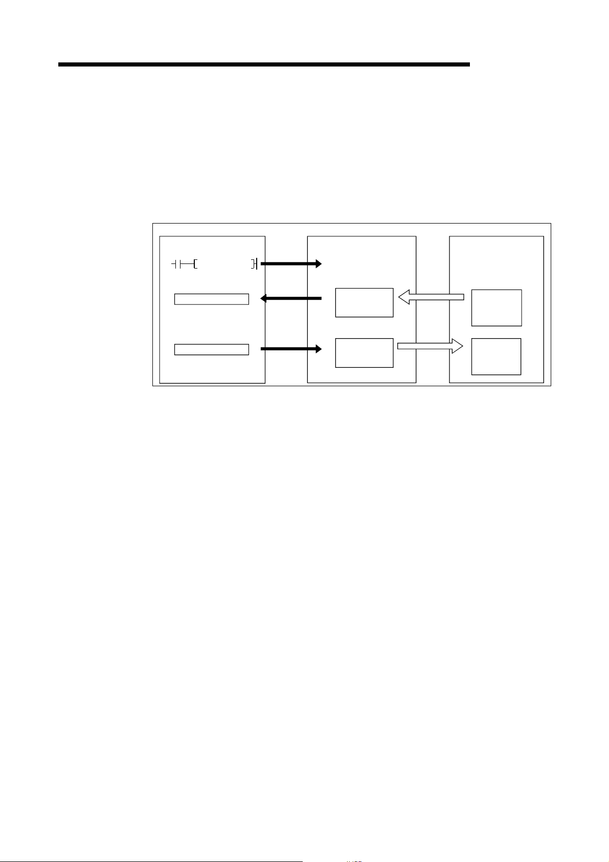
The following explains the I/O communication function when the GX
Configurator-DN is used.
PLC CPU QJ71DN91 Master node
MELSEC-Q
SET Y11
X
Y
1)
3)
4)
I/O communication
request
H
0B00
Slave function
H
0B3F
H
0C00
Slave function
H
0C3F
receive
data area
transmit
data area
2)
Transmission
5)
Reception
[I/O communication]
1) Communication with the master node starts when the I/O
communication request (Y11) is turned ON.
[Reception data]
2) Transmission data from the master node is automatically stored in the
"slave func ti on re ce ive da ta" ar ea o f th e bu ffe r me mory in the
QJ71DN91.
3) Transmission data from the mater node, which is stored in the "slave
function receive data" area of the buffer memory, is loaded onto the
PLC CPU by the auto refresh setting.
[Transmission data]
4) With the auto refresh setting, the ON/OFF information to be sent to the
master node is written in the "slave function transmit data" area of the
buff er memory.
5) The ON/OFF information, which is stored in the "slave function transmit
data" area of the buffer memory, is automatically sent to the master
node.
3 - 11 3 - 11
Page 30
3 SPECIFICATIONS
(2) When the sequence program is used
MELSEC-Q
The following explains the I/O communication function when the sequence
program is used.
PLC CPU QJ71DN91 Master node
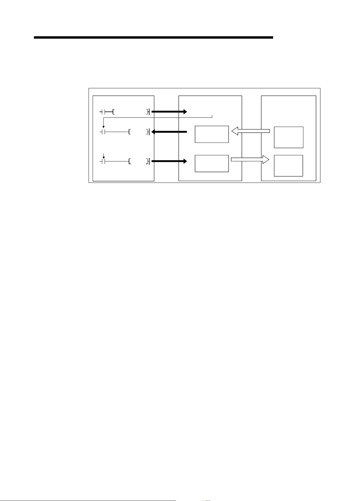
SET Y11
FROM
X01
I/O communicating
TO
X01
I/O communicating
[I/O communication]
1) Communication with the master node starts when the I/O
communication request (Y11) is turned ON.
[Reception data]
2) Transmission data from the master node is automatically stored in the
"slave func ti on re ce ive da ta" ar ea o f th e bu ffe r me mory in the
QJ71DN91.
3) The transmission data from the master node, which is stored in the
"slave functi on r e ceive da ta" area o f th e bu ffe r memory, is loaded onto
the PLC CPU by the FROM instruction of the sequence program.
1)
3)
4)
I/O communication
request
H
0B00
Slave function
data area
H
0B3F
H
0C00
Slave function
data area
H
0C3F
receive
transmit
2)
Transmission
5)
Reception
[Transmission data]
4) The TO instruction of the sequence program writes the ON/OFF
information to be sent to the master node in the "slave function transmit
data" area of the buffer memory.
5) The ON/OFF information, which is stored in the "slave function transmit
data" area of the buffer memory, is automatically sent to the master
node.
3 - 12 3 - 12
Page 31

3 SPECIFICATIONS
3.3 I/O Signals for the PLC CPU
This section explains the input/output signals for the PLC CPU of the QJ71DN91.
3.3.1 I/O signal list
The I/O signal list fo r the QJ71 DN91 is shown in Ta ble 3 .2.
The I/O numbers (X/Y) and I/O addresses described from this chapter are applicable
when the QJ71DN91 is installed in slot 0 of the basic base module.
MELSEC-Q
Table 3.2 I/O signal list
QJ71DN91 PLC CPU PLC CPU QJ71DN91
Input number Signal name
X00 Watchdog Timer Error Y00
X01 I/O Communicating Y01
X02
X03 Maste r Fun c tion Fo r Error Se t Sig na l —Y03
X04 Slave Down Signal —Y04
X05
X06
X07
X08 Slave Function For Error Set Signal — Y08
X09 Use proh ib ite d — — Y09
X0A H/W Testing
X0B H/W Test Comp le tion
X0C H/W Test Error Detection
X0D Y0D
X0E
X0F Module Ready Y0F
X10 Y10
X11 Y11 I/O Commun icat ion Requ es t
X12 Y12 Message Communication Req u est —
X13
X14 Auto Configuration Executing — Y14 Use prohibite d — —
X15 Au to Co n f ig u r at io n C o mp le t io n — Y15 Auto Conf igur at io n Requ es t —
X16 Y16 Use prohib ite d — —
X17 Y17
X18 Y18
X19 Y19
X1A Y1A
X1B Y1B
X1C Y1C
X1D Y1D
X1E Y1E
X1F
Message Communication
Completion
Message Communication Error
Signal
Saving Parameter To The Flash
ROM
Save Parameter To Flas h ROM
Completion
Use prohibite d — —
Use prohibite d — —
Use prohibite d — —
Usability Usability
Master
function
At the time of the
hardware test
At the time of the
hardware test
At the time of the
hardware test
Slave
function
Output number Signal name
—Y02
—Y05
Y06
Y07
Y0A
Y0B
Y0C
Y0E
Y13
Y1F
Use prohibite d — —
Master Function For Error Reset
Request
Save Parameter To Flas h ROM
Request
Slave Function For Error Reset
Request
Use prohibite d — —
Master
function
Slave
function
—
—
IMPORTANT
The use-prohibited output signals shown in Table 3.2 are accessed by the system
and cannot be accessed by the user. In the event these signals are used (turned
ON/OFF) by the user, normal operations cannot be guaranteed.
3 - 13 3 - 13
Page 32

3 SPECIFICATIONS
W
3.3.2 Details of the I/O signals
The following describes the ON/OFF timings and conditions of the I/O signals.
(1) Watchdog Timer Error: X00
This is turned ON when an error occurs in the QJ71DN91.
OFF: Module normal
ON: Module error
atchdog timer error (X00)
Module ready (X0F)
(2) I/O Communicating: X01, I/O Communication Request: Y11 (w hen
the master function is used)
This signal is used to start the I/O communication of the master function with the
parameters set by the "parameters for the master function" of the buffer memory.
Use this signal while the module ready (X0F) is ON.
MELSEC-Q
(a) When the auto start is not set:
1) Verify that the auto configuration request (Y15) and the save parameter
to flash ROM request (Y17) are OFF.
2) To start the I/O communication, use the sequence program to turn ON
the I/O communication request (Y11).
3) When the I/O communication request (Y11) is turned ON, the
parameter check is executed. If the parameter check is successful, the
I/O communication starts and the I/O Communicating (X01) is turned
ON. If the par a met e r ch e ck fails, the master fun ction for error set sign al
(X03) is turned ON and the ERR. LED is lit. Check the contents of the
error with the "error information for the master function" of the buffer
memory address 1B1
H
.
4) To stop the I/O communication, use the sequence program to turn OFF
the I/O communication request (Y11).
5) I/O communication stops and the I/O communicating (X01) is turned
OFF.
When the parameter check is successful
Module Ready (X0F)
I/O Communication Request (Y11)
I/O Communicating (X01)
Parameter
check
When the parameter check fails
Module Ready (X0F)
I/O Communication Request (Y11)
I/O Communicating
Master Function For Error Set Signal
Parameter
check
3 - 14 3 - 14
Page 33

3 SPECIFICATIONS
MELSEC-Q
(b) When the auto start is set
1) The module re ady ( X0 F) i s tu rn ed ON when th e power is turned ON,
and the parameter check is executed automatically.
2) If the parameter check is successful, the I/O communication starts and
the I/O communicating (X01) is turned ON. If the parameter check fails,
the master function for error set signal (X03) is turned ON and the ERR.
LED is lit. Check the contents of the error with the "master function for
error information" of the buffer memory address 1B1
POINT
To stop the I/O communication, set Y11, then reset after 200 ms or longer.
When the parameter check is successful:
H
.
Module Ready (X0F)
I/O Communicating (X01)
When the parameter check fails:
Module Ready (X0F)
I/O Communicating (X01)
Master Function For Error
Set Signal (X03)
Parameter
check
Parameter
check
3 - 15 3 - 15
Page 34

3 SPECIFICATIONS
(3) I/O Communicating : X01, I/O Communication Request: Y11 (w hen
MELSEC-Q
the slave function is used)
These signals are used to start the I/O communication of the slave function with
the number of I/O points that is set by the "setting area of the number of slave
function reception bytes" and the "setting area of the number of slave function
transmission bytes" of the buffer memory.
Use these signals while the module ready (X0F) is ON.
(a) To start the I/O communication, use the sequence program to turn ON the
I/O communication request (Y11).
(b) When the I/O communication request (Y11) is turned ON, the parameter
check is executed. If the parameter check is successful, the I/O
communication starts and the I/O communicating (X01) is turned ON. If the
parameter check fails, the slave function for error set signal (X08) is turned
ON and the ERR. LED is lit. Check the contents of the error with the "error
information for the slave function" of the buffer memory address 601
H
.
(c) To stop the I/O communication, use the sequence program to turn OFF the
I/O communication request (Y11).
(d) The I/O communication stops and the I/O communicating (X01) is turned
OFF.
When the parameter check is successful:
Module Ready (X0F)
I/O Communication
Request (Y11)
I/O Communicating (X01)
Parameter
check
When the parameter check fails:
Module Ready (X0F)
I/O Communication Request
(Y11)
I/O communicating (X01)
Slave Function For Error Set
Signal (X08)
Parameter
check
3 - 16 3 - 16
Page 35

3 SPECIFICATIONS
(4) Message Communication Completion: X02, M essag e
MELSEC-Q
Communication Error Signal: X05, M essag e C ommuni cation
Request: Y12
These signals are used to execute the message communication. Message
communication can be executed when the "master function communication
status" area of the buffer memory is "in operation (C0
POINT
When making message communication, set the master function parameters.
If the master function parameters have not been set, a message connection is
opened using message group 1.
(a) The procedure for executing the message communication is as follows:
1) Write the message communication data into the "message
communication co mman d" area o f th e bu ffe r me mory.
2) Use the sequence program to turn ON the message communication
request (Y12).
(Set an interv al of 10 0 ms or l on ge r befo r e tu rni ng ON th e messa ge
communication request.)
H
)" or "st op (40H)".
Message Communication
Request (Y12)
Message Communication
Completion (X02)
Message Communication
Error Signal (X05)
FROM/TO
(b) The message communication is completed. The communication result is
written into the "message communication result" area, and the message
communication completion (X02) is turned ON.
(c) Check the message communication result with the message communication
error signal (X05).
(d) After reading the communication data by the FROM instruction, use the
sequence program to turn OFF the message communication request (Y12).
The message communication completion (X02) and the message
communication error signal (X05) are automatically turned OFF.
With an error
No error
Write command
for the message
communication
(TO instruction)
Write data for
the message
communication
(TO instruction)
(During data transmission only)
Read result for
the message
communication
(FROM instruction)
Read data for
the message
communication
(FROM instruction)
(During data reception only)
3 - 17 3 - 17
Page 36

3 SPECIFICATIONS
(5) Master Function For Error Set Signal: X03, Master Function For
MELSEC-Q
Error Reset Request: Y13
These signals are used to indicate an error while executing the master function
and to reset the error code.
(a) When an error occurs via the master function, the error information is stored
in the "error information for the master function" area of the buffer memory
and the master function for error set signal (X03) is turned ON.
The master function for error set signal is automatically turned OFF when
the error cause is removed.
(b) After removing the error cause, use the sequence program to turn ON the
master function for error reset request (Y13), and the error code of the
"error-information for the master function" area is cleared.
Master Function For Error
Reset Request (Y13)
Master Function For Error
Set Signal (X03)
FROM/TO
Read error
information
(FROM instruction)
Error code
clear
(6) Slave Down Signal: X04
This signal indicates whether or not a slave node that is being stopped for
communication exists.
(a) This signal is turned ON when at least one slave node is being stopped
among the slave nodes that are set by the parameters.
OFF: Normal communi ca ti on wit h all no de s
ON: A communication-error node exists.
The slave node that is being sopped can be checked by referring to the
"each node's communication status" area in the addresses 01BC
H
01BF
of the buffer memory.
(b) X04 is automatically turned OFF when communication with the slave node
that is being sto pp ed re sumes.
H
to
3 - 18 3 - 18
Page 37

3 SPECIFICATIONS
(7) Saving Parameter To Flash ROM: X06, Save Parameter To Flash
MELSEC-Q
ROM Completion: X07, Save Parameter To Flash ROM R eq uest:
Y17 (when the master function is used)
These signals are used to save the "parameters for the master function" of the
buffer memory to the flash ROM in the QJ71DN91. Make a request to save
parameters to the flash ROM while the I/O communicating (X01) is OFF.
(a) Set the paramet e rs usi ng th e foll ow in g step s:
1) Write the parameters in the "parameters for the master function" area of
the buffer me mory.
2) Set the parameter save area selection bit.
3) Use the sequence program to turn ON the save parameter to flash
ROM request (Y17).
(b) When the request to save parameters to the flash ROM is accepted, and if the
parameter check is successful, the parameters will be saved and the saving
parameter to the flash ROM (X06) will turn ON. If the parameter check fails,
the master function for error set signal (X03) will tu rn ON and the ERR. LED
will light. Check the contents of the error in the "error information for the
master function" of the buffer memory address 1B1
H
.
(c) When the saving parameters to the flash ROM is completed, the save
parameter to flash ROM completion (X07) signal is automatically turned ON.
Communications with other slave nodes are stopped while the parameter is
being set.
By turning OFF the request to save parameters to the flash ROM, the saving
parameter to the flash ROM complete is automatically turned OFF.
When the parameter check is successful
I/O Communication
Request (Y11)
I/O Communicating (X01)
Save Paramter To Flash
ROM Request (Y 17)
Saving Parameter To
Flash ROM (X06)
Save Parameters To
Flash ROM Comple tio n (X 07)
TO instruction
When the parameter check fails
I/O Communication
Request (Y11)
I/O Communicating (X01)
Parameter
check
Write
parameter
data
Save Parameter To Flash
ROM Request (Y17)
Saving Parame te r To
Flash ROM (X06)
Save Parameter To Flash
ROM Completion (X07)
Master Function For Err or
Set Signal (X03)
TO instruction
Write
parameter
data
Parameter
check
3 - 19 3 - 19
Page 38

3 SPECIFICATIONS
(8) Saving Parameter To Flash ROM: X06, Save Parameter To Flash
MELSEC-Q
POINT
(1) Even if the save parameter to flash ROM request (Y17) is turned ON while the
I/O communicating (X01) is ON, save parameter to flash ROM completion
(X07) is not turned ON. Turn OFF the I/O communication request (Y11), then
after confirming that the I/O communicating (X01) is OFF, turn ON the save
parameter to flash ROM request (Y17) from the OFF state.
(2) Even if the I/O communication request (Y11) is turned ON while the save
parameter to flash ROM request (Y17) is ON, the I/O communicating (X01) is
not turned ON. Turn OFF the save parameter to flash ROM request (Y17), then
turn OFF the I/O communication request (Y11) once and turn it back ON again.
ROM Completion: X07, Save Parameter To Flash ROM R eq uest:
Y17 (when the slave function is used)
These signals are used when saving the "setting area for the number of slave
function input points" and "setting area for the number of slave function output
points" of the buffer memory to the flash ROM in the QJ71DN91. Make a request
to save parameters to the flash ROM while the I/O communicating (X01) is OFF.
(a) Set the paramet e rs usi ng th e foll ow in g step s:
1) Write the parameter in the "setting area of the number of slave function
reception bytes" and the "setting area of the number of slave function
transmission bytes" of the buffer memory.
2) Set the parameter save area selection bit.
3) Use the sequence program to turn ON the save parameter to flash
ROM request (Y17).
(b) When the request to save parameters to the flash ROM is accepted, and if
the number of I/O points check is successful, the number of I/O points
setting will be saved and the save parameter to flash ROM (X06) will turn
ON. If the number of I/O points check fails, the slave function for error set
signal (X08) is turned ON and the ERR. LED is lit. Check the contents of the
error in the "error information for the slave function" of the buffer memory
address 601
(c) When the number of I/O points setting is saved in the flash ROM, the save
parameter to flash ROM completion (X07) is automatically turned ON.
Communication with the master node is stopped while the number of I/O
points setting i s bein g sav ed .
By turning OFF the request to save parameters to the flash ROM, the saving
parameters to the flash ROM complete is automatically turned OFF.
When the parameter check is successful
I/O Communication
Request (Y11)
I/O Communicating (X01)
Save Paramter To Flash
ROM Request (Y17)
Saving Parameter To
Flash ROM (X06)
Save Parameter To Flas h
ROM Completion (X07)
H
.
Parameter
check
Write
TO instruction
parameter
data
3 - 20 3 - 20
Page 39

3 SPECIFICATIONS
I/O Communication
Request (Y11)
I/O Communicating (X01)
Save Parameter To Flash
ROM request (Y17)
Saving Parameter To
Flash ROM (X06)
Save Parameter To Flash
ROM Completion (X07)
Master Function For Error
Set Signal (X03)
TO instruction
MELSEC-Q
When the parameter check fails:
Parameter
check
Write
parameter
data
POINT
(1) Even if the save parameter to flash ROM request (Y17) is turned ON while the
I/O communicating (X01) is ON, save parameter to flash ROM completion
(X07) is not turned ON. Turn OFF the I/O communication request (Y11), then
after confirming that the I/O communicating (X01) is OFF, turn ON the save
parameter to flash ROM request (Y17) again from the OFF state.
(2) Even if the I/O communication request (Y11) is turned ON while the save
parameter to flash ROM request (Y17) is ON, the I/O communicating (X01) is
not turned ON. Turn OFF the save parameter to flash ROM request (Y17), then
turn OFF the I/O communication request (Y11) once and turn it back ON again.
3 - 21 3 - 21
Page 40

3 SPECIFICATIONS
(9) Slave Function For Error Set Signal : X08, Slav e Function For Err or
MELSEC-Q
Reset Request: Y18
These signals notify an error occurrence during execution of the slave function
and are used to reset the error code.
(a) When an error occurs by the slave function, the error information is stored in
the "error information for the slave function" area of the buffer memory, and
the slave function for error set signal (X08) is turned ON.
The slave function for error set signal is automatically turned OFF when the
error cause is removed.
(b) After removing the error cause, use the sequence program to turn ON the
slave function for error reset request (Y18). The error code of the "error
information for the slave function" area will be cleared.
Slave Function For Error Reset
Request (Y18)
Slave Function For Error Set
Signal (X08)
Error code
clear
Read error
FROM instruction
information
(FROM instruction )
(10) H/W Testing: X0A, H/W Test Completion: X0B, H/W Test Error
Detection: X0C
These signals indicate the status when the QJ71DN91 is set to the hardware test
mode (mode 9).
(a) When the mode switch is set to 9 and the power is turned ON, the H/W
testing (X0A) is turned ON.
(b) When the hardware test is completed normally, the H/W test completion
(X0B) signal will be turned ON. If an error occurs, the H/W test completion
(X0B) signal will not be turned ON but the H/W test error detection (X0C) will
be turned ON.
(11) Module Ready: X0F
This signal indicates whether the module is ready to operate.
When the module reaches ready-to-operate status, this signal is turned ON
automatically.
The module ready (X0F) is turned OFF when the watchdog timer error (X00) is
turned ON.
3 - 22 3 - 22
Page 41

3 SPECIFICATIONS
(12) Auto Configuration Executing: X14, Auto Configuration Completion:
MELSEC-Q
X15, Auto Configuration Request: Y 15
These signals are used in order to search the slave nodes that are connected to
the network and create parameters automatically. Execute the auto configuration
request while the I/O communicating (X01) is OFF.
(a) Verify that the DeviceNet device power and the network power are turned
ON.
(b) To execute the auto configuration, turn ON the auto configuration request
(Y15).
(c) The auto configuration starts and the auto configuration executing (X14) is
turned ON.
(d) When the auto configuration is completed, the auto configuration executing
(X14) is turned OFF and the parameters generated by auto configuration
processing is stored in the "parameters for the master function" area of the
buffer memory, and the auto configuration completion (X15) is turned ON.
I/O Communication
Request (Y11)
I/O Communicating (X01)
Auto Configuration Request (Y15)
Auto Configuration Executing (X14)
Auto Configuration Completion (X15)
POINT
(1) Confirm that the I/O communication request (Y11) is turned OFF. When Y11 is
turned OFF, not only the I/O communication of the master function, but also the
I/O communication of the slave function stops.
(2) The I/O communicating (X01) is not turned ON even if the I/O communication
request (Y11) is turned ON while the auto configuration request (Y15) is ON.
Turn OFF the auto configuration request (Y15), then turn OFF the I/O
communication request (Y11) once, then turn it back ON again.
(3) For the parameters created by auto configuration, be sure to verify that the
contents are correct.
3 - 23 3 - 23
Page 42

3 SPECIFICATIONS
3.4 Buffer Memory
The buffer memory transfers data between the QJ71DN91 and the PLC CPU.
The FROM and TO instructions of the PLC CPU are used to read and write the buffer
memory data in the QJ71DN91.
The contents of the buffer memory are reset to 0 when the power is turned OFF or
when the PLC CPU is reset.
However, the "parameter" area is initialized using the saved parameters if the
parameters have been saved in the flash ROM.
3.4.1 Buffer memory list
The buffer memory list is shown in Table 3.3.
MELSEC-Q
Table 3.3 Buffer memory list (1/2)
Address Usability
Hexadecimal Decimal
0000H to
010F
0110H to
011F
0120H to
012F
0130H to
01A7
01A8H to
01AF
01B0
01B1
01B2
01B3
01B4H to
01B7
01B8H to
01BB
01BCH to
01BF
01C0H to
01C3
01C4H to
01C7
01C8H to
01CB
01CCH to
01CF
01D0H to
01D3
01D4H to
03CF
03D0H to
03EF
03F0
03F1H to
04FF
0500H to
05FB
256 to 271 Use prohibite d — — — — —
H
272 to 287
H
288 to 303
H
304 to 423
H
424 to 431 Use prohibite d — — — — —
H
H
H
H
H
H
H
H
H
H
H
H
H
H
H
H
H
H
432
433
434 Bus Error Counter
435 Bus Off Counter
436 to 439
440 to 443 Use prohibite d — — — — —
444 to 447
448 to 451
452 to 455
456 to 459 Use prohibite d — — — — —
460 to 463
464 to 467 Use prohibite d — — — — —
468 to 975
976 to 1007 Use prohibited — — — — —
1008
1009 to 1279 Use prohibi te d — — — — —
1280 to 1531
Item Description
Message communication
command
Message communication
result
Message communication
data
Master Function
Communication Status
Master Function For Error
Information
Each Node Configuration
Status
Each Node
Communication Status
Each Node
Communication Erro r
Status
Each Node Obstacle
Status
Down Node Detection
Disable Statu s
Parameters for the master
function
Auto configuration
operation setting
Master Function For I/O
Address Area
Stores the request data for executing
the message communication.
Stores the re sult dat a of th e messa ge
communication.
Stores the transmission and reception
data of the message communication.
Stores the communication status of
the master function.
Higher byte: Erro r co de
Lower byte: Sto re s th e nod e nu mbe r
where the error occurred.
Stores the number of times errors are
detected in the communication data.
Stores the number of communication
errors.
Indicates whether or not each slave
node is set with a parameter.
Indicates whether or not each node is
executing I/O communication.
Indicates whether an I/O
communication error has occurred or
not in each node.
Indicates whether or not each node
has a trouble.
Sets whethe r or not the "slave down"
signal (X04) re fle cts the dow n stat u s
of each slave node.
Area for setting parameters for the
master function by the sequence
program.
Sets up the operation of the auto
configuratio n.
Displays the address and size of each
I/O data for the master function.
Master
function
Slave
function
Write from the
PLC CPU
allowed?
Reference
— Yes 3.4.2 (1)
— No 3.4.2 (2)
— Yes 3.4.2 (3)
— No 3.4.2 (4)
— No 3.4.2 (5)
— No 3.4.2 (6)
— No 3.4.2 (7)
— No 3.4.2 (8)
— No 3.4.2 (9)
— No 3.4.2 (10)
— No 3.4.2 (11)
— No 3.4.2 (12)
— Yes 3.4.2 (13)
— Yes 3.4.2 (14)
— No 3.4.2 (15)
section
3 - 24 3 - 24
Page 43

3 SPECIFICATIONS
MELSEC-Q
Table 3.3 Buffer memory list (2/2)
Address Usability
Hexadecimal Decimal
H
05FC
05FD
05FE
05FF
0600
0601
0602H to
060D
060E
060F
0610H to
061F
0620H to
0624
0625
0626
0627H to
062D
062E
062F
0630
0631
0632H to
06FF
0700H to
07FF
0800H to
08FF
0900H to
09FF
0A00H to
0AFF
0B00H to
0B3F
0B40H to
0BFF
0C00H to
0C3F
0C40H to
7FFF
H
H
H
H
H
H
H
H
H
H
H
H
H
H
H
H
H
H
H
H
H
H
H
H
H
H
1532 Present Link Scan Time
1533 Minimum Link Scan Time
1534 Maximum Link Scan Time
1535 Use prohibited — — — — —
1536
1537
1538 to 1549 Use prohibi te d — — — — —
1550
1551
1552 to 1567 Use prohibi te d — — — — —
1568 to 1572 Model Name Dis p lay “QJ71DN91” is set in ASCII co de . No 3.4.2 (22)
1573 Node number
1574 Mode Switch Number
1575 to 1581 Use prohibi te d — — — — —
1582
1583
1584
1585
1586 to 1791 Use prohibi te d — — — — —
1792 to 2047
2048 to 2303 Use prohibi te d — — — — —
2304 to 2559
2560 to 2815 Use prohibi te d — — — — —
2816 to 2879
2880 to 3071 Use prohibi te d — — — — —
3072 to 3135
3136 to
32767
Item Description
Slave Function
Communication Status
Slave Function For Error
Information
Setting area of the number
of slave funct ion re cep t io n
bytes
Setting area of the number
of slave function
transmission bytes
H/W Test Item Display
Area
H/W Test Result Storing
Area
Parameter save area
selection bit
Auto commun ica t ion st ar t
setting
Master Function Receive
Data
Master Function Transmit
Data
Slave Function Receive
Data
Slave Function Transmit
Data
Write from the
PLC CPU
allowed?
No 3.4.2 (19)
Displays the current link scan time
(module: ms).
Displays the minimum link scan time
(module: ms).
Displays the maximum link scan t ime
(module: ms).
Stores the communication status for
the slave function.
Master
function
—
Slave
function
— No 3.4.2 (16)
— No 3.4.2 (17)
— No 3.4.2 (18)
Stores the para mete r er ror s , et c. — No 3.4.2 (20)
Sets the number of reception bytes
for the slave function (reception from
— Yes 3.4.2 (21)
master).
Sets the number of tra ns mis s ion
bytes for the s lave fun c t ion
— Yes 3.4.2 (21)
(transmission to master).
Displays the node number currently in
operation.
Displays the mode swi tch numbe r
currently in operation.
Displays the item number of the
hardware test being executed.
Stores the result of the hardware test.
Selects area to save to the flash ROM
by the parameter-save request (Y17).
At the time of the
hardware test
At the time of the
hardware test
No 3.4.2 (23)
No 3.4.2 (24)
No 3.4.2 (25)
No 3.4.2 (26)
Yes 3.4.2 (27)
Selects whether or not to start the I/O
communicatio n au tomat i ca lly at
Yes 3.4.2 (28)
startup.
Stores the data received from each
slave node.
Stores the data to be sen t to eac h
slave node.
Stores the data received from the
master node.
Stores the data to be sen t to the
master node.
— No 3.4.2 (31)
—
— No 3.4.2 (29)
— Yes 3.4.2 (30)
Yes 3.4.2 (32)
Reference
section
Use prohibite d — — — — —
3 - 25 3 - 25
Page 44

3 SPECIFICATIONS
3.4.2 Buffer memory details
This section explains the details of the buffer memory.
(1) Message communication command (addresses 0110H to
011FH/272 to 287)
Use the TO instruction to write the message communication command.
(a) To get the attribute data of a slave node
MELSEC-Q
1) Use the TO instruction to set the command data in the "message
communication co mmand" area .
2) Use the sequence program to turn ON the message communication
request (Y12).
3) When the message communication is completed, the message
communication co mpletion (X02) is automatical ly tu rned ON.
4) Verify with the message communication error signal (X05) whether or
not the message communication is normally completed.
5) Gotten attribute data is stored in the "message communication data"
area.
The data to be set by the sequence program is listed in Table 3.4.
Table 3.4 Setting data for Get Attribute
Buffer memory address
(hexadecimal)
H
0110
H
0111
H
0112
H
0113
Command number 0101H=Get Attribute
Slave node number (slave
MAC ID), class ID
Instance ID Instance ID of the object
Attribute ID
Item Description
Lower byte: Node number of the slave node (MAC
ID)
Higher byte: Class ID of the object
Lower byte: Attribute ID of the object
Higher byte: Alw ays sets to 0.
(b) To set attribute data into the slave node
1) Use the TO instruction to set the command data in the "message
communication co mmand" area .
2) Use the TO instruction to set the attribute data to be set in the
"message communication data" area.
3) Use the sequence program to turn ON the message communication
request (Y12).
4) The message communication completion (X02) is automatically turned
ON when message communication is completed.
5) Verify with the message communication error signal (X05) whether or
nor the message communication is normally completed.
The data to be set by the sequence program is listed in Table 3.5.
Table 3.5 Setting data for Set Attribute
Buffer memory address
(hexadecimal)
H
0110
H
0111
H
0112
H
0113
Command number 0102H=Set Attribute
Slave node number (slave
MAC ID), class ID
Instance ID Instance ID of the object
Attribute ID
Item Description
Lower byte: Node number of the slave node (MAC
Higher byte: Class ID of the object
Lower byte: Attribute ID of the object
Higher byte: Byte length of the attribute data to be
ID)
set
1 to 240 (1
H
to F0H)
3 - 26 3 - 26
Page 45

3 SPECIFICATIONS
MELSEC-Q
(c) To read the communication error information of the slave node
1) Use the TO instruction to set the command data in the "message
communication co mmand" area .
2) Use the sequence program to turn ON the message communication
request (Y12).
3) The message communication completion (X02) is automatically turned
ON when the message communication is completed.
4) Gotten attribute data is stored in the "message communication data"
area.
The data to be set by the sequence program is listed in Table 3.6.
Table 3.6 Setting data for reading communication error information
Buffer memory address
(hexadecimal)
H
0110
H
0111
Command number 0001H=Reads Communication Error Information
Slave node number (slave
MAC ID)
Item Description
Lower byte: Node number of the slave node (MAC
ID)
Higher byte: Alw ays sets to 0.
(d) To reset
1) Use the TO instruction to set the command data in the "message
communication co mmand" area .
2) Use the TO instruction to set the attribute data to be set in the
"message communication data" area.
3) Use the sequence program to turn ON the message communication
request (Y12).
4) The message communication completion (X02) is automatically turned
ON when the message communication is completed.
5) Verify with the message communication error signal (X05) whether the
message communication is normally completed.
The data to be set by the sequence program is listed in Table 3.7.
Table 3.7 Setting data for Reset
Buffer memory address
(hexadecimal)
H
0110
H
0111
H
0112
Command number 0201H=Reset
Slave node number (slave
MAC ID), class ID
Instance ID Instance ID of the object
Item Description
Lower byte: Node number of the slave node (MAC
ID)
Higher byte: Class ID of the object
(e) To execute other message communication
The following sh ow s the se tt in g da t a. Fo r de ta il s, re fe r to the D evi ceNe t
Common Servic e o f the D ev i ceNet Spe ci fi c at ions Ma nu al (Rel ea se 2 .0 ).
Table 3.8 Setting data for other message communication
Buffer memory address
(hexadecimal)
H
0110
H
0111
H
0112
H
0113
Command number
Slave node number (slave
MAC ID), class ID
Instance ID Instance ID of the object
Attribute ID, data length
Item Description
H
: Refer to DeviceN et Common Se rvi ce for
FE
Lower byte: Node number of the slave node (MAC
Higher byte: Class ID of the object
Lower byte: Attribute ID of the object
Higher byte: Byte length of the attribute data to be
.
ID)
set
1 to 240 (1
H
to F0H)
3 - 27 3 - 27
Page 46

3 SPECIFICATIONS
(2) Message communication result (addresses 0120H to 012FH/288 to
MELSEC-Q
303)
Once the processing by the "message communication command" is executed,
the QJ71DN91 sets the processing result in the "message communication result"
area and turns ON the messa ge communi ca ti on comple t ion (X02 ).
The processing result is retrieved by the FROM instruction of the sequence
program.
The processing result is stored as shown in the following table.
For details of the execution error code in the buffer memory address 0121
Section 9.2.2, "Execution Error Code of Message Communication."
Table 3.9 Result data of Get Attribute
H
, see
Buffer memory address
(hexadecimal)
H
0120
H
0121
H
0122
H
0123
H
0124
Buffer memory address
(hexadecimal)
H
0120
H
0121
H
0122
H
0123
H
0124
Item Description
Command number 0101H=Get Attribute
Execution error code
Slave node number (slave
MAC ID), class ID
Instance ID Instance ID of the object
Attribute ID, data length
Normal completion: 0000
Failed: Execution error code
Lower byte: Node number of the slave node (MAC
ID)
Higher byte: Class ID of the object
Lower byte: Attribute ID of the object
Higher byte: Byte length of the gotten attribute data
1 to 240 (1
Table 3.10 Result data of Set Attribute
Item Description
Command number 0102H=Set Attribute
Execution error code
Slave node number (slave
MAC ID), class ID
Instance ID Instance ID of the object
Attribute ID
Normal completion: 0000
Failed: Execution error code
Lower byte: Node number of the slave node (MAC
ID)
Higher byte: Class ID of the object
Lower byte: Attribute ID of the object
Higher byte: Byte length of the attribute data
(1 to 240)
H
H
to F0H)
H
Table 3.11 Result data of Read Communication Error Information
Buffer memory address
(hexadecimal)
H
0120
H
0121
Command number 0001H=Reads Communication Error Information
Execution error code
Item Description
Normal completion: 0000
Failed: Execution error code
H
Table 3.12 Setting data for Reset
Buffer memory address
(hexadecimal)
H
0120
H
0121
H
0122
H
0123
Command number 0201H=Reset
Execution error code
Slave node number (slave
MAC ID), class ID
Instance ID Instance ID of the object
Item Description
Normal end: 0000
Failed: Execution error code
Lower byte: Node number of the slave node (MAC
Higher byte: Class ID of the object
H
ID)
3 - 28 3 - 28
Page 47

3 SPECIFICATIONS
MELSEC-Q
Table 3.13 Result data for other message communications
Buffer memory address
(hexadecimal)
H
0120
H
0121
H
0122
H
0123
H
0124
Command number
Execution error code
Slave node number (slave
MAC ID), class ID
Instance ID Instance ID of the object
Attribute ID, data length
Item Description
H
: Refer to DeviceN et Common Se rvi ce for
FE
.
Normal completion: 0000
Failed: Execution error code
Lower byte: Node number of the slave node (MAC
ID)
Higher byte: Class ID of the object
Lower byte: Attribute ID of the object
Higher byte: Byte length of the gotten attribute data
1 to 240 (1
H
H
to F0H)
(3) Message communication data (addresses 0130H to 01A7H /304 to
423)
The message communication data area is used for the following application:
(a) Getting attri bu te da ta
The attribute data that was gotten via the message communication is
stored as a byte string.
H
0130
to
2nd byte
4th byte
6th byte
1st byte
3rd byte
5th byte
Attribute data that was gotten
01A7
• • •
H
(b) Setting attribute data
Set the attribute data to be set via the message communication as a byte
string.
H
0130
to
01A7
2nd byte
4th byte
6th byte
• • •
H
• • •
1st byte
3rd byte
5th byte
Attribute data to be set
• • •
3 - 29 3 - 29
Page 48

3 SPECIFICATIONS
MELSEC-Q
(c) Reading communication error information
The communication error information that was read is stored.
The data set in each address is shown in Table 3.14.
Table 3.14 Setting data for reading communication error information
Bit15 to bit 8
Bit7
Buffer memory address
(hexadecimal)
H
0130
H
0131
H
0132
H
0133
H
0134
H
0135
1: Refer to the manual of each slave node for the contents and handling for the actual errors.
2: Refer to the manual of each slave node for the meaning of each error code.
Slave status
Use prohibite d —
Communication error
DeviceNet general error
code
Additional error code
Heartbeat timeout count
Item Description
Indicates whether or not the slave node is set in the
parameters, and th e s lave nod e ha s re s pond ed , etc .
(See 1).)
Stores the same er ror cod e a s th e hi gh e r byte of the
buffer memory addre s s 01 B1
See Section 9.2. 1, “Commu n ic atio n er ro r co de .”
Stores a DeviceNet general error code sent from the
slave node. Va lid on ly when the communication
error code is 35(00 23
Stores an additional error code sent from the slave
2
node.
Stores the number of times that detected the down
status of each slave node by DN91.
H
). (See 2).)
1) Slave status
ON/OFF of each bit notifies the down status of the slave node, as
shown in the fol lowin g diag r a m:
Bit6 Bit5 Bit4 Bit3 Bit2 Bit1 Bit0
H
.
1
Used by the system
Slave node did not respond.
Slave node refused to set
the attribute data.
I/O data size set by the
parameters and the actual
size are different.
Sets as a reserved node
with a parameter.
If the corresponding bit is ON, these
errors have occurred.
3 - 30 3 - 30
Page 49

3 SPECIFICATIONS
MELSEC-Q
2) The DeviceNet general error code list is shown in Table 3.15.
Table 3.15 DeviceNet general error code list
Error code
Hexadecimal Decimal
0002
0008
0009
000A
000B
000C
000D
000E
000F
0010
0011
0012
0013
0014
0015
0016
0017
0018
0019
001F
0020
0028
0029
H
0 to 1 Reserved Reserved by DeviceNet
H
H
3 to 7 Reserved Reserved by DeviceNet
H
H
H
H
H
H
H
H
H
H
H
H
H
H
H
H
H
H
H
26 to 30 Reserved Reserved by Device Net
H
H
H
33 to 39 Future extensions Reserved by DeviceNet
H
H
H
42 to 207 Reserved Reserved by DeviceNet
H
208 to 255 Reserved for Object Class and service errors
0000H to 0001
0003H to 0007
001AH to 001E
0021H to 0027
002AH to 00CF
00D0H to 00FF
Error name Descript ion
2 Resource unavailable
8 Service not supported
Requested service could not be executed because there was no space in
the required resource.
Requested service is not supported. Or, the requested service is not
defined by the specified object class/instance.
9 Invalid attribut e va lue Requested serv i ce had an e rror i n th e at t ribu te dat a.
10 Reserved Reserved by DeviceNet
11 Already in requ es te d mod e/s ta te
12 Object st at e co nf li ct
Specified ob ject ha s alre ady made a transition to the req ue s ted
mode/status.
Specified object was not in the state that could execute the requested
service.
13 Reserved Reserved by DeviceNet
14 Attribute not settable Requested setup service specified an unchangeable attribute.
15 Privilege violation Service requester did not have the access privilege.
16 Device state conflict
Specified device was not in the state that could execute the requested
service.
17 Reply data too large Response data length exceeded the data length that can be processed.
8 Reserved Reserved by DeviceNet
19 Not enough data Requested service did not provide sufficient data to execute processing.
20 Attribute not supported Requested service specified undefined attribute.
21 Too much data Requested service also included invalid data.
22 Object does not exist Requested service specified unimplemented object.
23 Reserved Reserved by DeviceNet
24 No stored attribute data
25 Store opera tio n fa i lure
Attribute data of this object had not been saved before this service was
requested.
Attribute dat a of th is ob ject wa s no t sa ve d due to an er ror tha t occ ur red
during the save ope ra t ion .
Vender-specific error occurred. Specific error that occurred is indicated in
31 Vendor specific error
the "addition al er ror cod e " area (013 4
code can be used on ly when the erro r c o des lis ted in th i s ta ble an d th e
H
) of the error respon s e. This erro r
object class definitions do not apply to the corresponding error.
Requested service had an error in the parameter. This code can be used
32 Invalid parameter
only when the para met er sati s fies ne ithe r th e req u ire ment by the
DeviceNet spec i fic at ion no r th e re qu ire ment def i ned by app l icat io n obj ec t
specifications.
40 Invalid Member ID
Member ID of the requested service specified the unimplemented
class/instance/attribute.
41 Member not settable Requested setup service specified an unchangeab le member.
This error code rang e is used to ind ica te err or s sp ec if ic to the ob jec t
class. The code in this range can be used only when an error code listed
in this table do es not cor r ect ly exp la in th e err or tha t o cc urr ed . Us ing the
"additiona l error cod e " ar ea (013 4
area (0133
H
) can be explained in detail.
H
), the "DeviceNet general error code"
(d) Other message communication
Refer to the DeviceNet Specifications Manual (Release 2.0), Volumes 1 and
2, for other message communication.
3 - 31 3 - 31
Page 50

3 SPECIFICATIONS
(4) Master Function Communication Status (address 01B0H/432)
MELSEC-Q
The higher and lower bytes indicate the following master communication status:
(a) Higher byte
This byte indicates the I/O communication status of the QJ71DN91 master
function. The values in Table 3.16 are stored according to the
communication status.
Table 3.16 I/O communication status
Value Name Operation
H
00
40
C0
When the power is turned ON, the status of the master function automatically
changes from Offline to Stop if the auto communication start setting in the
buffer memory address 0631
transitions from Offline to Operate if the setting is 1.
If a reset message is received from the DeviceNet network, the status
automatically returns to Offline and makes transitions from Offline to Operate.
Offline Bein g in itia liz ed
H
Stop I/O communication being stopped
H
Operate I/O communication in progress
H
is 0. The status automatically makes
Bit 7
Offline
Stop
Operate
(b) Lower byte
This byte indicates the network's communication status. Each bit is turned
ON/OFF as follows, according to the communication status.
Bit 6 Bit 5 Bit 4 Bit 3 Bit 2 Bit 1 Bit 0
Always sets
to OFF.
There is a station with
a communication error.
Parameter error
Always sets to OFF.
Network has a fatal problem
and communication cannot be
These problem occurred when the
corresponding bits were ON.
continued.
3 - 32 3 - 32
Page 51

3 SPECIFICATIONS
(5) Master Function For Error Information (address 01B1H/433)
MELSEC-Q
The communication error code that was detected is stored.
(a) When an error occurs, the error information is stored in the "master function
for error information" area, and the master function for error set signal (X03)
is turned ON.
(b) The data in the " master function for error information " area is cleared by
turning ON the master function for error reset request (Y13) by the sequence
program.
(c) The error information is divided and stored in the higher byte and lower byte
for the error code and the detected node number, respectively.
1) Higher byte
Stores the error code.
See Section 9.2.1, "Communication error code," for details.
2) Lower byte
Stores the node number (MAC ID) of the node where the error
occurred.
H
FE
, FFH (254, 255): Lo cal node (QJ71DN91)
H
0
to 3FH (0 to 63): Node number (MAC ID) of the slave node where
the error occurred.
POINT
If errors occur at multiple nodes, the error of the node with the smallest node
number (MAC ID) is stored.
(6) Bus Error Counter (address 01B2H/434)
The number of times that the illegal frame count of the CAN chip (DeviceNet's
communication chip) exceeded 96 is stored. When this value is large, it indicates
that communicati on is un st a ble.
(7) Bus Off Counter (address 01B3H/435)
The number of times that the QJ71DN91 makes a transition to the Bus-off status
is stored. When this value is large, it indicates that communication is unstable.
(8) Each Node Configuration Status (addresses 01B4H to 01B7H/436
to 439)
When I/O Communication Request (Y11) turns ON and no erro r s are fou nd as a
result of parameter check, the status of parameter setting for each slave node is
stored.
• When the corresponding bit is ON: Parameter has already been set.
• When the corresponding bit is OFF: Parameter has not been set.
Table 3.17 lists the buffer memory address and the node number corresponding
to each bit.
Table 3.17 Corresponding node number of each bit with each node in
configuration status
Buffer memory address Corresponding node number of each bit
(hexadecimal) Bit 15 Bit 14
H
01B4
01B5
01B6
01B7
H
H
H
Node 15 Node 14
Node 31 Node 30
Node 47 Node 46
Node 63 Node 62
…
…
…
…
…
Bit 1 Bit 0
Node 1 Node 0
Node 17 Node 16
Node 33 Node 32
Node 49 Node 48
3 - 33 3 - 33
Page 52

3 SPECIFICATIONS
MELSEC-Q
[Bit ON timing]
(a) When I/O communication is started
1) If automatic start has not been set
When I/O Communication Request (Y11) is turned ON, para meter check
is made. When the parameter check succeeds, the corresponding bit of
"Each Node Configuration St atus" tu rns ON, and I/ O Co mmunicating
(X01) then turns ON.
2) If automatic start has been set
When power is switched ON, parameter check is made automatically.
When the parameter check succeeds, the corresponding bit of "Each
Node Configuration Status" turns ON, and I/O Communicating (X01)
then turns ON.
(b) When "Parameters for the master function " are saved to flash ROM
When Save Parameter To Flash ROM Request (Y17) is turned ON,
parameter check is made. When the parameter check succeeds, the
corresponding bit of "Each Node Configuration Status" turns ON, and Saving
Parameter To The Fl ash ROM C o mple ti on (X06 ) an d Sa ve Pa ra met e r To
The Flash ROM (X07) then turn ON.
[Bit OFF timing]
(c) When I/O communication is started after disconnection of the slave node
registered to the "Para meters for the master function", w hen I/ O communica tion
is started after removal o f the registration of the slave node registered to the
"Parameters for the master func tion" at the ti me of saving the "Paramete rs for
the master function" to th e fla sh R OM, or when the "Para meters fo r the maste r
function" are saved to the flash ROM, parameter check is made. When the
parameter check succeeds, the corresponding bit turns OFF in "Each Node
Configuration Status" of the slave n ode whose registration has been re moved.
(d) When power of master station is switched from OFF t o ON or PLC CPU i s rese t
When the power of the master station is switched from OFF to ON or the
PLC CPU is reset, all bits of "Each Node Configuration Status" turn OFF.
(9) Each Node Communication Status (addresses 01BCH to
01BFH/444 to 447)
These addresses store whether I/O communication being made to each slave
node is normal or not when I/O Communicating (X01) is ON.
When I/O Communicating (X01) is OFF, all bits are OFF.
• When the corresponding bit is ON: Communication in progress
• When the corresponding bit is OFF: Communication is stopped.
Table 3.18 lists the buffer memory address and node number corresponding to each bit.
Table 3.18 Corresponding node number of each bit with each node in
communication status
Buffer memory address Corresponding node number of each bit
(hexadecimal) Bit 15 Bit 14
H
01BC
01BD
01BE
01BF
H
H
H
Node 15 Node 14
Node 31 Node 30
Node 47 Node 46
Node 63 Node 62
…
…
…
…
…
Bit 1 Bit 0
Node 1 Node 0
Node 17 Node 16
Node 33 Node 32
Node 49 Node 48
3 - 34 3 - 34
Page 53

3 SPECIFICATIONS
(10) Each Node Communication Error Status ( addr esses 1C0H to
MELSEC-Q
1C3H/448 to 451)
These addresses store whether an I/O communication error has occurred or not
for each slave node set to th e "parameters f or th e mas ter function" when I/O
Communicating (X01) is ON.
Note that the error is not detected for the node where "Down Node Detection
Disable Status (addresses 01CC
• When the corresponding bit is ON : Communication error exists.
• When the corresponding bit is OFF: Communication error does not exist.
Table 3.19 indicates the buffer memory addresses and the node number
corresponding to each bit.
Table 3.19 Corresponding Node Number of Each Bit in Each Node
Communication Error Status
Buffer memory address Corresponding node number of each bit
(hexadecimal) Bit 15 Bit 14
H
01C0
01C1
01C2
01C3
H
H
H
Node 15 Node 14
Node 31 Node 30
Node 47 Node 46
Node 63 Node 62
H
to 01CFH/460 to 463)" has been set.
…
…
…
…
…
Bit 1 Bit 0
Node 1 Node 0
Node 17 Node 16
Node 33 Node 32
Node 49 Node 48
POINT
When any of the bits in the "Each Node Communication Error Status" area turns
ON, Slave Down Signal (X04) turns ON.
(11) Each Node Obstacle Status (addresses 01C4H to 01C7H/452 to 455)
These addresses store whether or not a communication problem had occurred in
each slave node.
• When the corresponding bit is ON: Problem information exists.
• When the corresponding bit is OFF: No error information exists.
Use the follow in g p roced u re to tur n OFF th e co rre sp on di ng bit .
(a) Using the message communication area of the buffer memory, execute the
readout of the communication error information of the corresponding node.
(For information on the readout of communication error information, see
Section 3.4.2, (1) message communication command, (2) message
communication result, and (3) message communication data.)
(b) When the readout of communication error information is executed, the
corresponding bit is automatically turned OFF.
Table 3.20 lists the buffer memory address and node number corresponding
to each bit.
Table 3.20 Corresponding node number of each bit when each node is in
obstacle status
Buffer memory address Corresponding node number of each bit
(hexadecimal) Bit 15 Bit 14
H
01C4
01C5
01C6
01C7
H
H
H
Node 15 Node 14
Node 31 Node 30
Node 47 Node 46
Node 63 Node 62
…
…
…
…
…
Bit 1 Bit 0
Node 1 Node 0
Node 17 Node 16
Node 33 Node 32
Node 49 Node 48
3 - 35 3 - 35
Page 54

3 SPECIFICATIONS
(12) Down Node Detection Disable Status ( addr esses 01CCH to
MELSEC-Q
01CFH/460 to 463)
These addresses set wh eth er or no t the I/ O sign al , "slave down signal" (X04),
reflects the down status of each slave node as indicated by the "each node
communication stat us" (add re sse s 01BC
• When the corresponding bit is ON: The slave down signal (X04) is not turned
ON even if the corr espo nding slave node is down.
• When the corresponding bit is OFF: The slave down signal (X04) is turned ON
when the corresponding slave node is down.
Table 3.21 lists the buffer memory address and node number corresponding to
each bit.
Table 3.21 Corresponding node number of each bit for the down node detection
disable statu s
Buffer memory address Corresponding node number of each bit
(hexadecimal) Bit 15 Bit 14
H
01CC
01CD
01CE
01CF
H
H
H
Node 15 Node 14
Node 31 Node 30
Node 47 Node 46
Node 63 Node 62
H
to 01BFH/444 to 447).
…
…
…
…
…
Bit 1 Bit 0
Node 1 Node 0
Node 17 Node 16
Node 33 Node 32
Node 49 Node 48
POINT
For the node that is set as a reserved node by the parameter setting, turn ON the
corresponding bit of the down node detection disable status. If it remains OFF, it is
recognized as a down node even if it is a reserved node.
(13) Parameters for the master function (addresses 01D 4H to
03CFH/468 to 975)
These addresses are used to set parameters by the sequence program. The
contents of the parameters are checked when the I/O communication request
(Y11) is turned ON, and the communication starts if there is no error. Although
the contents of the buffer memory are cleared when the power is turned OFF and
at reset, the contents of the parameters saved in the flash ROM are stored in the
parameters for the master function area if the flash ROM contains valid
parameters. Turn ON the request to save parameters to the flash ROM (Y17) to
save it in the flash ROM as nece ssa ry.
Table 3.22 lists the contents of parameter settings.
3 - 36 3 - 36
Page 55

3 SPECIFICATIONS
MELSEC-Q
Table 3.22 Parameter setting data (1/2)
Buffer memory address
(hexadecimal)
01D4H to 01D6
01D7
01D8
01D9
01DA
01DB
01DC
01DD
01DE
01DF
01E0H to 01E7
01E8H to 01EF
01F0H to 01F7
01F8H to 01FF
0200H to 0207
0208H to 020F
0210H to 0217
0218H to 021F
0220H to 0227
0228H to 022F
0230H to 0237
0238H to 023F
0240H to 0247
H
H
H
H
H
H
H
H
H
H
H
H
H
H
H
H
H
H
H
H
H
H
H
Use prohibite d —
Constant scan Specifies to make the link scan time constant. (setting range: 0 to 65535 ms (FFFFH))
Node number and messa ge grou p of
the 1st slave node
Connection type of the 1st slave node
Byte module count of th e 1s t slav e node
Word module count of the 1st slave
node
Double-word modu l e co un t of the 1st
slave node
Expected packet rate of the 1st slave
node
Watchdog timeout action of the 1st
slave node
Production inhibit time of the 1st slave
node
2nd node setting Same as the 1st node
3rd node setting Same as the 1st node
4th node setting Same as the 1st node
5th node setting Same as the 1st node
6th node setting Same as the 1st node
7th node setting Same as the 1st node
8th node setting Same as the 1st node
9th node setting Same as the 1st node
10th node sett ing Same as the 1st node
11th node sett ing Same as the 1st node
12th node sett ing Same as the 1st node
13th node sett ing Same as the 1st node
14th node sett ing Same as the 1st node
Item Description
: When setting a value of 32768 or more, set it in hexadecimal.
Lower byte: Node nu mber o f the 1s t slav e nod e (M AC I D)
H
to 3FH (0 to 63)
Higher byte: Node that supports 01
00
Node that suppo rt s 03
Node that does not support 04
H
80
Reserved no de
H
UCMM and uses mes sage gr oup 3
h
UCMM and uses messa ge grou p 1
H
UCMM (group 2 dedicated server)
Selects the co nne c t ion type of I /O co mmun i ca tion .
H
0001
= Polling
H
0002
= Bit strobe
H
= Change-of-state
0004
H
0008
= Cyclic
Lower byte: Input byte module count
Higher byte: Output byte module count
(For a bit module, eight points are calculated as one byte module, and is set in
hexadecimal. Ex.: 0A
H
for 10 bytes)
Lower byte: Input word module count
Higher byte: Output word module count
(Sets in hexadecimal.)
Lower byte: Input double-word module count
Higher byte: Out pu t dou b le-w ord modu le co un t
(Sets in hexadecimal.)
Sets the expected packet rate of the slave node. (Setting range: 0 to 65535 ms
(FFFF
))
H
Setting valu e = 0000H (default va lue) 200 ms
H
Setting value ≠ 0000
Setting valu e –1 is the exp ec te d pa c ket ra te (ms)
The setting value varies depending on the connection type. See Table 3.23 for details of
setting values.
Operation during watchdog timeout at a slave node
Setting valu e = 0000
H
: (default value)
Same as the follow in g t imeou t .
Setting valu e = 0001
H
: Timeout
The connection is placed in timeout state. It will not be recovered until an
operator stop s th e co mmu n ic at ion and t hen res u mes it .
Setting valu e = 0002
H
: Auto Delete
The connection i s auto ma tic al ly del eted . A t th is time th e co mmu n ic ati on
stops once, then resumes automatically. The output is cleared once.
Setting valu e = 0003
H
: Auto Reset
The communication continues while connection is maintained. The
output is not cleared.
Sets the production inhibit time. (Setting range: 0 to 65535 ms (FFFF
))
H
Setting valu e = 0000H: (default value) 10 ms
Setting value ≠ 0000
H
Setting value –1 is the minimum transmission interval (ms).
The setting value varies depending on the connection type. See Table 3.23 for details of
setting values.
3 - 37 3 - 37
Page 56

3 SPECIFICATIONS
MELSEC-Q
Table 3.22 Parameter setting data (2/2)
Buffer memory address
(hexadecimal)
0248H to 024F
0250H to 0157
0258H to 025F
0260H to 0267
0268H to 026F
0270H to 0277
0278H to 027F
0280H to 0287
0288H to 028F
0290H to 0297
0298H to 029F
02A0H to 02A7
02A8H to 02AF
02B0H to 02B7
02B8H to 02BF
02C0H to 02C7
02C8H to 02CF
02D0H to 02D7
02D8H to 02DF
02E0H to 02E7
02E8H to 02EF
02F0H to 02F7
02F8H to 02FF
0300H to 0307
0308H to 030F
0310H to 0317
0318H to 031F
0320H to 0327
0328H to 032F
0330H to 0337
0338H to 033F
0340H to 0347
0348H to 034F
0350H to 0357
0358H to 035F
0360H to 0367
0368H to 036F
0370H to 0377
0378H to 037F
0380H to 0387
0388H to 038F
0390H to 0397
0398H to 039F
03A0H to 03A7
03A8H to 03AF
03B0H to 03B7
03B8H to 03BF
03C0H to 03C7
03C8H to 03CF
H
H
H
H
H
H
H
H
H
H
H
H
H
H
H
H
H
H
H
H
H
H
H
H
H
H
H
H
H
H
H
H
H
H
H
H
H
H
H
H
H
H
H
H
H
H
H
H
H
Item Description
15th node sett ing Same as the 1st node
16th node sett ing Same as the 1st node
17th node sett ing Same as the 1st node
18th node sett ing Same as the 1st node
19th node sett ing Same as the 1st node
20th node sett ing Same as the 1st node
21st node sett in g Same as the 1st node
22nd node sett ing Same as the 1st node
23rd node sett ing Same as the 1st node
24th node sett ing Same as the 1st node
25th node sett ing Same as the 1st node
26th node sett ing Same as the 1st node
27th node sett ing Same as the 1st node
28th node sett ing Same as the 1st node
29th node sett ing Same as the 1st node
30th node sett ing Same as the 1st node
31st node sett in g Same as the 1st node
32nd node sett ing Same as the 1st node
33rd node sett ing Same as the 1st node
34th node sett ing Same as the 1st node
35th node sett ing Same as the 1st node
36th node sett ing Same as the 1st node
37th node sett ing Same as the 1st node
38th node sett ing Same as the 1st node
39th node sett ing Same as the 1st node
40th node sett ing Same as the 1st node
41st node sett in g Same as the 1st node
42nd node sett ing Same as the 1st node
43rd node sett ing Same as the 1st node
44th node sett ing Same as the 1st node
45th node sett ing Same as the 1st node
46th node sett ing Same as the 1st node
47th node sett ing Same as the 1st node
48th node sett ing Same as the 1st node
49th node sett ing Same as the 1st node
50th node sett ing Same as the 1st node
51st node sett in g Same as the 1st node
52nd node sett ing Same as the 1st node
53rd node sett ing Same as the 1st node
54th node sett ing Same as the 1st node
55th node sett ing Same as the 1st node
56th node sett ing Same as the 1st node
57th node sett ing Same as the 1st node
58th node sett ing Same as the 1st node
59th node sett ing Same as the 1st node
60th node sett ing Same as the 1st node
61st node sett in g Same as the 1st node
62nd node sett ing Same as the 1st node
63rd node sett ing Same as the 1st node
3 - 38 3 - 38
Page 57

3 SPECIFICATIONS
MELSEC-Q
POINT
(1) Write "0" in the unnecessary parameter area when creating a parameter.
Otherwise, an error may occur if the previous data remains.
(2) Because of the limited number of writes of the flash ROM, execute the save
parameter to flash ROM request (Y17) only when creating a new parameter or
changing a par amet e r .
Table 3.23 Details of the expected packet rate and production inhibit time
Expected packet rate Production inhibit time
(1) Sets the communication watchdog timer value for the
slave node. When the communication between the
master node and the slave nod e stops for the duration
represented by “value of this setting
node executes the operation specified by the Watchdog
Polling
Bit strobe 2
Change-of-state
Cyclic
1: If the setting of the production inhibit time is shorter than the scan time of the module, the master node transmits data to the slave node at the i nt er va l s of
the module scan.
2: The setting of the production inhibit time must be the same in all bit strobe connections.
Timeout Action.
(2) When the value of the expected packet rate setting is not equal to 1, i.e., when the expected packet rate is not equal to 0
ms, the expected packet rate must be equal to or greater than the production inhibit time.
(3) When the value of this setting = 1, i.e., when the expected
packet rate = 0 ms, the watchdog timer monitor function
is invalid.
(1) Sets the communication watchdog timer value of the
slave node. When the communication between the
master node and the slave nod e stops for the duration
represented by “value of this setting
node executes the operation specified by the Watchdog
Timeout Action.
(2) When the value of the expected packet rate setting is not equal to 1, i.e., when the expected packet rate is not equal to
0ms, the expected packet rate must be equal to or greater than the production inhibit time.
(3) When the value of this setting = 1, i.e., when the expected
packet rate = 0 ms, the watchdog timer monitor function
is invalid.
(1) Sets the communication watchdog timer value for the
slave node. When the communication between the
master node and the slave nod e stops for the duration
represented by “value of this setting
node executes the operation specified by the Watchdog
Timeout Action.
(2) When the value of the expected packet rate setting is not equal to 1, i.e., when the expected packet rate is not equal to 0
ms, the expected packet rate must be equal to or greater than the production inhibit time.
(3) When the set value = 1, i.e. the expected packet rate = 0
ms, the watchdog timer monitor function is invalid.
(1) Specifies the interval of data transmissions from the slave
node to the master node.
(2) When the value of the expected packet rate setting is not equal to 1, i.e., when the expected packet rate is not equal to 0
ms, the expected packet rate must be equal to or greater than the production inhibit time.
(3) When the setting value = 1, i.e., the expected packet rate
= 0 ms, the setting is inhibited.
4,” the slave
4,” the slave
4,” the slave
(1) Minimum transmission interval of the slave node = Sets
the minimum time that the slave node can prepare the
transmission data. The master node transmits the polling
request to the slav e nod e at th is t ime int erv a l or lon ger .
1
(3) When the set value = 1, i.e. when the production inhibit
time = 0 ms, the mast er node tra ns mit s t he po l lin g
request to the slave node at intervals of the module scan.
(1) Minimum transmission interval of the slave node = Sets
the minimum time that the slave can prepare the
transmission data. The master node transmits the bit
strobe request to the slave node at this time interval or
longer.
(3) When the set value = 1, i.e. when the production inhibit
time = 0 ms, the mast er node tra ns mi ts t he b it st robe
request to the slave node at intervals of the module scan.
(1) Set the minimu m ti me when th e s la ve node can re ce iv e
data. The master node transmits the output data to the
slave node at this time interval. (The master node also
transmits data to the slave node when the output data
changes.)
(3) When the set value = 1, i.e. when the production inhibit
time = 0 ms, the mast er node tra ns mi ts da ta to th e s la ve
node only when the output dat a changes.
(1) Specifies the interval of data transmissions from the
master node to th e sla ve node .
(3) When the setting value = 1, i.e., the production inhibit
time = 0 ms, the setting is inhibited.
1
1
1
3 - 39 3 - 39
Page 58

3 SPECIFICATIONS
(14) Auto configuration operation setting ( addr ess 03F0h/1008)
MELSEC-Q
The auto configuration type and the maximum detection node numbers are set
as follows:
1) Higher byte
Sets the auto configuration type.
H
00
: All configuration
H
: Additional configuration
01
(Default value: 00
2) Lower byte
Sets the maximum detection node number.
H
00
to 3FH (0 to 63) (Default value: 3FH)
The following two auto configuration types are available:
• All configuration: Clears the "parameters for the master function" area, except
for the constant scan, then searches all of the slave nodes on
the network excluding the local node, from node 0 to the
maximum detection node number, and stores the result in the
"parameters for the master function" area.
H
)
• Additional configuration: Searches all of the slave nodes on the network, except
for the local nod e an d t he sl ave no de s that have be en
already set, from node 0 to the maximum detection
node number, then stores the result after the
"parameters for the master function" area that has
been already set. The area after the detected slave
node is not cleared.
The auto configuration is performed in the following sequence. See Section 5.3,
"Setting Using the Auto Configuration Function," for details.
(a) Set the auto configuration type in the "auto configuration operation settings"
area.
(b) Set the auto configuration request (Y15) to ON.
(c) The auto configuration result is stored in the "parameters for the master
function" area.
3 - 40 3 - 40
Page 59

3 SPECIFICATIONS
(15) Master Function For IO Address Area (addresses 0500H to
MELSEC-Q
05FBH/1280 to 1531)
The head addresses and sizes (in word module) of the "input data for the master
function" area and the "output data for the master function" area, which are used
by each slave node, are stored.
This area can be used to check the head address of each node.
0500
0501
0502
0503
0504
5FB
H
H
H
H
H
H
Input data head address of
the 1st slave node
Input data size (word count) of
the 1st slave node
Output data head address of
the 1st slave node
Output data size (word count) of
the 1st slave node
Input data head address of
the 2nd slave node
Output data size (word count) of
the 63rd slave node
(16) Present Link Scan Time (address 05FCH/1532)
The current link scan time (module: ms) is stored.
(17) Minimum Link Scan Time (address 05FDH/1533)
The minimum link scan time after the power in turned ON (module: ms) is stored.
(18) Maximum Link Scan Time (address 05FEH/1534)
The maximum link scan time after the power in turned ON (module: ms) is
stored.
3 - 41 3 - 41
Page 60

3 SPECIFICATIONS
(19) Slave Function Communication Status ( address 0600H/1536)
MELSEC-Q
These addresses indicate the I/O communication status of the QJ71DN91 slave
function. The values listed in Table 3.24 are stored according to the status of
communication.
Table 3.24 I/O communication status of the slave function
Value Name Operation
0000HOffline Initialization in progress, bus-off, network power OFF
0040HStop I/O communication being stopped
0080HReady Waiting to establish the connection from the master node
00C0HOperate I/O communication in progress
When the power is turned ON, the status of the slave function automatically
changes from Offline to Stop if the auto communication start setting in the buffer
memory address 0631
Offline to Operate if the setting is 1.
If a reset message is received from the DeviceNet network, the status
automatically returns to Offline, then makes transitions from Offline to Operate.
However, if the connection is not assigned from the master node, the status
becomes Ready and cannot make a transiti on to Op e rat e .
H
is 0. The status automatically makes transitions from
Offline
Stop
Ready
Operate
3 - 42 3 - 42
Page 61

3 SPECIFICATIONS
(20) Slave Function For Error Information (address 060 1H/1537)
(21) Setting area of the number of slav e functi on r eception bytes
MELSEC-Q
The communication error code when the slave function is used is stored.
(a) When an error occurs, the error information is stored in the "slave function
for error information" area and the slave function for error set signal (X08) is
turned ON.
(b) The data of th e " slav e fu n cti on fo r err or in fo r matio n " area is cleared by
turning ON the slave function for error reset request (Y18) by the sequence
program.
(c) See Section 9.2.1, "Communication error code," for details of the error
information.
(address 060EH/1550)/setting area of the number of slav e function
transmission bytes (address 060FH/1551)
The I/O data reception size and the I/O data transmission size of the slave
function parameters are set. This area is used to set parameters by the
sequence program. The contents of the parameters are checked when the I/O
communication request (Y11) is turned ON, and the communication starts if there
is no error. Although the contents of the buffer memory are cleared when the
power is turned OFF and at reset, the contents of the parameters saved in the
flash ROM are stored in the setting area of the number of slave function
reception bytes and in the setting area of the number of slave function
transmission bytes, if the flash ROM contains valid parameters. Turn ON the
save parameter to flash ROM request (Y17) to save in the flash ROM as
necessary.
Table 3.25 lists the contents of parameter settings.
Buff e r m emory
address
(hexadecimal)
H
060E
H
060F
Item Description
Setting area of the number of slave
function reception bytes
Setting area of the number of slave
function transmission bytes
POINT
Because of the limited number of writes of the flash ROM, execute the save
parameter to flash ROM request (Y17) only when creating a new parameter or
changing a par amet e r .
Table 3.25 Parameter setting data for the slave function
Sets the I/O data rec ep t io n s ize of par a mete r fo r s la ve fun ct ion .
(Setting range: 0 to 128 bytes, default value: 8 bytes)
Sets the I/O data transmission size of parameter for slave function.
(Setting range: 0 to 128 bytes, default value: 8 bytes)
3 - 43 3 - 43
Page 62

3 SPECIFICATIONS
(22) Model Name Display ( addresses 0620H to 0624H /1568 to 1572)
"QJ71DN91" is stor ed in ASCI I code .
H
0620
0621
H
"J" "Q"
"1"
MELSEC-Q
"7"
0622
0623
0624
H
H
H
"N"
"1"
"0"
"D"
"9"
"0"
(23) Node Number (address 0625H/1573)
The node number currently in operation is stored.
H
00
to 3FH (Stores in binary code.)
(24) Mode Switch Number (address 0626H/1574)
The mode switch number currently in operation is stored.
3 - 44 3 - 44
Page 63

3 SPECIFICATIONS
(25) H/W Test Item Display Area (addr ess 062EH/1582)
Test item number Contents Processing
Test item number Contents Processing
MELSEC-Q
The test item numbers currently in operation during the hardware test and
communication test are st o red .
Table 3.26 Contents of the hardware test item display
H
0000
0001
0002
0003
0004
FFFF
0000
0001
0002
FFFF
H
H
H
H
H
H
H
H
H
Before test star ts Before the hardware te st sta rts
ROM check Testing if the ROM is normal
RAM check Testing if the RAM is normal
Microcomputer check Testing if the Microcomputer is normal
CAN controller check Testing if the CAN controller is normal
Test completed normally Hardware test was executed and completed normally
Table 3.27 Contents of communication test item display
Before test star ts Before the communication te s t starts
Node number duplicate
check
Communication check
Test completed normally Communication test was executed and completed normally
Checking if there is another node with the same node
number as that of the local node
Checking if communication with one or more nodes in the
network is available
(26) H/W Test Result Storing Area (address 062FH/1583)
The results of the hardware test and communication test are stored.
Table 3.28 Contents of hardware test result
Error code Contents Error handling
H
0000
60AA
61AA
62AA
63AA
70AA
71AA
72AA
73AA
74AA
H
H
H
H
H
H
H
H
H
No error Hardware test was completed normally.
RAM error
ROM error
CAN controller check error
Network power supply
error
Microcomputer error
This is a hardware error. Report the error symptoms to the
nearest service center, dealer or branch office.
Verify that power is supplied to the network.
This is a hardware error. Report the error symptoms to the
nearest service center, dealer or branch office.
3 - 45 3 - 45
Page 64

3 SPECIFICATIONS
MELSEC-Q
Table 3.29 Contents of communication test result
Error code Contents Detailed contents Handling method
There is another nod e i n th e
0001
0002
0003
0004
0005
0006
H
H
H
H
H
H
Node number
duplicate error
Bus off error
Network power
supply error
Communication
error
No error
network which has the same
node number as the local
node.
A bus off occurred during the
test.
The network power supply is
turned OFF.
The data could no t be sen t or
received correctly.
Communica t io n te st wa s
completed normally.
• Assign different node numbers to all nodes in
the network.
• Set the communi ca tio n sp ee d of al l node s in
the network to the same value.
• Check the overall network conditions, including
if the termina l res i stor i s dis co nne cted , if the
length of the communication cable is correct,
etc.
• Turn ON the networ k pow er supp ly .
• Connect one or more nodes in the network.
• Set the communi ca tio n sp ee d of al l node s in
the network to the same value.
• Check the overall network conditions including if
the terminal resistor is d isconnected, if the
length of the communication cable is correct,
etc.
—
(27) Parameter save area selection bi t ( address 0630H /1584)
This bit selects which parameter is to be saved when the save parameter to flash
ROM request (Y17) is turned ON from OFF.
To clear the parameters of the flash ROM, set 8000
In this case, the parameters of the buffer memory are not cleared.
The default value varies depending on the operating mode. See Table 3.30.
b15 b3 b2 b1 b0
Flash ROM clear
1: Clear
2: Not cleared
to
Not used
1: Save
2: Not saved
Table 3.30 Default value of the parameter save area bit
Mode De fa ul t v al ue
0 to 2 (master function only)
3 to 5 (slave fun c ti on only) 0006
6 to 8 (master function and slave function) 0007
H
.
Parameter for the master
Parameter for the slave
Auto communication start setting
0005
H
H
H
(28) Auto communication start setting ( address 0631H /1585)
This setting is used to set whether or not the I/O communication automatically
starts when the power is turned ON or at reset by the parameter saved in the flash
ROM.
0: I/O communication does not start automatically (default value).
1: I/O communication starts automatically.
: The I/O communication does not start automatically when any value other than
0 or 1 is set.
3 - 46 3 - 46
Page 65

3 SPECIFICATIONS
(29) Master Function Receive Data (addresses 0700H to 07FFH/1792 to
MELSEC-Q
2047)
The data that was received from each slave node is stored. The data assignment
is shown below. The data is stored in the word boundaries of the slave nodes.
Double-word data is stored in the order of lower word first and higher word next.
If there is an odd number of byte input modules, one byte of empty area will be
inserted for alignment at the word boundary. Bit input modules are treated in the
same way as the byte input modules.
The following sh ows an exa mpl e:
<Example>
1st node - Number of byte input modules = 3
Number of word input modules = 3
Number of double-word input modules = 2
2nd node - Number of byte input modules = 1
3rd node - Number of byte input modules = 1
Buffer memory
address
0700
0701
0702
0703
0704
0705
0706
0707
0708
0709
H
2nd byte module 1st byte module
H
H
H
H
H
H
H
H
H
Empty
1st word module
2nd word module
Lower word of the
1st double-word module
Higher word of
the 1st double-word module
Lower word of
the 2nd double-word module
Higher word of
the 2nd double-word module
3rd byte module
1st byte module
1st byte module
If there in an odd number of
byte input modules, one byte
of empty area will be inserted.
Input data of the 1st node
Input data of the 2nd node
Input data of the 3rd node
Word input module: Numeric data represented by bit 9 to 16
Double-word input module: Numeric data represented by bit 17 to 32
Byte input module: Data represented by ON/OFF, or numeric data
represented by bit 1 to 8
3 - 47 3 - 47
Page 66

3 SPECIFICATIONS
(30) Master Function Transmit Data (addresses 0900H to 09FFH /2304
MELSEC-Q
to 2559)
The data to be transmitted to each slave node is written by the TO instruction.
The data assignment is shown below.
The data is stored in the word boundaries of the slave nodes. Double-word data
is stored in the order of lower word first and higher word next. If there is an odd
number of byte input modules, one byte of empty area will be inserted for
alignment at the word boundary.
The following sh ows an exa mpl e.
<Example>
1st node - Number of byte output modules = 3
Number of word output modules = 2
Number of double-word output modules = 2
2nd node - Number of byte output modules = 1
3rd node - Number of byte output modules = 1
Buffer memory
address
0900
0901
0902
0903
0904
0905
0906
0907
0908
0909
H
2nd byte module 1st byte module
H
H
H
H
H
H
H
H
H
Empty
1st word module
2nd word module
Lower word of
the 1st double-word module
Higher word of
the 1st double-word module
Lower word of
the 2nd double-word module
Higher word of
the 2nd double-word module
3rd byte module
1st byte module
1st byte module
If there is an odd number of
byte output modules, one byte
of empty area will be inserted.
Output data of the 1st node
Output data of the 2nd node
Output data of the 3rd node
3 - 48 3 - 48
Page 67

3 SPECIFICATIONS
(31) Slave Function Receive Data (addr esses 0B00H to 0B3FH/2816 to
MELSEC-Q
2879)
The data received from the master node is stored. The data of the size that is set
by the "setti ng area o f th e n u mber o f slav e fun cti on r ece pt ion bytes" becomes
valid.
H
0B00
0B01
2nd byte 1st byte
H
4th byte
3rd byte
0B02
H
6th byte
5th byte
(32) Slave Function Transmit Data (addresses 0C00H to 0B3FH/3072 to
3135)
The data to be transmitted to the master node is written by the TO instruction.
The I/O data of the size, which is set by the "setting area of the number of slave
function transmission by tes, " is sen t.
H
0C00
0C01
0C02
2nd byte 1st byte
H
4th byte
H
6th byte
3rd byte
5th byte
POINT
When the QJ71DN91 is used as the master node, set an even number of byte
modules. If an odd number of byte modules is set and word modules and doubleword modules are set at the same time, the word data and double-word data
cannot be sent and received normally.
3 - 49 3 - 49
Page 68

3 SPECIFICATIONS
3.5 Communication Performance
3.5.1 Scan time
The scan time represents the time to wait for responses from all nodes after the
QJ71DN91 starts sending requests in the polling or bit strobe communication. The
scan time can be calculated using the following expression:
MELSEC-Q
Scan time LS = Σ (TIn + TOn + 0.097) + 0.222
TIn: Transmission time of the reception data from the nth slave. (See the following
expression for details.)
TOn: Transmission time of the transmission data from the nth slave. (See the following
expression for details.)
Σ : Indicates adding values in ( ) of all slave nodes (except for the reserved nodes).
BR: Coeffici en t co rr e spo nding to the baud rat e
500kbaud = 1, 250kbaud = 2, 125kbaud = 4
BR + 0.1 (module: ms)
(1) How to calculate TIn
1) When the length of reception data from the nth slave is 8 bytes or less
: TIn=BT + BTa
2) When the length of reception data from the nth slave is 9 bytes or more
: TIn= (BT + BTa
whereas, a = reception data length divided by 7 (round down below
reception data length (bytes)
8 + 0.190) a + {BT + BTa (b+1) + 0.450}
decimal point)
b = remainder of reception data length divided by 7
(2) How to calculate TOn
1) When the length of transmission data to the nth slave is 8 bytes or less
: TOn=BT + BTa
2) When the length of transmission data from the nth slave is 9 bytes or more
: TOn=(BT + BTa
whereas, c = transmission data length divided by 7 (round down below
transmission data length (bytes)
8 + 0.130) c + {BT + BTa (d+1) + 1.000}
decimal point)
d = remainder of transmission data length divided by 7
125 kbaud 250 kbaud 500 kbaud
BT 0.376 0.188 0.094
BTa 0.064 0.032 0.016
3 - 50 3 - 50
Page 69

3 SPECIFICATIONS
3.5.2 Communication cycle
The communication cycle is the time interval between the moment a polling or a
bit strobe request is sent to a slave node and the moment another request is sent
to the same node. A different communication cycle can be set for each node by
setting the production inhibit time parameter.
The communication cycle for each slave node can be calculated using the
following expression:
Communication cycle LC = LS + production inhibit time (module: ms)
3.5.3 Transmission delays (1) Input transmission delay
The input transmission delay can be calculated using the following expressions:
MELSEC-Q
When the reception data is read by the
sequence program
Maximum value LS 2 + Sequence scan time
Normal value LS + Sequence scan time x 0.5
When auto refresh is used
(module: ms)
(2) Output transmission delay
The output transmission delay can be calculated using the following expressions:
When the transmission data is sent by the
sequence program
Maximum value LS 2LS 2 + Sequence scan time
Normal value LS LS + Sequence scan time 0.5
When auto refresh is used
(module: ms)
3 - 51 3 - 51
Page 70

4 SETUP AND PROCEDURES BEFORE OPERATION
4 SETUP AND PROCEDURES BEFORE OPERATION
This chapter describes the procedures up to system startup using the QJ71DN91.
4.1 Setup and Procedures before Operation
4.1.1 When using the master function
Start
Perform a hardware test (mode 9).
Set to mode 0 to 2.
MELSEC-Q
Yes No
Create "parameters for the master
function" using GX Configurator-DN.
Set "auto communication start
settings" using GX Configurator-DN
and load it to the QJ71DN91.
Set "auto refresh" using GX
Configurator-DN and load it to the
QCPU.
Create a sequence program for
control.
Load the sequence program to the
QCPU and reset.
GX Configurator-DN?
Use
Create "parameters for the
master function" using a
sequence program.
Create a sequence program for "auto communication start
settings" and save it in the flash ROM of the QJ71DN91.
Create "parameters for the
master function" using auto
configuration. ( )
Create a sequence program
for refresh.
Create a sequence program
for control.
Load the sequence program to the
QCPU and reset.
4
Creating the
parameters for the
master function
Setting the
presence of auto
communication
Setting refresh
Trial run?
OK
:
It is necessary to install a DeviceNet network and turn ON the power in advance.
NG
Trial run?
OK
Save the parameters using a
sequence program (Y17).
End
NG
4 - 1 4 - 1
Page 71

4 SETUP AND PROCEDURES BEFORE OPERATION
4.1.2 When using the slave function
Start
Perform a hardware test (mode 9).
Set to mode 3 to 5.
MELSEC-Q
4
Yes No
Create "parameters for the slave
function" using GX Configurator-DN.
Set "auto communication start
settings" using GX Configurator-DN
and load it to the QJ71DN91.
Set "auto refresh" using GX
Configurator-DN and load it to the
QCPU.
Create a sequence program for
control.
GX Configurator-DN?
Use
Change the
number of I/O points of
the slave?
Yes
Create a sequence program to change
the number of I/O points of the slave.
Create a sequence program for "auto communication start
settings" and save it in the flash ROM of the QJ71DN91.
Create a sequence program for
refresh.
Create a sequence program for
control.
No
Creating the
parameters for the
slave function
Setting the
presence of auto
communication
Setting refresh
Load the sequence program to the
QCPU and reset.
NG
Trial run?
OK
End
Load the sequence program to
the QCPU and reset.
NG
Trial run?
OK
Save the parameters using a
sequence program (Y17).
4 - 2 4 - 2
Page 72

4 SETUP AND PROCEDURES BEFORE OPERATION
4.1.3 When using both the master function and sl av e function
Start
Perform a hardware test (mode 9).
Set to mode 0 to 2.
MELSEC-Q
Yes No
Create "parameters for the master
function" using GX Configurator-DN.
Create "parameters for the slave
function" using GX Configurator-DN.
Set "auto communication start
settings" using GX Configurator-DN
and load it to the QJ71DN91.
Set "auto refresh" using GX
Configurator-DN and load it to the
QCPU.
GX Configurator-DN?
Use
Create "parameters for the
master function" using a
sequence program.
number of I/O points of
Create a sequence program to change
the number of I/O points of the slave.
Create a sequence program for "auto communication start
settings" and save it in the flash ROM of the QJ71DN91.
Create a sequence program for
refresh.
Create "parameters for the
master function" using auto
configuration. ( )
Change the
the slave?
Yes
No
Creating the
parameters for the
master function
Creating the
parameters for the
slave function
Setting the
presence of auto
communication
Setting refresh
Create a sequence program for
control.
Load the sequence program to the
QCPU and reset.
Trial run?
OK
: It is necessary to install a DeviceNet network and turn ON the power in advance.
NG
End
Create a sequence program for
control.
Load the sequence program to the
QCPU and reset.
Trial run?
OK
Save the parameters using a
sequence program (Y17).
NG
4 - 3 4 - 3
Page 73

4 SETUP AND PROCEDURES BEFORE OPERATION
4.2 Loading and Installation
The following section explains the precautions when handling the QJ71DN91 from the
time they are unpacked until they are installed.
For more details on the loading and installation of the module, refer to the User's
Manual for the PLC CPU used.
4.2.1 Handling precautions
(1) Do not drop the module casing or connector, or do not subject it to strong impact.
(2) Do not remove the printed-circuit board of each module from its case. This may
cause a failure in the module.
(3) Be careful no t t o le t fo re ig n ob je ct s su ch as wi re c hi p s get in si de the module.
These may cause fire, breakdown or malfunction.
MELSEC-Q
(4) The top surface of the module is covered with a protective film to prevent foreign
objects such as wire chips from entering the module during wiring. Do not
remove this film until the wiring is complete.
Before operating the system, be sure to remove the film to provide adequate heat
ventilation.
(5) Tighten the mounting screws using the torque within the range listed below. If the
screws are not tightened securely, it may cause short-circuit, breakdown or
malfunction.
Module mounting screws (M3 screws) 36 to 48 N•cm
DeviceNet connector mounting screws 35.3 to 48.0 N•cm
DeviceNet connector wiring mounting screws 60.8 to 82.3 N•cm
(6) To mount the module on the base unit, securely insert the module mounting
latches into the mounting holes on the base unit. Improper installation may result
in a malfunction or breakdown of the module, or may cause the module to fall off.
4.2.2 Installation environment
For more details on the installation environment, refer to the User's Manual for the PLC
CPU module used.
Screw location Clamping torque range
4 - 4 4 - 4
Page 74

4 SETUP AND PROCEDURES BEFORE OPERATION
4.3 Component Names and Settings
The following section describes the component names of the QJ71DN91, the
meanings of the LED displays, and the setting procedure of the switches.
QJ71DN91
MS
NS
5
6
4
7
3
8
2
9
1
0
5
6
4
7
3
8
2
9
1
0
8
9
7
A
6
B
5
C
4
D
3
E
2
F
0
1
MODE/DR
0 : M/125
1 : M/250
2 : M/500
3 : S/125
4 : S/250
5 : S/500
6 : D/125
7 : D/250
8 : D/500
RUN
ERR.
NODE ADDRESS
X10
X1
M
O
D
E
MELSEC-Q
Node number
setting switch
Mode switch
DeviceNet
connector
QJ71DN91
4 - 5 4 - 5
Page 75

4 SETUP AND PROCEDURES BEFORE OPERATION
4.3.1 Meanings of the LED displays
The following explains the names and meanings of the LEDs located on the top
surface of the QJ71DN91 when the mode is set to 0 to 8.
For the meanings of the LEDs when the mode is set to 9 to C, see Section 4.4,
"Hardware Test" or Section 4.6, "Communication Test".
Table 4.1 LED names and meaning s of LED displ ay s
MELSEC-Q
QJ71DN91
RUN
ERR.
MS
NS
LED name Color LED display status
RUN Green On: In normal operation
Off: Watchdog timer error
ERR. Red On: Node number setting error
Flashing: The node number setting switch or mode setting switch was
changed during module operation.
MS Green On: Communication is enabled.
Flashing: parameter error
NS Green On: Communication in progress
Flashing: Waiting for communication (waiting for an I/O communication
request from the PLC CPU, or waiting for communication
startup of the opposite device)
Red On: The node number is duplicate with the node number of other node.
Bus off error (communication line error)
Flashing: <For master> A node that does not respond exists.
<For slave> Communication with the master node is
interrupted.
Green/red Off: Power to the network is not being supplied.
4 - 6 4 - 6
Page 76

4 SETUP AND PROCEDURES BEFORE OPERATION
X
4.3.2 Node number setting switch
The following explains the node number setting switch of the QJ71DN91.
Table 4.2 Description of the node number setti ng sw i tch
5
7
3
10
2
0
5
7
3
X1
2
0
Name Description
Node number
setting switch
Sets the node number of the module. (Setting at the time of shipment from the factory:
0)
Since the node number is recognized when the module is powered on or reset, do not
change the node number during module operation. If changed, the "ERR" LED will
flash.
Setting range: 0 to 63 (if a number other than 0 to 63 is set, the "ERR" LED will be lit.)
Exercise caution so that the node number does not duplicate with that of other
node.
POINT
If the module is used as both the master and slave nodes, the same node number
is used for the master and slave nodes.
Although the node number can be set between 0 and 63, smaller node numbers
have higher communication priority as a communication characteristic of a
DeviceNet network. Thus, set the smallest node number for the master node as
much as possible.
MELSEC-Q
4.3.3 Mode switch
8
M
O
D
E
C
4
0
The following explains the mode switch of the QJ71DN91.
Table 4.3 Description of the mode swi tch
Name Setting Function Description
Mode switch 0 Master fu nct io n Operates as the master no de , co mmu nic at io n sp eed 125 k ba ud (se t ti ng
1 Operate s as the maste r no de , co mmu ni c atio n sp ee d 250 k ba ud .
2 Operate s as the maste r no de , co mmu ni c atio n sp ee d 500 k ba ud .
3 Slave function Operates as the slave node, communication speed 125k baud.
4 Operate s as the sla ve node , c ommu n ica ti on spee d 25 0 k baud .
5 Operate s as the sla ve node , c ommu n ica ti on spee d 50 0 k baud .
Master and slave
6 Operate s as bot h th e ma st er node and slav e no de , co mmu nica t io n
functions
7 Operate s as bot h th e ma st er node and slav e no de , co mmu nica t io n
8
9 Hardware test Performs the ROM/R AM ch ec k an d se l f- loop te st .
A Communication test Performs the transmission and reception test, communication speed
B Performs the transmission and reception test, communication speed
C Performs the transmission and reception test, communication speed
D to F Use prohibited
at the time of factory shipment).
speed 125k baud.
speed 250k baud.
Operates as bot h th e ma st er node and slav e no de , co mmu nica t io n
speed 500k baud.
125k baud.
250k baud.
500k baud.
Select a mode between 6 and 8 when both the master function and slave function
are used.
4 - 7 4 - 7
Page 77

4 SETUP AND PROCEDURES BEFORE OPERATION
4.4 Hardware Test
The hardware test checks whether or not the standalone module operates normally. It
performs a ROM check, RAM check, self-loop test, etc.
Be sure to perform the hardware test before configuring a system.
For more deta il s on the te st rel a te d to DeviceNet communica ti on , pe r fo rm a te s t by
referring to Sect ion 4. 6 , "Co mmuni ca ti on Test " a fte r wir i ng i s compl e te .
Execute the hardware test in the following sequence:
Start
Perform wiring of the network power
supply, and turn ON the power.
Set mode 9 and turn ON the power.
MELSEC-Q
Calculates ROM's sum check.
(Displays "1" at buffer memory 062E
Error occurred?
Yes
No
Perform RAM check.
(Displays "2" at buffer memory 062E
Error occurred?
Yes
No
Perform microcomputer check.
(Displays "3" at buffer memory 062E
Error occurred?
Yes
No
Perform CAN controller check.
(Displays "4" at buffer memory 062E
Error occurred?
Yes
No
Normal completion
(Illuminates the MS LED in green and
stores "FFFF" at buffer memory 062E
H
.)
Abnormal completion
(Illum inates the ERR. LED and stores
H
the error code at buffer memory 062F
H
.)
.)
Abnormal completion
(Illum inates the ERR. LED and stores
H
the error code at buffer memory 062F
H
.)
.)
Abnormal completion
(Illum inates the ERR. LED and stores
H
the error code at buffer memory 062F
H
.)
.)
Abnormal completion
(Illum inates the ERR. LED and stores
H
the error code at buffer memory 062F
H
.)
.)
End
[LED display]
Normal completion
Performing hardware
test
QJ71DN91
MS
RUN
NS
ERR.
Flashes the
MS LED.
QJ71DN91
RUN MS
ERR.
Abnormal completion
QJ71DN91
RUN MS
ERR.
Illuminates the MS LED in green.
NS
Turns OFF the ERR. LED.
Turns OFF the MS LED.
NS
Turns ON the ERR. LED.
4 - 8 4 - 8
Page 78

4 SETUP AND PROCEDURES BEFORE OPERATION
4.5 Connecting the Communication Cables to the QJ7 1D N 91 (1) Connecting the communication cables
The following explains the connection method of the communication cables to the
QJ71DN91.
V+ (red)
CAN_H (white)
Shield (drain wir e )
CAN_L (blue)
V- (black)
MELSEC-Q
Power supply tap
The figure above shows the QJ71DN91's DeviceNet connectors. A sticker in the
corresponding cable color is pasted on each connector.
Connect the communication cables by making sure that the colors of the
connector and cable match.
(2) Grounding the network
The DeviceNet network should be grounded at a single point, near the center of
the network.
Connect the cable shield (drain wire) to the ground of the power supply unit, and
perform Class D grounding (Class 3 grounding).
If multiple power supply units exist in a network, ground only the power supply
unit near the center of the network, and do not ground others.
Also, if multiple power supply units are used, use a power supply tap for each
power supply unit.
Power supply tap
(near the center of the network)
Power supply tap
V+
CAN_H
Shield (drain wi r e)
CAN_L
V-
FG V+ V- FG V+ V-FG V+ V-
Power supply
unit
Power supply
unit
Power supply
unit
4 - 9 4 - 9
Page 79

4 SETUP AND PROCEDURES BEFORE OPERATION
4.6 Communication Test
The transmission test and reception test are performed by connecting the QJ71DN91
and other DeviceNet devices with a communication cable. There is no restriction on
the node number setting of the communication counterpart.
Execute the test in the following sequence:
Start
Connect the QJ71DN91 and the DeviceNet
station of the communication counterpart
with a DeviceNet cable.
Match the communication speed of the
QJ71DN91 with that of the DeviceNet station
of the communication counterpart.
(Set the mode switch between A and C.)
Turn ON the power of the network and the
power of the DeviceNet station of the
communication counterpart.
MELSEC-Q
[LED display]
Performing communication test
QJ71DN91
Turn ON the power of the QJ71DN91.
(The MS LED flashes in green.)
Check
the QJ71DN91's LEDs
Normal completion
RUN
ERR.
MS
NS
Flashes the MS LED.
The MS LED goes off and
the ERR. LED illuminates.
The MS LED illuminates in green.
Normal completion
QJ71DN91
RUN
ERR.
Abnormal completion
QJ71DN91
RUN
ERR.
Abnormal completion
See buffer memory address 62F
"hardware test result storage area."
MS
NS
MS
NS
Illuminates the MS LED in green.
Turns OFF the ERR. LED goes off.
Turns OFF the MS LED goes off.
Turns ON the ERR. LED illuminates.
H
,
4 - 10 4 - 10
Page 80

4 SETUP AND PROCEDURES BEFORE OPERATION
4.7 Instructions for Connecting the Network Power Supply
This section explains the instructions for connecting the network power supply.
4.7.1 Network power supply unit install ation posi ti on
Follow the procedure below to determine the position to install the network power
supply unit.
1) Calculate the current consumption of the nodes required on the network.
2) Measure the total length of the network.
3) Refer to Tables 4.4 and 4.5 to determine the maximum current capacity
corresponding to the network length and type of cable used.
4) If the current value calculated at step 1) is less than the current value calculated at
step 3), any of the network power supply unit installation positions explained in the
next page can be used.
5) If the current value calculated at step 1) exceeds the current value calculated at
step 3), refer to the next page to determine whether the network power to all
nodes.
6) If the results fr o m step 5) i ndi ca te that pow e r cann o t be supp li ed to al l node s,
increase the number of network power supply units.
MELSEC-Q
Table 4.4 Maximum current capacit y corr esponding
to the network length of thick cable
Network length (m) 0 25 50 100 150 200 250 300 350 400 450 500
Maximum current (A) 8.00 8.00 5.42 2.93 2.01 1.53 1.23 1.03 0.89 0.78 0.69 0.63
Table 4.5 Maximum current capacit y corr esponding
to the network length of thin cable
Network length (m) 0 10 20 30 40 50 60 70 80 90 100
Maximum current (A) 3.00 3.00 3.00 2.06 1.57 1.26 1.06 0.91 0.80 0.71 0.64
POINT
Use a network power supply unit with a current capacity exceeding the required
total current consumption.
If the current capacity is insufficient, use of multiple power supplies is possible.
However, if using multiple power supplies, a power supply tap should be used.
4 - 11 4 - 11
Page 81

4 SETUP AND PROCEDURES BEFORE OPERATION
MELSEC-Q
4.7.2 Calculating network power supply unit installation position and current capacity
This section explains the calculating network power supply unit installation position and
current capacity.
(1) Network power supply unit connected to an end o f the network
The current capacity is calculated as shown below when the network power
supply unit is connected to the end of a thick-cable network with a total length of
200 m.
Network power
supply unit
Termination
resistance
Termination
resistance
Termination
resistance
Master station
0.1A
Slave station
0.15A
200m
Slave station
0.05A
Slave station
0.25A
Slave station
0.1A
Total power supply distance = 200 m
Total current capa city = 0.1 A + 0.15 A + 0.05 A + 0.25 A + 0.1 A = 0.65 A
Max. current capa city of 200 m of thick cable (from Ta ble 4.4) = 1.53 A
Therefore, this configuration allows power supply to all nodes.
(2) Network power supply unit connected to the center o f the network
The current capacity is calculated as shown below when the network power
supply unit it connected at the center of a thick-cable network.
In this case, the network power supply unit can supply twice the current
compared to when it is connected to the end of the network.
Network power
supply unit
Termination
resistance
Master station
0.1A
Slave station
0.25A
120m
Slave station
0.2A
Slave station
0.15A
Slave station
0.25A
120m
Slave station
0.15A
Power supply distande left of the network power supply unit = power supply
distance right of the network poewr supply unit = 120 m
Total current capacity to the left = 0.1 A + 0.25 A + 0.2 A = 0.55 A
Total current capacity to the right = 0.15 A + 0.25 A + 0.15 A = 0.55 A
Max. current capa city of 120 m of thick cable (from Ta ble 4.4) = apporox. 2.56 A
(Linearly interpolated between 100 m and 150 m.)
Therefore, this configuration allows power supply to all node.
4 - 12 4 - 12
Page 82

4 SETUP AND PROCEDURES BEFORE OPERATION
(3) Remedy for insufficient networ k pow er supply current capacity
If the network power supply unit is connected to a thick-cable network, as shown
below.
Network power
supply unit
MELSEC-Q
Termination
resistance
Master station
1.1A
Slave station
1.25A
120m
Slave station
0.5A
Slave station
0.25A
Slave station
0.25A
120m
Slave station
0.85A
Power supply dist an ce le ft o f th e ne tw or k pow e r sup ply uni t = pow e r sup ply
distance right of the network power supply unit = 120 m
Total current capacity to the left = 1.1 A + 1.25 A + 0.5 A = 2.85 A
Total current capacity to the right = 0.25 A + 0.25 A + 0.85 A = 1.35 A
Max. current capacity of 120 m of thick cable (from Table 4.4) = approx. 2.56 A
(Linearly interpolated between 100 m and 150 m.)
In this configuration, the current capacity to the left of the network power supply
unit is insufficient.
If this type of situ a tio n o ccur s, mov e the ne t wor k powe r supply unit in the
direction of insufficient current capacity (to the left in the diagram above).
Termination
resistance
Termination
resistance
Master station
1.1A
Network power
supply unit
Slave station
1.25A
100m
Slave station
0.5A
Slave station
0.25A
140m
Slave station
0.25A
Slave station
0.85A
Total power supply distance left of the network power supply unit = 100 m
Total power supply distance right of the network power supply unit = 140 m
Total current capa city to the left = 1.1 A + 1.25 A = 2.35 A
Total current capacity to the right = 0.5 A + 0.25 A + 0.25 A + 0.85 A = 1.85 A
Max. current capacity of 100 m of thick cable (from Table 4.4) = approx. 2.93 A
Max. current capacity of 140 m of thick cable (from Table 4.4) = approx. 2.19 A
(Linearly interpolated between 100 m and 150 m.)
As a result of shifting the network power supply unit in the direction of insufficient
current capaci ty , it is ab le to supp ly power to all nodes.
Termination
resistance
4 - 13 4 - 13
Page 83

4 SETUP AND PROCEDURES BEFORE OPERATION
(4) Mixed trunk line and drop line
The current capacity is calculated as shown below when the network power
supply unit is connected to a network with 200 m of thick-cable trunk line and 6 m
of thin-cable drop line.
Network power
supply unit
MELSEC-Q
Termination
resistance
Termination
resistance
Master station
1.0A
Slave station
0.15A
200m
Slave station
0.05A
Slave station
0.25A
Slave station
0.1A
Thick-cable power supply distance = 200 m
Drop line powe r supply distance = 6 m
Total current capa city = 0.5 A + 0.15 A + 0.05 A + 0.25 A + 0.1 A = 1.05 A
Max. current capa city of 200 m of thick cable (from Ta ble 4.4) = 1.53 A
Max. current capacity of 6 m of drop line (from Table 4.6) = 0.75 A
Total current of devices connected to drop line = 0.1 A
Therefore, this configuration allows power supply to all nodes.
Table 4.6 Maximum current capacit y corr esponding
to the drop line length
Drop line length ( m) 0.30 0.90 1.50 2.25 3 .0 0 4.50 6.00
Max. current ( A) 3.00 3.00 3.00 2.00 1.50 1.00 0.75
4 - 14 4 - 14
Page 84

5 PARAMETER SETTINGS
5 PARAMETER SETTINGS
This chapter explains the setting items of the parameters that are required to run the
QJ71DN91.
The following t h ree met h od s are avai la bl e to set th e pa ra mete r s.
The parameters set are saved in the flash ROM inside the QJ71DN91 as needed.
Once the parameters are saved in the flash ROM, it is not necessary to save them in
the flash ROM until they are changed.
The parameters can be written to the flash ROM for a maximum of 100,000 times.
• Setting the parameters using the sequence program (see Sections 7.3 and 8.2)
• Setting the parameters using GX Configurator-DN (see Chapter 6)
• Setting the parameters using auto configuration (see Section 5.3)
5.1 Description of Parameter Settings
The following t h ree met h od s can be used to set th e par a mete r s:
• Set the parameters using the TO instruction of the sequence program.
• Set the parameters using GX Configurator-DN.
• Set the parameters using auto configuration.
MELSEC-Q
5.1.1 Parameters for the master function
The following explains the setting items of the parameters for the master function.
(1) Description of the parameter settings using the seq uence pr ogr am
The parameter settings using the sequence program include the following items:
1) Constant scan
2) nth node number (MAC ID)
3) Node number of the nth connection type of the nth slave node
4) Number of byte module points of the nth slave node
5) Number of word module points of the nth slave node
6) Number of double-word module points of the nth slave node
7) Expected packet rate of the nth slave node
8) Watchdog timeout action of the nth slave node
9) Production inhibit time of the nth slave node
The parameters 2) through 9) can be set for a maximum of 63 modules.
When configuring a DeviceNet network that uses a QJ71DN91 as the master
node, it is necessary to set the node number (MAC ID) for the QJ71DN91 and
each of the slave nodes.
The node numbers that can be used are between 0 and 63, and any nonduplicate node number can be set for the QJ71DN91 and each of the slave
nodes within this node number range.
For the setting method of the node number (MAC ID) of the slave node, refer to
the manual for the slave node.
5
For the method and details of the parameter settings using the sequence
program, see Section 7.3.1, "Parameter settings using the sequence program",
and Section 3.4.2 (13), "Parameters for the master function".
5 - 1 5 - 1
Page 85

5 PARAMETER SETTINGS
5.1.2 Parameters for the slave function
The following e xpla in s th e se tt in g it ems of t h e pa ra met er s fo r the slav e fu n cti on .
(1) Description of the parameter settings using the seq uence pr ogr am
The parameter settings using the sequence program include the following items:
1) Setting area of the number of slave function reception bytes
2) Setting area of the number of slave function transmission bytes
For the method and details of the parameter settings using the sequence
program, see Section 8.2, "Parameter Settings Using the Sequence Program",
and Section 3.4.2 (21), "Setting area of the number of slave function reception
bytes/setting area of the number of slave function transmission bytes".
5.1.3 Common parameters for the master/sl ave functions
The following explains the setting items of the common parameters for the
master/slave functions.
MELSEC-Q
5
(1) Description of the parameter settings using the seq uence pr ogram
The parameter settings using the sequence program include the following items:
1) Auto communication start settings
For the method and details of the parameter settings using the sequence
program, see Section 7.3.1, "Parameter settings using the sequence program",
Section 8.2, "Parameter settings using the sequence program", and section 3.4.2
(28), "auto communication start setting".
5.2 Setting Using the Sequence Progr am
For the method to set the parameters using the sequence program, see the following
sections:
• Section 3.3.2 (7) and (8), "Saving parameter to the flash ROM: X06, save
parameter to flash ROM completion: X07, save parameter to flash ROM request:
Y17"
• Section 3.4.2 (13), "Parameters for the master function"
• Section 3.4.2 (21), "Setting area of the number of slave function reception
bytes/setting area of the slave function transmission bytes"
• Section 7.3.1, "Parameter settings using the sequence program"
• Section 8.2, "Parameter Settings Using the Sequence Program"
5 - 2 5 - 2
Page 86

5 PARAMETER SETTINGS
5.3 Setting Using the Auto Configurati on Functi on
The Auto Configuration function automatically creates parameters by detecting a slave
node in a DeviceNet network, which is a supplementary function for creating
parameters. The Auto Configuration function can reduce the load on the sequence
program for parameter settings.
When the Auto Configuration function is executed, it takes up to 60 seconds until it
completes.
To save the parameters to the flash ROM, execute it by setting Y17 to ON.
(1) Auto configuration operation settings (addr ess 03F0H/1008)
Set the auto configuration type and maximum detection node numbers as
follows:
1) Higher byte
Set the auto configuration type.
H
00
: All configuration
H
01
: Additional configuration
(Default value: 00
2) Lower byte
Set the maximum de t e cti on nod e nu mbe r.
H
00
to 3FH (0 to 63) (Default value: 3FH)
H
)
MELSEC-Q
The following two auto configuration types are available:
• All configuration: Searches all the slave nodes in the network having node
numbers 0 to the maximum detection node number, except
the local node number, and saves them in the "parameters
for the master function" area. The areas after the detected
slave nodes will be cl ea re d.
• Additional configuration: Searches all the slave nodes in the network having
node numbers 0 to the maximum detection node
number, except the local node number and the slave
nodes currently being set, and saves them in the
"parameters for the master function" area. The areas
after the det ect ed save nod e s will no t be cle a red.
The auto configuration is performed in the following sequence:
(a) Set the auto configuration type in the "auto configuration operation settings"
area.
(b) Set the auto configuration request (Y15) to ON.
(c) The auto configuration result is stored in the "parameters for the master
function" area.
5 - 3 5 - 3
Page 87

5 PARAMETER SETTINGS
(2) Description of auto configuration setting s
Table 5.1 lists the items that are automatically detected and set with the Auto
Configuration function.
To change the contents of settings, use the sequence program.
Table 5.1 Items set by auto configurati on ( 1/3)
MELSEC-Q
Buffer memory address
(hexadecimal)
H
01D8
H
01D9
H
01DA
H
01DB
H
01DC
H
01DD
H
01DE
Item Description
Node number and message
group of the 1st slave node
Connection type of the 1st
slave node
Byte module count of the 1st
slave node
Word module count of the 1st
slave node
Double-word module count of
the 1st slave node
Expected packet rate of the 1st
slave node
(EXPECTED PACKET RATE)
Watchdog timeout action of the
1st slave node
(WATCHDOG TIMEOUT
ACTION)
Lower byte: Node number of the 1st slave node (MAC ID) 0H to 3FH (0 to 63)
Higher byte: Node that supports 01
H
UCMM and uses either message
group 3, 2 or 1.
Node that supports 02
Node that supports 03
Node that does not support 04
H
UCMM and uses message group 2.
H
UCMM and uses message group 1.
H
UCMM (group 2 dedicated
server)
To set a reserved node, specify it with a sequence program.
Selects the connection type of I/O communication.
H
0001
= Polling
H
0002
= Bit strobe
H
0004
= Change-of-state
H
0008
= Cyclic
Lower byte: Input byte module count
Higher byte: Output byte module count
(For a bit module, eight points are calculated as one byte module, and is set in
hexadecimal. Ex.: 0A
H
for 10 bytes)
Lower byte: Input word module count
Higher byte: Output word module count
(set in hexadecimal)
Lower byte: Input double-word module count
Higher byte: Output double-word module count
(set in hexadecimal)
Sets the expected packet rate at a slave node.
Setting value = 0000
H
(default value) 500 ms
To change the setting value, specify it with a sequence program.
Operation during watchdog timeout at a slave node
Setting value = 0000
H
timeout (default value) Connection is placed in the
timeout state. It will not be recovered until an operator stops
communication and then resumes it.
To change the setting value, specify it with a sequence program.
01DF
H
Production inhibit time of the
1st slave node
Sets the production inhibit time.
Setting value = 0000
H
(default value) 10 ms
(PRODUCTION INHIBIT
01E0H to 01E7
01E8H to 01EF
01F0H to 01F7
01F8H to 01FF
0200H to 0207
0208H to 020F
TIME)
H
2nd node setting Same as the 1st node
H
3rd node setting Same as the 1st node
H
4th node setting Same as the 1st node
H
5th node setting Same as the 1st node
H
6th node setting Same as the 1st node
H
7th node setting Same as the 1st node
To change the setting value, specify it with a sequence program.
5 - 4 5 - 4
Page 88

5 PARAMETER SETTINGS
Table 5.1 Items set by auto configurati on ( 2/3)
MELSEC-Q
Buffer memory address
(hexadecimal)
0210H to 0217
0218H to 021F
0220H to 0227
0228H to 022F
0230H to 0237
0238H to 023F
0240H to 0247
0248H to 024F
0250H to 0257
0258H to 025F
0260H to 0267
0268H to 026F
0270H to 0277
0278H to 027F
0280H to 0287
0288H to 028F
0290H to 0297
0298H to 029F
02A0H to 02A7
02A8H to 02AF
02B0H to 02B7
02B8H to 02BF
02C0H to 02C7
02C8H to 02CF
02D0H to 02D7
02D8H to 02DF
02E0H to 02E7
02E8H to 02EF
02F0H to 02F7
02F8H to 02FF
0300H to 0307
0308H to 030F
0310H to 0317
0318H to 031F
0320H to 0327
0328H to 032F
0330H to 0337
0338H to 033F
0340H to 0347
0348H to 034F
0350H to 0357
0358H to 035F
0360H to 0367
0368H to 036F
0370H to 0377
0378H to 037F
0380H to 0387
H
H
H
H
H
H
H
H
H
H
H
H
H
H
H
H
H
H
H
H
H
H
H
H
H
H
H
H
H
H
H
H
H
H
H
H
H
H
H
H
H
H
H
H
H
H
H
Item Description
8th node setting Same as the 1st node
9th node setting Same as the 1st node
10th node setting Same as the 1st node
11th node setting Same as the 1st node
12th node setting Same as the 1st node
13th node setting Same as the 1st node
14th node setting Same as the 1st node
15th node setting Same as the 1st node
16th node setting Same as the 1st node
17th node setting Same as the 1st node
18th node setting Same as the 1st node
19th node setting Same as the 1st node
20th node setting Same as the 1st node
21st node setting Same as the 1st node
22nd node setting Same as the 1st node
23rd node setting Same as the 1st node
24th node setting Same as the 1st node
25th node setting Same as the 1st node
26th node setting Same as the 1st node
27th node setting Same as the 1st node
28th node setting Same as the 1st node
29th node setting Same as the 1st node
30th node setting Same as the 1st node
31st node setting Same as the 1st node
32nd node setting Same as the 1st node
33rd node setting Same as the 1st node
34th node setting Same as the 1st node
35th node setting Same as the 1st node
36th node setting Same as the 1st node
37th node setting Same as the 1st node
38th node setting Same as the 1st node
39th node setting Same as the 1st node
40th node setting Same as the 1st node
41st node setting Same as the 1st node
42nd node setting Same as the 1st node
43rd node setting Same as the 1st node
44th node setting Same as the 1st node
45th node setting Same as the 1st node
46th node setting Same as the 1st node
47th node setting Same as the 1st node
48th node setting Same as the 1st node
49th node setting Same as the 1st node
50th node setting Same as the 1st node
51st node setting Same as the 1st node
52nd node setting Same as the 1st node
53rd node setting Same as the 1st node
54th node setting Same as the 1st node
5 - 5 5 - 5
Page 89

5 PARAMETER SETTINGS
Table 5.1 Items set by auto configurati on ( 3/3)
MELSEC-Q
Buffer memory address
(hexadecimal)
0388H to 038F
0390H to 0397
0398H to 039F
03A0H to 03A7
03A8H to 03AF
03B0H to 03B7
03B8H to 03BF
03C0H to 03C7
03C8H to 03CF
H
H
H
H
H
H
H
H
H
Item Description
55th node setting Same as the 1st node
56th node setting Same as the 1st node
57th node setting Same as the 1st node
58th node setting Same as the 1st node
59th node setting Same as the 1st node
60th node setting Same as the 1st node
61st node setting Same as the 1st node
62nd node setting Same as the 1st node
63rd node setting Same as the 1st node
5 - 6 5 - 6
Page 90

6 UTILITY PACKAGE (GX Configur ator - DN)
6 UTILITY PACKAGE (GX Configurator-DN)
6.1 Functions of the Utility Package
Table 6.1 lists the functions of the utility package (GX Configurator-DN).
Table 6.1 Utility package (GX Configurator-DN) function list
MELSEC-Q
Function Description
(1) Sets the QJ71DN91's buffer memory that refreshes automatically.
• Master Function Communication Status
• Master Function Fo r Er r o r In fo r mation
• Bus Error Counter
• Bus Off Counter
Auto refresh
Monitor/test
Flash ROM
setting
• Each Node Configuration Status
• Each Node Communication Status, Each
Node Communication Error Status
• Each Node Obstacle Status
• Down Node Detection Disable Status
• Present Link Scan Time
(2) The values stored in the QJ71DN91's buffer memory for which auto refresh has been set will
automatically be read when the END instruction of the PLC CPU is executed.
Monitors/tests the buffer memory and I/O signals of the QJ71DN91. In addition, auto configuration and
parameter backup can be performed.
• Model Name Display
• Node Number
• Mode Switch Number
• Bus Error Counter
• Bus Off Counter
• H/W Test Ite m Displa y Area
• H/W Test Result Storing Area
• Master Function Communication Status
• Master Function Fo r Er r o r In fo r mation
• Present Link Scan Time
• Minimum Link Scan Time
• Maximum Link Scan Time
• Slave Function Communication Status
• Slave Function For Error Information
• X/Y Monito r /Te st
• Parameter Are a Monitor/Test
• Save Parameter To Flash ROM
• Each Node Configuration Status Monitor
Edits the data to be set in the flash ROM offline.
• Minimum Link Scan Time
• Maximum Link Scan Time
• Slave Function Communication Status
• Slave Function For Error Information
• Master Function For IO Address Area
• Master Function Receive Data
• Master Function Transmit Data
• Slave Function Receive Data
• Slave Function Transmit Data
• Each Node Communication Status Monitor
• Each Node Communication Error Status Monitor
• Each Node Obstacle Status Monitor
• Down Node Detection Disable Status
• Message Communication Area Monitor/Test
• Master Function For IO Address Area Monitor
• Master Function Receive Data Monitor
• Master Function Transmit Data Monitor/Test
• Slave Function Receive Data Monitor
• Slave Function Transmit Data Monitor/Test
• Auto Configuration
• Flash ROM Parameter Clear
• Parameter Ba cku p
Reference
section
Section 6.4
6
Section 6.5
Section 6.6
6 - 1 6 - 1
Page 91

6 UTILITY PACKAGE (GX Configur ator - DN)
6.2 Installing and Uninstalling the Utility Package
See "Method of installing the MELSOFT Series" attached with the utility package
regarding the install and uninstall operation for the utility package.
6.2.1 User precautions
The following explains the precautions on using the GX Configurator-DN.
(1) Important safety information
Since GX Configurator-DN is add-in software for GX Developer, read "Safety
Precautions" and the basic operating procedures in GX Developer Operating
Manual.
(2) About installation
The GX Configurator-DN is an add-in package for GX Developer Version 4 or
later.
Therefore, install GX Configurator-DN into the personal computer where the GX
Developer Version 4 or later product has already been installed.
MELSEC-Q
6
(3) About display-screen errors whil e using the i ntel lig ent function
module utility
There may be cases in which the screen will not properly display while the
intelligent function module utility is being used, due to a lack of system resources.
If this occurs, close the intelligent function module utility first and then GX
Developer (program, comments, etc.) and other applications. Next, restart GX
Developer and the intelligent function module utility.
(4) To start the intelligent function module utility
(a) In GX Developer, select "QCPU (Q mode)" for the PLC series and specify
the project.
If something other than "QCPU (Q mode) " is selected for the PLC series,
or if the project is not specified, the intelligent function module utility will not
start.
(b) Multiple intelligent function module utilities can be started.
However, the [Open file]/[Save file] intelligent function module's parameter
operations can only be performed by a single intelligent function module
utility. Other intelligent function module utilities can perform the
[Monitor/test] operation only.
(5) How to switch screens when two or more intel l igent function
module utilities are started
When two or more intelligent function module utility screens cannot be displayed
side by side, use the task bar to change the intelligent function module utility
screen so that it is displayed on top of other screens.
6 - 2 6 - 2
Page 92

6 UTILITY PACKAGE (GX Configur ator - DN)
(6) About the number of parameters that ca n be set i n GX
Configurator-DN
The number of parameters that can be set by the GX Configurator for an
intelligent function module installed in the CPU module and in a remote I/O
station of the MELSECNET/H network system is limited.
MELSEC-Q
Intelligent function module
installation object
Q00J/Q00/Q01CPU 512 256
Q02/Q02H/Q06H/Q12H/Q25HCPU 512 256
Q12PH/Q25PHCPU 512 256
MELSECNET/H remote I/O station 512 256
Maximum number of parameter settings
Initial setting Automatic refresh setting
For example, if multiple intelligent function modules are installed in a remote I/O
station, set the GX Configurator so that the number of parameter settings of all
the intelligent function modules does not exceed the maximum number of
parameter settings.The total number of parameter settings is calculated
separately for the initial setting and for the automatic refresh setting.
The number of parameter settings that can be set for one module in the GX
Configurator-DN is as shown below.
Object Module Initial setting Automatic refresh setting
QJ71DN91 0 (Not used) 18 (Maximum number of settings)
Example) Counting the number of parameter settings in the automatic refresh
setting
The number of settings in this one line is
counted as one setting.
The number of settings is not counted by columns.
Add up all the setting items in this setting screen,
then add them to the total for the other intelligent
function modules to get a grand total.
6 - 3 6 - 3
Page 93

6 UTILITY PACKAGE (GX Configur ator - DN)
6.2.2 Operating environment
The operating environment of the personal computer where the GX Configurator-DN is
used is explained.
MELSEC-Q
Item Peripheral devices
Installation (Add-in) destination
1
Add-in to GX Developer Version 4 (English version) or later
2
Computer main unit Personal computer on which Windows® operates.
Refer to the following table "Used operating system and performance req uired for
personal computer".
800 600 dot or more resolution
Microsoft
®
Windows® 95 Operating System (English version)
3
Hard disk
free space
Display
CPU
Required memory
For installation 65 MB or more
For operation 10 MB or more
Microsoft® Windows® 98 Operating System (English version)
®
Windows® Millennium Edition Operating System (English version)
®
Windows NT® Workstation Operating System Version 4.0 (English version)
Operating system
Microsoft
Microsoft
Microsoft® Windows® 2000 Professional Operating System (English version)
®
Microsoft
Windows® XP Professional Operating System (English version)
Microsoft® Windows® XP Home Edition Operating System (English version)
1: Install the GX Configurator-DN in GX Developer Version 4 or higher in the same language.
GX Developer (English version) and GX Configurator-DN (Japanese version) cannot be used in
combination, and GX Developer (Japanese version) and GX Configurator-DN (English version) cannot be
used in configuration.
2: GX Configurator-DN cannot be used as an add-in with GX Developer Version 3 or earlier versions.
3: Setting fonts Size of WindowsR for "Large Fonts" may cause the text to extend off screen. Therefore,
choose "Small Fonts".
Used operating system and performance required for personal computer
Operating system
Windows® 95 Pentium® 133MHz or more 32MB or more
Windows® 98 Pentium® 133MHz or more 32MB or more
Windows® Me Pentium® 150MHz or more 32MB or more
Windows NT® Workstation 4.0 Pentium® 133MHz or more 32MB or more
Windows® 2000 Professional Pentium® 133MHz or more 64MB or more
Windows® XP
Professional
Windows® XP
Home Edition
"XP compatibility
mode" and "Fast User
Switching" are not
supported.
Pentium
Pentium
Performance Required for Personal Computer
CPU Required memory
®
300MHz or more 128MB or more
®
300MHz or more 128MB or more
6 - 4 6 - 4
Page 94

6 UTILITY PACKAGE (GX Configur ator - DN)
6.3 Explanation of Utility Package Operation
6.3.1 How to perform common utility package operations (1) Available control keys
Special keys that can be used during operation of the utility package and their
application s are shown in the table below.
Name of key Application
Esc
Tab
Cancels a newly entered value when entering data in a cell.
Close the window.
Moves between controls in the window.
MELSEC-Q
Ctrl
Delete
Back
Space
Page
up
Page
Down
Enter
Used in conjunction with the mouse when multiple cell s are
selected in the selection test.
Deletes the character where the cursor is positioned.
When a cell is selected, clears all of the setting content s.
Deletes the character where the cursor is positioned.
Moves the cursor.
Moves the cursor one page up.
Moves the cursor one page down.
Confirms the value entered in the cell.
6 - 5 6 - 5
Page 95

6 UTILITY PACKAGE (GX Configur ator - DN)
r
(2) Data to be created with the utility package
The data and files shown below that are created with the utility package are also
processed using GX Developer operation. Figure 6.1 shows which operation
processes which data or file.
<Intelligent function module parameter >
(a) This data is created with the automatic refresh setting, and stored in the
intelligent function module parameter file of the project to be created using
GX Developer.
Project
Program
Parameter
(b) Steps 1) to 3) shown in Figure 6.1 are performed using the following
operation.
1) Operating from GX Developer.
[Project]
PLC Parameter
Network Parameter
Intelligent Function Module Paramete
[Open existing project] / [Save project]/ [Save project as]
MELSEC-Q
2) Operating from the utility parameter setting module selection screen.
[File]
[Open file] / [Save file]
3) Operating from GX Developer.
[Online]
[Read from PLC] / [Write to PLC] "Intelligent function
module parameters"
Or, operate from the utility parameter setting module selection screen.
[Online]
[Read from PLC] / [Write to PLC]
6 - 6 6 - 6
Page 96

6 UTILITY PACKAGE (GX Configur ator - DN)
<Flash ROM data>
(a) The data set with flash ROM settings is called the flash ROM data, which
can be saved in a desired directory different from the GX Developer project.
(b) Steps 4) and 5) shown in Figure 6.1 are performed as follows:
4) This step can be executed from the Flash ROM Setting screen or
Monitor/Test screen.
"Flash ROM Setting scree n"
"Monitor/Test screen" File read / File save
5) This step can be executed from the Monitor/Test screen of the utility.
"Monitor/Test screen"
<Text files>
(a) Text files can be created by performing the initial setting, auto refresh
setting, or operation of Make text file
files can be utiliz ed to crea te use r documen t s.
MELSEC-Q
File read / File save
Read from module / Write to module
on the Monitor/Test scree n . The te xt
QCPU
Q25HCPU
USB
RS-232
MODE
RUN
ERR.
USER
BOOT
A
(b) The text files can be saved in a desired di rect o ry.
GX Developer/
GX Configurator-DN
Project Project
3)
1)
A
B
2)
4)
5)
Disk
A
B
C
QJ71DN91
QJ71DN91
RUN MS
NS
ERR.
NODE ADDRESS
5
X10
0
5
X1
0
8
M
C
O
4
B
D
0
E
QJ71DN91
A: Indicates intelligent function
module parameter
B: Indicates flash ROM data.
C: Indicates data saved by text file
Personal
computer
Figure 6.1 Correlation chart for data created with the utility package
6 - 7 6 - 7
Page 97

6 UTILITY PACKAGE (GX Configur ator - DN)
)
6.3.2 Overview of operation
GX Developer screen
[Tools] - [Intelligent function utility] - [Start]
Screen for intelligent function
module parameter setting module select
MELSEC-Q
See Section 6.3.3.
Auto refresh settings screen
See Section 6.4.
Enter "Start I/O No.," then select "Package name"
and "Module model name."
1
Auto refresh
6 - 8 6 - 8
Page 98

6 UTILITY PACKAGE (GX Configur ator - DN)
]
1)
[Online] - [Monitor/test]
MELSEC-Q
[Tools] - [Flash ROM setting
Select monitor/test module
Monitor/test
Monitor/Test screen
Enter "Start I/O No.," then select "Package name"
and "Module model name."
Flash ROM settings screen
Select
Flash ROM settings screen
Select "Package name"
and "Module model name."
See Section 6.6.
See Section 6.5.
6 - 9 6 - 9
Page 99

6 UTILITY PACKAGE (GX Configur ator - DN)
6.3.3 Starting the intelligent function module utility [Purpose of Setting]
By starting the intelligent function module utility from the GX Developer, display the
Parameter Setting Module Selection screen. From this screen, the screens used to
perform auto refresh and monitor/test module selection (selecting the module for which
monitoring/testing is to be performed) of the QJ71DN91 can be started.
[Startup procedure]
[Tools] [Intelligent function Module utility] [Start]
[Setting screen]
MELSEC-Q
[Explanation of items]
(1) Startup operation on each screen
(a) Starting auto refresh settings
"Start I/O No.
Auto refresh
(b) Monitor/Test Module Sele ction screen
[Online]
Enter the start I/O No. in hexadecimal.
" "Package name" "Module model name"
[Monitor/test]
(2) Explanation of screen command buttons
Delete
Exit
6 - 10 6 - 10
Deletes the initial setting and auto refresh setting of the selected
module.
Closes the Parameter Setting Module Selection screen.
Page 100

6 UTILITY PACKAGE (GX Configur ator - DN)
(3) Menu bar
(a) File items
With file operation, the parameters of the intelligent function module for the
project opened with the GX Developer can be manipulated.
[Open file] : Reads the para met er file .
[Close file] : Closes the parameter file. If the data in the file was
[Save file] : Saves the parameter file.
[Delete file ] : Deletes the parameter file.
[Exit] : Closes the Paramete r Settin g Mo dule Sele ction scre en.
(b) Online items
[Monitor/test] : Starts the Monitor/Test Module Selection screen.
[Read from PLC] : Reads the intelligent function module parameters from
[Write to PLC] : Writes the intelligent function module parameters to the
MELSEC-Q
modified, a dialog box asking whether or not to save the
file will appear.
the CPU module .
CPU module.
POINT
(1) Saving the intelligent function module parameter files
Since files cannot be saved using the GX Developer's project save operation,
save the files using the Parameter Setti ng Module Selection screen described
above.
(2) Reading/writing the intelligent function module parameters from/to a PC using
the GX Developer
(a) The intelligent function module parameters can be read from and written
into the PC after they are saved in a file.
(b) Set the subject PLC CPU using the GX Developer as follows: [Online]
[Specify Conne ct io n Dest in at io n].
(c) Use [Read from PC] or [Write to PC] of the GX Developer when
mounting the QJ71DN91 to a remote I/O node.
(3) Checking for the required utility
The head I/O is displayed in the Intelligent function module utility setting
screen, but a "
This means that either the required utility is not installed or that the utility
cannot be started from the GX Developer.
Check for the required utility in [Tools] - [Intelligent function utility] - [Utility
list...] in GX Developer, and set it.
" may be displayed fo r the mode l na me.
6 - 11 6 - 11
 Loading...