

Page 1

CC-Link System Master/Local Module
Mitsubishi Programmable
Logic Controller
QJ61BT11N
Page 2

Page 3
A - 1 A - 1
•
SAFETY PRECAUTIONS •
(Always read these precautions before using this equipment.)
Before using this product, please read this manual and the relevant manuals introduced in this manual
carefully and pay full attention to safety to handle the product correctly .
The precautions given in this manual are concerned with this product. For the safety precautions of the
programmable controller system, please read the user's manual of the CPU module to use.
In this manual, the safety precautions are ranked as "DANGER" and "CAUTION".
!
DANGER
CAUTION
!
Indicates that incorrect handling may cause hazardous conditions,
resulting in death or severe injury.
Indicates that incorrect handling may cause hazardous conditions,
resulting in medium or slight personal injury or physical damage.
Note that the !CAUTION level may lead to a serious consequence according to the circumstances.
Always follow the precautions of both levels because they are important to personal safety .
Please save this manual to make it accessible when required and always forward it to the end user.
[DESIGN PRECAUTION]
!
DANGER
•
See Chapter 5 of this manual for each station's operating status when there is a communication
error in the data link.
•
When performing the control of the PLC in operation (changing data) by connecting a personal
computer, etc. to the intelligent function module or connecting peripheral devices to the CPU
module, configure an interlock circuit in a sequence program so the safety of the overall system
is always maintained.
Before performing other controls of the PLC in operation (changing program and operation
status (status control)), read this manual carefully and confirm if the overall safety is maintained.
Especially, when this control is performed to a remote PC from an external device, troubles t hat
have occurred on the PLC side may not be able to immediately be handled if there is a data
communication error.
Define a troubleshooting agreement between external devices and the PLC CPU for data
communication error occurrences, as well as construct an interlock circuit in the sequence
program.
Page 4
A - 2 A - 2
[DESIGN PRECAUTION]
!
DANGER
•
Do not write data into the "system area" of the buffer memory of intelligent function modules.
Also, do not output the "prohibited to use" signal as the out put signal t o an intelligent function
module from the PLC CPU.
Writing data into the "system area" or outputting a signal for "prohibited to use" may cause
system malfunction in the PLC.
•
To specify the automatic refresh parameter, specify "Y" for the remote output RY refresh device.
If a value other than "Y" (for example, M or L) is specified, the stat us of the dev ice w ill remain as
it was prior to the STOP operation when the CPU is stopped.
See Section 4.4.10 for how to stop the data link.
•
If wire breakage occurs in the CC-Link dedicated cable, the line may become instable, resulting in
a data link communication error at multiple stations. Configure an interlock circuit in a sequence
program to operate the system toward the safety side if a data link communication error occurs at
multiple stations. Failure to do so may result in an accident due to false output or malfunction.
[DESIGN PRECAUTION]
!
CAUTION
•
Do not bunch the control wires or communication cables with the main circuit or power wires, or
install them close to each other.
They should be installed 100mm(3.9inch) or more from each other.
Not doing so could result in noise that may cause malfunction.
[INSTALLATION PRECAUTIONS]
!
CAUTION
•
Use the PLC in an environment that meets the general specifications contained in the CPU
user's manual to use.
Using this PLC in an environment outside the range of the general specifications may cause
electric shock, fire, malfunction, and damage to or deterioration of the product.
•
While pressing the installation lever located at the bottom of module, insert the module fixing tab
into the fixing hole in the base unit until it stops. Then, securely mount t he module with the fixing
hole as a supporting point.
Improper installation may result in malfunction, breakdown or dropping out of the module.
Securely fix the module with screws if it is subject to vibration during use.
•
Tighten the screws within the range of specified torque.
If the screws are loose, it may cause fallout, short circuits, or malfunction.
If the screws are tightened too much, it may cause damage to the screw and/or the module,
resulting in fallout, short circuits or malfunction.
•
Switch all phases of the external power supply off when mounting or removing the module.
Not doing so may cause damage to the module.
•
Do not directly touch the conductive area or electronic components of the module.
Doing so may cause malfunction or failure in the module.
Page 5

A - 3 A - 3
[WIRING PRECAUTIONS]
!
CAUTION
•
When turning on the power and operating the module after installing is completed, always at tach
the terminal cover that comes with the product.
There is a risk of malfunction if the terminal cover is not attached.
•
Tighten the terminal screws within the range of specified torque.
If the terminal screws are loose, it may cause short circuits, or malfunction.
If the terminal screws are tightened too much, it may cause damage to the screw and/or the
module, resulting in fallout, short circuits or malfunction.
•
Be careful not to let foreign matters such as sawdust or wire chips get inside the module.
These may cause fires, failure or malfunction.
•
The top surface of the module is covered with protective film to prevent foreign objects such as
cable offcuts from entering the module when wiring.
Do not remove this film until the w iring is co mplete.
Before operating the system, be sure to remove the film to provide adequate heat v entilation.
•
Use a dedicated cable as specified by the manufacturer for the CC-Link system. If a cable other
than the one specified by the manufacturer is used, the performance of the CC-Link system
cannot be guaranteed. Also, follow the specifications listed in Chapter 3 for the overall cable
distance and the station-to-station cable length. If wiring is done other than as specified,
accurate transmission of data cannot be guaranteed.
•
Be sure to fix communication cables or power supply cables leading from the module by placing
them in the duct or clamping them.
Cables not placed in the duct or without clamping may hang or shift, allowing them to be
accidentally pulled, which may cause a module malfunction and cable damage.
•
When removing the communication cable or power supply cable from the module, do not pull the
cable. When removing the cable with a connector, hold the connector on the side that is
connected to the module.
When removing the cable connected to the terminal block, first loosen the screws on the part
that is connected to the terminal block.
Pulling the cable that is still connected to the module may cause malfunct ion or damage to t he
module or cable.
Page 6

A - 4 A - 4
[STARTING AND MAINTENANCE PRECAUTIONS]
!
CAUTION
•
Do not disassemble or modify each module.
Doing so could cause failure, malfunction, injury or fire.
•
Switch all phases of the external power supply off when mounting or removing the module.
Not doing so may cause failure or malfunction of the module.
•
Do not touch the connector while the power is on.
Doing so may cause malfunction.
•
Switch all phases of the external power supply off when cleaning or retightening terminal screws
and module installation screws.
Not doing so may cause failure or malfunction of the module.
If the screws are loose, it may cause fallout, short circuits, or malfunction.
If the screws are tightened too much, it may cause damages to the screws and/or the module,
resulting in fallout, short circuits or malfunction.
• Always make sure to touch the grounded metal to discharge the electricity charged in the body, etc.,
before touching the module.
Failure to do so may cause a failure or malfunctions of the module.
[DISPOSAL PRECAUTIONS]
!
CAUTION
•
When disposing of this product, treat it as industrial waste.
Page 7

A - 5 A - 5
REVISIONS
The manual number is given on the bottom left of the back cover.
Print Date Manual Number Revision
May, 2003 SH (NA)-080394E-A Firs t editi on
May, 2004 SH (NA)-080394E-B
Addition
Appendix 6
Partial correction
Safety Precautions, Section 2.2.1, Section 2.2.3, Section 2.2.4,
Chapter 4, Section 4.1, Section 4.3.3, Section 4.4.14, Section 7.2.1,
Section 8.2.2, Section 8.3.1, Section 8.3.2, Section 8.4.1, Section 8.4.2,
Section 13.1, Section 13.3, Appendix 3
Japanese Manual Version SH-080395-B
This manual confers no industrial property rights or any rights of any other kind, nor does it confer any patent
licenses. Mitsubishi Electric Corporation cannot be held responsible for any problems involving industrial property
rights which may occur as a result of using the contents noted in this manual.
2003 MITSUBISHI ELECTRIC CORPORATION
Page 8

A - 6 A - 6
INTRODUCTION
Thank you for purchasing the MELSEC-Q series PLC.
Before using the equipment, please read this manual carefully to develop full familiarity with the functions
and performance of the Q series PLC you have purchased, so as to ensure correct use.
Please forward a copy of this manual to the end user.
CONTENTS
SAFETY PRECAUTIONS..............................................................................................................................A- 1
REVISIONS....................................................................................................................................................A- 5
INTRODUCTION............................................................................................................................................A- 6
Conformation to the EMC Directive and Low Voltage Instruction ................................................................A-13
About the Generic Terms and Abbreviations ................................................................................................A-14
Product Components .....................................................................................................................................A-16
1 OVERVIEW 1- 1 to 1-12
1.1 Overview..................................................................................................................................................1- 1
1.2 Compatibility with CC-Link......................................................................................................................1- 2
1.3 Features ..................................................................................................................................................1- 2
2 SYSTEM CONFIGURATION 2- 1 to 2- 9
2.1 System Configuration..............................................................................................................................2- 1
2.2 Applicable System...................................................................................................................................2- 4
2.2.1 Applicable modules and number of CPUs that can be mounted....................................................2- 4
2.2.2 Notes on the system configuration .................................................................................................. 2- 6
2.2.3 How to check the function version................................................................................................... 2- 8
2.2.4 CC-Link version................................................................................................................................2- 9
3 SPECIFICATIONS 3- 1 to 3- 7
3.1 Performance Specifications....................................................................................................................3- 1
3.1.1 Maximum overall cable distance (for Ver. 1.00)..............................................................................3- 3
3.1.2 Maximum overall cable distance (for Ver. 1.10)..............................................................................3- 5
3.2 CC-Link Dedicated Cable ....................................................................................................................... 3- 6
4 FUNCTIONS 4- 1 to 4-75
4.1 Function List............................................................................................................................................4- 1
4.2 Basic Functions.......................................................................................................................................4- 3
4.2.1 Communication with the remote I/O stations ..................................................................................4- 3
4.2.2 Communication with the remote device stations............................................................................. 4- 5
4.2.3 Communication with the local stations ............................................................................................4-10
4.2.4 Communication with the intelligent device stations......................................................................... 4-16
4.2.5 Parameter setting with GX Developer.............................................................................................4-22
4.2.6 Parameter setting with dedicated instruction ..................................................................................4-23
Page 9

A - 7 A - 7
4.3 Functions for Improving System Reliability............................................................................................4-25
4.3.1 Disconnecting data link faulty stations and continuing the data link with only normal stations
(Slave station cut-off function).........................................................................................................4-25
4.3.2 Automatically reconnecting a disconnected data link faulty station when it returns to normal
(Automatic return function)..............................................................................................................4-26
4.3.3 Continuing the data link when an error occurs in the master station PLC CPU
(Data link status setting when the master station PLC CPU has an error)....................................4-27
4.3.4 Retaining the device status of a data link faulty station
(Setting the status of input data from a data link faulty station).....................................................4-28
4.3.5 Clearing data in case of PLC CPU STOP
(Slave station refresh/compulsory clear setting in case of PLC CPU STOP) ...............................4-29
4.3.6 Continuing the data link even when the master station is faulty
(Standby master function) ...............................................................................................................4-31
4.4 Handy Functions.....................................................................................................................................4-45
4.4.1 Simplifying the initialization procedure registration of remote device stations
(Remote device station initialization procedure registration function) ...........................................4-45
4.4.2 Performing high-speed processing (Event issuance for the interrupt program) ............................ 4-48
4.4.3 Enabling the data link simply by powering on (Automatic CC-Link startup) ..................................4-51
4.4.4 Communicating with intelligent device stations (Remote net mode)..............................................4-53
4.4.5 Speeding up the response from remote I/O stations (Remote I/O net mode) ...............................4-54
4.4.6 Creating a program that contains modules to be added in the future
(Reserved station function) .............................................................................................................4-55
4.4.7 Powering off a station in operation without error detection
(Error invalid station setting function)..............................................................................................4-56
4.4.8 Synchronizing the link scan with the sequence scan (Scan synchronous function)...................... 4-57
4.4.9 Replacing modules without error detection (Temporary error invalid station setting function) .....4-61
4.4.10 Checking operations for each local station (Data link stop/restart) ..............................................4-62
4.4.11 Station number overlap checking function....................................................................................4-63
4.4.12 Multiple PLC system support......................................................................................................... 4-64
4.4.13 Reducing the reserved points of the remote I/O stations (Remote I/O station points setting)....4-65
4.4.14 Increasing the number of cyclic points (Remote net ver.2 mode)................................................4-67
4.5 Transient Transmission Functions .........................................................................................................4-75
4.5.1 Performing transient transmission (Dedicated instructions)...........................................................4-75
5 DATA LINK PROCESSING TIME 5- 1 to 5-45
5.1 Link Scan Time .......................................................................................................................................5- 1
5.2 Transmission Delay Time.......................................................................................................................5- 4
5.2.1 Master station
remote I/O station ...............................................................................................5- 4
5.2.2 Master station
remote device station (Ver. 1 compatible slave station)....................................5- 7
5.2.3 Master station
remote device station (Ver. 2 compatible slave station)....................................5-12
5.2.4 Master station
local station (Ver. 1 compatible slave station) ................................................... 5-20
5.2.5 Master station
local station (Ver. 2 compatible slave station) ................................................... 5-26
5.2.6 Master station
intelligent device station .....................................................................................5-34
5.3 Processing Time for Dedicated Instructions .......................................................................................... 5-35
5.3.1 Master station
local station ......................................................................................................... 5-35
5.3.2 Local stati on
local station............................................................................................................5-38
5.3.3 Master station
intelligent device station .....................................................................................5-39
Page 10

A - 8 A - 8
5.4 Link Refresh Time...................................................................................................................................5-40
5.4.1 Master station/local station ..............................................................................................................5-40
5.5 Station Status at Error Occurrence ........................................................................................................5-44
5.5.1 Status of the master station, standby master station (when the master station is operating)
and remote I/O station at error occurrence.....................................................................................5-44
5.5.2 Status of the remote device station, local station, standby master station
(when the local station is operating) and intelligent device station at error occurrence................5-45
6 PARAMETER SETTINGS 6- 1 to 6-52
6.1 Procedure from Parameter Settings to Data Link Startup.....................................................................6- 1
6.1.1 CPU parameter area and master module parameter memory....................................................... 6- 1
6.1.2 Procedure from parameter settings to data link startup with GX Developer..................................6- 2
6.1.3 Procedure from parameter settings to data link startup with dedicated instruction.......................6- 2
6.2 Parameter Setting Items.........................................................................................................................6- 3
6.3 Example of Parameter Settings with GX Developer (Remote net ver.1 mode)....................................6- 5
6.3.1 Master station network parameter settings.....................................................................................6- 5
6.3.2 Master station automatic refresh parameter settings......................................................................6-10
6.3.3 Local station network parameter settings........................................................................................6-12
6.3.4 Local station automatic refresh parameter settings ........................................................................6-15
6.4 Example of Parameter Settings with GX Developer (Remote net ver.2 mode)....................................6-17
6.4.1 Master station network parameter settings.....................................................................................6-17
6.4.2 Master station automatic refresh parameter settings......................................................................6-22
6.4.3 Local station network parameter settings........................................................................................6-24
6.4.4 Local station automatic refresh parameter settings ........................................................................6-27
6.5 Example of Parameter Settings with GX Developer (Remote net additional mode)............................6-29
6.5.1 Master station network parameter settings.....................................................................................6-29
6.5.2 Master station automatic refresh parameter settings......................................................................6-34
6.5.3 Local station network parameter settings........................................................................................6-37
6.5.4 Local station automatic refresh parameter settings ........................................................................6-40
6.6 Example of Parameter Settings with GX Developer (Remote I/O net mode)....................................... 6-43
6.6.1 Master station network parameter settings.....................................................................................6-43
6.6.2 Master station automatic refresh parameter settings......................................................................6-46
6.7 Example of Parameter Setting with Dedicated Instruction ....................................................................6-48
7 PROCEDURE BEFORE STARTING THE DATA LINK 7- 1 to 7-18
7.1 Procedure Before Starting the Data Link ...............................................................................................7- 1
7.2 Installation ............................................................................................................................................... 7- 3
7.2.1 Handling precautions .......................................................................................................................7- 3
7.2.2 Installation environment ................................................................................................................... 7- 4
7.3 Part Identification Nomenclature and Settings.......................................................................................7- 4
7.4 Checking the Module Status (Hardware Test).......................................................................................7- 7
7.5 Connecting the Modules Using the CC-Link Dedicated Cables............................................................7- 9
7.5.1 Wiring check.....................................................................................................................................7-10
7.6 T-Branch Connection with the CC-Link Dedicated Cable .....................................................................7-11
7.6.1 T-Branch system configuration........................................................................................................7-11
7.6.2 T-Branch communication specifications list ....................................................................................7-12
Page 11

A - 9 A - 9
7.7 Switch Settings........................................................................................................................................7-13
7.7.1 Station number setting .....................................................................................................................7-13
7.7.2 Transmission rate and mode settings .............................................................................................7-14
7.8 Checking the Connection Status (Line Test) ......................................................................................... 7-15
8 PROGRAMMING 8- 1 to 8-40
8.1 Precautions on Programming.................................................................................................................. 8- 1
8.2 I/O Signals for the PLC CPU ...................................................................................................................8- 2
8.2.1 I/O signal list......................................................................................................................................8- 2
8.2.2 Details of the I/O signals ...................................................................................................................8- 4
8.3 Buffer Memory.......................................................................................................................................... 8- 5
8.3.1 Buffer memory list .............................................................................................................................8- 5
8.3.2 Buffer memory details .......................................................................................................................8- 8
8.4 Link Special Relays and Registers (SB/SW) ..........................................................................................8-26
8.4.1 Link special relays (SB).....................................................................................................................8-26
8.4.2 Link special registers (SW)...............................................................................................................8-31
8.5 Mode Selection Method...........................................................................................................................8-40
9 COMMUNICATION BETWEEN THE MASTER STATION AND REMOTE I/O STATIONS 9- 1 to 9-10
9.1 When Remote I/O Net Mode is Used.....................................................................................................9- 1
9.1.1 Configuring a system .......................................................................................................................9- 1
(1) Setting the master station...................................................................................................................9- 2
(2) Setting the remote I/O stations........................................................................................................... 9- 3
9.1.2 Setting the master station parameters ............................................................................................ 9- 4
(1) Setting the network parameters of the master station.......................................................................9- 4
(2) Setting the automatic refresh parameters of the master station ....................................................... 9- 6
9.1.3 Creating a program ..........................................................................................................................9- 7
9.1.4 Performing the data link...................................................................................................................9- 9
(1) Confirming the operation with the LED display..................................................................................9- 9
(2) Confirming the operation with the sequence program.......................................................................9-10
10 COMMUNICATION BETWEEN THE MASTER STATION AND
REMOTE DEVICE STATIONS 10- 1 to 10-57
10.1 When Remote Net Ver. 1 Mode is Used............................................................................................10- 1
10.1.1 Configuring a system ...................................................................................................................10- 1
(1) Setting the master station.................................................................................................................10- 2
(2) Setting the remote device station.....................................................................................................10- 3
10.1.2 Setting the master station parameters ........................................................................................ 10- 4
(1) Setting the network parameters of the master station.....................................................................10- 4
(2) Setting the automatic refresh parameters of the master station ..................................................... 10- 6
10.1.3 Initial setting of the remote device station ................................................................................... 10- 7
(1) Setting the target station number .....................................................................................................10- 7
(2) Setting the regist procedure registration ..........................................................................................10- 7
(3) Validating the remote device station initial settings .........................................................................10-11
10.1.4 Creating a program ......................................................................................................................10-13
Page 12

A - 10 A - 10
10.1.5 Performing the data link...............................................................................................................10-16
(1) Confirming the operation with the LED display................................................................................10-16
(2) Confirming the operation with the sequence program.....................................................................10-17
10.2 When Remote Net Ver. 2 Mode is Used............................................................................................10-18
10.2.1 Configuring a system ...................................................................................................................10-18
(1) Setting the master station.................................................................................................................10-19
(2) Setting the remote device station.....................................................................................................10-20
10.2.2 Setting the master station parameters ........................................................................................10-22
(1) Setting the network parameters of the master station.....................................................................10-22
(2) Setting the automatic refresh parameters of the master station .....................................................10-24
10.2.3 Initial setting of the remote device station ...................................................................................10-25
(1) Setting the target station number .....................................................................................................10-25
(2) Setting the regist procedure registration ..........................................................................................10-25
(3) Validating the remote device station initial settings .........................................................................10-29
10.2.4 Creating a program ......................................................................................................................10-32
10.2.5 Performing the data link...............................................................................................................10-36
(1) Confirming the operation with the LED display................................................................................10-36
(2) Confirming the operation with the sequence program.....................................................................10-37
10.3 When Remote Net Additional Mode is Used .....................................................................................10-38
10.3.1 Configuring a system ...................................................................................................................10-38
(1) Setting the master station.................................................................................................................10-39
(2) Setting the remote device station.....................................................................................................10-40
10.3.2 Setting the master station parameters ........................................................................................10-42
(1) Setting the network parameters of the master station.....................................................................10-42
(2) Setting the automatic refresh parameters of the master station .....................................................10-44
10.3.3 Initial setting of the remote device station ...................................................................................10-45
(1) Setting the target station number .....................................................................................................10-45
(2) Setting the regist procedure registration ..........................................................................................10-45
(3) Validating the remote device station initial settings .........................................................................10-49
10.3.4 Creating a program ......................................................................................................................10-52
10.3.5 Performing the data link...............................................................................................................10-56
(1) Confirming the operation with the LED display................................................................................10-56
(2) Confirming the operation with the sequence program.....................................................................10-57
11 COMMUNICATION BETWEEN THE MASTER STATION AND LOCAL STATIONS 11- 1 to 11-45
11.1 When Remote Net Ver. 1 Mode is Used............................................................................................11- 1
11.1.1 Configuring a system ...................................................................................................................11- 1
(1) Setting the master and local stations ...............................................................................................11- 2
11.1.2 Setting the master station parameters ........................................................................................ 11- 3
(1) Setting the network parameters of the master station.....................................................................11- 3
(2) Setting the automatic refresh parameters of the master station ..................................................... 11- 5
11.1.3 Setting the local station parameters ............................................................................................11- 6
(1) Setting the network parameters of the local station.........................................................................11- 6
(2) Setting the automatic refresh parameters of the local station.........................................................11- 8
11.1.4 Creating a program ......................................................................................................................11- 9
(1) Master station program.....................................................................................................................11-11
(2) Local station program .......................................................................................................................11-11
Page 13

A - 11 A - 11
11.1.5 Performing the data link...............................................................................................................11-12
(1) Confirming the operation with the LED display................................................................................11-12
(2) Confirming the operation with the sequence program.....................................................................11-13
11.2 When Remote Net Ver. 2 Mode is Used............................................................................................11-14
11.2.1 Configuring a system ...................................................................................................................11-14
(1) Setting the master and local stations ...............................................................................................11-15
11.2.2 Setting the master station parameters ........................................................................................11-16
(1) Setting the network parameters of the master station.....................................................................11-16
(2) Setting the automatic refresh parameters of the master station .....................................................11-18
11.2.3 Setting the local station parameters ............................................................................................11-19
(1) Setting the network parameters of the ver.1 compatible local station (station number 1) .............11-19
(2) Setting the automatic refresh parameters of the ver.1 compatible local station
(station number 1).............................................................................................................................11-21
(3) Setting the network parameters of the ver.2 compatible local station (station number 5) .............11-22
(4) Setting the automatic refresh parameters of the ver.2 compatible local station
(station number 5).............................................................................................................................11-24
11.2.4 Creating a program ......................................................................................................................11-25
(1) Master station program.....................................................................................................................11-27
(2) Local station program .......................................................................................................................11-27
11.2.5 Performing the data link...............................................................................................................11-28
(1) Confirming the operation with the LED display................................................................................11-28
(2) Confirming the operation with the sequence program.....................................................................11-29
11.3 When Remote Net Additional Mode is Used .....................................................................................11-30
11.3.1 Configuring a system ...................................................................................................................11-30
(1) Setting the master and local stations ...............................................................................................11-31
11.3.2 Setting the master station parameters ........................................................................................11-32
(1) Setting the network parameters of the master station.....................................................................11-32
(2) Setting the automatic refresh parameters of the master station .....................................................11-34
11.3.3 Setting the local station parameters ............................................................................................11-35
(1) Setting the network parameters of the ver.1 compatible local station (station number 1) .............11-35
(2) Setting the automatic refresh parameters of the ver.1 compatible local station
(station number 1).............................................................................................................................11-37
(3) Setting the network parameters of the ver.2 compatible local station (station number 5) .............11-38
(4) Setting the automatic refresh parameters of the ver.2 compatible local station
(station number 5).............................................................................................................................11-40
11.3.4 Creating a program ......................................................................................................................11-41
(1) Master station program.....................................................................................................................11-43
(2) Local station program .......................................................................................................................11-43
11.3.5 Performing the data link...............................................................................................................11-44
(1) Confirming the operation with the LED display................................................................................11-44
(2) Confirming the operation with the sequence program.....................................................................11-45
12 COMMUNICATION BETWEEN THE MASTER STATION AND INTELLIGENT DEVICE
STATIONS 12- 1 to 12- 2
Page 14

A - 12 A - 12
13 TROUBLESHOOTING 13- 1 to 13-21
13.1 Verification upon Problem Occurrence ..............................................................................................13- 1
13.2 Troubleshooting Procedures When the "ERR." LED of the Master Station is Flashing or
When Normal Data cannot be Sent/Received During Data Link ...................................................... 13- 8
13.3 Error Codes.........................................................................................................................................13-10
13.4 CC-Link Diagnostics Using the GX Developer ..................................................................................13-16
APPENDIX App- 1 to App-46
Appendix 1 External Dimensions Diagram...............................................................................................App- 1
Appendix 2 Dedicated Instruction List ......................................................................................................App- 2
Appendix 2.1 RIRD instruction..............................................................................................................App- 3
Appendix 2.2 RIWT instruction .............................................................................................................App- 8
Appendix 2.3 RIRCV instruction ...........................................................................................................App-13
Appendix 2.4 RISEND instruction.........................................................................................................App-18
Appendix 2.5 RIFR instruction..............................................................................................................App-23
Appendix 2.6 RITO instruction..............................................................................................................App-26
Appendix 2.7 RLPASET instruction......................................................................................................App-29
Appendix 3 Differences Between the New and Previous Models ...........................................................App-40
Appendix 4 Precautions when Changing from AJ61QBT11 to QJ61BT11N..........................................App-41
Appendix 5 Precautions when Changing from QJ61BT11 to QJ61BT11N ............................................App-41
Appendix 6 CPU-dependent Function Availability ...................................................................................App-42
Appendix 7 Parameter Setting Checklist..................................................................................................App-43
Appendix 7.1 Parameter setting checklist ............................................................................................App-43
Appendix 7.2 Station information setting checklist...............................................................................App-44
INDEX Index- 1 to Index- 4
Page 15

A - 13 A - 13
Conformation to the EMC Directive and Low Voltage Instruction
For details on making Mitsubishi PLC conform to the EMC directive and low voltage instruction when
installing it in your product, please see Chapter 3, "EMC Directive and Low Voltage Instruction" of the User's
Manual (Hardware) of the CPU module to use.
The CE logo is printed on the rating plate on the main body of the PLC that conforms to the EMC directive
and low voltage instruction.
To conform this product to the EMC Directive and Low Voltage Directive, refer to the Section of "CC-Link
Modules" in Chapter 3 "EMC Directive and Low Voltage Directive" of the User’s Manual (Hardware) of the
CPU module used.
Page 16

A - 14 A - 14
About the Generic Terms and Abbreviations
This manual uses the following generic terms and abbreviations to describe the QJ61BT11N CC-Link
System Master/Local Module, unless otherwise specified.
Generic Term/Abbreviation
Description
QJ61BT11N
Abbreviation for QJ61BT11N CC-Link System Master/Local Module
Cyclic transmission
Transmission method by which to periodically communicate the contents of remote
I/O and remote registers.
Transient transmission
Transmission method with which the counterpart is specified and 1:1 communication
is used at an arbitrary timing.
Master station
Station that controls the data link system.
One master station is required for each system.
Local station
Station having a PLC CPU and the ability to communicate with the master and other
local stations.
Remote I/O station
Remote station that handles bit unit data only. (Performs input and output with
external devices.) (AJ65BTB1-16D, AJ65SBTB1-16D)
Remote device station
Remote station that handles bit unit and word unit data only. (Performs input and
output with external devices, and analog data conversion.)
(AJ65BT-64AD, AJ65BT-64DAV, AJ65BT-64DAI)
Remote station
Generic term for remote I/O station and remote device station.
(Controlled by the master station)
Intelligent device station
Station that can perform transient transmission, such as the AJ65BT-R2 (including
local stations).
Standby master station
Backup station for data link control when the link to the master station is disconnected
due to a PLC CPU or power supply problem.
Slave station
Generic term for remote I/O station, remote device station, local station, intelligent
device station and standby master station.
Master/local module
Generic term for QJ61BT11N, QJ61BT11, AJ61BT11, A1SJ61BT11, AJ61QBT11,
and A1SJ61QBT11
Master module
Generic term for QJ61BT11N, QJ61BT11, AJ61BT11, A1SJ61BT11, AJ61QBT11,
and A1SJ61QBT11 when they are used as master stations.
Local module
Generic term for QJ61BT11N, QJ61BT11, AJ61BT11, A1SJ61BT11, AJ61QBT11,
and A1SJ61QBT11 when they are used as local stations.
Remote module
Generic term for AJ65BTB1-16D, AJ65SBTB1-16D, AJ65BT-64AD, AJ65BT-64DAV,
AJ65BT-64DAI, and A852GOT
Intelligent device module
Module that can perform transient transmission, such as the AJ65BT-R2 (including
local module).
Remote I/O net mode
Dedicated mode for sending and receiving data to and from the remote I/O station at
high speed.
Remote net mode
Mode that can communicate with all stations used for CC-Link (remote I/O station,
remote device station, local station, intelligent device station, and standby master
station)
The remote net mode has three different modes: remote net ver. 1 mode, remote net
ver. 2 mode, and remote net additional mode.
Remote net ver. 1 mode
Mode in which complete compatibility with the conventional module (QJ61BT11) is
achieved.
Select this mode when the number of cyclic points need not be increased or when the
QJ61BT11N is used to replace the conventional module as a maintenance product.
Remote net ver. 2 mode
Select this mode when increasing the number of cyclic points and configuring a new
system.
Remote net additional mode
Select this mode when adding a ver. 2 compatible station to the existing system to
increase the number of cyclic points.
Ver. 1 compatible slave station Slave station compatible with the remote net ver. 1 mode.
Ver. 2 compatible slave station Slave station compatible with the remote net ver. 2 mode.
Page 17

A - 15 A - 15
Generic Term/Abbreviation
Description
SB
Link special relay (for CC-Link)
Bit unit information that indicates the module operating status and data link status of
the master station/local station. (Expressed as SB for convenience)
SW
Link special register (for CC-Link)
16-bit unit information that indicates the module operating status and data link status
of the master station/local station. (Expressed as SW for convenience)
RX
Remote input (for CC-Link)
Information entered in bit units from the remote station to the master station.
(Expressed as RX for convenience)
RY
Remote output (for CC-Link)
Information output in bit units from the master station to the remote station.
(Expressed as RY for convenience)
RWw
Remote register (Write area for CC-Link)
Information output in 16-bit units from the master station to the remote device station.
(Expressed as RWw for convenience)
RWr
Remote register (Read area for CC-Link)
Information entered in 16-bit units from the remote device station to the master
station. (Expressed as RWr for convenience)
ACPU
Generic term for AOJ2HCPU, A1SCPU, A1SHCPU, A1SJCPU-S3, A1SJHCPU,
A2SCPU, A2SHCPU, A2USCPU, A2USCPU-S1, A2USHCPU-S1, A1NCPU,
A2NCPU, A2NCPU-S1, A3NCPU, A2ACPU, A2ACPU-S1, A3ACPU, A2UCPU,
A2UCPU-S1, A3UCPU and A4UCPU
AnUCPU
Generic term for A2USCPU, A2USCPU-S1, A2USHCPU-S1, A2UCPU, A2UCPU-S1,
A3UCPU and A4UCPU
QnACPU
Generic term for Q2ASCPU, Q2ASCPU-S1, Q2ASHCPU, Q2ASHCPU-S1, Q2ACPU,
Q2ACPU-S1, Q3ACPU, Q4ACPU and Q4ARCPU
QCPU (Q mode)
Generic term for Q00JCPU, Q00CPU, Q01CPU, Q02CPU, Q02HCPU, Q06HCPU,
Q12HCPU and Q25HCPU, Q12PHCPU, Q25PHCPU
QCPU (A mode) Generic term for Q02CPU-A, Q02HCPU-A, Q06HCPU-A
QnCPU Generic term for Q00JCPU, Q00CPU, Q01CPU and Q02CPU.
QnHCPU
Generic term for Q02HCPU, Q06HCPU, Q12HCPU, Q25HCPU, Q12PHCPU and
Q25PHCPU.
GX Developer
Generic product name of the product types SWnD5C-GPPW-E, SWnD5C-GPPW-EA,
SWnD5C-GPPW-EV and SWnD5C-GPPW-EVA. ("n" in the model name is 4 or
greater)
Intelligent function module
Q series modules other than the CPU module, power supply module and I/O module
that are mounted on the base unit.
Special function module
A series and QnA series modules that are mounted on the base unit, excluding the
CPU module, power supply module and I/O module.
Page 18

A - 16 A - 16
Product Components
The components of the QJ61BT11N are listed below.
Item name Quantity
QJ61BT11N main unit 1
Terminal resistor 110 Ω, 1/2 W (brown-brown-brown)
(used when wiring with the CC-Link dedicated cable or Version 1.10 compatible CC-Link
dedicated cable)
2
Terminal resistor 130 Ω, 1/2 W (brown-orange-brown)
(used when wiring with the CC-Link dedicated high-performance cable)
2
Page 19
1 - 1 1 - 1
MELSEC-Q
1 OVERVIEW
1 OVERVIEW
This manual describes the specifications, parts names and settings of the QJ61BT11N
CC-Link System Master/Local Module (hereinafter referred to as the QJ61BT11N)
which is used with the MELSEC-Q series PLC CPUs.
1.1 Overview
The CC-Link system connects distributed modules such as an I/O module, an intelligent
function module, and a special function module using dedicated cables so that these
modules can be controlled by the PLC CPU.
(1) By distributing each module to an equipment device such as a conveyor line and a
machine device, the wiring efficiency of the entire system can be accomplished.
(2) On/off information of input/output and numeric data that are handled by modules
can easily be sent and received at high-speed.
(3) By connecting multiple PLC CPUs, a simple distributed system can be configured.
(4) By connecting various devices made by Mitsubishi's partner manufacturers, the
system can provide flexible solutions to meet a wide range of user needs.
PLC CPU
Master station
Local station
Remote I/O station
Remote device station
Intelligent device s ta tion
Remote I/O station
Device manufactured by one of our
partner manufa ct urers
PLC CPU
Master station
................
The station that controls the data link system.
Remote I/O station
........
The remote station that handles bit unit data only.
Remote device station
....
The remote station that handles bit unit and word unit data
only.
Local station
..................
The station having a PLC CPU and the ability to communicate
with the master and other local stations.
Intelligent device station
..
The station that can perform transient transmission.
1
Page 20
1 - 2 1 - 2
MELSEC-Q
1 OVERVIEW
1.2 Compatibility with CC-Link
This product supports following CC-Link functions and performance.
Cyclic transmission
Increase of cyclic transmission data size
Transient transmission
Less restrictions on the station-to-station cable length
1.3 Features
The features of the CC-Link are described below.
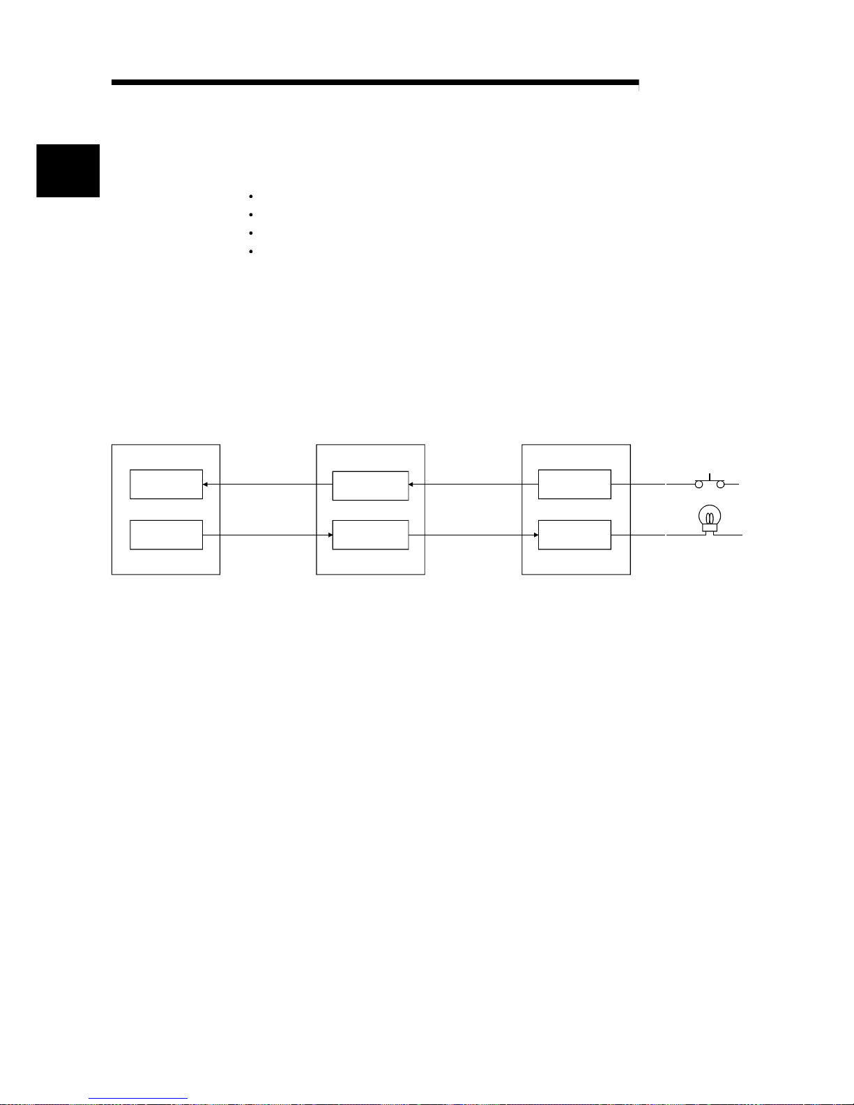
(1) Remote I/O station communication
The ON/OFF status of a switch or indicator lamp is communicated using the
remote input RX and remote output RY (see Section 4.2.1).
Input
Output
Remote input
RX
Remote output
RY
X
Y
Master stationPLC CPU Remote I/O station
Link scan
Link scan
Automatic refresh
Automatic refresh
1
Page 21
1 - 3 1 - 3
MELSEC-Q
1 OVERVIEW
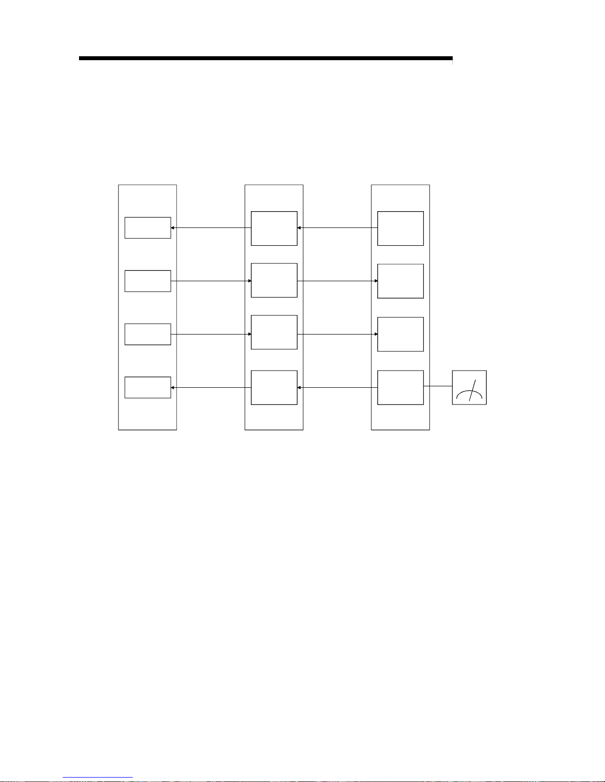
(2) Remote device station communication
Signals for handshaking with the remote device station (initial request, error
occurred flag, etc.) are communicated using the remote input RX and remote
output RY. The setting data to the remote device station are communicated using
remote registers RWw and RWr (see Section 4.2.2).
PLC CPU
X
Y
W
W
Master station
Remote
input
(RX)
Remote
output
(RY)
Remote
register
(RWw)
Remote
register
(RWr)
Automatic refresh
Automatic refresh
Automatic refresh
Automatic refresh
Link scan
Link scan
Link scan
Link scan
Remote device station
Voltmeter
Remote
input
(RX)
Remote
output
(RY)
Remote
register
(RWw)
Remote
register
(RWr)
Page 22
1 - 4 1 - 4
MELSEC-Q
1 OVERVIEW
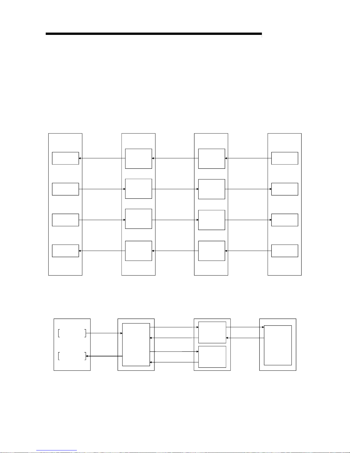
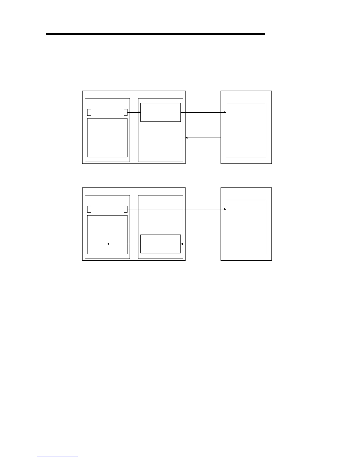
(3) Local station communication
Communication between the master station and the local station uses two types
of transmission methods: cyclic transmission and transient transmission (see
Section 4.2.3).
(a) Cyclic transmission
Data communication between the PLC CPUs can be performed in N:N
mode using bit data (remote input RX and remote output RY) and word data
(remote registers RWw and RWr).
PLC CPU
X
Y
W
W
Master station
X
Y
W
W
Remote
output
(RY)
Remote
input
(RX)
Remote
register
(RWw)
Remote
register
(RWr)
Remote
input
(RX)
Remote
output
(RY)
Remote
register
(RWw)
Remote
register
(RWr)
Automatic refresh
Automatic refresh
Automatic refresh
Automatic refresh
Link scan
Link scan
Link scan
Link scan
Automatic refresh
Automatic refresh
Automatic refresh
Automatic refresh
PLC CPU
Local station
(b) Transient transmission
Read (RIRD) or write (RIWT) operation of the local station buffer memory
and CPU device can be performed at any timing.
Master stationPLC CPU Local station
Transient transmission
PLC CPU
Transient transmission
Transient transmission
Transient transmission
Transient
transmission
area
Transient
transmission
area
Buffer
memory
W
RIWT
RIRD
Page 23
1 - 5 1 - 5
MELSEC-Q
1 OVERVIEW
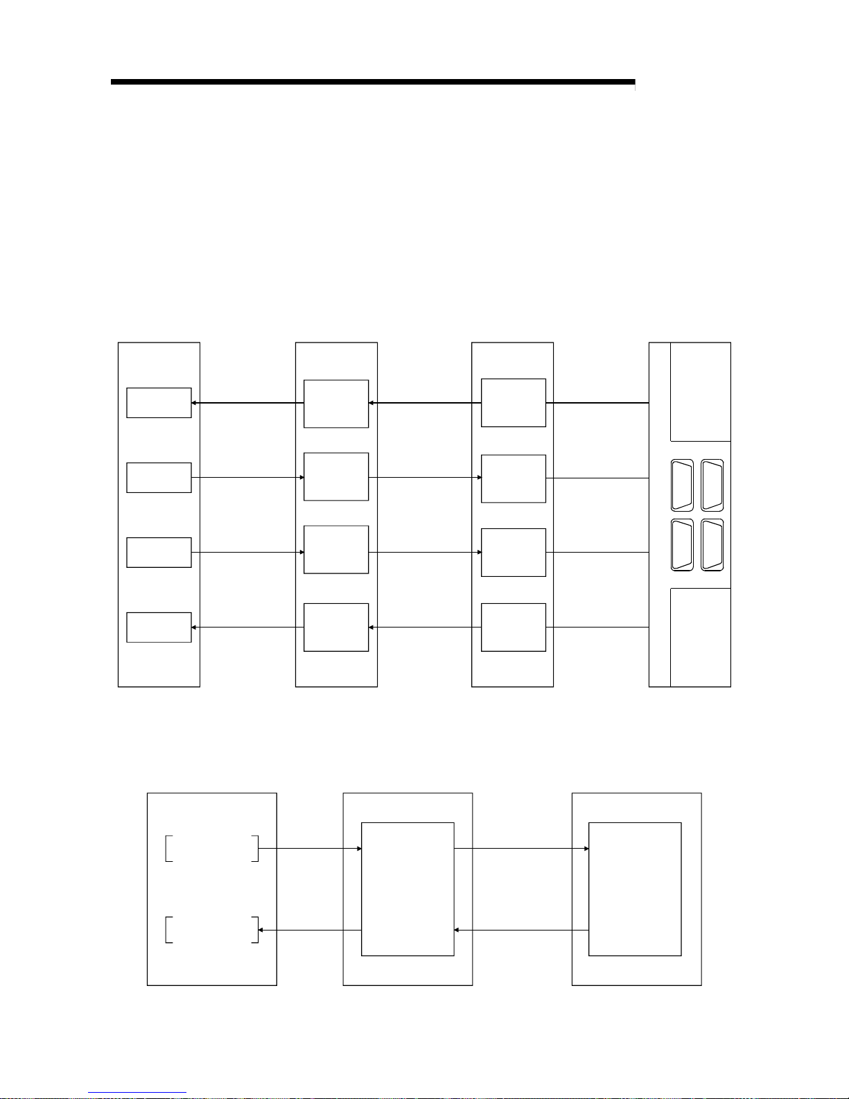
(4) Intelligent device station communication
Communication between the master station and the intelligent device station
uses two types of transmission methods: cyclic transmission and transient
transmission (see Section 4.2.4).
(a) Cyclic transmission
Signals for handshaking with the intelligent device station (positioning start,
positioning complete, etc.) are communicated using the remote input RX and
remote output RY. Numeric data (positioning start number, present feed
value, etc.) is communicated using remote registers RWw and RWr.
PLC CPU
X
Y
W
W
Master station
Remote
output
RY
Remote
input
RX
Remote
register
RWw
Remote
register
RWr
Remote
input
RX
Remote
output
RY
Remote
register
RWw
Remote
register
RWr
Automatic refresh
Automatic refresh
Automatic refresh
Automatic refresh
Link scan
Link scan
Link scan
Link scan
Intelligent device station
Servo amplifier
(b) Transient transmission
Read (RIRD) or written (RIWT) operation of the intelligent device station
buffer memory can be performed at any timing.
Master stationPLC CPU Intelligent device station
Transient transmission
Transient
transmission
area
Transient transmission
RIWT
RIRD
Buffer memory
Page 24
1 - 6 1 - 6
MELSEC-Q
1 OVERVIEW
(5) Parameter setting by GX Developer or the dedicated instruction
There are two parameter setting methods; the parameters can either be set by
GX Developer or by using a dedicated instruction (see Sections 2.2.1, 4.2.5 and
4.2.6).
The following table lists the differences between the two setting methods.
Program
requirement for
setting
parameters
Automatic
refresh
Number of
CPUs that can
be mounted
Changing the
parameter
settings while
the PLC CPU is
running
Parameter setting with
GX Developer
Not required
4 modules
Parameter setting with
dedicated instruction
Required
64 modules
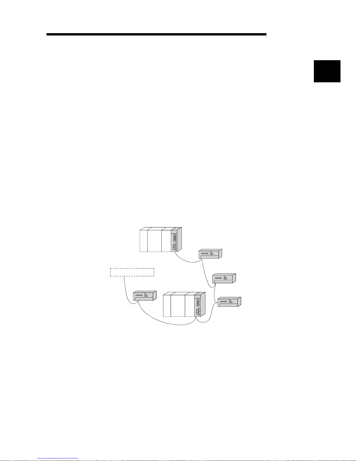
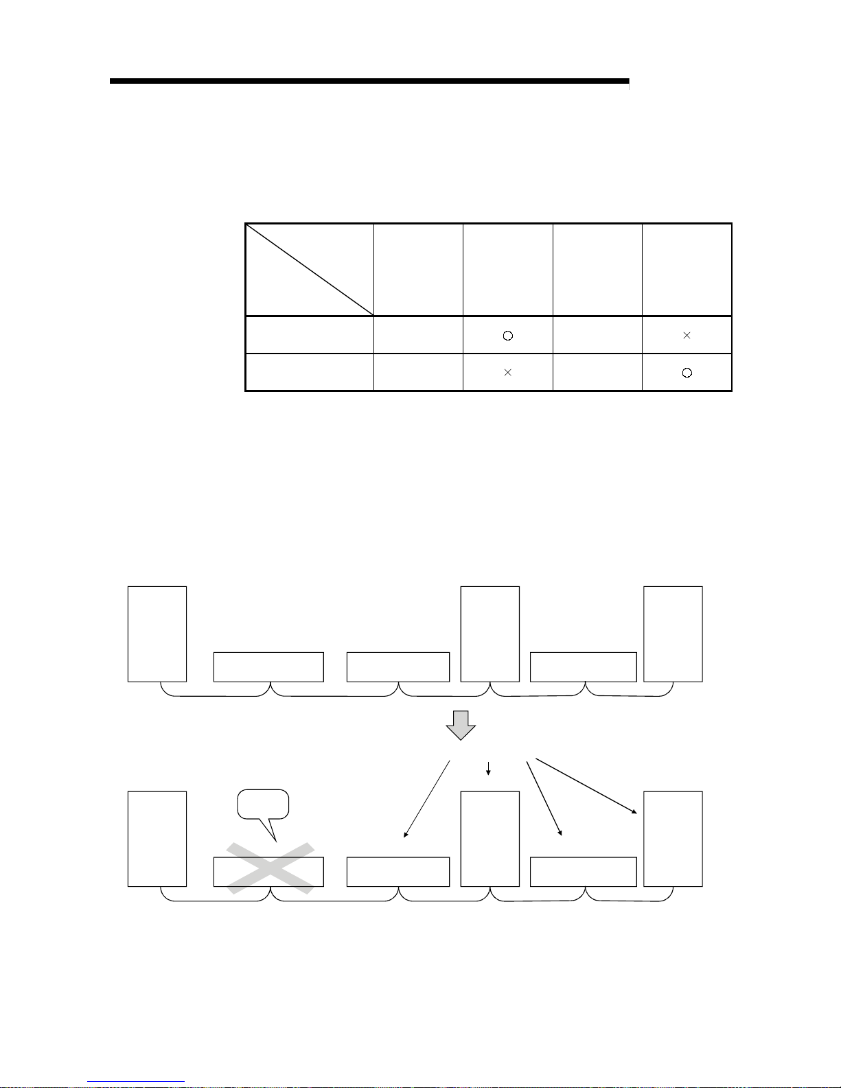
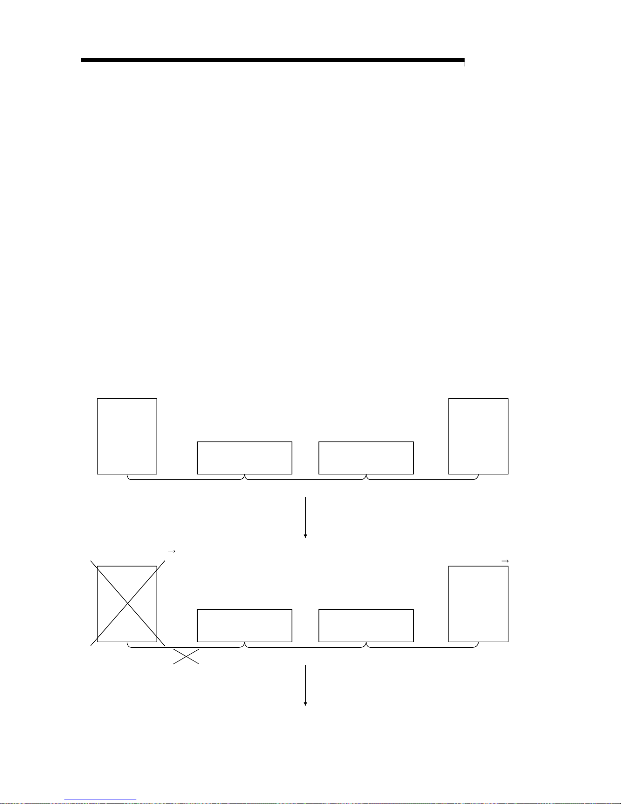
(6) System down prev ention ( Sl av e stati on cut- off function)
Because the system employs the bus connection method, even if a module
system fails due to power off, it will not affect the communication with other
normal modules.
Also, for a module using a 2-piece terminal block, the module can be replaced
during data link. (Replace the module after turning off the module power).
However, if the cable is disconnected, data link to all stations are disabled (see
Section 4.3.1).
Master
station
Remote station
(occupies 2 stations)
Remote station
(occupies 1 station)
Local
station
(occupies
1 station)
Remote station
(occupies 2 stations)
Local
station
(occupies
4 stations)
Station number 1 Station number 3 Station number 5
Station number 4 Station number 7
Master
station
Remote station
(occupies 2 stations)
Remote station
(occupies 1 station)
Local
station
(occupies
1 station)
Remote station
(occupies 2 stations)
Local
station
occupies
4 stations)
Station number 1 Station number 3 Station number 5
Station number 4 Station number 7
Data link continues
Faulty
station
(7) Automatic return function
When a station that has been disconnected from the link due to power off
recovers the normal status, it will join the data link automatically (see Section
4.3.2).
Page 25
1 - 7 1 - 7
MELSEC-Q
1 OVERVIEW
(8) Data link status setting when the master stati on PLC C PU has an
error
The data-link status can be set to either "stop" or "continue" when an error
causing the operation to stop such as "SP. UNIT ERROR" occurs in the PLC
CPU at the master station. With errors enabling the operation to continue such as
"BATTERY ERROR," the data link will continue regardless of the setting (see
Section 4.3.3).
(9) Setting the status of input data from a data link faulty station
The data entered (received) from a data-link faulty station can be cleared or the
previous status immediately before the error can be maintained (see Section
4.3.4).
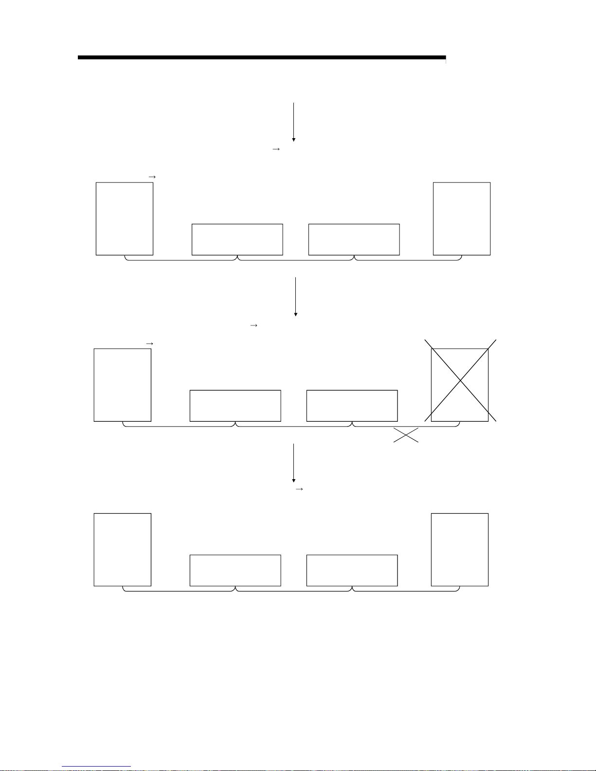
(10) Standby master function
This function enables the data link to continue working by switching to a standby
master station (backup station for the master station) if a malfunction occurs in
the master station due to a malfunction of the PLC CPU or power supply.
The master station can return to online even during data link control by the
standby master station, and prepares itself for standby master station system
down (see Section 4.3.6).
Data link control by the master station
Master station
Remote device stat ion
Station number 2
Number of occupied stations: 2
Intelligent device station
Station number 4
Number of occupied stations: 1
Standby master station
Station number 1
Number of occupied stations: 1
Data link
control in
progress
Standby
Cyclic communication Cyclic communication Cyclic communication
Remote device stat ion
Station number 2
Number of occupied stations: 2
Intelligent device station
Station number 4
Number of occupied stations: 1
Data link
control in
progress
Cyclic communication Cyclic communication Cyclic communication
To the next page
Standby master station
Station number 1 0
Master station is down Data link control by the standby master station
Master station
Page 26
1 - 8 1 - 8
MELSEC-Q
1 OVERVIEW
Remote device stat ion
Station number 2
Number of occupied stations: 2
Intelligent device station
Station number 4
Number of occupied stations: 1
Standby master station
Data link
control in
progress
Cyclic communication Cyclic communication Cyclic communication
Remote device stat ion
Station number 2
Number of occupied stations: 2
Intelligent device station
Station number 4
Number of occupied stations: 1
Standby master station
Station number 1
Number of occupied stations: 1
Data link
control in
progress
Standby
C
y
clic communication Cyclic communication Cyclic communication
Continued from the previous page
Master station
Problem occurrence in the standby master station Data link control by the master station
Master station
Station number 1 0
Standby master station returns to normal and comes back online
Standby master station prepares itself for master station system down
Remote device stat ion
Station number 2
Number of occupied stations: 2
Intelligent device station
Station number 4
Number of occupied stations: 1
Standby master station
Station number 0
Data link
control in
progress
Standby
Cyclic communication Cyclic communication Cyclic communication
Master station returns to normal and comes back online
Master station prepares itself for standby master station system down
Master station
Station number 0 1
Page 27
1 - 9 1 - 9
MELSEC-Q
1 OVERVIEW
(11) Remote device station initi ali zation procedure registration function
This function performs the initial setting for the remote device station using the
GX Developer, without creating a sequence program (see Section 4.4.1).
(12) Event issuance for the interrupt prog r am
This function issues an event when the conditions set by the GX Developer are
established in order to make the PLC CPU execute the interrupt program (see
Section 4.4.2).
(13) Automatic CC-Link startup
By installing the QJ61BT11N, the CC-Link is started up and all data are refreshed
by simply turning on the power, without creating a sequence program. However,
when the number of connected modules is less than 64, it is necessary to set the
network parameters in order to optimize the link scan time (see Section 4.4.3.).
(14) Selecting a mode according to the sy stem
The CC-Link system has four types of modes according to various systems. (See
sections 4.4.4, 4.4.5 and 4.4.14.)
The overview of the modes is described in the following table.
Mode Connectable Overview
Remote net ver. 1 mode
Mode in which complete compatibility with the
conventional module (QJ61BT11) is achieved.
Select this mode when the number of cyclic points need
not be increased or when the QJ61BT11N is used to
replace the conventional module as a maintenance
product.
Remote net ver. 2 mode
Select this mode when increasing the number of cyclic
points and configuring a new system.
Remote net additional mode
Remote I/O station
Remote device station
Intelligent device station
Local station
Standby master station
Select this mode when adding a ver.2 compatible slave
station to the existing system to increase the number of
cyclic points.
Remote I/O net mode Remote I/O station
Select this mode when the system consists of only the
master station and remote I/O stations.
Since cyclic transmission is made at high speed, the link
scan time can be reduced.
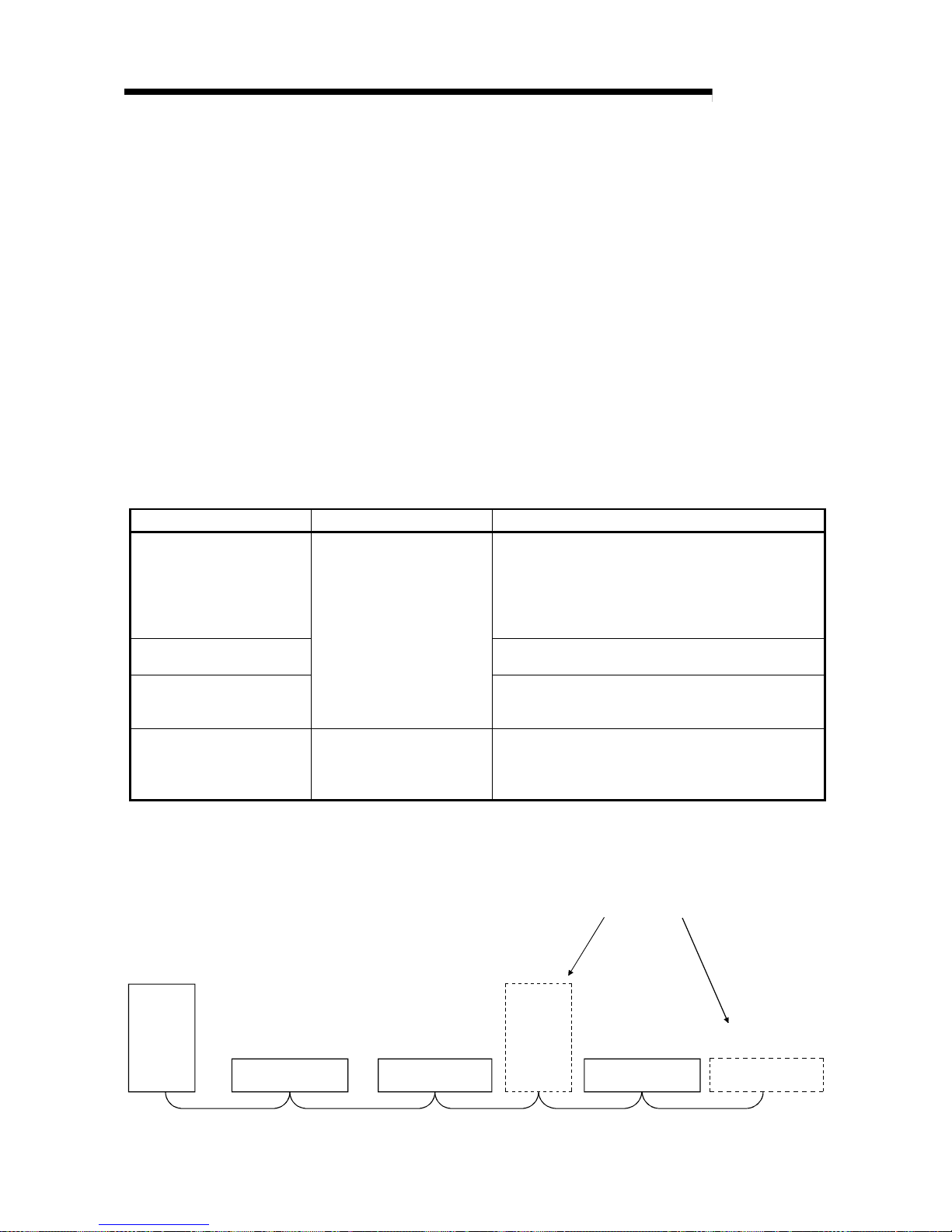
(15) Reserved station function
Stations that are not actually connected (stations to be connected in the future)
will not be treated as faulty stations if they are specified as reserved stations.
The reserved stations can also be set as 0 points. (see Section 4.4.6).
Master
station
Remote station
(occupies 2 stations)
Remote station
(occupies 1 station)
Local
station
(occupies
4 stations)
Remote station
(occupies 2 stations)
Station number 1 Station number 3 Station number 8
(Reserved station)
Station number 4
Remote station
(occupies 1 station)
(Reserved station)
Station number 10
Stations that will be connected in the future
Page 28
1 - 10 1 - 10
MELSEC-Q
1 OVERVIEW
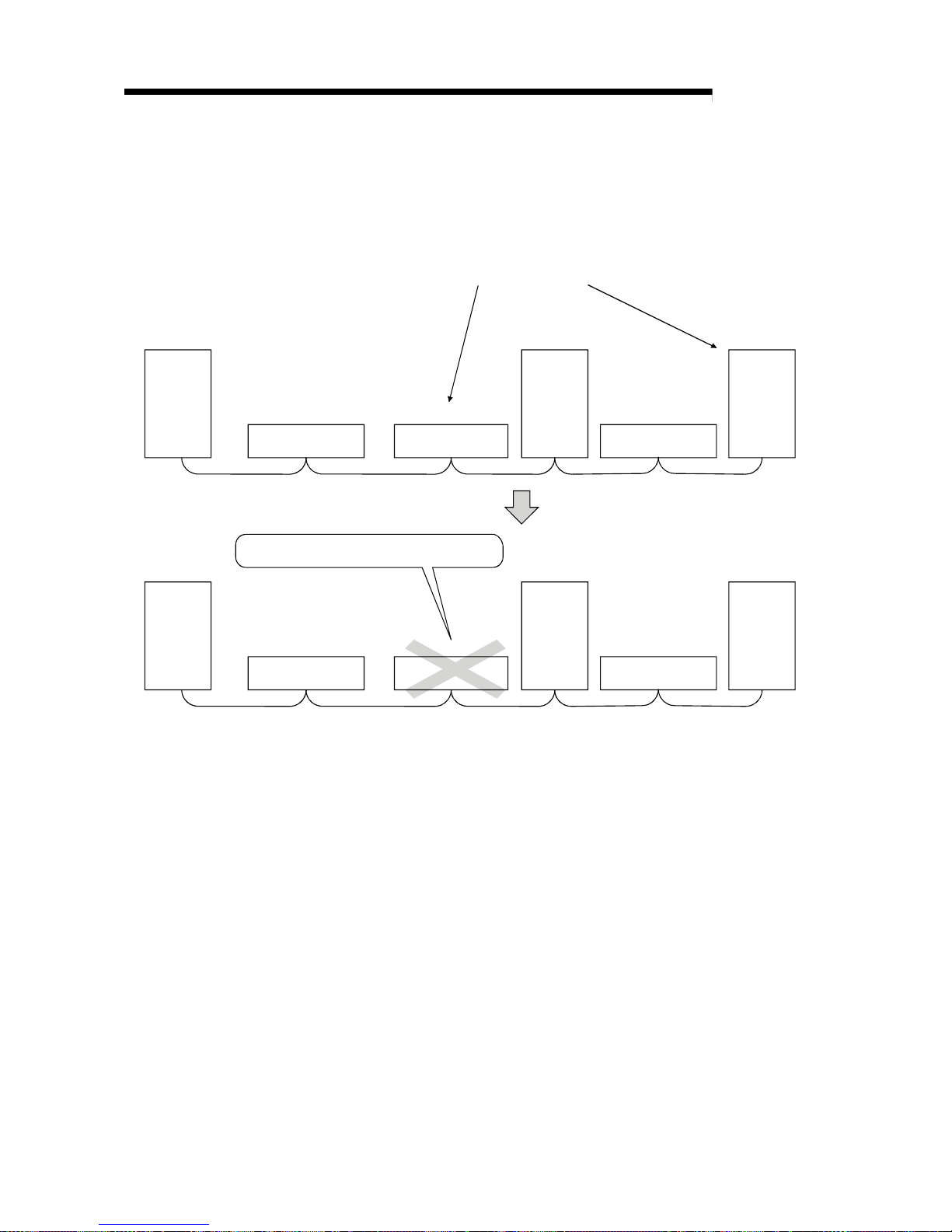
(16) Error invalid station setti ng function
By setting the network parameters, the module that is powered off in the system
configuration will not be treated as a "data link faulty station" by the master
station and local station. However, caution is required since errors are no longer
detected (see Section 4.4.7).
Master
station
Remote station
(occupies 2 stations)
Remote station
(occupies 1 station)
Local
station
(occupies
1 station)
Remote station
(occupies 2 stations)
Local
station
(occupies
4 stations)
Station number 1 Station number 3 Station number 5
Station number 4 Station number 7
Master
station
Remote station
(occupies 2 stations)
Remote station
(occupies 1 station)
Local
station
(occupies
1 station)
Remote station
(occupies 2 stations)
Local
station
(occupies
4 stations)
Station number 1 Station number 3 Station number 5
Station number 4 Station number 7
This station does not become a data link f aul ty station.
Stations to be specified as error invalid stations
(17) Scan synchronous function
This function synchronizes the link scan to the sequence scan (see Section
4.4.8).
(18) Temporary error inv al i d station setti ng function
With this function, the module specified by the GX Developer will not be treated
as a "data link faulty station" by the master or local station while in online. The
module can be replaced without detecting an error in online (see Section 4.4.9).
(19) Data link stop/restart
The data link can be stopped and restarted while it is being used (see Section
4.4.10).
(20) Station number overlap checking function
This function checks the status of the connected stations to see if the number of
occupied stations is overlapping or if there is more than one station with the
station number setting of 0 in the system (see Section 4.4.11).
Page 29
1 - 11 1 - 11
MELSEC-Q
1 OVERVIEW
(21) Transient transmission
With this method of transmission, the counterpart is specified and 1:1
communication is performed at an arbitrary timing (see Section 4.5).
Local station
PLC CPU
RIWT
Buffer memory
Device memory
Master module
Send buffer
Master station
Local station
PLC CPU
RIRD
Buffer memory
Device memory
Master module
Send buffer
Master station
Page 30

1 - 12 1 - 12
MELSEC-Q
1 OVERVIEW
(22) Compatibility with conventional module
The QJ61BT11N achieves complete compatibility with the conventional module
(QJ61BT11) in the remote net ver. 1 mode.
Select the remote net ver. 1 mode when the number of cyclic points need not be
increased or when the QJ61BT11N is used to replace the conventional module
as a maintenance product.
(23) Cyclic points increase
Selection of the remote net ver. 2 mode or remote net additional mode allows
RX/RY to be increased to up to 8192 points and RWr/RWw to up to 2048 words
per network by making expanded cyclic setting (single, double, quadruple,
octuple).
Also, RX/RY can be increased to up to 224 points and RWr/RWw to up to 32
words per station. (See Section 4.4.14.)
(24) Remote I/O station points setting
Set the number of I/O points of a remote I/O station.
This setting minimizes CPU device assignment and reduces the reserved points
of remote input RX and remote output RX for remote I/O stations. (See Section
4.4.13.)
(25) Slave station refresh/compulsory clear setti ng in case of PLC CPU
STOP
Set whether output data to the remote, local, intelligent device and standby
master stations will be refreshed or compulsorily cleared when the PLC CPU
comes to STOP. (See Section 4.3.5.)
Page 31

2 - 1 2 - 1
MELSEC-Q
2 SYSTEM CONFIGURATION
2 SYSTEM CONFIGURATION
The system configuration for the CC-Link is described below.
2.1 System Configuration
(1) Remote net ver. 1 mode
A total of 64 remote I/O stations, remote device stations, local stations, standby
master stations, or intelligent device stations can be connected to a single master
station.
However, the following conditions must all be satisfied.
Condition 1 {(1 a) + (2 b) + (3 c) + (4 d)} ≤ 64
a: Number of modules occupying 1 station
b: Number of modules occupying 2 stations
c: Number of modules occupying 3 stations
d: Number of modules occupying 4 stations
Condition 2 {(16 A) + (54 B) + (88 C)} ≤ 2304
A: Number of remote I/O stations
≤
64
B: Number of remote device stations
≤
42
C: Number of local stations, standby master stations
and intelligent device stations
≤
26
Analog/digital
converter module
AJ65BT-64AD
Remote I/O module
AJ65BTB1-16D
AJ65BTC-32D
Intelligent device station Remote device station Remote I/O station
Maximum 26 Maximum 42 Maximum 64
Terminal resistor (required)
CC-Link dedicated cable
CC-Link dedicated cable
Maximum 26
Total 64
RS-232C
Interface module
AJ65BT-R2
A1SJ61QBT11
AJ61QBT11
Local station
A1SJ61BT11
AJ61BT11
Local station
QJ61BT11
Local station
A1SJ61BT11
AJ61BT11
Master station
T
erminal resistor (required)
A1SJ61QBT11
AJ61QBT11
Master station
QJ61BT11
Master station
1 module for each system
QJ61BT11N
QJ61BT11N
2
Page 32

2 - 2 2 - 2
MELSEC-Q
2 SYSTEM CONFIGURATION
(2) Remote net ver. 2 mode, remote net additional mode
A total of 64 remote I/O stations, remote device stations, local stations, standby
master stations, or intelligent device stations can be connected to a single master
station.
However, the following conditions must all be satisfied.
Condition 1
{(a + a2 + a4 + a8)
+ (b + b2 + b4 + b8)
2
+ (c + c2 + c4 + c8) 3
+ (d + d2 + d4 + d8) 4} ≤ 64
Condition 2
[{(a
32) + (a2 32) + (a4 64) + (a8 128)}
+ {(b
64) + (b2 96) + (b4 192) + (b8 384)}
+ {(c
96) + (c2 160) + (c4 320) + (c8 640)}
+ {(d 128) + (d2 224) + (d4 448) + (d8 896)}] ≤ 8192
Condition 3
[{(a
4) + (a2 8) + (a4 16) + (a8 32)}
+ {(b
8) + (b2 16) + (b4 + 32) + (b8 64)}
+ {(c 12) + (c2 24) + (c4 48) + (c8 96)}
+ {(d 16) + (d2 32) + (d4 64) + (d8 128)}] ≤ 2048
a: The total number of ver.1 compatible slave
stations that occupy 1 station, and ver.2
compatible slave stations that occupy 1 station
which are set to “Single”.
b: The total number of ver.1 compatible slave
stations that occupy 2 stations, and ver.2
compatible slave stations that occupy 2 stations
which are set to “Single”.
c: The total number of ver.1 compatible slave
stations that occupy 3 stations, and ver.2
compatible slave stations that occupy 3 stations
which are set to “Single”.
d: The total number of ver.1 compatible slave
stations that occupy 4 stations, and ver.2
compatible slave stations that occupy 4 stations
which are set to “Single”.
a2: The number of ver.2 compatible stations that
occupy 1 station which are set to “Double”.
b2: The number of ver.2 compatible stations that
occupy 2 stations which are set to “Double”.
c2: The number of ver.2 compatible stations that
occupy 3 stations which are set to “Double”.
d2: The number of ver.2 compatible stations that
occupy 4 stations which are set to “Double”.
a4: The number of ver.2 compatible stations that
occupy 1 station which are set to “Quadruple”.
b4: The number of ver.2 compatible stations that
occupy 2 stations which are set to “Quadruple”.
c4: The number of ver.2 compatible stations that
occupy 3 stations which are set to “Quadruple”.
d4: The number of ver.2 compatible stations that
occupy 4 stations which are set to “Quadruple”.
a8: The number of ver.2 compatible stations that
occupy 1 station which are set to “Octuple”.
b8: The number of ver.2 compatible stations that
occupy 2 stations which are set to “Octuple”.
c8: The number of ver.2 compatible stations that
occupy 3 stations which are set to “Octuple”.
d8: The number of ver.2 compatible stations that
occupy 4 stations which are set to “Octuple”.
Condition 4 {(16 A) + (54 B) + (88 C) } ≤ 2304
A: Number of remote I/O stations
≤
64
B: Number of remote device stations
≤
42
C: Number of local stations, standby master
stations and intelligent device stations
≤
26
2
Page 33

2 - 3 2 - 3
MELSEC-Q
2 SYSTEM CONFIGURATION
Analog/digital
converter module
AJ65VBTCU-68ADVN
AJ65VBTCU-68ADIN
Remote I/O module
AJ65BTB1-16D
AJ65BTC-32D
Intelligent device station Remote device station Remote I/O station
Maximum 26 Maxim u m 4 2 Maximum 64
Terminal resistor (required)
CC-Link dedicated cable
CC-Link dedicated cable
Maximum 26
Total 64
RS-232C
Interface module
AJ65BT-R2
A1SJ61QBT11
AJ61QBT11
Local station
A1SJ61BT11
AJ61BT11
Local station
QJ61BT11
Local station
Terminal resistor (required)
QJ61BT11N
Master station
1 module for each system
QJ61BT11N
Page 34

2 - 4 2 - 4
MELSEC-Q
2 SYSTEM CONFIGURATION
2.2 Applicable System
Applicable PLC CPUs and notes on the system configuration are described below.
2.2.1 Applicable modules and number of CPUs that can be mounted
(1) Applicable modules and number of CPUs that can be mounted
The CPU modules and network modules (for remote I/O station) to which the
QJ61BT11N can be installed and number of modules that can be installed are
listed in the table below.
(a) When performing the parameter setting with the GX Developer
Applicable module Number of CPUs that can be mounted Remark
Q00JCPU
Q00CPU
Q01CPU
Maximum 2
(1) (2)
Q02CPU
Q02HCPU
Q06HCPU
Q12HCPU
Q25HCPU
Maximum 4
It can be
mounted only
with the Q
mode.
(
1
) (3)
Q12PHCPU
Q25PHCPU
Maximum 4
(
1
) (2)
CPU
module
Q12PRHCPU
Q25PRHCPU
Maximum 4
(
1
) (2) (4)
Network
module
QJ72LP25-25
QJ72LP25G
QJ72BR15
Maximum 4
(
2
)
1 See User’s Manual (Function Explanation, Program Fundamentals) for the CPU
module to use.
2 Incompatible with the remote net additional mode. When the module is used,
operation cannot be guaranteed.
3 For use in the remote net additional mode, use the PLC CPU whose first
five digits of serial No. are 05032 or later.
If the incompatible PLC CPU is used, operation cannot be guaranteed.
4 For use in a redundant system, select the QJ61BT11N with first five digits of
serial No. "06052" or later.
When incompatible QJ61BT11N is used, the operation cannot be
guaranteed.
Page 35

2 - 5 2 - 5
MELSEC-Q
2 SYSTEM CONFIGURATION
(b) When performing the parameter setting with the dedicated instructions.
Applicable module
Number of CPUs that can be mounted (
3
)
Remark
Q00JCPU
Q00CPU
Q01CPU
Maximum 2
(1) (2)
Q02CPU
Q02HCPU
Q06HCPU
Q12HCPU
Q25HCPU
Maximum 64
It can be
mounted only
with the Q
mode.
(1) (3)
CPU
module
Q12PHCPU
Q25PHCPU
Maximum 64
(
1
) (2)
1 See User’s Manual (Function Explanation, Program Fundamentals) for the CPU
module to use.
2 Incompatible with the remote net additional mode. When the module is used,
operation cannot be guaranteed.
3 For use in the remote net additional mode, use the PLC CPU whose first
five digits of serial No. are 05032 or later.
If the incompatible PLC CPU is used, operation cannot be guaranteed.
(2) Mountable base unit
QJ61BT11N can be mounted on any of the base unit’s I/O slots ( 4). However,
depending on combinations with other mounted modules and the number of
mountings, there may be cases where the power capacity is insufficient. Be sure
to consider the power capacity when mounting the module.
4 Must be inside the point number range of 1 CPU unit and network module (for remote
I/O station).
(3) Applicable software package
The software package available for the QJ61BT11N is listed below:
Manual name Model name Remarks
GX Developer
SWnD5C-GPPW-E
5
Required MELSEC PLC
programming software.
"n" in the model name is 4 or
greater.
5 The product of Version 8.03D or later is required for use in the remote net ver. 2
mode or remote net additional mode.
(4) Usable slave stations
Any of ver. 1 compatible slave stations and ver. 2 compatible slave stations is
usable.
Page 36

2 - 6 2 - 6
MELSEC-Q
2 SYSTEM CONFIGURATION
2.2.2 Notes on the system configuration
The system should be designed with the following considerations to prevent mis-input
from the remote I/O modules:
(1) When powering on and off
Start the data link after turning on the power to the remote I/O modules. Turn off
the power to the remote I/O modules after stopping the data link.
During operation
During stop
ON
OFF
Master module
(data link status)
Remote I/O module
(power status)
Data link start Data link stop
(2) During momentary pow er failure of the remote I/O modules
When a momentary power failure occurs in the power (24 V DC) being supplied
to the remote I/O modules, mis-input may occur.
(a) Cause for mis-input due to a momentary power failure
The remote I/O module hardware uses the power by internally converting
the module power (24 V DC) to 5 V DC.
When a momentary power failure occurs in a remote I/O module, the
following condition occurs:
(Time for the 5 V DC power in the remote I/O module to turn off) >
(Response time for input module on
off)
Therefore, mis-input occurs when a refresh is performed within the time
indicated by 1) in the figure below.
Remote I/O module
(module power supply and input
external supply power)
Remote I/O module (internal 5 V DC)
Input (Xn)
1)
When the input external power supply turns OFF, the
input (Xn) turns OFF after the response time for the
input module to change from ON to OFF.
Page 37

2 - 7 2 - 7
MELSEC-Q
2 SYSTEM CONFIGURATION
(b) Countermeasure for mis-input
For the power supply module, the stabilized power supply and the input
external supply power of AC input, wire the power cables from the same
power source.
For DC input
~
Power supply module
PLC CPU
Remote I/O module
Module power supply
Input externalsupply power
Stabilized
power supply
24 V DC
Master module
For AC input
~
24 V DC
Power supply module
PLC CPU
Remote I/O module
Module power supply
Input external-
supply power
Stabilized
power supply
Master module
REMARK
When supplying power from a single power source to multiple remote I/O modules,
select the proper type of cable and perform the wiring in consideration of the voltage
decline.
Connections can be established if the receiving port voltage at the remote I/O
module is within the specified range of the remote I/O module to be used.
~
Stabilized
power supply
Remote moduleRemote module
Page 38

2 - 8 2 - 8
MELSEC-Q
2 SYSTEM CONFIGURATION
2.2.3 How to check the function version
The following describes how to check the function version.
(1) How to check the function version of the QJ61BT11N
(a) Checking the "SERIAL column of the rating plate" on the module side
Serial No. (first 5 digits)
Function version
MADE IN JAPAN
MODEL
SERIAL
050320000000000-B
Conformed standard
(b) See Section 13.4 for how to check the function version with GX Developer.
Page 39

2 - 9 2 - 9
MELSEC-Q
2 SYSTEM CONFIGURATION
2.2.4 CC-Link version
There are two types of CC-Link version, i.e., Ver.1 and Ver.2.
(1) Definition of Ver.1.00 and Ver.1.10
Version 1.10 modules have a uniform station-to-station cable length of 20 cm or
more by improving the restrictions on the conventional station-to-station cable
length.
In contrast, the conventional modules are defined as Version 1.00.
See Section 3.1.2 for the maximum overall cable distance of Version 1.10.
In order to make the station-to-station cable length uniformly 20 cm or more, the
following conditions are required:
1) All the modules that configure the CC-Link system must be compatible with
Ver.1.10.
2) All the data link cables must be CC-Link dedicated cables conforming to Version
1.10.
POINT
The specifications for Version 1.00 should be used for the maximum cable overall
distance and station-to-station cable length if a system contains modules and
cables of both Version 1.00 and Version 1.10.
See Section 3.1.1 for the maximum overall cable distance and station-to-station
cable length of Version 1.00.
(2) Definition of Ver.2
As Ver.2 is characterized as increase of cyclic transmission data size,
Ver.2-compatible module is defined to support this function.
(3) Checking version
The modules including CC-Link logo on the rated plate are compatible with
Ver.1.10.
The modules including V2 logo on the rated plate are compatible with Ver.2.
MADE IN JAPAN
MODEL
SERIAL
050320000000000-B
Conformed standard
Page 40

3 - 1 3 - 1
MELSEC-Q
3 SPECIFICATIONS
3 SPECIFICATIONS
This section describes the specifications of the QJ61BT11N.
For the general specifications of the QJ61BT11N, refer to the user's manual for the
CPU module to be used.
3.1 Performance Specifications
Table 3.1 lists the performance specifications of the OJ61BT11N.
Table 3.1 Performance specifications
Item Specification
Transmission rate Can select from 156 kbps/ 625 kbps/ 2.5 Mbps/ 5 Mbps/ 10 Mbps
Maximum overall cable distance
(Maximum transmission distance)
Varies according to the transmission rate (See Section 3.1.1, 3.1.2)
Maximum number of connected stations
(master station)
64 (See Section 2.1)
Number of occupied stations
(local station)
1 to 4 stations
The number of stations can be switched using the GX Developer parameter setting.
1
Remote I/O (RX, RY) : 2048 points
Remote register (RWw) : 256 points (master station remote device station/local station/ intelligent
device station/standby master station)
Maximum number of link points per system
1
Remote register (RWr) : 256 points (remote device station/local station/ intelligent device station/standby
master station
master station)
Remote I/O (RX, RY) : 32 points (local station is 30 points)
Remote register (RWw) : 4 points (master station remote device station/local station/ intelligent
device station/standby master station)
Remote station/local station/intelligent device
station/standby master station
Number of link points per station
1
Remote register (RWr) : 4 points (remote device station/local station/ intelligent device station/standby
master station
master station)
Communication method Polling method
Synchronous method Flag synchronous method
Encoding method NRZI method
Transmission path Bus (RS-485)
Transmission format Conforms to HDLC
Error control system CRC (X16 + X12 + X5 + 1)
Connection cable
CC-Link dedicated cable/ CC-Link dedicated high-performance cable/
Ver.1.10 compatible CC-Link dedicated cable
2
RAS function
Automatic return function
Slave station cut-off function
Error detection by the link special relay/register
Number of I/O occupied points 32 points (I/O assignment: Intelligent 32 points)
5 V DC internal current consumption 0.46 A
Weight 0.12 kg
1 Indicates the number of link points for remote net ver.1 mode. For number of link points for remote net
ver.2 mode/remote net additional mode. Refer to the table 3.2.
2 CC-Link dedicated high-performance cables cannot be used with other cables such as CC-Link dedicated
cables or Ver.1.10 compatible CC-Link dedicated cables. Also attach the terminating resister which
matches the kind of the cable. (Refer to section 7.5)
3
Page 41

3 - 2 3 - 2
MELSEC-Q
3 SPECIFICATIONS
Table 3.2 Number of link points for remote net ver.2 mode/remote net additi onal mode
Item Specifications
Maximum No. of link points per system
Remote I/O (RX, RY) : 8192 points
Remote register (RWw) : 2048 points (master station
remote device
station/local station/intelligent device
station/standby master station)
Remote register (RWr) : 2048 points (remote device station/local
station/intelligent device station/standby
master station
master station)
Expanded cyclic setting Single Double Quadruple Octuple
Remote I/O (RX, RY)
32 points
(30 points
for local
station)
32 points
(30 points
for local
station)
64 points
(62 points
for local
station)
128 points
(126 points
for local
station)
Remote register (RWw) 4 points 8 points 16 points 32 points
No. of link
points per
station
Remote register (RWr) 4 points 8 points 16 points 32 points
Remote I/O
(RX, RY)
32 points 32 points 64 points 128 points
Remote
register (RWw)
4 points 8 points 16 points 32 points
Occupies
1 station
Remote
register (RWr)
4 points 8 points 16 points 32 points
Remote I/O
(RX, RY)
64 points 96 points 192 points 384 points
Remote
register (RWw)
8 points 16 points 32 points 64 points
Occupies
2 stations
Remote
register (RWr)
8 points 16 points 32 points 64 points
Remote I/O
(RX, RY)
96 points 160 points 320 points 640 points
Remote
register (RWw)
12 points 24 points 48 points 96 points
Occupies
3 stations
Remote
register (RWr)
12 points 24 points 48 points 96 points
Remote I/O
(RX, RY)
128 points 224 points 448 points 896 points
Remote
register (RWw)
16 points 32 points 64 points 128 points
Number
of link
points per
number of
occupied
stations
Occupies
4 stations
Remote
register (RWr)
16 points 32 points 64 points 128 points
3
Page 42

3 - 3 3 - 3
MELSEC-Q
3 SPECIFICATIONS
3.1.1 Maximum overall cabl e di stance ( for Ver. 1.00)
The relationship between the transmission speed and the maximum overall cable
distance is described below:
(1) For a system consisting of only remote I/O stations and remote
device stations
Master station
Remote I/O station
or remote
device station
2 2 1 1
Maximum overall cable distance
Remote I/O station
or remote
device station
Remote I/O station
or remote
device station
Remote I/O station
or remote
device station
1 Cable length between remote I/O stations or remote device stations.
2 Cable length between the master station and the adjacent stations.
CC-Link dedicated cable (uses terminal resistor 110 Ω)
Station-to-station cable length
Transmission rate
1
2
Maximum overall cable
distance
156 kbps 1200 m (3937.2 ft.)
625 kbps 600 m (1968.6 ft.)
2.5 Mbps
30 cm (11.81 in.) or more
200 m (656.2 ft.)
30 cm (11.81 in.) to
59 cm (23.23 in.)
110 m (360.9 ft.)
5 Mbps
60 cm (23.62 in.) or more 150 m (492.15 ft.)
30 cm (11.81 in.) to
59 cm (23.23 in.)
50 m (164.1 ft.)
60 cm (23.62 in.) to
99 cm (38.98 in.)
80 m (262.5 ft.)
10 Mbps
1 m (3.28 ft.) or more
1 m (3.28 ft.) or more
100 m (328.1 ft.)
CC-Link dedicated high performance cable (uses terminal resistor 130 Ω)
Station-to-station cable length
Transmission rate
1
2
Maximum overall cable
distance
156 kbps 1200 m (3937.2 ft.)
625 kbps 900 m (2952.9 ft.)
2.5 Mbps 400 m (1312.4 ft.)
5 Mbps 160 m (524.96 ft.)
Number of connected
stations: 1 to 32
30 cm (11.81 in.) or more
100 m (328.1 ft.)
30 cm (11.81 in.) to
39 cm (15.35 in.)
80 m (262.5 ft.)
Number of connected
stations: 33 to 48
40 cm (15.75 in.) or more 100 m (328.1 ft.)
30 cm (11.81 in.) to
39 cm (15.35 in.)
20 m (65.52 ft.)
40 cm (15.75 in.) to
69 cm (27.17 in.)
30 m (98.43 ft.)
10 Mbps
Number of connected
stations: 49 to 64
70 cm (27.56 in.) or more
1 m (3.28 ft.) or more
100 m (328.1 ft.)
The cable length between remote I/O stations or remote device stations is within
this range and if even one location is wired, the maximum overall cable distance will
be as indicated above.
Page 43

3 - 4 3 - 4
MELSEC-Q
3 SPECIFICATIONS
(Example) When the transmission rate is 10 Mbps, and 43 remote I/O stations and
remote device stations are connected using the CC-Link dedicated high
performance cable, because the cable connecting the second and third
stations is "35 cm (13.78 in.)", the maximum overall cable distance will
be "80 cm (31.5 in.)".
Master station
Remote device
station
1 m (3.28 ft.) 50 cm (19.69 in.) 35 cm (13.78 in.) 50 cm (19.69 in.)
Remote I/O stationRemote I/O station
Remote device
station
First Second Third 4th
Remote I/O station
43th
(2) For a system consisting of remote I/O stations, remote device
stations, local stations and intelligent device stations
Master station
Remote I/O station
or remote
device station
Remote I/O station
or remote
device station
Local station
or intelligent
device station
Local station
or intelligent
device station
2 1
Maximum overall cable distance
2 2
1 Cable length between remote I/O stations or remote device stations
2 Cable length between the master station or the local or intelligent device station
and the adjacent stations
CC-Link dedicated cable (uses terminal resistor 110 Ω)
Station-to-station cable length
Transmission rate
1
2
Maximum overall cable
distance
156 kbps 1200 m (3937.2 ft.)
625 kbps 600 m (1968.6 ft.)
2.5 Mbps
30 cm (11.81 in.) or more
200 m (656.2 ft.)
5 Mbps
30 cm (11.81 in.) to
59 cm (23.23 in.)
110 m (360.9 ft.)
60 cm (23.62 in.) or more 150 m (492.15 ft.)
30 cm (11.81 in.) to
59 cm (23.23 in.)
50 m (164.1 ft.)
60 cm (23.62 in.) to
99 cm (38.98 in.)
80 m (262.5 ft.)
10 Mbps
1 m (3.28 ft.) or more
2 m (6.56 ft.) or more
100 m (328.1 ft.)
CC-Link dedicated high performance cable (uses terminal resistor 130 Ω)
Station-to-station cable length
Transmission rate
1
2
Maximum overall cable
distance
156 kbps 1200 m (3937.2 ft.)
625 kbps 600 m (1968.6 ft.)
2.5 Mbps
30 cm (11.81 in.) or more
200 m (656.2 ft.)
30 cm (11.81 in.) to
59 cm (23.23 in.)
110 m (360.9 ft.)
5 Mbps
60 cm (23.62 in.) or more 150 m (492.15 ft.)
70 cm (27.56 in.) to
99 cm (38.98 in.)
50 m (164.1 ft.)
10 Mbps
1 m (3.28 ft.) or more
2 m (6.56 ft.) or more
80 m (262.5 ft.)
The cable length between remote I/O stations or remote device stations is within
this range and if even one location is wired, the maximum overall cable distance will
be as indicated above.
Page 44

3 - 5 3 - 5
MELSEC-Q
3 SPECIFICATIONS
3.1.2 Maximum overall cabl e di stance ( for Ver. 1.10)
The relation of the transmission speed and maximum overall cable distance when
configuring the entire system with Version 1.10 modules and cable is shown below.
Remote I/O station
or remote
device station
Maximum overall cable distance
Master station
Local station or
intelligent device
station
Local station or
intelligent device
station
Station to station
cable length
Remote I/O station
or remote
device station
Version 1.10 compatible CC-Link dedicated cable ( ter mi nal r esi stor of 110Ω used)
Transmission speed Station to station cable length Maximum overall cable distance
156kbps 1200m
625kbps 900m
2.5Mbps 400m
5Mbps 160m
10Mbps
20cm or longer
100m
Page 45

3 - 6 3 - 6
MELSEC-Q
3 SPECIFICATIONS
3.2 CC-Link Dedicated Cable
Use the CC-Link dedicated cable for the CC-Link system. If a cable other than the CCLink dedicated cable is used, the performance of the CC-Link system cannot be
guaranteed.
If you have any questions regarding the CC-Link dedicated cable, or if you wish to see
its specifications, see the CC-Link Partner Association homepage http://www.cclink.org/.
REMARK
For details, refer to the CC-Link cable wiring manual issued by CC-Link Partner
Association .
Page 46

3 - 7 3 - 7
MELSEC-Q
3 SPECIFICATIONS
MEMO
Page 47

4 - 1 4 - 1
MELSEC-Q
4 FUNCTIONS
4
4 FUNCTIONS
This chapter explains the functions of QJ61BT11N, dividing them into four sections:
"Basic Functions", "Functions for Improving System Reliability", "Handy Functions" and
"Transient Transmission Functions".
Some functions are unavailable depending on the mounted CPU.
Refer to Appendix 6 for details.
4.1 Function List
(1) Table 4.1 lists the "basic functions".
Table 4.1 List of the "basic functions"
Item Description Reference section
Communication with remote I/O
station
Performs on/off data communication with remote I/O station. Section 4.2.1
Communication with remote device
station
Performs on/off data and numeric data communication with
remote device station.
Section 4.2.2
Communication with local station
Performs on/off data and numeric data communication with local
station.
Section 4.2.3
Communication with intelligent
device station
Performs communication with intelligent device station, cyclic
transmission, and transient transmission.
Section 4.2.4
Parameter setting with GX
Developer
Sets the network parameter, automatic refresh parameter with
the GX Developer.
Section 4.2.5
Parameter setting with dedicated
instruction
Sets the network parameter with the RLPASET instruction. Section 4.2.6
(2) Table 4.2 lists the "functions for improving system reliability".
Table 4.2 List of the "functions for improving system reliability"
Item Description Reference section
Slave station cut-off function
Disconnects the module that cannot continue the data link
because of power off, and continues the data link with only the
normal modules.
Section 4.3.1
Automatic return function
When a module, which has been disconnected from the data link
because of power off, returns to the normal status, it
automatically joins the data link.
Section 4.3.2
Data link status setting when the
master station PLC CPU has an
error
Sets the data link status when an error that stops the operation
occurs at the master station PLC CPU.
Section 4.3.3
Setting the status of input data from
a data link faulty station
Sets the status (clear/hold) of the input (receive) data from a
station that became data link faulty because of power off.
Section 4.3.4
Slave station refresh/compulsory
clear setting in case of PLC CPU
STOP
Sets whether output data to the slave stations will be refreshed
or compulsorily cleared when the PLC CPU comes to STOP.
Section 4.3.5
Standby master function
Continues the data link by switching to the standby master
station when a problem occurs in the master station.
Section 4.3.6
Page 48

4 - 2 4 - 2
MELSEC-Q
4 FUNCTIONS
4
(3) Table 4.3 lists the "handy functions".
Table 4.3 List of the "handy functions"
Item Description Reference section
Remote device station initialization
procedure registration function
Performs initial setting of remote device station using GX
Developer.
Section 4.4.1
Event issuance for the interrupt
program
Issues events when the conditions set by GX Dev eloper are
established and causes the PLC CPU to run an interrupt
program.
Section 4.4.2
Automatic CC-Link startup Starts the CC-Link automatically by turning the power on. Section 4.4.3
Remote net mode
Performs communication with all stations (remote station, local
station, intelligent device station, and standby master station).
Section 4.4.4
Remote I/O net mode
Shortens the link scan time for a system consisting only of the
master station and remote I/O stations.
Section 4.4.5
Reserved station function
By assigning modules that will be connected in the future as
reserved stations, they will not be treated as data link faulty
stations. If any of the connected modules is specified, it cannot
perform data link.
The reserved stations can also be set as 0 points.
Section 4.4.6
Error invalid station setting function
Prevents modules that may be powered off in the system
configuration from being treated as data link faulty stations by
setting the network parameters.
Section 4.4.7
Synchronous mode
Performs link scan by synchronizing with
sequence scan.
Scan synchronous function
Asynchronous mode
Perform link scan without synchronizing
with sequence scan.
Section 4.4.8
Temporary error invalid station
setting function
Prevents modules specified by GX Developer from being treated
as data link faulty stations temporarily during online operation.
Section 4.4.9
Data link stop/restart Stops or restarts the data link that is being executed. Section 4.4.10
Station number overlap checking
function
Checks for the overlapping of number of occupied stations and
whether or not more than one module having a station number
setting of 0 exists in the system.
Section 4.4.11
Multiple PLC system support
Allows monitoring and reading/writing programs from/to any
CPU in a multiple PLC system mounted with the QJ61BT11N v ia
AJ65BT-G4-S3 or other station CPUs.
Section 4.4.12
Remote I/O station points setting
Allows the I/O points of the remote I/O stations to be selected
from among 8 points, 16 points and 32 points, reducing the
number of reserved points.
Section 4.4.13
Cyclic points increase
Allows the number of cyclic points per module to be increased
from 128 points for RX/RY and 16 points for RWr/RWw in the
ver. 1 mode to up to 896 points for RX/RY and 128 points for
RWr/RWw in the ver. 2 mode.
Section 4.4.14
(4) Table 4.4 lists the "functions for transient transmission".
Table 4.4 List of the "functions for transient transmission"
Item Description Reference section
Transient transmission Specifies a counterpart and communicates at an arbitrary timing. Section 4.5.1
Page 49

4 - 3 4 - 3
MELSEC-Q
4 FUNCTIONS
4.2 Basic Functions
This section explains the basic functions of the QJ61BT11N.
4.2.1 Communication with the remote I/O stations
Two types of communication modes are available for the CC-Link system: remote net
mode and remote I/O net mode.
(1) Remote net mode
In this mode, it is possible to communicate with all stations (remote I/O station,
remote device station, local station, intelligent device station, and standby master
station). Thus, various systems can be configured according to their applications.
(2) Remote I/O net mode
In this mode, a high-speed cyclic transmission is performed for a system
consisting only of the master station and remote I/O stations. Because of this, the
link scan time can be shortened when compared to the remote net mode.
The following provides an overview of the communication between the master
station and a remote I/O station using the remote I/O net mode. In the
communication with the remote I/O station, the on/off data of the switches and
indicator lamps are communicated through remote input RX and remote output
RY.
Link scan
Link scan
Automatic refresh Input
Output
X
Y
Remote input
RX
Remote output
RY
1)
3)
Network
parameters
4)
2)
5)
PLC CPU Master station Remote I/O station
Buffer memory
Automatic refresh
Automatic
refresh
parameters
Network
parameters
[Data link startup]
1) When the PLC system is powered on, the network parameters in the
PLC CPU are transferred to the master station, and the CC-Link system
automatically starts up.
Page 50

4 - 4 4 - 4
MELSEC-Q
4 FUNCTIONS
[Remote input]
2) The input status of a remote I/O station is stored automatically (for each
link scan) in the master station's "remote input RX" buffer memory.
3) The input status stored in the "remote input RX" buffer memory is
stored in the CPU device set with the automatic refresh parameters.
X
RX0F to RX00
RX1F to RX10
RX2F to RX20
RX3F to RX30
RX4F to RX40
RX7FF to RX7F0
X0F to X00
X0F to X00
X1F to X10
16-point module 32-point module
Remote input RX
PLC CPU Master station
Remote I/O station
(Station number 1:
occupies 1 station)
Remote I/O station
(Station number 2:
occupies 1 station)
2)
2)
3)
to
[Remote output]
4) The on/off data of the CPU device set with the automatic refresh
parameters is stored in the "remote output RY" buffer memory.
5) The output status stored in the "remote output RY" buffer memory is
output automatically (for each link scan) to remote I/O stations.
Y
RY0F to RY00
RY1F to RY10
RY2F to RY20
RY3F to RY30
RY4F to RY40
RY7FF to RY7F0
Y0F to Y00
Y0F to Y00
Y1F to Y10
16-point module 32-point module
Remote output RY
PLC CPU Master station
Remote I/O station
(Station number 3:
occupies 1 station)
Remote I/O station
(Station number 4:
occupies 1 station)
5)
5)
4)
RY5F to RY50
RY6F to RY60
RY7F to RY70
RY8F to RY80
to
DANGER
• When setting the automatic refresh parameters, it is recommended to specify "Y" as
the remote output RY refresh device. If any device other than "Y" (e.g. M or L) is
specified, parameter setting must be made to compulsorily clear the device status at
a CPU STOP. If parameter setting is not made, the device status before a STOP is
retained as is. For slave station compulsory clear in case of CPU STOP, see
Section 4.3.5. For the method to stop a data link, see Section 4.4.10.
Page 51

4 - 5 4 - 5
MELSEC-Q
4 FUNCTIONS
4.2.2 Communication with the remote devi ce stati ons
This section explains an overview of the communication between the master and the
remote device stations.
In the communication with remote device stations, the signals for handshaking with
remote device stations (initial data request flag, error reset request flag, etc.) are
communicated using remote input RX and remote output RX. Numeric data (averaging
processing specification, digital output value, etc.) is communicated using remote
register RWw and remote register RWr.
Link scan
Link scan
Automatic refresh
X
Y
Remote input
RX
Remote output
RY
1)
3)
4)
2)
5)
PLC CPU Master station Remote device stat i o n
Buffer m emory
Remote register
RWw
Remote register
RWr
W
W
6)
9)
Handshaking signals
such as remote READY
and initial data
processing request flag
Handshaking signals such
as error reset request flag
and initial data processing
complete flag
7)
8)
Remote register
RWr
Remote register
RWw
Remote input
RX
Remote output
RY
Numeric data for
averaging processing
setting, A-D conversion
enable/disable setting,
etc.
Numeric data such as
digital output values,
detected temperature
value, etc.
Network
parameters
Automatic
refresh
parameters
Network
parameters
Automatic refresh
Automatic refresh
Automatic refresh
Link scan
Link scan
Page 52

4 - 6 4 - 6
MELSEC-Q
4 FUNCTIONS
[Data link startup]
1) When the PLC system is powered on, the network parameters in the
PLC CPU are transferred to the master station, and the CC-Link system
automatically starts up.
[Remote input]
2) The remote input RX of a remote device station is stored automatically
(for each link scan) in the master station's "remote input RX" buffer
memory.
3) The input status stored in the "remote input RX" buffer memory is
stored in the CPU device set with the automatic refresh parameters.
X
RX0F to RX00
RX1F to RX10
RX2F to RX20
RX3F to RX30
RX4F to RX40
RX7FF to RX7F0
Remote input RX
PLC CPU Master station
Remote device station
(Station number 1:
occupies 2 stations)
Remote device station
(Station number 3:
occupies 2 stations)
2)
2)
3)
RX5F to RX50
RX6F to RX60
RX7F to RX70
RX8F to RX80
RX0F to RX00
RX1F to RX10
RX0F to RX00
RX1F to RX10
Remote input RX
Remote input RX
Handshaking signals
such as remote READY
and initial data
processing request flag
Handshaking signals
such as remote READY
and initial data
processing request flag
to
[Remote input RX when the AJ65BT-64AD is set to stati on number 1]
Signal direction: AJ65BT-64AD Master module
Device No. Signal name
RX00 CH1 A-D conversion completed flag
RX01 CH2 A-D conversion completed flag
RX02 CH3 A-D conversion completed flag
RX03 CH4 A-D conversion completed flag
RX04
to
RX17
Not used
RX18 Initial data processing request flag
RX19 Initial data setting complete flag
RX1A Error status flag
RX1B Remote READY
RX1C
to
RX1F
Not used
Page 53

4 - 7 4 - 7
MELSEC-Q
4 FUNCTIONS
[Remote output]
4) The on/off data of the CPU device set with the automatic refresh
parameters is stored in the "remote output RY" buffer memory.
5) Remote output RY is automatically set to on/off (for each link scan)
according to the output status stored in the "remote output RY" buffer
memory.
Y
RY7FF to RY7F0
Remote output RY
PLC CPU Master station
Remote device station
(Station number 1:
occupies 2 stations)
Remote device station
(Station number 3:
occupies 2 stations)
5)
5)
4)
RY0F to RY00
RY1F to RY10
RY2F to RY20
RY3F to RY30
RY4F to RY40
RY5F to RY50
RY6F to RY60
RY7F to RY70
RY8F to RY80
RY0F to RY00
RY1F to RY10
RY0F to RY00
RY1F to RY10
Handshaking signals such
as error reset request flag
and initial data processing
complete flag
Handshaking signals such
as error reset request flag
and initial data processing
complete flag
Remote output RY
Remote output RY
to
[Remote output RY when the AJ65BT-64AD is set to station number 1]
Signal direction: Master module AJ65BT-64AD
Device No. Signal name
RY00 Selection of offset/gain values
RY01 Selection of voltage/current
RY02
to
RY17
Not used
RY18 Initial data setting complete flag
RY19 Initial data processing request flag
RY1A Error reset request flag
RY1B
to
RY1F
Not used
Page 54

4 - 8 4 - 8
MELSEC-Q
4 FUNCTIONS
[Writing to the remote register RWw]
6) The transmission data of the CPU device set with the automatic refresh
parameters is stored in the "remote register RWw" buffer memory.
7) The data stored in the "remote register RWw" buffer memory is
automatically sent to the remote register RWw of each remote device
station.
W
RWw0
Remote register RWw
PLC CPU Master station
Remote device station
(Station number 1:
occupies 2 stations)
Remote device station
(Station number 3:
occupies 2 stations)
7)
7)
6)
Numeric data for
averaging processing
setting, A-D conversion
enable/disable setting,
etc.
Remote register RWw
Remote register RWw
Numeric data for
averaging processing
setting, A-D conversion
enable/disable setting,
etc.
RWw1
RWw2
RWw3
RWw4
RWw5
RWw6
RWw7
RWw8
RWw9
RWwA
RWwB
RWwC
RWwD
RWwE
RWwF
RWw10
RWwFF
RWw0
RWw1
RWw2
RWw3
RWw4
RWw5
RWw6
RWw7
RWw0
RWw1
RWw2
RWw3
RWw4
RWw5
RWw6
RWw7
to
[Remote register RWw when the AJ65BT-64AD is set to station number 1]
Signal direction: master module AJ65BT-64AD
Address Description
RWw0 Averaging process setting
RWw1 CH1 average time, number of times
RWw2 CH2 average time, number of times
RWw3 CH3 average time, number of times
RWw4 CH4 average time, number of times
RWw5 Data format
RWw6 A-D conversion enable/disable setting
RWw7 Not used
The data content to be written to the remote registers RWw0 to RWwn is predefined for each remote device
station.
Page 55

4 - 9 4 - 9
MELSEC-Q
4 FUNCTIONS
[Reading from the remote register (R Wr)]
8) The remote register RWr data of a remote device station is
automatically stored in the "remote register Rwr" buffer memory of the
master station.
9) The remote register RWr data of a remote device station stored in the
"remote register RWr" buffer memory is stored in the CPU device set
with the automatic refresh parameters.
W
RWr0
Remote register RWr
PLC CPU Master station
Remote device station
(Station number 1:
occupies 2 stations)
Remote device station
(Station number 3:
occupies 2 stations)
8)
9)
Numeric data such as
digital output values,
detected temperature
value, etc.
Remote register RWr
Remote register RWr
RWr1
RWr2
RWr3
RWr4
RWr5
RWr6
RWr7
RWr8
RWr9
RWrA
RWrB
RWrC
RWrD
RWrE
RWrF
RWr10
RWrFF
RWr0
RWr1
RWr2
RWr3
RWr4
RWr5
RWr6
RWr7
RWr0
RWr1
RWr2
RWr3
RWr4
RWr5
RWr6
RWr7
Numeric data such as
digital output values,
detected temperature
value, etc.
8)
to
[Remote register RWr when the AJ65BT-64AD is set to station number 1]
Signal direction: AJ65BT-64AD Master module
Address Description
RWw0 CH1 digital output value
RWw1 CH2 digital output value
RWw2 CH3 digital output value
RWw3 CH4 digital output value
RWw4 Error code
RWw5
RWw6
RWw7
Not used
Page 56

4 - 10 4 - 10
MELSEC-Q
4 FUNCTIONS
4.2.3 Communication with the local stations
This section explains an overview of the communication between the master and local
stations.
(1) Communication between the master and local stati ons by cyclic
transmission
Data communication between PLC CPUs can be performed in N:N mode using
remote input RX and remote output RY (bit data used in local station systems) as
well as remote register RWw and remote register RWr (word data for writing and
reading used in local station systems).
Send area to
local station
No. 1
Receive area
from local
station No. 1
Network
parameters
Receive area
from local
station No. 2
Remote input RX
Remote register
RWw
Buffer memory
Remote register
RWr
Receive area
from master
station
Host station
(station number 1)
send area
Remote output RY
Remote input RX
Remote register
RWr
Buffer memory
Remote register
RWw
Network
parameters
Link scan
Automatic refresh
X
X
Y
Y
W
W
W
W
1)
4)
6)
6)
9)
9)
14)
14)
3)
7)
7)
10)
10)
13)
13)
PLC CPU Master station
Local station
(station number 1)
Host station
(station number 2)
send area
Remote register
RWr
Remote register
RWw
X
X
Y
Y
W
W
W
W
1)
PLC CPU
Local station
(station number 2)
4)
Link scan
3)
Link scan
3)
3)
7)
7)
10)
10)
13)
5)
2)
8)
8)
11)
11)
15)
12)
Remote output RY
13)
Automatic
refresh
parameters
Network
parameters
Network
parameters
Automatic refresh
to
Automatic refresh
Automatic refresh
Link scan
Link scan
Link scan
Link scanLink scan
Automatic refresh
Automatic refresh
Remote output RY
Buffer memory
Automatic
refresh
parameters
Automatic refresh
Automatic refresh
Receive area
from local
station No. 1
Receive area
from local
station No. 2
to to
Remote input RX
Send area to
local station
No. 2
Receive area
from master
station
Receive area
from master
station
Receive area
from master
station
to to to
Send area to
local station
No. 1
Send area to
local station
No. 2
Link scan
Automatic refresh
Automatic refresh
Link scan
Link scanLink scan
Automatic refresh
Automatic refresh
Receive area
from master
station
Receive area
from master
station
Receive area
from master
station
Receive area
from master
station
to to to
Link scan
Automatic refresh
Automatic refresh
Link scan
Link scan
Link scan
Automatic refresh
Automatic refresh
Receive area
from local
station No. 1
Receive area
from local
station No. 2
to to to
Host station
(station number 1)
send area
Host station
(station number 2)
send area
Receive area
from local
station No. 1
Receive area
from local
station No. 2
Page 57

4 - 11 4 - 11
MELSEC-Q
4 FUNCTIONS
[Data link startup]
1) When the PLC system is powered on, the network parameters in the
PLC CPU are transferred to the master station and the CC-Link system
starts up automatically.
[On/off data from a local station to the master station or other local
stations]
2) The on/off data of the CPU device set with the automatic refresh
parameters is stored in the "remote output RY" buffer memory of the
local station. The remote output RY is used as output data in local
station systems.
3) The data in the "remote output RY" buffer memory of the local station is
automatically stored (for each link scan) in the "remote input RX" buffer
memory of the master station and the "remote output RY" buffer
memory of other local stations.
4) The input status stored in the "remote input RX" buffer memory is
stored in the CPU device set with the automatic refresh parameters.
The remote input RX is used as input data in local station systems.
5) The input status stored in the "remote output RY" buffer memory is
stored in the CPU device set with the automatic refresh parameters.
Remote input RX
RX0F to RX00
RX1D to RX10
RX2F to RX20
RX3F to RX30
RX4F to RX40
RX5F to RX50
RX6F to RX60
RX7F to RX70
RX8F to RX80
RX9D to RX90
RXAF to RXA0
RX7FF to RX7F0
Remote output RY
RY0F to RY00
RY1D to RY10
RY2F to RY20
RY3F to RY30
RY4F to RY40
RY5F to RY50
RY6F to RY60
RY7F to RY70
RY8F to RY80
RY9D to RY90
RYAF to RYA0
RY7FF to RY7F0
RY0F to RY00
RY1D to RY10
RY2F to RY20
RY3F to RY30
RY4F to RY40
RY5F to RY50
RY6F to RY60
RY7F to RY70
RY8F to RY80
RY9D to RY90
RYAF to RYA0
RY7FF to RY7F0
X
Y
Y
PLC CPU Master station
Local station
(Station number 1:
occupies 1 station)
Local station
(Station number 2:
occupies 4 stations)
PLC CPU
4)
3)
3)
5)
2)
The last two bits cannot be used in the communication between the master
and local stations.
tototo
3)
3)
Remote output RY
Page 58

4 - 12 4 - 12
MELSEC-Q
4 FUNCTIONS
[On/off data from the master station to local stations]
6) The on/off data of the CPU device set with the automatic refresh
parameters is stored in the "remote output RY" buffer memory of the
master station.
7) The data in the "remote output RY" buffer memory is stored
automatically (for each link scan) in the "remote input RX" buffer
memory of the local station.
8) The input status stored in the buffer memory "remote input RX" is
stored in the CPU device set with the automatic refresh parameters.
Remote input RXRemote output RY
RX7FF to RX7F0
RX0F to RX00
RX1D to RX10
RX2F to RX20
RX3F to RX30
RX4F to RX40
RX5F to RX50
RX6F to RX60
RX7F to RX70
RX8F to RX80
RX9D to RX90
RXAF to RXA0
RY0F to RY00
RY1D to RY10
RY2F to RY20
RY3F to RY30
RY4F to RY40
RY5F to RY50
RY6F to RY60
RY7F to RY70
RY8F to RY80
RY9D to RY90
RYAF to RYA0
RY7FF to RY7F0
Y X
6)
7)
7)
7)
7)
8)
Remote input RX
RX7FF to RX7F0
RX0F to RX00
RX1D to RX10
RX2F to RX20
RX3F to RX30
RX4F to RX40
RX5F to RX50
RX6F to RX60
RX7F to RX70
RX8F to RX80
RX9D to RX90
RXAF to RXA0
PLC CPU Master station
Local station
(Station number 1:
occupies 1 station)
Local station
(Station number 2:
occupies 4 stations)
PLC CPU
The last two bits cannot be used in the communication between the master
and local stations.
tototo
Page 59

4 - 13 4 - 13
MELSEC-Q
4 FUNCTIONS
[Word data from the master station to all local stations]
9) The word data of the CPU device set with the automatic refresh
parameters is stored in the "remote register RWw" buffer memory of the
master station. The remote register RWw is used as word data for
writing in local station systems.
10) The data in the buffer memory "remote register RWw" is stored
automatically (for each link scan) in the buffer memory "remote register
RWr" of all local stations. The remote register RWr is used as word
data for reading in local station systems.
11) The word data stored in the buffer memory "remote register RWr" is
stored in the CPU device set with the automatic refresh parameters.
W
Remote register RWw
9)
RWw0
RWw1
RWw2
RWw3
RWw4
RWw5
RWw6
RWw7
RWw8
RWw9
RWwA
RWwB
RWwC
RWwD
RWwE
RWwF
RWw10
RWwFF
RWw11
RWw12
RWw13
RWw14
Remote register RWr
RWr0
RWr1
RWr2
RWr3
RWr4
RWr5
RWr6
RWr7
RWr8
RWr9
RWrA
RWrB
RWrC
RWrD
RWrE
RWrF
RWr10
RWrFF
RWr11
RWr12
RWr13
RWr14
Remote register RWr
RWr0
RWr1
RWr2
RWr3
RWr4
RWr5
RWr6
RWr7
RWr8
RWr9
RWrA
RWrB
RWrC
RWrD
RWrE
RWrF
RWr10
RWrFF
RWr11
RWr12
RWr13
RWr14
W
10)
10)
11)
PLC CPU Master station
Local station
(Station number 1:
occupies 1 station)
Local station
(Station number 2:
occupies 4 stations)
PLC CPU
10)
10)
to to to
Page 60

4 - 14 4 - 14
MELSEC-Q
4 FUNCTIONS
[Word data from a local station to the master and other local
stations]
12) Word data set with the automatic refresh parameters is stored in the
"remote register RWw" buffer memory of the local station. However, the
data is stored only in the area corresponding to its own station number.
13) The data in the "remote register RWw" buffer memory is stored
automatically (for each link scan) in the "remote register RWr" of the
master station and the "remote register RWw" of other local stations.
14) The word data stored in the "remote register RWr" buffer memory is
stored in the CPU device set with the automatic refresh parameters.
15) The word data stored in the "remote register RWw" buffer memory is
stored in the CPU device set with the automatic refresh parameters.
W
Remote register RWw
14)
Remote register RWr
W
13) 13)
13) 13)
W
15)
12)
Remote register RWw
RWw0
RWw1
RWw2
RWw3
RWw4
RWw5
RWw6
RWw7
RWw8
RWw9
RWwA
RWwB
RWwC
RWwD
RWwE
RWwF
RWw10
RWwFF
RWw11
RWw12
RWw13
RWw14
RWr0
RWr1
RWr2
RWr3
RWr4
RWr5
RWr6
RWr7
RWr8
RWr9
RWrA
RWrB
RWrC
RWrD
RWrE
RWrF
RWr10
RWrFF
RWr11
RWr12
RWr13
RWr14
RWw0
RWw1
RWw2
RWw3
RWw4
RWw5
RWw6
RWw7
RWw8
RWw9
RWwA
RWwB
RWwC
RWwD
RWwE
RWwF
RWw10
RWwFF
RWw11
RWw12
RWw13
RWw14
PLC CPU Master station
Local station
(Station number 1:
occupies 1 station)
Local station
(Station number 2:
occupies 4 stations)
PLC CPU
to to to
Page 61

4 - 15 4 - 15
MELSEC-Q
4 FUNCTIONS
(2) Communication between the master and local stati ons by transient
transmission
Transient transmission sends and receives data in 1 : 1 mode by specifying the
opposite party at an arbitrary timing.
[Writing data to the buffer memory in a local station using the RIWT
instruction]
1) Data to be written to the buffer memory in a local station is stored in the
send buffer in the master module.
2) The data is written to the buffer memory in the local station.
3) The local station returns a writing complete response to the master
station.
4) The devices specified with the RIWT instruction are turned on.
Local station
PLC CPU
RIWT
Buffer memory
Device memory
Master module
Send buffer
Master station
1) 2)
3)4)
[Reading data from the buffer memory in a local station using the
RIRD instruction]
1) The data in the buffer memory of the local station is accessed.
2) The data read is stored in the receive buffer of the master station.
3) The data is stored in the device memory of the PLC CPU and the
devices specified with the RIRD instruction are turned on.
Local station
PLC CPU
RIRD
Buffer memory
Device memory
Master module
Receive buffer
Master station
1)
2)
3)
POINT
Before performing data communication using transient transmission, the sizes of
the send and receive buffers must be set up in the buffer memory of the master
station. For more details on setting the sizes of the send and receive buffers, see
Section 6.2.
Page 62

4 - 16 4 - 16
MELSEC-Q
4 FUNCTIONS
4.2.4 Communication with the intelligent device stations
This section explains an overview of the communication between the master and
intelligent device stations.
(1) Communication between the master station and intelligent device
stations by cyclic transmission
Handshaking signals with intelligent device stations (positioning complete,
positioning start. etc.) are communicated using remote input RX and remote
output RX. Numeric data (positioning start number, present feed value, etc.) is
communicated using remote register RWw and remote register RWr.
Link scan
Automatic refresh
X
Y
Remote input
RX
Remote output
RY
1)
3)
4)
2)
5)
PLC CPU Master station
Intelligent
device station
Buffer m emory
Remote register
RWw
Remote register
RWr
W
W
6)
9)
7)
8)
Numeric data such
as present feed
value and send speed
Numeric data such
as positioning start
number and speed
change value
Handshaking signals
such as initial data
processing request and
positioning complete
Handshaking signals
such as initial data
processing complete
and positioning start
Remote register
RWw
Remote register
RWr
Remote input
RX
Remote output
RY
Network
parameters
Automatic
refresh
parameters
Network
parameters
Automatic refresh
Automatic refresh
Link scan
Link scan
Automatic r e fr e sh Link scan
Page 63

4 - 17 4 - 17
MELSEC-Q
4 FUNCTIONS
[Data link startup]
1) When the PLC system is powered on, the network parameters in the
PLC CPU are transferred to the master station, and the CC-Link system
automatically starts up.
[Remote input]
2) The remote input RX of an intelligent device station is stored
automatically (for each link scan) in the master station's "remote input
RX" buffer memo ry.
3) The input status stored in the "remote input RX" buffer memory is
stored in the CPU device set with the automatic refresh parameters.
RX2F to RX20
RX3F to RX30
RX4F to RX40
RX1F to RX10
RX0F to RX00
RX5F to RX50
RX6F to RX60
RX7F to RX70
RX8F to RX80
RX7FF RX7F0
to
RX2F to RX20
RX3F to RX30
RX4F to RX40
RX1F to RX10
RX0F to RX00
RX5F to RX50
RX6F to RX60
RX7F to RX70
Remote input RX
Handshaking signals such
as positioning complete
PLC CPU Master station
Intelligent device st ation
(Station number 1:
occupies 4 stations)
X
3) 2)
Remote input RX
to
[Remote input RX when the AJ65BT-D75P2-S3 is set to stati on number 1]
Signal direction: AJ65BT-D75P2-S3 Master module
Device No. Signal name
RX00 D75P2 ready complete
RX01 Single-axis start complete
RX02 Dual-axis start complete
RX03 Use prohibited
RX04 Single-axis BUSY
RX05 Dual-axis BUSY
RX06 Use prohibited
RX07 Single-axis positioning complete
RX08 Dual-axis positioning complete
to to
Page 64

4 - 18 4 - 18
MELSEC-Q
4 FUNCTIONS
[Remote output]
4) The on/off data of the CPU device set with the automatic refresh
parameters is stored in the "remote output RY" buffer memory.
5) Remote output RY of the intelligent device station is automatically set to
on/off (for each link scan) according to the output status stored in the
"remote output RY" buffer memory.
RY2F to RY20
RY3F to RY30
RY4F to RY40
RY1F to RY10
RY0F to RY00
RY5F to RY50
RY6F to RY60
RY7F to RY70
RY8F to RY80
RY7FF RY7F0
to
RY2F to RY20
RY3F to RY30
RY4F to RY40
RY1F to RY10
RY0F to RY00
RY5F to RY50
RY6F to RY60
RY7F to RY70
Remote output RY
Handshaking signals such
as positioning start
PLC CPU Master station
Intelligent device st ation
(Station number 1:
occupies 4 stations)
Y
4) 5)
Remote output RY
to
[Remote output RY when the AJ65BT- D75P2-S3 is set to stati on number 1]
Signal direction: AJ65BT-D75P2-S3 Master module
Address Description
RY01
to
RY0F
Use prohibited
RY10 Single-axis positioning start
RY11 Dual-axis positioning start
RY12 Use prohibited
RY13 Single-axis stop
RY14 Dual-axis stop
to to
Page 65

4 - 19 4 - 19
MELSEC-Q
4 FUNCTIONS
[Writing to the remote register (RWw)]
6) The transmission data of the CPU device set with the automatic refresh
parameters is stored in the "remote register RWw" buffer memory.
7) The data stored in the "remote register RWw" buffer memory is
automatically sent to the remote register RWw of the intelligent device
station.
RWw0
Numeric data such as
positioning start number
W
6)
7)
Remote register RWw
RWw1
RWw2
RWw3
RWw4
RWw5
RWw6
RWw7
RWw8
RWw9
RWwA
RWwB
RWwC
RWwD
RWwE
RWwF
RWw10
RWwFF
RWw0
RWw1
RWw2
RWw3
RWw4
RWw5
RWw6
RWw7
RWw8
RWw9
RWwA
RWwB
RWwC
RWwD
RWwE
RWwF
Remote register RWw
PLC CPU Maste r sta t io n
Intelligent device st a t io n
(Station number 1:
occupies 4 stations)
to
[Remote register RWw when the AJ65BT-D75P2-S3 is set to station number 1]
Signal direction: Master module AJ65BT-D75P2-S3
Address Description
RWw0 Single-axis positioning start number
RWw1 Single-axis override
RWw2
RWw3
Single-axis new present value
RWw4
RWw5
Single-axis new speed value
RWw6
RWw7
Single-axis JOG speed
to to
The data content to be written to the remote registers RWw0 to RWwn is predefined for each intelligent
device station.
Page 66

4 - 20 4 - 20
MELSEC-Q
4 FUNCTIONS
[Reading from the remote register (R Wr)]
8) The remote register RWr data of the intelligent device station is
automatically stored in the "remote register Rwr" buffer memory of the
master station.
9) The remote register RWr data of the intelligent device station stored in
the "remote register RWr" buffer memory is stored in the CPU device
set with the automatic refresh parameters.
RWr0
Numeric data such as
present feed value
W
9)
8)
Remote register RWr
RWr1
RWr2
RWr3
RWr4
RWr5
RWr6
RWr7
RWr8
RWr9
RWrA
RWrB
RWrC
RWrD
RWrE
RWrF
RWr10
RWrFF
RWr0
RWr1
RWr2
RWr3
RWr4
RWr5
RWr6
RWr7
RWr8
RWr9
RWrA
RWrB
RWrC
RWrD
RWrE
RWrF
Remote register RWr
PLC CPU Maste r sta t io n
Intelligent device st a t io n
(Station number 1:
occupies 4 stations)
to
[Remote register RWw when the AJ65BT-D75P2-S3 is set to station number 1]
Signal direction: AJ65BT-D75P2-S3 Master module
Address Description
RWr0
RWr1
Single-axis present feed value
RWr2
RWr3
Single-axis feed speed
RWr4 Single-axis valid M code
RWr5 Single-axis error number
RWr6 Single-axis warning number
RWr7 Single-axis operating status
to to
Page 67

4 - 21 4 - 21
MELSEC-Q
4 FUNCTIONS
(2) Communication between the master and intelligent device stations
by transient transmission
Transient transmission sends and receives data in 1 : 1 mode by specifying the
opposite party at an arbitrary timing.
[Writing data to the buffer memory in the intelligent device station
using the RIWT instruction]
1) Data to be written to the buffer memory in an intelligent device station is
stored in the send buffer in the master module.
2) The data is written to the buffer memory in the intelligent device.
3) The intelligent device returns a writing complete response to the master
station.
4) The devices specified with the RIWT instruction are turned on.
Intelligent device station
PLC CPU
RIWT
Buffer memory
Device memory
Master module
Send buffer
Master station
1) 2)
3)4)
[Reading data from the buffer memory in the intelligent device
station using the RIRD instruction]
1) The data in the buffer memory of an intelligent device station is
accessed.
2) The data read is stored in the receive buffer of the master station.
3) The data is stored in the device memory of the PLC CPU and the
devices specified with the RIRD instruction are turned on.
RIRD
Receive buffer
1)
2)
3)
Intelligent device station
PLC CPU
Buffer memory
Device memory
Master module
Master station
POINT
Before performing data communication using transient transmission, the sizes of
the send and receive buffers must be set up in the buffer memory of the master
station. For more details on setting the sizes of the send and receive buffers, see
Section 6.2.
Page 68

4 - 22 4 - 22
MELSEC-Q
4 FUNCTIONS
4.2.5 Parameter setting with GX D ev el oper
Using GX Developer makes the setting of the network parameters and automatic
refresh parameters easier.
The data link is automatically started if GX Developer is used to set the parameters.
Using GX Developer to set the parameters has the following advantages:
• It is not necessary to write a program for setting the parameters.
• It is possible to perform automatic refresh in the system.
POINT
In case a system includes both a module for which the network parameters are set
by GX Developer and a module for which the network parameters are set by the
dedicated instruction (RLPASET), the module for which the network parameters
are set by the RLPASET instruction should not be included in the "No. of boards in
module" setting of GX Developer.
Data link start
Network parameter
Automatic refresh parameter
Write to PLC
Master station
Local station Remote I/O station Remote device station
GX Developer
[Setting method]
For more details on the setting, see Sections 6.3 to 6.6.
Page 69

4 - 23 4 - 23
MELSEC-Q
4 FUNCTIONS
4.2.6 Parameter setting with dedicated instr uction
It is possible to use the RLPASET instruction to set the network parameters of the
master station and start the data link.
Using the RLPASET instruction to set the parameters has the following advantages:
• It is possible to mount five or more QJ61BT11N modules (see Section 2.2.1 for
details about the number of CPUs that can be mounted).
• It is possible to change the network parameter settings while the PLC CPU is
running.
POINT
It is recommended to use GX Developer to set the parameters when the number of
QJ61BT11N mounted is 4 or less.
Data link start
Write to PLC
Master station
Local station Remote I/O station Remote device station
GX Developer
Parame ter setting
direction
Control
data set
RLPASET
instruction
Refresh
direction
RLPASET
instruction completion
(1) Setting method
For more details on the setting, see Section 6.7.
For the RLPASET instruction, see Appendix 2.7.
(2) Precautions when using the RLPASET instruction to set the
network parameters
(a) The remote I/O net mode cannot be used.
The module operates in remote net mode.
(b) If it is necessary to change the network parameters while the PLC CPU is
running and the data link is being performed, the data link should be
stopped once using SB0002 (data link stop).
Page 70

4 - 24 4 - 24
MELSEC-Q
4 FUNCTIONS
(c) It is necessary to set I/O assignments for modules whose network
parameters are set by the RLPASET instruction.
In addition, do not use GX Developer to set the network parameters and
automatic refresh parameters for modules whose network parameters are
set by the RLPASET instruction.
If the RLPASET instruction is used to set network parameters for modules
whose network parameters and automatic refresh parameters have been
set by GX Developer, the RLPASET instruction will complete with an error
and the network parameter settings performed by the RLPASET instruction
become invalid.
(d) If the switch setting of an intelligent functional module for which an I/O
assignment is set, has not been performed or is wrong, the RLPASET
instruction comple te s w i t h a n e rror.
However, the QJ61BT11N with the smallest head I/O number seen from
the PLC CPU starts CC-Link automatically.
(e) Do not use GX Developer for setting the network parameters, if the network
parameters of all the modules are set by the RLPASET instruction.
Change the "No. of boards in module" setting to blank if the network
parameters have been already set by GX Developer.
Moreover, in case a system includes both a module for which the network
parameters are set by GX Developer and a module for which the network
parameters are set by the RLPASET instruction, the module for which the
network parameters are set by the RLPASET instruction should not be
included in the "No. of boards in module" setting of GX Developer.
(f) Automatic refresh is not performed.
The devices should be refreshed via the FROM/TO instruction or the G device.
(g) It is not possible to set input status from a data link faulty station.
Inputs from a data link faulty station are cleared.
(h) The standby master function is not available.
(i) In order to change the parameter setting method, turn the power supply to
the PLC system off and back on, or reset the PLC CPU.
The following table shows how the PLC CPU operates when changing the
parameter setting method without turning the power supply to the PLC
system off and back on, or resetting the PLC CPU.
Parameter setting method
(before change)
Parameter setting method
(after change)
Error notification method Continuity of data link
Parameter setting with GX
Developer
Parameter setting with the
RLPASET instruction
The RLPASET instruction
completes with an error.
Data link continues.
Parameter setting with the
RLPASET instruction
Parameter setting with GX
Developer
LINK.PARA.ERR occurs in
the PLC CPU.
Data link stops.
Note that data link continues to be performed if the designation of
operation at CPU down ((S1) + 5) of the RLPASET instruction is set to
"Continue."
(j) When the PLC CPU is switched from RUN to STOP, RY of the master
station and outputs to the remote, local, intelligent device and standby
master stations are retained.
Page 71

4 - 25 4 - 25
MELSEC-Q
4 FUNCTIONS
4.3 Functions for Improving System Reliability
This section explains the functions for improving the reliability of the CC-Link system.
4.3.1 Disconnecting data link faulty stations and continuing the data l i nk with only normal
stations (Slave station cut-off function)
This function disconnects remote stations, local stations, intelligent device stations,
and a standby master station that have become data link faulty due to power off, and
continues the data link among normal remote stations, local stations, intelligent device
stations, and standby master station (no setting is required).
Master
station
Remote
station
Local
station
Remote
station
Local
station
Down
Terminal
resistor
Terminal
resistor
Continues data link excluding faulty stations.
POINT
In the event of cable disconnection, the data link cannot be performed because
there is no terminal resistor ("ERR." LED lights up).
Disconnection
Master
station
Remote
station
Local
station
Remote
station
Local
station
Terminal
resistor
Terminal
resistor
Page 72

4 - 26 4 - 26
MELSEC-Q
4 FUNCTIONS
4.3.2 Automatically reconnecting a disconnected data li nk faulty station when it returns to
normal (Automatic return function)
This function allows remote stations, local stations, intelligent device stations, and a
standby master station that have been disconnected from the data link due to power
off to automatically reconnect to the data link when they return to the normal status.
[Setting method]
Set the "Automatic reconnection station count" value in the network
parameters using the GX Developer. For more details on the setting, see
Sections 6.3 to 6.5.
Page 73

4 - 27 4 - 27
MELSEC-Q
4 FUNCTIONS
4.3.3 Continuing the data link when an err or occurs i n the master stati on PLC CPU
(Data link status setting when the master stati on PLC C PU has an er r or )
This function sets the data link status when the master station PLC CPU falls into an
error that stop the operation. It is possible to continue the data link among the local
stations.
POINT
(1) The data link continues when the master station PLC CPU falls into an "error
that stops the operation".
(2) If a standby master station is being set, the data link will not continue when the
master station PLC CPU is down even when the data link status at CPU down
is set to "Continue". The standby master function overrides and the data link
control is transferred to the standby master station.
[Setting method]
Set the above data link status with the "PLC down select" value in the
network parameters using GX Developer. For more details on the setting,
see Sections 6.3 to 6.6.
Page 74

4 - 28 4 - 28
MELSEC-Q
4 FUNCTIONS
4.3.4 Retaining the device status of a data link faulty station
(Setting the status of input data from a data link faulty station)
This function sets the input (receiving) data from a data link faulty station.
(1) Applicable input (receiving) data
The following shows the applicable buffer memory areas.
Remote register
(RWw)
Input
Output
Master station
Remote I/O station
(station number 1)
Remote device station
(station number 2)
Local station
(station number 3)
Local station
(station number 4)
Remote output (RY)
Remote register
(RWw)
Remote register
(RWr)
Target areas for clear/hold
Areas retained regardless of the setting
Remote input (RX)
Remote register
(RWw)
Remote register
(RWr)
Remote output (RY)
Remote input (RX)
Remote output (RY)
Remote register
(RWr)
Remote input (RX)
Remote output (RY)
Remote register
(RWr)
Remote register
(RWw)
Station number 1
Station number 2
Station number 3
Station number 4
Station n umber 1
Station n umber 2
Station n umber 3
Station n umber 4
Station number 1
Station number 2
Station number 3
Station number 4
Station number 1
Station number 2
Station number 3
Station number 4
Station n umber 1
Station n umber 2
Station n umber 3
Station n umber 4
Station number 1
Station number 2
Station number 3
Station number 4
Station number 1
Station number 2
Station number 3
Station number 4
Station n umber 1
Station n umber 2
Station n umber 3
Station n umber 4
Station number 1
Station number 2
Station number 3
Station number 4
Station number 1
Station number 2
Station number 3
Station number 4
Station n umber 1
Station n umber 2
Station n umber 3
Station n umber 4
Station number 1
Station number 2
Station number 3
Station number 4
Remote input (RX)
The remote input RX in the master station and the remote input RX and remote output
RY in local stations either clear or retain data from faulty stations according to the
setting. The remote register RWr in the master station and the remote register RWw
and remote register RWr in local stations retain data from faulty stations regardless of
the setting.
POINT
When the data link faulty station is set as an error invalid station, input data (remote
input RX) from that station is retained regardless of the setting.
(2) Setting method
Set the "Operational setting" value in the network parameters using the GX
Developer. For more details on the setting, see Sections 6.3 to 6.6.
Page 75

4 - 29 4 - 29
MELSEC-Q
4 FUNCTIONS
4.3.5 Clearing data in case of PLC CPU STOP (Slave stati on refresh/compul sory clear
setting in case of PLC CPU STOP)
This function compulsorily clears output (send) data to slave stations when the PLC
CPU comes to STOP.
Remote output RY refresh device setting in the automatic refresh parameter dialog box
provides the following choices.
When "Y" is specified, the remote output RY is cleared regardless of the parameter
setting.
When specifying any device other than "Y" (e.g. M or L), make parameter setting
whether the remote output RY will be refreshed or compulsorily cleared.
When using GX Developer for setting, use Version 8.03D or later.
(1) Target output (send) data
The following shows the applicable buffer memory areas.
Remote register
(RWw)
Input
Output
Master station
Remote I/O station
(station number 1)
Remote device station
(station number 2)
Local station
(station number 3)
Local station
(station number 4)
Remote output (RY)
Remote register
(RWw)
Remote register
(RWr)
Area of refresh/compulsory clear setting target
Area refreshed independently of setting
Remote input (RX)
Remote register
(RWw)
Remote register
(RWr)
Remote output (RY)
Remote input (RX)
Remote output (RY)
Remote register
(RWr)
Remote input (RX)
Remote output (RY)
Remote register
(RWr)
Remote register
(RWw)
Station number 1
Station number 2
Station number 3
Station number 4
Station n umber 1
Station n umber 2
Station n umber 3
Station n umber 4
Station number 1
Station number 2
Station number 3
Station number 4
Station number 1
Station number 2
Station number 3
Station number 4
Station n umber 1
Station n umber 2
Station n umber 3
Station n umber 4
Station number 1
Station number 2
Station number 3
Station number 4
Station number 1
Station number 2
Station number 3
Station number 4
Station n umber 1
Station n umber 2
Station n umber 3
Station n umber 4
Station number 1
Station number 2
Station number 3
Station number 4
Station number 1
Station number 2
Station number 3
Station number 4
Station n umber 1
Station n umber 2
Station n umber 3
Station n umber 4
Station number 1
Station number 2
Station number 3
Station number 4
Remote input (RX)
The remote output RY is refreshed or compulsorily cleared according to the
setting when the PLC CPUs for the master and local stations come to STOP.
The remote input RX, remote register RWw and remote register RWr are
refreshed regardless of the setting when the PLC CPUs for the master and local
stations come to STOP.
Page 76

4 - 30 4 - 30
MELSEC-Q
4 FUNCTIONS
POINT
(1) Specifying compulsory clear disables compulsory output to slave stations at
CPU STOP using GX Developer.
(2) This setting is also valid when the TO instruction is used for RY refresh.
(2) Setting method
Set the "Operational setting" value in the network parameters using the GX
Developer. For more details on the setting, see Sections 6.3 to 6.6.
Page 77

4 - 31 4 - 31
MELSEC-Q
4 FUNCTIONS
4.3.6 Continuing the data link even w hen the master stati on is faulty
(Standby master function)
This function enables the data link to continue working by switching to a standby
master station (meaning a backup station for the master station) if a system down
occurs in the master station due to a malfunction in the PLC CPU or power supply.
The master station can return to normal mode and to system operation as the standby
master station, even during data-link control by the standby master station, thus
preparing itself for a standby master station system down (master station duplex
function).
Page 78

4 - 32 4 - 32
MELSEC-Q
4 FUNCTIONS
Data link control by the master station
Master station
Remote device station
Station number 2
Number of occupied stations: 2
Intelligent device station
Station number 4
Number of occupied stations: 1
Standby master station
Station number 1
Number of occupied stations: 1
Controlling
Cyclic communication Cyclic communication Cyclic communica tion
Standby
Controlling: Controlling the data link of the CC-Link system
Standby: Standing by in case the station controlling the data link of the CC-Link system becomes faulty.
Remote device station
Station number 2
Number of occupied stations: 2
Master station is down Data link control by the standby master station
Master station
Standby master station
Station number 1 0
Controlling
Intelligent device station
Station number 4
Number of occupied stations: 1
Standby master station
Station number 0
Controlling
Standby
Master station returns to normal mode and system operation Master station prepares itself for standby master station system down
Master station
Station number 0 1 Number of occupied stations: 1
Remote device station
Station number 2
Number of occupied stations: 2
Intelligent device station
Station number 4
Number of occupied stations: 1
To the next page
Cyclic communication Cyclic communication Cyclic communica tion
Cyclic communication Cyclic communication Cyclic communica tion
1
2
1: When the master station becomes faulty and the data link control is transferred to the standby master station,
the station number of the standby master station becomes "0".
2: When the master station returns to system operation as a standby master station, the station number of the master
station becomes the one specified in the "Standby master station number" in the network parameters.
Page 79

4 - 33 4 - 33
MELSEC-Q
4 FUNCTIONS
Continued from the previous page
Problem occurs in the standby master station Data link control by the master station
Master station
Station number 1 0
Remote device station
Station number 2
Number of occupied stations: 2
Intelligent device station
Station number 4
Number of occupied stations: 1
Standby master station
Controlling
Standby master station returns to normal mode and system operation Standby master station prepares itself for master
station system down
Standby master station
Station number 1
Number of occupied stations: 1
Standby
Remote device station
Station number 2
Number of occupied stations: 2
Intelligent device station
Station number 4
Number of occupied stations: 1
Cyclic communicatio n Cyclic communicatio n Cyclic communication
Cyclic communicatio n Cyclic communicatio n Cyclic communication
Controlling
Master station
Page 80

4 - 34 4 - 34
MELSEC-Q
4 FUNCTIONS
(1) Overview of link data tr ansmi ssion when the standby master
function is used
The following shows an overview of link data transmission when the standby
master function is used.
(a) When the master station controls the data link
1) Master station output
RY00 to RY0F
RY10 to RY1F
RY20 to RY2F
RY30 to RY3F
RY40 to RY4F
RY50 to RY5F
Remote
output RY
RX00 to RX0F
RX10 to RX1F
RX20 to RX2F
RX30 to RX3F
RX40 to RX4F
RX50 to RX5F
Remote
input RX
Master station(cont r olling)
RY00 to RY0F
RY10 to RY1F
RY20 to RY2F
RY30 to RY3F
RY40 to RY4F
RY50 to RY5F
Remote
output RY
RX00 to RX0F
RX10 to RX1F
RX20 to RX2F
RX30 to RX3F
RX40 to RX4F
RX50 to RX5F
Remote
input RX
Standby master station (standby)
Station number 1
Number of occupied stations: 1
Y00 to Y0F
Y10 to Y1F
X00 to X0F
X10 to X1F
Remote I/O station
Station number 2
Number of occupied stations: 1
Y00 to Y0F
Y10 to Y1F
X00 to X0F
X10 to X1F
Remote I/O station
Station number 3
Number of occupied stations: 1
Data sent from the master station to the remote input RX and remote
register RWr in the standby master station (shown by the shaded areas
in the figure above) is used as output data when the master station
becomes faulty; it should be saved in another device using the sequence
program.
When the master station becomes faulty, the saved data is transferred to
the remote output RY and remote register RWw in the standby master
station using the sequence program.
2) Master station input
RY00 to RY0F
RY10 to RY1F
RY20 to RY2F
RY30 to RY3F
RY40 to RY4F
RY50 to RY5F
RX00 to RX0F
RX10 to RX1F
RX20 to RX2F
RX30 to RX3F
RX40 to RX4F
RX50 to RX5F
RY00 to RY0F
RY10 to RY1F
RY20 to RY2F
RY30 to RY3F
RY40 to RY4F
RY50 to RY5F
RX00 to RX0F
RX10 to RX1F
RX20 to RX2F
RX30 to RX3F
RX40 to RX4F
RX50 to RX5F
Y00 to Y0F
Y10 to Y1F
X00 to X0F
X10 to X1F
Y00 to Y0F
Y10 to Y1F
X00 to X0F
X10 to X1F
Master station(cont r olling)
Standby master station (standby)
Station number 1
Number of occupied stations: 1
Remote I/O station
Station number 2
Number of occupied stations: 1
Remote I/O station
Station number 3
Number of occupied stations: 1
Remote
output RY
Remote
input RX
Remote
output RY
Remote
input RX
Data sent to the remote output RY and remote register RWw in the
standby master station is used as input data by the standby master
station when local stations are operating; thus, it does not need to be
saved in another device.
Page 81

4 - 35 4 - 35
MELSEC-Q
4 FUNCTIONS
(b) When the master station is faulty and the standby master station is
controlling the data link
1) Standby master station output
RY00 to RY0F
RY10 to RY1F
RY20 to RY2F
RY30 to RY3F
RY40 to RY4F
RY50 to RY5F
RX00 to RX0F
RX10 to RX1F
RX20 to RX2F
RX30 to RX3F
RX40 to RX4F
RX50 to RX5F
Master station
RY00 to RY0F
RY10 to RY1F
RY20 to RY2F
RY30 to RY3F
RY40 to RY4F
RY50 to RY5F
RX00 to RX0F
RX10 to RX1F
RX20 to RX2F
RX30 to RX3F
RX40 to RX4F
RX50 to RX5F
Standby master station
(controlling)
Station number 1 0
Y00 to Y0F
Y10 to Y1F
X00 to X0F
X10 to X1F
Remote I/O station
Station number 2
Number of occupied stations: 1
Y00 to Y0F
Y10 to Y1F
X00 to X0F
X10 to X1F
Remote I/O station
Station number 3
Number of occupied stations: 1
Remote
output RY
Remote
input RX
Remote
output RY
Remote
input RX
Data sent to the remote output RY and remote register RWw in the
standby master station by the sequence program is sent to other
stations as output data.
2) Standby master station input
RY00 to RY0F
RY10 to RY1F
RY20 to RY2F
RY30 to RY3F
RY40 to RY4F
RY50 to RY5F
RX00 to RX0F
RX10 to RX1F
RX20 to RX2F
RX30 to RX3F
RX40 to RX4F
RX50 to RX5F
RY00 to RY0F
RY10 to RY1F
RY20 to RY2F
RY30 to RY3F
RY40 to RY4F
RY50 to RY5F
RX00 to RX0F
RX10 to RX1F
RX20 to RX2F
RX30 to RX3F
RX40 to RX4F
RX50 to RX5F
Y00 to Y0F
Y10 to Y1F
X00 to X0F
X10 to X1F
Y00 to Y0F
Y10 to Y1F
X00 to X0F
X10 to X1F
Master station
Standby master station
(controlling)
Station number 1 0
Remote I/O station
Station number 2
Number of occupied stations: 1
Remote I/O station
Station number 3
Number of occupied stations: 1
Remote
output RY
Remote
input RX
Remote
output RY
Remote
input RX
Data in the shaded areas in the standby master station is either input or
retained according to the "Data link faulty station setting" in the network
parameters.
Page 82

4 - 36 4 - 36
MELSEC-Q
4 FUNCTIONS
(c) When the master station has returned to system operation and the standby
master station is controlling the data link
1) Standby master station output
RY00 to RY0F
RY10 to RY1F
RY20 to RY2F
RY30 to RY3F
RY40 to RY4F
RY50 to RY5F
RX00 to RX0F
RX10 to RX1F
RX20 to RX2F
RX30 to RX3F
RX40 to RX4F
RX50 to RX5F
Master station (standby)
Station number 0 1
Number of occupied stations: 1
RY00 to RY0F
RY10 to RY1F
RY20 to RY2F
RY30 to RY3F
RY40 to RY4F
RY50 to RY5F
RX00 to RX0F
RX10 to RX1F
RX20 to RX2F
RX30 to RX3F
RX40 to RX4F
RX50 to RX5F
Y00 to Y0F
Y10 to Y1F
X00 to X0F
X10 to X1F
Remote I/O station
Station number 2
Number of occupied stations: 1
Y00 to Y0F
Y10 to Y1F
X00 to X0F
X10 to X1F
Remote I/O station
Station number 3
Number of occupied stations: 1
Standby master stat i o n
(controlling)
Station number 0
Remote
output RY
Remote
input RX
Remote
output RY
Remote
input RX
Data sent from the standby master station to the remote input RX and
remote register RWr in the standby master station (shown by the shaded
areas in the figure above) is used as output data when the master
station becomes faulty; it should be saved in another device using the
sequence program.
When the standby master station becomes faulty, the saved data is
transferred to the remote output RY and remote register RWw in the
master station using the sequence program.
2) Standby master station input
RY00 to RY0F
RY10 to RY1F
RY20 to RY2F
RY30 to RY3F
RY40 to RY4F
RY50 to RY5F
RX00 to RX0F
RX10 to RX1F
RX20 to RX2F
RX30 to RX3F
RX40 to RX4F
RX50 to RX5F
RY00 to RY0F
RY10 to RY1F
RY20 to RY2F
RY30 to RY3F
RY40 to RY4F
RY50 to RY5F
RX00 to RX0F
RX10 to RX1F
RX20 to RX2F
RX30 to RX3F
RX40 to RX4F
RX50 to RX5F
Y00 to Y0F
Y10 to Y1F
X00 to X0F
X10 to X1F
Y00 to Y0F
Y10 to Y1F
X00 to X0F
X10 to X1F
Master station (standby)
Station number 0 1
Number of occupied stations: 1
Remote I/O station
Station number 2
Number of occupied stations: 1
Remote I/O station
Station number 3
Number of occupied stations: 1
Standby master stat i o n
(controlling)
Station number 0
Remote
output RY
Remote
input RX
Remote
output RY
Remote
input RX
Data sent to the remote output RY and remote register RWw in the
master station is being used as input data by the master station when
local stations are operating; thus, it does not need to be saved in another
device.
Page 83

4 - 37 4 - 37
MELSEC-Q
4 FUNCTIONS
(d) When the standby master station becomes faulty and the master station
controls the data link
1) Master station output
RY00 to RY0F
RY10 to RY1F
RY20 to RY2F
RY30 to RY3F
RY40 to RY4F
RY50 to RY5F
RX00 to RX0F
RX10 to RX1F
RX20 to RX2F
RX30 to RX3F
RX40 to RX4F
RX50 to RX5F
RY00 to RY0F
RY10 to RY1F
RY20 to RY2F
RY30 to RY3F
RY40 to RY4F
RY50 to RY5F
RX00 to RX0F
RX10 to RX1F
RX20 to RX2F
RX30 to RX3F
RX40 to RX4F
RX50 to RX5F
Standby master stat i o n
Y00 to Y0F
Y10 to Y1F
X00 to X0F
X10 to X1F
Remote I/O station
Station number 2
Number of occupied stations: 1
Y00 to Y0F
Y10 to Y1F
X00 to X0F
X10 to X1F
Remote I/O station
Station number 3
Number of occupied stations: 1
Master station (controlling)
Station number 1 0
Remote
output RY
Remote
input RX
Remote
output RY
Remote
input RX
Data sent to the remote output RY and remote register RWw in the
master station by the sequence program is sent to other stations as
output data.
2) Master station input
RY00 to RY0F
RY10 to RY1F
RY20 to RY2F
RY30 to RY3F
RY40 to RY4F
RY50 to RY5F
RX00 to RX0F
RX10 to RX1F
RX20 to RX2F
RX30 to RX3F
RX40 to RX4F
RX50 to RX5F
RY00 to RY0F
RY10 to RY1F
RY20 to RY2F
RY30 to RY3F
RY40 to RY4F
RY50 to RY5F
RX00 to RX0F
RX10 to RX1F
RX20 to RX2F
RX30 to RX3F
RX40 to RX4F
RX50 to RX5F
Y00 to Y0F
Y10 to Y1F
X00 to X0F
X10 to X1F
Y00 to Y0F
Y10 to Y1F
X00 to X0F
X10 to X1F
Standby master station
Remote I/O station
Station number 2
Number of occupied stations: 1
Remote I/O station
Station number 3
Number of occupied stations: 1
Master station (controlling)
Station number 1 0
Remote
output RY
Remote
input RX
Remote
output RY
Remote
input RX
Data in the shaded areas in the master station is either input or retained
according to the "Operational settings" in the network parameters.
Page 84

4 - 38 4 - 38
MELSEC-Q
4 FUNCTIONS
(2) Setting method
Perform the setting using the GX Developer.
(a) Setting the master station
First, set "Type" in the network parameters.
Master station that was down returns to system operation: Master station
(Duplex function)
Master station that was down does not return to system operation: Master
station
Next, set the "Standby master station No." of the network parameter.
Setting range: 1 to 64 (blank means no specification for standby master
station)
Default
: blank (no specification for standby master station)
(b) Setting the standby master station
Set "Type" in the network parameters to "Standby master station".
Set the mode according to the mode setting of the master station.
Page 85

4 - 39 4 - 39
MELSEC-Q
4 FUNCTIONS
(3) Precautions on using the standby master function
(a) Only one standby master station exists in a single data link system.
(b) The total number of stations is 64, including the standby master station. The
number of stations that can be occupied by the standby master station is
one or four.
(c) If an error is detected at the master station in the initial status (before
parameter communication starts), switching to the standby master station
will not be executed.
(d) When the master station becomes faulty, the data link control will
automatically be transferred to the standby master station, but the refresh
instruction of the cyclic data will not be issued. Specify the cyclic data
refresh using the sequence program. Once specified, the information prior to
the error detection at the master station will be output to each station.
(e) When the data link is being controlled by the standby master station, the
master station's parameters cannot be updated.
(f) An error (error code: B39A) occurs at the standby master station if there is a
difference between the station number setting of the station number setting
switches of the standby master station and the station number setting of the
network parameter "standby master station number" of the master station.
If an error has occurred, change the parameter setting of the master station
or the station number setting switch setting of the standby master station,
and then reset the PLC CPU of the standby master station.
(g) If the terminal block of the master station is removed and then replaced in its
original position without turning the power off when the master station is
controlling the data link, both the master and standby master stations
operate as master stations. An error occurs since the data link control has
been transferred to the standby master station ("ERR." LED lights up).
(h) When the master station becomes faulty and the data link control is
transferred to the standby master station, the "ERR." LED of the standby
master station flashes. (This is because the station number of the standby
master station will change from the one set with a parameter to "0" and the
standby station becomes nonexistent. Data link itself is performed normally.)
To avoid this situation, set the standby master station to be an error invalid
station.
(i) The number and range of devices that will be saved by the sequence
program among the data sent from (the station operating as) the master
station to (the station operating as) the standby station may differ according
to the system used.
Page 86

4 - 40 4 - 40
MELSEC-Q
4 FUNCTIONS
(4) Link special relays/reg i ster s ( SB and SW) relating to the standby
master function
The following explains the link special relays and registers relating to the standby
master function. These are stored in the buffer memory.
When the standby master station is controlling the data link, its applicability is
basically identical to that of the master station. When the standby master station
is operating as a local station, its applicability is identical to that of the local
station.
(a) Link special relays (SB)
The link special relays (SB) relating to the standby master function are as
follows
: The figures in parentheses in the number column indicate buffer
memory addresses and bit locations.
Example:
When the buffer memory address is 5E0H and the bit location is 0:
(5E0
H
, b0)
Table 4.5 List of link special relays relating to the standby master function (1/2)
Applicability
(
: Applicable, : Not applicable)
Number Name Description
Master
station
Local station Offline
SB0001
(5E0
H
, b1)
Refresh instruction at
standby master switching
Gives refresh instruction for cyclic data after the data link control
is transferred to the standby master station.
0: No instruction
1: Instructed
SB000C
(5E0
H
, b12)
Forced master switching
Forcefully transfers the data link control from the standby master
station that controls the data link to the master station that stands
by in case the standby master station becomes faulty.
0: No request
1: Requested
SB0042
(5E4
H
, b2)
Refresh instruction
acknowledgement status
at standby master
switching
Indicates whether the refresh instruction at standby master
switching has been acknowledged or not.
0: Not acknowledged
1: Instruction acknowledged
SB0043
(5E4
H
, b3)
Refresh instruction
complete status at standby
master switching
Indicates whether the refresh instruction at standby master
switching is complete or not.
0: Not complete
1: Switching complete
SB0046
(5E4
H
, b6)
Forced master switching
executable status
Indicates whether the forced master switching (SB000C) signal
can be executed or not.
OFF: Cannot be executed.
ON: Can be executed.
SB005A
(5E5
H
, b10)
Master switching request
acknowledgement
Indicates the acknowledgement status of the standby master
station when it has received a master switching request from the
line.
OFF: Not acknowledged
ON: Request acknowledged
SB005B
(5E5
H
, b11)
Master switching request
complete
Indicates whether or not the switch from the standby master
station to the master station is complete.
OFF: Not complete
ON: Complete
SB005C
(5E4
H
, b12)
Forced master switching
request acknowledgement
Indicates whether a forced master switching request has been
acknowledged or not.
0: Not acknowledged
1: Instruction acknowledged
Page 87

4 - 41 4 - 41
MELSEC-Q
4 FUNCTIONS
Table 4.5 List of link special relays relating to the standby master function (2/2)
Applicability
(
: Applicable, : Not applicable)
Number Name Description
Master
station
Local station Offline
SB005D
(5E5
H
, b13)
Forced master switching
request complete
Indicates whether a forced master switching request
acknowledgement is complete or not.
0: Not complete
1: Switching complete
SB0062
(5E6
H
, b2)
Host standby master
station setting information
Indicates whether or not the standby master station setting exists
for the host.
0: No setting
1: Setting exists
SB0070
(5E7
H
, b0)
Master station information
Shows the data link status.
0: Data link control by the master station
1: Data link control by the standby master station
SB0071
(5E7
H
, b1)
Standby master station
information
Indicates whether or not there is a standby master station.
0: No standby master station
1: Standby master station exists
SB0079
(5E7
H
, b9)
Master station return
specification information
Indicates whether the "Type" setting in the network parameters is
set to "Master station" or "Master station (Duplex function)."
OFF: Master station
ON: Master station (Duplex function)
SB007B
(5E7
H
, b11)
Host master/standby
master operation status
Indicates whether the host operates as the master or standby
master station.
OFF: Operates as a master station (controlling data link)
ON: Operates as a standby master station (standby)
(b) Link special registers (SW)
The following describes the link special registers (SW) relating to the
standby master function. The figures in parentheses in the number column
indicate buffer memory addresses.
Table 4.6 List of link special registers relating to the standby master function
Applicability
(
: Applicable, : Not applicable)
Number Name Description
Master
station
Local station Offline
SW0043
(643
H
)
Refresh instruction at
standby master switching
result
Indicates the execution result of refresh instruction at standby
master switching.
0
: Normal
Other than 0: Stores the error code (see Section 13.3).
SW005D
(65D
H
)
Forced master switching
instruction result
Stores the execution result of the forced master switching
instruction with SB000C.
0
: Normal
Other than 0: Stores the error code (see Section 13.3).
SW0073
(673
H
)
Standby master station
number
Stores the station number of the standby master station.
1 to 64 (station)
Page 88

4 - 42 4 - 42
MELSEC-Q
4 FUNCTIONS
(5) On/off timings of link special relays (SB) relating to the standby
master function
The following shows the on/off timings of the link special relays (SB) relating to
the standby master function.
SB70
(Master station information)
OFF
ON
SB7B
(Host master/standby master operation status)
ON
OFF
SB5A
(Master switching request acknowledgment)
OFF
ON
SB5B
(Master switching request complete)
OFF
ON
SB01(User operation)
(Refresh instruction at standby master switching)
OFF
ON
SB42
(Refresh instruction acknowledgment status
at standby master switching)
OFF
ON
SB43
(Refresh instruction complete status at standby
master switching)
OFF
ON
When SB5B is turned on, the program switches RX to RY and RWr to RWw.
In addition, the program turns SB01 on.
Page 89

4 - 43 4 - 43
MELSEC-Q
4 FUNCTIONS
(6) Program example when the standby master function (master
station duplex function) is used
A program example is created under the following conditions when the standby
master function (master station duplex function) is used.
(a) System configuration
Master station
Remote device station
Station number 2
Number of occupied stations: 2
Intelligent device station
Station number 4
Number of occupied stations: 1
Standby master station
Station number 1
Number of occupied stations: 1
(b) Parameter settings of the master station
(c) Parameter settings of the standby master station
Page 90

4 - 44 4 - 44
MELSEC-Q
4 FUNCTIONS
(d) Program example when standby master function (master station duplex
function) is used
Control start relay used when master station is operating...................M10
Control start relay used when standby master station is operating.....M11
Control program when the standby master operation is operating
(local station operation)
Initial device set
Control ladder when
the master station is
operating
Control ladder when
the standby master
station is operating
(Local station operating)
Control start relay when the master
station is operating
Control start relay when the station
master station is (local station) is
operating
Save remote input RX and emote
register RWr data to W device
Set the saved da ta to remote
output RY and remote register RWr
Refresh change instruction request O
N
Refresh change instruction
request OFF
Control program when the master stat i on is operating
(e) When forcibly switching the data link control right from the standby master
station to the master station
The areas enclosed by the broken and dotted lines in the program example
shown in (d) must be modified as shown below.
Forced master switching request .........................................................M200
Control program when the master stat i on is operating
Control program when the standby ma ster operation is operating
(local station operation)
Page 91

4 - 45 4 - 45
MELSEC-Q
4 FUNCTIONS
4.4 Handy Functions
This section explains some handy functions of the QJ61BT11N.
4.4.1 Simplifying the initiali zation procedure registration of remote dev i ce stati ons ( Remote
device station initializ ati on pr ocedur e registration function)
The initial settings of remote device stations, which in previous models were done
using the sequence program, can now be performed using the GX Developer for
registration to the PLC CPU.
Settings such as "A-D conversion enable/disable" and "Averaging processing
specification" can be performed easily with the AJ65BT-64AD.
For an example of an initialization procedure using the GX Developer, see Sections
10.1.3, 10.2.3 and 10.3.3.
(1) Initialization procedur e setti ng method
The initial settings are performed using the "Remote device station initial setting"
in the network parameters. A maximum of 16 stations can be set. When 17 or
more remote device stations are connected, perform the initial settings for the
17th and subsequent stations using the sequence program.
(a) In "Target", set the station number of a module for which the initial settings
are to be performed.
Setting range: 1 to 64
(b) Set the initialization procedure in "Regist procedure".
1) Input format
Set the data input format for "Write data" in details of execution.
Setting range: DEC.
HEX.
Default: DEC.
Page 92

4 - 46 4 - 46
MELSEC-Q
4 FUNCTIONS
2) Execute Flag
Set whether or not to execute the specified initialization procedure.
Setting range: Execute
Only set (use as a memo when the execution conditions
are the same as when the execution flag is set as
"Execute", but the content of execution is different.)
Default: Execute
3) Operational condition
Specify whether new settings or the previous settings are used for the
initialization conditions.
Setting range: Set new
Same as prev. set
Default: Set new
When "Same as prev. set" is selected, the processing is performed as
follows:
Example)
0
RX1
SET RY3
M0V K15 RWw2
4) Executional condition settings "Condition Device"
Set the device to be used for the initialization condition.
Setting range: RX
SB
5) Executional condition settings "Device Number"
Set the device number to be used for the initialization condition.
Setting range: When RX is selected 0 to 37F (H)
When SB is selected 0 to FF (H)
6) Executional condition settings "Execute Condition"
Set the conditions under which initialization is performed.
Setting range: ON
OFF
7) Details of execution "Write Device"
Set the device to which the contents of the initial setting are written.
Setting range: RY
RWw
8) Details of execution "Device Number"
Set the device number to which the contents of the initial settings are
written.
Setting range: When RY is selected 0 to 37F (H)
When RWw is selected 0 to 0F (H)
Page 93

4 - 47 4 - 47
MELSEC-Q
4 FUNCTIONS
9) Details of execution "Write Data"
Set the contents of the initial settings.
Setting range: When RY is selected ON/OFF
When RWw is selected 0 to 65535 (Decimal),
0 to FFFF (Hexadecimal)
(2) Validate initial settings
Before creating a program for communication with remote device stations, create
a program to validate the initial settings that use SB0D (remote device station
initialization procedure registration instruction) and SB5F (completion status of
remote device station initialization procedure).
For more details, see Sections 10.1.4, 10.2.4 and 10.3.4.
(3) Preparation for communication with r emote device stations
1) Register the network parameters and the created program in the PLC CPU.
2) Reset the PLC CPU or turn the power from off to on.
3) Instruct the master station to start the initial processing. (This instruction may
not be necessary in some cases such as when the remote input RX is set as
a startup condition.)
POINT
(1) Because one step is performed per link scan, as the number of settings
increases the processing time will extend beyond that specified in the sequence
program.
(2) While SB0D (remote device station initialization procedure registration
instruction) is on, the refresh of the remote input/output and remote registers
stops.
Page 94

4 - 48 4 - 48
MELSEC-Q
4 FUNCTIONS
4.4.2 Performing high-speed processing ( Event issuance for the interrupt program)
This function issues events (signals to execute an interrupt program) according to
factors such as the on/off status of specified RX, RY and SB devices and the
match/mismatch status of specified RWr and SW device data, in order to allow the
PLC CPU to execute the interrupt program.
Because the conditions for issuing the events are set using the GX Developer, the
number of program steps is reduced, thus shortening the scan time.
Events can be issued for all stations.
A maximum of 16 event issuance conditions can be set.
(1) Event issuance conditions
Events are issued under the following conditions:
On/off status of specified RX, RY and SB devices
Match/mismatch status of specified RWr and SW device data
When the link scan is completed
(2) Event issuance condition setting method
(a) First, set the "Interrupt setting" in the network parameters.
1) Input format
Set the data input format for "Word device".
Setting range: DEC.
HEX.
Default: DEX.
2) Device code
Set the device to be used for the event issuance conditions.
Setting range: RX
SB
RY
RWr
SW
Scan completed
3) Device No.
Set the device number to be used for the event issuance conditions.
Setting range: When RX or RY is selected 0 to 1FFF (H)
When SB or SW is selected 0 to 01FF (H)
When RWr is selected 0 to 07FF (H)
4) Detection method
Set the detection method for the event issuance conditions.
Setting range: Edge detect (Issues event only at rise and fall.)
Level detect (Issues each link scan event when the event
issuance conditions are established.)
Page 95

4 - 49 4 - 49
MELSEC-Q
4 FUNCTIONS
5) Interrupt condition
Set the conditions under which events are issued.
Setting range: When RX, SB or RY is selected ON/OFF
When RWr or SW is selected Equal/Unequal
6) Word device
Set the conditions under which events are issued when RWw or SW is
selected.
Setting range: 0 to 65535 (Decimal)
0 to FFFF (Hexadecimal)
7) Interrupt (SI) No.
Set the intelligent function module interrupt pointer number.
(SI is an interrupt pointer for an intelligent function module and not a
device used in an actual program.)
Setting range: 0 to 15
POINT
Only one event issuance condition can be set for each interrupt program.
(b) Set the "PLC parameter" -- "PLC system" -- "Intelligent function module
setting" -- "Interrupt pointer settings".
1) "Interrupt pointer start No." on the PLC side.
Set the interrupt pointer start number for the CPU.
Setting range: 50 to 255
2) "Interrupt pointer No. of units" on the PLC side
Set the number of event issuance conditions specified in the "Interrupt
settings" of the Network parameters
Setting range: 1 to 16
3) "Start I/O No." on the Intelli. unit side
Set the start input/output number for the intelligent function module for
which the interrupt setting was performed.
Setting range: 0 to 0FF0 (H)
Page 96

4 - 50 4 - 50
MELSEC-Q
4 FUNCTIONS
4) "Start SI No." on the intelli. unit side
Set the smallest number for intelligent function module interrupt pointers
specified in "Interrupt (SI) No." of the "Interrupt settings" in the Network
parameters.
Setting range: 0 to 15
(3) Simulation of the interrupt progr am
When the event issuance conditions are established in the master station using
the GX Developer, the interrupt program is executed even when the
corresponding modules are not connected, and then the interrupt program can
be simulated.
(Example) A case where an event is issued when RX01 turns on, and then an
interrupt program is executed.
PLC CPU Master station
Remote device station
(Station number 1:
number of occupied stations: 2)
1) Turns on RX01
using the GX
Developer.
2) The event
issuance
conditions are
established.
3) The interrupt
program is
executed.
Page 97

4 - 51 4 - 51
MELSEC-Q
4 FUNCTIONS
4.4.3 Enabling the data link simply by powering on (Automatic C C -Li nk star tup)
By mounting the QJ61BT11N in the system configuration including the remote device
station and intelligent device station as well as the remote I/O station, CC-Link startup
and complete data refresh can be performed by just turning on the power, without
creating a sequence program.
Use this function to make an operation check when constructing a system. When
performing control, always set the network parameters.
2) Identifies
QJ61BT11N
1) Power ON/Reset
PCL CPU Master station PLC CPU Master station
Remote I/O station
(first module)
Remote I/O station
(64th module)
Remote I/O station
(first module)
Remote I/O station
(64th module)
4) CPU refresh processing
3) CC-Link
startup
5) STOP RUN
(1) Contents of default parameter settings at automatic CC-Link star tup
The following lists the contents of the default automatic refresh parameter
settings and network parameter settings when the automatic CC-Link starts up.
Content of default automatic refresh parameter settings
Q02/Q02H/Q06H/
Q12H/Q25H/Q12PH/
Q25PHCPU side
Direction
Master station/
local station side
Q00J/Q00/Q01CPU side Direction
Master station/
local station side
X1000 to X17FF
RX0000 to RX07FF X400 to X7FF
RX000 to RX3FF
Y1000 to Y17FF
RY0000 to RY07FF Y400 to Y7FF
RY000 to RY3FF
W1E0 0 to W1EFF
RWr00 to RWrFF W600 to W6FF
RWr00 to RWrFF
W1F00 to W1FFF
RWw00 to RWwFF W700 to W7FF
RWw00 to RWwFF
SB0600 to SB07FF
SB0000 to SB01FF SB200 to SB3FF
SB0000 to SB01FF
SW0600 to SW07FF
SW0000 to SW01FF SW200 to SW3FF
SW0000 to SW01FF
Content of default network parameter settings
Mode setting
Remote net ver.1 mode
Total number of
connected stations
64 stations
Number of retries 3 times
Number of automatic
return modules
1 module
Standby master station
number
No standby master station specified.
CPU down specification Data link stop when a master station CPU error occurs
Scan mode setting Asynchronous
Delay time setting Delay time is not specified.
Page 98

4 - 52 4 - 52
MELSEC-Q
4 FUNCTIONS
Content of buffer memory size specification for intelligent device station
Send buffer 64 words
Receive buffer 64 words
Automatic update buffer 128 words
POINT
(1) Perform an automatic CC-Link startup in the remote net ver. 1 mode.
(2) If an automatic CC-Link startup is performed on a system that includes a local
station, the local station will occupy one station during operation.
(3) Make sure to perform line tests for all stations if an automatic CC-Link startup is
performed and changes such as replacement of a module, etc. are made to the
system during data link operation.
Stations whose data link has already been established (only stations whose
station numbers overlap) may also go down if stations with overlapping head
station numbers return to the system.
(4) If an automatic CC-Link startup was performed, a temporary error invalid
station cannot be used.
(5) In case of a multiple PLC system where each CPU controls several
QJ61BT11N modules, the automatic CC-Link startup is performed on the
QJ61BT11N that has the smallest head I/O number.
(2) Execution conditions
(a) When the parameters are not set, the automatic CC-Link startup function is
applicable only to one "QJ61BT11N". Even when more than one
QJ61BT11N is mounted on the base unit, the automatic CC-Link startup
function is applicable only to the first one. It is applied to the QJ61BT11N
that has the smallest start I/O number, as seen from the PLC CPU side.
(b) When performing an automatic CC-Link startup without setting the
parameters, up to three MELSECNET/H modules can be used on the
master station CPU.
Page 99

4 - 53 4 - 53
MELSEC-Q
4 FUNCTIONS
4.4.4 Communicating with intelligent device stations (Remote net mode)
The remote net mode allows communication with all stations (remote I/O stations,
remote device stations, local stations, intelligent device stations, and standby master
stations). Furthermore, it allows not only cyclic transfer, but also transient transmission,
which transfers data at an arbitrary timing, to intelligent and local stations.
[Setting method]
Set the remote net mode in "Mode" of the network parameters using the
GX Developer. For more details on the setting, see Sections 6.3 to 6.5.
Page 100

4 - 54 4 - 54
MELSEC-Q
4 FUNCTIONS
4.4.5 Speeding up the response from remote I/O stations (Remote I/O net mode)
The remote I/O net mode can be used for a system consisting of only the master
station and remote I/O stations. The remote I/O net mode allows cyclic transmission at
high speed, thus shortening the link scan time.
The table below lists the link scan times for both the remote I/O net mode and the
remote net mode.
Table 4.7
Number of stations Remote I/O net mode Remote net mode
8 0.61 ms 1.2 ms
16 0.94 ms 1.6 ms
32 1.61 ms 2.3 ms
64 2.94 ms 3.8 ms
(Transmission rate: at 10 Mbps)
[Setting method]
Set the remote I/O net mode in "Mode" of the network parameters
using GX Developer. For more details on the setting, see Section 6.6.
 Loading...