

Page 1

Mitsubishi Programmable Controller
Insulation Monitoring Module
User
QE82LG
’
s Manual (Details)
Page 2
IB63564F
Caution
- Installation on excluding the control board
CAUTION
● SAFETY PRECAUTIONS ●
(Read these precautions before using this product.)
This manual contains important instructions for MELSEC-Q series QE82LG.
Before using this product, please read this manual and the relevant manuals carefully and pay full
attention to safety to handle the product cor rectly .
The precautions given in this manual are concerned with this product only. For the safety precautions of
the programmable controller system, refer to the user’s manual of the CPU module used.
In this manual, the safety precautions are classified into two levels: "DANGER" and "CAUTION".
DANGER
Under some circumstances, failure to observe the precautions given under “ CAUTION” may lead to
serious consequences.
Observe the precautions of both levels because they are important for personal and system safety.
Keep this manual in an accessible place for future reference whenever needed, and make sure it is
delivered to the end user.
Indicates that incorrect handling may cause hazardous conditions,
resulting in death or severe injury.
Indicates that incorrect handling may cause hazardous conditions,
resulting in medium or slight personal injury or physical damage.
[Precautions for Operating Environment and Conditions]
• Do not use this product in the places listed below. Failure to follow the instruction may cause
malfunctions or decrease of product-life.
- Places the Ambient temperature exceeds the range 0 - 55ºC.
- Places the Relative humidity exceeds t he range 5 - 95% or condensation is observ ed.
- Altitude exceeds 2000 m.
- Places exposed to rain or water drop.
- Dust, corrosive gas, saline and oil smoke exist.
- Vibration and impact exceed the specifications.
A - 1
Page 3
[Design Precautions]
Doing so may cause a malfunction to the sequencer system.
Caution
This module can not be used as an Electric Leakage Relay.
Caution
Doing so can cause a malfunction or failure of the module.
Danger
• Do not write data into “System Area” in the buffer memory of the intelligent function module.
Also, do not output (turn ON) the “use prohibited” signal in the output signal sent from the
sequencer CPU to the intelligent function module.
• Do not install the input signal wire together with the main circuit lines or power cables. Keep a
distance of 300 mm or more between them. (Except for the terminal input part) Failure to do so
may result in malfunction due to noise.
•
[Installation Precautions]
• Any person who is involved in the installation and the wiring of this Sequencer should be fully
competent to do the work.
• Use the programmable controller in an environment that meets the general specifications in the
User’s manual of the CPU module used.
Failure to do so may result in electric shock, fire, malfunction, or damage to or deterioration of the
product.
• To mount the module, while pressing the module-mounting lever located in the lower part of the
module, fully insert the module fixing projection(s) into the hole(s) in the base unit and press the
module until it snaps into place.
Incorrect mounting may cause a malfunction, failure or a fall of the module.
When using the Sequencer in an environment of frequent vibrations, fix the module with a screw.
• Tighten the screws within the specified torque range.
Fixing-Module screw (arranged by user): M3 x 12mm
Tightening torque of the fixing-module screws 0.36 - 0.48 N•m
When the screw tightening is loose, it causes a fall, short-circuit, and a malfunction.
Over-tightening can damage the screws and the module, and it may cause a fall, short-circuit, or a
malfunction.
• Shut off the external power supply for the system in all phases before mounting or removing the
module. Failure to do so may result in damage to the product.
• Do not touch directly any conductive parts and electronic parts of the module.
A - 2
Page 4
[Wiring Precautions]
Danger
If all phases are not turned off, it may cause an electric shock or product damages.
Caution
• FG terminal must be grounded according to the D-type ground (Type 3) dedicated for sequencer.
CZ-77S , CZ-112S
ZTA600A , ZTA1200A , ZTA2000A
frequency withstand voltage test.
• For installation and wiring works, make sure that the power source is shut off for all outside phases.
Failure to do so may result in electric shock or malfunction.
• When using this product, make sure to use it in combination with Mitsubishi’s zero-phase current
transformer (ZCT). Please not to exceed the ratings of this product for input of zero phase
transformer. For further details, please refer to zero phase transformer manual to maintain the
functionality and the accuracy of this product .
Split-type ZCT
CZ-22S , CZ-30S , CZ-55S
Through-type ZCT
• This module and the zero-phase current tr ansformer are used for less than 600V circuit only. They
are not used with exceeding 600V circuit.
• Do not open the secondary side of the zero-phase current transformer.
• Take care not entering any foreign objects such as chips and wire pieces into the module. It may
cause a fire, failure or a malfunction.
• In order to prevent the module from incoming foreign objects such as wire pieces during wiring
work, a foreign-object preventive label is placed on the module. While a wiring work is performed,
keep the label on the module. Before operating the system, peel off the label for heat release. If the
foreign-object preventive label is not peeled and the system is in use, residual heat inside the
module may reduce the product life.
• The wires to be connected to the module shall be put in a duct or fixed together by clamp. If not, the
loosing and unstable wire or careless stretching results in poor contact of electric wires. That may
cause a breakage of the module or wire or a malfunction.
• Use appropriate size of electric wires. If inappropriate size of electric wire is used, it may cause a
fire due to generated heat. For appropriate size of electric wires, refer to 7.5. 2 How to connect
wires.
• In case using stranded wire, take measures so that the filament should not vary by using a bar
terminal or by processing the point twisted. Use the bar terminal appropriated for the size of electric
wires. If using inappropriate bar terminals, a wire breakage or a contact failure may cause a device
malfunction, failure, a burnout or a fire.
• After wiring, confirm whether there is a wiring forgetting or a faulty wiring. They may cause a
device malfunction, a fire, or an electric shock.
• When removing the wires connected to the module, do not pull wires as holding on their electric
wire portions. Push the buttons on the terminal, and then remov e the w ire.
• If the wires connected to the module are strongly pulled off, it may cause a malfunction or a
breakage to the module or the wire. (Tensile load: 22N or less)
• Ensure the wiring to the module properly, checking the rated voltage and current of the product and
the terminal pin assignment. If the input voltage exceed the rated voltage or the wiring is improper,
it may cause a fire or a breakage.
• Do not exceed the specified voltage when doing an insulation resistance test and a commercial
ZT15B, ZT30B , ZT40B , ZT60B , ZT80B , ZT100B ,
A - 3
Page 5
• Use the product within the ratings specified in this manual. When using it outside the ratings, it not
• Do not touch the live terminal. It may cause a malfunction.
of the connectors. (Check these items under the power failure condition.)
- Places exposed to rain or water drop.
Caution
• Dispose of the product as an industrial waste.
[Start-up Precautions]
Caution
only causes a malfunction or failure but also there is a fear of igniting and damaging by a fire.
• Before operating the product, check that active bare wire and so on does not exist around the
product. If any bare wire exists, stop the operat ion immediately, and take an appropriate action
such as isolation protection.
• Do not disassemble or modify the module. It may cause failure, a malfunction, an injury or a fire.
• Attaching and detaching the module must be performed after the power source is shut off for all
outside phases. If not all phases are shut off, it may cause failure or a malfunction of the module.
[Maintenance Precautions]
Caution
• Cleaning and additional tightening of module-fixing screws must be performed after the input power
source is shut off for all outside phases. If not all phases are shut off, it may cause failure or a
malfunction of the module.
• Use a soft dry cloth to clean off dirt of the module surface.
• Do not let a chemical cloth remain on the surface for an extended period nor wipe the surface with
thinner or benzene.
Check for the following items for using this product properly for long time.
<Daily maintenance>
(1) N o damage on this product (2) No abnormality with LED indicators (3) No abnormal noise,
smell or heat.
<Periodical maintenance> (Once every 6 months to 1 year)
(4) Confirm there is loosing in installation, wire connection to terminal blocks, and the connection
[Storage Precautions]
Caution
• To store this product, turn off the power and remove wires, and put it in a plastic bag.
For long-time storage, avoid the following places. Failure to follow the instruction may cause a
failure and reduced life of the product.
- Places the Ambient temperature exceeds the range -25 to +75ºC.
- Places the Relative humidity exceeds t he range 5 - 95% or condensation is observ ed.
- Dust, corrosive gas, saline and oil smoke exist, and vibration and frequent physical impact
occur.
[Disposal Precautions]
A - 4
Page 6
Printed date
* Manual number
Revision history
9.3
Section 1.1, Section 3.1, Section 4.2, Section 6.1, Section 6.3
7.2,
Back cover
described in this manual.
Revision history
Jan, 2011 IB-63564 First edition
Correction
SAFETY PRECAUTIONS, Section 4.2, Section 8.1, Section 8.3
Sep, 2011 IB-63564-A
Addition
SAFETY PRECAUTIONS, Section 2.1, Section 3.2, Section 7.4, Section
* Manual number is provided at t he bottom of the cov er page.
Aug. 2012 IB-63564-B
Jul. 2013 IB-63564-C
Nov. 2013 IB-63564-D
Jan. 2016 IB63564E
Jul, 2017 IB63564F
Correction
Section 2.3, Section 7.6, Section 9.1
Correction
Section 2.3, Section 7.6, Section 7.7, Section 8.2, Section 9.3
Addition
Correction
Section 4.1, Section 4.2.5, Section 6.1, Section 6.2.2, Section 6.2.3,
Section 6.3.1, Section 6.3.2, Section 6.3.4, Section 6.3.5, Section 6.4.1,
Section 7.6.2, Section 7.6.4, Section 8.2, Section 9.1
Addition
Section 6.1, Section 6.4.3, Appendix 3
Correction
Cover, Back cover
Correction
Compliance with the EMC and Low Voltage Directives,
Section 2.1, Section 3.2, Section 6.2, Section 6.3, Section 6.4, Section
Section 7.5, Section 7.6, Section 8, Section 9.2, Appendix 2, Appendix 3,
This manual does not guarantee to protect or does not give a permission to any industrial property and any related rights.
Also, our company shall not be held any responsible for any issues related to industrial properties due to product usage
2011 MITSUBISHI ELECTRIC CORPORATION
A - 5
Page 7

Table of Content
SAFETY PRECAUTIONS ·········································································································· A-1
Revision history ······················································································································· A-5
Table of content ······················································································································ A-6
Compliance with the EMC and Low Voltage Directives····································································· A-8
Names, abbreviations, terminology ···························································································· A-9
Product configuration ················································································································ A-9
Chapter 1: Overview 1-1
1.1 Features ··························································································································· 1-1
Chapter 2: System Configuration 2-1 - 2-4
2.1 Applicable system ··············································································································· 2-1
2.2 Precautions for system configuration ······················································································· 2-3
2.3 How to check the function version, serial number, and module version ··········································· 2-3
Chapter 3: Specifications 3-1 - 3-2
3.1 General specifications·········································································································· 3-1
3.2 Electrical and mechanical specifications ·················································································· 3-2
Chapter 4: Functions 4-1 - 4-11
4.1 List of functions ·················································································································· 4-1
4.2 Functions in detail ·············································································································· 4-2
Chapter 5: I/O signal to CPU module 5-1 - 5-7
5.1 List of I/O signals ················································································································ 5-1
5.2 Details of I/O signals ············································································································ 5-2
Chapter 6: Buffer memory 6-1 - 6-13
6.1 Buffer memory assignment ··································································································· 6-1
6.2 Configurable sections (Un\G0 to Un\G1100, Un\G2000 to Un\G2100) ··········································· 6-4
6.3 Measurable sections (Un\G1100 to Un\G1999, Un\G2100 to Un\G2999) ······································· 6-6
6.4 Common sections (Un\G3000 to Un\G4999) ··········································································· 6-12
Chapter 7: Setting and procedure for operation 7-1 - 7-24
7.1 Precautions for handling ····································································································· 7-1
7.2 Procedure for operation ······································································································ 7-2
7.3 Name and function of each part ····························································································· 7-3
7.4 Attaching and removing the module ························································································ 7-5
7.5 Connecting wires, wiring ······································································································· 7-7
7.6 Setting from GX Works2 ···································································································· 7-14
7.7 Setting from GX Developer ································································································· 7-20
A - 6
Page 8

Chapter 8: Programming 8-1 - 8-8
8.1 Programming procedure ····································································································· 8-1
8.2 System configuration and usage conditions for sample program ·················································· 8-2
8.3 Sample programming ········································································································· 8-4
Chapter 9: Troubleshooting 9-1 - 9-8
9.1 List of error codes ·············································································································· 9-1
9.2 Troubleshooting ················································································································· 9-4
9.3 Q&A ································································································································· 9-7
Appendix Appendix 1 - 7
Appendix 1: External dimensions ······················································································ Appendix-1
Appendix 2: Optional devices ··························································································· Appendix-2
Appendix 3: Addition or change of functions ······································································· Appendix-7
Index Index 1
A - 7
Page 9

CZ-22S , CZ-30S , CZ-55S
CZ-77S , CZ-112S
ZT15B, ZT30B , ZT40B , ZT60B ,
ZTA600A , ZTA1200A , ZTA2000A
CE marking cable (twisted pair cable )
AWG22 – AWG18 (0.3 – 0.8 mm2)
Max. cable length
50m
Compliance with the EMC and Low Voltage Directives
(1) For programmable controller system
To configure a system meeting the requirements of the EMC and Low Voltage Directives when
incorporating the Mitsubishi program mable controller (EMC and Low Voltage Direc tives compliant)
into other machinery or equipment, refer to QCPU User's Manual (Hardware Des ign, Maintenance
and Inspection).
The CE mark , indicating compliance with the EMC and Low Voltage Directives, is printed on the
rating plate of the programmable controller.
(2) For the product
For the compliance of this pr oduct with the EMC and Low Voltage Directives, refer to Section 7.5
Wiring.
(3) CE marking conformity combination module
This module conforms to CE marking standard in a condition to make combination use with following
zero-phase current transformer (ZCT) and cable.
Split-type ZCT
Through-type ZCT
cable
ZT80B , ZT100B ,
Single wire:
AWG24 – AWG18 (φ0.5 - 1.0mm)
Stranded wire:
A - 8
Page 10
terminology
Io1
Abbreviation for CH1 leak current.
Ior1
Abbreviation for CH1 leak current for resistance.
Io2
Abbreviation for CH2 leak current.
Ior2
Abbreviation for CH2 leak current for resistance.
Collective term for Io1 1-step alarm, Io1 2-step alarm, Ior1 1-step
alarm, and Ior1 2-step alarm.
Collective term for Io2 1-step alarm, Io2 2-step alarm, Ior2 1-step
alarm, and Ior2 2-step alarm.
Collective term for Io1 max. value and its date/time of occurrence, and
Ior1 max. value and its date/time of occurrence.
Collective term for Io2 max. value and its date/time of occurrence, and
Ior2 max. value and its date/time of occurrence.
Collective term for the year of max. value occurrence, month and day
and second and day of the week of max. value occurrence.
Collective term for Io1 1-step alarm occurrence count, Io1 2-step
2-step alarm occurrence count.
Collective term for Io21 1-step alarm occurrence count, Io2 2-step
2-step alarm occurrence count.
ZCT
Abbreviation for zero-phase current transformer
Model name
Product name
Quantity
QE82LG
Insulation monitoring Module
1
Names, abbreviations, terminology
In this manual, the following names, abbreviations, and terminology are used to explain the insulation
monitoring module, unless otherwise specified.
Names, abbreviations,
CH1 Alarm
CH2 Alarm
CH1 max. value
CH2 max. value
Descriptions of names, abbreviations, terminology
Date/time of occurrence
CH1 Alarm occurrence count
CH2 Alarm occurrence count
Product configuration
The following describes the product configuration.
of max. value occurrence, hour and minute of max. value occurrence,
alarm occurrence count, Ior1 1-step alarm occurrence count, and Ior1
alarm occurrence count, Ior2 1-step alarm occurrence count, and Ior2
A - 9
Page 11

Note
A - 10
Page 12

1 Overview
QE82LG
Chapter 1: Overview
1.1 Features
This manual explains specifications, handling methods, and programming of
Insulation Monitoring Module QE82LG (hereinafter, abbreviated as QE82LG)
supporting MELSEC-Q series.
(1) This enables to measure leak current for safety actions.
By monitoring leak current (Io), risk for electric shock can be detected.
(2) This enables constant monitoring of insulation for equipment.
By monitoring leak curr ent f or res ista nce ( Ior) , det eri orati on of equi pment insulation
can be tracked.
(3) This enables 2-level alarm monitoring during monitoring for each measuring
element.
For each leak current (Io) and leak current for resistance (Ior), 2-level alarm
monitoring can be performed without a sequence.
(4) This enables to measure two circuits, using one device.
At the power source with the same-phase wire system, a single device can
measure two circuits.
(5) This enables to measure sensitive.
By changing setting to high sensitivity mode, this enables to measure from
0.01mA.
1 - 1
Page 13
QE82LG
2 System Configuration
Attachable CPU Module
Attachable
Remarks
CPU Type
CPU Model
Q00JCPU
16
Q00CPU
Q01CPU
Q02CPU
Q02HCPU
Q06HCPU
Q12HCPU
Q25HCPU
Q02PHCPU
Q06PHCPU
Q12PHCPU
Q25PHCPU
Q12PRHCPU
Q25PRHCPU
Q00UJCPU
16
Q00UCPU
Q01UCPU
Q02UCPU
36
Q03UDCPU
Q04UDHCPU
Q06UDHCPU
Q10UDHCPU
Q13UDHCPU
Q20UDHCPU
Q26UDHCPU
Q03UDECPU
Q04UDEHCPU
Q06UDEHCPU
Q10UDEHCPU
Q13UDEHCPU
Q20UDEHCPU
Q26UDEHCPU
Q50UDEHCPU
Q100UDEHCPU
Chapter 2: System Configur ati on
2.1 Applicable system
The following describes applicable systems.
(1) Applicable module and the quantity of attachable pieces
(a)When mounted with CPU module
CPU module to which QE82LG can be attached and the number of attachable
pieces are shown below.
Depending on the combination of the attached module and the number of
attached pieces, lack of power capacity may occur.
When attaching the module, please consider the power capacity.
If the power capacity is insufficien t, reconsid er the com bination of m odules to b e
attached.
Since the number of attachable modu les are limited by the power module which
used, please refer to the notes on the 2.2 precautions for system configuration.
Programmable
controller
CPU
Basic model
QCPU
High performance
model QCPU
Process CPU
Redundant CPU
Universal model
QCPU
quantity.
24
64
64
53
24
64
2 - 1
Page 14
QE82LG
2 System Configuration
Attachable CPU Module
Attachable
Remarks
CPU Type
CPU Model
Q03UDVCPU
Q04UDVCPU
Q06UDVCPU
Q13UDVCPU
Q26UDVCPU
Q04UDPVCPU
Q06UDPVCPU
Q13UDPVCPU
Q26UDPVCPU
Q06CCPU-V
Q06CCPU-V-B
Q12DCCPU-V
Q24DHCCPU-LS
Q24DHCCPU-V
Q26DHCCPU-LS
Applicable Network Module
Remarks
QJ72LP25-25
QJ72LP25G
QJ72BR15
quantity.
Programmable
controller
CPU
C Controller module
(b) When mounted with MELSECNET/H remote I/O station
The table belo w shows the network modu les applicable to the QE 82LG and the
number of network modules to be mounted.
Depending on the combination with other modules or the number of mounted
modules, power supply capacity may be insufficient.
Pay attention to the power supp ly capacity before mounting modules, and if the
power supply capacity is insufficient, change the combination of the modules.
High-Speed
Universal model
QCPU
64
64
Number of modules
64
(c) The base unit can be mounted
QE82LG can be installed to any I/O slot of main base unit and extension base unit.
*1 In case of redundant CPU, can be mounted to the extension base unit only.
Mounted to the main base unit is not allowed.
*2 Limited within the range of I/O points for the CPU module.
(2) For multiple CPU system
The function version of the firs t released CT input m odule is C, and the C T input
module supports multiple CPU systems.
When using the CT input module in a multiple CPU system, refer to the following.
*QCPU User’s Manual (Mul tiple CPU system)
2 - 2
Page 15
QE82LG
2 System Configuration
Product name
Model name
Remarks
iQ Platform compatible programmable
controller engineering software
MELSEC sequencer programming software.
“n” in the model name is 4 or larger.
19H101
710G1234
Module version
Serial No.
(3) Applicable software package
QE82LG supported software packages are as follows:
2.2 Precautions for system configuration
(a) Software package for sequencer
GX Works2 SWnDNC-GXW2
GX Developer SWnD5C-GPPW
(1) When attaching it to an expansion base without a power module
If QE82LG is att ached t o an expans ion b ase wit hout a po wer m odule, refer to the
user’s manual of the sequencer CPU to be used in order to select the power
module and expansion cable.
2.3 How to check the function version, serial number, and module version
(1) How to check the serial number and module version
It can be checked with the serial number label (placed on the right side of
QE82LG).
2 - 3
Page 16
QE82LG
2 System Configuration
The serial number displayed on the Product Information List dialog box of GX
Developer may differ from that on the rating plate and
The function information of the product is updated when a new function is
added.
Serial number
(2) How to check the function version and serial number
(a) Checking on the front of the module.
The serial numbe r an d fu n ction ver sio n on t he r a tin g pl at e i s show n on th e fro nt
(at the bottom) of the module.
Function version
(b) Checking on the System monitor dialog box (Product Information List)
To display the system monitor, select [Diagnostics]
click the Product Information List button of GX Developer.
[System monitor] and
→
Point
on the front of the module.
The serial num ber on the rat ing plate and f ront part of th e module indic ates
・
the management information of the product.
The serial number displa yed o n t he Product Infor mation List dia lo g b ox of G X
・
Developer in di cat e s the fu nct i on information of the product.
2 - 4
Page 17
QE82LG
3 Specifications
Item
Specifications
Phase-wire system
single-phase 2-wire / single-phase 3-wire / three-phase 3-wire
Ratings
Voltage
single-phase
3-wire
110 V , 220 V AC
single-phase
3-wire
110V AC (1 - 2 line, 2 - 3 line) 220 V (1 - 3 line)
Leak current circuit
1 A AC
value of ZCT.)
Frequency
50-60 Hz
Measuring range
Low sensitivity mode : 0-1000mA
High sensitivity mode : 0.00-100.00mA
Resolution
Low sensitivity mode : 1mA
High sensitivity mode : 0.01mA
Allowable tolerance of module
Low sensitivity mode : Leak current
: ±2.5mA
Measurable circuit count
2 circuits*
3
Data update cycle
Leak current : 2 seconds or less
Leak current for resistance : 10 seconds or less
Backup for electric blackout
Nonvolatile memory is used.
Alarm occurrence
count)
I/O occupation
16 points (I/O assignment: intelligence 16 points)
Chapter 3: Specifications
3.1 General specifications
circuit
*1,*
(excluding ZCT)
2
2-wire,
three-phase
(Zero-phase current transformer (ZCT) is used. It indicat es the primar y current
: ±2.5% (10 – 100% range of Ratings)
: ±2.5mA (0 – 10% range of Ratings)
: Leak current for resistance
: ±2.5% (10 – 100% range of Rating s)
: ±2.5mA (0 – 10% range of Ratings)
High sensitivity mode : Leak current
: ±2.5mA
: Leak current for resistance
* 1:110 V, 220V di r e ct con ne ct io n is possible. Abov e 440 V vol t ag e t ran sformer outside (VT) is required.
* 2:In case of m easuring le akage curren t for resis tance, it is possible on single-phase 2-wire, sin gle-phase
3-wire, three-phase 3-wire delta circuit.
* 3:The measurement of two circuits is possible at one module in the same system in the same trans.
(Items: Settings, Max. value and date/time of occurrence,
3 - 1
Page 18
QE82LG
3 Specifications
Item
Specifications
VA
circuit
Each phase 0.1 VA (at 110 V AC), Each phase 0.2 VA (at 220 V AC)
(5 V DC)
0.17 A
Operating temperature
0 – 55°C (Ave rag e daily temperature 35°C or below)
Operating humidity
5 – 95% RH (No condensation)
Storage temperature
-25° – +75°C
Storage humidity
5 – 95% RH (No condensation)
Operating altitude
2000m or below
Installation area
Inside a cont rol panel
Operating environment
No corrosive gas
Conforms to JIS
Constant
acceleration
Half
amplitude
Sweep
time
10 times
vibration
-
1.75 mm
8.4 – 150 Hz
4.9 m/s2
-
Impact resistance
Conforms to JIS B 3502, IEC 61131-2 (147 m/s2, XYZ each direction 3 times)
Over voltage category *1
II
or less
Pollution degree *2
2 or less
Equipment category
Class I
wire)
(Z+, Z terminal)
Single wire
AWG24 – AWG18 (φ0.5 - 1.0mm)
Stranded wire*4
AWG22 – AWG18 (0.3 – 0.8 mm2)
terminal
Single wire
AWG24 – AWG18 (φ0.5 - 1.0mm)
Stranded wire
*4
AWG22 – AWG18 (0.3 – 0.8 mm2)
Tightening torque
Module-fixing screws (M3 screw)
*5
0.36 – 0.48 N・m
Between voltage/leak current input terminals – FG terminal
2210 V AC
5 sec
Between voltage/leak current input terminals – sequencer
power source and GND terminal
2210 V AC
5 sec
Insulation resistance
5 MΩ or more (500 V DC) at locations above
External dimensions
27.4 mm (W) x 98 mm (H) x 90 mm (D), excluding protruding portions
Mass
0.1 kg
Product life expectancy
10 years (used under the average daily temperature 35°C or less)
3.2 Electrical and mechanical specifications
Consumption
Internal current consumption
Vibration resistance
Applicable
wire
(Usable
electric
Voltage
ZCT Input
terminal
Voltage input
B 3502,
IEC 61131-2
*3
Intermittent
vibration
Continuous
Frequency
5 – 8.4 Hz
8.4 – 150 Hz
5 – 8.4 Hz
- 3.5 mm
2
9.8 m/s
-
XYZ
each
direction
-
Commercial frequency
withstand voltage
*1. This indicates the assumed area of electric distribution to which the device is connected, the area
ranging from public distribution to factory machinery. The category II applies to the device
power-supplied from fixed facility. The surge voltage of this product is 2500 V up to the rated voltage of
300 V.
*2. The index indicates the level of conductive substance at the device’s operating environment.
Contamination level 2 m eans only non-conductive sub stance. H owever, occ asional c ondensat ion ma y
lead to temporary conduction.
*3. At the c onnec ti on b etwe en ZCT sec ondary terminal an d th is m odu le termina l (Z +, Z), e ach wire has to
be twisted for usage.
*4. If stranded wire is used, a bar terminal must be used.
Recommended bar terminal: TGV TC-1.25-11T (Made by Nichifu)
*5. The m odule can be fix ed eas ily to t he bas e uni t, using the hook on top of the m odul e. Howe ver, if it is
used under a vibrating environment, we strongly recommend that the module be fixed with screws.
3 - 2
Page 19

4 Functions
Reference
section
and Ior2, and stores
and can measure an
leak current. *1
7.7.2
ddition, you can set 2 steps of alarm values for each
can be used in such way to
the value
to be over the monitoring value
signal is turned
on.
Alarm occurrence
For each alarm monitored element, it counts the
frequency of the alarms, which will be stored in the
Alarm occurrence
Even if the power source reset occurs, the count of
alarm occurrence is retained.
switch enables
into the buffer
existence of voltage and current
Chapter 4: Functions
4.1 List of functions
Functions of QE82LG are provided in Table 4.1-1.
Table 4.1-1 List of functions
QE82LG
No.
1 Measurement
2 Hold max. values
3 Alarm monitoring
Function
It enable measures Io1, Ior1, Io2,
the records into a buffer memory as needed.
It changes a low sensitivity mode (0-1000mA) and high
sensitivity mode (0.00-100.00mA)
For Io1, Ior1, Io2, and Ior2, each maximum va lues and
date of occurrence are stored in the buffer memory as
needed.
Even if the power source reset occurs, maximum values
and date of occurrence are retained.
It can monitor the upper limit for Io1,Ior1,Io2, and Ior2.
In a
monitored element, and they
release cautious alarm and real alarm. When
exceeds and continues
for alarm delay time, a specified input
Descriptions
Section
4.2.1
Section
7.6.2
Section
4.2.2
Section
4.2.3
4
5 Test
count
*1: High sensitivity mode can be used QE82LG whose serial number (upper six digits,
shown on the front (at the bottom) of the module) is 150612 or later.
buffer memory as needed.
It can count up to 9999 times of Alarm occurrence count.
If the count exceeds 9999 times,
count remains 9999 times.
The intelligent function module
pseudo-storage of the specified value
memory, even with non(sensor) input.
Using this module, you can create a sequence, etc.
4 - 1
Section
4.2.4
Section
4.2.5
Page 20
4 Functions
Measured items
Details
Measured items
Mode
Resolution
Measuring range
Low sensitivity
mode
Two
places
Measured items Behavior of this module
or over 66.5 Hz), it becomes 0 mA.
4.2 Functions in detail
4.2.1 Measuring functions
(1) Measured items
Measured items and measured ranges are described as follows:
QE82LG
CH1 leak current
CH1 leak current for
resistance
CH2 leak current
CH2 leak current for
resistance
(2) Resolution of measured data
Resolution of measured data is described as follows:
- Leak current, leak current for resistance
Present value (Un\G1100)
Max. value (Un\G1101)
Date/time of occurrence (Un\G1102 to Un\G1105)
Present value (Un\G1150)
Max. value (Un\G1151)
Date/time of occurrence (Un\G1152 to Un\G1155)
Present value (Un\G2100)
Max. value (Un\G2101)
Date/time of occurrence (Un\G2102 to Un\G2105)
Present value (Un\G2150)
Max. value (Un\G2151)
Date/time of occurrence (Un\G2152 to Un\G2155)
Io1
Ior1
Io2
Ior2
(3) Restrictions for measuring data
- Measurem ent cannot be performed immediatel y after the power loading to the sequencer
system (while Module ready (Xn0) is under the OFF condition).
After checking that Module ready (Xn0) is ON, obtain measuring data.
- Measurement cannot be p er f ormed immediately after operating conditions are s et up to this
module. After checking that Operating conditio n sett ing com pletion f lag (Xn9) bec om es O N,
obtain measuring data.
- Behaviors during operation are as follows:
Io1
Ior1
Io2
Ior2
High sensitivity
mode
When the input cur rent is less tha n 1 mA in low sensi tivity m ode
or 0.01mA in high sensitivity mode, it becomes 0 mA.
When the input current is less than 80 V, it becomes 0 mA.
In the case of abnorm al frequency (when it is less than 44.5 Hz
Integer 1 mA 0-1000mA
decimal
0.01mA
0.00-100.00mA
4 - 2
Page 21

4 Functions
CH1最大値クリア要求(YnA)
CH1最大値クリア完了フラグ(XnA)
ON
OFF
OFF
ON
OFF
OFF
CH1 max. value clear completion flag (XnA)
4.2.2 Max. values hold function
It memorizes the m ax. value for each m easured element, and re tains it until the max. value is
cleared.
(1) Max. value memory
1) It memorizes the max. value for the following measured element.
- CH1 leak current
- CH1 leak current for resistance
- CH2 leak current
- CH2 leak current for resistance
2) It mem orizes the date and time of oc cur r ence (year/month/day/hour/minute/second/day of
the week) together with the max. value.
3) The max. value and the date and time of occurrence ar e s tored in t he n on vo lat ile memory,
so that these max. values can be retained even at a power source reset.
(2) How to clear the max. value
1) You can use the I/O signal to clear the max. value.
2) The max. value immediately after clearing will be the present value and the date of
occurrence will be the present date and time.
3) The follow ing data can be cleared up on CH1 max. valu e clear request (YnA). Ho wever,
the following data cannot be cleared individually.
- Io1 max. value (Un\G1101)
- Io1 date and time of occurrence (Un\G1102 to Un\G1105)
- Ior1 max. value (Un\G1151)
- Ior1 date and time of occurrence (Un\G1152 to Un\G1105)
4) The following d ata can be cleared upon CH2 m ax. value clear re quest (YnC). H owever,
the following data cannot be cleared individually.
- Io2 max. value (Un\G2101)
- Io2 date and time and time of occurrence (Un\G2102 to Un\G2105)
- Ior2 max. value (Un\G2151)
- Ior2 date and time of occurrence (Un\G2152 to Un\G2105)
5) The following des cribes how to clear CH 1 max. value. (C H2 max. value follows t he sam e
procedure using CH2 max. value clear request (YnC).)
(i) Check that CH1 max. value clear request (YnA) is OFF.
(ii) Set CH1 max. value clear request (YnA) to ON.
Max. values and dates and times of occurrence of CH1 leak current and CH1 leak
current for resistance are cleared, and then CH1 max. value clear completion flag
(XnA) is turned ON.
(iii) Check that CH1 m ax. value clear completi on fla g (XnA) is ON, and then set CH1 m ax.
value clear request (YnA) to OFF.
QE82LG
CH1 max. value clear request (YnA)
Figure 4.2.2-1 Procedure for clearing max. value
4 - 3
Page 22
4 Functions
Setting item
Setting range
Description
Alarm is released when the present
and the
size.
whether or not the
occurrence condition should be
alarm value after the alarm is released.
Alarm is released when the present
situation continues for alarm delay time.
ON
OFF
OFF
ON
OFF
OFF
動作条件設定完了フラグ
(Xn9
)
動作条件設定要求(
Yn9)
4.2.3 Alarm monitoring function
For monitoring each m easured item, you can set max. 2 points of upper limit alarm to perform
monitoring. During th e alarm monitoring, the module can m onitor the input signal to check for
the occurrence.
(1) Setting the alarm monitoring
1) Setting items and setting range for the alarm monitoring are described below.
Alarm value Low sensitivity mode
QE82LG
The value is for monitoring the target
1 to 1000 (mA)
measured element.
High sensirivity mode
0.01-100.00 (mA)
0: No monitoring
value exceeds alarm value
situation continues for alarm delay time.
Also, in the case of 2-step monitoring,
the 1-step and secondary alarm values
can be configured regardless of their
Alarm reset method 0: Self-retention
1: Auto reset
You can set
alarmretained if the value goes back to the
Alarm delay time 0 to 300 (seconds)
value exceeds the alarm value and the
2) Setting procedures are as follows:
(i) Check that Operating condition setting request (Yn9) is OFF.
(ii) Set ala rm value, a larm reset m ethod, and alarm delay tim e. For the address of buffer
memory corresponding to each measured element, refer to Chapter 6.
(iii) Set Operating condition setting request (Yn9) to ON. Operation starts at each set
value, and then Operating condition setting completion flag (Xn9) is turned OFF.
(iv) Check that O perating cond ition setting c ompletion f lag (Xn9) becom es OFF, and then
set Operating condition setting request (Yn9) to OFF.
Operating condition setting request (Yn9)
Operating condition setting completion flag (Xn9)
Figure 4.2.3-1 Time chart of alarm monitoring setting
3) Each item of the alarm m onitoring is stored in the nonvolatile m emory, so that se t values
can be retained even at a power source reset.
4 - 4
Page 23
4 Functions
CH1漏洩電流一段警報
発生フラグ(Xn1)
OFF
ON
警報マスク時間
ON
OFF
OFF
CH1警報リセット
要求(Yn1)
OFF
警報状態
警報未発生 警報発生 警報リセット自己保持
警報監視値
警報マスク時間
警報
発生
警報未
発生
Io1 primary alarm flag (Xn1)
Alarm
Alarm
occurrence
Self-retention
Alarm
occurrence
Alarm reset
Alarm
non
Alarm
occurrence
Alarm mas k time
Alarm mas k time
Alarm mas k time
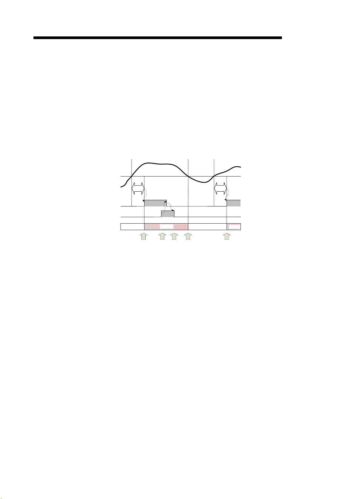
(2) Alarm flag (Xn1 to Xn8) and behavior of ALM1 LED and ALM2 LED
1) There are 4 statuses of alarm for each alarm monitoring element.
(a) Alarm non-occurrence status
(b) Alarm occurrence status
(c) Self-retention status (O n l y w hen the alarm reset method is set to “self-retention”)
(d) Alarm reset status
* In order to st ate the al arm , alar m monitoring must be les s tha n th e v al ue o nce during
Alarm value
Request of CH1 alarm reset (Yn1)
Alarm status
2) Relationship between the alarm status and Alarm flag (Xn1 to Xn8)
(a) Alarm non-occurrence status
(b) Alarm occurrence status
(c) Self-retention status
(d) Alarm reset status
QE82LG
The present value is under alarm value or the prese nt value exceeds alarm value but
the situation continues for less than alarm delay time.
The present value exceeds alarm value and the situation exceeds alarm delay time.
The present value has changed from the alarm oc currence status to be under alarm
value.
Alarm reset request (Yn1, Yn5) is released under the alarm occurrence status, and the
present value is sti ll over alarm value.
the alarm reset state.
non-occurrence
-occurrence
Figure 4.2.3-2 Example of alarm status (alarm reset method = “self-retention”)
Under the alarm non-occurrence status, Alarm flag (Xn1 to Xn8) is OFF.
Under the alarm occurrence status, Alarm flag (Xn1 to Xn8) is ON.
Under the self-retention status, Alarm flag (Xn1 to Xn8) is ON.
Under the alarm reset status, Alarm flag (Xn1 to Xn8) is OFF.
4 - 5
Page 24

4 Functions
QE82LG
3) Behaviors of ALM1 LED and ALM2 LED
(a) The indication of ALM1 LED changes according to status of CH1 Alarm.
Io1 primary alarm flag (Xn1)
Io1 secondary alarm flag (Xn2)
Ior1 primary alarm flag (Xn3)
Ior1 secondary alarm flag (Xn4)
(b) The indication of ALM2 LED changes according to status of CH2 Alarm.
Io2 primary alarm flag (Xn5)
Io2 secondary alarm flag (Xn6)
Ior2 primary alarm flag (Xn7)
Ior2 secondary alarm flag (Xn8)
(c) ALM1 LED and ALM2 LED disp lay the following 3 indications according to the alarm
status of the alarm occurrence flag.
- Flashing
Of the alarm occurrence f lags, one or m ore flags are in the alarm occurrenc e status
or in the alarm reset status (regardless of the status of the remaining alarm
occurrence flags).
- ON
Of the alarm occurrence f lags, one or m ore flags are in the self-retention status and
the remaining flags of alarm occurrence are in the alarm non-occurrence status.
- OFF
Flags of alarm occurrence are all in the alarm non-occurrence status.
4 - 6
Page 25
4 Functions
CH1漏洩電流一段警報
発生フラグ(Xn1)
OFF
ON
警報マスク時間
OFF
警報マスク時間
ALM1 LED
消灯 点滅
消灯
(a)
(b)
(c)
警報監視値
CH
1漏洩電流一段警報
発生フラグ(Xn1)
OFF
ON
警報マスク時間
ON
OFF
OFF
CH1警報リセット要求(Yn1)
OFF
ALM1 LED
消灯
点滅
消灯点灯
(a)
(b)
(c) (d)
警報監視値
Io1 primary alarm flag (Xn1)
OFF
Alarm mas k tim
Alarm mas k time
Flashing
OFF
Alarm mas k time
OFF
Flashing
ON
OFF
QE82LG
(3) Behavior of alarms
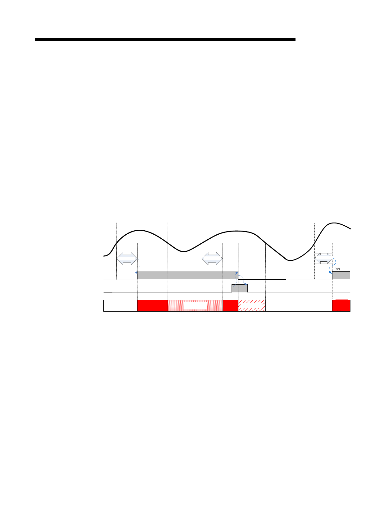
1) When the alarm reset m ethod is in the “aut o reset” s etting (Ex ample of Io1 primar y alarm
monitoring):
(a) If the present value Io1 exceeds alarm value and the situation continues for alarm
delay time, Io1 primary alarm flag (Xn1) will be turned ON. At th e same time, ALM1
LED flashes.
(b) If the present value goes below the upper limit, Io1 primar y alarm flag ( Xn1) will be
turned OFF. At this time, ALM1 LED is turned off.
(c) Even if the present value Io1 exceeds alarm value, if the value goes under alarm value
within alarm delay time, Io1 primary alarm flag (Xn1) will remain OFF.
Alarm value
e
Figure 4.2.3-3 Time chart of the secondary alarm (alarm reset method = “auto-reset”)
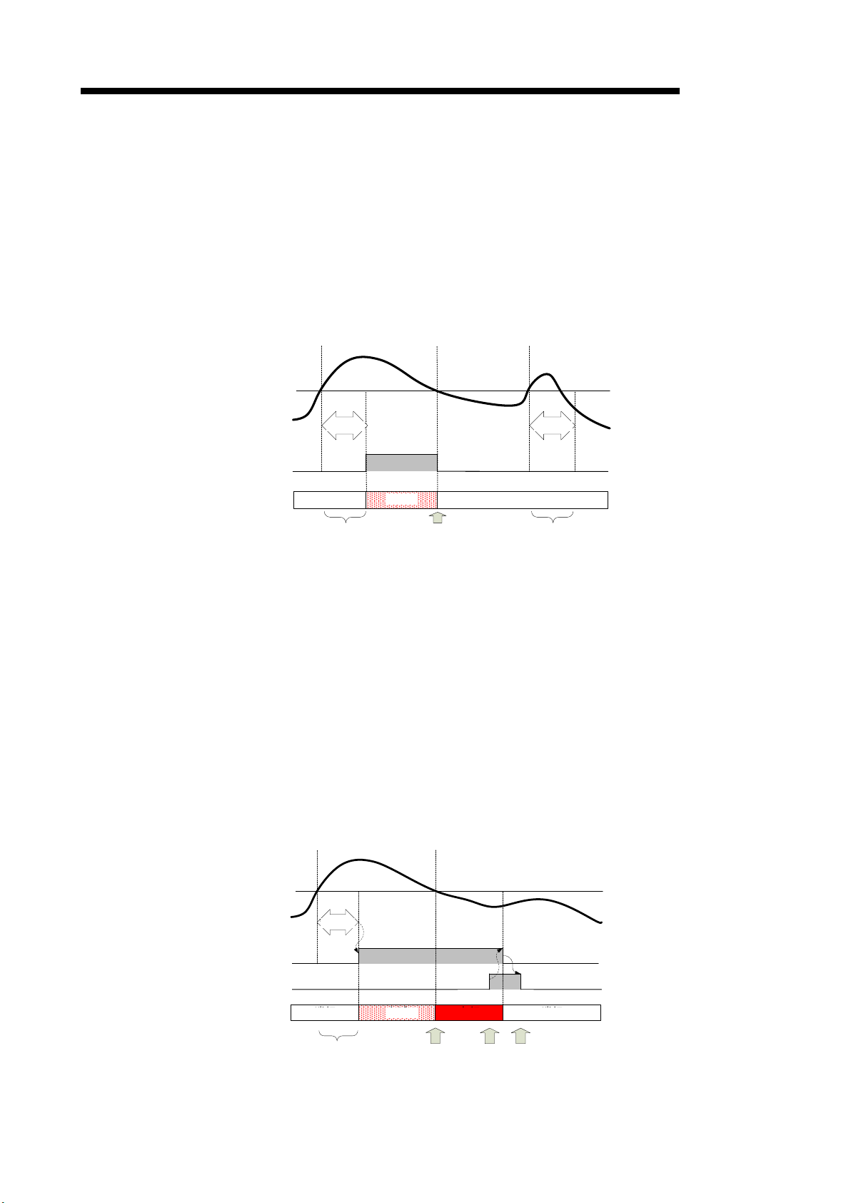
2) When alarm reset method is set to “self-retention” (Example of Io1 primary alarm
monitoring)
(a) If the present value Io1 exceeds alarm value and the situation continues for alarm
delay time, Io1 primary alarm flag (Xn1) will be turned ON. At th e same time, ALM1
LED flashes.
(b) If the present value Io1 goes below the upper limit, Io1 primary alarm flag (Xn1)
remains ON (self-retention). During the self-retention, ALM1 LED is turned on.
(c) By turning CH1 alarm res et request (Yn1) to ON, Io1 prim ary alarm flag (Xn1) will be
turned OFF. At this time, ALM1 LED is turned off.
(d) Check that Io1 pr im ary al arm flag (Xn1) becomes OFF, an d then s et CH1 alarm reset
request (Yn1) to OFF.
Alarm value
Io1 primary alarm flag (Xn1)
CH1 alarm reset request (Yn1)
Figure 4.2.3-4 Time chart of the secondary alarm (alarm reset method = “self-retention”)
4 - 7
Page 26

4 Functions
QE82LG
3) An example of Io1 primary alarm monitoring is indicated in 1) and 2) above. Other alarm
monitoring will be in accordance with the same behavior.
For the setting items for the buffer m emory that corres ponds to the alarm monitoring and
the I/O signals, refer to Chapters 5 and 6.
(3) How to reset Alarm flag
1) If Alarm flag is ON during the a larm occurrence or the self -retention (in the cas e of the
alarm reset method = “self -retention”), Alarm flag c an be reset (turned OFF) us ing Alarm
reset request.
2) CH1 alarm clear request (Yn1) wi ll clear the followin g data. However, the f ollowing data
cannot be cleared individually.
- Io1 primary alarm flag (Xn1)
- Io1 secondary alarm flag (Xn2)
- Ior1 primary alarm flag (Xn3)
- Ior1 secondary alarm flag (Xn4)
3) The following data can be cleared upon CH2 alarm reset request (Yn5). However, the
following data cannot be cleared individually.
- Io2 primary alarm flag (Xn5)
- Io2 secondary alarm flag (Xn6)
- Ior2 primary alarm flag (Xn7)
- Ior2 secondary alarm flag (Xn8)
4 - 8
Page 27
4 Functions
Io1一段警報発生フラグ
(Xn1)
OFF
ON
警報マスク
時間
ON
OFF
OFF
CH1警報リセット要求
(Yn1)
OFF
ALM1 LED
消灯
点滅 消灯
(b)
(c) (d)
(a)
点滅
(e)
警報マスク
時間
ON
警報監視値
Alarm
mask time
Alarm
mask time
OFF
Flashing
OFF
Flashing
QE82LG
4) How to reset Alarm flag during alarm occurrence (Example of Io1 primary alarm
monitoring)
(a) If the present value Io1 exceeds alarm value, Io1 primary alarm flag (Xn1) will be
turned ON. At the same time, ALM1 LED flashes.
(b) By turning CH1 alarm reset request (Yn1) to ON, Io1 prim ary alarm flag (Xn1) will be
turned OFF. At this time, ALM1 LED will remain flashing (because ALM1 LED is
synchronized with the alarm status, it will not turn off).
(c) Check that Io1 prim ar y alarm f lag (Xn1) becom es O FF, and then set CH1 al arm reset
request (Yn1) to OFF.
(d) If the present value Io1 goes under alarm value, ALM1 LED will be turned off.
(e) After that, if the present value Io1 exceeds alarm value, Io1 primar y alarm flag (Xn1)
will be turned ON again. At the same time, ALM1 LED flashes.
Alarm value
lo1 primary alarm flag (Xn1)
CH1 alarm reset request (Yn1)
5) How to reset Alarm flag during self-retention (in the case the alarm reset method =
“self-retention” only)
Refer to the procedure described in (2) 2).
Figure 4.2.3-5 Procedure for resetting Io1 primary alarm flag
(alarm reset method = “auto-reset”)
4 - 9
Page 28

4 Functions
CH1警報発生回数クリア要求(YnB)
CH1警報発生回数クリア完了フラグ(XnB)
ON
OFF
OFF
ON
OFF
OFF
CH1 alarm occurrence count clear completion flag (XnB)
4.2.4 Alarm occurrence count function
It memorizes the c ount of alarm occurrence f or each alarm monitoring e lement, and retains it
until the count of alarm occurrence is performed.
(1) Memory of Alarm occurrence count
1) It memorizes each alarm occurrence count for the following element.
- Io1 primary alarm
- Io1 secondary alarm
- Ior1 primary alarm
- Ior1 secondary alarm
- Io2 primary alarm
- Io2 secondary alarm
- Ior2 primary alarm
- Ior2 secondary alarm
2) Alarm occ urrence count is stored in the nonvolatile memory, so that it can be retaine d
even at a power source reset.
QE82LG
(2) How to clear Alarm occurrence count
1) You can use I/O signal to clear the count of alarm occurrence.
2) The count of alarm occurrence immediately after the clear will be “0”.
3) The following d ata can b e cleared upon C H1 a larm occ urrenc e co un t clear re ques t (YnB).
However, the following data cannot be cleared individually.
- Io1 primary alarm occurrence count (Un\G1200)
- Io1 secondary alarm occurrence count (Un\G1201)
- Ior1 primary alarm occurrence count (Un\G1250)
- Ior1 secondary alarm occurrence count (Un\G1251)
4) The following dat a can be c leared upon CH2 alar m occur renc e cou nt c lear req ues t (YnD).
However, the following data cannot be cleared individually.
- Io2 primary alarm occurrence count (Un\G2200)
- Io2 secondary alarm occurrence count (Un\G2201)
- Ior2 primary alarm occurrence count (Un\G2250)
- Ior2 secondary alarm occurrence count (Un\G2251)
5) The following describes how to clear CH1 alarm occurrence count. (CH2 alarm
occurrence count follows the same procedure using CH2 alarm occurrence count clear
request (YnD).)
(i) Check that CH1 alarm occurrence count clear request (YnB) is OFF.
(ii) Set CH1 alarm occurrence count clear request (YnB) to ON.
CH1 alarm occurrence count is cleared, and then CH 1 alarm occurrence cou nt clear
completion flag (XnB) is turned ON.
(iii) Check that CH1 alarm occurrenc e count clear completion fla g (XnB) is ON, and then
set CH1 alarm occurrence count clear request (YnB) to OFF.
CH1 alarm occurrence count clear request (YnB)
Figure 4.2.3-6 Procedure for clearing Alarm occurrence count
4 - 10
Page 29

4 Functions
4.2.5 Test function
This function is to output pseudo-fixed value to a buffer memory for debugging sequence
program. The value can be output to the buffer memory without input of voltage and current.
(1) How to use the test function
(2) Content of pseudo-output
QE82LG
1) Using the intelligent function switch sett ings, you can start the test mode to output the
fixed value.
2) For procedure for setting the intelligent function switch, refer to 7.5.2.
3) To finish the tes t mode, the set value is returned by th e intelli gent funct ion switch setting,
and after that, it starts a measuring m ode (low sensitivity mode or high sensitivity mode)
by resetting it.
(It resumes with the previous set value and accumulated electric energy as well as
periodic electric energy.)
For the value to be out put to the buff er memory, refer to Tables 6.1-1 to 6.1-3 in 6.1 Buffer
memory assignment.
(3) Percolations for using the test function
1) Because pseudo-f ixed value is output to the buff er memory, isolate the actual device to
avoid unexpected operation before running the sequence program.
4 - 11
Page 30
5 I/O signal to CPU unit
module)
QE82LG)
Device # Signal name
Device # Signal name
Xn0
Module ready
Yn0
Use prohibited *1
Xn1
Io1 primary alarm flag
Yn1
CH1 alarm reset request
Xn2
Io1 secondary alarm flag
Yn2
Use prohibited *1
Xn3
Ior1 primary alarm flag
Yn3
Use prohibited *1
Xn4
Ior1 secondary alarm flag
Yn4
Use prohibited *1
Xn5
Io2 primary alarm flag
Yn5
CH2 alarm reset request
Xn6
Io2 secondary alarm flag
Yn6
Use prohibited *1
Xn7
Ior2 primary alarm flag
Yn7
Use prohibited *1
Xn8
Ior2 secondary alarm flag
Yn8
Use prohibited *1
flag
XnA
CH1 max. value clear completion flag
YnA
CH1 max. value clear request
completion flag
request
XnC
CH2 max. value clear completion flag
YnC
CH2 max. value clear request
completion flag
request
XnE
Use prohibited *1
YnE
Use prohibited *1
XnF
Error flag
YnF
Error clear request
Chapter 5: I/O signal to CPU module
5.1 List of I/O signals
I/O signals of QE82LG are listed in Table 5.1-1.
The “n” that is us ed i n this and later ch apters (for example: Xn0, Yn0, Un\G0, etc.) refers to th e num ber
that appears at the beginning of QE82LG.
Table 5.1-1 List of I/O signals
Input signal (signal direction from QE82LG to CPU
Output signal(signal direction from CPU module to
QE82LG
Xn9
XnB
XnD
Operating condition setting completion
CH1 alarm occurrence count clear
CH2 alarm occurrence count clear
Yn9 Operating condition setting request
YnB
YnD
CH1 alarm occurrence count clear
CH2 alarm occurrence count clear
Point
*1 These signals cannot be used by the user since they are for system use
only. If these are set to on or off b y the sequence prog ram , the perf orm ance
of the QE82LG cannot be g uaranteed.
5 - 1
Page 31

5 I/O signal to CPU unit
5.2 Details of I/O signals
Detailed explanation about I/O signals of QE82LG is provided as follows:
5.2.1 Input signals
(1) Module ready (Xn0)
(a) When the po wer of CP U module is tur ned on or the CPU module reset is perf orm ed, it w ill
turn ON as soon as the measurement is ready.
(b) Module ready is turned OFF when the i nsulation monitoring module displa ys a hardware
error, and RUN LED is turned off.
(2) Io1 primary alarm flag (Xn1)
(a) When the present value Io1 exceeds Io1 primary alarm value (Un\G1000) and the
situation continues f or Io1 primary alarm delay time (Un\G1002), this sign al (Xn1) turns
ON.
(b) Operations after this s ignal ( X n1) is turned ON will be dif f er ent dep end ing on the s ettin g of
Io1 primary alarm reset method (Un\G1001) below.
[When Io1 primary alarm reset method (Un\G1001) is “self-retention”]
Even if the present value I o1 goes under Io1 prim ary alarm value (Un\G1000), th is signal
(Xn1) remains ON . Then, when CH1 alar m reset reques t (Yn1) is turned to ON, this s igna l
(Xn1) turns OFF.
QE82LG
[When Io1 primary alarm reset method (Un\G1001) is “auto reset”]
If the present value Io1 goes un der Io1 primar y alarm value (Un\G1000), this sig nal (X n1)
turns OFF.
(c) When Io1 pr imary alarm value (Un\G1000) is set to “0 (not m onitoring)”, this signal (Xn1)
is always OFF.
*For the actual behavior of alarm monitoring, refer to 4.2.4.
(3) Io1 secondary alarm flag (Xn2)
The usage procedure is the same as Io1 primary alarm flag (Xn1). Refer to (2).
(4) Ior1 primary alarm flag (Xn3)
The usage procedure is the same as Io1 primary alarm flag (Xn1). Refer to (2).
(5) Ior1 secondary alarm flag (Xn4)
The usage procedure is the same as Io1 primary alarm flag (Xn1). Refer to (2).
5 – 2
Page 32

5 I/O signal to CPU unit
QE82LG
(6) Io2 primary alarm flag (Xn5)
The usage procedure is the same as Io1 primary alarm flag (Xn1). Refer to (2).
(7) Io2 secondary alarm flag (Xn6)
The usage procedure is the same as Io1 primary alarm flag (Xn1). Refer to (2).
(8) Ior2 primary alarm flag (Xn7)
The usage procedure is the same as Io1 primary alarm flag (Xn1). Refer to (2).
(9) Ior2 secondary alarm flag (Xn8)
The usage procedure is the same as Io1 primary alarm flag (Xn1). Refer to (2).
(10) Operating condition setting completion flag (Xn9)
(a) When turning Operating c ondition settin g request (Yn9) to ON and c hanging the f ollowing
settings, this signal (Xn9) turns ON.
- Phase wire system (Un\G0)
- Io1 primary alarm value (Un\G1000)
- Io1 primary alarm reset method (Un\G1001)
- Io1 primary alarm delay time (Un\G1002)
- Io1 secondary alarm value (Un\G1003)
- Io1 secondary alarm reset method (Un\G1004)
- Io1 secondary alarm delay time (Un\G1005)
- Ior1 primary alarm value (Un\G1050)
- Ior1 primary alarm reset method (Un\G1051)
- Ior1 primary alarm delay time (Un\G1052)
- Ior1 secondary alarm value (Un\G1053)
- Ior1 secondary alarm reset method (Un\G1054)
- Ior1 secondary alarm delay time (Un\G1055)
- Io2 primary alarm value (Un\G2000)
- Io2 primary alarm reset method (Un\G2001)
- Io2 primary alarm delay time (Un\G2002)
- Io2 secondary alarm value (Un\G2003)
- Io2 secondary alarm reset method (Un\G2004)
- Io2 secondary alarm delay time (Un\G2005)
- Ior2 primary alarm value (Un\G2050)
- Ior2 primary alarm reset method (Un\G2051)
- Ior2 primary alarm delay time (Un\G2052)
- Ior2 secondary alarm value (Un\G2053)
- Ior2 secondary alarm reset method (Un\G2054)
- Ior2 secondary alarm delay time (Un\G2055)
(b) When Operating condition setting request (Yn9) is OFF, this signal (Xn9) turns OFF.
5 – 3
Page 33

5 I/O signal to CPU unit
QE82LG
(11) CH1 max. value clear completion flag (XnA)
(a) When CH1 max. value clear request (YnA) is turned ON and the following max. value data
are cleared, this signal (XnA) turns ON.
- Io1 max. value (Un\G1101)
- Io1 date/time of occurrence (Un\G1102 to Un\G1105)
- Ior1 max. value (Un\G1151)
- Ior1 date/time of occurrence (Un\G1152 to Un\G1155)
(b) When CH1 max. value clear request (YnA) is turned OFF, this signal (XnA) turns OFF.
(12) CH1 alarm occurrence count clear completion flag (XnB)
(a) When CH1 alarm occurrence count clear request (YnB) is turned ON and the f ollowing
alarm occurrence count data are cleared, this signal (XnB) turns ON.
- Io1 primary alarm occurrence count (Un\G1200)
- Io1 secondary alarm occurrence count (Un\G1201)
- Ior1 primary alarm occurrence count (Un\G1250)
- Ior1 secondary alarm occurrence count (Un\G1251)
(b) When CH1 a larm occurrence count clear req uest (YnB) is turn ed OFF, this signal (XnB)
turns OFF.
(13) CH2 max. value clear completion flag (XnC)
The usage proc edure is the same as C H1 max. value clear com pletion flag (XnA). Refer to
(11).
(14) CH2 alarm occurrence count clear completion flag (XnD)
The usage procedure is the same as CH1 alarm occurrence count clear completion flag (XnB).
Refer to (12).
(15) Error flag (XnF)
(a) If an outside-set-val ue err or oc curs , and if a har dware err or occ urs, this signa l (Xn F) turns
ON.
(b) The description of the error occurred can be checked with latest error code (Un\G3000).
*For description of error codes, refer to section 9.1.
(c) If an outside-set-value error occurs, this signal (XnF) is turned OFF by setting a value
within the range again.
5 – 4
Page 34

5 I/O signal to CPU unit
5.2.2 Output signals
(1) CH1 alarm reset request (Yn1)
(2) CH2 alarm reset request (Yn5)
QE82LG
(a) When resetting the following flags for alarm occurrence, this signal (Yn1) turns ON.
- Io1 primary alarm flag (Xn1)
- Io1 secondary alarm flag (Xn2)
- Ior1 primary alarm flag (Xn3)
- Ior1 secondary alarm flag (Xn4)
(b) When this signal (Yn1) is s witc he d f r om the OF F s tatus to the O N status, above alarm flag
will forcibly be turned OFF regardless of alarm flag status.
(a) When resetting the following flags for alarm occurrence, this signal (Yn5) turns ON.
- Io2 primary alarm flag (Xn5)
- Io2 secondary alarm flag (Xn6)
- Ior2 primary alarm flag (Xn7)
- Ior2 secondary alarm flag (Xn8)
(b) When this signal (Yn5) is switched f r om the O FF st atus to t he O N status, above alarm flag
will forcibly be turned OFF regardless of alarm flag status.
(3) Operating condition setting request (Yn9)
(a) When switching this signal (Yn9) from the OFF status to the ON status, the following
operating conditions will be set.
- Phase wire system (Un\G0)
- Io1 primary alarm value (Un\G1000)
- Io1 primary alarm reset method (Un\G1001)
- Io1 primary alarm delay time (Un\G1002)
- Io1 secondary alarm value (Un\G1003)
- Io1 secondary alarm reset method (Un\G1004)
- Io1 secondary alarm delay time (Un\G1005)
- Ior1 primary alarm value (Un\G1050)
- Ior1 primary alarm reset method (Un\G1051)
- Ior1 primary alarm delay time (Un\G1052)
- Ior1 secondary alarm value (Un\G1053)
- Ior1 secondary alarm reset method (Un\G1054)
- Ior1 secondary alarm delay time (Un\G1055)
- Io2 primary alarm value (Un\G2000)
- Io2 primary alarm reset method (Un\G2001)
- Io2 primary alarm delay time (Un\G2002)
- Io2 secondary alarm value (Un\G2003)
- Io2 secondary alarm reset method (Un\G2004)
- Io2 secondary alarm delay time (Un\G2005)
- Ior2 primary alarm value (Un\G2050)
- Ior2 primary alarm reset method (Un\G2051)
- Ior2 primary alarm delay time (Un\G2052)
- Ior2 secondary alarm value (Un\G2053)
- Ior2 secondary alarm reset method (Un\G2054)
- Ior2 secondary alarm delay time (Un\G2055)
5 – 5
Page 35

5 I/O signal to CPU unit
QE82LG
(b) When the operating con dition s etting is com pleted, Operating cond ition setting c om pletion
flag (Xn9) turns ON.
(c) When this signal (Yn9) is t urned OFF, Operating con dition setting completion fl ag (Xn9)
turns OFF.
(4) CH1 max. value clear request (YnA)
(a) When switching this s ig nal ( YnA) f rom the OFF status to th e O N s tat us , th e following max.
value date will be cleared.
- Io1 max. value (Un\G1101)
- Io1 date/time of occurrence (Un\G1102 to Un\G1105)
- Ior1 max. value (Un\G1151)
- Ior1 date/time of occurrence (Un\G1152 to Un\G1155)
(b) When clear ing the max. da ta above is com pleted, CH1 max. value clear completion fla g
(XnA) turns ON.
(c) When this signal (YnA) is turned OFF, CH1 max. value clear completion flag (XnA) is
turned OFF.
(5) CH1 alarm occurrence count clear request (YnB)
(a) When switching this s ig nal ( YnB) f rom the OFF status to t h e ON status, the follow ing max.
value data will be cleared.
- Io1 primary alarm occurrence count (Un\G1200)
- Io1 secondary alarm occurrence count (Un\G1201)
- Ior1 primary alarm occurrence count (Un\G1250)
- Ior1 secondary alarm occurrence count (Un\G1251)
(b) When clearing the max. data above is completed, CH1 alarm occurrence count clear
completion flag (XnB) turns ON.
(c) When this signal ( YnB) is tur ned OFF, C H1 alarm occurrence cou nt clear com pletion flag
(XnB) turns OFF.
(6) CH2 max. value clear request (YnC)
(a) When switching this s ig nal ( YnC) f r om the O FF st atus to the ON s tat us , the following max.
value data will be cleared.
- Io2 max. value (Un\G2101)
- Io2 date/time of occurrence (Un\G2102 to Un\G2105)
- Ior2 max. value (Un\G2151)
- Ior2 date/time of occurrence (Un\G2152 to Un\G2155)
(b) When clearing the max. data ab ove is completed, CH2 max. value clear completion fla g
(XnC) turns ON.
(c) When this signa l (YnC) is turned OFF , CH2 max. value c lear completion f lag (XnC) turns
OFF.
5 – 6
Page 36

5 I/O signal to CPU unit
QE82LG
(7) CH2 alarm occurrence count clear request (YnD)
(a) When switching this sig na l (YnD) f r om the O FF stat us to the O N s tat us , the following max.
value data will be cleared.
- Io2 primary alarm occurrence count (Un\G2200)
- Io2 secondary alarm occurrence count (Un\G2201)
- Ior2 primary alarm occurrence count (Un\G2250)
- Ior2 secondary alarm occurrence count (Un\G2251)
(b) When clearing the max. data above is completed, CH2 alarm occurrence count clear
completion flag (XnD) turns ON.
(c) When this sign al (YnD) is t urned OFF, CH2 alarm occurrence c ount clear com pletion flag
(XnD) turns OFF.
(8) Error clear request (YnF)
(a) When switching this signal from the OFF status to the ON status while an
outside-set-value error occurs, Error flag (XnF) will be turned OFF and latest error code
(Un\G3000) will be cleared.
(b) At the same time as the clearing error above, the value set in the buffer memory below will
be replaced with the previously set value.
[Values that are to be replaced with the previously set value]
- Phase wire system (Un\G0)
- Io1 primary alarm value (Un\G1000)
- Io1 primary alarm reset method (Un\G1001)
- Io1 primary alarm delay time (Un\G1002)
- Io1 secondary alarm value (Un\G1003)
- Io1 secondary alarm reset method (Un\G1004)
- Io1 secondary alarm delay time (Un\G1005)
- Ior1 primary alarm value (Un\G1050)
- Ior1 primary alarm reset method (Un\G1051)
- Ior1 primary alarm delay time (Un\G1052)
- Ior1 secondary alarm value (Un\G1053)
- Ior1 secondary alarm reset method (Un\G1054)
- Ior1 secondary alarm delay tim e (Un\G1055)
- Io2 primary alarm value (Un\G2000)
- Io2 primary alarm reset method (Un\G2001)
- Io2 primary alarm delay time (Un\G2002)
- Io2 secondary alarm value (Un\G2003)
- Io2 secondary alarm reset method (Un\G2004)
- Io2 secondary alarm delay time (Un\G2005)
- Ior2 primary alarm value (Un\G2050)
- Ior2 primary alarm reset method (Un\G2051)
- Ior2 primary alarm delay time (Un\G2052)
- Ior2 secondary alarm value (Un\G2053)
- Ior2 secondary alarm reset method (Un\G2054)
- Ior2 secondary alarm delay tim e (Un\G2055)
(c) While a hardware error is present (error code: 0000H to 0FFFH), it will not be cleared
even if this signal (YnF) turns ON.
5 – 7
Page 37

6 Buffer memory
QE82LG
Point
Address
(decimal)
Value during the
test mode*4
CH1
CH2
CH1
CH2
0
Pr
Phase wire system
3
R/W
3
1-99
-
System area
- - -
0
Leak current, Leak current for
(x 10n)
primary alarm
value
primary alarm
reset method
primary alarm
delay time
secondary
alarm value
secondary
method
secondary
time
1006-
1049
2006-
2049
primary alarm
value
primary alarm
reset method
primary alarm
delay time
secondary
alarm value
secondary
method
secondary
time
1056-
1100
2056-
2100
Chapter 6: Buffer memory
6.1 Buffer memory assignment
(1) Configurable sections (Un\G0 to Un\G1100, Un\G2000 to Un\G2100)
Table 6.1-1 Configurable sections (Un\G0 to Un\G1100, Un\G2000 to Un\G2100)
Item
The following describes buffer memory assignment.
Do not write dat a i nto the pr ohib ited area in the buff er memory from s ystem are a
and sequence program. If data are written into these areas, it may cause
malfunction.
Data
type*1
Description
Default
value
R/W*2
Backup
*3
○
Configur-
able
section
100 Md
1000 2000 Pr
1001 2001 Pr
1002 2002 Pr
1003 2003 Pr
1004 2004 Pr
1005 2005 Pr
1050 2050 Pr
1051 2051 Pr
1052 2052 Pr
1053 2053 Pr
1054 2054 Pr
1055 2055 Pr
resistance multiplying factor
Leak
current
alarm reset
alarm delay
- System area - - - - -
Leak
current for
resistance
alarm reset
alarm delay
0 R
0 R/W
0 R/W
0 R/W
0 R/W
0 R/W
0 R/W
0 R/W
0 R/W
0 R/W
0 R/W
0 R/W
0 R/W
○
○
○
○
○
○
○
○
○
○
○
○
○
-2
0 0
0 0
0 0
0 0
0 0
0 0
0 0
0 0
0 0
0 0
0 0
0 0
*1: Pr indicates setting data, and Md indicates monitoring data.
*2: It indicates readable / writable status from the sequence program.
*3: Even if the power failure is restored, data is held because data is backed up by the nonvolatile memory.
*4: For the procedure for using the test mode, refer to section 4.2.5.
- System area - - - - -
R: Readable
W: Writable
6 – 1
Page 38

6 Buffer memory
QE82LG
Address
(decimal)
Value during the
test mode*4
CH1
CH2
CH1
CH2
1100
2100
Md
Leak
Present value
0 R -
1001
2001
1101
2101
Md
Max. value
0
R
1002
2002
Year of time of
max. value
Month and day
value
Hour and minute
value
Second and day
value
1106-
1149
2106-
2149
System area
1150
2150
Md
Leak
Present value
0 R -
1011
2011
1151
2151
Md
Max. value
0
R
1012
2012
Year of time of
max. value
Month and day
value
Hour and minute
value
Second and day
value
1156-
1199
2156-
2199
System area
Leak
primary alarm
count
secondary alarm
count
1202-
1249
2202-
2249
System area
Leak
primary alarm
count
secondary alarm
count
1252-
1999
2252-
2999
System area
(2) Measurable sections (Un\G1100 to Un\G1999, Un\G2100 to Un\G2999)
Table 6.1-2 Measurable sections (Un\G1100 to Un\G1999, Un\G2100 to Un\G2999)
Item
Data
type*1
Description
Default
value
R/W*2
Backup
*3
Measurable
section
1102 2102 Md
1103 2103 Md
1104 2104 Md
1105 2105 Md
-
1152 2152 Md
1153 2153 Md
1154 2154 Md
1155 2155 Md
-
current
current for
resistance
of time of max.
of time of max.
of the week of
time of max.
of time of max.
of time of max.
of the week of
time of max.
○
0000h R
0000h R
0000h R
0000h R
- - - - -
0000h R
0000h R
0000h R
0000h R
- - - - -
○
○
○
○
○
○
○
○
○
2010h 2020h
0903h 1004h
0102h 0203h
0304h 0405h
2011h 2021h
0102h 0203h
0304h 0405h
0506h 0600h
1200 2200 Md
1201 2201 Md
-
1250 2250 Md
1251 2251 Md
-
current
current for
resistance
occurrence
occurrence
occurrence
occurrence
0 R
0 R
- - - - -
0 R
0 R
- - - - -
○
○
○
○
1021 2021
1022 2022
1031 2031
1032 2032
*1: Pr indicates setting data, and Md indicates monitoring data.
*2: It indicates readable / writable status from the sequence program.
R: Readable
W: Writable
*3: Even if the power failure is restored, data is held because data is backed up by the nonvolatile memory.
*4: For the procedure for using the test mode, refer to section 4.2.5.
6 – 2
Page 39

6 Buffer memory
QE82LG
3000
Md
Latest error code
0000h R -
0001h
3001
Md
Year of time of error
0000h R -
2019h
3002
Md
Month and day of time of error
0000h R -
0910h
3003
Md
Hour and minute of time of error
0000h R -
1112h
3004
Md
Month and day of time of error
0000h R -
1301h
3005-3499
-
System area
- - - - 3500
Md
Measuring mode
0000h R -
0001h
3501-4999
-
System area
- - -
-
(3) Common sections (Un\G3000 to Un\G4999)
Table 6.1-3 Latest error sections (Un\G3000 to Un\G4999)
Item
Common
sections
Address
(decimal)
Data
type*1
Description
Default
value
R/W*2
Backup
*3
Value during the
test mode*4
*1: Pr indicates setting data, and Md indicates monitoring data.
*2: It indicates readable / writable status from the sequence program.
R: Readable
W: Writable
*3: Even if the power failure is restored, data is held because data is backed up by the nonvolatile memory.
*4: For the procedure for using the test mode, refer to section 4.2.5.
6 – 3
Page 40

6 Buffer memory
QE82LG
Setting v alue
Description
1
Single-phase 2-wire
2
Single-phase 3-wire
3
Three-phase 3-wire
Setting ran ge
Description
0
No monitoring
High sensitivity mode: 1 to 10000 (
mA)
6.2 Configurable sections (Un\G0 to Un\G1100, Un\G2000 to Un\G2100)
6.2.1 Phase wire system (Un\G0)
Phase wire system for target electric circuits is configured.
It is common for both CH1 and CH2.
(1) Setting procedure
(a) Set the phase wire in the buffer memory. Setting range is as follows:
(b) Turn Operatin g condition setting reques t ( Yn9) from OFF to ON to enable the s etting. (Ref er to
5.2.2(5).)
(2) Defaul t val ue
It is set to 3 (Three-phase 3-wire).
6.2.2 Leak current, Leak current for resistance multiplying factor (Un\G100)
Stores the measured value of multiplying factor for leak current and leak current for resistance.
(1) Details of stored data
(a) It dep en d s on t he measuring mode (low sensitivity mode and high sensitivity mode).
For the setting of Measuring mode, refer to section 7.6.2 or 7.7.2.
(2) Defaul t val ue
0
It is set to 0. (Low sensitivity mode: 10
)
6.2.3 Io1 primary alarm value (Un\G1000)
Set the monitoring level of CH1 leak current.
For the buffer memory address of other monitoring value, refer to section 6.1(1).
(1) Setting procedure
(a) Set the monitoring value in the buffer memory. Setting range is as follows:
(b) Turn Operating c ondition setting re quest (Yn9) from OFF to ON to enable the setting. ( Refer to
(2) Defaul t val ue
All monitoring values are set to 0 (no monitoring).
Low sensitivity mode: 1 to 1000 (mA)
5.2.2(5).)
-2
×
6 – 4
Monitors with the set value
Page 41

6 Buffer memory
QE82LG
Setting v alue
Description
0
Self-retention
1
Auto reset
6.2.4 Io1 primary alarm reset method (Un\G1001)
Set alarm reset method of CH1 leak current.
For differences in behavior of alarm monitoring for different reset methods, refer to 4.2.4(2).
For the buffer memory address of other reset methods, refer to section 6.1(1).
(1) Setting procedure
(a) Set the reset method in the buffer memory. Setting range is as follows:
(b) Turn Operating c ondition setting re quest (Yn9) from OFF to ON to enable the setting. ( Refer to
5.2.2(5).)
(2) Defaul t val ue
All reset methods are set to 0 (self-retention).
6.2.5 Io1 primary alarm delay time (Un\G1002)
Set alarm delay time of CH1 leak current.
Alarm dela y time means a gr ace period of tim e that starts from the moment when it exceeds the upper
limit of monitoring value until the alarm occurrence flag is turned ON. For detailed behavior, refer to
4.2.4(2).
For the buffer memory address of other alarm delay time, refer to section 6.1(1).
(1) Setting procedure
(a) Set alarm delay time in the buffer memory.
- Configurable range: 0 to 300 (seconds)
- Set the value in seconds.
(b) Turn Operating condition setting request (Yn9) from OFF to O to enable the setting. (Refer to
5.2.2(5).)
(2) Defaul t val ue
All alarm delay time is set to 0 (seconds).
6 – 5
Page 42

6 Buffer memory
QE82LG
Un¥G100)
-2
×10-2mA
0
×100mA
6.3 Measurable sections (Un\G1100 to Un\G1999, Un\G2100 to Un\G2999)
This product divides the measuring data into the Data and Multiplier, and output them to Buffer memory.
Actual measuring data is obtained by the following formula.
n
Measuring data = Data × 10
(Multiplier is n).
(Example)
The values output to the Buffer memory are as follows when lo present value is measured 123.45mA.
Data (Un\G1100): 12345
Multiplier (Un\G100): -2 (High sensitive mode)
The actual measuring data is obtained from the value of Buffer memory as follows.
Measuring data = 12345 × 10
-2
= 123.45mA
6.3.1 Io1 present value (Un\G1100)
Stores the measured value of CH1 leak current.
For the buffer memory address of CH2, refer to section 6.1(2).
(1) Details of stored data
(a) Storage format
Data are stored as 16-bit unsigned binary in the buffer memory.
- Data range: Low sensitivity mode: 0 to 9999 (mA), High sensitivity mode: 0 to 65535(x 10
*Restrictions for measured data including resolution and measuring range, refer to section 4.2.1.
-2
mA)
(b) Unit
It is decided by leak current, leak current for resistance multiplying factor. (Un¥G100)
Leak current, Leak current for resistance multiplying factor
(
Unit
(c) Data update cycle
It will be updated approximately every 2 seconds.
6 – 6
Page 43

6 Buffer memory
QE82LG
6.3.2 Io1 max. value (Un¥G1101)
Stores the max. value of Io1 present value.
For the buffer memory address of CH2, refer to section 6.1(2).
(1) Details of stored data
(a) Storage format
Data are stored as 16-bit unsigned binary in the buffer memory.
- Data range: Low sensitivity mode: 0 to 9999 (mA), High sensitivity mode: 0 to 65535(x 10
*Restrictions for measured data including resolution and measuring range, refer to section 4.2.1.
(b) Data update cycle
It will be updated according to the update cycle of Io1 present value (Un\G1100).
(2) How to clear the stored data
To clear all of CH1 max. values, perform the following operations.
- Change CH1 max. value clear request (YnA) from OFF to ON.
After stored data are cleare d, the max. values that have been obtained since all data were cleared
will be stored for every CH1 max. value.
*To clear CH2 max. values, follow the same procedure using CH2 max. value clear request (YnC).
-2
mA)
6 – 7
Page 44

6 Buffer memory
QE82LG
Buffer memory address
Storage format
b15 b12 b11 b8 b7 b4 b3 b0
~
~
~
~
b15 b12 b11 b8 b7 b4 b3 b0
~
~
~
~
Day
b15 b12
b11 b8
b7
b4 b3
b0
~
~
~
~
b15 b12 b11 b8 b7 b4 b3 b0
~
~
~
~
0 日
1 月
2 火
3 水
4 木
5 金
6 土
曜日
Day of the week
0
Sunday
1
Monday
2
Tuesday
3
Wednesday
4
Thursday
5
Friday 6 Saturday
6.3.3 Year of time of Io1 max. value (Un\G1102), Month and day of time of Io1 max. value (Un\G1103),
Hour and minute of time of Io1 max. value (Un\G1104),
Second and day of the week of time of Io1 max. value (Un\G1105)
Stores the occurrence dat e/time such as year, m onth, da y, hour, minu te, second, an d day of th e week of
Io1 max. value (Un\G1101).
For the buffer memory address of CH2, refer to section 6.1(2).
(1) Details of stored data
(a) Storage format
As indicated below, data are stored as BCD code in the buffer memory.
e.g.) Year 2011
Un\G1102
2011h
Year
Un\G1103
Un\G1104
Un\G1105
Month
Hour
Second
e.g.) Jan 21
0121h
e.g.) 10:35
1035h
Minute
e.g.) 48sec Friday
4805h
0 fixed
(b) Data update cycle
It will be updated according to the update cycle of Io1 present value (Un\G1100).
(2) How to clear the stored data
To clear all of CH1 max. value occurrence dates, perform the following operations.
- Change CH1 max. value clear request (YnA) from OFF to ON.
After stored data are c leare d, the max. valu e occur renc e dates that hav e been obt ained since all data
were cleared will be stored for every CH1 max. value occurrence date.
*To clear CH2 max. values, follow the same procedure using CH2 max. value clear request (YnC).
6 – 8
Page 45

6 Buffer memory
QE82LG
6.3.4 Ior1 present value (Un\G1150)
Stores the measured value of CH1 leak current for resistance.
For the buffer memory address of CH2, refer to section 6.1(2).
(1) Details of stored data
(a) Storage format
Data are stored as 16-bit unsigned binary in the buffer memory.
- Data range: Low sensitivity mode: 0 to 9999 (mA), High sensitivity mode; 0 to 65535 (x10
*Restrictions for measured data including resolution and measuring range, refer to section 4.2.1.
(b) Data update cycle
It will be updated approximately every 10 seconds.
6.3.5 Ior1 max. value (Un\G1151)
Stores the max. value of Ior1 present value.
For the buffer memory address of CH2, refer to section 6.1(2).
(1) Details of stored data
-2
mA)
(a) Storage format
Data are stored as 16-bit unsigned binary in the buffer memory.
-2
- Data range: Low sensitivity mode: 0 to 9999 (mA), High sensitivity mode; 0 to 65535 (x10
mA)
*Restrictions for measured data including resolution and measuring range, refer to section 4.2.1.
(b) Data update cycle
It will be updated according to the update cycle of Ior1 present value (Un\G1150).
(2) How to clear the stored data
To clear all of CH1 max. values, perform the following operations.
- Change CH1 max. value clear request (YnA) from OFF to ON.
After stored data ar e cle are d, th e max. val ues that have be en obtai ned since all data w ere clear ed will
be stored for every CH1 max. value.
*To clear CH2 max. values, follow the same procedure using CH2 max. value clear request (YnC).
6 – 9
Page 46

6 Buffer memory
QE82LG
Buffer memory address
Storage format
b15 b12 b11 b8 b7 b4 b3 b0
~
~
~
~
b15 b12 b11 b8 b7 b4 b3 b0
~
~
~
~
Day
b15 b12
b11 b8
b7
b4 b3
b0
~
~
~
~
b15 b12 b11 b8 b7 b4 b3 b0
~
~
~
~
0 日
1 月
2 火
3 水
4 木
5 金
6 土
曜日
Day of the week
0
Sunday
1
Monday
2
Tuesday
3
Wednesday
4
Thursday
5
Friday
6
Saturday
6.3.6 Year of time of Ior1 max. value (Un\G1152), Month and day of time of Ior1 max. value (Un\G1153),
Hour and minute of time of Ior1 max. value (Un\G1154),
Second and day of the week of time of Ior1 max. value (Un\G1155)
Stores t he occurrence dat e/time such as year, m onth, da y, hour, minu te, second, an d day of th e week of
Ior1 max. value (Un\G1151).
For the buffer memory address of CH2, refer to section 6.1(2).
(1) Details of stored data
(a) Storage format
As indicated below, data are stored as BCD code in the buffer memory.
e.g.) Year 2011
Un\G1152
2011h
Year
Un\G1153
Un\G1154
Un\G1155
Mont
Hour
Sec
e.g.) Jan 21
0121h
e.g.) 10:35
1035h
Minute
e.g.) 48sec Friday
4805h
0 fixed
(b) Data update cycle
It will be updated according to the update cycle of Ior1 present value (Un\G1150).
(2) How to clear the stored data
To clear all of CH1 max. value occurrence dates, perform the following operations.
- Change CH1 max. value clear request (YnA) from OFF to ON.
After stored data are c leare d, the max. valu e occur renc e dates that hav e been obt ained since all data
were cleared will be stored for every CH1 max. value occurrence date.
*To clear CH2 max. values, follow the same procedure using CH2 max. value clear request (YnC).
6 – 10
Page 47

6 Buffer memory
QE82LG
6.3.7 Io1 primary alarm occurrence count (Un\G1200)
Stores the co unt of alarms that occurred with Io1 prim ary alarm (how m any times Io1 pr imary alarm flag
(Xn1) has been turned ON).
For the buffer memory address of other alarm occurrence count, refer to section 6.1(2).
(1) Details of stored data
(a) Storage format
Data are stored as 16-bit signed binary in the buffer memory.
- Data range: 0 to 9999 (times)
(b) Data update cycle
It will be updated according to the update cycle of Io1 present value (Un\G1100).
(2) How to clear the stored data
To clear all of CH1 alarm occurrence count, perform the following operations.
- Change CH1 alarm occurrence count clear request (YnB) from OFF to ON.
After stored data are cleared, “0” will be stored for all CH1 alarm occurrence counts.
*To clear CH2 alarm occurr ence cou nt, fol low the sam e proce dure us ing CH2 alarm oc currenc e count
clear request (YnD).
6 – 11
Page 48

6 Buffer memory
QE82LG
6.4 Common sections (Un\G3000 to Un\G4999)
6.4.1 Latest error code (Un\G3000)
*For the list of error codes, refer to section 9.1.
(1) Details of stored data
(a) Storage format
Data are stored as 16-bit unsigned binary in the buffer memory.
- Data range: 0000h (normal), 0001h to FFFFh (error code)
(b) Data update cycle
It will be updated at the time of error occurrence and error recovery.
6 – 12
Page 49

6 Buffer memory
QE82LG
Buffer memory address
Storage format
Measuring mode
Measuring mode(Un¥G3500)
Low sensitivity mode
High sensitivity mode
b15 b12 b11 b8 b7 b4 b3 b0
~
~
~
~
b15 b12 b11 b8 b7 b4 b3 b0
~
~
~
~
Month
b15
b12
b11 b8
b7 b4 b3 b0
~
~
~
~
b15 b12 b11
b8 b7 b4 b3 b0
~
~
~
~
0 日
1 月
2 火
3 水
4 木
5 金
6 土
曜日
Day of the week
0
Sunday
1
Monday
2
Tuesday
3
Wednesday
4
Thursday
5
Friday 6 Saturday
6.4.2 Year of time of error (Un\G3001), Month and day of time of error (Un\G3002),
Hour and minute of time of error (Un\G3003),
Second and day of the week of time of error (Un\G3004)
Stores the occurrence dat e/time such as year, m onth, da y, hour, minu te, second, an d day of th e week of
the error.
(1) Details of stored data
(a) Storage format
As indicated below, data are stored as BCD code in the buffer memory.
Un\G3001
Year
Un\G3002
Day
e.g.) Year 2011
2011h
e.g.) Jan 21
0121h
(b) Data update cycle
It will be updated at the time of error occurrence and error recovery.
6.4.3 Measuring mode (Un\G3500)
The setting content for measuring mode can be checked.
For the setting of Measuring mode, refer to section 7.6.2 or 7.7.2.
Un\G3003
Un\G3004
Hour
Second
e.g.) 10:35
1035h
Minute
e.g.) 48 sec Friday
4805h
0 fixed
0
1
6 – 13
Page 50

7 Setting and procedure for oper ati on
QE82LG
Locations of screws
Torque range
Module-fixing screws (M3 screw) *1
0.36 - 0.48 N•m
Chapter 7: Setting and proc edur e for oper ati on
7.1 Precautions for handling
(1) Do not drop the case of this module or give a strong impact.
(2) Do not remove the printed circuit board of the module from the case.
It may cause failure.
(3) Prevent the inside of the module from any foreign objects such as chips and wire pieces.
It may cause fire, failure or malfunction.
(4) In order to prevent the module from incoming foreign objects such as wire pieces during wiring
work, a foreign-object preventive label is placed on the module.
While a wiring work is performed, keep the label on the module.
Before operating the system, peel off the label for heat release.
(5) Module fixing screws must be tightened within the specified range as described below.
Loose screws may cause short-circuit, failure, or malfunction.
*1 The module can be fixed easily to the base unit, using the hook on top of the module. However,
if it is used under a vibrating environment, we strongly recommend that the module be fixed with
screws.
Table 7.1-1 Tightening torque
(6) To attach the module to the base unit, firmly insert the protruding portions for fixing the module into
the holes on the base unit, and make sure the module is securely attached to the module holes as
fulcrum points.
Insecure attachment of the module may case malfunction, failure, and a falling.
(7) Before touching the module, make sure that you need to discharge static electricity on your body by
touching a metal that is grounded.
Otherwise, it may cause failure or malfunction to the module.
7 - 1
Page 51

7 Setting and procedure for oper ati on
QE82LG
Start
(Refer to 7.4.)
Setting the in telligent function of module switch
7.2 Procedure for operation
Attaching the module
Attach QE82LG to the specified base unit.
Wiring
Wire QE82LG for external device. (Refer to 7.5.)
Initial setting
Perform settings using GX Works2. (Refer to 7.6.)
Perform settings using GX Developer. (Refer to 7.7.)
Programming, debugging,
Create and check the sequence program.
Figure 7.2-1 Procedure for operation
7 - 2
Page 52

7 Setting and procedure for oper ati on
QE82LG
(1)LED
7.3 Name and function of each part
Names and functions of parts of QE82LG are provided below.
(3) Push button
Use this button to
insert a cable to the
terminal or to remove
them.
(4) Check hole
Use this for continuity
check to the terminal.
Use it with a tester
contact.
Figure 7.3-1 Appearance of the module
Operation status of this
module is displayed.
(Refer to 7-4.)
(2) Input terminals
Voltage wire and leak current
wire of the measuring circuit
(dedicated ZCT secondary
output) are connected.
(5) Strip gauge
A gauge that is used for
checking the length of
stripped wire.
7 - 3
Page 53

7 Setting and procedure for oper ati on
QE82LG
Displays the
of this module.
ON: Normal operation
timer error
P1
1-phase voltage input terminal
(1) Names and functions of LEDs
The following describes names and functions of LEDs.
Table 7.3-1 Names and functions of LEDs
Name
RUN LED Green
Color
Role
operation status
Displays errors
ERR. LED Red
and conditions of
this module.
Displays ala r m
ALM1 LED Red
occurrence status
of CH1.
Displays ala r m
ALM2 LED Red
occurrence status
of CH2.
Note: During the test (debug), all LEDs will be turned ON.
*1 For details, check with the list of error codes. (Refer to section 9.1.)
(2) Names of signals of terminal block
The following describes names of signals of terminal block.
Table 7.3-2 Names of signals of terminal block
ON/OFF condition
OFF: 5V power discontinuity, watch dog
*1
ON: Hardware error
Flashing: Out-of-range error
OFF: Normal operation
Refer to 4.2.3 (2) 3).
Refer to 4.2.3 (2) 3).
*1
Name of terminal
CH1 Z+, Z Leak current input terminal (CH1)
CH1 Z+, Z Leak current input terminal (CH2)
P2
P3
FG Frame GND terminal
2-phase voltage input terminal
3-phase voltage input terminal
Description
7 - 4
Page 54

7 Setting and procedure for oper ati on
QE82LG
Caution
, tighten the module to the
Locations of screws
Torque range
Module-fixing screws (M3 screw)
*1
0.36 - 0.48 N•m
be perform ed 50 tim es or less
(to conform to JIS B3502). If the count exceeds 50 times, it may cause a malfunction.
Insert it securely so that the
protruding portion for fixing the
modul
does not come off of
the
Push the module toward the
arrow direction, as the
module-fixing hole being a
fulcrum point, until you hear a
click sound to firmly attach it to
the base unit.
Check that the module is firmly
inserted to the base unit.
Complete
Base unit
Module
Hole for fixing the
module
Hook for fixing the
module (*2)
Module connector
Base unit
Protrusion for fixing
the
Lever for attaching
the
Hole for fixing the
module
Protrusion for fixing
the
Lever for attaching
the
7.4 Attaching and removing the module
7.4.1 How to attach to the base un i t
e*1
module-fixing hole.
module (*1)
module
Base unit
module
module
Attach to the base of MELSEC-Q series.
•
When attaching t he modul e, mak e sure to inser t the prot ruding por tions for f ixing t he module
•
into the holes on the base un it. I n doing s o, i nsert it se curel y so th at the protru ding portion of
the module does not c ome off of th e holes . Do n ot force to att ach the m odule; other wise the
module may break.
When installing the module at a vibrating area w ith strong impact
•
base unit using screws. Module-fixing screws: M3 x 12 (Prepare them yourself.)
Attaching and detachi ng the m odule a nd the b ase unit s hould
•
7 - 5
Page 55

7 Setting and procedure for oper ati on
QE82LG
Module
connector
Hook for fixing
the
Hole for fixing the
module
Base unit
Module
Push
Lift it up
Complete
Hold the module with both hand,
While pushing the hook for fixing
fulcrum point.
As lifting the module upward,
7.4.2 How to detach the base un it
and push the hook for fixing the
*1
module
located on top of the
module until it stops.
the module*1, pull the module
straight toward yourself using the
lower part of the module as a
release the protruding portion for
fixing the module*2 from the hole.
When module-fixing screws are used, make sure to remove the screws for detaching the
•
module first, and then remove the protruding portion for fixing the module from the holes. Do no
force to remove the module; it may break the protruding portions for fixing the module.
module (*1)
7 - 6
Page 56

7 Setting and procedure for oper ati on
QE82LG
P1, P2, P3, FG
Stranded wire: AWG22 – AWG18 (0.3 – 0.8 mm2)
Z+, Z
Stranded wire: AWG22 – AWG18 (0.3 – 0.8 mm2)
Recommended bar terminal
TGV TC-1.25-11T (Made by Nichifu) or equivalent
Stripping length of the wir e
7.5 Connecting wires, wiring
7.5.1 Precautions for wiring
(1) Connect cables. For connecting voltage transformer and ZCT, refer to the wiring
diagram.
(2) For wiring, check with the wiring diagram and check the phase wire system for the
connecting circuit.
(3) For the leak current input, Mitsubishi's ZCT is required. (Refer to section 7.5.3.)
(4) If a current sensor is located in a strong m agnetic f ield s uch area n earb y a trans for m er
or high-current cable bus bar, the voltage circuit inpu t m ay be influenc ed, whic h i n turn
affects the measured value. Thus, please ensure sufficient distance between devices.
(5) For wiring voltage circuit and ZCT secondar y, use separate cables from other externa l
signals in order to prevent from AC surge and induction.
(6) Keep any object off the cables.
(7) Protect cable coating from scratch.
7.5.2 How to connect wires
(1) Follow the wiring diagram for external connection to QE82LG.
(2) Use appropriate electric wires as described below.
Appropriate wires for voltage input circuit (acceptable electric wires)
Voltage input terminal
Single wire: AWG24 – AWG18 (φ0.5 - 1.0mm)
Appropriate wires for leak current input (acceptable electric wires)
Leak current input terminal
(3) Stripping length of the wire in use has to be 10 to 11 mm. C heck the stripping length
using the strip gauge of this module.
(4) When using stranded wire, make sure to use a bar terminal or treat the wire ed ge by
stripping in order to keep thin lines from loosening.
* Stranded wire
(5) When attaching and detaching cables to/from the terminal, use the push butto n. Check
that the wire is securely inserted.
(6) Insert a wire to the terminal all the way until it touches the end.
Single wire: AWG24 – AWG18 (0.5 – 1.0 mm2)
10 to 11 mm
7 - 7
Page 57

7 Setting and procedure for oper ati on
QE82LG
QE
82LG
Z
+
Z
Z
+
Z
P1
P
2
P
3
FG
C
H
1
C
H
2
1
2
3
負荷1
負荷
2
零相変流器
(
ZCT
)
QE82
LG
Z+
Z
Z
+
Z
P1
P2
P3
FG
C
H
1
C
H
2
1(1
)
2
(0)
3(
2)
負荷1 負荷2
零相変流器
(ZCT)
Zero-phase current
Power
source
side
Load
7.5.3 Connection diagram
For external connection to QE82LG, follow the phase method and the connection diagram.
Power
source
side
side
transformer
(ZCT)
Load 1 Load 2
Figure 7.5.3-1 In the case of Three-phase 3-wire
Load
side
Zero-phase current
transformer
(ZCT)
Load 1 Load 2
Figure 7.5.3-2 In the case of Single-phase 3-wire
7 - 8
Page 58

7 Setting and procedure for oper ati on
QE82LG
QE82LG
Z+
Z
Z+
Z
P1
P2
P3
FG
C
H
1
C
H
2
1(1)
2(0)
負荷
1 負荷2
零相変流器
(ZCT)
QE82LG
Z+
Z
Z+
Z
P1
P2
P3
FG
C
H
1
C
H
2
1
2
3
負荷1 負荷2
零相変流器
(ZCT)
Power
source
side
Load
Zero-phase current
Load
side
transformer
(ZCT)
Load 1 Load 2
Figure 7.5.3-3 In the case of Single-phase 2-wire
Power
source
side
(with the voltage transformer for gauge/current transformer)
Load 1 Load 2
Figure 7.5.3-3 In the case of Single-phase 2-wire
7 - 9
side
Zero-phase current
transformer
(ZCT)
Page 59

7 Setting and procedure for oper ati on
QE82LG
Transformer
Load side
Zero-phase current
1 2 3
transformer
(ZCT)
Figure 7.5.3-5 Measuring with the transformer secondary side ground line
- ZCT (CZ, ZT series) do not have a secondary output polarity .
- ZCT(CZ, ZT series) are dedicated for low voltage circuits. It cannot be used for high voltage circuits. Connecting
to a high voltage circuit by mistake can cause burning of equ ip ment and fir e, which is extremely dangerous.
- In the absence of voltage input, correct measurement cannot be performed, so be sure to connect the voltage
input terminal.
- Two circuits can be measured by one module at sa me lin e an d same pha se wire system.
(ex. It cannot be measured when CH1: three-phase 3-wire, CH2: single-phas e 3-wire)
- Measuring of the leakage current for resistance can be measured with single-phase 2-wire, single-phase 3-wire,
three-phase 3-wire delta circuit.
- Measuring of the leakage current (Io) can be measured with three-phase 3-wire star circuit and special grounding
circuit such as high resistance grounding circuit and capacitor gr ounding circuit..
7 - 10
Page 60

7 Setting and procedure for oper ati on
QE82LG
Mitsubishi ZCT
ZCT
Do not pass a dedicated
module.
7.5.3.1 Connection to leak current circuit (Z+, Z terminal)
For wiring the leak current circuit, use Mitsubishi’s zero-phase current transformer (ZCT).
*Using other company’s zero-phase current transformer (ZCT) is not allowed.
(1) Combination of zero-phase current transformers (ZCT)
For ZCT combination, use Mitsubishi’s device as des cribed below.
Split-type ZCT CZ-22S, CZ-30S, CZ-55S, CZ-77S, CZ-112S
Through-type
ZCT with primary
conductor
ZT15B, ZT30B, ZT40B, ZT60B, ZT80B, ZT100B
(2) Length of wire between ZC T and this module is max. 50 m (when used with the appr opriate
cable in section 7.5.2).
(3) ZCT output wire from Z+ and Z terminal has to be stranded at 40 times/m.
Supplemental: ZCT connection
(1) Precautions for passing a conductor through the ZCT
1. In the case of the
Single-phase 3-wire type,
make sure to pass all three
wires, including a neutral
wire, through ZCT.
2. If a ground line is connected
to the cable run, do not let it
go through the ZCT. (If load
current flow is not intended,
do not use the wire for
passing through ZCT. )
Neutral conductor to ZCT
ground line through the
ZTA600A, ZTA1200A, ZTA2000A
3. If an accident such as short
circuit occurs, and large
current that exceeds the
rating flows through the
wire, it may cause
mechanical stress to the
ZCT. Thus, tie the wires
together using a tightening
band, etc.
4. Do not bend the passing wire near ZCT. If you use a primary
conductor over 300 A, keep one side of the wire at 30 cm or
longer.
30 cm or longer
5. Do not use a ZCT lead wire
for ground.
7 - 11
Page 61

7 Setting and procedure for oper ati on
QE82LG
CZ-22S
CZ-30S
CZ-55S CZ-77S
CZ-112
S
100A 100mm
100mm
300A
500A
700A
250mm
250mm
450mm 450mm
100mm
250mm
150mm
150mm
Current
100mm
ZT15B ZT30B
ZT40B ZT60B ZT80B ZT100B
100A
300A
500A
700A
Current
100mm
(2) Zero phase current transformer (CZ, ZT series) is affected by the external magnetic field generated by
current when ZCT is installed in the vicinity of the trunk line where large current flows as a result, an error
occurs in the measured value. Please install the distance as shown in the below table with the trunk line.
Split type zero-phase current transfor mer
Through type zero-phase current tr ansformer
7 - 12
Page 62

7 Setting and procedure for oper ati on
QE82LG
P1
P3
P2
Breaker
7.5.3.2 Voltage circuit connection
(1) When 220 V or higher is loaded to the voltage circuit, use a transformer for gauge.
(2) For connection to P1 to P3 term inals on QE82LG, con nect the spec ified voltage according t o
the phase wire system. Make sure that terminal symbols are correct. If phase wires are
connected incorrectly, accurate measurement cannot be performed.
(3) In order to perform maintenance work such as changing the wire layout and replacing
equipment, we r ecommend that you c onnect protective d evice (breaker) f or the voltage input
circuit (P1, P2, and P3 terminals).
7.5.3.3 FG terminal connection
For the actual usage, connect the FG terminal to ground. (D-type ground: Type 3)
•
Do not connect to FG terminal during the insulation resistance test and pressure test.
•
7 - 13
Page 63

7 Setting and procedure for oper ati on
Point
programmable controller again.
Item
Description
Module Selection
Module Type
Set [Energy Measuring module].
Module Name
Set the name of the module to mount.
Mount Position
Base No.
Set the base No. where the module is mounted.
Mounted Slot
No.
Set the slot No. where the module is mounted.
Specify start XY
The start I/O number (hexadecimal) of the target module is set,
set.
Title Setting
Title
Set any title.
7.6 Setting from GX Works2
This section explains setting from GX Works2 necessary to use QE82LG. Before performing this setting,
install GX W orks2 and c onnec t the Manag em ent CPU with t he PC us ing a USB cable. F or de tails , ref er
to the manual of CPU module.
To addition the unit, enable the sw itch setting, param eter setting and auto refresh,
write the sett ings to the C PU module, a nd reset the C PU module or power on th e
7.6.1 Addition the unit
Add the model name of the energy measuring module to use the project.
(1) Addition procedure
Open the “New Module” window.
Project window→[intelligent Function Module]→Right-click→[New Module…]
QE82LG
Figure 7.6.1-1 Dialog box of “I/O assignment”
Table 7.6.1-1 Setting items on the “I/O assignment” tab
address
according to the mounted slot No. Any start I/O number can be
7 - 14
Page 64

7 Setting and procedure for oper ati on
Item
Description
Setting value
Operation mode
Measurement Mode and test mode are
Measuring mode (default)
Measuring mode
When set measuring mode above setting, set
disable.
Regular operating mode(default)
7.6.2 Setting the intelligent function of the module switch
Set the operation mode.
(1)Setting procedure
Open the “Switch Setting” wi ndow.
Project window→[intelligent Function Module]→Module name→[Switch Setting]
QE82LG
Figure 7.6.2-1 Dialog box to set the intelligent function of the module switch
Table 7.6.2-1 Setting the intelligent function of the module switch
changed.
the kind of measuring mode.
When set test mode above setting, this setting
Test mode
Current measuring mode
7 - 15
Page 65

7 Setting and procedure for oper ati on
7.6.3 Parameter Setting
Set the parameters.
Setting parameters on the screen omits the parameter setting in a program.
(1)Setting procedure
Open the “Parameter” window.
Project window→[intelligent Function Module]→Module name→[Parameter]
QE82LG
Figure 7.6.3-1 Dialog box to monitor all buffer memories (a case where the module is attached to the slot 0)
(2)Double-click the item to change the setting, and input the setting value.
• Items to input from the pull-down list
Double-click the item to set to display the pull-down list. Select the i t em.
• Items to input from the text box
Double-click the item to set, and input the setting value.
(3) Setup of CH2 to CH4 is per f ormed by operation of Procedure (2).
7 - 16
Page 66

7 Setting and procedure for oper ati on
Item
Setting value
Reference
1:Single-phase 2-wire
3:Three-phase 3-wire
0:No monitoring
1 to 10000(×10
Monitors with the set value
Primary alarm reset
method
0:Self-retention
1:Auto reset
0:No monitoring
1 to 10000(×10
Monitors with the set value
Secondary alarm reset
method
0:Self-retention
1:Auto reset
Secondary alarm delay
time
0:No monitoring
1 to 10000(×10
Monitors with the set value
Primary alarm reset
method
0:Self-retention
1:Auto reset
0:No monitoring
1 to 10000(×10
Monitors with the set value
Secondary alarm reset
method
0:Self-retention
1:Auto reset
Secondary alarm delay
time
QE82LG
Common setting Phase wire system
Primary alarm value
Leak current (Io) Primary
alarm monitoring function
Primary alarm delay time
Secondary alarm value
Leak current (Io) Secondary
alarm monitoring function
Primary alarm value
Leak current for resistance
(Ior) Primary alarm
monitoring function
Primary alarm delay time
2:Single-phase 3-wire
Low sensitivity mode】
【
1 to 1000mA:Monitors with the set value
High sensitivity mode】
【
0~300seconds
Low sensitivity mode】
【
1 to 1000mA:Monitors with the set value
High sensitivity mode】
【
0~300seconds
Low sensitivity mode】
【
1 to 1000mA:Monitors with the set value
High sensitivity mode】
【
0~300seconds
-2
)mA:
-2
)mA:
-2
)mA:
Section 6.2.1
Section 6.2.3
Section 6.2.4
Section 6.2.5
Section 6.2.3
Section 6.2.4
Section 6.2.5
Section 6.2.3
Section 6.2.4
Section 6.2.5
Leak current for resistance
(Ior) Secondary alarm
monitoring function
Secondary alarm value
Low sensitivity mode】
【
1 to 1000mA:Monitors with the set value
High sensitivity mode】
【
0~300seconds
-2
)mA:
Section 6.2.3
Section 6.2.4
Section 6.2.5
7 - 17
Page 67

7 Setting and procedure for oper ati on
Point
QE82LG
7.6.4 Auto Refresh
This function transfers data in the buffer memory to specified devices.
Programming of reading/writing data is unnecessary.
(1)Setting procedure
1) Start “Auto Refresh” .
Project window→[intelligent Function Module]→Module name→[Auto Refresh]
2) Start “Auto Refresh” .
Click the item to set, and input the destination device for auto refresh.
Available devices are X, Y, M, L, B, T, C, ST, D, W, R, and ZR.
When a bit dev ice X, Y, M, L, or B is used, set a number that is
divisible by 16 points (example: X10, Y120, M16).
Data in the buffer memory are stored in 16 points of devices
starting from the set device No. (Example: When X 10 is set, the
data are stored in X10 to X1F).
7 - 18
Page 68

7 Setting and procedure for oper ati on
Caution
QE82LG
7.6.5 Debugging program
QE81WH provides a test function so that you can debug a program with no input of voltage or
current. Pseudo-value can be stored into the buffer memory. For detailed explanation for the test
function, refer to 4.2.5.
Test function stores pseudo-values for setting value and error information as well as
measured value. If you use these data to contro l the sequence program t hat controls
external devices, there is a chance that erroneous control may occur. For safety of
external devices, use this function after disconnecting the device.
(1) Setting intelligent function of the module switch
1) Configure the operation mode in switch setting as shown below. (Refer to 7.6.2)
Test mode transition : Test mode
2) From the “Online” menu, select “Write to PLC” to display the dialog box of Write to PLC,
and then execute the writing to PLC parameter. After resetting the CPU module, the value
will become effective.
(2) Star t ing the test function
1) Reset the CPU module.
2) QE84WH starts in the test function mode. All LEDs are turned on. Pseudo-values are
stored in the buffer memory.
(3) Finishing the test function (Move back to the measuring mode)
1) Following 1) in step (1), Configure the operation mode in switch setting as shown below.
Test mode transition : Test mode
2) Following 2) in step (1), write the data into PLC.
3) Reset the CPU module, then the operation goes back to the measuring mode.
7 - 19
Page 69

7 Setting and procedure for oper ati on
Item
Descriptions
Type
Select “Intelli.”.
Model name
Enter the model name of the module.
Points
Select 16 points.
Start XY
Enter the initial I/O number of QE82LG.
QE82LG
7.7 Setting from GX Developer
This section explains setting from GX Developer necessary to use QE82LG. Before performing this setting,
install the GX Develop er and connect the Ma nagement CPU wit h the PC using a USB cable. For details,
refer to the manual of CPU module.
7.7.1 I/O assignment setting
(1) Double-click the dialog box of “PLC Parameter in the GX Developer Project.
(2) Click “I/O assignment”.
(3) Set the following item to the slot*1 to which QE82LG has been attached.
Figure 7.7.1-1 Dialog box of “I/O assignment”
Table 7.7.1-1 Setting items on the “I/O assignment” tab
*1 is a case where QE82LG is attached to the slot 0.
7 - 20
Page 70

7 Setting and procedure for oper ati on
Switch
No.
1
Not used
- 2 Not used
- 3 Not used
-
0: Low sensitivity mode
1: High sensitivity mode
0: Measuring mode (Even if it is not set, measuring mode is performed.)
1: Test mode
Select “DEC.”.
QE82LG
7.7.2 Setting the intelligent function of the module switch
(1) In the “I/O assignment setting” of 7.7.1, click the Switch setting button to display the dialog
box of “I/O module, intelligent function module switch setting”.
(2) The intelligent function module switch setting displays switches 1 to 5; however, only the
switch 5 is used for this purpose. Switch setting is configured using 16-bit data.
Settings are as shown in Table 7.7.2-1.
Figure 7.7.2-1 Dialog box to set the intelligent function of the module switch
Table 7.7.2-1 Setting the intelligent function of the module switch
Switch name
4 Measuring mode
5 Operating mode
*1
*2
Description
*1: When Operat ing m ode ( Switch No.5) is set to Tes t m ode( 1), the sett ing of Me asuring m ode is
ignored.
*2:
For details of the test mode, refer to 4.2.5.
(3) When the setting is completed, click the Complete setting button.
(4) From the “Online” menu, select “Write to PLC” to display the dialog box of Write to PLC, and
then execute the writing to PLC parameter. After resetting the CPU module, the value will
become effective.
7 - 21
Page 71

7 Setting and procedure for oper ati on
Buffer memory
address
Item
Reference
Phase wire
Section 6.2.1
QE82LG
7.7.3 Initial setting
This section explains the setting of the operat in g c on d it i on f or phase wire systems t hat ar e re quired
for measurem ent. Once ea ch value is s et, thes e values will be stor ed in the no nvolat ile mem ory of
this module, so that reconfiguration is not needed. You can also perform the setting using sequence
program. In this case, you need to create a program, as referring to Chapter 8.
Follow the procedure below for each setting.
(1) Check the current setting
(2) Set the buffer memory
(1) Check the current setting
1) From the “Online” menu, select “Monitor” – “Buffer memory all”. The dialog box to monitor
all buffer memories is displayed. After setting the address as shown below, click the
Start monitoring button to check the current buffer memory status.
Module initial address : Set the initial address of this module.
Buffer memory address: 0
(Display: 16-bit integer, numerical value: check the number in decimal)
2) Check each item. The following shows items for operating condition settings. For specific
setting value, see the provided references.
Table 7.7.3-1 List of setting items
Un\G0
Figure 7.7.3-1 Dialog box to monitor all buffer memories (a case where the module is attached to the slot 0)
7 - 22
Page 72

7 Setting and procedure for oper ati on
2)→
4), 6)→
QE82LG
(2) Set the buffer memory
1) In the dialog box to monitor all buffer memories, click the Device test button to display the
Device test dialog box.
2) In the Word device / buff er memory, specify the module initial address and buff er addres s ,
and click the Set button to apply the setting.
Figure 7.7.3-2 Device test dialog box (a case where the module is attached to the slot 0)
3) Change the setting in 2).
4) In the section of bit device setting in the device test dialog box, select “Y9”* and click the
Force ON button.
5) When the setting is completed without any problem, the Device “X9”* changes to ON.
Check this using the procedure as follows:
(a) From the “Online” menu, select “Monitor” – “Device all”. The dialog box to monitor all
devices is displayed.
(b) Set “X0”* to the device, and click “Start monitoring”
(c) Check that Device “X9“* is in the ON status.
Figure 7.7.3-3 Checking the device “X9”* in the dialog box to monitor all devices
6) After checking that the device "X9"* is in the ON status, select “Device: “Y9”* in the dialog
box of device test, and then click the Force OFF button. Setting is completed.
7) If the Device “X9”* is not in the ON status, this means an error because the set value is
out of range (ERR.LED is flashing). Modify the setting, and change the device “Y9” to the
OFF status, then change it back to the ON status.
* Indicates a number in the case where the initial I/O number (initial XY) is set to 0.
7 - 23
Page 73

7 Setting and procedure for oper ati on
Enter “1”.
QE82LG
7.7.4 Debugging program (optional)
QE82LG provides a test function so that you can debug a program with no input of voltage or
current. Pseudo-value can be stored into the buffer memory. For detailed explanation for the test
function, refer to 4.2.5.
(1) Setting intelligent function of the module switch
1) In the “I/O assignment setting” of 7.7.1, click the Switch setting button to display the
2) The intelligent function module switch setting displays switches 1 to 5; however, only the
Caution
Test function stores pseudo-values for setting value and error information as well as
measured value. If you use these data to contro l the sequence program that controls
external devices, there is a chance that erroneous control may occur. For safety of
external devices, use this function after disconnecting the device.
dialog box of “I/O module, intelligent function module switch setting”. (Refer to 7.7.2)
switch 5 is used for this purpose. Switch setting is configured using 16-bit data.
Setting is as follows:
Switch 5: “1” (set in decimal)
Figure 7.7.4-1 Dialog box to set the intelligent function of the module switch
3) When the setting is completed, click the Complete setting button.
4) From the “Online” menu, select “Write to PLC” to display the dialog box of Write to PLC,
and then execute the writing to PLC parameter.
5) After resetting the CPU module, the value will become effective.
(2) Starting the test function
1) Reset the CPU module.
2) QE82LG starts in the test function mode. All LEDs are turned on. Pseudo-values are set
effective in the buffer memory.
(3) Finishing the test function (Move back to the measuring mode)
1) Following 1) and 2) in step (1), configure the intelligent function switch setting as shown
below.
Switch 5: “0” (set in decimal)
Switch 4: “0” or “1” (Low or high sensitivity mode )
2) Following 3) and 4) in step (1), complete the setting and write the data into PLC.
3) Reset the CPU module, then the operation goes back to the measuring mode (Low or high
sensitivity mode).
7 - 24
Page 74

8 Programming
QE82LG
GX Developer?
needed
Chapter 8: Programming
This chapter explains programming for QE82LG.
When you apply sample programs introduced in this chapter into the actual system, make sure to
verify in advance that there is no problem with the target system control.
Follow the procedure in Figure 8.1-1 to create a sample program using QE82LG.
The default setting allows you to use either GX Works2 (refer to 7.6), GX Developer (refer to 7.7) or the
sequence program to make settings; however, if the setting is made for the first time by using GX
Works2 or GX De veloper, the program for initial setti ng can be elim inated, which will reduce time f or
scanning.
8.1 Programming procedure
Follow the procedure in Figure 8.1-1 to create a program for acquiring the measured data, alarm
monitoring using QE82LG.
Start
Do you make the initial setting
manually on the GX Works2 or
No
Initial setting program
(Setting the phrase wire system,
alarm value, alarm reset method,
and alarm delay time)
Yes
Measured data acquisition program
(Acquiring CH1 leak current and CH1 leak current for resistance)
Alarm monitoring function program
(Acquiring the alarm status and output in case of alarm occurrence)
Creating a program for
the function to be used
Error monitoring program
(Monitoring the error status and output in case of error occurrence)
Creating a program
for the function as
Finish
Figure 8.1-1 Programming chart
8 - 1
Page 75

8 Programming
Switch
No.
1
Not used
- 2 Not used
- 3 Not used
- 4 Measuring mode
0 (Low sensitivity mode)
5
Operating mode
0 (measuring mode)
QE82LG
8.2 System configuration and usage conditions for sample program
A sample program is shown below based on the following system and the usage condition.
(1) System configuration
(2) Setting conditions for the intelligent function of the module switch
Setting is as follows:
QCPU
Figure 8.2-1 Sample system configuration using a sample program
Table 8.2-1 Setting the intelligent function of the module switch
QY40 (Y10 to Y1F)
QE82LG (X/Y0 to X/YF)
(3) Programming conditions
(a) Setting the operating conditions
- Phase wire system: Three-phase 3-wire
(b) Alarm monitoring setting
- Io1 primary alarm value
- Io1 primary alarm reset method
- Io1 primary alarm delay time
- Io1 secondary alarm value
- Io1 secondary alarm reset method
- Io1 secondary alarm delay time
- Ior1 primary alarm value
- Ior1 primary alarm reset method
- Ior1 primary alarm delay time
- Ior1 secondary alarm value
- Ior1 secondary alarm reset method
- Ior1 secondary alarm delay time
Switch name
Description
300 (mA)
:
Auto reset
:
10 sec
:
500 (mA)
:
Self-retention
:
0 sec
:
100 (mA)
:
Auto reset
:
30 sec
:
200 (mA)
:
Self-retention
:
15 sec
:
8 - 2
Page 76

8 Programming
MFQ-LG2
Z+
Z
Z+
Z
P1
P2
P3
FG
C
H
1
C
H
2
1
2
3
負荷1 負荷2
電
源
側
負
荷
側
零相変流器
(ZCT)
三相3線式
Power
Zero-phase current
QE82LG
(4) Before creating a program
Before creating a program, attach QE82LG to the base unit, and connect it to external devices.
Connected device: ZCT Input (+Z, Z, CH1, CH2), voltage input (P1, P2, P3)
Three-phase 3-wire
source
side
Load
side
transformer
(ZCT)
Figure 8.2-2 Example of wiring using a sample program
Load 1 Load 2
8 - 3
Page 77

8 Programming
Device
Function
D0
Device that stores Io1 present value
D1
Device that stores Io1 max. value
D2
Device that stores year of time of Io1 max. value
D3
Device that stores month and day of time of Io1 max. value
D4
Device that stores hour and minute of time of Io1 max. value
D5
Device that stores second and day of the week of time of Io1 max. value
D6
Device that stores Ior1 present value
D7
Device that stores Ior1 max. value
D8
Device that stores year of time of Ior1 max. value
D9
Device that stores month and day of time of Ior1 max. value
D10
Device that stores hour and minute of time of Ior1 max. value
D11
Device that stores second and day of the week of time of Ior1 max. value
D20
Device that stores latest error code
X0
Module ready
X1
Io1 primary alarm flag
X2
Io1 secondary alarm flag
X3
Ior1 primary alarm flag
X4
Ior1 secondary alarm flag
Operating condition setting completion
flag
XF
Error flag
Y9
Operating condition setting request
Device that turns ON to send an output
to the external device in the case that
Io1 primary alarm flag (X1) is observed
Device that turns ON to send an output
to the external device in the case that
(X2) is
observed
Device that turns ON to send an output
to the external device in the case that
Ior1 primary alarm flag (X3) is observed
Device that turns ON to send an output
to the external device in the case that
(X4) is
observed
Device that turns ON to send an output
to the external device in the case of an
error
QE82LG
8.3 Sample programming
(1) List of devices
X9
Table 8.3-1 List of devices
QE82LG
(X/Y0 to X/YF)
Y10
Y11
Y12
Y13
Y14
Io1 secondary alarm flag
QY40
(Y10 to Y1F)
Ior1 secondary alarm flag
8 - 4
Page 78

8 Programming
value
Phase wire system
3
Three-phase 3-wire
Io1 primary alarm value
300
300 mA
Io1 primary alarm reset method
1
Auto reset
Io1 primary alarm delay time
10
10 sec
Io1 secondary alarm value
500
500 mA
Io1 secondary alarm re set met hod
0
Self-retention
Io1 secondary alarm delay time
0
0 sec
Ior1 primary alarm value
100
100 mA
Ior1 primary alarm reset meth od
1
Auto reset
Ior1 primary alarm delay time
30
30 sec
Ior1 secondary alarm value
200
200 mA
Ior1 secondary alarm re set me thod
0
Self-retention
Ior1 secondary alarm delay time
15
15 sec
Io1 present value
-
Stores Io1 present value
Io1 max. value
-
Stores Io1 max. value
Stores year of time of Io1 max.
value
Month and day of time of Io1 max.
value
Stores month and day of time of
Io1 max. value
Hour and minute of time of Io1 max.
value
Stores hour and minute of time of
Io1 max. value
Second and day of the week of time
of Io1 max. value
Stores second and day of the
week of time of Io1 max. value
Ior1 present value
-
Stores Ior1 present value
Ior1 max. value
-
Stores Ior1 max. value
Stores year of time of Ior1 max.
value
Month and day of time of Ior1 max.
value
Stores month and day of time of
Ior1 max. value
Hour and minute of time of Ior1
max. value
Stores hour and minute of time of
Ior1 max. value
Second and day of the week of time
of Ior1 max. value
Stores second and day of the
week of time of Ior1 max. value
Latest error code
-
Stores latest error code
(2) List of buffer memories to be used
Device Description
U0\G0
U0\G1000
U0\G1001
U0\G1002
U0\G1003
U0\G1004
U0\G1005
U0\G1050
U0\G1051
U0\G1052
U0\G1053
U0\G1054
U0\G1055
U0\G1100
U0\G1101
Table 8.3-2 List of buffer memories to be used
Setting
Remarks
QE82LG
U0\G1102 Year of time of Io1 max. value
U0\G1103
U0\G1104
U0\G1105
U0\G1150
U0\G1151
U0\G1152 Year of time of Ior1 max. value
U0\G1153
U0\G1154
U0\G1155
U0\G3000
-
-
-
-
-
-
-
-
8 - 5
Page 79

8 Programming
Basic operating condition
setting
CH1 leak current
alarm monitoring
setting
CH1 leak current for
resistance
alarm monitoring
setting
Set
ting condition setting
request
Set Operating condition setting
request
Phase
wire
system
Io1 primary alarm
value
Io1 primary alarm
reset method
Io1 primary alarm
delay time
Io1 secondary
alarm value
Io1 secondary
alarm
Io1 secondary
alarm delay time
Ior1 primary alarm
Ior1 primary alarm
reset method
Ior1 primary alarm
delay time
Ior1 secondary
alarm value
Ior1 secondary
alarm
Ior1 secondary
alarm delay time
Operating condition
setting request
Operating condition
setting request
1. Initial setting program for QE82LG
U0\
U0
\
U0
\
U0
\
U0\
U0\
U0
\
U0
\
U0
\
U0\
U0
\
U0
\
U0
\
Module
READY
Request of
operating
condition
setting
Request of
operating
condition setting
Module
READY
Flag for complete
oper
setting
(3) Sample program
QE82LG
reset method
reset method
Opera
ating condition
Figure 8.3-1 Example of a sample program
(Y9) to ON.
(Y9) to OFF.
8 - 6
Page 80

8 Programming
Acquire the measured
value of CH1 leak
current
Acquire the measured
value of CH1 leak
current for resistance
Io1 present value
Io1 max. value
Year of time of Io1
max
Month and day of
time of
value
Hour and minute of
time of
value
2. Io1 measured data acquisition program
Second and day of the
week of
value
Ior1 present value
Ior1 max. value
Year of time of Ior1
max
Month and day of
time of
value
Hour and minute of
time of
value
Second and day of the
week of
max
U0\
U0
\
U0
\
U0
\
U0
\
U0
\
U0
\
U0
\
U0
\
U0\
U0
\
U0\
Module
READY
Request of
operating
condition
setting
QE82LG
. value
Io1 max.
Io1 max.
time of Io1 max.
. value
Ior1 max.
Ior1 max.
. value
time of Ior1
Figure 8.3-2 Example of a sample program (continued)
8 - 7
Page 81

8 Programming
When an error occurs, output
ON to Y14.
When
occurs, output ON to Y10.
When an error occurs, latest
error
When
occurs, output ON to Y11.
When
primary alarm
occurs, output ON to Y12.
When
occurs, output ON to Y13.
When the error recovers, output
OFF to Y
When the error recovers, latest
error
3. Alarm monitoring program
Module
ready
Io1 primary
alarm
Io1 secondary
alarm
Ior1 primary
alarm
Ior1 secondary
alarm
Error
flag
Latest error
code
4. Error monitoring program
Latest error
code
U0\
U
Error
flag
QE82LG
flag
flag
Io1 primary alarm
Io1 secondary alarm
flag
flag
Ior1
Ior1 secondary alarm
code is acquired.
0\
code is acquired.
14.
Figure 8.3-3 Example of a sample program (continued)
8 - 8
Page 82

9 Troubleshooting
QE82LG
Latest error code
Time of error occurrence
Error code
(HEX)
Error
level
It returns from test mode to
the measuring mode.
Section
4.2.5
Except in test mode, hardware
error with the module.
Turn the power OFF/ON.
a nearest sales agent or our
company branch for the
symptom of the failure.
out of range.
Check the setting value, and
Check the setting value, and
0.00 to 100.00mA
Io1 primary alarm reset method
G1001) is set out of
range.
Check the setting value, and
Io1 primary alarm delay time
G1002) is set out of
range.
Check the setting value, and
Check the setting value, and
0.00 to 100.00mA
Io1 secondary alarm reset
range.
Check the setting value, and
Chapter 9: Troublesho oti ng
9.1 List of error codes
When the data are written to the CPU module from this module or when a read ing error occurs, error
codes will be stored into the following buffer memory.
Table below shows error codes.
0001h Mid
0002h
0003h
1001h Low
Table 9.1-1 Latest error code, storage destination upon error occurrence
Un\G3000 Un\G3001 to Un\G3004
Table 9.1-2 List of error codes
Descriptions Action
In test mode, “0001h” stores.
If the error recurs, the module
may have a failure. Co ns ult with
Mid Hardware error with the module.
Phase wire system (Un\G0) is set
set it within 1 to 3.
Reference
-
Section
6.2.1
1002h Low
1003h Low
1004h Low
1005h Low
1006h Low
* Also check that it is set in decimal.
Io1 primary alarm value
(Un\G1000) is set out of range.
value (Un
value (Un
Io1 secondary alarm value
(Un\G1003) is set out of range.
method (Un\G1004) is set out of
\
\
set it within following values.
Low sensitivity mode:
0 to 1000mA
High sensitivity mode:
set it within 0 to 1.
set it within 0 to 300.
set it within following values.
Low sensitivity mode:
0 to 1000mA
High sensitivity mode:
set it within 0 to 1.
Section
6.2.2
Section
6.2.3
Section
6.2.4
Section
6.2.2
Section
6.2.3
9 - 1
Page 83

9 Troubleshooting
QE82LG
Error code
(HEX)
Error
level
Io1 secondary alarm delay time
G1005) is set out of
range.
Check the setting value, and
Ior1 primary alarm value
Check the setting value, and
0.00 to 100.00mA
Ior1 primary alarm reset method
G1051) is set out of
range.
Check the setting value, and
Ior1 primary alarm delay time
G1052) is set out of
range.
Check the setting value, and
Ior1 secondary alarm value
Check the setting value, and
0.00 to 100.00mA
Ior1 secondary alarm reset
range.
Check the setting value, and
Ior1 secondary alarm delay time
G1055) is set out of
range.
Check the setting value, and
Io2 primary alarm value
Check the setting value, and
0.00 to 100.00mA
Io2 primary alarm reset method
G2001) is set out of
range.
Check the setting value, and
Io2 primary alarm delay time
G2002) is set out of
range.
Check the setting value, and
Io2 secondary alarm value
Check the setting value, and
0.00 to 100.00mA
Io2 secondary alarm reset
out of range.
Check the setting value, and
Io2 secondary alarm delay time
G2005) is set out of
range.
Check the setting value, and
Table 9.1-2 List of error codes
1007h Low
1008h Low
1009h Low
100Ah Low
100Bh Low
100Ch Low
100Dh Low
Descriptions Action
value (Un
(Un\G1050) is set out of range.
value (Un
value (Un
(Un\G1053) is set out of range.
method (Un\G1054) is set out of
value (Un
\
\
\
\
set it within 0 to 300.
set it within following values.
Low sensitivity mode:
0 to 1000mA
High sensitivity mode:
set it within 0 to 1.
set it within 0 to 300.
set it within following values.
Low sensitivity mode:
0 to 1000mA
High sensitivity mode:
set it within 0 to 1.
set it within 0 to 300.
Reference
Section
6.2.4
Section
6.2.2
Section
6.2.3
Section
6.2.4
Section
6.2.2
Section
6.2.3
Section
6.2.4
100Eh Low
100Fh Low
1010h Low
1011h Low
1012h Low
1013h Low
* Also check that it is set in decimal.
(Un\G2000) is set out of range.
value (Un
value (Un
(Un\G2003) is set out of range.
method value (Un\G2004) is set
value (Un
\
\
\
set it within following values.
Low sensitivity mode:
0 to 1000mA
High sensitivity mode:
set it within 0 to 1.
set it within 0 to 300.
set it within following values.
Low sensitivity mode:
0 to 1000mA
High sensitivity mode:
set it within 0 to 1.
set it within 0 to 300.
Section
6.2.2
Section
6.2.3
Section
6.2.4
Section
6.2.2
Section
6.2.3
Section
6.2.4
9 - 2
Page 84

9 Troubleshooting
QE82LG
Error code
(HEX)
Error
level
Ior2 primary alarm value
Check the setting value, and
0.00 to 100.00mA
Ior2 primary alarm reset method
G2051) is set out of
range.
Check the setting value, and
Ior2 primary alarm delay time
G2052) is set out of
range.
value, and
Ior2 secondary alarm value
Check the setting value, and
0.00 to 100.00mA
Ior2 secondary alarm reset
out of range.
Check the setting value, and
Ior2 secondary alarm delay time
G2055) is set out of
range.
setting value, and
0000h
─
Normal
-
-
Table 9.1-2 List of error codes
1014h Low
1015h Low
1016h Low
1017h Low
1018h Low
Descriptions Action
(Un\G2050) is set out of range.
value (Un
value (Un
(Un\G2053) is set out of range.
method value (Un\G2054) is set
\
\
set it within following values.
Low sensitivity mode:
0 to 1000mA
High sensitivity mode:
set it within 0 to 1.
Check the setting
set it within 0 to 300.
set it within following values.
Low sensitivity mode:
0 to 1000mA
High sensitivity mode:
set it within 0 to 1.
Reference
Section
6.2.2
Section
6.2.3
Section
6.2.4
Section
6.2.2
Section
6.2.3
1019h Low
* Also check that it is set in decimal.
value (Un
\
Check the
set it within 0 to 300.
Section
6.2.4
9 - 3
Page 85

9 Troubleshooting
QE82LG
Check item
Action
Reference
within the rating.
Is capacity of the power source
ntelligent function
the power capacity is sufficient.
. Consult
for the symptom of the failure.
properly attached to
the base unit?
I/O assignment setting of the PC
parameter at GX Developer?
9.2 Troubleshooting
9.2.1 When “RUN” LED is turned off
Is power source is supplied?
module sufficient?
Is the watchdog time an error?
Is the module
Table 9.2.1-1 When “RUN” LED is turned off
Check that suppl y voltage of the power s ource is
Calculate the consumption current of the CPU
module, I/O module, and i
module attach ed to the base unit, and check that
Reset the CPU module, and check whether it is
turned on.
If RUN LED is not turned on e ven after doing the
above, the module may have a failure
with a nearest sa les age nt or our c ompany branch
Check the module attachment status. -
Section 3.1
-
-
Is the slot type set to “empty" in the
Set the slot type to “Intelligent”.
Section
7.7
9 - 4
Page 86

9 Troubleshooting
QE82LG
Check item
Action
Reference
in section 9.1.
, and check
. Consult
for the symptom of the failure.
Check item
Action
Reference
Error clear
setting.
9.2.2 When “ERR” LED is turned on or flashing
(1) If it is ON
Table 9.2.2-1 When “ERR” LED is turned on
Did any error occur?
(2) If it is flashing
Table 9.2.2-2 When “ERR” LED is flashing
Did any error occur?
Check the latest error code (Un\G3000), an d take
a corrective action as described
After that, reset the CPU module
whether it is turned on.
If “ERR." LED is turned on even after doing the
above, the module may have a failure
with a nearest sa les age nt or our c ompany branch
The set value ma y b e out o f r ange. Ch ec k that the
operating condition settings are correct.
Correct configuration or changing
request (YnF) to ON will recover the error. When
the error is cleared using Error clear request
(YnF), the operation continues with the previous
Section 9.1
Section
5.2.2
Chapter 6
Section
7.6.3
9 - 5
Page 87

9 Troubleshooting
QE82LG
Check item
Action
Reference
measurement.
current distortion in the measurement circuit.
short-circuited?
short-circuited.
open-circuited?
open-circuited.
section 7.5.3.1.)
9.2.3 If the leak current value that is measured using this module does not match with the one
measured with other gauge
Table 9.2.3-1 If the leak current value that is measured using this module does not match with
Is phase wire system correct?
Does the compared gauge measure
the effective value correctly?
the one measured with other gauge
Check the value in the buffer memory for checking
the phase wire system. When the value in the
buffer memory is changed, you need to turn the
request for operating condition setting into ON.
Otherwise, it will not be applied to the
This module stores the effective value into the
buffer memory. If the compared device uses the
average value instead of the effective value, the
resulted value may largely differ when there is
Section
Section
6.1
7.5.3
-
Is the secondary of ZCT
Is the secondary of ZCT
Are you using other ZCT than
recommended ones?
Make sure that the secondary of ZCT is not
Make sure that the secondary of ZCT is not
ZCTs that can be connected to this module is
limited to only Mitsubishi’s ZCT. Check that other
company’s ZCT is not being used. (Refer to
-
-
-
9 - 6
Page 88

9 Troubleshooting
QE82LG
Momentary* : Up to 2 times as high as rated voltage and 20 times as high as rated current.
External protective circuit is not required.
Measuring the secondary side of the inverter is impossible due to the large fluctuation of frequency.
side of the inverter has a distortion con taining the harmonic components, a slight error occurs.
There are various possible causes. Check the following first, please:
module measures an rms value.
A leak current is measured from the area exceeding 1 mA. In an area lower than 1 mA, a measurement
result is indicated as “0” (zero).
Measurement of leak current (Io) is impossible without applying a voltage. When an input voltage is lower
is 0 mA.
9.3 Q&A
9.3.1 General
Q
A
Q
A
Q
A
T o what degree is the module durable against overvoltage and overcurrent? Is external protective
circuit required?
Continuous : Up to 1.1 times as high as rated voltage and rated current.
* Momentary means: Energizing 9 times for 0.5 seconds at 1-minute intervals, and then 1 time for 5
seconds.
Is it OK to open secondary output terminal of zero-phase current transformer (ZCT)?
Do not open the secondary output terminals (k, l) of ZCT. Opening the secondary output ter mina ls may
affect characteristics of ZCT.
In addition, do not short-circuit or ground the test terminals (kt, lt) of ZCT. Otherwise, the leak current may
not be detected correctly.
Is measurement of inverter circuit possible?
Make measurement on the primary side of the inverter. However, since a current waveform on the primary
Obtained values may be different from other measuring instruments. Why is it so?
Q
[1] Check for wiring errors (connections of voltage circuits, in particular).
[2] Check for the short-circuit on the secondary side of ZCT.
[3] ZCT connectable to the module is the ded ica ted ZCT manufactured by Mitsubishi Electric only. Check
that the proper ZCT is connected.
A
[4] On the split-type ZCT, check for the poor engagement or se p arati on of fittin g surf ac es.
[5] On the split-type ZCT, check for the pinching of foreign object between fitting surfaces.
[6] Check that the measuring instrument used for comparison indicates the correct RMS value.
[7] If the measuring instrument used for comparison measures an average value instead of rms value,
distortion in the current of the circuit to be measured causes a significant dif f eren ce of valu es. This
9.3.2 Q&A about Specifications
What does “the module tolerance” against?
Q
It means tolerance agai nst the inpu t leak curre nt.
In case of low sensitivity mode, both of the leak current (Io) and resistance leak current (Ior) have a rated
leak current of 1000 mA. Therefore, within the range of the input leak current from 100 to 1000 mA, a
A
tolerance is ±2.5% of input leak current.
On the other hand, within the range of the input leak current below 100 mA, a tolerance is ±2.5 mA.
In case of high sensitivity mode, a tolerance is ±2.5 mA because leak current rating is 100mA.
Is tolerance of zero-phase current transformer (ZCT) included?
Q
Tolerance of the module does not include a tolerance of zero-phase current transformer (ZCT).
A
A maximum value of tolerance is obtained by summing tolerance of the module and that of zero-phase
current transformer (ZCT).
T o what degree an area of mi crocur r ent is measured?
Q
A
Is measurement of leak current (Io) possible without applying a voltage?
Q
A
than 80 V or when a frequency is inappropriate (below 44.5 Hz or over 66.5 Hz), the measurement result
9 - 7
Page 89

9 Troubleshooting
QE82LG
“Response time” is a period of time between a point of sudden change of voltage or current input and a
Check whether the module is in the test mode. In the test mode, a pseudo value “0001h” is stored as the
If the module is not in the test mode, it means a hardware error. Tak e actio ns in Section 9.1.
Does polarity exist in connection between zero-phase current transformer (ZCT) and insulation
monitor module?
When making measurement for two circuits, pay attention not to connect zero-pha se curre nt transformer
inputs among P1, P2, and P3.
Response
100%
90%
Actual
Measured value of the module
Time
Is measurement of leak current possible without applying a voltage?
Q
A
Measurement of leak current is impossible without applying a voltage. Be sure to connect a voltage.
What kind of time is “response time”?
Q
point that an output (computation result) follows up to within ±10% of input.
time
A
Hardware error “0001h” occurred.
Q
latest error code to allow debugging of a ladder program. By returning from test mode to measuring
A
mode, the error code becomes ”0000h.”(Refer to Section 4.2.5.)
9.3.3 Q&A about Installing
What wire diameter can penetrate zero-phase current transformer (ZCT)?
Q
A
Refer to “Appendix 2 Option Device (1) Specifications.”
9.3.4 Q&A about Connection
Q
value
A
No it doesn’t.
Are there any key points in avoiding errors in wiring?
Q
A
(ZCT) to the incorrect channel (CH1 or CH2). Pay attent ion n ot to make err or s in connect ing voltage
9.3.5 Q&A about Setting
Is the setting required?
Q
A
At least, phase wire setting is required. Specify settings in accordance with a circuit to be connected.
9 - 8
Page 90

Appendix
MFQ-LG2
Appendix
QE82LG
Appendix 1: External dimensions
Unit: mm
Appendix - 1
Page 91

Appendix
Item
Specifications
Model
CZ-22S
CZ-30S
CZ-55S
CZ-77S
CZ-112S
Hole diameter(mm)
φ22
φ30
φ55
φ77
φ112
Rated frequency
50/60Hz
(Peak value)
Category of measuring
Pollution degree
2
Regulatory Compliance
EN61010-2-032
Combined equipment
Using with fit QE82LG
Mass
0.5kg
0.6kg
1.8kg
2.8kg
6.0kg
2
(115)
217)
(556)
(842)
(115)
162)
(469)
(842)
QE82LG
Appendix 2: Optional devices
(1) Split-type zero-phase curr ent transfor mer ( ZCT)
(a) Specification
Primary current
Maximum operating voltage AC 600V
Rated current
in short time
(b) Hole diameter of split-type zero-phase current transformer (ZCT) and Maximum wire radius penetrable and allowable
current
Wiring
Single-phase
2-wire
Single-phase
3-wire
Three-phase
3-wire
Note:
(1)The thickness of the wire is different fr om maker .
(2)IV wire shows that an insulator.
(3)CV line is as culvert lay ing show ed deference value and Compressed stranded wire.
(more than 600mm
*1. Use the electric wire of penetrable size. And, satisfy the allowable current of the electric wire which an electric
current flowing through the point targeted for a mea surement uses.
AC 50A AC 100A AC 300A AC 600A AC 1000A
Wiring method
Wire
number
2
3
2
cable is showed as reference value.)
Type of wire
600V vinyl wire
IV wire)
(
600Vcross polyethylene
Isolation wire
CV wire)
(
600V vinyl wire
IV wire)
(
600Vcross polyethylene
Isolation wire
CV wire)
(
50kA
100kA)
(
Ⅲ
Maximum wire radius penetrable
Allowable current(A))
(
CZ-22S CZ-30S CZ-55S CZ-77S CZ-112S
22
22
(130)
22
14
(100)
60
(
38
190)
(
38
(
38
190)
(
250
200
(545)
200
150
(455)
500
500
920)
(
500
400
815)
(
(
mm
)
1000
1470)
(
1000
(1470)
-
-
*1
*1
Appendix - 2
Page 92

Appendix
(c) External dimensions
Hole for 4-M6 bolt
Hole for 2-M5 bolt
Tester terminal
Short-circuit plate
Combination
screw
Secondary terminal
QE82LG
(CZ-22S, CZ-30S, CZ-55S, CZ-77S)
CZ-55S
(CZ-112S)
CZ-22S CZ-30S CZ-55S CZ-77S CZ-112S
A φ22 φ30 φ55 φ77 φ112
B 27 27 32 41 57
C 100 114 148 198 234
D 112 130 160 210 246
E 128 144 177 232 268
F 5 5 7 10 8
G 30 30 36 45 62
H 12 12 12 12 12
J 41 47 66 90 109
K 77 89 124 171 207
Dimension table
Unit[mm]
Appendix - 3
Page 93

Appendix
Item
Specifications
Model
ZT15B
ZT30B
ZT40B
ZT60B
ZT80B
ZT100B
Hole diameter(mm)
φ15
φ30
φ40
φ60
φ80
φ100
voltage
Rated frequency
50/60Hz
in short time
Mass
0.2kg
0.4kg
0.6kg
2.0kg
2.6kg
3.3kg
2
(2) Through-type zero-phase current transformer
(a) Specification
QE82LG
Maximum operating
Rated current
AC 600V
50kA
100kA)
(
(b) Hole diameter of through-type zero-phase current transfer (ZCT) and Maximum wire radius penetrable and
allowable current
Wiring
Single-phase
2-wire
Single-phase
3-wire
Three-phase
3-wire
Wiring method
Wire
number
2
3
600Vcross polyethylene
600Vcross polyethylene
Type of wire
600V vinyl wire
IV wire)
(
Isolation wire
CV wire)
(
600V vinyl wire
IV wire)
(
Isolation wire
CV wire)
(
Maximum wire radius penetrable
Allowable current(A))
(
ZT15B ZT30B ZT40B ZT60B ZT80B ZT100B
8
(61)
3.5
(44)
8
(61)
2
(31)
60
217)
(
38
190)
(
38
162)
(
38
190)
(
100
298)
(
100
355)
(
100
298)
(
60
255)
(
325
650)
(
250
620)
(
250
556)
(
200
(545)
(
mm
-
500
920)
(
500
842)
(
400
815)
(
)
1
※
Note
(1)The thickness of the wire is different from ma ker.
(2)IV wire shows that an insulator.
(3)CV line is as culvert lay ing show ed deference value and Compressed stranded wire.
(more than 600mm2 cable is showed as reference value.)
*1. Use the electric wire of penetrable size. And, satisfy the allowable current of the electric wire which an electric
current flowing through the point targeted for a mea surement uses.
-
800
1285)
(
-
600
1005)
(
1
※
1
※
Appendix - 4
Page 94

Appendix
(c) External dimensions
M3.5 terminal screw
Hole for attachment
(Fixing screw
M3.5 terminal screw
Hole for
attachment
(
M5x0.8x20)
Dimension table for ZT15B, 30B, 40B
models
Dimension table for ZT60B, 80B, 100B
models
ZT15B, 30B, 40B models
ZT60B, 80B, 100B models
QE82LG
Fixing screw
M6x20)
Unit [mm]
Appendix - 5
Page 95

Appendix
Specification
Model
ZTA600A
ZTA1200A
ZTA2000A
Allowable curr en t
600A
1200A
2000A
Number of poles
3
AC 600V
Mass
6.5kg
11kg
27kg
Zero-phase current transformer with pr imary conductor (ZTA 600A , ZTA1200A, ZTA2000A)
Hole for
attachment
Hole for
attachment
M10 bolt
M12 bolt
M10 bolt
φ
13
Hole for
attachment
Zero-phase current transformer with primary conductor
(3)
(a)Specification
Item
Maximum operating voltage
QE82LG
◆
Rated current
in short time
100kA (peak value)
Appendix - 6
Page 96

Appendix
the QE82LG*1
the GX Works2
QE82LG
Appendix 3: Addition or change of functions
The following table lists functions added or chan ged to the QE82LG and GX W orks2, ser ial number of
compatible QE82LG, and software version of compatible GX Works2.
Added or changed contents
serial number with
Software version with
Reference
Support with GX Works2
High sensitivity mode
Upper 6 digits is
120911 or later
Upper 6 digits is
150612 or later
1.90U or later -
1.501X or later
Section 4.2.1
Section 7.6.2
*1: Shown on the front (at the bottom) of the module. When a serial number is not displayed on the
front of module, the module does not support added or changed contents.
Appendix - 7
Page 97

Index
【A】
Alarm delay time ····································· 4-4
Alarm flag (Xn1 - Xn8) ························ 4-5, 5-2
Alarm monitoring function ·························· 4-4
Alarm non-occurrence status ····················· 4-5
Alarm occurrence count clear completion
flag (XnB,XnD) ································ 4-10, 5-4
Alarm occurrence count clear request
(YnB,YnD) ···································· 4-10, 5-6
Alarm occurrence count function ··············· 4-10
Alarm occurrence status ··························· 4-5
Alarm reset method·································· 4-7
Alarm reset request (Yn1,Yn5) ·················· 5-5
Alarm reset status ···································· 4-5
Alarm value ············································ 4-4
ALM1 LED, ALM 2 LE D ····························· 4-5
Appropriate wire ······································ 7-7
Auto reset ·············································· 4-7
【B】
Bar terminal ············································ 7-7
【C】
CH1 Alarm, CH2 Alarm ·······················A-9, 4-6
CH1 alarm occurrence count,
CH2 alarm occurrence count ············· A-9, 4-10
CH1 max. value, CH2 max. value ·········A-9, 4-3
【E】
ERR. LED ·············································· 7-4
Error clear request (YnF)··························· 5-7
Error code ·············································· 9-1
Error flag (XnF) ······································· 5-4
【G】
GX Develope r ······································· 7-20
GX Works2 ·········································· 7-14
【I】
Io1, Ior1, Io2, Ior2 ······························A-9, 4-2
【L】
Latest error code ··································· 6-12
【M】
Max. value ······································· 4-2, 6-7
Max. value clear completion flag (XnA,XnC) 5-4
Max. value clear request (YnA,YnC) ······ 4-3, 5-6
Max. values hold function ·························· 4-3
Measured value of leak current··················· 6-6
Measuring function ·································· 4-2
Module ready (Xn0) ································· 5-2
【N】
Name of each part ··································· 7-3
【O】
Operating condition setting completion
flag (Xn9) ··············································· 5-3
Operating condition setting request (Yn9) ····· 5-5
【P】
Phase wire system ··································· 6-4
【S】
Self-retention ·········································· 4-7
Self-retention status ································· 4-5
Serial number ········································· 2-3
【T】
Test function ········································· 4-11
Time of error ········································· 6-13
Time of max. value ·························· 6-8, 6-10
【Z】
ZCT ········································ A-9, 7-8, 7-11
Zero-phase current transformer ···· A-9, 7-8, 7-11
Index - 1
Page 98

Warranty
For using this product, please thoroughly read the following product warranty descriptions.
1.
Gratis Warranty Period and Gratis Warranty Coverage
If any failure or defect (hereinafter collectively called “fa ilur es”) for which our company is held responsible occur s on
the product during the gratis warranty period, our company sh all r eplace th e product for free through the distributor at
which you purchased the product or our service com pany .
However, if an international travel is r equired for r eplac ement, or a trav el to an isolated island or remote location
equivalent is required for replacement, the actual co st incurr ed to send an eng ineer (s) sh all be char ged.
[Gratis Warranty Period]
The gratis warranty term of the product shall be for one y ear af t er the date of purcha se or deli v er y to a designated
place.
Note that after manufacture and shipment fr om Mitsubishi, the maximum distribution period shall be six (6) months,
and the longest gratis warranty term after manufactur ing sh all be eighteen ( 18) months. The gratis warranty term of
repair parts shall not exceed the gratis war ranty t erm before r epairs.
[Gratis Warranty Coverage]
(1) The gratis warranty shall apply only if the product is being used properly in the conditi ons, with the methods and
under the environments in accordance w ith the ter ms and prec autions de scribed in the in str uc tion manual,
user’s manual, caution label on the product, etc.
(2) Replacement shall be charged for the following cases even during the gratis warranty period.
1) Failures occurring due to your improper storage or handling, c arelessne ss or fault , a nd failur e s arising from
the design contents of hardware or software y ou use.
2) Failures aris ing from modific at i on y ou perfor med on the produ ct without prior consent of our company.
3) Failures oc curring in the event that the product is ass emble d in to t he dev ice y ou use and t hat are
acknowledged as avoidable if the device is equ ipped w it h a safety mechanism that comply with the legal
regulations applicable to the device or with functions/architecture which are considered as necessary to be
equipped under conventions of the industry.
4) Failures due to acci dental for c e such as a f ire, abnor ma l v oltag e, etc. and f orce majeure such as an
earthquake, thunderstorm, wind, flood, etc.
5) Failures due to matter s un predi ctable bas ed on the level of science technology at the time of product
6) Other failures which are beyond responsibility of our company or w hich y ou admit that our co mpany is not
held responsible for.
2.
Fare-Paying Repair Period after Production Discontinued
(1) The period our company may accept product replacement with charge shall be seven (7) year s after pr oductio n of
the product is discontinued.
Production stoppage shall be announced in the technical news, etc. of our company.
(2) The product (including spare) cannot be supplied after production is discontin ued.
3.
Exemption of Compensation Liability for Opportunity Loss, Secondary Loss, etc.
Our company shall not be liable to compensate for any los s ar ising from ev ents n ot att ributabl e t o our compa ny ,
opportunity loss and lost earning of the custo mer due to fai lur e of the pr oduct, and loss, secon dary loss, accid ent
compensation, damage to other products besides our pr o duct s and other operati ons c aused by a special reas on
regardless of our company’s predictability in both within and beyond the gratis warranty period.
4.
Change of Product Specifications
Please be advised in advance that the specificatio ns de scribed in catalog s, manua ls or t ec hni cal materia ls are
subject to change without notice.
5.
Application of Products
(1) For use of our general-purpose sequencer MELSEC-Q series and Insulation Monitoring Module QE82LG, they
shall be used for a purpose which shall not lead to a material a ccident ev en when a failure or malfunction of the
sequencer occurs, and a backup or fail-safe f un ction sh all be i mplement ed sy stemati cally at e x ter nal of the dev ice
in the event of a failure or malfunction.
(2) Our general-purpose sequencers are designe d and ma nuf actu red as general-purpose products which are
targeted for general industry applications. T herefor e, use of the sequencer for purposes in nuclear power plants
and other power plants of each electric power company w hich gr eatly affect public, or for p ur p oses in ea ch JR
company and the Defense Agency requiring a spe cial qua lity assurance sy stem shall be excluded from its
applications.
However, the sequencer may be used for such purposes if the customer acknowledges that it should be used for
limited purpose only and agrees not to require special quality .
Also, if you are considering to use this device for p urposes t hat are expected to greatly affect human life or
property and require high reliability especially in safety or control sy stem su ch as aviat ion, me dical care, r a ilroad,
combustion/fuel device, manned carrier device, enter tain ment machine, safet y equipme nt, ple ase con sult with our
service representative to exchange necessary specifi cation s.
= End of page =
Page 99

New publication effective Jul.2017
Specifications are subject to change without notice.
HEAD OFFICE: TOKYO BUILDING, 2-7-3, MARUNOUCHI, CHIYODA-KU, TOKYO 100-8310, JAPAN
Energy Measuring Module
ELECTRO MECH
AUTOMATION& ENGINEERING LTD.
SHATABDI CENTER, 12TH FLOOR, SUITES:12-B, 292, INNER CIRCULAR ROAD, FAKIRA POOL,
MOTIJHEEL, DHAKA-1000, BANGLADESH
Belarus
Tehnikon
Oktyabrskaya 19, Off. 705, BY-220030 Minsk, Bel ar us
+375 (0)17 / 210 46 26
Belgium
Koning & Hartman B.V.
Woluwelaan 31, BE-1800 Vilvoorde, Belgium
+32 (0)2 / 2570240
Mitsubishi Electric Do Brasil Comercio E Servicos
Ltda.
Cambodia
DHINIMEX CO.,LTD
#245, St. Tep Phan, Phnom Penh, Cambodia
+855-23-997-725
Chile
Rhona S.A.
Vte. Agua Santa 4211 Casilla 30-D (P.O. Box) Vina del Mar, Chile
+56-32-2-320-600
Mitsubishi Electric Automation (China) Ltd.
Mitsubishi Electric Automation Building, No.1386 Hongqiao Road, Shanghai,200336
+86-21-2322-3030
Mitsubishi Electric Automation (China) Ltd.
North China Branch
Mitsubishi Electric Automation (China) Ltd.
NorthEast China Branch
Mitsubishi Electric Automation (China) Ltd.
South China Branch
Room 2512--2516, Great China International Ex c hange S quar e, Jintian Rd.S., Futian District,
Shenzhen, 518034
Mitsubishi Electric Automation (China) Ltd.
South China Branch
Room 1609, North Tower, The Hub Center, No.1068, Xing Gang East Road, Haizhu District,
GuangZhou, China 510335
Mitsubishi Electric Automation (China) Ltd.
SouthWest China Branch
Mitsubishi Electric Automation (Hong Kong) Ltd.
20/F, Cityplaza One, 1111 king's Road, Taikoo shing, Hong Kong
+852-2510-0555
Colombia
Proelectrico Representaciones S.A .
Carrera 42 # 75-367 Bod 109 Itagui Colombia
+57-4-4441284
Czech Republic
AUTOCONT CONTROL SYSTEMS S.R.O
Technologická 374/6, CZ-708 00 Ostrava - Pustkovec
+420 595 691 150
Denmark
BEIJER ELECTRONICS A/S
LYKKEGARDSVEJ 17, DK-4000 ROSKILDE
+45 (0)46/ 75 76 66
Egypt
Cairo Electrical Group
9, Rostoum St. Garden City P.O. Box 165-11516 Maglis El-Shaab,Cairo - Egypt
+20-2-27961337
France
Mitsubishi Electric Europe B.V.
25, Boulevard des Bouvets, F-92741 Nanterre Cedex
+33 (0) 1 / 55 68 55 68
Germany
Mitsubishi Electric Europe B.V.
Mitsubishi-Electric-Platz 1, 40882 Ratingen, Germany
+49 (2102) 4860
KALAMARAKIS - SAPOUNAS S.A.
IONIAS & NEROMILOU STR., CHAMOMILOS ACHARNES, ATHENS, 13678 Greece
+30-2102 406000
UTECO
5, MAVROGENOUS STR., 18542 PIRAEUS, Greece
+30-211-1206-900
Hungary
Meltrade Ltd.
Fertö utca 14. HU-1107 Budapest, Hungary
+36 (0)1-431-9726
India
Mitsubishi Electric India Private Limited
2nd Floor, Tower A&B, Cyber Greens, DLF Cyber City, DLF Phase-III, Gurgaon - 122 022 Haryana, India
+91-124-4630300
PT.Mitsubishi Electric Indonesia
Gedung Jaya 8th floor, JL.MH. Thamrin No.12 Jakarta Pusat 10340, Indonesia
+62-21-3192-6461
P. T. Sahabat Indonesia
P.O.Box 5045 Kawasan Industri Pergudangan, Jak ar ta, Indonesia
+62-(0)21-6610651-9
Ireland
Mitsubishi Electric Europe B.V.
Westgate Business Park, Ballymount, IRL-Dublin 24, Ireland
+353 (0)1-4198800
Israel
Gino Industries Ltd.
26, Ophir Street IL-32235 Haifa, Israel
+972 (0)4-867-0656
Italy
Mitsubishi Electric Europe B.V.
Viale Colleoni 7, I-20041 Agrate Brianza (MI), It aly
+39 039-60531
Kazakhstan
Kazpromavtomatika
ul. Zhambyla 28, KAZ - 100017 Karaganda
+7-7212-501000
Korea
Mitsubishi Electric Automation Korea Co. , Lt d
9F Gangseo Hangang xi-tower, 401 Yangcheon-ro, Gangseo-gu, Seoul 07528 K or ea
+82-2-3660-9572
AROUNKIT CORPORATION
IMPORT- EXPORT SOLE CO.,LTD
Lebanon
Comptoir d'Electricite Generale-Liban
Cebaco Center - Block A Autostrade Dora, P.O. Box 11-2597 Beirut - Lebanon
+961-1-240445
Lithuania
Rifas UAB
Tinklu 29A, LT-5300 Panevezys, Lithuani a
+370 (0)45-582-728
Malaysia
Mittric Sdn Bhd
No. 5 Jalan Pemberita U1/49, Temasya Industrial Park, Glenmarie 40150 Shah Alam,Selangor, Malaysia
+603-5569-3748
Malta
ALFATRADE LTD
99 PAOLA HILL, PAOLA PLA 1702, Malta
+356 (0)21-697-816
Maroco
SCHIELE MAROC
KM 7,2 NOUVELLE ROUTE DE RABAT AIN SEBAA, 20600 Casablanca, Maroco
+212 661 45 15 96
Mexico
Mitsubishi Electric Automation, Inc.
Mariano Escobedo 69, Col. Zona Industrial, Tlalnepantla, MEX - 54030 - MX
+55-3067-7500
Myanmar
Peace Myanmar Electric Co.,Ltd.
NO137/139 Botahtaung Pagoda Road, Botaht aung Town Ship 11161,Yangon,Myanmar
+95-(0)1-202589
Nepal
Watt&Volt House
KHA 2-65,Volt House Dillibazar Post Box:2108,Kathm andu,Nepal
+977-1-4411330
Netherlands
Imtech Marine & Offshore B.V.
Sluisjesdijk 155, NL-3087 AG Rotterdam, Net her lands
+31 (0)10-487-19 11
North America
Mitsubishi Electric Automation, Inc.
500 Corporate Woods Parkway, Vernon Hills, I L 60061 USA
+847-478-2100
Norway
Scanelec AS
Leirvikasen 43B, NO-5179 Godvik, Norway
+47 (0)55-506000
Middle East
Arab Countries & Cyprus
Prince Electric Co.
2-P GULBERG II, LAHORE, 54600, PAKISTAN
+92-42-575232, 5753373
OFFICE NO.7&8, 1ST FLOOR, BARKAT ALI KHAN CENTER, 101, CIRCULAR ROAD, LAHORE.
PAKISTAN
Philippines
Edison Electric Integrated, Inc.
24th Fl. Galleria Corporate Center, Edsa Cr. Ortigas Ave., Quezon City Metro Manila, Philippines
+63-(0)2-634-8691
Poland
Mitsubishi Electric Europe B.V. Poli sh Branc h
Krakowska 50, 32-083 Balice, Poland
+48 (0) 12 630 47 00
Republic of Moldova
Intehsis SRL
bld. Traian 23/1, MD-2060 K ishinev, Moldova
+373 (0)22-66-4242
Romania
Sirius Trading & Services SRL
RO-060841 Bucuresti, Sector 6 Aleea Lacul Morii Nr. 3
+40-(0)21-430-40-06
Russia
Mitsubishi Electric Europe B.V. Moscow Branch
52, bld. 3 Kosmodamianskaya Nab. 115054, Moscow, Russia
+7 495 721-2070
Saudi Arabia
Center of Electrical Goods
Al-Shuwayer St. Side way of Salahuddin Al-Ayoubi St. P.O. Box 15955 Riy adh 11454 - S audi A r abia
+966-1-4770149
Singapore
Mitsubishi Electric Asia Pte. Ltd.
307 Alexandra Road, Mitsubishi Electric Building, Singapore 159943
+65-6473-2308
PROCONT, Pres ov
Kupelna 1/, SK - 08001 Presov, Slovakia
+421 (0)51 - 7580 611
SIMAP
Jana Derku 1671, SK - 91101 Trencin, Slovakia
+ 421 (0)32 743 04 72
Slovenia
Inea RBT d.o.o.
Stegne 11, SI-1000 Ljubljana, Slovenia
+386 (0)1-513-8116
South Africa
CBI-electric: low voltage
Private Bag 2016, ZA-1600 Isando Gauteng, South Africa
+27-(0)11-9282000
Spain
Mitsubishi Electric Europe B.V. Spani sh Branc h
Carretera de Rubí 76-80, E-08190 Sant Cugat del Vallés (Barcel ona) , Spain
+34 (0)93-565-3131
Sweden
Euro Energy Components AB
Järnvägsgatan 36, S-434 24 Kungsbacka, Sweden
+46 (0)300-690040
Switzerland
TriEl ec AG
Muehlentalstrasse 136, CH-8201 Schaffhausen
+41-(0)52-6258425
Taiwan
Setsuyo Enterprise Co., Ltd
5th Fl., No.105, Wu Kung 3rd, Wu-Ku Hsiang, Taipei, Taiwan, R.O .C.
+886-(0)2-2298-8889
Thailand
United Trading & Import Co., Ltd.
77/12 Bamrungmuang Road,Klong Mahanak Pompr ab Bangkok Thailand
+66-223-4220-3
Tunisia
MOTRA Electric
3, Résidence Imen, Avenue des Martyrs Mourouj III, 2074 - El Mourouj II I Ben A r ous, Tunisia
+216-71 474 599
Bayraktar Bulvarı Nutuk Sok. No:5, Posta Kutusu34384, TR-34775 Yukan Dudullu-Uemraniye, Istanbul,
Turkey
United Kingdom
Mitsubishi Electric Europe B.V.
Travellers Lane, UK-Hatfield, Herts. AL10 8XB, Unit ed Ki ngdom
+44 (0)1707-276100
Uruguay
Fierro Vignoli S.A.
Avda. Uruguay 1274 Montevideo Uruguay
+598-2-902-0808
Venezuela
Adesco S.A.
Calle 7 La Urbina Edificio Los Robles Locales C y D Planta Baj a, Carac as - Venezuela
+58-212-241-9952
Mitsubishi Electric Vietnam Co.,Ltd. Head Office
Unit01-04, 10th Floor, Vincom Center, 72 Le Thanh Ton St r eet, District 1, Ho Chi Minh City, Vietnam
+84-8-3910-5945
6th Floor, Detech Tower, 8 Ton That Thuyet Str eet, My Dinh 2 Ward, Nam Tu Liem Distri ct, Hanoi City,
Vietnam
■Service Network
Country/Region Corporation Name Address Telephone
Australia Mitsubishi Electric Australia Pty . Lt d. 348 V ictoria Road, Rydalmere, N.S.W. 2116, Australia +61-2-9684-7777
Bangladesh
PROGRESSIVE TR A D ING CORPORATION HAQUE TOWER,2ND FLOOR,610/11,JUBILEE ROAD, CHITT AGONG , BA NGLADE S H +880-31-624307
+88-02-7192826
Brazil
China
Greece
Indonesia
Laos
Av. Adelino Cardana, 293 -21 and. - Bethaville, 06401-147, Bar uer i/SP - Brasil +55-11-4689-3000
9/F, Office Tower1 Henderson Centre 18 Jianguom ennei Dajie DongCheng district BeiJing 100005 +86-10-6518-8830
Room2302,President Building Tower C,No.69 Heping North Avenue, Heping District,Shenyang,110003 +86-24-2259-8830
+86-755-2399-8272
+86-20-8923-6730
1501,1502,1503,15F,Guang-hua Centre, B lock C,NO.98 Guang Hua North 3th Road Chengdu,610000 +86-28-8446-8030
SAPHANMO VILLAGE. SAYSETHA DISTRICT, VIENTIANE CAPITAL, LAOS +856-20-415899
Pakistan
Slovakia
Turkey GTS
Vietnam
Comptoir d'Electricite Generale-International-S.A.L. Cebaco Center - Bl oc k A Aut ostr ade Dor a P .O . Box 11-1314 Beirut - Lebanon +961-1-240430
AL-KAMAL GROUP
Mitsubishi Electric Vietnam Co.,Ltd. Hanoi Branch
+92-42-37631632
+90 (0)216 526 3990
+84-4-3937-8075
LY303Z743G31
IB63564F
 Loading...