

Page 1
Page 2
SAFETY PRECAUTIONS
(Please read these instructions before using this equipment.)
Before using this product, please read this manual and the relevant manuals introduced in this manual
carefully and pay full attention to safety to handle the product correctly. The precautions given in this
manual are concerned with this product only.
Refer to the Users manual of the CPU module to use for a description of the PLC system safety
precautions.
In this manual, the safety instructions are ranked as "DANGER" and "CAUTION".
Indicates that incorrect handling may cause hazardous
Depending on circumstances, procedures indicated by
results.
In any case, it is important to follow the directions for usage.
Please save this manual to make it accessible when required and always forward it to the end user.
DANGER
CAUTION
conditions, resulting in death or severe injury.
Indicates that incorrect handling may cause hazardous
conditions, resulting in medium or slight personal injury or
physical damage.
CAUTION may also be linked to serious
A - 1
Page 3
For Safe Operations
1. Prevention of electric shocks
DANGER
Never open the front case or terminal covers while the power is ON or the unit is running, as this
may lead to electric shocks.
Never run the unit with the front case or terminal cover removed. The high voltage terminal and
charged sections will be exposed and may lead to electric shocks.
Never open the front case or terminal cover at times other than wiring work or periodic
inspections even if the power is OFF. The insides of the module and servo amplifier are charged
and may lead to electric shocks.
Completely turn off the externally supplied power used in the system before mounting or removing
the module, performing wiring work, or inspections. Failing to do so may lead to electric shocks.
When performing wiring work or inspections, turn the power OFF, wait at least ten minutes, and
then check the voltage with a tester, etc. Failing to do so may lead to electric shocks.
Be sure to ground the module, servo amplifier and servomotor (Ground resistance: 100 or
less). Do not ground commonly with other devices.
The wiring work and inspections must be done by a qualified technician.
Wire the units after installing the module, servo amplifier and servomotor. Failing to do so may
lead to electric shocks or damage.
Never operate the switches with wet hands, as this may lead to electric shocks.
Do not damage, apply excessive stress, place heavy things on or sandwich the cables, as this
may lead to electric shocks.
Do not touch the module, servo amplifier, servomotor connector or terminal blocks while the
power is ON, as this may lead to electric shocks.
Do not touch the built-in power supply, built-in grounding or signal wires of the module and servo
amplifier, as this may lead to electric shocks.
2. For fire prevention
CAUTION
Install the module, servo amplifier, servomotor and regenerative resistor on incombustible.
Installing them directly or close to combustibles will lead to fire.
If a fault occurs in the module or servo amplifier, shut the power OFF at the servo amplifier's
power source. If a large current continues to flow, fire may occur.
When using a regenerative resistor, shut the power OFF with an error signal. The regenerative
resistor may abnormally overheat due to a fault in the regenerative transistor, etc., and may lead
to fire.
Always take heat measures such as flame proofing for the inside of the control panel where the
servo amplifier or regenerative resistor is installed and for the wires used. Failing to do so may
lead to fire.
Do not damage, apply excessive stress, place heavy things on or sandwich the cables, as this
may lead to fire
.
A - 2
Page 4
3. For injury prevention
CAUTION
Do not apply a voltage other than that specified in the instruction manual on any terminal.
Doing so may lead to destruction or damage.
Do not mistake the terminal connections, as this may lead to destruction or damage.
Do not mistake the polarity (+ / -), as this may lead to destruction or damage.
Do not touch the heat radiating fins of module or servo amplifier, regenerative resistor and
servomotor, etc., while the power is ON and for a short time after the power is turned OFF. In this
timing, these parts become very hot and may lead to burns.
Always turn the power OFF before touching the servomotor shaft or coupled machines, as these
parts may lead to injuries.
Do not go near the machine during test operations or during operations such as teaching.
Doing so may lead to injuries.
4. Various precautions
Strictly observe the following precautions. Mistaken handling of the unit may lead to faults,
injuries or electric shocks.
(1) System structure
CAUTION
Always install a leakage breaker on the module and servo amplifier power source.
If installation of an electromagnetic contactor for power shut off during an error, etc., is specified in
the instruction manual for the servo amplifier, etc., always install the electromagnetic contactor.
Install the emergency stop circuit externally so that the operation can be stopped immediately and
the power shut off.
Use the module, servo amplifier, servomotor and regenerative resistor with the correct
combinations listed in the instruction manual. Other combinations may lead to fire or faults.
Use the CPU module, base unit, and Simple Motion module with the correct combinations listed in
the instruction manual. Other combinations may lead to faults.
If safety standards (ex., robot safety rules, etc.,) apply to the system using the module, servo
amplifier and servomotor, make sure that the safety standards are satisfied.
Construct a safety circuit externally of the module or servo amplifier if the abnormal operation of
the module or servo amplifier differs from the safety directive operation in the system.
In systems where coasting of the servomotor will be a problem during the forced stop, emergency
stop, servo OFF or power supply OFF, use the dynamic brake.
Make sure that the system considers the coasting amount even when using the dynamic brake.
In systems where perpendicular shaft dropping may be a problem during the forced stop,
emergency stop, servo OFF or power supply OFF, use both the dynamic brake and
electromagnetic brake.
The dynamic brake must be used only on errors that cause the forced stop, emergency stop, or
servo OFF. This brake must not be used for normal braking.
The brake (electromagnetic brake) assembled into the servomotor are for holding applications,
and must not be used for normal braking.
A - 3
Page 5
CAUTION
The system must have a mechanical allowance so that the machine itself can stop even if the
stroke limits switch is passed through at the max. speed.
Use wires and cables that have a wire diameter, heat resistance and bending resistance
compatible with the system.
Use wires and cables within the length of the range described in the instruction manual.
The ratings and characteristics of the parts (other than module, servo amplifier and servomotor)
used in a system must be compatible with the module, servo amplifier and servomotor.
Install a cover on the shaft so that the rotary parts of the servomotor are not touched during
operation.
There may be some cases where holding by the electromagnetic brake is not possible due to the
life or mechanical structure (when the ball screw and servomotor are connected with a timing belt,
etc.). Install a stopping device to ensure safety on the machine side.
(2) Parameter settings and programming
DANGER
Set the parameter values to those that are compatible with the module, servo amplifier,
servomotor and regenerative resistor model and the system application. The protective functions
may not function if the settings are incorrect.
The regenerative resistor model and capacity parameters must be set to values that conform to
the operation mode and servo amplifier. The protective functions may not function if the settings
are incorrect.
Set the mechanical brake output and dynamic brake output validity parameters to values that are
compatible with the system application. The protective functions may not function if the settings
are incorrect.
Set the stroke limit input validity parameter to a value that is compatible with the system
application. The protective functions may not function if the setting is incorrect.
Set the servomotor encoder type (increment, absolute position type, etc.) parameter to a value
that is compatible with the system application. The protective functions may not function if the
setting is incorrect.
Use the program commands for the program with the conditions specified in the instruction
manual.
Set the sequence function program capacity setting, device capacity, latch validity range, I/O
assignment setting, and validity of continuous operation during error detection to values that are
compatible with the system application. The protective functions may not function if the settings
are incorrect.
A - 4
Page 6
DANGER
The input devices and data registers assigned to the link will hold the data previous to when
communication is terminated by an error, etc. Thus, an error correspondence interlock program
specified in the instruction manual must be used.
Use the interlock program specified in the intelligent function module's instruction manual for the
program corresponding to the intelligent function module.
(3) Transportation and installation
CAUTION
Transport the product with the correct method according to the mass.
Use the servomotor suspension bolts only for the transportation of the servomotor. Do not
transport the servomotor with machine installed on it.
Do not stack products past the limit.
When transporting the module or servo amplifier, never hold the connected wires or cables.
When transporting the servomotor, never hold the cables, shaft or detector.
When transporting the module or servo amplifier, never hold the front case as it may fall off.
When transporting, installing or removing the module or servo amplifier, never hold the edges.
Install the unit according to the instruction manual in a place where the mass can be withstood.
Do not get on or place heavy objects on the product.
Always observe the installation direction.
Keep the designated clearance between the module or servo amplifier and control panel inner
surface or the module and servo amplifier, module or servo amplifier and other devices.
Do not install or operate modules, servo amplifiers or servomotors that are damaged or that have
missing parts.
Do not block the intake/outtake ports of the servo amplifier and servomotor with cooling fan.
Do not allow conductive matter such as screw or cutting chips or combustible matter such as oil
enter the module, servo amplifier or servomotor.
The module, servo amplifier and servomotor are precision machines, so do not drop or apply
strong impacts on them.
Securely fix the module, servo amplifier and servomotor to the machine according to the
instruction manual. If the fixing is insufficient, these may come off during operation.
Always install the servomotor with reduction gears in the designated direction. Failing to do so
may lead to oil leaks.
A - 5
Page 7
CAUTION
Store and use the unit in the following environmental conditions.
Environment
Ambient
temperature
Ambient humidity
Storage
temperature
Atmosphere
Altitude
Vibration
Module/Servo amplifier Servomotor
According to each instruction manual.
According to each instruction manual.
According to each instruction manual.
Indoors (where not subject to direct sunlight).
No corrosive gases, flammable gases, oil mist or dust must exist
1000m (3280.84ft.) or less above sea level
According to each instruction manual
Conditions
0°C to +40°C (With no freezing)
(32°F to +104°F)
80% RH or less
(With no dew condensation)
-20°C to +65°C
(-4°F to +149°F)
When coupling with the servomotor shaft end, do not apply impact such as by hitting with a
hammer. Doing so may lead to detector damage.
Do not apply a load larger than the tolerable load onto the servomotor shaft. Doing so may lead
to shaft breakage.
When not using the module for a long time, disconnect the power line from the module or servo
amplifier.
Place the module and servo amplifier in static electricity preventing vinyl bags and store.
When storing for a long time, please contact with our sales representative.
Also, execute a trial operation.
Make sure that the connectors for the servo amplifier and peripheral devices have been securely
installed until a click is heard.
Not doing so could lead to a poor connection, resulting in erroneous input and output.
When fumigants that contain halogen materials such as fluorine, chlorine, bromine, and iodine
are used for disinfecting and protecting wooden packaging from insects, they cause malfunction
when entering our products.
Please take necessary precautions to ensure that remaining materials from fumigant do not enter
our products, or treat packaging with methods other than fumigation (heat method). Additionally,
disinfect and protect wood from insects before packing products.
The module and the servo amplifier must not be used with parts which contain halogen-series
flame retardant materials (such as bromine) under coexisting conditions.
A - 6
Page 8
(4) Wiring
CAUTION
Correctly and securely wire the wires. Reconfirm the connections for mistakes and the terminal
screws for tightness after wiring. Failing to do so may lead to run away of the servomotor.
After wiring, install the protective covers such as the terminal covers to the original positions.
Do not install a phase advancing capacitor, surge absorber or radio noise filter (option FR-BIF) on
the output side of the servo amplifier.
Correctly connect the output side (terminal U, V, W). Incorrect connections will lead the
servomotor to operate abnormally.
Do not connect a commercial power supply to the servomotor, as this may lead to trouble.
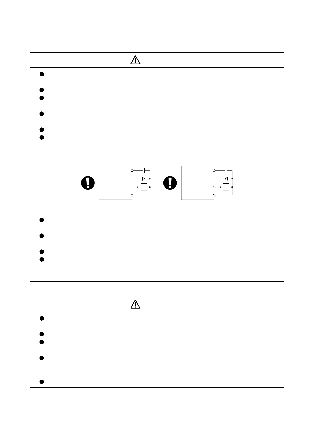
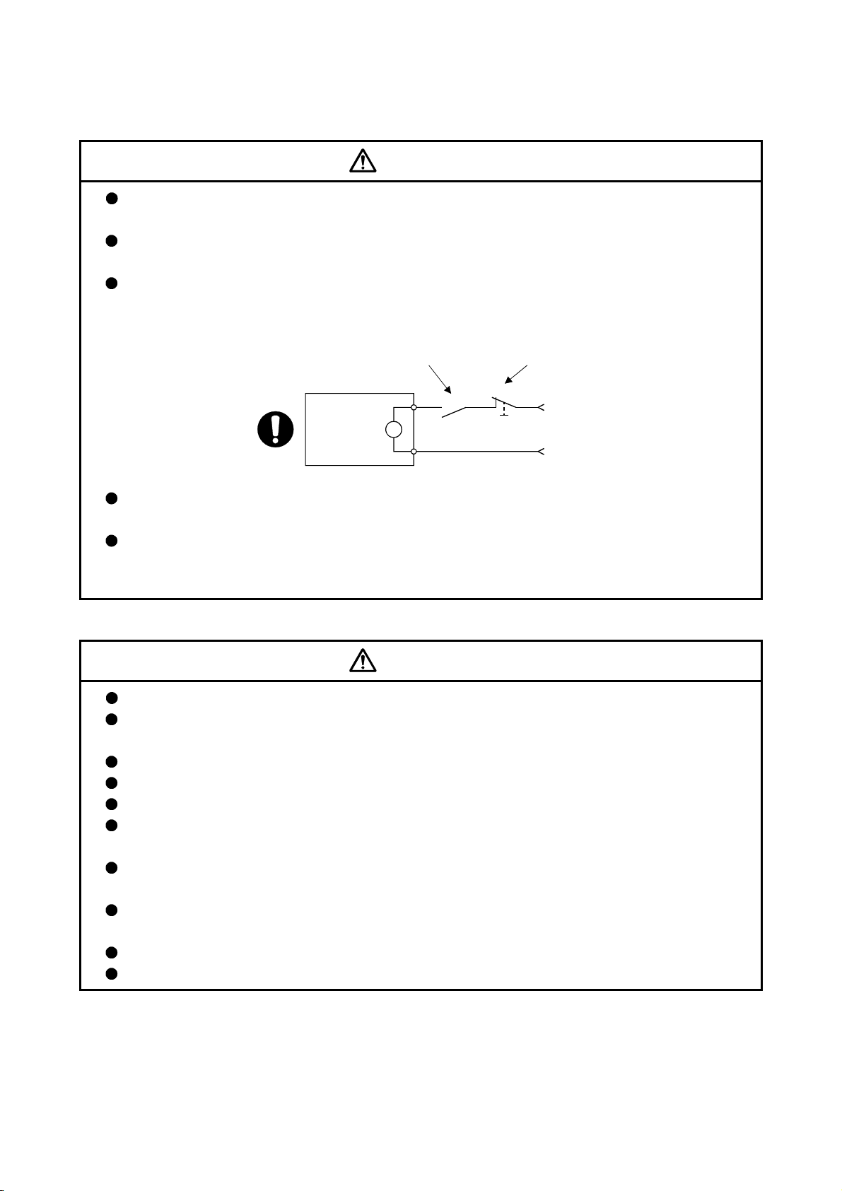
Do not mistake the direction of the surge absorbing diode installed on the DC relay for the
control signal output of brake signals, etc. Incorrect installation may lead to signals not being
output when trouble occurs or the protective functions not functioning.
Servo amplifier
DOCOM
24VDC
Servo amplifier
DOCOM
24VDC
Control output
signal
DICOM
For the sink output interface For the source output interface
RA
Control output
signal
DICOM
RA
Do not connect or disconnect the connection cables between each unit, the encoder cable or
PLC expansion cable while the power is ON.
Securely tighten the cable connector fixing screws and fixing mechanisms. Insufficient fixing may
lead to the cables combing off during operation.
Do not bundle the power line or cables.
Use applicable solderless terminals and tighten them with the specified torque.
If any solderless spade terminal is used, it may be disconnected when the terminal screw comes
loose, resulting in failure.
(5) Trial operation and adjustment
CAUTION
Confirm and adjust the program and each parameter before operation. Unpredictable
movements may occur depending on the machine.
Extreme adjustments and changes may lead to unstable operation, so never make them.
When using the absolute position system function, on starting up, and when the module or
absolute value motor has been replaced, always perform a home position return.
Before starting test operation, set the parameter speed limit value to the slowest value, and make
sure that operation can be stopped immediately by the forced stop, etc. if a hazardous state
occurs.
Before starting the operation, confirm the brake function.
A - 7
Page 9
(6) Usage methods
CAUTION
Immediately turn OFF the power if smoke, abnormal sounds or odors are emitted from the
module, servo amplifier or servomotor.
Always execute a test operation before starting actual operations after the program or parameters
have been changed or after maintenance and inspection.
Do not attempt to disassemble and repair the units excluding a qualified technician whom our
company recognized.
Do not make any modifications to the unit.
Keep the effect or electromagnetic obstacles to a minimum by installing a noise filter or by using
wire shields, etc.
Electromagnetic obstacles may affect the electronic devices used near the module or servo
amplifier.
When using the CE Mark-compliant equipment design, refer to the "EMC Installation Guidelines"
(data number IB(NA)-67339) and refer to the corresponding EMC guideline information for the
servo amplifiers and other equipment.
Note that when the reference axis speed is designated for interpolation operation, the speed of
the partner axis (2nd axis, 3rd axis and 4th axis) may be larger than the set speed (larger than
the speed limit value).
Use the units with the following conditions.
Item Conditions
Input power According to each instruction manual.
Input frequency According to each instruction manual.
Tolerable momentary
power failure
According to each instruction manual.
A - 8
Page 10
(7) Corrective actions for errors
CAUTION
If an error occurs in the self diagnosis of the module or servo amplifier, confirm the check details
according to the instruction manual, and restore the operation.
If a dangerous state is predicted in case of a power failure or product failure, use a servomotor
with an electromagnetic brake or install a brake mechanism externally.
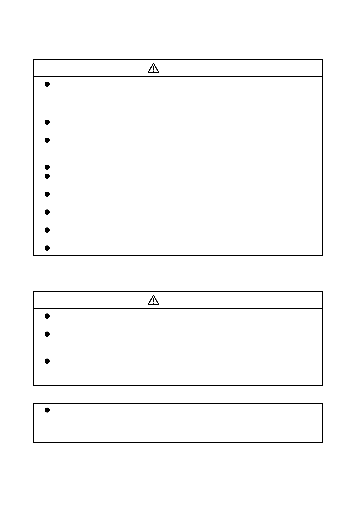
Use a double circuit construction so that the electromagnetic brake operation circuit can be
operated by emergency stop signals set externally.
Shut off with servo ON signal OFF,
alarm, electromagnetic brake signal.
Shut off with the
emergency stop
signal (EMG).
Servo motor
Electromagnetic
brake
RA1
B
EMG
24VDC
If an error occurs, remove the cause, secure the safety and then resume operation after alarm
release.
The unit may suddenly resume operation after a power failure is restored, so do not go near the
machine. (Design the machine so that personal safety can be ensured even if the machine
restarts suddenly.)
(8) Maintenance, inspection and part replacement
CAUTION
Perform the daily and periodic inspections according to the instruction manual.
Perform maintenance and inspection after backing up the program and parameters for the
module and servo amplifier.
Do not place fingers or hands in the clearance when opening or closing any opening.
Periodically replace consumable parts such as batteries according to the instruction manual.
Do not touch the lead sections such as ICs or the connector contacts.
Before touching the module, always touch grounded metal, etc. to discharge static electricity from
human body. Failure to do so may cause the module to fail or malfunction.
Do not directly touch the module's conductive parts and electronic components.
Touching them could cause an operation failure or give damage to the module.
Do not place the module or servo amplifier on metal that may cause a power leakage or wood,
plastic or vinyl that may cause static electricity buildup.
Do not perform a megger test (insulation resistance measurement) during inspection.
When replacing the module or servo amplifier, always set the new module settings correctly.
A - 9
Page 11
CAUTION
When the module or absolute value motor has been replaced, carry out a home position return
operation using one of the following methods, otherwise position displacement could occur.
1) After writing the servo data to the Simple Motion module using programming software, switch
on the power again, then perform a home position return operation.
After maintenance and inspections are completed, confirm that the position detection of the
absolute position detector function is correct.
Do not drop or impact the battery installed to the module.
Doing so may damage the battery, causing battery liquid to leak in the battery. Do not use the
dropped or impacted battery, but dispose of it.
Do not short circuit, charge, overheat, incinerate or disassemble the batteries.
The electrolytic capacitor will generate gas during a fault, so do not place your face near the
module or servo amplifier.
The electrolytic capacitor and fan will deteriorate. Periodically replace these to prevent secondary
damage from faults. Please contact with our sales representative.
Lock the control panel and prevent access to those who are not certified to handle or install
electric equipment.
Do not mount/remove the module and base or terminal block more than 50 times (IEC61131-2-
compliant), after the first use of the product. Failure to do so may cause malfunction.
Do not burn or break a module and servo amplifier. Doing so may cause a toxic gas.
(9) About processing of waste
When you discard module, servo amplifier, a battery (primary battery) and other option articles,
please follow the law of each country (area).
CAUTION
This product is not designed or manufactured to be used in equipment or systems in situations
that can affect or endanger human life.
When considering this product for operation in special applications such as machinery or
systems used in passenger transportation, medical, aerospace, atomic power, electric power, or
submarine repeating applications, please contact your nearest Mitsubishi sales representative.
Although this product was manufactured under conditions of strict quality control, you are
strongly advised to install safety devices to forestall serious accidents when it is used in facilities
where a breakdown in the product is likely to cause a serious accident.
(10) General cautions
All drawings provided in the instruction manual show the state with the covers and safety
partitions removed to explain detailed sections. When operating the product, always return the
covers and partitions to the designated positions, and operate according to the instruction
manual.
A - 10
Page 12

CONDITIONS OF USE FOR THE PRODUCT
(1) Mitsubishi programmable controller ("the PRODUCT") shall be used in conditions;
i) where any problem, fault or failure occurring in the PRODUCT, if any, shall not lead to any major or
serious accident; and
ii) where the backup and fail-safe function are systematically or automatically provided outside of the
PRODUCT for the case of any problem, fault or failure occurring in the PRODUCT.
(2) The PRODUCT has been designed and manufactured for the purpose of being used in general industries.
MITSUBISHI SHALL HAVE NO RESPONSIBILITY OR LIABILITY (INCLUDING, BUT NOT LIMITED TO
ANY AND ALL RESPONSIBILITY OR LIABILITY BASED ON CONTRACT, WARRANTY, TORT,
PRODUCT LIABILITY) FOR ANY INJURY OR DEATH TO PERSONS OR LOSS OR DAMAGE TO
PROPERTY CAUSED BY the PRODUCT THAT ARE OPERATED OR USED IN APPLICATION NOT
INTENDED OR EXCLUDED BY INSTRUCTIONS, PRECAUTIONS, OR WARNING CONTAINED IN
MITSUBISHI'S USER, INSTRUCTION AND/OR SAFETY MANUALS, TECHNICAL BULLETINS AND
GUIDELINES FOR the PRODUCT.
("Prohibited Application")
Prohibited Applications include, but not limited to, the use of the PRODUCT in;
• Nuclear Power Plants and any other power plants operated by Power companies, and/or any other cases
in which the public could be affected if any problem or fault occurs in the PRODUCT.
• Railway companies or Public service purposes, and/or any other cases in which establishment of a
special quality assurance system is required by the Purchaser or End User.
• Aircraft or Aerospace, Medical applications, Train equipment, transport equipment such as Elevator and
Escalator, Incineration and Fuel devices, Vehicles, Manned transportation, Equipment for Recreation and
Amusement, and Safety devices, handling of Nuclear or Hazardous Materials or Chemicals, Mining and
Drilling, and/or other applications where there is a significant risk of injury to the public or property.
Notwithstanding the above, restrictions Mitsubishi may in its sole discretion, authorize use of the
PRODUCT in one or more of the Prohibited Applications, provided that the usage of the PRODUCT is
limited only for the specific applications agreed to by Mitsubishi and provided further that no special quality
assurance or fail-safe, redundant or other safety features which exceed the general specifications of the
PRODUCTs are required. For details, please contact the Mitsubishi representative in your region.
A - 11
Page 13

INTRODUCTION
Thank you for purchasing the Mitsubishi MELSEC-Q series programmable controllers.
This manual describes the functions and programming of the Simple Motion module.
Before using this product, please read this manual and the relevant manuals carefully and develop familiarity
with the functions and performance of the MELSEC-Q series programmable controller to handle the product
correctly.
When applying the program examples introduced in this manual to the actual system, ensure the applicability
and confirm that it will not cause system control problems.
Please make sure that the end users read this manual.
REMARK
• Unless otherwise specified, this manual describes the program examples in which
the I/O numbers of X/Y00 to X/Y1F are assigned for a Q series Simple Motion
module. I/O number assignment is required for using the program examples
described in the manual.
For I/O number assignment, refer to the following.
QnUCPU User's Manual (Function Explanation, Program Fundamentals)
Qn(H)/QnPH/QnPRHCPU User's Manual (Function Explanation, Program
Fundamentals)
• Operating procedures are explained using GX Works2.
A - 12
Page 14

REVISIONS
The manual number is given on the bottom left of the back cover.
Print Date Manual Number Revision
Feb., 2012 IB(NA)-0300185-A First edition
Sep., 2013 IB(NA)-0300185-B
[Additional function]
Driver communication function, Inverter FR-A700 series, Synchronous
encoder via servo amplifier, Operation cycle setting for
QD77MS2/QD77MS4
[Additional correction/partial correction]
Safety precautions, Relevant manuals, Restrictions by the SERIAL
No. and version, Parameters, Monitor data, Control data, List of
errors, List of warnings, List of buffer memory address, Serial absolute
synchronous encoder cable
Nov., 2014 IB(NA)-0300185-C
[Additional function]
Servo driver VCII series manufactured by Nikki Denso Co., Ltd.
(SSCNET
/H compatible), MR-JE-B
[Additional correction/partial correction]
Restrictions by the SERIAL No. and version, Parameters, Monitor
data, List of errors, List of warnings
Japanese Manual Version IB-0300184
This manual confers no industrial property rights or any rights of any other kind, nor does it confer any patent licenses.
Mitsubishi Electric Corporation cannot be held responsible for any problems involving industrial property rights which
may occur as a result of using the contents noted in this manual.
2012 MITSUBISHI ELECTRIC CORPORATION
A - 13
Page 15

CONTENTS
SAFETY PRECAUTIONS ............................................................................................................................. A- 1
CONDITIONS OF USE FOR THE PRODUCT ............................................................................................. A-11
INTRODUCTION ............................................................................................................................................ A-12
REVISIONS .................................................................................................................................................... A-13
CONTENTS .................................................................................................................................................... A-14
COMPLIANCE WITH THE EMC AND LOW VOLTAGE DIRECTIVES ....................................................... A-22
RELEVANT MANUALS ................................................................................................................................. A-22
MANUAL PAGE ORGANIZATION ................................................................................................................ A-24
TERMS ........................................................................................................................................................... A-25
PACKING LIST ............................................................................................................................................... A-26
Section 1 Product Specifications and Handling
1. Product Outline 1- 1 to 1-30
1.1 Positioning control .................................................................................................................................... 1- 2
1.1.1 Features of QD77MS ........................................................................................................................ 1- 2
1.1.2 Purpose and applications of positioning control ............................................................................... 1- 6
1.1.3 Mechanism of positioning control ..................................................................................................... 1- 8
1.1.4 Overview of positioning control f unctions ......................................................................................... 1- 9
1.1.5 Outline design of positioning system ................................................................................................ 1-19
1.1.6 Communicating signals between QD77MS and each module ........................................................ 1-20
1.2 Flow of system operation ......................................................................................................................... 1-24
1.2.1 Flow of all processes ......................................................................................................................... 1-24
1.2.2 Outline of starting .............................................................................................................................. 1-26
1.2.3 Outline of stopping ............................................................................................................................ 1-28
1.2.4 Outline for restarting .......................................................................................................................... 1-30
2. System Configuration 2- 1 to 2-12
2.1 General image of system ......................................................................................................................... 2- 2
2.2 Component list ......................................................................................................................................... 2- 4
2.3 Applicable system .................................................................................................................................... 2- 8
2.4 How to check the function version and SERIAL No. .............................................................................. 2-10
2.5 Restrictions by the SERIAL No. and version .......................................................................................... 2-11
3. Specifications and Functions 3- 1 to 3-48
3.1 Performance specifications ...................................................................................................................... 3- 2
3.2 List of functions ........................................................................................................................................ 3- 4
3.2.1 QD77MS control functions ................................................................................................................ 3- 4
3.2.2 QD77MS main functions ................................................................................................................... 3- 7
3.2.3 QD77MS sub functions ..................................................................................................................... 3- 9
3.2.4 QD77MS common functions ............................................................................................................. 3-11
3.2.5 Combination of QD77MS main functions and sub functions ........................................................... 3-14
3.3 Specifications of input/output signals with PLC CPU ............................................................................. 3-16
3.3.1 List of input/output signals with PLC CPU ........................................................................................ 3-16
A - 14
Page 16

3.3.2 Details of input signals (QD77MS
3.3.3 Details of output signals (PLC CPU
3.4 Specifications of interfaces with external devices ................................................................................... 3-23
3.4.1 Electrical specifications of input signals ........................................................................................... 3-23
3.4.2 Signal layout for external input connection connector ..................................................................... 3-25
3.4.3 List of input signal details .................................................................................................................. 3-27
3.4.4 Interface internal circuit ..................................................................................................................... 3-30
3.5 External circuit design .............................................................................................................................. 3-34
4. Installation, Wiring and Maintenance of the Product 4- 1 to 4-20
4.1 Outline of installation, wiring and maintenance ....................................................................................... 4- 2
4.1.1 Installation, wiring and maintenance procedures ............................................................................. 4- 2
4.1.2 Names of each part ........................................................................................................................... 4- 3
4.1.3 Handling precautions ........................................................................................................................ 4- 5
4.2 Installation ................................................................................................................................................ 4- 7
4.2.1 Precautions for installation ................................................................................................................ 4- 7
4.3 Wiring ........................................................................................................................................................ 4- 8
4.3.1 Precautions for wiring ........................................................................................................................ 4- 8
4.4 Confirming the installation and wiring ...................................................................................................... 4-19
4.4.1 Items to confirm when installation and wiring are completed .......................................................... 4-19
4.5 Maintenance ............................................................................................................................................. 4-20
4.5.1 Precautions for maintenance ............................................................................................................ 4-20
4.5.2 Disposal instructions ......................................................................................................................... 4-20
PLC CPU) ............................................................................ 3-19
QD77MS) .......................................................................... 3-21
5. Data Used for Positioning Control 5- 1 to 5-202
5.1 Types of data ............................................................................................................................................ 5- 2
5.1.1 Parameters and data required for control......................................................................................... 5- 2
5.1.2 Setting items for positioning parameters .......................................................................................... 5- 5
5.1.3 Setting items for OPR parameters .................................................................................................... 5- 7
5.1.4 Setting items for expansion parameters ........................................................................................... 5- 8
5.1.5 Setting items for servo parameters ................................................................................................... 5- 8
5.1.6 Setting items for positioning data ...................................................................................................... 5- 9
5.1.7 Setting items for block start data ...................................................................................................... 5-11
5.1.8 Setting items for condition data ........................................................................................................ 5-12
5.1.9 Types and roles of monitor data ....................................................................................................... 5-13
5.1.10 Types and roles of control data ...................................................................................................... 5-18
5.2 List of parameters .................................................................................................................................... 5-22
5.2.1 Basic parameters 1 ........................................................................................................................... 5-22
5.2.2 Basic parameters 2 ........................................................................................................................... 5-28
5.2.3 Detailed parameters 1 ....................................................................................................................... 5-29
5.2.4 Detailed parameters 2 ....................................................................................................................... 5-40
5.2.5 OPR basic parameters ...................................................................................................................... 5-52
5.2.6 OPR detailed parameters ................................................................................................................. 5-60
5.2.7 Expansion parameters ...................................................................................................................... 5-65
5.2.8 Servo parameters .............................................................................................................................. 5-70
5.3 List of positioning data ............................................................................................................................. 5-83
5.4 List of block start data .............................................................................................................................. 5-99
5.5 List of condition data .............................................................................................................................. 5-105
5.6 List of monitor data ................................................................................................................................. 5-116
A - 15
Page 17

5.6.1 System monitor data ....................................................................................................................... 5-116
5.6.2 Axis monitor data ............................................................................................................................. 5-130
5.7 List of control data .................................................................................................................................. 5-158
5.7.1 System control data ........................................................................................................................ 5-158
5.7.2 Axis control data .............................................................................................................................. 5-166
5.7.3 Expansion axis control data ............................................................................................................ 5-200
6. Sequence Program Used for Positioning Control 6- 1 to 6-76
6.1 Precautions for creating program ............................................................................................................ 6- 2
6.2 List of devices used .................................................................................................................................. 6- 6
6.3 Creating a program .................................................................................................................................. 6-16
6.3.1 General configuration of program ..................................................................................................... 6-16
6.3.2 Positioning control operation program .............................................................................................. 6-17
6.4 Positioning program examples ................................................................................................................ 6-21
6.5 Program details ........................................................................................................................................ 6-53
6.5.1 Initialization program ......................................................................................................................... 6-53
6.5.2 Start details setting program ............................................................................................................. 6-54
6.5.3 Start program ..................................................................................................................................... 6-56
6.5.4 Continuous operation interrupt program ........................................................................................... 6-68
6.5.5 Restart program ................................................................................................................................ 6-70
6.5.6 Stop program ..................................................................................................................................... 6-73
7. Memory Configuration and Data Process 7- 1 to 7-20
7.1 Configuration and roles of QD77MS memory ......................................................................................... 7- 2
7.1.1 Configuration and roles of QD77MS memory .................................................................................. 7- 2
7.1.2 Buffer memory area configuration .................................................................................................... 7- 5
7.2 Data transmission process ...................................................................................................................... 7- 7
A - 16
Page 18

Section 2 Control Details and Setting
8. OPR Control 8- 1 to 8-20
8.1 Outline of OPR control ............................................................................................................................. 8- 2
8.1.1 Two types of OPR control ................................................................................................................. 8- 2
8.2 Machine OPR ........................................................................................................................................... 8- 5
8.2.1 Outline of the machine OPR operation ............................................................................................. 8- 5
8.2.2 Machine OPR method ....................................................................................................................... 8- 6
8.2.3 OPR method (1): Near-point dog method ........................................................................................ 8- 7
8.2.4 OPR method (2): Count method 1) .................................................................................................. 8- 9
8.2.5 OPR method (3): Count method 2) .................................................................................................. 8-11
8.2.6 OPR method (4): Data set method ................................................................................................... 8-13
8.2.7 OPR method (5): Scale origin signal detection method ................................................................... 8-14
8.3 Fast OPR .................................................................................................................................................. 8-17
8.3.1 Outline of the fast OPR operation ..................................................................................................... 8-17
8.4 Selection of the OPR setting condition .................................................................................................. 8-19
8.4.1 Outline of the OPR setting condition ................................................................................................ 8-19
9. Major Positioning Control 9- 1 to 9-134
9.1 Outline of major positioning controls ....................................................................................................... 9- 2
9.1.1 Data required for major positioning control ...................................................................................... 9- 4
9.1.2 Operation patterns of major positioning controls ............................................................................. 9- 5
9.1.3 Designating the positioning address................................................................................................. 9-15
9.1.4 Confirming the current value ............................................................................................................. 9-16
9.1.5 Control unit "degree" handling .......................................................................................................... 9-18
9.1.6 Interpolation control ........................................................................................................................... 9-21
9.2 Setting the positioning data .................................................................................................................... 9-26
9.2.1 Relation between each control and positioning data ....................................................................... 9-26
9.2.2 1-axis linear control ........................................................................................................................... 9-28
9.2.3 2-axis linear interpolation control ...................................................................................................... 9-32
9.2.4 3-axis linear interpolation control ...................................................................................................... 9-38
9.2.5 4-axis linear interpolation control ...................................................................................................... 9-44
9.2.6 1-axis fixed-feed control .................................................................................................................... 9-49
9.2.7 2-axis fixed-feed control (interpolation) ............................................................................................ 9-52
9.2.8 3-axis fixed-feed control (interpolation) ............................................................................................ 9-54
9.2.9 4-axis fixed-feed control (interpolation) ........................................................................................... 9-59
9.2.10 2-axis circular interpolation control with sub point designation ..................................................... 9-62
9.2.11 2-axis circular interpolation control with center point designation ................................................. 9-68
9.2.12 1-axis speed control ........................................................................................................................ 9-76
9.2.13 2-axis speed control ........................................................................................................................ 9-79
9.2.14 3-axis speed control ........................................................................................................................ 9-83
9.2.15 4-axis speed control ........................................................................................................................ 9-87
9.2.16 Speed-position switching control (INC mode) ................................................................................ 9-92
9.2.17 Speed-position switching control (ABS mode) ............................................................................. 9-103
9.2.18 Position-speed switching control .................................................................................................. 9-112
9.2.19 Current value changing ................................................................................................................. 9-122
9.2.20 NOP instruction ............................................................................................................................. 9-127
9.2.21 JUMP instruction ........................................................................................................................... 9-128
A - 17
Page 19

9.2.22 LOOP ............................................................................................................................................. 9-130
9.2.23 LEND ............................................................................................................................................. 9-132
10. High-Level Positioning Control 10- 1 to 10-30
10.1 Outline of high-level positioning control .............................................................................................. 10- 2
10.1.1 Data required for high-level positioning control ............................................................................ 10- 3
10.1.2 "Block start data" and "condition data" configuration ................................................................... 10- 4
10.2 High-level positioning control execution procedure ............................................................................ 10- 6
10.3 Setting the block start data .................................................................................................................. 10- 7
10.3.1 Relation between various controls and block start data .............................................................. 10- 7
10.3.2 Block start (normal start) ............................................................................................................. 10- 8
10.3.3 Condition start ............................................................................................................................... 10-10
10.3.4 Wait start........................................................................................................................................ 10-11
10.3.5 Simultaneous start ....................................................................................................................... 10-12
10.3.6 Repeated start (FOR loop) .......................................................................................................... 10-13
10.3.7 Repeated start (FOR condition) .................................................................................................. 10-14
10.3.8 Restrictions when using the NEXT start ....................................................................................... 10-15
10.4 Setting the condition data .................................................................................................................... 10-16
10.4.1 Relation between various controls and the condition data .......................................................... 10-16
10.4.2 Condition data setting examples .................................................................................................. 10-19
10.5 Multiple axes simultaneous start control ............................................................................................. 10-21
10.6 Start program for high-level positioning control .................................................................................. 10-26
10.6.1 Starting high-level positioning control ........................................................................................... 10-26
10.6.2 Example of a start program for high-level positioning control ..................................................... 10-27
11. Manual Control 11- 1 to 11-32
11.1 Outline of manual control ................................................................................................................... 11- 2
11.1.1 Three manual control methods ..................................................................................................... 11- 2
11.2 JOG operation ...................................................................................................................................... 11- 4
11.2.1 Outline of JOG operation .............................................................................................................. 11- 4
11.2.2 JOG operation execution procedure ............................................................................................ 11- 7
11.2.3 Setting the required parameters for JOG operation ..................................................................... 11- 8
11.2.4 Creating start programs for JOG operation .................................................................................. 11-10
11.2.5 JOG operation example ................................................................................................................ 11-12
11.3 Inching operation .................................................................................................................................. 11-15
11.3.1 Outline of inching operation .......................................................................................................... 11-15
11.3.2 Inching operation execution procedure ........................................................................................ 11-18
11.3.3 Setting the required parameters for inching operation ................................................................ 11-19
11.3.4 Creating a program to enable/disable the inching operation ....................................................... 11-20
11.3.5 Inching operation example ............................................................................................................ 11-22
11.4 Manual pulse generator operation ....................................................................................................... 11-24
11.4.1 Outline of manual pulse generator operation ............................................................................... 11-24
11.4.2 Manual pulse generator operation execution procedure ............................................................. 11-28
11.4.3 Setting the required parameters for manual pulse generator operation ..................................... 11-29
11.4.4 Creating a program to enable/disable the manual pulse generator operation ............................ 11-30
12. Expansion Control 12- 1 to 12-34
12.1 Speed-torque control ........................................................................................................................... 12- 2
12.1.1 Outline of speed-torque control .................................................................................................... 12- 2
A - 18
Page 20

12.1.2 Setting the required parameters for speed-torque control ........................................................... 12- 4
12.1.3 Setting the required data for speed-torque control ...................................................................... 12- 5
12.1.4 Operation of speed-torque control ................................................................................................ 12- 7
12.2 Synchronous control ............................................................................................................................ 12-34
13. Control Sub Functions 13- 1 to 13-108
13.1 Outline of sub functions ....................................................................................................................... 13- 2
13.1.1 Outline of sub functions ................................................................................................................ 13- 2
13.2 Sub functions specifically for machine OPR ....................................................................................... 13- 4
13.2.1 OPR retry function ......................................................................................................................... 13- 4
13.2.2 OP shift function .......................................................................................................................... 13- 8
13.3 Functions for compensating the control .............................................................................................. 13-11
13.3.1 Backlash compensation function .................................................................................................. 13-11
13.3.2 Electronic gear function ................................................................................................................ 13-13
13.3.3 Near pass function ........................................................................................................................ 13-20
13.4 Functions to limit the control ................................................................................................................ 13-22
13.4.1 Speed limit function ....................................................................................................................... 13-22
13.4.2 Torque limit function ...................................................................................................................... 13-24
13.4.3 Software stroke limit function ........................................................................................................ 13-28
13.4.4 Hardware stroke limit function ...................................................................................................... 13-35
13.4.5 Forced stop function ...................................................................................................................... 13-39
13.5 Functions to change the control details ............................................................................................... 13-42
13.5.1 Speed change function ................................................................................................................. 13-42
13.5.2 Override function ........................................................................................................................... 13-49
13.5.3 Acceleration/deceleration time change function .......................................................................... 13-52
13.5.4 Torque change function ................................................................................................................ 13-57
13.5.5 Target position change function ................................................................................................... 13-61
13.6 Absolute position system ..................................................................................................................... 13-65
13.7 Other functions ..................................................................................................................................... 13-6 7
13.7.1 Step function.................................................................................................................................. 13-67
13.7.2 Skip functi on .................................................................................................................................. 13-72
13.7.3 M code output function .................................................................................................................. 13-75
13.7.4 Teaching function .......................................................................................................................... 13-79
13.7.5 Command in-position function ...................................................................................................... 13-85
13.7.6 Acceleration/deceleration processing function ............................................................................. 13-88
13.7.7 Pre-reading start function .............................................................................................................. 13-91
13.7.8 Deceleration start flag function .................................................................................................... 13-94
13.7.9 Stop command processing for deceleration stop function ........................................................ 13-97
13.7.10 Speed control 10 x multiplier setting for degree axis function .............................................. 13-100
13.7.11 Operation setting for incompletion of OPR function .............................................................. 13-103
13.8 Servo ON/OFF ................................................................................................................................... 13-105
13.8.1 Servo ON/OFF ............................................................................................................................ 13-105
13.8.2 Follow up function ....................................................................................................................... 13-107
14. Common Functions 14- 1 to 14-66
14.1 Outline of common functions ............................................................................................................... 14- 2
14.2 Parameter initialization function ........................................................................................................... 14- 4
14.3 Execution data backup function .......................................................................................................... 14- 6
14.4 External signal selection function ........................................................................................................ 14- 8
14.5 External I/O signal logic switching function ......................................................................................... 14-14
A - 19
Page 21

14.6 History monitor function ....................................................................................................................... 14-16
14.7 Amplifier-less operation function ......................................................................................................... 14-20
14.8 Virtual servo amplifier function ............................................................................................................ 14-27
14.9 Driver communication function ............................................................................................................ 14-31
14.10 Mark detection function ...................................................................................................................... 14-3 9
14.11 Optional data monitor function........................................................................................................... 14-52
14.12 Module error collection function......................................................................................................... 14-56
14.13 Connect/disconnect function of SSCNET communication ............................................................... 14-57
14.14 QD75MH initial value setting function ............................................................................................... 14-63
14.15 Hot line forced stop function .............................................................................................................. 14-65
15. Dedicated Instructions 15- 1 to 15-18
15.1 List of dedicated instructions ............................................................................................................... 15- 2
15.2 Interlock during dedicated instruction is executed .............................................................................. 15- 2
15.3 ZP.PSTRT1, ZP.PSTRT2, ZP.PSTRT3, ZP.PSTRT4 ........................................................................ 15- 3
15.4 ZP.TEACH1, ZP.TEACH2, ZP.TEACH3, ZP.TEACH4 ...................................................................... 15- 7
15.5 ZP.PFWRT ........................................................................................................................................... 15-11
15.6 ZP.PINIT ............................................................................................................................................... 15-15
16. Troubleshooting 16- 1 to 16-66
16.1 Checking errors using GX Works2 ...................................................................................................... 16- 2
16.2 Troubleshooting ................................................................................................................................... 16- 5
16.3 Error and warning details ..................................................................................................................... 16- 9
16.4 List of errors ......................................................................................................................................... 16-16
16.4.1 QD77MS detection error ............................................................................................................... 16-16
16.4.2 Servo amplifier detection error ...................................................................................................... 16-5 2
16.5 List of warnings .................................................................................................................................... 16-54
16.5.1 QD77MS detection warning .......................................................................................................... 16-54
16.5.2 Servo amplifier detection warning ................................................................................................ 16-66
Appendices Appendix- 1 to Appendix-88
Appendix 1 List of buffer memory addresses .................................................................................. Appendix- 2
Appendix 2 Connection with servo amplifiers .................................................................................. Appendix-28
Appendix 2.1 SSCNET
Appendix 2.2 Serial absolute synchronous encoder cable .......................................................... Appendix-33
Appendix 2.3 SSCNET
Mitsubishi Electric System & Service ..................................................................... Appendix-36
Appendix 3 Connection with external device ................................................................................... Appendix-37
Appendix 3.1 Con nector ................................................................................................................ Appendix-37
Appendix 3.2 External input signal cable ...................................................................................... Appendix-39
Appendix 3.3 Manual pulse generator (MR-HDP01) ................................................................... Appendix-44
Appendix 4 Comparisons with positioning modules /LD77MH models ........................................... Appendix-45
Appendix 4.1 Differences with QD75MH models ......................................................................... Appendix-45
Appendix 4.2 Differences with LD77MH models .......................................................................... Appendix-58
Appendix 5 When using GX Works2 ................................................................................................ Appendix-63
Appendix 6 Compatible devices with SSCNET
Appendix 6.1 Servo driver VCII series manufactured by Nikki Denso Co., Ltd. ......................... Appendix-64
Appendix 6.2 Inverter FR-A700 series ......................................................................................... Appendix-75
Appendix 6.3 Connection with MR-JE-B ...................................................................................... Appendix-85
cables ................................................................................................. Appendix-29
cable (SC-J3BUS_M-C) manufactured by
............................................................................ Appendix-64
A - 20
Page 22

Appendix 7 External dimension drawing .......................................................................................... Appendix-86
A - 21
Page 23

COMPLIANCE WITH THE EMC AND LOW VOLTAGE DIRECTIVES
(1) For programmable controller system
To configure a system meeting the requirements of the EMC and Low Voltage
Directives when incorporating the Mitsubishi programmable controller (EMC and
Low Voltage Directives compliant) into other machinery or equipment, refer to the
Safety Guidelines provided with the main base unit. Also, refer to "Example of
measure against noise for compliance with the EMC directive" of the Section
4.3.1 of this manual.
The CE mark on the side of the programmable controller indicates compliance
with EMC and Low Voltage Directives.
(2) For the product
To make this product comply with EMC and Low Voltage Directives, refer to
Section 4.3.1 "Precautions for wiring".
RELEVANT MANUALS
<Manual number (model code)>
MELSEC-Q QD77MS Simple Motion Module User's Manual
(Positioning Control)
MELSEC-Q/L QD77MS/QD77GF/LD77MS/LD77MH Simple
Motion Module User's Manual (Synchronous Control)
(1) Simple Motion module
Manual Name
<IB-0300185, 1XB947>
<IB-0300174, 1XB943>
<Manual number (model code)>
QCPU User's Manual
(Hardware Design, Maintenance and Inspection)
QnUCPU User's Manual
(Function Explanation, Program Fundamentals)
Qn(H)/QnPH/QnPRHCPU User's Manual
(Function Explanation, Program Fundamentals)
(2) CPU module
Manual Name
<SH-080483ENG, 13JR73>
<SH-080807ENG, 13JZ27>
<SH-080808ENG, 13JZ28>
Description
Specifications of the QD77MS and information on how to
establish a system, maintenance and inspection, and
troubleshooting
Functions, programming and buffer memory for the
positioning control of the QD77MS
Functions, programming and buffer memory for the
synchronous control of the Simple Motion module
Description
Specifications of the hardware (CPU modules, power supply
modules, base units, batteries, and memory cards), system
maintenance and inspection, and troubleshooting
Functions, devices, and programming of the CPU module
Functions, devices, and programming of the CPU module
A - 22
Page 24

<Manual number (model code)>
GX Works2 Version1 Operating Manual
(Common)
GX Works2 Version1 Operating Manual
(Intelligent Function Module)
(3) Programming tool
Manual Name
<SH-080779ENG, 13JU63>
<SH-080921ENG, 13JU69>
<Manual number (model code)>
SSCNET /H Interface AC Servo
MR-J4-_B(-RJ)/MR-J4-_B4(-RJ)/MR-J4-_B1(-RJ) Servo
Amplifier Instruction Manual
SSCNET /H Interface Multi-axis AC Servo
MR-J4W2-_B/MR-J4W3-_B Servo Amplifier Instruction
Manual
SSCNET Interface MR-J3-_B Servo Amplifier Instruction
Manual
SSCNET Compatible Linear Servo
MR-J3-_B-RJ004(U_) Instruction Manual
SSCNET Fully Closed Loop Control
MR-J3-_B-RJ006 Servo Amplifier Instruction Manual
SSCNET Interface 2-axis AC Servo Amplifier
MR-J3W-0303BN6/MR-J3W-_B Servo Amplifier Instruction
Manual
SSCNET Interface Direct Drive Servo
MR-J3-_B-RJ080W Instruction Manual
SSCNET Interface Drive Safety Integrated
MR-J3-_B Safety Servo Amplifier Instruction Manual
MR-JE-_B Servo Amplifier Instruction Manual
(4) Servo amplifier
Manual Name
<SH-030106, 1CW805>
<SH-030105, 1CW806>
<SH-030051, 1CW202>
<SH-030054, 1CW943>
<SH-030056, 1CW304>
<SH-030073, 1CW604>
<SH-030079, 1CW601>
<SH-030084, ---- >
<SH030152, 1CW750>
Description
System configuration, parameter settings, and online
operations (common to Simple project and Structured
project) of GX Works2
Parameter settings, monitoring, and operations of the
predefined protocol support function of intelligent function
modules, using GX Works2
Description
This manual explains the I/O signals, parts names,
parameters, start-up procedure and others for
MR-J4-_B(-RJ)/MR-J4-_B4(-RJ)/MR-J4-_B1(-RJ) servo
amplifier.
This manual explains the I/O signals, parts names,
parameters, start-up procedure and others for multi-axis
AC servo MR-J4W2-_B/MR-J4W3-_B servo amplifier.
This manual explains the I/O signals, parts names,
parameters, start-up procedure and others for MR-J3-
servo amplifier.
This manual explains the I/O signals, parts names,
parameters, start-up procedure and others for Iinear servo
MR-J3-
_B-RJ004(U_).
This manual explains the I/O signals, parts names,
parameters, start-up procedure and others for fully closed
loop control MR-J3-
This manual explains the I/O signals, parts names,
parameters, start-up procedure and others for 2-axis AC
servo amplifier MR-J3W-0303BN6/MR-J3W-
amplifier.
This manual explains the I/O signals, parts names,
parameters, start-up procedure and others for direct drive
servo MR-J3-
This manual explains the I/O signals, parts names,
parameters, start-up procedure and others for safety
integrated MR-J3-
This manual explains the I/O signals, parts names,
parameters, start-up procedure and others for MR-JE-_B
servo amplifier.
_B-RJ006 servo amplifier.
_B servo
_B-RJ080W.
_B safety servo amplifier.
_B
A - 23
Page 25
MANUAL PAGE ORGANIZATION
The symbols used in this manual are shown below.
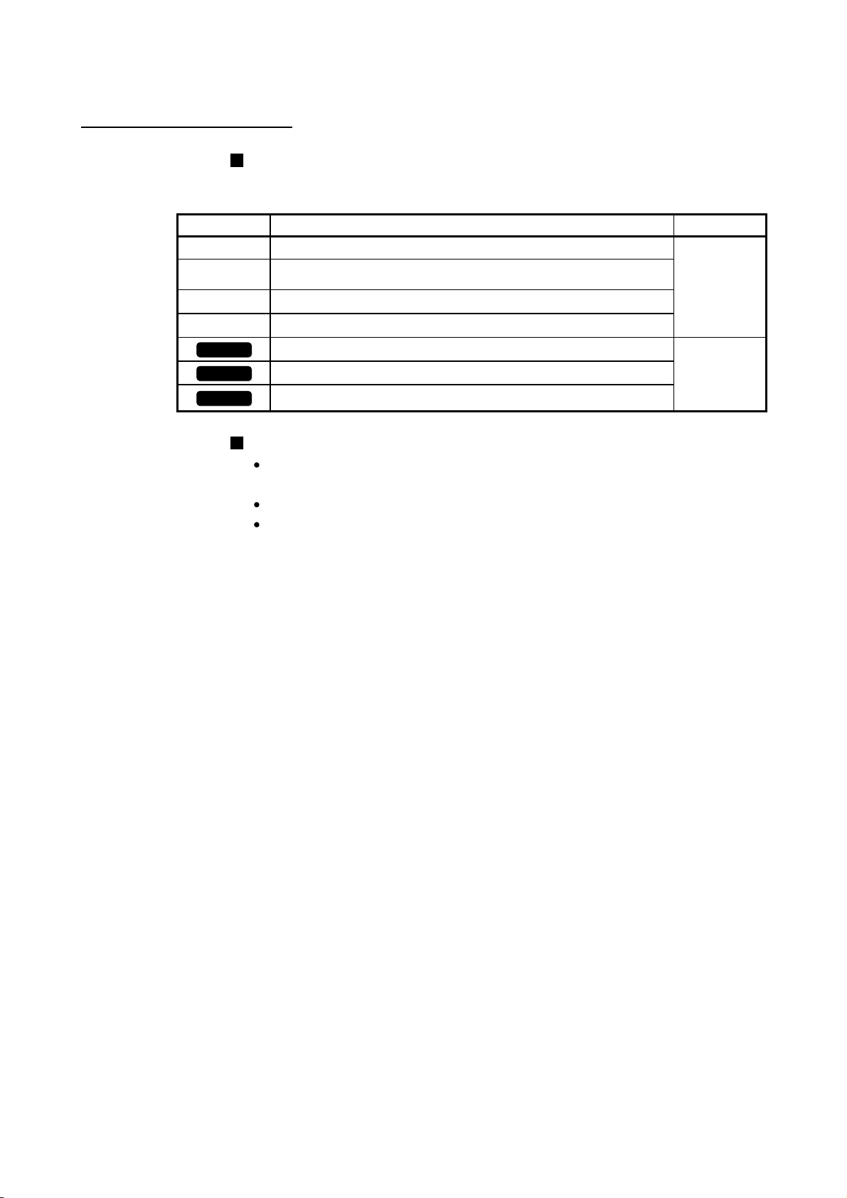
The following symbols represent the buffer memories supported for each axis.
Symbol Description Reference
[Pr. * ]
[Da. * ]
[Md. * ]
[Cd. * ]
QD77MS2
QD77MS4
QD77MS16
(A serial No. is inserted in the "*" mark.)
Symbol that indicates positioning parameter and OPR parameter item.
Symbol that indicates positioning data, block start data and condition
data item.
Symbol that indicates monitor data item.
Symbol that indicates control data item.
Symbol that indicates correspondence to only QD77MS2.
Symbol that indicates correspondence to only QD77MS4.
Symbol that indicates correspondence to only QD77MS16.
Representation of numerical values used in this manual.
Buffer memory addresses, error codes and warning codes are represented in
decimal.
X/Y devices are represented in hexadecimal.
Setting data and monitor data are represented in decimal or hexadecimal. Data
ended by "H" or "h" is represented in hexadecimal.
Chapter 5
—
(Example) 10.........Decimal
10H......Hexadecimal
A - 24
Page 26

TERMS
Unless otherwise specified, this manual uses the following terms.
Term Description
PLC CPU Abbreviation for the MELSEC-Q series PLC CPU module.
QCPU Another term for the MELSEC-Q series PLC CPU module.
Simple Motion module Abbreviation for the MELSEC-Q series Simple Motion module.
QD77MS Another term for the MELSEC-Q series QD77MS Simple Motion module.
MR-J4(W)-B MR-J4-_B/MR-J4W-_B servo amplifier series
MR-J3(W)-B MR-J3-_B/MR-J3W-_B servo amplifier series
MR-JE-B MR-JE-_B Servo amplifier series
Programming tool Generic term for GX Works2 and MR Configurator2.
GX Works2
MR Configurator2 Product name of the setup software for the servo amplifier (Version 1.09K or later).
Intelligent function module
Servo amplifier (drive unit) Abbreviation for SSCNET /H and SSCNET compatible servo amplifier (drive unit).
Manual pulse generator Abbreviation for manual pulse generator (MR-HDP01) (prepared by user).
OPR Generic term for "Home position return".
OP Generic term for "Home position".
SSCNET /H
SSCNET
Servo network Generic term for SSCNET /H, SSCNET .
(Note)
(Note)
Product name of the software package for the MELSEC programmable controllers (Version
1.77F or later).
A MELSEC-Q/L series module that has functions other than input or output, such as A/D
converter module and D/A converter module
High speed synchronous communication network between QD77MS and servo amplifier.
(Note): SSCNET: Servo System Controller NETwork
A - 25
Page 27
PACKING LIST
The following items are included in the package of this product. Before use, check that
all the items are included.
(1) QD77MS2
QD77MS2
RUN
AX1
AX2
ERR.
AX1
AX2
QD77MS2
Before Using the ProductQD77MS2
(2) QD77MS4
QD77MS4
AX3
AX4
RUN
AX1
AX2
AX3
ERR.
AX4
QD77MS4
AX1
AX2
Before Using the ProductQD77MS4
(3) QD77MS16
QD77MS16
RUN
ERR.
AX3
AX4
AX
QD77MS16
AX1
AX2
Before Using the ProductQD77MS16
A - 26
Page 28

Section 1
Section 1 Product Specifications and Handling
Section 1 is configured for the following purposes (1) to (5).
(1) To understand the outline of positioning control, and the Simple Motion module
specifications and functions
(2) To carry out actual work such as installation and wiring
(3) To set parameters and data required for positioning control
(4) To create a sequence program required for positioning control
(5) To understand the memory configuration and data transmission process
When diverting any of the program examples introduced in this manual to the actual
system, fully verify that there are no problems in the controllability of the target system.
Read "Section 2" for details on each control.
Chapter 1 Product Outline ............................................................................................. 1- 1 to 1- 30
Chapter 2 System Configuration.................................................................................... 2- 1 to 2- 12
Chapter 3 Specifications and Functions ........................................................................ 3- 1 to 3- 48
Chapter 4 Installation, Wiring and Maintenance of the Product ................................... 4- 1 to 4- 20
Chapter 5 Data Used for Positioning Control ................................................................ 5- 1 to 5-202
Chapter 6 Sequence Program Used for Positioning Control ........................................ 6- 1 to 6- 76
Chapter 7 Memory Configuration and Data Process .................................................... 7- 1 to 7- 20
Page 29

MEMO
Page 30

Chapter 1 Product Outline
Chapter 1 Product Outline
1
The purpose and outline of positioning control using the Simple Motion module are
explained in this chapter.
Reading this chapter will help you understand what can be done using the positioning
system and which procedure to use for a specific purpose.
By understanding "What can be done", and "Which procedure to use" beforehand, the
positioning system can be structured smoothly.
1.1 Positioning control ........................................................................................................ 1- 2
1.1.1 Features of QD77MS ...................................................................................... 1- 2
1.1.2 Purpose and applications of positioning control ............................................ 1- 6
1.1.3 Mechanism of positioning control ................................................................... 1- 8
1.1.4 Overview of positioning control functions....................................................... 1- 9
1.1.5 Outline design of positioning system ............................................................. 1-19
1.1.6 Communicating signals between QD77MS and each module ..................... 1-20
1.2 Flow of system operation ............................................................................................. 1-24
1.2.1 Flow of all processes ...................................................................................... 1-24
1.2.2 Outline of starting ............................................................................................ 1-26
1.2.3 Outline of stopping .......................................................................................... 1-28
1.2.4 Outline for restarting ....................................................................................... 1-30
1 - 1
Page 31

1.1 Positioning control
1.1.1 Features of QD77MS
The QD77MS has the following features.
(1) High-speed starting time
High-speed starting time "0.88ms" (QD77MS4 use) during positioning control is
achieved.
(2) Wide variety of positioning control functions
The main functions (such as OPR control, positioning control and manual
control) which are required for any positioning system and the sub functions
which limit and add functions to those controls are supported.
(a) Enhanced OPR control
(b) Wide variety of control methods
(c) Large amount of data
Chapter 1 Product Outline
1) Additional features of OPR control
Five machine OPR methods are provided: one near-point dog method,
two count methods, one data set method and one scale origin signal
detection method. Select an applicable method according to the
system.
2) OPR retry function
The OPR retry function is provided so that the machine OPR control
can be performed from any position, regardless of the machine stop
position when the system is powered on.
Positioning controls, such as position control, speed control, speed-position
switching control, position-speed switching control, and other controls, are
provided.
1) Independent control of each axis
Controls, such as position control and speed control, can be performed
independently for each axis at any given timing.
2) Interpolation control
Interpolation controls using multiple axes can be performed.
(2- to 4-axis linear interpolation control, 2-axis circular interpolation
control, 2- to 4-axis speed control, etc.)
3) Speed-torque control
Speed control and torque control not including the position loop can be
performed.
Up to 600 positioning data (combinations of data, such as control system,
positioning address, and command speed) per axis can be set.
1 - 2
Page 32

(d) Continuous processing of multiple positioning data
Multiple positioning data can be processed continuously within one
positioning operation.
Continuous positioning control can be executed over multiple blocks, where
each block consists of multiple positioning data.
This reduces the number of executions of positioning, management of
execution status, and others.
(e) Acceleration/deceleration processing
Two acceleration/deceleration processing methods are provided:
trapezoidal acceleration/deceleration and S-curve acceleration/deceleration.
The acceleration/deceleration curve can be selected according to the
machine characteristic.
Chapter 1 Product Outline
(3) Synchronous control
The synchronous control and electronic cam control can be performed.
(4) Mark detection function
The mark detection to latch any data by the external command signal [DI1 to DI4]
can be performed.
(5) High maintainability
Maintainability is enhanced in the QD77MS.
(a) Data retention without battery
Data such as the positioning data and parameters can be stored in the flash
ROM inside the QD77MS. This feature allows the module retain the data
without a battery.
(b) Module error collection function
The QD77MS notifies error details to the PLC CPU when an error occurs.
Storing the error information in the PLC CPU allows the user to check the
error from the programming tool even after the module is powered off or
reset.
(6) Support of intelligent function module dedicated instructions
Dedicated instructions such as the positioning start instruction (Axis 1 to Axis 4)
and teaching instruction (Axis 1 to Axis 4) are provided.
The use of such dedicated instructions simplifies programs.
The dedicated instructions are fully compatible with the LD77MH/QD75MH.
1 - 3
Page 33

Chapter 1 Product Outline
(7) Setting, monitoring, and testing through GX Works2
Parameters and positioning data for the QD77MS can be set using GX Works2
(Simple Motion Module Setting).
Moreover, using the test function of GX Works2 (Simple Motion Module Setting),
users can check the wiring status and the validity of the preset parameters and
positioning data by performing test operation before creating a program for
positioning control.
The control monitor function of GX Works2 allows user to debug programs
efficiently.
The servo parameters can be set easily by using the GX Works2 in combination
with the MR Configurator2.
(8) Compatibility with the LD77MH/QD75MH
The proven programs in LD77MH/QD75MH can be used because the QD77MS
is compatible with the LD77MH/QD75MH.
(9) Forced stop function
The batch forced stop is available for all axes of servo amplifier by the forced
stop input signal of the external input.
"Valid/Invalid" of the forced stop input signal can be selected by the parameters.
(10) Connection between the QD77MS and servo amplifier with high
speed synchronous network by SSCNET (/H)
The QD77MS can be directly connected to the Mitsubishi servo amplifiers of
MR-J4-B/MR-J3-B series using the SSCNET
connected to the Mitsubishi servo amplifiers of MR-JE-B series using the
SSCNET
(a) Because the high speed synchronous network by SSCNET
(b) By the use of SSCNET
(c) The servo parameters can be set on the QD77MS side to write or read
(d) The actual current value and error description contained in the servo can
(e) The communication between the MR Configurator2 and servo amplifiers is
/H.
to connect the QD77MS and the servo amplifier, or servo amplifiers,
saving wiring can be realized. The maximum distance between the
QD77MS and servo amplifier, servo amplifier and servo amplifier of the
SSCNET
flexibility will improve at the system design.
electromagnetic noise and others from servo amplifier, etc. are reduced.
them to/from the servo amplifier using the SSCNET communication.
be checked by the buffer memory of the QD77MS.
possible via the PLC CPU.
cable on the same bus was set to 50(164.04)[m(ft.)], and the
cable (Optical communication), influence of
. Also, it can be directly
(/H)
(/H)
is used
1 - 4
Page 34

Chapter 1 Product Outline
(11) Easy application to the absolute position system
(a) The MR-J4-B/MR-JE-B/MR-J3-B series servo amplifiers and servo motors
correspond to the absolute position system. It can be realized only at
connecting the battery for absolute position system to the servo amplifier.
(b) Once the OP have been established, the OPR operation is unnecessary at
the system's power supply ON.
(c) With the absolute position system, the data set method OPR is used to
establish the OP. The wiring of near-point dog, etc. is unnecessary.
(d) When the setting unit is "degree", the absolute position system with
unlimited length fed can be configured.
1 - 5
Page 35

1.1.2 Purpose and applications of positioning control
"Positioning" refers to moving a moving body, such as a workpiece or tool (hereinafter,
generically called "workpiece") at a designated speed, and accurately stopping it at the
target position. The main application examples are shown below.
Punch press (X, Y feed positioning)
Palletizer
Y axis
servomotor
Servo
amplifier
Y axis
Conveyor control
Servomotor
(with a brake)
Gear and ball screw
Press head
Servo
amplifier
Servo
amplifier
G
Reduction
gear
Ball screw
Y axis
X axis
servomotor
Conveyor
X axis
Y axis
X axis
Gear and rack & pinion
Press
punching
QD77MS
X axis
Position detector
Palletizer
Unloader control
Chapter 1 Product Outline
To punch insulation material or leather, etc.,
as the same shape at a high yield, positioning
is carried out with the X axis and Y axis
servos.
After positioning the table with the X axis
servo, the press head is positioned with the Y
axis servo, and is then punched with the
press.
When the material type or shape changes, the
press head die is changed, and the positioning
pattern is changed.
Using the servo for one axis, the palletizer is
positioned at a high accuracy.
The amount to lower the palletizer according to
the material thickness is saved.
QD77MS
Compact machining center (ATC magazine positioning)
Servo
amplifier
QD77MS
Servomotor
Coupling
Positioning
pin
Reduction
gear
ATC tool
magazine
Tool
(12 pcs., 20 pcs.)
Rotation direction
for call ing
11
<Number of tools: 12> <Number of tools: 20>
3
9 5
410
6
8
7
Rotation direction
for calling 5, 6, 7, 8, 9 or 10
Current
value
retrieval
position
11, 12, 1, 2 or 3
1
2
12
1
220
3
19
18
17
16
15
14
4
8
9
13
10
12
11
Rotation direction
for calling
17 to 20, 1 to 5
Current
5
value
6
retrieval
7
position
Rotation direction
for calling 7 to 16
1 - 6
The ATC tool magazine for a compact
machining center is positioned.
The relation of the magazine's current value
and target value is calculated, and positioning
is carried out with forward run or reverse run to
achieve the shortest access time.
Page 36

r
Lifter
B conveyor
Counterweight
Reduction
gear
Lifter
G1
Servomotor
(with a brake)
A conveyor
Loader
C conveyor
G2
Servomotor
Servo
amplifier
Loader/unloader
Aging rack
Unloader
Servo
amplifier
Chapter 1 Product Outline
During the aging process, storage onto the
rack is carried out by positioning with the AC
servo.
The up/down positioning of the lifter is carried
out with the 1-axis servo, and the horizontal
position of the aging rack is positioned with the
2-axis servo.
QD77MS
Index table (High-accuracy indexing of angle)
Digital switch
Index table
Worm gears
QD77MS
Detector
Servomotor
Inner surface grinder
Inverter
220VAC
60Hz
QD77MS
Servomotor
G
Servo
amplifier
Motor
IM
Fix the grinding
stone, feed the
workpiece, and grind.
Operation panel
Workpiece
a
b
c
Grinding s tone
d
e
G
Motor
G
a. Total feed
amount (m)
b. Finishing
feed amount (m)
c. Compensation
amount (m)
IM
Inverter
Servo
amplifie
d. Rough grind ing speed (m/s)
e. Fine grinding
speed (m/s)
The index table is positioned at a high accuracy
using the 1-axis servo.
The grinding of the workpiece's inner surface
is controlled with the servo and inverter.
The rotation of the workpiece is controlled with
the 1-axis inverter, and the rotation of the
grinding stone is controlled with the 2-axis
inverter. The workpiece is fed and ground with
the 3-axis servo.
1 - 7
Page 37

1.1.3 Mechanism of positioning control
In the positioning system using the Simple Motion module, various software and
devices are used for the following roles.
The Simple Motion module realizes complicated positioning control when it reads in
various signals, parameters and data and is controlled with the PLC CPU.
Creates control order and
conditions as a sequence
program.
Chapter 1 Product Outline
Stores the created program.
The PLC CPU outputs the start signal and
stop signal following the stored program
to the QD77MS.
QD77MS errors, etc., are detected.
GX Works2
Sets the parameters and
positioning data for control.
Outputs the start command for
JOG operation, etc., during test
operation with the test function.
Monitors the positioning
operation.
PLC CPU
QD77MS
Simple Motion
module
Servo
amplifier
Servo motor
Outputs signals such as the start
signal, external command signal and
switching signal to the QD77MS.
Issues commands by
External signal
Manual pulse generator/
Incremental synchronous encoder
Stores the parameter and data.
Outputs data to the servo amplifier according to the
instructions from the PLC CPU, GX Works2, external
signals and manual pulse generator.
Receives positioning commands and control
commands from QD77MS, and drives the servo motor.
Outputs the positioning data such as the servo motor
to the QD77MS by the SSCNET (/H).
pulse output.
Moves the machine according to commands from
the servo amplifier.
Working
parts of a
machine
1 - 8
Page 38

1.1.4 Overview of positioning control functions
The outline of the "overview of positioning control", "overview of independent
positioning control and continuous positioning control", "overview of block positioning
control" and "overview of acceleration/deceleration processing control" is shown below.
Positioning control
An overview of positioning using positioning data is described below.
(1) Linear control
(a) 1-axis linear control
This performs positioning from the start point address (location the axis is
presently stopped) defined on the specified axis to the specified position.
[Control using the absolute system]
1) This performs positioning from the start point address to the specified
position.
2) The start point address and the specified address determine the
movement direction.
[Example]
The following figure shows the operations when the start point address
is 5000 and the positioning addresses are 2000 and 8000:
2000 5000 8000
Chapter 1 Product Outline
Positioning when the specified
address is 2000
Positioning when the specified
address is 8000
Start point address
[Control using the increment system]
1) This performs positioning from the specified increment of travel from
the start point address.
2) The sign of the travel increment determines the direction of travel.
• For positive travel increment…….Positioning in the positive direction
(direction of address increase)
• For negative travel increment…...Positioning in the negative direction
(direction of address decrease)
[Example]
The following figure shows the operations when the start point address
is 5000 and the travel increments are 3000 and -3000:
2000 5000 8000
Movement direction for a negative
movement amount.
Movement direction for a positive
movement amount.
Positioning when the specified
address is -3000.
Positioning when the specified
address is 3000.
Start point address
1 - 9
Page 39
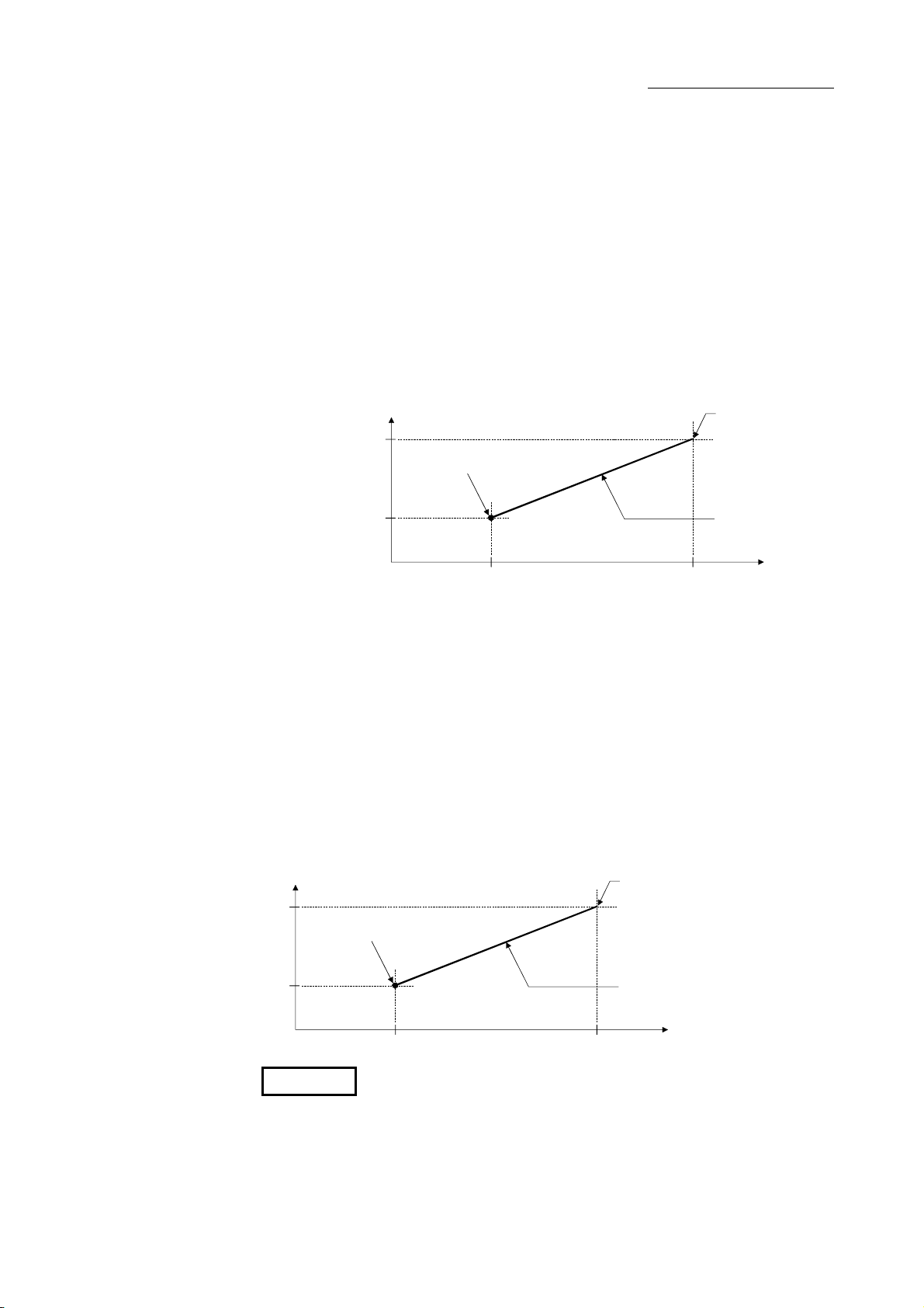
t
Chapter 1 Product Outline
(b) 2-axis linear interpolation control
(Note-1)
This controls interpolation along a linear locus from the start point address
(current stop position) defined by two axes.
[Control using the absolute system]
1) This performs linear interpolation using two axes from the start point
address to the specified address.
2) The start point address and the specified address determine the
direction of travel.
[Example]
The operation when the start point address is 800 for axis 1 and 2000
for axis 2 and the positioning address specified to 2000 for axis 1 and
8000 for axis 2, is shown below.
Axis 1
2000
Start point address
(2000, 800)
800
0
2000
Specified address
(8000, 2000)
Positioning operation
8000
Axis 2
[Control using the increment system]
1) This performs positioning to the composite position of the travel
direction and the travel increment specified by each axis from the start
point address.
2) The sign of the travel increment determines the direction of travel.
• For positive travel increment……Positioning in the positive direction
(direction of address increase)
• For negative travel increment……Positioning in the negative direction
(direction of address decrease)
[Example]
The operation when the start point address is 800 for axis 1 and 2000
for axis 2 and the positioning address specified to 1200 for axis 1 and
2000
6000 for axis 2, is shown below.
Axis 1
Start point address
(2000, 800)
End position when the travel incremen
is 1200 for axis 1 and 6000 for axis 2.
800
0
2000
Positioning operation
8000
Axis 2
REMARK
(Note-1): The interpolation speed during linear interpolation control can be selected
from "composite speed" and "reference axis speed" using the interpolation
speed designation method of detailed parameter 1. (Refer to Section 5.2.3
information about setting "[Pr.20] Interpolation speed designation method"
of the detailed parameter 1.)
1 - 10
Page 40

Chapter 1 Product Outline
(2) Circular interpolation control
(Note-1)
There are two types of circular interpolation controls: circular interpolation with a
specified sub point and circular interpolation with the specified center point.
(a) Circular interpolation with a specified sub point
Circular interpolation is performed using the specified endpoint address and
sub point (passing point) address.
Two methods are available: absolute system and increment system.
Forward
direction
Reverse
direction
Sub point
Start point
address
Reverse
direction
End point
Center point
(Calculated by the Simple Motion module)
Forward
direction
(b) Circular interpolation with the specified center point
Circular interpolation is performed using the specified endpoint address and
center point address.
Two methods are available: absolute system and increment system.
Also, the direction of movement can be selected from clockwise or
counterclockwise.
Forward
direction
End point
Reverse
direction
Stop position
Reverse
direction
Center point
Forward
direction
REMARK
(Note-1): The interpolation speed during circular interpolation control may only be
set to "composite speed" for the interpolation speed designation method of
detailed parameter 1. (Refer to Section 5.2.3 information about setting
"[Pr.20] Interpolation speed designation method" of the detailed parameter
1.)
1 - 11
Page 41

t
Chapter 1 Product Outline
(3) Fixed-feed control
This performs positioning for the specified increment of travel.
Positioning direction
[1-axis fixed-feed control]
Stop position
Forward directionReverse direction
Operation timing
V
Movement direction for
a negative movement amount
[2-axis fixed-feed control]
Forward
direction
Travel along
axis 1
Reverse
direction
Stop position
Reverse
direction
Movement direction for
a positive movement amount
Travel along axis 2
Forward
direction
Start
command
Start
ON
OFF
(4) Speed control
After command is executed, control continues with the command speed until the
stop command is input.
V
t
ON
Positioning start
signal
BUSY signal
Axis stop signal
OFF
ON
OFF
ON
OFF
(By the sequence
program creation)
1 - 12
Page 42

Chapter 1 Product Outline
(5) Speed-position switching control
This starts positioning under speed control, and switches to position control
according to the input of the Simple Motion module speed-position switching
signal and perform positioning for the specified increment of travel.
V
Specified travel
increment
Dwell time
t
(By the sequence
program creation)
Positioning start signal
BUSY signal
Speed-position switching
signal
Speed-position switching
enable flag
Speed control Position control
ON
OFF
ON
OFF
ON
OFF
ON
OFF
1 - 13
Page 43

Chapter 1 Product Outline
Independent positioning control and continuous positioning control
The Simple Motion module performs positioning according to the user-set positioning
data, which is a set of information comprised of the control method (position control,
speed control, speed-position switching control), positioning address, operation pattern,
and so on.
Up to 600 of positioning data are assigned respectively to positioning data Nos. 1 to
600 per axis and registered to the Simple Motion module.
The operation pattern set in each positioning data by the user determines whether to
perform positioning operation with one positioning data item or to perform continuous
positioning operation with multiple positioning data items.
(1) Independent positioning control (operation pattern = 00: positioning
complete)
The operation completed upon completion of positioning for the specified
positioning data. The positioning completion of this operation pattern is also used
as the operation pattern for the last positioning data of continuous positioning and
continuous path positioning.
V
Positioning complete (00)
Dwell time
t
ON
Positioning start signal
Positioning start
complete signal
BUSY signal
Positioning complete
signal
OFF
ON
OFF
ON
OFF
ON
OFF
(By the sequence
program creation)
1 - 14
Page 44

Chapter 1 Product Outline
(2) Continuous positioning control (operation pattern = 01: positioning
continue)
The operation stops temporarily upon the completion of positioning for the
specified positioning data, and then continues with the next positioning data
number.
This is specified when performing positioning in which the direction changes
because of multiple positioning data items having consecutive positioning data
numbers.
V
Positioning continue (01)
Address(+)
direction
Address(-)
direction
V
ON
Positioning start signal
Positioning start
complete signal
BUSY signal
Positioning complete
signal
OFF
ON
OFF
ON
OFF
OFF
Positioning continue (01)
Positioning
complete
(00)
ON
Dwell time
t
(By the sequence
program creation)
1 - 15
Page 45
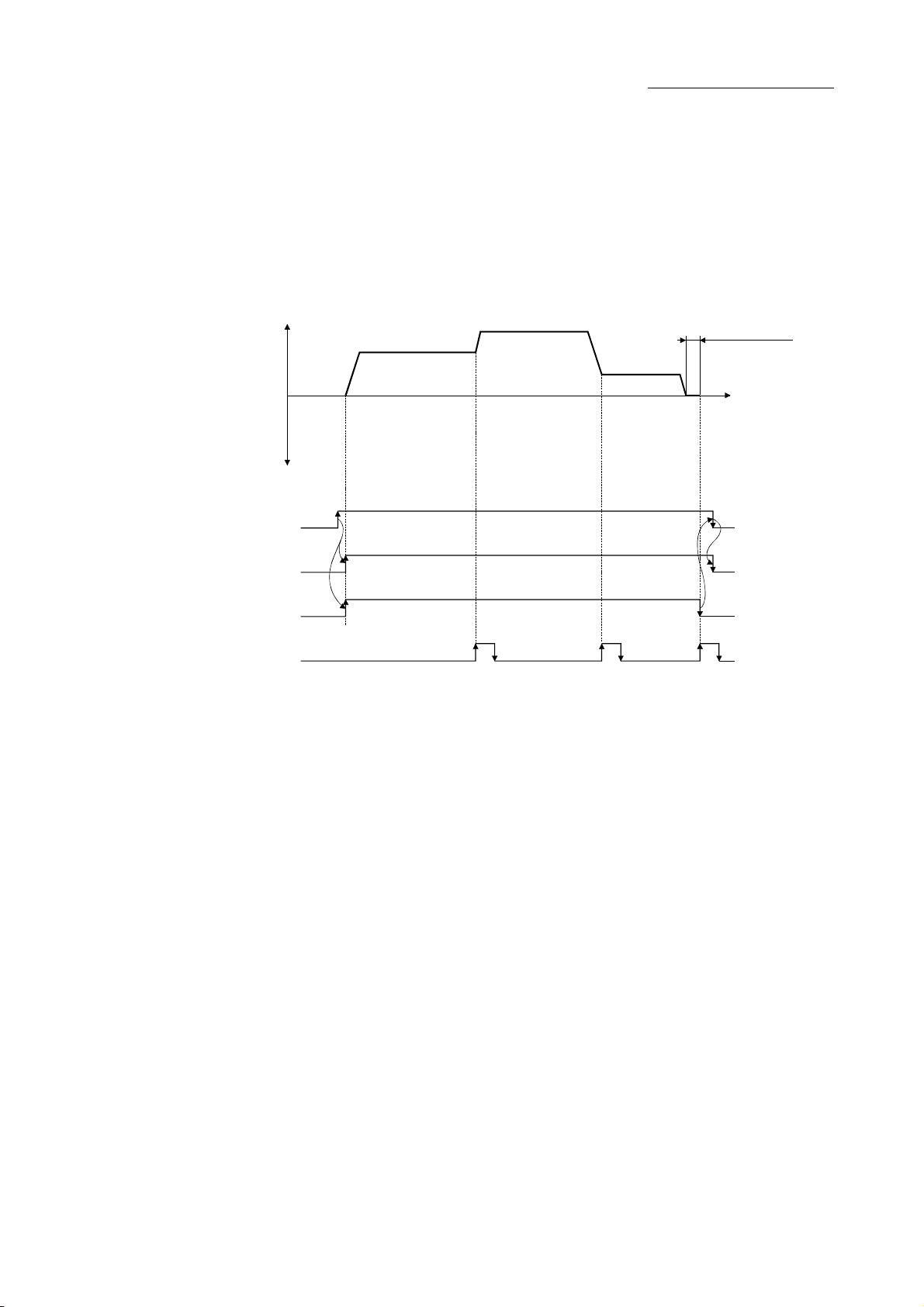
g
Chapter 1 Product Outline
(3) Continuous path control (operation pattern = 11: positioning
continue)
After executing positioning using the specified positioning data, the operation
changes its speed to that of the next positioning data number and continues
positioning.
This is specified when continuously executing multiple positioning data items
having consecutive positioning data numbers at a specified speed.
Address(+)
direction
Address(-)
direction
Positioning start signal
Positioning start
complete signal
BUSY signal
Positioning complete
si
nal
V
Positioning continue (11)
V
ON
OFF
ON
OFF
ON
OFF
OFF
Positioning continue (11)
ON
Positioning
complete
(00)
Dwell time
t
(By the sequence
program creation)
1 - 16
Page 46

Chapter 1 Product Outline
Block positioning control
Block positioning is a control that continuously executes the positioning of specified
blocks. One block equivalent to a series of positioning data up to the completion of
positioning (operation pattern = 00) by Independent or continuous positioning control.
A maximum of 50 blocks per axis can be specified.
Using a one-time start command from the PLC CPU or external, complex positioning
control can be performed.
The block positioning control can be performed by specifying the positioning start
number and positioning start information in the buffer memory.
Address(+)
direction
Address(-)
direction
V
Positioning complete (00)
V
One block
Positioning continue (01)
Positioning
continue (11)
One block One block
Positioning
complete (00)
Dwell time
Positioning
complete (00)
t
Positioning
continue (11)
Positioning start signal
Start complete signal
BUSY signal
Positioning complete
signal
ON
OFF
ON
OFF
ON
OFF
ON
OFF
1 - 17
Page 47

e
Chapter 1 Product Outline
Overview of acceleration/deceleration processing control
Acceleration/deceleration processing for the positioning processing, manual pulse-
generator processing, OPR processing and JOG processing is performed using the
user-specified method, acceleration time and deceleration time.
(1) Acceleration/deceleration method
There are two types of acceleration and deceleration processing: the trapezoidal
acceleration/deceleration processing method and S-curve acceleration/
deceleration processing method. A detailed parameter is used to set which
method is used. The specified acceleration/deceleration method is applied to all
accelerations and decelerations when starting and completing positioning
processing, OPR processing and JOG processing, as well as when changing the
speed.
(a) Trapezoidal acceleration/deceleration processing method
This is a method in which linear acceleration/deceleration is carried out
based on the acceleration time, deceleration time, and speed limit value set
by the user.
Velocity
Tim
(b) S-curve acceleration/deceleration processing method
This method reduces the load on the motor when starting and stopping.
This is a method in which acceleration/deceleration is carried out gradually,
based on the acceleration time, deceleration time, speed limit value, and Scurve ratio (1 to 100%) set by the user.
Velocity
Time
(2) Acceleration time, deceleration time, sudden-stop deceleration
time
(a) Four types each of the acceleration time and deceleration time for
positioning control can be set using basic parameters 2 and detailed
parameters 2.
• Acceleration time…….The time elapses before the speed of 0 reaches
the limit value.
• Deceleration time…….The time elapses before the speed at the limit
value reaches 0.
(b) The sudden-stop deceleration time (1 to 8388608 ms) is set using the
detailed parameters 2.
1 - 18
Page 48

1.1.5 Outline design of positioning system
The outline of the positioning system operation and design using the Simple Motion
module is shown below.
(1) Positioning system using Simple Motion module
Chapter 1 Product Outline
PLC
CPU Simple Motion module
Positioning
command
Control
command
OS
Monitor data
Read
and
write,
etc.
Interface
S
S
C
N
E
T
(
Positioning command
Control command
/
Monitor data
H
(
External input signal
I
of the servo amplifie r
/
F
SSCNET (/H)
S
S
+
Positioning
C
control
N
-
E
T
(
/
H
(
I
/
F
External input signal of servo amplifier (Refer to the servo
amplifier Instruction manual.)
FLS (Upper limit signal)
RLS (Lower limit signal)
DOG (Near-point dog signal)
Manual pulse generator/
Incremental synchronous encoder
A-phase/B-phase
External input signal (Refer to Section 3.4.2)
EMI (Forced stop input signal)
FLS (Upper limit signal)
RLS (Lower limit signal)
DI (External command signal/Switching signal)
STOP (STOP signal)
DOG (Near-point dog signal)
(Note): The external input signal of QD77MS, external input signal of servo amplifier,
or external input signal via CPU (buffer memory of QD77MS) can be used in
the parameter setting. (Refer to Section 5.2.3.)
+
-
Position feedback
+
Speed
control
-
Speed feedback
(Note)
(Note)
(Note)
(Note)
(Note)
(Note)
Current
control
Current feedback
Inverter
Interface
Servo
motorServo amplifier
M
PLG
Fig. 1.1 Outline of the operation of positioning system using Simple Motion module
1 - 19
Page 49

1.1.6 Communicating signals between QD77MS and each module
The outline of the signal communication between the Simple Motion module and PLC
CPU, GX Works2 and servo amplifier, etc., is shown below.
(GX Works2 communicates with the Simple Motion module via the PLC CPU to which
it is connected.)
(1) QD77MS2/QD77MS4
QD77MS2/QD77MS4
PLC CPU
Y0
X0
Y1
X1
Y8,YA,YC,YE
Y9,YB,YD,YF
Y14,Y15,Y16,Y17
Y10,Y11,Y12,Y13
X14,X15,X16,X17
XC,XD,XE,XF
X10,X11,X12,X13
Y4,Y5,Y6,Y7
PLC READY signal
READY signal
All axis servo ON signal
Synchronization flag
Forward run JOG start signal
Reverse run JOG start signal
Execution prohibition flag
Positioning start signal
Positioning complete signal
BUSY signal
Start complete signal
Axis stop signal
External
interface
Operating information of
the servo amplifier
Positioning command
Control command
Servo parameter
External input signal of
the servo amplifier
Manual pulse generator/
Incremental synchronous encoder
A-phase
Manual pulse generator/
Incremental synchronous encoder
B-phase
Chapter 1 Product Outline
SSCNET (/H)
Servo
amplifier
Manual pulse
generator/
Incremental
synchronous
encoder
X4,X5,X6,X7
X8,X9,XA,XB
Peripheral
device
interface
M code ON signal
Error detection signal
Data write/read
Parameter wr ite/read
Positioning data write/re ad
Block start data write/read
OPR operatio n (Test)
JOG operation, inching operation
(Test)
Positioning operation (Test)
Operation monitor
Interface
with
PLC CPU
Forced stop input signal
Upper limit signal
Lower limit signal
External command signal/
Switching signal
STOP signal
Near-point dog signal
External
input signal
GX Works2
POINT
When using the upper/lower limit signal, stop signal, near-point dog signal of the external
input signal via CPU, use the buffer memory in " External input signal operation
Cd.44
device".
1 - 20
Page 50

PLC CPU
Y0
X0
Y1
X1
Y10 to Y1F
X10 to X1F
(2) QD77MS16
PLC READY signal
READY signal
All axis servo ON signal
Synchronization flag
Positioning start signal
BUSY signal
Data write/read
Parameter write/read
Positioning data write/read
Block start data write/read
Interface
with
PLC CPU
QD77MS16
External
interface
Chapter 1 Product Outline
SSCNET (/H)
Operating information of
the servo amplifier
Positioning command
Control command
Servo parameter
External input signal of
the servo amplifier
Manual pulse generator/
Incremental synchronous encoder
A-phase
Manual pulse generator/
Incremental synchronous encoder
B-phase
Forced stop input signal
Upper limit signal
Lower limit signal
External command signal/
Switching signal
STOP signal
Near-point dog signal
Servo
amplifier
Manual pulse
generator/
Incremental
synchronous
encoder
External
input signal
Peripheral
device
interface
GX Works2
OPR operation (Test)
JOG operation, inching operation
(Test)
Positioning operation (Test)
Operation monitor
POINT
(1) For QD77MS16, M code ON signal, error detection signal, start complete signal and
positioning complete signal are assigned to the bit of " Status".
Md.31
(2) For QD77MS16, axis stop signal, forward run JOG start signal, reverse run JOG start
signal, execution prohibition flag are assigned to the buffer memory to .
Cd.180 Cd.183
(3) When using the upper/lower limit signal, stop signal, near-point dog signal of the
external input signal via CPU, use the buffer memory in " External input signal
Cd.44
operation device".
1 - 21
Page 51

Chapter 1 Product Outline
Simple Motion module PLC CPU
The Simple Motion module and PLC CPU communicate the following data.
Direction
Communication
Control signal
Data (read/write)
Simple Motion module PLC CPU PLC CPU Simple Motion module
Signal indicating Simple Motion module
state
• READY signal
• BUSY signal
etc.
• Parameter
• Positioning data
• Block start data
• Control data
• Monitor data
Signal related to commands
• PLC READY signal
• All axis servo ON signal
• Positioning start signal
etc.
• Parameter
• Positioning data
• Block start data
• Control data
Refer to Section 3.3 "Specifications of input/output signals with PLC CPU" for details.
Simple Motion module GX Works2
The Simple Motion module and GX Works2 communicate the following data via the
PLC CPU.
Direction
Communication
Data (read/write)
Test operation –
Operation monitor • Monitor data –
Simple Motion module
• Parameter
• Positioning data
GX Works2 GX Works2 Simple Motion module
• Parameter
• Positioning data
• OPR control start command
• Positioning control start command
• JOG/Inching operation start command
• Teaching start command
• Manual pulse generator operation
enable/disable command
Simple Motion module Servo amplifier
The Simple Motion module and servo amplifier communicate the following data via
Communication
SSCNET /H
SSCNET
the SSCNET
Direction
• Positioning commands
• Control commands
• Servo parameter
.
(/H)
Simple Motion module
Servo amplifier
Servo amplifier
Simple Motion module
• Operating information of the servo
amplifier
• Servo parameter
• External input signal of the servo amplifier
1 - 22
Page 52
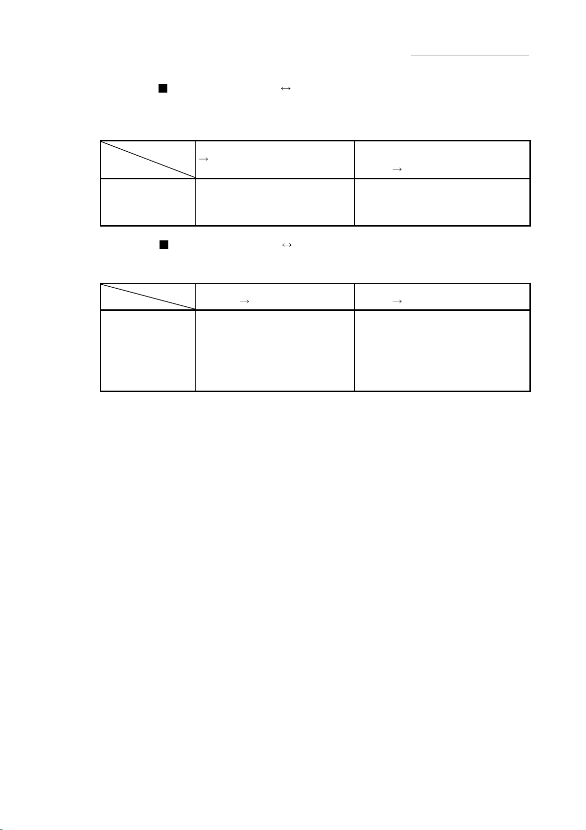
Chapter 1 Product Outline
Simple Motion module Manual pulse generator/Incremental synchronous
encoder
The Simple Motion module and manual pulse generator/incremental synchronous
Communication
Pulse signal –
encoder communicate the following data via the external input connection connector.
Direction
Simple Motion module
Manual pulse generator/Incremental
synchronous encoder
Manual pulse generator/Incremental
synchronous encoder
Simple Motion module
• Manual pulse generator/Incremental
synchronous encoder A-phase
• Manual pulse generator/Incremental
synchronous encoder B-phase
Simple Motion module External signal
The Simple Motion module and external signal communicate the following data via
Communication
Control signal –
the external input connection connector.
Direction
Simple Motion module
External signal
External signal
Simple Motion module
Forced stop input signal
External command signal/switching signal
Upper limit signal
Lower limit signal
Stop signal
Near-point dog signal
1 - 23
Page 53

1.2 Flow of system operation
1.2.1 Flow of all processes
Chapter 1 Product Outline
DesignPreparationOperationMaintenance
The positioning control processes, using the Simple Motion module, are shown below.
Servo
amplifiers, etc.
1)
GX Works2
Understand the functions and performance, and determine the
positioning operation method (system design)
PLC CPU
2)
QD77MS
Installation, wiring
3)
Setting of parameters
and data for QD77MS
4)
Creation of sequence
program for operation
Writing of program
Writing of setting data
6)
5)
7)
Monitoring and
debugging of setting
data with test function
Connection confirmation
8)
Monitoring and
debugging of
operation program
Monitor
9)
10)
11)
Test operation
Actual operation
Maintenance
Disposal
1 - 24
Page 54

Chapter 1 Product Outline
Details Reference
Understand the product functions and usage methods, the configuration devices
1)
and specifications required for positioning control, and design the system.
Install the Simple Motion module onto the base unit, wire the Simple Motion
module and external connection devices (servo amplifier, etc.) and wire the PLC
2)
CPU and peripheral devices.
Using GX Works2, set the servo parameters, parameter, positioning data, block
3)
start data and condition data required for the positioning control to be executed.
4) Using GX Works2, create the sequence program required for positioning operation.
Write the parameters and positioning data, etc., created with GX Works2 into the
5)
Simple Motion module.
6) Using GX Works2, write the created sequence program into the PLC CPU.
Carry out test operation and adjustments in the test function of GX Works2 to
check the connection with the Simple Motion module and external connection
7)
device, and to confirm that the designated positioning operation is executed
correctly. (Debug the set "parameters" and "positioning data", etc.)
Carry out test operation and adjustment to confirm that the designated positioning
8)
operation is executed correctly. (Debug the created sequence program.)
Actually operate the positioning operation. At this time, monitor the operation state
9)
as required. If an error or warning occurs, remedy.
10) Maintenance of the Simple Motion module as required.
11) Dispose of the Simple Motion module.
The following work is carried out with the processes shown on the previous page.
Chapter 1
Chapter 2
Chapter 3
Chapter 8 to Chapter 14
Chapter 4
Chapter 5
Chapter 8 to Chapter 14
Simple Motion Module Setting
Tool Help
Chapter 6
GX Works2 Version1
Operating Manual (Common)
Chapter 7
Simple Motion Module Setting
Tool Help
Chapter 7
GX Works2 Version1
Operating Manual (Common)
Chapter 14
Simple Motion Module Setting
Tool Help
GX Works2 Version1
Operating Manual (Common)
Chapter 5
Chapter 16
Simple Motion Module Setting
Tool Help
GX Works2 Version1
Operating Manual (Common)
Chapter 4
Chapter 4
1 - 25
Page 55

1.2.2 Outline of starting
The outline for starting each control is shown with the following flowchart.
(It is assumed that each module is installed, and the required system configuration,
etc., has been prepared.)
Chapter 1 Product Outline
Flow of starting
Preparation
Control
functions
Positioning
parameters
OPR
parameters
Expansion
parameters
Servo
parameters
PLC READY
All axis
servo ON
Positioning
data
Installation and connection of module
Setting of hardware
Major positioning
control
Position control
Speed control
Speed-position
switching control
Position -speed
switching control
Other control
Set the positioning data.
( to , to )Da.1 Da.10 Da.20 Da.22
High-level positioning
control
Block start (Normal start)
Condition start
Wait start
Simultaneous start
Repeated start
Set the positioning parameters. ( to , to , , , ) Pr.1 Pr.42 Pr.84Pr.80 Pr.89 Pr.90 Pr.95
( to , , )Pr.86
OPR control
Machine OPR control
Fast OPR control
Set the OPR parameters.
Pr.87Pr.43 Pr.57
Set the expansion parameters. ( to , ,
Set the servo parameters. ( , PA, PB, PC, PD, PE, PS, PF, Po, PL)
Turn the PLC READY signal ON (Y0 ON)
Turn the All axis servo ON signal ON (Y1 ON)
JOG operation
Pr.100
Manual control
Inching operation
Manual pulse generator
operation
Pr.97 Pr.114
, ) Pr.91 Pr.94 Pr.96
Block start
data
Control data
Start signal
Control start
Control end
Set the block start data.
( to , to )Da.11
Set the positioning starting point No.
Input the start signal.
Method (1) Turn ON the QD77MS start signal from the PLC CPU
Method (2) Issue the ZP.PSTRT instruction from the PLC CPU.
Method (3) Turn the QD77MS external command signal ON
Da.19 Da.23 Da.26
Set the positioning start No. ( )
)
(
Cd.4
Cd.3
Operation
Stop
Set the JOG speed.
(
)
Cd.17
Set a value except "0" to the
inching movement amount.
Set "0" to the inching
movement amount.
)Cd.16
(
Turn the QD77MS JOG
start signal ON from the
PLC CPU
Set "1" to the manual pulse
generator enable flag.
(
)
(
Cd.16
Set the manual pulse generator
1 pulse input magnification.
Cd.20
(
Operate the
manual pulse
generator
)Cd.21
)
1 - 26
Page 56

Speed-torque control
(Speed control) (Torque control)
Expansion control
Setting method
(Continuo us operation
to torque control)
Chapter 1 Product Outline
: Indicates the sequence program that must be created.
Set the acceleration/
deceleration time at
speed control mode.
Cd.141 Cd.142
( ,
Set the torque time
constant (forward
direction/reverse
direction) and speed
)
limit value at torque
control mode.
Cd.144 Cd.146
( to
Set the acceleration/
deceleration time,
torque time constant
(forward direction/
reverse direction) and
speed limit value at
continuous operation
)
to torque control
mode.
Cd.147 Cd.149
Cd.151 Cd.152
to ,
to
<GX Works2>
Set with Simple Motion Module
Setting Tool
Set the parameter and data for executing
main function, and the sub functions that
need to be set beforehand.
<GX Works2>
Set with sequence program for
setting data
Create this program as necessary.
<GX Works2>
Create sequence program for
executing main function
Create sequence program for
outputting control signals,
such as start signal, to
QD77MS.
Write
Write
Operation sequence
program
PLC CPU
Write
QD77MS
PLC CPU
Write
Switch the control mode. ( , )Cd.138 Cd.139
Set the command
speed at speed
control mode
( )Cd.140
Set the command
torque at torque
control mode
( )Cd.143
Set the switching conditions
at continuous operation to
torque control mode
( to
Cd.153 Cd.154
Set the target torque at
continuous operation
to torque control mode
(
)
)Cd.150
1 - 27
<GX Works2>
Speed change
Current value changing
Torque limit
Restart, etc.
Create a sequence
program for the sub
functions.
Page 57

1.2.3 Outline of stopping
Chapter 1 Product Outline
Stop cause
Forced stop
Fatal stop
(Stop group 1)
Emergency
stop
(Stop group 2)
Each control is stopped in the following cases.
(1) When each control is completed normally.
(2) When the servo amplifier power supply OFF.
(3) When a PLC CPU error occurs.
(4) When the PLC READY signal is turned OFF.
(5) When an error occurs in the Simple Motion module.
(6) When control is intentionally stopped (Stop signal from PLC CPU turned ON or
The outline for the stopping process in these cases is shown below. (Excluding (1) for
normal stopping.)
Refer to Section 12.1 "Speed-torque control" for the stop processing during the speed
control mode, torque control mode or continuous operation to torque control mode.
"Forced stop
input signal"
OFF from an
external
device
Servo
READY OFF
• Servo
amplifier
power suppl y
OFF
• Servo alarm
• Forced stop
input to servo
amplifier
Hardware
stroke limit
upper/lower
limit error
occurrence
Error occurs
in PLC CPU
PLC READY
signal OFF
Error in test
mode
Stop signal of external input signal turned ON, etc.).
Stop process
Stop
axis
All
axes
Each
axis
Each
axis
All
axes
M code
ON signal
after stop
No
change
No
change
No
change
No
change
Turns
OFF
No
change
Axis
operation
status
after
stopping
([Md.26])
Servo
OFF
Servo
amplifier
has not been
connected
Error
Servo
OFF
Error
Error
OPR control
Machine
OPR
control
control
Fast
OPR
Major
positioning
control
Servo OFF or free run
(The operation stops with dynamic brake.)
Deceleration stop/sudden stop
(Select with "[Pr.37] Stop group 1 sudden stop
selection".)
Deceleration stop/sudden stop
(Select with "[Pr.38] Stop group 2 sudden stop
selection".)
High-level
positioning
control
Manual control
JOG/
Inching
operation
Manual
pulse
generator
operation
Deceleration
stop
Deceleration
stop
1 - 28
Page 58

Chapter 1 Product Outline
Axis
Stop cause
Stop
axis
M code
ON signal
after stop
operation
status
after
stopping
([Md.26])
OPR control
Machine
OPR
control
Fast
OPR
control
Major
positioning
control
Axis error
detection
(Error other
Relatively safe
stop
(Stop group 3)
than stop
group 1 or 2)
(Note-1)
"Stop" input
from
GX Works2
"Axis stop
Each
axis
No
change
Error
Deceleration stop/sudden stop
(Select with "[Pr.39] Stop group 3 sudden stop
selection".)
signal" ON
from PLC
Intentional stop
(Stop group 3)
CPU
"Stop signal"
Each
axis
No
change
Stopped
(Standby)
of external
input signal
(Note-1): If an error occurs in a positioning data due to an invalid setting value, when the continuous positioning control uses multiple
positioning data successively, it automatically decelerates at the previous positioning data. It does not stop suddenly even the
setting value is sudden stop in stop group 3. If any of the following error occurs, the operation is performed up to the positioning
data immediately before the positioning data where an error occurred, and then stops immediately.
• No command speed (Error code: 503)
• Outside linear movement amount range (Error code: 504)
• Large arc error deviation (Error code: 506)
• Software stroke limit + (Error code: 507)
• Software stroke limit - (Error code: 508)
• Sub point setting error (Error code: 525)
• End point setting error (Error code: 526)
• Center point setting error (Error code: 527)
• Outside radius range (Error code: 544)
• Illegal setting of ABS direction in unit of degree (Error code: 546)
ON
Stop process
High-level
positioning
control
Manual control
JOG/
Inching
operation
Manual
pulse
generator
operation
Deceleration
stop
REMARK
Provide the emergency stop circuits outside the servo system to prevent cases
where danger may result from abnormal operation of the overall system in the event
of an external power supply fault or servo system failure.
1 - 29
Page 59

4
4
1.2.4 Outline for restarting
When a stop cause has occurred during operation with position control causing the
axis to stop, positioning to the end point of the positioning data can be restarted from
the stopped position by using the "[Cd.6] Restart command".
If issued during a continuous positioning or continuous path control operation, the
restart command will cause the positioning to be re-executed using the current position
(pointed by the positioning data No. associated with the moment when the movement
was interrupted) as the start point.
Axis 1
When "[Cd.6] Restart command" is ON
(1) If the "[Md.26] Axis operation status" is stopped, positioning to the end point of
(2) When "[Md.26] Axis operation status" is not stopped, the warning "Restart not
Chapter 1 Product Outline
the positioning data will be restarted from the stopped position regardless of
the absolute system or incremental system.
possible" (warning code: 104) will be applied, and the restart command will be
ignored.
(a) The restart operation when the axis 1 movement amount is 300 and the
axis 2 movement amount is 600 is shown below.
Axis 1
Stop position due to stop cause
00
Start point
address
200
100
100 300 700
Designated end
point position
Axis 2
Restart
Stop position due to stop cause
400
200
100
100 300 700
Stop position
after restart
Operation during
restart
Axis 2
REMARK
If the positioning start signal/external command signal is turned ON while the
"[Md.26] Axis operation status" is standby or stopped, positioning will be restarted
from the start of the positioning start data regardless of the absolute system or
incremental system. (
positioning start") (Same as normal positioning.)
[Example for incremental system]
(a) The positioning start operation, which stops the positioning control while
executing that the axis 1 movement amount is 300 and the axis 2
Axis 1
Stop position due to stop cause
00
Start point
address
200
100
100 300 700
movement amount is 600, is shown below.
Designated end
point position
: When the external command signal is set to "External
Axis 1
Axis 2
Stop position due to stop cause
500
Positioning
start
200
100
100 300 900
Stop position
after restart
Operation during
positioning start
Axis 2
1 - 30
Page 60

Chapter 2 System Configuration
Chapter 2 System Configuration
2
In this chapter, the general image of the system configuration of the positioning control
using Simple Motion module, the configuration devices, applicable CPU and the
precautions of configuring the system are explained.
Prepare the required configuration devices to match the positioning control system.
2.1 General image of system ........................................................................................ 2- 2
2.2 Component list ........................................................................................................ 2- 4
2.3 Applicable system ................................................................................................... 2- 8
2.4 How to check the function version and SERIAL No. ............................................... 2-10
2.5 Restrictions by the SERIAL No. and version .......................................................... 2-11
2 - 1
Page 61

2.1 General image of system
The general image of the system, including such as the QD77MS, PLC CPU and
peripheral devices is shown below.
Main base unit
Chapter 2 System Configuration
Power supply module
USB cable
Ethernet cable
RS-232 cable
CPU module
External input
signal cable
QD77MS
QD77MS4
RUN
AX1
AX2
AX3
ERR.
AX4
QD77MS4
AX1
AX3
AX2
AX4
Expansion cable
SSCNET
cable
Expansion system
External input signals of servo amplifier
Upper stroke limit
Lower stroke limit
Near-point dog
Personal computer
Manual pulse generator
/Incremental synchronous encoder 1
External command signal
/Switching signal (4 points)
Upper stroke limit (4 points)
Lower stroke limit (4 points)
Near-point dog signal (4 points)
Stop signal (4 points)
Forced stop input (24VDC)
2 - 2
Servo
motor
Servo
motor
MR-J3(W)-_B type servo amplifier
MR-J4(W)-_B type servo amplifier
MR-JE-_B type servo amplifier
Servo driver VCII series manufactured
by Nikki Denso Co., Ltd.
Inverter FR-A700 series
QD77MS2 :Up to 2 axes
QD77MS4 :Up to 4 axes
QD77MS16 :Up to 16 axes
Synchronous encoder via servo amplifier
Q171ENC-W8:
Up to 4 modules via MR-J4-_B-RJ
Servo
motor
Page 62

Chapter 2 System Configuration
REMARK
(Note-1): Refer to Section "2.3 Applicable system" for the CPU modules that can be used.
(Note-2): Refer to the CPU module User's Manual for the base units that can be used.
(Note-3): The external input signal cannot be used depending on the connected device.
Confirm the specification of the connected device.
2 - 3
Page 63

Chapter 2 System Configuration
2.2 Component list
The positioning system using the Simple Motion module is configured of the following
No. Part name Type Remarks
Simple Motion
1
module
2 Personal computer
3 RS-232 cable
4 USB cable –
5 Ethernet cable –
6 Servo amplifier –
Manual pulse
7
generator
SSCNET
8
cable
External input signal
9
cable
(Note-1): The cables for connecting between the Simple Motion module and servo amplifiers. Refer to each servo amplifier instruction
manual for details.
[SSCNET
MR-J3BUS_M
(Standard cord for inside
panel)
MR-J3BUS_M-A
(Standard cable for outside
panel)
MR-J3BUS_M-B
(Long distance cable)
_= Cable length
(Note-1)
(Note-1)
(015: 0.15m (0.49ft.), 03: 0.3m (0.98ft.), 05: 0.5m (1.64ft.), 1: 1m (3.28ft.), 3: 3m (9.84ft.), 5: 5m (16.40ft.),
10: 10m (32.81ft.), 20: 20m (65.62ft.), 30: 30m (98.43ft.), 40: 40m (131.23ft.), 50: 50m (164.04ft.) )
devices.
QD77MS2
QD77MS4
QD77MS16
Personal
computer which
supports
Windows
R
QC30R2
–
–
–
cable]
Model name Cable length [m(ft.)] Description
MR-J3BUS015M 0.15 (0.49)
MR-J3BUS03M 0.3 (0.98)
MR-J3BUS05M 0.5 (1.64)
MR-J3BUS1M 1 (3.28)
MR-J3BUS3M 3 (9.84)
MR-J3BUS5M-A 5 (16.40)
MR-J3BUS10M-A 10 (32.81)
MR-J3BUS20M-A 20 (65.62)
MR-J3BUS30M-B 30 (98.43)
MR-J3BUS40M-B 40 (131.23)
MR-J3BUS50M-B 50 (164.04)
QD77MS
Number of control axes
MS: SSCNET (/H)model
(Prepared by user)
Refer to the "GX Works2 Version1 Operating Manual (Common)" for details.
(Prepared by user)
An RS-232 cable is needed for connecting the CPU module with a personal
computer.
Refer to the "GX Works2 Version1 Operating Manual (Common)" for details.
(Prepared by user)
A USB cable is needed for connecting the CPU module with a personal
computer.
Refer to the "GX Works2 Version1 Operating Manual (Common)" for details.
(Prepared by user)
An Ethernet cable is needed for connecting the CPU module with a personal
computer. Refer to the "GX Works2 Version1 Operating Manual (Common)"
for details.
(Prepared by user)
(Prepared by user)
Recommended: MR-HDP01 (Manufactured by Mitsubishi Electric
Corporation)
(Prepared by user)
Cables are needed for connecting the Simple Motion module with a servo
amplifier, or between servo amplifiers.
(Prepared by user)
Cables are needed for connecting the Simple Motion module with an external
device.
(Prepare them referring to the manuals for the connected devices and
information given in 3.4.2 of this manual.)
• Simple Motion module
MR-J4(W)-B/MR-JE-B/MR-J3(W)-B
• MR-J4(W)-B/MR-JE-B/MR-J3(W)-B
MR-J4(W)-B/MR-JE-B/MR-J3(W)-B
2 - 4
Page 64

Chapter 2 System Configuration
[External input wiring connector]
Part name Specification
Applicable connector A6CON1, A6CON2, A6CON3, A6CON4 (Sold separately)
Applicable wire size
2
0.3mm
(When A6CON1 and A6CON4 are used), AWG28 to AWG24 (When A6CON2 is used),
AWG28 (twisted)/AWG30 (single wire) (When A6CON3 is used)
Specifications of recommended manual pulse generator
Item Specification
Model name MR-HDP01
Ambient temperature -10 to 60°C (14 to 140°F )
Pulse resolution 25PLS/rev (100 PLS/rev after magnification by 4)
Output method
Power supply voltage 4.5 to 13.2VDC
Current consumption 60mA
Output level
"H" level : Power supply voltage
"L" level : 0.5V or less (with maximum leading-in)
Life time 1000000 revolutions (at 200r/min)
Permitted axial loads
Weight 0.4 [kg]
Number of max. revolution Instantaneous Max. 600r/min. normal 200r/min
Pulse signal status 2 signals: A phase, B phase, 90° phase difference
Start friction torque 0.06N•m (20°C (68°F))
(Note-1): If a separate power supply is used, use a stabilized power supply of voltage 5VDC ± 0.25V.
Voltage-output, Output current Max. 20mA
(Note-1)
-1V or more (in no load)
Radial load: Max. 19.6N
Thrust load: Max. 9.8N
2 - 5
Page 65

Chapter 2 System Configuration
Serial absolute synchronous encoder specifications
Item Specifications
Model name
Ambient temperature -5 to 55°C (23 to 131°F)
Resolution 4194304PLS/rev
Transmission method
Direction of increasing addresses CCW (viewed from end of shaft)
Protective construction
Permitted speed at power ON 3600r/min
Permitted speed at power OFF
(Note-2)
Permitted axial loads Radial load : Up to 19.6N, Thrust load : Up to 9.8N
Runout at input shaft tip
Start friction torque 0.04N•m (20°C (68°F))
Recommended coupling Bellows coupling
Permitted angular acceleration 40000rad/s2
Vibration resistance 5G (50 to 200Hz)
Shock resistance 50G (11ms or less)
Internal current consumption [A] 0.2
Mass [kg] 0.6
Connecting cable [m(ft.)]
Communications method Differential driver/receiver
Transmission distance Up to 50m (164.04ft.)
(Note-1): When "o-ring" is required, please purchase separately by customers.
(Note-2): If it exceeds a permitted speed at power OFF, a position displacement is generated.
(_=Cable length : 2 (6.56), 5 (16.40), 10 (32.81),
(IP67: Except for the shaft-through portion.)
Q171ENC-W8
Serial communications
(Connected to MR-J4-_B-RJ)
Dustproof/Waterproof
500r/min
0.02mm(0.00079 inch) or less,
(15mm(0.59 inch) from tip)
Q170ENCCBL_M
20 (65.62), 30 (98.43), 50 (164.04))
(Note-1)
2 - 6
Page 66

Specifications of serial absolute synchronous encoder input (CN2L) of servo amplifier
Item Specifications
Applicable types Q171ENC-W8
Applicable signal types Differential-output type : (SN75C1168 or equivalent)
Transmission method Serial communications
Synchronous method Counter-clock-wise (viewed from end of shaft)
Communication speed 2.5Mbps
Position detection method Absolute (ABS) method
Resolution 4194304PLS/rev (22bit)
Number of modules 1/module (MR-J4-_B-RJ)
External connector type 20 pin connector
Applicable connector for
the external connection
Applicable wire J14B103715-00 12 pairs
Connecting cable [m(ft.)]
Cable length Up to 50m (164.04ft.)
Back up the absolute position. Depends on the battery (MR-BAT6V1SET).
Battery service life time
(value in actual)
(_=Cable length: 2 (6.56), 5 (16.40), 10 (32.81), 20 (65.62),
30 (98.43), 50 (164.04))
10000[h] (When MR-BAT6V1SET is used while the device is turned OFF
at the ambient temperature of 25°C (77°F))
MR-J3CN2 (Optional)
Q170ENCCBL_M-A
Chapter 2 System Configuration
2 - 7
Page 67

2.3 Applicable system
(1) Number of applicable modules
Applicable CPU module
CPU type CPU model Main base unit Extension base unit
Basic model
QCPU
High
performance
model QCPU
Process
CPU
Redundant
CPU
PLC
CPU
Universal
model QCPU
Universal
model
QnUDV
(High speed
type CPU)
Chapter 2 System Configuration
Pay attention to the power supply capacity before mounting modules because
power supply capacity may be insufficient depending on the combination with
other modules or the number of mounted modules.
If the power supply capacity is insufficient, change the combination of the
modules.
(a) When mounted with a CPU module
No. of modules
(Note-1)
Q00JCPU Up to 8 modules
Q00CPU
Q01CPU
Q02CPU
Q02HCPU
Q06HCPU
Q12HCPU
Q25HCPU
Q02PHCPU
Q06PHCPU
Q12PHCPU
Q25PHCPU
Q12PRHCPU
Q25PRHCPU
Q00UJCPU Up to 8 modules
Q00UCPU
Q01UCPU
Q02UCPU Up to 36 modules
Q03UDCPU
Q04UDHCPU
Q06UDHCPU
Q10UDHCPU
Q13UDHCPU
Q20UDHCPU
Q26UDHCPU
Q03UDECPU
Q04UDEHCPU
Q06UDEHCPU
Q10UDEHCPU
Q13UDEHCPU
Q20UDEHCPU
Q26UDEHCPU
Q03UDVCPU
Q04UDVCPU
Q06UDVCPU
Q13UDVCPU
Q26UDVCPU
Up to 24 modules
Up to 64 modules
Up to 64 modules
Up to 53 modules
Up to 24 modules
Up to 64 modules
Up to 64 modules
(Note-1): Limited within the range of I/O points for the CPU module.
(Note-2): Can be installed to any I/O slot of a base unit.
Base unit
(Note-2)
: Applicable, : N/A
2 - 8
Page 68

Chapter 2 System Configuration
(b) Mounting to a MELSECNET/H remote I/O station
Applicable
network module
QJ72LP25-25
QJ72LP25G
QJ72BR15
No. of modules
(Note-1)
Max. 64 modules
(Note-1): Within the I/O point range of network module only.
(Note-2): It can be installed in any of the I/O slots of installable base unit.
Main base unit of
remote I/O station
: Installation possible, : Installation not possible
Base unit
(Note-2)
Extension base unit of
remote I/O station
REMARK
The basic model QCPU cannot configure the MELSECNET/H remote I/O network.
(2) Compatibility with multiple CPU system
When using the QD77MS in a multiple CPU system, refer to the QCPU User's
Manual (multiple CPU system).
(3) Programming tool
The applicable programming tool's versions of the QD77MS are shown below.
(For the applicable programming tool's versions of the CPU module, refer to the
"QCPU User's Manual (Hardware Design, Maintenance and Inspection)".)
Version
QD77MS2
QD77MS16
GX Works2 MR Configurator2
Version 1.77F or later Version 1.09K or later QD77MS4
REMARK
QD77MS cannot be supported with GX Developer, GX Configurator-QP and
MR Configurator.
Use GX Works2 and MR Configurator2 to use QD77MS.
2 - 9
Page 69

2.4 How to check the function version and SERIAL No.
The function version and the SERIAL No. of the Simple Motion module can be
checked in the following methods.
(1) Confirming the serial number on the rating plate
The rating plate is situated on the side face of the Simple Motion module.
MELSEC-Q
MITSUBISHI
SIMPLE MOTION UNIT
PASSED
MODEL QD77MS4
Chapter 2 System Configuration
24VDC 0.1A CLASS2
SERIAL
MITSUBISHI ELECTRIC CORPORATION
See QD77MS4 instruction manual.
Vovez QD77MS mode d' emplol
131210000000 000 - B
US LISTEDC
IND. CONT.EQ.80M1
KCC-REI-MEKTC510A796G51
DATE:2014-06
5VDC 0.75A
MADE IN JAPAN
SERIAL No.
Function version
(2) Checking on the front of the module
The serial No. on the rating plate is also indicated on the front of the module
(lower part).
QD77MS4
RUN
AX1
AX2
AX3
ERR.
AX4
QD77MS4
AX1
AX3
AX2
AX4
131210000000000-B
SERIAL No. Function version
(3) Confirming by the software
Check the function version and SERIAL No. in "Product Information" displayed
on System monitor "Product Information List" of GX Works2.
2 - 10
Page 70

Chapter 2 System Configuration
2.5 Restrictions by the SERIAL No. and version
There are restrictions in the function that can be used by the SERIAL No. of the Simple
Motion module and the version of GX Works2.
Function
Inverter FR-A700 series 14062 or later 1.492N or later 14062 or later 1.492N or later Appendix 6.3
Driver communication function
Synchronous encoder via servo
amplifier
Mark detection function
(Changes latch data range upper
limit value/lower limit value during
mark detection.)
External command signal
compensation valid/invalid setting
Operation cycle setting for
QD77MS2/QD77MS4
Servo driver (VCII series)
manufactured by Nikki Denso Co.,
Ltd. (SSCNET
MR-JE-B 16102 or later 1.525X or later 16102 or later 1.525X or later Appendix 6.3
Hot line forced stop function 16102 or later — 16102 or later — Section 14.15
(Note-1): The serial number can be checked on the "Product Information List" screen in GX Works2.
(Note-2): "MELSEC-Q/L QD77MS/QD77GF/LD77MS/LD77MH Simple Motion Module User’s Manual (Synchronous Control)"
/H)
The combination of each version and function are shown below.
QD77MS2/QD77MS4 QD77MS16
First five digits of
SERIAL No.
(Note-1)
15042 or later 1.492N or later 15042 or later 1.492N or later
15062 or later 1.493P or later — —
16012 or later 1.507D or later 16012 or later 1.507D or later Appendix 6.1
GX Works2
First five digits of
SERIAL No.
(Note-1)
GX Works2
Reference
Section 14.9
(Note-2)
Section 14.10
Section 5.2.7
Section 5.2.7
Section 5.6.1
2 - 11
Page 71

MEMO
Chapter 2 System Configuration
2 - 12
Page 72

Chapter 3 Specifications and Functions
Chapter 3 Specifications and Functions
3
The various specifications of the Simple Motion module are explained in this chapter.
The "Performance specifications", "List of functions", "Specifications of input/output
signals with PLC CPU", and "Specifications of interfaces with external devices", etc.,
are described as information required when designing the positioning system.
Confirm each specification before designing the positioning system.
3.1 Performance specifications ..................................................................................... 3- 2
3.2 List of functions ....................................................................................................... 3- 4
3.2.1 QD77MS control functions ......................................................................... 3- 4
3.2.2 QD77MS main functions ............................................................................ 3- 7
3.2.3 QD77MS sub functions .............................................................................. 3- 9
3.2.4 QD77MS common functions ...................................................................... 3-11
3.2.5 Combination of QD77MS main functions and sub functions ..................... 3-14
3.3 Specifications of input/output signals with PLC CPU .............................................. 3-16
3.3.1 List of input/output signals with PLC CPU ................................................. 3-16
3.3.2 Details of input signals (QD77MS
3.3.3 Details of output signals (PLC CPU
3.4 Specifications of interfaces with external devices ................................................... 3-23
3.4.1 Electrical specifications of input signals ..................................................... 3-23
3.4.2 Signal layout for external input connection connector ............................... 3-25
3.4.3 List of input signal details ........................................................................... 3-27
3.4.4 Interface internal circuit .............................................................................. 3-30
3.5 External circuit design ............................................................................................. 3-34
PLC CPU) ...................................... 3-19
QD77MS) .................................... 3-21
3 - 1
Page 73

(Note-1)
3.1 Performance specifications
Chapter 3 Specifications and Functions
Model
Item
Number of control axes 2 axes 4 axes 16 axes
Operation cycle 0.88ms/1.77ms
Interpolation function
Control system
Control unit mm, inch, degree, PLS
Positioning data
Execution data backup function
Positioning system
Positioning range
Positioning
Speed command
Acceleration/
deceleration process
Acceleration/
deceleration time
Sudden stop
deceleration time
PTP (Point To Point) control, path control (both linear and arc can be set), speed control,
speed-position switching control, position-speed switching control, speed-torque control
600 data/axis
(Can be set with GX Works2 or sequence program.)
Parameters, positioning data, and block start data can be saved on flash ROM.
(battery-less backup)
PTP control: Incremental system/absolute system
Speed-position switching control: Incremental system/absolute system
Position-speed switching control: Incremental system
Path control: Incremental system/absolute system
In absolute system
• –214748364.8 to 214748364.7 (µm)
• –21474.83648 to 21474.83647 (inch)
• 0 to 359.99999 (degree)
• –2147483648 to 2147483647 (PLS)
In incremental system
• –214748364.8 to 214748364.7 (µm)
• –21474.83648 to 21474.83647 (inch)
• –21474.83648 to 21474.83647 (degree)
• –2147483648 to 2147483647 (PLS)
In speed-position switching control (INC mode) / position-speed switching control
• 0 to 214748364.7 (µm)
• 0 to 21474.83647 (inch)
• 0 to 21474.83647 (degree)
• 0 to 2147483647 (PLS)
In speed-position switching control (ABS mode)
• 0 to 359.99999 (degree)
0.01 to 20000000.00 (mm/min)
0.001 to 2000000.000 (inch/min)
0.001 to 2000000.000 (degree/min)
1 to 1000000000 (PLS/s)
Trapezoidal acceleration/deceleration, S-curve acceleration/deceleration
1 to 8388608 (ms)
Four patterns can be set for each of acceleration time and deceleration time
1 to 8388608 (ms)
QD77MS2 QD77MS4 QD77MS16
2-axis linear interpolation,
2-axis circular interpolation
(Note-2)
2-, 3-, or 4-axis linear interpolation,
2-axis circular interpolation
3 - 2
Page 74

Chapter 3 Specifications and Functions
Item
Starting time (ms)
1-axis linear control
1-axis speed control
2-axis linear interpolation
control (Composite speed)
2-axis linear interpolation
control (Reference axis speed)
2-axis circular interpolation
control
2-axis speed control
3-axis linear interpolation
control (Composite speed)
3-axis linear interpolation
control (Reference axis speed)
3-axis speed control
4-axis linear interpolation
control
4-axis speed control
External wiring connection system 40-pin connector
Applicable wire size
External input wiring connector A6CON1, A6CON2, A6CON3, A6CON4 (Sold separately)
SSCNET
cable
Internal current consumption
(5 V DC) [A]
Flash ROM write count Max. 100000 times
Number of occupied I/O points
[points]
External dimensions [mm(inch)]
Mass [kg] 0.15 0.16
(Note-1): The speed-position switching control (ABS mode) can be used only when the control unit is "degree". (For details, refer to Section
9.2.17.)
(Note-2): When "Speed control 10 x multiplier setting for degree axis function" is valid, this will be the setting range 0.01 to 20000000.00
(degree/min). (For details, refer to Section 13.7.10.)
(Note-3): Time from accepting the positioning start signal until BUSY signal turns ON.
(Note-4): _= Cable length
(015: 0.15m (0.49ft.), 03: 0.3m (0.98ft.), 05: 0.5m (1.64ft.), 1: 1m (3.28ft.), 3: 3m (9.84ft.), 5: 5m (16.40ft.), 10: 10m (32.81ft.),
20: 20m (65.62ft.), 30: 30m (98.43ft.), 40: 40m (131.23ft.), 50: 50m (164.04ft.) )
(Note-5): For the cable of less than 30m (98.43ft.), contact your nearest Mitsubishi sales representative.
(Note-3)
MR-J3BUS_M
(Note-4)
MR-J3BUS_M-A
(Note-4)
MR-J3BUS_M-B
(Note-4), (Note-5)
Model
0.3mm
AWG28 (twisted) /AWG30 (single wire) (When A6CON3 is used)
• QD77MS
MR-J4(W)-B/MR-JE-B/MR-J3(W)-B
• Standard cord for inside panel
0.15m(0.49ft.), 0.3m(0.98ft.), 0.5m(1.64ft.), 1m(3.28ft.), 3m(9.84ft.)
• QD77MS
MR-J4(W)-B/MR-JE-B/MR-J3(W)-B
• Standard cable for outside panel
5m(16.40ft.), 10m(32.81ft.), 20m(65.62ft.)
• QD77MS
MR-J4(W)-B/MR-JE-B/MR-J3(W)-B
• Long distance cable
30m(98.43ft.), 40m(131.23ft.), 50m(164.04ft.)
QD77MS2 QD77MS4 QD77MS16
0.88
0.88 1.77
–
2
(When A6CON1 and A6CON4 are used), AWG28 to AWG24 (When A6CON2 is used),
MR-J4(W)-B/MR-JE-B/MR-J3(W)-B/
MR-J4(W)-B/MR-JE-B/MR-J3(W)-B
MR-J4(W)-B/MR-JE-B/MR-J3(W)-B/
MR-J4(W)-B/MR-JE-B/MR-J3(W)-B
MR-J4(W)-B/MR-JE-B/MR-J3(W)-B/
MR-J4(W)-B/MR-JE-B/MR-J3(W)-B
0.6 0.75
32 (I/O assignment: Intelligent function module 32 points)
98.0 (3.86) (H)
27.4 (1.08) (W) 90.0 (3.54) (D)
3 - 3
Page 75

3.2 List of functions
3.2.1 QD77MS control functions
The Simple Motion module has several functions. In this manual, the Simple Motion
module functions are categorized and explained as follows.
Main functions
(1) OPR control
"OPR control" is a function (Fast OPR) that established the start point for
carrying out positioning control (Machine OPR), and carries out positioning
toward that start point. This is used to return a workpiece, located at a position
other than the OP when the power is turned ON or after positioning stop, to
the OP. The "OPR control" is pre-registered in the Simple Motion module as
the "Positioning start data No. 9001 (Machine OPR)", and "Positioning start
data No. 9002 (Fast OPR)". (Refer to Chapter 8 "OPR Control".)
(2) Major positioning control
This control is carried out using the "Positioning data" stored in the Simple
Motion module. Positioning control, such as position control and speed control,
is executed by setting the required items in this "positioning data" and starting
that positioning data. An "operation pattern" can be set in this "positioning
data", and with this whether to carry out control with continuous positioning
data (ex.: positioning data No. 1, No. 2, No. 3, ...) can be set. (Refer to
Chapter 9 "Major Positioning Control".)
(3) High-level positioning control
This control executes the "positioning data" stored in the Simple Motion
module using the "block start data". The following types of applied positioning
control can be carried out.
Random blocks, handling several continuing positioning data items as
"blocks", can be executed in the designated order.
"Condition judgment" can be added to position control and speed control.
The operation of the designated positioning data No. that is set for multiple
axes can be started simultaneously. (Command is output simultaneously to
multiple servo amplifiers.)
The designated positioning data can be executed repeatedly, etc.,
(Refer to Chapter 10 "High-Level Positioning Control".)
(4) Manual control
This control executes the random positioning operation by inputting a signal
into the Simple Motion module from an external device. Use this manual
control to move the workpiece to a random position (JOG operation), and to
finely adjust the positioning (inching operation, manual pulse generator
operation), etc. (Refer to Chapter 11 "Manual Control".)
(5) Expansion control
The following controls other than the positioning control can be executed.
(Refer to Chapter 12 "Expansion Control".)
Speed control and torque control not including the position loop for the
command to servo amplifier (Speed-torque control).
Synchronous control with gear, shaft, change gear and cam not by
mechanical, but by software use "synchronous control parameter", and is
synchronized with input axis (Synchronous control).
Chapter 3 Specifications and Functions
3 - 4
Page 76

Sub functions
When executing the main functions, control compensation, limits and functions can
be added. (Refer to Chapter 13 "Control Sub Functions".)
Common functions
Common control using the Simple Motion module for "parameter initialization" or
"backup of execution data" can be carried out. (Refer to Chapter 14 "Common
Functions".)
Chapter 3 Specifications and Functions
3 - 5
Page 77

Chapter 3 Specifications and Functions
Sub functionsMain functions
OPR control
[Positioning start No.]
[9001]
[9002]
Major positioning control
<Control system>
1-axis linear control
2-, 3-, or 4-axis linear interpolation
Position control
Speed control
Speed-position switching control
Position-speed switching control
Other control
control
1-axis fixed-feed control
2-, 3-, or 4-axis fixed-feed control
2-axis circular interpolation control
1-axis speed control
2-axis speed control
3-axis speed control
4-axis speed control
Current value changing,
NOP instruction
JUMP instruction, LOOP to LEND
High-level positioning control
Major positioning
control
[Positioning start No.]
[Block start data]
[9004]
Manual control
[Positioning start signal]
JOG start signal ON
Pulse input from manual pulse generator
Expansion control
Speed-torque control
[Control mode setting]
Speed control mode
Torque control mode
Continuous operation to
torque control mode
Synchronous control
Control not including position loop
Control using synchronous control parameter
Control registered in QD77MS
Machine OPR
Fast OPR
Control using "Positioning data"
<Operation pattern>
Independent
positioning control
(Positioning complete)
Continuous
positioning control
Continuous path
control
Control using "Positioning data" + "Block start data"
Block start (Normal start)
Condition start
Wait start
Simultaneous start
Repeated start (FOR loop)
Repeated start (FOR condition)
Multiple axes simultaneous
start control
Control with signals input from external device
JOG operation, Inching operation
Manual pulse generator operation
Speed-torque control, synchronous control
Speed control
Torque control
Continuous operation to
torque control
<Functions characteristic to
machine OPR>
OPR retry function
OP shift function
<Functions that compensate
control>
Backlash compensation
function
Electronic gear function
Near pass function
<Functions that limit control>
Speed limit function
Torque limit function
Software stroke limit function
Hardware stroke limit function
Forced stop function
<Functions that change control
details>
Speed change function
Override function
Acceleration/deceleration
time change function
Torque change function
Target position change
function
<Absolute position system>
<Other functions>
Step function
Skip function
Continuous operation
interrupt function
M code output function
Teaching function
Command in-position function
Acceleration/deceleration
processing function
Pre-reading start function
Deceleration start flag function
Stop command processing
for deceleration stop function
Follow up function
Speed control 10 x multiplier
setting for degree axis function
Operation setting for
incompletion of OPR function
Synchronous control start ON
Common functions
Parameter initialization function
Execution data backup function
External signal selection function
External I/O signal logic switching function
History monitor function
Synchronous control
Amplifier-less operation function
Virtual servo amplifier function
Driver communication function
Mark detection function
Optional data monitor function
3 - 6
Module error collection function
Connect/disconnect function of
SSCNET communication
QD75MH initial value setting function
Page 78

3.2.2 QD77MS main functions
The outline of the main functions for positioning control with the Simple Motion module
Machine OPR control
OPR control
Fast OPR control
Linear control
(1-axis linear control)
(2-axis linear interpolation control)
(3-axis linear interpolation control)
(4-axis linear interpolation control)
Position
control
Speed
control
Speed-position switching control
Position-speed switching control
Major positioning control
Other
control
Fixed-feed control
(1-axis fixed-feed control)
(2-axis fixed-feed control)
(3-axis fixed-feed control)
(4-axis fixed-feed control)
2-axis circular interpolation control
Speed control
(1-axis speed control)
(2-axis speed control)
(3-axis speed control)
(4-axis speed control)
Current value changing
NOP instruction
JUMP instruction
LOOP Carries out loop control with repeated LOOP to LEND. 9.2.22
LEND
is described below. (Refer to "Section 2" for details on each function.)
Main functions Details
Chapter 3 Specifications and Functions
Mechanically establishes the positioning start point using
a near-point dog, etc. In the data setting method, no axis
movement occurs since the current position is set as the
home position. (Positioning start No. 9001)
Positions a target to the OP address ([Md.21] Machine
feed value) stored in the Simple Motion module using
machine OPR. (Positioning start No. 9002)
Positions a target using a linear path to the address set in
the positioning data or to the position designated with the
movement amount.
Positions a target by the movement amount designated
with the amount set in the positioning data.
(With fixed-feed control, the"[Md.20] Current feed value"
is set to "0" when the control is started. With
2-, 3-, or 4-axis fixed-feed control, the fixed-feed is fed
along a linear path obtained by interpolation.)
Positions a target using an arc path to the address set in
the positioning data, or to the position designated with the
movement amount, sub point or center point.
Continuously outputs the command corresponding to the
command speed set in the positioning data.
First, carries out speed control, and then carries out
position control (positioning with designated address or
movement amount) by turning the "speed-position
switching signal" ON.
First, carries out position control, and then carries out
speed control (continuous output of the command
corresponding to the designated command speed) by
turning the "position-speed switching signal" ON.
Changes the current feed value ([Md.20]) to the address
set in the positioning data.
The following two methods can be used.
(The machine feed value ([Md.21]) cannot be changed.)
• Current value changing using positioning data
• Current value changing using current value changing
start No. (No. 9003)
No execution control system. When NOP instruction is
set, this instruction is not executed and the operation of
the next data is started.
Unconditionally or conditionally jumps to designated
positioning data No.
Returns to the beginning of the loop control with repeated
LOOP to LEND.
Reference
section
8.2
8.3
9.2.2
9.2.3
9.2.4
9.2.5
9.2.6
9.2.7
9.2.8
9.2.9
9.2.10
9.2.11
9.2.12
9.2.13
9.2.14
9.2.15
9.2.16
9.2.17
9.2.18
9.2.19
9.2.20
9.2.21
9.2.23
3 - 7
Page 79

Chapter 3 Specifications and Functions
Main functions Details
Block start (Normal start)
Condition start
Wait start
Simultaneous start
Repeated start (FOR loop)
High-level positioning control
Repeated start (FOR
condition)
Multiple axes simultaneous
start control
JOG operation Outputs a command to servo amplifier while the JOG start signal is ON. 11.2
Inching operation
Manual pulse generator
Manual control
operation
Speed-torque control
control
Expansion
Synchronous control
With one start, executes the positioning data in a random block with the
set order.
Carries out condition judgment set in the "condition data" for the
designated positioning data, and then executes the "block start data".
When the condition is established, the "block start data" is executed.
When not established, that "block start data" is ignored, and the next
point's "block start data" is executed.
Carries out condition judgment set in the "condition data" for the
designated positioning data, and then executes the "block start data".
When the condition is established, the "block start data" is executed.
When not established, stops the control until the condition is
established. (Waits.)
Simultaneously executes the positioning data having the No. for the axis
designated with the "condition data". (Outputs commands at the same
timing.)
Repeats the program from the block start data set with the "FOR loop" to
the block start data set in "NEXT" for the designated number of times.
Repeats the program from the block start data set with the "FOR
condition" to the block start data set in "NEXT" until the conditions set in
the "condition data" are established.
Starts the operation of multiple axes simultaneously according to the
command output level.
(Positioning start No. 9004, same as the "simultaneous start" above)
Outputs commands corresponding to minute movement amount by
manual operation to servo amplifier.
(Performs fine adjustment with the JOG start signal.)
Outputs pulses commanded with the manual pulse generator to servo
amplifier.
Carries out the speed control or torque control that does not include the
position loop for the command to servo amplifier by switching control
mode.
Carries out the synchronous control that synchronizes with input axis by
setting the system such as gear, shaft, change gear and cam to the
"synchronous control parameter".
In "major positioning control" ("high-level positioning control"), "Operation pattern" can
be set to designate whether to continue executing positioning data. Outlines of the
[Da.1] Operation pattern Details
Independent positioning control
(positioning complete)
Continuous positioning control
Continuous path control
"operation patterns" are given below.
When "independent positioning control" is set for the operation pattern of
the started positioning data, only the designated positioning data will be
executed, and then the positioning will end.
When "continuous positioning control" is set for the operation pattern of
the started positioning data, after the designated positioning data is
executed, the program will stop once, and then the next following
positioning data will be executed.
When "continuous path control" is set for the operation pattern of the
started positioning data, the designated positioning data will be
executed, and then without decelerating, the next following positioning
data will be executed.
Reference
section
10.3.2
10.3.3
10.3.4
10.3.5
10.3.6
10.3.7
10.5
11.3
11.4
12.1
12.2
Reference
section
9.1.2
3 - 8
Page 80

A
3.2.3 QD77MS sub functions
The outline of the functions that assist positioning control using the Simple Motion
Functions
characteristic
to machine
OPR
Functions that
compensate
control
Functions that
limit control
Functions that
change control
details
Sub function Details
OPR retry function
OP shift function
Backlash compensation
function
Electronic gear function
Near pass function 1
Speed limit function
Torque limit function
Software stroke limit
function
Hardware stroke limit
function
Forced stop function
Speed change function
Override function
Acceleration/deceleration
time change function
Torque change function This function changes the "torque limit value" during control.
Target position change
function
module is described below. (Refer to "Section 2" for details on each function.)
Chapter 3 Specifications and Functions
This function retries the machine OPR with the upper/lower limit
switches during the machine OPR. This allows machine OPR to
be carried out even if the axis is not returned to before the nearpoint dog with JOG operation, etc.
fter returning to the machine OP, this function compensates the
position by the designated distance from the machine OP
position and sets that position as the OP address.
This function compensates the mechanical backlash amount.
Feed commands equivalent to the set backlash amount are
output each time the movement direction changes.
By setting the movement amount per pulse, this function can
freely change the machine movement amount per commanded
pulse.
When the movement amount per pulse is set, a flexible
positioning system that matches the machine system can be
structured.
This function suppresses the machine vibration when the
positioning data is switched during continuous path control in the
interpolation control.
If the command speed exceeds "[Pr.8] Speed limit value" during
control, this function limits the commanded speed to within the
"[Pr.8] Speed limit value" setting range.
If the torque generated by the servomotor exceeds "[Pr.17]
Torque limit setting value" during control, this function limits the
generated torque to within the "[Pr.17] Torque limit setting value"
setting range.
If a command outside of the upper/lower limit stroke limit setting
range, set in the parameters, is issued, this function will not
execute positioning for that command.
This function carries out deceleration stop with the hardware
stroke limit switch.
This function stops all axes of the servo amplifier with the forced
stop input signal connected to the external input connection
connector on the Simple Motion module.
This function changes the speed during positioning.
Set the new speed in the speed change buffer memory ([Cd.14]
New speed value), and change the speed with the speed
change request ([Cd.15]).
This function changes the speed within a percentage of 1 to
300% during positioning. This is executed using "[Cd.13]
Positioning operation speed override".
This function changes the acceleration/deceleration time during
speed change. (Functions added to the speed change function
and override function)
This function changes the target position during positioning.
Position and speed can be changed simultaneously.
Reference
section
13.2.1
13.2.2
13.3.1
13.3.2
13.3.3
13.4.1
13.4.2
13.4.3
13.4.4
13.4.5
13.5.1
13.5.2
13.5.3
13.5.4
13.5.5
3 - 9
Page 81

Chapter 3 Specifications and Functions
Sub function Details
This function restores the absolute position of designated axis.
Absolute position system
Step function
Skip function
M code output function
Teaching function
Command in-position
function
Other
functions
1: The near pass function is featured as standard and is valid only for position control. It cannot be set to be invalid with parameters.
Acceleration/deceleration
processing function
Continuous operation
interrupt function
Pre-reading start function This function shortens the virtual start time. 13.7.7
Deceleration start flag
function
Stop command processing
for deceleration stop
function
Follow up function
Speed control 10 x
multiplier setting for degree
axis function
Operation setting for
incompletion of OPR
function
If the OPR is executed at the start of system, after that, it is
unnecessary to carry out the OPR when the power is turned ON.
This function temporarily stops the operation to confirm the
positioning operation during debugging, etc.
The operation can be stopped at each "automatic deceleration"
or "positioning data".
This function stops (decelerates to a stop) the positioning being
executed when the skip signal is input, and carries out the next
positioning.
This function issues a command for a sub work (clamp or drill
stop, tool change, etc.) corresponding to the M code No.
(0 to 65535) that can be set for each positioning data.
This function stores the address positioned with manual control
into the "[Da.6] Positioning address/movement amount" having
the designated positioning data No. ([Cd.39]).
At each automatic deceleration, this function calculates the
remaining distance for the Simple Motion module to reach the
positioning stop position. When the value is less than the set
value, the "command in-position flag" is set to "1".
When using another auxiliary work before ending the control,
use this function as a trigger for the sub work.
This function adjusts the acceleration/deceleration. 13.7.6
This function interrupts continuous operation. When this request
is accepted, the operation stops when the execution of the
current positioning data is completed.
Function that turns ON the flag when the constant speed status
or acceleration status switches to the deceleration status
during position control, whose operation pattern is "Positioning
complete", to make the stop timing known.
Function that selects a deceleration curve when a stop cause
occurs during deceleration stop processing to speed 0.
This function monitors the motor rotation amount with the servo
turned OFF, and reflects it on the current feed value.
This function is executed the positioning control by the 10 x
speed of the command speed and the speed limit value when
the setting unit is "degree".
This function is provided to select whether positioning control is
operated or not, when OPR request flag is ON.
Reference
section
13.6
13.7.1
13.7.2
13.7.3
13.7.4
13.7.5
6.5.4
13.7.8
13.7.9
13.8.2
13.7.10
13.7.11
3 - 10
Page 82

3.2.4 QD77MS common functions
The outline of the functions executed as necessary is described below.
Common functions Details
Parameter initialization function
Execution data backup function
External signal selection function
External I/O signal logic switching function
History monitor function
Amplifier-less operation function
Virtual servo amplifier function
Driver communication function
Mark detection function
(Refer to "Section 2" for details on each function.)
Chapter 3 Specifications and Functions
This function returns the "parameters" stored in the buffer
memory/internal memory and flash ROM/internal memory
(nonvolatile) of Simple Motion module to the default values.
The following two methods can be used.
1) Method using sequence program
2) Method using GX Works2
This function stores the "setting data", currently being executed,
into the flash ROM/internal memory (nonvolatile).
1) Method using sequence program
2) Method using GX Works2
This function selects from the following signals when using the
upper/lower limit signal, the near-point dog signal, and the stop
signal.
• External input signal of QD77MS
• External input signal of servo amplifier
• External input signal via CPU (buffer memory of QD77MS)
This function switches I/O signal logic according to externally
connected devices.
This function enables the use of the system that does not use b
(N.C.)-contact signals, such as Upper/lower limit signal, by
setting parameters to positive logic.
This function monitors errors, warnings, and start history of all
axes.
This function executes the positioning control of Simple Motion
module without connecting to the servo amplifiers.
It is used to debug the program at the start-up of the device or
simulate the positioning operation.
This function executes the operation as the axis (virtual servo
amplifier axis) that operates only command (instruction) virtually
without servo amplifiers.
This function uses the "Master-slave operation function" of servo
amplifier. The Simple Motion module controls the master axis
and the slave axis is controlled by data communication between
servo amplifiers (driver communication) without Simple Motion
module.
This function is used to latch any data at the input timing of the
mark detection signal (DI1 to DI4).
Reference
section
14.2
14.3
14.4
14.5
14.6
14.7
14.8
14.9
14.10
3 - 11
Page 83

Common functions Details
Optional data monitor function
Module error collection function
Connect/disconnect function of SSCNET
communication
QD75MH initial value setting function
Hot line forced stop function
Chapter 3 Specifications and Functions
This function is used to store the data selected by user up to 4
data per axis to buffer memory and monitor them.
This function collects errors occurred in the Simple Motion
module in the PLC CPU.
Holding the error contents in the PLC CPU, this function enables
to check the error history even after the PLC CPU in powered off
or reset.
Temporarily connect/disconnect of SSCNET communication is
executed during system's power supply ON.
This function is used to exchange the servo amplifiers or
SSCNET cables.
This function is used to set the factory-set initial value of
QD75MH for the setting data set in the QD77MS buffer
memory/internal memory and flash ROM/internal memory
(nonvolatile).
This function is used to execute deceleration stop safety for
other axes when the servo alarm occurs in the servo amplifier
MR-JE-B.
Reference
section
14.11
14.12
14.13
14.14
14.15
3 - 12
Page 84

MEMO
Chapter 3 Specifications and Functions
3 - 13
Page 85

Chapter 3 Specifications and Functions
3.2.5 Combination of QD77MS main functions and sub functions
With positioning control using the Simple Motion module, the main functions and sub
functions can be combined and used as necessary. A list of the main function and sub
Main functions
OPR control
Major positioning
control
Manual control
Expansion control Speed-torque control
Machine OPR control
Fast OPR control
Position control
Speed control (1- to 4-axis)
Speed-position switching control
Position-speed switching control
Other control
JOG operation, inching operation
Manual pulse generator operation
1: The operation pattern is one of the "positioning data" setting items.
2: The near pass function is featured as standard and is valid only for setting continuous path control for position control.
3: Invalid during creep speed.
4: Invalid during continuous path control.
5: Combination with the inching operation is not available. (Inching operation does not perform acceleration/deceleration processing.)
6: Valid for the reference axis only.
7: Valid for only the case where a deceleration start is made during position control.
8: Change the current value using the positioning data. Disabled for a start of positioning start No. 9003.
9: Valid for "[Md.22] Feedrate" and "[Md.28] Axis feedrate".
10: Valid for a start of positioning start No.9003, but invalid for a start of positioning data (No. 1 to 600).
11: OPR retry function cannot be used during the scale origin signal detection method machine OP R.
12: Refer to Section 12.1 "Speed-torque control" for acceleration/deceleration processing in the speed-torque control.
function combinations is given below.
Sub functions
Combination with operation pattern. 1
1-axis linear control
2-, 3-, or 4-axis linear
interpolation control
1-axis fixed-feed control
2-, 3-, or 4-axis fixed-feed
control (interpolation)
2-axis circular interpolation
control
Current value changing
NOP instruction
JUMP instruction
LOOP to LEND
(Continuous path control cannot be set)
(Continuous path control cannot be set)
(Only independent positioning control can be set)
(Continuous path control cannot be set)
(Only independent positioning control can be set)
(Continuous path control cannot be set)
Functions
characteristic
to machine
OPR retry function
11
Functions that
OPR
compensate control
OP shift function
Backlash compensation function
Electronic gear function
Near pass function
2
3 - 14
Page 86

A
A
Chapter 3 Specifications and Functions
Functions that limit control Functions that change control details Other functions
Speed limit function
Torque limit function
Software stroke limit function
Hardware stroke limit function
Forced stop function
cceleration/ deceleration time change
function
Torque change function
Target position change function
Step function
Skip function
M code output function
Speed change function
Override function
3 3 3
4
5 5 5 5
: Always combine, : Combination possible, : Combination limited, : Combination not possible
Teaching function
8
cceleration/deceleration processing
Command in-position function
function
12
Pre-reading start function
Deceleration start flag function
6
6
7
Stop command processing for
deceleration stop function
Speed control 10 x multiplier setti ng
for degree axis function
Operation setting for incompletion of
OPR function
10
9
3 - 15
Page 87

3.3 Specifications of input/output signals with PLC CPU
3.3.1 List of input/output signals with PLC CPU
The Simple Motion module uses 32 input points and 32 output points for exchanging
data with the PLC CPU.
The input/output signals when the head I/O number of Simple Motion module is set to
"0H" are shown below.
If it is set to other than "0H", change the I/O number according to setting of head I/O
number.
Device X refers to the signals input from the Simple Motion module to the PLC CPU,
and device Y refers to the signals output from the PLC CPU to the Simple Motion
module.
Device No. Signal name Device No. Signal name
Important
[Y2, Y3], [Y6, Y7], [YC to YF], [Y12, Y13], [Y18 to Y1F], [X2, X3], [X6, X7], [XA, XB], [XE,
YF], [X12, X13], and [X16 to X1F] are used by the system, and cannot be used by the user.
If these devices are used, the operation of the QD77MS2 will not be guaranteed.
(1) QD77MS2
Signal direction: QD77MS2 PLC CPU Signal direction: PLC CPU QD77MS2
X0 READY Y0 PLC READY
X1 Synchronization flag Y1 All axis servo ON
X2
X3 Y3
X4 Axis 1
X5 Axis 2 Y5 Axis 2
X6
X7 Y7
X8 Axis 1
X9 Axis 2 Y9 Reverse run JOG start
XA
XB YB Reverse run JOG start
XC Axis 1
XD Axis 2 YD
XE
XF YF
X10 Axis 1
X11 Axis 2 Y11 Axis 2
X12
X13 Y13
X14 Axis 1
X15 Axis 2 Y15 Axis 2
X16
X17 Y17
X18 Y18
X19 Y19
X1A Y1A
X1B Y1B
X1C Y1C
X1D Y1D
X1E Y1E
X1F Y1F
Use prohibited
M code ON
Use prohibited
Error detection
Use prohibited
BUSY
Use prohibited
Start complete
Use prohibited
Positioning complete
Use prohibited
Chapter 3 Specifications and Functions
Y2
Y4 Axis 1
Y6
Y8
YA
YC
YE
Y10 Axis 1
Y12
Y14 Axis 1
Y16
Axis 1
Axis 2
Use prohibited
Axis stop
Use prohibited
Forward run JOG start
Forward run JOG start
Use prohibited
Positioning start
Use prohibited
Execution prohibition flag
Use prohibited
3 - 16
Page 88

Chapter 3 Specifications and Functions
Device No. Signal name Device No. Signal name
Important
(2) QD77MS4
Signal direction: QD77MS4 PLC CPU Signal direction: PLC CPU QD77MS4
X0 READY Y0 PLC READY
X1 Synchronization flag Y1 All axis servo ON
X2
X3 Y3
X4 Axis 1
X5 Axis 2 Y5 Axis 2
X6 Axis 3 Y6 Axis 3
X7 Axis 4 Y7 Axis 4
X8 Axis 1
X9 Axis 2 Y9 Reverse run JOG start
XA Axis 3 YA
XB Axis 4 YB Reverse run JOG start
XC Axis 1
XD Axis 2 YD Reverse run JOG start
XE Axis 3 YE
XF Axis 4 YF Reverse run JOG start
X10 Axis 1
X11 Axis 2 Y11 Axis 2
X12 Axis 3 Y12 Axis 3
X13 Axis 4 Y13 Axis 4
X14 Axis 1
X15 Axis 2 Y15 Axis 2
X16 Axis 3 Y16 Axis 3
X17 Axis 4 Y17 Axis 4
X18
X19 Y19
X1A Y1A
X1B Y1B
X1C Y1C
X1D Y1D
X1E Y1E
X1F Y1F
Use prohibited
M code ON
Error detection
BUSY
Start complete
Positioning complete
Use prohibited
Y2
Y4 Axis 1
Y8
YC
Y10 Axis 1
Y14 Axis 1
Y18
Axis 1
Axis 2
Axis 3
Axis 4
Use prohibited
Forward run JOG start
Forward run JOG start
Forward run JOG start
Forward run JOG start
Execution prohibition flag
Use prohibited
Axis stop
Positioning start
[Y2, Y3], [Y18 to Y1F], [X2, X3], and [X18 to X1F] are used by the system, and cannot be
used by the user.
If these devices are used, the operation of the QD77MS4 will not be guaranteed.
3 - 17
Page 89

Chapter 3 Specifications and Functions
Device No. Signal name Device No. Signal name
POINT
(3) QD77MS16
Signal direction: QD77MS16 PLC CPU Signal direction: PLC CPU QD77MS16
X0 READY Y0 PLC READY
X1 Synchronization flag Y1 All axis servo ON
X2
X3 Y3
X4 Y4
X5 Y5
X6 Y6
X7 Y7
X8 Y8
X9 Y9
XA YA
XB YB
XC YC
XD YD
XE YE
XF YF
X10 Axis 1
X11 Axis 2 Y11 Axis 2
X12 Axis 3 Y12 Axis 3
X13 Axis 4 Y13 Axis 4
X14 Axis 5 Y14 Axis 5
X15 Axis 6 Y15 Axis 6
X16 Axis 7 Y16 Axis 7
X17 Axis 8 Y17 Axis 8
X18 Axis 9 Y18 Axis 9
X19 Axis 10 Y19 Axis 10
X1A Axis 11 Y1A Axis 11
X1B Axis 12 Y1B Axis 12
X1C Axis 13 Y1C Axis 13
X1D Axis 14 Y1D Axis 14
X1E Axis 15 Y1E Axis 15
X1F Axis 16 Y1F Axis 16
Use prohibited
BUSY
Y2
Use prohibited
Y10 Axis 1
Positioning start
(1) For QD77MS16, M code ON signal, error detection signal, start complete signal and
positioning complete signal are assigned to the bit of "[Md.31] Status".
(2) For QD77MS16, axis stop signal, forward run JOG start signal, reverse run JOG start
signal, execution prohibition flag are assigned to the buffer memory [Cd.180] to [Cd.183].
Important
[Y2 to YF] and [X2 to XF] are used by the system, and cannot be used by the user.
If these devices are used, the operation of the QD77MS16 will not be guaranteed.
3 - 18
Page 90

3.3.2 Details of input signals (QD77MS PLC CPU)
The ON/OFF timing and conditions of the input signals are shown below.
Device
No.
X0 READY ON: READY
X1 Synchronization flag OFF: Module
X4
Axis 1
X5
X6
X7
X8
X9
XA
XB
XC
XD
XE
XF
X10
X11
X12
X13
M code ON OFF: M code is
Axis 2
Axis 3
Axis 4
Axis 1
Error
detection
Axis 2
Axis 3
Axis 4
Axis 1
BUSY
(Note-1)
Axis 2
Axis 3
Axis 4
Axis 1
Start
complete
Axis 2
Axis 3
Axis 4
(1) QD77MS2/QD77MS4
Signal name Details
• When the PLC READY signal [Y0] turns from OFF to ON, the parameter setting range
OFF: Not READY/
ON: Module
ON: M code is
OFF: No error
ON: Error
OFF: Not BUSY
ON: BUSY
OFF: Start
ON: Start
Watch dog
timer error
access
disabled
access
enabled
not set
set
occurrence
incomplete
complete
is checked. If no error is found, this signal turns ON.
• When the PLC READY signal [Y0] turns OFF, this signal turns OFF.
• When watch dog timer error occurs, this signal turns OFF.
• This signal is used for interlock in a sequence program, etc.
PLC READY signal [Y0] OFF
• After the PLC is turned ON or the CPU module is reset, this signal turns ON if the
access from the CPU module to the Simple Motion module is possible.
• When "Asynchronous" is selected in the module synchronization setting of the CPU
module, this signal can be used as interlock for the access from a sequence program
to the Simple Motion module.
• In the WITH mode, this signal turns ON when the positioning data operation is started.
In the AFTER mode, this signal turns ON when the positioning data operation is
completed.
• This signal turns OFF with the "[Cd.7] M code OFF request".
• When M code is not designated (when "[Da.10] M code/Condition data No./Number of
LOOP to LEND repetitions" is "0"), this signal will remain OFF.
• With using continuous path control for the positioning operation, the positioning will
continue even when this signal does not turn OFF. However, a warning will occur.
(Warning code: 503)
• When the PLC READY signal [Y0] turns OFF, the M code ON signal will also turn
OFF.
• If operation is started while the M code is ON, an error will occur.
• This signal turns ON when an error listed in Section 16.3 occurs, and turns OFF when
the error is reset on "[Cd.5] Axis error reset".
• This signal turns ON at the start of positioning, OPR or JOG operation. It turns OFF
when the "[Da.9] Dwell time/JUMP destination positioning data No." has passed after
positioning stops. (This signal remains ON during positioning.)
• This signal turns OFF when the positioning is stopped with step operation.
• During manual pulse generator operation, this signal turns ON while the "[Cd.21]
Manual pulse generator enable flag" is ON.
• This signal turns OFF at error completion or positioning stop.
• This signal turns ON when the positioning start signal turns ON and the Simple Motion
module starts the positioning process.
(The start complete signal also turns ON during OPR control.)
READY signal [X0] OFF
Positioning start signal [Y10]
Chapter 3 Specifications and Functions
ON
ON
ON
OFF
X14
X15
X16
X17
Axis 1
Axis 2
Axis 3
Axis 4
Positioning
complete
(Note-2)
OFF: Positioning
incomplete
ON: Positioning
complete
ON
Start complete signal [X10]
• This signal turns ON for the time set in "[Pr.40] Positioning complete signal output
time" from the instant when the positioning control for each positioning data No. is
completed.
For the interpolation control, the positioning completed signal of interpolation axis
turns ON during the time set to the reference axis.
(It does not turn ON when "[Pr.40] Positioning complete signal output time" is "0".)
• If positioning (including OPR), JOG/Inching operation, or manual pulse generator
operation is started while this signal is ON, the signal will turn OFF.
• This signal will not turn ON when speed control or positioning is canceled midway.
OFF
3 - 19
Page 91

Important
(Note-1): The BUSY signal turns ON even when position control of movement amount 0 is
executed. However, since the ON time is short, the ON status may not to be detected
in the sequence program.
(Note-2): "Positioning complete" of the QD77MS2/QD77MS4 refers to the point when the pulse
output from QD77MS2/QD77MS4 is completed.
Thus, even if the QD77MS2/QD77MS4's positioning complete signal turns ON, the
system may continue operation.
Device
No.
X0 READY ON: READY
(2) QD77MS16
Signal name Details
OFF: Not READY/
Watch dog
timer error
Chapter 3 Specifications and Functions
• When the PLC READY signal [Y0] turns from OFF to ON, the parameter setting range
is checked. If no error is found, this signal turns ON.
• When the PLC READY signal [Y0] turns OFF, this signal turns OFF.
• When watch dog timer error occurs, this signal turns OFF.
• This signal is used for interlock in a sequence program, etc.
ON
PLC READY signal [Y0] OFF
X1 Synchronization flag OFF: Module
X10
X11
X12
X13
X14
X15
X16
X17
X18
X19
X1A
X1B
X1C
X1D
X1E
X1F
Axis 1
Axis 2
Axis 3
Axis 4
Axis 5
Axis 6
Axis 7
Axis 8
Axis 9
Axis 10
Axis 11
Axis 12
Axis 13
Axis 14
Axis 15
Axis 16
BUSY
(Note-1)
access
disabled
ON: Module
access
enabled
OFF: Not BUSY
ON: BUSY
Important
(Note-1): The BUSY signal turns ON even when position control of movement amount 0 is
executed. However, since the ON time is short, the ON status may not to be detected
in the sequence program.
ON
READY signal [X0] OFF
• After the PLC is turned ON or the CPU module is reset, this signal turns ON if the
access from the CPU module to the Simple Motion module is possible.
• When "Asynchronous" is selected in the module synchronization setting of the CPU
module, this signal can be used as interlock for the access from a sequence program
to the Simple Motion module.
• This signal turns ON at the start of positioning, OPR or JOG operation. It turns OFF
when the "[Da.9] Dwell time/JUMP destination positioning data No." has passed after
positioning stops. (This signal remains ON during positioning.)
• This signal turns OFF when the positioning is stopped with step operation.
• During manual pulse generator operation, this signal turns ON while the "[Cd.21]
Manual pulse generator enable flag" is ON.
• This signal turns OFF at error completion or positioning stop.
3 - 20
Page 92

Chapter 3 Specifications and Functions
3.3.3 Details of output signals (PLC CPU QD77MS)
The ON/OFF timing and conditions of the output signals are shown below.
Device No. Signal name Details
Y0 PLC READY OFF:
Y1 All axis servo ON OFF:
Axis stop OFF:
Axis 1
Y4
Axis 2
Y5
Axis 3
Y6
Axis 4
Y7
Forward run JOG start
Axis 1
Y8
Y9
YA
YB
YC
YD
YE
YF
Y10
Y11
Y12
Y13
Y14
Y15
Y16
Y17
Reverse run JOG start
Axis 1
Forward run JOG start
Axis 2
Reverse run JOG start
Axis 2
Forward run JOG start
Axis 3
Reverse run JOG start
Axis 3
Forward run JOG start
Axis 4
Reverse run JOG start
Axis 4
Positioning start OFF:
Axis 1
Axis 2
Axis 3
Axis 4
Execution prohibition
Axis 1
flag
Axis 2
Axis 3
Axis 4
(1) QD77MS2/QD77MS4
PLC READY OFF
ON:
PLC READY ON
Servo OFF
ON:
Servo ON
Axis stop not
requested
ON:
Axis stop requested
OFF:
JOG not started
ON:
JOG started
Positioning start not
requested
ON:
Positioning start
requested
OFF:
Not during execution
prohibition
ON:
During execution
prohibition
(a) This signal notifies the Simple Motion module that the PLC CPU
is normal.
• It is turned ON/OFF with the sequence program.
• The PLC READY signal is turned ON during positioning control,
OPR control, JOG operation, inching operation, manual pulse
generator operation and speed-torque control ,etc. unless the
system is in the GX Works2 test function.
(b) When the data (parameter etc.) are changed, this signal is turned
OFF depending on the parameter (Refer to Chapter 7.).
(c) The following processes are carried out when this signal turns
from OFF to ON.
• The parameter setting range is checked.
• The READY signal [X0] turns ON.
(d) The following processes are carried out when this signal turns
from ON to OFF.
In these cases, the OFF time should be set to 100ms or more.
• The READY signal [X0] turns OFF.
• The operating axis stops.
• The M code ON signal [X4 to X7] for each axis turns OFF, and
"0" is stored in "[Md.25] Valid M code".
(e) When parameters or positioning data (No. 1 to 600) are written
from the GX Works2 or PLC CPU to the flash ROM, this signal
will turn OFF.
• The servo for all the servo amplifiers connected to the Simple
Motion module is turned ON or OFF.
• When the axis stop signal turns ON, the OPR control, positioning
control, JOG operation, inching operation, manual pulse generator
operation and speed-torque control etc. will stop.
• By turning the axis stop signal ON during positioning operation, the
positioning operation will be "stopped".
• Whether to decelerate stop or suddenly stop can be selected with
"[Pr.39] Stop group 3 sudden stop selection".
• During interpolation control of the positioning operation, if the axis
stop signal of any axis turns ON, all axes in the interpolation control
will decelerate and stop.
• When the JOG start signal is ON, JOG operation will be carried out
at the "[Cd.17] JOG speed". When the JOG start signal turns OFF,
the operation will decelerate and stop.
• When inching movement amount is set, the designated movement
amount is output for one operation cycle and then the operation
stops.
• OPR operation or positioning operation is started.
• The positioning start signal is valid at the rising edge, and the
operation is started.
• When this signal turns ON during BUSY, the warning "Start during
operation" (warning code: 100) will occur.
• If the execution prohibition flag is ON when the positioning start
signal turns ON, positioning control does not start until the
execution prohibition flag turns OFF.
Used with the "Pre-reading start function". (Refer to Section
13.7.7.)
3 - 21
Page 93

Chapter 3 Specifications and Functions
Device No. Signal name Details
Y0 PLC READY OFF:
Y1 All axis servo ON OFF:
Axis 1
Y10
Axis 2
Y11
Axis 3
Y12
Axis 4
Y13
Axis 5
Y14
Axis 6
Y15
Axis 7
Y16
Axis 8
Y17
Axis 9
Y18
Axis 10
Y19
Y1F
Axis 11
Axis 12
Axis 13
Axis 14
Axis 15
Axis 16
Y1A
Y1B
Y1C
Y1D
Y1E
(2) QD77MS16
PLC READY OFF
ON:
PLC READY ON
Servo OFF
ON:
Servo ON
Positioning start OFF:
Positioning start not
requested
ON:
Positioning start
requested
(a) This signal notifies the Simple Motion module that the PLC CPU
is normal.
• It is turned ON/OFF with the sequence program.
• This signal is turned ON during positioning control, OPR
control, JOG operation, inching operation, manual pulse
generator operation and speed-torque control ,etc. unless the
system is in the GX Works2 test function.
(b) When the data (parameter etc.) are changed, the PLC READY
signal is turned OFF depending on the parameter (Refer to
Chapter 7.).
(c) The following processes are carried out when this signal turns
from OFF to ON.
• The parameter setting range is checked.
• The READY signal [X0] turns ON.
(d) The following processes are carried out when this signal turns
from ON to OFF.
In these cases, the OFF time should be set to 100ms or more.
• The READY signal [X0] turns OFF.
• The operating axis stops.
• The M code ON signal ([Md.31] Status: b12) for each axis turns
OFF, and "0" is stored in "[Md.25] Valid M code".
(e) When parameters or positioning data (No. 1 to 600) are written
from the GX Works2 or PLC CPU to the flash ROM, this signal
will turn OFF.
• The servo for all the servo amplifiers connected to the Simple
Motion module is turned ON or OFF.
• OPR operation or positioning operation is started.
• The positioning start signal is valid at the rising edge, and the
operation is started.
• When this signal turns ON during BUSY, the warning "Start during
operation" (warning code: 100) will occur.
3 - 22
Page 94

3.4 Specifications of interfaces with external devices
3.4.1 Electrical specifications of input signals
(1) External input signals
(a) Specifications of external input signals
Item Specifications
Signal name
Number of input points 4 points each
Input method Positive common/Negative common shared
Common terminal arrangement 4 points/common (Common contact: COM)
Isolation method Photocoupler
Rated input voltage 24VDC
Rated input current (IIN) Approx. 5mA
Operating voltage range
ON voltage/current 17.5VDC or more/3.5mA or more
OFF voltage/current 7VDC or less/1mA or less
Input resistance Approx. 6.8k
Response time
OFF to ON
ON to OFF
(2) Forced stop input
(a) Specifications of forced stop input signal
Item Specifications
Number of input points 1 point
Input method Positive common/Negative common shared
Common terminal arrangement 1 point/common (Common contact: EMI.COM)
Isolation method Photocoupler
Rated input voltage 24VDC
Rated input current (IIN) Approx. 5mA
Operating voltage range
ON voltage/current 17.5VDC or more/3.5mA or more
OFF voltage/current 7VDC or less/1mA or less
Input resistance Approx. 6.8k
Response time
OFF to ON
ON to OFF
Chapter 3 Specifications and Functions
Upper limit signal
Lower limit signal
STOP signal
19.2 to 26.4VDC
(24VDC+10/-20%, ripple ratio 5% or less)
4ms or less 1ms or less
19.2 to 26.4VDC
(24VDC+10/ -20%, ripple ratio 5% or less)
4ms or less
Near-point dog signal
External command signal/
Switching signal
3 - 23
Page 95

Chapter 3 Specifications and Functions
(3) Manual pulse generator/Incremental synchronous encoder input
Signal input form
Differential-output
type
(26LS31 or
equivalent)
(a) Specifications of manual pulse generator/incremental synchronous encoder
Item Specifications
(Note-1)
Maximum input pulse frequency
Pulse width 1µs or more
Leading edge/trailing edge time 0.25µs or less
Phase difference 0.25µs or more
Rated input voltage 5.5 V DC or less
High-voltage 2.0 to 5.25 V DC
Low-voltage 0 to 0.8 V DC
Differential voltage 0.2V
Cable length Up to 30m (98.43ft.)
Example of waveform
Phase A/Phase B (Magnification by 4/
Magnification by 2/Magnification by 1), PLS/SIGN
1Mpps (After magnification by 4, up to 4Mpps)
1 s or more
0.5 s or more
Phase A
0.25 s or more
Phase B
0.5 s or more
(Note-2)
Maximum input pulse frequency
0.25 s
or more
(Note): Duty ratio 50%
200kpps (After magnification by 4, up to 800kpps)
0.25 s
or more
(Note-2)
Pulse width 5µs or more
Leading edge/trailing edge time 1.2µs or less
Phase difference 1.2µs or more
Rated input voltage 5.5 V DC or less
High-voltage 3.0 to 5.25 V DC/2 mA or less
Voltage-output
type/Opencollector type
(5 V DC)
(Note-1): Set the signal input form in "[Pr.24] Manual pulse generator/Incremental synchronous encoder input selection".
[Pr.24] Manual pulse generator/
Incremental synchronous encoder
input selection
Low-voltage 0 to 1.0 V DC/5 mA or more
Cable length Up to 10m (32.81ft.)
5 s or more
Example of waveform
2.5 s or more
Phase A
1.2 s or more
Phase B
1.2 s
or more
(Note): Duty ratio 50%
[Pr.22] Input signal logic selection
Positive logic Negative logic
Forward run Reverse run Forward run Reverse run
2.5 s or more
1.2 s
or more
Phase A/Phase B
PLS/SIGN
HIGH
(Note-2): Maximum input pulse frequency is magnified by 4, when "A-phase/B-phase Magnification by 4" is set in "[Pr.24]
Manual pulse generator/Incremental synchronous encoder input selection".
LOW
LOW
HIGH
3 - 24
Page 96

3.4.2 Signal layout for external input connection connector
The specifications of the connector section, which is the input/output interface for the
Simple Motion module and external device, are shown below.
QD77MS2
RUN
ERR.
AX1
AX2
AX1
AX2
QD77MS4
RUN
ERR.
AX3
AX4
AX1
AX2
AX3
AX4
QD77MS4
AX1
AX2
Chapter 3 Specifications and Functions
QD77MS16
RUN
AX
ERR.
QD77MS16
AX1
AX3
AX2
AX4
QD77MS2
3 - 25
Page 97

f
Chapter 3 Specifications and Functions
The signal layout for the external input connection connector of Simple Motion module
Pin layout
B20
B19
B18
B17
B16
B15
B14
B13
B12
B11
B10
B9
B8
B7
B6
B5
B4
B3
B2
B1
Front view o
the module
(Note-1) : Pin No. "1_ _ _" indicates the pin No. for the right connector. Pin No. "2_ _ _" indicates the pin No. for the left connector.
(Note-2) : For QD77MS2 does not have AX3 and AX4 connector of the left side.
(Note-3) : Input type from manual pulse generator/incremental synchronous encoder is switched in "[Pr.89] Manual pulse
generator/Incremental synchronous encoder input type selection". (Only the value specified against the axis 1 is valid.)
• 0: Differential-output type
• 1: Voltage-output/open-collector type (Default value)
(Note-4) : Set the signal input form in "[Pr.24] Manual pulse generator/Incremental synchronous encoder input selection".
(Note-5) : Voltage-output/open-collector type
Connect the A-phase/PLS signal to HA, and the B-phase/SIGN signal to HB.
(Note-6) : Differential-output type
Connect the A-phase/PLS signal to HAH, and the A-phase/PLS inverse signal to HAL.
Connect the B-phase/SIGN signal to HBH, and the B-phase/SIGN inverse signal to HBL.
(Note-7) : Do not connect to any of the terminal explained as "No connect".
(Note-8) : Set the external command signal [DI, FLS, RLS, DOG, STOP] in "[Pr.80] External input signal selection" and "[Pr.95] External
command signal selection" at QD77MS16 use.
(Note-9) : Do not connect wires other than the signal wires of the manual pulse generator to 1A20 and 1A19.
(Note-10): Do not use 1A(B)15 and 1A(B)14 for other than the power supply of manual pulse generator.
(External input signal 4)
Pin No. Signal name Pin No. Signal name Pin No. Signal name Pin No. Signal name
2B20
2B19 2A19 1B19
2B18 2A18 1B18
A20
A19
2B17 2A17 1B17
A18
A17
A16
2B16 2A16 1B16
A15
A14
2B15 2A15 1B15
A13
A12
2B14 2A14 1B14
A11
A10
2B13 2A13 1B13
A9
A8
2B12 2A12 1B12 1A12
A7
A6
2B11 2A11 1B11 1A11
A5
A4
2B10 2A10 1B10 1A10
A3
A2
2B9 2A9 1B9 1A9
A1
2B8 1B8 EMI. COM 1A8 EMI
2B7 COM 2A7 COM 1B7 COM 1A7 COM
2B6 COM 2A6 COM 1B6 COM 1A6 COM
2B5
2B4 STOP
2B3
2B2
2B1
is shown.
AX4 AX3 AX2 AX1
Axis 4
No connect
(Note-8)
DI4
(Note-8)
(Note-8)
DOG
(Note-8)
RLS
(Note-8)
FLS
2A20
(Note-7)
2A5
2A4 STOP
2A3
2A2
2A1
Axis 3
(External input signal 3)
DI3
RLS
FLS
(Note-7)
(Note-8)
(Note-8)
(Note-8)
(Note-8)
(Note-8)
No connect
DOG
Axis 2
(External input signal 2)
(Note-3),
1B20
HB
(Note-4), (Note-5)
(Note-3),
HA
(Note-4), (Note-5)
(Note-3),
HBL
(Note-4), (Note-6)
(Note-3),
HAL
(Note-4), (Note-6)
No connect
(Note-10)
5V
(Note-10)
SG
No connect
1B5
1B4 STOP
1B3
1B2
1B1
DI2
DOG
RLS
FLS
(Note-8)
(Note-8)
(Note-8)
(Note-8)
(Note-8)
Axis 1
(External input signal 1)
5V
5V
HBH
(Note-4), (Note-6)
HAH
(Note-4), (Note-6)
No connect
5V
SG
(Note-7)
1A20
1A19
1A18
1A17
1A16
1A15
1A14
1A13
(Note-7)
1A5
No connect
DI1
1A4 STOP
1A3
1A2
1A1
DOG
RLS
FLS
(Note-9)
(Note-9)
(Note-3),
(Note-3),
(Note-7)
(Note-10)
(Note-10)
(Note-7)
(Note-8)
(Note-8)
(Note-8)
(Note-8)
(Note-8)
3 - 26
Page 98

3.4.3 List of input signal details
The details of each external input connection connector of Simple Motion module are
Signal name Pin No. Signal details
shown below.
Chapter 3 Specifications and Functions
Differential-
output type
Manual pulse
generator/Incremental
synchronous encoder
A phase/PLS
Manual pulse
generator/Incremental
synchronous encoder
B phase/SIGN
HAH
(A+)
HAL
(A-)
HBH
(B+)
HBL
(B-)
1A17
(1) Phase A/Phase B
• Input the pulse signal from the manual pulse generator/incremental
• If the A phase leads the B phase, the positioning address will increase at
• If the B phase leads the A phase, the positioning address will decrease at
1B17
(a) Magnification by 4
1A18
(b) Magnification by 2
(c) Magnification by 1
1B18
synchronous encoder A phase and B phase.
the rising and falling edges of each phase.
the rising and falling edges of each phase.
[When increased] [When decreased]
A phase
B phase
Positioning
address
[When increased] [When decreased]
A phase
B phase
Positioning
address
+1 +1+1+1 +1 +1+1+1 -1 -1-1 -1 -1 -1 -1 -1
+1 +1 +1 +1 -1-1 -1 -1
+1 +1 +1 +1 -1-1 -1 -1
A phase
B phase
Positioning
address
A phase
B phase
Positioning
address
1) Positive logic
[When increased] [When decreased]
Voltage-output
type/
open-collector
type
Manual pulse
generator/Incremental
synchronous encoder
A phase/PLS
Manual pulse
generator/Incremental
synchronous encoder
B phase/SIGN
HA
(A)
HB
(B)
1B19
1B20
A phase
B phase
Positioning
address
2) Negative logic
[When increased] [When decreased]
A phase
B phase
Positioning
address
+1 +1 +1 +1 -1-1 -1 -1
+1 +1 +1 +1 -1-1 -1 -1
Positioning
address
Positioning
address
3 - 27
A phase
B phase
A phase
B phase
Page 99

Chapter 3 Specifications and Functions
Signal name Pin No. Signal details
Differential-
output type
Voltage-output
type/
open-collector
type
Manual pulse
generator/Incremental
synchronous encoder
A phase/PLS
Manual pulse
generator/Incremental
synchronous encoder
B phase/SIGN
Manual pulse
generator/Incremental
synchronous encoder
A phase/PLS
Manual pulse
generator/Incremental
synchronous encoder
B phase/SIGN
HAH
(A+)
HAL
(A-)
HBH
(B+)
HBL
(B-)
HA
(A)
HB
(B)
1A17
1B17
1A18
1B18
1B19
1B20
(2) PLS/SIGN
Input the pulse signal for counting the increased/decreased pulse in the
pulse input (PLS). Input the signal for controlling forward run and reverse
run in the direction sign (SIGN).
1) "[Pr.22] Input signal logic selection" is positive logic
• The motor will forward run when the direction sign is HIGH.
• The motor will reverse run when the direction sign is LOW.
2) "[Pr.22] Input signal logic selection" is negative logic
• The motor will forward run when the direction sign is LOW.
• The motor will reverse run when the direction sign is HIGH.
[When increased] [When decreased]
PLS
Positive
logic
Negative
logic
Positioning
address
SIGN
PLS
SIGN
HIGH
LOW
+1 +1+1 +1 +1+1 -1 -1-1 -1 -1 -1
Positive
logic
Negative
logic
Positioning
address
PLS
SIGN
PLS
SIGN
LOW
HIGH
3 - 28
Page 100

Chapter 3 Specifications and Functions
Signal name Pin No. Signal details
Compatibility with the QD75MH
Manual pulse generator power supply output
(+ 5VDC) (5V)
Upper limit signal (FLS)
Lower limit signal (RLS)
Near-point dog signal (DOG)
Stop signal (STOP)
(DI1) 1A5
(DI2) 1B5
External command/
Switching signal
Common (COM)
Forced stop input signal (EMI) 1A8 • This signal is input when batch forced stop is available for all axes of servo
Forced stop input signal common
(EMI.COM)
Manual pulse generator power supply output
(+ 5VDC) (5V)
Manual pulse generator power supply output
(GND) (SG)
(DI3) 2A5
(DI4) 2B5
(Note-1): There are no signals of 2A_ and 2B_ at QD77MS2 use.
• Power supply for manual pulse generator MR-HDP01. (+ 5VDC)
1A20
1A19
1A1
1B1
2A1
2B1
1A2
1B2
2A2
2B2
1A3
1B3
2A3
2B3
1A4
1B4
2A4
2B4
1A6
1A7
1B6
1B7
2A6
2A7
2B6
2B7
1B8
1A15
1B15
1A14
1B14
(This power supply is used with the external input signal cable of QD75MH.)
(Note): Do not connect wires other than the signal wires of the manual pulse
generator.
• This signal is input from the limit switch installed at the upper limit position
of the stroke.
• Positioning will stop when this signal turns OFF.
• When OPR retry function is valid, this will be the upper limit for finding the
near-point dog signal.
• This signal is input from the limit switch installed at the lower limit position
of the stroke.
• Positioning will stop when this signal turns OFF.
• When OPR retry function is valid, this will be the lower limit for finding the
near-point dog signal.
• This signal is used for detecting the near-point dog during OPR.
• The near-point dog OFF ON is detected at the rising edge.
• The near-point dog ON
OFF is detected at the falling edge.
• Input this signal to stop positioning.
• When this signal turns ON, the QD77MS will stop the positioning being
executed.
After that, even if this signal is turned from ON to OFF, the system will not
start.
• Input a control switching signal during speed-position or position-speed
switching control.
• Use this signal as the input signal of positioning start, speed change request,
skip request and mark detection from an external device.
Set the function to use this signal in "[Pr.42] External command function
selection".
(Note): Set the signal in "[Pr.95] External command signal selection" at
QD77MS16 use.
• Common for upper/lower limit, near-point dog, stop, and external command
/switching signals.
amplifier.
EMI ON (Opened) : Forced stop
EMI OFF (24VDC input) : Forced stop release
• Power supply for manual pulse generator. (+ 5VDC)
(Note): This power supply is used for manual pulse generator. It must not be
used except for the manual pulse generator power supply.
• Power supply for manual pulse generator. (GND)
(Note): This power supply is used for manual pulse generator. It must not be
used except for the manual pulse generator power supply.
3 - 29
 Loading...