

Mitsubishi QD75P1N, QD75P2N, QD75P4, QD75D1N, QD75D1 User Manual
...

SAFETY PRECAUTIONS
(Read these precautions before using this product.)
Before using this product, please read this manual and the relevant manuals carefully and pay full
attention to safety to handle the product correctly.
The precautions given in this manual are concerned with this product only. For the safety precautions of
the programmable controller system, refer to the user’s manual for the CPU module used.
!
In this manual, the safety precautions are classified into two levels: "
WARNING
CAUTION
Under some circumstances, failure to observe the precautions given under "
serious consequences.
Observe the precautions of both levels because they are important for personal and system safety.
Make sure that the end users read this manual and then keep the manual in a safe place for future
reference.
Indicates that incorrect handling may cause hazardous conditions,
resulting in death or severe injury.
Indicates that incorrect handling may cause hazardous conditions,
resulting in minor or moderate injury or property damage.
[Design Precautions]
WARNING" and "!CAUTION".
!
CAUTION" may lead to
!
WARNING
Provide a safety circuit outside the programmable controller so that the entire system will
operate safely even when an external power supply error or programmable controller fault
occurs.
Failure to observe this could lead to accidents for incorrect outputs or malfunctioning.
(1) Configure an emergency stop circuit and interlock circuit such as a positioning upper
limit/lower limit to prevent mechanical damage outside the programmable controller.
(2) The machine OPR operation is controlled by the OPR direction and OPR speed data.
Deceleration starts when the near-point dog turns ON. Thus, if the OPR direction is
incorrectly set, deceleration will not start and the machine will continue to travel. Configure
an interlock circuit to prevent mechanical damage outside the programmable controller.
(3) When the module detects an error, normally deceleration stop or sudden stop will take
place according to the parameter stop group settings.
Set the parameters to the positioning system specifications.
Make sure that the OPR parameter and positioning data are within the parameter setting
values.
A - 1
[Design Precautions]
!
CAUTION
Do not bundle or adjacently lay the connection cable connected to the module external I/O
signals or drive unit with the main circuit line, power line, or the load line other than that for the
programmable controller. Separate these by 100mm as a guide. Failure to observe this could
lead to malfunctioning caused by noise, surge, or induction.
[Mounting Precautions]
!
CAUTION
Use the programmable controller in an environment that meets the general specifications
contained in QCPU User's Manual(Hardware Design, Maintenance and Inspection) to use.
Using this programmable controller in an environment outside the range of the general
specifications may cause electric shock, fire, malfunction, and damage to or deterioration of the
product.
While pressing the installation lever located at the bottom of module, insert the module fixing
tab into the fixing hole in the base unit until it stops. Then, securely mount the module with the
fixing hole as a supporting point.
Incorrect loading of the module can cause a malfunction, failure or drop.
When using the programmable controller in the environment of much vibration, tighten the
module with a screw.
Tighten the screw in the specified torque range.
Undertightening can cause a drop, short circuit or malfunction.
Overtightening can cause a drop, short circuit or malfunction due to damage to the screw or
module.
Completely turn off the externally supplied power used in the system before mounting or
removing the module.
Not doing so may damage the product.
[Wiring Precautions]
!
WARNING
Always confirm the terminal layout before connecting the wires to the module.
A - 2
[Wiring Precautions]
!
CAUTION
Use applicable solderless terminals and tighten them within the specified torque range. If any
spade solderless terminal is used, it may be disconnected when the terminal screw comes
loose, resulting in failure.
Tighten the connector screws within the specified torque range.
Undertightening can cause short circuit, fire, or malfunction.
Overtightening can damage the screw and/or module, resulting in drop, short circuit, fire, or
malfunction.
Connectors for external devices must be crimped with the tool specified by the manufacturer, or
must be correctly soldered. Incomplete connections may cause short circuit, fire, or malfunction.
When disconnecting the cable from the module, do not pull the cable by the cable part.
For the cable with connector, hold the connector part of the cable.
Pulling the cable connected to the module may result in malfunction or damage to the module
or cable.
Prevent foreign matter such as dust or wire chips from entering the module. Such foreign matter
can cause a fire, failure, or malfunction.
A protective film is attached to the top of the module to prevent foreign matter, such as wire
chips, from entering the module during wiring. Do not remove the film during wiring. Remove it
for heat dissipation before system operation.
[Startup/Maintenance Precautions]
!
WARNING
Completely turn off the externally supplied power used in the system before cleaning or
tightening the screws.
Failure to turn all phases OFF could lead to electric shocks.
A - 3
[Startup/Maintenance Precautions]
!
CAUTION
Never disassemble or modify the module.
Failure to observe this could lead to trouble, malfunctioning, injuries or fires.
Completely turn off the externally supplied power used in the system before installing or
removing the module.
Failure to turn all phases OFF could lead to module trouble or malfunctioning.
Do not install/remove the module to/from the base unit, or the terminal block to/from the module
more than 50 times after the first use of the product. (IEC 61131-2 compliant)
Failure to do so may cause malfunction.
Before starting test operation, set the parameter speed limit value to the slowest value, and
make sure that operation can be stopped immediately if a hazardous state occurs.
Always make sure to touch the grounded metal to discharge the electricity charged in the body,
etc., before touching the module.
Failure to do so may cause a failure or malfunctions of the module.
[Precautions for use]
!
CAUTION
Note that when the reference axis speed is designated for interpolation operation, the speed of
the partner axis (2nd axis, 3rd axis and 4th axis) may be larger than the set speed (larger than
the speed limit value).
[Disposal Precautions]
!
CAUTION
When disposing of the product, handle it as industrial waste.
A - 4

• CONDITIONS OF USE FOR THE PRODUCT •
(1) Mitsubishi programmable controller ("the PRODUCT") shall be used in conditions;
i) where any problem, fault or failure occurring in the PRODUCT, if any, shall not lead to any major or
serious accident; and
ii) where the backup and fail-safe function are systematically or automatically provided outside of the
PRODUCT for the case of any problem, fault or failure occurring in the PRODUCT.
(2) The PRODUCT has been designed and manufactured for the purpose of being used in general
industries.
MITSUBISHI SHALL HAVE NO RESPONSIBILITY OR LIABILITY (INCLUDING, BUT NOT LIMITED
TO ANY AND ALL RESPONSIBILITY OR LIABILITY BASED ON CONTRACT, WARRANTY, TORT,
PRODUCT LIABILITY) FOR ANY INJURY OR DEATH TO PERSONS OR LOSS OR DAMAGE TO
PROPERTY CAUSED BY the PRODUCT THAT ARE OPERATED OR USED IN APPLICATION NOT
INTENDED OR EXCLUDED BY INSTRUCTIONS, PRECAUTIONS, OR WARNING CONTAINED IN
MITSUBISHI'S USER, INSTRUCTION AND/OR SAFETY MANUALS, TECHNICAL BULLETINS AND
GUIDELINES FOR the PRODUCT.
("Prohibited Application")
Prohibited Applications include, but not limited to, the use of the PRODUCT in;
y Nuclear Power Plants and any other power plants operated by Power companies, and/or any other
cases in which the public could be affected if any problem or fault occurs in the PRODUCT.
y Railway companies or Public service purposes, and/or any other cases in which establishment of a
special quality assurance system is required by the Purchaser or End User.
y Aircraft or Aerospace, Medical applications, Train equipment, transport equipment such as Elevator
and Escalator, Incineration and Fuel devices, Vehicles, Manned transportation, Equipment for
Recreation and Amusement, and Safety devices, handling of Nuclear or Hazardous Materials or
Chemicals, Mining and Drilling, and/or other applications where there is a significant risk of injury to
the public or property.
Notwithstanding the above, restrictions Mitsubishi may in its sole discretion, authorize use of the
PRODUCT in one or more of the Prohibited Applications, provided that the usage of the PRODUCT is
limited only for the specific applications agreed to by Mitsubishi and provided further that no special
quality assurance or fail-safe, redundant or other safety features which exceed the general
specifications of the PRODUCTs are required. For details, please contact the Mitsubishi
representative in your region.
A - 5

REVISIONS
The manual number is given on the bottom left of the back cover.
Print Date Manual Number Revision
Dec., 1999 SH (NA)-080058-A First edition
Oct., 2000 SH (NA)-080058-B Addition of function version B
(Overall revisions based on the Japanese Manual Version
SH-080047-E)
Jun., 2001 SH (NA)-080058-C The software package names (GPP function software package,
QD75 software package) have been replaced by the product names
(GX Developer, GX Configurator-QP) for standardization.
Partial corrections and additions
CONTENTS, About Manuals, Generic Terms and Abbreviations,
Section 1.4, Section 2.2, Section 2.3, Section 3.2.2 to Section 3.2.4,
Section 3.3.2, Section 3.3.3, Section 3.4.1, Section 3.4.3, Section
3.4.4, Section 4.1.2, Section 4.3, Section 5.1.2, Section 5.1.3, Section
5.2.3, Section 5.2.5, Section 5.6.2, Section 5.7.1, Section 6.2 to
Section 6.4, Section 6.5.3, Section 7.2, Section 8.2.2, Section 8.2.5,
Section 8.2.6, Section 9.1.2, Section 9.2.1, Section 9.2.16, Section
9.2.17, Section 10.3.2, Section 10.6.2, Section 11.2.3, Section 11.3.3,
Section 11.3.4, Section 11.4.3, Section 12.1.1, Section 12.5 to Section
12.7, Section 13.1, Section 13.3, Section 13.4, Section 14.2 to Section
14.7, Section 15.1, Section 15.2, Section 15.4, Appendix 1, Appendix
9.2, Appendix 11, INDEX
Apr., 2003 SH (NA)-080058-D
Partial corrections and additions
SAFETY INSTRUCTIONS, CONTENTS, Component List,
Section 1.2.3, Section 1.4, Section 2.3, Section 2.4, Section 3.1,
Section 3.2.1, Section 3.2.3, Section 3.2.4, Section 3.4.1, Section
3.4.4, Section 4.1.2, Section 4.3.1, Section 4.3.2, Section 5.1.1,
Section 5.1.7, Section 5.1.8, Section 5.2.1, Section 5.2.4, Section
5.6.2, Section 5.7.1, Section 6.4, Section 6.5.4, Section 6.5.6, Section
8.2.3 to Section 8.2.8, Section 9.2.17, Section 9.2.19, Section 11.2.1,
Section 11.3.1, Section 11.4.1, Section 12.1.1, Section 12.5.1, Section
12.5.2, Section 12.7.3, Section 12.7.5, Section 12.7.9, Section 14.4,
Section 15.2, Appendix 1.1, Appendix 4.1 to Appendix 4.3, Appendix
7.1, Appendix 9.2, Appendix 10 to Appendix 13, INDEX
Oct., 2003 SH (NA)-080058-E
Partial corrections and additions
CONTENTS, Section 1.1.1, Section 1.4, Section 2.2, Section 2.4,
Section 3.2.1, Section 3.2.3, Section 3.2.4, Section 3.3.2, Section
3.4.3, Section 3.4.4, Section 5.1.1, Section 5.1.8, Section 5.7.1,
Section 6.5.3, Section 6.5.6, Section 7.1.2, Section 9.1.2, Section
9.2.3 to Section 9.2.9, Section 11.2.1, Section 11.3.1, Section 11.4.1,
Section 12.2.1, Section 12.7.10, Appendix 9.2, Appendix 12, INDEX
Feb., 2004 SH (NA)-080058-F
Partial corrections and additions
CONTENTS, Section 3.4.1, Section 3.4.3, Section 3.4.4,
Section 5.2.1, Section 5.4, Section 5.5, Section 5.6.2, Section 8.2.6,
Section 10.1.2, Section 10.3.3, Section 10.3.5, Section 10.3.7,
Appendix 9.2, Appendix 12
A - 6
The manual number is given on the bottom left of the back cover.
Print Date Manual Number Revision
Nov., 2004 SH (NA)-080058-G
Partial corrections and additions
SAFETY INSTRUCTIONS, Section 1.4, Section 2.3, Section 2.4,
Section 4.2.1, Section 4.3.1, Section 4.5.1, Section 5.1.7,
Section 5.2.1, Section 5.2.6, Section 5.6.2, Section 6.1,
Section 9.2.19, Section 12.2.1, Section 12.4.4, Section 12.7.4,
Appendix 1.1, Appendix 9.1
Jun., 2005 SH (NA)-080058-H
Partial corrections and additions
Section 5.1.2, Section 9.1.2, Section 9.2.10, Section 9.2.21,
Section 10.3.8, Section 11.4.1, Section 12.5.2, Section 12.7.1,
Section 12.7.6, Section 15.1, Section 15.2
Aug., 2006 SH (NA)-080058-I
Partial corrections and additions
Section 3.4.4, Section 5.2.1, Section 14.5 to 14.7, Appendix 6.1,
INDEX
Jul., 2008 SH (NA)-080058-J
Partial corrections and additions
SAFETY INSTRUCTIONS, ABOUT MANUALS, Compliance with the
EMC and Low Voltage Directives, Section 1.3, Section 2.3, 2.4,
Section 3.1, 3.4.1, Section 4.1.2, 4.2.1, 4.3.1, Section 5.1.2, 5.2.1,
5.2.4, 5.2.5, Section 6.2, Section 6.4, Section 9.2.16, 9.2.17,
Section 12.6, Section 12.7.2, Section 14.3 to14.7, Appendix 12,13
Oct., 2010 SH (NA)-080058-K Full revision
Apr., 2011 SH (NA)-080058-L
Partial corrections and additions
Section 3.4.1, Section 4.3.1, 4.3.2, Section 5.6.1, 5.7.2, Section 6.2,
6.4, Section 7.2, Section 8.2.7, 8.2.8, Section 9.2.3, 9.2.16, 9.2.18,
Section 10.5, Section 11.2.1, Section 12.4.2, 12.6, 12.7.4,
Section 13.2, 13.3, 13.5, Section 14.3, Appendix 3, Appendix 9.2,
Appendix 10, 10.2, 10.3
Additions
Appendix 10.4
Changed item numbers
Appendix 10.4 to 10.12 → Appendix 10.5 to 10.13
Sep., 2011 SH (NA)-080058-M
Partial corrections and additions
Generic Terms and Abbreviations, Component List, Section 1.1.1,
1.2.1, Section 2.2, 2.3, 2.4, Section 3.1, 3.4.1 to 3.4.4, Section 4.1.2,
4.3.2, Section 5.1.1, 5.1.7, 5.2.1 to 5.2.4, 5.3, 5.4, 5.6.1, 5.6.2, 5.7.1,
5.7.2, Section 6.1, 6.4, 6.5.3, Section 7.1.1, 7.1.2, Section 8.2.2, 8.2.5,
8.3.1, Section 9.1.2, 9.1.4, 9.2.9, 9.2.16 to 9.2.18, Section 11.1.1,
11.2.1, 11.3.1, 11.3.4, 11.4.1, 11.4.4, Section 12.3.2, 12.7.5, 12.7.7,
Section 13.5, Section 14.3, 14.6, Section 15.3, 15.4, Appendix 1.1,
Appendix 2.2, Appendix 10.1 to 10.13, Appendix 12 to 14
Additions
Appendix 1.2
Addition model
QD75P1N, QD75P2N, QD75P4N, QD75D1N, QD75D2N, QD75D4N
A - 7

The manual number is given on the bottom left of the back cover.
Print Date
Dec., 2011 SH (NA)-080058-N
Manual Number Revision
Partial corrections and additions
COMPLIANCE WITH EMC AND LOW VOLTAGE DIRECTIVES,
Section 2.4, Section 3.4.2, Section 9.1.2, Appendix 2.2
Mar., 2012
SH (NA)-080058-O
Partial corrections and additions
Section 3.2.1, Section 3.2.3, Section 3.2.4, Section 5.7.1,
Section 9.1.2, Chapter 12, Section 12.1.1, Section 12.3,
Appendix 1.1, Appendix 13
Additions
Section 12.3.4
Japanese Manual Version SH-080047-U
This manual confers no industrial property rights or any rights of any other kind, nor does it confer any patent licenses.
Mitsubishi Electric Corporation cannot be held responsible for any problems involving industrial property rights which
may occur as a result of using the contents noted in this manual.
© 1999 MITSUBISHI ELECTRIC CORPORATION
A - 8

INTRODUCTION
Thank you for purchasing the Mitsubishi general-purpose programmable controller MELSEC-Q Series.
Always read through this manual, and fully comprehend the functions and performance of the Q Series
programmable controller before starting use to ensure correct usage of this product.
CONTENTS
SAFETY PRECAUTIONS..............................................................................................................................A- 1
CONDITIONS OF USE FOR THE PRODUCT .............................................................................................A- 5
REVISIONS ....................................................................................................................................................A- 6
INTRODUCTION ...........................................................................................................................................A- 9
CONTENTS....................................................................................................................................................A- 9
ABOUT MANUALS .......................................................................................................................................A- 17
USING THIS MANUAL .................................................................................................................................A- 17
COMPLIANCE WITH EMC AND LOW VOLTAGE DIRECTIVES ..............................................................A- 18
GENERIC TERMS AND ABBREVIATIONS ................................................................................................A- 18
COMPONENT LIST ......................................................................................................................................A- 19
PART 1 PRODUCT SPECIFICATIONS AND HANDLING
1. PRODUCT OUTLINE 1- 1 to 1- 24
1.1 Positioning control .................................................................................................................................... 1- 2
1.1.1 Features of QD75.............................................................................................................................. 1- 2
1.1.2 Purpose and applications of positioning control............................................................................... 1- 5
1.1.3 Mechanism of positioning control ..................................................................................................... 1- 7
1.1.4 Outline design of positioning system ................................................................................................ 1- 9
1.1.5 Communicating signals between QD75 and each module............................................................. 1- 12
1.2 Flow of system operation ........................................................................................................................ 1- 15
1.2.1 Flow of all processes........................................................................................................................ 1- 15
1.2.2 Outline of starting ............................................................................................................................. 1- 18
1.2.3 Outline of stopping ........................................................................................................................... 1- 20
1.2.4 Outline of restarting .......................................................................................................................... 1- 22
1.3 Restrictions with a system using a stepping motor................................................................................ 1- 23
1.4 Function additions/modifications according to function version B ......................................................... 1- 23
2. SYSTEM CONFIGURATION 2- 1 to 2- 12
2.1 General image of system ......................................................................................................................... 2- 2
2.2 Configuration list....................................................................................................................................... 2- 4
2.3 Applicable system .................................................................................................................................... 2- 6
2.4 How to check the function version and SERIAL No. ............................................................................ 2- 10
A - 9

3. SPECIFICATIONS AND FUNCTIONS 3- 1 to 3- 28
3.1 Performance specifications...................................................................................................................... 3- 2
3.2 List of functions ....................................................................................................................................... 3- 6
3.2.1 QD75 control functions...................................................................................................................... 3- 6
3.2.2 QD75 main functions......................................................................................................................... 3- 8
3.2.3 QD75 sub functions and common functions ...................................................................................3- 10
3.2.4 Combination of QD75 main functions and sub functions................................................................ 3- 14
3.3 Specifications of input/output signals with CPU module........................................................................ 3- 16
3.3.1 List of input/output signals with CPU module.................................................................................. 3- 16
3.3.2 Details of input signals (QD75
3.3.3 Details of output signals (CPU module
3.4 Specifications of input/output interfaces with external devices ............................................................. 3- 19
3.4.1 Electrical specifications of input/output signals ............................................................................... 3- 19
3.4.2 Signal layout for external device connection connector.................................................................. 3- 23
3.4.3 List of input/output signal details...................................................................................................... 3- 24
3.4.4 Input/output interface internal circuit................................................................................................ 3- 26
4. INSTALLATION, WIRING AND MAINTENANCE OF THE PRODUCT 4- 1 to 4- 16
CPU module) ............................................................................. 3- 17
QD75) ...........................................................................3- 18
4.1 Outline of installation, wiring and maintenance....................................................................................... 4- 2
4.1.1 Installation, wiring and maintenance procedures............................................................................. 4- 2
4.1.2 Names of each part ........................................................................................................................... 4- 3
4.1.3 Handling precautions ........................................................................................................................ 4- 5
4.2 Installation ................................................................................................................................................ 4- 7
4.2.1 Installation precautions ..................................................................................................................... 4- 7
4.3 Wiring........................................................................................................................................................ 4- 8
4.3.1 Wiring precautions............................................................................................................................. 4- 8
4.3.2 Wiring of the differential driver common terminal............................................................................ 4- 14
4.4 Checking installation and wiring ............................................................................................................. 4- 15
4.4.1 Items to check when installation and wiring are completed............................................................ 4- 15
4.5 Maintenance............................................................................................................................................ 4- 16
4.5.1 Maintenance precautions ................................................................................................................. 4- 16
4.5.2 Disposal precautions ........................................................................................................................ 4- 16
5. DATA USED FOR POSITIONING CONTROL 5- 1 to 5-128
5.1 Types of data............................................................................................................................................ 5- 2
5.1.1 Parameters and data required for control......................................................................................... 5- 2
5.1.2 Setting items for positioning parameters .......................................................................................... 5- 5
5.1.3 Setting items for OPR parameters.................................................................................................... 5- 7
5.1.4 Setting items for positioning data...................................................................................................... 5- 8
5.1.5 Setting items for block start data ..................................................................................................... 5- 10
5.1.6 Setting items for condition data ....................................................................................................... 5- 11
5.1.7 Types and roles of monitor data ......................................................................................................5- 12
5.1.8 Types and roles of control data ....................................................................................................... 5- 15
A - 10

5.2 List of parameters ................................................................................................................................... 5- 18
5.2.1 Basic parameters 1 .......................................................................................................................... 5- 18
5.2.2 Basic parameters 2 .......................................................................................................................... 5- 24
5.2.3 Detailed parameters 1 ...................................................................................................................... 5- 26
5.2.4 Detailed parameters 2 ...................................................................................................................... 5- 34
5.2.5 OPR basic parameters..................................................................................................................... 5- 43
5.2.6 OPR detailed parameters ................................................................................................................ 5- 50
5.3 List of positioning data ............................................................................................................................ 5- 54
5.4 List of block start data .............................................................................................................................5- 68
5.5 List of condition data ...............................................................................................................................5- 74
5.6 List of monitor data.................................................................................................................................. 5- 80
5.6.1 System monitor data ........................................................................................................................ 5- 80
5.6.2 Axis monitor data.............................................................................................................................. 5- 90
5.7 List of control data .................................................................................................................................. 5-104
5.7.1 System control data ........................................................................................................................ 5-104
5.7.2 Axis control data .............................................................................................................................. 5-108
6. SEQUENCE PROGRAM USED FOR POSITIONING CONTROL 6- 1 to 6- 46
6.1 Precautions for creating program ............................................................................................................ 6- 2
6.2 List of devices used.................................................................................................................................. 6- 5
6.3 Creating a program .................................................................................................................................6- 11
6.3.1 General configuration of program .................................................................................................... 6- 11
6.3.2 Positioning control operation program............................................................................................. 6- 12
6.4 Positioning program examples ...............................................................................................................6- 15
6.5 Program details ....................................................................................................................................... 6- 24
6.5.1 Initialization program ........................................................................................................................6- 24
6.5.2 Start details setting program ............................................................................................................ 6- 25
6.5.3 Start program.................................................................................................................................... 6- 27
6.5.4 Continuous operation interrupt program.......................................................................................... 6- 37
6.5.5 Restart program ............................................................................................................................... 6- 39
6.5.6 Stop program.................................................................................................................................... 6- 43
7. MEMORY CONFIGURATION AND DATA PROCESS 7- 1 to 7- 12
7.1 Configuration and roles of QD75 memory .............................................................................................. 7- 2
7.1.1 Configuration and roles of QD75 memory........................................................................................ 7- 2
7.1.2 Buffer memory area configuration .................................................................................................... 7- 5
7.2 Data transmission process ...................................................................................................................... 7- 6
A - 11

PART 2 CONTROL DETAILS AND SETTING
8. OPR CONTROL 8- 1 to 8- 24
8.1 Outline of OPR control ............................................................................................................................. 8- 2
8.1.1 Two types of OPR control ................................................................................................................. 8- 2
8.2 Machine OPR ........................................................................................................................................... 8- 4
8.2.1 Outline of the machine OPR operation............................................................................................. 8- 4
8.2.2 Machine OPR method....................................................................................................................... 8- 5
8.2.3 OPR method (1): Near-point dog method ........................................................................................ 8- 7
8.2.4 OPR method (2): Stopper method 1) ............................................................................................... 8- 9
8.2.5 OPR method (3): Stopper method 2) .............................................................................................. 8- 12
8.2.6 OPR method (4): Stopper method 3) .............................................................................................. 8- 15
8.2.7 OPR method (5): Count method 1) ................................................................................................. 8- 17
8.2.8 OPR method (6): Count method 2) ................................................................................................. 8- 20
8.3 Fast OPR ................................................................................................................................................. 8- 23
8.3.1 Outline of the fast OPR operation.................................................................................................... 8- 23
9. MAJOR POSITIONING CONTROL 9- 1 to 9-120
9.1 Outline of major positioning controls ....................................................................................................... 9- 2
9.1.1 Data required for major positioning control ...................................................................................... 9- 4
9.1.2 Operation patterns of major positioning controls ............................................................................. 9- 5
9.1.3 Designating the positioning address................................................................................................ 9- 16
9.1.4 Confirming the current value............................................................................................................ 9- 17
9.1.5 Control unit "degree" handling ......................................................................................................... 9- 19
9.1.6 Interpolation control.......................................................................................................................... 9- 22
9.2 Setting the positioning data ................................................................................................................... 9- 26
9.2.1 Relation between each control and positioning data ...................................................................... 9- 26
9.2.2 1-axis linear control .......................................................................................................................... 9- 28
9.2.3 2-axis linear interpolation control ..................................................................................................... 9- 30
9.2.4 3-axis linear interpolation control ..................................................................................................... 9- 34
9.2.5 4-axis linear interpolation control ..................................................................................................... 9 -40
9.2.6 1-axis fixed-feed control ................................................................................................................... 9- 44
9.2.7 2-axis fixed-feed control (interpolation) ........................................................................................... 9- 46
9.2.8 3-axis fixed-feed control (interpolation) ........................................................................................... 9- 49
9.2.9 4-axis fixed-feed control (interpolation) .......................................................................................... 9- 54
9.2.10 2-axis circular interpolation control with sub point designation .................................................... 9- 57
9.2.11 2-axis circular interpolation control with center point designation ................................................ 9- 63
9.2.12 1-axis speed control ....................................................................................................................... 9- 71
9.2.13 2-axis speed control ....................................................................................................................... 9- 74
9.2.14 3-axis speed control ....................................................................................................................... 9- 77
9.2.15 4-axis speed control ....................................................................................................................... 9- 81
9.2.16 Speed-position switching control (INC mode) ............................................................................... 9- 86
9.2.17 Speed-position switching control (ABS mode).............................................................................. 9- 95
9.2.18 Position-speed switching control .................................................................................................. 9-103
9.2.19 Current value changing ................................................................................................................. 9-110
A - 12

9.2.20 NOP instruction .............................................................................................................................9-115
9.2.21 JUMP instruction ...........................................................................................................................9-116
9.2.22 LOOP............................................................................................................................................. 9-118
9.2.23 LEND ............................................................................................................................................. 9-119
10. HIGH-LEVEL POSITIONING CONTROL 10- 1 to 10- 28
10.1 Outline of high-level positioning control............................................................................................... 10- 2
10.1.1 Data required for high-level positioning control............................................................................ 10- 3
10.1.2 "Block start data" and "condition data" configuration ................................................................... 10- 4
10.2 High-level positioning control execution procedure ........................................................................... 10- 6
10.3 Setting the block start data ..................................................................................................................10- 7
10.3.1 Relation between various controls and block start data ..............................................................10- 7
10.3.2 Block start (normal start) .............................................................................................................. 10- 8
10.3.3 Condition start ..............................................................................................................................10- 10
10.3.4 Wait start....................................................................................................................................... 10- 11
10.3.5 Simultaneous start ...................................................................................................................... 10- 12
10.3.6 Repeated start (FOR loop) ......................................................................................................... 10- 14
10.3.7 Repeated start (FOR condition) .................................................................................................. 10- 15
10.3.8 Restrictions when using the NEXT start...................................................................................... 10- 16
10.4 Setting the condition data ................................................................................................................... 10- 17
10.4.1 Relation between various controls and the condition data ......................................................... 10- 17
10.4.2 Condition data setting examples ................................................................................................. 10- 20
10.5 Multiple axes simultaneous start control ............................................................................................10- 21
10.6 Start program for high-level positioning control ................................................................................. 10- 24
10.6.1 Starting high-level positioning control .......................................................................................... 10- 24
10.6.2 Example of a start program for high-level positioning control .................................................... 10- 25
11. MANUAL CONTROL 11- 1 to 11- 34
11.1 Outline of manual control .................................................................................................................... 11- 2
11.1.1 Three manual control methods ..................................................................................................... 11- 2
11.2 JOG operation...................................................................................................................................... 11- 4
11.2.1 Outline of JOG operation .............................................................................................................. 11- 4
11.2.2 JOG operation execution procedure ............................................................................................ 11- 7
11.2.3 Setting the required parameters for JOG operation..................................................................... 11- 8
11.2.4 Creating start programs for JOG operation................................................................................. 11- 10
11.2.5 JOG operation example ............................................................................................................... 11- 13
11.3 Inching operation................................................................................................................................. 11- 16
11.3.1 Outline of inching operation ......................................................................................................... 11- 16
11.3.2 Inching operation execution procedure ....................................................................................... 11- 19
11.3.3 Setting the required parameters for inching operation................................................................ 11- 20
11.3.4 Creating a program to enable/disable the inching operation ...................................................... 11- 21
11.3.5 Inching operation example........................................................................................................... 11- 24
11.4 Manual pulse generator operation...................................................................................................... 11- 26
11.4.1 Outline of manual pulse generator operation .............................................................................. 11- 26
11.4.2 Manual pulse generator operation execution procedure ............................................................11- 30
11.4.3 Setting the required parameters for manual pulse generator operation .................................... 11- 31
A - 13

11.4.4 Creating a program to enable/disable the manual pulse generator operation .......................... 11- 32
12. CONTROL SUB FUNCTIONS 12- 1 to 12-108
12.1 Outline of sub functions ....................................................................................................................... 12- 2
12.1.1 Outline of sub functions ................................................................................................................ 12- 2
12.2 Sub functions specifically for machine OPR ....................................................................................... 12- 4
12.2.1 OPR retry function......................................................................................................................... 12- 4
12.2.2 OP shift function ........................................................................................................................... 12- 8
12.3 Functions for compensating the control ............................................................................................. 12- 12
12.3.1 Backlash compensation function ................................................................................................. 12- 12
12.3.2 Electronic gear function ............................................................................................................... 12- 14
12.3.3 Near pass function ....................................................................................................................... 12- 20
12.3.4 Output timing selection of near pass control ............................................................................... 12- 22
12.4 Functions to limit the control ............................................................................................................... 12- 26
12.4.1 Speed limit function ...................................................................................................................... 12- 26
12.4.2 Torque limit function ..................................................................................................................... 12- 28
12.4.3 Software stroke limit function ....................................................................................................... 12- 32
12.4.4 Hardware stroke limit function ..................................................................................................... 12- 38
12.5 Functions to change the control details.............................................................................................. 12- 40
12.5.1 Speed change function ................................................................................................................ 12- 40
12.5.2 Override function .......................................................................................................................... 12- 47
12.5.3 Acceleration/deceleration time change function ......................................................................... 12- 50
12.5.4 Torque change function ............................................................................................................... 12- 55
12.5.5 Target position change function .................................................................................................. 12- 57
12.6 Absolute position restoration function ................................................................................................ 12- 61
12.7 Other functions .................................................................................................................................... 12- 72
12.7.1 Step function................................................................................................................................. 12- 72
12.7.2 Skip function ................................................................................................................................. 12- 77
12.7.3 M code output function................................................................................................................. 12- 80
12.7.4 Teaching function ......................................................................................................................... 12- 84
12.7.5 Command in-position function .....................................................................................................12- 91
12.7.6 Acceleration/deceleration processing function............................................................................ 12- 94
12.7.7 Pre-reading start function............................................................................................................. 12- 97
12.7.8 Deceleration start flag function ...................................................................................................12-102
12.7.9 Stop command processing for deceleration stop function......................................................... 12-106
13. COMMON FUNCTIONS 13- 1 to 13- 8
13.1 Outline of common functions ............................................................................................................... 13- 2
13.2 Parameter initialization function........................................................................................................... 13- 3
13.3 Execution data backup function .......................................................................................................... 13- 5
13.4 External I/O signal logic switching function ......................................................................................... 13- 7
13.5 External I/O signal monitor function .................................................................................................... 13- 8
14. DEDICATED INSTRUCTIONS 14- 1 to 14- 24
14.1 List of dedicated instructions ............................................................................................................... 14- 2
14.2 Interlock during dedicated instruction is executed .............................................................................. 14- 2
A - 14
14.3 Z.ABRST1, Z.ABRST2, Z.ABRST3, Z.ABRST4 ................................................................................. 14- 3
14.4 ZP.PSTRT1, ZP.PSTRT2, ZP.PSTRT3, ZP.PSTRT4........................................................................ 14- 8
14.5 ZP.TEACH1, ZP.TEACH2, ZP.TEACH3, ZP.TEACH4 ..................................................................... 14- 12
14.6 ZP.PFWRT.......................................................................................................................................... 14- 16
14.7 ZP.PINIT .............................................................................................................................................. 14- 20
15. TROUBLESHOOTING 15- 1 to 15- 48
15.1 Troubleshooting ................................................................................................................................... 15- 2
15.2 Error and warning details ..................................................................................................................... 15- 6
15.3 List of errors ........................................................................................................................................ 15- 10
15.4 List of warnings ................................................................................................................................... 15- 40
APPENDICES Appendix- 1 to Appendix-156
Appendix 1 Version up of the functions ............................................................................................Appendix- 2
Appendix 1.1 Comparison of functions according to function versions .......................................Appendix- 2
Appendix 1.2 Precautions for the replacement of QD75P
.......................................................................................................................................................Appendix- 3
Appendix 2 Format sheets ................................................................................................................Appendix- 6
Appendix 2.1 Positioning Module operation chart ....................................................................... Appendix- 6
Appendix 2.2 Parameter setting value entry table .......................................................................Appendix- 8
Appendix 2.3 Positioning data setting value entry table ............................................................Appendix- 14
Appendix 3 Positioning data (No. 1 to 600) List of buffer memory addresses...............................Appendix- 15
Appendix 4 Connection examples with servo amplifiers manufactured by MITSUBISHI Electric Corporation
.......................................................................................................................................Appendix- 39
Appendix 4.1 Connection example of QD75D
Appendix 4.2 Connection example of QD75D
Appendix 4.3 Connection example of QD75D
Appendix 4.4 Connection example of QD75D
Appendix 5 Connection examples with stepping motors manufactured by ORIENTALMOTOR Co., Ltd.
.......................................................................................................................................Appendix- 43
Appendix 5.1 Connection example of QD75P
Appendix 6 Connection examples with servo amplifiers manufactured by Panasonic Corporation
.......................................................................................................................................Appendix- 44
Appendix 6.1 Connection example of QD75D
Appendix 7 Connection examples with servo amplifiers manufactured by SANYO DENKI Co., Ltd.
.......................................................................................................................................Appendix- 45
Appendix 7.1 Connection example of QD75D
Appendix 8 Connection examples with servo amplifiers manufactured by YASKAWA Electric Corporation
.......................................................................................................................................Appendix- 46
Appendix 8.1 Connection example of QD75D
Appendix 9 Comparisons with conventional positioning modules.................................................. Appendix- 47
Appendix 9.1 Comparisons with A1SD71S2 model....................................................................Appendix- 47
Appendix 9.2 Comparisons with A1SD75P1-S3/A1SD75P2-S3/ A1SD75P3-S3 models.........Appendix- 48
Appendix 10 When using GX Works2 ............................................................................................. Appendix- 71
Appendix 10.1 Adding a module ..................................................................................................Appendix- 72
Appendix 10.2 Setting parameters ..............................................................................................Appendix- 73
N and MR-J3- A (Differential driver) ...........Appendix- 39
N and MR-H A (Differential driver).............. Appendix- 40
N and MR-J2/J2S- A (Differential driver) .... Appendix- 41
N and MR-C A (Differential driver).............. Appendix- 42
N and VEXTA UPD (Open collector) .............. Appendix- 43
N and MINAS-A series (Differential driver) ....Appendix- 44
N and PYO series (Differential driver) ............ Appendix- 45
N and Σ- series (Differential driver)...............Appendix- 46
/QD75D with QD75P N/QD75D N
A - 15

Appendix 10.3 Setting auto refresh .............................................................................................Appendix- 78
Appendix 10.4 Positioning monitor ..............................................................................................Appendix- 79
Appendix 10.5 Positioning test..................................................................................................... Appendix- 89
Appendix 10.6 Wave trace ..........................................................................................................Appendix- 97
Appendix 10.7 Location trace .....................................................................................................Appendix-100
Appendix 10.8 Parameter initialization function .........................................................................Appendix-103
Appendix 10.9 Execution data backup function .........................................................................Appendix-105
Appendix 10.10 External I/O signal logic switching function......................................................Appendix-107
Appendix 10.11 External I/O signal monitor function .................................................................Appendix-108
Appendix 10.12 History monitor function .................................................................................... Appendix-109
Appendix 10.13 Checking errors.................................................................................................Appendix-111
Appendix 11 MELSEC Explanation of positioning terms...............................................................Appendix-115
Appendix 12 Positioning control troubleshooting ...........................................................................Appendix-135
Appendix 13 List of buffer memory addresses...............................................................................Appendix-141
Appendix 14 External dimension drawing ......................................................................................Appendix-150
INDEX Index- 1 to Index- 12
A - 16
ABOUT MANUALS
The following manuals are also related to this product.
In necessary, order them by quoting the details in the tables below.
Related Manuals
Manual Name
GX Configurator-QP Version 2 Operating Manual
Data creation (such as parameters and positioning data) and operations of transferring data to modules,
positioning monitor, and tests using GX Configurator-QP........................................... (sold separately)
Manual Number
(Model Code)
SH-080172
*1
(13JU19)
GX Developer Version 8 Operating Manual
Operating methods of GX Developer, such as programming, printing, monitoring, and debugging
(sold separately)
GX Works2 Version1 Operating Manual
(Common)
System configuration, parameter settings, and online operations (common to Simple project and
Structured project) of GX Works2.................................................................................. (sold separately)
GX Works2 Version1 Operating Manual
(Intelligent Function Module)
Parameter settings, monitoring, and operations of the pre-defined protocol support function of intelligent
function modules, using GX Works2 ............................................................................. (sold separately)
1: The manual is included in the CD-ROM of the software package in a PDF-format file.
For users interested in buying the manual separately, a printed version is available. Please contact us with the manual
number (model code) in the list above.
SH-080373E
(13JU41)
SH-080779ENG
(13JU63)
SH-080921ENG
(13JU69)
USING THIS MANUAL
The symbols used in this manual are shown below.
Pr.
Da.
........ Symbol indicating positioning parameter and OPR parameter item.
....... Symbol indicating positioning data, block start data and condition
data item.
Md.
Cd.
....... Symbol indicating monitor data item.
....... Symbol indicating control data item.
(A serial No. is inserted in the
mark.)
Representation of numerical values used in this manual.
Buffer memory addresses, error codes and warning codes are represented in
decimal.
X/Y devices are represented in hexadecimal.
Setting data and monitor data are represented in decimal or hexadecimal. Data
ended by "H" are represented in hexadecimal.
(Example) 10.........Decimal
10H ......Hexadecimal
A - 17
COMPLIANCE WITH EMC AND LOW VOLTAGE DIRECTIVES
(1) Method of ensuring compliance
To ensure that Mitsubishi programmable controllers maintain EMC and Low
Voltage Directives when incorporated into other machinery or equipment, certain
measures may be necessary. Please refer to one of the following manuals.
• QCPU User's Manual (Hardware Design, Maintenance and Inspection)
• Safety Guidelines (this manual is included with the CPU module or base unit)
The CE mark on the side of the programmable controller indicates compliance
with EMC and Low Voltage Directives.
(2) Additional measures
To ensure that this product maintains EMC and Low Voltage Directives, please
refer to Section 4.3.1.
GENERIC TERMS AND ABBREVIATIONS
Unless specially noted, the following generic terms and abbreviations are used in this
Generic term/abbreviation Details of generic term/abbreviation
CPU module Generic term for CPU module on which QD75 can be mounted.
QD75 Generic term for positioning module QD75P1N, QD75P2N, QD75P4N, QD75D1N, QD75D2N,
QD75P N Generic term for positioning module QD75P1N, QD75P2N, QD75P4N.
QD75D N Generic term for positioning module QD75D1N, QD75D2N, QD75D4N.
QD75P Generic term for positioning module QD75P1, QD75P2, QD75P4.
QD75D Generic term for positioning module QD75D1, QD75D2, QD75D4.
Peripheral device Generic term for DOS/V personal computer that can run the following "GX Developer" and
GX Configurator-QP Abbreviation for GX Configurator-QP (SW2D5C-QD75P-E or later).
GX Developer Abbreviation for GX Developer (SW4D5C-GPPW-E or later).
GX Works2 Product name of the software package for the MELSEC programmable controllers.
Drive unit (servo amplifier) Abbreviation for pulse input compatible drive unit (servo amplifier).
Manual pulse generator Abbreviation for manual pulse generator (prepared by user).
DOS/V personal computer
Personal computer
Workpiece Generic term for moving body such as workpiece and tool, and for various control targets.
Axis 1, axis 2, axis 3, axis 4 Indicates each axis connected to QD75.
1-axis, 2-axis, 3-axis, 4-axis Indicates the number of axes. (Example: 2-axis = Indicates two axes such as axis 1 and axis
manual.
QD75D4N, QD75P1, QD75P2, QD75P4, QD75D1, QD75D2, and QD75D4.
The module type is described to indicate a specific module.
"GX Configurator-QP".
IBM PC/AT
Generic term for personal computer which supports Windows
2, axis 2 and axis 3, and axis 3 and axis 1.)
®
and compatible DOS/V compliant personal computer.
®
.
A - 18

COMPONENT LIST
Module name Description Quantity
QD75P1N QD75P1N Positioning Module(1-axis open collector output system) 1
QD75P2N QD75P2N Positioning Module(2-axes open collector output system) 1
QD75P4N QD75P4N Positioning Module(4-axes open collector output system) 1
QD75D1N
QD75D2N
QD75D4N
QD75P1 QD75P1 Positioning Module(1-axis open collector output system) 1
QD75P2 QD75P2 Positioning Module(2-axes open collector output system) 1
QD75P4 QD75P4 Positioning Module(4-axes open collector output system) 1
QD75D1
QD75D2
QD75D4
The table below shows the component included in respective positioning modules:
QD75D1N Positioning Module(1-axis differential driver output system) 1
Differential driver common terminal 1
QD75D2N Positioning Module(2-axes differential driver output system) 1
Differential driver common terminal 1
QD75D4N Positioning Module(4-axes differential driver output system) 1
Differential driver common terminal 1
QD75D1 Positioning Module(1-axis differential driver output system) 1
Differential driver common terminal 1
QD75D2 Positioning Module(2-axes differential driver output system) 1
Differential driver common terminal 1
QD75D4 Positioning Module(4-axes differential driver output system) 1
Differential driver common terminal 1
A - 19

MEMO
A - 20

PART 1 PRODUCT SPECIFICATIONS AND HANDLING
PART 1 is configured for the following purposes (1) to (5).
(1) To understand the outline of positioning control, and the QD75 specifications and
functions
(2) To carry out actual work such as installation and wiring
(3) To set parameters and data required for positioning control
(4) To create a sequence program required for positioning control
(5) To understand the memory configuration and data transmission process
Read PART 2 for details on each control.
CHAPTER 1 PRODUCT OUTLINE................................................................................. 1- 1 to 1- 24
CHAPTER 2 SYSTEM CONFIGURATION..................................................................... 2- 1 to 2- 12
CHAPTER 3 SPECIFICATIONS AND FUNCTIONS ...................................................... 3- 1 to 3- 28
CHAPTER 4 INSTALLATION, WIRING AND MAINTENANCE OF THE PRODUCT ... 4- 1 to 4- 16
CHAPTER 5 DATA USED FOR POSITIONING CONTROL.......................................... 5- 1 to 5-126
CHAPTER 6 SEQUENCE PROGRAM USED FOR POSITIONING CONTROL .......... 6- 1 to 6- 46
CHAPTER 7 MEMORY CONFIGURATION AND DATA PROCESS ............................ 7- 1 to 7- 12
PART 1

MEMO

1
CHAPTER 1 PRODUCT OUTLINE
The purpose and outline of positioning control using QD75 are explained in this chapter.
Reading this chapter will help you understand what can be done using the positioning
system and which procedure to use for a specific purpose.
By understanding "What can be done", and "Which procedure to use" beforehand, the
positioning system can be structured smoothly.
1.1 Positioning control ........................................................................................................1- 2
1.1.1 Features of QD75 ...........................................................................................1- 2
1.1.2 Purpose and applications of positioning control ............................................1- 5
1.1.3 Mechanism of positioning control ...................................................................1- 7
1.1.4 Outline design of positioning system.............................................................. 1- 9
1.1.5 Communicating signals between QD75 and each module .......................... 1- 12
1.2 Flow of system operation ............................................................................................1- 15
1.2.1 Flow of all processes .....................................................................................1- 15
1.2.2 Outline of starting........................................................................................... 1- 18
1.2.3 Outline of stopping ......................................................................................... 1- 20
1.2.4 Outline of restarting........................................................................................1- 22
1.3 Restrictions with a system using a stepping motor ....................................................1- 23
1.4 Function additions/modifications according to function version B .............................1- 23
1 - 1

1 PRODUCT OUTLINE
1.1 Positioning control
1.1.1 Features of QD75
The features of the QD75 are shown below.
(1) Availability of one, two, and four axis modules
(2) Wide variety of positioning control functions
MELSEC-Q
(a) The pulse output types of the available modules are either the open
collector output system or the differential driver output system. A module
can be selected from the following depending on the drive unit type and the
number of axes. (Refer to Section 2.2.)
• Open collector output system:
QD75P1N/QD75P2N/QD75P4N (QD75P1/QD75P2/QD75P4)
• Differential driver output system:
QD75D1N/QD75D2N/QD75D4N (QD75D1/QD75D2/QD75D4)
(b) For connecting any of the QD75 modules to the base unit, a single slot and
32 dedicated I/O channels are required.
Within the limit imposed by the maximum number of inputs and outputs
supported by the CPU module, up to 64 modules can be used. (Refer to
Section 3.1.)
(a) A wide variety of positioning control functions essential to any positioning
system are supported: positioning to an arbitrary position, fixed-feed
control, equal-speed control, and so on. (Refer to Section 5.3 and 9.2.)
1) Up to 600 positioning data items, including such information as
positioning addresses, control systems, and operation patterns, can be
prepared for each axis.
Using the prepared positioning data, the positioning control is
performed independently for each axis. (In addition, such controls as
interpolation involving two to four axes and simultaneous startup of
multiple axes are possible.)
2) Independent control of each axis can be achieved in linear control
mode (executable simultaneously over four axes).
Such control can either be the independent positioning control using a
single positioning data or the continuous positioning control enabled by
the continuous processing of multiple positioning data.
3) Coordinated control over multiple axes can take the form of either the
linear interpolation through the speed or position control of two to four
axes or the circular interpolation involving two axes.
Such control can either be the independent positioning control using a
single positioning data or the continuous positioning control enabled by
the continuous processing of multiple positioning data.
(b) For each positioning data, the user can specify any of the following control
systems: position control, speed control, speed-position switching control,
position-speed switching control, and so on. (Refer to Section 5.3 and 9.2.)
1 - 2

1 PRODUCT OUTLINE
(3) Quick startup (Refer to Section 3.1.)
(4) Faster pulse output and allowance of longer distance to drive unit
(5) Easy maintenance
MELSEC-Q
(c) Continuous positioning control using multiple positioning data can be
executed in accordance with the operation patterns the user assigned to
the positioning data. (Refer to Section 5.3 and 9.1.2)
Continuous positioning control can be executed over multiple blocks, where
each block consists of multiple positioning data. (Refer to Section 10.3.2.)
(d) OPR control is given additional features (Refer to Section 8.2.)
1) Six different machine OPR methods are provided: near point dog
method (one method), stopper methods (three methods), and count
methods (two methods).
2) OPR retry function facilitates the machine OPR control from an
arbitrary position.
(The machine OP a premier reference position for positioning control.
The machine is set to the machine OP through one of the machine
OPR methods mentioned in 1) above.)
(e) Two acceleration/deceleration control methods are provided: trapezoidal
acceleration/deceleration and S-curve acceleration/deceleration. (Refer to
Section 12.7.6.)
(The S-curve acceleration/deceleration control is disabled if stepping
motors are used. Refer to Section 1.3.)
The processing time to start the positioning operation is shortened.
QD75P
When operation using simultaneous start function or interpolation operation is
executed, the axes start without delay.
(Example) Axis 1 and Axis 3 are started by the
Axis 2 and Axis 4 are started by the
N/QD75D N: 1.5ms (QD75P /QD75D : 6ms)
: No delay in Axis 1 and
simultaneous start function
interpolation operation
Axis 3 start
: No delay in Axis 2 and
Axis 4 start
(Refer to Section 3.1.)
The modules with a differential driver (QD75D N (QD75D )) incorporate the
improvements in pulse output speed and maximum distance to the drive unit.
• QD75D
• QD75P N: 200kpulse/s, 2m max. (QD75P : 200kpulse/s, 2m max.)
Each QD75 positioning module incorporates the following improvements in
maintainability:
(a) Data such as the positioning data and parameters can be stored on a flash
(b) Error messages are classified in more detail to facilitate the initial
(c) The module retains 16 error messages and 16 warning messages recently
N: 4Mpulse/s, 10m max. (QD75D : 1Mpulse/s, 10m max.)
ROM inside the QD75, eliminating the need of a battery for retaining data.
(Refer to Section 7.1.1.)
troubleshooting procedure. (Refer to Section 15.1.)
output, offering more complete error and warning histories.
(Refer to Section 5.6.1.)
1 - 3

1 PRODUCT OUTLINE
(6) Support of intelligent function module dedicated instructions
(7) Setups, monitoring, and testing through GX Configurator-QP
MELSEC-Q
Dedicated instructions such as the absolute position restoration instruction,
positioning start instruction, and teaching instruction are provided.
The use of such dedicated instruction simplifies sequence programs.(Refer to
CHAPTER 14.)
Using GX Configurator-QP, the user can control the QD75 parameters and
positioning data without having to be conscious of the buffer memory addresses.
Moreover, GX Configurator-QP has a test function which allows the user to check
the wiring before creating a sequence program for positioning control, or test
operation the QD75 using created parameters and positioning data for checking
their integrity.
The control monitor function of GX Configurator-QP allows the user to debug
programs efficiently.
1 - 4
•
•
•
•
•
•
•
1 PRODUCT OUTLINE
1.1.2 Purpose and applications of positioning control
"Positioning" refers to moving a moving body, such as a workpiece or tool (hereinafter,
generically called "workpiece") at a designated speed, and accurately stopping it at the
target position. The main application examples are shown below.
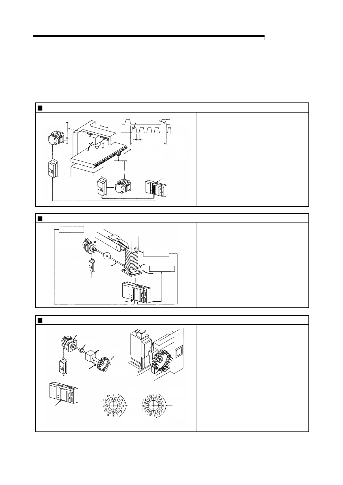
Punch press (X, Y feed positioning)
Y axis
servomotor
Gear and ball screw
Servo
amplifier
Servo amplifier
Press head
Y axis
X axis
Y axis
X axis
servomotor
160mm
320mm
Press punching
12s
X axis
Gear and rack & pinion
QD75
15m/min
(2000r/min)
15m/min
(1875r/min)
MELSEC-Q
To punch insulation material or leather, etc.,
as the same shape at a high yield, positioning
is carried out with the X axis and Y axis
servos.
After positioning the table with the X axis
servo, the press head is positioned with the Y
axis servo, and is then punched with the
press.
When the material type or shape changes, the
press head die is changed, and the positioning
pattern is changed.
X axis
Y axis
Palletizer
Conveyor control
Servomotor
(with brakes)
Servo amplifier
Reduction
gears
Ball screw
(From QD75)
Conveyor
Position detector
Palletizer
Unloader control
QD75
Compact machining center (ATC magazine positioning)
Servomotor
Servo
amplifier
QD75
Coupling
Positioning pin
Reduction
gears
Tool
(12 pcs., 20 pcs.)
ATC tool
magazine
Rotation direction
for calling
11, 12, 1, 2 or 3
Current
value
retrieval
position
Rotation direction
for calling
5, 6, 7, 8, 9 or 10
<No. of tools: 20><No. of tools: 12>
Rotation direction
for calling
17 to 20, 1 to 5
Current
value
retrieval
position
Rotation direction
for calling 7 to 16
Using the servo for one axis, the palletizer is
positioned at a high accuracy.
The amount to lower the palletizer according to
the material thickness is saved.
The ATC tool magazine for a compact
machining center is positioned.
The relation of the magazine's current value
and target value is calculated, and positioning
is carried out with forward run or reverse run to
achieve the shortest access time.
1 - 5
•
•
•
•
•
1 PRODUCT OUTLINE
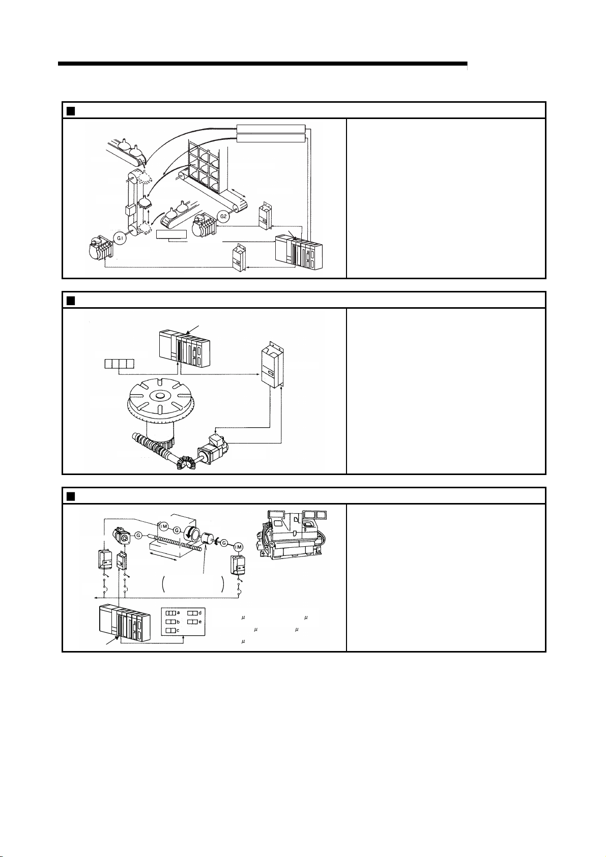
Lifter (Storage of Braun tubes onto aging rack)
B conveyor
Lifter
Counterweight
Reduction
gears
Servomotor
(with brakes)
C conveyor
A conveyor
Loader
Servomotor
Servo amplifier
Aging rack
Index table (High-accuracy indexing of angle)
QD75
Unloader
Loader/unloader
Servo amplifier
QD75
MELSEC-Q
During the aging process of braun tubes,
storage onto the rack is carried out by
positioning with the AC servo.
The up/down positioning of the lifter is carried
out with the 1-axis servo, and the horizontal
position of the aging rack is positioned with the
2-axis servo.
The index table is positioned at a high accuracy
using the 1-axis servo.
Digital switch
Index table
Worm gears
Inner surface grinder
Servomotor
Inverter
220VAC
60Hz
QD75
Servo
amplifier
Motor
Workpiece
Fix the grinding stone,
feed the workpiece,
and grind.
Operation panel
Detector
Servomotor
Grinding stone
Motor
Inverter
a. Total feed
amount ( m)
b. Finishing
feed amount ( m)
c. Compensation
amount ( m)
Servo
amplifier
d. Rough grind ing speed ( m/s)
e. Fine grinding
speed ( m/s)
The grinding of the workpiece's inner surface
is controlled with the servo and inverter.
The rotation of the workpiece is controlled with
the 1-axis inverter, and the rotation of the
grinding stone is controlled with the 2-axis
inverter. The workpiece is fed and ground with
the 3-axis servo.
1 - 6
 Loading...