

SAFETY PRECAUTIONS
(Please read these instructions before using this equipment.)
Before using this product, please read this manual and the relevant manuals introduced in this manual
carefully and pay full attention to safety to handle the product correctly.
Refer to the Users manual of the QCPU module to use for a description of the PLC system safety
precautions.
In this manual, the safety instructions are ranked as "DANGER" and "CAUTION".
Indicates that incorrect handling may cause hazardous
Depending on circumstances, procedures indicated by
results.
In any case, it is important to follow the directions for usage.
Please save this manual to make it accessible when required and always forward it to the end user.
DANGER
CAUTION
conditions, resulting in death or severe injury.
Indicates that incorrect handling may cause hazardous
conditions, resulting in medium or slight personal injury or
physical damage.
CAUTION may also be linked to serious
A - 1
For Safe Operations
1. Prevention of electric shocks
DANGER
Never open the front case or terminal covers while the power is ON or the unit is running, as this
may lead to electric shocks.
Never run the unit with the front case or terminal cover removed. The high voltage terminal and
charged sections will be exposed and may lead to electric shocks.
Never open the front case or terminal cover at times other than wiring work or periodic
inspections even if the power is OFF. The insides of the module and servo amplifier are charged
and may lead to electric shocks.
Completely turn off the externally supplied power used in the system before mounting or removing
the module, performing wiring work, or inspections. Failing to do so may lead to electric shocks.
When performing wiring work or inspections, turn the power OFF, wait at least ten minutes, and
then check the voltage with a tester, etc. Failing to do so may lead to electric shocks.
Be sure to ground the module, servo amplifier and servomotor (Ground resistance : 100 or
less). Do not ground commonly with other devices.
The wiring work and inspections must be done by a qualified technician.
Wire the units after installing the module, servo amplifier and servomotor. Failing to do so may
lead to electric shocks or damage.
Never operate the switches with wet hands, as this may lead to electric shocks.
Do not damage, apply excessive stress, place heavy things on or sandwich the cables, as this
may lead to electric shocks.
Do not touch the module, servo amplifier, servomotor connector or terminal blocks while the
power is ON, as this may lead to electric shocks.
Do not touch the built-in power supply, built-in grounding or signal wires of the module and servo
amplifier, as this may lead to electric shocks.
2. For fire prevention
CAUTION
Install the module, servo amplifier, servomotor and regenerative resistor on incombustible.
Installing them directly or close to combustibles will lead to fire.
If a fault occurs in the module or servo amplifier, shut the power OFF at the servo amplifier's
power source. If a large current continues to flow, fire may occur.
When using a regenerative resistor, shut the power OFF with an error signal. The regenerative
resistor may abnormally overheat due to a fault in the regenerative transistor, etc., and may lead
to fire.
Always take heat measures such as flame proofing for the inside of the control panel where the
servo amplifier or regenerative resistor is installed and for the wires used. Failing to do so may
lead to fire.
Do not damage, apply excessive stress, place heavy things on or sandwich the cables, as this
may lead to fire
.
A - 2
3. For injury prevention
CAUTION
Do not apply a voltage other than that specified in the instruction manual on any terminal.
Doing so may lead to destruction or damage.
Do not mistake the terminal connections, as this may lead to destruction or damage.
Do not mistake the polarity ( + / - ), as this may lead to destruction or damage.
Do not touch the heat radiating fins of module or servo amplifier, regenerative resistor and
servomotor, etc., while the power is ON and for a short time after the power is turned OFF. In this
timing, these parts become very hot and may lead to burns.
Always turn the power OFF before touching the servomotor shaft or coupled machines, as these
parts may lead to injuries.
Do not go near the machine during test operations or during operations such as teaching.
Doing so may lead to injuries.
4. Various precautions
Strictly observe the following precautions. Mistaken handling of the unit may lead to faults,
injuries or electric shocks.
(1) System structure
CAUTION
Always install a leakage breaker on the module and servo amplifier power source.
If installation of an electromagnetic contactor for power shut off during an error, etc., is specified in
the instruction manual for the servo amplifier, etc., always install the electromagnetic contactor.
Install the emergency stop circuit externally so that the operation can be stopped immediately and
the power shut off.
Use the module, servo amplifier, servomotor and regenerative resistor with the correct
combinations listed in the instruction manual. Other combinations may lead to fire or faults.
Use the CPU module, base unit and positioning module with the correct combinations listed in the
instruction manual. Other combinations may lead to faults.
If safety standards (ex., robot safety rules, etc.,) apply to the system using the module, servo
amplifier and servomotor, make sure that the safety standards are satisfied.
Construct a safety circuit externally of the module or servo amplifier if the abnormal operation of
the module or servo amplifier differ from the safety directive operation in the system.
In systems where coasting of the servomotor will be a problem during the forced stop, emergency
stop, servo OFF or power supply OFF, use dynamic brakes.
Make sure that the system considers the coasting amount even when using dynamic brakes.
In systems where perpendicular shaft dropping may be a problem during the forced stop,
emergency stop, servo OFF or power supply OFF, use both dynamic brakes and electromagnetic
brakes.
The dynamic brakes must be used only on errors that cause the forced stop, emergency stop, or
servo OFF. These brakes must not be used for normal braking.
The brakes (electromagnetic brakes) assembled into the servomotor are for holding applications,
and must not be used for normal braking.
A - 3
CAUTION
The system must have a mechanical allowance so that the machine itself can stop even if the
stroke limits switch is passed through at the max. speed.
Use wires and cables that have a wire diameter, heat resistance and bending resistance
compatible with the system.
Use wires and cables within the length of the range described in the instruction manual.
The ratings and characteristics of the parts (other than module, servo amplifier and servomotor)
used in a system must be compatible with the module, servo amplifier and servomotor.
Install a cover on the shaft so that the rotary parts of the servomotor are not touched during
operation.
There may be some cases where holding by the electromagnetic brakes is not possible due to the
life or mechanical structure (when the ball screw and servomotor are connected with a timing belt,
etc.). Install a stopping device to ensure safety on the machine side.
(2) Parameter settings and programming
CAUTION
Set the parameter values to those that are compatible with the module, servo amplifier,
servomotor and regenerative resistor model and the system application. The protective functions
may not function if the settings are incorrect.
The regenerative resistor model and capacity parameters must be set to values that conform to
the operation mode, servo amplifier and servo power supply module. The protective functions
may not function if the settings are incorrect.
Set the mechanical brake output and dynamic brake output validity parameters to values that are
compatible with the system application. The protective functions may not function if the settings
are incorrect.
Set the stroke limit input validity parameter to a value that is compatible with the system
application. The protective functions may not function if the setting is incorrect.
Set the servomotor encoder type (increment, absolute position type, etc.) parameter to a value
that is compatible with the system application. The protective functions may not function if the
setting is incorrect.
Set the servomotor capacity and type (standard, low-inertia, flat, etc.) parameter to values that
are compatible with the system application. The protective functions may not function if the
settings are incorrect.
Set the servo amplifier capacity and type parameters to values that are compatible with the
system application. The protective functions may not function if the settings are incorrect.
Use the program commands for the program with the conditions specified in the instruction
manual.
Set the sequence function program capacity setting, device capacity, latch validity range, I/O
assignment setting, and validity of continuous operation during error detection to values that are
compatible with the system application. The protective functions may not function if the settings
are incorrect.
A - 4
CAUTION
Some devices used in the program have fixed applications, so use these with the conditions
specified in the instruction manual.
The input devices and data registers assigned to the link will hold the data previous to when
communication is terminated by an error, etc. Thus, an error correspondence interlock program
specified in the instruction manual must be used.
Use the interlock program specified in the intelligent function module's instruction manual for the
program corresponding to the intelligent function module.
(3) Transportation and installation
CAUTION
Transport the product with the correct method according to the mass.
Use the servomotor suspension bolts only for the transportation of the servomotor. Do not
transport the servomotor with machine installed on it.
Do not stack products past the limit.
When transporting the module or servo amplifier, never hold the connected wires or cables.
When transporting the servomotor, never hold the cables, shaft or detector.
When transporting the module or servo amplifier, never hold the front case as it may fall off.
When transporting, installing or removing the module or servo amplifier, never hold the edges.
Install the unit according to the instruction manual in a place where the mass can be withstood.
Do not get on or place heavy objects on the product.
Always observe the installation direction.
Keep the designated clearance between the module or servo amplifier and control panel inner
surface or the module and servo amplifier, module or servo amplifier and other devices.
Do not install or operate modules, servo amplifiers or servomotors that are damaged or that have
missing parts.
Do not block the intake/outtake ports of the servo amplifier and servomotor with cooling fan.
Do not allow conductive matter such as screw or cutting chips or combustible matter such as oil
enter the module, servo amplifier or servomotor.
The module, servo amplifier and servomotor are precision machines, so do not drop or apply
strong impacts on them.
Securely fix the module, servo amplifier and servomotor to the machine according to the
instruction manual. If the fixing is insufficient, these may come off during operation.
Always install the servomotor with reduction gears in the designated direction. Failing to do so
may lead to oil leaks.
A - 5
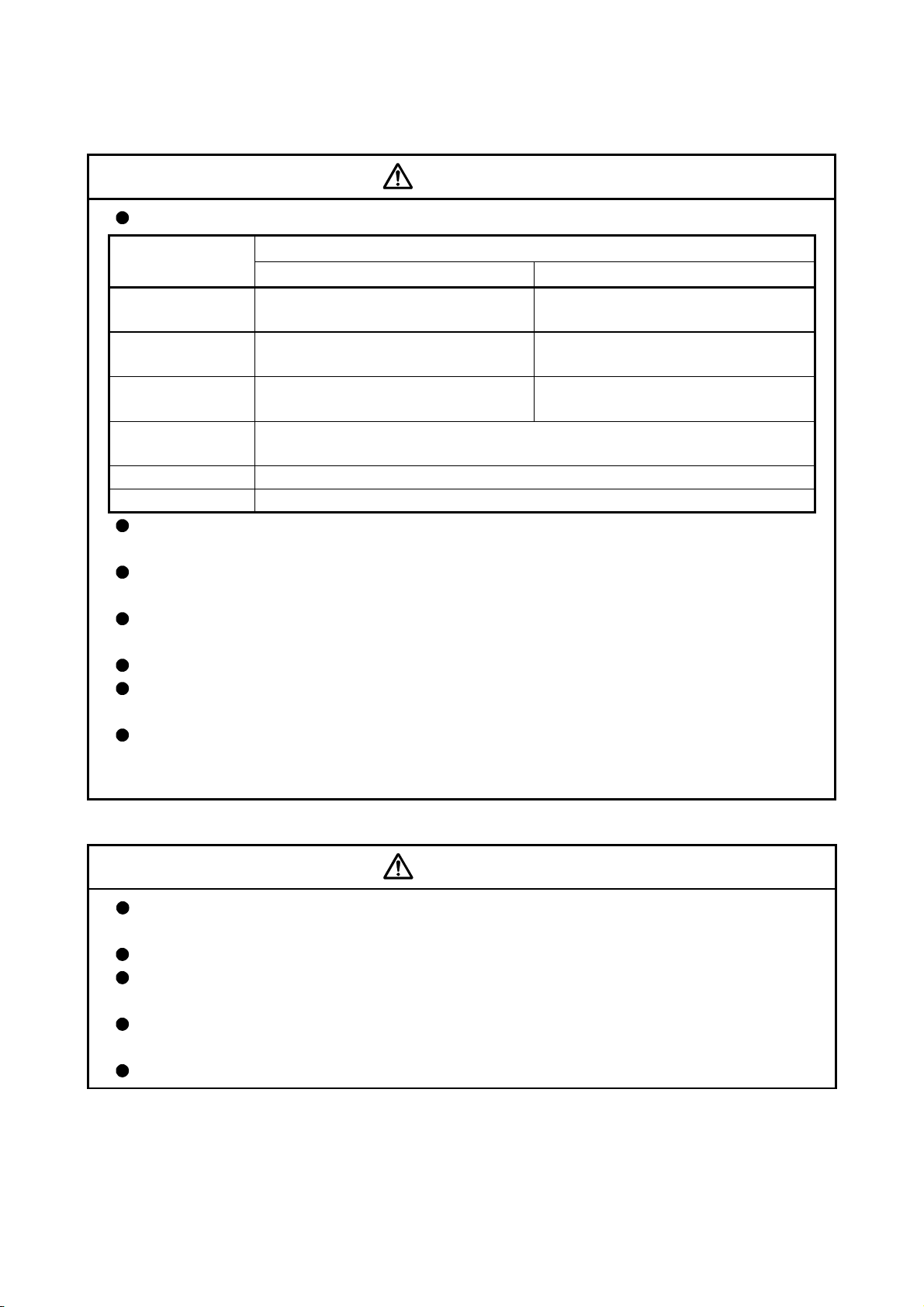
CAUTION
Store and use the unit in the following environmental conditions.
Environment
Ambient
temperature
Ambient humidity
Storage
temperature
Atmosphere
Altitude
Vibration
Module/Servo amplifier Servomotor
According to each instruction manual.
According to each instruction manual.
According to each instruction manual.
Indoors (where not subject to direct sunlight).
No corrosive gases, flammable gases, oil mist or dust must exist
1000m (3280.84ft.) or less above sea level
According to each instruction manual
Conditions
0°C to +40°C (With no freezing)
(32°F to +104°F)
80% RH or less
(With no dew condensation)
-20°C to +65°C
(-4°F to +149°F)
When coupling with the servomotor shaft end, do not apply impact such as by hitting with a
hammer. Doing so may lead to detector damage.
Do not apply a load larger than the tolerable load onto the servomotor shaft. Doing so may lead
to shaft breakage.
When not using the module for a long time, disconnect the power line from the module or servo
amplifier.
Place the module and servo amplifier in static electricity preventing vinyl bags and store.
When storing for a long time, please contact with our sales representative.
Also, execute a trial operation.
Make sure that the connectors for the servo amplifier and peripheral devices have been securely
installed until a click is heard.
Not doing so could lead to a poor connection, resulting in erroneous input and output.
(4) Wiring
CAUTION
Correctly and securely wire the wires. Reconfirm the connections for mistakes and the terminal
screws for tightness after wiring. Failing to do so may lead to run away of the servomotor.
After wiring, install the protective covers such as the terminal covers to the original positions.
Do not install a phase advancing capacitor, surge absorber or radio noise filter (option FR-BIF) on
the output side of the servo amplifier.
Correctly connect the output side (terminal U, V, W). Incorrect connections will lead the
servomotor to operate abnormally.
Do not connect a commercial power supply to the servomotor, as this may lead to trouble.
A - 6
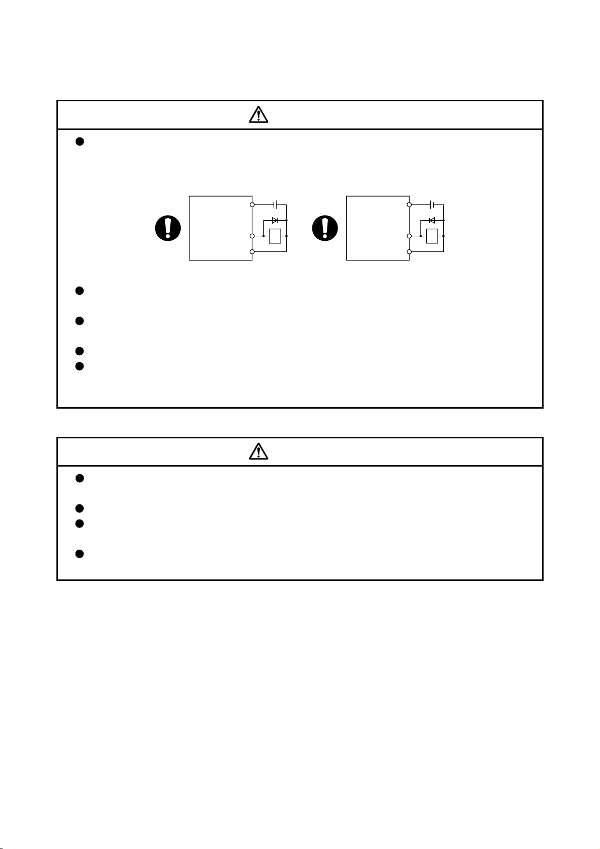
CAUTION
Do not mistake the direction of the surge absorbing diode installed on the DC relay for the control
signal output of brake signals, etc. Incorrect installation may lead to signals not being output
when trouble occurs or the protective functions not functioning.
Servo amplifier
DOCOM
Control output
signal
DICOM
For the sink output interface For the source output interface
24VDC
RA
Servo amplifier
DOCOM
Control output
signal
DICOM
24VDC
RA
Do not connect or disconnect the connection cables between each unit, the encoder cable or
PLC expansion cable while the power is ON.
Securely tighten the cable connector fixing screws and fixing mechanisms. Insufficient fixing may
lead to the cables combing off during operation.
Do not bundle the power line or cables.
Use applicable solderless terminals and tighten them with the specified torque.
If any solderless spade terminal is used, it may be disconnected when the terminal screw comes
loose, resulting in failure.
(5) Trial operation and adjustment
CAUTION
Confirm and adjust the program and each parameter before operation. Unpredictable
movements may occur depending on the machine.
Extreme adjustments and changes may lead to unstable operation, so never make them.
When using the absolute position system function, on starting up, and when the module or
absolute value motor has been replaced, always perform a home position return.
Before starting test operation, set the parameter speed limit value to the slowest value, and make
sure that operation can be stopped immediately if a hazardous state occurs.
A - 7
(6) Usage methods
CAUTION
Immediately turn OFF the power if smoke, abnormal sounds or odors are emitted from the
module, servo amplifier or servomotor.
Always execute a test operation before starting actual operations after the program or parameters
have been changed or after maintenance and inspection.
Do not attempt to disassemble and repair the units excluding a qualified technician whom our
company recognized.
Do not make any modifications to the unit.
Keep the effect or electromagnetic obstacles to a minimum by installing a noise filter or by using
wire shields, etc.
Electromagnetic obstacles may affect the electronic devices used near the module or servo
amplifier.
When using the CE Mark-compliant equipment design, refer to the "EMC Installation Guidelines"
(data number IB(NA)-67339) and refer to the corresponding EMC guideline information for the
servo amplifiers and other equipment.
Note that when the reference axis speed is designated for interpolation operation, the speed of
the partner axis (2nd axis, 3rd axis and 4th axis) may be larger than the set speed (larger than
the speed limit value).
Use the units with the following conditions.
Item Conditions
Input power According to each instruction manual.
Input frequency According to each instruction manual.
Tolerable momentary power failure According to each instruction manual.
A - 8
(7) Corrective actions for errors
CAUTION
If an error occurs in the self diagnosis of the module or servo amplifier, confirm the check details
according to the instruction manual, and restore the operation.
If a dangerous state is predicted in case of a power failure or product failure, use a servomotor
with electromagnetic brakes or install a brake mechanism externally.
Use a double circuit construction so that the electromagnetic brake operation circuit can be
operated by emergency stop signals set externally.
Shut off with the
Shut off with servo ON signal OFF,
alarm, electromagnetic brake signal.
Servomotor
Electromagnetic
brakes
RA1
emergency stop
signal(EMG).
EMG
24VDC
If an error occurs, remove the cause, secure the safety and then resume operation after alarm
release.
The unit may suddenly resume operation after a power failure is restored, so do not go near the
machine. (Design the machine so that personal safety can be ensured even if the machine
restarts suddenly.)
(8) Maintenance, inspection and part replacement
CAUTION
Perform the daily and periodic inspections according to the instruction manual.
Perform maintenance and inspection after backing up the program and parameters for the
module and servo amplifier.
Do not place fingers or hands in the clearance when opening or closing any opening.
Periodically replace consumable parts such as batteries according to the instruction manual.
Do not touch the lead sections such as ICs or the connector contacts.
Before touching the module, always touch grounded metal, etc. to discharge static electricity from
human body. Failure to do so may cause the module to fail or malfunction.
Do not directly touch the module's conductive parts and electronic components.
Touching them could cause an operation failure or give damage to the module.
Do not place the module or servo amplifier on metal that may cause a power leakage or wood,
plastic or vinyl that may cause static electricity buildup.
Do not perform a megger test (insulation resistance measurement) during inspection.
When replacing the module or servo amplifier, always set the new module settings correctly.
When the module or absolute value motor has been replaced, carry out a home position return
operation using one of the following methods, otherwise position displacement could occur.
1) After writing the servo data to the positioning module using programming software, switch on
the power again, then perform a home position return operation.
A - 9
CAUTION
After maintenance and inspections are completed, confirm that the position detection of the
absolute position detector function is correct.
Do not drop or impact the battery installed to the module.
Doing so may damage the battery, causing battery liquid to leak in the battery. Do not use the
dropped or impacted battery, but dispose of it.
Do not short circuit, charge, overheat, incinerate or disassemble the batteries.
The electrolytic capacitor will generate gas during a fault, so do not place your face near the
module or servo amplifier.
The electrolytic capacitor and fan will deteriorate. Periodically replace these to prevent secondary
damage from faults. Replacements can be made by our sales representative.
Lock the control panel and prevent access to those who are not certified to handle or install
electric equipment.
Do not mount/remove the module onto/from the base unit more than 50 times (IEC61131-2-
compliant), after the first use of the product. Failure to do so may cause malfunction.
Do not burn or break a module and servo amplifier. Doing so may cause a toxic gas.
(9) About processing of waste
When you discard module, servo amplifier, a battery (primary battery) and other option articles,
please follow the law of each country (area).
CAUTION
This product is not designed or manufactured to be used in equipment or systems in situations
that can affect or endanger human life.
When considering this product for operation in special applications such as machinery or systems
used in passenger transportation, medical, aerospace, atomic power, electric power, or
submarine repeating applications, please contact your nearest Mitsubishi sales representative.
Although this product was manufactured under conditions of strict quality control, you are strongly
advised to install safety devices to forestall serious accidents when it is used in facilities where a
breakdown in the product is likely to cause a serious accident.
(10) General cautions
CAUTION
All drawings provided in the instruction manual show the state with the covers and safety
partitions removed to explain detailed sections. When operating the product, always return the
covers and partitions to the designated positions, and operate according to the instruction
manual.
A - 10

REVISIONS
The manual number is given on the bottom left of the back cover.
Print Date Manual Number Revision
May., 2005 IB(NA)-0300117-A First edition
Dec., 2011 IB(NA)-0300117-B
[Partial correction]
Safety instructions, Section 4.3.1 Partial change of sentence
Japanese Manual Version IB-0300098
This manual confers no industrial property rights or any rights of any other kind, nor does it confer any patent licenses.
Mitsubishi Electric Corporation cannot be held responsible for any problems involving industrial property rights which
may occur as a result of using the contents noted in this manual.
© 2005 MITSUBISHI ELECTRIC CORPORATION
A - 11

INTRODUCTION
Thank you for purchasing the Mitsubishi general-purpose programmable logic controller MELSEC-Q Series.
Always read through this manual, and fully comprehend the functions and performance of the Q Series PLC
before starting use to ensure correct usage of this product.
CONTENTS
SAFETY INSTRUCTIONS............................................................................................................................A- 1
REVISIONS ...................................................................................................................................................A- 11
INTRODUCTION...........................................................................................................................................A 12
CONTENTS...................................................................................................................................................A- 13
About Manuals ..............................................................................................................................................A- 19
Using This Manual.........................................................................................................................................A- 19
Conformation to the EMC Directive ..............................................................................................................A- 19
Generic Terms and Abbreviations ................................................................................................................A- 20
Component List .............................................................................................................................................A- 20
Section 1 Product Specifications and Handling
1. Product Outline 1- 1 to 1- 28
1.1 Positioning control .................................................................................................................................... 1- 2
1.1.1 Features of QD75MH ........................................................................................................................ 1- 2
1.1.2 Purpose and applications of positioning control............................................................................... 1- 5
1.1.3 Mechanism of positioning control ..................................................................................................... 1- 7
1.1.4 Overview of positioning control functions ......................................................................................... 1- 8
1.1.5 Outline design of positioning system ...............................................................................................1- 18
1.1.6 Communicating signals between QD75MH and each module....................................................... 1- 19
1.2 Flow of system operation ........................................................................................................................ 1- 22
1.2.1 Flow of all processes........................................................................................................................ 1- 22
1.2.2 Outline of starting ............................................................................................................................. 1- 24
1.2.3 Outline of stopping ........................................................................................................................... 1- 26
1.2.4 Outline for restarting ......................................................................................................................... 1- 28
2. System Configuration 2- 1 to 2- 8
2.1 General image of system ......................................................................................................................... 2- 2
2.2 Component list ......................................................................................................................................... 2- 4
2.3 Applicable system .................................................................................................................................... 2- 6
2.4 How to check the function version and SERIAL No. .............................................................................. 2- 8
3. Specifications and Functions 3- 1 to 3- 24
3.1 Performance specifications...................................................................................................................... 3- 2
3.2 List of functions ....................................................................................................................................... 3- 4
3.2.1 QD75MH control functions ................................................................................................................ 3- 4
3.2.2 QD75MH main functions ................................................................................................................... 3- 6
A - 12

3.2.3 QD75MH sub functions and common functions .............................................................................. 3- 8
3.2.4 Combination of QD75MH main functions and sub functions .......................................................... 3- 12
3.3 Specifications of input/output signals with PLC CPU ............................................................................ 3- 14
3.3.1 List of input/output signals with PLC CPU ....................................................................................... 3- 14
3.3.2 Details of input signals (QD75MH
3.3.3 Details of output signals (PLC CPU
3.4 Specifications of interfaces with external devices.................................................................................. 3- 18
3.4.1 Electrical specifications of input signals .......................................................................................... 3- 18
3.4.2 Signal layout for external device connection connector.................................................................. 3- 19
3.4.3 List of input signal details ................................................................................................................. 3- 20
3.4.4 Interface internal circuit .................................................................................................................... 3- 21
3.5 External circuit design ............................................................................................................................. 3- 22
4. Installation, Wiring and Maintenance of the Product 4- 1 to 4- 18
4.1 Outline of installation, wiring and maintenance....................................................................................... 4- 2
4.1.1 Installation, wiring and maintenance procedures ............................................................................. 4- 2
4.1.2 Names of each part ........................................................................................................................... 4- 3
4.1.3 Handling precautions ........................................................................................................................ 4- 5
4.2 Installation ................................................................................................................................................ 4- 7
4.2.1 Precautions for installation................................................................................................................ 4- 7
4.3 Wiring....................................................................................................................................................... 4- 10
4.3.1 Precautions for wiring....................................................................................................................... 4- 10
4.4 Confirming the installation and wiring..................................................................................................... 4- 16
4.4.1 Items to confirm when installation and wiring are completed .........................................................4- 16
4.5 Maintenance............................................................................................................................................ 4- 17
4.5.1 Precautions for maintenance ........................................................................................................... 4- 17
4.5.2 Disposal instructions ........................................................................................................................ 4- 17
PLC CPU)............................................................................. 3- 15
QD75MH) .......................................................................... 3- 17
5. Data Used for Positioning Control (List of buffer memory addresses) 5- 1 to 5-172
5.1 Types of data............................................................................................................................................ 5- 2
5.1.1 Parameters and data required for control......................................................................................... 5- 2
5.1.2 Setting items for positioning parameters .......................................................................................... 5- 6
5.1.3 Setting items for OPR parameters.................................................................................................... 5- 8
5.1.4 Setting items for servo parameters................................................................................................... 5- 9
5.1.5 Setting items for positioning data..................................................................................................... 5- 11
5.1.6 Setting items for block start data ..................................................................................................... 5- 14
5.1.7 Setting items for condition data ....................................................................................................... 5- 15
5.1.8 Types and roles of monitor data ......................................................................................................5- 18
5.1.9 Types and roles of control data ....................................................................................................... 5- 20
5.2 List of parameters ................................................................................................................................... 5- 24
5.2.1 Basic parameters 1 .......................................................................................................................... 5- 24
5.2.2 Basic parameters 2 .......................................................................................................................... 5- 28
5.2.3 Detailed parameters 1...................................................................................................................... 5- 30
5.2.4 Detailed parameters 2...................................................................................................................... 5- 38
5.2.5 OPR basic parameters..................................................................................................................... 5- 50
5.2.6 OPR detailed parameters ................................................................................................................ 5- 56
A - 13

5.2.7 Servo parameters (Basic setting) .................................................................................................... 5- 62
5.2.8 Servo parameters (Gain • filter setting)........................................................................................... 5- 68
5.2.9 Servo parameters (Expansion setting) ............................................................................................ 5- 80
5.2.10 Servo parameters (Input/Output setting) ....................................................................................... 5- 86
5.3 List of positioning data ............................................................................................................................ 5- 90
5.4 List of block start data ............................................................................................................................5-106
5.5 List of condition data ..............................................................................................................................5-112
5.6 List of monitor data................................................................................................................................. 5-118
5.6.1 System monitor data .......................................................................................................................5-118
5.6.2 Axis monitor data............................................................................................................................. 5-128
5.7 List of control data ..................................................................................................................................5-148
5.7.1 System control data ........................................................................................................................ 5-148
5.7.2 Axis control data ..............................................................................................................................5-150
6. Sequence Program Used for Positioning Control 6- 1 to 6- 72
6.1 Precautions for creating program ........................................................................................................... 6- 2
6.2 List of devices used................................................................................................................................. 6- 5
6.3 Creating a program .................................................................................................................................6- 15
6.3.1 General configuration of program .................................................................................................... 6- 15
6.3.2 Positioning control operation program............................................................................................. 6- 16
6.4 Positioning program examples ............................................................................................................... 6- 20
6.5 Program details ....................................................................................................................................... 6- 52
6.5.1 Initialization program ........................................................................................................................6- 52
6.5.2 Start details setting program ............................................................................................................6- 53
6.5.3 Start program.................................................................................................................................... 6- 55
6.5.4 Continuous operation interrupt program.......................................................................................... 6- 64
6.5.5 Restart program ............................................................................................................................... 6- 66
6.5.6 Stop program.................................................................................................................................... 6- 69
7. Memory Configuration and Data Process 7- 1 to 7- 20
7.1 Configuration and roles of QD75MH memory......................................................................................... 7- 2
7.1.1 Configuration and roles of QD75MH memory..................................................................................7- 2
7.1.2 Buffer memory area configuration .................................................................................................... 7- 5
7.2 Data transmission process ...................................................................................................................... 7- 8
A - 14

Section 2 Control Details and Setting
8. OPR Control 8- 1 to 8- 16
8.1 Outline of OPR control ............................................................................................................................. 8- 2
8.1.1 Two types of OPR control ................................................................................................................. 8- 2
8.2 Machine OPR........................................................................................................................................... 8- 5
8.2.1 Outline of the machine OPR operation............................................................................................. 8- 5
8.2.2 Machine OPR method....................................................................................................................... 8- 6
8.2.3 OPR method (1): Near-point dog method ........................................................................................ 8- 7
8.2.4 OPR method (2): Count method 1) .................................................................................................. 8- 9
8.2.5 OPR method (3): Count method 2) ................................................................................................. 8- 11
8.2.6 OPR method (4): Data set method .................................................................................................. 8- 13
8.3 Fast OPR ................................................................................................................................................. 8- 14
8.3.1 Outline of the fast OPR operation.................................................................................................... 8- 14
8.4 Selection of OPR set condition .............................................................................................................. 8- 16
8.4.1 Outline of the selection of OPR set condition.................................................................................. 8- 16
9. Major Positioning Control 9- 1 to 9-116
9.1 Outline of major positioning controls ....................................................................................................... 9- 2
9.1.1 Data required for major positioning control ...................................................................................... 9- 4
9.1.2 Operation patterns of major positioning controls ............................................................................. 9- 5
9.1.3 Designating the positioning address................................................................................................ 9- 15
9.1.4 Confirming the current value............................................................................................................ 9- 16
9.1.5 Control unit "degree" handling ......................................................................................................... 9- 18
9.1.6 Interpolation control.......................................................................................................................... 9- 21
9.2 Setting the positioning data ................................................................................................................... 9- 25
9.2.1 Relation between each control and positioning data ...................................................................... 9- 25
9.2.2 1-axis linear control .......................................................................................................................... 9- 27
9.2.3 2-axis linear interpolation control ..................................................................................................... 9- 29
9.2.4 3-axis linear interpolation control ..................................................................................................... 9- 33
9.2.5 4-axis linear interpolation control ..................................................................................................... 9 -39
9.2.6 1-axis fixed-feed control ................................................................................................................... 9- 44
9.2.7 2-axis fixed-feed control (interpolation) ........................................................................................... 9- 46
9.2.8 3-axis fixed-feed control (interpolation) ........................................................................................... 9- 48
9.2.9 4-axis fixed-feed control (interpolation) .......................................................................................... 9- 52
9.2.10 2-axis circular interpolation control with sub point designation .................................................... 9- 54
9.2.11 2-axis circular interpolation control with center point designation ................................................ 9- 60
9.2.12 1-axis speed control ....................................................................................................................... 9- 68
9.2.13 2-axis speed control ....................................................................................................................... 9- 71
9.2.14 3-axis speed control ....................................................................................................................... 9- 74
9.2.15 4-axis speed control ....................................................................................................................... 9- 78
9.2.16 Speed-position switching control (INC mode)............................................................................... 9- 83
9.2.17 Speed-position switching control (ABS mode).............................................................................. 9- 91
9.2.18 Position-speed switching control ................................................................................................... 9- 99
9.2.19 Current value changing ................................................................................................................9- 106
A - 15

9.2.20 NOP instruction ............................................................................................................................ 9- 111
9.2.21 JUMP instruction .......................................................................................................................... 9- 112
9.2.22 LOOP............................................................................................................................................ 9- 114
9.2.23 LEND ............................................................................................................................................ 9- 115
10. High-Level Positioning Control 10- 1 to 10- 26
10.1 Outline of high-level positioning control .............................................................................................. 10- 2
10.1.1 Data required for high-level positioning control ............................................................................ 10- 3
10.1.2 "Block start data" and "condition data" configuration ................................................................... 10- 4
10.2 High-level positioning control execution procedure ............................................................................ 10- 6
10.3 Setting the block start data ..................................................................................................................10- 7
10.3.1 Relation between various controls and block start data ..............................................................10- 7
10.3.2 Block start (normal start) .............................................................................................................. 10- 8
10.3.3 Condition start ..............................................................................................................................10- 10
10.3.4 Wait start....................................................................................................................................... 10- 11
10.3.5 Simultaneous start ...................................................................................................................... 10- 12
10.3.6 Repeated start (FOR loop) ......................................................................................................... 10- 13
10.3.7 Repeated start (FOR condition) .................................................................................................. 10- 14
10.3.8 Restrictions when using the NEXT start ...................................................................................... 10- 15
10.4 Setting the condition data ...................................................................................................................10- 16
10.4.1 Relation between various controls and the condition data ......................................................... 10- 16
10.4.2 Condition data setting examples ................................................................................................. 10- 19
10.5 Multiple axes simultaneous start control ............................................................................................ 10- 20
10.6 Start program for high-level positioning control .................................................................................10- 23
10.6.1 Starting high-level positioning control.......................................................................................... 10- 23
10.6.2 Example of a start program for high-level positioning control .................................................... 10- 24
11. Manual Control 11- 1 to 11- 36
11.1 Outline of manual control .................................................................................................................... 11- 2
11.1.1 Three manual control methods ..................................................................................................... 11- 2
11.2 JOG operation...................................................................................................................................... 11- 4
11.2.1 Outline of JOG operation .............................................................................................................. 11- 4
11.2.2 JOG operation execution procedure ............................................................................................ 11- 7
11.2.3 Setting the required parameters for JOG operation..................................................................... 11- 8
11.2.4 Creating start programs for JOG operation................................................................................. 11- 10
11.2.5 JOG operation example ............................................................................................................... 11- 13
11.3 Inching operation................................................................................................................................. 11- 17
11.3.1 Outline of inching operation ......................................................................................................... 11- 17
11.3.2 Inching operation execution procedure ....................................................................................... 11- 20
11.3.3 Setting the required parameters for inching operation ............................................................... 11- 21
11.3.4 Creating a program to enable/disable the inching operation ...................................................... 11- 22
11.3.5 Inching operation example........................................................................................................... 11- 25
11.4 Manual pulse generator operation...................................................................................................... 11- 27
11.4.1 Outline of manual pulse generator operation ..............................................................................11- 27
11.4.2 Manual pulse generator operation execution procedure ............................................................11- 31
11.4.3 Setting the required parameters for manual pulse generator operation .................................... 11- 32
11.4.4 Creating a program to enable/disable the manual pulse generator operation........................... 11- 33
A - 16

12. Control Sub Functions 12- 1 to 12-106
12.1 Outline of sub functions ....................................................................................................................... 12- 2
12.1.1 Outline of sub functions ................................................................................................................ 12- 2
12.2 Sub functions specifically for machine OPR .......................................................................................12- 4
12.2.1 OPR retry function......................................................................................................................... 12- 4
12.2.2 OP shift function ........................................................................................................................... 12- 8
12.3 Functions for compensating the control ............................................................................................. 12- 11
12.3.1 Backlash compensation function ................................................................................................. 12- 11
12.3.2 Electronic gear function ............................................................................................................... 12- 13
12.3.3 Near pass function .......................................................................................................................12- 20
12.4 Functions to limit the control ............................................................................................................... 12- 23
12.4.1 Speed limit function ...................................................................................................................... 12- 23
12.4.2 Torque limit function .....................................................................................................................12- 25
12.4.3 Software stroke limit function ....................................................................................................... 12- 29
12.4.4 Hardware stroke limit function ..................................................................................................... 12- 35
12.4.5 Forced stop function..................................................................................................................... 12- 39
12.5 Functions to change the control details.............................................................................................. 12- 42
12.5.1 Speed change function ................................................................................................................ 12- 42
12.5.2 Override function .......................................................................................................................... 12- 49
12.5.3 Acceleration/deceleration time change function ......................................................................... 12- 52
12.5.4 Torque change function ............................................................................................................... 12- 56
12.6 Absolute position system ....................................................................................................................12- 59
12.7 Other functions .................................................................................................................................... 12- 61
12.7.1 Step function................................................................................................................................. 12- 61
12.7.2 Skip function ................................................................................................................................. 12- 66
12.7.3 M code output function................................................................................................................. 12- 69
12.7.4 Teaching function .........................................................................................................................12- 73
12.7.5 Target position change function .................................................................................................. 12- 79
12.7.6 Command in-position function .....................................................................................................12- 83
12.7.7 Acceleration/deceleration processing function............................................................................ 12- 86
12.7.8 Pre-reading start function............................................................................................................. 12- 89
12.7.9 Deceleration start flag function ................................................................................................... 12- 94
12.7.10 Stop command processing for deceleration stop function ..................................................... 12- 98
12.7.11 Speed control 10 x multiplier setting for degree axis function .............................................12- 101
12.7.12 Operation setting for incompletion of OPR function .............................................................12- 103
12.8 Servo ON/OFF ..................................................................................................................................12- 105
12.8.1 Servo ON/OFF ........................................................................................................................... 12- 105
12.8.2 Follow up function ......................................................................................................................12- 106
13. Common Functions 13- 1 to 13- 8
13.1 Outline of common functions ............................................................................................................... 13- 2
13.2 Parameter initialization function........................................................................................................... 13- 3
13.3 Execution data backup function .......................................................................................................... 13- 5
13.4 External signal selection function ........................................................................................................ 13- 7
13.5 External I/O signal logic switching function ......................................................................................... 13- 8
A - 17

14. Dedicated Instructions 14- 1 to 14- 18
14.1 List of dedicated instructions ............................................................................................................... 14- 2
14.2 Interlock during dedicated instruction is executed .............................................................................. 14- 2
14.3 PSTRT1, PSTRT2, PSTRT3, PSTRT4............................................................................................... 14- 3
14.4 TEACH1, TEACH2, TEACH 3, TEACH 4 ........................................................................................... 14- 7
14.5 PFWRT................................................................................................................................................ 14- 11
14.6 PINIT.................................................................................................................................................... 14- 15
15. Troubleshooting 15- 1 to 15- 60
15.1 Error and warning details ..................................................................................................................... 15- 2
15.2 List of errors ......................................................................................................................................... 15- 6
15.2.1 QD75MH detection error ............................................................................................................... 15- 6
15.2.2 MR-J3-B detection error............................................................................................................... 15- 36
15.3 List of warnings ................................................................................................................................... 15- 50
15.3.1 QD75MH detection warning......................................................................................................... 15- 50
15.3.2 MR-J3-B detection warning .........................................................................................................15- 56
15.4 LED display functions ......................................................................................................................... 15- 60
Appendices Appendix- 1 to Appendix-72
Appendix 1 Functions........................................................................................................................Appendix- 3
Appendix 1.1 Multiple CPU correspond function..........................................................................Appendix- 3
Appendix 1.2 The combination of software package for QD75MH and QCPU ..........................Appendix- 3
Appendix 2 Positioning data (No.1 to 600) List of buffer memory addresses.................................Appendix- 4
Appendix 3 Connection with servo amplifiers .................................................................................Appendix- 28
Appendix 3.1 Connection of SSCNET
Appendix 3.2 Wiring of SSCNET
Appendix 4 Connection with external device connector .................................................................Appendix- 34
Appendix 4.1 Connector...............................................................................................................Appendix- 34
Appendix 4.2 Wiring of manual pulse generator cable ...............................................................Appendix- 36
Appendix 5 Comparisons with conventional positioning modules..................................................Appendix- 37
Appendix 5.1 Comparisons with QD75P model ..........................................................................Appendix- 37
Appendix 5.2 Comparisons with QD75M1/ QD75M2/ QD75M4 models ...................................Appendix- 38
Appendix 6 Positioning control troubleshooting ..............................................................................Appendix- 51
Appendix 7 List of buffer memory addresses..................................................................................Appendix- 57
Appendix 8 External dimension drawing .........................................................................................Appendix- 71
INDEX Index- 1 to Index - 10
INDEX..................................................................................................................................................... Index - 1
cables .........................................................................Appendix- 28
cables.................................................................................. Appendix- 30
A - 18

About Manuals
The following manuals are also related to this product.
In necessary, order them by quoting the details in the tables below.
Related Manuals
Manual Name
GX Configurator-QP Operating Manual
Describes how to use GX Configurator-QP for the following and other purposes: creating data
(parameters, positioning data, etc.), sending the data to the module, monitoring the positioning
operations, and testing.
(The manual is supplied with the software.)
Using This Manual
The symbols used in this manual are shown below.
Pr.
Da.
....... Symbol indicating positioning parameter and OPR parameter item.
....... Symbol indicating positioning data, block start data and condition
data item.
Md.
Cd.
....... Symbol indicating monitor data item.
....... Symbol indicating control data item.
(A serial No. is inserted in the
mark.)
Conformation to the EMC Directive
The CE logo is printed on the rating plate on the main body of the PLC that
conforms to the EMC directive instruction.
To make this product conform to the EMC directive instruction, please refer to
section 4.3.1 "Precautions for wiring" of the chapter 4 "Installation, Wiring and
Maintenance of the Product" and the EMC Installation Guidelines (IB(NA)67339).
Representation of numerical values used in this manual.
Buffer memory addresses, error codes and warning codes are represented in
decimal.
X/Y devices are represented in hexadecimal.
Setting data and monitor data are represented in decimal or hexadecimal. Data
ended by "H" or "h" are represented in hexadecimal.
(Example) 10.........Decimal
10H ......Hexadecimal
Manual Number
(Model Code)
SH-080172
(13JU19)
A - 19

Generic Terms and Abbreviations
Unless specially noted, the following generic terms and abbreviations are used in this
manual.
Generic term/abbreviation Details of generic term/abbreviation
PLC CPU Generic term for PLC CPU on which QD75MH can be mounted.
QD75MH
MR-J3-B Servo amplifier: Abbreviation for MR-J3-B. ( = capacity)
Peripheral device
GX Developer Abbreviation for GX Developer (SW4D5C-GPPW-E or later).
GX Configurator-QP Abbreviation for GX Configurator-QP (SW2D5C-QD75P-E (Version 2.21X) or later).
Servo amplifier (drive unit) Abbreviation for SSCNET compatible servo amplifier (drive unit).
Manual pulse generator Abbreviation for manual pulse generator (MR-HDP01) (prepared by user).
DOS/V personal computer IBM PC/AT® and compatible DOS/V compliant personal computer.
Personal computer Generic term for DOS/V personal computer.
Workpiece Generic term for moving body such as workpiece and tool, and for various control targets.
Axis 1, axis 2, axis 3,
axis 4
1-axis, 2-axis, 3-axis,
4-axis
OPR Generic term for "Home position return".
OP Generic term for "Home position".
SSCNET
(Note)
Generic term for positioning module QD75MH1, QD75MH2 and QD75MH4.
The module type is described to indicate a specific module.
Generic term for DOS/V personal computer that can run the following "GX Developer" and
"GX Configurator-QP".
Indicates each axis connected to QD75MH.
Indicates the number of axes. (Example: 2-axis = Indicates two axes such as axis 1 and axis 2,
axis 2 and axis 3, and axis 3 and axis 1.)
High speed synchronous communication network between QD75MH and servo amplifier.
(Note): SSCNET: Servo System Controller NETwork
Component List
The table below shows the component included in respective positioning modules:
Module name
QD75MH1 QD75MH2 QD75MH4
QD75MH1 positioning module 1
QD75MH2 positioning module 1
QD75MH4 positioning module 1
Before Using the Product 1
Quantity
A - 20

Section 1
Section 1 Product Specifications and Handling
Section 1 is configured for the following purposes (1) to (5).
(1) To understand the outline of positioning control, and the QD75MH specifications
and functions
(2) To carry out actual work such as installation and wiring
(3) To set parameters and data required for positioning control
(4) To create a PLC program required for positioning control
(5) To understand the memory configuration and data transmission process
When diverting any of the program examples introduced in this manual to the actual
system, fully verify that there are no problems in the controllability of the target system.
Read "Section 2" for details on each control.
Chapter 1 Product outline .............................................................................................. 1- 1 to 1- 28
Chapter 2 System configuration .................................................................................... 2- 1 to 2- 8
Chapter 3 Specifications and Functions........................................................................ 3- 1 to 3- 24
Chapter 4 Installation, Wiring and Maintenance of the Product ................................... 4- 1 to 4- 16
Chapter 5 Data Used for Positioning Control................................................................ 5- 1 to 5-172
Chapter 6 PLC Program Used for Positioning Control ................................................. 6- 1 to 6- 72
Chapter 7 Memory Configuration and Data Process .................................................... 7- 1 to 7- 20

MEMO

1
Chapter 1 Product Outline
The purpose and outline of positioning control using QD75MH are explained in this chapter.
Reading this chapter will help you understand what can be done using the positioning
system and which procedure to use for a specific purpose.
By understanding "What can be done", and "Which procedure to use" beforehand, the
positioning system can be structured smoothly.
1.1 Positioning control ........................................................................................................1- 2
1.1.1 Features of QD75MH .....................................................................................1- 2
1.1.2 Purpose and applications of positioning control ............................................1- 5
1.1.3 Mechanism of positioning control...................................................................1- 7
1.1.4 Overview of positioning control functions.......................................................1- 8
1.1.5 Outline design of positioning system.............................................................1- 18
1.1.6 Communicating signals between QD75MH and each module ....................1- 19
1.2 Flow of system operation ............................................................................................1- 22
1.2.1 Flow of all processes .....................................................................................1- 22
1.2.2 Outline of starting...........................................................................................1- 24
1.2.3 Outline of stopping.........................................................................................1- 26
1.2.4 Outline for restarting ......................................................................................1- 28
1 - 1

1 PRODUCT OUTLINE
1.1 Positioning control
1.1.1 Features of QD75MH
The features of the QD75MH are shown below.
(1) Availability of one, two, and four axis modules
(a) One, two and four axis positioning modules are available.
(b) For connecting any of the QD75MH modules to the base unit, a single slot
(2) Wide variety of positioning control functions
(a) A wide variety of positioning control functions essential to any positioning
(b) For each positioning data, the user can specify any of the following control
MELSEC-Q
They can be selected according to the PLC CPU type and the number of
required control axes. (Refer to Section 2.2.)
and 32 dedicated I/O channels are required.
Within the limit imposed by the maximum number of inputs and outputs
supported by the PLC CPU, up to 64 modules can be used. (Refer to
Section 2.3.)
system are supported: positioning to an arbitrary position, fixed-feed
control, equal-speed control, and so on. (Refer to Section 5.3 and 9.2.)
1) Up to 600 positioning data items, including such information as
positioning addresses, control systems, and operation patterns, can be
prepared for each axis.
Using the prepared positioning data, the positioning control is
performed independently for each axis. (In addition, such controls as
interpolation involving two to four axes and simultaneous startup of
multiple axes are possible.)
2) Independent control of each axis can be achieved in linear control
mode (executable simultaneously over four axes).
Such control can either be the independent positioning control using a
single positioning data or the continuous positioning control enabled by
the continuous processing of multiple positioning data.
3) Coordinated control over multiple axes can take the form of either the
linear interpolation through the speed or position control of two to four
axes or the circular interpolation involving two axes.
Such control can either be the independent positioning control using a
single positioning data or the continuous positioning control enabled by
the continuous processing of multiple positioning data.
systems: position control, speed control, speed-position switching control,
position-speed switching control, and so on. (Refer to Section 5.3 and 9.2.)
1 - 2

1 PRODUCT OUTLINE
(3) Quick startup (Refer to Section 3.1.)
(4) SSCNET makes the connection to the servo amplifier possible
(5) Easy application to the absolute position system
MELSEC-Q
(c) Continuous positioning control using multiple positioning data can be
executed in accordance with the operation patterns the user assigned to
the positioning data. (Refer to Section 5.3 and 9.1.2.)
Continuous positioning control can be executed over multiple blocks, where
each block consists of multiple positioning data. (Refer to Section 10.3.2.)
(d) OPR control is given additional features (Refer to Section 8.2.)
Four different machine OPR methods are provided: the near point dog
method, two count methods, and the data set method.
(e) Two acceleration/deceleration control methods are provided: automatic
trapezoidal acceleration/deceleration and S-pattern acceleration/
deceleration. (Refer to Section 12.7.7.)
A positioning operation starts up quickly taking as little as 3.5 ms to 4 ms.
When operation using simultaneous start function or interpolation operation is
executed, the axes start without delay.
(Example) Axis 1 and Axis 3 are started by the : No delay in Axis 1 and
simultaneous start function Axis 3 start
Axis 2 and Axis 4 are started by the : No delay in Axis 2 and
interpolation operation Axis 4 start
(a) The QD75MH can be directly connected to the servo amplifier using the
MELSERVO (Mitsubishi's servo amplifier: MR-J3-B).
(b) Because the SSCNET
servo amplifier, or servo amplifiers, saving wiring can be realized. The
cable between the QD75MH and servo amplifier or servo amplifiers can be
extended up to 50m (164.04ft.).
(c) By the use of SSCNET
electromagnetic noise and others from servo amplifier, etc. are reduced.
(d) The servo parameters can be set on the QD75MH side to write or read
them to/from the servo amplifier using the SSCNET
(e) The actual current value and error description contained in the servo can
be checked by the buffer memory of the QD75MH.
(a) The absolute position-corresponding servo amplifier is connected to have
an application to the absolute position system.
(b) Once the OP have been established, the OPR operation can also be made
unnecessary when the power is supplied.
(c) With the absolute position system, the data set method OPR is used to
establish the OP.
(d) When the setting unit is "degree", the absolute position system with
unlimited length feed can be configured.
1 - 3
cable is used to connect the QD75MH and the
cable (Optical communication), influence of
.

1 PRODUCT OUTLINE
(6) Control can be realized with the mechanical system input
(7) Easy maintenance
(8) Support of intelligent function module dedicated instructions
(9) Setups, monitoring, and testing through GX Configurator-QP
(10) Addition of forced stop function
MELSEC-Q
The external inputs, such as external start, stop, and speed/position switching is
used to perform the positioning control without using the PLC program.
Each QD75MH positioning module incorporates the following improvements in
maintainability:
(a) Data such as the positioning data and parameters can be stored on a flash
ROM inside the QD75MH, eliminating the need of a battery for retaining
data. (Refer to Section 7.1.1.)
(b) Error messages are classified in more detail to facilitate the initial
troubleshooting procedure. (Refer to Section 15.1.)
(c) The module retains 16 error messages and 16 warning messages recently
output, offering more complete error and warning histories.
(Refer to Section 5.6.1.)
Dedicated instructions such as the positioning start instruction, and teaching
instruction are provided.
The use of such dedicated instruction simplifies PLC programs.(Refer to Chapter
14.)
Using GX Configurator-QP, the user can control the QD75MH parameters and
positioning data without having to be conscious of the buffer memory addresses.
Moreover, GX Configurator-QP has a test function which allows the user to check
the wiring before creating a PLC program for positioning control, or test operation
the QD75MH using created parameters and positioning data for checking their
integrity.
The control monitor function of GX Configurator-QP allows the user to debug
programs efficiently.
As forced stop input signal to the connector for external equipment connection is
added, batch forced stop is available for all axes of servo amplifier.
(Refer to Section 12.4.5.)
Selection for whether using "Forced stop input signal" or not can be made with
parameter.
1 - 4
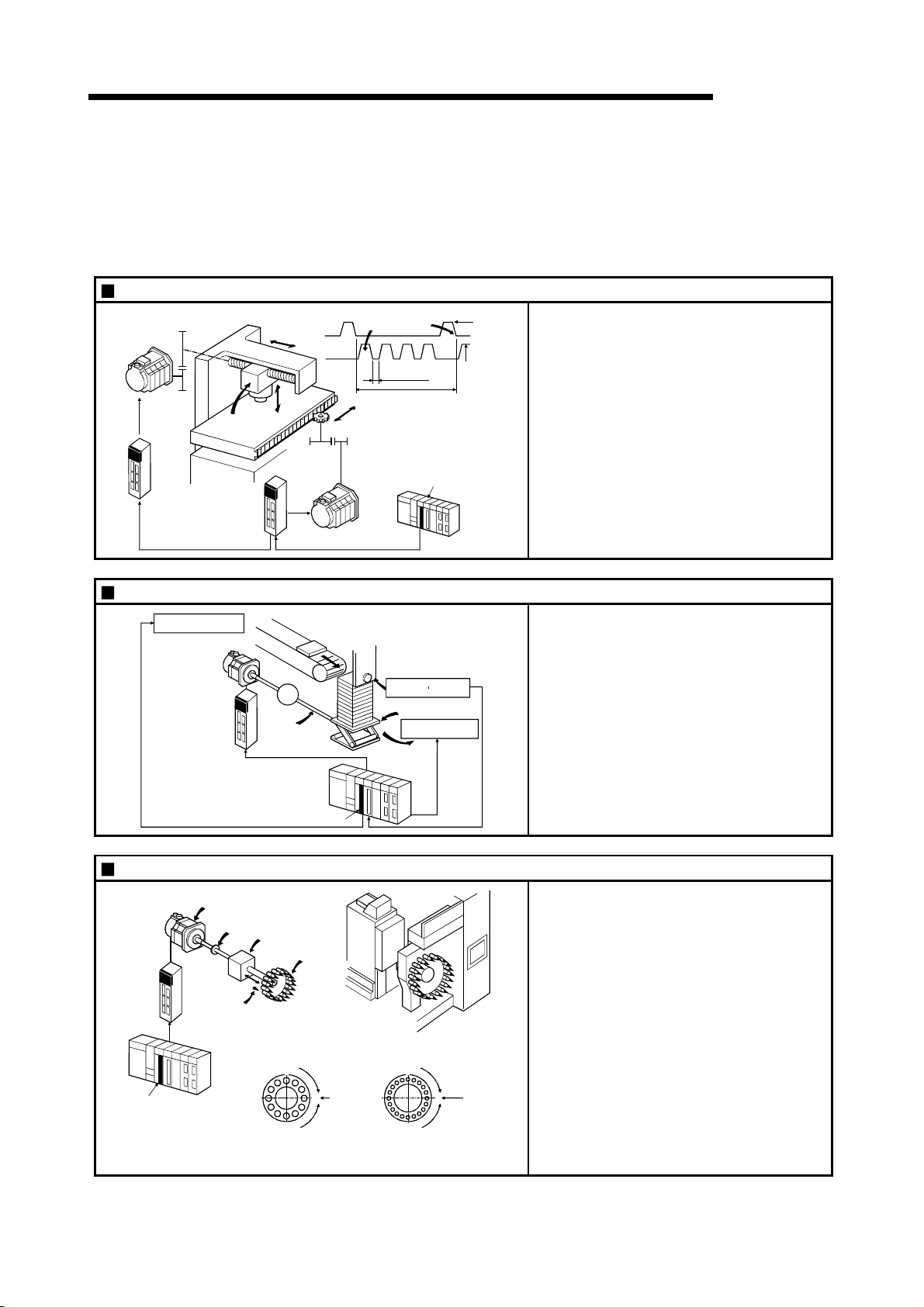
1 PRODUCT OUTLINE
1.1.2 Purpose and applications of positioning control
"Positioning" refers to moving a moving body, such as a workpiece or tool (hereinafter,
generically called "workpiece") at a designated speed, and accurately stopping it at the
target position. The main application examples are shown below.
Punch press (X, Y feed positioning
Gear and ball screw
Y axis
servomotor
Servo
amplifier
Y axis
Palletizer
Press head
Servo
amplifier
Conveyor control
Servomotor
(with brakes)
Servo
amplifier
Y axis
X axis
servomotor
Conveyor
G
Reduction
gears
Ball screw
(From QD75MH)
)
X axis
Y axis
X axis
Gear and rack & pinion
160mm
320mm
Press
punching
12s
PLC
MELSEC-Q
X axis
Position detector
Palletizer
Unloader control
QD75MH
15m/min
(2000r/min)
15m/min
(1875r/min)
MELSEC-Q
•
To punch insulation material or leather, etc.,
as the same shape at a high yield, positioning
is carried out with the X axis and Y axis
servos.
•
After positioning the table with the X axis
servo, the press head is positioned with the Y
axis servo, and is then punched with the
press.
•
When the material type or shape changes, the
press head die is changed, and the positioning
pattern is changed.
•
Using the servo for one axis, the palletizer is
positioned at a high accuracy.
•
The amount to lower the palletizer according to
the material thickness is saved.
PLC
MELSEC-Q
QD75MH
Compact machining center (ATC magazine positioning)
Servo
amplifier
QD75MH
Servomotor
Coupling
Positioning
pin
PLC
MELSEC-Q
Reduction
gears
ATC tool
magazine
Tool
(12 pcs., 20 pcs.)
Rotation direction
for calling
11, 12, 1, 2 or 3
1
2
12
11
95
<No. of tools: 12> <No. of tools: 20>
3
Current
value
410
retrieval
position
6
8
7
Rotation direction
for calling 5, 6, 7, 8, 9 or 10
1
220
19
18
17
16
15
14
13
10
12
11
Rotation direction
for calling
17 to 20, 1 to 5
3
4
Current
5
value
6
retrieval
7
8
position
9
Rotation direction
for calling 7 to 16
1 - 5
•
The ATC tool magazine for a compact
machining center is positioned.
•
The relation of the magazine's current value
and target value is calculated, and positioning
is carried out with forward run or reverse run to
achieve the shortest access time.
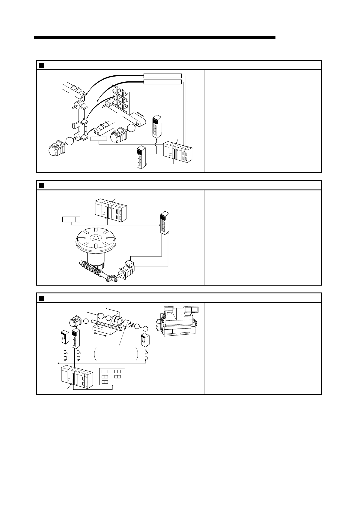
r
1 PRODUCT OUTLINE
Lifter (Storage of Braun tubes onto aging rack)
B conveyor
Lifter
Counterweight
Reduction
gears
Servomotor
(with brakes)
G1
A conveyor
Loader
C conveyor
G2
Servomotor
Servo
amplifier
Aging rack
Unloader
Loader/unloader
Servo
amplifier
QD75MH
MELSEC-Q
•
During the aging process of Braun tubes,
storage onto the rack is carried out by
positioning with the AC servo.
•
The up/down positioning of the lifter is carried
out with the 1-axis servo, and the horizontal
position of the aging rack is positioned with the
2-axis servo.
Index table (High-accuracy indexing of angle)
Index table
PLC
MELSEC-Q
Digital switch
Worm gears
QD75MH
Inner surface grinder
PLC
MELSEC-Q
Inverter
220VAC
60Hz
QD75MH
Servomotor
Servo
amplifier
Motor
IM
G
Fix the grinding
stone, feed the
workpiece, and grind.
Operation panel
Workpiece
a
b
c
Grinding stone
a. Total feed
d
amount (µm)
b. Finishing
e
feed amount (µm)
c. Compensation
amount (µm)
G
Detector
Servomotor
Motor
G
IM
PLC MELSEC-Q
Inverter
d. Rough grind ing speed (µm/s)
e. Fine grinding
speed (µm/s)
Servo
amplifie
•
The index table is positioned at a high accuracy
using the 1-axis servo.
•
The grinding of the workpiece's inner surface
is controlled with the servo and inverter.
•
The rotation of the workpiece is controlled with
the 1-axis inverter, and the rotation of the
grinding stone is controlled with the 2-axis
inverter. The workpiece is fed and ground with
the 3-axis servo.
1 - 6
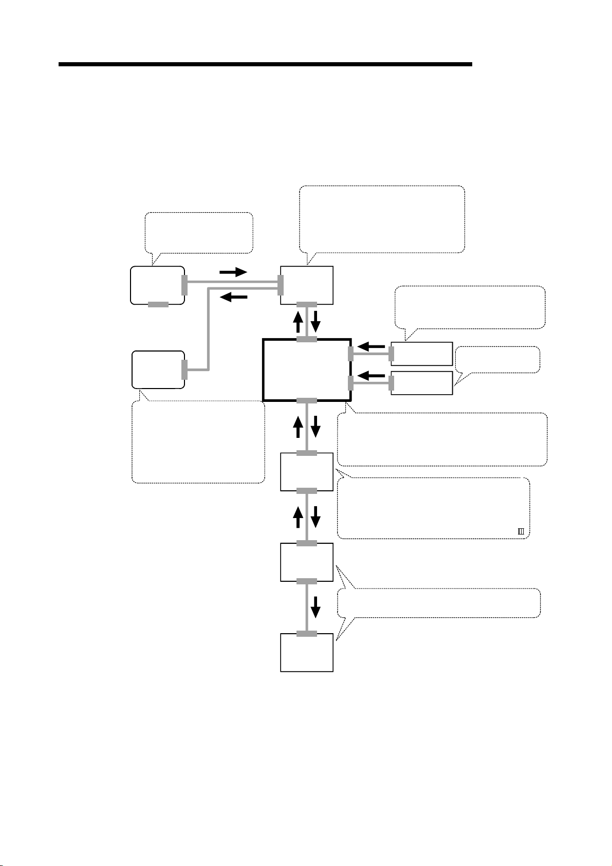
1 PRODUCT OUTLINE
1.1.3 Mechanism of positioning control
In the positioning system using the QD75MH, various software and devices are used
for the following roles. The QD75MH realizes complicated positioning control when it
reads in various signals, parameters and data and is controlled with the PLC CPU.
MELSEC-Q
Creates control order and
conditions as a sequence
program.
GX Developer
GX
Configurator
-QP
Sets the parameters and
positioning data for control.
Outputs the start command for
JOG operation, etc., during test
operation with the test mode.
Monitors the positioning operation.
Stores the created program.
The QD75MH outputs the start signal and
QD75MH positioning
module
stop signal following the stored program.
QD75MH errors, etc., are detected.
PLC CPU
Servo
amplifier
Outputs signals such as the start
signal, forced stop input signal, stop
signal, limit signal and control
changeover signal to the QD75MH.
External signal
Stores the parameter and data.
Outputs datas to the servo according to the
instructions from the PLC CPU, GX Configurator-QP,
external signals and manual pulse generator.
Manual pulse
generator
Issues commands by
transmitting pulses.
Receives positioning commands and control
commands from QD75MH, and drives the motor.
Outputs the positioning data of the motor
data and etc., and external input signal of the
servo amplifier to the QD75MH by the SSCNET .
Motor
Carries out the actual work according to commands
from the servo.
Workpiece
(Note): For QD75MH1, 2 and 4, use SW2D5C-QD75P (Version 2.21X) or later of the GX Configurator.
1 - 7

1 PRODUCT OUTLINE
1.1.4 Overview of positioning control functions
The outline of the "overview of positioning control" and "overview of individual
positioning control and continuous positioning control", "overview of block positioning
control" and "overview of acceleration/deceleration processing control" is shown below.
Positioning control
An overview of positioning using positioning data described below.
(1) Linear control
(a) 1-axis linear control
This performs positioning from the start point address (location the axis is
presently stopped) defined on the specified axis to the specified position.
[Control using the absolute system]
1) This performs positioning from the start point address to the specified
position.
2) The start point address and the specified address determine the
movement direction.
[Example]
The following figure shows the operations when the start point address
is 5000 and the positioning address are 2000 and 8000:
2000 5000 8000
MELSEC-Q
Positioning when the specified
address is 2000
Positioning when the specified
address is 8000
Start point address
[Control using the increment system]
1) This performs positioning from the specified increment of travel from the
start point address.
2) The sign of the travel increment determines the direction of travel.
• For positive travel increment…….Positioning in the positive direction
(direction of address increase)
• For negative travel increment…...Positioning in the negative direction
(direction of address decrease)
[Example]
The following figure shows the operations when the start point address
is 5000 and the travel increments are 3000 and -3000:
2000 5000 8000
Movement direction for a negative
movement amount.
Movement direction for a positive
movement amount.
Positioning when the specified
address is -3000.
Positioning when the specified
address is 3000.
Start point address
1 - 8

t
1 PRODUCT OUTLINE
MELSEC-Q
(b) 2-axis linear interpolation control
(Note)
This controls interpolation along a linear locus from the start point address
(current stop position) defined by two axes.
[Control using the absolute system]
1) This performs linear interpolation using two axes from the start point
address to the endpoint address.
2) The start point address and the specified address determine the
direction of travel.
[Example]
The operation when the start point address is 800 for axis 1 and 2000
for axis 2 and the positioning address specified to 2000 for axis 1 and
8000 for axis 2, is shown below.
Axis 1
2000
Start point address
(2000, 800)
800
0
2000
Specified address
(8000, 2000)
Positioning operation
8000
Axis 2
[Control using the increment system]
1) This performs positioning from the specified increment of travel from the
start point address.
2) The sign of the travel increment determines the direction of travel.
• For positive travel increment…….Positioning in the positive direction
(direction of address increase)
• For negative travel increment…….Positioning in the negative direction
(direction of address decrease)
[Example]
The operation when the start point address is 800 for axis 1 and 2000
for axis 2 and the positioning address specified to 1200 for axis 1 and
2000
6000 for axis 2, is shown below.
Axis 1
Start point address
(2000, 800)
End position when the travel incremen
is 1200 for axis 1 and 6000 for axis 2.
800
0
2000
Positioning operation
8000
Axis 2
REMARK
(Note): The interpolation speed during linear interpolation control can be selected
from "synthesized axis" and "reference-axis speed" using the detailed
parameter 1. (Refer to the Section 5.2.3 information about setting "
Interpolation speed designation method" of the detailed parameter 1.)
1 - 9
Pr.20

1 PRODUCT OUTLINE
MELSEC-Q
(2) Circular interpolation control
(Note)
There are two types of circular interpolation controls: circular interpolation with a
specified sub point and circular interpolation with the specified center point.
(a) Circular interpolation with a specified sub point
Circular interpolation is performed using the specified endpoint address and
sub point (passing point) address.
Two methods are available: absolute system and increment system.
Forward
direction
Reverse
direction
Sub point
Start point
address
Reverse
direction
End point
Center point
(Calculated by the QD75)
Forward
direction
(b) Circular interpolation with the specified center point
Circular interpolation is performed using the specified endpoint address and
center point address.
Two methods are available: absolute system and increment system.
Also, the direction of movement can be selected from clockwise or
counterclockwise.
Forward
direction
End point
Reverse
direction
Stop position
Reverse
direction
Center point
Forward
direction
REMARK
(Note): The interpolation speed during circular interpolation control may only be set
to "synthesized speed" for the interpolation speed of the detailed parameter
1. (Refer to the Section 5.2.3 information about setting "
speed designation method" of the detailed parameter 1.)
1 - 10
Pr.20
Interpolation
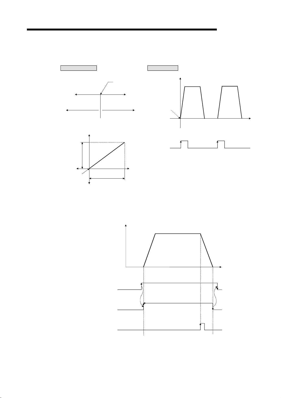
t
1 PRODUCT OUTLINE
(3) Fixed-feed control
Positioning direction
[1-axis fixed-feed control]
This performs positioning for the specified increment of travel.
Operation timing
V
Stop position
Forward directionReverse direction
MELSEC-Q
Movement direction for
a negative movement amount
[2-axis fixed-feed control]
Forward
direction
Travel along
axis 1
Reverse
direction
Stop position
Reverse
direction
Movement direction for
a positive movement amount
Travel along axis 2
Positioning
direction
Forward
direction
Start
command
Start
ON
OFF
(4) Speed control
After command is executed, control continues with the command speed until the
stop command is input.
V
t
ON
Positioning start
signal
BUSY signal
Axis stop signal
OFF
ON
OFF
ON
OFF
(By the PLC
program creation)
1 - 11
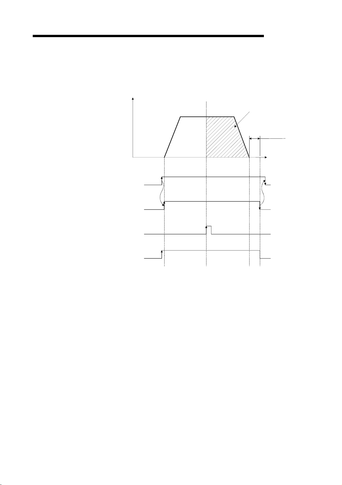
1 PRODUCT OUTLINE
(5) Speed-position switching control
MELSEC-Q
This starts positioning under speed control, and switches to position control
according to the input of the QD75MH speed-position switching signal and
perform positioning for the specified increment of travel.
V
Specified travel
increment
Dwell time
t
(By the PLC
program creation)
Positioning start signal
BUSY signal
Speed-position switching
signal (external signal)
Speed-position switching
enable flag
Speed control Position control
ON
OFF
ON
OFF
ON
OFF
ON
OFF
1 - 12

1 PRODUCT OUTLINE
Individual positioning control and continuous positioning control
The QD75 performs positioning according to the user-set positioning data, which is a
set of information comprised of the control method (position control, speed control,
speed-position switching control), positioning address, operation pattern, and so on.
Up to 600 of positioning data are assigned respectively to positioning data Nos. 1 to
600 per axis and registered to the QD75MH.
The operation pattern set in each positioning data by the user determines whether to
perform positioning operation with one positioning data item or to perform continuous
positioning operation with multiple positioning data items.
(1) Independent positioning control (operation pattern = 00: positioning
MELSEC-Q
complete)
The operation completed upon completion of positioning for the specified
positioning data. The positioning completion of this operation pattern is also used
as the operation pattern for the last positioning data of continuous positioning and
continuous-locus positioning.
V
Positioning complete (00)
Dwell time
t
ON
Positioning start signal
Positioning start
complete signal
BUSY signal
Positioning complete
signal
OFF
ON
OFF
ON
OFF
ON
OFF
(By the PLC
program creation)
1 - 13

1 PRODUCT OUTLINE
(2) Continuous positioning control (operation pattern = 01: positioning
Address(+)
direction
Address(-)
direction
Positininig start signal
Positioning start
complete signal
BUSY signal
Positioning complete
signal
MELSEC-Q
continues)
The operation stops temporarily upon the completion of positioning for the
specified positioning data, and then continues with the next positioning data
number.
This is specified when performing positioning in which the direction changes
because of multiple positioning data items having consecutive positioning data
numbers.
V
Positioning continues (01)
V
OFF
OFF
OFF
OFF
Positioning continues (01)
Positioning
complete
(00)
ON
ON
ON
ON
Dwell time
t
(By the PLC
program creation)
1 - 14

1 PRODUCT OUTLINE
(3) Continuous path control (operation pattern = 11: positioning
Address(+)
direction
Address(-)
direction
Positininig start signal
Positioning start
complete signal
BUSY signal
Positioning complete
signal
MELSEC-Q
continue)
After executing positioning using the specified positioning data, the operation
changes its speed to that of the next positioning data number and continues
positioning.
This is specified when continuously executing multiple positioning data items
having consecutive positioning data numbers at a specified speed.
V
Positioning continue (11)
V
ON
OFF
ON
OFF
ON
OFF
OFF
Positioning continue (11)
ON
Positioning
complete
(00)
Dwell time
t
(By the PLC
program creation)
1 - 15

g
1 PRODUCT OUTLINE
Block positioning control
Block positioning is a control that continuously executes the positioning of specified
blocks. One block equivalent to a series of positioning data up to the completion of
positioning (operation pattern = 00) by Independent or continuous positioning control.
A maximum of 50 blocks per axis can be specified.
Using a one-time start command from the QCPU or external, complex positioning
control can be performed.
The block positioning control can be performed by specifying the positioning start
Address(+)
direction
Address(-)
direction
number and positioning start information in the buffer memory.
V
Positioning complete (00)
V
One block
Positioning continues (01)
Positioning
continue (11)
One block One block
Positioning
complete (00)
Dwell time
Positioning
continue (11)
MELSEC-Q
Positioning
complete (00)
t
Positininig start signal
Start complete signal
BUSY signal
Positioning complete
nal
si
ON
OFF
ON
OFF
ON
OFF
ON
OFF
1 - 16
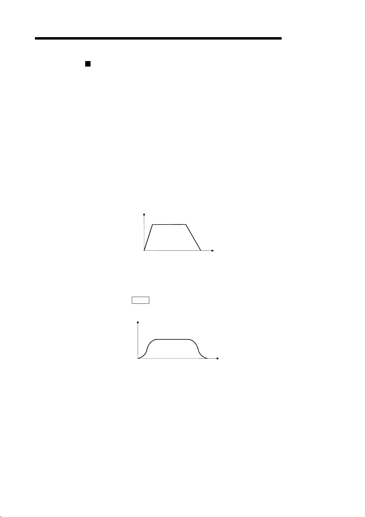
e
V
1 PRODUCT OUTLINE
Overview of acceleration/deceleration processing control
Acceleration/deceleration processing for the positioning processing, manual pulse-
generator processing, OPR processing and JOG processing is performed using the
user-specified method, acceleration time and deceleration time.
(1) Acceleration/deceleration method
MELSEC-Q
There are two types of acceleration and deceleration processing: the automatic
trapezoidal acceleration/deceleration processing method and S-pattern
acceleration/deceleration processing method. A detailed parameter is used to set
which method is used. The specified acceleration/deceleration method is applied
to all accelerations and decelerations when starting and completing positioning
processing, OPR processing and JOG processing, as well as when changing the
speed.
(a) Automatic trapezoidal acceleration/deceleration processing method
This is a method in which linear acceleration/deceleration is carried out
based on the acceleration time, deceleration time, and speed limit value set
by the user.
Velocity
Tim
(b) S-pattern acceleration/deceleration processing method
This method reduces the load on the motor when starting and stopping.
This is a method in which acceleration/deceleration is carried out gradually,
based on the acceleration time, deceleration time, speed limit value, and
Pr.35
"
S-pattern proportion" (1 to 100%) set by the user.
elocity
Time
(2) Acceleration time, deceleration time, sudden-stop deceleration time
(a) For types each of the acceleration time and deceleration time for positioning
control can be set using basic parameters 2 and detailed parameters 2.
• Acceleration time…….The time elapses before the speed of 0 reaches
the limit value.
• Deceleration time…….The time elapses before the speed at the limit
value reaches 0.
(b) The sudden-stop deceleration time (1 to 8388608 ms) is set using the
acceleration time/deceleration time setting size selection of detailed
parameters 2.
1 - 17
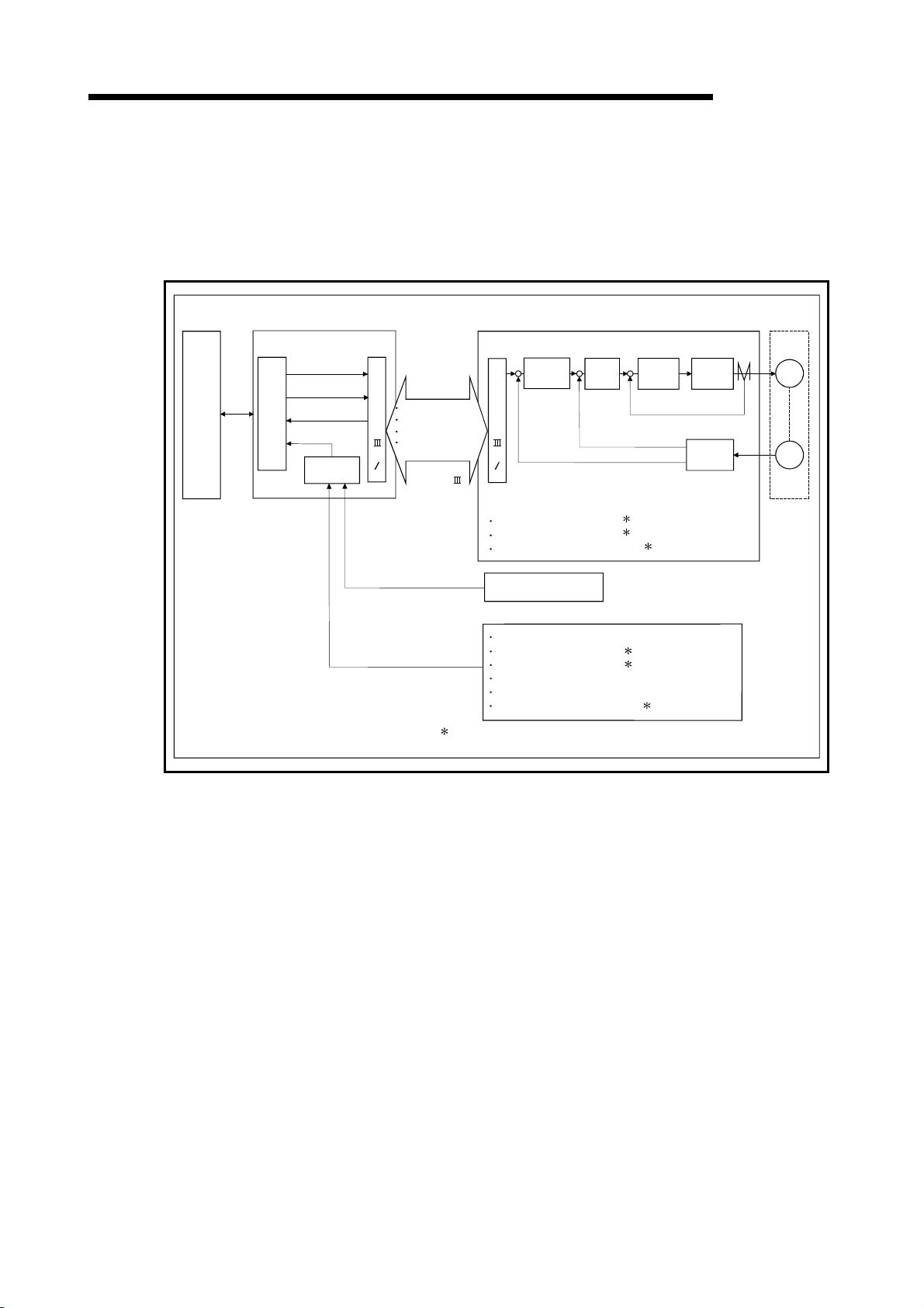
1 PRODUCT OUTLINE
1.1.5 Outline design of positioning system
The outline of the positioning system operation and design, using the QD75MH, is
shown below.
(1) Positioning system using QD75MH
MELSEC-Q
PLC
CPU
Read,
write
and
etc.
QD75MH
Positioning command
Control command
OS
Monitor data
Interface
S
S
C
N
Positioning command
Control command
E
Monitor data
T
External input signal
of servo amplifier
I
F
SSCNET
MR-J3-B
Positioning
control
+
-
Position feedback
+
S
S
-
C
N
E
T
I
F
External input signal of servo amplifier (Refer to MR-J3-B
Instruction manual)
FLS (Upper limit signal)
RLS (Lower limit signal)
DOG (Near-point dog signal)
Manual puse generator
A-phese/B-phese
External input signal (Refer to Section 3.4.2)
EMI (Forced stop input signal)
FLS (Upper limit signal)
RLS (Lower limit signal)
CHG (External command signal/switching signal)
STOP (Stop signal)
DOG (Near-point dog signal)
:Either the QD75MH or servo amplifier can be designated as the
external input signal .(Refer to Section 5.2.3 Detailed parameters 1)
+
Speed
control
-
Speed feedback
+
Current
control
Current feedback
Inverter
-
Interface
Servo
motor
M
PLG
Fig. 1.2 Outline of the operation of positioning system using QD75MH
1 - 18

1 PRODUCT OUTLINE
1.1.6 Communicating signals between QD75MH and each module
The outline of the signal communication between the QD75MH (positioning module)
and PLC CPU, peripheral device and servo amplifier, etc., is shown below.
(A peripheral device communicates with the QD75MH via the PLC CPU to which it is
PLC CPU
Y8,YA,YC,YE
Y9,YB,YD,YF
Y14,Y15,Y16,Y17
Y10,Y11,Y12,Y13
X14,X15,X16,X17
Y0
X0
Y1
X1
Forward run JOG start signal
Reverse run JOG start signal
connected)
PLC READY signal
QD75 READY signal
All axis servo ON signal
Syncronization flag
Execution prohibition flag
Positioning start signal
Positioning complete signal
QD75MH
External
interface
Manual puse generator A-phase
Manual puse generator B-phase
MELSEC-Q
SSCNET
Operating information of
the servo amplifer
Positioning command
Control command
Servo parameter
External input signal of
the servo amplifier
Servo
amplifer
Manual pulse
generator
XC,XD,XE,XF
X10,X11,X12,X13
Y4,Y5,Y6,Y7
X4,X5,X6,X7
X8,X9,XA,XB
Peripherral
device
interface
BUSY signal
Start complete signal
Axis stop signal
M code ON signal
Error detection signal
Data write/read
Parameter write/read
Positioning data write/read
Block start data write/read
Home position return operation
(Test)
JOG operation, inching operation
(Test)
Positioning operation(Test)
Operation monitor
Interface
with
PLC CPU
Forced stop input signal
Upper/lower limit signal
External command signal/
switching signal
Stop signal
Near-point dog signal
External
signal
Peripheral
device
1 - 19

1 PRODUCT OUTLINE
QD75MH PLC CPU
Communication
Control signal
Data (read/write)
Refer to Section 3.3 "Specifications of input/output signals with PLC CPU" for details.
The QD75MH and PLC CPU communicate the following data via the base unit.
Direction
QD75MH Peripheral device
The QD75MH and peripheral device communicate the following data via the PLC
Communication
Data (read/write)
Test operation –
Operation monitor • Monitor data –
CPU:
Direction
QD75MH Servo amplifier
The QD75MH and servo amplifier communicate the following data via the
Communication
SSCNET
SSCNET
Direction
QD75MH
Signal indicating QD75MH state
• QD75 READY signal
• BUSY signal
and etc.
• Parameter
• Positioning data
• Block start data
• Control data
• Monitor data
QD75MH
• Parameter
• Positioning data
PLC CPU PLC CPU QD75MH
Peripheral device Peripheral device QD75MH
.
QD75MH
• Positioning commands
• Control commands
• Servo parameter
Servo amplifier Servo amplifier QD75MH
MELSEC-Q
Signal related to commands
• PLC READY signal
• Various start signals
• Stop signals
• All axis servo ON signal
and etc.
• Parameter
• Positioning data
• Block start data
• Control data
• Parameter
• Positioning data
• OPR control start command
• Positioning control start command
• JOG/Inching operation start command
• Teaching start command
• Manual pulse generator operation
enable/disable command
• Operating information of the servo
amplifier
• Servo parameter
• External input signal of the servo amplifier
1 - 20
1 PRODUCT OUTLINE
QD75MH Manual pulse generator
The QD75MH and manual pulse generator communicate the following data via the
external device connection connector.
(The manual pulse generator should be connected to an external device connection
Communication
Pulse signal –
connector for axis 1 or for axes 1 and 2.)
Direction
QD75MH External signal
The QD75MH and external signal communicate the following data via the external
Communication
Control signal –
device connection connector.
Direction
QD75MH
QD75MH
MELSEC-Q
Manual pulse generator Manual pulse generator QD75MH
• Manual pulse generator A-phase
• Manual pulse generator B-phase
External signal External signal QD75MH
•
Forced stop input signal
•
Upper/lower limit signal
•
External command signal/switching
signal
•
Stop signal
•
Near-point dog signal
1 - 21

1 PRODUCT OUTLINE
1.2 Flow of system operation
1.2.1 Flow of all processes
The positioning control processes, using the QD75MH, are shown below.
MELSEC-Q
Design
Preparation
GX Configurator-QP
1)
Understand the functions and performance, and determine the positioning operation method
(system design)
3)
Setting of the:
· Parameters
· Positioning data
· Block start data
· Condition data
· Servo parameter
Writing of setting data
QD75MH
2)
Installation, wiring
Servo, etc.
5) 6)
PLC CPU
4)
Creation of PLC
program for operation
Refer to (Note)
GX Developer
Writing of program
7) 8)
Monitoring with
test operation,
and debugging
of setting data
Operation
Maintenance
Monitor
9)
10)
11)
Connection confirmation
Test operation
Actual operation
Maintenance
Disposal
Monitoring and
debugging of
operation
program
Monitor
(Note)
When not using
GX Configurator
-QP, carry out
setting, monitoring
and debugging of
the data in 3) with
GX Developer.
1 - 22

1 PRODUCT OUTLINE
MELSEC-Q
Details Reference
Understand the product functions and usage methods, the configuration devices
1)
and specifications required for positioning control, and design the system.
The following work is carried out with the processes shown on the previous page.
•
Chapter 1
•
Chapter 2
•
Chapter 3
•
Chapter 8 to Chapter 13
Install the QD75MH onto the base unit, wire the QD75MH and external connection
2)
devices (drive unit, etc.).
Using GX Configurator-QP, set the parameter, servo parameters, positioning data,
3)
block start data and condition data required for the positioning control to be
executed.
Using GX Developer, create the PLC program required for positioning operation.
4)
(When not using GX Configurator-QP, also create the PLC program for setting
data.)
Write the parameters and positioning data, etc., created with GX Configurator-QP
5)
into the QD75MH.
Using GX Developer, write the created PLC program into the PLC CPU. (When not
6)
using GX Configurator-QP, also write in the PLC program for setting data.)
Carry out test operation and adjustments in the test mode to check the connection
with the QD75MH and external connection device, and to confirm that the
7)
designated positioning operation is executed correctly. (Debug the set "parameters"
and "positioning data", etc.)
Carry out test operation and adjustment to confirm that the designated positioning
8)
operation is executed correctly. (Debug the created PLC program. When not using
GX Configurator-QP, also debug the set data.
•
Chapter 4
•
Chapter 5
•
Chapter 8 to Chapter 13
•
GX Configurator-QP
Operating Manual
•
Chapter 6
•
GX Developer Operating
Manual
•
Chapter 7
•
GX Configurator-QP
Operating Manual
•
Chapter 7
•
GX Developer Operating
Manual
•
GX Configurator-QP
Operating Manual
•
Chapter 13
•
GX Developer Operating
Manual
•
GX Developer Operating
Manual
Actually operate the positioning operation. At this time, monitor the operation state
9)
as required. If an error or warning occurs, remedy.
10) Service the QD75MH as required.
11) Dispose of the QD75MH.
1 - 23
•
Chapter 5
•
Chapter 15
•
GX Configurator-QP
Operating Manual
•
GX Developer Operating
Manual
•
Chapter 4
•
Chapter 4

1 PRODUCT OUTLINE
1.2.2 Outline of starting
The outline for starting each control is shown with the following flowchart.
It is assumed that each module is installed, and the required system configuration,
etc., has been prepared.
Flow of starting
MELSEC-Q
Preparation
Control
functions
Positioning
parameters
OPR
parameters
Servo
parameters
PLC READY
All axis
servo ON
Positioning
data
Block start
data
Installation and connection of module
Setting of hardware
Major positioning control
Position control
Speed control
Speed-position
switching control
Position-speed
switching control
Other control
Set the positioning data.
( Da.1 to Da.10 )
High-level positioning
control
Block start (Normal start)
Condition start
Wait start
Simultaneous start
Repeated start
Set the positioning parameters. ( Pr.1 to Pr.42 , Pr.80 to Pr.84 )
Set the servo parameters. ( Pr.100 to Pr.204 )
Turn the PLC READY signal ON(Y0 ON)
Turn the All axis servo ON signal(Y1 ON)
Set the block start
data.
( Da.11 to Da.19 )
Machine OPR control
Set the OPR parameters.
( Pr.43 to Pr.57 )
OPR control Manual control
JOG operation
Fast OPR control
Inching operation
Manual pulse generator operation
Control data
Start signal
Control start
Control end
Input the start signal.
Method (1) Turn ON the QD75MH start signal from the
PLC CPU
Method (2) Issue the PSTRT instruction from the PLC CPU.
Method (3) Turn the QD75MH external start signal ON
Set the positioning start No. ( Cd.3 )
Set the positioning
starting point No.
( Cd.4 )
1 - 24
Operation
Stop
Set the JOG speed
( Cd.17 )
Set the inching
movement
amount to 0.
( Cd.16 )
Turn the QD75MH JOG
start signal ON from the
PLC CPU
Set the inching
movement
amount to 0.
( Cd.16 )
Set the manual pulse
generator enable flag
to "1".
( Cd.21 )
Set the manual pulse
generator 1 pulse input
magnification.
( Cd.20 )
Operate the
manual pulse
generator

1 PRODUCT OUTLINE
Setting method
: Indicates the PLC program that must be created.
MELSEC-Q
<GX Configurator-QP>
Set with GX Configurator-QP
Set the parameter and data for executing main function,
and the sub functions that need to be set beforehand.
<GX Developer>
Create PLC program
for setting data
When set with "GX Configurator-QP",
this does not need to be created.
<GX Developer>
Create PLC program for
executing main function
Create PLC program for
outputting control signals, such
as start signal, to QD75MH.
Write
Write
PLC
CPU
QD75MH
Write
<GX Developer>
· Speed change
· Current value changing
· Torque limit
· Restart, etc.
Operation PLC program
Create a PLC
program for the
sub functions.
1 - 25
Write
PLC
CPU

1 PRODUCT OUTLINE
1.2.3 Outline of stopping
MELSEC-Q
Stop cause
Forced stop
Fatal stop
(Stop group 1)
Emergency
stop
(Stop group 2)
Relatively safe
stop
(Stop group 3)
Each control is stopped in the following cases.
(1) When each control is completed normally.
(2) When the Servo READY signal is turned OFF.
(3) When a PLC CPU error occurs.
(4) When the PLC READY signal is turned OFF.
(5) When an error occurs in the QD75MH.
(6) When control is intentionally stopped (Stop signal from PLC CPU turned ON, stop
The outline for the stopping process in these cases is shown below. (Excluding (1) for
normal stopping.)
"Forced stop
input signal
from external
device" OFF
Servo
READY OFF
• Servo amplifier
power supply
OFF
• Servo alarm
• Forced stop
input to servo
amplifier
Hardware
stroke limit
upper/lower
limit error
occurrence
Error occurs
in PLC CPU
PLC READY
signal OFF
Error in test
mode
Axis error
detection
(Error other
than stop
group 1 or 2)
"Stop signal"
from
peripheral
device
signal from an external device, etc.).
Axis
Stop
axis
All
axes
Each
axis
Each
axis
All
axes
Each
axis
M code
ON signal
after stop
No
change
No
change
No
change
No
change
Turns
OFF
No
change
No
change
operation
status
after
stopping
Md.26
(
Servo
OFF
Servo
amplifier
disconnected
During
error
Servo
OFF
During
error
During
error
During
error
OPR control Manual control
Machine
OPR
control
)
Servo OFF or free run
(The operation stops with dynamic brake or
electromagnetic brake.)
Deceleration stop/sudden stop
(Select with "
sudden stop selection" )
Deceleration stop/sudden stop
(Select with "
sudden stop selection" )
Deceleration stop/sudden stop
(Select with "
sudden stop selection" )
Fast
OPR
control
Stop process
Major
positioning
control
Pr.37
Pr.38
High-level
positioning
control
Sudden stop group1
Sudden stop group2
JOG/
Inching
operation
Pr.39 Sudden stop group3
Manual
pulse
generator
operation
Deceleration
stop
Deceleration
stop
Deceleration
stop
1 - 26

1 PRODUCT OUTLINE
Stop cause
Intentional stop
(Stop group 3)
"Stop signal"
ON from
external
device
"Axis stop
signal" ON
from PLC
CPU
Stop
axis
Each
axis
Reference
Provide the emergency stop circuits external to the servo system to prevent cases
where danger may result from abnormal operation of the overall in the event of a
power supply fault or servo system failure.
M code
ON signal
after stop
No
change
Axis
operation
status
after
stopping
Md.26
(
When
stopped
(While
waiting)
MELSEC-Q
Stop process
OPR control Manual control
Machine
OPR
)
control
control
Deceleration stop/sudden stop
(Select with "
sudden stop selection" )
Fast
OPR
Major
positioning
control
Pr.39 Sudden stop group3
High-level
positioning
control
JOG/
Inching
operation
Manual
pulse
generator
operation
Deceleration
stop
1 - 27

4
4
1 PRODUCT OUTLINE
1.2.4 Outline for restarting
When a stop cause has occurred during operation with position control causing the
axis to stop, positioning to the end point of the positioning data can be restarted from
the stopped position by using the "
If issued during a continuous positioning or continuous path control operation, the
restart command will cause the positioning to be re-executed using the current position
(pointed by the positioning data No. associated with the moment when the movement
was interrupted) as the start point.
When "
(1) If the "
(2) When "
[Example for incremental system]
Axis 1
MELSEC-Q
Cd.6
Restart command".
Cd.6
Restart command" is ON
Md.26
Axis operation status" is stopped, positioning to the end point of
the positioning data will be restarted from the stopped position regardless of
the absolute system or incremental system.
Md.26
Axis operation status" is not stopped, the warning "Restart not
possible" (warning code: 104) will be applied, and the restart command will be
ignored.
(a) The restart operation when the axis 1 movement amount is 300, and the
axis 2 movement amount is 600 is shown below.
Axis 1
Stop position due to stop cause
00
Start point
address
200
100
100 300 700
Designated end
point position
Axis 2
Restart
Stop position due to stop cause
400
200
100
100 300 700
Stop position
after restart
Operation during
restart
Axis 2
Reference
If the positioning start signal [Y10 to Y13]/external command signal
while the "
Md.26
Axis operation status" is waiting or stopped, positioning will be
restarted from the start of the positioning start data regardless of the absolute
system or incremental system. (
: When the external command signal is set to
"External positioning start")
(Same as normal positioning.)
[Example for incremental system]
(a) The positioning start operation when the axis 1 movement amount is 300
Axis 1
Stop position due to stop cause
00
Start point
address
200
100
100 300 700
and the axis 2 movement amount is 600 is shown below.
Axis 1
Stop position due to stop cause
500
Axis 2
Positioning
start
200
100
100 300 900
Designated end
point position
1 - 28
is turned ON
Stop position
after restart
Operation during
positioning start
Axis 2

Chapter 2 System Configuration
2
In this chapter, the general image of the system configuration of the positioning control
using QD75MH, the configuration devices, applicable CPU and the precautions of
configuring the system are explained.
Prepare the required configuration devices to match the positioning control system.
2.1 General image of system .............................................................................................2- 2
2.2 Component list..............................................................................................................2- 4
2.3 Applicable system.........................................................................................................2- 6
2.4 How to check the function version and SERIAL No. ..................................................2- 8
2 - 1

2 SYSTEM CONFIGURATION
2.1 General image of system
The general image of the system, including the QD75MH, PLC CPU and peripheral
devices is shown below.
(The Nos. in the illustration refer to the "No." in Section 2.2 "Component list".
MELSEC-Q
Extension
cable
CPU
module 1
Main base unit 2
Positioning
module
1
I/O
module
Extension
system
USB cable
5
RS-232 cable
4
REMARK
1 Refer to Section "2.3 Applicable system" for the CPU modules that can be used.
2 Refer to the CPU module User's Manual for the base units that can be used.
3 For the items with , use the software package of "2" or later (Version 2.21X or later).
2 - 2

2 SYSTEM CONFIGURATION
MELSEC-Q
6
SSCNET cable
8
Peripheral device
Servo
amplifer
Extenal connector of servo amplifer
Upper/lower stroke limit switch
Near-point dog signal
Manual pulse generator
7
9
Cable
Machine system inputs (switches)
Forced stop input
signal
Upper/lower stroke
limit switch
External-command
signal/switching signal
Stop signal
Near-point dog signal
Motor
GX Configurator
-QP
Personal
computer
3
(For details, refer to GX Configurator
-QP Operating Manual.)
2 - 3
2
SW D5C
-QD75P-E
3

2 SYSTEM CONFIGURATION
2.2 Component list
MELSEC-Q
No. Part name Type Remarks
1 Positioning module
GX Configurator-
2
QP
3 Personal computer
4 RS-232 cable QC30R2
5 USB cable –
6 Servo amplifier – (Prepared by user)
Manual pulse
7
generator
SSCNET
1
(For connecting
8
between the
QD75MH and the
servo amplifier)
Cable
(For connecting
9
between the
QD75MH and the
external device)
1: The SSCNET cable connecting the QD75MH and servo amplifier, external device connection connector has been
prepared. Refer to the below table.
cable
1
The positioning system using the QD75MH is configured of the following devices.
QD75MH1
QD75MH2
QD75MH4
SW
D5C-QD75P-
E
DOS/V personal
computer
–
–
–
QD75MH
Number of control axes
Refer to GX Configurator-QP Operating Manual for details.
(Prepared by user)
Refer to GX Configurator-QP Operating Manual for details.
(Prepared by user)
An RS-232 cable is needed for connecting the CPU module with a
personal computer (DOS/V).
For details, refer to GX Configurator-QP Operating Manual.
(Prepared by user)
A USB cable is needed for connecting the CPU module with a personal
computer (DOS/V).
For details, refer to GX Configurator-QP Operating Manual.
(Prepared by user)
Recommended: MR-HDP01 (Mitsubishi Electric)
(Prepared by user)
Cables are needed to connect the QD75MH with the servo amplifier.
(Prepared by user)
Cables are needed to connect the QD75MH with the external device.
(Prepare them referring to the manuals for the connected devices and
information given in 3.4.2 of this manual.)
MH: SSCNET model
2 - 4

2 SYSTEM CONFIGURATION
MELSEC-Q
Part name Type Remarks
• Connection between QD75MH and MR-J3-B.
MR-J3BUSM
SSCNET cable
Applicable connector A6CON1, A6CON2, A6CON3, A6CON4 (sold separately)
Applicable wire size
: = Cable length
(015: 0.15m (0.49ft.), 03: 0.3m (0.98ft.), 05: 0.5m (1.64ft.), 1: 1m (3.28ft.), 3: 3m (9.84ft.), 5: 5m (16.40ft.), 10: 10m
(32.80ft.), 20: 20m (65.62ft.), 30: 30m (98.43ft.), 40: 40m (131.23ft.), 50: 50m (164.04ft.) )
(Note): The cable length of the SSCNET
MR-J3BUSM: The cable length is 3m(0.98ft.) max. / MR-J3BUSM-A: The cable length is 20m(65.62ft.) max. /
MR-J3BUSM-B: The cable length is 50m(164.04ft.) max.
MR-J3BUSM-A
MR-J3BUSM-B
2
0.3 mm
AWG#28 (twisted)/AWG#30 (single wire) (when A6CON3 is used)
(when A6CON1and A6CON4 are used), AWG#24 to 28 (when A6CON2 is used),
• Connection between MR-J3-B and MR-J3-B.
• Standard code for inside panel.
• 0.15m(0.49ft.), 0.3m(0.98ft.), 0.5m(1.64ft.), 1m(3.28ft.), 3m(9.84ft.)
• Connection between QD75MH and MR-J3-B.
• Connection between MR-J3-B and MR-J3-B.
• Standard code for outside panel.
• 5m(16.40ft.), 10m(32.81ft.), 20m(65.62ft.)
• Connection between QD75MH and MR-J3-B.
• Connection between MR-J3-B and MR-J3-B.
• Long distance cable.
• 30m(98.43ft.), 40m(131.23ft.), 50m(164.04ft.)
cable depends on the cable type.
Specifications of recommended manual pulse generator
Item Specification
Model name MR-HDP01
Pulse resolution 25PLS/rev (100 PLS/rev after magnification by 4)
Output method
Power supply voltage 4.5 to 13.2VDC
Current consumption 60mA
Life time 1000000 revolutions (at 200r/min)
Permitted axial loads
Operation temperature -10 to 60°C (14 to 140°F )
Weight 0.4 (0.88) [kg(lb)]
Number of max. revolution Instantaneous Max. 600r/min. normal 200r/min
Pulse signal status 2 signals: A phase, B: phase, 90° phase difference
Friction torque 0.1N/m (at 20°C (68°F))
Voltage-output (power supply voltage -1V or more),
Output current Max. 20mA
Radial load: Max. 19.6N
Thrust load: Max. 9.8N
2 - 5
2 SYSTEM CONFIGURATION
2.3 Applicable system
The QD75MH can be used in the following system.
(1) Applicable modules and the number of installable modules
The following table indicates the CPU modules and network modules (for remote
I/O station) usable with the QD75MH and the number of installable modules.
Applicable modules Number of installable modules Remarks
CPU
module
QJ72LP25-25
Network
module
QJ72LP25GE
1: Refer to the QCPU User's Manual (Hardware Design, Maintenance and Inspection) of
the CPU module used.
2: Refer to the Q Corresponding MELSECNET/H Network System Reference Manual
(Remote I/O Network).
(2) Usable base unit
The QD75MH can be installed in any of the I/O slots (
When installing the QD75MH, always consider the power supply capacity since a
shortage of the power supply capacity may occur depending on the combination
with the other installed module and the number of installed module.
3: Within the I/O point range of the CPU module and network module (for remote I/O
station).
(3) Compatibility with Multiple PLC system
When using the QD75MH in a Multiple PLC system, first refer to the QCPU User's
Manual (Multiple CPU system).
Q00JCPU Max. 8 modules
Q00CPU
Q01CPU
Q02CPU
Q02HCPU
Q06HCPU
Q12HCPU
Q25HCPU
Q12PHCPU
Q25PHCPU
QJ72BR15
QJ72LP25G
Max. 24 modules
Max. 64 modules
Max. 64 modules
Max. 64 modules
MELSEC-Q
( 1)
Installable in the Q mode
only
1)
(
1)
(
MELSECNET/H remote I/O
station (
) of a base unit.
3
2)
2 - 6

2 SYSTEM CONFIGURATION
(4) Supported software packages
The following table lists the compatibility between the systems using the QD75MH
and the software packages. GX Developer is required for use of the QD75MH.
Q00J/Q00/Q01CPU
Q02/Q02H/Q06H/
Q12H/Q25HCPU
Q12PH/Q25PHCPU
For use on MELSECNET/H remote
I/O station
Single PLC
system
Multiple PLC
system
Single PLC
system
Multiple PLC
system
Single PLC
system
Multiple PLC
system
MELSEC-Q
Software version
GX Developer GX Configurator-QP
Version 7 or later
Version 8 or later
Version 4 or later
Version 6 or later
Version 7.10L or later
Version 6 or later
Version 2.21X or later
2 - 7

2 SYSTEM CONFIGURATION
2.4 How to check the function version and SERIAL No.
The function version and the SERIAL No. of the QD75MH can be checked in the
following methods.
[1] Method using the rated plate on the module side face
[2] Method using the software
[1] Method using the rated plate on the module side face
Check the alphabet of "SERIAL".
MELSEC-Q
027510
SERIAL No. (The first six digits)
Function version
[2] Method using the software
Check the alphabet at the end of "Product information" displayed on System
monitor "Module's Detailed Information" of GX Developer
2
information" of GX Configurator-QP
.
<GX Developer display screen> <GX Configurator-QP display screen>
M
QD75MH4
1
or on "OS
QD75MH4
M
QD75MH4
SERIAL No.
Function version
1: This check can be made using the version of SW4D5C-GPPW-E or more. For details, refer
to GX Developer Operating Manual.
2: For details, refer to GX Configurator-QP Operating Manual.
2 - 8

Chapter 3 Specifications and Functions
3
The various specifications of the QD75MH are explained in this chapter.
The "General specifications", "Performance specifications", "List of functions",
"Specifications of input/output signals with PLC CPU", and the "Specifications of
input/output interfaces with external devices", etc., are described as information required
when designing the positioning system.
Confirm each specification before designing the positioning system.
3.1 Performance specifications ..........................................................................................3- 2
3.2 List of functions ............................................................................................................3- 4
3.2.1 QD75MH control functions .............................................................................3- 4
3.2.2 QD75MH main functions ................................................................................3- 6
3.2.3 QD75MH sub functions and common functions ............................................3- 8
3.2.4 Combination of QD75MH main functions and sub functions .......................3- 12
3.3 Specifications of input/output signals with PLC CPU.................................................3- 14
3.3.1 List of input/output signals with PLC CPU ....................................................3- 14
3.3.2 Details of input signals (QD75MH
3.3.3 Details of output signals (PLC CPU
3.4 Specifications of interfaces with external devices ......................................................3- 18
3.4.1 Electrical specifications of input signals........................................................3- 18
3.4.2 Signal layout for external device connection connector ...............................3- 19
3.4.3 List of input signal details...............................................................................3- 20
3.4.4 Interface internal circuit..................................................................................3- 21
3.5 External circuit design .................................................................................................3- 22
PLC CPU) ..........................................3- 15
QD75MH)........................................3- 17
3 - 1

3 SPECIFICATIONS AND FUNCTIONS
3.1 Performance specifications
MELSEC-Q
Item
No. of control axes 1 axis 2 axes 4 axes
Interpolation function None
Control system
Control unit mm, inch, degree, PLS
Positioning data
Backup
Positioning system
Positioning range
Positioning
Speed command
Acceleration/
deceleration process
Acceleration/
deceleration time
Sudden stop
deceleration time
: In speed-position switching control (ABS mode), the control unit available is "degree" only. (For details, refer to "Section 9.2.17 Speed-
1
position switching control (ABS mode)".)
2: Using the "Pre-reading start function", the virtual start time can be shortened. (For details, refer to "Section 12.7.8 Pre-reading start
function".)
: When "Speed control 10 x multiplier setting for degree axis function" is valid, this will be the setting range 0.01 to 20000000.00
3
(degree/min). (For details, refer to "Section 12.7.11 Speed control 10 x multiplier setting for degree axis function".)
Model
PTP (Point To Point) control, path control (both linear and arc can be set), speed control, speedposition switching control, position-speed switching control
600 data (positioning data Nos. 1 to 600)/axis
(Can be set with peripheral device or PLC program.)
Parameters, positioning data, and block start data can be saved on flash ROM
(battery-less backup)
PTP control: Incremental system/absolute system
Speed-position switching control: Incremental system/absolute system
Position-speed switching control: Incremental system
Path control: Incremental system/absolute system
In absolute system
• –214748364.8 to 214748364.7 (µm)
• –21474.83648 to 21474.83647 (inch)
• 0 to 359.99999 (degree)
• –2147483648 to 2147483647 (PLS)
In incremental system
• –214748364.8 to 214748364.7 (µm)
• –21474.83648 to 21474.83647 (inch)
• –21474.83648 to 21474.83647 (degree)
• –2147483648 to 2147483647 (PLS)
In speed-position switching control (INC mode) / position-speed switching control
• 0 to 214748364.7 (µm)
• 0 to 21474.83647 (inch)
• 0 to 21474.83647 (degree)
• 0 to 2147483647 (PLS)
In speed-position switching control (ABS mode) 1
• 0 to 359.99999 (degree)
0.01 to 20000000.00 (mm/min)
0.001 to 2000000.000 (inch/min)
0.001 to 2000000.000 (degree/min)
1 to 50000000 (PLS/s)
Automatic trapezoidal acceleration/deceleration, S-pattern acceleration/deceleration
1 to 8388608 (ms)
Four patterns can be set for each of acceleration time and deceleration time
1 to 8388608 (ms)
QD75MH1 QD75MH2 QD75MH4
2-axis linear interpolation
2-axis circular interpolation
3
2-, 3-, or 4-axis linear
interpolation
2-axis circular interpolation
1
3 - 2

×
3 SPECIFICATIONS AND FUNCTIONS
MELSEC-Q
Item
Starting time (ms) 2
External wiring connection system 40-pin connector
Applicable wire size
Applicable connector for external
device
SSCNET cable
SSCNET cable over all length
Internal current consumption
(5VDC)
Flash ROM write count Max. 100000 times
No. of occupied I/O points (points) 32 (I/O assignment: 32 points for intelligent function module)
Outline dimensions (mm(inch))
Weight (kg) 0.15 0.15 0.16
2: Using the "Pre-reading start function", the virtual start time can be shortened. (For details, refer to "Section 12.7.8 Pre-reading start
function".)
: = Cable length
4
(015: 0.15m (0.49ft.), 03: 0.3m (0.98ft.), 05: 0.5m (1.64ft.), 1: 1m (3.28ft.), 3: 3m (9.84ft.), 5: 5m (16.40ft.), 10: 10m (32.80ft.), 20: 20m
(65.62ft.), 30: 30m (98.43ft.), 40: 40m (131.23ft.), 50: 50m (164.04ft.) )
Model
1-axis linear control 3.5
1-axis speed control 3.5
2-axis linear interpolation control (Composite speed) 4.0
2-axis linear interpolation control (Reference axis speed) 4.0
2-axis circular interpolation control 4.0
2-axis speed control 3.5
3-axis linear interpolation control (Composite speed) 4.0
3-axis linear interpolation control (Reference axis speed) 4.0
3-axis speed control 3.5
4-axis linear interpolation control 4.0
4-axis speed control 4.0
0.3 mm
AWG#28 (twisted)/AWG#30 (single wire) (when A6CON3 is used)
A6CON1, A6CON2, A6CON3, A6CON4 (sold separately)
MR-J3BUSM 4
MR-J3BUSM-A 4
MR-J3BUSM-B
QD75MH1 : 0.60A QD75MH2 : 0.60A QD75MH4 : 0.60A
QD75MH1 QD75MH2 QD75MH4
Factors in starting time extension
The following times will be added to
the starting time in the described
conditions:
• S-pattern acceleration/
deceleration is selected: 0.5
• Other axis is in
operation: 1.5
• During continuous
positioning control: 0.2
• During continuous path
control: 1.0
2
(when A6CON1 and A6CON4 are used), AWG#24 to 28 (when A6CON2 is used),
• Connection between QD75MH and MR-J3-B.
• Connection between MR-J3-B and MR-J3-B.
• Standard code for inside panel.
• 0.15m(0.49ft.), 0.3m(0.98ft.), 0.5m(1.64ft.), 1m(3.28ft.), 3m(9.84ft.)
• Connection between QD75MH and MR-J3-B.
• Connection between MR-J3-B and MR-J3-B.
• Standard code for outside panel.
• 5m(16.40ft.), 10m(32.81ft.), 20m(65.62ft.)
• Connection between QD75MH and MR-J3-B.
• Connection between MR-J3-B and MR-J3-B.
4
• Long distance cable.
• 30m(98.43ft.), 40m(131.23ft.), 50m(164.04ft.)
The cable length of the SSCNET
MR-J3BUSM: The cable length is 3m(0.98ft.) max. /
MR-J3BUSM-A: The cable length is 20m(65.62ft.) max. /
MR-J3BUSM-B: The cable length is 50m(164.04ft.) max.
98 (3.86) (H)
27.4 (1.08) (W) × 90 (3.54) (D)
cable depends on the cable type.
3 - 3

3 SPECIFICATIONS AND FUNCTIONS
3.2 List of functions
3.2.1 QD75MH control functions
The QD75MH has several functions. In this manual, the QD75MH functions are
categorized and explained as follows.
Main functions
(1) OPR control
"OPR control" is a function that established the start point for carrying out
positioning control, and carries out positioning toward that start point. This is
used to return a workpiece, located at a position other than the OP when the
power is turned ON or after positioning stop, to the OP. The "OPR control" is
preregistered in the QD75MH as the "Positioning start data No. 9001 (Machine
OPR)", and "Positioning start data No. 9002 (Fast OPR). (Refer to Chapter 8
"OPR Control".)
(2) Major positioning control
This control is carried out using the "Positioning data" stored in the QD75MH.
Positioning control, such as position control and speed control, is executed by
setting the required items in this "positioning data" and starting that positioning
data. An "operation pattern" can be set in this "positioning data", and with this
whether to carry out control with continuous positioning data (ex.: positioning
data No. 1, No. 2, No. 3, ...) can be set. (Refer to Chapter 9 "Major Positioning
Control".)
(3) High-level positioning control
This control executes the "positioning data" stored in the QD75MH using the
"block start data". The following types of applied positioning control can be
carried out.
•
Random blocks, handling several continuing positioning data items as
"blocks", can be executed in the designated order.
•
"Condition judgment" can be added to position control and speed control.
•
The operation of the designated positioning data No. that is set for multiple
axes can be started simultaneously. (Pulses are output simultaneously to
multiple servos.)
•
The designated positioning data can be executed repeatedly, etc.,
(Refer to Chapter 10 "High-level Positioning Control".)
(4) Manual control
By inputting a signal into the QD75MH from an external device, the QD75MH
will output a random pulse train and carry out control. Use this manual control
to move the workpiece to a random position (JOG operation), and to finely
adjust the positioning (inching operation, manual pulse generator operation),
etc. (Refer to Chapter 11 "Manual Control".)
Sub functions
When executing the main functions, control compensation, limits and functions can
be added. (Refer to Chapter 12 "Control Sub Functions".)
Common functions
Common control using the QD75MH for "parameter initialization" or "backup of
execution data" can be carried out. (Refer to Chapter 13 "Common Functions".)
MELSEC-Q
3 - 4

3 SPECIFICATIONS AND FUNCTIONS
Main functions
MELSEC-Q
Sub functions
OPR control
[Positioning start No.]
[9001]
[9002]
Major positioning control
<Control system>
Position control
Speed control
Speed-position switching control
Position-speed switching control
Other control
·1-axis linear control
·2-, 3-, or 4-axis linear
interpolation control
·1-axis fixed-feed
control
·2-, 3-, or 4-axis fixed-feed
control
·2-axis circular interpolation
control
·1-axis linear control
·2-axis linear interpolation control
·3-axis linear interpolation control
·4-axis linear interpolation control
·Current value changing,
NOP instruction
·JUMP instruction,
LOOP to LEND
High-level positioning control
Major positioning
control
[Positioning start No.]
[9004]
Manual control
[Block start data]
[Positioning start signal]
JOG start signal ON
Pulse input from manual
pulse generator
Control registered in QD75MH
Control using "Positioning data"
Machine OPR
Fast OPR
<Operation
pattern>
Independent
positioning control
(Positioning complete)
Continuous
positioning control
Continuous path
control
Control using "positioning data"
+ "Block start data"
Block start (Normal start)
Condition start
Wait start
Simultaneous start
Repeated start
(FOR loop)
Repeated start
(FOR condition)
Multiple axes
simultaneous start
control
Control with signals input from external device
JOG operation, Inching operation
Manual pulse generator
operation
(Functions characteristic to
machine OPR)
retry function
OPR
OP shift function
<Functions that compensate
control>
Backlash compensation function
Electronic gear function
Near pass function
<Functions that limit control>
Speed limit function
Torque limit function
Software stroke limit function
Hardware stroke limit function
Forced stop function
<Functions that change
control details>
Speed change function
Override function
Acceleration/deceleration
time change function
Torque change function
<Absolute position system>
<Other functions>
Step function
Skip function
Continuous operation
interrupt function
M code output function
Teaching function
Target position change function
Command in-position function
Acceleration/deceleration
processing function
Pre-reading start function
Deceleration start flag function
Stop command processing
for deceleration stop function
Follow up function
Speed control 10 x multipler
setting for degree axis function
Operation setting for in-
completion of OPR function
Common functions
Parameter initialization function Execution data backup function
External signal selection function
External I/O signal logic switching function
3 - 5

3 SPECIFICATIONS AND FUNCTIONS
3.2.2 QD75MH main functions
The outline of the main functions for positioning control with the QD75MH is described
Machine OPR control
Fast OPR control
OPR control
Linear control
(1-axis linear control)
(2-axis linear interpolation control)
(3-axis linear interpolation control)
(4-axis linear interpolation control)
Position
control
Speed
control
Speed-position switching control
Major positioning control
Position-speed switching control
Other
control
Fixed-feed control
(1-axis fixed-feed control)
(2-axis fixed-feed control)
(3-axis fixed-feed control)
(4-axis fixed-feed control)
2-axis circular interpolation control
Linear control
(1-axis linear control)
(2-axis linear interpolation control)
(3-axis linear interpolation control)
(4-axis linear interpolation control)
Current value changing
NOP instruction
JUMP instruction
LOOP Carries out loop control with repeated LOOP to LEND. 9.2.22
LEND
below. (Refer to "Section 2" for details on each function.)
Main functions Details
Mechanically establishes the positioning start point using
a near-point dog or stopper. (Positioning start No. 9001)
Positions a target to the OP address (
feed value) stored in the QD75MH using machine OPR.
(Positioning start No. 9002)
Positions a target using a linear path to the address set in
the positioning data or to the position designated with the
movement amount.
Positions a target by the movement amount designated
with the amount set in the positioning data.
(With fixed-feed control, the"
is set to "0" when the control is started. With
2-, 3-, or 4-axis fixed-feed control, the fixed-feed is fed
along a linear path obtained by interpolation.)
Positions a target using an arc path to the address set in
the positioning data, or to the position designated with the
movement amount, sub point or center point.
Continuously outputs the command corresponding to the
command speed set in the positioning data.
First, carries out speed control, and then carries out
position control (positioning with designated address or
movement amount) by turning the "speed-position
switching signal" ON.
First, carries out position control, and then carries out
speed control (continuous output of the command
corresponding to the designated command speed) by
turning the "position-speed switching signal" ON.
Changes the Current feed value (
set in the positioning data.
The following two methods can be used.
(The machine feed value cannot be changed.)
No execution control system. When NOP instruction is
set, this instruction is not executed and the operation of
the next data is started.
Unconditionally or conditionally jumps to designated
positioning data No.
Returns to the beginning of the loop control with repeated
LOOP to LEND.
MELSEC-Q
Md.21
Machine
Md.20
Current feed value"
Md.20
) to the address
• Current value changing using positioning data
• Current value changing using current value changing
start No. (No. 9003)
Reference
section
8.2
8.3
9.2.2
9.2.3
9.2.4
9.2.5
9.2.6
9.2.7
9.2.8
9.2.9
9.2.10
9.2.11
9.2.12
9.2.13
9.2.14
9.2.15
9.2.16
9.2.17
9.2.18
9.2.19
9.2.20
9.2.21
9.2.23
3 - 6

3 SPECIFICATIONS AND FUNCTIONS
Main functions Details
Block start (Normal start)
Condition start
Wait start
Simultaneous start
High-level positioning control
Repeated start (FOR loop)
Repeated start (FOR condition)
Multiple axes simultaneous start
control
JOG operation
Inching operation
Manual control
Manual pulse generator operation
With one start, executes the positioning data in a random block
with the set order.
Carries out condition judgment set in the "condition data" for
the designated positioning data, and then executes the "block
start data".
When the condition is established, the "block start data" is
executed. When not established, that "block start data" is
ignored, and the next point's "block start data" is executed.
Carries out condition judgment set in the "condition data" for
the designated positioning data, and then executes the "block
start data".
When the condition is established, the "block start data" is
executed. When not established, stops the control until the
condition is established. (Waits.)
Simultaneously executes the positioning data having the No.
for the axis designated with the "condition data". (Outputs
pulses at the same timing.)
Repeats the program from the block start data set with the
"FOR loop" to the block start data set in "NEXT" for the
designated No. of times.
Repeats the program from the block start data set with the
"FOR condition" to the block start data set in "NEXT" until the
conditions set in the "condition data" are established.
Starts the operation of multiple axes simultaneously according
to the pulse output level.
(Positioning start No. 9004, same as the "simultaneous start"
above)
Outputs a pulse to servo amplifier while the JOG start signal is
ON.
Outputs pulses corresponding to minute movement amount by
manual operation to servo amplifier.
(Performs fine adjustment with the JOG start signal.)
Outputs pulses commanded with the manual pulse generator to
servo amplifier. (Carry out fine adjustment, etc., at the pulse
level.)
With the "major positioning control" ("high-level positioning control"), whether or not to
continuously execute the positioning data can be set with the "operation pattern".
Da.1
Operation pattern
Independent positioning control
(positioning complete)
Continuous positioning control
Continuous path control
Outlines of the "operation patterns" are given below.
When "independent positioning control" is set for the operation
pattern of the started positioning data, only the designated
positioning data will be executed, and then the positioning will
end.
When "continuous positioning control" is set for the operation
pattern of the started positioning data, after the designated
positioning data is executed, the program will stop once, and
then the next following positioning data will be executed.
When "continuous path control" is set for the operation pattern
of the started positioning data, the designated positioning data
will be executed, and then without decelerating, the next
following positioning data will be executed.
Details
MELSEC-Q
Reference
section
10.3.2
10.3.3
10.3.4
10.3.5
10.3.6
10.3.7
10.5
11.2
11.3
11.4
Reference
section
9.1.2
3 - 7

3 SPECIFICATIONS AND FUNCTIONS
3.2.3 QD75MH sub functions and common functions
MELSEC-Q
Sub functions
The functions that assist positioning control using the QD75MH are described
Sub function Details
Functions
characteristic
to machine
OPR
Functions that
compensate
control
Functions that
limit control
Functions that
change control
details
Absolute position system This function restores the absolute position. 12.6
1: The near pass function is featured as standard and is valid only for position control. It cannot be set to be invalid with parameters.
OPR retry function
OP shift function
Backlash compensation
function
Electronic gear function
Near pass function
Speed limit function
Torque limit function
Software stroke limit
function
Hardware stroke limit
function
Forced stop function
Speed change function
Override function
Acceleration/deceleration
time change function
Torque change function This function changes the "torque limit value" during control.
below. (Refer to Section 2 for details on each function.
This function retries the machine OPR with the upper/lower
limit switches during OPR. This allows machine OPR to be
carried out even if the axis is not returned to before the nearpoint dog with JOG operation, etc.
After returning to the machine OP, this function compensates
the position by the designated distance from the machine OP
position and sets that position as the OP address.
This function compensates the mechanical backlash. Feed
pulses equivalent to the set backlash amount are output each
time the movement direction changes.
By setting the movement amount per pulse, this function can
freely change the machine movement amount per commanded
pulse.
When the movement amount per pulse is set, a flexible
positioning system that matches the machine system can be
structured.
This function suppresses the machine vibration when the
1
speed changes during continuous path control in the
interpolation control.
If the command speed exceeds "
during control, this function limits the commanded speed to
within the "
If the torque generated by the servomotor exceeds "
Torque limit setting value" during control, this function limits the
generated torque to within the "
value" setting range.
If a command outside of the upper/lower limit stroke limit
setting range, set in the parameters, is issued, this function will
not execute positioning for that command.
This function carries out deceleration stop with the limit switch
connected to the QD75MH external device connector.
This function is stopped the all axis of the servo amplifier when
the forced stop input signal of the QD75MH external connector
is turned ON.
This function changes the speed during positioning.
Set the new speed in the speed change buffer memory
Cd.14
(
Speed change request (
This function changes the speed within a percentage of 1 to
300% during positioning. This is executed using "
Positioning operation speed override".
This function changes the acceleration/deceleration time during
speed change.
Pr.8
Speed limit value" setting range.
New speed value), and change the speed with the
Cd.15
Pr.8
Speed limit value"
Pr.17
Torque limit setting
).
Pr.17
Cd.13
Reference
section
12.2.1
12.2.2
12.3.1
12.3.2
12.3.3
12.4.1
12.4.2
12.4.3
12.4.4
12.4.5
12.5.1
12.5.2
12.5.3
12.5.4
3 - 8

3 SPECIFICATIONS AND FUNCTIONS
Sub function Details
This function temporarily stops the operation to confirm the
Step function
Skip function
M code output function
Teaching function
positioning operation during debugging, etc.
The operation can be stopped at each "automatic deceleration"
or "positioning data".
This function stops (decelerates to a stop) the positioning being
executed when the skip signal is input, and carries out the next
positioning.
This function issues a command for a sub work (clamp or drill
stop, tool change, etc.) corresponding to the M code No.
(0 to 65535) that can be set for each positioning data.
This function stores the address positioned with manual control
into the positioning address having the designated positioning
data No. (
Cd.39
MELSEC-Q
Reference
section
12.7.1
12.7.2
12.7.3
12.7.4
).
Other functions
Target position change
function
Command in-position
function
Acceleration/deceleration
process function
Continuous operation
interrupt function
Pre-reading start function This function shortens the virtual start time. 12.7.8
Deceleration start flag
function
Stop command processing
for deceleration stop
function
Follow up function
Speed control 10 x
multiplier setting for degree
axis function
Operation setting for
incompletion of OPR
function
This function changes the target position during positioning.
Position and speed can be changed simultaneously.
At each automatic deceleration, this function calculates the
remaining distance for the QD75MH to reach the positioning
stop position. When the value is less than the set value, the
"command in-position flag" is set to "1".
When using another auxiliary work before ending the control,
use this function as a trigger for the sub work.
This function adjusts the control acceleration/deceleration. 12.7.7
This function interrupts continuous operation. When this
request is accepted, the operation stops when the execution of
the current positioning data is completed.
Function that turns ON the flag when the constant speed
status or acceleration status switches to the deceleration
status during position control, whose operation pattern is
"Positioning complete", to make the stop timing known.
Function that selects a deceleration curve when a stop cause
occurs during deceleration stop processing to speed 0.
This function monitors the motor rotation amount with the servo
turned OFF, and reflects it on the current feed value.
This function is executed the positioning control by the 10 x
speed of the command speed and the speed limit value when
the setting unit is "degree".
This function is provided to select whether positioning control is
operated or not, when OPR request flag is ON.
12.7.5
12.7.6
6.5.4
12.7.9
12.7.10
12.8.2
12.7.11
12.7.12
3 - 9

3 SPECIFICATIONS AND FUNCTIONS
Common functions
The outline of the functions executed as necessary are described below.
Common functions Details
Parameter initialization function
Execution data backup function
External signal selection function
External I/O signal logic switching function
(Refer to Section 2 for details on each function.)
This function returns the "parameters" stored in the QD75MH
buffer memory and flash ROM to the default values.
The following two methods can be used.
1) Method using PLC program
2) Method using GX Configurator-QP
This functions stores the "setting data", currently being
executed, into the flash ROM.
1) Method using PLC program
2) Method using GX Configurator-QP
This functions is selected either of external device connector of
QD75MH or external input signal of servo amplifier whether
connect the upper/lower limit signal and the Near-point dog
signal.
This function switches I/O signal logic according to externally
connected devices.
This function enables the use of the system that does not use b
(N.C.)-contact signals, such as Upper/lower limit signal, by
setting parameters to positive logic.
MELSEC-Q
Reference
section
13.2
13.3
13.4
13.5
3 - 10

3 SPECIFICATIONS AND FUNCTIONS
MELSEC-Q
MEMO
3 - 11

3 SPECIFICATIONS AND FUNCTIONS
3.2.4 Combination of QD75MH main functions and sub functions
With positioning control using the QD75MH, the main functions and sub functions can
be combined and used as necessary. A list of the main function and sub function
combinations is given below.
Sub functions
MELSEC-Q
Functions characteristic to
machine OPR
Main functions Combination with operation pattern. 1
OPR control
Major positioning
control
Manual control
Machine OPR control
Fast OPR control
1-axis linear control
2-, 3-, or 4-axis linear
interpolation control
Position control
Speed control (1- to 4-axis)
Speed-position switching control (Continuous path control cannot be set)
Position-speed switching control
Other control
JOG operation, inching operation
Manual pulse generator operation
1-axis fixed-feed control
2-, 3-, or 4-axis fixed-feed
control (interpolation)
2-axis circular interpolation
control
Current value changing (Continuous path control cannot be set)
NOP instruction
JUMP instruction
LOOP to LEND
(Continuous path control cannot be set)
(Continuous path control cannot be set)
(Only independent positioning control
(Only independent positioning control
can be set)
can be set)
: Always combine, : Combination possible, : Combination limited, : Combination not possible
1 The operation pattern is one of the "positioning data" setting items.
2 The near pass function is featured as standard and is valid only for setting continuous path control for position control.
3 Invalid during creep speed.
4 Invalid during continuous path control.
5 Inching operation does not perform acceleration/deceleration processing.
6 Valid for the reference axis only.
7 Valid for only the case where a deceleration start is made during position control.
8 Disabled for a start of positioning start No. 9003.
9 Valid for "
10 Valid for a start of positioning start No.9003, but invalid for a start of positioning data (No. 1 to 600).
Md.22
Feedrate " and "
Md.28
Axis feedrate".
OPR retry function
OP shift function
3 - 12

g
3 SPECIFICATIONS AND FUNCTIONS
MELSEC-Q
Functions that
compensate control
Functions that limit control
Functions that change
control details
Other functions
Backlash compensation function
Electronic gear function
Near pass function
Speed limit function
Torque limit function
Software stroke limit function
Hardware stroke limit function
Forced stop function
Speed change function
2
3
e function
cceleration/ deceleration time
han
Override function
3
Torque change function
Step function
Skip function
M code output function
Teaching function
Target position change function
4
cceleration/deceleration process
unction
Pre-reading start function
Command in-position function
Deceleration start flag function
6
6
top command processing for
peed control 10 x multiplier
eceleration stop function
etting for degree axis function
peration setting for incompletion
f OPR function
8
7
10
5
9
REMARK
•
The "common functions" are functions executed as necessary. (These are not combined
with the control.)
•
"High-level positioning control" is a control used in combination with the "major positioning
control". For combinations with the sub functions, refer to the combinations of the "major
positioning control" and sub functions.
3 - 13

3 SPECIFICATIONS AND FUNCTIONS
3.3 Specifications of input/output signals with PLC CPU
3.3.1 List of input/output signals with PLC CPU
The QD75MH uses 32 input points and 32 output points for exchanging data with the
PLC CPU.
The input/output signals when the QD75MH is mounted in slot No. 0 of the main base
unit are shown below.
Device X refers to the signals input from the QD75MH to the PLC CPU, and device Y
Device No. Signal name Device No. Signal name
X1A Y1A
X1B Y1B
X1C Y1C
X1D Y1D
X1E Y1E
X1F
Important
[Y2 to Y3], [Y18 to Y1F], [X2, X3], and [X18 to X1F] are used by the system, and cannot be
used by the user.
If these devices are used, the operation of the QD75MH will not be guaranteed.
refers to the signals output from the PLC CPU to the QD75MH.
Signal direction: QD75MH PLC CPU Signal direction: PLC CPU QD75MH
X0 QD75 READY Y0 PLC READY
X1 Synchronization flag Y1 All axis servo ON
X2 Y2
X3
X4 Axis 1 Y4 Axis 1
X5 Axis 2 Y5 Axis 2
X6 Axis 3 Y6 Axis 3
X7 Axis 4
X8 Axis 1 Y8 Axis 1 Forward run JOG start
X9 Axis 2 Y9 Axis 1 Reverse run JOG start
XA Axis 3 YA Axis 2 Forward run JOG start
XB Axis 4
XC Axis 1 YC Axis 3 Forward run JOG start
XD Axis 2 YD Axis 3 Reverse run JOG start
XE Axis 3 YE Axis 4 Forward run JOG start
XF Axis 4
X10 Axis 1 Y10 Axis 1
X11 Axis 2 Y11 Axis 2
X12 Axis 3 Y12 Axis 3
X13 Axis 4
X14 Axis 1 Y14 Axis 1
X15 Axis 2 Y15 Axis 2
X16 Axis 3 Y16 Axis 3
X17 Axis 4
X18 Y18
X19 Y19
Use prohibited
M code ON
Error detection
BUSY
Start complete
Positioning complete
Use prohibited
MELSEC-Q
Y3
Y7 Axis 4
YB Axis 2 Reverse run JOG start
YF Axis 4 Reverse run JOG start
Y13 Axis 4
Y17 Axis 4
Y1F
Use prohibited
Axis stop
Positioning start
Execution prohibition flag
Use prohibited
3 - 14

3 SPECIFICATIONS AND FUNCTIONS
3.3.2 Details of input signals (QD75MH PLC CPU)
MELSEC-Q
Device
No.
X0 QD75 READY ON: READY
X1 Synchronization
flag
X4
Axis 1
X5
X6
X7
X8
X9
XA
XB
XC
XD
XE
XF
X10
X11
X12
X13
M code ON OFF: M code is
Axis 2
Axis 3
Axis 4
Axis 1
Error
detection
Axis 2
Axis 3
Axis 4
Axis 1
BUSY
Axis 2
Axis 3
Axis 4
Axis 1
Start
complete
Axis 2
Axis 3
Axis 4
The ON/OFF timing and conditions of the input signals are shown below.
Signal name Details
OFF: Not READY/
Watch dog
timer error
OFF: Module
access
disabled
ON: Module
access
enabled
not set
ON: M code is
set
OFF: No error
ON: Error
occurrence
OFF: Not BUSY
1
ON: BUSY
OFF: Start
incomplete
ON: Start
complete
• When the PLC READY signal [Y0] turns from OFF to ON, the parameter setting
range is checked. If no error is found, this signal turns ON.
• When the PLC READY signal [Y0] turns OFF, this signal turns OFF.
• When watch dog timer error occurs, this signal turns OFF.
• This signal is used for interlock in a PLC program, etc.
PLC READY signal [Y0] OFF
QD75 READY signal [X0] OFF
• After the PLC is turned ON or the CPU module is reset, this signal turns ON if the
access from the CPU module to the QD75MH is possible.
• When "Asynchronous" is selected in the module synchronization setting of the CPU
module, this signal can be used as interlock for the access from a PLC program to
the QD75MH.
• In the WITH mode, this signal turns ON when the positioning data operation is
started. In the AFTER mode, this signal turns ON when the positioning data
operation is completed.
• This signal turns OFF with the "
• When M code is not designated (when"
OFF.
• With using continuous path control for the positioning operation, the positioning will
continue even when this signal does not turn OFF. However, a warning will occur.
(Warning code: 503)
• When the PLC READY signal [Y0] turns OFF, the M code ON signal will also turn
OFF.
• If operation is started while the M code is ON, an error will occur.
• This signal turns ON when an error listed in Section 15.1 occurs, and turns OFF
when the error is reset on "
• This signal turns ON at the start of positioning, OPR or JOG operation. It turns OFF
Da.9
when the "
remains ON during positioning.) This signal turns OFF when the positioning is
stopped with step operation.
• During manual pulse generator operation, this signal turns ON while the "
Manual pulse generator enable flag" is ON.
• This signal turns OFF at error completion or positioning stop.
• This signal turns ON when the positioning start signal turns ON and the QD75MH
starts the positioning process.
(The start complete signal also turns ON during OPR control.)
Positioning start signal [Y10]
Dwell time" has passed after positioning stops. (This signal
Cd.5
ON
ON
Cd.7
M code OFF request".
Da.10
Axis error rest".
ON
OFF
M code" is "0"), this signal will remain
Cd.21
ON
X14
X15
X16
X17
Axis 1
Axis 2
Axis 3
Axis 4
Positioning
complete
2
OFF: Positioning
incomplete
ON: Positioning
complete
Start complete signal [X10]
• This signal turns ON for the time set in "
time" from the instant when the positioning control for each positioning data No. is
completed.
(It does not turn ON when "
• If positioning (including OPR), JOG/Inching operation, or manual pulse generator
operation is started while this signal is ON, the signal will turn OFF.
• This signal will not turn ON when speed control or positioning is canceled midway.
OFF
Pr.40
Positioning complete signal output
Pr.40
Positioning complete signal output time" is "0".)
3 - 15

3 SPECIFICATIONS AND FUNCTIONS
Important
: The BUSY signal turns ON even when position control of movement amount 0 is
1
executed. However, since the ON time is short, the ON status may not to be detected in
the PLC program.
: "Positioning complete" of the QD75MH refers to the point when the pulse output from
2
QD75MH is completed.
Thus, even if the QD75MH's positioning complete signal turns ON, the system may
continue operation.
MELSEC-Q
3 - 16
3 SPECIFICATIONS AND FUNCTIONS
3.3.3 Detail of output signals (PLC CPU QD75MH)
MELSEC-Q
Device No. Signal name Details
Y0 PLC READY OFF:
Y1 All axis servo ON OFF:
Y4
Axis 1
Y5
Y6
Y7
Y8
Y9
YA
YB
YC
YD
YE
YF
Y10
Y11
Y12
Y13
Y14
Y15
Y16
Y17
Axis stop OFF:
Axis 2
Axis 3
Axis 4
Axis 1
Forward run JOG start
Axis 1
Reverse run JOG start
Axis 2
Forward run JOG start
Axis 2
Reverse run JOG start
Axis 3
Forward run JOG start
Axis 3
Reverse run JOG start
Axis 4
Forward run JOG start
Axis 4
Reverse run JOG start
Axis 1
Positioning start OFF:
Axis 2
Axis 3
Axis 4
Execution prohibition
Axis 1
flag
Axis 2
Axis 3
Axis 4
The ON/OFF timing and conditions of the output signals are shown below.
PLC READY OFF
ON:
PLC READY ON
Servo OFF
ON:
Servo ON
Axis stop not
requested
ON:
Axis stop requested
OFF:
JOG not started
ON:
JOG started
Positioning start not
requested
ON:
Positioning start
requested
OFF:
Not during execution
prohibition
ON:
During execution
prohibition
(a) This signal notifies the QD75MH that the PLC CPU is normal.
• It is turned ON/OFF with the PLC program.
• The PLC READY signal is turned ON during positioning
control, OPR control, JOG operation, inching operation, and
manual pulse generator operation, unless the system is in the
peripheral device test mode.
(b) When the data (parameter etc.) are changed, the PLC READY
signal is turned OFF depending on the parameter (Refer to
Chapter 7.).
(c) The following processes are carried out when the PLC READY
signal turns from OFF to ON.
• The parameter setting range is checked.
• The QD75 READY signal [X0] turns ON.
(d) The following processes are carried out when the PLC READY
signal turns from ON to OFF.
In these cases, the OFF time should be set to 100ms or more.
• The QD75 READY signal [X0] turns OFF.
• The operating axis stops.
• The M code ON signal [X4 to X7] for each axis turns OFF, and
Md.25
"0" is stored in "
(e) When parameters or positioning data (No. 1 to 600) are written
from the peripheral device or PLC CPU to the flash ROM, the
PLC READY signal will turn OFF.
• The servo for all the servo amplifiers connected to the QD75MH is
turned ON or OFF.
• When the axis stop signal turns ON, the OPR control, positioning
control, JOG operation, inching operation and manual pulse
generator operation will stop.
• By turning the axis stop signal ON during positioning operation, the
positioning operation will be "stopped".
• Whether to decelerate or suddenly stop can be selected with
Pr.39
"
• During interpolation control of the positioning operation, if the axis
stop signal of any axis turns ON, all axes in the interpolation
control will decelerate and stop.
• When the JOG start signal is ON, JOG operation will be carried
out at the "
OFF, the operation will decelerate and stop.
• When inching movement amount is set, the designated movement
amount is output for one control cycle and then the operation
stops.
• OPR operation or positioning operation is started.
• The positioning start signal is valid at the rising edge, and the
operation is started.
• When the positioning start signal turns ON during BUSY, the
operation starting warning will occur (warning code: 100).
• If the execution prohibition flag is ON when the positioning start
signal turns ON, positioning control does not start until the
execution prohibition flag turns OFF.
Used with the "Pre-reading start function". (Refer to Section
12.7.8)
Stop group 3 sudden stop selection".
Cd.17
Valid M code".
JOG speed". When the JOG start signal turns
3 - 17

3 SPECIFICATIONS AND FUNCTIONS
3.4 Specifications of interfaces with external devices
3.4.1 Electrical specifications of input signals
MELSEC-Q
Signal name
Forced stop input
signal (EMI)
Upper limit signal
(FLS)
Lower limit signal
(RLS)
Stop signal (STOP)
Manual pulse
generator A phase
(PULSE
GENERATOR A)
Manual pulse
generator B phase
(PULSE
GENERATOR B)
Near-point dog signal
(DOG)
External command
signal (CHG)
Input specifications
Rated input
voltage/current
24VDC/5mA
5VDC/5mA 4.5 to 6.1VDC
1
Pulse width
2
Phase difference
A phase
B phase
24VDC/5mA
Working
voltage range
19.2 to
26.4VDC
4ms or more
2ms
or more
2ms or more
(Duty ratio: 50%)
1ms or more
19.2 to
26.4VDC
ON
voltage/current
17.5VDC or more/
3.5mA or more
2.5VDC or more/
1mA or more
When the A phase leads the B phase, the
positioning address (current value) increases.
17.5VDC or more/
3.5mA or more
OFF
voltage/current
7VDC or less/
1.0mA or less
1VDC or less/
0.1mA or less
7VDC or less/
1.0mA or less
Input
resistance
Approx. 6.8kΩ
Approx. 1.2kΩ
Approx. 6.8kΩ
Response
time
4ms or less
1ms or less
1ms or less
3 - 18

3 SPECIFICATIONS AND FUNCTIONS
3.4.2 Signal layout for external device connection connector
The specifications of the connector section, which is the input/output interface for the
QD75MH and external device, are shown below.
The signal layout for the QD75MH external device connection connector is shown.
MELSEC-Q
QD75MH1 QD75MH2
QD75MH1
AX1
ERR
AX1
RUN
ERR
QD75MH2
AX1
AX2
AX1RUN
AX2
Pin layout
B20
B19
B18
B17
B16
B15
B14
B13
B12
B11
B10
B9
B8
B7
B6
B5
B4
B3
B2
B1
A20
A19
A18
A17
A16
A15
A14
A13
A12
A11
A10
A9
A8
A7
A6
A5
A4
A3
A2
A1
Front view of
the module
1: Pin No. "1
2: When a 1-axis module is used, pin Nos. 1B1 to 1B7 are "No connect".
3: For 1-axis module and 2-axis module do not have AX3 and AX4 connector of the left side.
" indicates the pin No. for the right connector. Pin No. "2
Axis 4(AX4) Axis 3(AX3) Axis 2(AX2) Axis 1(AX1)
Pin No. Signal name Pin No. Signal name Pin No. Signal name Pin No. Signal name
2B20 No connect 2A20 No connect 1B20 PULSER B– 1A20 PULSER B+
2B19 No connect 2A19 No connect 1B19 PULSER A– 1A19 PULSER A+
2B18 No connect 2A18 No connect 1B18 No connect 1A18 No connect
2B17 No connect 2A17 No connect 1B17 No connect 1A17 No connect
2B16 No connect 2A16 No connect 1B16 No connect 1A16 No connect
2B15 No connect 2A15 No connect 1B15 P5 1A15 P5
2B14 No connect 2A14 No connect 1B14 SG 1A14 SG
2B13 No connect 2A13 No connect 1B13 No connect 1A13 No connect
2B12 No connect 2A12 No connect 1B12 No connect 1A12 No connect
2B11 No connect 2A11 No connect 1B11 No connect 1A11 No connect
2B10 No connect 2A10 No connect 1B10 No connect 1A10 No connect
2B9 No connect 2A9 No connect 1B9 No connect 1A9 No connect
2B8 No connect 2A8 No connect 1B8 EMI.COM 1A8 EMI
2B7 COM 2A7 COM 1B7 COM 1A7 COM
2B6 COM 2A6 COM 1B6 COM 1A6 COM
2B5 CHG 2A5 CHG 1B5 CHG 1A5 CHG
2B4 STOP 2A4 STOP 1B4 STOP 1A4 STOP
2B3 DOG 2A3 DOG 1B3 DOG 1A3 DOG
2B2 RLS 2A2 RLS 1B2 RLS 1A2 RLS
2B1 FLS 2A1 FLS 1B1 FLS 1A1 FLS
QD75MH4
RUN
AX1
AX2
AX3
ERR AX4
QD75MH4
AX1
AX3
AX2
AX4
" indicates the pin No. for the left connector.
3 - 19

3 SPECIFICATIONS AND FUNCTIONS
3.4.3 List of input signal details
MELSEC-Q
Signal name
Manual pulse generator A
phase
Manual pulse generator B
phase
Manual pulse generator A
common
Manual pulse generator B
common
Upper limit signal 1A1 1B1 2A1 2B1
Lower limit signal 1A2 1B2 2A2 2B2
Near-point dog signal 1A3 1B3 2A3 2B3
Stop signal 1A4 1B4 2A4 2B4
External command signal/
switching signal
Common
Forced stop input signal 1A8 —
Forced stop input signal
common
Manual pulse generator power
supply (+ 5VDC)
Manual pulse generator power
supply (GND)
The details of each QD75MH external device connection connector are shown below:
Pin No.
AX1 AX2 AX3 AX4
1A19
1A20
1B19
1B20
1A5 1B5 2A5 2B5
1A6
1B6
1A7
1B7
1B8 —
1A15
1B15
1A14
1B14
—
—
2A6
2B6
2A7
2B7
— • Power supply for manual pulse generator. (+ 5VDC)
— • Power supply for manual pulse generator. (GND)
Signal details
(Negative logic is selected by external input signal logic selection)
• Input the pulse signal from the manual pulse generator A phase and B
phase.
• If the A phase leads the B phase, the positioning address will increase at the
rising and falling edges of each phase.
• If the B phase leads the A phase, the positioning address will decrease at the
rising and falling edges of each phase.
[When increased] [When decreased]
A phase
B phase
Positioning
address
• This signal is input from the limit switch installed at the upper limit position of
the stroke.
• Positioning will stop when this signal turns OFF.
• When OPR retry function is valid, this will be the upper limit for finding the
near-point dog signal.
• This signal is input from the limit switch installed at the lower limit position of
the stroke.
• Positioning will stop when this signal turns OFF.
• When OPR retry function is valid, this will be the lower limit for finding the
near-point dog signal.
• This signal is used for detecting the near-point dog during OPR.
• The near-point dog OFF ON is detected at the rising edge.
• The near-point dog ON
• Input this signal to stop positioning.
• When this signal turns ON, the QD75MH will stop the positioning being
executed.
After that, even if this signal is turned from ON to OFF, the system will not
start.
• Input a control switching signal during speed-position or position-speed
switching control.
• Use this signal as the input signal of positioning start, speed change request,
and skip request from an external device.
Set the function to use this signal in "
selection".
• Common for upper/lower limit, near-point dog, stop, and external command
signal/switching signals.
• This signal is input when batch forced stop is available for all axes of servo
amplifier.
• When this signal turns OFF, the QD75MH will be the forced stop.
+1+1+1+1+1+1+1+1 -1 -1 -1 -1 -1 -1 -1 -1
OFF is detected at the falling edge.
A phase
B phase
Positioning
address
Pr.42
External command function
3 - 20

3 SPECIFICATIONS AND FUNCTIONS
3.4.4 Interface internal circuit
The outline diagrams of the internal circuits for the QD75MH1 external device
connection interface are shown below.
External wiring Pin No. Internal circuit Signal name
When Upper-limit
switch is not used
When Lower-limit
switch is not used
(1) Input
1A1
1A2
1A3
Upper-limit LS signal
Lower-limit LS signal
Near-point dog signal
MELSEC-Q
Need for wiring
1
4
4
4
FLS
RLS
DOG
24VDC
5V
A
B
0V
Manual pulse
generator
(MR-HDP01)
1A4
1A5
2
1A6
1B7
1A8 EMI
1B8
Stop signal
External command
signal/switching signal
Common COM
Forced stop input signal
(+)
1A19
(-)
Manual pulse generator
A phase
1B19
(+)
1A20
(–)
1B20
(5V)
1A15
(5V)
5VDC
Manual pulse generator
B phase
Manual pulse generator
power supply (+ 5VDC)
3, 5
STOP
CHG
EMI. COM
PULSER A+
PULSER A-
PULSER B+
PULSER B–
P5
1B15
(0V)
1A14
(0V)
Manual pulse generator
power supply (GND)
5
SG
1B14
1A10
1: The symbols in Need for wiring column indicate the following meanings:
•
: Wiring is necessary for positioning. • : Wiring is necessary depending on the situation.
2: Either polarity can be connected to the common (COM).
3: If using separately-placed power supply as manual pulse generator power supply, do not connect power supply 5V(P5) on QD75MH
side. Use separately-placed power supply as 5V stabilized power supply. Using power supply of different voltage between P5 and SG
could lead to faults.
4: When using external input signal of servo amplifier, set "1" with "
for wiring of upper/lower limit signal and Section 8.1.1 for wiring of near-point dog signal.
5: Do not use P5 and SG for other than manual pulse generator power supply.
Pr.80
— — —
External signal selection". In addition, refer to Section 12.4.4
3 - 21

3 SPECIFICATIONS AND FUNCTIONS
3.5 External circuit design
Configure up the power supply circuit and main circuit which turn off the power supply
after detection alarm occurrence and servo forced stop.
When designing the main circuit of the power supply, make sure to use a no fuse
breaker (NFB).
The outline diagrams of the internal circuits for the QD75MH external device
connection interface are shown next page.
MELSEC-Q
3 - 22

3 SPECIFICATIONS AND FUNCTIONS
(1) Example when using the forced stop of the QD75MH
Alarm
1
Ra1
Forced stop Operation ready
OFF ON
MC
MC
SK
MELSEC-Q
3-phase
200VAC to
230VAC
CP1
NFB
Q61P-A2
SSCNET
8
EMI.
COM EMI
MC
CP3
SSCNET
QY41PQD75MHQnCPU
COM
Alarm
Ra1
Servo amplifer
L1
MR-J3-B
L2
L3
A
L11
0
DICOM
L21
CN1A
CN1B
DOCOM
Servo amplifer
L1
MR-J3-B
L2
L3
B
L11
1
DICOM
L21
CN1A
CN1B
DOCOM
Servo amplifer
L1
MR-J3-B
L2
L3
C
L11
2
DICOM
L21
CN1A
CN1B
DOCOM
7
ALM
EM1
7
ALM
EM1
7
ALM
EM1
Servomotor
Electromagnetic
breake
Ra2
Electromagnetic
breake
Ra3
Electromagnetic
breake
Ra4
U
V
W
Servomotor
U
V
W
Servomotor
U
V
W
2
2
2
SM
SM
SM
Ra2
Ra3
Ra4
U
V
W
Ground
3
24VDC
U
V
W
Ground
3
24VDC
U
V
W
Ground
3
24VDC
CP2
24VDC
Powerr
supply
24VDC
Forced stop
24GDC
1: Configure up the power supply circuit which switch off the electromagnetic contactor (MC) after detection alarm occurrence on the PLC
CPU.
2: The power supply for the electromagnetic brake is possible to use a full wave rectified power supply.
3: The forced stop is possible to use a forced stop terminal of the servo amplifier.
4: When turning off the control power supply of servo amplifier, communication with servo amplifier is not possible from then on.
Example) If turning off the control power supply of servo amplifier L11/L21 in the above figure
amplifier of
C
cannot be performed either. For turning off power supply of certain servo amplifier, turn off the main circuit
B
, communication with the servo
power L1/L2/L3, but do not turn off the control power supply L11/L21.
5: When changing servo amplifier, turn off both the main circuit power L1/L2/L3 and the control power supply L11/L21. As communication
between servo amplifier and QD75MH is not possible at this time, stop the machine operation in advance and then change servo
amplifier.
6: If the emergency stop signal of QD75MH turns OFF when setting of
Pr.82
Forced stop valid/invalid setting to "0 : Valid", servomotor is
stopped with dynamic brake. (The LED display of servo amplifier indicates "E7" (Controller forced stop warning).)
7: If setting servo amplifier to Axis 1, set the rotary axis setting switch of servo amplifier to "0".
Set "Axis2 => 1 for rotary switch", "Axis3 => 2 for rotary switch" and "Axis4 => 3 for rotary switch" respectively.
8: The status of forced stop input signal can be confirmed with
Md.50
Forced stop input.
3 - 23

3 SPECIFICATIONS AND FUNCTIONS
(2) Example when using the forced stop of the QD75MH and MR-J3-B
Alarm
1
Ra1
Forced stop Operation ready
OFF ON
MC
MC
SK
MELSEC-Q
COM
MC
CP3
Ra1
Alarm
Ra2
SSCNET
Servo amplifer
L1
L2
L3
L11
L21
Servo amplifer
L1
L2
L3
L11
L21
Servo amplifer
L1
L2
L3
L11
L21
Forced stop
MR-J3-B
A
0
DICOM
CN1A
CN1B
DOCOM
MR-J3-B
B
1
DICOM
CN1A
CN1B
DOCOM
MR-J3-B
C
2
DICOM
CN1A
CN1B
DOCOM
6
ALM
EM1
6
ALM
EM1
6
ALM
EM1
Servomotor
U
V
W
Ground
Ra2
24VDC
U
V
W
Ground
Ra2
24VDC
U
V
W
Ground
Ra2
24VDC
U
V
W
Electromagnetic
breake
Ra3
U
V
W
Electromagnetic
breake
Ra4
U
V
W
Electromagnetic
breake
Ra5
SM
2
Servomotor
SM
2
Servomotor
SM
2
Ra3
Ra4
Ra5
3-phase
200VAC to
230VAC
CP1
CP2
NFB
Q61P-A2
SSCNET
24VDC
Powerr
supply
24VDC
24GDC
EMI.
COM EMI
QY41PQD75MHQnCPU
1: Configure up the power supply circuit which switch off the electromagnetic contactor (MC) after detection alarm occurrence on the PLC
CPU.
2: The power supply for the electromagnetic brake is possible to use a full wave rectified power supply.
3: When turning off the control power supply of servo amplifier, communication with servo amplifier is not possible from then on.
Example) If turning off the control power supply of servo amplifier L11/L21 in the above figure
amplifier of
C
cannot be performed either. For turning off power supply of certain servo amplifier, turn off the main circuit
B
, communication with the servo
power L1/L2/L3, but do not turn off the control power supply L11/L21.
4: When changing servo amplifier, turn off both the main circuit power L1/L2/L3 and the control power supply L11/L21. As communication
between servo amplifier and QD75MH is not possible at this time, stop the machine operation in advance and then change servo
amplifier.
5: The dynamic brake is operated, and servomotor occurs to the free run when EM1 (forced stop) of servo amplifier turn OFF. At the time,
the display shows the servo forced stop warning (E6).
During ordinary operation, do not used forced stop signal to alternate stop and run.
The service life of the servo amplifier may be shortened.
6: If setting servo amplifier to Axis 1, set the rotary axis setting switch of servo amplifier to "0".
Set "Axis2 => 1 for rotary switch", "Axis3 => 2 for rotary switch" and "Axis4 => 3 for rotary switch" respectively.
3 - 24

Chapter 4 Installation, Wiring and Maintenance
of the Product
4
The installation, wiring and maintenance of the QD75MH are explained in this chapter.
Important information such as precautions to prevent malfunctioning of the QD75MH,
accidents and injuries as well as the proper work methods are described.
Read this chapter thoroughly before starting installation, wiring or maintenance,
and always following the precautions.
4.1 Outline of installation, wiring and maintenance........................................................... 4- 2
4.1.1 Installation, wiring and maintenance procedures ..........................................4- 2
4.1.2 Names of each part ........................................................................................4- 3
4.1.3 Handling precautions......................................................................................4- 5
4.2 Installation.....................................................................................................................4- 7
4.2.1 Precautions for installation .............................................................................4- 7
4.3 Wiring ........................................................................................................................4- 10
4.3.1 Precautions for wiring ....................................................................................4- 10
4.4 Confirming the installation and wiring .........................................................................4- 16
4.4.1 Items to confirm when installation and wiring are completed.......................4- 16
4.5 Maintenance ................................................................................................................4- 17
4.5.1 Precautions for maintenance.........................................................................4- 17
4.5.2 Disposal instructions......................................................................................4- 17
4 - 1

g
w
g
4 INSTALLATION, WIRING AND MAINTENANCE OF THE PRODUCT
4.1 Outline of installation, wiring and maintenance
4.1.1 Installation, wiring and maintenance procedures
The outline and procedures for QD75MH installation, wiring and maintenance are
shown below.
Understand the "Handling precautions" and
"Names of each part" of the module (QD75
MH)
Install the module (QD75MH) on the base unit.
Understand the "Precautions for wiring of
SSCNET cable" before wiring of the
module (QD75MH).
Preparation
Installing the
module
Refer to
Section 4.1
Refer to
Section 4.2
Refer to
Section 4.2
STEP 1
STEP 2
STEP 3
MELSEC-Q
Wiring the
module
Confirmin
installation and
irin
Servicing the
module
the
STEP 4
Refer to
Section 4.3
STEP 5
Refer to
Section 4.3
STEP 6
Refer to
Section 4.4
STEP 7
Refer to
Section 4.5
STEP 8
Refer to
Section 4.5
Wire the external device connection
connector pins, and assemble the connector.
Connect the cable to the module (QD75MH)
Confirm the connection
Operation of the positioning system.
Carry out maintenance
Dispose of the QD75MH and SSCNET
cable
The cables used to connect the QD75MH with the
drive unit, with the mechanical system input
(each input/output signal), and with the manual
pulse generator are manufactured by soldering
each signal wire onto the "external device
connection connector" sold separately.(Refer to
"Applicable connector for external wiring" in
Section 3.1 "Performance specifications" for
the optional connector.)
Wire and connect the manufactured cable to QD75
MH after reading the precautions for wiring.
Check the connection using GX Configurator-QP.
Carry out maintenance as necessary.
When the QD75MH is no longer necessary,
dispose of it with the specified methods.
4 - 2

4 INSTALLATION, WIRING AND MAINTENANCE OF THE PRODUCT
4.1.2 Names of each part
(1) The part names of the QD75MH are shown below:
For QD75MH4
(1) RUN indicator LED, ERR indicator LED
QD75MH4
RUN
ERR AX4
AX3
AX4
AX1
AX2
AX3
QD75MH4
AX1
AX2
(2) Axis display LED
MELSEC-Q
(3) External device connector
(40-pin connector)
AX1: Axis 1
AX2: Axis 2
AX3: Axis 3
AX4: Axis 4
Refer to Section 3.4.2 "Signal layout for external
device connection connector" for details.
(4) SSCNET cable connector
No. Name Details
(1) RUN indicator LED, ERR indicator LED
(2) Axis display LED (AX1 to AX4)
(3) External device connector
(4) SSCNET cable connector A connector connected with servo amplifier.
Refer to the next page.
A connector connected with a drive unit, mechanical system
input, manual pulse generator, or forced stop input.
4 - 3

4 INSTALLATION, WIRING AND MAINTENANCE OF THE PRODUCT
(2) The LED display indicates the following operation statuses of the QD75MH and
axes.
MELSEC-Q
QD75
RUN
MH
4
AX1
AX2
AX3
ERR AX4
QD75MH4
Display Attention point Description Display Attention point Description
RUN
ERR
RUN
ERR
RUN
ERR
RUN
ERR
AX1
AX2
RUN is OFF.
AX3
AX4
AX1
RUN illuminates.
AX2
AX3
ERR is OFF.
AX4
Hardware failure,
watch dog timer
error
The module
operates
normally.
AX1
AX2
ERR illuminates. System error
AX3
AX4
AX1
AX2
AX1 to AX4 are
AX3
OFF.
AX4
The axes are
stopped or on
standby.
RUN
ERR
RUN
ERR
RUN
ERR
The symbols in the Display column indicate the following
statuses:
: Turns OFF. : Illuminates. : Flashes.
(3)
The interface for each QD75MH is shown below:
QD75MH1 QD75MH2 QD75MH4
QD75MH1 QD75MH2
AX1
ERR
AX1
RUN
ERR
AX1RUN
AX2
AX1
AX2
AX1
AX2
AX3
AX4
AX1
AX2
AX3
AX4
AX1
AX2
AX3
AX4
QD75MH4
RUN
ERR AX4
AX3
AX4
AX1 (or other
axis) illuminates.
ERR flashes.
AX1 (or other
axis) flashes.
All LEDs
illuminate.
AX1
AX2
AX3
QD75MH4
AX1
AX2
The
corresponding
axis is in
operation.
An error occurs
on the
corresponding
axis.
Hardware failure
QD75MH1
QD75MH2
4 - 4

4 INSTALLATION, WIRING AND MAINTENANCE OF THE PRODUCT
4.1.3 Handling precautions
Handle the QD75MH and cable while observing the following precautions.
Use the PLC within the general specifications environment given in this manual.
Using the PLC outside the general specification range environment could lead to electric
shocks, fires, malfunctioning, product damage or deterioration.
Do not directly touch the conductive section and electronic parts of the module.
Failure to observe this could lead to module malfunctioning or trouble.
Make sure that foreign matter, such as cutting chips or wire scraps, do not enter the module.
Failure to observe this could lead to fires, trouble or malfunctioning.
Never disassemble or modify the module.
Failure to observe this could lead to trouble, malfunctioning, injuries or fires.
Completely turn off all lines of power supply externally before loading or unloading the module. Not
doing so could result in electric shock or damage to the product.
Because the connector has its orientation, check it before attaching or detaching the connector
straight from the front.
Unless it is properly installed, a poor contact may occur, resulting in erroneous input and output.
Do not directly touch the module's conductive parts and electronic components of the module.
Touching the conductive parts and electronic components of the module could cause an
operation failure or give damage to the module.
[1] Handling precautions
!
CAUTION
MELSEC-Q
4 - 5

4 INSTALLATION, WIRING AND MAINTENANCE OF THE PRODUCT
[2] Other precautions
(1) Main body
•
The main body case is made of plastic. Take care not to drop or apply
strong impacts onto the case.
•
Do not remove the QD75MH PCB from the case. Failure to observe this
could lead to faults.
(2) Cable
•
Do not press on the cable with a sharp object.
•
Do not twist the cable with force.
•
Do not forcibly pull on the cable.
•
Do not step on the cable.
•
Do not place objects on the cable.
•
Do not damage the cable sheath.
(3) Installation environment
Do not install the module in the following type of environment.
•
Where the ambient temperature exceeds the 0 to 55°C range.
•
Where the ambient humidity exceeds the 5 to 95%RH range.
•
Where there is sudden temperature changes, or where dew condenses.
•
Where there is corrosive gas or flammable gas.
•
Where there are high levels of dust, conductive powder, such as iron
chips, oil mist, salt or organic solvents.
•
Where the module will be subject to direct sunlight.
•
Where there are strong electric fields or magnetic fields.
•
Where vibration or impact could be directly applied onto the main body.
MELSEC-Q
4 - 6

4 INSTALLATION, WIRING AND MAINTENANCE OF THE PRODUCT
4.2 Installation
4.2.1 Precautions for installation
The precautions for installing the QD75MH are given below. Refer to this section as
well as "4.1.3 Handling precautions" when carrying out the work.
[1] Precautions for SSCNET cable wiring
SSCNET cable is made from optical fiber. If optical fiber is added a power
such as a major shock, lateral pressure, haul, sudden bending or twist, its inside
distorts or breaks, and optical transmission will not be available. Make sure to
use optical fiber within the range of operating temperature described in this
manual. The optical cable and code part melts down if being left near the fire or
high temperature. Therefore, do not make it touched the part which becomes
high temperature, such as radiator or regenerative brake option of servo
amplifier, or servomotor.
(1) Minimum bend radius
Make sure to lay SSCNET cable with greater radius than the minimum
bend radius.
If the SSCNET
transmission is interrupted and it may cause malfunctions.
SSCNET cable Minimum bend radius [mm] ([inch])
MR-J3BUS M 25
MR-J3BUS M-A
MR-J3BUS M-B
cable is less than the minimum bend radius, optical
Reinforcement film cable : 50 (1.97)
Code part : 25 (0.98)
Reinforcement film cable : 50 (1.97)
Code part : 30 (1.18)
(2) Tension
If tension is added on SSCNET cable, the increase of transmission loss
occurs because of external force which concentrates on the fixing part of
SSCNET
worst, the breakage of SSCNET
connector may occur. For SSCNET
forced tension. (For the tension strength, refer to section Appendix 3.1
Connection of SSCNET
cable or the connecting part of SSCNET connector. At
cable or damage of SSCNET
cable laying, handle without putting
cables.)
(3) Lateral pressure
If lateral pressure is added on optical cable, the SSCNET cable itself
distorts, internal optical fiber gets stressed, and then transmission loss will
increase. At worst, the breakage of SSCNET
same condition also occurs at cable laying, do not tighten up SSCNET
cable with a thing such as nylon band (TY-RAP).
cable may occur. As the
MELSEC-Q
4 - 7

4 INSTALLATION, WIRING AND MAINTENANCE OF THE PRODUCT
(4) Twisting
If SSCNET cable is twisted, it will become the same stress added
condition as when local lateral pressure or bend is added. Consequently,
transmission loss increases, and the breakage of SSCNET
occur at worst.
[2] Precautions for SSCNET cable wiring
Fix the cable at the closest part to the connector with bundle material in order to
prevent SSCNET
• Wiring duct
If the duct is below the bottom of the module, leave sufficient clearance to
eliminate effects on the SSCNET
(2.76 inch) MIN.
cable from putting its own weight on connector.
cable, limit the space height to 70 mm
Unit: [mm] ([inch])
MELSEC-Q
cable may
70(2.76)
• Bundle fixing
Optical cord
Loose slack
Bundle
materialRecommended:
NK clamp SP type(NIX, INC.)
Cable
4 - 8

4 INSTALLATION, WIRING AND MAINTENANCE OF THE PRODUCT
[3] Precautions for installation
!
DANGER
Completely turn off the externally supplied power used in the system before clearing or
tightening the screws.
Not doing so may cause electric shocks.
!
CAUTION
Never disassemble or modify the module.
Failure to observe this could lead to trouble, malfunctioning, injuries or fires.
Completely turn off the externally supplied power used in the system before installing or
removing the module.
Not doing so may cause an operation failure or damage to the module.
Use the PLC within the general specifications environment given in CPU module User's
manual.
Using the PLC outside the general specification range environment could lead to electric
shocks, fires, malfunctioning, product damage or deterioration.
Don't directly touch the conductive area or electronic components of the module.
Failure to observe this could lead to trouble or malfunctioning.
While pressing the installation lever located at the bottom of module, insert the module fixing
tab into the fixing hole in the base unit until it stops. Then, securely mount the module with the
fixing hole as a supporting point.
Incorrect loading of the module can cause a malfunction, failure or drop.
When using the module in the environment of much vibration, tighten the module with a screw.
Tighten the screw within the range of the specified tightening torque.
Insufficient tightening may lead to dropping, short-circuit, or malfunctioning.
Excessive tightening may damage the screw or module, leading to dropping, short-circuit, or
malfunctioning
.
MELSEC-Q
4 - 9

4 INSTALLATION, WIRING AND MAINTENANCE OF THE PRODUCT
4.3 Wiring
The precautions for wiring the QD75MH are given below. Refer to this section as well
as "4.1.3 Handling precautions" when carrying out the work.
4.3.1 Precautions for wiring
MELSEC-Q
DANGER
Completely turn off the externally supplied power used in the system before installation or
wiring. Not doing so could result in electric shock or damage to the product.
CAUTION
Check the layout of the terminals and then properly route the wires to the module.
Connectors for external input signal must be crimped with the tool specified by the
manufacturer, or must be correctly soldered. Insufficient connections may cause short circuit,
fire, or malfunction.
Be careful not to let foreign matter such as sawdust or wire chips get inside the module. These
may cause fires, failure or malfunction.
The top surface of the module is covered with protective films to prevent foreign objects such as
cable off cuts from entering the module when wiring. Do not remove this film until the wiring is
complete. Before operating the system, be sure to remove the film to provide adequate
ventilation.
Securely connect the connector for SSCNET cable to the front connector on the module.
When removing the cable from the module, do not pull the cable. Hold the connector that is
connected to the module. Pulling the cable that is still connected to the module may cause
malfunction or damage to the module or cable.
The external input/output signal cable and the communication cable should not be routed near
or bundled with the main circuit cable, power cable and/or other such load - carrying cables
other than those for the PLC. These cables should be separated by at least 100mm (3.94inch)
or more. They can cause electrical interference, surges and inductance that can lead to mis-
operation.
The shielded cable for connecting QD75MH can be secured in place. If the shielded cable is not
secured, unevenness or movement of the shielded cable or careless pulling on it could result in
damage to the QD75MH, servo amplifier or shielded cable or defective cable connections could
cause mis-operation of the unit.
If the cable connected to the QD75MH and the power line must be adjacently laid (less than
100mm (3.94inch)), use a shielded cable. Ground the shield of the cable securely to the control
panel on the QD75MH side. (A wiring example is given on this section "[1] Precautions for
wiring").
Forcibly removal the SSCNET cable from the QD75MH will damage the QD75MH and
SSCNET
cables.
4 - 10
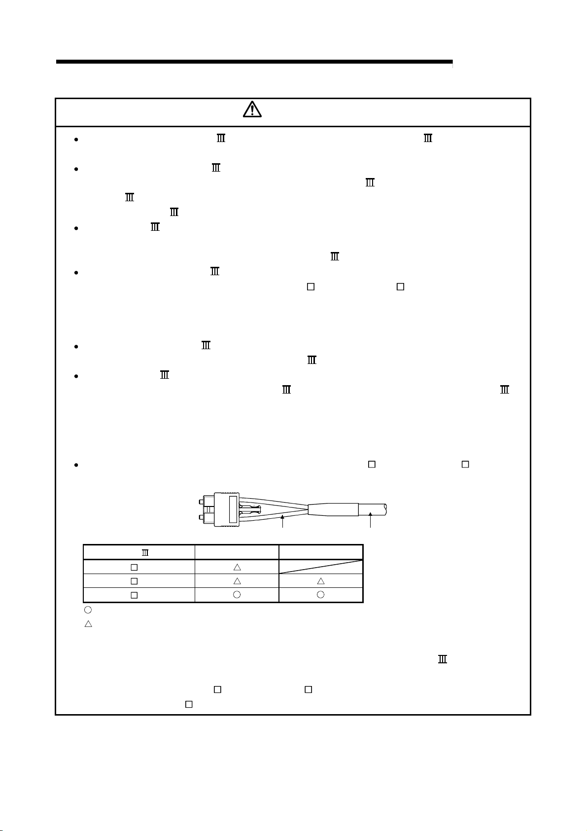
4 INSTALLATION, WIRING AND MAINTENANCE OF THE PRODUCT
MELSEC-Q
CAUTION
After removal of the SSCNET cable, be sure to put a cap on the SSCNET connector.
Otherwise, adhesion of dirt deteriorates in characteristic and it may cause malfunctions.
Do not remove the SSCNET cable while turning on the power supply of QD75MH and servo
amplifier. Do not see directly the light generated from SSCNET
SSCNET
source of SSCNET
cable. When the light gets into eye, may feel something is wrong for eye. (The light
cable complies with class1 defined in JISC6802 or IEC60825-1.)
connector and the end of
If the SSCNET cable is added a power such as a major shock, lateral pressure, haul, sudden
bending or twist, its inside distorts or breaks, and optical transmission will not be available.
Be sure to take care enough so that the short SSCNET
cable is added a twist easily.
Be sure to use the SSCNET cable within the range of operating temperature described in this
manual. Especially, as optical fiber for MR-J3BUS
M and MR-J3BUS M-A are made of
synthetic resin, it melts down if being left near the fire or high temperature. Therefore, do not
make it touched the part which becomes high temperature, such as radiator or regenerative
option of servo amplifier, or servomotor.
When laying the SSCNET cable, be sure to secure the minimum cable bend radius or more.
(Refer to this Section [2] Precautions for SSCNET
cable wiring.)
Put the SSCNET cable in the duct or fix the cable at the closest part to the QD75MH with
bundle material in order to prevent SSCNET
cable from putting its own weight on SSCNET
connector. When laying cable, the optical cord should be given loose slack to avoid from
becoming smaller than the minimum bend radius, and it should not be twisted.
Also, fix and hold it in position with using cushioning such as sponge or rubber which does not
contain plasticizing material.
Migrating plasticizer is used for vinyl tape. Keep the MR-J3BUS M, and MR-J3BUS M-A
cables away from vinyl tape because the optical characteristic may be affected.
SSCNET cable Cord Cable
MR-J3BUS M
MR-J3BUS M-A
MR-J3BUS M-B
: Normally, cable is not affected by plasticizer.
: Phthalate ester plasticizer such as DBP and DOP may affect optical characteristic of cable.
Optical cord
Cable
Generally, soft polyvinyl chloride (PVC), polyethylene resin (PE) and fluorine resin contain nonmigrating plasticizer and they do not affect the optical characteristic of SSCNET
cable.
However, some wire sheaths and cable ties, which contain migrating plasticizer (phthalate
ester), may affect MR-J3BUS
In addition, MR-J3BUS
M and MR-J3BUS M-A cables (made of plastic).
M-B cable (made of quartz glass) is not affected by plasticizer.
4 - 11

4 INSTALLATION, WIRING AND MAINTENANCE OF THE PRODUCT
MELSEC-Q
CAUTION
If the adhesion of solvent and oil to the cord part of SSCNET cable may lower the optical
characteristic and machine characteristic. If it is used such an environment, be sure to do the
protection measures to the cord part.
When keeping the QD75MH or servo amplifier, be sure to put on a cap to connector part so that
a dirt should not adhere to the end of SSCNET
connector.
SSCNET connector to connect the SSCNET cable is put a cap to protect light device inside
connector from dust. For this reason, do not remove a cap until just before connecting
SSCNET
cable. Then, when removing SSCNET cable, make sure to put a cap.
Keep the cap and the tube for protecting light cord end of SSCNET cable in a plastic bag with
a zipper of SSCNET
cable to prevent them from becoming dirty.
When exchanging the QD75MH or servo amplifier, make sure to put cap on SSCNET
connector. When asking repair of QD75MH or servo amplifier for some troubles, make also sure
to put a cap on SSCNET
connector. When the connector is not put a cap, the light device may
be damaged at the transit. In this case, exchange and repair of light device is required.
[1] Precautions for wiring
(1) Use separate cables for connecting to the QD75MH and for the power cable
that create surge and inductance.
(2) The shielded cable for connecting QD75MH can be secured in duct or
bundle fixing.
If the shielded cable is not secured, unevenness or movement of the
shielded cable or careless pulling on it could result in damage to the
QD75MH or servo amplifier or shielded cable or defective cable connections
could cause mis-operation of the unit.
(3) If a duct is being used and cables to connect to QD75MH are separated
from the power line duct, use metal piping.
Ground the pipes securely after metal piping.
(4) The cable is to use the twisted pair shielded cable (wire size 0.3 mm
shielded must be grounded on the QD75MH side.
(5) Use separate shielded cables of the forced stop input signal (EMI,
EMI.COM), limit signal (FLS, RLS, DOG, STOP, CHG, COM) and etc., and
manual pulse generator signal (PULSER A+, PULSER A-, PULSER B+,
PULSER B-, P5, SG) for connecting to the QD75MH.
They can cause electrical interference, surges and inductance that can lead
to mis-operation.
2
). The
4 - 12

4 INSTALLATION, WIRING AND MAINTENANCE OF THE PRODUCT
[Wiring example of shielded cable]
The following shows a wiring example for noise reduction in the case where the
connector A6CON1 is used.
Connector
(A6CON1)
For forced stop
input signal
Shielded
cable
For limit signal
and etc.
For manual paluse
generator signal
MELSEC-Q
To QD75MH
The length between the connector and the shielded
cables should be the shortest possible.
Use the shortest possible length to
ground the 2mm or more FG wire.
(The shield must be grounded on
the QD75MH side.)
4 - 13

s
4 INSTALLATION, WIRING AND MAINTENANCE OF THE PRODUCT
[Processing example of shielded cables]
Connections of FG wire and each shielded cable
Coat the wire with
insulaing tape.
Remove the covering from all shielded cables and bind
th e appeare d shiel d w ith a c o nduc t i ve tape .
Solder the shield of any one of the
shielded cables to the FG wire.
MELSEC-Q
Assembling of connector (A6CON1)
Wrap the coated part
with a heat contractile
tube.
4 - 14

4 INSTALLATION, WIRING AND MAINTENANCE OF THE PRODUCT
(5) To make this product conform to the EMC directive and low voltage
instruction, be sure to used of a AD75CK type cable clamp (manufactured
by Mitsubishi Electric) for grounding connected to the control box and the
shielded cable.
Inside control box
QD75MH
20cm(7.88inch)
to 30cm(11.82inch)
AD75CK
MELSEC-Q
[How to ground shielded cable using AD75CK]
Shielded cable
Shield
Ground terminal
Ground terminal installation screw (M4 8 screw)
Installation screw to control box (M4 screw)
Using the AD75CK, you can tie four cables of about 7mm outside diameter together for
grounding.
4 - 15
4 INSTALLATION, WIRING AND MAINTENANCE OF THE PRODUCT
[Wiring examples using duct (incorrect example and corrected example)]
Relay
Relay
MELSEC-Q
Wiring duct
Control panel
Control panel
Servo
amplifier
Noise source
(Power system,
Noise source
(Power system,
Servo
amplifier
etc.)
Changed
Relay Relay
etc.)
Servo
amplifier
Relay
PLC
Relay
PLC
QD
75
MH
QD
75
MH
Servo
amplifier
The servo amplifiers are placed
near the noise source.
The connection cable between
the QD75MH and servo amplifiers
is too long.
Wiring duct
The QD75MH and servo amplifiers
are placed closely. The connection
cable between the QD75MH and
servo amplifier is separately laid
from the power line (in this example,
the cable is outside of the duct) and
is as short as possible.
4 - 16

4 INSTALLATION, WIRING AND MAINTENANCE OF THE PRODUCT
MELSEC-Q
4.4 Confirming the installation and wiring
4.4.1 Items to confirm when installation and wiring are completed
Check the following points when completed with the QD75MH installation and wiring.
•
Is the module correctly wired? ... "Connection confirmation"
With "connection confirmation", the following three points are confirmed using GX
Configurator-QP's connection confirmation function. (GX Configurator-QP is
Important
If the QD75MH is faulty, or when the required signals such as the near-point dog signal and stop signal
are not recognized, unexpected accidents such as "not decelerating at the near-point dog during
machine OPR and colliding with the stopper", or "not being able to stop with the stop signal" may occur.
The "connection confirmation" must be carried out not only when structuring the positioning system, but
also when the system has been changed with module replacement or rewiring, etc.
required for this "connection confirmation".)
•
Are the QD75MH and servo amplifier correctly connected?
•
Are the servo amplifier and servomotor correctly connected?
•
Are the QD75MH and external device (input/output signal) correctly
connected?
With this "connection confirmation", "whether the direction that the QD75MH
recognizes as forward run matches the address increment direction in the actual
positioning work", and "whether the QD75MH recognizes the external
input/output signals such as the near-point dog signal and stop signal" can be
checked.
Refer to GX Configurator-QP Operating Manual for details on "Connection
confirmation".
Note that the monitor data of the "
Developer may also be used to "confirm the connection between the QD75MH
and external device (input signals)".
Md.30
External input signal" in the GX
4 - 17
 Loading...