

Page 1

Type QD75P/QD75D Positioning Module
Mitsubishi Programmable
Logic Controller
QD75P1
QD75P2
QD75P4
QD75D1
QD75D2
QD75D4
Page 2

Page 3
SAFETY INSTRUCTIONS
(Always read these instructions before using this equipment.)
Before using this product, please read this manual and the relevant manuals introduced in this manual
carefully and pay full attention to safety to handle the product correctly.
The instructions given in this manual are concerned with this product. For the safety instructions of the
programmable logic controller system, please read the CPU module User's Manual.
In this manual, the safety instructions are ranked as "DANGER" and "CAUTION".
DANGER
!
CAUTION
!
Note that the !CAUTION level may lead to a serious consequence according to t he circumstances.
Always follow the instructions of both levels because they are important to personal safety.
Please save this manual to make it accessible when required and always forw ard it to the end user.
Indicates that incorrect handling may cause hazardous conditions,
resulting in death or severe injur y.
Indicates that incorrect handling may cause hazardous conditions,
resulting in medium or slight personal injury or physical damage.
[Design Instructions]
!
DANGER
Provide a safety circuit outside the programmable logic controller so that the entire system will
operate safely even when an external power supply error or PLC fault occurs.
Failure to observe this could lead to accidents for incorrect outputs or malfunctioning.
(1) Configure an emergency stop circuit and interlock circuit such as a positioning upper
limit/lower limit to prevent mechanical damage outside t he PLC.
(2) The machine OPR operation is controlled by the OPR direction and OPR speed data.
Deceleration starts when the near-point dog turns ON. Thus, if the OPR direction is
incorrectly set, deceleration will not start and the machine will continue t o tr avel. Configure
an interlock circuit to prevent mechanical damage outside the PLC.
(3) When the module detects an error, normally deceleration st op or sudden stop w ill take
place according to the parameter stop group settings.
Set the parameters to the positioning system specifications.
Make sure that the OPR parameter and positioning data are within the parameter setting
values.
A - 1
Page 4
[Design Instructions]
!
CAUTION
Do not bundle or adjacently lay the control wire or communication cable with the main circuit or
power wire.
Separate these by 100mm (3.94in.) or more.
Failure to observe this could lead to malfunctioning caused by noise.
[Mounting Instructions]
!
CAUTION
Use the PLC within the general specifications environment giv en in this manual.
Using the PLC outside the general specification range environ ment could lead to electr ic
shocks, fires, malfunctioning, product damage or deterioration.
While pressing the installation lever located at the bottom of module, insert the module fixing
tab into the fixing hole in the base unit until it stops. Then, securely mount the module with the
fixing hole as a supporting point.
Incorrect loading of the module can cause a malfunction, failure or drop.
When using the PLC in the environment of much vibration, tighten the module with a screw.
Tighten the screw in the specified torque range.
Undertightening can cause a drop, short circuit or malfunction.
Overtightening can cause a drop, short circuit or malfunction due to damage to the screw or
module.
Completely turn off the externally supplied power used in the system before mounting or
removing the module.
Not doing so may damage the product.
[Wiring Instructions]
!
DANGER
Always confirm the terminal layout before connecting the wires to the module.
[Startup/Maintenance Instructions]
!
DANGER
Completely turn off the externally supplied power used in the system before cleaning or
tightening the screws.
Failure to turn all phases OFF could lead to electric shocks.
A - 2
Page 5
[Startup/Maintenance Instructions]
!
CAUTION
Never disassemble or modify the module.
Failure to observe this could lead to trouble, malfunctioning, injuries or fires.
Completely turn off the externally supplied power used in the system before installing or
removing the module.
Failure to turn all phases OFF could lead to module trouble or malfunctioning.
Do not mount/remove the module onto/from the base unit more than 50 times (IEC61131-2-
compliant), after the first use of the product. Failure to do so may cause malfunction.
Before starting test operation, set the parameter speed limit value to the slowest value, and
make sure that operation can be stopped immediately if a hazardous state occurs.
Always make sure to touch the grounded metal to discharge the electricity charged in t he body,
etc., before touching the module.
Failure to do so may cause a failure or malfunctions of the module.
[Precautions for use]
!
CAUTION
Note that when the reference axis speed is designated for interpolation operation, the speed of
the partner axis (2nd axis, 3rd axis and 4th axis) may be larger than the set speed (larger than
the speed limit value).
[Disposal Instructions]
!
CAUTION
When disposing of the product, handle it as industrial waste.
A - 3
Page 6

REVISIONS
The manual number is given on the bottom left of the back cov er
Manual Number Revision
Print Date
Dec., 1999 SH (NA)-08005 8-A First edition
Oct., 2000 SH (NA)-080058-B Addition of function version B
(Overall revisions based on the Japanese Manual Version
SH-080047-E)
Jun., 2001 SH (NA)-080058-C The software package names (GPP function software package,
QD75 software package) have been replaced by the product names
(GX Developer, GX Configurator-QP) for standardization.
Partial corrections and additions
CONTENTS, About Manuals, Generic Terms and Abbreviations,
Section 1.4, Section 2.2, Section 2.3, Section 3.2.2 to Section 3.2.4,
Section 3.3.2, Section 3.3.3, Section 3.4.1, Section 3.4.3, Section
3.4.4, Section 4.1.2, Section 4.3, Section 5.1.2, Section 5.1.3, Section
5.2.3, Section 5.2.5, Section 5.6.2, Section 5.7.1, Section 6.2 to
Section 6.4, Section 6.5.3, Section 7.2, Section 8.2.2, Section 8.2.5,
Section 8.2.6, Section 9.1.2, Section 9.2.1, Section 9.2.16, Section
9.2.17, Section 10.3.2, Section 10.6.2, Section 11.2.3, Section 11.3.3,
Section 11.3.4, Section 11.4.3, Section 12.1.1, Section 12.5 to Section
12.7, Section 13.1, Section 13.3, Section 13.4, Section 14.2 to Section
14.7, Section 15.1, Section 15.2, Section 15.4, Appendix 1, Appendix
9.2, Appendix 11, INDEX
.
Apr., 2003 SH (NA)-080058-D
Oct., 2003 SH (NA)-080058-E
Partial corrections and additions
SAFETY INSTRUCTIONS, CONTENTS, Component List,
Section 1.2.3, Section 1.4, Section 2.3, Section 2.4, Section 3.1,
Section 3.2.1, Section 3.2.3, Section 3.2.4, Section 3.4.1, Section
3.4.4, Section 4.1.2, Section 4.3.1, Section 4.3.2, Section 5.1.1,
Section 5.1.7, Section 5.1.8, Section 5.2.1, Section 5.2.4, Section
5.6.2, Section 5.7.1, Section 6.4, Section 6.5.4, Section 6.5.6, Section
8.2.3 to Section 8.2.8, Section 9.2.17, Section 9.2.19, Section 11.2.1,
Section 11.3.1, Section 11.4.1, Section 12.1.1, Section 12.5.1, Section
12.5.2, Section 12.7.3, Section 12.7.5, Section 12.7.9, Section 14.4,
Section 15.2, Appendix 1.1, Appendix 4.1 to Appendix 4.3, Appendix
7.1, Appendix 9.2, Appendix 10 to Appendix 13, INDEX
Partial correcti on s an d ad di t ion s
CONTENTS, Section 1.1.1, Section 1.4, Section 2.2, Section 2.4,
Section 3.2.1, Section 3.2.3, Section 3.2.4, Section 3.3.2, Section
3.4.3, Section 3.4.4, Section 5.1.1, Section 5.1.8, Section 5.7.1,
Section 6.5.3, Section 6.5.6, Section 7.1.2, Section 9.1.2, Section
9.2.3 to Section 9.2.9, Section 11.2.1, Section 11.3.1, Section 11.4.1,
Section 12.2.1, Section 12.7.10, Appendix 9.2, Appendix 12, INDEX
A - 4
Page 7
REVISIONS
Manual Number Revision
Print Date
Feb., 2004 SH (NA)-080058-F
The manual number is given on the bottom left of the back cov er
Partial corrections and additions
CONTENTS, Section 3.4.1, Section 3.4.3, Section 3.4.4,
Section 5.2.1, Section 5.4, Section 5.5, Section 5.6.2, Section 8.2.6,
Section 10.1.2, Section 10.3.3, Section 10.3.5, Section 10.3.7,
Appendix 9.2, Appendix 12
.
Nov., 2004 S H (NA ) -080 05 8 - G
Jun., 2005 SH (NA)-080058-H
Partial correcti on s an d ad di t ion s
SAFETY INSTRUCTIONS, Section 1.4, Section 2.3, Section 2.4,
Section 4.2.1, Section 4.3.1, Section 4.5.1, Section 5.1.7,
Section 5.2.1, Section 5.2.6, Section 5.6.2, Section 6.1,
Section 9.2.19, Section 12.2.1, Section 12.4.4, Section 12.7.4,
Appendix 1.1, Appendix 9.1
Partial correcti on s an d ad di t ion s
Section 5.1.2, Section 9.1.2, Section 9.2.10, Section 9.2.21,
Section 10.3.8, Section 11.4.1, Section 12.5.2, Section 12.7.1,
Section 12.7.6, Section 15.1, Section 15.2
Japanese Manual Version SH-0800047-L
This manual confers no industrial property rights or any rights of any other kind, nor doe s it confer any patent licenses.
Mitsubishi Electric Corporation cannot be held responsible for any problems inv olv ing industria l property rights which
may occur as a result of using the contents noted in this manual.
1999 MITSUBISHI ELECTRIC CORPORATION
A - 5
Page 8

INTRODUCTION
Thank you for purchasing the Mitsubishi general-purpose programmable logic controller MELSEC-Q Series.
Always read through this manual, and fully comprehend the functions and performance of the Q Series PLC
before starting use to ensure correct usage of this product.
CONTENTS
SAFETY INSTRUCTIONS.............................................................................................................................A- 1
REVISIONS....................................................................................................................................................A- 4
INTRODUCTION ...........................................................................................................................................A- 6
CONTENTS....................................................................................................................................................A- 6
About Manuals ..............................................................................................................................................A- 13
Using This Manual.........................................................................................................................................A- 13
Conformation to the EMC AND LOW-VOLTAGE DIRECTIVES.................................................................A- 13
Generic Terms and Abbreviations................................................................................................................A- 14
Component List .............................................................................................................................................A- 15
Section 1 Product Specifications and Handling
1. Product Outline 1- 1 to 1- 22
1.1 Positioning control....................................................................................................................................1- 2
1.1.1 Features of QD75..............................................................................................................................1- 2
1.1.2 Purpose and applications of positioning control...............................................................................1- 5
1.1.3 Mechanism of positioning control .....................................................................................................1- 7
1.1.4 Outline design of positioning system................................................................................................1- 9
1.1.5 Communicating signals between QD75 and each module.............................................................1- 12
1.2 Flow of system operation........................................................................................................................1- 15
1.2.1 Flow of all processes........................................................................................................................1- 15
1.2.2 Outline of starting ...................................................................................................... .......................1- 18
1.2.3 Outline of stopping ...........................................................................................................................1- 20
1.2.4 Outline for restarting.........................................................................................................................1- 21
1.3 Restrictions with a system using a stepping motor................................................................................1- 22
1.4 Function additions/modifications according to function version B.........................................................1- 22
2. System Configuration 2- 1 to 2- 6
2.1 General image of system.........................................................................................................................2- 2
2.2 Component list .........................................................................................................................................2- 4
2.3 Applicable system....................................................................................................................................2- 5
2.4 How to check the function version and SERIAL No. .............................................................................2- 6
A - 6
Page 9

3. Specifications and Functions 3- 1 to 3- 24
3.1 Performance specifications......................................................................................................................3- 2
3.2 List of functions .......................................................................................................................................3- 4
3.2.1 QD75 control functions......................................................................................................................3- 4
3.2.2 QD75 main functions......................................................................................................................... 3- 6
3.2.3 QD75 sub functions and common functions ....................................................................................3- 8
3.2.4 Combination of QD75 main functions and sub functions................................................................3- 12
3.3 Specifications of input/output signals with PLC CPU.............................................................................3- 14
3.3.1 List of input/output signals with PLC CPU.......................................................................................3- 14
3.3.2 Details of input signals (QD75
3.3.3 Details of output signals (PLC CPU
3.4 Specifications of input/output interfaces with external devices .............................................................3- 17
3.4.1 Electrical specifications of input/output signals...............................................................................3- 17
3.4.2 Signal layout for external device connection connector..................................................................3- 19
3.4.3 List of input/output signal details......................................................................................................3- 20
3.4.4 Input/output interface internal circuit................................................................................................3- 22
4. Installation, Wiring and Maintenance of the Product 4- 1 to 4- 16
4.1 Outline of installation, wiring and maintenance....................................................................................... 4- 2
4.1.1 Installation, wiring and maintenance procedures.............................................................................4- 2
4.1.2 Names of each part...........................................................................................................................4- 3
4.1.3 Handling precautions ........................................................................................................................4- 5
4.2 Installation ................................................................................................................................................4- 7
4.2.1 Precautions for installation................................................................................................................4- 7
4.3 Wiring........................................................................................................................................................4- 8
4.3.1 Precautions for wiring........................................................................................................................4- 8
4.3.2 Wiring of the differential driver common terminal............................................................................4- 13
4.4 Confirming the installation and wiring.....................................................................................................4- 14
4.4.1 Items to confirm when installation and wiring are completed.........................................................4- 14
4.5 Maintenance............................................................................................................................................4- 15
4.5.1 Precautions for maintenance...........................................................................................................4- 15
4.5.2 Disposal instructions ........................................................................................................................4- 15
PLC CPU) ..................................................................................3- 15
QD75)................................................................................3- 16
5. Data Used for Positioning Control (List of buffer memory addresses) 5- 1 to 5-132
5.1 Types of data............................................................................................................................................5- 2
5.1.1 Parameters and data required for control.........................................................................................5- 2
5.1.2 Setting items for positioning parameters..........................................................................................5- 4
5.1.3 Setting items for OPR parameters....................................................................................................5- 6
5.1.4 Setting items for positioning data......................................................................................................5- 7
5.1.5 Setting items for block start data .....................................................................................................5- 10
5.1.6 Setting items for condition data .......................................................................................................5- 11
5.1.7 Types and roles of monitor data......................................................................................................5- 12
5.1.8 Types and roles of control data .......................................................................................................5- 16
A - 7
Page 10

5.2 List of parameters ...................................................................................................................................5- 20
5.2.1 Basic parameters 1 ..........................................................................................................................5- 20
5.2.2 Basic parameters 2 ..........................................................................................................................5- 26
5.2.3 Detailed parameters 1......................................................................................................................5- 28
5.2.4 Detailed parameters 2......................................................................................................................5- 36
5.2.5 OPR basic parameters.....................................................................................................................5- 46
5.2.6 OPR detailed parameters ................................................................................................................5- 54
5.3 List of positioning data ............................................................................................................................5- 58
5.4 List of block start data .............................................................................................................................5- 74
5.5 List of condition data...............................................................................................................................5- 80
5.6 List of monitor data..................................................................................................................................5- 86
5.6.1 System monitor data ........................................................................................................................5- 86
5.6.2 Axis monitor data..............................................................................................................................5- 96
5.7 List of control data..................................................................................................................................5-110
5.7.1 System control data.........................................................................................................................5-110
5.7.2 Axis control data..............................................................................................................................5-112
6. Sequence Program Used for Positioning Control 6- 1 to 6- 44
6.1 Precautions for creating program............................................................................................................6- 2
6.2 List of devices used..................................................................................................................................6- 5
6.3 Creating a program .................................................................................................................................6- 11
6.3.1 General configuration of program....................................................................................................6- 11
6.3.2 Positioning control operation program.............................................................................................6- 12
6.4 Positioning program examples...............................................................................................................6- 15
6.5 Program details.......................................................................................................................................6- 24
6.5.1 Initialization program ........................................................................................................................6- 24
6.5.2 Start details setting program............................................................................................................6- 25
6.5.3 Start program....................................................................................................................................6- 27
6.5.4 Continuous operation interrupt program..........................................................................................6- 37
6.5.5 Restart program ...............................................................................................................................6- 39
6.5.6 Stop program....................................................................................................................................6- 42
7. Memory Configuration and Data Process 7- 1 to 7- 12
7.1 Configuration and roles of QD75 memory...............................................................................................7- 2
7.1.1 Configuration and roles of QD75 memory........................................................................................7- 2
7.1.2 Buffer memory area configuration ....................................................................................................7- 5
7.2 Data transmission process ......................................................................................................................7- 6
A - 8
Page 11

Section 2 Control Details and Setting
8. OPR Control 8- 1 to 8- 22
8.1 Outline of OPR control.............................................................................................................................8- 2
8.1.1 Two types of OPR control.................................................................................................................8- 2
8.2 Machine OPR...........................................................................................................................................8- 4
8.2.1 Outline of the machine OPR operation.............................................................................................8- 4
8.2.2 Machine OPR method.......................................................................................................................8- 5
8.2.3 OPR method (1): Near-point dog method ........................................................................................8- 6
8.2.4 OPR method (2): Stopper method 1) ...............................................................................................8- 8
8.2.5 OPR method (3): Stopper method 2) ..............................................................................................8- 11
8.2.6 OPR method (4): Stopper method 3) ..............................................................................................8- 14
8.2.7 OPR method (5): Count method 1)..................................................................................................8- 16
8.2.8 OPR method (6): Count method 2)..................................................................................................8- 18
8.3 Fast OPR.................................................................................................................................................8- 20
8.3.1 Outline of the fast OPR operation....................................................................................................8- 20
9. Major Positioning Contro l 9- 1 to 9-114
9.1 Outline of major positioning controls .......................................................................................................9- 2
9.1.1 Data required for major positioning control ......................................................................................9- 4
9.1.2 Operation patterns of major positioning controls .............................................................................9- 5
9.1.3 Designating the positioning address................................................................................................9- 15
9.1.4 Confirming the current value............................................................................................................9- 16
9.1.5 Control unit "degree" handling.........................................................................................................9- 18
9.1.6 Interpolation control..........................................................................................................................9- 21
9.2 Setting the positioning data ...................................................................................................................9- 25
9.2.1 Relation between each control and positioning data ......................................................................9- 25
9.2.2 1-axis linear control ..........................................................................................................................9- 27
9.2.3 2-axis linear interpolation control.....................................................................................................9- 29
9.2.4 3-axis linear interpolation control.....................................................................................................9- 33
9.2.5 4-axis linear interpolation control.....................................................................................................9 -39
9.2.6 1-axis fixed-feed control...................................................................................................................9- 43
9.2.7 2-axis fixed-feed control (interpolation) ...........................................................................................9- 45
9.2.8 3-axis fixed-feed control (interpolation) ...........................................................................................9- 47
9.2.9 4-axis fixed-feed control (interpolation) ..........................................................................................9- 51
9.2.10 2-axis circular interpolation control with sub point designation.....................................................9- 53
9.2.11 2-axis circular interpolation control with center point designation................................................9- 59
9.2.12 1-axis speed control.......................................................................................................................9- 67
9.2.13 2-axis speed control.......................................................................................................................9- 70
9.2.14 3-axis speed control.......................................................................................................................9- 73
9.2.15 4-axis speed control.......................................................................................................................9- 77
9.2.16 Speed-position switching control (INC mode)...............................................................................9- 82
9.2.17 Speed-position switching control (ABS mode)..............................................................................9- 90
9.2.18 Position-speed switching control ...................................................................................................9- 98
9.2.19 Current value changing.................................................................................................................9-105
A - 9
Page 12

9.2.20 NOP instruction .............................................................................................................................9-110
9.2.21 JUMP instruction...........................................................................................................................9-111
9.2.22 LOOP.............................................................................................................................................9-113
9.2.23 LEND .............................................................................................................................................9-114
10. High-Level Positioning Control 10- 1 to 10- 26
10.1 Outline of high-level positioning control...............................................................................................10- 2
10.1.1 Data required for high-level positioning control............................................................................10- 3
10.1.2 " Block start data" and "condition data" configuration.................................................................. 10- 4
10.2 High-level positioning control execution procedure ...........................................................................10- 6
10.3 Setting the block start data..................................................................................................................10- 7
10.3.1 Relation between various controls and block start data ..............................................................10- 7
10.3.2 Block start (normal start) ..............................................................................................................10- 8
10.3.3 Condition start ..............................................................................................................................10- 10
10.3.4 Wait start.......................................................................................................................................10- 11
10.3.5 Simultaneous start ......................................................................................................................10- 12
10.3.6 Repeated start (FOR loop) ..........................................................................................................10- 13
10.3.7 Repeated start (FOR condition) ..................................................................................................10- 14
10.3.8 Restrictions when using the NEXT start......................................................................................10- 15
10.4 Setting the condition data...................................................................................................................10- 16
10.4.1 Relation between various controls and the condition data.........................................................10- 16
10.4.2 Condition data setting examples .................................................................................................10- 19
10.5 Multiple axes simultaneous start control............................................................................................10- 20
10.6 Start program for high-level positioning control .................................................................................10- 23
10.6.1 Starting high-level positioning control..........................................................................................10- 23
10.6.2 Example of a start program for high-level positioning control.....................................................10- 24
11. Manual Control 11- 1 to 11- 36
11.1 Outline of manual control ....................................................................................................................11- 2
11.1.1 Three manual control methods.....................................................................................................11- 2
11.2 JOG operation......................................................................................................................................11- 4
11.2.1 Outline of JOG operation..............................................................................................................11- 4
11.2.2 JOG operation execution procedure ............................................................................................11- 7
11.2.3 Setting the required parameters for JOG operation.....................................................................11- 8
11.2.4 Creating start programs for JOG operation.................................................................................11- 10
11.2.5 JOG operation example...............................................................................................................11- 13
11.3 Inching operation.................................................................................................................................11- 17
11.3.1 Outline of inching operation.........................................................................................................11- 17
11.3.2 Inching operation execution procedure.......................................................................................11- 20
11.3.3 Setting the required parameters for inching operation................................................................11- 21
11.3.4 Creating a program to enable/disable the inching operation......................................................11- 22
11.3.5 Inching operation example...........................................................................................................11- 25
11.4 Manual pulse generator operation......................................................................................................11- 27
11.4.1 Outline of manual pulse generator operation..............................................................................11- 27
11.4.2 Manual pulse generator operation execution procedure............................................................11- 31
11.4.3 Setting the required parameters for manual pulse generator operation ....................................11- 32
A - 10
Page 13

11.4.4 Creating a program to enable/disable the manual pulse generator operation ..........................11- 33
12. Control Sub Functions 12- 1 to 12- 98
12.1 Outline of sub functions .......................................................................................................................12- 2
12.1.1 Outline of sub functions.................................................................................................................12- 2
12.2 Sub functions specifically for machine OPR.......................................................................................12- 4
12.2.1 OPR retry function.........................................................................................................................12- 4
12.2.2 OP shift function ...........................................................................................................................12- 8
12.3 Functions for compensating the control .............................................................................................12- 11
12.3.1 Backlash compensation function.................................................................................................12- 11
12.3.2 Electronic gear function................................................................................................................12- 13
12.3.3 Near pass function .......................................................................................................................12- 18
12.4 Functions to limit the control...............................................................................................................12- 21
12.4.1 Speed limit function......................................................................................................................12- 21
12.4.2 Torque limit function.....................................................................................................................12- 23
12.4.3 Software stroke limit function.......................................................................................................12- 26
12.4.4 Hardware stroke limit function .....................................................................................................12- 32
12.5 Functions to change the control details..............................................................................................12- 34
12.5.1 Speed change function ................................................................................................................12- 34
12.5.2 Override function..........................................................................................................................12- 41
12.5.3 Acceleration/deceleration time change function .........................................................................12- 44
12.5.4 Torque change function ...............................................................................................................12- 48
12.6 Absolute position restoration function ................................................................................................12- 50
12.7 Other functions....................................................................................................................................12- 58
12.7.1 Step function.................................................................................................................................12- 58
12.7.2 Skip function.................................................................................................................................12- 63
12.7.3 M code output function.................................................................................................................12- 66
12.7.4 Teaching function.........................................................................................................................12- 70
12.7.5 Target position change function...................................................................................................12- 77
12.7.6 Command in-position function.....................................................................................................12- 81
12.7.7 Acceleration/deceleration processing function............................................................................12- 84
12.7.8 Pre-reading start function.............................................................................................................12- 87
12.7.9 Deceleration start flag function ....................................................................................................12- 92
12.7.10 Stop command processing for deceleration stop function........................................................12- 96
13. Common Functions 13- 1 to 13- 8
13.1 Outline of common functions...............................................................................................................13- 2
13.2 Parameter initialization function...........................................................................................................13- 3
13.3 Execution data backup function...........................................................................................................13- 5
13.4 External I/O signal logic switching function.........................................................................................13- 7
13.5 External I/O signal monitor function ....................................................................................................13- 8
14. Dedicated instructions 14- 1 to 14- 22
14.1 List of dedicated instructions ...............................................................................................................14- 2
14.2 Interlock during dedicated instruction is executed..............................................................................14- 2
14.3 ABRST1, ABRST2, ABRST3, ABRST4..............................................................................................14- 3
A - 11
Page 14

14.4 PSTRT1, PSTRT2, PSTRT3, PSTRT4...............................................................................................14- 8
14.5 TEACH1, TEACH2, TEACH3, TEACH4............................................................................................14- 12
14.6 PFWRT................................................................................................................................................14- 16
14.7 PINIT ...................................................................................................................................................14- 20
15. Troubleshooting 15- 1 to 15- 38
15.1 Error and warning details.....................................................................................................................15- 2
15.2 List of errors .........................................................................................................................................15- 6
15.3 List of warnings ...................................................................................................................................15- 32
15.4 LED display functions .........................................................................................................................15- 38
Appendices Appendix- 1 to Appendix-108
Appendix 1 Version up of the functions............................................................................................Appendix- 2
Appendix 1.1 Comparison of functions according to function versions.......................................Appendix- 2
Appendix 2 Format sheets................................................................................................................Appendix- 4
Appendix 2.1 Positioning Module operation chart .......................................................................Appendix- 4
Appendix 2.2 Parameter setting value entry table .......................................................................Appendix- 6
Appendix 2.3 Positioning data setting value entry table ............................................................Appendix- 12
Appendix 3 Positioning data (No. 1 to 600) List of buffer memory addresses...............................Appendix- 13
Appendix 4 Connection examples with servo amplifiers manufactured by MITSUBISHI Electric Corporation
.......................................................................................................................................Appendix- 37
Appendix 4.1 Connection example of QD75D
Appendix 4.2 Connection example of QD75D and MR-J2/J2S- A (Differential driver) .....Appendix- 38
Appendix 4.3 Connection example of QD75D
Appendix 5 Connection examples with stepping motors manufactured by ORIENTALMOTOR Co., Ltd.
.......................................................................................................................................Appendix- 40
Appendix 5.1 Connection example of QD75P
Appendix 6 Connection examples with servo amplifiers manufactured by Matsushita Electric Industrial Co.,
Ltd. ................................................................................................................................Appendix- 41
Appendix 6.1 Connection example of QD75D
Appendix 7 Connection examples with servo amplifiers manufactured by SANYO DENKI Co., Ltd.
.......................................................................................................................................Appendix- 42
Appendix 7.1 Connection example of QD75D
Appendix 8 Connection examples with servo amplifiers manufactured by YASKAWA Electric Corporation
.......................................................................................................................................Appendix- 43
Appendix 8.1 Connection example of QD75D
Appendix 9 Comparisons with conventional positioning modules..................................................Appendix- 44
Appendix 9.1 Comparisons with A1SD71S2 model....................................................................Appendix- 44
Appendix 9.2 Comparisons with A1SD75P1-S3/A1SD75P2-S3/ A1SD75P3-S3 models.........Appendix- 45
Appendix 10 MELSEC Explanation of positioning terms................................................................Appendix- 68
Appendix 11 Positioning control troubleshooting............................................................................Appendix- 92
Appendix 12 List of buffer memory addresses.................................................................................Appendix-98
Appendix 13 External dimension drawing......................................................................................Appendix-107
and MR-H A (Differential driver) ...............Appendix- 37
and MR-C A (Differential driver) ...............Appendix- 39
and VEXTA UPD (Open collector)................Appendix- 40
and MINAS-A series (Differential driver)......Appendix- 41
and PYO series (Differential driver)..............Appendix- 42
and Σ- series (Differential driver) .................Appendix- 43
A - 12
Page 15
About Manuals
Related Manu al s
The following manuals are also related to this product.
In necessary, order them by quoting the details in the tables below.
Manual Name
Type QD75P/QD75D Positioning Module User's Manual
(Hardware)
Describes the performance, specifications, I/O interface, component names, and startup procedure of
the respective positioning modules: QD75P1, QD75P2, QD75P4, QD75D1, QD75D2, and QD75D4.
(The manual is supplied with the module.)
GX Configurator-QP Operating Manual
Describes how to use GX Configurator-QP for the following and other purposes: creating data
(parameters, positioning data, etc.), sending the data to the module, monitoring the positioning
operations, and testing. (The manual is supplied with the software.)
Using This Manual
The symbols used in this manual are shown below.
Pr.
Da.
........ Symbol indicating positioning parameter and OPR parameter item.
....... Symbol indicating positioning data, block start data and condition
data item.
Md.
Cd.
....... Symbol indicating m onitor dat a item.
....... Symbol indicating control data item.
Manual Number
(Model Code)
IB-0800063
(13JQ73)
SH-080172
(13JU19)
(A serial No. is inserted in the
mark.)
Representation of numerical values used in this manual.
Buffer memory addresses, error codes and warning codes are represented in
decimal.
X/Y devices are represented in hexadecimal.
Setting data and monitor data are represented in decimal or hexadecimal. Data
ended by "H" are represented in hexadecimal.
(Example) 10.........Decimal
10H......Hexadecimal
Conformation to the EMC AND LOW-VOLTAGE DIRECTIVES
For details on making Mitsubishi PLC conform to the EMC and Low Voltage
Directives when installing it in your product, please refer to Chapter 3, “EMC AND
LOW-VOLTAGE DIRECTIVES” of the using PLC CPU module User’s Manual
(Hardware).
The CE logo is printed on the rating plate on the main body of the PLC that
conforms to the
EMC and Low Voltage Directives
To make this product conform to the
refer to Section 4.3.1 "Precautions for wiring".
A - 13
.
EMC and Low Voltage Directives
, please
Page 16

Generic Terms and Abbreviations
Unless specially noted, the following generic terms and abbreviations are used in this
manual.
Generic term/abbreviation Details of generic term/abbreviation
PLC CPU Generic term for PLC CPU on which QD75 can be mounted.
QD75 Generic term for positioning module QD75P1, QD75P2, QD75P4, QD75D 1, QD75D 2, and
QD75D4.
The module type is described to indicate a specifi c modul e.
Peripheral device Generic term for DOS/V personal computer that can run the following "GX D ev eloper" and "GX
Configurator-QP".
GX Configurator-QP Abbreviation for GX Configurator-QP (SW2D5C-QD75P-E or later).
GX Developer Abbreviation for GX Developer (SW4D5C-GPPW-E or later).
Drive unit (servo amplifier) Abbreviation for pulse input compatible drive unit (servo amplifier).
Manual pulse generator Abbreviation for manual pulse generator (prepared by user).
DOS/V personal computer
Personal computer Generic term for DOS/V personal computer.
Workpiece Generic term for moving body such as workpiece and tool, and for v arious control targ ets.
Axis 1, axis 2, axis 3,
axis 4
1-axis, 2-axis, 3-axis,
4-axis
IBM PC/AT
Indicates each axis connected to QD75.
Indicates the number of axes. (Example: 2-ax is = Indicates tw o ax es such as axis 1 and axis 2,
axis 2 and axis 3, and axis 3 and axis 1.)
®
and compatible DOS/V compliant personal computer.
A - 14
Page 17

Component List
The table below shows the component included in respective positioning modules:
Module name Description Quantity
QD75P1 QD75P1 Positioning Module(1-axis open collector output system) 1
QD75P2 QD75P2 Positioning Module(2-axes open collector output system) 1
QD75P4 QD75P4 Positioning Module(4-axes open collector output system) 1
QD75D1
QD75D2
QD75D4
QD75D1 Positioning Module(1-axis differential driver output system) 1
Differential driver common terminal 1
QD75D2 Positioning Module(2-axes differential driver output system) 1
Differential driver common terminal 1
QD75D4 Positioning Module(4-axes differential driver output system) 1
Differential driver common terminal 1
A - 15
Page 18

MEMO
A - 16
Page 19

Section 1 Product Specifications and Handling
Section 1 is configured for the following purposes (1) to (5).
(1) To understand the outline of positioning control, and the QD75 specifications
and functions
(2) To carry out actual work such as installation and wiring
(3) To set parameters and data required for positioning control
(4) To create a sequence program required for positioning control
(5) To understand the memory configuration and data transmission process
Section 1
Read Section 2 for details on each control.
Chapter 1 Product outline .............................................................................................. 1- 1 to 1- 22
Chapter 2 System configuration .................................................................................... 2- 1 to 2- 6
Chapter 3 Specifications and Functions........................................................................ 3- 1 to 3- 24
Chapter 4 Installation, Wiring and Maintenance of the Product................................... 4- 1 to 4- 16
Chapter 5 Data Used for Positioning Control................................................................ 5- 1 to 5-132
Chapter 6 Sequence Program Used for Positioning Control........................................ 6- 1 to 6- 44
Chapter 7 Memory Configuration and Data Process.................................................... 7- 1 to 7- 12
Page 20

MEMO
Page 21

Chapter 1 Product Outline
The purpose and outline of positioning control using QD75 are explained in this chapter.
Reading this chapter will help you understand what can be done using the positioning
system and which procedure to use for a specific purpose.
1
By understanding "What can be done", and "Which procedure to use" beforehand, the
positioning system can be structured smoothly.
1.1 Positioning control........................................................................................................1- 2
1.1.1 Features of QD75 ...........................................................................................1- 2
1.1.2 Purpose and applications of positioning control ............................................1- 5
1.1.3 Mechanism of positioning control...................................................................1- 7
1.1.4 Outline design of positioning system .............................................................1- 9
1.1.5 Communicating signals between QD75 and each module ..........................1- 12
1.2 Flow of system operation ............................................................................................1- 15
1.2.1 Flow of all processes .....................................................................................1- 15
1.2.2 Outline of starting...........................................................................................1- 18
1.2.3 Outline of stopping.........................................................................................1- 20
1.2.4 Outline for restarting ......................................................................................1- 21
1.3 Restrictions with a system using a stepping motor....................................................1- 22
1.4 Function additions/modifications according to function version B.............................1- 22
1 - 1
Page 22

1 PRODUCT OUTLINE
1.1 Positioning control
1.1.1 Features of QD75
The features of the QD75 are shown below.
(1) Availability of one, two, and four axis modules
MELSEC-Q
(a) One, two and four axis modules are available for both the open collector
system pulse output (QD75P1, QD75P2, and QD75P4) and differential
driver system pulse output (QD75D1, QD75D2, and QD75D4), comprising
six different models.
A model is determined by the drive unit type and number of axes. (Refer to
Section 2.2.)
(b) For connecting any of the QD75 modules to the base unit, a single slot and
32 dedicated I /O chan nel s a re requ i red .
Within the limit imposed by the maximum number of inputs and outputs
supported by the PLC CPU, up to 64 modules can be used. (Refer to
Section 3.1.)
(2) Wide variety of positioning control functions
(a) A wide variety of positioning control functions essential to any positioning
system are supported: positioning to an arbitrary position, fixed-feed
control, equal-speed control, and so on. (Refer to Section 5.3 and 9.2.)
1) Up to 600 positioning data items, including such information as
positioning addresses, control systems, and operation patterns, can be
prepared for each axis.
Using the prepared positioning data, the positioning control is
performed independently for each axis. (In addition, such controls as
interpolation involving two to four axes and simultaneous startup of
multiple axes are possible.)
2) Independent control of each axis can be achieved in linear control
mode (executable simultaneously over four axes).
Such control can ei th e r be t he in de pe nden t po si tio ni ng con t rol u sing a
single positioning data or the continuous positioning control enabled by
the continuous processing of multiple positioning data.
3) Coordinated control over multiple axes can take the form of either the
linear interpolation through the speed or position control of two to four
axes or the circular interpolation involving two axes.
Such control can ei th e r be t he in de pe nden t po si tio ni ng con t rol u sing a
single positioning data or the continuous positioning control enabled by
the continuous processing of multiple positioning data.
(b) For each positioning data, the user can specify any of the following control
systems: position control, speed control, speed-position switching control,
position-speed switching control, and so on. (Refer to Section 5.3 and 9.2.)
1 - 2
Page 23

1 PRODUCT OUTLINE
MELSEC-Q
(c) Continuous positioning control using multiple positioning data can be
executed in accordance with the operation patterns the user assigned to
the positioning data. (Refer to Section 5.3 and 9.1.2)
Continuous positioning control can be executed over multiple blocks, where
each block consists of multiple positioning data. (Refer to Section 10.3.2.)
(d) OPR control is given additional features (Refer to Section 8.2.)
1) Six different machine OPR methods are provided: near point dog
method (one method), stopper methods (three methods), and count
methods (two methods).
2) OPR retry function facilitates the machine OPR control from an
arbitrary position.
(The machine OP a p remie r re fe ren ce po si t ion fo r positioning cont rol.
The machine is set to the machine OP through one of the machine
OPR methods mentioned in 1) above.)
(e) Two acceleration/deceleration control methods are provided: automatic
trapezoidal acceleration/deceleration and S-pattern
acceleration/deceleration. (Refer to Section 12.7.7.)
(The S-pattern acceleration/deceleration control is disabled if stepping
motors are used. Refer to Section 1.3.)
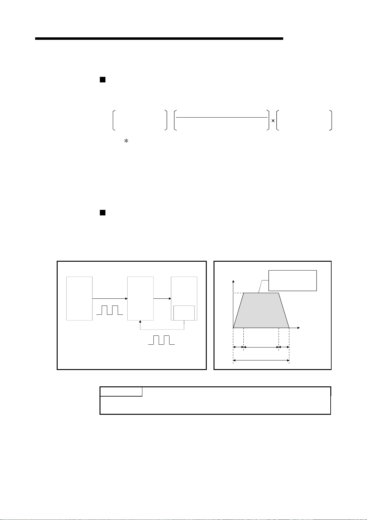
(3) Quick startup (Refer to Section 3.1.)
A positioning operation starts up quickly taking as little as 6 ms to 7 ms.
When operation using simultaneous start function or interpolation operation is
executed, the axes start without delay.
(Example) Axis 1 and Axis 3 are started by the
simultaneous start function
Axis 2 and Axis 4 are started by the
interpolation operation
: No delay in Axis 1 and
Axis 3 start
: No delay in Axis 2 and
Axis 4 start
(4) Faster pulse output and allowance of longer distance to dr i ve unit
(Refer to Section 3.1.)
The modules with a differential driver (QD75D1, QD75D2, and QD75D4)
incorporate the improvements in pulse output speed and maximum distance to
the drive unit.
• QD75D1/QD75D2/QD75D4: 1 Mpulse/s, 10 m max.
• QD75P1/QD75P 2/QD 75P 4: 20 0 kpu l se/ s, 2 m max.
(5) Easy maintenance
Each QD75 positioning module incorporates the following improvements in
maintainability:
(a) Data such as the positioning data and parameters can be stored on a flash
ROM inside the QD75, eliminating the need of a battery for retaining data.
(Refer to Section 7.1.1.)
(b) Error messages are classified in more detail to facilitate the initial
troubleshooting procedure. (Refer to Section 15.1.)
(c) The module retains 16 error messages and 16 warning messages recently
output, offering more complete error and warning histories.
(Refer to Section 5.6.1.)
1 - 3
Page 24

1 PRODUCT OUTLINE
(6) Support of intelligent function module dedicated instructions
(7) Setups, monitoring, and testing thr oug h GX Configurator-QP
MELSEC-Q
Dedicated instructions such as the absolute position restoration instruction,
positioning start instruction, and teaching instruction are provided.
The use of such dedicated instruction simplifies sequence programs.(Refer to
Chapter 14. )
Using GX Configurator-QP, the user can control the QD75 parameters and
positioning data without having to be conscious of the buffer memory addresses.
Moreover, GX Configurator-QP has a test function which allows the user to check
the wiring before creating a sequence program for positioning control, or test
operation the QD75 using created parameters and positioning data for checking
their integrity.
The control monitor function of GX Configurator-QP allows the user to debug
programs efficiently.
1 - 4
Page 25
1 PRODUCT OUTLINE
)
a
1.1.2 Purpose and applications of positioni ng contr ol
"Positioning" refers to moving a moving body, such as a workpiece or tool (hereinafter,
generically called "workpiece") at a designated speed, and accurately stopping it at the
target position. The main application examples are shown below.
MELSEC-Q
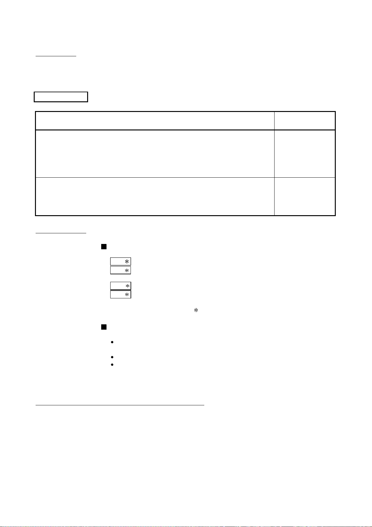
Punch press (X, Y feed positioning
Gear and ball screw
Conveyor control
Servomotor
(with brakes)
Servo amplifier
Teaching unit
AD75TU
Press head
Servo
amplifier
Reduction
gears
Y axis
X axis
servomotor
G
Ball screw
(From QD75)
AD75
Servo
mplifier
Palletizer
Y axis
servomotor
)
X axis
Conveyor
320mm
Y axis
X axis
Gear and rack & pinion
PLC
MELSEC-Q
160mm
Press
punching
12 s
PLC
MELSEC-Q
X axis
Y axis
Position detector
Palletizer
Unloader control
QD75
15m/min
(2000r/min
15m/min
(1875r/min)
QD75
AD75
•
To punch insulation material or leather, etc.,
as the same shape at a high yield, positioning
is carried out with the X axis and Y axis
servos.
•
After positioning the table with the X axis
servo, the press head is positioned with the Y
axis servo, and is then punched with the
press.
•
When the material type or shape changes, the
press head die is changed, and the positioning
pattern is changed.
•
Using the servo for one axis, the palletizer is
positioned at a high accuracy.
•
The amount to lower the palletizer according to
the material thickness is saved.
Compact machining center (ATC magazine positioning)
•
The ATC tool magazine for a compact
machining center is positioned.
•
The relation of the magazine's current value
and target value is calculated, and positioning
is carried out with forward run or reverse run to
achieve the shortest access time.
Servo
amplifier
QD75
AD75
Servomotor
Coupling
Positioning
pin
PLC
MELSEC-Q
Reduction
gears
ATC tool
magazine
Tool
(12 pcs., 20 pcs.)
Rotatio n di r e c t io n
for calling
11, 12, 1, 2 or 3
Current
value
retrieval
position
Rotation direction
for calling 5, 6, 7, 8, 9 or 10
<No. of tools: 12> <No. of tools: 20>
Rotatio n di r e c t io n
for calling
17 to 20, 1 to 5
Rotatio n di r e c t io n
for calling 7 to 16
Current
value
retrieval
position
1 - 5
Page 26
1 PRODUCT OUTLINE
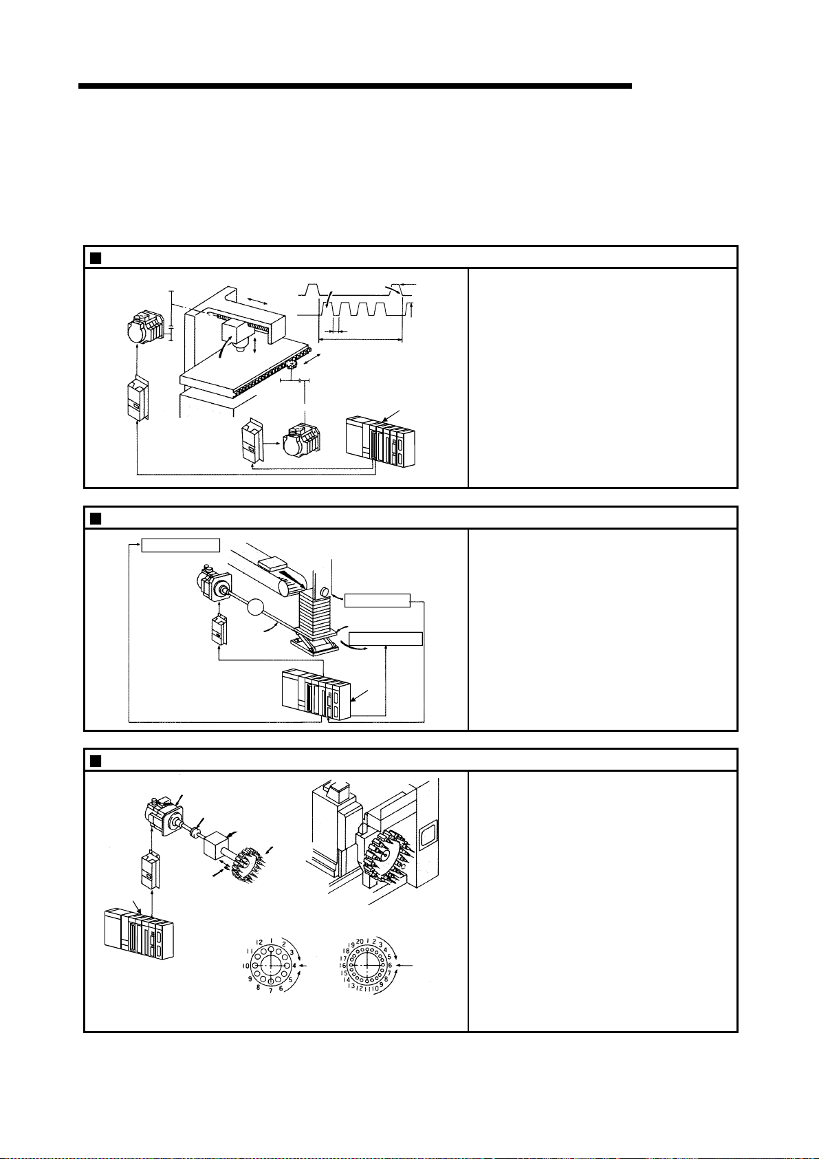
Lifter (Sto rage o f Br au n tub e s on to aging rack)
B conveyor
Lifter C
Counterweight
Reduction
gears
G1
Servomotor
(with brakes)
Index table (High-accuracy indexing of angle)
PLC
MELSEC-Q
conveyor
A conveyor Servo amplifier
Loader
Servomotor
Servo amplifier
Aging rack
G2
Positioni n g modu le
QD75
AD75
QD75
Unloader
Loader/unloader
PLC MELSEC-Q
MELSEC-Q
•
During the aging process of braun tubes,
storage onto the rack is carried out by
positioning with the AC servo.
•
The up/down positioning of the lifter is carried
out with the 1-axis servo, and the horizontal
position of the aging rack is positioned with the
2-axis servo.
•
The index table is positioned at a high accuracy
using the 1-axis servo.
Digital switch
Index table
Worm gears
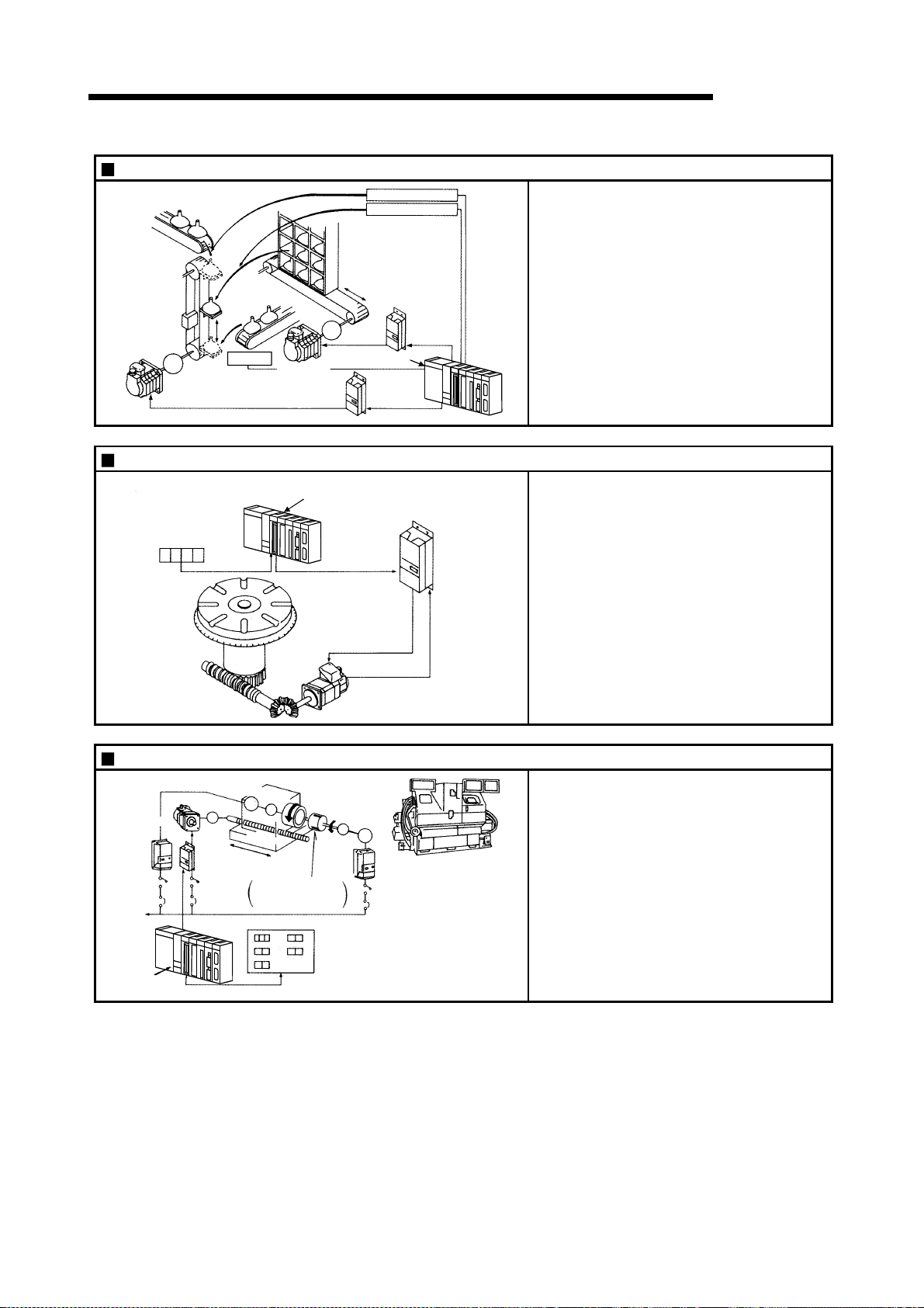
Inner surface grinder
Servomotor
Inverter
Servo
amplifier
220VAC
60Hz
QD75
PLC
MELSEC-Q
Motor
1M
G
Fix the grinding
stone, feed the
workpiece, and grind.
Operation panel
a
b
c
Workpiece
Grinding stone
a. Total feed
amount (mm)
d
b. Finishing
e
feed amount (mm)
c. Compensation
amount (mm)
Detector
Servomotor
Motor
G
1M
Inverter
Servo
amplifier
d. Rough grind ing speed (mm/s)
e. Fine grindi ng
speed (mm/s)
•
The grinding of the workpiece's inner surface
is controlled with the servo and inverter.
•
The rotation of the workpiece is controlled with
the 1-axis inverter, and the rotation of the
grinding stone is controlled with the 2-axis
inverter. The workpiece is fed and ground with
the 3-axis servo.
1 - 6
Page 27
1 PRODUCT OUTLINE
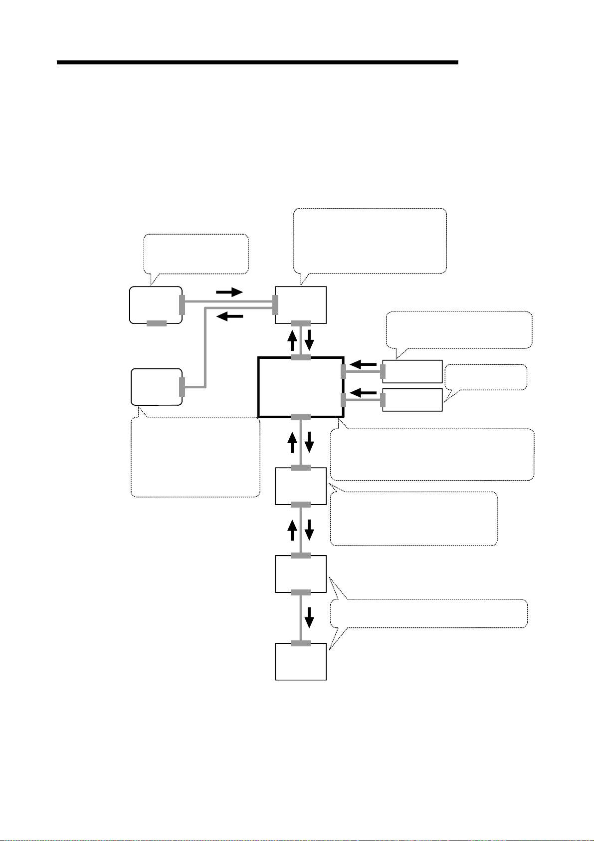
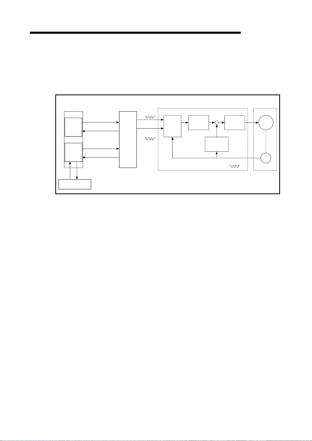
1.1.3 Mechanism of positioning control
Positioning control using the QD75 is carried out with "pulse signals". (The QD75 is a
module that generates pulses). In the positioning system using the QD75, various
software and devices are used for the following roles. The QD75 realizes complicated
positioning control when it reads in various signals, parameters and data and is
controlled with the PLC CPU.
MELSEC-Q
Creates control order and
conditions as a sequence
program.
GX Developer
GX
Configurator
-QP
Sets the parameters and
positioning data for control.
Outputs the start command for
JOG operation, etc., during test
operation with the test mode.
Monitors the positioning operation.
PLC CPU
QD75 positioning
module
Servo
amplifier
Stores t he creat e d program.
The QD75 outputs the start signal and
stop signal following the stored program.
QD75 errors, etc., are detected.
Outputs signals such as the start
signal, stop signal, limit signal and
control changeover signal to the QD75.
External signal
Stores the parameter and data.
Outputs pulses to the servo according to the
instructions from the PLC CPU, GX Configurator-QP,
external signals and manual pulse generator.
Manual pulse
generator
Receives pulse commands from QD75, and
drives the motor.
Outputs the drive unit READY signal and
zero signal to the QD75.
Issues commands by
transmitting pulses.
Motor
Workpiece
1 - 7
Carries out the actual work according to commands
from the servo.
Page 28
1 PRODUCT OUTLINE
A
The principle of "position control" and "speed control" operation is shown below.
Position control
The total No. of pulses required to move the designated distance is obtained in the
following manner.
MELSEC-Q
Positioning
module
Total No. of pulses
required to move
designated distance
The No. of pulses required for the motor to rotate once is the "encoder resolution"
described in the motor catalog specification list.
=
Movement amount of machine (load)
side when motor rotates once
Designated distance
No. of pulses
required for motor to
rotate once
When this total No. of pulses is issued from the QD75 to the servo amplifier, control to
move the designated distance can be executed.
The machine side movement amount when one pulse is issued to the servo amplifier is
called the "movement amount per pulse". This value is the min. value for the workpiece
to move, and is also the electrical positioning precision.
Speed control
The "Total No. of pulses" mentioned above is invariably required for controlling the
distance. For positioning or speed control, the speed must be controlled as well.
The speed is determined by the frequency of pulses sent from the QD75 to the drive
unit.
Servo
amplifier
Servo
motor
Detector
(Pulse
encoder)
Pulse frequency
[pps]
This area is the total
No. of commanded
pulses.
Speed = Pulses frequency
Movement amount = No.of pulses
Feedback pulses =
Pulses generated by detector
Fig. 1.1 Relationship between position control and speed control
POINT
The QD75 controls the position with the "total No. of pulses", and the speed with
the "pulse frequency".
Feedback pulses
ta td (s)
0.4 1.2 0.4
Movement amount t = 2
1 - 8
Page 29
1 PRODUCT OUTLINE
1.1.4 Outline design of positioning system
The outline of the positioning system operation and design, using the QD75, is shown
below.
(1) Positioning system using QD75
MELSEC-Q
PLC CPU
Program
Peripheral
devices
interface
Read, write, etc.
GX Configurator-QP
Fig. 1.2 Outline of the operation of positioning system using QD75
Forward run
pulse train
Reverse run
pulse train
Deviation
counter
Read, write, etc.
Read, write, etc.
Positioning module
QD75
Setting data
(a) Positioning operation by the QD75
1) The QD75 output is a pulse train.
The pulse train output by the QD75 is counted by and stored in the
deviation counter in the drive unit.
The D/A conve rte r out pu ts an an alog DC current pr op o rti on at e t o th e
count maintained by the deviation counter (called "pulse droop"). The
analog DC current serves as the servomotor speed control signal.
2) The motor rotation is controlled by the speed control signal from the
drive unit.
As the motor rotates, the pulse encoder (PLG) attached to the motor
generates feedback pulses, the frequency of which is proportionate to
the rotati on spee d.
The feedback pulses are fed back to the drive unit and decrements the
pulse droop, the pulse count maintained by the deviation counter.
The motor keeps on rotating as the pulse droop is maintained at a
certain level.
3) When the QD75 terminates the output of a pulse train, the motor
decelerates as the pulse droop decreases and stops when the count
drops to zero.
Thus, the motor rotation speed is proportionate to the pulse frequency,
while the overall motor rotation angle is proportionate to the total
number of pulses output by the QD75.
Therefore, when a movement amount per pulse is given, the overall
movement amount can be determined by the number of pulses in the
pulse train.
The pulse frequency, on the other hand, determines the motor rotation
speed (feed speed).
Drive unit
D/A
converter
Speed
command
Interface
Feedback pulse
Servo
amplifier
Servomotor
M
PLG
1 - 9
Page 30

1 PRODUCT OUTLINE
MELSEC-Q
(b) Pulse train output from the QD75
1) As shown in Fig. 1.3, the pulse frequency increases as the motor
accelerates. The pulses are sparse when the motor starts and more
frequent when the motor speed comes close to the target speed.
2) The pulse frequency stab iliz e s when t he mot o r spee d equ al s the targe t
speed.
3) The QD75 decreases the pulse frequency (sparser pulses) to
decelerate the motor before it finally stops the output.
There will be a little difference in timing between the decrease in the
pulse frequency and the actual deceleration and stopping of the motor.
This difference, called "the stop settling time", is required for gaining a
stopping accuracy.
Servomotor
Speed V
Pulse droop
amount
Pulse
distribution
speed
Pulse encoder
(PLG)
Servomotor
Acceleration
Pulse train Rough Dense Rough
Deceleration
Time t
Stop
settling time
Fig. 1.3 QD75 output pulses
(2) Movement amount and speed in a sy stem using w or m gear s
A : Movement amount per pulse (mm/pulse)
V
Workpiece
Table
P0
Worm gear
L
R
Fig. 1.4 System using worm gears
Vs : Command pulse frequency (pulse/s)
n : Pulse encoder resolution (pulse/rev)
L : Worm gear lead (mm/rev)
R : Deceleration ratio
V : Movable section speed (mm/s)
N : Motor speed (r/min)
K : Position loop gain (1/s)
P
: D ev iation co unter droo p pulse amount
ε
P0 : OP (pulse)
P : Address (pulse)
1 - 10
Page 31

1 PRODUCT OUTLINE
MELSEC-Q
(a) In the system shown in Fig. 1.4, the movement amount per pulse,
command pulse frequency, and the deviation counter droop pulser amount
are determined as follows:
1) Movement amount per pulse
The movement amount per pulse is determined by the worm gear lead,
deceleration ratio, and the pulse encoder resolution.
The movement amount, therefore, is given as follows: (Number of
pulses output) × (Movement amount per pulse).
A =
2) Command pulse frequency
The command pulse frequency is determined by the speed of the
moving part and movement amount per pulse:
Vs =
3) Deviation counter droop pulser amount.
The deviation counter droop pulser amount is determined by the
command pulse frequency and position loop gain.
=
ε
L
R × n
V
A
Vs
K
[mm/pulse]
[pulse/s]
[pulse]
(b) The QD75 allows the user to select from the following four units as the unit
used by positioning commands to any of the axes (1 to 4, if the module
supports four axes): mm, inch, degree, and pulse.
The unit selected for one axis may differ from the unit selected for another
axis.
When such data as the movement amount per pulse,
acceleration/deceleration time, positioning speed, and positioning address
are correctly set in consideration of the chosen unit, the QD75 can calculate
the number of pulses required for a movement amount to the target
positioning address and execute the positioning by outputting a pulse train
that includes the calculated number of pulses.
1 - 11
Page 32

1 PRODUCT OUTLINE
1.1.5 Communicating signals betw een QD 75 and each mo dul e
The outline of the signal communication between the QD75 and PLC CPU, peripheral
device and drive unit, etc., is shown below.
(A peripheral device communicates with the QD75 via the PLC CPU to which it is
connected)
PLC
CPU
Y0
X0
X1
Y8,YA,YC,YE
Y9,YB,YD,YF
Y14,Y15,Y16,Y17
PLC READY signal
QD75 READY s ignal
Syncronization flag
Forward run JOG start signal
Reverse run JOG start signal
Execution prohibition flag
QD75
External
interface
MELSEC-Q
Drive unit READY signal
Upper/lower limit signal
Near-point dog signal
Zero signal
Deviation counter clear
Pulse train
External
signal
Drive
unit
Y10,Y11,Y12,Y13
X14,X15,X16,X17
XC,XD,XE,XF
X10,X11,X12,X13
Y4,Y5,Y6,Y7
X4,X5,X6,X7
X8,X9,XA,XB
Peripheral
device
interface
Positioning start signal
Positioning complete signal
BUSY signal
Start complete signal
Axis stop signal
M code ON signal
Error detection signal
Data write/read
Parameter write/read
Positioning data write/read
Block start data write/read
OPR operation (test)
JOG/Inching operation
Positioning operation (test)
Interface
with
PLC
CPU
Manual pulse generator A-phase
Manual pulse generator B-phase
Stop signal
External command signal
Manual pulse
generator
External
signal
Peripheral
device
Operation monitor
1 - 12
Page 33

1 PRODUCT OUTLINE
QD75 PLC CPU
The QD75 and PLC CPU communicate the following data via the base unit.
MELSEC-Q
Communication
Control signal
Data (read/write)
Direction
Signal indicating QD75 state, such as
QD75 READY signal, BUSY signal.
• Parameter
• Positioning data
• Block start data
• Control data
• Monitor data
QD75
PLC CPU PLC CPU QD75
Signal related to commands such as PLC
READY signal, various start signals, stop
signals
• Parameter
• Positioning data
• Block start data
• Control data
Refer to Section 3.3 "Specifications of input/output signals with PLC CPU" for details.
QD75 Peripheral device
The QD75 and peripheral device communicate the following data via the PLC CPU:
Direction
Communication
Data (read/write)
Test operation –
Operation monitor • Monitor data –
QD75
• Parameter
• Positioning data
• Block start data
Peripheral device Peripheral device QD75
• Parameter
• Positioning data
• Block start data
• OPR control start command
• Positioning control start command
• JOG/Inching operation start command
• Teaching start command
• Manual pulse generator operation
enable/disable command
QD75 Drive unit
The QD75 and drive unit communicate the following data via the external device
connection connector.
Direction
Communication
Control signal
Pulse train • Pulse train output –
Signals related to commands such as
deviation counter clear signal
QD75
Drive unit Drive unit QD75
Signals indicating drive unit state such as
drive unit READY signal
QD75 Manual pulse generator
The QD75 and manual pulse generator communicate the following data via the
external device connection connector.
(The manual pulse generator should be connected to an external device connection
connector for axis 1 or for axes 1 and 2.)
Direction
Communication
Pulse signal –
QD75
Manual pulse generator Manual pulse generator QD75
Manual pulse generator A-phase, manual
pulse generator B-phase
1 - 13
Page 34

1 PRODUCT OUTLINE
QD75 External signa l
The QD75 and external signal communicate the following data via the external
device connection connector.
MELSEC-Q
Direction
Communication
Control signal –
QD75
External signal External signal QD75
•
Signals from detector such as near-point
dog signal, upper/lower limit signal, zero
signal
•
Control signals from external device such
as stop signal, external command signal
1 - 14
Page 35

1 PRODUCT OUTLINE
1.2 Flow of system operation
1.2.1 Flow of all processes
The positioning control processes, using the QD75, are shown below.
MELSEC-Q
Design
Preparation
GX Configurator-QP
1)
Understand the functions and performance, and determine the positioning oper at ion method
(system design)
3) 4)
Settin g of the:
· Parameters
· Positioning data
· Block start data
· Condition data
Writing of setting data
QD75
2)
Installation, wiring
Servo, etc.
5) 6)
PLC CPU
Creation of sequence
program for operation
Refer to (N o te)
GX Developer
Writing of program
Operation
Maintenance
7) 8)
Monitoring with
test operation,
and debugging
of setting data
Monitor
9)
10)
11)
Connection confirmation
Test operation
Actual operation
Maintenance
Disposal
(Note)
When not using
GX Configurator
-QP, carry out
setting, monitoring
and debugging of
the data in 3) with
GX Developer.
Monitoring and
debugging of
operation
program
Monitor
1 - 15
Page 36

1 PRODUCT OUTLINE
The following work is carried out with the processes shown on the previous page.
Details Reference
Understand the product functions and usage methods, the configurati on dev ices
1)
and specifications required for positioning control, and des ign the sy stem.
Install the QD75 onto the base unit, wire the QD75 and external connection d ev ices
2)
(drive unit, etc.).
Using GX Configurator-QP, set the parameters, positioning data, block start data
3)
and condition data required for the positioning control to be ex ecuted.
Using GX Developer, create the sequence program required for positioning
4)
operation. (When not using GX Configurator-QP, also create the sequence program
for setting data.)
Write the parameters and positioning data, etc., created w ith GX Configurator-Q P
5)
into the QD75.
Using GX Developer, write the created sequence program into the PLC C PU.
6)
(When not using GX Configurator-QP, also write in the sequence program for
setting data.)
Carry out test operation and adjustments in the test mode to check th e conne ction
with the QD75 and external connection device, and to confirm that the d esignated
7)
positioning operation is executed correctly. (Debug the set "para meters" and
"positioning data", etc.)
Carry out test operation and adjustment to confirm that the designated positioning
8)
operation is executed correctly. (Debug the created sequence program. When not
using GX Configurator-QP, also debug the set data.
Actually operate the positioning operation. At this time, monitor the operation state
9)
as required. If an error or warning occurs, remedy.
10) Service the QD75 as required.
11) Dispose of the QD75.
MELSEC-Q
•
Chapter 1
•
Chapter 2
•
Chapter 3
•
Chapter 8 to Chapter 13
•
Chapter 4
•
Chapter 5
•
Chapter 8 to Chapter 13
•
GX Configurator-QP
Operating Manual
•
Chapter 6
•
GX Developer Operating
Manual
•
Chapter 7
•
GX Configurator-QP
Operating Manual
•
Chapter 7
•
GX Developer Operating
Manual
•
GX Configurator-QP
Operating Manual
•
Chapter 13
•
GX Developer Operating
Manual
•
GX Developer Operating
Manual
•
Chapter 5
•
Chapter 15
•
GX Configurator-QP
Operating Manual
•
GX Developer Operating
Manual
•
Chapter 4
•
Chapter 4
1 - 16
Page 37

1 PRODUCT OUTLINE
MEMO
MELSEC-Q
1 - 17
Page 38

1 PRODUCT OUTLINE
1.2.2 Outline of starting
The outline for starting each control is shown with the following flowchart.
It is assumed that each module is installed, and the required system configuration,
etc., has been prepared.
MELSEC-Q
Preparation
Control
functions
Positioning
parameters
OPR parameters
Positioning
data
Block start data
Control data
Start signal
Flow of starting
Installation and connection of module
Setting of hardware
Major positioning control
·Position contro l
·Speed control
·Speed-position
switching control
·Position-speed
switching control
·Other control
Set the positioning data.
)
Set the positioning start No.
Da.1)Da.10
High-level positioning
control
·Block start (Normal start)
·Condition start
·Wait start
·Simultaneous start
·Repeated start
Set the positioning parameters.
to
Set the block start
data.
)
to
Da.11)Da.19
Set the positioning
starting point No.
Input the start signal.
Method (1) Turn ON the QD75 start sig nal from the
PLC CPU
Method (2) Issue the PSTRT instruct i on from the PLC CPU.
Method (3) Turn the QD75 external st art signal ON
)
Cd.4
)
OPR control Manual control
·Machine OPR control
·Fast OPR control
Set the OPR parameters.
)
Pr.43
)
)
Cd.3
·JOG operation
)
Pr.1 Pr.42
)
to
Pr.57
Set the JOG speed
)
to ,
Cd.17
·Inching operation
Pr.150
)
·Manual pulse generator operation
)
Set the manual pulse
generator enable flag to "1".
Set the inching
movement amount
to other than 0.
)
)
Cd.16
Set the inching
movement
amount to 0.
)
)
Cd.16
Turn the QD75 JOG start signal
ON from the PLC CPU
Set the manual pulse generator
1 pulse input magnification.
Operate the
manual pulse
generator
)
Cd.21
)
Cd.20
)
)
Control start
Control end
Operation
Stop
1 - 18
Page 39

1 PRODUCT OUTLINE
MELSEC-Q
Setting method
<GX Configurator-QP>
Set with GX Configurator-QP
Set the parameter and data for executing main function,
and the sub functions that need to be set beforehand.
<GX Developer>
Create sequence program
for setting data
When set with "GX Configurator-QP",
this does not need to be created.
Write
<GX Developer>
Create sequence program for
executing main function
Create sequence program for
outputting control signals, such
as start signal, to QD75.
Operation sequence program PLC CPU
: Indicates the se quence program that must be created.
QD75
Write
PLC CPU Write
Write
<GX Developer>
· Speed change
· Current value changing
· Torque limit
· Restart, etc.
Create a sequence
program for the
sub functions.
1 - 19
Page 40

1 PRODUCT OUTLINE
1.2.3 Outline of stopping
Each control is stop pe d in the fo ll ow in g ca ses.
(1) When each control is completed normally.
(2) When the drive unit READY signal is turned OFF.
(3) When a PLC CPU error occurs
(4) When the PLC READY signal is turned OFF.
(5) When an error occurs in the QD75.
(6) When control is intentionally stopped (Stop signal from PLC CPU turned ON, stop
The outline for the stopping process in these cases is shown below. (Excluding (1) for
normal stopping.)
MELSEC-Q
signal from an external device, etc.)
Stop cause
Forced stop
Fatal stop
(Stop group 1)
Emergency
stop
(Stop group 2)
Relatively safe
stop
(Stop group 3)
Intentional stop
(Stop group 3)
Drive unit
READY
signal OFF
Hardware
stroke limit
upper/lower
limit error
occurrence
PLC CPU
error
occurrence
PLC READY
signal OFF
Error in test
mode
Axis error
detection
(Error other
than stop
group 1 or 2)
“Stop signal”
from
peripheral
device
"Stop signal"
ON from
external
source
"Axis stop
signal" ON
from PLC
CPU
M code
Stop
ON signal
axis
after stop
Each
axisNochange
Each
axisNochange
No
change
All
Turns
axes
OFF
No
change
Each
axisNochange
Each
axisNochange
Axis
operation
status
after
stopping
Md.26
(
During
error
During
error
During
error
During
error
When
stopped
(While
waiting)
Stop process
OPR control Manual control
Machine
OPR
)
control
control
Immediate stop
Deceleration stop/sudden stop
(Select with “
sudden stop selection” )
Deceleration stop/sudden stop
(Select with “
sudden stop selection” )
Deceleration stop/sudden stop
(Select with “
sudden stop selection”)
Major
Fast
positioning
OPR
control
Pr.37
Pr.38
Pr.39 Sudden stop group3
High-level
positioning
control
Sudden stop group1
Sudden stop group2
JOG/
Inching
operation
Manual
pulse
generator
operation
Deceleration
stop
Deceleration
stop
Deceleration
stop
Deceleration
stop
1 - 20
Page 41

1 PRODUCT OUTLINE
4
4
1.2.4 Outline for restarting
When a stop cause has occurred during operation with position control causing the
axis to stop, positioning to the end point of the positioning data can be restarted from
the stopped posit io n by usin g th e "
If issued during a continuous positioning or continuous path control operation, the
restart command will cause the positioning to be re-executed using the
current position (pointed by the positioning data No. associated with the
moment when the movement was interrupted) as the start point.
Cd.6
Restart command".
MELSEC-Q
When "
(1) If the "
the positioning data will be restarted from the stopped position regardless of
the absolute system or incremental system.
(2) When "
possible" (warning code: 104) will be applied, and the restart command will be
ignored.
[Example for incremental system]
(a) The restart operation when the axis 1 movement amount is 300, and the
axis 2 movement amount is 600 is shown below.
Axis 1
Stop position due to stop cause
00
Start point
address
200
100
100 300 700
Reference
Cd.6
Restart command" is ON
Md.26
Axis operation status" is stopped, positioning to the end point of
Md.26
Axis operation status" is not stopped, the warning "Restart not
Designated end
point position
Axis 2
Restart
Axis 1
Stop position due to stop cause
400
200
100
100 300 700
Stop position
after restart
Operation during
restart
Axis 2
If the positioning start signal [Y10 to Y13]/external command signal is turned ON
while the "
restarted from the start of the positioning start data regardless of the absolute
system or incremental system. (
"External positioni ng star t ")
(Same as normal positioning.)
[Example for incremental system]
(a) The positioning start operation when the axis 1 movement amount is 300
Axis 1
Stop position due to stop cause
00
Start po int
address
200
100
100 300 700
Md.26
Axis operation status" is waiting or stopped, positioning will be
: When the external command signal is set to
and the axis 2 movement amount is 600 is shown below.
Axis 1
Stop position due to stop cause
500
Axis 2
Positioning
start
200
100
100 300 900
Designated end
point position
1 - 21
Stop position
after restart
Operation during
positioning start
Axis 2
Page 42
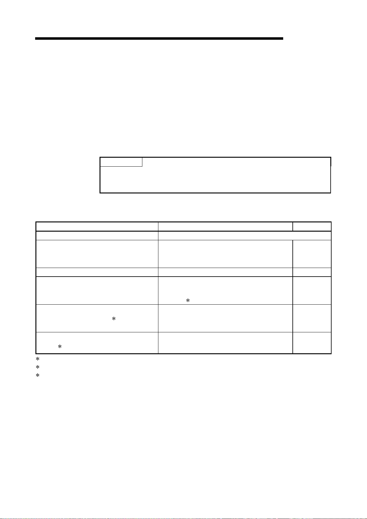
1 PRODUCT OUTLINE
1.3 Restrictions with a system using a stepping motor
Note the following restrictions applicable to a system that uses a stepping motor:
(1) The S-pattern acceleration/deceleration is disabled because it requires a
servomotor for the controlled axis.
(2) The circular interpolation control is disabled because it requires a servomotor
for each of the two controlled axes.
1.4 Function additions/modifications according to function v er si on B
POINT
When it is desired to check the following items, refer to the corresponding
explanation sections.
How to check the function version and SERIAL No. (Refer to Section 2.4)
The following function additions/modifications according to the function version B of the
QD75:
MELSEC-Q
Function Outline Reference
Multiple PLC compatible function Refer to QCPU User's Manual (Multiple CPU System).
Function which starts the axis under speed control,
Speed-position switching control (ABS mode)
Pre-reading start function Function which shortens virtual start time. Section 12.7.8
External I/O signal monitor function
Deceleration start flag function 2
Stop command processing for deceleration stop
function 3
1: Usable on GX Developer (SW6D5C-GPPW-E or later). For details, refer to GX Developer Operating Manual.
2: Usable with the module whose first five digits of SERIAL No. are "03042" or later.
3: Usable with the module whose first five digits of SERIAL No. are "05072" or later.
switches to position control at the external command
signal input, then positions the axis to a stop at the
designated address.
Function which monitors the external I/O signal monitor
information in the module's detailed information w hich
can be displayed on the system monitor of GX
Developer
Function that turns ON the flag when the constant
speed status or acceleration status switches to the
deceleration status during position control w hose
operation pattern is "Positioning complete".
Function that selects a deceleration curve when a stop
cause occurs during deceleration stop processing to
speed 0.
1.
Section 9.2.17
Section 13.5
Section 12.7.9
Section 12.7.10
1 - 22
Page 43

Chapter 2 System Configuration
In this chapter, the general image of the system configuration of the positioning control
using QD75, the configuration devices, applicable CPU and the precautions of configuring
the system are expla ine d.
Prepare the required configuration devices to match the positioning control system.
2
2.1 General image of system.............................................................................................2- 2
2.2 Component list..............................................................................................................2- 4
2.3 Applicable system.........................................................................................................2- 5
2.4 How to check the function version and SERIAL No....................................................2- 6
2 - 1
Page 44
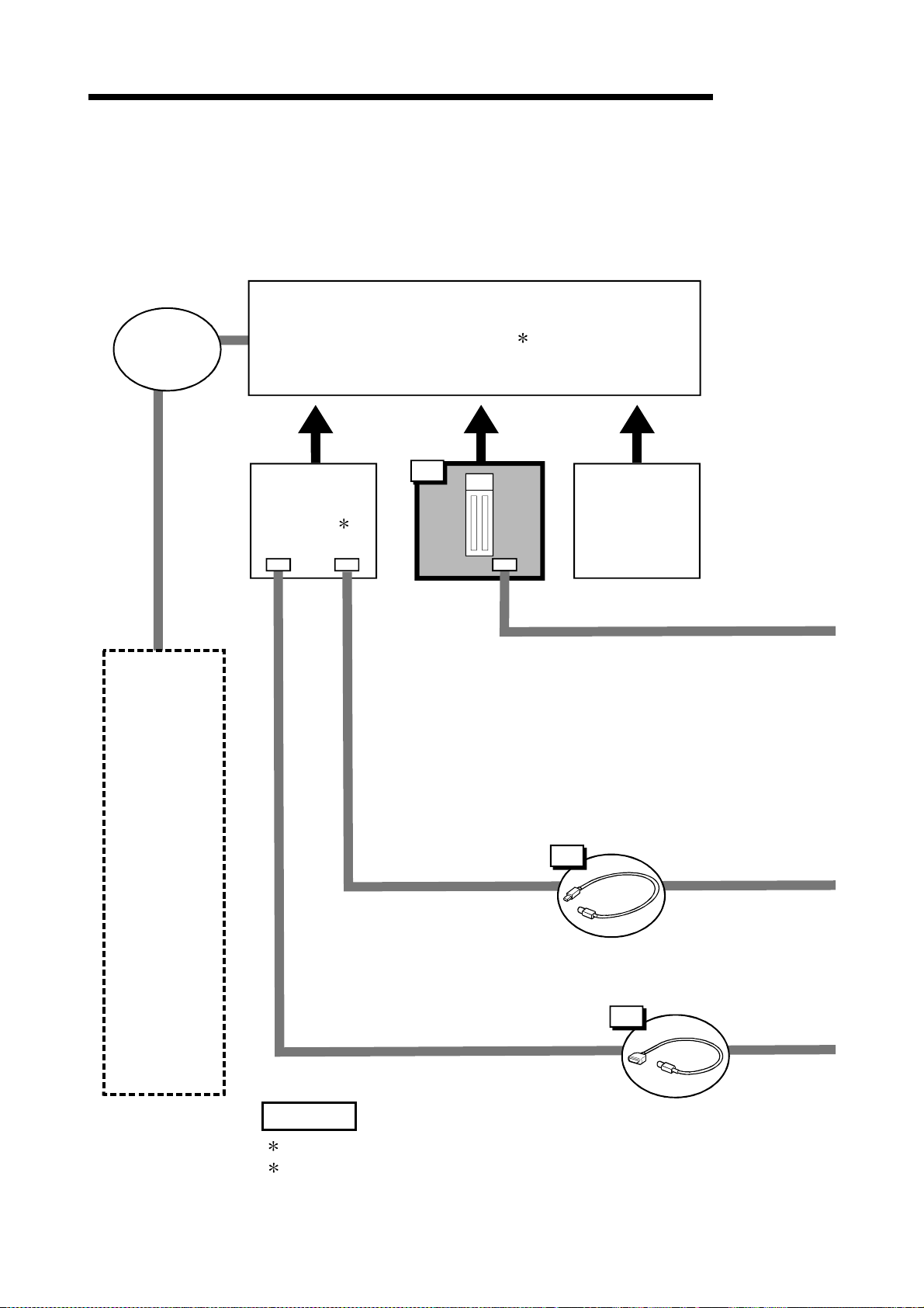
2 SYSTEM CONFIGURATION
2.1 General image of system
The general image of the system, including the QD75, PLC CPU and peripheral
devices is shown below .
(The Nos. in the illustration refer to the "No." in Section 2.2 "Component list".
MELSEC-Q
Extension
cable
CPU
module 1
Main base unit 2
Positioning
module
1
I/O
module
Extension
system
USB cable
5
RS-232 cable
4
REMARK
1 Refer to Section 2.3 "Applicable system" for the CPU modules that can be used.
2 Refer to the CPU module User's Manual for the base units that can be used.
2 - 2
Page 45

2 SYSTEM CONFIGURATION
g
MELSEC-Q
6
Drive
unit
Motor
Manual pulse generator
7
Cable
Machine system inputs (switches)
8
Near point dog
Limit switch
External command
signal
Stop signal
Peripheral device
Personal
computer
GX Configurator
-QP
3
2
SWnD5C
-QD75P-E
(For details, refer to GX Configurator
-QP Operatin
Manual.)
2 - 3
Page 46

2 SYSTEM CONFIGURATION
2.2 Component list
The positioning system using the QD75 is configured of the following devices.
No. Part name Type Remarks
QD75P1
QD75P2
1 Positioning module
2 GX Configurator-QP
3 Personal computer
4 RS-232 cable QC30R2
5 USB cable –
6 Drive unit – (Prepared by user)
Manual pulse
7
generator
Connection cable
(For connecting
8
between the QD75
and the drive unit)
QD75P4
QD75D1
QD75D2
QD75D4
D5C-
SW
QD75P-E
DOS/V personal
computer
–
–
QD75
No. of control axes
P: Open collector output system
Refer to GX Configurator-QP Operating Manual for details.
(Prepared by user)
Refer to GX Configurator-QP Operating Manual for details.
(Prepared by user)
An RS-232 cable is needed for connecting the CPU module w ith a
personal computer (DOS/V).
For details, refer to GX Configurator-QP Operating Manual.
(Prepared by user)
A USB cable is needed for connecting the CPU module with a personal
computer (DOS/V).
For details, refer to GX Configurator-QP Operating Manual.
(Prepared by user)
Recommended: MR-HDP01 (Mitsubishi Electric)
(Prepared by user)
Cables are needed to connect the QD75 with the driv e unit, manual pulse
generator, and input devices in the machine system.
(Prepare them referring to the manuals for the connected devices and
information given in 3.4.2 of this manual.)
D: Differential driver output system
MELSEC-Q
Specifications of recommended manual pulse generator
Item Specifications
Model name MR-HDP01
Pulse resolution 25pulse/rev (100 pulse/rev after mag nification by 4)
2 - 4
Voltage-output (power supply voltage -1V or more),
Output current
Radial load: Max. 19.6N
Thrust load: Max. 9.8N
Max. 20mA
Output method
Power supply voltage 4.5 to 13.2VDC
Current consumption 60mA
Life time 100 revolutions (at 200r/min)
Permitted axial loads
Operation temperature -10 to 60 (14 to 140 )
Weight 0.4 (0.88) [kg(lb)]
Number of max. revolution Instantaneous Max. 600r/min. normal 200r/min
Pulse signal status 2 signals: A phase, B phase, 90 phase difference
Friction torque 0.1N/m (at 20 (68 ))
Page 47

2 SYSTEM CONFIGURATION
2.3 Applicable system
The QD75 can be used in the following system.
(1) Applicable modules and the num ber of installable modules
The following table indicates the CPU modules and network modules (for remote
I/O station) usable with the QD75 and the number of installable modules.
Applicable modules Number of installable modules Remarks
CPU
module
Network
module
1 Refer to the User's Manual (Hardware Design, Maintenanse and Inspection) of the CP U
module used.
2 Refer to the Q Corresponding MELSECNET/H Network System Reference Manual
(Remote I/O Network).
Q00JCPU Max. 16 modules
Q00CPU
Q01CPU
Q02CPU
Q02HCPU
Q06HCPU
Q12HCPU
Q25HCPU
Q12PHCPU
Q25PHCPU
QJ72LP25-25
QJ72BR15
QJ72LP25G
QJ72LP25GE
Max. 24 modules
Max. 64 modules
Max. 64 modules
Max. 64 modules
MELSEC-Q
(
1)
Installable in the Q mode
only
1)
(
1)
(
MELSECNET/H remote I/O
station (
2)
(2) Usable base unit
The QD75 can be installed in any of the I/O slots (
When installing the QD75, always consider the power supply capacity since a
shortage of the power supply capacity may occur depending on the combination
with the other installed module and the number of installed module.
3 Within the I/O point range of the CPU module and network module (for remote
I/O station).
) of a base unit.
3
(3) Compatibility with multiple PLC system
When using the QD75 in a multiple PLC system, first refer to the QCPU (Q mode)
User's Manual (Function Explanation, Program Fundamentals).
(4) Supported software packages
The following table lists the compatibility between the systems using the QD75 and
the software packages. GX Developer is required for use of the QD75.
Software version
GX Developer GX Configurator-QP
Single PLC
Q00J/Q00/Q01CPU
Q02/Q02H/Q06H/
Q12H/Q25HCPU
Q12PH/Q25PHCPU
For use on MELSECNET/H remote
I/O station
system
Multiple PLC
system
Single PLC
system
Multiple PLC
system
Single PLC
system
Multiple PLC
system
Version 7 or more
Version 8 or more
Version 2.10L or more
Version 4 or more
Version 6 or more
Version 7.10L or more Version 2.13P or more
Version 6 or more Version 2.10L or more
2 - 5
Page 48

2 SYSTEM CONFIGURATION
2.4 How to check the function version and SERIAL No.
The function version and SERIAL No. of the QD75 can be checked in the following
methods.
[1] Method using the rated plate on the module side face
[2] Method using the software
[1] Method using the rated plate on the module si de fac e
Check the function version and SERIAL No. in the "SERIAL" field.
MELSEC-Q
SERIAL No. (The first five digits)
Function version
Standard symbol for conformance
is discribed
[2] Method using the software
Check the function version and SERIAL No. in "Product information" displayed
on System monitor "Module's Detailed Information" of GX Developer *1 or on
"OS information" of GX Configurator-QP *2.
<GX Developer display screen> <GX Configurator-Q P display screen>
SERIAL No.
Function version
1: This check can be made using the version of SW4D5C-GPPW-E or more. For details, refer
to GX Developer Ope rat in g Manu al .
2: For detail s, r e fe r to GX Con fi gu rat o r- QP Op er at in g Ma nual.
2 - 6
Page 49

Chapter 3 Specifications and Functions
The various specifications of the QD75 are explained in this chapter.
The "General specifications", "Performance specifications", "List of functions",
"Specifications of input/output signals with PLC CPU", and the "Specifications of
input/output interfaces with external devices", etc., are described as information required
when designing the positioning system.
Confirm each specificat ion before designing the positioning system.
3
3.1 Performance specifications..........................................................................................3- 2
3.2 List of functions ............................................................................................................3- 4
3.2.1 QD75 control functions...................................................................................3- 4
3.2.2 QD75 main functions......................................................................................3- 6
3.2.3 QD75 sub functions and common functions..................................................3- 8
3.2.4 Combination of QD75 main functions and sub functions .............................3- 12
3.3 Specifications of input/output signals with PLC CPU.................................................3- 14
3.3.1 List of input/output signals with PLC CPU ....................................................3- 14
3.3.2 De ta il s of in pu t sign al s (Q D75
3.3.3 Details of output signals (PLC CPU
3.4 Specifications of input/output interfaces with external devices..................................3- 17
3.4.1 Electrical specifications of input/output signals.............................................3- 17
3.4.2 Signal layout for external device connection connector ...............................3- 19
3.4.3 List of input/output signal details ...................................................................3- 20
3.4.4 Input/output interface internal circuit .............................................................3- 22
PLC CPU)................................................3- 15
QD75)..............................................3- 16
3 - 1
Page 50

3 SPECIFICATIONS AND FUNCTIONS
3.1 Performance specifications
MELSEC-Q
Model
Item
No. of control axes 1 axis 2 axes 4 axes
Interpolation function None
Control system
Control unit mm, inch, degree, pulse
Positioning data
Backup
Positioning system
Positioning range
Positioning
Speed command
Acceleration/
deceleration process
Acceleration/
deceleration time
Sudden stop
deceleration time
1: QD75P represents the open collector output system, and QD75D represents the differential driver output system.
2: In speed-position switching control (ABS mode), the control unit available is "degree" only. (For details, refer to Section 9.2.17 "Speed-
position switching control (ABS mode)".
PTP (Point To Point) control, path control (both linear and arc can be set), speed control, speedposition switching control, position-speed switching control
600 data (positioning data Nos. 1 to 600)/axis
(Can be set with peripheral device or sequence program.)
Parameters, positioning data, and block start data can be saved on flash ROM
(battery-less backup)
PTP control: Incremental system/absolute system
Speed-position switching control: Incremental system/absolute system
Position-speed switching control: Incremental system
Path control: Incremental system/absolute system
In absolute system
• –214748364.8 to 214748364.7 (µm)
• –21474.83648 to 21474.83647 (inch)
• 0 to 359.99999 (degree)
• –2147483648 to 2147483647 (pulse)
In incremental system
• –214748364.8 to 214748364.7 (µm)
• –21474.83648 to 21474.83647 (inch)
• –21474.83648 to 21474.83647 (degree)
• –2147483648 to 2147483647 (pulse)
In speed-position switching control (INC mode) / position-speed switching control
• 0 to 214748364.7 (µm)
• 0 to 21474.83647 (inch)
• 0 to 21474.83647 (degree)
• 0 to 2147483647 (pulse)
In speed-position switching control (ABS mode)
• 0 to 359.99999 (degree)
0.01 to 20000000.00 (mm/min)
0.001 to 2000000.000 (inch/min)
0.001 to 2000000.000 (degree/min)
1 to 1000000 (pulse/s)
Automatic trapezoidal acceleration/deceleration, S-pattern acceleration/deceleration
1 to 8388608 (ms)
Four patterns can be set for each of acceleration time and deceleration time
1 to 8388608 (ms)
QD75P1 1
QD75D1
QD75P2 1
QD75D2
2-axis linear interpolation
2-axis circular interpolation
QD75P4 1
QD75D4
2-, 3-, or 4-axis linear
interpolation
2-axis circular interpolation
2
3 - 2
Page 51

3 SPECIFICATIONS AND FUNCTIONS
×
MELSEC-Q
Item
Starting time (ms) 3
External wiring connection system 40-pin connector
Applicable wire size
Applicable connector for external
device
Max. output pulse
Max. connection distance between
servos
Internal current consumption
(5VDC)
Flash ROM write count Max. 100000 times
No. of occupied I/O points 32 points (I/O assignment: 32 points for intelligent function module)
Outline dimensions
Weight 0.15 kg 0.15 kg 0.16 kg
1: QD75P represents the open collector output system, and QD75D represents the differential driver output system.
3: Using the "Pre-reading start function", the virtual start time can be shortened. (For details, refer to Section 12.7.8 "Pre-reading start
function".
Model
1-axis linear control 6
1-axis speed control 6
2-axis linear interpolation control (Composite speed) 7
2-axis linear interpolation control (Reference axis speed) 7
2-axis circular interpolation control 7
2-axis speed control 6
3-axis linear interpolation control (Composite speed) 7
3-axis linear interpolation control (Reference axis speed) 7
3-axis speed control 6
4-axis linear interpolation control 7
4-axis speed control 7
0.3 mm
A6CON1, A6CON2, A6CON4 (sold separately)
QD75P1, QD75P2, QD75P4 : 200kpps
QD75D1, QD75D2, QD75D4 : 1Mpps
QD75P1, QD75P2, QD75P4 : 2m
QD75D1, QD75D2, QD75D4 : 10m
98 (H)
QD75P1 1
QD75D1
2
(for A6CON1 or A6CON4), AWG #24 (for A6CON2)
QD75P1 : 0.40A
QD75D1 :0.52A
27.4 (W) × 90 (D) mm
QD75P2 1
QD75D2
QD75P2 : 0.46A
QD75D2 :0.56A
QD75P4 1
QD75D4
Factors in starting time extension
The following times will b e ad ded to
the starting time in the described
conditions:
• S-pattern acceleration/
deceleration is selected: 0.5
• Other axis is in
operation: 1.5
• During continuous
positioning control: 0.2
• During continuous path
control: 1.0
QD75P4 : 0.58A
QD75D4 :0.82A
Differential driver common terminal specifications(QD75D1, QD75D2,
QD75D4 only)
Applicable wire size 12AWG
Rated multiple wire
connection size
Screw tightening torque 0.5N • m
Solid wire: 0.2 to 0.8 mm2 2 pcs.
Stranded wire: 0.2 to 0.8 mm
2
2 pcs.
3 - 3
Page 52

3 SPECIFICATIONS AND FUNCTIONS
3.2 List of functions
3.2.1 QD75 control functions
The QD75 has several functions. In this manual, the QD75 functions are categorized
and explained as follows.
Main functions
(1) OPR control
"OPR control" is a function that established the start point for carrying out
positioning control, and carries out positioning toward that start point. This is
used to return a workpiece, located at a position other than the OP when the
power is turned ON or after positioning stop, to the OP. The "OPR control" is
preregistered in the QD75 as the "Positioning start data No. 9001 (Machine
OPR)", and "Positioning start data No. 9002 (Fast OPR). (Refer to Chapter 8
"OPR Control".)
(2) Major positioning control
This control is carried out using the "Positioning data" stored in the QD75.
Positioning control, such as position control and speed control, is executed by
setting the required items in this "positioning data" and starting that positioning
data. An "operation pattern" can be set in this "positioning data", and with this
whether to carry out control with continuous positioning data (ex.: positioning
data No. 1, No. 2, No. 3, ...) can be set. (Refer to Chapter 9 "Major Positioning
Control".)
(3) High-level positioning control
This control executes the "positioning data" stored in the QD75 using the
"block start data". The following types of applied positioning control can be
carried out.
•
Random blocks, handling several continuing positioning data items as
"blocks", can be executed in the designated order.
•
"Condition judgment" can be added to position control and speed control.
•
The operation of the designated positioning data No. that is set for multiple
axes can be started simultaneously. (Pulses are output simultaneously to
multiple servos.)
•
The designated positioning data can be executed repeatedly, etc.,
(Refer to Chapter 10 "High-level Positioning Control".)
(4) Manual control
By inputting a signal into the QD75 from an external source, the QD75 will
output a random pulse train and carry out control. Use this manual control to
move the workpiece to a random position (JOG operation), and to finely adjust
the positioning (inching operation, manual pulse generator operation), etc.
(Refer to Chapter 11 "Manual Control".)
MELSEC-Q
Sub functions
When executing the main functions, control compensation, limits and functions can
be added. (Refer to Chapter 12 "Control Sub Functions".)
Common functions
Common control using the QD75 for "parameter initialization" or "backup of
execution data" can be carried out. (Refer to Chapter 13 "Common Functions".)
3 - 4
Page 53

3 SPECIFICATIONS AND FUNCTIONS
MELSEC-Q
OPR control
[Positioning start No.]
[9001]
[9002]
Major positioning control
<Control system>
Position control
Speed control
Speed-position switching contro l
Position-speed switching control
Other control
·1-axis linear control
·2-, 3-, or 4-axis linear
interpolation control
·1-axis fixed-feed
control
·2-, 3-, or 4-axis fixed-feed
control
·2-axis circular interpolation
control
·1-axis linear control
·2-axis linear interpolation control
·3-axis linear interpolation control
·4-axis linear interpolation control
·Current value changing,
NOP instruction
·JUMP instruction,
LOOP to LEND
High-level positioning control
Major positioning
control
[Positioning start No.]
[9004]
Manual control
[Block start data]
[Positioning start signal]
JOG start signal ON
Pulse input from manual
pulse generator
Main functions
Control registered in QD75
Control using "Positioning data"
Machine OPR
Fast OPR
<Operation
pattern>
Independent
positioning control
(Positioning complete)
Continuous
positioning control
Continuous path
control
Control using "positioning data"
+ "Block start data"
Block start (Normal start)
Condition start
Wait start
Simultaneous start
Repeated start
(FOR loop)
Repeated start
(FOR condition)
Multiple axes
simultaneous start
control
Control with signals input from external source
JOG operation, Inching op er ation
Manual pulse generator
operation
Sub functions
(Functions characteristic to
machine OPR)
OPR
retry function
OP shift function
<Functions that compensate
control>
Backlash compensation function
Electronic gear function
Near pass function
<Functions that limit control>
Speed limit functi on
Torque limit function
Software stroke limit function
Hardware stroke limit function
<Functions that change
control details>
Speed change function
Override function
Acceleration/deceleration
time change function
Torque change function
<Absolute position restoration
function>
<Other functions>
Step function
Skip function
Continuous operation
interrupt function
M code output function
Teaching function
Target position change
function
Command in-position
function
Acceleration/deceleration
processing function
Pre-reading start function
Deceleration start flag
function
Stop command processing
for deceleration stop function
Common functions
Parameter initialization function Execution data backup function External I/O logic switching function
External I/O signal monitor function
3 - 5
Page 54

3 SPECIFICATIONS AND FUNCTIONS
3.2.2 QD75 main functions
The outline of the main functions for positioning control with the QD75 is described
below. (Refer to Section 2 for details on each function.)
Main functions Details
Machine OPR control
Fast OPR control
OPR control
Linear control
(1-axis linear control)
(2-axis linear interpolation control)
(3-axis linear interpolation control)
(4-axis linear interpolation control)
Position
control
Speed
control
Speed-position switching control
Major positioning control
Position-speed switching control
Other
control
Fixed-feed control
(1-axis fixed-feed control)
(2-axis fixed-feed control)
(3-axis fixed-feed control)
(4-axis fixed-feed control)
2-axis circular interpolation control
Linear control
(1-axis linear control)
(2-axis linear interpolation control)
(3-axis linear interpolation control)
(4-axis linear interpolation control)
Current value changing
NOP instruction
JUMP instruction
LOOP Carries out loop control with repeated LOOP to LEND. 9.2.22
LEND
MELSEC-Q
Mechanically establishes the positioning st art point us ing
a near-point dog or stopper. (Positioning start No. 9001)
Positions a target to the OP address (
feed value) stored in the QD75 using machine OPR.
(Positioning start No. 9002)
Positions a target using a linear path to the address set in
the positioning data or to the position designated with the
movement amount.
Positions a target by the movement amount designated
with the amount set in the positioning data.
(With fixed-feed control, the "
is set to "0" when the control is started. With
2-, 3-, or 4-axis fixed-feed control, the fixed-feed is fed
along a linear path obtained by interpolation.)
Positions a target using an arc path to the address set in
the positioning data, or to the position designated with the
movement amount, sub point or center point.
Continuously outputs the pulses corresponding to the
command speed set in the positioning data.
First, carries out speed control, and then carries out
position control (positioning with designated address or
movement amount) by turning the "speed-position
switching signal" ON.
First, carries out position control, and then carries out
speed control (continuous output of the pulses
corresponding to the designated command speed) by
turning the "position-speed switching signal" ON.
Changes the Current feed value (
set in the positioning data.
The following two methods can be used.
(The machine feed value cannot be changed.)
• Current value changing using positioning data
• Current value changing using current value changing
start No. (No. 9003)
No execution control system. When NOP instruction is
set, this instruction is not executed and the operation of
the next data is started.
Unconditionally or conditionally jumps to designated
positioning data No.
Returns to the beginning of the loop control with repeated
LOOP to LEND.
Md.20
Md.21
Machine
Current feed value"
Md.20
) to the address
Reference
section
8.2
8.3
9.2.2
9.2.3
9.2.4
9.2.5
9.2.6
9.2.7
9.2.8
9.2.9
9.2.10
9.2.11
9.2.12
9.2.13
9.2.14
9.2.15
9.2.16
9.2.17
9.2.18
9.2.19
9.2.20
9.2.21
9.2.23
3 - 6
Page 55

3 SPECIFICATIONS AND FUNCTIONS
MELSEC-Q
Main functions Details
Block start (Normal start)
Condition start
Wait s t a rt
Simultaneous start
High-level positioning control
Repeated start (FOR loop)
Repeated start (FOR condition)
Multiple axes simultaneous start
control
JOG operation Outputs a pulse to drive unit while the JOG start signal is ON. 11.2
Inching operation
Manual control
Manual pulse generator operation
With one start, executes the positioning data in a random bloc k
with the set order.
Carries out condition judgment set in the "condition data" for
the designated positioning data, and then executes the "blo ck
start data".
When the condition is established, the "block start data" is
executed. When not established, that "block start data" is
ignored, and the next point's "block start data" is ex ecuted.
Carries out condition judgment set in the "condition data" for
the designated positioning data, and then executes the "blo ck
start data".
When the condition is established, the "block start data" is
executed. When not established, stops the control until the
condition is established. (Waits.)
Simultaneously executes the positioning data having the N o.
for the axis designated with the "condition data". (Outputs
pulses at the same timing.)
Repeats the program from the block start data set with the
"FOR loop" to the block start data set in "NEXT" for the
designated No. of times.
Repeats the program from the block start data set with the
"FOR condition" to the block start data set in "NEXT" until the
conditions set in the "condition data" are established.
Starts the operation of multiple axes simultaneously according
to the pulse output level.
(Positioning start No. 9004, same as the "simultaneous start"
above)
Outputs pulses corresponding to minute movement amount by
manual operation to drive unit.
(Performs fine adjustment with the JOG start signal.)
Outputs pulses commanded with the manual pulse generator to
drive unit. (Carry out fine adjustment, etc., at the pulse level.)
Reference
section
10.3.2
10.3.3
10.3.4
10.3.5
10.3.6
10.3.7
10.5
11.3
11.4
With the "major positioning control" ("high-level positioning control"), whether or not to
continuously execute the positioning data can be set with the "operation pattern".
Outlines of the "operation patterns" are given below.
Da.1
Operation pattern
Independent positioning control
(Positioning complete)
Continuous positioning control
Continuous path control
Details
When "independent positioning control" is set for the operation
pattern of the started positioning data, only the designated
positioning data will be executed, and then the positioning will
end.
When "continuous positioning control" is set for the operation
pattern of the started positioning data, after the designated
positioning data is executed, the program will stop once, and
then the next following positioning data will be ex ecuted.
When "continuous path control" is set for the operation pattern
of the started positioning data, the designated positioning data
will be executed, and then without decelerating, the next
following positioning data will be executed.
3 - 7
Reference
section
9.1.2
Page 56

3 SPECIFICATIONS AND FUNCTIONS
MELSEC-Q
3.2.3 QD75 sub functions and common functions
Sub functions
The functions that assist positioning control using the QD75 are described below.
(Refer to Section 2 for details on each function.
Sub function Details
This function retries the machine OPR with the upper/low er
Functions
characteristic
to machine
OPR
Functions that
compensate
control
Functions that
limit control
Functions that
change control
details
Absolute position restoration function 3 This function restores the absolute position of designated axis. 12.6
1: The near pass function is featured as standard and is valid only for position control. It cannot be set to be invalid with parameters.
2: Using "Torque limit function" requires a "D/A conversion module" and a "drive unit capable of torque limit command with analog voltage".
3: Using "Absolute position restoration function" requires a "16-point input module", a "16-point output module", and a "drive unit that can
construct absolute position detection system".
OPR retry function
OP shift function
Backlash compensation
function
Electronic gear function
Near pass function
Speed limit function
Torque limit function 2
Software stroke limit
function
Hardware stroke limit
function
Speed change function
Override function
Acceleration/deceleration
time change function
Torque change function This function changes the "torque limit value" during co ntrol.
limit switches during machine OPR. T his allows machine OPR
to be carried out even if the axis is not returned to before the
near-point dog with JOG operation, etc.
After returning to the machine OP, this function compensates
the position by the designated distance from the machin e O P
position and sets that position as the OP address.
This function compensates the mechanical bac klash. F eed
pulses equivalent to the set backlash amount are output e ach
time the movement direction changes.
By setting the movement amount per pulse, this function can
freely change the machine movement amount per commanded
pulse.
When the movement amount per pulse is set, a flexible
positioning system that matches the machine sy ste m can be
structured.
This function suppresses the machine vibration w hen the
1
speed changes during continuous path control in the
interpolation control.
If the command speed exceeds "
during control, this function limits the commanded sp eed to
within the "
If the torque generated by the servomotor exceeds "
Torque limit setting value" during control, this function li mits the
generated torque to within the "
value" setting range.
If a command outside of the upper/lower limit stroke limit
setting range, set in the parameters, is issued, this function w ill
not execute positioning for that command.
This function carries out deceleration stop with the limit switch
connected to the QD75 external device connector.
This function changes the speed during positioning.
Set the new speed in the speed change buffer memory
Cd.14
(
Speed change request (
This function changes the speed within a percentage of 1 to
300% during positioning. This is executed using "
Positioning operation speed override".
This function changes the acceleration/deceleration ti me during
speed change.
Pr.8
Speed limit value" setting range.
New speed value), and change the speed with the
Cd.15
Pr.8
Speed limit value"
Pr.17
Torque limit setting
).
Pr.17
Cd.13
Reference
section
12.2.1
12.2.2
12.3.1
12.3.2
12.3.3
12.4.1
12.4.2
12.4.3
12.4.4
12.5.1
12.5.2
12.5.3
12.5.4
3 - 8
Page 57

3 SPECIFICATIONS AND FUNCTIONS
MELSEC-Q
Other functions
Sub function Details
This function temporarily stops the operation to confirm the
Step function
Skip function
M code output function
Teaching function
Target position change
function
Command in-position
function
Acceleration/deceleration
process function
Continuous operation
interrupt function
Pre-reading start function This function shortens the virtual start time. 12.7.8
Deceleration start flag
function
Stop command processing
for deceleration stop
function
positioning operation during debugging, etc.
The operation can be stopped at each "automatic deceleration "
or "positioning data".
This function stops (decelerates to a stop) the positioning be ing
executed when the skip signal is input, and carries out the next
positioning.
This function issues a command for a sub work (clamp or dril l
stop, tool change, etc.) corresponding to the M code No.
(0 to 65535) that can be set for each positioning data.
This function stores the address positioned with manual contro l
into the positioning address having the designated posit ioning
data No. (
This function changes the target position during positioning.
Position and speed can be changed simultaneously .
At each automatic deceleration, this function calculates the
remaining distance for the QD75 to reach the positioning stop
position. When the value is less than the set value, the
"command in-position flag" is set to "1".
When using another auxiliary work before ending the control,
use this function as a trigger for the sub work.
This function adjusts the control acceleration/decelerati on. 12.7.7
This function interrupts continuous operation. When this
request is accepted, the operation stops when the ex ecution of
the current positioning data is completed.
Function that turns ON the flag when the constant speed status
or acceleration status switches to the deceleration status during
position control, whose operation pattern is "Positioning
complete", to make the stop timing known.
Function that selects a deceleration curve when a stop caus e
occurs during deceleration stop processing to speed 0.
Cd.39
).
Reference
section
12.7.1
12.7.2
12.7.3
12.7.4
12.7.5
12.7.6
6.5.4
12.7.9
12.7.10
3 - 9
Page 58

3 SPECIFICATIONS AND FUNCTIONS
Common functions
The outline of the functions executed as necessary are described below.
(Refer to Section 2 for details on each function.)
MELSEC-Q
Common functions Details
This function returns the "parameters" stored in the QD75
buffer memory and flash ROM to the default values.
Parameter initialization function
Execution data backup function
External I/O signal logic switching function
External I/O signal monitor function
4: Usable on GX Developer (SW6D5C-GPPW-E or later).
The following two methods can be used.
1) Method using sequence program
2) Method using GX Configurator-QP
This functions stores the "setting data", currently being
executed, into the flash ROM.
1) Method using sequence program
2) Method using GX Configurator-QP
This function switches I/O signal logic according to externally
connected devices.
This function enables the use of the system that does not use b
(N.C.)-contact signals, such as Drive unit READY or
Upper/lower limit signal, by setting parameters to positive logic.
This function monitors the external I/O signal monitor
information in the module's detailed information w hich can be
displayed on the system monitor of GX Developer* 4.
Reference
section
13.2
13.3
13.4
13.5
3 - 10
Page 59

3 SPECIFICATIONS AND FUNCTIONS
MEMO
MELSEC-Q
3 - 11
Page 60

3 SPECIFICATIONS AND FUNCTIONS
3.2.4 Combination of QD75 main functions an d sub functi ons
With positioning control using the QD75, the main functions and sub functions can be
combined and used as necessary. A list of the main function and sub function
combinations is given below.
MELSEC-Q
Main functions
OPR control
Major positioning
control
Manual control
Machine OPR control
Fast OPR control
1-axis linear control
2-, 3-, or 4-axis linear
interpolation control
1-axis fixed-feed
Position control
Speed control (1- to 4-axis)
Speed-position switching control
Position-speed switching control
Other control
JOG operation, inching operation
Manual pulse generator operation
control
2-, 3-, or 4-axis fixed-
feed control
(interpolation)
2-axis circular
interpolation control
Current value changing
NOP instruction
JUMP instruction
LOOP to LEND
Sub functions
Combination with operation
pattern.
(Continuous path control
cannot be set)
(Continuous path control
cannot be set)
(Only independent positioning
control can be set)
(Continuous path control
cannot be set)
(Only independent positioning
control can be set)
(Continuous path control
cannot be set)
1
Functions characteristic
to machine OPR
OPR retry function
OP shift function
: Always combine, : Combination possible, : Combination limited, : Combination not possi ble
1 The operation pattern is one of the "positioning data" setting item s.
2 The near pass function is featured as standard and is valid on ly for setting continuous path control for position control.
3 Invalid during creep speed.
4 Invalid during continuous path control.
5 Inching operation does not perform acceleration/deceleration proc essi ng.
6 Valid for the reference axis only.
7 Valid for only the case where a deceleration start is made during posit ion contro l.
8 Disabled for a start of positioning start No. 9003.
3 - 12
Page 61

3 SPECIFICATIONS AND FUNCTIONS
MELSEC-Q
Functions that
compensate
control
Backlash compensation
function
Electronic gear function
Functions that limit
control
Near pass function
Speed limit function
Torque limit function
Functions that change
Software stroke limit
function
Hardware stroke limit
function
control details
Speed change function
Override function
3 3
Acceleration/ deceleration
time change function
Torque change function
Step function
Skip function
Other functions
M code output function
Teaching function
Target position change
function
Command in-position
4
function
Acceleration/deceleration
process function
Pre-reading start function
Deceleration start flag
function
Stop command processing
for deceleration stop
function
6
6
2
7
8
5
REMARK
•
The "common functions" are functions ex ecuted as neces sary . (T hese are not combined
with the control.)
•
"High-level positioning control" is a control used in co mbinatio n with the "major positioning
control". For combinations with the sub functions, refer to the combin ations of the "major
positioning control" and sub functions.
3 - 13
Page 62

3 SPECIFICATIONS AND FUNCTIONS
3.3 Specifications of input/output signals w ith PLC CPU
3.3.1 List of input/output signals with PLC C PU
The QD75 uses 32 input points and 32 output points for exchanging data with the PLC
CPU.
The input/output signals when the QD75 is mounted in slot No. 0 of the main base unit
are shown below.
Device X refers to the signals input from the QD75 to the PLC CPU, and device Y
refers to the signals output from the PLC CPU to the QD75.
Signal direction: QD75 PLC CPU Signal direction: PLC CPU QD75
Device No. Signal name Device No. Signal name
X0 QD75 READY Y0 PLC READY
X1 Synchronization flag Y1
X2 Y2
X3
X4 Axis 1 Y4 Axis 1
X5 Axis 2 Y5 Axis 2
X6 Axis 3 Y6 Axis 3
X7 Axis 4
X8 Axis 1 Y8 Axis 1 Forward run JOG start
X9 Axis 2 Y9 Axis 1 Reverse run JOG start
XA Axis 3 YA Axis 2 Forward run JOG start
XB Axis 4
XC Axis 1 YC Axis 3 Forward run JOG start
XD Axis 2 YD Axis 3 Reverse run JOG start
XE Axis 3 YE Axis 4 Forward run JOG start
XF Axis 4
X10 Axis 1 Y10 Axis 1
X11 Axis 2 Y11 Axis 2
X12 Axis 3 Y12 Axis 3
X13 Axis 4
X14 Axis 1 Y14 Axis 1
X15 Axis 2 Y15 Axis 2
X16 Axis 3 Y16 Axis 3
X17 Axis 4
X18 Y18
X19 Y19
X1A Y1A
X1B Y1B
X1C Y1C
X1D Y1D
X1E Y1E
X1F
Use prohibited
M code ON
Error detection
BUSY
Start complete
Positioning complete
Use prohibited
MELSEC-Q
Use prohibited
Y3
Axis sto p
Y7 Axis 4
YB Axis 2 Reverse run JOG start
YF Axis 4 Reverse run JOG start
Positioning start
Y13 Axis 4
Execution prohibition flag
Y17 Axis 4
Use prohibited
Y1F
Important
[Y1 to Y3], [Y18 to Y1F], [X2, X3], and [X18 to X1F] are used by the system, and cannot be
used by the user.
If these devices are used, the operation of the QD75 will not be guaranteed.
3 - 14
Page 63

3 SPECIFICATIONS AND FUNCTIONS
3.3.2 Details of input signals (QD75 PLC CPU)
The ON/OFF timing and conditions of the input signals are shown below.
Device
No.
X0 QD75 READY ON: READY
X1 Synchronization
flag
X4
Axis 1
X5
Axis 2
X6
Axis 3
X7
Axis 4
X8
Axis 1
X9
Axis 2
XA
Axis 3
XB
Axis 4
XC
Axis 1
XD
Axis 2
XE
Axis 3
XF
Axis 4
X10
Axis 1
X11
Axis 2
X12
Axis 3
X13
Axis 4
Signal name Details
• When the PLC READY signal [Y0] turns from OFF to ON, the parameter setting
OFF: Not READY/
Watch dog
timer error
OFF: Module
access
disabled
ON: Module
access
enabled
M code ON OFF: M code is
Error
detection
BUSY
Start
complete
1 OFF: Not BUSY
not set
ON: M code is
set
OFF: No error
ON: Error
occurrence
ON: BUSY
OFF: Start
incomplete
ON: Start
complete
range is checked. If no error is found, this signal turns ON.
• When the PLC READY signal [Y0] turns OFF, this signal turns OFF.
• When watch dog timer error occurs, this signal turns OFF.
• This signal is used for interlock in a sequence program, etc.
PLC READY signal [Y0] OFF
QD75 READY signal [X0] OFF
• After the PLC is turned ON or the CPU module is reset, this signal turns ON if the
access from the CPU module to the QD75 is possible.
• When "Asynchronous" is selected in the module synchronization setting of the CPU
module, this signal can be used as interlock for the access from a sequence program
to the QD75.
• In the WITH mode, this signal turns ON when the positioning data operation is
started. In the AFTER mode, this signal turns ON when the positioning data
operation is completed.
• This signal turns OFF with the "
• When M code is not designated (when "
remain OFF.
• With using continuous path control for the positioning operation, the positioning will
continue even when this signal does not turn OFF. However, a warning will occur.
(Warning code: 503)
• When the PLC READY signal [Y0] turns OFF, the M code ON signal will also turn
OFF.
• If operation is started while the M code is ON, an error will occur.
• This signal turns ON when an error listed in Section 15.1 occurs, and turns OFF
when the error is reset on "
• This signal turns ON at the start of positioning, OPR or JOG operation. It turns OFF
Da.9
when the "
remains ON during positioning.) This signal turns OFF when the positioning is
stopped with step operation.
• During manual pulse generator operation, this signal turns ON while the "
Manual pulse generator enable flag" is ON.
• This signal turns OFF at error completion or positioning stop.
• This signal turns ON when the positioning start signal turns ON and the QD75 starts
the positioning process.
(The start complete signal also turns ON during OPR control.)
Positioning start signal [Y10]
Dwell time" has passed after positioning stops. (This signal
Cd.7
Cd.5
Axis error rest".
OFF
ON
ON
M code OFF request".
Da.10
M code" is "0"), this signal will
ON
MELSEC-Q
Cd.21
X14
X15
X16
X17
Axis 1
Axis 2
Axis 3
Axis 4
Positioning
complete
2
OFF: Positioning
incomplete
ON: Positioning
complete
ON
Start complete signal [X10]
• This signal turns ON for the time set in "
time" from the instant when the positioning control for each positioning data No. is
completed.
(It does not turn ON when "
• If positioning (including OPR), JOG/Inching operation, or manual pulse generator
operation is started while this signal is ON, the signal will turn OFF.
• This signal will not turn ON when speed control or positioning is canceled midway.
OFF
Pr.40
Positioning complete signal output
Pr.40
Positioning complete signal output time" is "0".)
3 - 15
Page 64

3 SPECIFICATIONS AND FUNCTIONS
Important
: The BUSY signal turns ON even when position control of movement amount 0 is
1
executed. However, since the ON time is short, the ON status may not be detected in the
sequence program.
: "Positioning complete" of the QD75 refers to the point when the pulse output from QD75 is
2
completed.
Thus, even if the QD75's positioning complete signal turns ON, the system may continue
operation.
3.3.3 Detail of output signals (PLC CPU QD75)
The ON/OFF timing and conditions of the output signals are shown below.
Device No. Signal name Details
Y0 PLC READY OFF:
ON:
Y4
Axis 1
Y5
Y6
Y7
Y8
Y9
YA
YB
YC
YD
YE
YF
Y10
Y11
Y12
Y13
Y14
Y15
Y16
Y17
Axis stop OFF:
Axis 2
Axis 3
Axis 4
Axis 1
Forward run JOG start
Axis 1
Reverse run JOG start
Axis 2
Forward run JOG start
Axis 2
Reverse run JOG start
Axis 3
Forward run JOG start
Axis 3
Reverse run JOG start
Axis 4
Forward run JOG start
Axis 4
Reverse run JOG start
Axis 1
Positioning start OFF:
Axis 2
Axis 3
Axis 4
Execution prohibition
Axis 1
flag
Axis 2
Axis 3
Axis 4
ON:
OFF:
ON:
ON:
OFF:
ON:
PLC READY OFF
PLC READY ON
Axis stop not
requested
Axis stop requested
JOG not started
JOG started
Positioning start not
requested
Positioning start
requested
Not during execution
prohibition
During execution
prohibition
(a) This signal notifies the QD75 that the PLC CPU is normal.
• It is turned ON/OFF with the sequence program.
• The PLC READY signal is turned ON during positioning
control, OPR control, JOG operation, inching operation, and
manual pulse generator operation, unless the system is in the
peripheral device test mode.
(b) When parameters are changed, the PLC READY signal is turned
OFF depending on the parameter (Refer to Chapter 7.).
(c) The following processes are carried out when the PLC READY
signal turns from OFF to ON.
• The parameter setting range is checked.
• The QD75 READY signal [X0] turns ON.
(d) The following processes are carried out when the PLC READY
signal turns from ON to OFF.
In these cases, the OFF time should be set to 100ms or more.
• The QD75 READY signal [X0] turns OFF.
• The operating axis stops.
• The M code ON signal [X4 to X7] for each axis turns OFF, and
Md.25
"0" is stored in "
(e) When parameters or positioning data (No. 1 to 600) are written
from the peripheral device or PLC CPU to the flash ROM, the
PLC READY signal will turn OFF.
• When the axis stop signal turns ON, the OPR control, positioning
control, JOG operation, inching operation and manual pulse
generator operation will stop.
• By turning the axis stop signal ON during positioning operation, the
positioning operation will be "stopped".
• Whether to decelerate or suddenly stop can be selected with
Pr.39
"
• During interpolation control of the positioning operation, if the axis
stop signal of any axis turns ON, all axes in the interpolation
control will decelerate and stop.
• When the JOG start signal is ON, JOG operation will be carried
out at the "
OFF, the operation will decelerate and stop.
• When inching movement amount is set, the designated movement
amount is output for one control cycle and then the operation
stops.
• OPR operation or positioning operation is started.
• The positioning start signal is valid at the rising edge, and the
operation is started.
• When the positioning start signal turns ON during BUSY, the
operation starting warning will occur (warning code: 100).
• If the execution prohibition flag is ON when the positioning start
signal turns ON, positioning control does not start until the
execution prohibition flag turns OFF. (Pulse output not provided)
Used with the "Pre-reading start function". (Refer to Section
12.7.8)
Stop group 3 sudden stop selection".
Cd.17
Valid M code".
JOG speed". When the JOG start signal turns
MELSEC-Q
3 - 16
Page 65

3 SPECIFICATIONS AND FUNCTIONS
s
3.4 Specifications of input/output interfaces w i th exter nal dev ices
3.4.1 Electrical specifications of input/output signals
Input specifications
MELSEC-Q
Signal name
Drive unit READY
(READY)
Stop signal (STOP)
Upper limit signal
(FLS)
Lower limit signal
(RLS)
Zero signal
(PG05/PG024)
Manual pulse
generator A phase
(PULSE
GENERATOR A)
Manual pulse
generator B phase
(PULSE
GENERATOR B)
Near-point dog signal
(DOG)
External command
signal (CHG)
Rated input
voltage/current
24VDC/5mA
5VDC/5mA 4.5 to 6.1VDC
24VDC/5mA 12 to 26.4VDC
Working
voltage rangeONvoltage/current
19.2 to
26.4VDC
17.5VDC or more/
3.5mA or more
2VDC or more/
2mA or more
10VDC or more/
3mA or more
ON
3 s or less
1ms or more
OFF
voltage/current
7VDC or less/
1.7mA or less
0.5VDC or less/
0.5mA or less
3VDC or less/
0.2mA or less
Differential receiver equivalent to Am26LS32
(ON/OFF level ON: 1.8V or more, OFF: 0.6V or less)
5VDC/5mA 4.5 to 6.1VDC
1
Pulse width
4ms or more
2ms
or more
2ms or more
2
Phase difference
A phase
B phase
24VDC/5mA
(Duty ratio: 50 %)
1ms or more
19.2 to
26.4VDC
2.5VDC or more/
2mA or more
17.5VDC or more/
3.5mA or more
1VDC or less/
0.1mA or less
When the A phase leads the B phase, the
positioning address (current value) increases.
7VDC or less/
1.7mA or less
OFF
resistance
Approx. 4.7k
Approx. 0.3k
Approx. 4.7k
3 s or les
Approx. 1.5k
Approx. 4.3k
Input
Response
4ms or less
Ω
1ms or less
Ω
1ms or less
Ω
1ms or less
Ω
1ms or less
Ω
time
3 - 17
Page 66

3 SPECIFICATIONS AND FUNCTIONS
φBφ
O
O
Output specifications
Signal name
Pulse output
(CW/PULSE/A phase)
Pulse sign
(CCW/SIGN/B phase)
Rated load
voltage
•
Differential driver equivalent to Am26C31 (For QD75D
•
Select the CW/CCW type, PULSE/SIGN type and A phase/B phase type using the parameter (
output mode) according to the drive unit specifications.
•
The relation of the pulse output with the "
selection" is shown below:
Pr.5
Pulse
output mode
CW
CCW
PULSE
SIGN
A
Working load
voltage range
Forward run Reverse run Forward run Reverse run
High
MELSEC-Q
Max. load
current/rush
current
Pr.5
Pr.23
Positive logic Negative logic
Low
Max. voltage
drop at ON
)
Pulse output mode" and "
Output signal logic selection (bit 0)
Leakage current
at OFF
Pr.23
Low
Output signal logic
Response time
Pr.5
Pulse
High
The table below shows the rising/falling edge time and duty ratio when the QD75P is used.
N
FF
5 to 24VDC 4.75 to 30VDC
Deviation counter clear
(CLEAR)
: Pulse rising/falling edge time when the QD75P is used (Unit for "tr" and "tf": µs, unit for "Duty": %)
... When ambient temperature is room temperature.
Load voltage (V) 26.4 4.75
Cable length (m) 1 2 1 2
Load
current
(mA)
Pulse
speed
(kpps)
2
5
20
50
(Rising
edge)
200 2.33 0.08 6.6 2.20 0.08 14.6 0.57 0.07 44.8 0.95 0.07 39.0
100 2.42 0.09 34.7 4.44 0.10 12.6 0.57 0.07 47.5 1.01 0.08 45.3
10 2.44 0.09 48.7 4.52 0.10 47.7 0.60 0.07 49.7 1.04 0.08 49.5
200 1.00 0.09 39.8 1.77 0.11 24.5 0.32 0.07 48.4 0.45 0.08 45.8
100 1.01 0.09 45.3 1.76 0.10 40.3 0.31 0.07 49.2 0.45 0.08 48.7
10 1.00 0.10 49.6 1.72 0.10 49.2 0.33 0.08 49.9 0.49 0.08 49.8
200 0.27 0.10 50.1 0.44 0.11 48.0 0.15 0.08 50.7 0.15 0.08 51.3
100 0.29 0.10 49.8 0.48 0.11 49.1 0.15 0.08 50.4 0.18 0.08 50.4
10 0.30 0.10 49.9 0.48 0.12 49.9 0.17 0.08 50.1 0.18 0.08 49.9
200 0.19 0.11 50.5 0.24 0.12 50.6 0.15 0.10 51.8 0.14 0.11 51.7
100 0.19 0.11 50.4 0.24 0.12 50.4 0.14 0.10 50.7 0.15 0.10 50.8
10 0.18 0.12 50.0 0.22 0.13 50.1 0.14 0.10 50.1 0.15 0.12 50.1
5 to 24VDC 4.75 to 30VDC
tr
tf
(Falling
edge)
tr
Dutytr(Rising
edge)
tf
50mA/1 point/
200mA 10ms or
0.1A/1 point/0.4A
10ms or less
tf
(Falling
edge)
0.5VDC (TYP) 0.1mA or less —
less
2.5VDC (MAX)
Dutytr(Rising
edge)
1VDC (TYP)
tf
(Falling
edge)
0.1mA or less
Dutytr(Rising
edge)
(resistance load)
(Falling
edge)
2ms or less
tf
Duty
The time for H/L width of differential output waveform with the QD75D . (Cable length: 2m, Ambient temperature: room temperature)
Pulse speed H width L width
1Mpps 410ns 456ns
500kpps 936ns 1µs
3 - 18
Page 67

3 SPECIFICATIONS AND FUNCTIONS
3.4.2 Signal layout for external devi ce connection connector
The specifications of the connector section, which is the input/output interface for the
QD75 and externa l dev i ce , ar e sh own be low.
The signal layout for the QD75 external device connection connector is shown.
MELSEC-Q
Pin layout
QD75P1
RUN
AX1
ERR
AX1
Axis 4(AX4) Axis 3(AX3) Axis 2(AX2) Axis 1(AX1)
Pin No. Signal name Pin No. Signal name Pin No. Signal name Pin No. Signal name
QD75P2
RUN
ERR
AX1
AX2
AX1
AX2
QD75P4
RUN
ERR
AX3
AX4
AX1
AX2
AX1
AX2
AX3
AX4
2B20 Vacant 2A20 Vacant 1B20 PULSER B– 1A20 PULSER B+
2B19 Vacant 2A19 Vacant 1B19 PULSER A– 1A19 PULSER A+
B20
B19
B18
B17
B16
B15
B14
B13
B12
B11
B10
B9
B8
B7
B6
B5
B4
B3
B2
B1
A20
A19
A18
A17
A16
A15
A14
A13
A12
A11
A10
A9
A8
A7
A6
A5
A4
A3
A2
A1
2B18
2B17
2B16
2B15
2B14 CLRCOM 2A14 CLRCOM 1B14 CLRCOM 1A14 CLRCOM
2B13 CLEAR 2A13 CLEAR 1B13 CLEAR 1A13 CLEAR
2B12 RDYCOM 2A12 RDYCOM 1B12 RDYCOM 1A12 RDYCOM
2B11 READY 2A11 READY 1B11 READY 1A11 READY
2B10 PGOCOM 2A10 PGOCOM 1B10 PGOCOM 1A10 PGOCOM
3
3
3
3
PULSE COM
PULSE R–
PULSE R
PULSE R+
PULSE COM
PULSE F–
PULSE F
PULSE F+
2A183PULSE COM
PULSE R–
2A173PULSE R
PULSE R+
2A163PULSE COM
PULSE F–
2A15
3
PULSE F
PULSE F+
1B183PULSE COM
PULSE R–
1B17
3
PULSE R
PULSE R+
1B163PULSE COM
PULSE F–
1B15
3
PULSE F
PULSE F+
1A183PULSE COM
PULSE R–
1A173PULSE R
PULSE R+
1A163PULSE COM
PULSE F–
1A153PULSE F
PULSE F+
2B9 PG05 2A9 PG05 1B9 PG05 1A9 PG05
2B8 PG024 2A8 PG024 1B8 PG024 1A8 PG024
2B7 COM 2A7 COM 1B7 COM 1A7 COM
2B6 COM 2A6 COM 1B6 COM 1A6 COM
Front view of
the module
2B5 CHG 2A5 CHG 1B5 CHG 1A5 CHG
2B4 STOP 2A4 STOP 1B4 STOP 1A4 STOP
2B3 DOG 2A3 DOG 1B3 DOG 1A3 DOG
2B2 RLS 2A2 RLS 1B2 RLS 1A2 RLS
2B1 FLS 2A1 FLS 1B1 FLS 1A1 FLS
1: Pin No. "1
" indicates the pin No. for the right connector. Pin No. "2
" indicates the pin No. for the left connector.
2: When a 1-axis module is used, pin Nos. 1B1 to 1B18 are "vacant".
3: The upper line indicates the signal name for the QD75P1/QD75P2/QD75P4, and the lower line indicates the signal name for the
QD75D1/QD75D2/QD75D4.
3 - 19
Page 68

3 SPECIFICATIONS AND FUNCTIONS
3.4.3 List of input/output signal details
The details of each QD75 external device connection connector are shown below:
MELSEC-Q
Signal name
Manual pulse generator A
phase
Manual pulse generator B
phase
Manual pulse generator A
common
Manual pulse generator B
common
Zero signal (+24V) 1A8 1B8 2A8 2B8
Zero signal (+5V) 1A9 1B9 2A9 2B9
Zero signal common 1A10 1B10 2A10 2B10 • Common for zero signal (+5V) and zero signal (+24V).
Pulse output F (+) <CW+>
Pulse output F (–) <CW–>
Pulse output R (+) <CCW+>
Pulse output R (–)
<CCW–>
Pulse output F
<CW>
Pulse output F common
<CWCOM>
Pulse output R
<CCW>
Pulse output R common
<CCWCOM>
Upper limit signal 1A1 1B1 2A1 2B1
Lower limit signal 1A2 1B2 2A2 2B2
Near-point dog signal 1A3 1B3 2A3 2B3
1A15
1A16
1A17
1A18
1A15
1A16
1A17
1A18
Pin No.
AX1 AX2 AX3 AX4
1A19
1A20
1B19
1B20
1B15
1B16
1B17
1B18
1B15
1B16
1B17
1B18
2A15
2A16
2A17
2A18
2A15
2A16
2A17
2A18
—
—
2B15
2B16
2B17
2B18
2B15
2B16
2B17
2B18
(Negative logic is selected by external I/O signal logic selection)
• Input the pulse signal from the manual pulse generator A phase and B
phase.
• If the A phase leads the B phase, the positioning address will increase at the
rising and falling edges of each phase.
• If the B phase leads the A phase, the positioning address will decrease at the
rising and falling edges of each phase.
[When increased] [When decreased]
A phase
B phase
Positioning
address
• Input the zero signal for machine OPR.
Use the pulse encoder's zero signal and so on.
• Also use this signal when the machine OPR method is the stopper method
and the OPR complete is input from an external source.
• The zero signal is detected at turning from OFF to ON.
• Output the positioning pulses and pulse sign for the differential driver output
system compatible drive unit.
(QD75D
• Output the positioning pulses and pulse sign for the open collector output
system compatible drive unit.
(QD75P
• This signal is input from the limit switch installed at the upper limit position of
the stroke.
• Positioning will stop when this signal turns OFF.
• When OPR retry function is valid, this will be the upper limit for finding the
near-point dog signal.
• This signal is input from the limit switch installed at the lower limit position of
the stroke.
• Positioning will stop when this signal turns OFF.
• When OPR retry function is valid, this will be the lower limit for finding the
near-point dog signal.
• This signal is used for detecting the near-point dog during OPR.
• The near-point dog signal is detected at turning from OFF to ON.
+1+1+1+1+1+1+1+1 -1 -1 -1 -1 -1 -1 -1 -1
only)
only)
Signal details
A phase
B phase
Positioning
address
3 - 20
Page 69

3 SPECIFICATIONS AND FUNCTIONS
MELSEC-Q
Signal name
Pin No.
AX1 AX2 AX3 AX4
(Negative logic is selected by external I/O signal logic selection)
Signal details
• Input this signal to stop positioning.
• When this signal turns ON, the QD75 will stop the positioning being
Stop signal 1A4 1B4 2A4 2B4
executed.
After that, even if this signal is turned from ON to OFF, the system will not
start.
• Input a control switching signal during speed-position or position-speed
switching control.
External command signal 1A5 1B5 2A5 2B5
• Use this signal as the input signal of positioning start, speed change request,
and skip request from an external source.
Set the function to use this signal in "
selection".
1A6
1B6
2A6
2B6
Common
1A7
1B7
2A7
• Common for upper/lower limit, near-point dog, stop, and external command
2B7
signals.
• This signal turns ON when the drive unit is normal and can accept the feed
pulse.
• The QD75 checks the drive u n i t R EAD Y signal, and outputs the OPR request
if the system is not in the READY state.
Drive unit READY 1A11 1B11 2A11 2B11
• When the drive unit is inoperable, such as if an error occurs in the drive unit's
control power supply, this signal will turn OFF.
• If this signal is turned OFF during positioning, the system will stop. The
system will not start even if this signal is turned ON again.
• When this signal turns OFF, the OPR complete signal will also turn OFF.
Drive unit READY common 1A12 1B12 2A12 2B12 • Common for drive unit READY signal.
• This signal is output during machine OPR. (Note that it is not output during
the count method
2
.)
(Example) When machine OPR is carried out in the stopper
Speed
Pr.46
OPR speed
Pr.42
External command function
Creep sp eed
Pr.47
2
method.
Stopper
Near-point dog
Deviation counter clear 1A13 1B13 2A13 2B13
CLEAR
Zero signal
Deviation counter
Pr.55
clear signal output time
• The output time of the deviation counter clear signal is set in "
Deviation counter clear signal output time".
• Use the drive unit that can reset the droop pulse amount in the internal
deviation counter when the QD75 turns this signal ON.
(Note) The deviation counter clear is a signal output by the QD75 during
machine OPR. It cannot be output randomly by the user.
Deviation counter clear common 1A14 1B14 2A14 2B14 • Common for deviation counter clear signal
3 - 21
Time
OFF
ON
OFF
ON
After feed pulse output stops
Pr.55
Page 70

3 SPECIFICATIONS AND FUNCTIONS
3.4.4 Input/output interface internal cir c uit
The outline diagrams of the internal circuits for the QD75P1/QD75D1 external device
connection i nt er fa ce a re sho w n bel ow .
(1) Input (Common to QD75P1 and QD75D 1)
MELSEC-Q
External wiring Pin No. Internal circuit Signal name
1A3 Near-point dog signal DOG
When upper limit
switch is not used
When lower limit
switch is not used
24VDC
1A1
Upper limit signal FLS
1A2 Lower limit signal RLS
1A4
1A5
2
1A6
Stop signal STOP
External command
signal
Common COM
1A7
5V
A
5VDC
B
(+)
1A19
(–)
1B19
Manual pulse generator
A phase
(+)
0V
Manual pulse
generator
(MR-HDP01)
1A20
(–)
Manual pulse generator
B phase
1B20
Need for wiring
1
CHG
PULSER A+
PULSER A–
PULSER B+
PULSER B–
1A11
1A12
Drive unit READY READY
Drive unit READY
common
1A8 PG024
Zero signal
1A9
1A10 Zero signal common PG0 COM
1:The symbols in Need for wiring column indicate the following meanings:
• : Wiring is necessary for positioning.
• : Wiring is necessary depending on the situation.
2: Either polarity can be connected to the common (COM).
3 - 22
RDY COM
PG05
Page 71

3 SPECIFICATIONS AND FUNCTIONS
(a) Input signal ON/OFF status
The input sign al ON/ OF F sta tu s i s de fie d by th e e xte r nal wi ring an d lo gi c
setting.
This is explained below with the example of near-point dog signal (DOG).
(The other input signals also perform the same operations as the near-point
dog signal (DOG).)
MELSEC-Q
Logic setting
3, 4
Negative logic
(Initial value)
Positive logic
External wiring
(Voltage not applied)
24VDC
(Voltage applied)
24VDC
(Voltage not applied)
24VDC
(Voltage applied)
24VDC
4
ON/OFF status of near-point dog
signal (DOG) as seen from QD75
DOG
OFF
COM
DOG
ON
COM
DOG
ON
COM
DOG
OFF
COM
3: Set the logic setting using "
"Section 5.2.3 Detailed parameters 1" and "Section 13.4 External I/O signal logic switching function".
4: When using the upper limit signal (FLS) or lower limit signal (RLS), always wire it as a "b" (normally
closed) contact in the negative logic setting. The sign al will turn OFF to stop positioning.
Input signal logic selection". For details of the setting s, refer to
Pr.22
(b) About logic setting and internal circuit
In the QD75, the ca se w he re th e inte rnal circuit (photo co upl e r) is OFF in
the negative logi c set ti ng i s de fi ne d a s "inp ut sign al OF F".
Reversely, the case where the internal circuit (photocoupler) is OFF in the
positive logi c se ttin g i s defined as "input signal ON".
<Photocouple r ON/O FF sta tus>
When voltage is not applied : Photocoupler OFF
When voltage is applied : Photocoupler ON
3 - 23
Page 72

3 SPECIFICATIONS AND FUNCTIONS
(2) Output (For QD75P1)
MELSEC-Q
External wiring Pin No. Internal circuit Signal name
1A13 Deviation counter clear CLEAR
1A14 Common CLEAR COM
1A15 PULSE F
1A16
1A17 PULSE R
1A18
CW
A phase
PULSE
CCW
B phase
SIGN
(3) Output (For QD75D1)
External wiring Pin No. Internal circuit Signal name
1A13 Deviation counter clear CLEAR
1A14
1A15 PULSE F+
1A16
Common CLEAR COM
CW
A phase
PULSE
Need for wiring
1
PULSE COM
PULSE COM
Need for wiring
1
PULSE F–
1A17
1A18
2
2
1: The symbols in Need for wiring column indicate the following meanings:
• : Wiring is necessary for positioning.
: Wiring is necessary depending on the situation.
•
2: A terminal block at the bottom of the module. (Refer to Section 4.1.2)
CCW
B phase
SIGN
Differential driver
common terminal
PULSE R+
PULSE R–
SG
3 - 24
Page 73

Chapter 4 Installation, Wiring and Maintenance
of the Product
The installation, wiring and maintenance of the QD75 are explained in this chapter.
Important information such as precautions to prevent malfunctioning of the QD75,
accidents and injuries as well as the proper work methods are described.
Read this chapter thoroughly before starting installation, wiring or maintenance,
and always following the precautions.
4
4.1 Outline of installation, wiring and maintenance...........................................................4- 2
4.1.1 Installation, wiring and maintenance procedures ..........................................4- 2
4.1.2 Names of each part ........................................................................................4- 3
4.1.3 Handling precautions......................................................................................4- 5
4.2 Installation.....................................................................................................................4- 7
4.2.1 Precautions for installation .............................................................................4- 7
4.3 Wiring .........................................................................................................................4- 8
4.3.1 Precautions for wiring .....................................................................................4- 8
4.3.2 Wiring of the differential driver common terminal .........................................4- 13
4.4 Confirming the installation and wiring.........................................................................4- 14
4.4.1 Items to confirm when installation and wiring are completed.......................4- 14
4.5 Maintenance ................................................................................................................4- 15
4.5.1 Precautions for maintenance.........................................................................4- 15
4.5.2 Disposal instructions......................................................................................4- 15
4 - 1
Page 74

4 INSTALLATION, WIRING AND MAINTENANCE OF THE PRODUCT
4.1 Outline of installation, wiring and mai ntenance
4.1.1 Installation, wiring and mai ntenance pr ocedures
The outline and procedures for QD75 installation, wiring and maintenance are shown
below.
Preparation
Installing the
module
STEP 1
Refer to
Section 4.1
STEP 2
Refer to
Section 4.2
Understand the "Handling precautions" and
"Names of each part" of the modul e (QD 75)
Install the module (QD75) on the base unit.
MELSEC-Q
Wiring the
module
Confirming the
installati on an d
wiring
Servicing the
module
STEP 3
Refer to
Section 4.3
STEP 4
Refer to
Section 4.3
STEP 5
Refer to
Section 4.4
STEP 6
Refer to
Section 4.5
STEP 7
Refer to
Section 4.5
Wire the external device co nnec t ion
connector pins, and assem bl e t he co nnector.
Connect the cable to the mod ule (QD75)
Confirm the connection
Operation of the positioning system.
Carry out maintenance
Dispose of the QD75
The cables used to connec t the QD75 with the
drive unit, with the mechanical system inp ut
(each input/outpu t signal), and with the manual
pulse generator are manufactured by soldering
each signal wire onto the "ext ernal device
connection connector" sold separately.(Refer to
"Applicable connector for external wiring" in
Section 3.1 "Performance spe c ifications" for
the optional connector.)
Wire and connect th e manufactured cable to QD75
after reading the precautions for wiring.
Check the connection us ing GX Configurator-QP.
Carry out maintenance as nec es sa ry .
When the QD75 is no longer ne c es sa ry,
dispose of it with the specifie d methods.
4 - 2
Page 75

4 INSTALLATION, WIRING AND MAINTENANCE OF THE PRODUCT
4.1.2 Names of each part
(1) The part names of the QD75 are shown below:
MELSEC-Q
For QD75P4
QD75P4
RUN
ERR
AX3
AX4
AX1
AX2
AX3
AX4
AX1
AX2
(1)
(2)
(3)
For QD75D4
QD75D4
RUN
ERR
AX3
AX4
AX1
AX2
AX3
AX4
AX1
AX2
(1)
(2)
(3)
No. Name Details
(1) RUN indicator LED, ERR indicator LED
(2) Axis display LED (AX1 to AX4)
Refer to the next page.
Connector for connection with the drive unit, mechanical
system input or manual pulse generator. (40-pin connector)
(3) External device connector
AX1: Axis 1, AX2: Axis 2, AX3: Axis 3, AX4: Axis 4
For details, refer to Section 3.4.2 "Signal layout for external
device connection connector".
Differential driver common terminal
(4)
(Differential driver output system (QD75D1,
QD75D2, QD75D4) only)
Terminal connected to the differential receiver common of the
drive unit. For details, refer to Section 4.3.2 "Wiring of the
differential driver common terminal".
4 - 3
(4)
Page 76

4 INSTALLATION, WIRING AND MAINTENANCE OF THE PRODUCT
(2) The LED display indicates the following operation statuses of the QD75 and axes.
QD75P4
MELSEC-Q
RUN
AX1
AX2
AX3
ERR
Display Attention point Description Display Attention point Description
RUN
ERR
RUN
ERR
RUN
ERR
RUN
ERR
AX1
AX2
RUN is OFF.
AX3
AX4
AX1
RUN illuminates.
AX2
AX3
ERR is OFF.
AX4
AX1
AX2
ERR illuminates. System error
AX3
AX4
AX1
AX2
AX1 to AX4 are
AX3
OFF.
AX4
Hardware failure,
watch dog timer
error
The module
operates
normally.
The axes are
stopped or on
standby.
AX4
RUN
ERR
RUN
ERR
RUN
ERR
The symbols in the Display column indicate the foll owing
statuses:
: Turns OFF. : Illuminates. : Flashes.
AX1
AX2
AX1 (or other
AX3
axis) illuminates.
AX4
AX1
ERR flashes.
AX2
AX1 (or other
AX3
axis) flashes.
AX4
AX1
AX2
All LEDs
illuminate.
AX3
AX4
The
corresponding
axis is in
operation.
An error occurs
on the
corresponding
axis.
Hardware failure
QD75P1
QD75P1
RUN
ERR
(3) The interface of each QD75 is as shown below.
QD75P2 QD75P4 QD75D1 QD75D2 QD75D4
QD75P2
RUN
AX1
AX1
AX1
AX2
ERR
AX1
AX2
QD75P4
RUN
ERR
AX3
AX4
AX1
AX2
AX3
AX4
AX1
AX2
QD75D1
RUN
ERR
AX1
AX1
QD75D2
RUN
ERR
QD75D4
RUN
AX1
AX2
AX1
AX2
AX1
AX2
AX3
AX4
ERR
AX1
AX3
AX2
AX4
4 - 4
Page 77

4 INSTALLATION, WIRING AND MAINTENANCE OF THE PRODUCT
4.1.3 Handling precautions
Handle the QD75 and cable while observing the following precautions.
[1] Handling precautions
!
CAUTION
Use the PLC within the general specifications environment giv en in this manual.
Using the PLC outside the general specification range environ ment could lead to electr ic
shocks, fires, malfunctioning, product damage or deterioration.
Do not directly touch the conductive section and electronic parts of the module.
Failure to observe this could lead to module malfunctioning or trouble.
Make sure that foreign matter, such as cutting chips or wire scraps, do not enter the module.
Failure to observe this could lead to fires, trouble or malfunctioning.
Never disassemble or modify the module.
Failure to observe this could lead to trouble, malfunctioning, injuries or fires.
MELSEC-Q
4 - 5
Page 78

4 INSTALLATION, WIRING AND MAINTENANCE OF THE PRODUCT
[2] Other precautions
(1) Main body
•
The main body case is made of plastic. Take care not to drop or apply
strong impacts onto the case.
•
Do not remove the QD75 PCB from the case. Failure to observe this
could lead to fa ul t s.
(2) Cable
•
Do not press on the cable with a sharp object.
•
Do not twis t th e cabl e with force.
•
Do not forcibly pull on the cable.
•
Do not step on the cable.
•
Do not place objects on the cable.
•
Do not damage the cable sheath.
(3) Installation environment
Do not install the module in the following type of environment.
•
Where the ambient temperature exceeds the 0 to 55°C range.
•
Where the ambient humidity exceeds the 5 to 95%RH range.
•
Where there is sudden temperature changes, or where dew condenses.
•
Where there is corrosive gas or flammable gas.
•
Where there are high levels of dust, conductive powder, such as iron
chips, oil mist, salt or organic solvents.
•
Where the module will be subject to direct sunlight.
•
Where there are strong electric fields or magnetic fields.
•
Where vibration or impact could be directly applied onto the main body.
MELSEC-Q
4 - 6
Page 79

4 INSTALLATION, WIRING AND MAINTENANCE OF THE PRODUCT
4.2 Installation
4.2.1 Precautions for installation
The precautions for installing the QD75 are given below. Refer to this section as well
as "4.1.3 Handling precautions" when carrying out the work.
Precautions for installation
!
DANGER
Completely turn off the externally supplied power used in the system before cleaning or
tightening the screws.
Failure to turn all phases OFF could lead to electric shocks.
!
CAUTION
MELSEC-Q
Never disassemble or modify the module.
Failure to observe this could lead to trouble, malfunctioning, injuries or fires.
Completely turn off the externally supplied power used in the system before installing or
removing the module.
Failure to turn all phases OFF could lead to module trouble or malfunctioning.
Do not mount/remove the module onto/from base unit more than 50 times (IEC61131-2-
compliant), after the first use of the product. Failure to do so may cause the module to
malfunction due to poor contact of connector.
Use the PLC within the general specifications environment giv en in this manual.
Using the PLC outside the general specification range environ ment could lead to electr ic
shocks, fires, malfunctioning, product damage or deterioration.
Hold down the module mounting lever at the bottom of the module and securely insert the
module fixing projection into the fixing holes of the base module. Improper mounting of the
module may lead to malfunctioning, faults, or dropping.
When using the module in the environment subject to much vibration, secure the module wit h a
screw.
Tighten the screw within the range of the specified tightening torque.
Insufficient tightening may lead to dropping, short-circuit, or malfunctionin g.
Excessive tightening may damage the screw or module, leading to dropping, short- circuit, or
malfunctioning
.
4 - 7
Page 80

4 INSTALLATION, WIRING AND MAINTENANCE OF THE PRODUCT
4.3 Wiring
The precautions for wiring the QD75 are given below. Refer to this section as well as
"4.1.3 Handli ng p recau ti on s" w hen ca rry ing ou t t he wor k.
4.3.1 Precautions for wiring
(1) Always confirm the terminal layout before connecting the wires to the QD75.
(For the terminal layout, refer to Section 3.4.2 "Signal layout for external device
connection connector".)
(2) Correctly solder the external wiring connector. An incomplete soldering could lead
to malfunctioning.
(3) Make sure that foreign matter su ch as cu ttin g chi ps and wi re scraps do e s not
enter the QD75. Failure to observe this could lead to fires, faults or
malfuncti oning.
(4) A protective label is attached on the top of the QD75 to avoid foreign matter such
as wire scraps from entering inside during wiring process. Do not remove the label
until the wiring is completed. Before starting the system, however, be sure to
remove the label to ensure heat radiation.
(5) Securely mount the external device connector to the connector on the QD75 with
two screws.
(6) Do not disconnect the external wiring cable connected to the QD75 and the drive
unit by pulling the cable section. When the cable has a connector, be sure to hold
the connector connected to the QD75 and the drive unit. Pulling the cable while it
is connected to the QD75 and the drive unit may lead to malfunctioning or
damage of the QD75 and the drive unit or cable.
(7) Do not bundle or adjacently lay the connection cable connected to the QD75
external I/O si gn al s or d riv e un it wi th th e mai n cir cui t line , power line, or the loa d
line other than that for the PLC. Separate these by 100mm as a guide. Failure to
observe this could lead to malfunctioning caused by noise, surge, or induction.
(8) The shielded cable for connecting QD75 can be secured in place.
If the shielded cable is not secured, unevenness or movement of the shielded
cable or careless pull in g on it could result in damage to the QD 75 or d rive un it or
shielded cable or defective cable connections could cause mis-operation of the
unit.
(9) If the cable connected to the QD75 and the power line must be adjacently laid
(less than 100mm), use a shielded cable. Ground the shield of the cable securely
to the control pane l on th e QD75 si de.
page.)
(A wiring example is given on the next
MELSEC-Q
4 - 8
Page 81

4 INSTALLATION, WIRING AND MAINTENANCE OF THE PRODUCT
[Wiring example of shielded cable]
The following shows a wiring example for noise reduction in the case where the
connector A6CON1 is used.
Connector
Connector
(A6CON1)
To external
devices
Shielded
cable
To external
device
To drive unit
MELSEC-Q
Drive
unit
To QD75
The length between the connector and the shielded
cables should be the shortest possible.
[Processing example of shielded cables]
Remove the covering from all shielded cables and bind
the appeared shield with a conductive tape.
Coat the wire with
insulaing tape.
Use the shortest possible length to
ground the 2mm or m ore FG wire.
(The shield must be grounded on
the QD75 side.)
Solder the shield of any one of the
shielded cables to the FG wire.
2
4 - 9
Page 82

4 INSTALLATION, WIRING AND MAINTENANCE OF THE PRODUCT
Assembling of connector (A6CON1)
Wrap the coated parts
with a heat contractile
tube.
MELSEC-Q
4 - 10
Page 83

4 INSTALLATION, WIRING AND MAINTENANCE OF THE PRODUCT
(10) To make this product conform to the EMC and Low Voltage Directive, be
sure to use of a AD75CK type cable clamp (manufactured by Mitsubishi
Electric) for grounding to the control box.
Inside control box
QD75
20cm(7.88inch)
to 30cm(11.82inch)
AD75CK
MELSEC-Q
[How to ground shielded cable using AD 75C K]
Shielded cable
Shield
Installation screw to control box (M4 screw)
Using the AD75CK, you can tie four cables of about 7mm outside diameter together for
grounding.
Ground terminal
Ground terminal instal lation screw (M4 8 screw)
4 - 11
Page 84

4 INSTALLATION, WIRING AND MAINTENANCE OF THE PRODUCT
[Wiring examples using duct (incorr ect ex ampl e and cor r ected ex ampl e) ]
Relay
Relay
MELSEC-Q
Wiring duct
Control pan el
Control pan el
Drive
unit
Noise source
(power system,
Noise source
(power system,
Drive
unit
etc.)
Changed
Relay Relay
etc.)
Drive
unit
PLC
PLC
Relay
Relay
Drive
unit
QD
75
QD
75
The drive units are placed
near the noise source.
The connection cable between
the QD75 and drive units is
too long.
Wiring duct
The QD75 and drive units are
placed closely. The connection
cable between the QD75 and
drive units is separately laid
from the power line (in this
example, the cable is outside of
the duct) and is as short as possible.
(11) The influence of noise may be reduced by installing ferrite cores to the cable
connected to the QD75 as a noise reduction technique.
For the noise reduction techniques related to connection with the servo amplifier,
also refer to the instruction manual of the servo amplifier.
(12) If compliance with the EMC directive is not required, the influence of external
noise may be reduced by making the configuration compliant with the EMC
directive.
For the configuration compliant with the EMC directive, refer to Chapter 3 "EMC
AND LOW-VOLTAGE DIRECTIVES" in the User's Manual (Hardware) of the
used CPU module.
4 - 12
Page 85

4 INSTALLATION, WIRING AND MAINTENANCE OF THE PRODUCT
4.3.2 Wiring of the differential driver common terminal
When the differential driver output system (QD75D1, QD75D2, QD75D4) is used, a
potential difference between commons may occur between the differential driver
common terminal and the differential receiver common terminal of the drive unit. To
remove the potential difference between commons, connect the differential driver
common terminal of the QD75D1/QD75D2/QD75D4 and the differential receiver
common terminal o f the d riv e un it.
When the common terminal of the drive unit is photocoupler-connected, the wiring to
the differential driver common terminal of the QD75D1/QD75D2/QD75D4 is not
needed since a potential difference between commons does not exist.
(For the drive unit specifications, refer to the manual of the used drive unit.)
The following shows an example of wiring to the differential driver common terminal of
the QD75D1/QD75D2/QD75D4.
Up to two cables can be connected to one differential driver common terminal. (For
details, refer to Section 3.1 "Performance specifications".
MELSEC-Q
Insert until hook
catches.
Module bottom
Module front
Module front
Differential driver common terminal
To differential receiver common terminal of drive unit
Module side
Module bottom
4 - 13
Page 86

4 INSTALLATION, WIRING AND MAINTENANCE OF THE PRODUCT
4.4 Confirming the installati on and wi ring
4.4.1 Items to confirm when installati on and wiring are completed
Check the following points when completed with the QD75 installation and wiring.
•
Is the module correctly wired? ... "Connection confirmation"
With "connection confirmation", the following three points are confirmed using GX
Configurator-QP's connection confirmation function. (GX Configurator-QP is
required for this "connection confirmation".)
•
Are the QD75 and se rv o a mpli fi e r co rre ctly connected?
•
Are the servo amplifier and servomotor correctly connected?
•
Are the QD75 and e x ter nal dev i ce (inp ut / ou tput sig nal ) co rrec t ly conn e cted ?
With this "connection confirmation", "whether the direction that the QD75
recognizes as forward run matches the address increment direction in the actual
positioning work", and "whether the QD75 recognizes the external input/output
signals such as the near-point dog signal and stop signal" can be checked.
MELSEC-Q
Refer to GX Configurator-QP Operating Manual for details on "Connection
confirmation".
Note that GX Dev el ope r may also be used to "con fi r m th e conn e ction between
the QD75 and external device (I/O signals).
For details, re fe r to S ect ion 13 .5 "External I/O signal mon it o r fun ction" and GX
Developer Operating Manual (SW6D5C-GPPW-E or later).
Important
If the QD75 is fau lty, or when the requi r ed sign al s su ch a s the nea r -p oin t dog si gn al and stop sig nal a re
not recognized, unexpected accidents such as "not decelerating at the near-point dog during machine
OPR and colliding with the stopper", or "not being able to stop with the stop signal" may occur.
The "connection confirmation" must be carried out not only when structuring the positioning system, but
also when the system has been changed with module replacement or rewiring, etc.
4 - 14
Page 87

4 INSTALLATION, WIRING AND MAINTENANCE OF THE PRODUCT
4.5 Maintenance
4.5.1 Precautions for maintenance
The precautions for servicing the QD75 are given below. Refer to this section as well
as "4.1.3 Handling precautions" when carrying out the work.
!
DANGER
Always turn all phases of the power supply OFF externally before cleaning or tightening the
screws.
Failure to turn all phases OFF could lead to electric shocks.
!
CAUTION
Never disassemble or modify the module.
Failure to observe this could lead to trouble, malfunctioning, injuries or fires.
Completely turn off the externally supplied power used in the system before installing or
removing the module.
Failure to turn all phases OFF could lead to module trouble or malfunctioning.
MELSEC-Q
4.5.2 Disposal instructions
!
CAUTION
When disposing of the product, handle it as industrial waste.
4 - 15
Page 88

4 INSTALLATION, WIRING AND MAINTENANCE OF THE PRODUCT
MEMO
MELSEC-Q
4 - 16
Page 89

Chapter 5 Data Used for Positioning Control
The parameters and data used to carry out positioning control with the QD75 are explained
in this chapter.
With the positioning system using the QD75, the various parameters and data explained
in this chapter are used for control. The parameters and data include parameters set
according to the device configuration, such as the system configuration, and parameters
and data set according to each control. Read this section thoroughly and make settings
according to each control or application.
Refer to Section 2 for details on each control.
5
5.1 Types of data................................................................................................................5- 2
5.1.1 Parameters and data required for control......................................................5- 2
5.1.2 Setting items for positioning parameters........................................................5- 4
5.1.3 Setting items for OPR parameters.................................................................5- 6
5.1.4 Setting items for positioning data...................................................................5- 7
5.1.5 Setting items for block start data...................................................................5- 10
5.1.6 Setting items for condition data.....................................................................5- 11
5.1.7 Types and roles of monitor data....................................................................5- 12
5.1.8 Types and roles of control data.....................................................................5- 16
5.2 List of parameters........................................................................................................5- 20
5.2.1 Basic parameters 1........................................................................................5- 20
5.2.2 Basic parameters 2........................................................................................5- 26
5.2.3 Detailed parameters 1 ...................................................................................5- 28
5.2.4 Detailed parameters 2 ...................................................................................5- 36
5.2.5 OPR basic parameters..................................................................................5- 46
5.2.6 OPR detailed parameters..............................................................................5- 54
5.3 List of positioning data.................................................................................................5- 58
5.4 List of block start data..................................................................................................5- 74
5.5 List of condition data....................................................................................................5- 80
5.6 List of monitor data......................................................................................................5- 86
5.6.1 System monitor data......................................................................................5- 86
5.6.2 Axis monitor data...........................................................................................5- 96
5.7 List of control data ......................................................................................................5-110
5.7.1 System control data......................................................................................5-110
5.7.2 Axis control data ...........................................................................................5-112
5 - 1
Page 90

5 DATA USED FOR POSITIONING CONTROL
5.1 Types of data
5.1.1 Parameters and data requir ed for control
The parameters and data required to carry out control with the QD75 include the
"setting data", "monitor data" and "control data" shown below.
MELSEC-Q
Setting data
Parameters
)
Pr.1 )
Positioning data Positioning data
Block start data
(Data set beforehand according to the machine and application, and stored in the flash ROM.)
Positioning
to
Pr.57
)
Pr.1
parameters
to
Pr.42
,
Pr.150
Basic parameters 1
Basic parameters 2
)
Set according to the machine and applicable
motor when system is started up.
Note)
If the setting of the basic parameters 1 is incorrect, the rotation direction
may be reversed, or no operation may take place.
Detailed parameters 1
Detailed parameters 2
Set according to the system configuration when
the system is started up.
Note)
Detailed parameters 2 are data items for using the QD75 functions to the fullest.
Set as required.
)
to
Da.1
Da.10
)
to
Da.11)Da.19
)
OPR
parameters
)
to
Pr.43
)
Pr.57
Block start data
Condition data Set the condition data for "high-level positioning control".
OPR basi c parameters
OPR detailed parameters
)
to
to
Da.14
Da.19
)
)
Da.11
)
Da.15
Memo data
Set the values required for carrying
out OPR control.
Set the data for "major positioning control".
Set the block start data for "high-level positioning control".
Set the condition judgment values for the condition
data used in "high-level positioning control".
The data is set with the sequence program or peripheral device.
In this chapter, the method using the peripheral device will be explained.
(Refer to "Poi nt" on th e ne xt pag e.)
The basic parameters 1, detailed parameters 1, and OPR parameters become valid
when the PLC READY signal [Y0] turns from OFF to ON. Note, however, that the
only valid value of the "
Pr.5
Pulse output mode" is the value at the moment when
the PLC READY signal [Y0] turns from OFF to ON for the first time after the power
is switche d O N or th e P L C CP U i s re se t. On ce the P LC REA DY s ign al [Y 0 ] has
been turned ON, th e val ue w ill no t be reset even if a noth e r valu e i s set t o th e
parameter and the PLC READY signal [Y0] is turned from OFF to ON.
The basic parameters 2 and detailed parameters 2 become valid immediately when
they are written to the buffer memory, regardless of the state of the PLC READY
signal [Y0].
Even when the PLC READY signal [Y0] is ON, the values or contents of the
following can be changed: basic parameters 2, detailed parameters 2, positioning
data, and block start data.
5 - 2
Page 91
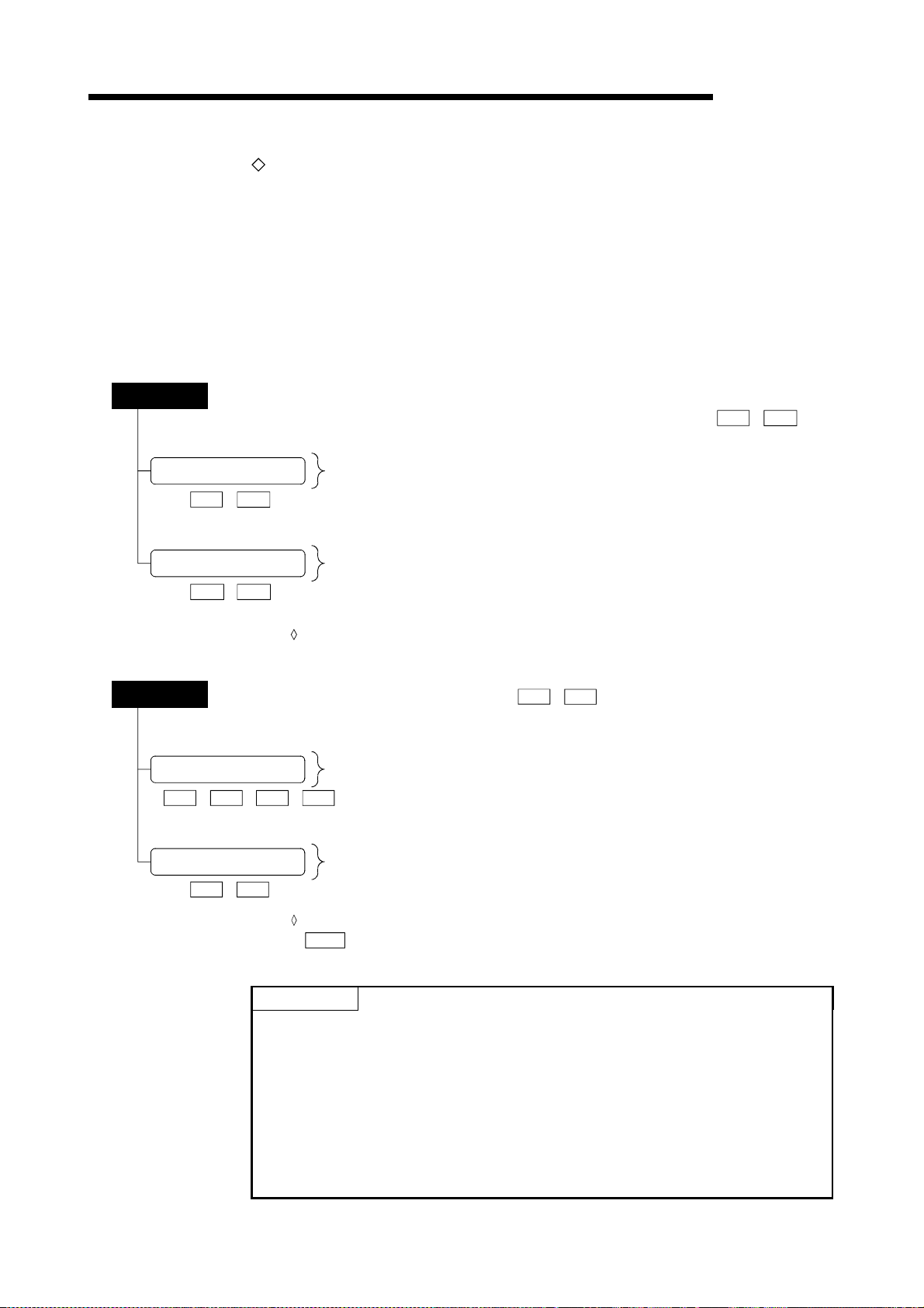
5 DATA USED FOR POSITIONING CONTROL
The only valid data assigned to these parameters are the data read at the moment
when a positioning or JOG operation is started. Once the operation has started, any
modification to the data i s ig no re d .
Exceptionally, however, modifications to the following are valid even when they are
made during a positioning operation: acceleration time 0 to 3, deceleration time 0 to
3, and external start command.
• Accelerat io n ti me 0 to 3 an d de cel e ra tion time 0 to 3:
Positioning data are pre-read and pre-analyzed. Modifications to the
data four or more steps after the current step are valid.
• External command function selection: The value at the time of detection is valid.
MELSEC-Q
Monitor data (Data that indicates the control state. Stored in the buffer memory, and monitors as necessary.)
:
Md.1
to
Md.48
System monitor data Monitors the QD75 specifications and the operation history.
)
Md.1
Axis monitor data
)
Md.20
to
to
Md.19
Md.48
)
)
Monitors the data related to the operating axis, such as the current position
and speed.
The data is monitored with the sequence program or peripheral device. In this chapter,
the method using the peripheral device will be explained.
Control data
System control data
)
Cd.1 Cd.2
(Data for user to control positioning system.)
Performs write/initialization, etc. of the "setting data" in the module.
,
Cd.42
)
to
,
Cd.41
:
Cd.1
to
Cd.42
Axis control data
)
to
Cd.3)Cd.40
(1) The "setting data" is created for each axis.
(2) The "setting data" parameters have determined default values, and are set to
(3) The "setting data" can be initialized with GX Configurator-QP or the sequence
(4) It is recommended to set the "setting data" with GX Configurator-QP. When
Makes settings related to the operation, and controls the speed change during
operation, and stops/resta rts th e opera tio n.
Control using the control data is carried out with the sequence program.
" Deceleration start flag valid" is valid for only the value at the time
Cd.41
when the PLC READY signal [Y0] turns from OFF to ON.
POINT
the default values before shipment from the factory. (Parameters related to
axes that are not used are left at the default value.)
program.
executed with the sequence program, many sequence programs and devices
must be used. This will not only complicate the program, but will also increase
the scan time.
5 - 3
Page 92

5 DATA USED FOR POSITIONING CONTROL
5.1.2 Setting items for positioning parameter s
The table below lists items set to the positioning parameters. Setting of positioning
parameters is similarly done for individual axes for all controls achieved by the QD75.
For details of controls, refer to Section 2. For details of setting items, refer to Section
5.2 "List of parameters".
Control Major positioning control Manual control
Position control Other control
MELSEC-Q
Positioning pa ra meter
Unit setting –
Pr.1
No. of pulses per rotation (Ap)
Pr.2
(Unit: pulse)
Pr.3 Movement amount per rotation (Al)
Pr.4
Unit magnification (Am)
Pr.5
Pulse output mode –
Basic parameters 1
Pr.6
Rotation direction setting –
Pr.7
Bias speed at st ar t – ––– –
Speed limit value –– 12.4.1
Pr.8
Acceleration time 0 –––
Pr.9
Basic
parameters 2
Detailed parameters 1
: Always set
: Set as required (Read "–" when not required.)
: Setting not possible
: Setting restricted
– : Setting not required. (This is an irrelevant item, so the set value will be ignored. If the value is the default value or within the setting range, there is no
Deceleration time 0 –––
Pr.10
Pr.11 Back compensation amoun t –– 12.3.1
Pr.12 Software stroke limit upper limit value – ––
Pr.13 Software stroke limit lower limit value – ––
Pr.14 Software stroke limit selection – ––
Software stroke limit valid/invalid
Pr.15
selection
Pr.16 Command in-position width – – ––––
Pr.17 Torque limit setting value –– 12.4.2
Pr.18 M code ON signal output ti ming – – – – 12.7.3
Speed switch in g mod e – – –––– –
Pr.19
Pr.20 Interpolation sp ee d des ign at ion meth od – ––––– –
Current feed value during speed control – – – – –––– –
Pr.21
Pr.22 Input signal logic selection –
Pr.23 Output signal logic selection –
Manual pulse gene ra tor in pu t se le ct io n – – – – – – – – ––
Pr.24
Pr.150
Speed-posit ion fu nct ion se lec t ion – – – – – –––– –
problem.)
OPR control
1-axis linear con tr ol
2/3/4-axis linear interpolation control
1-axis fixed- fe ed contr o l
2/3/4-axis fixed-feed control
2-axis circular interpolation control
1 to 4 axis speed control
Speed-posit ion or position-speed
control
–– – –––
Current value changing
JUMP instruction, NOP instruction,
LOOP to LEND
Manual pulse generator operation
JOG operation
Inching opera t ion
12.3.2
12.7.7
12.4.3
12.7.6
Related sub function
5 - 4
Page 93

5 DATA USED FOR POSITIONING CONTROL
MELSEC-Q
Control Major positioning control Manual control
Positioning pa ra meter
Acceleration time 1 –––
Pr.25
Acceleration time 2 –––
Pr.26
Acceleration time 3 –––
Pr.27
Deceleration time 1 –––
Pr.28
Pr.29
Deceleration time 2 –––
Pr.30
Deceleration time 3 –––
Pr.31
JOG speed limit value –– – –––––– 12.4.1
Pr.32
JOG operation acceleration time selection – – – – – – – – – –
Pr.33
JOG operation deceleration time selection – – – – – – – – – –
Acceleration /de ce ler at io n proc es s
Pr.34
selection
Pr.35
S-pattern pro por tio n –––
Detailed parameters 2
Pr.36
Sudden stop dece le ra t ion ti me –––
Pr.37
Stop group 1 sudden stop selection ––– –
Pr.38
Stop group 2 sudden stop selection ––– –
Pr.39
Stop group 3 sudden stop selection ––– –
Pr.40
Positioning co mp le te s igna l ou tpu t time – ––– –
Pr.41
Allowable circu l ar inter po la tio n er ror wid t h – – – –––––– –
Pr.42
External command function selection ––
: Always set
: Set as required ("–" when not set)
– : Setting not required (This is an irrelevant item, so the setting value will be ignored. If the value is the default value or within the setting range, there is no
problem.)
OPR control
Position control Other control
1-axis linear con tr ol
2/3/4-axis linear interpolation control
1-axis fixed- fe ed contr o l
2/3/4-axis fixed-feed control
2-axis circular interpolation control
1 to 4 axis speed control
Speed-posit ion or position-speed
control
–––
Current value ch ang i ng
JUMP instruction, NOP instruction,
LOOP to LEND
Manual pulse generator operation
JOG operation
Inching opera t ion
12.7.7
12.7.7
12.5.1
12.7.2
Related sub function
Checking the positioning parameters
Pr.1
(1) When the "PLC READY signal [Y0]" output from the PLC CPU to the QD75
(2) When the test operation button is turned ON in the test mode using GX
(3) When an error check is carried out with GX Configurator-QP
Pr.42
to
are checked with the following timing.
changes from OFF to ON
Configurator-QP
REMARK
•
"High-level positioning control" is carried out in combination with the "major
positioning control".
Refer to the "major positioning control" parameter settings for details on the
parameters required for "high-level positioning control".
5 - 5
Page 94
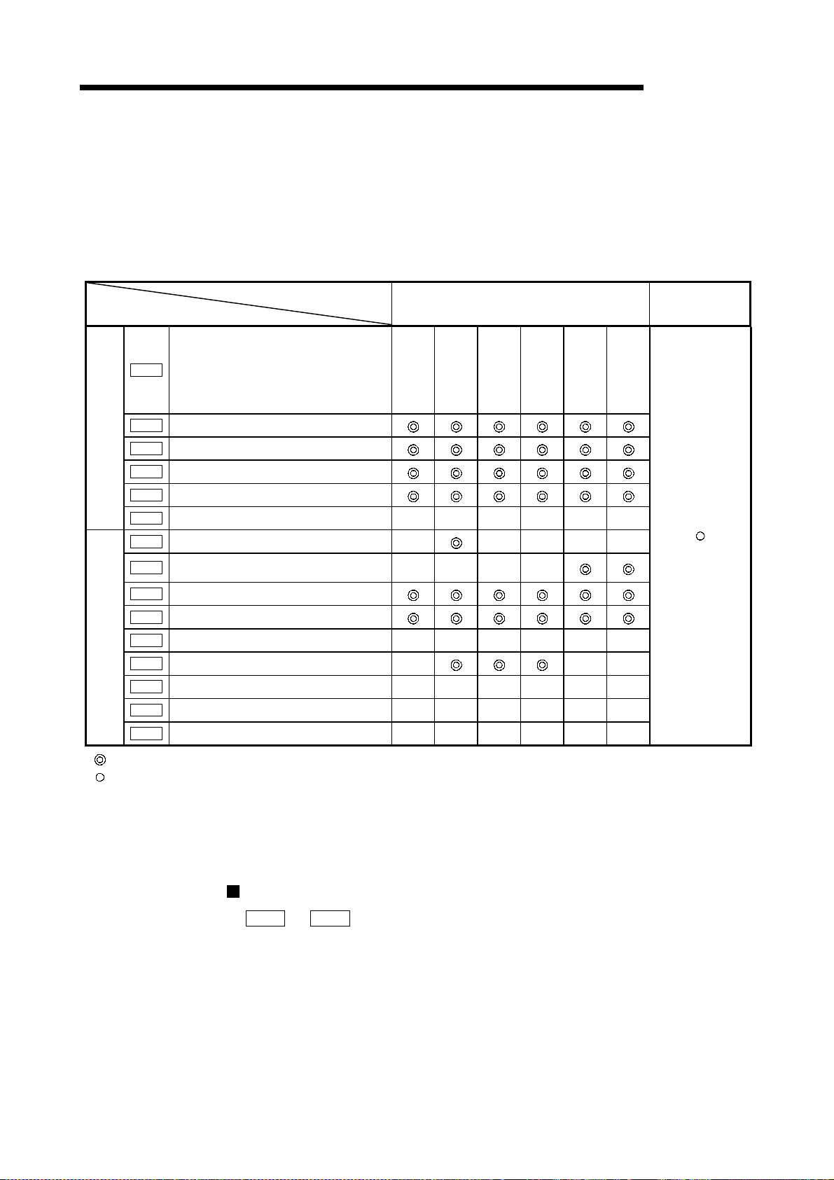
5 DATA USED FOR POSITIONING CONTROL
5.1.3 Setting items for OPR parameters
When carrying out "OPR control", the "OPR parameters" must be set. The setting
items for the "OPR parameters" are shown below.
The "OPR parameters" are set commonly for each axis.
Refer to Ch ap te r 8 "O PR co nt ro l" fo r d et ails on the "OPR con t ro l" , an d t o S e cti on 5.2
"List of parameters" for details on each setting item.
OPR control
OPR parameters
Pr.43
OPR method
Near-point dog
Pr.44
OPR direction
Pr.45
OP address
Pr.46
OPR basic parameters
OPR detailed parameters
OPR speed
Pr.47
Creep speed
Pr.48
OPR retry R R R – R R
Pr.49
OPR dwell time – ––––
Setting for the movement amount after near-
Pr.50
point dog ON
Pr.51
OPR acceleration time selection
Pr.52
OPR deceleration time selection
Pr.53
OP shift amount S S S S S S
Pr.54
OPR torque limit value – ––
Pr.55
Deviation counter clear signal output time C C C C C –
Pr.56
Speed designation during OP shift S S S S S S
Pr.57
Dwell time during OPR retry R R R – R R
––––
Machine OPR control
method
Stopper method1)Stopper method2)Stopper method
MELSEC-Q
Fast
OPR control
3)
Count method 1)
Count method 2)
: Always set
: Preset parameters are used for machine OPR control.
– : Setting not required (This is an irrelevant item, so the setting value will be ignored. If the value is the default value or
within the setting range, there is no problem.)
R : Set when using the "12.2.1 OPR retry function". ("–" when not set.)
S : Set when using the "12.2.2
OP shift function". ("–" when not set.)
C : Set the deviation counter clear signal output time. (Read as "–" when the setting is not required.)
Checking the OPR parameters.
Pr.43
(1) When the "PLC READY signal [Y0]" output from the PLC CPU to the QD75
changes from OFF to ON
(2) When the test operation button is turned ON in the test mode using GX
Configurator-QP
(3) When an error check is carried out with GX Configurator-QP
to
Pr.57
are checked with the following timing.
5 - 6
Page 95

5 DATA USED FOR POSITIONING CONTROL
5.1.4 Setting items for positioning data
Positioning data must be set for carrying out any "major positioning control". The table
below lists the items to be set for producing the positioning data.
One to 600 positioning data items can be set for each axis.
For details of the major positioning controls, refer to Chapter 9 "Major Positioning
Control". For details of the individual setting items, refer to Section 5.3 "List of
positioning data".
Major positioning control Position control Other control
1-axis linear con tr ol
2/3/4-axis linear
interpolation control
1-axis fixed- fe ed contr o l
2/3/4-axis fixed-feed control
2-axis circular interpolation
control
Positioning da ta
Independent
positioning
control
Operation
Da.1
pattern
Da.2
Control system
Da.3
Acceleration time No.
Da.4
Deceleration time No.
Axis to be
Da.5
interpolated
Positioning ad dre s s/
Da.6
movement amount
Da.7
Arc address
Da.8
Command speed
Dwell t ime
Da.9
(JUMP destination
positioning data No.)
M code
Da.10
(JUMP condi tion data No.)
:Always set
:Set as required (Read "–" when not required.)
:Setting not possible
– :Setting not required.
(This is an irr e le va nt ite m, so the se t va lu e w i ll be i gnor ed . I f th e va lue is the def au lt va lu e or with i n th e se t ting ran g e , there i s no pr oble m. )
:Two control systems are available: the absolute (ABS) system and incremental (INC) system.
Continuous
positioning
control
Continuous path
control
: 2 axes
– : 1/3/4 axes
Fixed-
Circular
Linear 1
Linear 2
Linear 3
Linear 4
feed 1
Fixedfeed 2
Fixedfeed 3
Fixedfeed 4
–––––––
––
sub
Circular
right
Circular
left
1 to 4 axis speed control
Forward
run speed 1
Reverse run
speed 1
Forward
run speed 2
Reverse run
speed 2
Forward
run speed 3
Reverse run
speed 3
Forward
run speed 4
Reverse run
speed 4
– –
––––
Speed-posit ion swi t ch ing
Forward
run
speed/
position
Reverse
run
speed/
position
control
Forward
position/
Reverse
position/
Position-s pee d sw it ch ing
run
speed
run
speed
control
NOP instr u ct i on
– –––
– –––
– –––
NOP
instruction
–––––
–––––
–
–
–
Current value ch ang i ng
Current
value
changing
New
address
JUMP
instruction
––––
––––
––––
JUMP
destination
–
positioning
data No.
JUMP
condition
data No.
MELSEC-Q
JUMP instruction
–––
LOOP
LOOP LEND
––
No. of
LOOP to
LEND
repetitions
LEND
–
5 - 7
Page 96

5 DATA USED FOR POSITIONING CONTROL
Checking the positioning data
MELSEC-Q
The items
(1) Startup of a positioning operation
(2) Error check performed by GX Configurator-QP
Da.1
to
Da.10
are checked at the following timings:
5 - 8
Page 97

5 DATA USED FOR POSITIONING CONTROL
MEMO
MELSEC-Q
5 - 9
Page 98

5 DATA USED FOR POSITIONING CONTROL
5.1.5 Setting items for block start data
The "block start data" must be set wh en carry i ng out "hi g h-l evel po siti oni ng con trol".
The setting items for the " block start data" are shown below.
Up to 50 points of " block start data" can be set for each axis.
Refer to Chapter 10 "High-level Positioning Control" for details on the "high-level
positioning control", and to Section 5.4 "List of block start data" for details on each
setting item.
MELSEC-Q
High-level positioning
control
Block start data
Da.11
Da.12
Da.13
Da.14
Shape (end/continue)
Start data No.
Special start instruction –
Parameter –
: Set as required ("–" when not set)
– : Setting not required (This is an irrelevant item, so the setting value will be ignored. If the value is the default value or within the
setting range, there is no problem.)
Block start
(Normal start)
Condition
start
Wait s t a rt
Simultaneous
start
Repeated
start
(FOR loop)
Repeated
condition)
Checking the block start data
Da.11toDa.14
(1) When the "Block start data" starts
(2) When an error check is carried out with GX Configurator-QP
are checked with the following timing.
start
(FOR
5 - 10
Page 99

5 DATA USED FOR POSITIONING CONTROL
5.1.6 Setting items for condition data
When carrying out "high-level positioning control" or using the JUMP instruction in the
"major positioning control", the "condition data" must be set as required. The setting
items for the "condition data" are shown below.
Up to 10 "condition data" items can be set for each axis.
Refer to Chapter 10 "High-level Positioning Control" for details on the "high-level
positioning control", and to Section 5.5" List of condition data" for details on each
setting item.
MELSEC-Q
Control
Condition data
Da.15
Condition target – – –
Da.16
Condition operator – – –
Da.17
Address – – ––
Da.18
Parameter 1 – – –
Da.19
Parameter 2 – – –
: Set as required ("–" when not set)
: Setting limited
– : Setting not required (This is an irrelevant item, so the setting value will be ignored. If the value is the default value or within the
setting range, there is no problem.)
Major positioning
control
Other than
JUMP
instruction
instruction
JUMP
Block start
(Normal
start )
Condition
start
High-level positioning control
Simul-
Wait s t a rt
taneous
start
Repeated
start
(FOR
loop)
Checking the condition data
Da.15toDa.19
are checked with the following timing.
Repeated
start
(FOR
condition)
(1) When the " Block start data" starts
(2) When "JUMP instruction" starts
(3) When an error check is carried out with GX Configurator-QP
5 - 11
Page 100

5 DATA USED FOR POSITIONING CONTROL
5.1.7 Types and roles of monitor data
The monitor data area in the buffer memory stores data relating to the operating state
of the positioning system, which are monitored as required while the positioning
system is operating.
The following da t a a re available for monitoring.
•
System monitoring:
Monitoring of the QD75 configuration and operation history (through the system
Md.1
monitor data
•
Axis operation monitoring:
through
Monitoring of the current position and speed, and other data related to the
movements of axes (through the axis monitor data
Md.19
MELSEC-Q
)
Md.20
through
Md.48
)
The axis monitor data are refreshed every 1.8 ms. Note that "
feed value", "
input/output signal" are refreshed every 56.8ms. Also, "
updated when the "M code ON signal [X4, X5, X6, X7]" turns ON.
[1] Monitoring the system
Monitoring the positioning system operation history
Monitoring details Corresponding item
Whether the system is in the test mode or not
Start information
Start No.
History of data that
started an operation
History of all errors
History of all warnings
Number of write accesses
to the flash ROM after the
power is switched ON
Start
Error upon starting
Latest pointer No.
Axis in which the error occurred
Axis error No.
Axis error occurrence
Latest pointer No.
Axis in which the warning occurred
Axis warning No.
Axis warning
occurrence
Latest pointer No.
Number of write accesses to flash ROM
Md.22
Feedrate", "
Hour
Minute:second
Hour
Minute:second
Hour
Minute:second
Md.28
Md.1
Md.3
Md.4
Md.5
Md.6
Md.7
Md.8
Md.9
Md.10
Md.11
Md.12
Md.13
Md.14
Md.15
Md.16
Md.17
Md.18
Md.19
Md.21
Axis feedrate" and "
In test mode flag
Start information
Start No.
Start (Hour)
Start (Minute:second)
Error judgment
Start history pointer
Axis in which the error occurred
Axis error No.
Axis error occurrence Hour
Axis error occurrence Minute:second
Error history pointer
Axis in which the warning occurred
Axis warning No.
Axis warning occurrence (Hour)
Axis warning occurrence (Minute:second)
Warning history pointer
No. of write accesses to flash ROM
Md.30
Md.23
Machine
External
Valid M code", is
5 - 12
 Loading...