

Page 1

MELSEC-Q QD73A1 Positioning Module
User's Manual
-QD73A1
Page 2

Page 3
SAFETY PRECAUTIONS
WARNING
CAUTION
Indicates that incorrect handling may cause hazardous conditions,
resulting in death or severe injury.
Indicates that incorrect handling may cause hazardous conditions,
resulting in minor or moderate injury or property damage.
(Read these precautions before using this product.)
Before using this product, please read this manual and the relevant manuals carefully and pay full attention
to safety to handle the product correctly.
The precautions given in this manual are concerned with this product only. For the safety precautions of the
programmable controller system, refer to the user’s manual for the CPU module used.
In this manual, the safety precautions are classified into two levels: " WARNING" and " CAUTION".
Under some circumstances, failure to observe the precautions given under " CAUTION" may lead to
serious consequences.
Observe the precautions of both levels because they are important for personal and system safety.
Make sure that the end users read this manual and then keep the manual in a safe place for future
reference.
[Design Precautions]
WARNING
● Configure safety circuits external to the programmable controller to ensure that the entire system
operates safely even when a fault occurs in the external power supply or the programmable controller.
Failure to do so may result in an accident due to an incorrect output or malfunction.
(1) When using a servo amplifier with Servo ON signal, connect the signal to the module. When using
a servo amplifier whose control cannot be stopped through Servo ON signal, satisfy the following.
• Analog voltage must be 0V (motor stop) to power off the programmable controller.
(2) Emergency stop circuits, protection circuits, and protective interlock circuits for conflicting
operations (such as forward/reverse rotations or upper/lower limit positioning) must be configured
external to the programmable controller.
(3) OPR (Original Point Return) is controlled by two kinds of data: OPR direction and OPR speed.
Deceleration starts when the near-point dog turns on. If an incorrect OPR direction is set, motion
control may continue without deceleration. To prevent machine damage caused by this, configure
an interlock circuit external to the programmable controller.
● Do not write any data to the "system area" of the buffer memory in the intelligent function module.
Also, do not use any "use prohibited" signal as an output signal from the CPU module to the intelligent
function module. Doing so may cause malfunction of the programmable controller system.
1
Page 4

CAUTION
● Do not install the connection cables for external I/O signals and for the drive unit together with the
main circuit lines, power cables, or load circuit lines of a device other than the programmable
controller.
Keep a distance of 100mm or more between them.
Failure to do so may result in malfunction due to noise, surges, and induction.
[Installation Precautions]
CAUTION
● Use the programmable controller in an environment that meets the general specifications in the user’s
manual for the CPU module used.
Failure to do so may result in electric shock, fire, malfunction, or damage to or deterioration of the
product.
● To mount the module, while pressing the module mounting lever located in the lower part of the
module, fully insert the module fixing projection(s) into the hole(s) in the base unit and press the
module until it snaps into place.
Incorrect mounting may cause malfunction, failure or drop of the module.
When using the programmable controller in an environment of frequent vibrations, fix the module with
a screw.
● Tighten the screws within the specified torque range.
Undertightening can cause drop of the screw, short circuit or malfunction.
Overtightening can damage the screw and/or module, resulting in drop, short circuit, or malfunction.
● Securely connect the drive unit connector and external device connector to the connector on the
module. Poor contact may cause incorrect input or output.
● Do not directly touch any conductive parts and electronic components of the module.
Doing so can cause malfunction or failure of the module.
● Shut off the external power supply (all phases) used in the system before mounting or removing the
module. Failure to do so may result in damage to the product.
2
Page 5

[Wiring Precautions]
WARNING
● Shut off the external power supply (all phases) used in the system before installation and wiring.
Failure to do so may result in electric shock or cause the module to fail or malfunction.
● After installation and wiring, attach the included terminal cover to the module before turning it on for
operation. Failure to do so may result in electric shock.
CAUTION
● Check the rated voltage and terminal layout before wiring to the module, and connect the cables
correctly.
Connecting a power supply with a different voltage rating or incorrect wiring may cause a fire or
failure.
● Use applicable solderless terminals and tighten them within the specified torque range.
If any spade solderless terminal is used, it may be disconnected when the terminal screw comes
loose, resulting in failure.
● Tighten the connector screws within the specified torque range.
Undertightening can cause short circuit, fire, or malfunction.
Overtightening can damage the screw and/or module, resulting in drop, short circuit, fire, or
malfunction.
● Connectors for external devices must be crimped with the tool specified by the manufacturer or must
be correctly soldered.
Incomplete connections may cause short circuit, fire, or malfunction.
● Place the cables in a duct or clamp them.
If not, dangling cable may swing or inadvertently be pulled, resulting in damage to the module or
cables or malfunction due to poor contact.
● When disconnecting the cable from the module, do not pull the cable by the cable part. For the cable
with connector, hold the connector part of the cable.
Pulling the cable connected to the module may result in malfunction or damage to the module or
cable.
● Prevent foreign matter such as dust or wire chips from entering the module. Such foreign matter can
cause a fire, failure, or malfunction.
● A protective film is attached to the top of the module to prevent foreign matter, such as wire chips,
from entering the module during wiring. Do not remove the film during wiring. Remove it for heat
dissipation before system operation.
3
Page 6
[Startup and Maintenance Precautions]
WARNING
● Shut off the external power supply (all phases) used in the system before cleaning the module or
retightening the connector screws. Failure to do so may result in electric shock.
CAUTION
● Do not disassemble or modify the module.
Doing so may cause failure, malfunction, injury, or a fire.
● Shut off the external power supply (all phases) used in the system before mounting or removing a
module. Failure to do so may cause the module to fail or malfunction.
● After the first use of the product, do not mount/remove the module to/from the base unit, and the
terminal block to/from the module more than 50 times (IEC 61131-2 compliant) respectively.
Exceeding the limit may cause malfunction.
● Before testing operation, set a low speed value for the speed limit parameter so that the operation can
be stopped immediately upon occurrence of a hazardous condition.
● Before handling the module, touch a conducting object such as a grounded metal to discharge the
static electricity from the human body. Failure to do so may cause the module to fail or malfunction.
[Precaution during operation]
CAUTION
● When changing data and operating status, and modifying program of the running programmable
controller from an external device such as a personal computer connected to an intelligent function
module, read relevant manuals carefully and ensure the safety before operation. Incorrect change or
modification may cause system malfunction, damage to the machines, or accidents.
[Disposal Precaution]
CAUTION
● When disposing of this product, treat it as industrial waste.
4
Page 7

CONDITIONS OF USE FOR THE PRODUCT
(1) Mitsubishi programmable controller ("the PRODUCT") shall be used in conditions;
i) where any problem, fault or failure occurring in the PRODUCT, if any, shall not lead to any major
or serious accident; and
ii) where the backup and fail-safe function are systematically or automatically provided outside of
the PRODUCT for the case of any problem, fault or failure occurring in the PRODUCT.
(2) The PRODUCT has been designed and manufactured for the purpose of being used in general
industries.
MITSUBISHI SHALL HAVE NO RESPONSIBILITY OR LIABILITY (INCLUDING, BUT NOT
LIMITED TO ANY AND ALL RESPONSIBILITY OR LIABILITY BASED ON CONTRACT,
WARRANTY, TORT, PRODUCT LIABILITY) FOR ANY INJURY OR DEATH TO PERSONS OR
LOSS OR DAMAGE TO PROPERTY CAUSED BY the PRODUCT THAT ARE OPERATED OR
USED IN APPLICATION NOT INTENDED OR EXCLUDED BY INSTRUCTIONS, PRECAUTIONS,
OR WARNING CONTAINED IN MITSUBISHI'S USER, INSTRUCTION AND/OR SAFETY
MANUALS, TECHNICAL BULLETINS AND GUIDELINES FOR the PRODUCT.
("Prohibited Application")
Prohibited Applications include, but not limited to, the use of the PRODUCT in;
• Nuclear Power Plants and any other power plants operated by Power companies, and/or any
other cases in which the public could be affected if any problem or fault occurs in the PRODUCT.
• Railway companies or Public service purposes, and/or any other cases in which establishment of
a special quality assurance system is required by the Purchaser or End User.
• Aircraft or Aerospace, Medical applications, Train equipment, transport equipment such as
Elevator and Escalator, Incineration and Fuel devices, Vehicles, Manned transportation,
Equipment for Recreation and Amusement, and Safety devices, handling of Nuclear or
Hazardous Materials or Chemicals, Mining and Drilling, and/or other applications where there is a
significant risk of injury to the public or property.
Notwithstanding the above, restrictions Mitsubishi may in its sole discretion, authorize use of the
PRODUCT in one or more of the Prohibited Applications, provided that the usage of the PRODUCT
is limited only for the specific applications agreed to by Mitsubishi and provided further that no
special quality assurance or fail-safe, redundant or other safety features which exceed the general
specifications of the PRODUCTs are required. For details, please contact the Mitsubishi
representative in your region.
5
Page 8

INTRODUCTION
Remark
Thank you for purchasing the Mitsubishi MELSEC-Q series programmable controllers.
This manual describes the operating procedure, system configuration, parameter settings, functions, programming,
and troubleshooting of the QD73A1 positioning module (hereafter abbreviated as QD73A1).
Before using this product, please read this manual and the relevant manuals carefully and develop familiarity with the
functions and performance of the MELSEC-Q series programmable controller to handle the product correctly.
When applying the program examples introduced in this manual to an actual system, ensure the applicability and
confirm that it will not cause system control problems.
Relevant module: QD73A1
● Unless otherwise specified, this manual describes the program examples in which the I/O numbers of X/Y10 to X/Y2F are
assigned for the QD73A1.
For I/O number assignment, refer to the following manuals.
QnUCPU Users Manual (Function Explanation, Program Fundamentals)
Qn(H)/QnPH/QnPRHCPU User's Manual (Function Explanation, Program Fundamentals)
● Operating procedures are explained using GX Works2. When using GX Developer, refer to the following.
Page 275, Appendix 4
6
Page 9

COMPLIANCE WITH EMC AND LOW VOLTAGE
DIRECTIVES
(1) Method of ensuring compliance
To ensure that Mitsubishi programmable controllers maintain EMC and Low Voltage Directives when incorporated
into other machinery or equipment, certain measures may be necessary. Please refer to one of the following
manuals.
• QCPU User's Manual (Hardware Design, Maintenance and Inspection)
• Safety Guidelines
(This manual is included with the CPU module or base unit.)
The CE mark on the side of the programmable controller indicates compliance with EMC and Low Voltage
Directives.
(2) Additional measures
To ensure that this product maintains EMC and Low Voltage Directives, please refer to Page 64, Section 4.6.1.
7
Page 10

RELEVANT MANUALS
(3) CPU module user's manual
Manual name
<manual number (model code)>
QCPU User's Manual (Hardware Design, Maintenance and
Inspection)
<SH-080483ENG, 13JR73>
QnUCPU Users Manual (Function Explanation, Program
Fundamentals)
<SH-080807ENG, 13JZ27>
Qn(H)/QnPH/QnPRHCPU User's Manual (Function
Explanation, Program Fundamentals)
<SH-080808ENG, 13JZ28>
(4) Operating manual
Manual name
<manual number (model code)>
GX Works2 Version1 Operating Manual (Common)
<SH-080779ENG, 13JU63>
GX Developer Version 8 Operating Manual
<SH-080373E, 13JU41>
Description
Specifications of the hardware (CPU modules, power supply modules,
base units, extension cables, and memory cards), system maintenance
and inspection, troubleshooting, and error codes
Functions, methods, and devices for programming
Description
System configuration, parameter settings, and online operations (common
to Simple project and Structured project) of GX Works2
Operating methods of GX Developer, such as programming, printing,
monitoring, and debugging
8
Page 11

Memo
9
Page 12

CONTENTS
CONTENTS
SAFETY PRECAUTIONS . . . . . . . . . . . . . . . . . . . . . . . . . . . . . . . . . . . . . . . . . . . . . . . . . . . . . . . . . . . . . 1
CONDITIONS OF USE FOR THE PRODUCT . . . . . . . . . . . . . . . . . . . . . . . . . . . . . . . . . . . . . . . . . . . . . 5
INTRODUCTION . . . . . . . . . . . . . . . . . . . . . . . . . . . . . . . . . . . . . . . . . . . . . . . . . . . . . . . . . . . . . . . . . . . . 6
COMPLIANCE WITH EMC AND LOW VOLTAGE DIRECTIVES . . . . . . . . . . . . . . . . . . . . . . . . . . . . . . . 7
RELEVANT MANUALS . . . . . . . . . . . . . . . . . . . . . . . . . . . . . . . . . . . . . . . . . . . . . . . . . . . . . . . . . . . . . . . 8
MANUAL PAGE ORGANIZATION . . . . . . . . . . . . . . . . . . . . . . . . . . . . . . . . . . . . . . . . . . . . . . . . . . . . . . 14
TERMS . . . . . . . . . . . . . . . . . . . . . . . . . . . . . . . . . . . . . . . . . . . . . . . . . . . . . . . . . . . . . . . . . . . . . . . . . . 16
PACKING LIST . . . . . . . . . . . . . . . . . . . . . . . . . . . . . . . . . . . . . . . . . . . . . . . . . . . . . . . . . . . . . . . . . . . . 16
CHAPTER 1 OVERVIEW 17
1.1 Features . . . . . . . . . . . . . . . . . . . . . . . . . . . . . . . . . . . . . . . . . . . . . . . . . . . . . . . . . . . . . . . . . . 18
1.2 Signal Transmission Between the QD73A1 and Others. . . . . . . . . . . . . . . . . . . . . . . . . . . . . .19
CHAPTER 2 SYSTEM CONFIGURATION 21
2.1 Applicable Systems . . . . . . . . . . . . . . . . . . . . . . . . . . . . . . . . . . . . . . . . . . . . . . . . . . . . . . . . . 21
2.2 How to Check the Function Version and Serial Number. . . . . . . . . . . . . . . . . . . . . . . . . . . . . .23
CHAPTER 3 SPECIFICATIONS 25
3.1 Performance Specifications . . . . . . . . . . . . . . . . . . . . . . . . . . . . . . . . . . . . . . . . . . . . . . . . . . . 25
3.2 Number of Parameter Settings . . . . . . . . . . . . . . . . . . . . . . . . . . . . . . . . . . . . . . . . . . . . . . . . .26
3.3 List of Functions . . . . . . . . . . . . . . . . . . . . . . . . . . . . . . . . . . . . . . . . . . . . . . . . . . . . . . . . . . . .27
3.4 I/O Signals from/to the CPU Module. . . . . . . . . . . . . . . . . . . . . . . . . . . . . . . . . . . . . . . . . . . . .30
3.4.1 I/O signal list. . . . . . . . . . . . . . . . . . . . . . . . . . . . . . . . . . . . . . . . . . . . . . . . . . . . . . . . . . . . . . 30
3.4.2 Details of input signals . . . . . . . . . . . . . . . . . . . . . . . . . . . . . . . . . . . . . . . . . . . . . . . . . . . . . . 32
3.4.3 Details of output signals. . . . . . . . . . . . . . . . . . . . . . . . . . . . . . . . . . . . . . . . . . . . . . . . . . . . . 37
3.5 Specifications of I/O Interfaces with External Devices . . . . . . . . . . . . . . . . . . . . . . . . . . . . . . .40
3.5.1 Electrical specifications of I/O signals . . . . . . . . . . . . . . . . . . . . . . . . . . . . . . . . . . . . . . . . . . 40
3.5.2 Signal layout for external device connectors . . . . . . . . . . . . . . . . . . . . . . . . . . . . . . . . . . . . . 42
3.5.3 List of I/O signal details . . . . . . . . . . . . . . . . . . . . . . . . . . . . . . . . . . . . . . . . . . . . . . . . . . . . . 43
3.5.4 I/O interface internal circuit . . . . . . . . . . . . . . . . . . . . . . . . . . . . . . . . . . . . . . . . . . . . . . . . . . 45
3.6 Memory Configuration and Use . . . . . . . . . . . . . . . . . . . . . . . . . . . . . . . . . . . . . . . . . . . . . . . .47
3.7 List of Buffer Memory Addresses . . . . . . . . . . . . . . . . . . . . . . . . . . . . . . . . . . . . . . . . . . . . . . .48
CHAPTER 4 SETTINGS AND PROCEDURE BEFORE OPERATION 54
4.1 Handling Precautions . . . . . . . . . . . . . . . . . . . . . . . . . . . . . . . . . . . . . . . . . . . . . . . . . . . . . . . .54
4.2 Settings and Procedure Before Operation . . . . . . . . . . . . . . . . . . . . . . . . . . . . . . . . . . . . . . . .55
4.3 Part Names. . . . . . . . . . . . . . . . . . . . . . . . . . . . . . . . . . . . . . . . . . . . . . . . . . . . . . . . . . . . . . . . 56
4.4 LED. . . . . . . . . . . . . . . . . . . . . . . . . . . . . . . . . . . . . . . . . . . . . . . . . . . . . . . . . . . . . . . . . . . . . .58
4.5 Zero/gain Adjustment . . . . . . . . . . . . . . . . . . . . . . . . . . . . . . . . . . . . . . . . . . . . . . . . . . . . . . . .59
4.6 Wiring . . . . . . . . . . . . . . . . . . . . . . . . . . . . . . . . . . . . . . . . . . . . . . . . . . . . . . . . . . . . . . . . . . . . 64
4.6.1 Wiring precautions . . . . . . . . . . . . . . . . . . . . . . . . . . . . . . . . . . . . . . . . . . . . . . . . . . . . . . . . . 64
4.6.2 Precautions when connecting an encoder . . . . . . . . . . . . . . . . . . . . . . . . . . . . . . . . . . . . . . . 66
4.6.3 External device connectors . . . . . . . . . . . . . . . . . . . . . . . . . . . . . . . . . . . . . . . . . . . . . . . . . . 69
10
Page 13

CHAPTER 5 DATA USED FOR POSITIONING 73
5.1 Types of Data . . . . . . . . . . . . . . . . . . . . . . . . . . . . . . . . . . . . . . . . . . . . . . . . . . . . . . . . . . . . . .73
5.2 Positioning Parameters. . . . . . . . . . . . . . . . . . . . . . . . . . . . . . . . . . . . . . . . . . . . . . . . . . . . . . .75
5.3 OPR Parameters . . . . . . . . . . . . . . . . . . . . . . . . . . . . . . . . . . . . . . . . . . . . . . . . . . . . . . . . . . .79
5.4 Positioning Data . . . . . . . . . . . . . . . . . . . . . . . . . . . . . . . . . . . . . . . . . . . . . . . . . . . . . . . . . . . .82
5.5 Monitor Data . . . . . . . . . . . . . . . . . . . . . . . . . . . . . . . . . . . . . . . . . . . . . . . . . . . . . . . . . . . . . . .85
5.6 Control Data . . . . . . . . . . . . . . . . . . . . . . . . . . . . . . . . . . . . . . . . . . . . . . . . . . . . . . . . . . . . . . .89
CHAPTER 6 VARIOUS SETTINGS 99
6.1 Adding a Module. . . . . . . . . . . . . . . . . . . . . . . . . . . . . . . . . . . . . . . . . . . . . . . . . . . . . . . . . . . .99
6.2 Switch Setting. . . . . . . . . . . . . . . . . . . . . . . . . . . . . . . . . . . . . . . . . . . . . . . . . . . . . . . . . . . . .100
6.2.1 Rotation direction setting . . . . . . . . . . . . . . . . . . . . . . . . . . . . . . . . . . . . . . . . . . . . . . . . . . . 101
6.2.2 Accumulated pulse setting . . . . . . . . . . . . . . . . . . . . . . . . . . . . . . . . . . . . . . . . . . . . . . . . . . 102
6.2.3 Multiplication setting. . . . . . . . . . . . . . . . . . . . . . . . . . . . . . . . . . . . . . . . . . . . . . . . . . . . . . . 104
6.2.4 OPR direction setting . . . . . . . . . . . . . . . . . . . . . . . . . . . . . . . . . . . . . . . . . . . . . . . . . . . . . . 104
6.2.5 OPR method setting. . . . . . . . . . . . . . . . . . . . . . . . . . . . . . . . . . . . . . . . . . . . . . . . . . . . . . . 104
6.2.6 Encoder I/F setting . . . . . . . . . . . . . . . . . . . . . . . . . . . . . . . . . . . . . . . . . . . . . . . . . . . . . . . . 105
6.2.7 Analog voltage resolution setting . . . . . . . . . . . . . . . . . . . . . . . . . . . . . . . . . . . . . . . . . . . . . 105
6.2.8 Feedback pulse addition/subtraction setting . . . . . . . . . . . . . . . . . . . . . . . . . . . . . . . . . . . . 106
6.2.9 Deviation counter clear setting. . . . . . . . . . . . . . . . . . . . . . . . . . . . . . . . . . . . . . . . . . . . . . . 107
6.3 Parameter Setting. . . . . . . . . . . . . . . . . . . . . . . . . . . . . . . . . . . . . . . . . . . . . . . . . . . . . . . . . .108
6.4 Positioning Data Setting . . . . . . . . . . . . . . . . . . . . . . . . . . . . . . . . . . . . . . . . . . . . . . . . . . . . . 109
6.5 Auto Refresh. . . . . . . . . . . . . . . . . . . . . . . . . . . . . . . . . . . . . . . . . . . . . . . . . . . . . . . . . . . . . .110
CHAPTER 7 PROGRAMMING 111
7.1 Precautions on Programming . . . . . . . . . . . . . . . . . . . . . . . . . . . . . . . . . . . . . . . . . . . . . . . . .111
7.2 Programs for Positioning . . . . . . . . . . . . . . . . . . . . . . . . . . . . . . . . . . . . . . . . . . . . . . . . . . . .114
7.3 When Using the Module in a Standard System Configuration . . . . . . . . . . . . . . . . . . . . . . . .115
7.3.1 Parameter setting program . . . . . . . . . . . . . . . . . . . . . . . . . . . . . . . . . . . . . . . . . . . . . . . . . 117
7.3.2 OPR program. . . . . . . . . . . . . . . . . . . . . . . . . . . . . . . . . . . . . . . . . . . . . . . . . . . . . . . . . . . . 119
7.3.3 Major positioning control program . . . . . . . . . . . . . . . . . . . . . . . . . . . . . . . . . . . . . . . . . . . . 125
7.3.4 Fixed-feed operation program . . . . . . . . . . . . . . . . . . . . . . . . . . . . . . . . . . . . . . . . . . . . . . . 133
7.3.5 JOG operation program . . . . . . . . . . . . . . . . . . . . . . . . . . . . . . . . . . . . . . . . . . . . . . . . . . . . 135
7.3.6 Control change program . . . . . . . . . . . . . . . . . . . . . . . . . . . . . . . . . . . . . . . . . . . . . . . . . . . 137
7.3.7 Stop program during positioning . . . . . . . . . . . . . . . . . . . . . . . . . . . . . . . . . . . . . . . . . . . . . 141
7.4 When Using the Module in a Remote I/O Network . . . . . . . . . . . . . . . . . . . . . . . . . . . . . . . . .142
7.4.1 Parameter setting program . . . . . . . . . . . . . . . . . . . . . . . . . . . . . . . . . . . . . . . . . . . . . . . . . 149
7.4.2 OPR program. . . . . . . . . . . . . . . . . . . . . . . . . . . . . . . . . . . . . . . . . . . . . . . . . . . . . . . . . . . . 151
7.4.3 Major positioning control program . . . . . . . . . . . . . . . . . . . . . . . . . . . . . . . . . . . . . . . . . . . . 157
7.4.4 Fixed-feed operation program . . . . . . . . . . . . . . . . . . . . . . . . . . . . . . . . . . . . . . . . . . . . . . . 167
7.4.5 JOG operation program . . . . . . . . . . . . . . . . . . . . . . . . . . . . . . . . . . . . . . . . . . . . . . . . . . . . 170
7.4.6 Control change program . . . . . . . . . . . . . . . . . . . . . . . . . . . . . . . . . . . . . . . . . . . . . . . . . . . 172
7.4.7 Stop program during positioning . . . . . . . . . . . . . . . . . . . . . . . . . . . . . . . . . . . . . . . . . . . . . 177
11
Page 14

CHAPTER 8 OPR CONTROL 178
8.1 Overview of OPR Control . . . . . . . . . . . . . . . . . . . . . . . . . . . . . . . . . . . . . . . . . . . . . . . . . . . .178
8.2 Near-point Dog Method . . . . . . . . . . . . . . . . . . . . . . . . . . . . . . . . . . . . . . . . . . . . . . . . . . . . .179
8.3 Count Method . . . . . . . . . . . . . . . . . . . . . . . . . . . . . . . . . . . . . . . . . . . . . . . . . . . . . . . . . . . . .181
8.4 Operation Timing and Processing Time of OPR Control . . . . . . . . . . . . . . . . . . . . . . . . . . . .183
8.5 OPR Parameter Setting . . . . . . . . . . . . . . . . . . . . . . . . . . . . . . . . . . . . . . . . . . . . . . . . . . . . .184
CHAPTER 9 MAJOR POSITIONING CONTROL 185
9.1 Overview of Major Positioning Control . . . . . . . . . . . . . . . . . . . . . . . . . . . . . . . . . . . . . . . . . .185
9.2 Data Required for Major Positioning Control . . . . . . . . . . . . . . . . . . . . . . . . . . . . . . . . . . . . .186
9.3 Relation Between Each Control and Positioning Data . . . . . . . . . . . . . . . . . . . . . . . . . . . . . .187
9.4 Specifying a Positioning Address . . . . . . . . . . . . . . . . . . . . . . . . . . . . . . . . . . . . . . . . . . . . . .188
9.5 Checking the Current Value . . . . . . . . . . . . . . . . . . . . . . . . . . . . . . . . . . . . . . . . . . . . . . . . . .189
9.6 Details of Major Positioning Control . . . . . . . . . . . . . . . . . . . . . . . . . . . . . . . . . . . . . . . . . . . .190
9.6.1 Position control mode. . . . . . . . . . . . . . . . . . . . . . . . . . . . . . . . . . . . . . . . . . . . . . . . . . . . . . 191
9.6.2 Speed-position control switch mode. . . . . . . . . . . . . . . . . . . . . . . . . . . . . . . . . . . . . . . . . . . 195
9.7 Operation Timing and Processing Time of Major Positioning Control . . . . . . . . . . . . . . . . . .199
CHAPTER 10 JOG OPERATION 200
10.1 Operation of JOG Operation. . . . . . . . . . . . . . . . . . . . . . . . . . . . . . . . . . . . . . . . . . . . . . . . . .201
10.2 Operation Timing and Processing Time of JOG Operation . . . . . . . . . . . . . . . . . . . . . . . . . .206
10.3 Data Setting for JOG Operation . . . . . . . . . . . . . . . . . . . . . . . . . . . . . . . . . . . . . . . . . . . . . . .207
CHAPTER 11 CONTROL SUB FUNCTIONS 208
11.1 Electronic Gear Function . . . . . . . . . . . . . . . . . . . . . . . . . . . . . . . . . . . . . . . . . . . . . . . . . . . .209
11.2 Speed Limit Function . . . . . . . . . . . . . . . . . . . . . . . . . . . . . . . . . . . . . . . . . . . . . . . . . . . . . . .211
11.3 Stroke Limit Function . . . . . . . . . . . . . . . . . . . . . . . . . . . . . . . . . . . . . . . . . . . . . . . . . . . . . . .213
11.4 Upper Limit Switch (FLS)/Lower Limit Switch (RLS) Function . . . . . . . . . . . . . . . . . . . . . . . .215
11.5 Current Value Change Function . . . . . . . . . . . . . . . . . . . . . . . . . . . . . . . . . . . . . . . . . . . . . . .217
11.6 Speed Change Function. . . . . . . . . . . . . . . . . . . . . . . . . . . . . . . . . . . . . . . . . . . . . . . . . . . . . 218
11.7 Deviation Counter Clear Function. . . . . . . . . . . . . . . . . . . . . . . . . . . . . . . . . . . . . . . . . . . . . .220
11.8 In-position Function . . . . . . . . . . . . . . . . . . . . . . . . . . . . . . . . . . . . . . . . . . . . . . . . . . . . . . . .221
11.9 Accumulated Pulse Error Detection Function. . . . . . . . . . . . . . . . . . . . . . . . . . . . . . . . . . . . .223
11.9.1 Measuring and saving the reference value in the flash ROM . . . . . . . . . . . . . . . . . . . . . . . 225
11.9.2 Setting the accumulated pulse error detection function . . . . . . . . . . . . . . . . . . . . . . . . . . . . 226
CHAPTER 12 STOPPING AND RESTARTING CONTROL 230
12.1 Stopping Control. . . . . . . . . . . . . . . . . . . . . . . . . . . . . . . . . . . . . . . . . . . . . . . . . . . . . . . . . . .230
12.2 Restarting the Speed-position Control Switch Mode . . . . . . . . . . . . . . . . . . . . . . . . . . . . . . .234
CHAPTER 13 COMMON FUNCTIONS 236
13.1 Module Status Monitor Function . . . . . . . . . . . . . . . . . . . . . . . . . . . . . . . . . . . . . . . . . . . . . . .236
12
Page 15

13.2 Error History Function. . . . . . . . . . . . . . . . . . . . . . . . . . . . . . . . . . . . . . . . . . . . . . . . . . . . . . .238
13.3 Module Error Collection Function . . . . . . . . . . . . . . . . . . . . . . . . . . . . . . . . . . . . . . . . . . . . . .239
13.4 Error Clear Function . . . . . . . . . . . . . . . . . . . . . . . . . . . . . . . . . . . . . . . . . . . . . . . . . . . . . . . .240
CHAPTER 14 TROUBLESHOOTING 241
14.1 Checking an Error on GX Works2 . . . . . . . . . . . . . . . . . . . . . . . . . . . . . . . . . . . . . . . . . . . . .241
14.2 Troubleshooting . . . . . . . . . . . . . . . . . . . . . . . . . . . . . . . . . . . . . . . . . . . . . . . . . . . . . . . . . . .245
14.2.1 Troubleshooting procedure . . . . . . . . . . . . . . . . . . . . . . . . . . . . . . . . . . . . . . . . . . . . . . . . . 245
14.2.2 When the motor does not stop . . . . . . . . . . . . . . . . . . . . . . . . . . . . . . . . . . . . . . . . . . . . . . . 246
14.2.3 When positioning cannot be executed . . . . . . . . . . . . . . . . . . . . . . . . . . . . . . . . . . . . . . . . . 246
14.2.4 When a positioning error occurs . . . . . . . . . . . . . . . . . . . . . . . . . . . . . . . . . . . . . . . . . . . . . 247
14.2.5 When the positioning speed is different from the specified speed. . . . . . . . . . . . . . . . . . . . 248
14.2.6 When operation stops abnormally during positioning . . . . . . . . . . . . . . . . . . . . . . . . . . . . . 248
14.2.7 OPR error. . . . . . . . . . . . . . . . . . . . . . . . . . . . . . . . . . . . . . . . . . . . . . . . . . . . . . . . . . . . . . . 249
14.3 Details of Errors . . . . . . . . . . . . . . . . . . . . . . . . . . . . . . . . . . . . . . . . . . . . . . . . . . . . . . . . . . .250
14.3.1 Types of errors . . . . . . . . . . . . . . . . . . . . . . . . . . . . . . . . . . . . . . . . . . . . . . . . . . . . . . . . . . . 250
14.3.2 Storage of errors . . . . . . . . . . . . . . . . . . . . . . . . . . . . . . . . . . . . . . . . . . . . . . . . . . . . . . . . . 251
14.3.3 Error reset . . . . . . . . . . . . . . . . . . . . . . . . . . . . . . . . . . . . . . . . . . . . . . . . . . . . . . . . . . . . . . 251
14.3.4 Error code list . . . . . . . . . . . . . . . . . . . . . . . . . . . . . . . . . . . . . . . . . . . . . . . . . . . . . . . . . . . . 252
APPENDICES 263
Appendix 1 Functions Added or Changed . . . . . . . . . . . . . . . . . . . . . . . . . . . . . . . . . . . . . . . . . . . .263
Appendix 1.1 Functions added . . . . . . . . . . . . . . . . . . . . . . . . . . . . . . . . . . . . . . . . . . . 263
Appendix 1.2 Functions changed . . . . . . . . . . . . . . . . . . . . . . . . . . . . . . . . . . . . . . . . . . 263
Appendix 2 Connection Examples. . . . . . . . . . . . . . . . . . . . . . . . . . . . . . . . . . . . . . . . . . . . . . . . . .264
Appendix 2.1 Example of connection with a servo amplifier manufactured by Mitsubishi Electric
Corporation
Appendix 2.2 Example of connection with a servo amplifier manufactured by YASKAWA Electric
Corporation
Appendix 3 Comparison of the QD73A1 and the AD70/A1SD70. . . . . . . . . . . . . . . . . . . . . . . . . . .267
Appendix 4 When Using GX Developer. . . . . . . . . . . . . . . . . . . . . . . . . . . . . . . . . . . . . . . . . . . . . .275
Appendix 4.1 Operation of GX Developer . . . . . . . . . . . . . . . . . . . . . . . . . . . . . . . . . . . . 275
Appendix 5 Terms . . . . . . . . . . . . . . . . . . . . . . . . . . . . . . . . . . . . . . . . . . . . . . . . . . . . . . . . . . . . . .278
Appendix 6 External Dimensions . . . . . . . . . . . . . . . . . . . . . . . . . . . . . . . . . . . . . . . . . . . . . . . . . . .280
. . . . . . . . . . . . . . . . . . . . . . . . . . . . . . . . . . . . . . . . . . . . . . . 264
. . . . . . . . . . . . . . . . . . . . . . . . . . . . . . . . . . . . . . . . . . . . . . . 265
INDEX 282
REVISIONS . . . . . . . . . . . . . . . . . . . . . . . . . . . . . . . . . . . . . . . . . . . . . . . . . . . . . . . . . . . . . . . . . . . . . . 286
WARRANTY . . . . . . . . . . . . . . . . . . . . . . . . . . . . . . . . . . . . . . . . . . . . . . . . . . . . . . . . . . . . . . . . . . . . . 287
13
Page 16
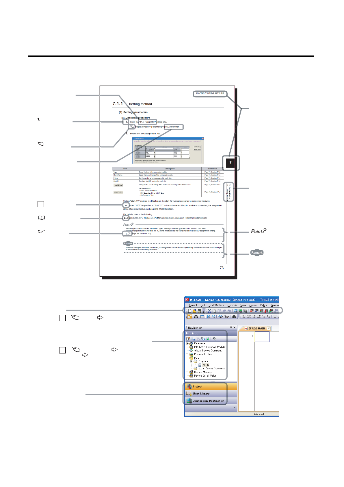
MANUAL PAGE ORGANIZATION
A window selected in the view selection area is displayed.
View selection area
[Online] [Write to PLC...]
Select [Online] on the menu bar,
and then select [Write to PLC...].
Project window
[Parameter]
[PLC Parameter]
Select [Project] from the view selection
area to open the Project window.
Menu bar
Ex.
Ex.
In the Project window, expand [Parameter] and
select [PLC Parameter].
In this manual, pages are organized and the symbols are used as shown below.
The following illustration is for explanation purpose only, and should not be referred to as an actual documentation.
"" is used for
screen names and items.
The chapter of
shows operating
procedures.
the current page is shown.
shows mouse
operations.
[ ] is used for items
in the menu bar and
the project window.
Ex.
shows setting or
operating examples.
shows reference
manuals.
shows
reference pages.
*1
*1 The mouse operation example is provided below.
The section of
the current page is shown.
shows notes that
requires attention.
shows useful
information.
14
Page 17

The following symbols are used to represent buffer memory areas in this manual. Serial numbers fit in "*".
Pr.*
Da.*
Md.*
Cd.*
Symbol Description
Symbol indicating positioning parameter and OPR parameter item
Symbol indicating positioning data item
Symbol indicating monitor data item
Symbol indicating control data item
15
Page 18

TERMS
Unless otherwise specified, this manual uses the following terms.
Term Description
QD73A1 The abbreviation for the QD73A1 positioning module
QCPU Another term for the MELSEC-Q series CPU module
Redundant CPU A generic term for the Q12PRHCPU and Q25PRHCPU
External input The abbreviation for input from connectors for external devices
External output The abbreviation for output to connectors for external devices
Programming tool Generic term for GX Works2 and GX Developer
GX Works2
GX Developer
Buffer memory
For terms related to positioning, refer to the following.
Page 278, Appendix 5
The product name of the software package for the MELSEC programmable
controllers
The memory of an intelligent function module used to store data (such as setting
values and monitored values) for communication with a CPU module
PACKING LIST
The product package contains the following.
Model Product Quantity
QD73A1 QD73A1 positioning module 1
QD73A1-U-HW Before Using the Product 1
16
Page 19
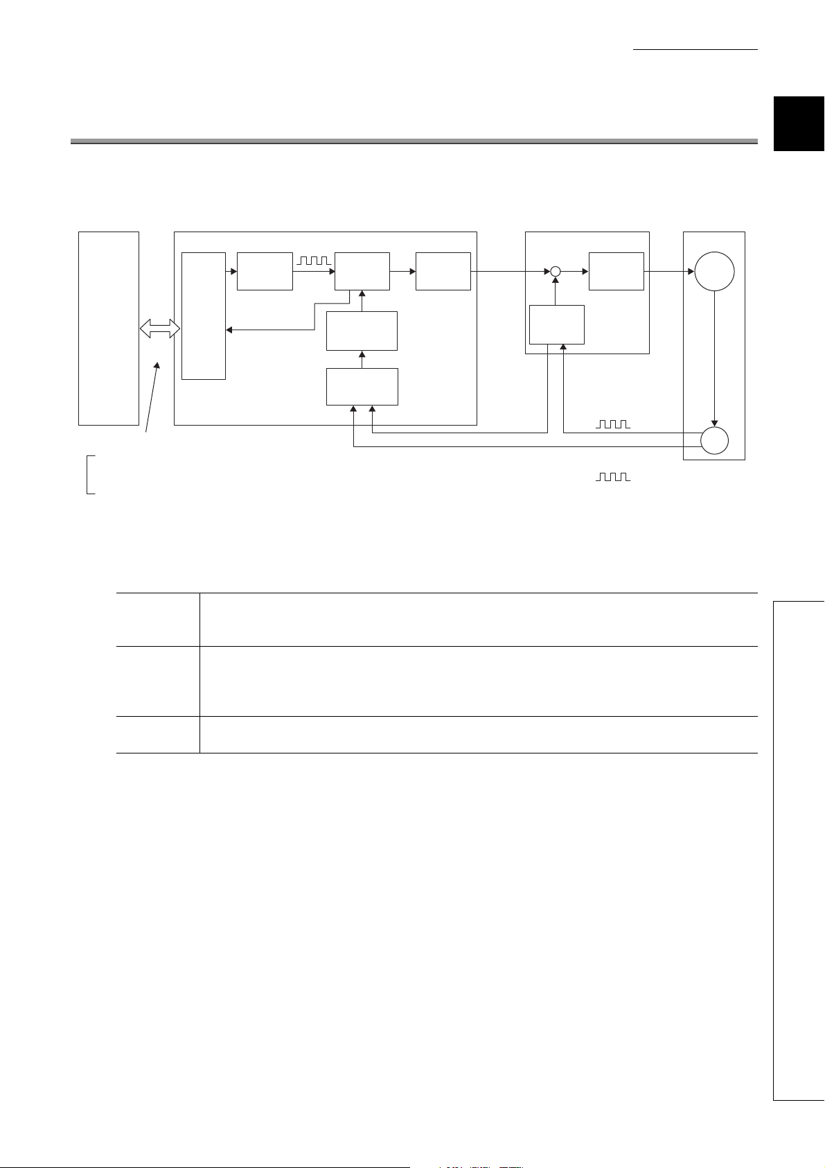
CHAPTER 1 OVERVIEW
Electronic
gear
Deviation
counter
D/A
converter
Multiplication
Servo
amplifier
Setting
data
Sequence
program
Command
pulses
Interface
CPU module
Parameter data
Positioning data
OPR parameters
Data writing/reading
Positioning module QD73A1
Analog
voltage
Speed
command
Drive unit Servomotor
Feedback pulses
Feedback pulses
*1
*2
M
PLG
*1
Current
value
Feedback pulses from the pulse generator (PLG) may be input to the QD73A1
via the drive unit
*1
or directly*2 depending on the servomotor to be used.
Check which method applies in the manual for the servomotor or drive unit to
be used.
Feedback pulse
addition/
subtraction setting
CHAPTER 1 OVERVIEW
The QD73A1 possesses a deviation counter and D/A converter inside as in the following figure.
1
A system with the QD73A1 operates as follows.
Once a command pulse train for positioning is output, pulses are accumulated in the deviation counter. The
Start
Operation
Stop
integrated value of pulses (accumulated pulses) is converted into DC analog voltage by a D/A converter, then
turns into a speed command to a servomotor. The speed command from a drive unit starts servomotor rotation.
Once the servomotor starts rotating, feedback pulses that are proportional to the number of rotations are
generated by a pulse generator (PLG) attached to the servomotor. The generated feedback pulses are
subtracted from the accumulated pulses in the deviation counter. The deviation counter continues to rotate the
servomotor, maintaining a constant amount of accumulated pulse.
Once the command pulse output from the QD73A1 stops, the accumulated pulses in the deviation counter
decrease, so does the speed. When there is no more accumulated pulse, the servomotor stops.
The rotation speed of a servomotor is proportional to command pulse frequency, while the rotation degree of the
servomotor is proportional to the output command pulse amount. By setting feed per pulse beforehand, analog voltage
that is proportional to the number of pulses in a pulse train is output, and a workpiece can be moved to the set position.
Note that pulse frequency defines the rotation speed of the servomotor (feedrate).
17
Page 20

1.1 Features
(1) Analog output type that possesses a deviation counter and D/A converter
inside
This module converts command pulse for positioning into analog voltage inside, then outputs a speed command
to a servo amplifier.
(2) Compatible with analog input servo amplifiers
A servo amplifier does not require an extra module to convert pulse input into analog voltage; a standard servo
amplifier can be used.
(3) Servomotor control using a high-resolution encoder
This module handles up to 1Mpulse/s of pulse input from an encoder. Servomotor control that uses high-speed
input pulse signals from a high-resolution encoder improves the accuracy of positioning.
(4) Four types of positioning method
The following control can be executed.
• Position control mode: positioning control and two-phase trapezoidal positioning control
• Speed-position control switch mode: speed-position control switchover and speed control
(5) Zero/gain adjustment through a sequence program
Zero/gain adjustment can be performed through a sequence program. Therefore, the adjustment can be
performed without using a switch or checking a LED, saving man-hour.
(Note that zero/gain adjustment can also be performed using switches on the front of the QD73A1.)
(6) Easy setting with GX works2
Sequence programming is reduced since initial settings and the auto refresh setting can be configured on the
screen. In addition, the setting status and operating status of the module can be checked easily.
18
Page 21
CHAPTER 1 OVERVIEW
Y2D
X11
X12
Y20
X20
X13
Y21 to Y23
X21 to X23
X14
X15
Y2C
Y24, Y25
Y26
Y27
X18
Y28
X19
Y29
X1A
Y2A
X16
X17
X1C
X1D
X1E, X1F
X1B
X10
X24
Y1A
X2A
Y1B
X2B
Y1C
X2C
X2D
Interface with
the CPU
module
External
interface
External
control
signals
PLG
Drive unit
PLC READY signal
QD73A1 READY signal
OPR request signal
OPR start signal
OPR start complete signal
OPR complete signal
Positioning start signal
Positioning start complete signal
BUSY signal
Positioning complete signal
Speed-position switching enable signal
JOG start signal
Speed-position mode restart signal
Stop signal
Error detection signal
Error reset signal
Overflow signal
Overflow reset signal
Underflow signal
Underflow reset signal
In-position signal
Excessive error signal
Near-point dog signal
External stop signal
Upper limit signal/Lower limit signal
Servo READY signal
WDT error, H/W error signal
Synchronization flag
Zero/gain adjustment data
writing request signal
Zero/gain adjustment data
writing complete flag
Zero/gain adjustment change request signal
Zero/gain adjustment change complete flag
Set value change request signal
Set value change complete flag
Operating status of the speed-position
control switch mode
Stop signal (STOP)
Near-point dog signal (DOG)
Upper limit signal (FLS)
Lower limit signal (RLS)
Speed-position switching command signal
(CHANGE)
Phase-Z pulse (Zero signal)
Phase-A pulse
Phase-B pulse
Servo READY signal (READY)
Servo ON signal (SVON)
CPU module
QD73A1
Analog voltage
Data writing/reading
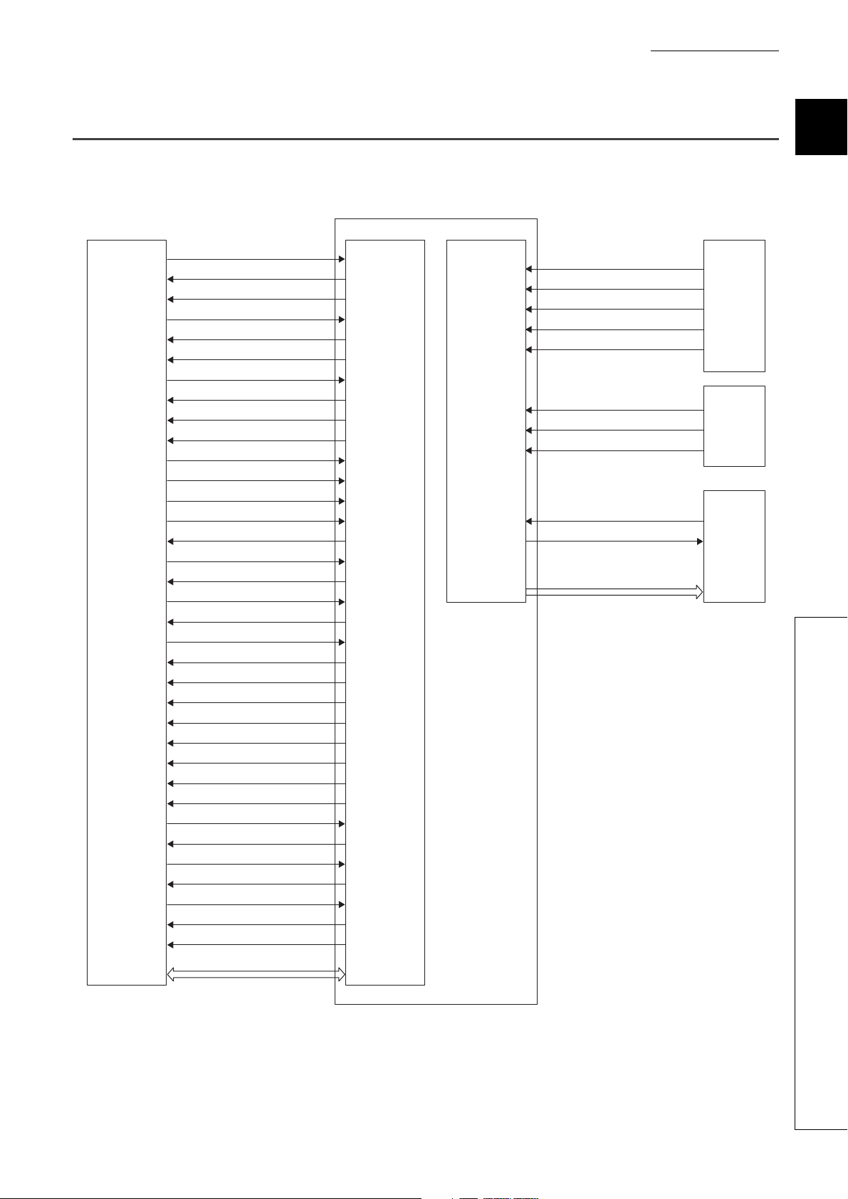
1.2 Signal Transmission Between the QD73A1 and Others
The following figure shows signal transmission between the QD73A1 and a CPU module, and a drive unit.
19
1
1.2 Signal Transmission Between the QD73A1 and Others
Page 22

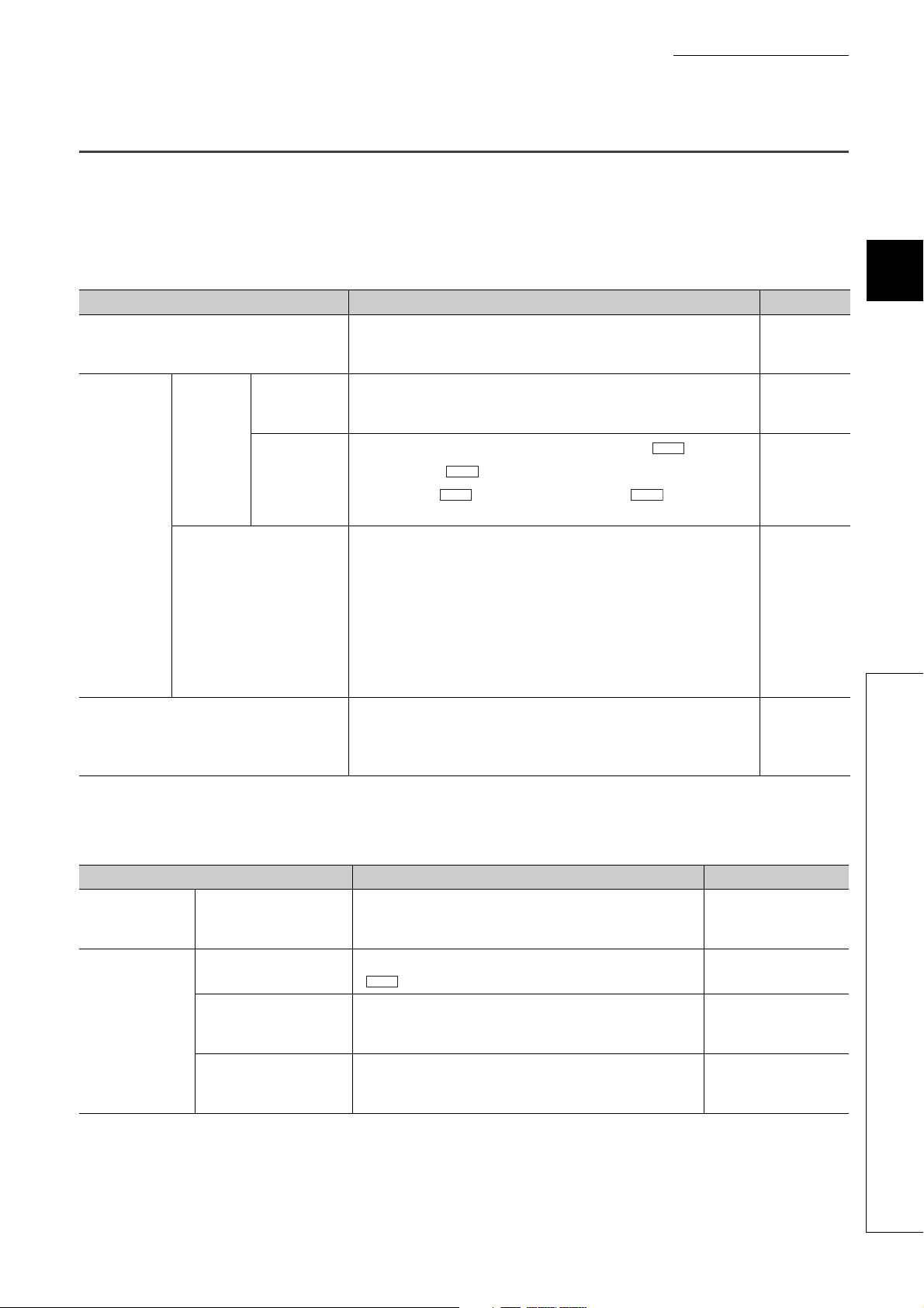
(1) Between the CPU module and the QD73A1
The CPU module and the QD73A1 transmit control signals and data to each other through the base unit.
Transmitted item Description Reference
Control signal
Data
Signals that indicate the QD73A1's status or
are related to commands are transmitted.
Data is written to or read from the buffer
memory in the QD73A1 by application
instructions of the CPU module.
Page 30, Section 3.4
Page 73, CHAPTER 5
(2) Between the drive unit and the QD73A1
Control signals are transmitted between the drive unit and the QD73A1, and speed commands (analog voltage)
are output from the QD73A1 to the drive unit.
For details, refer to the following.
Page 40, Section 3.5
20
Page 23

CHAPTER 2 SYSTEM CONFIGURATION
CHAPTER 2 SYSTEM CONFIGURATION
This chapter describes the system configuration of the QD73A1.
2.1 Applicable Systems
This section describes applicable systems.
(1) Applicable modules and base units, and number of mountable modules
For the applicable CPU modules and base units, and the number of mountable modules, refer to the user’s
manual for the CPU module used.
Note the following when mounting modules with the CPU module.
• The power supply capacity may become insufficient depending on the combination with other modules or the
number of mounted modules.
Select the power supply capacity according to the modules to be used.
If the power supply capacity is insufficient, change the combination of the modules.
• Mount the modules within the number of I/O points range of the CPU module.
Modules can be mounted on any slot within the number of available slots.
(a) When mounted on MELSECNET/H remote I/O station
For an applicable MELSECNET/H remote I/O station and base units, and the number of mountable modules,
refer to the Q Corresponding MELSECNET/H Network System Reference Manual (Remote I/O network).
2
2.1 Applicable Systems
(2) Multiple CPU system
The function version of the first released QD73A1 is B, and the module supports multiple CPU systems.
When using the QD73A1 in a multiple CPU system, refer to the following.
QCPU User's Manual (Multiple CPU System)
(a) Intelligent function module parameters
Write intelligent function module parameters to only the control CPU of the QD73A1.
(3) Online module change
The QD73A1 does not support online module change.
21
Page 24

(4) Applicable software packages
The following table lists systems that use the QD73A1 and applicable software packages.
A programming tool is required to use the QD73A1.
Item
GX Developer
Q00J/Q00/Q01CPU
Q02/Q02H/Q06H/Q12H/Q25HCPU
Q02PH/Q06PHCPU
Q12PH/Q25PHCPU
Q12PRH/Q25PRHCPU Redundant system Version 8.45X or later
Q00UJ/Q00U/Q01UCPU
Q02U/Q03UD/Q04UDH/Q06UDHCPU
Q10UDH/Q20UDHCPU
Q13UDH/Q26UDHCPU
Q03UDE/Q04UDEH/Q06UDEH/Q13UDEH/Q26
UDEHCPU
Q10UDEH/Q20UDEHCPU
CPU modules other than the above
When mounted on a MELSECNET/H remote I/O station Version 6 or later
Single CPU system Version 7 or later
Multiple CPU system Version 8 or later
Single CPU system Version 4 or later
Multiple CPU system Version 6 or later
Single CPU system
Multiple CPU system
Single CPU system
Multiple CPU system
Single CPU system
Multiple CPU system
Single CPU system
Multiple CPU system
Single CPU system
Multiple CPU system
Single CPU system
Multiple CPU system
Single CPU system
Multiple CPU system
Single CPU system
Multiple CPU system
Single CPU system
Multiple CPU system
Version 8.68W or later
Version 7.10L or later
Version 8.76E or later
Version 8.48A or later
Version 8.76E or later
Version 8.62Q or later
Version 8.68W or later
Version 8.76E or later
*1
N/A
Software version
GX Works2
Refer to the GX Works2
Version 1 Operating Manual
(Common).
*1 When using GX Developer, configure the initial settings and auto refresh settings with the sequence program.
PROGRAMMING ( Page 111, CHAPTER 7)
22
Page 25
CHAPTER 2 SYSTEM CONFIGURATION
14041000000000-B
Relevant regulation standards
Function version
Serial number (first five digits)
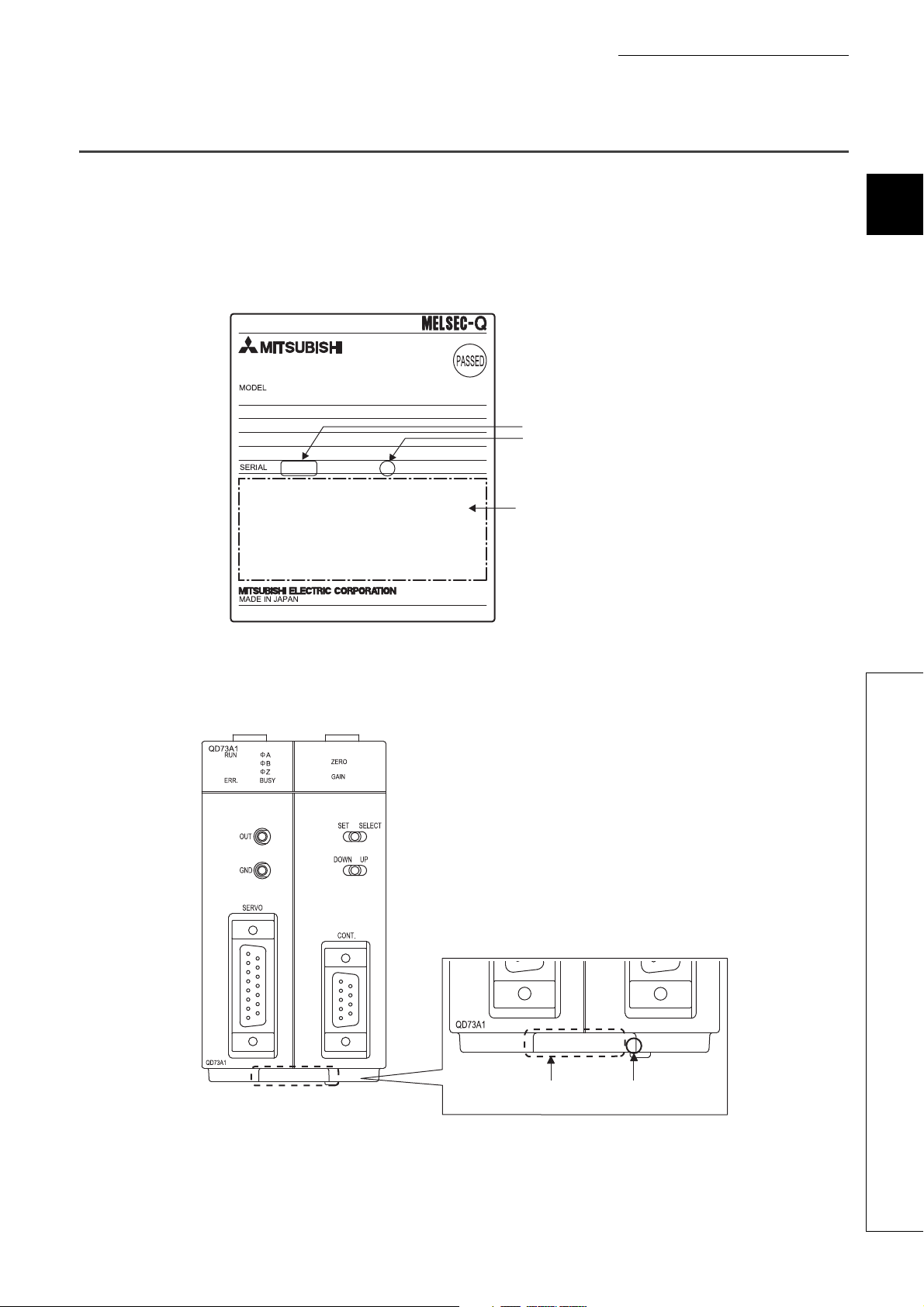
2.2 How to Check the Function Version and Serial Number
The function version and serial number of the QD73A1 can be checked on the rating plate, front part of the module, or
system monitor of the programming tool.
(1) Checking on the rating plate
The rating plate is on the side of the QD73A1.
2
(2) Checking on the front part (bottom part) of the module
The function version and serial number on the rating plate are also shown on the front part (bottom part) of the
module.
140410000000000-B
Serial No. Function version
2.2 How to Check the Function Version and Serial Number
23
Page 26
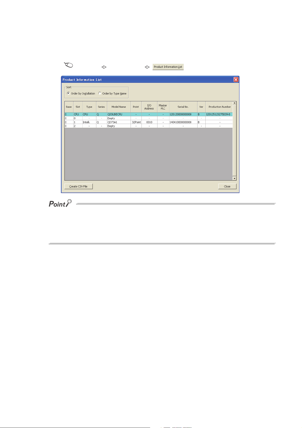
(3) Checking on the system monitor
The function version and serial number can be checked on the "Product Information List" window.
[Diagnostics] [System Monitor...] button
● The serial number displayed on the product information list of a programming tool may differ from that on the rating plate
and on the front part of the module.
• The serial number on the rating plate and front part of the module indicates the management information of the
product.
• The serial number displayed on the product information list of a programming tool indicates the function
information of the product. The function information of the product is updated when a new function is added.
24
Page 27

CHAPTER 3 SPECIFICATIONS
CHAPTER 3 SPECIFICATIONS
This chapter describes performance specifications, I/O signals from/to the CPU module, and buffer memory
specifications of the QD73A1.
For general specifications of the QD73A1, refer to the following.
QCPU User's Manual (Hardware Design, Maintenance and Inspection)
3.1 Performance Specifications
The following table lists performance specifications of the QD73A1.
Item Specifications
Number of occupied I/O points 48 points (I/O assignment: empty 16 points and intelligent 32 points)
Number of control axes 1 axis
Positioning data
Positioning
Speed command output 0 to ±10VDC (Adjustable to set in the range of ±5 to ±10VDC)
Positioning feedback
pulse input
OPR control
JOG operation JOG operation can be started by inputting a JOG start signal.
M function None
Internal current consumption (5VDC) 0.52A
External supply voltage/current terminal block No external power supply
External dimensions 98(H)mm × 55.2(W)mm × 90(D)mm
Weight 0.20kg
Starting time
(from a start request to analog output start)
Capacity 1 data
Setting method Sequence program
Mode
Position control mode: Selectable from absolute system or incremental
System
Speed-position control switch mode: Incremental system
Position command -2147483648 to 2147483647 (pulse) (signed 32-bit binary)
Speed command 1 to 4000000 (pulse/s)
Acceleration Automatic trapezoidal acceleration/deceleration
Automatic
acceleration/deceleration time
In-position range 1 to 20479 (pulse)
Backlash compensation None
Error correction function None
Pulse frequency
Connectable encoder type Open collector, TTL, or differential output
Multiplication setting The number of input feedback pulses can be multiplied by 4, 2, 1, or 1/2.
An OPR method and OPR direction can be set with the switch setting.
Absolute system: 1.2ms (same for two-phase trapezoidal positioning)
Incremental system: 1.2ms (same for two-phase trapezoidal positioning)
Position control mode
Speed-position control switch mode
system
Acceleration time: 2 to 9999 (ms)
Deceleration time: 2 to 9999 (ms)
Open collector: 200kpulse/s
TTL: 200kpulse/s
Differential output: 1Mpulse/s
With OP address change
JOG operation: 1.2ms
OPR (near-point dog method): 1.2ms
OPR (count method): 1.2ms
3
3.1 Performance Specifications
25
Page 28
3.2 Number of Parameter Settings
Set initial settings and auto refresh settings of the QD73A1 so that the number of parameters, including those of other
intelligent function modules, does not exceed the number of parameters that can be set in the CPU module.
For the maximum number of parameters that can be set in the CPU module, refer to the following.
QCPU User's Manual (Hardware Design, Maintenance and Inspection)
(1) Number of QD73A1 parameters
For a QD73A1, the following number of parameters can be set.
Initial setting Auto refresh setting
45
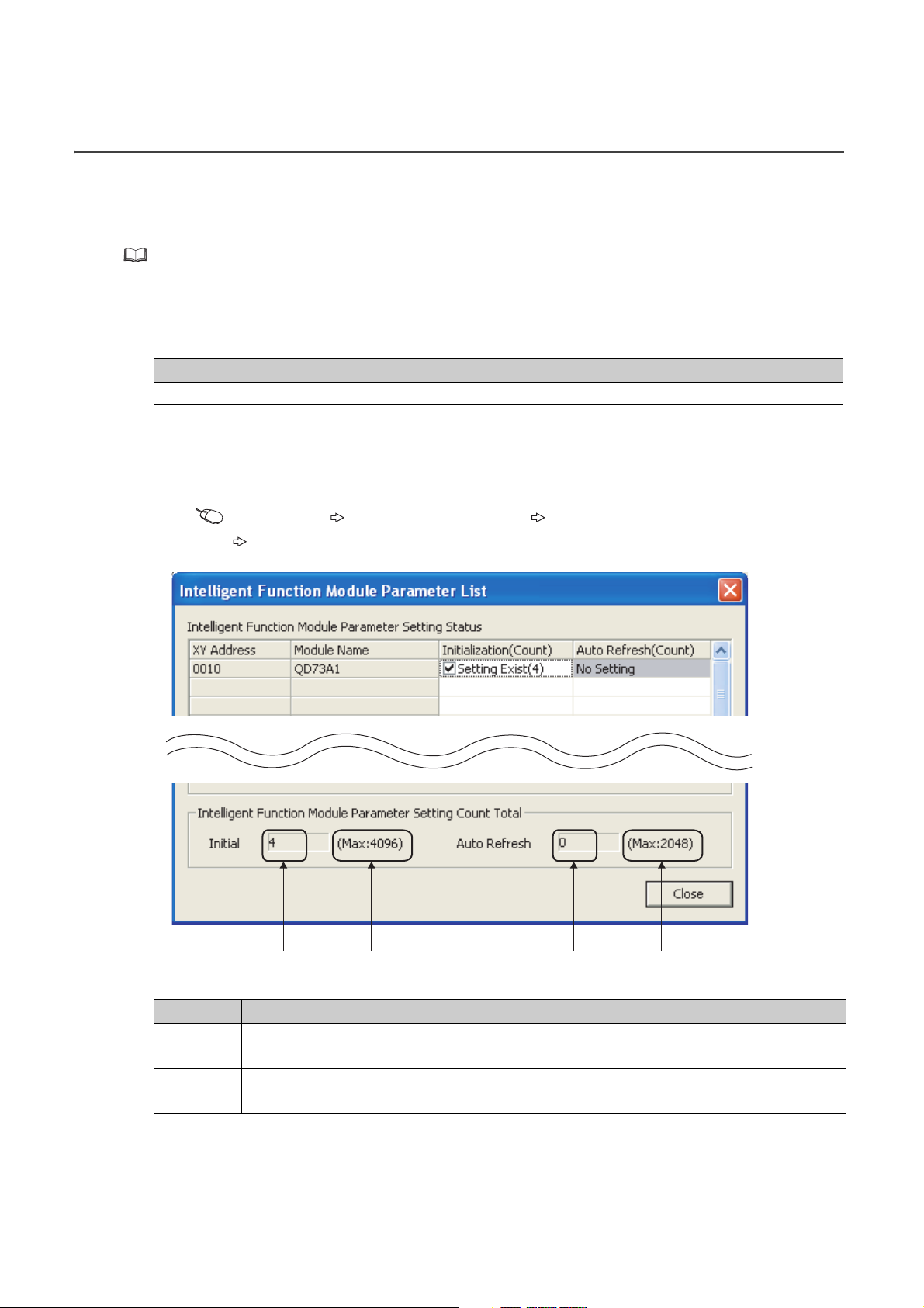
(2) Checking method
The maximum number of parameter settings and the number of parameter settings set for the intelligent function
module can be checked on the following.
Project window [Intelligent Function Module] Right-click
[Intelligent Function Module Parameter List...]
26
1) 2) 3) 4)
No. Description
1) The total number of parameters in initial settings checked on the window
2) The maximum number of parameter settings in initial settings
3) The total number of parameters in the auto refresh setting checked on the window
4) The maximum number of parameter settings in the auto refresh setting
Page 29
3.3 List of Functions
Da.4
Da.5
Pr.5
This section introduces the functions of the QD73A1.
(1) Main functions
Major positioning functions are as follows.
Item Description Reference
A workpiece is returned to an original point following an OPR start
OPR control
Major
positioning
control
JOG operation
Positioning
control
Position
control
mode
Speed-position control switch
mode
Two-phase
trapezoidal
positioning
control
command, and the current value is corrected as an OP address after the
completion of OPR.
Positioning is executed from the current position to a specified position at
a specified speed.
Positioning is executed to the address specified with " Positioning
address P1" at " Positioning speed V1", then to the address
specified with " Positioning address P2" at " Positioning
speed V2" by one positioning start signal.
Operation starts according to the positioning speed set beforehand by
one positioning start signal, then the operation switches to position
control by Speed-position switching command signal (CHANGE).
If the operation stopped by Stop signal after the input of Speed-position
switching command signal (CHANGE), the positioning can be continued
by requesting a restart.
In addition, the positioning address (movement amount) can be changed
if it is before the input of Speed-position switching command signal
(CHANGE).
Positioning is executed in the specified direction at specified speed while
a JOG operation command is on. Turning on the signal starts operation
at a specified speed and speed control operation can be continued until a
stop signal is input.
Da.3
CHAPTER 3 SPECIFICATIONS
Page 178,
CHAPTER 8
Page 191,
Section 9.6.1
(1)
Da.2
Page 192,
Section 9.6.1
(2)
Page 195,
Section 9.6.2
Page 200,
CHAPTER 10
3
3.3 List of Functions
(2) Sub functions
Sub functions compensate or limit control, or add functions at the execution of major positioning functions.
Functions to
compensate
control
Functions to limit
control
Item Description Reference
Electronic gear function
Speed limit function
Stroke limit function
Upper limit switch
(FLS)/lower limit switch
(RLS) function
This function controls moving distance and speed by
multiplying command pulse output of the QD73A1.
This function limits command speed to the value set in
" Speed limit value".
This function controls operation not to execute positioning
when a command that moves the workpiece outside the
specified stroke limit range is given.
This function decelerates and stops operation according to the
detection on limit switches placed at the upper and lower
stroke limits.
Page 209, Section 11.1
Page 211, Section 11.2
Page 213, Section 11.3
Page 215, Section 11.4
27
Page 30

Functions to
change control
details
Other functions
Item Description Reference
Current value change
function
Speed change function
Deviation counter clear
function
In-position function
Multiplication setting
Accumulated pulse error
detection function
This function changes the value set in " Current feed
value" to a specified value.
This function changes speed during major positioning control
or JOG operation.
This function clears the accumulated pulses in the deviation
counter. When the servomotor power was turned off due to an
emergency stop during positioning, clearing the accumulated
pulses in the deviation counter prevents servomotor rotation
at power recovery.
This function turns on In-position signal (X16) while the
accumulated pulse amount in the deviation counter is within
the specified in-position range (1 to 20479pulse). In-position
signal (X16) can be used as the signal right before positioning
completion.
This function multiplies the feedback pulse frequency from the
pulse generator by 4, 2, 1, or 1/2.
This function outputs an alert and immediately stops the
positioning when the accumulated pulses reached the amount
specified by the user before the pulses exceed the amount set
in "Accumulated pulse setting" in the switch setting and an
excessive error occurs.
Md.1
Page 217, Section 11.5
Page 218, Section 11.6
Page 220, Section 11.7
Page 221, Section 11.8
Page 104, Section 6.2.3
Page 223, Section 11.9
(3) Common functions
Common functions can be used regardless of control method when necessary.
Item Description Reference
Zero/gain adjustment This function adjusts analog output voltage. Page 59, Section 4.5
This function monitors the module information, switch setting
Module status monitor function
Error history function
Module error collection function
Error clear function This function allows the user to clear errors on the system monitor.
information, and external I/O signal information. The module's
detailed information can be displayed on the system monitor of GX
Works2.
This function monitors the QD73A1's error history stored in the
buffer memory.
This function reports errors that occurred in the QD73A1 to the CPU
module. The error information is held in the CPU module memory as
a module error history.
Page 236, Section
13.1
Page 238, Section
13.2
Page 239, Section
13.3
Page 240, Section
13.4
28
Page 31

(4) Combination of main function and sub function
: Always used together, : Can be used together, ×: Cannot be used together
Functions to
compensate
control
Item
Functions to limit
control
CHAPTER 3 SPECIFICATIONS
Functions to change
control details
Other functions
3
Electronic gear function
OPR control ×××
Position
Major
positioning
control
JOG operation ××
control
mode
Speed-position control switch
mode
Positioning control × ×
Two-phase
trapezoidal
positioning control
Speed limit function
Stroke limit function
Upper limit switch (FLS)/
Current value change function
lower limit switch (RLS) function
××
××
Speed change function
Deviation counter clear function
In-position function
Multiplication setting
detection function
Accumulated pulse error
3.3 List of Functions
29
Page 32

3.4 I/O Signals from/to the CPU Module
This section describes I/O signals of the QD73A1.
3.4.1 I/O signal list
This section describes I/O signal assignment and use of each signal.
The first half of the I/O assignment is empty 16 points, and the second half is intelligent 32 points. When the module is
mounted on the slot No.0 and 1 of a main base unit, the device No.Xn0 becomes X10. Although, when the slot No.0 is
set as empty 0 point in the I/O assignment setting of GX Works2, the device No.Xn0 becomes X0 (n=0).
Device numbers used in this manual are for the case when the QD73A1 is mounted on the slot No.0 and 1 and when
the slot No.0 is empty 16 points.
(1) Input signal list
Input signal (CPU module QD73A1) Input signal (CPU module QD73A1)
Device No. Signal name Device No. Signal name
X10 WDT error, H/W error signal X20 OPR start complete signal
X11 QD73A1 READY signal X21 Absolute positioning start complete signal
X12 OPR request signal X22 Forward start complete signal
X13 OPR complete signal X23 Reverse start complete signal
X14 BUSY signal X24 Synchronization flag
X15 Positioning complete signal X25
X16 In-position signal X26
X17 Excessive error signal X27
X18 Error detection signal X28
X19 Overflow signal X29
X1A Underflow signal X2A
X1B Servo READY signal X2B Zero/gain adjustment change complete flag
X1C Near-point dog signal X2C Set value change complete flag
X1D External stop signal X2D
X1E Upper limit signal X2E
X1F Lower limit signal X2F
Use prohibited
Zero/gain adjustment data writing complete
flag
Operating status of the speed-position
control switch mode
Use prohibited
30
If a "Use prohibited" area is turned on/off through a sequence program, the QD73A1's function cannot be guaranteed.
Page 33

CHAPTER 3 SPECIFICATIONS
(2) Output signal list
Output signal (CPU module QD73A1) Output signal (CPU module QD73A1)
Device No. Signal name Device No. Signal name
Y10
Y11 Y21 Absolute positioning start signal
Y12 Y22 Forward start signal
Y13 Y23 Reverse start signal
Y14 Y24 Forward JOG start signal
Y15 Y25 Reverse JOG start signal
Y16 Y26 Speed-position mode restart signal
Y17 Y27 Stop signal
Y18 Y28 Error reset signal
Y19 Y29 Overflow reset signal
Y1A
Y1B
Y1C Set value change request signal Y2C Speed-position switching enable signal
Y1D
Y1E Y2E
Y1F Y2F
Use prohibited
Zero/gain adjustment data writing request
signal
Zero/gain adjustment change request
signal
Use prohibited
Y20 OPR start signal
Y2A Underflow reset signal
Y2B Use prohibited
Y2D PLC READY signal
Use prohibited
3
If a "Use prohibited" area is turned on/off through a sequence program, the QD73A1's function cannot be guaranteed.
3.4.1 I/O signal list
3.4 I/O Signals from/to the CPU Module
31
Page 34

3.4.2 Details of input signals
PLC READY signal (Y2D)
QD73A1 READY signal (X11)
OFF
ON
OFF
ON
Executed by the QD73A1
(1) WDT error, H/W error signal (X10)
This signal turns on when a watchdog timer error is detected through the self-diagnostic function of the QD73A1.
In this case, Servo ON signal (SVON) turns off and analog output becomes 0.
(2) QD73A1 READY signal (X11)
When PLC READY signal (Y2D) is turned on through a sequence program, fixed parameters are checked and
this signal turns on.
When PLC READY signal (Y2D) is turned off, this signal turns off.
Use this signal as an interlock in sequence programs.
(3) OPR request signal (X12)
This signal turns on at any of the following timing.
• When the power is turned on
• When the CPU module was reset
• When OPR starts
• When Servo READY signal (READY) turns off while BUSY signal (X14) is on
• When Servo READY signal (READY) turns off while BUSY signal (X14) is off
(only when "0: Clear the deviation counter when the servo ready signal is OFF." is selected for "Deviation
counter clear setting" in the switch setting)
This signal turns off when OPR is completed.
When PLC READY signal (Y2D) is turned on (rising edge), this signal does not turn on.
(4) OPR complete signal (X13)
This signal turns on when OPR is completed.
This signal does not turn on if operation stopped during OPR.
This signal turns off when JOG operation or major positioning control is started.
In the count method, this signal turns off when OPR starts.
This signal turns off when Servo READY signal (READY) turns off (only when "0: Clear the deviation counter
when the servo ready signal is OFF." is selected for "Deviation counter clear setting" in the switch setting)
(5) BUSY signal (X14)
This signal turns on when major positioning control, JOG operation, or OPR starts.
This signal turns off when command pulse output is completed.
If positioning is started while BUSY signal (X14) is on, the error "BUSY signal ON at start" (error code: 81) occurs.
32
Page 35

CHAPTER 3 SPECIFICATIONS
Pr.8
Md.2
Md.1
Excessive error signal (X17)
PLC READY signal (Y2D)
OFF
ON
OFF
ON
Executed by the QD73A1
(6) Positioning complete signal (X15)
This signal turns on when major positioning control is completed (completion of command pulse output).
This signal turns off when the next positioning (major positioning control, OPR, or JOG operation) starts.
If major positioning control was cancelled during its operation, this signal does not turn on.
For the operation in case of cancellation of major positioning control, refer to the following.
Page 230, Section 12.1
(7) In-position signal (X16)
This signal turns on while the accumulated pulse amount in the deviation counter is within the set range of
" In-position range" (1 to
This signal turns off when positioning starts.
Accumulated pulses
±20479) after deceleration started.
In-position set values
3
t
In-position signal
(X16)
Accumulated pulse amount are checked being compared with " In-position range" at the following timing.
ON
OFF
AA
A: In-position range
Pr.8
• When the power is turned on
• When automatic deceleration starts in positioning, and thereafter
• When a JOG start signal was turned off and deceleration starts in JOG operation, and thereafter
• When the near-point dog turned on and deceleration to the creep speed starts in OPR, and thereafter
(8) Excessive error signal (X17)
This signal turns on when accumulated pulse amount exceeds the accumulated pulse setting range.
In this case, the QD73A1's status is as follows.
• Analog output voltage: 0V
• Accumulated pulse: Reset to 0
• Servo ON signal (SVON): OFF
• Actual current value = Current feed value
When PLC READY signal (Y2D) is turned on, this signal turns off.
3.4 I/O Signals from/to the CPU Module
3.4.2 Details of input signals
Even if this signal turns on, Error detection signal (X18) does not turn on.
For the accumulated pulse setting range, refer to the following.
Page 102, Section 6.2.2
33
Page 36

(9) Error detection signal (X18)
Error detection signal (X18)
Error reset signal (Y28)
OFF
ON
OFF
ON
Executed by the QD73A1
Md.1
Overflow signal (X19)
Overflow reset signal (Y29)
OFF
ON
OFF
ON
Executed by the QD73A1
Md.1
Md.1
When a major or minor error occurs, the corresponding error code is stored in the buffer memory, and this signal
turns on.
When Error reset signal (Y28) is turned on, this signal turns off.
(10)Overflow signal (X19)
This signal turns on when " Current feed value" exceeds 2147483647.
When Overflow reset signal (Y29) is turned on, this signal turns off.
In case of an overflow, " Current feed value" changes as follows: 2147483647 -2147483648
(11)Underflow signal (X1A)
This signal turns on when " Current feed value" becomes less than -2147483648.
When Underflow reset signal (Y2A) is turned on, this signal turns off.
Underflow reset signal (Y2A)
In case of an underflow, " Current feed value" changes as follows: -2147483648 2147483647
Md.1
Underflow signal (X1A)
ON
OFF
ON
OFF
Executed by the QD73A1
(12)Servo READY signal (X1B)
This signal indicates the on/off status of Servo READY signal (READY).
(13)Near-point dog signal (X1C)
This signal indicates the on/off status of Near-point dog signal (DOG).
(14)External stop signal (X1D)
This signal indicates the on/off status of Stop signal (STOP).
(15)Upper limit signal (X1E)
(16)Lower limit signal (X1F)
34
This signal indicates the on/off status of Upper limit signal (FLS).
This signal indicates the on/off status of Lower limit signal (RLS).
Page 37

CHAPTER 3 SPECIFICATIONS
(17)OPR start complete signal (X20)
This signal turns on when OPR process starts after OPR start signal (Y20) was turned on.
When OPR start signal (Y20) is turned off after the start of OPR, this signal turns off.
(18)Absolute positioning start complete signal (X21)
This signal turns on when positioning process starts after Absolute positioning start signal (Y21) was turned on.
When Absolute positioning start signal (Y21) is turned off after the start of the positioning, this signal turns off.
(19)Forward start complete signal (X22)
This signal turns on when positioning process starts after Forward start signal (Y22) was turned on.
When Forward start signal (Y22) is turned off after the start of the positioning, this signal turns off.
(20)Reverse start complete signal (X23)
This signal turns on when positioning process starts after Reverse start signal (Y23) was turned on.
When Reverse start signal (Y23) is turned off after the start of the positioning, this signal turns off.
3
(21)Synchronization flag (X24)
This signal turns on when the CPU module becomes accessible to the QD73A1 after the power was turned off
then on, or after the CPU module was reset.
When the module synchronization setting of the CPU module is set to asynchronous, use this signal as an
interlock to access the QD73A1 from a sequence program.
(22)Zero/gain adjustment data writing complete flag (X2A)
This signal turns on when zero/gain adjustment value writing to the QD73A1 is completed after Zero/gain
adjustment data writing request signal (Y1A) was turned on.
When Zero/gain adjustment data writing request signal (Y1A) is turned off, this signal turns off.
ON
Zero/gain adjustment data
writing complete flag (X2A)
Zero/gain adjustment data
writing request signal (Y1A)
Use this signal as an interlock condition to turn on/off Zero/gain adjustment data writing request signal (Y1A)
when writing the zero/gain adjustment value to the QD73A1.
For details on zero/gain adjustment, refer to the following.
Page 59, Section 4.5
OFF
ON
OFF
Executed in a sequence program
Executed by the QD73A1
3.4 I/O Signals from/to the CPU Module
3.4.2 Details of input signals
35
Page 38

(23)Zero/gain adjustment change complete flag (X2B)
Zero/gain adjustment change
complete flag (X2B)
Zero/gain adjustment change
request signal (Y1B)
OFF
ON
OFF
ON
Zero/gain adjustment
specification
Executed in a sequence program
Executed by the QD73A1
Cd.10
This signal turns on when zero adjustment and gain adjustment were switched after Zero/gain adjustment
change request signal (Y1B) was turned on.
When Zero/gain adjustment change request signal (Y1B) is turned off, this signal turns off.
Use this signal as an interlock condition to turn on/off Zero/gain adjustment change request signal (Y1B) when
changing " Zero/gain adjustment specification".
Cd.10
For details on zero/gain adjustment, refer to the following.
Page 59, Section 4.5
(24)Set value change complete flag (X2C)
This signal turns on when the analog output value of zero/gain adjustment was changed after Set value change
request signal (Y1C) was turned on.
When Set value change request signal (Y1C) is turned off, this signal turns off.
ON
Set value change complete flag
(X2C)
Set value change request signal
(Y1C)
OFF
ON
OFF
Executed in a sequence program
Executed by the QD73A1
Use this signal as an interlock condition to turn on/off Set value change request signal (Y1C) when performing
zero/gain adjustment.
For details on zero/gain adjustment, refer to the following.
Page 59, Section 4.5
(25)Operating status of the speed-position control switch mode (X2D)
This signal indicates the operating status in the speed-position control switch mode.
This signal is on during speed control.
This signal is off during position control.
36
Page 39

3.4.3 Details of output signals
Cd.11
(1) Zero/gain adjustment data writing request signal (Y1A)
Turn on this signal to write the zero/gain adjustment value to the QD73A1.
For the on/off timing of this signal, refer to the detail of Zero/gain adjustment data writing complete flag (X2A).
( Page 35, Section 3.4.2 (22))
For details on zero/gain adjustment, refer to the following.
Page 59, Section 4.5
(2) Zero/gain adjustment change request signal (Y1B)
Turn on this signal to change zero adjustment and gain adjustment.
For the on/off timing of this signal, refer to the detail of Zero/gain adjustment change complete flag (X2B).
( Page 36, Section 3.4.2 (23))
For details on zero/gain adjustment, refer to the following.
Page 59, Section 4.5
CHAPTER 3 SPECIFICATIONS
3
(3) Set value change request signal (Y1C)
Turn on/off this signal to increase/decrease the analog output value at zero/gain adjustment.
The analog output is increased/decreased according to the value set in " Zero/gain adjustment value
specification".
For the on/off timing of this signal, refer to the detail of Set value change complete flag (X2C). ( Page 36,
Section 3.4.2 (24))
For details on zero/gain adjustment, refer to the following.
Page 59, Section 4.5
(4) OPR start signal (Y20)
Turn on this signal to start OPR.
(5) Absolute positioning start signal (Y21)
Turn on this signal to start absolute system positioning (position control mode).
(6) Forward start signal (Y22)
Turn on this signal to start positioning in the address increasing direction.
The following table describes the consequence of turning on this signal for each type of positioning (major
positioning control).
3.4 I/O Signals from/to the CPU Module
3.4.3 Details of output signals
Major positioning control Consequence of turning on Forward start signal (Y22)
Positioning control
Position control mode
Speed-position control switch mode Starts in the address increasing direction
Two-phase trapezoidal
positioning control
Starts in the address increasing direction (incremental system)
37
Page 40

(7) Reverse start signal (Y23)
Md.3
Md.4
Turn on this signal to start positioning in the address decreasing direction.
The following table describes the consequence of turning on this signal for each type of positioning (major
positioning control).
Major positioning control Consequence of turning on Reverse start signal (Y23)
Positioning control
Position control mode
Speed-position control switch mode Starts in the address decreasing direction
Two-phase trapezoidal
positioning control
Starts in the address decreasing direction (incremental system)
(8) Forward JOG start signal (Y24)
Turn on this signal to start JOG operation in the address increasing direction.
The JOG operation continues while this signal is on.
The JOG operation decelerates and stops when this signal is turned off.
(9) Reverse JOG start signal (Y25)
Turn on this signal to start JOG operation in the address decreasing direction.
The JOG operation continues while this signal is on.
The JOG operation decelerates and stops when this signal is turned off.
(10)Speed-position mode restart signal (Y26)
Turn on this signal to restart positioning if it stopped due to Stop signal in the speed-position control switch mode.
(11)Stop signal (Y27)
Turn on this signal to decelerate and stop OPR operation, major positioning operation, or JOG operation.
If this signal is turned on during OPR, Error detection signal (X18) turns on.
(12)Error reset signal (Y28)
Turn on this signal to clear the following buffer memory data to 0 when Error detection signal (X18) is on.
• Error code (ERR.1)
• Error code (ERR.2)
When this signal is turned on, Error detection signal (X18) turns off.
(13)Overflow reset signal (Y29)
Turn on this signal to turn off Overflow signal (X19) when it is on.
For the on/off timing of this signal, refer to the detail of Overflow signal (X19). ( Page 34, Section 3.4.2 (10))
38
Page 41

CHAPTER 3 SPECIFICATIONS
(14)Underflow reset signal (Y2A)
Turn on this signal to turn off Underflow signal (X1A) when it is on.
For the on/off timing of this signal, refer to the detail of Underflow signal (X1A). ( Page 34, Section 3.4.2 (11))
(15)Speed-position switching enable signal (Y2C)
Use this signal to enable/disable Speed-position switching command signal (CHANGE) in the speed-position
control switch mode.
Turn on this signal to enable Speed-position switching command signal (CHANGE). Turn off this signal to disable
Speed-position switching command signal (CHANGE).
(16)PLC READY signal (Y2D)
This signal notifies the QD73A1 that the CPU module is operating normally.
This signal needs to be turned on beforehand to start OPR, major positioning, or JOG operation.
This signal needs to be turned off beforehand to write fixed parameters and OPR parameters.
When this signal is turned on, the QD73A1 performs the following.
• 1: Checking fixed parameters
• 2: Turning on QD73A1 READY signal (X11)
• 3: Turning off Excessive error signal (X17) when it is on
When this signal is turned off while BUSY signal (X14) is on, the QD73A1 processes a deceleration stop.
When this signal is turned on while BUSY signal (X14) is on, the QD73A1 does not perform the operations 1 to 3
above.
Deceleration followed by PLC
READY signal (Y2D) OFF
Even when PLC READY signal
(Y2D) is turned on, the operations
1 to 3 are not performed.
3
3.4 I/O Signals from/to the CPU Module
3.4.3 Details of output signals
PLC READY signal (Y2D)
QD73A1 READY signal (X11)
BUSY signal (X14)
ON
ON
OFF
ON
OFF
Executed by the QD73A1
39
Page 42

3.5 Specifications of I/O Interfaces with External Devices
5 s or more
2.5 s
or more
2.5 s
or more
1 s or more
0.5 s
or more
0.5 s
or more
This section describes I/O interfaces between the QD73A1 and external devices.
3.5.1 Electrical specifications of I/O signals
This section describes electrical specifications of I/O interfaces between the QD73A1 and external devices.
(1) Input specifications
Signal name
Supply power Input common
Servo READY signal (READY)
Stop signal (STOP)
Near-point dog signal (DOG)
Upper limit signal (FLS)
Lower limit signal (RLS)
Speed-position switching command
signal (CHANGE)
(Open collector method)
Phase-A feedback pulse (PULSE A)
Phase-B feedback pulse (PULSE B)
Phase-Z feedback pulse (PULSE Z)
(TTL method)
Phase-A feedback pulse (PULSE A)
Phase-B feedback pulse (PULSE B)
Phase-Z feedback pulse (PULSE Z)
(Differential output method)
Phase-A feedback pulse (PULSE A)
Phase-B feedback pulse (PULSE B)
Phase-Z feedback pulse (PULSE Z)
Volta ge
range/Current
consumption
5 to 24VDC/
Max.60mA
4.75 to 26.4VDC
10.8 to 14VDC
4.5 to 5.5VDC
ON
voltage
3V or
higher
4V or
higher
2.8V or
higher
EIA standard
RS-422-A differential line receiver
(Equivalent of AM26LS32 (Manufactured by Texas
Instruments Inc.))
ON
current
2.5mA or
higher
2.7mA or
higher
OFF
voltage
1V or lower
1V or lower
0.8V or
lower
OFF
current
0.1mA or
lower
0.1mA or
lower
Pulse
frequency
200kpulse/s or
*1
less
200kpulse/s or
*1
less
1Mpulse/s or
*1
less
*1 The following table shows the pulse width and phase difference depending on pulse frequency.
Pulse frequency Pulse width (duty ratio: 50%) Phase difference
Phase A
200kpulse/s or less
Phase B
Phase A
1Mpulse/s or less
Phase B
1.25 s or more
0.25 s or more
40
When the phase A leads the
phase B, the positioning
address (current value)
increases.
Page 43

(2) Output specifications
Signal name
Servo ON signal (SVON) Open collector
Speed command signal
(analog signal)
*1 The load current of Servo ON signal (SVON) is 30mA at the maximum. When using a miniature relay, take the load
current into consideration.
Analog output
voltage/current
0 to ±10VDC/10mA
Output method
Load
voltage
4.75 to
26.4VDC
Load
current
Max.30mA
CHAPTER 3 SPECIFICATIONS
Max.
voltage
drop at
current at OFF
ON
1.0V or
*1
lower
0.1mA or lower
Leakage
3
3.5 Specifications of I/O Interfaces with External Devices
3.5.1 Electrical specifications of I/O signals
41
Page 44

3.5.2 Signal layout for external device connectors
9
1
2
3
4
5
6
7
8
The following table shows signal layouts on external device connectors.
Connector
name
CONT.
SERVO
Pin arrangement Pin number Signal name
1 Near-point dog signal (DOG)
2Empty
3Empty
4Empty
5 Power supply (5 to 24V)
6 Lower limit signal (RLS)
7 Upper limit signal (FLS)
8 Speed-position switching command signal (CHANGE)
Viewed from the front
of the module
1
9
2
10
3
11
4
12
5
13
6
14
7
15
8
Viewed from the front
of the module
9 Stop signal (STOP)
1 Servo READY signal (READY) (+ side)
2 Servo READY signal (READY) (- side)
3 Servo ON signal (SVON) (+ side)
4 Servo ON signal (SVON) (- side)
5 Phase-B feedback pulse (PULSE B) (+ side)
6 Phase-Z feedback pulse (PULSE Z) (+ side)
7 Phase-Z feedback pulse (PULSE Z) (- side)
8Empty
9 Analog GND
10 Phase-B feedback pulse (PULSE B) (- side)
11 Phase-A feedback pulse (PULSE A) (- side)
12 Empty
13 Phase-A feedback pulse (PULSE A) (+ side)
14 Speed command signal (- side)
15 Speed command signal (+ side)
42
Page 45

CHAPTER 3 SPECIFICATIONS
Phase A
Phase B
Positioning
address +1+1+1 +1+1 +1+1+1
[When increased]
Phase A
Phase B
Positioning
address -1 -1 -1 -1 -1 -1 -1 -1
[When decreased]
3.5.3 List of I/O signal details
This section describes details of signals that are input or output through external device connectors on the QD73A1.
Signal name
Phase-A feedback pulse (PULSE A)
(+ side)
Phase-B feedback pulse (PULSE B)
(+ side)
Phase-Z feedback pulse (PULSE Z)
(+ side)
Phase-A feedback pulse (PULSE A)
(- side)
Phase-B feedback pulse (PULSE B)
(- side)
Phase-Z feedback pulse (PULSE Z)
(- side)
Analog GND 9
Upper limit signal (FLS)
Lower limit signal (RLS) 6
Near-point dog signal (DOG) 1
Stop signal (STOP) 9
Speed-position switching command
signal (CHANGE)
Power supply (5 to 24V) 5
Connector
name
SERVO
CONT.
Pin
number
13
5
6
11
10
7
7
8
Input this signal to switch control during the speed-position control
switch mode.
This power supply is common to the following signals.
Signal detail
• Feedback pulse signals of encoder's phases A, B, and Z are
input.
• When the phase A leads the phase B, the positioning address
increases at the rising and falling edges of each phase.
• When the phase B leads the phase A, the positioning address
decreases at the rising and falling edges of each phase.
• This signal is input from the limit switch placed at stroke upper
limit position.
• As this signal turns off, positioning stops.
• This signal is input from the limit switch placed at stroke lower
limit position.
• As this signal turns off, positioning stops.
• This signal is used for detection on the near-point dog during
OPR.
• As the near-point dog turns on, this signal is detected.
• Input this signal to stop positioning.
• As this signal is turned on, the QD73A1 cancels the positioning
in execution. Once this signal was turned on, the operation
does not restart even if this signal is turned off.
• Upper limit signal (FLS)
• Lower limit signal (RLS)
• Near-point dog signal (DOG)
• Stop signal (STOP)
• Speed-position switching command signal (CHANGE)
3
3.5 Specifications of I/O Interfaces with External Devices
3.5.3 List of I/O signal details
43
Page 46

Signal name
Servo READY signal (READY)
(+ side)
Servo READY signal (READY)
(- side)
Servo ON signal (SVON) (+ side) 3
Servo ON signal (SVON) (- side) 4 This line is common to Servo ON signal (SVON).
Speed command signal (+ side) 15
Speed command signal (- side) 14 This line is common to Speed command signal.
Connector
name
SERVO
Pin
number
• This signal turns on when the drive unit is ready to operate.
1
2 This line is common to Servo READY signal (READY).
• Positioning cannot be started when this signal is off.
• If this signal turns off during positioning, the system stops. The
system does not operate even if this signal is turned on again.
• Wire this signal without fail to prevent malfunction of the
servomotor.
• This signal turns on automatically if there is no hardware error
at a system startup.
• This signal turns off if an error was detected due to an
excessive error or by the QD73A1's self-diagnosis on its
hardware.
The analog voltage converted from digital accumulated pulse
amount is output.
Signal detail
44
Page 47

3.5.4 I/O interface internal circuit
24VDC
5VDC
24VDC
5VDC
Pin No. Internal circuitExternal wiring Signal name Remark
Power supply
Near-point dog signal (DOG)
Stop signal (STOP)
Upper limit signal (FLS)
Lower limit signal (RLS)
Speed-position switching
command signal (CHANGE)
Servo READY signal
(READY)
Servo ON signal (SVON)
Speed command signal
Phase-A feedback pulse
Phase-B feedback pulse
Phase-Z feedback pulse
Analog GND
Input a voltage of 5 to 24VDC.
-
-
If not using these signals, keep them on.
-
-
-
-
[For differential input]
Connect these terminals to the terminal/
connector for pulse output of an encoder.
Load
Load
Servomotor, module,
or others
2.4k
1k
5V
0V
1k
1k
5V
1k
1k
5V
1k
1k
1M
2.4k
2.4k
2.4k
2.4k
2.4k
47
0V (analog GND)
*1
5
1
9
7
6
8
1
2
3
4
15
14
13
11
5
10
6
7
9
5 to 24VDC
to
SN75115
This section shows internal circuits of external device interfaces on the QD73A1 in schematic diagrams.
CHAPTER 3 SPECIFICATIONS
3
3.5 Specifications of I/O Interfaces with External Devices
3.5.4 I/O interface internal circuit
*1 When input impedance of the servo amplifier is low, analog output level may become low due to this resistance. If that
causes a problem, perform gain adjustment again with the servo amplifier being connected.
45
Page 48

Pin No. Internal circuit
External wiring Signal name Remark
Phase-A feedback pulse
Phase-B feedback pulse
Phase-Z feedback pulse
Analog GND
Phase-A feedback pulse
Phase-B feedback pulse
Phase-Z feedback pulse
Analog GND
[For open collector input]
Connect these terminals to the terminal/
connector for pulse output of an encoder.
Output is pulled up to 12V inside.
[For TTL input]
Connect these terminals to the terminal/
connector for pulse output of an encoder.
GND
12V
12V
12V
0V
1.2k
1.2k
1.2k
5V
5V
5V
0V
1k
1k
1k
13
11
5
10
6
7
9
13
11
5
10
6
7
9
46
Page 49

3.6 Memory Configuration and Use
There are two memories in the QD73A1.
Area configuration
Memory
configuration
Buffer memory
Flash ROM
Use
Area that can be
accessed directly
from the CPU
module using
sequence programs
Area used to back
up zero/gain
adjustment data
Parameter
area
Monitor
data
area
Control
data
area
Positioning
data area
CHAPTER 3 SPECIFICATIONS
: Data setting and storage, : No data setting and storage
Reference value
Zero/gain
adjustment
data area
storage area for
accumulated
pulse error
Backup
detection function
Data in this
memory cannot
be backed up.
Data are erased
if the power is
turned off.
Data in this
memory can be
backed up.
Data are kept
even if the
power is turned
off.
3
The following table describes each memory area.
Area name Description Reference
Parameter area
Monitor data area Area where operating statuses of a positioning system are stored Page 85, Section 5.5
Control data area Area used to set and store data to operate or control a positioning system Page 89, Section 5.6
Positioning data area Area used to set and store positioning data Page 82, Section 5.4
Zero/gain adjustment data area Area used to set and store data for zero adjustment and gain adjustment –
Reference value storage area for
accumulated pulse error detection function
Area used to set and store parameters for positioning, such as positioning parameters
and OPR parameters
Area used to store the reference value for the accumulated pulse error detection
function
Page 75, Section 5.2
Page 79, Section 5.3
–
3.6 Memory Configuration and Use
47
Page 50

3.7 List of Buffer Memory Addresses
Pr.5
This section lists the buffer memory addresses of the QD73A1.
For details on the buffer memory, refer to the following.
Page 73, CHAPTER 5
Do not write data to system areas and area where data cannot be written from sequence programs in the buffer memory.
Writing data to these areas may cause malfunction.
Address
(decimal)
0
1
2
3
4
5
6
•••
19
20
21
22
23
24
25
26
•••
39
Address
(hexadecimal)
0
H
1
H
2
H
3
H
4
H
5
H
6
H
•••
13
H
14
H
15
H
16
H Acceleration time
17
H Deceleration time
18
H In-position range
19
H Positioning mode
1A
H
•••
27
H
Data
type
Default
*1
Pr.1
Stroke limit upper limit
Name
value
*2
2147483647 R/W
Read/
Write
*3
Memory
area
*4
Reference
Page 76,
Section 5.2
Positioning
parameter
(fixed
parameter)
Pr.2
Stroke limit lower limit
Pr.3
Numerator of command pulse
multiplication for electronic gear
Pr.4
Denominator of command pulse
multiplication for electronic gear
0R/W
Parameter
area
1R/W
1R/W
(1)
Page 77,
Section 5.2
(2)
System area
Page 77,
Speed limit value
200000 R/W
Section 5.2
(3)
Page 78,
Section 5.2
(4)
Page 78,
Section 5.2
Positioning
parameter
(variable
parameter)
Pr.6
Pr.7
Pr.8
300 R/W
300 R/W
Parameter
area
5R/W
(5)
Page 78,
Pr.9
0R/W
Section 5.2
(6)
System area
48
Page 51

CHAPTER 3 SPECIFICATIONS
Pr.10
Pr.11
Pr.12
Pr.13
Cd.1
Cd.2
Cd.3
Cd.4
Cd.5
Cd.6
Cd.7
Cd.8
Cd.9
Cd.10
Cd.11
Cd.12
Address
(decimal)
40
41
42
43
44
45
46
47
48
•••
79
80
81
82
83
84
85
86
87
88
89
90
91
92
93
94
95
96
97
•••
99
Address
(hexadecimal)
28
H
29
H
2A
H
2B
H
2C
H
2D
H
2E
H
2F
H
30
H
•••
4F
H
50
H
51
H
52
H
53
H
54
H
55
H
56
H
57
H
58
H
59
H
5A
H Current value change request
5B
H Speed change request
5C
H
5D
H
5E
H
5F
H
60
H
61
H
•••
63
H
Data
type
Default
*1
Name
value
*2
Read/
Write
*3
Memory
area
*4
Reference
Page 79,
OP address
0R/W
Section 5.3
(1)
Page 79,
OPR
parameter
OPR speed
Creep speed
10000 R/W
Parameter
area
1000 R/W
Section 5.3
(2)
Page 80,
Section 5.3
(3)
Setting for the movement
amount after near-point dog ON
75 R/W
Page 81,
Section 5.3
(4)
System area
0
R/W
R/W
R/W
Control
data
New current value
New speed value
JOG speed
Deviation counter clear
command
0
0
0
0
0
0R/W
(control
change
area)
Analog output adjustment area
1
New speed-position movement
amount
0R/W
0
0
R/W
Control
data area
Page 89,
Section 5.6
0R/W
0R/W
0
R/W
0
0R/W
0R/W
0R/W
control
data
(zero/gain
adjustment
area)
Analog output adjustment area
2
Zero/gain adjustment
specification
Zero/gain adjustment value
specification
Factory default zero/gain
adjustment value restoration request
System area
3
3.7 List of Buffer Memory Addresses
49
Page 52

Address
Md.7
Md.10
Md.11
Md.22
(decimal)
100
101
102
103
104
105
106
107
108
109
110
111
112
113
114
115
116
117
118
119
120
121
122
123
124
125
126
127
128
129
130
131
Address
(hexadecimal)
64
H
65
H
66
H
67
H
68
H Error code (ERR.1)
69
H
6A
H
6B
H
6C
H
6D
H
6E
H
6F
H Control mode
70
H Zero/gain execution status
71
H Zero/gain adjustment status
72
H
73
H
74
H
75
H
76
H
77
H
78
H
79
H
7A
H
7B
H
7C
H
7D
H
7E
H
7F
H
80
H
81
H
82
H
83
H
Data
type
Monitor
data
(monitor
area)
Monitor
data
(monitor
area)
*1
Md.1
Current feed value
Md.2
Actual current value
Md.3
Md.4
Error code (ERR.2)
Md.5
Deviation counter value
(address)
Md.6
Movement amount after near-
point dog ON
Speed-position switching
command
Md.8
Md.9
Feedrate
Md.21
Deviation counter value (pulse)
Movement amount after near-
point dog ON (absolute value)
Md.12
Md.13
(Year: Month)
Record 0
Md.14
(Day: Hour)
Md.15
(Minute: Second)
Error code and error
Record 1
occurrence (The same
data structure as record
0)
Error code and error
Record 2
occurrence (The same
data structure as record
0)
Name
Error code
Error occurrence
Error occurrence
Error occurrence
Default
value
*2
Read/
Write
*3
0R
0R
0R
0R
0R
0R
0R
0R
0R
0R
0R
0R
0R
0
0000
H
0000
H
0000
H
Same as
record 0
Same as
record 0
R
R
R
Memory
area
*4
Monitor
data area
Reference
Page 85,
Section 5.5
50
Page 53

CHAPTER 3 SPECIFICATIONS
Address
(decimal)
132
133
134
135
136
137
138
139
140
141
142
143
144
145
146
147
148
149
150
151
152
153
154
155
156
157
158
159
160
161
162
163
Address
(hexadecimal)
84
H
85
H
86
H
87
H
88
H
89
H
8A
H
8B
H
8C
H
8D
H
8E
H
8F
H
90
H
91
H
92
H
93
H
94
H
95
H
96
H
97
H
98
H
99
H
9A
H
9B
H
9C
H
9D
H
9E
H
9F
H
A0
H
A1
H
A2
H
A3
H
Data
type
Monitor
data
(monitor
area)
*1
Record 3
Record 4
Record 5
Record 6
Record 7
Record 8
Record 9
Record 10
Name
Error code and error
occurrence (The same
data structure as record
0)
Error code and error
occurrence (The same
data structure as record
0)
Error code and error
occurrence (The same
data structure as record
0)
Error code and error
occurrence (The same
data structure as record
0)
Error code and error
occurrence (The same
data structure as record
0)
Error code and error
occurrence (The same
data structure as record
0)
Error code and error
occurrence (The same
data structure as record
0)
Error code and error
occurrence (The same
data structure as record
0)
Default
value
*2
Same as
record 0
Same as
record 0
Same as
record 0
Same as
record 0
Same as
record 0
Same as
record 0
Same as
record 0
Same as
record 0
Read/
Write
*3
R
R
R
R
R
R
R
R
Memory
area
*4
Monitor
data area
Reference
Page 85,
Section 5.5
3
3.7 List of Buffer Memory Addresses
51
Page 54

Address
(decimal)
164
165
166
167
168
169
170
171
172
173
174
175
176
177
178
179
180
181
182
183
184
185
•••
199
200
201
202
203
204
205
206
•••
300
Address
(hexadecimal)
A4
H
A5
H
A6
H
A7
H
A8
H
A9
H
AA
H
AB
H
AC
H
AD
H
AE
H
AF
H
B0
H
B1
H
B2
H
B3
H
B4
H
B5
H
B6
H
B7
H
B8
H Error history pointer
B9
H
•••
C7
H
C8
H
C9
H
CA
H
CB
H
CC
H
CD
H
CE
H
•••
12C
H
Data
type
Default
*1
Name
value
*2
Read/
Write
*3
Memory
area
*4
Reference
Error code and error
Record 11
occurrence (The same
data structure as record
Same as
record 0
R
0)
Error code and error
Record 12
occurrence (The same
data structure as record
Same as
record 0
R
0)
Error code and error
Monitor
data
(monitor
Record 13
occurrence (The same
data structure as record
0)
Same as
record 0
R
Monitor
data area
Page 85,
Section 5.5
area)
Error code and error
Record 14
occurrence (The same
data structure as record
Same as
record 0
R
0)
Error code and error
Record 15
occurrence (The same
data structure as record
Same as
record 0
R
0)
Md.16
0R
System area
Md.17
Monitor
data
(monitor
area)
Maximum accumulated pulse
value
Md.18
Minimum accumulated pulse
value
Md.19
Accumulated pulse error
detection function status
Md.20
Reference value measurement
flag
0R
0R
Monitor
data area
0R
0R
Page 85,
Section 5.5
System area
52
Page 55

CHAPTER 3 SPECIFICATIONS
Da.1
Da.2
Da.3
Da.4
Da.5
Cd.13
Cd.14
Cd.15
Cd.16
Cd.17
Cd.18
Cd.19
Cd.20
Address
(decimal)
301
302
303
304
305
306
307
308
309
310
•••
399
400
401
402
403
404
405
406
407
408
Address
(hexadecimal)
12D
H
12E
H
12F
H
130
H
131
H
132
H
133
H
134
H
135
H
136
H
•••
18F
H
190
H
191
H
192
H
193
H
194
H
195
H
196
H
197
H
198
H
Data
type
Default
*1
Name
value
*2
Read/
Write
*3
Memory
area
*4
Reference
Page 82,
Positioning pattern
0R/W
Section 5.4
(1)
Page 83,
Positioning address P1
0R/W
Section 5.4
(2)
Positioning
data
Positioning speed V1
0R/W
Positioning
data area
Page 84,
Section 5.4
(3)
Page 84,
Positioning address P2
0R/W
Section 5.4
(4)
Page 84,
Positioning speed V2
0R/W
Section 5.4
(5)
System area
Control
data
Alert output accumulated pulse
setting value (maximum value)
Immediate stop accumulated
pulse setting value (maximum value)
Alert output accumulated pulse
setting value (minimum value)
Immediate stop accumulated
pulse setting value (minimum value)
Accumulated pulse setting
value selection
0R/W
0R/W
0R/W
0R/W
Control
data area
0R/W
Page 89,
Section 5.6
3
3.7 List of Buffer Memory Addresses
409
410
411
412
•••
1001
199
H
19A
H Measurement start request
19B
H Reference value write request
19C
H
3E9
•••
H
System area
Accumulated pulse error
detection request
0R/W
0R/W
0R/W
*1 For types of data, refer to the following.
Page 73, Section 5.1
*2 Default values are set after the power was turned off and on or the CPU module was reset.
*3 This column indicates whether the data can be read from or written to the buffer memory area through sequence
programs.
R: Readable
W: Writable
*4 For the memory configuration, refer to the following.
Page 47, Section 3.6
53
Page 56

CHAPTER 4 SETTINGS AND PROCEDURE
BEFORE OPERATION
This chapter describes the procedure prior to operation, part names, zero/gain adjustment, and wiring method of the
QD73A1.
4.1 Handling Precautions
This section describes the handling precautions for the QD73A1.
• Do not disassemble the module. Doing so may cause failure, malfunction, injury, or a fire.
• Shut off the external power supply (all phases) used in the system before mounting or removing the module.
Failure to do so may cause the module to fail or malfunction.
• After the first use of the product, do not mount/remove the module to/from the base unit, and the terminal
block to/from the module more than 50 times (IEC 61131-2 compliant) respectively.
Exceeding the limit may cause malfunction.
• Use the programmable controller in an environment that meets the general specifications in the user's
manual for the CPU module used.
Failure to do so may result in electric shock, fire, malfunction, or damage to or deterioration of the product.
• To mount the module, while pressing the module mounting lever located in the lower part of the module, fully
insert the module fixing projection(s) into the hole(s) in the base unit and press the module until it snaps into
place.
Incorrect mounting may cause malfunction, failure or drop of the module.
When using the programmable controller in an environment of frequent vibrations, fix the module with a
screw.
• Tighten the screws such as a module fixing screw within the specified torque range.
Undertightening can cause drop of the screw, short circuit or malfunction.
Overtightening can damage the screw and/or module, resulting in drop, short circuit, or malfunction.
Screw Tightening torque range
Module fixing screw (M3 screw)
Connector screw (M2.6 screw) 0.20 to 0.29N • m
*1
0.36 to 0.48N • m
54
*1 The module can be easily fixed onto the base unit using the hook at the top of the module.
However, it is recommended to secure the module with the module fixing screw if the module is subject to significant
vibration.
• Do not directly touch any conductive parts and electronic components of the module.
Doing so can cause malfunction or failure of the module.
• Prevent foreign matter such as dust or wire chips from entering the module. Such foreign matter can cause a
fire, failure, or malfunction.
• Do not drop the module case, or do not subject it to strong impact.
• Lock the control panel so that only specialists educated in electric installation can open it.
Page 57

4.2 Settings and Procedure Before Operation
Start
Operation
Mounting the module
Mount the QD73A1 on a specified slot.
Wiring
Wire external devices to the QD73A1.
Switch setting
Configure settings using GX Works2.
Auto refresh setting
Configure the auto refresh setting using GX Works2.
Execute zero/gain adjustment?
Zero/gain adjustment
Adjust a gain using a switch on the front part of the
QD73A1, or I/O signals and the buffer memory.
Connection check
Check the connection using GX Works2.
Operation check of the drive unit
Check the operation of the drive unit with forward/
reverse JOG operations in the factory default status.
Initial setting
Configure the initial setting using GX Works2.
Programming and debugging
Create and check a sequence program.
YES
NO
Configure the initial setting
using GX Works2?
YES
NO
Configure the auto refresh setting?
YES
NO
Initial setting
Create a sequence program in which initial settings
are configured.
Page 64, Section 4.6
Page 100, Section 6.2
Page 59, Section 4.5
Page 108, Section 6.3
Page 236, Section 13.1
Page 135, Section 7.3.5
Page 110, Section 6.5
Page 111, CHAPTER 7
Page 117, Section 7.3.1
This section shows the procedure before operating the QD73A1.
CHAPTER 4 SETTINGS AND PROCEDURE BEFORE OPERATION
4
4.2 Settings and Procedure Before Operation
55
Page 58

4.3 Part Names
1)
4)
5)
2)
3)
6)
7)
8)
21
ON ADJUSTMENT MODE
NORMAL MODE
This section describes the part names of the QD73A1.
Number Name Description Reference
RUN LED
ERR. LED
A LED
1)
B LED
Z LED
BUSY LED
ZERO LED
2)
GAIN LED
SELECT/SET switch A switch for zero adjustment and gain adjustment
3)
UP/DOWN switch A switch to adjust an analog output voltage value
OUT terminal
4)
GND terminal
Indicates the operating status or error status of the QD73A1
Indicates the status of pulses on an encoder input phase A, B, or Z
Indicates the status of BUSY signal (X14) or writing of zero adjustment
value and gain adjustment value
Indicates the status of zero/gain adjustment
Check pins to measure analog output voltage
(Use these pins for zero/gain adjustment.)
[Inside diameter]
2.03mm for both OUT terminal and GND terminal
Page 58, Section 4.4
Page 61, Section 4.5 (4)
Page 59, Section 4.5
56
Page 59

CHAPTER 4 SETTINGS AND PROCEDURE BEFORE OPERATION
Number Name Description Reference
5) SERVO connector A connector for a drive unit
6) CONT. connector A connector for external control devices
7) Serial number display Displays the serial number of the QD73A1
8) Mode switch
A switch to change the operation mode to the zero/gain adjustment mode.
(DIP switch 1 and 2 are off as the factory default.)
Page 43, Section 3.5.3
Page 69, Section 4.6.3
Page 61, Section 4.5 (4)
(a)
4
4.3 Part Names
57
Page 60

4.4 LED
RUN A ZERO
B GAIN
Z
ERR. BUSY
RUN A ZERO
B GAIN
Z
ERR. BUSY
RUN A ZERO
B GAIN
Z
ERR. BUSY
RUN A ZERO
B GAIN
Z
ERR. BUSY
RUN A ZERO
B GAIN
Z
ERR. BUSY
The LEDs on the front of the QD73A1 indicate the statuses of the module and axis control.
Indication
: OFF
: ON
: Flashing
RUN A ZERO
B GAIN
Z
ERR. BUSY
QD73A1
RUN A
B
Z
ERR. BUSY
ZERO
GAIN
Attention Description
• The power is off.
RUN LED: OFF
(All the other LEDs are
OFF or ON.)
• A hardware error is occurring.
• A watchdog timer error is occurring.
If the RUN LED does not turn on even after the power was turned off and
on, the module may be broken. Replace the module with another module.
RUN A ZERO
B GAIN
Z
ERR. BUSY
• RUN LED: ON
• ERR. LED: OFF
ERR. LED: ON
(All the other LEDs are
OFF or ON.)
BUSY LED: ON
(All the other LEDs are
OFF or ON.)
• A LED: ON or flashing
• B LED: ON or flashing
• Z LED: ON or flashing
• RUN LED: Flashing
• ZERO LED: ON
The module is operating normally.
An error is occurring.
Read out the error code, and take the corrective action described in the
error code list. ( Page 252, Section 14.3.4)
Positioning is in execution.
The LED turns off when the positioning is completed.
Pulses are input through the pulse input terminals (phase A, B, and Z).
Zero adjustment of analog output is being performed.
The LED turns off when the zero adjustment is completed.
RUN A ZERO
B GAIN
Z
ERR. BUSY
58
• RUN LED: Flashing
• GAIN LED: ON
• RUN LED: Flashing
• BUSY LED: ON
(The ZERO LED is ON
during zero adjustment.
The GAIN LED is ON
during gain adjustment.)
Gain adjustment of analog output is being performed.
The LED turns off when the gain adjustment is completed.
The zero adjustment value and the gain adjustment value are being
written.
The LED turns off when writing of the zero adjustment value and gain
adjustment value is completed.
Page 61

CHAPTER 4 SETTINGS AND PROCEDURE BEFORE OPERATION
4.5 Zero/gain Adjustment
Zero/gain adjustment is a process to adjust analog output voltage according to accumulated pulse amount.
Adjust the analog output voltage value according to the analog speed command input of the drive unit used.
Adjust analog output voltage using the check pins on the front of the QD73A1.
For the position of check pins, refer to the following.
Page 56, Section 4.3
(1) Zero adjustment
Adjust the analog output voltage of when accumulated pulse amount is "0". The voltage is adjusted to 0V as the
factory default. Zero adjustment may vary when the module is connected to a servomotor. In that case, perform
zero adjustment again. If the module is used with its zero adjustment being off, the connected servomotor rotates
a little when the power is turned on.
(2) Gain adjustment
Adjust the analog output voltage of when accumulated pulse amount is the maximum. In the factory default
setting, adjustment is made so that the analog output voltage becomes 10V when accumulated pulse amount is
the default value.
Adjust a gain value according to the rated speed command voltage of the drive unit used. The gain value can be
adjusted within the range of 5 to 10V.
When changing the accumulated pulse amount at the gain value output from the default value, set the
accumulated pulse amount by referring to the following reference values.
4
Accumulated pulse amount (unit: pulse)
Accumulated
pulse setting
Initial setting The initial setting is same as the case where [Selection 4] is set.
[Selection 1] -3700 to 3700 3480
[Selection 2] -7400 to 7400 6960
[Selection 3] -11100 to 11100 10440
[Selection 4] -14800 to 14800 13920
[Selection 5] -37000 to 37000 34800
[Selection 6] -74000 to 74000 69600
[Selection 7] -111000 to 111000 104400
[Selection 8] -148000 to 148000 139200
Setting range
Default
value
Reference value for the setting
When the gain value
is 5V
-2500 to -2000
2000 to 2500
-5000 to -4000
4000 to 5000
-7500 to -6000
6000 to 7500
-10000 to -8000
8000 to 10000
-25000 to -20000
20000 to 25000
-50000 to -40000
40000 to 50000
-75000 to -60000
60000 to 75000
-100000 to -80000
80000 to 100000
When the gain value
is 10V
-3700 to -3250
3250 to 3700
-7400 to -6500
6500 to 7400
-11100 to -9750
9750 to 11100
-14800 to -13000
13000 to 14800
-37000 to -32500
32500 to 37000
-74000 to -65000
65000 to 74000
-111000 to -97500
97500 to 111000
-148000 to -130000
130000 to 148000
Excessive
error
(unit: pulse)
-3701 or less
3701 or more
-7401 or less
7401 or more
-11101 or less
11101 or more
-14801 or less
14801 or more
-37001 or less
37001 or more
-74001 or less
74001 or more
-111001 or less
111001 or more
-148001 or less
148001 or more
4.5 Zero/gain Adjustment
59
Page 62

● When setting a smaller value than the above reference value (larger value for a negative value) as the accumulated pulse
Cd.5
<Write the accumulated pulse amount as 10000.>
Accumulated pulse amount write command
Cd.9
amount at the gain value output, making the setting value too small at a time may cause the hunting of a servomotor.
To make the accumulated pulse amount value smaller, check the machine operation and adjust the value.
● To change "Accumulated pulse setting" after the gain adjustment execution where the accumulated pulse amount at the
gain value output has been changed from the default value, execute the gain adjustment again.
Gain adjustment can be performed in the following two methods.
• Adjusting with the default accumulated pulse amount
• Adjusting with specified accumulated pulse amount
(a) Adjusting gain with the default accumulated pulse amount
Follow the procedure below.
1 Change the operation mode to the zero/gain adjustment mode.
2 Set "Accumulated pulse setting" in the switch setting according to the necessary accumulated pulse amount.
3 Adjust the voltage to be the necessary voltage value between the check pins.
(b) Adjusting gain with specified accumulated pulse amount
Follow the procedure below.
1 Change the operation mode to the zero/gain adjustment mode.
Set "Accumulated pulse setting" in the switch setting according to the necessary accumulated pulse amount. (Do not
2
specify amount that exceeds the setting range.)
Write the accumulated pulse amount using a sequence program.
[When one of the selections 1 to 4 is specified in "Accumulated pulse setting"]
Set the specified accumulated pulse amount in " Analog output adjustment area 1".
3
[When one of the selections 5 to 8 is specified in "Accumulated pulse setting"]
Set the specified accumulated pulse amount in " Analog output adjustment area 2".
Accumulated pulse amount write command
4 Adjust the voltage to be the necessary voltage value between the check pins.
(3) Zero/gain adjustment setting range
When performing zero/gain adjustment, satisfy the following two conditions.
• Setting range: -10 to 10V
• The difference between a gain value and zero value is as follows.
In case of positive accumulated pulse amount (Gain value) - (Zero value) 5.0V
In case of negative accumulated pulse amount (Gain value) - (Zero value) -5.0V
<Write the accumulated pulse amount as 100000.>
60
Page 63

CHAPTER 4 SETTINGS AND PROCEDURE BEFORE OPERATION
ZERO
GAIN
ZERO
GAIN
Start
End
Set the servomotor in the servo-lock status.
Turn on both DIP switch 1 and 2 on the lower part of
the module, then turn on the power.
*1
Check that the module is in the zero/gain adjustment
mode on the RUN LED.
(The LED flashes in the zero/gain adjustment mode.)
Adjust the voltage to be the gain value between check
pins using the UP/DOWN switch. (Holding the switch
increases the adjustment amount.)
Turn off then on the power, or reset the CPU module.
Specify zero adjustment by changing the SELECT/SET
switch to SELECT, while checking the ZERO LED.
(Zero/gain adjustment switches every time when the
switch is set to SELECT.)
Specify gain adjustment by changing the SELECT/SET
switch to SELECT, while checking the GAIN LED.
(Zero/gain adjustment switches every time when the
switch is set to SELECT.)
Adjust the voltage to be 0V between check pins using
the UP/DOWN switch. (Holding the switch increases
the adjustment amount.)
Set the SELECT/SET switch to the SET side and check
that the BUSY LED turns on. After the BUSY LED
turned off, set the SELECT/SET switch back to the
center.
*2
Configure "Accumulated pulse setting" in the switch
setting, and write it to the CPU module.
Set the SELECT/SET switch to the SET side and check
that the BUSY LED turns on. After the BUSY LED
turned off, set the SELECT/SET switch back to the
center.
*2
Turn off the power, then turn off both DIP switch 1 and
2 on the lower part of the module.
Is the ERR.LED off?
*3
YES
Is the ERR.LED off?
*3
YES
NO
NO
Zero adjustment
1
1
Zero adjustment
ON
Gain adjustment
Gain adjustment
ON
(4) Setting method
The following are the procedures for zero adjustment and gain adjustment.
(a) When using the switches on the front of the QD73A1
4
4.5 Zero/gain Adjustment
*1 The operation mode cannot be switched to the zero/gain adjustment mode if the power is turned on ahead of turning on
DIP switch 1 and 2.
*2 The zero adjustment value and gain adjustment value are recorded in the flash ROM inside the QD73A1 by setting the
SELECT/SET switch on the SET side, and they are not erased even at a power-off.
*3 If an error occurs in the zero/gain adjustment mode, the ERR. LED turns on. If the ERR. LED is on, turn on Error reset
signal (Y28) then perform zero/gain adjustment again.
61
Page 64

(b) When using I/O signals and the buffer memory
Start
Set the servomotor in the servo-lock status.
Turn on the power.
1
Configure the following items in the switch
setting, and write them to the CPU module.
"Accumulated pulse setting": Set
accumulated pulse amount.
"Zero/gain adjustment mode/Normal
mode setting": Select "Zero/gain
adjustment mode"
Turn off then on the power, or reset the
CPU module.
Check that " Md.9 Zero/gain execution
status" is "2: In the zero/gain adjustment
mode (switch setting)".
Zero adjustment
Set " Cd.10 Zero/gain adjustment
specification to "1: Zero adjustment".
Turn on Zero/gain adjustment change
request signal (Y1B).
Write the adjustment amount of the voltage
between check pins to " Cd.11 Zero/gain
adjustment value specification".
Turn on Set value change request signal
(Y1C).
Check that Set value change complete flag
(X2C) turned on following the change of
voltage between check pins. Then, turn off
Set value change request signal (Y1C).
(Check that Set value change complete flag
(X2C) is off after turning off Set value change
request signal (Y1C).)
Is the voltage
between check pins 0V?
YES
Gain adjustment
Set " Cd.10 Zero/gain adjustment
specification to "2: Gain adjustment".
Turn on Zero/gain adjustment change
request signal (Y1B).
NO
Write the adjustment amount of the voltage
between check pins to " Cd.11 Zero/gain
adjustment value specification".
Turn on Set value change request signal
(Y1C).
Check that Set value change complete flag
(X2C) turned on following the change of
voltage between check pins. Then, turn off
Set value change request signal (Y1C).
(Check that Set value change complete flag
(X2C) is off after turning off Set value change
request signal (Y1C).)
Is the voltage
between check pins equal to
the gain value?
YES
Turn on Zero/gain adjustment data writing
request signal (Y1A).
Check that Zero/gain adjustment data
writing complete flag (X2A) is on.
*1
NO
Turn off Zero/gain adjustment data writing
Check that Zero/gain adjustment change
complete flag (X2B) is on.
Turn off Zero/gain adjustment change
request signal (Y1B).
Check that Zero/gain adjustment change
complete flag (X2B) is off.
Check that " Md.10 Zero/gain adjustment
status" is "1: Adjusting zero".
Check that Zero/gain adjustment change
complete flag (X2B) is on.
Turn off Zero/gain adjustment change
request signal (Y1B).
Check that Zero/gain adjustment change
complete flag (X2B) is off.
Check that " Md.10 Zero/gain adjustment
status" is "2: Adjusting gain".
request signal (Y1A).
Check that Zero/gain adjustment data
writing complete flag (X2A) is off.
Is the ERR.LED off?
Change "Zero/gain adjustment mode/
Normal mode setting" to Normal mode" in
the switch setting.
End
*2
YES
*1 The zero adjustment value and gain adjustment value are recorded in the flash ROM inside the QD73A1 by turning on
Zero/gain adjustment data writing request signal (Y1A), and they are not erased even at a power-off.
*2 If an error occurs in the zero/gain adjustment mode, the ERR. LED turns on. If the ERR. LED is on, turn on Error reset
signal (Y28) then perform zero/gain adjustment again.
NO
1
62
Page 65

CHAPTER 4 SETTINGS AND PROCEDURE BEFORE OPERATION
Cd.12
Md.10
Cd.12
Cd.12
(5) Restoring the zero/gain adjustment value of the factory default
Writing "1" in " Factory default zero/gain adjustment value restoration request" restores the zero/gain
Cd.12
adjustment value of the factory default. Once the restoration was completed, the QD73A1 sets "0" in
" Factory default zero/gain adjustment value restoration request".
Once the restoration was completed, analog output voltage becomes 0V and the QD73A1 sets "1: Adjusting
zero" in " Zero/gain adjustment status".
Note that " Factory default zero/gain adjustment value restoration request" is usable only in the zero/gain
adjustment mode.
Buffer memo ry
Setting item Setting range Default value Execution condition
address
(decimal)
Factory default zero/gain
adjustment value restoration
request
Zero value and gain value of the factory default are set as below.
• Zero value: 0V
• Gain value: 10V
Note that the values above were set when "Accumulated pulse setting" was the default value (-14800 to 14800pulse).
1: Restore the
zero/gain adjustment
value
The module must be in
0
the zero/gain adjustment
mode.
96
4
4.5 Zero/gain Adjustment
63
Page 66

4.6 Wiring
This section describes precautions on wiring the QD73A1 and external devices, and connection of external device
connectors.
4.6.1 Wiring precautions
This section describes the precautions on wiring.
• Check the terminal layout beforehand to wire cables to the module correctly.
• Connectors for external devices must be crimped or pressed with the tool specified by the manufacturer, or
must be correctly soldered. Incomplete soldering or crimping may result in malfunction.
• Prevent foreign matter such as dust or wire chips from entering the module. Such foreign matter can cause
a fire, failure, or malfunction.
• A protective film is attached to the top of the module to prevent foreign matter, such as wire chips, from
entering the module during wiring. Do not remove the film during wiring.
Remove it for heat dissipation before system operation.
• Connect the external device connectors to the connectors on the module and tighten the screws securely.
Tighten the connector screws within the specified torque range.
Undertightening can cause short circuit, fire, or malfunction.
Overtightening can damage the screw and/or module, resulting in drop, short circuit, fire, or malfunction.
Screw Tightening torque range
Connector screw (M2.6 screw) 0.20 to 0.29N • m
• When disconnecting a cable from the module or the drive unit, do not pull the cable by the cable part.
Disconnect the cable holding the connector.
Pulling a cable connected to the module or the drive unit can cause malfunction.
Such action can also damage the module, drive unit, or cable.
• Do not install the connection cables for external I/O signals and for the drive unit together with the main
circuit lines, power cables, or load circuit lines of a device other than the programmable controller. Keep a
distance of 100mm or more between them.
Failure to do so may result in malfunction due to noise, surges, and induction.
• Place the cables in a duct or clamp them. If not, dangling cable may swing or inadvertently be pulled,
resulting in damage to the module, drive unit, or cables, or malfunction due to poor contact.
64
Page 67

CHAPTER 4 SETTINGS AND PROCEDURE BEFORE OPERATION
• As a measure against noise, use shielded cables if the cables connected to the module are close (less than
100mm) to a power cable.
Ground the shields of shielded cables to the control panel securely on the module side.
• To comply with EMC and Low Voltage Directives, ground shielded cables to the control panel using the
AD75CK cable clamp (manufactured by Mitsubishi Electric).
(Ground the shield parts at a point within 20 to 30cm from the module.)
Inside the control panel
QD73A1
20 to 30cm
AD75CK
For details on the AD75CK, refer to the following.
AD75CK-type Cable Clamping Instruction Manual
• The length of the cable between the module and the drive unit is 1 to 3m generally. The length depends on
the specifications of the drive unit. Review the specifications of the drive unit to be used.
• The length of the cable between the module and the encoder is as listed below generally. The length
depends on the specifications of the encoder. Review the specifications of the encoder to be used. Use
shielded twisted pair cable for the connection with the encoder.
Encoder output type Cable length
Differential output type MAX. 30m
TTL type, open collector type MAX. 3m
• Connect the module and Servo ON signal of the drive unit without fail. In addition, do not turn on/off Servo
ON signal externally. If Servo ON signal is not connected, the motor may rotate even in case of a CPU error.
4.6.1 Wiring precautions
4
4.6 Wiring
65
Page 68

4.6.2 Precautions when connecting an encoder
Deviation
counter
D/A
converter
Feedback pulse
× DIR
Command
pulse
Rotation direction setting
When 0 is set: DIR = 1
When 1 is set: DIR = -1
+
+/-
Multiplication
setting
Analog voltage
Feedback pulse
addition/
subtraction setting
Rotation
direction
setting
Feedback
pulse addition
/subtraction
setting
00
1
1
0
Feedback pulse
When the phase A
proceeds 90 degrees
than phase B
When the phase B
proceeds 90 degrees
than phase A
- (subtraction) + (addition)
+ (addition) - (subtraction)
- (subtraction) + (addition)
This section describes precautions when connecting an encoder.
(1) Operation of the QD73A1 (deviation counter and feedback pulses)
The deviation counter in the QD73A1 counts up and down.
An addition/subtraction switchover can be processed through the phases of feedback pulses.
When "0: Positive voltage is output when the positioning address increases." is set for "Rotation direction setting"
in the switch setting.
When feedback pulses are input with the phase A leading the
phase B by 90°, the number of command pulses is subtracted.
This input method is for counting positive command pulses when
the speed command is positive voltage (when the motor is rotating
forward).
When feedback pulses are input with the phase B leading the
phase A by 90°, the number of command pulses is added.
This input method is for counting negative command pulses when
the speed command is negative voltage (when the motor is
rotating reverse).
If the sequence of the phase A and phase B is reversed, the number of command pulses and feedback pulses
are counted together. This can cause an excessive error of accumulated pulses, resulting in the stop of the
control.
Phase A
Phase B
Phase A
Phase B
(a) Switch setting and the encoder
When "1: Negative voltage is output when the positioning address increases." is set for "Rotation direction
setting" in the switch setting, the count process (positive or negative) of the feedback pulses varies depending
on "Feed back pulse addition/subtraction setting" of the switch setting as shown below.
Switch setting Feedback pulse
"Rotation direction setting"
0: Positive voltage is output when the
positioning address increases.
1: Negative voltage is output when the
positioning address increases.
"Feed back pulse
addition/subtraction setting"
- Subtraction Addition
0: Add when the phase A proceeds 90
degrees than phase B.
1: Subtract when the phase A proceeds
90 degrees than phase B.
When the phase A
proceeds 90 degrees than
phase B
Addition Subtraction
Subtraction Addition
When the phase B
proceeds 90 degrees than
phase A
66
Page 69

CHAPTER 4 SETTINGS AND PROCEDURE BEFORE OPERATION
Ex.
Forward
run
Reverse
run
Forward
run
Reverse
run
Servomotor Encoder
Phase
A
Phase
B
Phase
A
Phase
B
EncoderQD73A1
Phase
A
Phase
B
Phase
A
Phase
B
EncoderQD73A1
Phase
A
Phase
B
Phase
A
Phase
B
EncoderQD73A1
Phase
A
Phase
B
Phase
A
Phase
B
EncoderQD73A1
Phase
A
Phase
B
Phase
A
Phase
B
EncoderQD73A1
Phase
A
Phase
B
Phase
A
Phase
B
EncoderQD73A1
For details on "Rotation direction setting" in the switch setting, refer to the following.
Page 101, Section 6.2.1
The connection between the QD73A1 and the encoder varies depending on "Rotation direction setting" and
"Feed back pulse addition/subtraction setting" of the switch setting.
When the rotation directions of the motor and encoder are as below and the motor rotates forward when
positive voltage is applied to the servo amplifier
Switch setting
Rotation direction
setting
0: Positive voltage is
output when the
positioning
address increases.
1: Negative voltage is
output when the
positioning
address increases.
Feed back pulse
addition/subtraction setting
-
0: Add when the phase A
proceeds 90 degrees than
phase B.
1: Subtract when the phase A
proceeds 90 degrees than
phase B.
Suppose the condition of the feedback pulses from the
encoder as: the phase A is ahead of the phase B by 90°
in case of forward run.
Connection
When the rotation
directions of the motor
and the encoder are the
same
When the rotation
directions of the motor
and the encoder are
different
When the rotation
directions of the motor
and the encoder are the
same
When the rotation
directions of the motor
and the encoder are
different
When the rotation
directions of the motor
and the encoder are the
same
When the rotation
directions of the motor
and the encoder are
different
4.6 Wiring
4.6.2 Precautions when connecting an encoder
4
67
Page 70

● If the connection of the QD73A1 and the encoder is incorrect, the motor rotates at a power-on and Excessive error signal
Phase A: Pin 13
Phase B: Pin 5
Phase Z: Pin 6
Phase A: Pin 11
Phase B: Pin 10
Phase Z: Pin 7
Encoder
QD73A1
(X17) turns on.
● To replace the positioning module AD70/A1SD70 with the QD73A1 while using the same equipment of the servo
amplifier, encoder, and external wiring in the existing system, check the setting of slide switch 1 (rotation direction
setting) of the AD70/A1SD70.
If the slide switch 1 (rotation direction setting) is off ("Negative voltage is output when the positioning address increases"
is set), set "1: Subtract when the phase A proceeds 90 degrees than phase B." for "Feed back pulse addition/subtraction
setting" in the switch setting of the QD73A1.
(2) Connection between the QD73A1 and each type of encoder
The following table shows the connection between the QD73A1 and each type of encoder.
Set the output type of the encoder to be used in "Encoder I/F setting" of the switch setting.
For details on "Encoder I/F setting" in the switch setting, refer to the following.
Page 100, Section 6.2
Encoder output type "Encoder I/F setting" Connection
Open collector output type Open collector output
TTL output type TTL output
Differential output type Differential output
Encoder
Encoder
SN75113
Phase A: Pin 13
Phase B: Pin 5
Phase Z: Pin 6
Phase A: Pin 11
Phase B: Pin 10
Phase Z: Pin 7
Phase A: Pin 13
Phase B: Pin 5
Phase Z: Pin 6
Phase A: Pin 11
Phase B: Pin 10
Phase Z: Pin 7
QD73A1
QD73A1
68
Page 71

CHAPTER 4 SETTINGS AND PROCEDURE BEFORE OPERATION
Connection part
Wrap the wires with
a protective seal.
Cover A
4.6.3 External device connectors
This section describes the assemblage of an external device connector and its connection method.
(1) Assembling a connector
The following connectors are required to connect the QD73A1 and external devices.
• A 9-pin connector (pin type): For the CONT. connector (control signal connection)
• A 15-pin connector (pin type): For the SERVO connector (drive unit connection)
The connectors are composed of the following parts.
Protective tube
(For a 15-pin connector only)
4
Cover A Cover B
Assemble the connectors as follows.
Wire clamp
Connection part
Screw B
Screw A
Nut
Protective seal
Screw C
1. Thread wires through the protection tube (for the 15-
pin connector only).
2. Solder the wires to the connection part.
3. Attach the connection part to cover A, and wrap the
protective seal around the part of the wires which
contacts the wire clamp.
4.6 Wiring
4.6.3 External device connectors
4. Slide the protection tube over the protective seal (for the 15-pin connector only).
(To the next page)
69
Page 72

(From the previous page)
Wire clamp
Screw A
Screw A
Screw C
Screw C
Screw B
End
5. Fix the protective seal part or the protection tube
part with the wire clamp using the screws A.
6. Attach the screws C to the cover A.
7. Put the cover B over the cover A, and fasten them
using the screws B and nuts.
70
Page 73

CHAPTER 4 SETTINGS AND PROCEDURE BEFORE OPERATION
9
1
2
3
4
5
6
7
8
12
1
2
3
4
5
9
10
11
15
6
7
8
13
14
9-pin connector
Applies to the
CONT. connector
15-pin connector
Applies to the
SERVO. connector
Pin arrangement viewed
from the wire side
Soldering
Wire
(2) Wiring connectors
The figure below shows the pin arrangement on the connectors.
Wire pins correctly according to the signal assigned to each pin number.
For details on the signal assigned to each pin number, refer to the following.
Page 43, Section 3.5.3
4
(a) Applicable wire size
The applicable wire size is 0.3mm2 or less. If thicker wires are used, the wire clamp cannot be attached.
(b) Connection between the connectors and wires
Solder the wires to the pins.
Strip parts of wire jackets properly to avoid a short circuit due to wire chips or solder chips.
If the signal line is exposed, malfunction may occur due to static electricity. Cover and protect the connector
pins with heat shrinkable insulation tubes.
4.6 Wiring
4.6.3 External device connectors
71
Page 74

(c) Connector type and the manufacturer
The following table lists applicable 9-pin connector and 15-pin connector. When wiring, use applicable wire and
an appropriate tightening torque.
External wiring connector Wire
Model Tightening torque Diameter Typ e Material
9-pin connector for
external
wiring (pin type)
15-pin connector for
external
wiring (pin type)
To contact the manufacturer regarding the connectors, refer to the following.
http://www.ddknet.co.jp/English/index.html
17JE-23090-02(D8A)
(manufactured by DDK Ltd.)
0.20 to 0.29N • m
17JE-23150-02(D8A)
(manufactured by DDK Ltd.)
28 to
24AWG
Temperature
rating
Stranded Copper 75°C or more
72
Page 75

CHAPTER 5 DATA USED FOR POSITIONING
Monitor data
(Data that indicates the control status. The data can be monitored when necessary.)
Monitoring area
Monitor data such as a current position, error codes, and error history.
( to Md.22 )Md.1
CHAPTER 5 DATA USED FOR POSITIONING
This chapter describes parameters and data used for positioning.
5.1 Types of Data
The parameters and data required to carry out control with the QD73A1 include "setting data", "monitor data", and
"control data" shown below.
Setting data (Data to be set beforehand according to the machinery and application)
Parameters
Pr.1
( to Pr.13 )
Positioning data Positioning data
( to Da.5 )Da.1
● The data can be set using GX Works2.
● Default values are determined for setting data parameters, and are set as the factory default. Keep the unused
parameters to the default.
● Fixed parameters and OPR parameters are activated when PLC READY signal (Y2D) is turned on.
● Variable parameters and positioning data can be changed even when PLC READY signal (Y2D) is on. Although, the
change that is made during operation is not reflected since the data set at the start of major positioning control or JOG
operation are valid. The change will be reflected at the next start.
Positioning
parameters
(toPr.9)Pr.1
OPR
parameters
( to Pr.13 )Pr.10
Fixed parameters
Note
Note
If a setting of fixed parameters is outside the setting range,
default values will be set to all of the fixed parameters
for the control.
Variable parameters
If a setting of variable parameters is outside the setting range,
a default value will be set to only the corresponding parameter
for the control.
OPR parameters
Set start data for major positioning control.
Set parameters that are fixed beforehand
depending on the mechanical system.
Set parameters that vary depending on
each positioning control.
Set data for OPR.
5
5.1 Types of Data
73
Page 76

Set control data using sequence programs.
Control data (Data for the user to control the positioning system)
Zero/gain adjustment
data area
Set data for zero/gain adjustment.
( , Cd.9 Cd.12to )Cd.5
Control change area
Set data for operation and data for current value
change or speed change during operation.
(to, ,to toCd.4 Cd.6 Cd.8 Cd.13 Cd.20 )Cd.1
74
Page 77

5.2 Positioning Parameters
Pr.2
Pr.3
Pr.4
Pr.5
Pr.6
Pr.7
Pr.8
Pr.9
This section describes the details of positioning parameters.
Item Setting range Default value
Stroke limit upper limit
Fixed
parameter
Variable
parameter
Pr.1
Stroke limit lower limit 0pulse
Numerator of
command pulse
multiplication for
electronic gear (CMX)
Denominator of
command pulse
multiplication for
electronic gear (CDV)
Speed limit value
Acceleration time
Deceleration time 23
In-position range 1 to 20479pulse 5pulse 24
Positioning mode
-2147483648 to
2147483647pulse
1 to 9999
(Satisfy the following condition.
1/50 CMX/CDV 50)
10 to 4000000pulse/s
(Set in the unit of 10pulse/s.)
2 to 9999ms 300ms
0: Position control mode
1: Speed-position control switch
mode
CHAPTER 5 DATA USED FOR POSITIONING
Buffer
memory
address
(decimal)
2147483647pulse
1
200000pulse/s
0: Position control
mode
0
1
2
3
4
5
20
21
22
25
Reference
Page 76,
Section
5.2 (1)
Page 77,
Section
5.2 (2)
Page 77,
Section
5.2 (3)
Page 78,
Section
5.2 (4)
Page 78,
Section
5.2 (5)
Page 78,
Section
5.2 (6)
5
5.2 Positioning Parameters
● The set data of fixed parameters are activated when PLC READY signal (Y2D) is turned on, and the error check is
executed at the same time.
● Variable parameters can be set any time, but the error check is executed when a start signal is turned on.
75
Page 78

(1) Stroke limit upper limit, Stroke limit lower limit
Remark
Pr.1
Pr.2
(Moving range of the workpiece)
Stroke limit lower limit Stroke limit upper limit
Limit switch for
emergency stop
Limit switch for
emergency stop
OP
Pr.1
Set the upper and lower limits of the workpiece moving range.
For details on the stroke limit function, refer to the following.
Page 213, Section 11.3
● In general, the OP is set at the lower limit or upper limit of the stroke limit.
● Setting the upper and lower limits of the stroke limit prevents the workpiece to overrun the set range; although, in
addition, place emergency stop limit switches (upper limit switch (FLS)/lower limit switch (RLS)) outside and near the
stroke limit range.
● The stroke limits are not checked during speed control.
● To disable the stroke limit function, set the same value to " Stroke limit upper limit" and " Stroke limit lower
limit".
Pr.2
76
Page 79

CHAPTER 5 DATA USED FOR POSITIONING
Remark
Remark
Number of
command
pulses
Electronic
gear
Command
pulse
QD73A1
Deviation
counter
D/A
converter
Multiplication
Accumulated pulses
feedback pulse
Drive unit
Speed
command
Servo
amplifier
Analog voltage
CMX
CDV
Setting data
(2) Numerator of command pulse multiplication for electronic gear,
Pr.3
Pr.4
Denominator of command pulse multiplication for electronic gear
Set the numerator (CMX) and denominator (CDV) of command pulse multiplication for electronic gear.
For details on the electronic gear function, refer to the following.
Page 209, Section 11.1
● Machine movement amount per one command pulse can be changed using the command pulse multiplication setting.
● Electronic gear is active on all of OPR control, major positioning control, and JOG operation.
● The module operates with the positioning speed and movement amount that are multiplied by the set value for electronic
gear. Satisfy the following condition when setting electronic gear.
Positioning speed × Electronic gear 4Mpulse/s
When the positioning speed value that is multiplied by the set value of electronic gear exceeds " Speed limit value",
the limit value is ignored. On the other hand, if the speed exceeds 4Mpulse/s, the error "Outside the command frequency
range" (error code: 104) occurs. In this case, the speed is 4Mpulse/s, resulting in a positioning error.
● When there are decimal pulses, the fractions are maintained inside and accumulated for the next command.
● If positioning is continued after the CPU module was reset, a positioning error by the fractions of pulses occurs due to
electronic gear (when CMX/CDV 1). In that case, execute OPR.
Pr.5
5
5.2 Positioning Parameters
(3) Speed limit value
Pr.5
Set the upper limit speed of major positioning control or JOG operation. If command speed that is faster than this
limit is specified, the speed is limited to this value.
● If speed for OPR control is set to the one faster than " Speed limit value", the error "OPR speed Outside the
setting range" (error code: 20) occurs at the start of OPR.
● Positioning speed must be limited properly depending on the device and control subject.
● Set a value in a unit of 10 pulses. If a single digit is set, the value is rounded off.
Pr.5
77
Page 80

(4) Acceleration time, Deceleration time
Remark
Pr.6
Pr.7
Pr.6
Pr.7
Actual
acceleration
time
Actual
deceleration
time
t
v
Speed limit value
Positioning speed
Acceleration time Deceleration time
Pr.7Pr.6
Pr.5
Pr.5
Pr.8
Pr.9
• Acceleration time: Set the time takes for speed (0) to reach the value in " Speed limit value".
• Deceleration time: Set the time takes for the speed (the value in " Speed limit value") to reach 0.
● The parameters are active for OPR control, major positioning control, and JOG operation.
● When the set positioning speed is lower than the value in " Speed limit value", the actual acceleration/deceleration
time is shorter than the set value of the parameters.
Pr.5
Pr.5
(5) In-position range
Set the accumulated pulse amount where In-position signal (X16) turns on.
In-position signal (X16) can be used as the signal right before Positioning complete signal (X15).
For details on the in-position function, refer to the following.
Page 221, Section 11.8
(6) Positioning mode
Select a control mode of major positioning from the position control mode or the speed-position control switch
mode.
If a value other than 0 and 1 is set, the error "Positioning mode Outside the setting range" (error code: 14) occurs.
Although, the QD73A1 checks the setting range only for the start by Forward start signal (Y22) or Reverse start signal
(Y23). For the start by the following signals, the above error does not occur even if the set value is outside the setting
range.
• OPR start signal (Y20)
• Absolute positioning start signal (Y21)
• Forward JOG start signal (Y24)
• Reverse JOG start signal (Y25)
78
Page 81

5.3 OPR Parameters
Pr.10
Pr.11
Pr.12
Pr.13
Pr.10
Md.1
Md.2
Pr.12
Pr.5
This section describes the details of OPR parameters.
Item Setting range Default value
OP address
OPR speed 1 to 4000000pulse/s 10000pulse/s
Creep speed 1 to 4000000pulse/s 1000pulse/s
Setting for the movement
amount after near-point dog ON
The set data of OPR parameters are activated when PLC READY signal (Y2D) is turned on, and the error check is executed
when OPR start signal (Y20) is turned on.
-2147483648 to
2147483647pulse
0 to 2147483647pulse 75pulse
0pulse
CHAPTER 5 DATA USED FOR POSITIONING
Buffer memory
address
(decimal)
40
41
42
43
44
45
46
47
Reference
Page 79, Section 5.3 (1)
Page 79, Section 5.3 (2)
Page 80, Section 5.3 (3)
Page 81, Section 5.3 (4)
5
For details on OPR control, refer to the following.
Page 178, CHAPTER 8
(1) OP address
Set the address that is the reference point of major positioning control.
Upon completion of OPR, the set value is stored in the current value monitor (" Current feed value" and
" Actual current value").
Pr.11
(2) OPR speed
Set the speed of OPR control.
Satisfy the following condition when setting the speed.
Creep speed OPR speed Speed limit value
Pr.11
If the OPR speed exceeds " Speed limit value", the error "OPR speed Outside the setting range" (error
code: 20) occurs, and the OPR is not executed.
Pr.5
5.3 OPR Parameters
79
Page 82

(3) Creep speed
Pr.12
Pr.11
OPR speed
OPR start
Creep speed
Zero signal
OFF
ON
v
t
Pr.11
Pr.12
Near-point
dog signal
(DOG)
Pr.12
Pr.11
Pr.5
Once the near-point dog turns on, the control decelerates from " OPR speed" and stops. Set the speed of
right before the stop, which is a creep speed.
Satisfy the following condition when setting the speed.
Creep speed OPR speed Speed limit value
If the creep speed exceeds " OPR speed", the error "Creep speed Outside the setting range" (error code:
21) occurs, and the OPR is not executed.
Pr.11
80
Page 83

CHAPTER 5 DATA USED FOR POSITIONING
Ex.
Deceleration distance
(pulse)
=
(OPR speed + Creep speed) (pulse/s)
1000
Actual deceleration time (ms)
2
Pr.7
Deceleration
distance
=
V
Z
+
Vc
1000
t
2
=
V
Z
+
Vc
1000
1
2
TB(VZ - Vc)
Vp
=
= 74.25
= 75 (rounded up to the nearest integer)
(10k + 1k)
300(10k - 1k)
2000
200k
VP Speed limit value 200kpulse/s
V
Z OPR speed 10kpulse/s
V
C Creep speed 1kpulse/s
T
B Deceleration time 300ms
b
a
Actual deceleration time t=a-b
Pr.13
Pr.13
(4) Setting for the movement amount after near-point dog ON
When the OPR method is the count method, set the movement amount from the position where Near-point dog
signal (X1C) turns on to the original point. Set a value equal to or greater than the deceleration distance from the
OPR speed to the creep speed.
The following are the setting precautions.
• Set pulse amount so that the position moved from the near-point dog ON does not overlap with Zero signal.
• Calculate deceleration distance without the use of electronic gear.
The following is a setting example.
When parameters are set as follows.
Pr.11
• OPR speed: 10kpulse/s (default value)
Pr.12
• Creep speed: 1kpulse/s (default value)
5
• Deceleration time: 300ms (default value)
When the position where the near-point dog turns on is set near the center of Zero signals, " Setting for the
movement amount after near-point dog ON" should be an integral multiple of pulses per one servomotor rotation. Then the
position moved after the near-point dog ON does not overlap with Zero signal.
For instance, when the number of pulses per one servomotor rotation is 2000, set 2000 pulses.
5.3 OPR Parameters
81
Page 84

5.4 Positioning Data
Da.1
Da.2
Da.3
Da.4
Da.5
Da.1
This section describes the details of positioning data.
Item Setting range Default value
0: Positioning control
Positioning pattern
Positioning address
P1
Positioning speed V1 1 to 4000000pulse/s 0pulse/s
Positioning address
P2
Positioning speed V2 1 to 4000000pulse/s 0pulse/s
1: Two-phase trapezoidal positioning
control
Absolute system:
-2147483648 to 2147483647pulse
Incremental system:
0 to 2147483647pulse
Absolute system:
-2147483648 to 2147483647pulse
Incremental system:
0 to 2147483647pulse
0: Positioning
control
0pulse
0pulse
Buffer memory
address
(decimal)
301 Page 82, Section 5.4 (1)
302
303
304
305
306
307
308
309
Reference
Page 83, Section 5.4 (2)
Page 84, Section 5.4 (3)
Page 84, Section 5.4 (4)
Page 84, Section 5.4 (5)
Positioning data can be set any time, but the error check is executed when a positioning start signal (Y21 to Y23) is turned
on.
For details on positioning control, two-phase trapezoidal positioning control, and speed-position control switch mode,
refer to the following.
Page 185, CHAPTER 9
(1) Positioning pattern
Select a control pattern of major positioning from "positioning control" or "two-phase trapezoidal positioning
control".
When 0 is set in b0, positioning control is specified, and when 1 is set in b0, two-phase trapezoidal positioning
control is specified.
b15 b0b1to
0: Positioning control
1: Two-phase trapezoidal positioning control
Values in b1 to b15 are ignored.
82
Page 85

CHAPTER 5 DATA USED FOR POSITIONING
Da.2
Da.4
Da.2
Speed control
v
t
Movement amount
setting
Speed-position switching
command
Position control
Da.2
(2) Positioning address P1
Set the address that is the destination of major positioning control. The setting range depends on the type of
major positioning control.
If the specified positioning address is outside the stroke range, the error "Positioning address Outside the setting
range" (error code: 30) occurs, and the positioning does not start.
(a) Absolute system
When the absolute system is selected, set an absolute address (movement amount from the OP).
Stop position
(positioning start address)
-1000 3000
Movement amount: 2000 Movement amount: 2000
1000
To execute two-phase trapezoidal positioning control in the absolute system, the positioning direction from
" Positioning address P1" to " Positioning address P2" and the positioning direction from the
current value to " Positioning address P1" must be the same.
If not, the error "Two-phase trapezoidal positioning address error" (error code: 31) occurs, and the two-phase
trapezoidal positioning control does not start.
(b) Incremental system
When the incremental system is selected, set movement amount from the current value.
Stop position
(positioning start address)
(Movement amount) (Movement amount)
-30000 30000
Moving in negative
direction
Moving in positive
direction
5
5.4 Positioning Data
(c) Speed-position control switch mode
Set movement amount of after the shift from speed control to position control.
83
Page 86

(3) Positioning speed V1
Da.3
Pr.5
Da.4
Da.2
Da.2
Da.5
Da.3
Set the command speed of major positioning control. Set a value equal to or less than " Speed limit value".
If the value exceeds " Speed limit value", the error "Positioning speed Outside the setting range" (error
Pr.5
Pr.5
code: 32) occurs, and the command speed is limited to " Speed limit value".
If the specified positioning speed is 0, the error "Positioning speed Outside the setting range" (error code: 32)
occurs, and the positioning does not start.
(4) Positioning address P2
This setting is enabled only for two-phase trapezoidal positioning control.
Set the destination address of after the move to the address set to " Positioning address P1".
For details on " Positioning address P1", refer to the following.
Page 83, Section 5.4 (2)
(5) Positioning speed V2
This setting is enabled only for two-phase trapezoidal positioning control.
Set the command speed to move to the address set to " Positioning address P2".
The setting condition is the same as that of " Positioning speed V1". ( Page 84, Section 5.4 (3))
Da.4
84
Page 87

5.5 Monitor Data
Md.1
Pr.10
Md.2
Md.3
Md.4
Md.5
Md.6
This section describes the details of monitor data.
Item Description Default value
• The current commanded position is stored. (different from the actual
motor position during operation)
Current feed value
Actual current value
Error code (ERR.1)
Error code (ERR.2)
Deviation counter
value (address)
Movement amount
after near-point dog
ON
• The update cycle is 0.5ms.
• When OPR is completed, the value of " OP address" is stored.
• When the current value is changed with the current value change
function, the changed value is stored. ( Page 217, Section 11.5)
• The actual servomotor movement amount calculated based on
feedback pulses is stored as an actual current value (the number of
feedback pulses). (Actual current value = Current feed value -
Accumulated pulses in the deviation counter)
• The update cycle is 0.5ms.
• When a minor error occurs, the corresponding error code is stored.
• The latest error code is stored at all times. (When a new error occurs,
the error code is overwritten.)
• When Error reset signal (Y28) is turned on, the error code is cleared
to 0.
For details on error codes, refer to the following.
Page 250, Section 14.3
• When a major error occurs, the corresponding error code is stored.
• The latest error code is stored at all times. (When a new error occurs,
the error code is overwritten.)
• When Error reset signal (Y28) is turned on, the error code is cleared
to 0.
For details on error codes, refer to the following.
Page 250, Section 14.3
• The difference of the current feed value and actual current value is
stored as a deviation counter value.
• The update cycle is 0.5ms.
• When OPR starts, "0" is stored.
• When OPR is completed, the movement amount from the near-point
dog ON to the OPR completion is stored. (Movement amount:
Movement amount to OPR completion using near-point dog ON as
"0".) The stored value varies depending on feedback pulses input at
the OPR as shown below.
When the phase A proceeds 90 degrees than phase B: positive
value
When the phase B proceeds 90 degrees than phase A: negative
value
• The count value is stored for both the near-point dog method and the
count method. (Use the value as a reference value for OPR
adjustment.)
CHAPTER 5 DATA USED FOR POSITIONING
Buffer
memory
address
(decimal)
0pulse
0pulse
0104
0105
0pulse
0pulse
100
101
102
103
106
107
108
109
5
5.5 Monitor Data
85
Page 88

Item Description Default value
Md.7
Md.8
Md.9
Md.10
Md.11
Md.12
Md.13
Md.14
0: Speed-
position
switching
command input
OFF
0: Position
control
0: Not in the
zero/gain
adjustment
mode
0: No zero/gain
adjustment
0pulse/s
0
0000
Speed-position
switching command
Control mode
Zero/gain execution
status
Zero/gain adjustment
status
Feedrate
Error code
Error occurrence (Year:
Month)
The on/off status of Speed-position switching command signal
(CHANGE) is stored.
0: Speed-position switching command input OFF
1: Speed-position switching command input ON
The control mode under the speed-position control switch mode is
stored.
0: Position control
1: Speed control
The execution status of the zero/gain adjustment mode is stored.
0: Not in the zero/gain adjustment mode
1: In the zero/gain adjustment mode (DIP switch)
2: In the zero/gain adjustment mode (switch setting)
The status of zero/gain adjustment is stored.
0: No zero/gain adjustment
1: Adjusting zero
2: Adjusting gain
• The command output speed of the operating workpiece is stored.
(May be different from the actual motor speed during operation)
• The update cycle is 0.5ms.
An error code is stored.
For details on error codes, refer to the following.
Page 250, Section 14.3
The time (year: month) of error detection is stored in BCD code.
• b15 to b8: Year
• b7 to b0: Month
The data can be monitored in hexadecimal.
1
b15
0001001000000100
0 to 9
20
b8
b7 b0
0 to 9 0 to 1
4
0 to 9
Buffer
memory
address
(decimal)
110
111
112
113
114
115
H
86
Error occurrence (Day:
Hour)
Monitor value
1204
00 to 99 (Year) 01 to 12 (Month)
The time (day: hour) of error detection is stored in BCD code.
• b15 to b8: Day
• b7 to b0: Hour
The data can be monitored in hexadecimal.
2
b15
0010000100010000
0 to 3
11
b8
b7 b0
0 to 9 0 to 2
0
0 to 9
Monitor value
2110
01 to 31 (Day) 00 to 23 (Hour)
0000
Page
88, Section
5.5 (1)
H
Page 89

CHAPTER 5 DATA USED FOR POSITIONING
Md.15
50
8
1
1508
0 to 9 0 to 5
0 to 9
0 to 5
b8
b7 b0
b15
0001010100001000
00 to 59 (Minute) 00 to 59 (Second)
Monitor value
Md.16
Md.17
Md.18
Md.19
Md.20
Cd.18
Md.21
Md.22
Item Description Default value
The time (minute: second) of error detection is stored in BCD code.
• b15 to b8: Minute
• b7 to b0: Second
The data can be monitored in hexadecimal.
Buffer
memory
address
(decimal)
Error occurrence
(Minute: Second)
Error history pointer
Maximum accumulated
pulse value
Minimum accumulated
pulse value
Accumulated pulse
error detection function
status
• The pointer No. for the next error record is stored. A value from 0 to
15 is stored.
• Even when Error reset signal (Y28) is turned on, the data is not
cleared to 0.
[When the accumulated pulse error detection function is being executed]
The reference value that is kept in the flash ROM of the QD73A1 is
displayed.
[When the reference value is being measured]
The maximum/minimum accumulated pulse values are stored when the
positioning is executed in the address increasing/decreasing direction.
[In other cases]
0 is stored.
The status of the accumulated pulse error detection function is
displayed.
0: Normal
1: Accumulated pulse error is being detected
2: Reference value is being measured
The status of the reference value measurement is displayed.
0: Unmeasured
1: Measured
Page
0000
H
88, Section
5.5 (1)
0184
0 pulse
0 pulse
200
201
202
203
0: Normal 204
5
5.5 Monitor Data
Reference value
measurement flag
Deviation counter
value (pulse)
Movement amount
after near-point dog
ON (absolute value)
Check that this area stores 1 before writing data in the flash ROM.
This area becomes 0 at the following timing.
• When the module is started
• When " Accumulated pulse error detection request" is set to 1
and the error detection starts
• The difference of the values obtained from "Command pulse ×
CMX/CDV" and "Number of feedback pulses × Multiplication" is stored
as a deviation counter value.
• The update cycle is 0.5ms.
• When OPR starts, "0" is stored.
• When OPR is completed, the movement amount from the near-point
dog ON to the OPR completion is stored as an absolute value.
(Movement amount: Movement amount to OPR completion using
near-point dog ON as "0".)
• The count value is stored for both the near-point dog method and the
count method. (Use the value as a reference value for OPR
adjustment.)
0: Unmeasured 205
0 pulse
0 pulse
116
117
118
119
87
Page 90

(1) Buffer memory areas for error occurrence data
Pointer No.
Pointer No. 0
Md.12
Error code
Md.13
Error occurrence
(Year: Month)
Md.14
Error history
Error occurrence
(Day: Hour)
Md.15
Error occurrence
(Minute: Second)
Item
2
1
120
121
122
123
Buffer memory
address
Md.16
Error history pointer
5
4
3
128
124
129
125
130
126
131
127
184
Stores the pointer number that is next to the one for
the latest error history record.
15
14
13
12
11
10
9
8
7
6
164
160
156
152
148
144
140
136
132
165
161
157
153
149
145
141
137
133
166
162
158
154
150
146
142
138
134
167
163
159
155
151
147
143
139
135
A set of buffer memory data is organized as an error history record
with a pointer number.
Pointer No.0 = Buffer memory addresses 120 to 123
Ex.
Pointer No.1 = Buffer memory addresses 124 to 127
Pointer No.2 = Buffer memory addresses 128 to 131
168
169
170
171
172
173
174
175
176
177
178
179
180
181
182
183
Pointer No.15 = Buffer memory addresses 180 to 183
Error history records are stored from the pointer No.1 up to No.15.
After 16 records are stored, the next record will be assigned the pointer No.0.
(The new record replaces the older record.)
88
Page 91

5.6 Control Data
Cd.1
Cd.7
Md.1
Cd.2
Cd.8
Pr.5
Cd.3
Pr.5
This section describes the details of control data.
Item Description Setting range
• Set a new current feed value when
changing the current value.
• Writing data in this area and setting "1" in
" Current value change request"
New current value
New speed value
JOG speed
changes the value in " Current feed
value".
For details on the current value change
function, refer to the following.
Page 217, Section 11.5
• Set a new speed value when changing
speed.
• Writing data in this area and setting "1" in
" Speed change request" executes
the speed change.
For details on the speed change function,
refer to the following.
Page 218, Section 11.6
• Set JOG speed for JOG operation.
• If the value exceeds " Speed limit
value", the error "JOG speed Outside the
setting range" (error code: 41) occurs, and
the speed is limited to " Speed limit
value".
• If "0" is set in this area and JOG operation is
attempted, the error "JOG speed Outside
the setting range" (error code: 41) occurs,
and the operation does not start.
For details on JOG operation, refer to the
following.
Page 200, CHAPTER 10
Pr.5
CHAPTER 5 DATA USED FOR POSITIONING
Default
value
-2147483648 to
2147483647pulse
0 to " Speed limit
value" (pulse/s)
(Maximum 4000000 pulse/s)
1 to 4000000pulse/s 0pulse/s
0pulse
0pulse/s
Buffer
memory
address
(decimal)
80
81
82
83
84
85
5
5.6 Control Data
89
Page 92

Item Description Setting range
Cd.4
Md.1
Cd.5
Cd.6
• Use this area to clear the accumulated
pulses in the deviation counter.
• Write "1" to clear the counter. If a value
other than "1" is set, the command is
ignored.
• After the deviation counter was cleared, "0"
is stored automatically.
• To start positioning after the deviation
counter was cleared, check that this area
stores "0" and no error is detected before
the start.
Deviation counter clear
command
Analog output
adjustment area 1
New speed-position
movement amount
• When the deviation counter is cleared,
Md.2
" Actual current value" changes to the
value in " Current feed value".
• Data cannot be written while BUSY signal
(X14) is on. Check that BUSY signal (X14)
is off before writing data. If data writing is
attempted while BUSY signal (X14) is on,
the error "Deviation counter clear error"
(error code: 114) occurs.
For details on the deviation counter clear
function, refer to the following.
Page 220, Section 11.7
• Set pulse amount to adjust gain with
specific accumulated pulse amount.
• This setting is enabled only in the zero/gain
adjustment mode.
• Use this area when the default value or one
of the selections 1 to 4 is set in
"Accumulated pulse setting" in the switch
setting. (When one of the selections 5 to 8 is
set, use " Analog output adjustment
area 2".)
• If the setting is outside the setting range, the
error "Analog output adjustment area 1
Outside the setting range" (error code: 125)
occurs.
For details on zero/gain adjustment, refer to
the following.
• Set this area to change movement amount
of after a switchover to position control in
the speed-position control switch mode.
• The set value is reflected at the input of
Speed-position switching command signal
(CHANGE).
• The setting is cleared to 0 when the next
operation starts.
For details on the Speed-position control
switch mode, refer to the following.
Cd.9
Page 59, Section 4.5
Page 195, Section 9.6.2
1: Clear the deviation
counter
Depends on "Accumulated
pulse setting" in the switch
setting.
Accumulated
pulse setting
Selection 1
Selection 2
Selection 3
Default value
or selection
4
1 to 2147483647pulse 0pulse
Setting
range (Unit:
pulse)
-3700 to
3700
-7400 to
7400
-11100 to
11100
-14800 to
14800
Buffer
Default
value
memory
address
(decimal)
086
087
88
89
90
Page 93
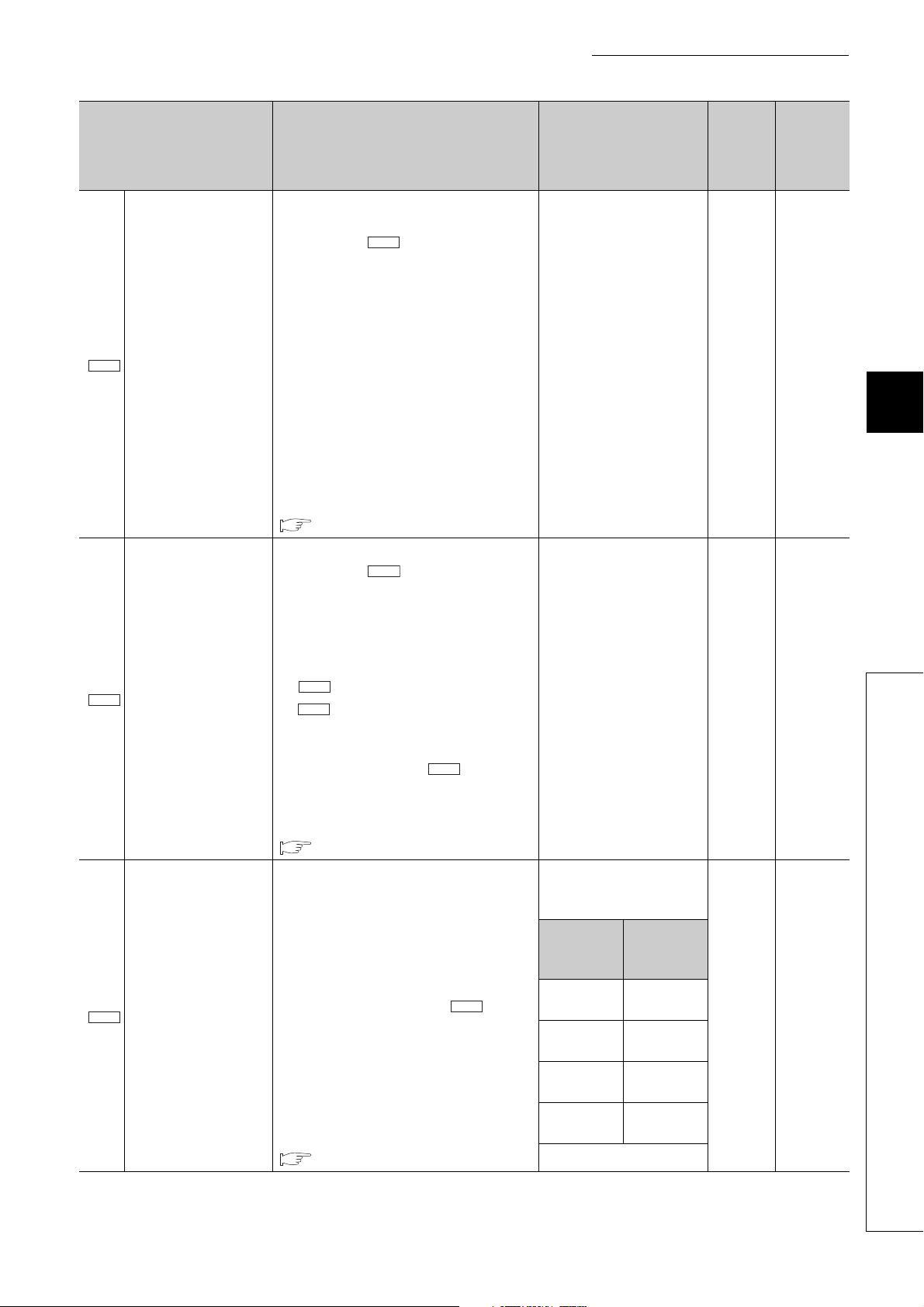
CHAPTER 5 DATA USED FOR POSITIONING
Cd.7
Cd.1
Cd.8
Cd.2
Cd.2
Pr.5
Pr.5
Cd.9
Item Description Setting range
• Use this area to request a current value
change.
• After setting " New current value", set
"1" in this area. If a value other than "1" is
set, the setting is ignored.
• After the current value change was
accepted, "0" is stored automatically.
• A current value change cannot be
Current value change
request
Speed change request
Analog output
adjustment area 2
requested while BUSY signal (X14) is on.
Check that BUSY signal (X14) is off before
requesting a current value change.
• If a current value change is requested while
BUSY signal (X14) is on, the error "Current
value change error" (error code: 110)
occurs.
For details on the current value change
function, refer to the following.
Page 217, Section 11.5
• Use this area to request a speed change.
• After setting " New speed value", set
"1" in this area. If a value other than "1" is
set, the setting is ignored.
• After the speed change was accepted, "0" is
stored automatically.
• If a speed change is requested with
" New speed value" exceeding
" Speed limit value", the error "New
speed value Outside the setting range"
(error code: 40) occurs, and the speed after
the change is limited to " Speed limit
value".
For details on the speed change function,
refer to the following.
Page 218, Section 11.6
• Set pulse amount to adjust gain with
specific accumulated pulse amount.
• This setting is enabled only in the zero/gain
adjustment mode.
• Use this area when one of the selections 5
to 8 is set in "Accumulated pulse setting
the switch setting. (When one of the
selections 1 to 4 is set, use " Analog
output adjustment area 1".)
• If the setting is outside the setting range, the
error "Analog output adjustment area 2
Outside the setting range" (error code: 126)
occurs.
For details on zero/gain adjustment, refer to
the following.
Page 59, Section 4.5
Cd.5
" in
1: Change the current value 0 90
1: Change speed 0 91
Depends on "Accumulated
pulse setting" in the switch
setting.
Accumulated
pulse setting
Selection 5
Selection 6
Selection 7
Selection 8
Setting
range (Unit:
pulse)
-37000 to
37000
-74000 to
74000
-111 0 0 0 t o
111000
-148000 to
148000
Default
value
0
Buffer
memory
address
(decimal)
92
93
5
5.6 Control Data
91
Page 94

Item Description Setting range
Cd.10
Cd.11
Ex.
Cd.12
• Specify "zero adjustment" or "gain
adjustment".
• When zero/gain adjustment is performed
using switches on the front of the QD73A1,
Zero/gain adjustment
specification
Zero/gain adjustment
value specification
Factory default
zero/gain adjustment
value restoration
request
the set value is ignored.
• If a value other than 0, 1, and 2 is set, the
error "Zero/gain adjustment setting error"
(error code: 123) occurs.
For details on zero/gain adjustment, refer to
the following.
Page 59, Section 4.5
• Use this area to set adjustment amount of
the analog output value during zero/gain
adjustment.
• The analog output value changes by the
adjustment amount when Set value change
request signal (Y1C) is turned on and off.
When 1000 is set, the analog output
value can be adjusted by approximately
0.33V.
• When zero/gain adjustment is performed
using switches on the front of the QD73A1,
the set value is ignored.
• If the setting is outside the setting range, the
error "Zero/gain adjustment value error"
(error code: 124) occurs.
For details on zero/gain adjustment, refer to
the following.
Page 59, Section 4.5
• Use this area to restore the zero adjustment
value and gain adjustment value to the
factory default.
• This setting is enabled only in the zero/gain
adjustment mode.
• If a value other than "1" is set, the setting is
ignored.
• After the zero/gain adjustment value was
restored, "0" is stored automatically.
1: Zero adjustment
2: Gain adjustment
-3000 to 3000 0 95
1: Restore the zero/gain
adjustment value
Buffer
Default
value
memory
address
(decimal)
094
096
92
Page 95

CHAPTER 5 DATA USED FOR POSITIONING
Cd.13
Cd.17
Cd.17
Cd.17
Cd.17
Item Description Setting range
The difference between the reference value
(maximum value) and the judgment value
(alert output accumulated pulses (maximum
value)) is set.
The relation between this setting and the
judgment value is as follows.
[If " Accumulated pulse setting value
Alert output
accumulated pulse
setting value (maximum
value)
selection" is set to 0]
Alert output accumulated pulses (maximum
value) = reference value (maximum value) +
Cd.13
Alert output accumulated pulse setting
value (maximum value)
[If " Accumulated pulse setting value
selection" is set to 1]
Alert output accumulated pulses (maximum
value) = reference value (maximum value) +
Cd.13
( Alert output accumulated pulse setting
value (maximum value) - 1000) × reference
value (maximum value) 1000
• If " Accumulated
pulse setting value
selection" is set to 0:
1 to 148000 pulse
• If " Accumulated
pulse setting value
selection" is set to 1:
1000 to 50000
-3
(× 10
: Last three digits
are the value after the
decimal point.)
Default
value
0
Buffer
memory
address
(decimal)
5
400
401
For details on the accumulated pulse error
detection function, refer to the following.
Page 223, Section 11.9
5.6 Control Data
93
Page 96

Item Description Setting range
Cd.14
Cd.17
Cd.14
The difference between the reference value
(maximum value) and the judgment value
(immediate stop accumulated pulses
(maximum value)) is set.
The relation between this setting and the
judgment value is as follows.
[If " Accumulated pulse setting value
selection" is set to 0]
Cd.17
• If " Accumulated
pulse setting value
selection" is set to 0:
1 to 148000 pulse
Cd.17
• If " Accumulated
pulse setting value
selection" is set to 1:
1000 to 50000
-3
(× 10
are the value after the
decimal point.)
Immediate stop
accumulated pulse
setting value (maximum
value)
Immediate stop accumulated pulses
(maximum value) = reference value
(maximum value) + Immediate stop
Cd.14
accumulated pulse setting value (maximum
value)
Cd.17
[If " Accumulated pulse setting value
selection" is set to 1]
Immediate stop accumulated pulses
(maximum value) = reference value
(maximum value) + ( Immediate stop
accumulated pulse setting value (maximum
value) - 1000) × reference value (maximum
value) 1000
: Last three digits
Default
value
0
Buffer
memory
address
(decimal)
402
403
For details on the accumulated pulse error
detection function, refer to the following.
Page 223, Section 11.9
94
Page 97

CHAPTER 5 DATA USED FOR POSITIONING
Cd.15
Cd.17
Cd.17
Cd.17
Cd.17
Item Description Setting range
The difference between the reference value
(minimum value) and the judgment value (alert
output accumulated pulses (minimum value))
is set.
The relation between this setting and the
judgment value is as follows.
[If " Accumulated pulse setting value
Alert output
accumulated pulse
setting value (minimum
value)
selection" is set to 0]
Alert output accumulated pulses (minimum
value) = reference value (minimum value) +
Cd.15
Alert output accumulated pulse setting
value (minimum value)
[If " Accumulated pulse setting value
selection" is set to 1]
Alert output accumulated pulses (minimum
value) = reference value (minimum value) +
Cd.15
( Alert output accumulated pulse setting
value (minimum value) - 1000) × reference
value (minimum value) 1000
• If " Accumulated
pulse setting value
selection" is set to 0:
-148000 to -1 pulse
• If " Accumulated
pulse setting value
selection" is set to 1:
1000 to 50000
-3
(× 10
: Last three digits
are the value after the
decimal point.)
Default
value
0
Buffer
memory
address
(decimal)
5
404
405
For details on the accumulated pulse error
detection function, refer to the following.
Page 223, Section 11.9
5.6 Control Data
95
Page 98

Item Description Setting range
Cd.16
Cd.17
Cd.16
Cd.17
Cd.13
The difference between the reference value
(minimum value) and the judgment value
(immediate stop accumulated pulses
(minimum value)) is set.
The relation between this setting and the
judgment value is as follows.
[If " Accumulated pulse setting value
Immediate stop
accumulated pulse
setting value (minimum
value)
selection" is set to 0]
Immediate stop accumulated pulses
(minimum value) = reference value (minimum
value) + Immediate stop accumulated
pulse setting value (minimum value)
Cd.17
[If " Accumulated pulse setting value
selection" is set to 1]
Immediate stop accumulated pulses
(minimum value) = reference value (minimum
value) + ( Immediate stop accumulated
Cd.16
pulse setting value (minimum value) - 1000) ×
reference value (minimum value) 1000
Cd.17
• If " Accumulated
pulse setting value
selection" is set to 0:
-148000 to -1 pulse
Cd.17
• If " Accumulated
pulse setting value
selection" is set to 1:
1000 to 50000
-3
(× 10
are the value after the
decimal point.)
: Last three digits
Default
value
0
Buffer
memory
address
(decimal)
406
407
Accumulated pulse
setting value selection
For details on the accumulated pulse error
detection function, refer to the following.
Page 223, Section 11.9
• The setting unit for " Alert output
accumulated pulse setting value (maximum
value)" to " Immediate stop
Cd.16
accumulated pulse setting value (minimum
value)" is selected.
• If a value other than 0 and 1 is set, the value
is regarded as 0.
• If this area is set to 1 and the
maximum/minimum reference values are
set to 0, the error "Accumulated pulse error
undetectable" (error code: 131) occurs and
the accumulated pulse error detection
function does not operate.
For details on the accumulated pulse error
detection function, refer to the following.
Page 223, Section 11.9
0: Set with pulse
1: Set with magnification
0: Set
with
pulse
408
96
Page 99

CHAPTER 5 DATA USED FOR POSITIONING
Cd.18
Cd.19
Cd.19
Cd.19
Cd.18
Item Description Setting range
• Use this area to start/stop the accumulated
pulse error detection function.
• While this area is set to 1, the accumulated
pulse error detection function is executed.
However, if the reference value has never
been measured, the error "Accumulated
pulse error undetectable" (error code: 131)
occurs and the function does not operate.
• If a value other than 0 and 1 is set, the value
Accumulated pulse error
detection request
is regarded as 0.
• If " Measurement start request" is set
to 1, the function does not operate even if
this area is set to 1. (This request is ignored
and after " Measurement start
request" is set to 0, the function is
executed.)
0: No request
1: Requested
Default
value
0: No
request
Buffer
memory
address
(decimal)
409
5
Measurement start
request
For details on the accumulated pulse error
detection function, refer to the following.
Page 223, Section 11.9
• Use this area to measure accumulated
pulses used as the reference value to detect
an error.
• While this area is set to 1, the
maximum/minimum accumulated pulse
values are measured.
• If a value other than 0 and 1 is set, the value
is regarded as 0.
Cd.18
• If " Accumulated pulse error detection
request" is set to 1, the value is not
measured even if this area is set to 1. (This
request is ignored and after
" Accumulated pulse error detection
request" is set to 0, the function is
executed.)
For details on the accumulated pulse error
detection function, refer to the following.
Page 223, Section 11.9
0: No request
1: Requested
0: No
request
410
5.6 Control Data
97
Page 100

Item Description Setting range
Cd.20
Md.20
• Use this area to save the measured
reference value in the flash ROM of the
QD73A1.
• When this area setting is changed to 1, the
measured reference value is saved in the
flash ROM.
• When " Reference value
measurement flag" is set to 1, the value is
written to the flash ROM. If
Md.20
Reference value write
request
" Reference value measurement flag"
is set to the value other than 1, the error
"Reference value write error" (error code:
132) occurs and the value is not written.
• The QD73A1 set this area to 0 when the
value saving in the flash ROM is completed.
This process is the same when an error
occurs and the value is not written.
For details on the accumulated pulse error
detection function, refer to the following.
Page 223, Section 11.9
0: No request
1: Requested
Default
value
0: No
request
Buffer
memory
address
(decimal)
411
98
 Loading...