


SAFETY INSTRUCTIONS
(Always read these instructions before using this equipment.)
Before using this product, please read this manual and the relevant manuals introduced in this manual
carefully and pay full attention to safety to handle the product correctly.
The instructions given in this manual are concerned with this product. For safety precautions for
programmable controller systems, refer to the user’s manual of the CPU module used.
In this manual, the safety instructions are ranked as "DANGER" and "CAUTION".
DANGER
!
CAUTION
!
Note that the !CAUTION level may lead to a serious consequence according to the circumstances.
Always follow the instructions of both levels because they are important to personal safety.
Please save this manual to make it accessible when required and always forward it to the end user.
Indicates that incorrect handling may cause hazardous conditions,
resulting in death or severe injury.
Indicates that incorrect handling may cause hazardous conditions,
resulting in medium or slight personal injury or physical damage.
[DESIGN INSTRUCTION]
!
DANGER
• Provide a safety circuit outside the programmable controller so that the entire system will
operate safely even when an external power supply error or programmable controller fault
occurs.
Failure to observe this could lead to accidents for incorrect outputs or malfunctioning.
(1) Configure an emergency stop circuit and interlock circuit such as a positioning control
upper limit/lower limit to prevent mechanical damage outside the programmable controller.
(2) The machine OPR operation is controlled by the OPR direction and OPR speed data.
Deceleration starts when the near-point dog turns ON. Thus, if the OPR direction is
incorrectly set, deceleration will not start and the machine will continue to travel. Configure
an interlock circuit to prevent mechanical damage outside the programmable controller.
(3) When the module detects an error, deceleration stop will take place.
Make sure that the OPR data and positioning data are within the parameter setting values.
!
CAUTION
• Do not bundle or adjacently lay the control wire or communication cable with the main circuit or
power wire.
Separate these by 100mm (3.94in.) or more.
Failure to observe this could lead to malfunctioning caused by noise.
A - 1 A - 1

[MOUNTING INSTRUCTIONS]
!
CAUTION
• Use the programmable controller under the environment specified in the User’s Manual of the
CPU used.
Using the programmable controller outside the general specification range environment could
lead to electric shocks, fires, malfunctioning, product damage or deterioration.
• While pressing the installation lever located at the bottom of module, insert the module fixing tab
into the fixing hole in the base unit until it stops. Then, securely mount the module with the fixing
hole as a supporting point. Improper loading of the module can cause a malfunction, failure or
drop.
For use in vibratory environment, tighten the module with screws.
Tighten the screws within the specified torque range.
Undertightening can cause a drop, short circuit or malfunction.
Overtightening can cause a drop, short circuit or malfunction due to damage to the screws or
module.
• Before installing or removing the module, be sure to shut off all phases of the external power
supply used in the system. Failure to do so may cause damage to the product.
• Do not directly touch the conductive section and electronic parts of the module.
Failure to observe this could lead to module malfunctioning or trouble.
[WIRING INSTRUCTIONS]
!
DANGER
• Always confirm the terminal layout before connecting the wires to the module.
• Make sure that foreign matter, such as cutting chips or wire scraps, do not enter the module.
Failure to observe this could lead to fires, trouble or malfunctioning.
[STARTUP/MAINTENANCE INSTRUCTIONS]
!
DANGER
• Before cleaning or retightening the mounting screws, be sure to shut off all phases of the
external power supply used in the system.
Failure to turn all phases OFF could lead to electric shocks.
A - 2 A - 2

[STARTUP/MAINTENANCE INSTRUCTIONS]
!
CAUTION
• Never disassemble or modify the module.
Failure to observe this could lead to trouble, malfunctioning, injuries or fires.
• Before installing or removing the module, be sure to shut off all phases of the external power
supply used in the system.
Failure to turn all phases OFF could lead to module trouble or malfunctioning.
• Do not install/remove the module to/from the base unit more than 50 times after the first use of
the product. (IEC 61131-2 compliant)
Failure to do so may cause malfunction.
• Before starting test operation, set the parameter speed limit value to the slowest value, and
make sure that operation can be stopped immediately if a hazardous state occurs.
• Always make sure to touch the grounded metal to discharge the electricity charged in the body,
etc., before touching the module.
Failure to do so may cause a failure or malfunctions of the module.
[DISPOSAL INSTRUCTIONS]
!
CAUTION
• When disposing of the product, handle it as industrial waste.
A - 3 A - 3

REVISIONS
* The manual number is given on the bottom left of the back cover.
Print Date * Manual Number Revision
May, 2006 SH (NA)-080551ENG-A First edition
May, 2006 SH (NA)-080551ENG-B
Modifications
Section 11.7, Appendix 3.1
Jun., 2006 SH (NA)-080551ENG-C
Modifications
Section 2.3, Section 4.6.1, Section 10.1, Section 11.2
Jan., 2008 SH (NA)-080551ENG-D
Modifications
GENERIC TERMS AND ABBREVIATIONS, Section 2.3 to 2.6,
Section 6.2.2
May, 2008 SH (NA)-080551ENG-E
Modifications
SAFETY INSTRUCTIONS, Compliance with the EMC and Low
Voltage Directives, Section 2.3, 2.6, 3.1, 5.4.1, 6.2.1, 6.3.1, 6.3.3,
9.2.3
Japanese Manual Version SH-080550-D
This manual confers no industrial property rights or any rights of any other kind, nor does it confer any patent
licenses. Mitsubishi Electric Corporation cannot be held responsible for any problems involving industrial property
rights which may occur as a result of using the contents noted in this manual.
© 2006 MITSUBISHI ELECTRIC CORPORATION
A - 4 A - 4

INTRODUCTION
Thank you for purchasing the Mitsubishi programmable controller MELSEC-Q series.
Always read through this manual, and fully comprehend the functions and performance of the Q series
programmable controller before starting use to ensure correct usage of this product.
CONTENTS
SAFETY INSTRUCTIONS.............................................................................................................................A- 1
REVISIONS ....................................................................................................................................................A- 4
INTRODUCTION............................................................................................................................................A- 5
CONTENTS....................................................................................................................................................A- 5
Using This Manual..........................................................................................................................................A- 9
Compliance with the EMC and Low Voltage Directives................................................................................A- 9
Generic Terms and Abbreviations ................................................................................................................A- 10
Component List .............................................................................................................................................A- 10
SECTION 1 PRODUCT SPECIFICATIONS AND HANDLING
1 PRODUCT OUTLINE 1- 1 to 1- 15
1.1 Positioning control .................................................................................................................................... 1- 1
1.1.1 Features of QD70D ........................................................................................................................... 1- 1
1.1.2 Mechanism of positioning control ..................................................................................................... 1- 3
1.1.3 Outline design of positioning control system.................................................................................... 1- 5
1.1.4 Communicating signals between QD70D and each module........................................................... 1- 9
1.2 Positioning control ................................................................................................................................... 1- 11
1.2.1 Outline of starting ............................................................................................................................. 1- 11
1.2.2 Outline of stopping ........................................................................................................................... 1- 13
2 SYSTEM CONFIGURATION 2- 1 to 2- 9
2.1 General image of system ......................................................................................................................... 2- 1
2.2 Component list ......................................................................................................................................... 2- 2
2.3 Applicable systems .................................................................................................................................. 2- 3
2.4 About Use of the QD70D with the Q12PRH/Q25PRHCPU ................................................................... 2- 6
2.5 About Use of the QD70D on the MELSECNET/H Remote I/O Station.................................................. 2- 7
2.6 How to check the function version and the software version .................................................................2- 8
3 SPECIFICATIONS AND FUNCTIONS 3- 1 to 3- 14
3.1 Performance specifications...................................................................................................................... 3- 1
3.2 List of functions ........................................................................................................................................ 3- 2
3.3 Specifications of input/output signal with Programmable Controller CPU .............................................3- 4
3.3.1 List of input/output signals with programmable controller CPU ....................................................... 3- 4
3.3.2 Details of input signal (QD70D
3.3.3 Details of output signals (Programmable controller CPU
3.4 Specifications of input/output interfaces with external device ................................................................ 3- 7
3.4.1 Electrical specifications of input/output signals ................................................................................ 3- 7
3.4.2 Signal layout for external device connection connector................................................................... 3- 8
3.4.3 List of input/output signal details...................................................................................................... 3- 10
3.4.4 Input/output interface internal circuit................................................................................................ 3- 12
Programmable controller CPU) ................................................. 3- 5
QD70D) ............................................. 3- 6
A - 5 A - 5

4 DATA USED FOR POSITIONING CONTROL(LIST OF BUFFER MEMORY ADDRESSES) 4- 1 to 4- 38
4.1 Type of data ............................................................................................................................................. 4- 1
4.1.1 Parameters and data required for control......................................................................................... 4- 1
4.1.2 Setting items for parameters............................................................................................................. 4- 3
4.1.3 Setting items for OPR data ............................................................................................................... 4- 4
4.1.4 Setting items for JOG data................................................................................................................ 4- 5
4.1.5 Setting items for positioning data...................................................................................................... 4- 6
4.1.6 Type and roles of monitor data ......................................................................................................... 4- 7
4.1.7 Type and roles of control data ..........................................................................................................4- 8
4.2 List of parameters .................................................................................................................................... 4- 9
4.3 List of OPR data ...................................................................................................................................... 4- 19
4.4 List of JOG data ......................................................................................................................................4- 27
4.5 List of positioning data ............................................................................................................................ 4- 28
4.6 List of monitor data.................................................................................................................................. 4- 34
4.6.1 Axis monitor data.............................................................................................................................. 4- 34
4.6.2 Module information monitor data ..................................................................................................... 4- 36
4.7 List of control data ...................................................................................................................................4- 37
4.7.1 Axis control data ...............................................................................................................................4- 37
5 SETUP AND PROCEDURES BEFORE OPERATION 5- 1 to 5- 21
5.1 Handling precautions ............................................................................................................................... 5- 1
5.2 Procedures before operation ................................................................................................................... 5- 3
5.3 Part identification nomenclature ..............................................................................................................5- 4
5.4 Wiring ....................................................................................................................................................... 5- 7
5.4.1 Wiring precautions............................................................................................................................. 5- 7
5.5 Confirming the wiring .............................................................................................................................. 5- 12
5.5.1 Confirmation items at completion of wiring ..................................................................................... 5- 12
5.6 Switch setting for intelligent function module ......................................................................................... 5- 14
5.7 Simple reciprocating operation ............................................................................................................... 5- 19
6 UTILITY PACKAGE (GX Configurator-PT) 6- 1 to 6- 19
6.1 Utility package functions .......................................................................................................................... 6- 1
6.2 Installing and Uninstalling the Utility Package ........................................................................................ 6- 2
6.2.1 Handling precautions ........................................................................................................................ 6- 2
6.2.2 Operating environment...................................................................................................................... 6- 4
6.3 Utility Package Operation ........................................................................................................................ 6- 6
6.3.1 Common utility package operations ................................................................................................. 6- 6
6.3.2 Operation overview ........................................................................................................................... 6- 8
6.3.3 Starting the Intelligent function module utility ..................................................................................6- 10
6.4 Initial setting............................................................................................................................................. 6- 12
6.5 Auto refresh setting ................................................................................................................................. 6- 14
6.6 Monitoring/test......................................................................................................................................... 6- 16
6.6.1 Monitoring/Test screen..................................................................................................................... 6- 16
7 SEQUENCE PROGRAM USED FOR POSITIONING CONTROL 7- 1 to 7- 26
7.1 Precautions for creating program ............................................................................................................ 7- 1
7.2 List of devices used.................................................................................................................................. 7- 3
A - 6 A - 6

7.3 Creating a program ..................................................................................................................................7- 7
7.3.1 General configuration of program ..................................................................................................... 7- 7
7.3.2 Positioning control operation program.............................................................................................. 7- 8
7.4 Positioning control program examples ................................................................................................... 7- 10
7.5 Program details ....................................................................................................................................... 7- 16
7.5.1 Initialization program ........................................................................................................................7- 16
7.5.2 Start method setting program ..........................................................................................................7- 17
7.5.3 Start program.................................................................................................................................... 7- 17
7.5.4 Sub program .....................................................................................................................................7- 23
SECTION 2 CONTROL DETAILS AND SETTING
8 OPR CONTROL 8- 1 to 8- 21
8.1 Outline of OPR control ............................................................................................................................. 8- 1
8.1.1 Two types of OPR control ................................................................................................................. 8- 1
8.2 Machine OPR control ............................................................................................................................... 8- 2
8.2.1 Outline of the machine OPR operation............................................................................................. 8- 2
8.2.2 Machine OPR method....................................................................................................................... 8- 3
8.2.3 OPR method (1): Near-point dog method ........................................................................................ 8- 5
8.2.4 OPR method (2): Stopper 1 .............................................................................................................. 8- 8
8.2.5 OPR method (3): Stopper 2 ............................................................................................................. 8- 10
8.2.6 OPR method (4): Stopper 3 ............................................................................................................. 8- 12
8.2.7 OPR method (5): Count 1 ................................................................................................................8- 14
8.2.8 OPR method (6): Count 2 ................................................................................................................8- 16
8.3 Fast OPR control..................................................................................................................................... 8- 18
8.3.1 Outline of the fast OPR control operation........................................................................................ 8- 18
8.4 OPR retry function................................................................................................................................... 8- 19
9 POSITIONING CONTROL 9- 1 to 9- 18
9.1 Outline of positioning controls.................................................................................................................. 9- 1
9.1.1 Data required for positioning control................................................................................................. 9- 1
9.1.2 Operation patterns of positioning controls........................................................................................ 9- 2
9.1.3 Designating the positioning address................................................................................................. 9- 8
9.1.4 Confirming the current value............................................................................................................. 9- 9
9.2 Setting the positioning data .................................................................................................................... 9- 10
9.2.1 Relation between each control and positioning data ...................................................................... 9- 10
9.2.2 1-axis linear control .......................................................................................................................... 9- 11
9.2.3 Speed-position switching control ..................................................................................................... 9- 13
9.2.4 Current value changing .................................................................................................................... 9- 16
9.3 Multiple axes simultaneous start control ................................................................................................9- 17
10 JOG OPERATION 10- 1 to 10- 6
10.1 Outline of JOG operation ..................................................................................................................... 10- 1
10.2 JOG operation execution procedure ...................................................................................................10- 3
10.3 JOG operation example .......................................................................................................................10- 4
11 SUB FUNCTIONS 11- 1 to 11- 17
11.1 Outline of sub functions ....................................................................................................................... 11- 1
A - 7 A - 7

11.2 Speed limit function.............................................................................................................................. 11- 1
11.3 Speed change function ........................................................................................................................ 11- 2
11.4 Software stroke limit function ............................................................................................................... 11- 5
11.5 Target position change function .......................................................................................................... 11- 9
11.6 Acceleration/deceleration processing function................................................................................... 11- 11
11.7 Restart function ...................................................................................................................................11- 15
12 COMMON FUNCTIONS 12- 1 to 12- 3
12.1 Outline of common functions ............................................................................................................... 12- 1
12.2 External I/O signal switching function.................................................................................................. 12- 1
12.3 External I/O signal monitor function .................................................................................................... 12- 2
13 TROUBLESHOOTING 13- 1 to 13- 16
13.1 Error and warning details ..................................................................................................................... 13- 1
13.2 List of errors ......................................................................................................................................... 13- 3
13.3 List of warnings ................................................................................................................................... 13- 13
13.4 Error check by LED indication ............................................................................................................ 13- 15
13.5 Confirming the error definitions using system monitor of GX Developer .......................................... 13- 16
APPENDIX App- 1 to App- 16
Appendix 1 External dimension drawing ...................................................................................................App- 1
Appendix 2 Operation timing and processing time in each control ..........................................................App- 2
Appendix 3 Connection examples with servo amplifiers manufactured by MITSUBISHI Electric Corporation
.................................................................................................................................................App- 6
Appendix 3.1 Connection example of QD70D and MR-J3Appendix 3.2 Connection example of QD70D and MR-J2/J2SAppendix 3.3 Connection example of QD70D and MR-HAppendix 3.4 Connection example of QD70D and MR-C-
Appendix 4 Comparisons with conventional positioning modules............................................................App-10
Appendix 4.1 Comparisons with type QD70P positioning module .......................................................App-10
Appendix 4.2 Comparisons with type QD75 positioning module..........................................................App-11
Appendix 5 List of buffer memory addresses ............................................................................................App-14
INDEX Index- 1 to Index- 5
A.............................................................App- 6
A .....................................................App- 7
A..............................................................App- 8
A..............................................................App- 9
A - 8 A - 8

Using This Manual
Compliance with the EMC and Low Voltage Directives
The symbols used in this manual are shown below.
Pr.
OPR.
JOG.
Da.
Md.
Cd.
(A serial No. is inserted in the
Numeric values used in this manual
• The buffer memory addresses, error codes and warning codes are represented
in decimal.
• The X/Y devices are represented in hexadecimal.
• The setting data and monitor data are represented in either decimal or
hexadecimal. The data ended by "H" are represented in hexadecimal.
...... Symbol indicating positioning parameter item.
....... Symbol indicating OPR data item.
....... Symbol indicating JOG data item.
...... Symbol indicating positioning data item.
...... Symbol indicating monitor data item.
....... Symbol indicating control data item.
(Example) 10......... 10 Decimal
10H ......16 Hexadecimal
(1) For programmable controller system
To configure a system meeting the requirements of the EMC and Low Voltage
Directives when incorporating the Mitsubishi programmable controller (EMC and
Low Voltage Directives compliant) into other machinery or equipment, refer to
Chapter 9 "EMC AND LOW VOLTAGE DIRECTIVES" of the QCPU User's
Manual (Hardware Design, Maintenance and Inspection).
The CE mark, indicating compliance with the EMC and Low Voltage Directives, is
printed on the rating plate of the programmable controller.
(2) For the product
To make this product conform to the EMC and Low Voltage Directives, please
refer to Section 5.4.1 "Wiring precautions".
mark.)
A - 9 A - 9

Generic Terms and Abbreviations
Unless specially noted, the following generic terms and abbreviations are used in this
manual.
Generic term/abbreviation Details of generic term/abbreviation
Programmable controller
CPU
QD70D Generic term for type QD70D positioning module QD70D4/QD70D8.
QD70P Generic term for type QD70P positioning module QD70P4/QD70P8.
QD75
Peripheral device
GX Configurator-PT
GX Developer
DOS/V personal computer IBM PC/AT® and compatible DOS/V compliant personal computer.
Personal computer Generic term for DOS/V personal computer.
Workpiece Generic term for moving body such as workpiece and tool, and for various control targets.
Axis 1, axis 2, axis 3,
axis 4, axis 5, axis 6,
axis 7, axis 8
1-axis, 2-axes, 3-axes,
4-axes, 5-axes, 6-axes,
7-axes, 8-axes
Windows Vista®
Windows® XP
Generic term for programmable controller CPU on which QD70D can be mounted.
The module type is described to indicate a specific module.
The module type is described to indicate a specific module.
Generic term for positioning module QD75P1, QD75P2, QD75P4, QD75D1, QD75D2, and
QD75D4.
The module type is described to indicate a specific module.
Generic term for DOS/V personal computer where following "GX Configurator-PT" and ""GX
Developer" have been installed.
Abbreviation for GX Configurator-PT (SW1D5C-QPTU-E) utility package for QD70D
positioning module.
Generic product name for the SWnD5C-GPPW-E, SWnD5C-GPPW-EA, SWnD5C-GPPW-EV
and SWnD5C-GPPW-EVA. ("n" is 4 or greater.)
"-A" and "-V" denote volume license product and upgraded product respectively.
Indicates each axis connected to QD70D.
Indicates the number of axes. (Example: 2-axes = Indicates two axes such as axis 1 and axis
2, axis 2 and axis 3, and axis 3 and axis 1.)
Generic term for the following:
Microsoft
Microsoft
Microsoft
Microsoft® Windows Vista® Ultimate Operating System,
Microsoft
Generic term for the following:
Microsoft
Microsoft
®
Windows Vista® Home Basic Operating System,
®
Windows Vista® Home Premium Operating System,
®
Windows Vista® Business Operating System,
®
Windows Vista® Enterprise Operating System
®
Windows® XP Professional Operating System,
®
Windows® XP Home Edition Operating System
Component List
The component list of this product is given below.
Type Component Quantity
QD70D4 Type QD70D4 Positioning Module (4-axes differential output type) 1
QD70D8 Type QD70D8 Positioning Module (8-axes differential output type) 1
SW1D5C-QPTU-E GX Configurator-PT Version 1 (1-license product) (CD-ROM) 1
SW1D5C-QPTU-EA GX Configurator-PT Version 1 (Multiple-license product) (CD-ROM) 1
A - 10 A - 10

SECTION 1 PRODUCT SPECIFICATIONS
AND HANDLING
SECTION 1
Section 1 is configured for the following purposes (1) to (5).
(1) To understand the outline of positioning control, and the QD70D specifications
and functions
(2) To carry out actual work such as installation and wiring
(3) To set parameters and data required for positioning control
(4) To create a sequence program required for positioning control
Read "Section 2" for details on each control.
CHAPTER 1 PRODUCT OUTLINE ................................................................................. 1- 1 to 1- 15
CHAPTER 2 SYSTEM CONFIGURATION ..................................................................... 2- 1 to 2- 9
CHAPTER 3 SPECIFICATIONS AND FUNCTIONS ...................................................... 3- 1 to 3- 14
CHAPTER 4 DATA USED FOR POSITIONING CONTROL .......................................... 4- 1 to 4- 38
CHAPTER 5 SETUP AND PROCEDURES BEFORE OPERATION............................. 5- 1 to 5- 21
CHAPTER 6 UTILITY PACKAGE.................................................................................... 6- 1 to 6- 19
CHAPTER 7 SEQUENCE PROGRAM USED FOR POSITIONING CONTROL .......... 7- 1 to 7- 26

MEMO
SECTION 1

1 PRODUCT OUTLINE
MELSEC-Q
CHAPTER 1 PRODUCT OUTLINE
This User's Manual provides the specifications, handling, programming methods and
other information of the QD70D positioning module used with the MELSEC-Q series
CPU module.
When diverting any of the program examples introduced in this manual to the actual
system, fully verify that there are no problems in the controllability of the target system.
1.1 Positioning control
1.1.1 Features of QD70D
The following are the features of the QD70D.
(1) Wide assortment of 4-axes and 8-axes modules
The QD70D is a positioning module used in a multi-axes system that does not
need complex control.
It is not compatible with the MELSEC-A series AD70 positioning module in I/O
signals, functions, etc.
(2) About positioning control functions
(a) The QD70D has a number of functions required for a positioning control
system, such as positioning control to any position and equal-speed control.
1) You can set up to 10 pieces of positioning data, which include
positioning address, control method, operation pattern and like, per axis.
These positioning data are used to exercise positioning control axis-byaxis.
2) Axis-by-axis positioning control allows linear control (up to 8 axes can be
controlled simultaneously).
This control can perform positioning termination with one piece of
positioning data or exercise continuous positioning control by continuous
execution of multiple pieces of positioning data.
(b) As the control method, any of position control, speed-position switching
control and current value changing may be specified in each positioning
data.
(c) The target position change function or the speed change function allows the
position or speed change during positioning control.
(d) The OPR (Original Point Return: Zero return) control has been enhanced.
1) The following six different OPR methods are available for "machine
OPRcontrol": near-point dog method (one method), stopper (three
methods) and count (two methods).
2) The OPR retry function has been provided to realize the return from
any given point to a mechanical origin.
(e) Two kinds of the acceleration/deceleration methods have been offered: The
trapezoidal and S-curve acceleration/deceleration
gradually and smoothly, this module is suitable for motor control.
* When "Continuous positioning control" or "Continuous path control" is
selected for the operation pattern, S-curve acceleration/deceleration is not
available.
(f) You can change the I/O signal logic according to the specifications of the
external device.
This allows the input signals to be used with either of "normally open" and
"normally closed" contacts, and the output signals to be used according to
the specifications of the drive unit.
*. As the speed changes
1
1 - 1 1 - 1

1 PRODUCT OUTLINE
1
MELSEC-Q
(3) Fast start processing
Processing at a position control start has been speeded up to shorten the start
processing time of one axis to 0.1ms.
At a simultaneous start of multiple axes (the positioning start signals are turned
ON at the same time within one scan), there are no starting delays between the
axes.
(4) High-speed pulse output and longer connection distance to a drive
unit
By using differential driver output, the speed of pulse command has been
improved (Max. 4 Mpps) and longer connection distance to a driver unit (Max.
10m) has been enabled.
(5) Ease of maintenance
In the QD70D, error definitions have been subdivided to improve maintenance
performance.
(6) Ease of utility package settings
The optionally available utility package (GX Configurator-PT) allows initial setting
and auto refresh setting to be made on the screen, reducing sequence programs
and facilitating the confirmation of the setting status and operating status.
1 - 2 1 - 2
1 PRODUCT OUTLINE
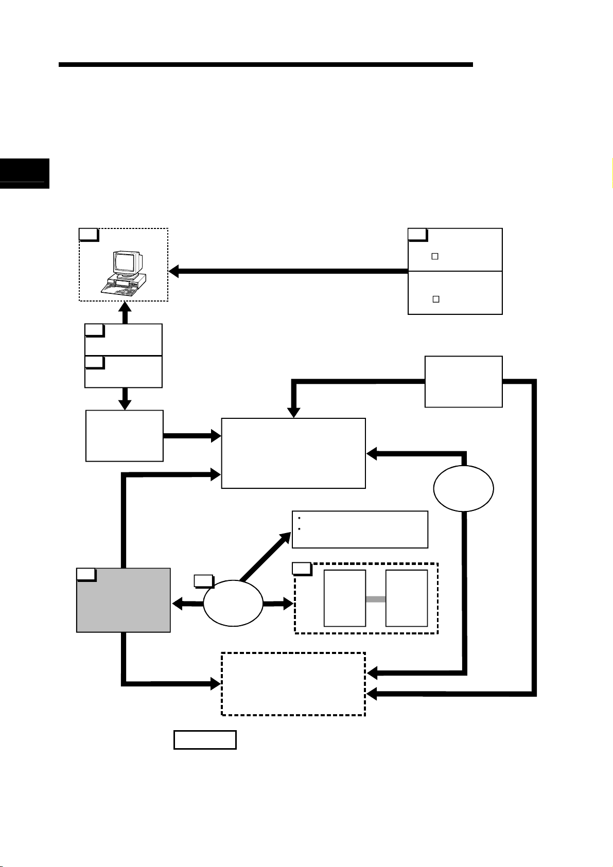
1.1.2 Mechanism of positioning control
Positioning control using the QD70D is exercised using "pulse signals". (The QD70D is
a module that outputs pulses.)
In a positioning control system using the QD70D, a variety of software and external
devices are used to play their roles as shown below.
The QD70D imports various signals, parameters and data, and exercises control with
the programmable controller CPU to realize complex positioning control.
Stores the created program.
MELSEC-Q
Peripheral device
GX Developer/
GX Configurator-PT
Using GX Developer, create
control sequence and conditions
as sequence program.
Adding in GX Configurator-PT
enables initial setting of
parameters and data.
The QD70D outputs the positioning start signal and
axis stop signal following the stired program.
QD70D errors, etc., are detected.
Programmable
controller CPU
Input near-point dog signal and speed
-position switching signal / retry switch
signal to QD70D.
QD70D
positioning
module
Stores the parameter and data
Outputs to the drive unit according to the
instructins from the programmable
Mechanical
system inputs
(Switches)
controller CPU.
Drive
unit
Receives pulses commands from QD70D,
and drives the motor.
Motor
Carries out the actual work according to
commands from the drive unit
Workpiece
1 - 3 1 - 3
1 PRODUCT OUTLINE
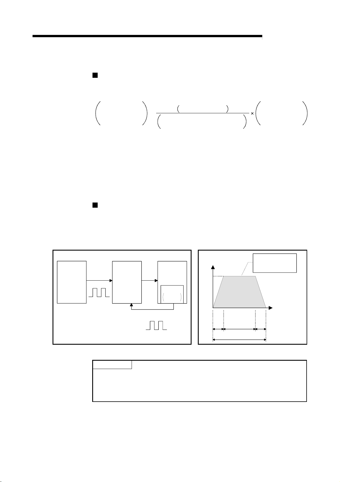
The principle of "position control" and "speed control" operation is shown below.
Position control
The total No. of pulses required to move the designated distance is obtained in the
following manner.
Total No. of pulses
required to move
designated distance
When this total No. of pulses is issued from the QD70D to the drive unit, control to
move the designated distance can be executed.
The machine side movement amount when one pulse is issued to the drive unit is
called the "movement amount per pulse". This value is the min. value for the workpiece
to move, and is also the electrical positioning control precision.
Speed control
Though the above "total No. of pulses" is an element needed to control the
movement amount, speed must be controlled to perform equal-speed operation.
This "speed" is controlled by the "pulse frequency" output from the QD70D to the
drive unit.
Positioning
module
MELSEC-Q
=
Designated distance
Movement amount of machine (load)
side when motor rotates once
* The No. of pulses required for the motor to rotate once is the "encoder resolution"
described in the motor catalog specification list.
No. of pulses
required for motor to
rotate once
Servo
amplifiter
Servo
motor
Pulse frequency
[pps]
A
This area is hte total
No. of commanded
pulses.
Detector
Pulse
encoder
Speed=Pulses frequency
Movement amount=No. of puleses
Feedback pulses=
Pulses generated by detector
Feedback pulses
ta td
0.4 0.41.2
Movement amount t = 2
(s)
Fig. 1.1 Relationship between position control and speed control
POINT
• The "movement amount per pulse" is the value determined on the machine side.
(Refer to Section 1.1.3.)
• The QD70D uses the "total No. of pulses" to control the position, and uses the
"pulse frequency" to control the speed.
1 - 4 1 - 4
1 PRODUCT OUTLINE
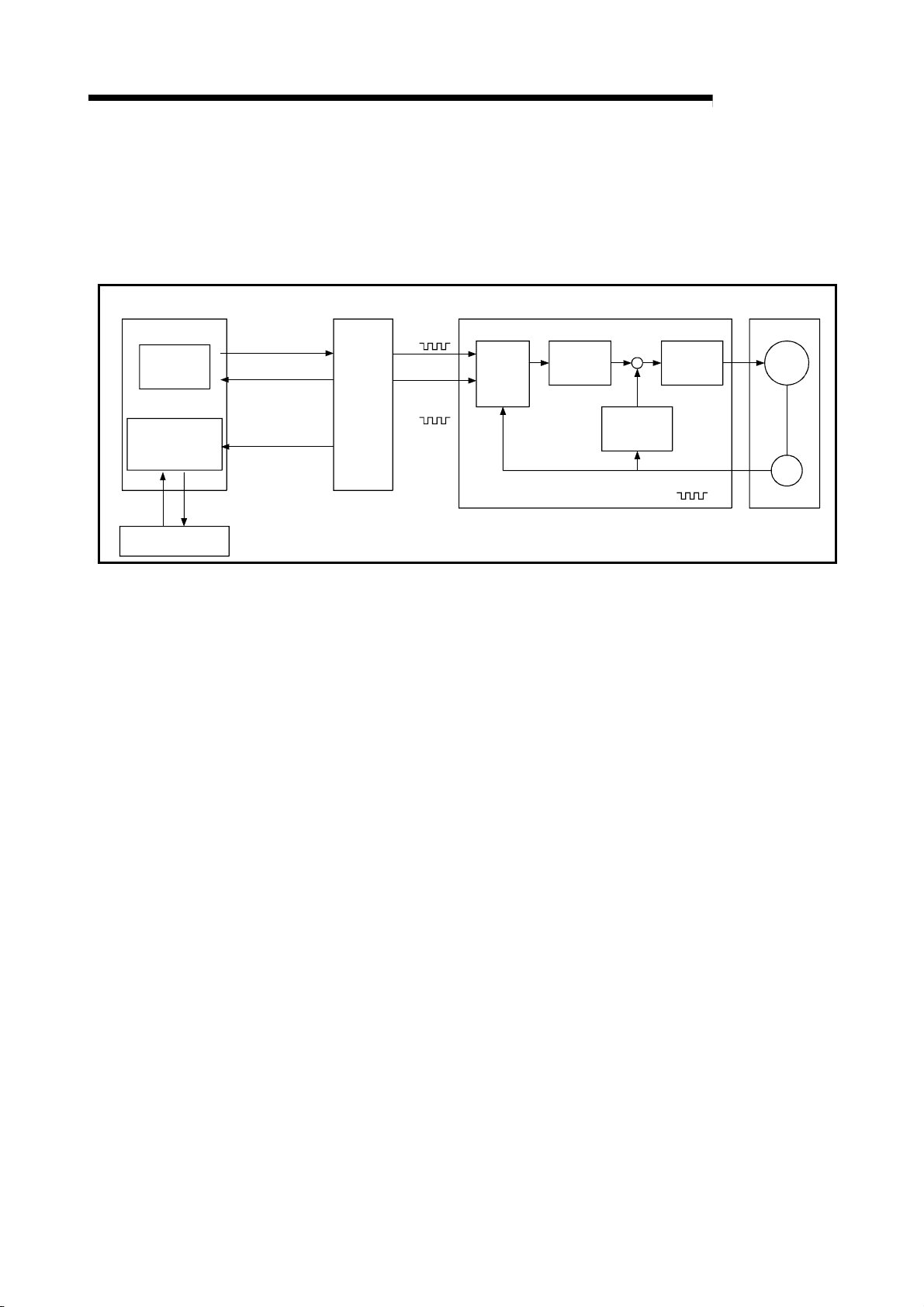
1.1.3 Outline design of positioning control system
The outline of the positioning control system operation and design, using the QD70D,
is shown below.
(1) Positioning control system using QD70D
Programmable controller
CPU
Program
Intelligent
function module
parameter
Initial setting /Auto rofresh setting/Monitor
Read, write, etc.
Monitor date read
QD70D
Buffer
memories
/XY
device
Positioning module
Forward run
pulse train
Reverse run
pulse train
Deviation
counter
MELSEC-Q
Drive unit
D/A
converter
Speed
command
Interface
Feedback pulse
Servo
amplifiter
Servomotor
M
PLG
GX Configurator-PT
Fig. 1.2 Outline of the operation of positioning control system using QD70D
(a) Positioning operation by the QD70D
1) The QD70D output is a pulse train.
The pulse train output by the QD70D is counted by and stored in the
deviation counter in the drive unit.
The D/A converter outputs an analog DC current proportionate to the
count maintained by the deviation counter (called "pulse droop"). The
analog DC current serves as the servomotor speed control signal.
2) The servomotor rotation is controlled by the speed control signal from
the drive unit.
As the servomotor rotates, the pulse encoder (PLG) attached to the
servomotor generates feedback pulses, the frequency of which is
proportionate to the rotation speed.
The feedback pulses are fed back to the drive unit and decrements the
pulse droop, the pulse count maintained by the deviation counter.
The motor keeps on rotating as the pulse droop is maintained at a
certain level.
3) When the QD70D terminates the output of a pulse train, the servomotor
decelerates as the pulse droop decreases and stops when the count
drops to zero.
Thus, the servomotor rotation speed is proportionate to the pulse
frequency, while the overall motor rotation angle is proportionate to the
total number of pulses output by the QD70D.
Therefore, when a movement amount per pulse is given, the overall
movement amount can be determined by the number of pulses in the
pulse train.
The pulse frequency, on the other hand, determines the servomotor
rotation speed (feed speed).
1 - 5 1 - 5

1 PRODUCT OUTLINE
MELSEC-Q
(b) Pulse train output from the QD70D
1) As shown in Fig. 1.3, the pulse frequency increases as the servomotor
accelerates. The pulses are sparse when the servomotor starts and
more frequent when the servomotor speed comes close to the target
speed.
2) The pulse frequency stabilizes when the motor speed equals the target
speed.
3) The QD70D decreases the pulse frequency (sparser pulses) to
decelerate the servomotor before it finally stops the output.
There will be a little difference in timing between the decrease in the
pulse frequency and the actual deceleration and stopping of the
servomotor.
This difference, called "the stop settling time", is required for gaining a
stopping accuracy.
Servomotor
speed
amount
Pulse
distribution
Deceleration
Rough
Speed V Pulse droop
Acceleration
Pulse train Rough Dense
Time t
Stop
setting time
Fig. 1.3 QD70D output pulses
1 - 6 1 - 6
r
ε
1 PRODUCT OUTLINE
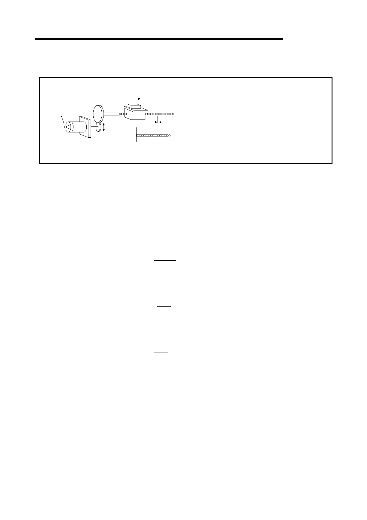
(2) Movement amount and speed in a system using worm gears
Pulse encoder
(PLG)
Servomotor
MELSEC-Q
A : Movement amount per pulse (mm/pulse)
Vs : Command pulse frequency (pulse/s)
V
Table
P0
Workpiece
Worm pea
L
P
n : Pulse encoder resolution (pulse/rev)
L : Worm gear lead (mm/rev)
R : Deceleration ratio
V : Movable section speed (mm/s)
N : Motor speed (r/min)
K : Position loop gain (1/s)
: Deviation counter droop pulse amount
P0 : OP (pulse)
P : Address (pulse)
Fig. 1.4 System using worm gears
In the system shown in Fig. 1.4, the movement amount per pulse, command
pulse frequency, and the deviation counter droop pulser amount are determined
as follows:
1) Movement amount per pulse
The movement amount per pulse is determined by the worm gear lead,
deceleration ratio, and the pulse encoder resolution.
The movement amount, therefore, is given as follows: (Number of
pulses output) × (Movement amount per pulse).
A =
L
R × n
[mm/pulse]
2) Command pulse frequency
The command pulse frequency is determined by the speed of the
moving part and movement amount per pulse.
Vs =
V
A
[pulse/s]
3) Deviation counter droop pulser amount.
The deviation counter droop pulser amount is determined by the
command pulse frequency and position loop gain.
Vs
K
[pulse]
ε =
1 - 7 1 - 7

1 PRODUCT OUTLINE
MEMO
MELSEC-Q
1 - 8 1 - 8
1 PRODUCT OUTLINE
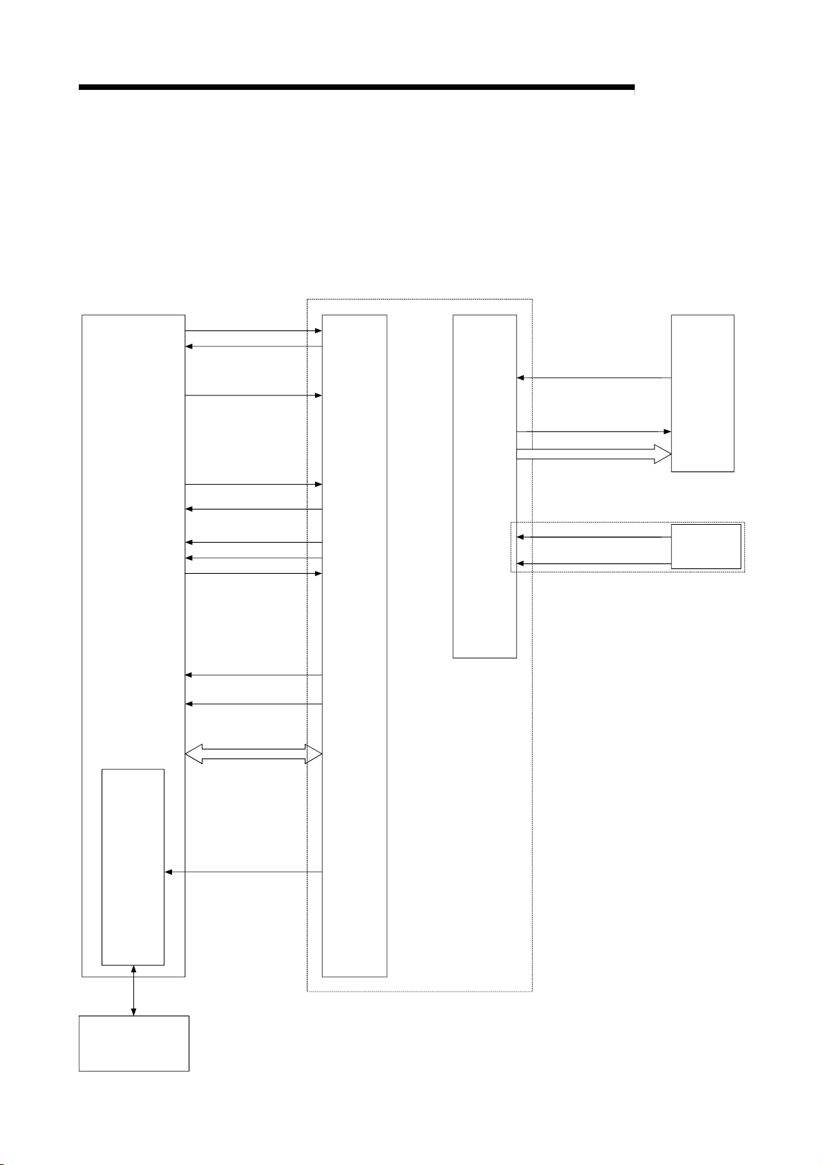
1.1.4 Communicating signals between QD70D and each module
The outline of the signal communication between the QD70D (positioning module) and
programmable controller CPU, peripheral device (GX Configurator-PT) and drive unit,
etc., is shown below.
(A peripheral device communicates with the QD70D via the programmable controller
CPU to which it is connected)
Programmable
controller CPU
Yn0
Xn0
Y(n+1)8 to Y(n+1)F
Refer to Chapter 3 for details of the I/O signals.
Programmable
controller
READY signal
Module READY signal
JOG start signal
QD70D
Zero signal
Deviation counter clear
Pulse train
MELSEC-Q
Drive
unit
Yn8 to YnF
X(n+1)8 to X(n+1)F
Xn8 to XnF
X(n+1)0 to X(n+1)7
Y(n+1)0 to Y(n+1)7
Xn1
Xn2
Peripheral
device
interface
Positioning start
Positioning complete
signal
BUSY signal
Start complete signal
Axis stop signal
Axis error occurrence
Axis warning occurrence
signal
signal
Date write/read
Monitor data
Interface
with
Programmable
controller
CPU
External
interface
Near-point dog singal
Speed-position switching
signal / Retry switch signal
Mechanical
system inputs
(Switches)
Initial setting/Auto refresh/
Operation monitor
Peripheral device
(GX Configurator-PT)
1 - 9 1 - 9
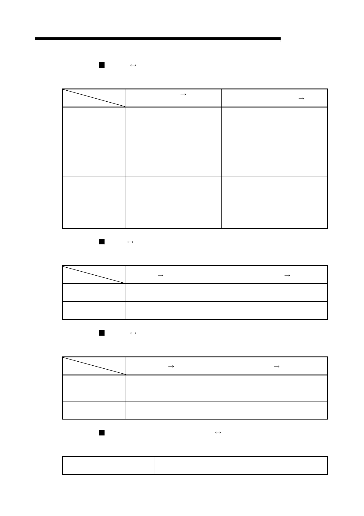
1 PRODUCT OUTLINE
QD70D Programmable controller CPU
The QD70D and programmable controller CPU communicate the following data via
Communication
Control signal
Data (read/write)
the base unit.
Direction
QCPU Peripheral device (GX Configurator-PT)
The QCPU and peripheral device make the following communications. (Refer to
Communication
Data –
Operation monitor
Chapter 6 for details.)
Direction
QD70D Drive unit
The QD70D and drive unit communicate the following data via the external device
Communication
Control signal
Pulse train
connection connector.
Direction
Mechanical system inputs (switches) QD70D
The input signals from the mechanical system inputs (switches) are entered into the
Mechanical system inputs (switches)
QD70D via the external device connection connector.
QD70D
Programmable controller CPU
Signal indication QD70D state.
• Module READY (Xn0)
• Axis error occurrence (Xn1)
• Axis warning occurrence (Xn2)
• BUSY (Xn8 to XnF)
• Start complete (X(n+1)0 to Xn(n+1)7)
• Positioning complete (X(n+1)8 to
X(n+1)F)
• Parameter
• OPR data
• JOG data
• Positioning data
• Control data
• Monitor data
QCPU
• Monitor data (QD70D buffer
memory/XY devices)
Signals related to commands
• Deviation counter clear signal
(CLEAR)
• Pulse train output (PULSE F(+/-)/
PULSE R(+/-))
Peripheral device Peripheral device QCPU
QD70D
Drive unit Drive unit QD70D
• Near-point dog signal (DOG)
• Speed-position switching signal (CHG)/Retry switch signal(RTRY)
MELSEC-Q
Programmable controller CPU
Signal related to commands.
• Programmable controller READY (Yn0)
• Positioning start (Yn8 to YnF)
• Axis stop (Y(n+1)0 to Y(n+1)7)
• JOG start (Y(n+1)8 to Y(n+1)F)
• Parameter
• OPR data
• JOG data
• Positioning data
• Control data
• Initial setting
• Auto refresh setting
–
Signal indicating OP
• Zero signal (PG0)
–
QD70D
1 - 10 1 - 10
1 PRODUCT OUTLINE
1.2 Positioning control
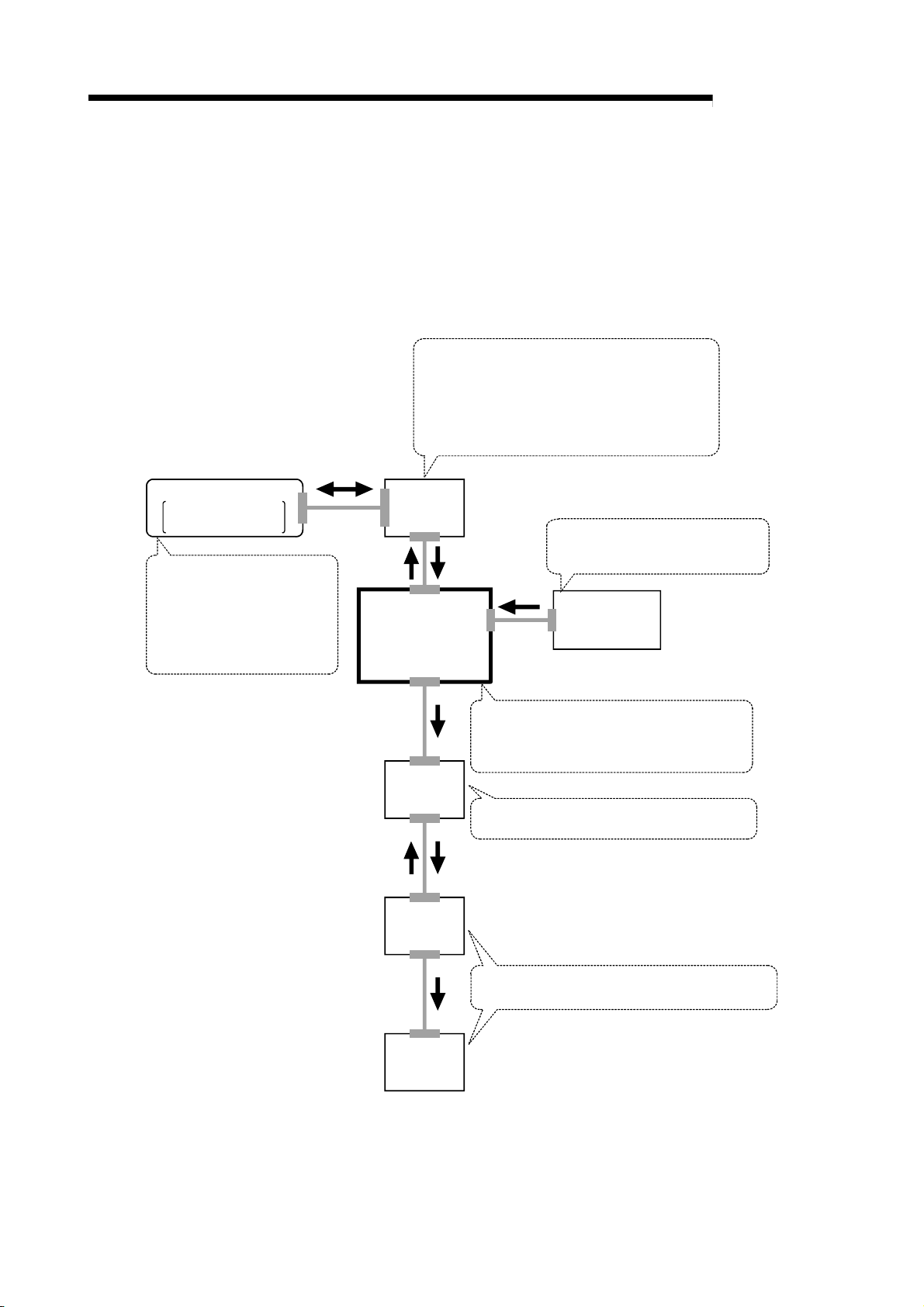
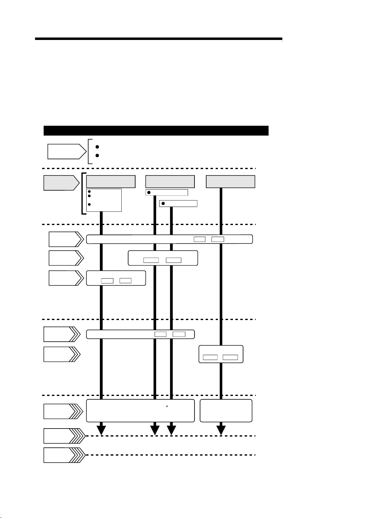
1.2.1 Outline of starting
The outline for starting each control is shown with the following flowchart.
* It is assumed that each module is installed, and the required system configuration,
etc., has been prepared.
Flow of starting
MELSEC-Q
Preparation
Control
functions
Parameter
OPR data
Positioning
data
Installation and connection of module
Setting of hardware
Positioning control
Position control
Speed-position
switching control
Current value
changing
Set the positioning data.
( Da. 1 to Da. 7 )
OPR control
Machine OPR control
Fast OPR control
Set the parameters.
Set the OPR data.
OPR. 1 to
OPR. 9
( Pr. 1 to Pr. 10 )
JOG operation
Control data
JOG data
Start signal
Control start
Control end
Set the start method.( Da. 1 to Da. 7 )
Turn ON the QD70D start signal from
the programmable controller CPU
Operation
Set the JOG data
( JOG. 1 to JOG. 4 )
Turn the QD70D JOG
start signal ON from
the programmable
controller CPU
* : Positioning control can make a
multiple axes simultaneous start.
(Refer to "Section 9.3" for details.)
Stop
1 - 11 1 - 11

1 PRODUCT OUTLINE
MEMO
MELSEC-Q
1 - 12 1 - 12
1 PRODUCT OUTLINE
MELSEC-Q
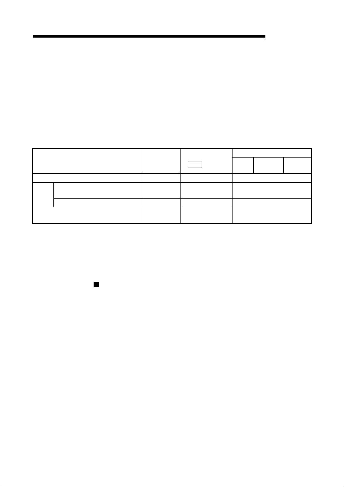
1.2.2 Outline of stopping
The possible causes of a control stop are as follows.
(1) Control ended normally
(2) An error occurred in the programmable controller CPU
(3) An error occurred in the QD70D
(4) The axis stop signal from the programmable controller CPU turned ON
Stop processings performed in the above cases are outlined in the following table.
Stop factor Stopped axis
Programmable controller CPU error All axes Error Deceleration stop
QD70D
error
"Axis stop signal" from programmable controller
CPU turned ON
*1: By making parameter setting, you can set the software stroke limit valid/invalid. When the stroke limit is set invalid, a
*2: If an illegal positioning data setting value caused an error during position control (operation pattern: continuous path
*3: For position control, you can make parameter setting to select the stopping method (position match stop or
Software stroke limit upper/lower limit
1
error *
Other error Axis by axis Error
deceleration stop is not made. (Refer to Section 4.2.)
control), an immediate stop is made at the positioning data preceding that illegal setting value. (Refer to Section 9.1.2.)
deceleration stop). (Refer to Section 4.2.)
(Except the case (1) where control stopped normally)
Axis operation status
Md. 4
(
) after stop
Axis by axis Error Deceleration stop
Axis by axis Stopped
control
Stop processing
OPR
Positioning
control
Deceleration stop *
Deceleration stop *
operation
Stop after multiple axes simultaneous start under positioning control
The axes started will not stop simultaneously. The stop command (axis stop signal
ON) must be given to each axis.
JOG
2
3
1 - 13 1 - 13
1 PRODUCT OUTLINE
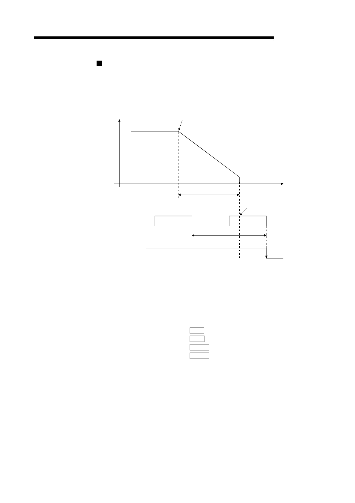
Pulse output operation at stop
When the axis stops due to stop cause occurrence, if there is the pulse being output
when the set deceleration stop time has elapsed from the start of deceleration stop,
the output as much as 1 pulse will be done.
Bias speed at start
The following shows the pulse output operation at deceleration stop.
MELSEC-Q
V
Stop cause occurrence
(Start of deceleration stop)
Set deceleration stop time
*4
*5
Pulse that is being output when set
deceleration stop time has elapsed
will be output.
t
*7
Pulse output
1 pulse
ON
BUSY signal
*6
OFF
*4: "Stop cause" indicates any of the following.
• Error occurred in the programmable controller CPU or QD70D.
• JOG start signal (Y(n+1)8 to Y(n+1)F) has turned OFF during JOG operation.
• Axis stop signal (Y(n+1)0 to Y(n+1)7) has turned ON.
• Speed change to speed 0 (pulse/s) (when bias speed at start is 0 (pulse/s))
• Machine OPR control of count 2
*5: "Set deceleration stop time" is any of the following.
• During positioning control :
• At speed change to speed 0 (pulse/s) :
• During machine OPR control of count 2 :
• During JOG operation :
*6: When the axis is decelerated to a stop by a speed change to speed 0 (pulse/s), the BUSY signal does
not turn OFF.
*7: The same operation is performed when an immediate stop cause occurs during machine OPR control
(except the case of count 2).
*8: Pulse output can be set to stop at the point of time when "Preset deceleration stop time" is elapsed.
For details, refer to section 4.1 Type of data, "Pr.12 Pulse output method (stop signal enabled)".
Da. 4
Cd. 9
OPR. 7
JOG. 3
DEC/STOP time
DEC/STOP time at speed change
DEC/STOP time at OPR
JOG DEC time
1 - 14 1 - 14

1 PRODUCT OUTLINE
MEMO
MELSEC-Q
1 - 15 1 - 15
2 SYSTEM CONFIGURATION
CHAPTER 2 SYSTEM CONFIGURATION
MELSEC-Q
2.1 General image of system
2
Peripheral device
3 2
Personal
computer
4
RS-232
5
USB cable
cable
This chapter explains the system configuration of the QD70D.
The following is the general configuration including the QD70D, programmable
controller CPU, peripheral device and others.
(The numbers in the sketch correspond to the "Nos." in the table in "Section 2.2
Component list" on the next page.)
GX Developer
(SW D5C-GPPW-E)
GX Configurator-PT
(SW D5C-QPTU-E)
Power supply
module *2
CPU module *1
1
Positioning module
QD70D4/QD70D8
7
Connection
cable
Main base unit *2
Mechanical system inputs (switches)
Near-point dog signal
Speed-position switching signal
/ Retry switch signal
6
Drive
unit
Extension
cable
Motor
Extension system
REMARK
*1: For the usable CPU module, refer to "Section 2.3 Applicable system".
*2: For the usable base unit and power supply module, refer to the CPU Module
User's Manual.
2 - 1 2 - 1

2 SYSTEM CONFIGURATION
MELSEC-Q
2.2 Component list
No. Product Type Remarks
1 Positioning module
GX Developer SW D5C-GPPW-E
2
GX Configurator-PT SW
3 Personal computer
4 RS-232 cable QC30R2
5 USB cable –
6 Drive unit –
Connection cable
(for connection of
7
QD70D and drive
unit)
A positioning system using the QD70D consists of the following components.
QD70D4
QD70D8
D5C-QPTU-E
DOS/V personal
computer
–
For details, refer to the GX Developer Operating Manual and
"CHAPTER 6 UTILITY PACKAGE (GX Configurator-PT)".
(User-prepared)
Refer to the GX Developer Operating Manual for details.
(User-prepared)
RS-232 cable for connection of the CPU module and DOS/V personal
computer.
Refer to the GX Developer Operating Manual for details.
(User-prepared)
USB cable for connection of the CPU module and DOS/V personal
computer.
Refer to the GX Developer Operating Manual for details.
(User-prepared)
Refer to the drive unit manual for details.
(User-prepared)
Cable for connection of the QD70D and drive unit or mechanical
system input signals.
(To be fabricated in reference to the connected device manual and
Section 3.4.2)
QD70D
No. of control axes
Differential output type
2
2 - 2 2 - 2

2 SYSTEM CONFIGURATION
2.3 Applicable systems
This section describes applicable systems.
(1) Applicable modules and base units, and No. of modules
(a) When mounted with a CPU module
The table below shows the CPU modules and base units applicable to the
QD70D and quantities for each CPU model.
Depending on the combination with other modules or the number of
mounted modules, power supply capacity may be insufficient.
Pay attention to the power supply capacity before mounting modules, and if
the power supply capacity is insufficient, change the combination of the
modules.
Applicable CPU module Base unit *2
CPU type CPU model
Q00JCPU Up to 4
Programmable
controller CPU
Basic model QCPU
High Performance
model QCPU
Process CPU
Redundant CPU
Universal model
QCPU
Q00CPU
Q01CPU
Q02CPU
Q02HCPU
Q06HCPU
Q12HCPU
Q25HCPU
Q02PHCPU
Q06PHCPU
Q12PHCPU
Q25PHCPU
Q12PRHCPU
Q25PRHCPU
Q02UCPU Up to 13
Q03UDCPU
Q04UDHCPU
Q06UDHCPU
Q13UDHCPU
Q26UDHCPU
Q03UDECPU
Q04UDEHCPU
Q06UDEHCPU
Q13UDEHCPU
Q26UDEHCPU
No. of modules
Up to 12
Up to 32
Up to 32
3
Up to 26
Up to 32
*
MELSEC-Q
1
*
Main base unit
Extension base
unit
: Applicable : N/A
2 - 3 2 - 3

2 SYSTEM CONFIGURATION
Applicable CPU module Base unit *2
CPU type CPU model
Programmable
controller CPU
C Controller module
Safety CPU QS001CPU N/A
Q06CCPU-V
Q06CCPU-V-B
*1 Limited within the range of I/O points for the CPU module.
*2 Can be installed to any I/O slot of a base unit.
*3 Use the QD70D whose serial No. (first five digits) is 09012 or later.
(b) Mounting to a MELSECNET/H remote I/O station
The table below shows the network modules and base units applicable to
the QD70D and quantities for each network module model.
Depending on the combination with other modules or the number of
mounted modules, power supply capacity may be insufficient.
Pay attention to the power supply capacity before mounting modules, and if
the power supply capacity is insufficient, change the combination of the
Applicable network module No. of modules *1
QJ72LP25-25
QJ72LP25G
QJ72LP25GE
QJ72BR15
modules.
Up to 32
*1 Limited within the range of I/O points for the network module.
*2 Can be installed to any I/O slot of a base unit.
No. of modules
Up to 32
Main base unit of
remote I/O station
MELSEC-Q
1
*
Main base unit
Base unit *2
Extension base unit of
Extension base
: Applicable : N/A
remote I/O station
: Applicable : N/A
unit
REMARK
The Basic model QCPU or C Controller module cannot create the MELSECNET/H
remote I/O network.
(2) Support of the multiple CPU system
When using the QD70D in a multiple CPU system, refer to the following manual
first.
2 - 4 2 - 4
• QCPU User's Manual (Multiple CPU System)
Intelligent function module parameters
Write intelligent function module parameters to only the control CPU of the
QD70D.

2 SYSTEM CONFIGURATION
(3) Supported software packages
Relation between the system containing the QD70D and software package is
shown in the following table.
GX Developer is necessary when using the QD70D.
Q00J/Q00/Q01CPU
Q02/Q02H/Q06H/
Q12H/Q25HCPU
Q02PH/Q06PHCPU
Q12PH/Q25PHCPU
Q12PRH/Q25PRHCPU Redundant CPU system Version 8.45X or later
Q02U/Q03UD/
Q04UDH/
Q06UDHCPU
Q13UDH/
Q26UDHCPU
Q03UDE/Q04UDEH/
Q06UDEH/Q13UDEH/
Q26UDEHCPU
If installed in a MELSECNET/H remote I/O station Version 6 or later
Single CPU system Version 7 or later
Multiple CPU system Version 8 or later
Single CPU system Version 4 or later
Multiple CPU system Version 6 or later
Single CPU system
Multiple CPU system
Single CPU system
Multiple CPU system
Single CPU system
Multiple CPU system
Single CPU system
Multiple CPU system
Single CPU system
Multiple CPU system
GX Developer GX Configurator-PT
Version 8.68W or later
Version 7.10L or later
Version 8.48A or later
Version 8.62Q or later
Version 8.68W or later
MELSEC-Q
Software Version
Version 1.21X or later
Version 1.23Z or later
Version 1.21X or later
2 - 5 2 - 5

2 SYSTEM CONFIGURATION
2.4 About Use of the QD70D with the Q12PRH/Q25PRHCPU
Here, use of the QD70D with the Q12PRH/Q25PRHCPU is explained.
(1) GX Configurator-PT connection
GX Configurator-PT cannot be used when accessing the Q12PRH/Q25PRHCPU
via an intelligent function module on an extension base unit from GX Developer.
Connect a personal computer with a communication path indicated below.
1 2
Main base unit
MELSEC-Q
Extension base unit
(GX Configrator-PT cannot be used.)
1
Direct connection to the CPU
2
Connection through an intelligent function module on the main base unit
(Through Ethernet module, MELSECNET/H module, or CC-Link module)
2 - 6 2 - 6

2 SYSTEM CONFIGURATION
2.5 About Use of the QD70D on the MELSECNET/H Remote I/O Station
Here, use of the QD70D on the MELSECNET/H remote I/O station is explained.
(1) Number of QD70D that can be installed when the remote I/O
station is used
See Section 2.3 concerning the number of QD70D that can be installed when the
remote I/O station is used.
(2) Limitations when using the remote I/O station
When the QD70D is used on the MELSECNET/H remote I/O station, a delay will
occur due to the link scan time. Therefore, fully verify that there will be no
problem with controllability in the target system.
Example) Depending on the ON time of the positioning completed signal, the ON
status may not be detected due to a delay in the link scan time.
MELSEC-Q
2 - 7 2 - 7

2 SYSTEM CONFIGURATION
2.6 How to check the function version and the software version
The function version of the QD70D and the software version of the GX Configurator-PT
can be checked in the following methods.
[1] Checking the function version of the QD70D
(a) Method using the rated plate on the module side face
Check the alphabet at the end of "SERIAL".
MELSEC-Q
08041
Function version
B
Relevant regulation standards
(b) Method using the peripheral device
Check the alphabet at the end of "Product information" displayed on
System monitor "Module's Detailed Information" of GX Developer.
[Operation of GX Developer]
Choose [Diagnostics] [System monitor] "QD70D module" and choose
Module's Detailed Information
<GX Developer display screen>
.
Function version
2 - 8 2 - 8

2 SYSTEM CONFIGURATION
[2] Checking the software version of the GX Configurator-PT
The software version of GX Configurator- PT can be checked in GX Developer’s
"Product information" screen.
[Operating procedure]
GX Developer [Help] [Product information]
<GX Developer display screen>
MELSEC-Q
Software version
2 - 9 2 - 9

3 SPECIFICATIONS AND FUNCTIONS
MELSEC-Q
CHAPTER 3 SPECIFICATIONS AND FUNCTIONS
This chapter describes the performance specifications of the QD70D and the
specifications of the I/O signals transferred to/from the programmable controller CPU
and external device.
For the general specifications of the QD70D, refer to the User's Manual (hardware) of
the CPU module used.
3.1 Performance specifications
Item
No. of control axes 4 axes 8 axes
Interpolation function No
Control method PTP (Point To Point) control, path control (linear only), speed-position switching control
Control unit pulse
Positioning data *1
Peripheral device/utility package GX Configurator-PT (option)
Data backup No
Positioning control method
Positioning
control
Starting time *2
External wiring connection system 40-pin connector
Applicable wire size 0.3mm2 or lower (for use of A6CON1 or A6CON4), AWG#24 (for use of A6CON2)
External device connection connector
(option)
Pulse output method Differential output
Max. output pulse 4Mpps
Max. connection distance between
QD70D and drive unit
Internal current consumption (5VDC) 1.16A 2.16A
No. of occupied I/O points 48 points (I/O assignment: 16 for empty + 32 for intelligent) *4
Weight 0.17kg 0.23kg
: Positioning data can be activated from any of data No.1 through 10.
*1
: A delay may occur depending on the operating conditions and starting conditions (control method, bias speed, ACC/DEC time, etc.) of
*2
the other axes.
*3: When "Continuous positioning control" or "Continuous path control" is selected for the operation pattern, S-curve
acceleration/deceleration is not available.
*4: Setting of 32 points (0 for empty + 32 for intelligent) is also available by GX Developer’s I/O assignment setting.
Positioning control range
Speed command 0 to 4000000pulse/s
Acceleration/deceleration
processing
Acceleration/deceleration
time
Model
PTP control : Incremental system/absolute system
Speed-position switching control : Incremental system
Path control : Incremental system/absolute system
[Absolute system]
-2147483648 to 2147483647pulse
[Incremental system]
-2147483648 to 2147483647pulse
[Speed-position switching control]
0 to 2147483647pulse
Position control
QD70D4 QD70D8
10 pieces of data (positioning data No. 1 to 10)/axis
(can be set using GX Configurator-PT or sequence program)
3
Trapezoidal acceleration/deceleration, S-curve acceleration/deceleration *
0 to 32767ms
1-axis start 0.1ms
4-axes simultaneous start 0.2ms
8-axes simultaneous start 0.4ms
A6CON1, A6CON2, A6CON4
10m
3
3 - 1 3 - 1

3 SPECIFICATIONS AND FUNCTIONS
3.2 List of functions
MELSEC-Q
3
The following table lists the functions of the QD70D.
OPR
control
Function name Description Reference
Machine OPR control
Fast OPR control
OPR retry function
Position control
(1-axis linear control)
Positioning
control
Speed-position switching control
JOG operation Outputs a pulse to drive unit while the JOG start signal is ON.
Current value changing
Speed limit function
Speed change function
Sub
function
Software stroke limit function
Target position change function
Acceleration/deceleration
processing function
Restart function
Common
function
External I/O signal logic switching
function
External I/O signal monitor function
(Read "SECTION 2 CONTROL DETAILS AND SETTING" for details of the functions.)
Mechanically establishes the positioning control start point
using a near-point dog or stopper.
Positions a target to the OP address (
value) stored in the QD70D using machine OPR control.
Allows machine zero return from any given position.
Even if the work is located beyond the origin, machine zero
return will be automatically performed.
Positions a target using a linear path to the address set in the
positioning data or to the position designated with the
movement amount.
First, carries out speed control, and then carries out position
control (positioning control with designated address or
movement amount) by turning the "speed-position switching
signal" ON.
Changes the Current feed value (
the positioning data.
If the command speed exceeds "
during control, this function limits the commanded speed to
Pr. 5
within the "
The speed can be changed at any given time point during
control.
This function is valid during position control with operation
pattern set to "Positioning termination", during speed control
in the speed-position switching control or during JOG
operation.
If a command outside of the upper/lower limit stroke limit
setting range, set in the parameters, is issued, this function
will not execute positioning for that command.
The positioning address or movement amount can be
changed at any given time point during control.
This function is valid during position control with operation
pattern set to "Positioning termination".
This function adjusts the acceleration/deceleration
processing of control.
This function resumes positioning control during a stop of the
axis from where it had stopped.
This function changes the external I/O signal logic to match
the externally connected device.
It can be changed by making the intelligent function module
switch setting.
This function monitors the external I/O signal states using GX
Developer.
Speed limit value" setting range.
Md. 1
Current feed
Md. 1
) to the address set in
Pr. 5
Speed limit value"
Section
8.2
Section
8.3
Section
8.4
Section
9.2.2
Section
9.2.3
Section
9.2.4
Chapter
10
Section
11.2
Section
11.3
Section
11.4
Section
11.5
Section
11.6
Section
11.7
Section
12.2
Section
5.5
Section
12.3
3 - 2 3 - 2

3 SPECIFICATIONS AND FUNCTIONS
With the "positioning control", whether or not to continuously execute the positioning
data can be set with the "operation pattern". Outlines of the "operation patterns" are
Da.1
Operation pattern
Positioning termination
Continuous positioning control
Continuous path control
given below.
When "Positioning termination" is set for the operation pattern
of the started positioning data, only the designated positioning
data will be executed, and then the positioning control will end.
When "continuous positioning control" is set for the operation
pattern of the started positioning data, after the designated
positioning data is executed, the program will stop once, and
then the next following positioning data will be executed.
When "continuous path control" is set for the operation pattern
of the started positioning data, the designated positioning data
will be executed, and then without decelerating, the next
following positioning data will be executed.
MELSEC-Q
Description Reference
9.1.2
3 - 3 3 - 3

3 SPECIFICATIONS AND FUNCTIONS
MELSEC-Q
3.3 Specifications of input/output signal with Programmable Controller CPU
3.3.1 List of input/output signals with programmable controller CPU
The table below shows I/O signals of the QD70D.
For the QD70D I/O assignment, the first16 points and other 32 points are reserved for
free space and for intelligent function modules accordingly.
When the QD70D is installed to slot No.0 of the main base unit, device No.Xn0 is
regarded as X10. Note that, if 0 point is set for the first 16 points in the I/O assignment
Device No. Signal name Device No. Signal name
XnA Axis 3 YnA Axis 3
XnB Axis 4 YnB Axis 4
XnC Axis 5 YnC Axis 5
XnD Axis 6 YnD Axis 6
XnE Axis 7 YnE Axis 7
XnF Axis 8
X(n+1)0 Axis 1 Y(n+1)0 Axis 1
X(n+1)1 Axis 2 Y(n+1)1 Axis 2
X(n+1)2 Axis 3 Y(n+1)2 Axis 3
X(n+1)3 Axis 4 Y(n+1)3 Axis 4
X(n+1)4 Axis 5 Y(n+1)4 Axis 5
X(n+1)5 Axis 6 Y(n+1)5 Axis 6
X(n+1)6 Axis 7 Y(n+1)6 Axis 7
X(n+1)7 Axis 8
X(n+1)8 Axis 1 Y(n+1)8 Axis 1
X(n+1)9 Axis 2 Y(n+1)9 Axis 2
X(n+1)A Axis 3 Y(n+1)A Axis 3
X(n+1)B Axis 4 Y(n+1)B Axis 4
X(n+1)C Axis 5 Y(n+1)C Axis 5
X(n+1)D Axis 6 Y(n+1)D Axis 6
X(n+1)E Axis 7 Y(n+1)E Axis 7
X(n+1)F Axis 8
Important
[Yn1 to Yn7], and [Xn3 to Xn7] are used by the system, and cannot be used by the user.
3 - 4 3 - 4
If these devices are used, the operation of the QD70D will not be guaranteed.
setting of GX Developer, device No.Xn0 is X0 (n = 0).
Signal direction:
QD70D
Xn0 Module READY Yn0 Programmable controller READY
Xn1 Axis error occurrence Yn1
Xn2 Axis warning occurrence Yn2
Xn3 Yn3
Xn4 Yn4
Xn5 Yn5
Xn6 Yn6
Xn7
Xn8 Axis 1 Yn8 Axis 1
Xn9 Axis 2 Yn9 Axis 2
Programmable controller CPU
Use prohibited
BUSY
Start complete
Positioning complete
Programmable controller CPU QD70D
Yn7
YnF Axis 8
Y(n+1)7 Axis 8
Y(n+1)F Axis 8
Signal direction:
Use prohibited
Positioning start
Axis stop
JOG start

3 SPECIFICATIONS AND FUNCTIONS
3.3.2 Details of input signal (QD70D Programmable controller CPU)
MELSEC-Q
Device
No.
Xn0 Module READY ON: Prepared
Xn1 Axis error
occurrence
Xn2 Axis warning
occurrence
Xn8
Axis 1
Xn9
XnA
XnB
XnC
XnD
XnE
XnF
X(n+1)0
X(n+1)1
X(n+1)2
X(n+1)3
X(n+1)4
X(n+1)5
X(n+1)6
X(n+1)7
X(n+1)8
X(n+1)9
X(n+1)A
X(n+1)B
X(n+1)C
X(n+1)D
X(n+1)E
X(n+1)F
BUSY *1 OFF: Not BUSY
Axis 2
Axis 3
Axis 4
Axis 5
Axis 6
Axis 7
Axis 8
Axis 1
Start
complete
Axis 2
Axis 3
Axis 4
Axis 5
Axis 6
Axis 7
Axis 8
Axis 1
Positioning
complete*2
Axis 2
Axis 3
Axis 4
Axis 5
Axis 6
Axis 7
Axis 8
The ON/OFF timing and conditions of the input signals are shown below.
Signal name Description
OFF: Not
prepared
watch dog
timer error
OFF: No error
ON: Error
occurrence
OFF: No warning
ON: Warning
occurrence
ON: BUSY
OFF: Start
incomplete
ON: Start
complete
OFF: Positioning
incomplete
ON: Positioning
complete
Important
: The BUSY signal turns ON even when position control of movement amount 0 is
*1
executed. However, since the ON time is short, the ON status may not be detected in the
sequence program.
: "Position control complete" of the QD70D refers to the point when the pulse output from
*2
QD70D is completed.
Thus, even if the QD70D's positioning complete signal turns ON, the system may continue
operation.
• When the Programmable controller READY signal [Yn0] turns from OFF to ON, the
parameter and the OPR data setting range is checked. If no error is found, this signal
turns ON. (When the axis error occurrence signal [Xn1] is ON, this signal does not
turn ON if the Programmable controller READY signal [Yn0] is turned from OFF to
ON.)
• When the Programmable controller READY signal [Yn0] turns OFF, this signal turns
OFF.
• When a watch dog timer (WDT) error occurs, this signal turns OFF.
• This signal is used for interlock in a sequence program, etc.
Programmable controller
READY signal [Yn0]
Module READY signal [Xn0]
• This signal turns ON if an error occurs in any of axes 1 to 8, and turns OFF when
Cd. 1
"
Axis error reset" is set for all axes.
Md. 10
(Use "
• This signal turns ON if a warning occurs in any of axes 1 to 8, and turns OFF when
Cd. 1
"
(Use "
axis.)
• This signal turns ON at the start of positioning control, OPR control or JOG operation.
It turns OFF when the "
(This signal remains ON during positioning control.)
• This signal turns OFF at error or stop.
• This signal turns ON when the positioning start signal turns ON and the QD70D
starts the positioning control process.
(The start complete signal also turns ON during OPR control.)
Positioning start signal [Yn8]
Start complete signal [X(n+1)0]
• This signal turns ON for the time set in "
time" from completion of position control of the corresponding axis.
(It does not turn ON if 0 is set in "
• While ON, this signal turns OFF if a positioning control start (including OPR control)
or JOG operation start is made.
• This signal does not turn ON at the termination of JOG operation.
• This signal does not turn ON if position control is stopped midway.
Error status" to confirm the error status of the corresponding axis.)
Axis error reset" is set for all axes.
Md. 11
Warning status" to confirm the warning status of the corresponding
Da. 7
OFF
OFF
Dwell time" has passed after positioning control stops.
Pr. 7
ON
ON
ON
OFF
ON
OFF
Pr. 7
Positioning complete signal output
Positioning complete signal output time".)
3 - 5 3 - 5

3 SPECIFICATIONS AND FUNCTIONS
3.3.3 Details of output signals (Programmable controller CPU QD70D)
MELSEC-Q
Device No. Signal name Description
Yn0 Programmable controller
Yn8
Yn9
YnA
YnB
YnC
YnD
YnE
YnF
Y(n+1)0
Y(n+1)1
Y(n+1)2
Y(n+1)3
Y(n+1)4
Y(n+1)5
Y(n+1)6
Y(n+1)7
Y(n+1)8
Y(n+1)9
Y(n+1)A
Y(n+1)B
Y(n+1)C
Y(n+1)D
Y(n+1)E
Y(n+1)F
READY
Axis 1
Positioning start OFF:
Axis 2
Axis 3
Axis 4
Axis 5
Axis 6
Axis 7
Axis 8
Axis 1
Axis stop OFF:
Axis 2
Axis 3
Axis 4
Axis 5
Axis 6
Axis 7
Axis 8
Axis 1
JOG start OFF:
Axis 2
Axis 3
Axis 4
Axis 5
Axis 6
Axis 7
Axis 8
The ON/OFF timing and conditions of the output signals are shown below.
OFF:
Programmable
controller
READY OFF
ON:
Programmable
controller
READY ON
Positioning start not
requested
ON:
Positioning start
requested
Axis stop not
requested
ON:
Axis stop requested
JOG not started
ON:
JOG started
(a) This signal notifies the QD70D that the programmable controller
CPU is normal.
• It is turned ON/OFF with the sequence program.
• The Programmable controller READY signal is turned ON
during positioning control, OPR control and JOG operation.
(b) When parameters and OPR data are changed, the
Programmable controller READY signal is turned OFF.
(c) The following processes are carried out when the Programmable
controller READY signal turns from OFF to ON.
• The parameter and OPR data setting range is checked.
• The module READY signal [Xn0] turns ON.
(d) The following processes are carried out when the Programmable
controller READY signal turns from ON to OFF.
In these cases, the OFF time should be set to 100ms or more.
• The module READY signal [Xn0] turns OFF.
• The operating axis stops.
• OPR control and positioning control is started.
• The positioning start signal is valid at the rising edge, and the
operation is started.
• When the positioning start signal turns ON during BUSY, the
operation starting warning will occur (warning code: 10).
• When the axis stop signal turns ON, the OPR control, positioning
control and JOG operation. In these cases, the ON time should be
set to 4ms or more.
• Turning ON the axis stop signal during operation decelerates the
axis to a stop. At this time, "
from "Deceleration (Axis Stop ON)" to "Stopped".
• When the JOG start signal is ON, JOG operation will be carried
out at the "
OFF, the operation will decelerate and stop. At this time, "
Axis operation status" changes from "Deceleration (JOG Start
OFF)" to "Standby".
• Set the rotation direction in "
Chapter 10.)
JOG. 1
Md. 4
JOG speed". When the JOG start signal turns
JOG. 4
Axis operation status" changes
Md. 4
JOG direction flag". (Refer to
3 - 6 3 - 6

3 SPECIFICATIONS AND FUNCTIONS
3.4 Specifications of input/output interfaces with external device
3.4.1 Electrical specifications of input/output signals
MELSEC-Q
Signal name
Zero signal (PG0)
Near-point dog signal
(DOG)
Speed-position switching
signal (CHG)/Retry switch
signal(RTRY)
Signal name
Pulse output
(CW/PULSE/A phase)
Pulse sign
(CCW/SIGN/B phase)
Deviation counter clear
(CLEAR)
Input specifications
Rated input
voltage/current
5VDC/13mA 4.75 to 5.5VDC
24VDC/5mA 19.2 to 26.4VDC
Working voltage
range
ON
3μs or less
OFF
ON voltage/
current
3.5VDC or more/
6mA or more
17.5VDC or
more/3mA or
more
OFF voltage/
current
1.0VDC or less/
0.5mA or less
1ms or mor e
7VDC or less/
0.9mA or less
Input resistance Response time
Approx. 390
3μs or less
Ω
0.1ms or less
Approx. 6.8k
Ω
1ms or less
Output specifications
Rated load
voltage
•
Defferential receiver equivalent to Am26LS32(Compliant with RS-422 standard)
•
Set the pulse output mode and pulse output logic selection in "intelligent function module switch setting"
(Refer to Section 5.6).
•
The following are the relationships between pulse outputs depending on the "pulse output mode" and "pulse
output logic selection".
Pulse output
Positive logic Negative logic
mode
CW
CCW
PULSE
SIGN
Working load
voltage range
Forward run Reverse run Forward run Reverse run
High Low
A phase
B phase
5 to 24VDC 4.75 to 30VDC
Max. load
current/rush
current
Pulse output logic selection
0.1A/1 point/0.4A
10ms or less
Max. voltage
drop at ON
1VDC (TYP)
2.5VDC (MAX)
Leakage current
at OFF
Low High
0.1mA or less
Response time
2ms or less
(resistance load)
3 - 7 3 - 7

3 SPECIFICATIONS AND FUNCTIONS
3.4.2 Signal layout for external device connection connector
The specifications of the connector section, which is the input/output interface for the
QD70D and external device, are shown below.
The signal layout for the QD70D external device connection connector is shown.
QD70D4
QD70D8
MELSEC-Q
QD70D4
RUN
ERR. AX4
AX4
QD70D4
AX1AX3
AX2
AX1
AX2
AX3
QD70D8
RUN
AX5
AX6
AX7
ERR. AX8
AX5AX7 AX1AX3
AX6AX8 AX2
AX4
AX1
AX2
AX3
AX4
QD70D8
3 - 8 3 - 8

3 SPECIFICATIONS AND FUNCTIONS
Pin layout
Pin No. Signal name Pin No. Signal name Pin No. Signal name Pin No. Signal name
A20
A19
A18 PULSE R1- B18 PULSE R2- A18 PULSE R3- B18 PULSE R4-
A17 PULSE R1+ B17 PULSE R2+ A17 PULSE R3+ B17 PULSE R4+
A16 PULSE F1- B16 PULSE F2- A16 PULSE F3- B16 PULSE F4-
A15 PULSE F1+ B15 PULSE F2+ A15 PULSE F3+ B15 PULSE F4+
A14 CREAR1 COM B14 CREAR2 COM A14 CREAR3 COM B14 CREAR4 COM
A13 CLEAR1 B13 CLEAR2 A13 CLEAR3 B13 CLEAR4
A12 NC B12 NC A12 NC B12 NC
A11 NC B11 NC A11 NC B11 NC
A10 PG01 COM B10 PG02 COM A10 PG03 COM B10 PG04 COM
A9 PG01 B9 PG02 A9 PG03 B9 PG04
A8 NC B8 NC A8 NC B8 NC
B20
B19
B18
B17
B16
B15
B14
B13
B12
B11
B10
B9
B8
B7
B6
B5
B4
B3
B2
B1
Front view of
the module
A20
A19
A18
A17
A16
A15
A14
A13
A12
A11
A10
A9
A8
A7
A6
A5
A4
A3
A2
A1
A7 COM1 to 4 B7 COM1 to 4 A7 COM1 to 4 B7 COM1 to 4
A6 COM1 to 4 B6 COM1 to 4 A6 COM1 to 4 B6 COM1 to 4
A5 CHG1/RTRY1 B5 CHG2/RTRY2 A5 CHG3/RTRY3 B5 CHG4/RTRY4
A4 NC B4 NC A4 NC B4 NC
A3 DOG1 B3 DOG2 A3 DOG3 B3 DOG4
A2 CHG1/RTRY1 B2 CHG2/RTRY2 A2 CHG3/RTRY3 B2 CHG4/RTRY4
A1 NC B1 NC A1 NC B1 NC
Pin No. Signal name Pin No. Signal name Pin No. Signal name Pin No. Signal name
A20
A19
A18 PULSE R5- B18 PULSE R6- A18 PULSE R7- B18 PULSE R8-
A17 PULSE R5+ B17 PULSE R6+ A17 PULSE R7+ B17 PULSE R8+
A16 PULSE F5- B16 PULSE F6- A16 PULSE F7- B16 PULSE F8-
A15 PULSE F5+ B15 PULSE F6+ A15 PULSE F7+ B15 PULSE F8+
A14 CREAR5 COM B14 CREAR6 COM A14 CREAR7 COM B14 CREAR8 COM
A13 CLEAR5 B13 CLEAR6 A13 CLEAR7 B13 CLEAR8
A12 NC B12 NC A12 NC B12 NC
A11 NC B11 NC A11 NC B11 NC
A10 PG05 COM B10 PG06 COM A10 PG07 COM B10 PG08 COM
A9 PG05 B9 PG06 A9 PG07 B9 PG08
A8 NC B8 NC A8 NC B8 NC
A7 COM5 to 8 B7 COM5 to 8 A7 COM5 to 8 B7 COM5 to 8
A6 COM5 to 8 B6 COM5 to 8 A6 COM5 to 8 B6 COM5 to 8
A5 CHG5/RTRY5 B5 CHG6/RTRY6 A5 CHG7/RTRY7 B5 CHG8/RTRY8
A4 NC B4 NC A4 NC B4 NC
A3 DOG5 B3 DOG6 A3 DOG7 B3 DOG8
A2 CHG5/RTRY5 B2 CHG6/RTRY6 A2 CHG7/RTRY7 B2 CHG8/RTRY8
A1 NC B1 NC A1 NC B1 NC
AX1 AX2 AX3 AX4
PULSE R1
COM
PULSE F1
COM
AX5 AX6 AX7 AX8
PULSE R5
COM
PULSE F5
COM
B20
B19
B20
B19
PULSE R2
COM
PULSE F2
COM
PULSE R6
COM
PULSE F6
COM
A20
A19
A20
A19
PULSE R3
COM
PULSE F3
COM
PULSE R7
COM
PULSE F7
COM
MELSEC-Q
B20
B19
B20
B19
PULSE R4
COM
PULSE F4
COM
PULSE R8
COM
PULSE F8
COM
3 - 9 3 - 9

3 SPECIFICATIONS AND FUNCTIONS
3.4.3 List of input/output signal details
MELSEC-Q
Signal name Pin No. Symbol
Near-point dog signal A03 B03 DOG
Speed-position switching signal/
Retry swich signal
Common
Zero signal A09 B09 PGO
Zero signal common A10 B10 PGO COM • Common for zero signal.
Pulse output F+ A15 B15 PULSE F+
Pulse output F- A16 B16 PULSE F-
Pulse output F common A19 B19
Pulse output R+ A17 B17 PULSE R+
Pulse output R- A18 B18 PULSE R-
Pulse output R common A20 B20
The details of each QD70D external device connection connector are shown below:
(Negative logic is selected by external I/O signal logic selection)
• This signal is used for detecting the near-point dog during machine OPR
control.
• The near-point dog signal is detected at turning from OFF to ON.
• In speed-position switching control: The signal is input to switch from speed
A05
A02
A06
A07
B05
B02
B06
A07
CHG/RTRY
COM
PULSE F
COM
PULSE R
COM
control to position control.
• In machine OPR: This signal is used for retry switch detection in the OPR
retry function.
• Common for near-point dog signal and speed-position switching control
signal.
• Input the zero signal for machine OPR control.
Use the pulse encoder's zero signal and so on.
• Also use this signal when the OPR method is the stopper method and the
OPR complete is input from an external source.
• The zero signal is detected at turning from OFF to ON.
• This signal is used to output command pulses to the open collector
compatible drive unit.
CW/CCW mode: CW
PULSE/SIGN mode: PULSE
A phase/B phase mode: A phase
• Common for pulse output F
• This signal is used to output command pulses to the open collector
compatible drive unit.
CW/CCW mode: CCW
PULSE/SIGN mode: SIGN
A phase/B phase mode: B phase
• Common for pulse output F
Signal details
3 - 10 3 - 10

3 SPECIFICATIONS AND FUNCTIONS
Signal name Pin No. Symbol
• This signal is output during machine OPR control.
MELSEC-Q
Signal details
(Negative logic is selected by external I/O signal logic selection)
(Example) When carry out machine OPR control with stopper 2.
Speed
OPR speed
OPR. 4
Creep speed
Pr. 6 Bias
speed at star
Near-point dog
OPR. 5
t
Stopper
Time
Deviation counter clear A13 B13 CLEAR
Deviation counter clear common A14 B14
CLEAR
COM
Zero signal
Deviation counter
Pr. 8
clear signal output time
CLEAR
• The output time of the deviation counter clear signal is set in "
counter clear signal output time".
• Use the drive unit that can reset the droop pulse amount in the internal
deviation counter when the QD70D turns this signal ON.
(Note) The deviation counter clear is a signal output by the QD70D during
machine OPR control. It cannot be output randomly.
• Common for deviation counter clear
After feed pulse output stops
Pr. 8
Deviation
OFF
ON
OFF
ON
3 - 11 3 - 11

3 SPECIFICATIONS AND FUNCTIONS
3.4.4 Input/output interface internal circuit
Shows summary image of the internal circuit of the interface for connection to external
devices of the QD70D.
MELSEC-Q
Input/output
class
Input
External wiring Pin No. Internal circuit Signal name
6.8k
1/3W
580
1/16W
6.8k
1/3W
580
1/16W
6.8k
1/3W
580
1/16W
390
1/3W
1.8k
1/16W
Speed-position
switching signal/Retry
3
switch signal *
Common *
2
COM
24VDC*
A3 Near-point dog signal DOG
A5
A2
1
A6
A7
A9 Zero signal PG0
A10 Zero signal common PG0 COM
A15 Pulse output F + PULSE F+
CHG/RTRY
A16 Pulse output F - PULSE F-
A19 Pulse output F common PULSE F COM
A17 Pulse output R + PULSE R+
Output
A18 Pulse output R - PULSE R-
A20 Pulse output R common PULSE R COM
A13 Deviation counter clear CLEAR
Deviation counter clear
A14
common
CLEAR COM
*1: Connection to the 24V DC input common (COM) is available from either the positive or negative side.
*2: The input common (COM) has internal connections for axes 1 to 4 and 5 to 8.
*3: To the Speed-position switching signal/Retry switch signal (CHG/RTRY), both switches for CHG and RTRY can be
connected.
Pay special attention to prevent the both switches from turning on at the same time.
3 - 12 3 - 12

3 SPECIFICATIONS AND FUNCTIONS
(1) Input signal ON/OFF status
(a) Input signal ON/OFF status
The input signal ON/OFF status is defied by the external wiring and logic
setting.
This is explained below with the example of near-point dog signal (DOG).
(The other input signals also perform the same operations as the near-point
Logic setting* External wiring
Negative logic
(Initial value)
dog signal (DOG).)
(Voltage not applied)
(Voltage applied)
24VDC
DOG
COM
MELSEC-Q
ON/OFF status of near-point dog signal
(DOG) as seen from QD70D
OFF
DOG
24VDC
COM
ON
(Voltage not applied)
DOG
ON
OFF
Positive logic
(Voltage not applied)
24VDC
COM
(Voltage applied)
DOG
24VDC
COM
: Set the logic setting using "Switch setting for intelligent function module". For details of the settings, refer to Section 5.6.
*
(b) Logic setting and internal circuit
In the QD70D, the case where the internal circuit (photocoupler) is OFF in
the negative logic setting is defined as "input signal OFF".
Reversely, the case where the internal circuit (photocoupler) is OFF in the
positive logic setting is defined as "input signal ON".
<Photocoupler ON/OFF status>
When voltage is not applied : Photocoupler OFF
When voltage is applied : Photocoupler ON
3 - 13 3 - 13

r
r
3 SPECIFICATIONS AND FUNCTIONS
(2) Output signal ON/OFF status
In the QD70D, the logic setting for the output signal ON/OFF status is defined as
described below.
Before connecting the QD70D to a servo amplifier, confirm the input
specifications of the servo amplifier and perform the logical setting on the
QD70D.
(a) When a photocoupler is used for input on the servo amplifier side
MELSEC-Q
QD70D Servo Amplifie
When the QD70D uses negative-true logic, the OFF status of the
photocoupler is defined as "Output signal OFF".
When it uses positive-true logic, the ON status of the photocoupler is
defined as "Output signal OFF".
(b) When a differential receiver is used for input on the servo amplifier side
QD70D Servo Amplifie
When the QD70D uses negative-true logic, the "L" state of the differential
receiver is defined as "Output signal OFF".
When it uses positive-true logic, the "H" state of the differential receiver is
defined as "Output signal OFF".
Example) When output signals are set to negative-true logic and CW/CCW:
Pulse train is output so that, when the output signal turns off, the
QD70D's output signal
CW
Pulse train output from
QD70D's outoput terminal*
photocoupler turns off or the differential receiver is in "L" state.
OFF
ON
PULSE F +
PULSE F -
QD70D's output signal
CWW
Pulse train output from
QD70D's outoput terminal*
OFF
ON
PULSE R +
PULSE R -
Forward fotation Reverse rotation
*: PULSE F+/- and PULSE R+/- are waveforms based on PULSE F COM
and PULSE R COM respectively.
3 - 14 3 - 14

4 DATA USED FOR POSITIONING CONTROL
MELSEC-Q
CHAPTER 4 DATA USED FOR POSITIONING CONTROL
This chapter explains the specifications of the data to be set to the QD70D.
4.1 Type of data
4.1.1 Parameters and data required for control
The parameters and data required to carry out control with the QD70D include the
Setting data
Parameters
( Pr. 1 to Pr. 12 )
OPR data
( OPR. 1 to OPR. 10 )
"setting data", "monitor data" and "control data" shown below.
Set at a system startup according to the machinery, equipment and applications.
(Storage destination: QD70D buffer memory)
Set values required to exercise "OPR control".
(Storage destination: QD70D buffer memory)
4
JOG data
( JOG. 1 to JOG. 4 )
Set values required to perform "JOG operation".
(Storage destination: QD70D buffer memory)
Positioning data
( Da. 1 to Da. 7 )
Intelligent function module switches
(Switches 1 to 5)
The parameters and OPR data are made valid when the Programmable controller
READY signal [Yn0] turns from OFF to ON.
The JOG data or positioning data are made valid when a JOG operation start or
positioning control start is made.
Use GX Developer to set the intelligent function module switches. (For details, refer
to "Section 5.6 Switch setting for intelligent function module".)
Set values required to exercise "positioning control".
(Storage destination: QD70D buffer memory)
Set the pulse output mode and external I/O signal logic.
(Storage destination: "I/O assignment setting" PLC
parameter of QCPU)
4 - 1 4 - 1

4 DATA USED FOR POSITIONING CONTROL
Monitor data
MELSEC-Q
4
Control data
Axis monitor data
( Md. 1 to Md. 9 )
Module information monitor data
( Md. 10 to Md. 11 )
Data related to the operations of the running axes, e.g. the current positions
and speeds, are monitored.
(Storage destination: QD70D buffer memory)
The error status and warning status of the QD70 are monitored.
(Storage destination: QD70D buffer memory)
Axis control data
( Cd. 1 to Cd. 11 )
How to set "setting data"
Setting item
Parameters
OPR data
JOG data
Positioning data
Intelligent function module
switches
* : Initial setting is made to the intelligent function module parameters of the QCPU.
: Can be set.
: Can be set in the "I/O assignment setting" PLC parameter of the QCPU.
: Cannot be set.
POINT
(1) The "setting data" is created for each axis.
(2) The "setting data" parameters have determined default values, and are set to
(3) The "setting data" set in the QD70D buffer memory are not backed up. All data
Make operation-related settings and exercise such control as speed changing
during operation and operation restart.
(Storage destination: QD70D buffer memory)
Setting means
the default values before shipment from the factory. (Parameters related to
axes that are not used are left at the default value.)
are initialized at the time of system power-on or programmable controller CPU
reset.
Sequence program GX Configurator-PT GX Developer
(initial setting *)
(initial setting *)
(initial setting *)
4 - 2 4 - 2

4 DATA USED FOR POSITIONING CONTROL
MELSEC-Q
4.1.2 Setting items for parameters
The table below lists items set to the positioning parameters. Setting of parameters is
similarly done for individual axes for all controls achieved by the QD70D.
For details of controls, refer to SECTION 2 "CONTROL DETAILS AND SETTING". For
Parameter
Pr. 1
Software stroke limit upper limit value –
Pr. 2
Software stroke limit lower limit value –
Pr. 3
Software stroke limit valid/invalid setting –
Pr. 4
Current feed value during speed control – –
Pr. 5
Speed limit value
Pr. 6
Bias speed at start
Pr. 7
Positioning complete signal output time
Pr. 8
Deviation counter clear signal output time
Pr. 9
PULSE/SIGN method selection setup/hold time
Pr. 10
Deceleration stop method
Pr. 11
Acceleration/deceleration system selection
Pr. 12
Pulse output method (stop signal enabled)
: Always set
: Set as required (Read "–" when not required.)
– : Setting not required. (This is an irrelevant item, so the set value will be ignored. If the value is the default value or within the setting
range, there is no problem.)
* : Under the speed-position switching control, this is valid only for position control.
details of setting items, refer to "4.2 List of parameters".
OPR
control
Position
control
–
–
Positioning control Control
Speed-position
switching control
– – – – –
* – – –
Current value
changing
– – –
–
–
– – –
–
–
– – –
JOG
operation
Related sub
function
Section 11.4
Section 11.2
Section 11.5
Section 11.6
Checking the parameters
to
Pr. 12
are checked for the setting ranges when the " Programmable
Pr. 1
controller READY signal (Yn0)" output from the programmable controller CPU to the
QD70D changes from OFF to ON. At this time, an error occurs in the parameter
whose value has been set outside the setting range. (For details, refer to
"CHAPTER 13 TROUBLESHOOTING".)
–
4 - 3 4 - 3

4 DATA USED FOR POSITIONING CONTROL
4.1.3 Setting items for OPR data
When carrying out "OPR control", the "OPR data" must be set. The setting items for
the "OPR data" are shown below.
The "OPR data" are set commonly for each axis.
Refer to "Chapter 8 OPR CONTROL" for details on the "OPR CONTROL", and to
OPR data
section "4.3 List of OPR data" for details on each setting item.
OPR control
MELSEC-Q
Machine OPR control Fast OPR control
OPR. 1
OPR. 2
OPR. 3
OPR. 4
OPR. 5
OPR. 6
OPR. 7
OPR. 8
OPR. 9
OPR. 10
: Always set
: Set as required (Read "–" when not required.)
– : Setting not required (This is an irrelevant item, so the setting value will be ignored. If the value is the default value or within the setting
* : Set when using the " OPR retry function". ("–" when not set.)
OPR method
OPR direction
OP address
OPR speed
Creep speed
ACC/DEC time at OPR
DEC/STOP time at OPR
Setting for the movement amount after near-point dog ON –
OPR dwell time *
OPR retry
range, there is no problem.)
Stopper 1
Near-point
dog method
Stopper 2
–
–
–
–
–
Stopper 3
–
–
–
Count 1
* *
Count 2
Data set for machine
OPR control are used.
Checking the OPR data
OPR. 1
OPR. 10
to
are checked for the setting ranges when the " Programmable
controller READY signal (Yn0)" output from the programmable controller CPU to the
QD70D changes from OFF to ON. At this time, an error occurs in the OPR data
whose value has been set outside the setting range. (For details, refer to
"CHAPTER 13 TROUBLESHOOTING".)
4 - 4 4 - 4

4 DATA USED FOR POSITIONING CONTROL
4.1.4 Setting items for JOG data
The "JOG data" must be set to perform "JOG operation". The following are the setting
items of the "JOG data".
The "JOG data" are set commonly for each axis.
Refer to "CHAPTER 10 JOG OPERATION" for details of "JOG operation" and to
"Section 4.4 List of JOG data" for details of the setting items.
JOG data JOG operation
JOG. 1
JOG. 2
JOG. 3
JOG. 4
: Always set
– : Setting not required (This is an irrelevant item, so the setting value will be ignored. If the value is the
JOG speed
JOG ACC time
JOG DEC time
JOG direction flag
default value or within the setting range, there is no problem.)
Checking the JOG data
JOG. 1
started. At this time, an error occurs in the JOG data whose value has been set
outside the setting range. (For details, refer to "CHAPTER 13
TROUBLESHOOTING".)
to
JOG. 4
are checked for the setting ranges when JOG operation is
MELSEC-Q
4 - 5 4 - 5

4 DATA USED FOR POSITIONING CONTROL
MELSEC-Q
4.1.5 Setting items for positioning data
Positioning data must be set for carrying out any "positioning control". The table below
lists the items to be set for producing the positioning data.
1 to 10 positioning data items can be set for each axis.
For details of the positioning controls, refer to "Chapter 9 POSITIONING CONTROL".
Positioning data
Operation
Da. 1
pattern
Da. 2
Control method
Da. 3
ACC/DEC time
Da. 4
DEC/STOP time
Da. 5
Command speed
Da. 6
Positioning address/movement amount
Da. 7
Dwell time
: Always set
: Set as required (Read "–" when not required.)
: Setting not possible
– : Setting not required.
(This is an irrelevant item, so the set value will be ignored. If the value is the default value or within the setting range, there is no
problem.)
For details of the individual setting items, refer to "4.5 List of positioning data".
Positioning control
Positioning termination
Continuous positioning control
Continuous path control
Position control
1-axis linear control (ABS)
1-axis linear control (INC)
Speed-position
switching control
Speed.Position Ctrl. (Forward)
Speed.Position Ctrl. (Reverse)
Checking the positioning data
to
Da. 7
are checked for the setting ranges when positioning control is
Da. 1
started. At this time, an error occurs in the positioning data whose value has been
set outside the setting range. (For details, refer to "CHAPTER 13
TROUBLESHOOTING".)
Change destination
Current value
changing
Current value
changing
–
–
–
address
4 - 6 4 - 6

4 DATA USED FOR POSITIONING CONTROL
4.1.6 Type and roles of monitor data
The monitor data area in the buffer memory stores data relating to the control state of
the positioning control system, which are monitored as required while the positioning
system is operating.
Md. 1
Md. 2
Md. 3
Md. 4
Md. 5
Md. 6
Md. 7
Md. 8
Md. 9
Md. 10
Md. 11
Current feed value Monitor the current "current feed value"
Movement amount after near-point dog
ON
Current speed Monitor the current speed
Axis operation status Monitor the axis operation state
Axis error code Monitor the latest error code that occurred with the axis
Axis warning code Monitor the latest warning code that occurred with the axis
Status Monitor the flag
External I/O signal Monitor the external input/output signal
Executing positioning data No. Monitor the "positioning data No." currently being executed
Error status Monitor the error status of each axis
Warning status Monitor the warning status of each axis
The following data are available for monitoring.
• Axis operation monitoring:
Monitoring of the current position and speed, and other data related to the
movements of axes (through the axis monitor data
• Module information monitoring:
Monitoring of the QD70D error status and warning status (through the module
information monitor data
Md. 10
Refer to "Section 4.6 List of monitor data" for details of the monitor data.
Monitor data Monitor details
Monitor the movement amount after the near-point dog has turned
ON
to
Md. 11
MELSEC-Q
to
Md. 9
)
Md. 1
)
4 - 7 4 - 7

4 DATA USED FOR POSITIONING CONTROL
4.1.7 Type and roles of control data
Operation of the positioning control system is achieved through the execution of
necessary controls. (Data required for controls are given through the default values
when the power is switched ON, which can be modified as required by the sequence
program.)
Controls are performed over system data or machine operation.
Cd. 1
Cd. 2
Cd. 3
Cd. 4
Cd. 5
Cd. 6
Cd. 7
Cd. 8
Cd. 9
Cd. 10
Cd. 11
Axis error reset
OPR request flag OFF request
Start method
Restart request
Speed-position switching request
Speed change request
New speed value
ACC/DEC time at speed change
DEC/STOP time at speed change
Target position change request
Target position change value
• Controlling the operation :
Setting operation parameters, changing speed during operation, restarting operation
(through the axis control data
Cd. 1
Refer to "Section 4.7 List of control data" for details of the control data.
Control data Control details
Clear (reset) the axis error code (
Change OPR request flag from "ON to OFF".
Set which control will be executed (start method).
Give a restart command during an axis operation stop.
Validate speed-position switching signal from external source.
Issue instruction to change speed in operation to
(Made valid during speed control of speed-position switching control
or during JOG operation)
Set new speed when changing speed during operation.
Set the time taken at a speed change to reach the new speed from
the old speed.
Set the time taken at axis stop factor occurrence (axis stop signal ON
or error occurrence) to make a stop after reaching "
at start" from the speed after a speed change.
Issue a command by which the positioning address or movement
amount is changed during position control.
Set a value to change the positioning address or movement amount
during position control.
to
Cd. 11
MELSEC-Q
)
Md. 5
) and warning code (
Cd. 7
Pr. 6
Md. 6
value.
Bias speed
).
4 - 8 4 - 8

4 DATA USED FOR POSITIONING CONTROL
4.2 List of parameters
MELSEC-Q
Item Setting value, setting range Default value
Software stroke limit upper
Pr. 1
limit value
Software stroke limit lower
Pr. 2
limit value
Software stroke limit
Pr. 3
valid/invalid setting
Current feed value during
Pr. 4
speed control
Speed limit value
Pr. 5
Bias speed at start
Pr. 6
Positioning complete signal
Pr. 7
output time
Deviation counter clear
Pr. 8
signal output time
PULSE/SIGN method
Pr. 9
selection setup/hold time
Deceleration stop method
Pr. 10
Acceleration/deceleration
Pr. 11
system selection
Pulse output method
Pr. 12
(stop signal enabled)
-2147483648 to
2147483647 (pulse)
0: Valid
1: Invalid
0: No update
1: Update
2: Clear to 0 and no update
1 to 4000000 (pulse/s) 10000
0 to 4000000 (pulse/s) 0
0 to 65535 (ms) 300
1 to 32 (ms) 10
0: 10μs
1: 100μs
2: 1ms
3: 2ms
0: Position match stop
1: Deceleration stop
0: Trapezoidal acceleration
/deceleration
1: S-curve acceleration/
deceleration
0: Fixed Pulse Output
1: Fixed Deceleration Time
2147483647
-2147483648
0
0
0
0
0
0
Setting value buffer memory address
Axis 1 Axis 2 Axis 3 Axis 4 Axis 5 Axis 6 Axis 7 Axis 8
0 1 100
2 3 102
4 104 204 304 404 504 604 704
5 105 205 305 405 505 605 705
6 7 106
8 9 108
10 110 210 310 410 510 610 710
11 111 211 311 411 511 611 711
12 112 212 312 412 512 612 712
13 113 213 313 413 513 613 713
17 117 217 317 417 517 617 717
18 118 218 318 418 518 618 718
101
103
107
109
200
201
202
203
206
207
208
209
300
301
302
303
306
307
308
309
400
401
402
403
406
407
408
409
500
501
502
503
506
507
508
509
600
601
602
603
606
607
608
609
700
701
702
703
706
707
708
709
4 - 9 4 - 9

4 DATA USED FOR POSITIONING CONTROL
Pr. 1
Software stroke limit upper limit value
Set the upper limit for the machine's movement range.
Pr. 2
Software stroke limit lower limit value
Set the lower limit for the machine's movement range.
Software stroke
limit lower limit
MELSEC-Q
Software stroke
limit upper limit
Emergency stop
limit switch
Pr. 3
Pr. 4
Pr. 5
OP
Fig. 4.1 Software stroke limit setting example
1) Generally, the OP is set at the lower limit or upper limit of the stroke
limit.
2) By setting the upper limit value or lower limit value of the software
stroke limit, overrun can be prevented in the software. However, an
emergency stop limit switch must be installed nearby outside the range.
Software stroke limit valid/invalid setting
Set whether to validate the software stroke limit.
0: Valid
1: Invalid
Current feed value during speed control
Specify whether you wish to enable or disable the update of "
value" while operations are performed under the speed control (including the
speed-position and position-speed switching control).
0: No update
1: Update
2: Clear to 0 and no update
Speed limit value
Set the maximum speed for OPR control, positioning control and JOG operation.
The speed limit value is determined by the following two conditions.
• Motor speed • Workpiece movement speed
(Machine movement range)
The current feed value will not change.
(The value at the beginning of the speed control will be kept.)
The current feed value will be updated.
(The current feed value will change from the initial.)
The current feed will be set initially to zero and not
updated. (The value be kept "0".)
Emergency stop
limit switch
Md. 1
Current feed
4 - 10 4 - 10

r
4 DATA USED FOR POSITIONING CONTROL
Pr. 6
Bias speed at start
Set the minimum starting speed for OPR control, positioning control and JOG
operation. When using a stepping motor or like, set this speed to start the motor
smoothly. (A stepping motor does not start smoothly if the motor speed is low at
a start.)
Set a value not more than "
Speed limit value", the "Setting range outside bias speed" error (error code: 906)
will occur.
Pr. 7
Positioning complete signal output time
Set the output time of the positioning complete signal [X(n+1)8 to X(n+1)F] output
from the QD70D.
Positioning complete indicates that the preset dwell time has elapsed after the
QD70D ended pulse output.
If the setting value is 0 (ms) or if the axis stop signal was used to make a stop
during JOG operation or speed control of speed-position switching control, the
Programmable
controller
CPU
Programmable controlle
positioning complete signal is not output.
Positioning
start signal
[Yn8 to YnF]
QD70D
Pr. 5
Speed limit value". If it is more than "
MELSEC-Q
Pr. 5
M
Positioning
complete signal
[X(n+1)8 to X(n+1)F]
Positioning start signal
Start complete signal
BUSY signal
Positioning complete signal
Fig. 4.2 Positioning complete signal output time
Pr. 8
Deviation counter clear signal output time
Positioning control
Positioning complete signal
(after elapse of dwell time)
Output time
Set the duration of the deviation counter clear signal output during a machine
OPR control operation using any of the following methods: the near-point dog
method, stopper 1 to 3, and count 1. (For details, refer to your drive unit manual.)
4 - 11 4 - 11

4 DATA USED FOR POSITIONING CONTROL
Pr. 9
PULSE/SIGN method selection setup/hold time
Set the setup/hold time when PULSE/SIGN is selected in the pulse output mode
to output inverted pulses.
0: 10μs
1: 100μs
2: 1ms
3: 2ms
The following is an example for negative logic.
PULSE
SIGN
Set in Set in
Pr. 9
Pr. 9
MELSEC-Q
Forward
run
Movement in
+ direction
Reverse
run
Movement in
- direction
Fig. 4.3 PULSE/SIGN mode (set the pulse output mode with the intelligent
function module switch. Refer to Section 5.6.)
4 - 12 4 - 12

4 DATA USED FOR POSITIONING CONTROL
Pr. 10
Deceleration stop method
Set how to stop the operation when an axis stop signal [Yn10 to Yn17] is input
during position control including the one in the speed-position switching control.
0: Position match stop ....... Deceleration starts when the axis stop signal is input,
1: Deceleration stop ........... When the axis stop signal is input, the axis stops after
0: Position match stop
Da. 5
Command speed
Da. 4
Deceleration
stop time
MELSEC-Q
and the axis stops immediately when the address
preset to the positioning data in execution is reached.
decelerating to "
Pr. 6
Bias speed at start". (The axis
does not stop at the address preset to the positioning
data in execution.)
Axis stop signal input
Continuous path control performed
when axis stop signal is not input
Immediate stop after the address set to
" Positioning address/movement
Da. 6
amount" is reached
Bias speed at start
Pr. 6
Positioning address / movement amount
Da. 6
In a pattern where the positioning address is reached during deceleration, an immediate stop is made
when the positioning address is reached. However, if the positioning address is not reached during
deceleration, a position match stop cannot be made. (Refer to the following chart.)
Axis stop signal input
Continuous path control performed
when axis stop signal is not input
Command speed
Da. 5
Deceleration stop before the address set to "
Positioning address/movement amount" is reached
Deceleration
1: Deceleration stop
Da. 5
Da. 4
stop time
Da. 6
Axis stop signal input
Command speed
Bias speed at start
Pr. 6
Positioning address / movement amount
Continuous path control performed
when axis stop signal is not input
No stop if the address set to " Positioning
address/movement amount" is reached
Deceleration stop
Da. 6
Da. 6
Deceleration
Da. 4
stop time
Da. 6
Positioning address / movement amount
If the axis passes through the positioning address, it does not stop and decelerates to a stop.
Bias speed at start
Pr. 6
Fig.4.4 Deceleration stop by axis stop signal input
4 - 13 4 - 13

4 DATA USED FOR POSITIONING CONTROL
Precautions
In the following cases, the operational behavior after the axis stop signal input is
different from those shown in Fig. 4.4.
(1) Deceleration stop when the axis stop signal is input during
acceleration/deceleration
Deceleration stop is an operation in which "
Pr. 6
to "
time".
When the axis stop signal is input during acceleration/deceleration, the abovementioned operation is also performed. In this case, since the speed at the point
to start the deceleration stop is not "
complete the deceleration stop is not "Deceleration stop time".
Example) When an axis stop signal is input during deceleration in continuous
When an axis stop signal is input during deceleration from command speed (a) of positioning data No.1 to command speed (b)
of positioning data No.2, the actual time required for the deceleration stop is longer than "
because the speed at the point starting deceleration stop is faster than (b).
v
Positioning data No.1:
Continuous path control
Bias speed at start" within the time set for "
path control, the deceleration stop is as shown below.
Positioning data No.2:
Positioning termination
Da. 5
Command speed" is reduced
Da. 4
Deceleration stop
Da. 5
Command speed", the time to
Da. 4
Deceleration stop time"
a: Command speed of the
positioning data No.1
MELSEC-Q
a
b
Bias
Pr. 6
speed at start
Acc / Dec time
Da.3
If "0: Position match stop" is set for "
Positioning address/movement amount" is reached.
v
Positioning data No.1:
Continuous path control
a
b
Pr. 10
Deceleration stop method", the motion is stopped immediately when"
Axis stop signal input
Operation performed when
axis stop signal is not input
Deceleration
Da.4
stop time
Actual deceleration stop time
Positioning data No.2:
Positioning termination
Axis stop signal input
Operation performed when
axis stop signal is not input
Same slope
Same slope
b: Command speed of the
positioning data No.2
t
Da. 6
a: Command speed of the
positioning data No.1
b: Command speed of the
positioning data No.2
Bias
Pr. 6
speed at start
Acc / Dec time
Da.3
Da.4
Deceleration
stop time
t
Fig.4.5 Deceleration stop when an axis stop signal is input during deceleration in continuous path control
4 - 14 4 - 14

4 DATA USED FOR POSITIONING CONTROL
(2) Deceleration stop when an axis stop signal is input during S-curve
1: Deceleration stop
acceleration/deceleration
When an axis stop signal is input during S-curve acceleration/deceleration,
calculation is performed for S-curve deceleration from the speed at the time to
Pr. 6
Bias speed at start".
"
While the calculation is carried out (Max. 60
speed. Therefore, it may actually stop at some position far away from the target
position. (Refer to Fig. 4.6.)
Depending on the setting, the stop position may be out of the movable range
defined for the system and a software stroke limit +/- error may occur.
To prevent a software stroke limit +/- error, select "0: Position match stop" for
Deceleration stop method.
Timing at which the QD70D
v
accepts the axis stop
signal input
Operation without the axis stop signal input
μs), the axis is operated at the fixed
Stop operation by the axis stop signal input
MELSEC-Q
t
t
0: Position match stop
Timing at which the QD70D
accepts the axis stop
v
signal input
Max. calculation
time 60 s
Operation without the axis stop signal input
Stop operation by the axis stop signal input
Max. calculation
time 60 s
Fig. 4.6 Deceleration stop when an axis stop signal is input during S-curve acceleration/deceleration
4 - 15 4 - 15

V
4 DATA USED FOR POSITIONING CONTROL
Pr. 11
Acceleration / Deceleration System Selection
Specify Trapezoidal or S-curve acceleration/deceleration.
For details, refer to "Section 11.6 Acceleration/deceleration processing function".
0: Trapezoidal acceleration/deceleration
The acceleration and
deceleration are liner.
MELSEC-Q
L
1: S-curve acceleration/deceleration
The acceleration and
V
Note) When "1: Continuous positioning control" or "2: Continuous path control" is
selected for "
not available.
Attempting to start it with either of these settings will cause an "S-curve
acc./dec. setting operation pattern error" (Error code: 515).
deceleration follow a
Sin curve.
L
Da. 1
Operation pattern", S-curve acceleration/deceleration is
4 - 16 4 - 16

4 DATA USED FOR POSITIONING CONTROL
Pr. 12
Pulse Output Method (Stop Signal Enabled)
For the case where an axis is stopped due to a stop factor, select whether to
continue or stop outputting the current pulse at the time the specified
deceleration stop time is elapsed.
0: Fixed pulse output (Output all of the pulse being output at the time the
deceleration stop time is elapsed)
1: Fixed deceleration time (Stop the pulse output at the time the deceleration
0: Fixed Pulse Output
stop time is elapsed)
v
Stop cause occurrence *1
(Start of deceleration stop)
MELSEC-Q
Bias speed at start
Pulse output
BUSY signal *6
1: Fixed Deceleration Time
v
Bias speed at start
ON
Set deceleration
stop time *2
1 pulse
Stop cause occurrence *1
(Start of deceleration stop)
Set deceleration
stop time *2
Pulse that is being output when set
t
deceleration stop time has elapsed
will be output. *4
OFF
Time for max. 1 pulse output (250ms to 1s)
(Depending on Bias speed at start)
t
Stops current pulse output when specified
deceleration stop time is elapsed.
Pulse output
1 pulse
ON
BUSY signal *6
OFF
Fig. 4.7 Pulse output at deceleration stop
4 - 17 4 - 17

4 DATA USED FOR POSITIONING CONTROL
*1: "Stop cause" indicates any of the following.
• Error occurred in the programmable controller CPU or QD70D.
• JOG start signal (Y(n+1)8 to Y(n+1)F) has turned OFF during JOG operation.
• Axis stop signal (Y(n+1)0 to Y(n+1)7) has turned ON.
• Stop due to target position change
• Speed change to speed 0 (pulse/s) (when bias speed at start is 0 (pulse/s))
• Temporary stop due to OPR retry
• Machine OPR control of count 2
*2: "Set deceleration stop time" is any of the following.
• During positioning control :
• At speed change to speed 0 (pulse/s) :
• During machine OPR control of count 2 :
• During JOG operation :
*3: When the axis is decelerated to a stop by a speed change to speed 0 (pulse/s), the BUSY signal does
not turn OFF.
*4: The same operation is performed when an immediate stop cause occurs during machine OPR control
(except the case of count 2).
Precautions
When "1: Fixed pulse output" has been set, take careful attention to the following:
(1) A short-width pulse aborted during output may be recognized as one
complete pulse, and thereby incorrect positioning may occur.
(2) If the pulse output mode is set to A phase/B phase (multiple of 1), incorrect
positioning may occur depending on the drive unit because the pulses of
phases A and B turns off at the same time.
(3) A temporary deceleration stop is performed during execution of the target
position change or OPR retry. In such a case, all of the pulse is output
regardless of the setting.
Da. 4
Cd. 9
OPR. 7
JOG. 3
DEC/STOP time
DEC/STOP time at speed change
DEC/STOP time at OPR
JOG DEC time
MELSEC-Q
4 - 18 4 - 18

4 DATA USED FOR POSITIONING CONTROL
4.3 List of OPR data
MELSEC-Q
Item
OPR. 1
OPR method
OPR. 2
OPR direction
OPR. 3
OP address
OPR. 4
OPR speed 1 to 4000000 (pulse/s) 1
OPR. 5
Creep speed 1 to 4000000 (pulse/s) 1
OPR. 6
ACC/DEC time at OPR
OPR. 7
DEC/STOP time at OPR
OPR. 8
Setting for the movement
amount after near-point
dog ON
OPR. 9
OPR dwell time
OPR. 10
*1: When "0: Valid" is set for "Pr.3 Software stroke limit valid/invalid setting", the setting range is 0 to 2147483647 (pulse).
*2: When making setting in a sequence program, set 0 to 32767 in decimal as-is, and 32768 to 65535 in hexadecimal.
OPR retry
Setting value, setting
range
0: Near-point dog
method
1: Stopper 1
2: Stopper 2
3: Stopper 3
4: Count 1
5: Count 2
0: Forward direction
1: Reverse direction
-2147483648 to
2147483647 (pulse)*1
0 to 32767 (ms) 1000 28 128 228 328 428 528 628 728
0 to 32767 (ms) 1000 29 129 229 329 429 529 629 729
0 to 2147483647
(pulse)
0 to 65535 (ms)*2 0 32 132 232 332 432 532 632 732
0: Valid
1: Invalid
Default value
0 20 120 220 320 420 520 620 720
0 21 121 221 321 421 521 621 721
0
0
0 33 133 233 333 433 533 633 733
Axis 1 Axis 2 Axis 3 Axis 4 Axis 5 Axis 6 Axis 7 Axis 8
22
23
24
25
26
27
30
31
Setting value buffer memory address
122
222
322
422
123
223
323
423
124
224
324
424
125
225
325
425
126
226
326
426
127
227
327
427
130
230
330
430
131
231
331
431
522
523
524
525
526
527
530
531
622
623
624
625
626
627
630
631
722
723
724
725
726
727
730
731
4 - 19 4 - 19

4 DATA USED FOR POSITIONING CONTROL
OPR. 1
OPR method
Set the "OPR method" for carrying out machine OPR control.
0 : Near-point dog method .... After decelerating at the near-point dog ON, stop at
1 : Stopper 1..........................After decelerating at the near-point dog ON, stop
2 : Stopper 2..........................After decelerating at the near-point dog ON, stop
3 : Stopper 3.......................... After starting with the creep speed, stop with the
4 : Count 1.............................After decelerating at the near-point dog ON, move
5 : Count 2.............................After decelerating at the near-point dog ON, move
Note) Refer to "8.2.2 Machine OPR method" for details on the OPR methods.
MELSEC-Q
the zero signal and complete the machine OPR
control.
with the stopper, and complete the machine OPR
control after the OPR dwell time has passed.
with the stopper, and complete the machine OPR
control with the zero signal.
stopper, and complete the machine OPR control
with the zero signal.
the designated distance, and complete the machine
OPR control with the zero signal.
the designated distance, and complete the machine
OPR control.
4 - 20 4 - 20

4 DATA USED FOR POSITIONING CONTROL
OPR method
0 : Near-point dog method
(1) Start machine OPR control.
(Start movement at the "
OPR. 2
"
OPR direction".)
OPR. 4
OPR speed" in the
(2) Detect the near-point dog ON, and start deceleration.
(3) Decelerate to "
creep speed.
OPR. 5
Creep speed", and move with the
(At this time, the near-point dog must be ON.)
(4) When the first zero signal (one pulse of which is output
when the motor turns one revolution) after near-point dog
OFF is detected, the pulse output from the QD70D stops
and machine OPR control is completed.
1 : Stopper 1
(1) Start machine OPR control.
(Start movement at the "
OPR. 2
"
OPR direction".)
OPR. 4
(2) Detect the near-point dog ON, and start deceleration.
(3) Decelerate to "
OPR. 5
Creep speed", and move with the
creep speed.
(At this time, a torque limit is needed for the motor. If there is
no torque limit, the motor may fail at (4).)
(4) The axis contacts against the stopper at "
speed", and then stops.
(5) When the near-point dog turns ON and the "
dwell time" is passed, the pulse output from the QD70D
stops, and machine OPR control is completed.
2 : Stopper 2
(1) Start machine OPR control.
(Start movement at the "
OPR. 2
"
OPR direction".)
OPR. 4
(2) Detect the near-point dog ON, and start deceleration.
(3) Decelerate to "
OPR. 5
Creep speed", and move with the
creep speed.
(At this time, a torque limit is needed for the motor. If there is
no torque limit, the motor may fail at (4).)
(4) The axis contacts against the stopper at "
speed", and then stops.
(5) When the zero signal (signal output on detection of contact
with the stopper) is detected after a stop, the pulse output
from the QD70D stops and machine OPR control is
completed.
OPR speed" in the
OPR. 5
Creep
OPR. 9
OPR speed" in the
OPR. 5
Creep
OPR
V
Pr. 6 Bias speed
at start
(1)
Near-point dog OFF
Zero signal
V
Pr. 6 Bias speed
at start
(1)
Near-point dog OFF
V
OPR. 4 OPR speed
Pr. 6 Bias speed
at start
(1)
Zero signal
Near-point dog OFF
OPR. 4 OPR speed
OPR. 4 OPR speed
(2)
(2)
(3) (4)
ON
(2)
(3) (4)
ON
(3)
ON
Dwell time
counting
MELSEC-Q
OPR. 5 Creep speed
(4)
t
First zero after
near-point dog OFF
OPR. 5 Creep speed
(5)
t
Range where motor
rotation is forcibly
stopped by stopper
Dwell time out
OPR. 5 Creep speed
Stopped by stopper
(5)
t
4 - 21 4 - 21

g
t
4 DATA USED FOR POSITIONING CONTROL
3 : Stopper 3
(1) Start machine OPR control.
(Start movement at the "
OPR. 2
"
OPR direction". (At this time, a torque limit is
OPR. 5
Creep speed" in the
needed for the motor. If there is no torque limit, the motor
may fail at (2).)
(2) The axis contacts against the stopper at "
OPR. 5
Creep
speed", and then stops.
(3) When the zero signal (signal output on detection of contact
with the stopper) is detected after a stop, the pulse output
from the QD70D stops and machine OPR control is
completed.
4 : Count 1
(1) Start machine OPR control.
(Start movement at the "
OPR. 2
"
OPR direction".)
OPR. 4
OPR speed" in the
(2) Detect the near-point dog ON, and start deceleration.
(3) Decelerate to "
creep speed.
(4) When the first zero signal (one pulse of which is output
OPR. 5
Creep speed", and move with the
when the motor turns one revolution) is detected after the
movement amount set in "
OPR. 8
Setting for the
movement amount after near-point dog ON" has been
travelled after near-point dog ON, the pulse output from the
QD70D stops and machine OPR control is completed.
5 : Count 2
(1) Start machine OPR control.
(Start movement at the "
OPR. 2
"
OPR direction".)
OPR. 4
OPR speed" in the
(2) Detect the near-point dog ON, and start deceleration.
(3) Decelerate to "
creep speed.
OPR. 5
Creep speed", and move with the
(4) After the near-point dog turns ON and the movement
amount set in "
OPR. 8
Setting for the movement amount
after near-point dog ON" has passed, the pulse output from
the QD70D stops with the first zero signal, and machine
OPR control is completed.
V
(1)
Zero signal
V
Pr. 6 Bias speed
at start
(1)
Near-point dog OFF
Zero signal
V
Pr. 6 Bias speed
at start
(1)
OPR. 5 Creep speed
Pr. 6 Bias speed at start
OPR. 4 OPR speed
OPR. 4 OPR speed
Near-point dog OFF
(2)
(3)
ON
(2)
MELSEC-Q
Stopped by stopper
(2)
(3)
OPR. 8 Setting for the movement
amount after near-point dog ON
OPR. 5 Creep speed
(4)
t
Md. 2 Movement amount
after near-point do g ON
Near-point dog should be
turned OFF with enough distance
provided from OP position.
First zero after movement amount
has been traveled af ter near-point
OFF
do
OPR. 8 Setting for the movemen
amount after near-point dog ON
OPR. 5 Creep speed
(3)
(4)
ON
t
Md. 2 Movement amount
after near-point dog ON
t
4 - 22 4 - 22

4 DATA USED FOR POSITIONING CONTROL
OPR. 2
OPR direction
Set the direction to start movement when starting machine OPR control.
0: Forward direction
Moves in the direction that the address increments. (Arrow 2))
1: Reverse direction
Moves in the direction that the address decrements. (Arrow 1))
Normally, the OP is set near the lower limit or the upper limit, so "
Address decremwnt
direction
direction" is set as shown below.
When the zero point is set at the lower
limit side, the OPR directiion is in the
direction of arrow 1).
Set "1" for OPR. 2
Lower limit
OP
1)
Upper limit
MELSEC-Q
OPR. 2
Address increment
direction
OPR
Lower limit
Address decremwnt
direction
2)
When the OP is set at the upper
limit side, the OPR diredtion
is in direction of arrow 2).
Set "0" for OPR. 2
Upper limit
Address increment
direction
OP
OPR. 3
OP address
Set the address used as the reference point for position control (ABS system).
(When the machine OPR control is completed, the stop position address is
changed to the address set in "
OPR. 3
"
OP address" is stored in "
OPR. 3
Md. 1
OP address". At the same time, the
Current feed value".)
Note) * The setting range for the OP address varies depending on the setting in
"Pr.3 Software stroke limit valid/invalid setting".
"0: Valid" : 0 to 2147483647 (pulse)
"1: Invalid" : -2147483648 to 2147483647 (pulse)
* When the set value is outside the above range, an "OP address setting out of
range" error (Error code: 912) will occur.
4 - 23 4 - 23

4 DATA USED FOR POSITIONING CONTROL
OPR. 4
OPR. 5
OPR speed
Set the speed for OPR control.
Note) • Set the "OPR speed" to less than "
If the "speed limit value" is exceeded, the "Setting range outside OPR
speed" error (error code: 913) will occur.
• Set the "OPR speed" to a value not less than "
If it is less than the "bias speed at start", the "Setting range outside OPR
speed" error (error code: 913) will occur.
Creep speed
Set the creep speed after near-point dog ON (the low speed just before stopping
after decelerating from the OPR speed).
The creep speed is set within the following range.
OPR. 4
(
Note)
OPR speed )
• The creep speed is related to the detection error when using the OPR
method with zero signal, and the size of the collision if a collision occurs
during OPR using the stopper.
• Set the "creep speed" to a value not more than "
the "OPR speed" is exceeded, "the "Setting range outside creep speed"
error (error code: 914) will occur.
• Set the "creep speed" to a value not less than "
If it is less than the "bias speed at start", the "Setting range outside creep
speed" error (error code: 914) will occur.
V
≥ (
OPR. 5
Pr. 5
Creep speed)
MELSEC-Q
Speed limit value". If the "speed
Pr. 6
Bias speed at start".
Pr. 6
≥ (
Bias speed at start)
OPR. 4
Pr. 6
OPR speed". If
Bias speed at start".
OPR. 4
OPR speed
Machine OPR control start
Pr. 6
Bias speed at start
ON
Near-point dog signal OFF
Zero signal
OPR. 5
Creep speed
4 - 24 4 - 24

)
4 DATA USED FOR POSITIONING CONTROL
OPR. 6
ACC/DEC time at OPR
Set the time taken under machine OPR control to reach "
Pr. 6
from "
OPR. 4
"
(When OPR method is other than "Stopper 3") (When OPR method is "Stopper 3")
V
Bias speed at start" or to reach "
OPR speed".
OPR. 4
OPR. 5
V
MELSEC-Q
OPR. 4
Creep speed" from
OPR speed"
Pr. 6
OPR. 6
OPR. 5
t
OPR. 6
Pr. 6
OPR. 6
OPR. 5
t
OPR. 7
DEC/STOP time at OPR
Set the time taken to make a stop after reaching "
OPR. 5
"
after reaching "
Creep speed" under "Count 2" machine OPR control or to make a stop
Pr. 6
Bias speed at start" from the speed during machine OPR
Pr. 6
Bias speed at start" from
control at axis stop factor occurrence (axis stop signal ON or error occurrence).
(When OPR method is "Count 2") (When axis stop signal is turned ON during
machine OPR control (Common to all OPR methods)
V
OPR. 4
OPR. 5
Pr. 6
OPR. 7
V
OPR. 4
t
Axis stop factor occurrence
Pr. 6
OPR. 7
OPR. 5
t
OPR. 8
Setting for the movement amount after near-point dog ON
When the OPR method is Count 1 or 2, set a value not less than the deceleration
distance after the near-point dog signal has turned ON.
Setting example of " OPR. 8 Setting for the movement amount after near-point dog ON"
When 10kpulse/s is set in " OPR. 4 OPR speed", 2kpulse/s in " OPR. 5 Creep speed",
and 320ms in " OPR. 6 ACC/DEC time at OPR", calculate " OPR. 8 Setting for the movement amount
after near-point dog ON" as indicated below.
[Machine OPR control operation]
OPR. 4 OPR speed : Vz=10kpulse/s
[Deceleration distance]
1
=
2
Vz (t + t')
=
Vz
2000
t + t'
1000
3
2000
Near-point dog
OFF
OPR. 5 Creep speed: Vc=2kpulse/s
80ms : t'
OPR. 6 ACC/DEC time at OPR : t=320ms
ON
10 10 (320 + 80)
=
=
2000
Set 2000 pulse or more in " OPR. 8 Setting for the
movement amount after near-point dog ON".
4 - 25 4 - 25

4 DATA USED FOR POSITIONING CONTROL
OPR. 9
OPR dwell time
Set the OPR dwell time in the following two cases:
(a) When performing machine zero return by stopper 1
Set the time from when the near-point dog turns ON until machine OPR
control is completed.
Set not less than the movement time from when the near-point dog turns
ON until a stop is made by the stopper.
(b) When using the OPR retry function
Set the stop time after deceleration stop by OPR retry.
(For details, refer to "Section 8.4 OPR retry function".)
OPR. 10
OPR retry
Set whether to enable or disable the OPR retry function.
0: Disable Disables the OPR retry function
1: Enable Enables the OPR retry function
Note) The OPR retry function is valid only for the near-point dog method, and
count 1 and 2.
For details, refer to "Section 8.4 OPR retry function".
MELSEC-Q
4 - 26 4 - 26

4 DATA USED FOR POSITIONING CONTROL
4.4 List of JOG data
MELSEC-Q
JOG. 1
JOG. 2
JOG. 3
JOG. 4
Item
JOG speed 1 to 4000000 (pulse/s) 0
JOG ACC time 0 to 32767 (ms) 1000 42 142 242 342 442 542 642 742
JOG DEC time 0 to 32767 (ms) 1000 43 143 243 343 443 543 643 743
JOG direction flag
Setting value, setting
range
0: Forward run JOG
1: Reverse run JOG
JOG. 1
JOG speed
Default value
0 44 144 244 344 444 544 644 744
Axis 1 Axis 2 Axis 3 Axis 4 Axis 5 Axis 6 Axis 7 Axis 8
40
41
Setting value buffer memory address
140
240
340
440
540
141
241
341
441
541
640
641
740
741
Set the speed for JOG operation. (This value is used for both forward run JOG
and reverse run JOG.)
Set the JOG speed in the following range.
Pr. 5
(
Speed limit value)
If the "JOG speed" is more than the "speed limit value", it is limited to "
≥ (
JOG. 1
JOG speed)
≥ (
Pr. 6
Bias speed at start)
Pr. 5
Speed limit value".
If the "JOG speed" is less than "
Pr. 6
Bias speed at start", it is limited to "Pr. 6
Bias speed at start".
JOG. 2
JOG ACC time
Set the time taken to reach "
JOG. 1
JOG speed" from "
Pr. 6
Bias speed at
start" at a JOG operation start (JOG start signal ON). (This value is used for both
forward run JOG and reverse run JOG.)
JOG. 3
JOG DEC time
Set the time taken to make a stop after reaching "
JOG. 1
"
JOG speed" at a JOG operation stop (JOG start signal OFF, error
Pr. 6
Bias speed at start" from
occurrence). (This value is used for both forward run JOG and reverse run JOG.)
JOG. 4
JOG direction flag
Set the forward/reverse direction for JOG operation.
0: Forward run JOG
1: Reverse run JOG
4 - 27 4 - 27

4 DATA USED FOR POSITIONING CONTROL
4.5 List of positioning data
MELSEC-Q
Positioning data No. 1
Da. 1 Operation pattern
Da. 2 Control method
Da. 3 ACC/DEC time
Da. 4 DEC/STOP time
Axis 1
Da. 5 Command speed
Da. 6 Positioning
address/movement
amount
Da. 7 Dwell time
Reserved (Cannot Be
Used)
Before explaining the positioning data setting items
Da. 1
to
Da. 7
, the configuration
of the positioning data will be shown below.
The positioning data stored in the QD70D buffer memory has the following type of
configuration.
10
9
3
2
820
810
800
Ž²‚P
Ž²‚P
Ž²‚P
801
802
803
804
805
806
807
808
809
811
812
813
814
815
816
817
818
819
821
822
823
824
825
826
827
828
829
Ž²‚P
880
881
882
883
884
885
886
887
888
889
Ž²‚P
890
891
892
893
894
895
896
897
898
899
Positioning data No. 1
Da. 1 Operation pattern
Da. 2 Control method
Da. 3 ACC/DEC time
Da. 4 DEC/STOP time
Axis 2
Da. 5 Command speed
Da. 6 Positioning
address/movement
amount
Da. 7 Dwell time
Reserved (Cannot Be
Used)
3
2
910
900
Ž²‚P
Ž²‚P
Ž²‚P
911
901
912
902
913
903
914
904
915
905
916
906
917
907
918
908
919
909
920
921
922
923
924
925
926
927
928
929
10
9
980
Ž²‚P
Ž²‚P
981
982
983
984
985
986
987
988
989
990
991
992
993
994
995
996
997
998
999
Positioning data No. 1
Da. 1 Operation pattern
Da. 2 Control method
Da. 3 ACC/DEC time
Da. 4 DEC/STOP time
Axis 3
Da. 5 Command speed
Da. 6 Positioning
address/movement
amount
Da. 7 Dwell time
Reserved (Cannot Be
Used)
2
1000
Ž²‚P
1001
1002
1003
1004
1005
1006
1007
1008
1009
Buffer memory address
9
3
1020
1010
Ž²‚P
Ž²‚P
1021
1011
1022
1012
1023
1013
1024
1014
1025
1015
1026
1016
1027
1017
1028
1018
1029
1019
10
1080
Ž²‚P
1081
1082
1083
1084
1085
1086
1087
1088
1089
1090
Ž²‚P
1091
1092
1093
1094
1095
1096
1097
1098
1099
Positioning data No. 1
Da. 1 Operation pattern
Da. 2 Control method
Da. 3 ACC/DEC time
Da. 4 DEC/STOP time
Axis 4
Da. 5 Command speed
Da. 6 Positioning
address/movement
amount
Da. 7 Dwell time
Reserved (Cannot Be
Used)
2
1100
Ž²‚P
1101
1102
1103
1104
1105
1106
1107
1108
1109
Buffer memory address
9
3
1120
1110
Ž²‚P
Ž²‚P
1121
1111
1122
1112
1123
1113
1124
1114
1125
1115
1126
1116
1127
1117
1128
1118
1129
1119
10
1180
Ž²‚P
1181
1182
1183
1184
1185
1186
1187
1188
1189
1190
Ž²‚P
1191
1192
1193
1194
1195
1196
1197
1198
1199
Buffer memory address
Buffer memory address
: Write to Reserved (Cannot be used) is prohibited.
4 - 28 4 - 28

4 DATA USED FOR POSITIONING CONTROL
10
9
3
Positioning data No. 1
Da. 1 Operation pattern
Da. 2 Control method
Da. 3 ACC/DEC time
Da. 4 DEC/STOP time
Axis 1
Da. 5 Command speed
Da. 6 Positioning
address/movement
amount
Da. 7 Dwell time
Reserved (Cannot Be
Used)
2
1200
Ž²‚P
1201
1202
1203
1204
1205
1206
1207
1208
1209
1210
Ž²‚P
1211
1212
1213
1214
1215
1216
1217
1218
1219
1220
Ž²‚P
1221
1222
1223
1224
1225
1226
1227
1228
1229
1280
Ž²‚P
1281
1282
1283
1284
1285
1286
1287
1288
1289
1290
Ž²‚P
1291
1292
1293
1294
1295
1296
1297
1298
1299
Positioning data No. 1
Da. 1 Operation pattern
Da. 2 Control method
Da. 3 ACC/DEC time
Da. 4 DEC/STOP time
Axis 2
Da. 5 Command speed
Da. 6 Positioning
address/movement
amount
Da. 7 Dwell time
Reserved (Cannot Be
Used)
2
1300
1301
1302
1303
1304
1305
1306
1307
1308
1309
3
1310
Ž²‚P
1311
1312
1313
1314
1315
1316
1317
1318
1319
MELSEC-Q
10
9
1380
1320
Ž²‚P
Ž²‚P
1321
1322
1323
1324
1325
1326
1327
1328
1329
1381
1382
1383
1384
1385
1386
1387
1388
1389
1390
Ž²‚P
1391
1392
1393
1394
1395
1396
1397
1398
1399
Positioning data No. 1
Da. 1 Operation pattern
Da. 2 Control method
Da. 3 ACC/DEC time
Da. 4 DEC/STOP time
Axis 3
Da. 5 Command speed
Da. 6 Positioning
address/movement
amount
Da. 7 Dwell time
Reserved (Cannot Be
Used)
2
1400
Ž²‚P
1401
1402
1403
1404
1405
1406
1407
1408
1409
Buffer memory address
9
3
1420
1410
Ž²‚P
Ž²‚P
1421
1411
1422
1412
1423
1413
1424
1414
1425
1415
1426
1416
1427
1417
1428
1418
1429
1419
10
1480
Ž²‚P
1481
1482
1483
1484
1485
1486
1487
1488
1489
1490
Ž²‚P
1491
1492
1493
1494
1495
1496
1497
1498
1499
Positioning data No. 1
Da. 1 Operation pattern
Da. 2 Control method
Da. 3 ACC/DEC time
Da. 4 DEC/STOP time
Axis 4
Da. 5 Command speed
Da. 6 Positioning
address/movement
amount
Da. 7 Dwell time
Reserved (Cannot Be
Used)
2
1500
Ž²‚P
1501
1502
1503
1504
1505
1506
1507
1508
1509
Buffer memory address
3
1520
1510
Ž²‚P
Ž²‚P
1521
1511
1522
1512
1523
1513
1524
1514
1525
1515
1526
1516
1527
1517
1528
1518
1529
1519
10
9
1590
1580
Ž²‚P
Ž²‚P
1591
1581
1592
1582
1593
1583
1594
1584
1595
1585
1596
1586
1597
1587
1598
1588
1599
1589
: Write to Reserved (Cannot be used) is prohibited.
Buffer memory address
Buffer memory address
The descriptions that follow relate to the positioning data set items
Da. 1
to
Da. 7
(The buffer memory addresses shown are those of the "positioning data No. 1" for the
axes 1 to 8.)
4 - 29 4 - 29
.

4 DATA USED FOR POSITIONING CONTROL
MELSEC-Q
Item
Da. 1
Operation pattern
Da. 2
Control method
Da. 3
ACC/DEC time 0 to 32767 (ms) 1000 802 902 1002 1102 1202 1302 1402 1502
Da. 4
DEC/STOP time 0 to 32767 (ms) 1000 803 903 1003 1103 1203 1303 1403 1503
Da. 5
Command speed 0 to 4000000 (pulse/s) 0
Da. 6
Positioning address/
movement amount
Da. 7
Dwell time 0 to 65535 (ms) *2 0 808 908 1008 1108 1208 1308 1408 1508
*1: 0 to 2147483647 (pulse) when "
*2: When making setting in a sequence program, set 0 to 32767 in decimal as-is, and 32768 to 65535 in hexadecimal.
Setting value,
setting range
0: Positioning
termination
1: Continuous
positioning control
2: Continuous path
control
0: No control method
1: 1-axis linear control
(ABS)
2: 1-axis linear control
(INC)
3: Speed.Position Ctrl.
(Forward)
4: Speed.Position Ctrl.
(Reverse)
5: Current value
changing
-2147483648 to
2147483647 (pulse) *1
Da. 2
Control method" is "3: Speed.Position Ctrl. (Forward)" or "4: Speed.Position Ctrl. (Reverse)".
Default value
0 800 900 1000 1100 1200 1300 1400 1500
0 801 901 1001 1101 1201 1301 1401 1501
0
Axis 1 Axis 2 Axis 3 Axis 4 Axis 5 Axis 6 Axis 7 Axis 8
804
805
806
807
Setting value buffer memory address
904
1004
1104
1204
1304
905
1005
1105
1205
1305
906
1006
1106
1206
1306
907
1007
1107
1207
1307
Da. 1
Operation pattern
The operation pattern designates whether positioning control of a certain data
No. is to be ended with just that data, or whether the positioning control for the
End
next data No. is to be carried out in succession.
[Operation pattern]
0 : Positioning termination
1404
1405
1406
1407
1504
1505
1506
1507
Continuous posotioning control
with one start signal
1 : Continuous positioning control
Countinue
Continupus path positioning
control with speed change
2 : Continuous path control
1) Positioning termination .................. Set to execute positioning control to the
designated address, and then complete
positioning control.
2) Continuous positioning control ...... Positioning control is carried out
successively in order of data Nos. with one
start signal.
The operation halts at each position
indicated by a positioning data.
3) Continuous path control ................ Positioning control is carried out
successively in order of data Nos. with one
start signal.
The operation does not stop at each
positioning data.
Note) Refer to "CHAPTER 9 POSITIONING CONTROL" for details of the
operation pattern.
4 - 30 4 - 30

4 DATA USED FOR POSITIONING CONTROL
Da. 2
Control method
Set the "control method" for positioning control.
0: No control method
1: 1-axis linear control (ABS)
2: 1-axis linear control (INC)
3: Speed.Position Ctrl. (Forward) ...... Speed-position switching control (forward
4: Speed.Position Ctrl. (Reverse)...... Speed-position switching control (reverse
5: Current value changing
Note) • Refer to "CHAPTER 9 POSITIONING CONTROL" for details of the
control method.
• Setting "0: No control method" will result in the "Setting range outside
control method" error (error code: 506).
Da. 3
ACC/DEC time,
Da. 4
Set the acceleration/deceleration time for positioning control.
Da. 1
["
Operation pattern" is "0: Positioning termination" or "1: Continuous
positioning control"]
Da. 3
ACC/DEC time : Set the time taken to reach "
from "
Da. 4
DEC/STOP time : Set the time taken to make a stop after reaching
"
speed" at position control completion or axis stop
factor occurrence (axis stop signal ON or error
V
Positioning data No. 1
(Continuous positioning control)
occurrence).
run)
run)
DEC/STOP time
Pr. 6
Bias speed at start".
Pr. 6
Bias speed at start" from "
Positioning data No. 2
(Positioning termination)
Da. 5
MELSEC-Q
Da. 5
Command speed"
Da. 5
Da. 5
Command
Pr. 6 Bias speed at start
Da. 3
Da. 4
Da. 3
Da. 7 Dwell time
Da. 4
Da. 7 Dwell time
4 - 31 4 - 31
t

e
4 DATA USED FOR POSITIONING CONTROL
Da. 1
["
Operation pattern" is "2: Continuous path control"]
Da. 3
ACC/DEC time : Set the time taken to reach "
set in the "positioning data to be executed next" from
"
currently being executed".
Da. 4
DEC/STOP time : Set any value within the setting range (0 to 32767ms).
V
Positioning data
No. 1
Positioning data
No. 2
Continuous path control
(This does not function.)
MELSEC-Q
Da. 5
Command speed"
Da. 5
Command speed" set in the "positioning data
Positioning data
No. 3
Positioning data
No. 4
Positioning termination
Bias speed at start
Pr. 6
Da. 5
Da. 3
Da. 3
Da. 5
Da. 3
Da. 5
Da. 3
Da. 4
Da. 5
t
Da. 7 Dwell tim
Da. 5
Command speed
Set the speed for positioning control.
If the set command speed exceeds "
Pr. 5
Speed limit value", positioning control
will be carried out at the speed limit value. If the set command speed is less than
Pr. 6
"
Bias speed at start", positioning control will be carried out at the bias
speed at start.
Da. 6
Positioning address/movement amount
Set the address or movement amount as the target value of positioning control.
The setting value differs in the setting range depending on "
Da. 2
Control
method". ((1) to (3))
(1) 1-axis linear control (ABS), current value changing
Set the value (positioning address) for 1-axis linear control (ABS) or current value
changing using the absolute address (address from the OP).
Stopping position
(positioning control starting address)
-1000 30001000
Movement
amount : 2000
Movement
amount : 2000
4 - 32 4 - 32

4 DATA USED FOR POSITIONING CONTROL
(2) 1-axis linear control (INC)
Set a signed movement amount as the setting value (movement amount) for 1axis linear control (INC).
When the movement amount is positive: The axis moves in the positive direction
(address increasing direction).
When the movement amount is negative: The axis moves in the negative
direction (address decreasing direction).
MELSEC-Q
Stopping position
(positioning control starting position)
(Movement amount)
(Movement amount)
-30000 30000
Movement in
negative direction
Movement in
positive direction
(3) Speed.Position Ctrl. (Forward/Reverse)
Set the movement amount (value more than 0) after speed control has been
switched to position control.
Speed
Movement
Speed
control
Position
control
amount setting
Time
Da. 7
Dwell time
Speed-position switching command
When the "dwell time" is set, the setting details of the "dwell time" will be as
follows according to "
Da. 1
Operation pattern".
V
V
V
Position control
Position control
Position control
ON
Da. 7
Dwell time
Next position
control
Da. 7
Dwell time
Next position
control
No dwell time (0ms)
1) When " Da. 1 Operation pattern" in "0 : Positioning termination"
Set the time from when the positioning control ends to when the
"positioning complete signal" turns ON as "dwell time".
Positioning complete signal OFF
2) When " Da. 1 Operation pattern" is "1 : Continuous positioning control"
Set the time from when position control ends to when
the next position control start as the "dwell time".
3) When " Da. 1 Operation pattern" is "2 : Continuous path control
The setting value irrelevant to the control.
(The "dwell time" is 0ms.)
4 - 33 4 - 33
t
t
t

4 DATA USED FOR POSITIONING CONTROL
4.6 List of monitor data
4.6.1 Axis monitor data
MELSEC-Q
Item Storage details
• The current position using the position when
OPR is completed as the base is stored.
Md. 1
Md. 2
Md. 3
Md. 4
Md. 5
Current
feed value
Movement
amount
after near-
point dog
ON
Current
speed
Axis
operation
status
Axis error
code
Update timing: 1ms for QD70D4
• On completion of machine OPR control, the OP
address is stored.
• Under speed control of speed-position switching
control, whether the current feed value is
updated or not or cleared to zero can be selected
by parameter setting.
• The software stroke limit can be activated by
parameter setting.
• If the current value has been changed by the
current value change function, the new value is
stored.
[Range: -2147483648 to 2147483647 pulse]
• At a machine OPR control start, "0" is stored.
• After a machine OPR control start, the movement
amount from near-point dog ON up to machine
OPR control completion is stored.
(Movement amount: Indicates the movement
amount up to completion of machine OPR
control when near-point dog ON is defined as
"0".
• For near-point dog-free stopper type method, the
value is always "0".
[Range: 0 to 2147483647 pulse]
• The current speed is stored.
(The fraction is ignored. "0" may be displayed if
the speed is less than 1 pulse/s.)
Update timing: 1ms for QD70D4
[Range: 0 to 4000000 pulse]
The operating status of the axis is stored.
-1 : Error
0 : Standby
2 : Stopped
3 : JOG Operation
4 : OPR
5 : Position • Control
(during speed control of speed-position
switching control)
6 : Speed • Position Speed
(during position control of speed-position
switching control)
7 : Deceleration (Axis Stop ON)
8 : Deceleration (JOG Start OFF)
9 : Fast OPR
At axis error occurrence, the error code
corresponding to the error definition is stored.
• If another error occurs during axis error
occurrence, the latest error code is ignored.
However, if a system-affecting error (error code:
800 to 840) has occurred, the old error code is
overwritten by the newest error code, which is
stored.
• The error codes 800 to 840 are stored into
for all axes.
• When "
of the corresponding axis is turned ON, the axis
error code is cleared (to zero).
(Refer to "Section 13.2" for details of the error
codes.)
2ms for QD70D8
2ms for QD70D8
Axis error reset" (axis control data)
Cd. 1
Md. 5
Default
value
Axis 1 Axis 2 Axis 3 Axis 4 Axis 5 Axis 6 Axis 7 Axis 8
70
0
71
72
0
73
74
0
75
0 76 176 276 376 476 576 676 776
0 77 177 277 377 477 577 677 777
Storage buffer memory address
170
270
370
470
171
271
371
471
172
272
372
472
173
273
373
473
174
274
374
474
175
275
375
475
570
571
572
573
574
575
670
671
672
673
674
675
770
771
772
773
774
775
4 - 34 4 - 34

4 DATA USED FOR POSITIONING CONTROL
Item Storage details
At axis warning occurrence, the warning code
corresponding to the warning definition is stored.
• The latest warning code is always stored. (When
Md. 6
Md. 7
Axis
warning
code
Status
a new axis warning occurs, the old warning code
is overwritten.)
• When "
of the corresponding axis is turned ON, the axis
Axis error reset" (axis control data)
Cd. 1
warning code is cleared (to zero).
(Refer to "Section 13.3" for details of the warning
codes.)
The ON/OFF states of the following flags are
stored.
The following items are stored.
• OPR request flag
(Refer to "Chapter 8" for details)
This flag turns ON at power-on or at machine
OPR control start, and turns OFF on
completion of machine OPR control.
• OPR complete flag
(Refer to "Chapter 8" for details)
This flag turns ON on normal completion of
machine OPR control, and turns OFF at an
OPR control, positioning control or JOG
operation start.
• 0 speed (Refer to "Section 11.3" for details)
This flag turns on when JOG operation or
speed control of speed-position switching
control is started with the speed set to "0".
When a speed change is made, this flag turns
ON when a speed change request of new
speed value 0 is given, and turns OFF when a
speed change request of other than new
speed value 0 is given.
b15 b0b4b8b12
MELSEC-Q
Default
value
Axis 1 Axis 2 Axis 3 Axis 4 Axis 5 Axis 6 Axis 7 Axis 8
Storage buffer memory address
0 78 178 278 378 478 578 678 778
0001H 79 179 279 379 479 579 679 779
Md. 8
Md. 9
External I/O
signal
Executing
positioning
data No.
Not used
Storage item
OPR request flag
OPR complete flag
0 speed
Meaning
0 : OFF
1 : ON
The ON/OFF states of the external I/O signals are
stored.
The following items are stored.
• Zero signal
• Near-point dog signal
• Speed-position switching signal/Retry switch
signal
• Deviation counter clear signal
b15 b0b4b8b12
Not used
Storage item
Zero signal
Near-point dog
signal
Speed-position
switching signal
/ Retry switch signal
Deviation counter
clear signal
Meaning
0 : OFF
1 : ON
• The positioning data No. currently being
executed is stored. (The stored value is held until
the next start is executed.)
• When JOG operation or machine OPR control is
started, 0 is stored.
• When fast OPR control is started, 1 is stored.
0000H 80 180 280 380 480 580 680 780
0 81 181 281 381 481 581 681 781
4 - 35 4 - 35

4 DATA USED FOR POSITIONING CONTROL
4.6.2 Module information monitor data
MELSEC-Q
Item Storage details Default value
At error occurrence, the bit corresponding to the
error occurrence axis turns ON.
0: Normal (OFF)
1: Error (ON)
(The error occurrence axis cannot be run)
When "
Axis error reset" (axis control data)
Cd. 1
of the corresponding axis is turned ON, the error
status of the corresponding axis is cleared (to
zero). (Refer to "Chapter 13" for details.)
b15 b0b4b8b12
Md. 10
Error
status
Not used
Storage item
Axis 1 error
Axis 2 error
Axis 3 error
Axis 4 error
Axis 5 error
Axis 6 error
Axis 7 error
Axis 8 error
Meaning
0 : OFF
1 : ON
(For the QD70D4, b4 to b7 are "0" fixed.)
At warning occurrence, the bit corresponding to the
warning occurrence axis turns ON.
0: Normal (OFF)
1: Warning (ON)
When "
of the corresponding axis is turned ON, the
Axis error reset" (axis control data)
Cd. 1
warning status of the corresponding axis is cleared
(to zero). (Refer to "Chapter 13" for details.)
b15 b0b4b8b12
Md. 11
Warning
status
Not used
Storage item
Axis 1 warning
Axis 2 warning
Axis 3 warning
Axis 4 warning
Axis 5 warning
Axis 6 warning
Axis 7 warning
Axis 8 warning
Meaning
0 : OFF
1 : ON
(For the QD70D4, b4 to b7 are "0" fixed.)
Storage buffer memory address
(Common for axis 1 to axis 8)
H 1600
0000
H 1601
0000
4 - 36 4 - 36

4 DATA USED FOR POSITIONING CONTROL
4.7 List of control data
4.7.1 Axis control data
MELSEC-Q
Item Setting details
By setting "1", the following operation is
performed.
Cd. 1
Cd. 2
Cd. 3
Cd. 4
Cd. 5
Axis error
reset
OPR
request flag
OFF request
Start
method
Restart
request
Speed-
position
switching
request
• Axis error occurrence (Xn1), "
code", axis warning occurrence (Xn2) or "
Axis warning code" is cleared.
(Xn1 and Xn2 are cleared when "1" is set in
of all axes.)
Cd. 1
• If "
error is cleared and returned to the "Standby"
status.
(The data automatically changes to "0" after
completion of axis error reset or axis warning
reset.)
When the OPR request flag (b0 of
setting "1" forcibly turns this data OFF.
(The data automatically changes to "0" after the
OPR request flag turns OFF.)
Set this data when starting the corresponding
control.
9000 : Machine OPR control
9001 : Fast OPR control
• If positioning control is stopped midway by the
axis stop signal (Y(n+1)0 to Y(n+1)7) (when
"
setting "1" restarts positioning control to the end
point of the positioning data from where it had
stopped.
• For speed control of speed-position switching
control, speed control is exercised at the speed
used before the stop.
(After completion of restart request acceptance,
the data changes to "0" automatically.)
Set whether the speed-position switching signal is
made valid or not.
0: Invalidates the speed-position switching
1: Validates the speed-position switching signal.
Axis operation status" is "Error", the
Md. 4
Set the start data No. for positioning control.
(Starts from No.1 when 0 is set)
Axis operation status" is "Stopped"),
Md. 4
signal.
(Disable)
(Enable)
Md. 5
Md. 7
Axis error
) is ON,
Md. 6
Default
value
Axis 1 Axis 2 Axis 3 Axis 4 Axis 5 Axis 6 Axis 7 Axis 8
0 50 150 250 350 450 550 650 750
0 51 151 251 351 451 551 651 751
0 52 152 252 352 452 552 652 752
0 53 153 253 353 453 553 653 753
0 54 154 254 354 454 554 654 754
Setting buffer memory address
4 - 37 4 - 37

4 DATA USED FOR POSITIONING CONTROL
Item Setting details
Set "1" to request speed change processing after
Cd. 7
"
Cd. 6
Cd. 7
Cd. 8
Cd. 9
Cd. 10
Cd. 11
Speed
change
request
New speed
value
ACC/DEC
time at
speed
change
DEC/STOP
time at
speed
change
Target
position
change
request
Target
position
change
value
Speed change value" setting (Enable the
value) during position control with the operation
pattern set to "Positioning termination", during
speed control in the speed-position switching
control, or during JOG operation.
Set a new speed during position control with the
operation pattern set to "Positioning termination",
during speed control in the speed-position
switching control, or during JOG operation.
• Set the value not more than "
value".
• Set the value not less than "
start".
[Setting range: 0 to 4000000 pulse/s]
Set the time taken at a speed change to reach the
new speed from the old speed.
[Setting range: 0 to 32767ms]
Set the time taken at axis stop factor occurrence
(axis stop signal ON or error occurrence) to make
a stop after reaching "
from the speed after a speed change.
[Setting range: 0 to 32767ms]
Set "1" to change the positioning
address/movement amount to the value set for
Cd. 11
"
Target position change value" during
position control when the operation pattern is set
to "Positioning termination".
(Upon acceptance of the target position change
request, it automatically returns to 0.)
Set a new positioning address/movement amount
value during position control when the operation
pattern is set to "Positioning termination".
• For the ABS control, set a target positioning
address.
• For the INC control, set a movement amount
from the positioning start address.
Pr. 6
Pr. 5
Speed limit
Pr. 6
Bias speed at
Bias speed at start"
MELSEC-Q
Default
value
Axis 1 Axis 2 Axis 3 Axis 4 Axis 5 Axis 6 Axis 7 Axis 8
0 55 155 255 355 455 555 655 755
56
0
57
1000 58 158 258 358 458 558 658 758
1000 59 159 259 359 459 559 659 759
0 61 161 261 361 461 561 661 761
62
0
63
Setting buffer memory address
156
256
356
456
157
257
357
457
162
262
362
462
163
263
363
463
556
557
562
563
656
657
662
663
756
757
762
763
4 - 38 4 - 38

5 SETUP AND PROCEDURES BEFORE OPERATION
MELSEC-Q
CHAPTER 5 SETUP AND PROCEDURES BEFORE OPERATION
This chapter describes the procedure up to the operation of the QD70D and the part
identification nomenclature and setting and wiring methods of the QD70D.
5.1 Handling precautions
This section provides the precautions for handling the QD70D.
!
DANGER
Before cleaning or retightening the mounting screws, be sure to shut off all phases of the
external power supply used in the system.
Failure to turn all phases OFF could lead to electric shocks.
!
CAUTION
Use the programmable controller under the environment specified in the User’s Manual of the
CPU used.
Using the programmable controller outside the general specification range environment could
lead to electric shocks, fires, malfunctioning, product damage or deterioration.
Do not directly touch the conductive section and electronic parts of the module.
Failure to observe this could lead to module malfunctioning or trouble.
Make sure that foreign matter, such as cutting chips or wire scraps, do not enter the module.
Failure to observe this could lead to fires, trouble or malfunctioning.
Never disassemble or modify the module.
Failure to observe this could lead to trouble, malfunctioning, injuries or fires.
Before installing or removing the module, be sure to shut off all phases of the external power
supply used in the system.
Failure to turn all phases OFF could lead to module trouble or malfunctioning.
5
While pressing the installation lever located at the bottom of module, insert the module fixing tab
into the fixing hole in the base unit until it stops. Then, securely mount the module with the fixing
hole as a supporting point. Improper mounting of the module may lead to malfunctioning, faults,
or dropping.
When using the module in the environment subject to much vibration, secure the module with a
screw.
Tighten the screw within the range of the specified tightening torque.
Insufficient tightening may lead to dropping, short-circuit, or malfunctioning.
Excessive tightening may damage the screw or module, leading to dropping, short-circuit, or
malfunctioning.
5 - 1 5 - 1

5 SETUP AND PROCEDURES BEFORE OPERATION
5
(1) Main body
• The main body case is made of plastic. Take care not to drop or apply strong
impacts onto the case.
• Do not remove the QD70D PCB from the case. Failure to observe this could
lead to faults.
(2) Cable
• Do not press on the cable with a sharp object.
• Do not twist the cable with force.
• Do not forcibly pull on the cable.
• Do not step on the cable.
• Do not place objects on the cable.
• Do not damage the cable sheath.
(3) Installation environment
Do not install the module in the following type of environment.
• Where the ambient temperature exceeds the 0 to 55°C range.
• Where the ambient humidity exceeds the 5 to 95%RH range.
• Where there is sudden temperature changes, or where dew condenses.
• Where there is corrosive gas or flammable gas.
• Where there are high levels of dust, conductive powder, such as iron chips, oil
mist, salt or organic solvents.
• Where the module will be subject to direct sunlight.
• Where there are strong electric fields or magnetic fields.
• Where vibration or impact could be directly applied onto the main body.
MELSEC-Q
5 - 2 5 - 2

5 SETUP AND PROCEDURES BEFORE OPERATION
5.2 Procedures before operation
MELSEC-Q
Module installation
Install the QD70D in the specified slot.
Wiring
Wire the external device to the QD70D.
(Refer to Section 5.4.)
Intelligent function module switch setting
Make setting using GX Developer.
(Refer to Section 5.6.)
Connection confirmation
Confirm connection using GX Developer or
GX Configurator-PT. (Refer to Section 5.5.)
Drive unit operation confirmation
Make confirmation with a simple program in
the factory-set status. (Refer to Section 5.7.)
This section gives the procedure up to the operation of the QD70D.
Start
Do you use
GX Configurator-PT?
Yes
No
Initial setting
Using the FROM/TO instructions, create
an initial value write sequence program.
(Refer to Chapter 7.)
Programming, debugging
Create and confirm a sequence program.
(Refer to Chapter 7.)
System operation
Initial setting
Using GX Configurator-PT, make initial setting.
(Refer to Section 6.4.)
No
Auto refresh setting
Using GX Configurator-PT, make auto refresh
setting. (Refer to Section 6.5.)
Do you make auto
refresh setting?
Yes
5 - 3 5 - 3

5 SETUP AND PROCEDURES BEFORE OPERATION
5.3 Part identification nomenclature
MELSEC-Q
QD70D8
(1) The following are the part names of the QD70D.
1) RUN indicator LED, ERR. indicator LED
AX5
RUN
AX6
AX7
ERR. AX8
AX5AX7 AX1AX3
AX6AX8 AX2
AX4
AX1
AX2
AX3
AX4
QD70D8
2) Axis display LED
(AX1 to AX4 only for the QD70D4)
3) External device connection connector
(40 pins)
*For details, refer to "Section 3.4.2 Signal layout for
external device connection connector"
No. Name Details
RUN indicator LED, ERR. indicator
1)
LED
2) Axis display LED (Axn, n: Axis No.)
External device connection
3)
connector
Refer to the next page.
Connector for connection of the drive unit and
mechanical system inputs.
5 - 4 5 - 4

5 SETUP AND PROCEDURES BEFORE OPERATION
(2) The LED display indicates the following operation statuses of the QD70D and
axes.
MELSEC-Q
RUN
AX5
AX6
AX7
ERR. AX8
AX1
AX2
AX3
AX4
QD70D8
Display Attention point Description Display Attention point Description
RUN
AX6 AX2 AX6 AX2
AX7 AX3 AX7 AX3
ERR. AX8 AX4
AX1 RUN AX5 AX1
AX5
RUN is OFF.
ERR. and AX1
to AX8 states
are unfixed.
Hardware
failure.
ERR. AX8 AX4
RUN AX5 AX1 RUN AX5 AX1
AX6 AX2 AX6 AX2
AX7 AX3 AX7 AX3
RUN
illuminates.
ERR. is OFF.
ERR. AX8 AX4
The module
operates
normally.
ERR. AX8 AX4
RUN AX5 AX1 RUN AX5 AX1
AX6 AX2 AX6 AX2
AX7 AX3 AX7 AX3
ERR. AX8 AX4
ERR.
illuminates.
System error.
ERR.
AX8 AX4
The symbols in the Display column indicate the following statuses:
: Turns OFF. : Illuminates. : Flashes.
(3) The interface of each QD70D is as shown below.
QD70D4 QD70D8
AX1 to AX8 are
OFF.
AX1 (or other
axis) illuminates.
ERR. flashes.
AX1 (or other
axis) flashes.
The axes are
stopped or on
standby.
The
corresponding
axis is in
operation.
An error occurs
on the
corresponding
axis.
QD70D4
RUN
ERR. AX4
AX4
AX1
AX2
AX3
QD70D4
AX1AX3
AX2
QD70D8
RUN
AX5
AX6
AX7
ERR. AX8
AX5AX7 AX1AX3
AX6AX8 AX2
AX4
AX1
AX2
AX3
AX4
QD70D8
5 - 5 5 - 5

5 SETUP AND PROCEDURES BEFORE OPERATION
External device connection connector
The connectors for use with the QD70D should be purchased separately by the
user.
The connector types and pressure displacement tool are listed below.
(a) Connector types
Type Model name
Soldering type, straight out A6CON1
Pressure displacement type, straight out A6CON2
Soldering type, usable for straight out and
diagonal out
(b) Pressure-displacement tool
Type Model name
Pressure-
displacement
tool
FCN-363T-
T005/H
Applicable
wire size
AWG#24
MELSEC-Q
A6CON4
Contact
FUJITSU COMPORNENT LIMITED
5 - 6 5 - 6

5 SETUP AND PROCEDURES BEFORE OPERATION
5.4 Wiring
This section explains how to wire the drive unit and mechanical system inputs to the
QD70D.
The following are the precautions for wiring the QD70D. Read these precautions
together with "Section 5.1 Handling precautions" to ensure work safety.
5.4.1 Wiring precautions
(1) Always confirm the terminal layout before connecting the wires to the QD70D.
(2) Correctly solder the external device connection connector. An incomplete
soldering could lead to malfunctioning.
(3) Make sure that foreign matter such as cutting chips and wire scraps does not
enter the QD70D. Failure to observe this could lead to fires, faults or
malfunctioning.
(4) A protective label is attached on the top of the QD70D to avoid foreign matter
such as wire scraps from entering inside during wiring process. Do not remove the
label until the wiring is completed. Before starting the system, however, be sure to
remove the label to ensure heat radiation.
(5) Securely mount the external device connection connector to the connector on the
QD70D with two screws.
(6) Do not disconnect the external wiring cable connected to the QD70D or drive unit
by pulling the cable section. When the cable has a connector, be sure to hold the
connector connected to the QD70D or drive unit. Pulling the cable while it is
connected to the QD70D or drive unit may lead to malfunctioning or damage of
the QD70D, drive unit or cable.
(7) Do not bundle or adjacently lay the connection cable connected to the QD70D
external input/output signals or drive unit with the main circuit line, power line, or
the load line other than that for the programmable controller. Separate these by
100mm as a guide. Failure to observe this could lead to malfunctioning caused by
noise, surge, or induction.
(8) If cables to connect to QD70D absolutely must be positioned near (within 100mm)
the power line, use a general shielded cable. The shield must be grounded on the
QD70D side. (Wiring examples are given on the following pages.)
MELSEC-Q
5 - 7 5 - 7

5 SETUP AND PROCEDURES BEFORE OPERATION
[Wiring example using shielded cables]
The following are the wiring examples for noise reduction when the A6CON1
Connector
(A6CON1)
connector is used.
To external
devices
Shielded
cable
To external
device
To drive unit
Connector
MELSEC-Q
Drive
unit
To QD70D
The length between the connector and the shielded
cables should be the shortest possible.
Use the shortest possible length to
ground the 2mm or more FG wire.
(The shield must be grounded on
the QD70D side.)
2
[Processing example of shielded cables]
Coat the wire with
insulaing tape.
Remove the covering from all shielded cables and bind
the appeared shield with a conductive tape.
Solder the shield of any one of the
shielded cables to the FG wire.
5 - 8 5 - 8

s
5 SETUP AND PROCEDURES BEFORE OPERATION
Assembling of connector (A6CON1)
Wrap the coated part
with a heat contractile
tube.
MELSEC-Q
5 - 9 5 - 9

5 SETUP AND PROCEDURES BEFORE OPERATION
(9) The cables connected to the QD70D should be placed in a duct or fixed. Not
doing so can cause the QD70D, drive unit or cables to be damaged when the
cables swing, move or are pulled carelessly, for example, or to malfunction due to
poor cable connection.
(10) To comply with the EMC Directive and Low-Voltage Directive, always ground the
QD70D to the control box using the shielded cables and AD75CK cable clamping
20cm (7.88 inch)
to 30cm (11.82 inch)
(Mitsubishi Electric make).
Inside control box
QD70D
AD75CK
MELSEC-Q
[How to ground shielded cables using AD75CK]
Shield cable
Shield
Ground terminal
Ground terminal installation screw
(M4 8 screw)
Installation screw to control box (M4 screw)
Using the AD75CK, you can tie four cables of about 7mm outside diameter
together for grounding.
(For details, refer to the AD75CK-type Cable Clamping Instruction Manual
<IB-68682>.
5 - 10 5 - 10
 Loading...