

Mitsubishi QD62-H01, QD62-H02 User Manual
High-Speed Counter Mod
ule
User’s Manual
(Hardware)
QD62-H01
QD62-H02
Thank you for buying the Mitsubishi general-purpose programmable
controller MELSEC-Q Series
Prior to use, please read both this manual and detailed manual
thoroughly and familiarize yourself with the product.
Controller
MODEL QD62-H01/H02-U
MODEL
13JY78
CODE
IB(NA)- 0800421-A(0807)MEE
© 2008 MITSUBISHI ELECTRIC CORPORATION
A
z SAFETY PRECAUTIONS z
(Always read before starting use)
Before using this product, please read this manual and the relevant manuals introduced in
this manual carefully and pay full attention to safety to handle the product correctly.
The instructions given in this manual are concerned with this product. For the safety
instructions of the programmable controller system, please read the CPU module user's
manual.
In this manual, the safety instructions are ranked as "DANGER" and "CAUTION".
DANGER
Indicates that incorrect handling may cause hazardous conditions,
resulting in death or severe injury.
CAUTION
Note that the CAUTION level may lead to a serious consequence according to the
circumstances.
Always follow the instructions of both levels because they are important to personal safety.
Please keep this manual in a safe place for future reference and also pass this manual on to
the end user.
Indicates that incorrect handling may cause hazardous conditions,
resulting in medium or slight personal injury or physical damage.
[DESIGN PRECAUTIONS]
DANGER
z Depending on the malfunction of the external output transistor, there may be cases
where the output is ON or OFF status. Install external monitoring circuitry for output
signals that may lead to major accidents.
CAUTION
z Do not bunch the control wires or communication cables with the main circuit or power
wires, or install them close to each other.
They should be installed 150 mm(5.9 inch) or more from each other.
Not doing so could result in noise that may cause malfunction.
-1
A
[INSTALLATION PRECAUTIONS]
CAUTION
z Use the programmable controller in an environment that meets the general specifications
contained in the CPU user's manual to use.
Using this programmable controller in an environment outside the range of the general
specifications may cause electric shock, fire, malfunction, and damage to or deterioration
of the product.
z When installing the module, securely insert the module fixing tabs into the mounting
holes of the base module while pressing the installation lever located at the bottom of the
module downward.
Improper installation may result in malfunction, breakdown or dropping out of the module.
Securely fix the module with screws if it is subject to vibration during use.
z Tighten the screws within the range of specified torque.
If the screws are loose, it may cause fallout, short circuits, or malfunction.
If the screws are tightened too much, it may cause damage to the screw and/or the
module, resulting in fallout, short circuits or malfunction.
z Completely turn off the externally supplied power used in the system before mounting or
removing the module.
Not doing so could result in damage to the product.
Not doing so may cause electric shock or damage to the module.
z Do not directly touch the conductive area or electronic components of the module.
Doing so may cause malfunction or failure in the module.
[WIRING PRECAUTIONS]
CAUTION
z Perform correct pressure-displacement, crimp-contact or soldering for connector wire
connections using the tools specified by the manufactures.
Attach connectors to the module securely.
z Be careful not to let foreign matters such as sawdust or wire chips get inside the module.
These may cause fires, failure or malfunction.
z The top surface of the module is covered with protective film to prevent foreign objects
such as cable offcuts from entering the module when wiring.
DO not remove this film until the wiring is complete.
Before operating the system, be sure to remove the film to provide adequate heat
ventilation.
z Be sure to fix communication cables or power supply cables leading from the module by
placing them in the duct or clamping them.
Cables not placed in the duct or without clamping may hang or shift, allowing them to be
accidentally pulled, which may cause a module malfunction and cable damage.
z When removing the communication cable from the module, do not pull the cable. When
removing the cable with a connector, hold the connector on the side that is connected to
the module.
Pulling the cable that is still connected to the module may cause malfunction or damage
to the module or cable.
z Always ground the shielded cable on the encoder side (relay box).
Otherwise, malfunction may occur.
z When wiring, be sure to verify the rated voltage of the product as well as the terminal
layout. Fire or failure may result if incorrect voltage is input or incorrect wiring is
performed.
z Connecting terminals with incorrect voltage may result in malfunction or mechanical
failure.
-2
A
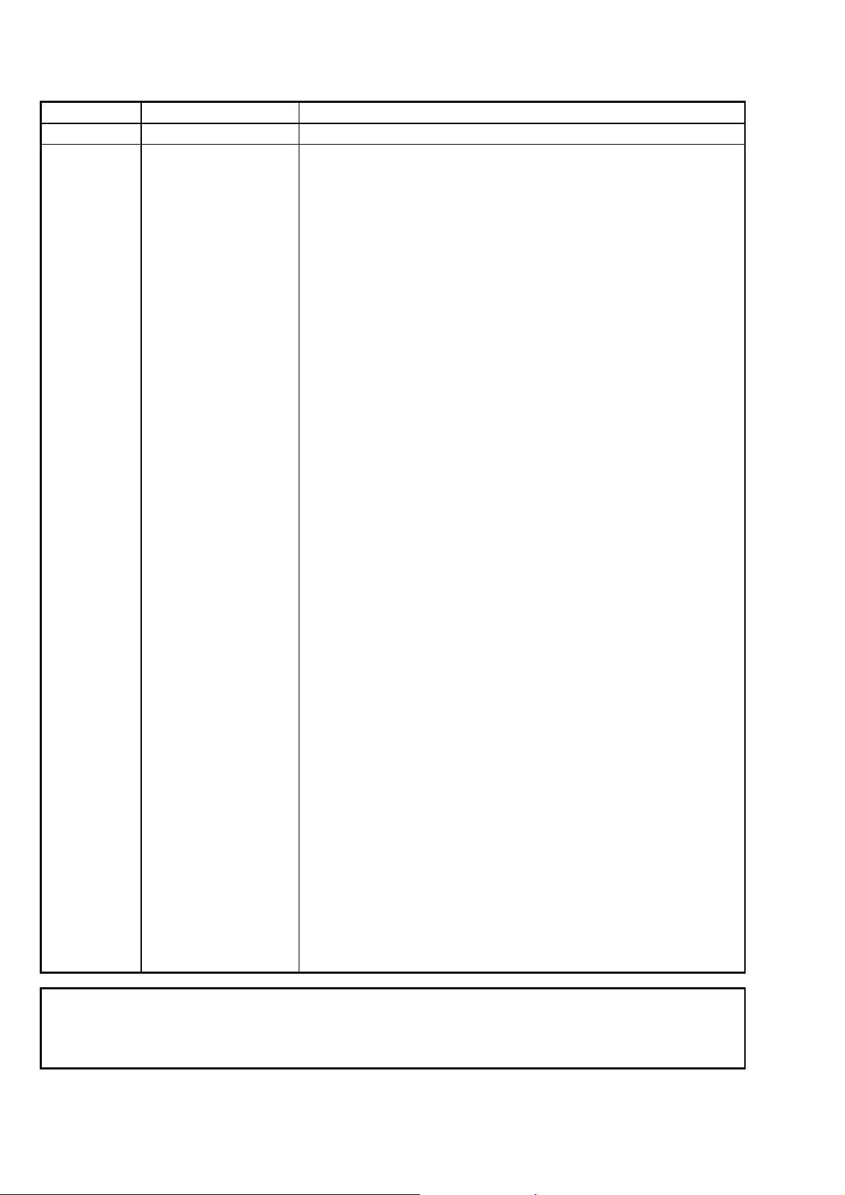
Revisions
*The manual number is given on the bottom left of the back cover.
Print Date *Manual Number Revision
Jul., 2008 IB-(NA)-0800421-A First edition
This manual confers no industrial property rights or any rights of any other kind, nor does it
confer any patent licenses. Mitsubishi Electric Corporation cannot be held responsible for
any problems involving industrial property rights which may occur as a result of using the
contents noted in this manual.
© 2008 MITSUBISHI ELECTRIC CORPORATION
-3

A
CONTENTS
1. Overview········································································································1
2. Performance Specifications ···········································································2
3. Installation······································································································4
3.1 Handling Precautions ···············································································4
3.2 Handling Environment ··············································································4
4. Part Names····································································································5
5. External Wiring·······························································································6
5.1 Wiring Precautions ···················································································6
5.2 External Wiring·························································································7
5.3 Intelligent Function Module Switch Settings ···········································10
6. Comparison between QD62-H01/H02 and QD62 ········································10
7. External Dimensions ····················································································11
-4
A
About the Manuals
The following manuals are also related to this product.
Order them if necessary.
Related Manuals
Manual name
Model QD62, QD62E, QD62D High-Speed Counter Module
User's Manual
This manual describes only specifications of the QD62-H01/H02 that differ from the
specifications of the QD62.
The manual mentioned above covers the usage of the QD62-H01/H02. When referring,
replace the model name “QD62” with “QD62-H01/H02”. For the details of differences
between the QD62-H01/H02 and QD62, refer to Section 6.
Manual No.
(Model code)
SH-080036
(13JL95)
Conformation to the EMC Directive and Low Voltage Instruction
(1) For programmable controller system
To configure a system meeting the requirements of the EMC and Low Voltage Directives when
incorporating the Mitsubishi programmable controller (EMC and Low Voltage Directives compliant) into
other machinery or equipment, refer to Chapter 9 "EMC AND LOW VOLTAGE DIRECTIVES" of the QCPU
User's Manual (Hardware Design, Maintenance and Inspection).
(2) For the product
No additional measures are necessary for the compliance of this product with the EMC and Low Voltage
Directives.
-5
 Loading...