

Mitsubishi QD51-R24, QD51 User Manual


• SAFETY PRECAUTIONS •
(Always read these instructions before using this equipment.)
Before using this product, please read this manual and the relevant manuals introduced in this manual
carefully and pay full attention to safety to handle the product correctly.
The instructions given in this manual are concerned with this product. For the safety instructions of the
programmable controller system, please read the CPU module user's manual.
In this manual, the safety precautions are ranked as "DANGER" and "CAUTION".
DANGER
!
CAUTION
!
Note that the !CAUTION level may lead to a serious consequence according to the circumstances.
Always follow the instructions of both levels because they are important to personal safety.
Please save this manual to make it accessible when required and always forward it to the end user.
Indicates that incorrect handling may cause hazardous conditions,
resulting in death or severe injury.
Indicates that incorrect handling may cause hazardous conditions,
resulting in medium or slight personal injury or physical damage.
[Disposal Precautions]
!
DANGER
• Please refer to the manual for each station concerning the operating status of each station when
communications errors occur in the station. There is danger of accidents due to wrong outputs
or wrong operations.
• When connecting a peripheral device to the CPU module or performing control of a
programmable controller which is being run through a BASIC program, configure an interlock
circuit in the sequence program so that the system overall is operating on the safe side at all
times. Also before exercising other control (program change, operating status change (status
control)) on the running programmable controller, read the manual carefully and fully confirm
safety. Especially for the above control on the remote programmable controller from, an
immediate action may not be taken for programmable controller trouble due to a data
communication fault. In addition to configuring up the interlock circuit in the sequence program,
corrective and other actions to be taken as a system for the occurrence of a data
communication fault should be predetermined between and programmable controller CPU.
• Do not write data to the "System Area" in the intelligent function module's buffer memory.
Also, do not turn ON the "Use Prohibited" output signals among the output signals from the
programmable controller CPU to the intelligent function module.
If data are written to the "System Area" or output in response to "Use Prohibited" signals, there
is danger that the programmable controller system will malfunction.
A - 1 A - 1

[Disposal Precautions]
!
CAUTION
• Do not bunch the control wires or communication cables with the main circuit or power wires, or
install them close to each other. They should be installed 100mm (3.94 in.) or more away from
each other.
Not doing so could result in noise that would cause erroneous operation.
• If a BASIC program is registered in the flash ROM in the module, do not power OFF or reset the
programmable controller CPU at the station where the module is installed during registration.
If it is performed during registration, the data contents in the flash ROM will be erratic and it will
be necessary to reset the setting values, etc. in the buffer memory and register them again in
the flash ROM. It could also cause the module to break down or malfunction.
[Installation Precautions]
!
CAUTION
• Use the programmable controller in an environment that meets the general specifications
contained in the user's manual of the CPU module to use.
Using this programmable controller in an environment outside the range of the general
specifications could result in electric shock, fire, erroneous operation, and damage to or
deterioration of the product.
• While pressing the installation lever located at the bottom of module, insert the module fixing tab
into the fixing hole in the base unit until it stops. Then, securely mount the module with the fixing
hole as a supporting point.
Incorrect loading of the module can cause a malfunction, failure or drop.
When using the programmable controller in the environment of much vibration, tighten the
module with a screw.
• Tighten the screw in the specified torque range.
Undertightening can cause a drop, short circuit or malfunction.
Overtightening can cause a drop, short circuit or malfunction due to damage to the screw or
module.
• Completely turn off the externally supplied power used in the system before mounting or
removing the module.
Not doing so could result in damage to the product.
• Do not directly touch the conductive area or electronic components of the module.
Doing so may cause malfunction or failure in the module.
A - 2 A - 2

[Wiring Precautions]
!
CAUTION
• When turning on the power supply or operating the module after installation or wiring work, be
sure that the module's terminal covers are correctly attached. Not attaching the terminal cover
could result in electric shock.
• External connections shall be crimped or pressure welded with the specified tools, or correctly
soldered.
Imperfect connections could result in short circuit, fires, or erroneous operation.
• Securely insatll the connector to the module.
• Be sure to fix communication cables leading from the module by placing them in the duct or
clamping them.
Cables not placed in the duct or without clamping may hang or shift, allowing them to be
accidentally pulled, which may cause a module malfunction and cable damage.
• When connecting cables, be sure to do so correctly after confirming the type of interface you are
connecting to. If connection is made to a different interface or if wiring is faulty, it could cause
the module or external device to break down.
• Tighten the terminal screws with the specified torque.
If the terminal screws are loose, it could result in short circuits, fire, or erroneous operation.
Tightening the terminal screws too far may cause damages to the screws and/or the module,
resulting in fallout, short circuits, or malfunction.
• When disconnecting the communications cable or power cable that is connected to the module,
do not disconnect it by grasping the cable with your hand and pulling it.
Disconnect cables with connectors attached by taking hold of the connector at the connection
with the module and pulling the connector. For cables connected to a terminal block, remove the
cable after loosening the terminal block screws.
If the cable is pulled while it is connected to the module, it could cause malfunction or damage
the module or the cable.
• Be sure there are no foreign substances such as sawdust or wiring debris inside the module.
Such debris could cause fires, damage, or erroneous operation.
• The module has an ingress prevention label on its top to prevent foreign matter, such as wire
offcuts, from entering the module during wiring.
Do not peel this label during wiring.
Before starting system operation, be sure to peel this label because of heat dissipation.
A - 3 A - 3
[Startup and Maintenance precautions]
!
CAUTION
• Do not disassemble or modify the modules.
Doing so could cause trouble, erroneous operation, injury, or fire.
• Completely turn off the externally supplied power used in the system before mounting or
removing the module. Not doing so could result in damage to the product.
• Do not install/remove the module to/from the base unit, or the terminal block to/from the module
more than 50 times after the first use of the product. (IEC 61131-2 compliant)
Failure to do so may cause malfunction.
• Do not touch the terminals while power is on.
Doing so could cause shock or erroneous operation.
• Switch off all phases of the externally supplied power used in the system when cleaning the
module or retightening the terminal or module fixing screws.
Not doing so could result in electric shock.
Undertightening of terminal screws can cause a short circuit or malfunction.
Overtightening of screws can cause damages to the screws and/or the module, resulting in
fallout, short circuits, or malfunction.
• Before touching the module, always touch grounded metal, etc. to discharge static electricity
from human body, etc.
Not doing so can cause the module to fail or malfunction.
[Operating Precautions]
!
CAUTION
• When performing control (in particular, changing data, changing a program or changing the
operation status (status control)) of the programmable controller during operation using a BASIC
program, do so only after reading the user's manual thoroughly and taking adequate safety
precautions.
If there are errors when changing data, changing a program or in status control, it could result in
system malfunction, or cause mechanical damage or accidents.
[Disposal Precautions]
!
CAUTION
• When disposing of this product, treat it as industrial waste.
A - 4 A - 4
REVISIONS
The manual number is given on the bottom left of the back cover.
Print Date Manual Number Revision
Apr., 2000 SH(NA)-080089-A
Sep., 2000 SH(NA)-080089-B
First printing
Addition
Section 1.3, Section 2.3, 2.3.1, 2.3.2, 2.4
Dec., 2003 SH(NA)-080089-C
Correction
Section 2.1, 6.2
Oct., 2004 SH(NA)-080089-D
Correction
SAFETY PRECAUTIONS, About Manuals, Conformation to the EMC
Directive and Low Voltage Instruction, About the Generic Terms and
Abbreviations, Chapter 1, Section 2.1, 2.3, 2.4, 2.5, Section 3.1, 3.2.1,
3.3.2(2), 3.8.1, Section5.1, 5.5.1
Term change
Feb., 2006 SH(NA)-080089-E
Correction
SAFETY PRECAUTIONS, About Manuals, Conformation to the EMC
Directive and Low Voltage Instruction, How to read this manual, and
Configuration, Section 1.1 to 1.3, Section 2.1, 2.5, Section 3.1, 3.2.1,
3.3.1, 3.3.3, 3.4, 3.5, 3.5.1 to 3.5.7, 3.6 to 3.8, 3.8.1, 3.8.2, 3.9, 3.10,
3.10.1 to 3.10.3, 3.11, 3.11.1 to 3.11.4, 3.12.1, 3.13.1, 3.13.2,
Section 4.1, 4.2, 4.2.1, 4.2.2, 4.3, 4.3.2, 4.4.1, 4.4.5, 4.5, 4.5.3, 4.5.4,
4.8.2, Section 5.2 to 5.5, 5.5.2, 5.6.1, 5.6.2, Section 6.1, 6.2,
Appendix-1, Appendix-2, Appendix-2.1, Appendix-3
Deletion
Appendix-2.2 (incorporated into Appendix-2.1)
Oct.,2006 SH(NA)-080089-F
Correction
SAFETY PRECAUTIONS, Section 2.1
Aug.,2008 SH(NA)-080089-G
Change of a term
"PLC" was changed to "programmable controller".
Correction
SAFETY PRECAUTIONS, Compliance with the EMC and Low Voltage
Directives, About The Generic Terms and Abbreviations, Section 1.2,
2.1, 2.3, 2.4, 2.6, 3.1 to 3.3, 5.1, 5.3 to 5.5, 5.6.2, 5.7, 6.2, Appendix-3
Before change After change
GPPW GX Developer
MELSECNET/10H MELSECNET/H
Japanese Manual Version SH-080092-H
This manual confers no industrial property rights or any rights of any other kind, nor does it confer any patent
licenses. Mitsubishi Electric Corporation cannot be held responsible for any problems involving industrial property
rights which may occur as a result of using the contents noted in this manual.
© 2000 MITSUBISHI ELECTRIC CORPORATION
A - 5 A - 5

INTRODUCTION
Thank you for purchasing the MELSEC-Q series programmable controller.
Before using the equipment, please read this manual carefully to develop full familiarity with the functions
and performance of the Q series programmable controller you have purchased, so as to ensure correct use.
CONTENTS
SAFETY PRECAUTIONS..............................................................................................................................A- 1
REVISIONS ....................................................................................................................................................A- 5
CONTENTS....................................................................................................................................................A- 6
About Manuals ...............................................................................................................................................A- 9
Conformation to the EMC Directive and Low Voltage Instruction ................................................................A- 9
How to read this manual, and Configuration .................................................................................................A-10
About The Generic Terms and Abbreviations ...............................................................................................A-11
Meaning of Terms and Their Contents..........................................................................................................A-13
Product Configuration ....................................................................................................................................A-13
1 OVERVIEW 1- 1 to 1- 9
1.1 Operation Overview for QD51 (-R24)..................................................................................................... 1- 2
1.2 Features of QD51 (-R24) ........................................................................................................................ 1- 4
1.3 About the Function Added/Changed to the Function Version B ........................................................... 1- 9
2 SYSTEM CONFIGURATION AND USABLE FUNCTIONS 2- 1 to 2-11
2.1 Application Systems................................................................................................................................ 2- 1
2.2 Combining the Opposite Party's Device and the Programmable controller CPU................................. 2- 4
2.3 For Use in Multiple CPU System ............................................................................................................ 2- 6
2.4 For Use with Redundant CPUs ..............................................................................................................2- 7
2.5 For Use at MELSECNET/H Remote I/O Station.................................................................................... 2- 8
2.6 How to confirm the function version ....................................................................................................... 2-10
3 SPECIFICATIONS 3- 1 to 3-66
3.1 Performance Specifications .................................................................................................................... 3- 1
3.2 RS-232 Interface Specifications .............................................................................................................3- 3
3.2.1 RS-232 connector specifications .....................................................................................................3- 3
3.2.2 RS-232 cable specifications............................................................................................................. 3- 4
3.3 RS-422/485 Interface Specifications ...................................................................................................... 3- 5
3.3.1 RS-422/485 terminal block specifications ....................................................................................... 3- 5
3.3.2 RS-422/485 cable specifications ..................................................................................................... 3- 6
3.3.3 Cautions during data communications with a RS-422/485 line...................................................... 3- 7
3.4 List of Commands and Functions in AD51H-BASIC.............................................................................. 3-10
3.5 QD51 (-R24) Internal Memory ................................................................................................................ 3-16
3.5.1 Program area.................................................................................................................................... 3-18
3.5.2 Buffer memory .................................................................................................................................. 3-20
3.5.3 Common memory............................................................................................................................. 3-23
3.5.4 Expansion register (ED0 to ED1023) ..............................................................................................3-26
A - 6 A - 6

3.5.5 Special register (ED9000 to ED9127) .............................................................................................3-31
3.5.6 Expansion relay (EM0 to EM1023).................................................................................................. 3-35
3.5.7 Special relay (EM9000 to EM9127)................................................................................................. 3-38
3.6 Receive Buffer......................................................................................................................................... 3-41
3.7 List of GX Developer Setting Items for the QD51 (-R24)....................................................................... 3-42
3.8 List of Input/Output Signals From/To the Programmable controller CPU............................................. 3-43
3.8.1 Input (X) detailed explanation .......................................................................................................... 3-45
3.8.2 Output (Y) detailed explanation .......................................................................................................3-49
3.9 Relationship between the QD51 (-R24) Start Condition and the Flash ROM Execution
Program Area .......................................................................................................................................... 3-53
3.10 QD51 (-R24) Operation when the Power is Turned On ...................................................................... 3-54
3.10.1 In the case of the programming mode........................................................................................... 3-54
3.10.2 In the case of the multitask debug mode ...................................................................................... 3-55
3.10.3 In the case of the run mode ........................................................................................................... 3-56
3.11 Running a Task (a created program) ................................................................................................... 3-57
3.11.1 Conditions for permitting running of a task and start conditions................................................... 3-57
3.11.2 Starting by turning the power on or by reset (start condition: START) ........................................ 3-58
3.11.3 Starting by an interrupt from the programmable controller CPU (Start Condition: IT) ................. 3-60
3.11.4 Starting by a start request from another task (Start condition: BOOT, ON)................................. 3-61
3.12 Running a BASIC Program by Multitask Processing........................................................................... 3-63
3.12.1 Multitask processing....................................................................................................................... 3-63
3.13 BASIC Program Priority Order (Priority)............................................................................................... 3-64
3.13.1 Synchronizing execution between BASIC programs (Event control) ........................................... 3-65
3.13.2 Sharing equipment (Resources) by multitasking .......................................................................... 3-66
4 ABOUT QD51 (-R24) FUNCTIONS 4- 1 to 4-24
4.1 List of Functions ...................................................................................................................................... 4- 1
4.2 Communications with a Console / Terminal........................................................................................... 4- 2
4.2.1 Communications with a console ...................................................................................................... 4- 3
4.2.2 Communications with a terminal...................................................................................................... 4- 6
4.3 Printing by a Printer................................................................................................................................. 4-10
4.3.1 Printing from a printer connected to an interface that is not set in the console ............................. 4-11
4.3.2 Printing from a printer connected to the console ............................................................................ 4-13
4.4 Communications with the External Device............................................................................................. 4-14
4.4.1 If data are being sent ....................................................................................................................... 4-14
4.4.2 If data are received........................................................................................................................... 4-15
4.5 Communications with the Programmable controller CPU .....................................................................4-16
4.5.1 ON/OFF data communications by general output (X/Y) ................................................................. 4-17
4.5.2 Reading and writing data from/to buffer memory............................................................................ 4-18
4.5.3 Reading and writing data from/to the programmable controller CPU ............................................ 4-19
4.5.4 Reading and writing data from/to the programmable controller CPU's expansion file register ..... 4-20
4.6 Reading and Writing Data from/to the Buffer Memory of Another Intelligent Function Module/
Special Function Module ........................................................................................................................4-21
4.7 Reading and Writing Clock Data ............................................................................................................ 4-22
4.8 Data Communications Between Tasks ..................................................................................................4-23
4.8.1 ON/OFF data communications by expansion relay (EM) ...............................................................4-23
4.8.2 Data communications by expansion register (ED).......................................................................... 4-24
A - 7 A - 7

4.8.3 Data communications by common memory.................................................................................... 4-24
5 SETTINGS AND PROCEDURES UP UNTIL OPERATION 5- 1 to 5-17
5.1 Handling Precautions .............................................................................................................................. 5- 1
5.2 Settings and Procedures Up Until Operation ......................................................................................... 5- 2
5.3 Names of Parts and Functions ............................................................................................................... 5- 3
5.4 Connection with a Console, Debugger................................................................................................... 5- 4
5.5 Connection with the External Device...................................................................................................... 5- 5
5.5.1 Connecting to the RS-232 interface ................................................................................................ 5- 6
5.5.2 Connecting to the RS-422/485 interface ......................................................................................... 5- 8
5.6 Setting from the GX Developer............................................................................................................... 5-11
5.6.1 I/O assignment settings.................................................................................................................... 5-11
5.6.2 Switch setting for I/O and intelligent function module ..................................................................... 5-12
5.6.3 Intelligent function module interrupt point settings .......................................................................... 5-16
5.7 Maintenance, Checks ............................................................................................................................. 5-17
6 EXCLUSIVE COMMANDS 6- 1 to 6- 2
6.1 Exclusive Command List and Available Devices ................................................................................... 6- 1
6.2 Z(P). YCHECK ........................................................................................................................................ 6- 2
7 TROUBLESHOOTING 7- 1 to 7- 3
7.1 About QD51 (-R24) Status Checks ........................................................................................................7- 1
7.1.1 Checking the LED lighting status, communications error status and QD51 (-R24) switch
setting status .................................................................................................................................... 7- 1
7.1.2 Errors that occur in BASIC............................................................................................................... 7- 3
APPENDIX App- 1 to App- 7
Appendix-1 Comparison of Functions with Previous Modules ................................................................App- 1
Appendix-2 About Use of Programs from Previous Modules ..................................................................App- 2
Appendix 2.1 About use of A1SD51S, AD51H-S3 programs ..............................................................App- 2
Appendix-3 External Dimensions .............................................................................................................App- 6
INDEX Index- 1 to Index- 2
A - 8 A - 8

About Manuals
The following manuals are also related to this product.
In necessary, order them by quoting the details in the tables below.
Related Manuals
Manual Name
AD51H-BASIC Programming Manual (Command)
(Corresponds to the QD51, QD51-R24, A1SD51S, AD51H-S3.)
Explains the commands, how to use the functions and the specifications of AD51H-BASIC.
(Sold separately)
AD51H-BASIC Programming Manual (Debug and Compile)
(Corresponds to the QD51, QD51-R24, A1SD51S, AD51H-S3.)
Explains concerning debugging of AD51H-BASIC, multitasking settings, and compilation
methods.
(Sold separately)
Manual No.
(Model Name Code)
SH-080090
(13JF63)
SH-080091
(13JF64)
Compliance with the EMC and Low Voltage Directives
(1) For programmable controller system
To configure a system meeting the requirements of the EMC and Low Voltage
Directives when incorporating the Mitsubishi programmable controller (EMC and
Low Voltage Directives compliant) into other machinery or equipment, refer to
Chapter 9 "EMC AND LOW VOLTAGE DIRECTIVES" of the QCPU User's
Manual (Hardware Design, Maintenance and Inspection).
The CE mark, indicating compliance with the EMC and Low Voltage Directives, is
printed on the rating plate of the programmable controller.
(2) For the product
No additional measures are necessary for the compliance of this product with the
EMC and Low Voltage Directives.
A - 9 A - 9

How to read this manual, and Configuration
How to use this manual
We will explain concerning the QD51 (-R24) for each purpose of use.
Use this manual for reference for the following contents.
(1) When desiring to know the features, functions and component
parts
(a) When desiring to know the features and functions
• The features of the QD51 (-R24) are described in Chapter 1.
• The common specifications and functions, etc. of the QD51 (-R24) are
described in Chapter 3.
(b) When desiring to know the package contents and system component parts
• The items included in the package when the QD51 (-R24) is purchased are
described in "Product Configuration" before Chapter 1.
• The user should procure parts and materials not included in the package
contents separately.
(2) When desiring to know the processing necessary to get the QD51
(-R24) started
(a) When desiring to know the startup procedure
• An abbreviated sequence of the procedures up to the point when the QD51
(-R24) is operated is described in section 5.2.
(b) When desiring to know about connections with the console debugger
• The connection method is described in section 5.4.
(c) When desiring to know about connection with the opposite party's device
• The connection method for each type of interface is described in section
5.5.
(d) When desiring to know the processing necessary before the QD51 (-R24) is
started up
• Setting of the parameters used in the QD51 (-R24) using GX Developer is
explained in section 5.6.
(3) When desiring to know about program application
When desiring to know about application of the program from the A1SD51S or
AD51H-S3
• Program application is described in section 2.1 of the Appendix.
A - 10 A - 10

About the Generic Terms and Abbreviations
In this manual, unless specially clarified, explanation of the Intelligent
Communications Module using the general names and abbreviated names shown
below.
(1) Generic terms and Abbreviations of Affected Modules
In this manual, programmable controller CPUs, etc. related to the Intelligent
Communications Module are displayed with the following generic terms and
abbreviations. When it is necessary to clarify the relevant model name, the
affected module's model name is included.
Generic Term/Abbreviation Content of Generic terms and Abbreviations
ACPU AnNCPU, AnACPU, AnUCPU
AnACPU
AnNCPU
AnUCPU A2UCPU, A2UCPU-S1, A2USCPU-S1, A2USHCPU-S1, A3UCPU, A4UCPU
AnA/AnU/QnACPU AnACPU, AnUCPU, QnACPU
AnU/QnACPU AnUCPU, QnACPU
QD51 Shows only the QD51.
QD51-R24 Shows only the QD51-R24.
QD51(-R24) Shows both the AD51 and QD51-R24.
QCPU
QCPU-A Q02CPU-A, Q02HCPU-A, Q06HCPU-A
QnACPU
Q/QnACPU QCPU, QnACPU
A2ACPU, A2ACPU-S1, A2ACPUP21/R21, A2ACPUP21/R21-S1, A3ACPU,
A3ACPUP21/R21
A1NCPU, A1NCPUP21/R21, A2NCPU, A2NCPU-S1, A2NCPUP21/R21,
A2NCPUP21/R21-S1, A3NCPU, A3NCPUP21/R21
Q00JCPU, Q00CPU, Q01CPU, Q02CPU, Q02HCPU, Q06HCPU, Q12HCPU, Q25HCPU,
Q02PHCPU, Q06PHCPU, Q12PHCPU, Q25PHCPU, Q12PRHCPU, Q25PRHCPU,
Q02UCPU, Q03UDCPU, Q04UDHCPU, Q06UDHCPU, Q13UDHCPU, Q26UDHCPU,
Q03UDECPU, Q04UDEHCPU, Q06UDEHCPU, Q13UDEHCPU, Q26UDEHCPU
Q2ACPU, Q2ACPU-S1, Q2ASCPU, Q2ASCPU-S1, Q2ASHCPU, Q2ASHCPU-S1,
Q3ACPU, Q4ACPU, Q4ARCPU
A - 11 A - 11
(2) Other Generic terms and Abbreviations
In this manual, intelligent communications module data communications devices,
etc. are explained using the following generic terms and abbreviations. When it is
necessary to indicate clearly what the object of the explanation is, the name /
model name of that item is included.
Generic Term/Abbreviation Content of Generic terms and Abbreviations
Opposite device (external
device)
Intelligent Function Module
Intelligent Function Module
Device
Special Function Module
Buffer Memory
I/F Interface
CH Channel
GX Developer
MELSECNET/10 MELSECNET/10 network system.
MELSECNET/H MELSECNET/H network system.
RS-232 (Interface) RS-232 compatible interface.
RS-422/485 (Interface) RS-422 and RS-485 compatible interface.
YCHECK Abbreviation for Z.YCHECK or ZP.YCHECK.
User's Manual (Hardware) or
Hardware Manual
Programming Manual
(Commands) or Command
Manual
Programming Manual (Debug
and Compile) or Debug and
Compile Manual
Computer, display, measuring instrument, ID module, bar code reader, adjuster or
other intelligent communications module, UC 24, etc. connected to this intelligent
communications module for data communications.
Q series programmable controller module which runs according to commands from
the programmable controller CPU. (Equivalent to a special function module of the A
series programmable controller)
(Examples)
• CC-Link Interface Module
• A/D, D/A Conversion Module
• Ethernet Interface Module
• Serial Communications Module
Buffer memory of the intelligent function module for storing data sent to and received
from the programmable controller CPU (setting values, monitor values, etc.).
A/QnA series programmable controller modules operated by commands from the
programmable controller CPU. (Equivalent to Q series programmable controller
intelligent function modules.)
(Examples)
• CC-Link Interface Module
• A/D, D/A Conversion Module
• High Speed Counter Module
• Ethernet Interface Module
• Computer Link Module, Serial Communications Module
Buffer memory of the intelligent function module for storing data sent to and received
from the programmable controller CPU (setting values, monitor values, etc.).
Generic product name for SWnD5C-GPPW-E, SWnD5C-GPPW-EA, SWnD5CGPPW-EV, and SWnD5C-GPPW-EVA. ("n" means version 4 or later.)
"-A" and "-V" mean "volume license product" and "version-upgrade product"
respectively.
Q Corresponding Intelligent Communications Module User
AD51H-BASIC Programming Manual (Commands)
AD51H-BASIC Programming Manual (Debug and Compile)
's Manual (Hardware)
A - 12 A - 12
Meanings of Terms and Their Contents
The meanings of terms used in this manual and their contents are shown below.
Term Contents
This is a device which connects to the QD51 (-R24) and is used to perform
Console
Debugger
Terminal
Interpreter This is BASIC in a format which processes while executing commands one by one.
Compiler
Multitasking
Run Mode
Programming Mode This mode is used to connect to the console and carry out programming.
Multitask Debug Mode
programming and multitasking settings.
A PC/AT personal computer with the software package installed becomes a console.
Depending on the settings, the console becomes the debugger.
This device connects to the QD51 (-R24) and performs debugging. A PC/AT personal
computer with the software package installed becomes the debugger. The debugger
can check variable values and can edit the program while it is being run.
This connects to the QD51 (–R24) and is used to display the screen and input
characters from the keyboard.
This compiles programs created with the interpreter. It registers the compiled files and
executes them. Compared to the interpreter, its execution speed is on the average 2
or 3 times faster.
This executes multiple programs by time slicing, executing them so that it seems that
they are being executed simultaneously.
This is the mode used when the console is disconnected and the QD51 (-R24) is
being operated independently. It is actually used when this device is being run as a
system.
This mode changes the contents of variables and traces them while executing a
program, and carries out tracing.
Product Configuration
The QD51 (-R24) product configuration is as shown below.
Model Name Product Name Quantity
QD51 Model QD51 Intelligent Communications Module 1
Model QD51-R24 Intelligent Communications Module 1
QD51-R24
Terminal Resistor 330 Ω, 1/4 W (For RS-422 communications) 2
Terminal Resistor 110 Ω, 1/2 W (For RS-485 communications) 2
A - 13 A - 13

1 OVERVIEW
1 OVERVIEW
MELSEC-Q
1
This manual explains the system configuration, performance specifications and
functions of the QD51 / QD51-R24 Intelligent Communications Module.
When applying the following program examples to the actual system, make sure to
examine the applicability and confirm that it will not cause system control problems.
The QD51 (-R24) has the following functions.
(1) BASIC Program-Based Functions
• Sub-CPU Function
Complex numerical calculations and functional calculations can be made with
a BASIC program.
• Monitor Display Function
It can display production conditions, the operating status, details of a
breakdown, etc.
• Key Input Function
The production schedule, production volume, operation, setting data, etc. can
be input.
• Printer Function
Production plans, performances, daily reports, breakdown details, planning
data, inspection results and test performance, etc. can be printed out.
• Data Input Function
Data can be input from a bar code reader or magnetic card reader, etc.
• External Device Connection Function
A computer, etc. can be connected to the RS-232, RS-422/485 interfaces and
data can be sent and received through a BASIC program.
• Clock Function
Clock data of the programmable controller CPU can be read and written.
(2) Offline Programming Function
BASIC programs can be created, corrected, stored to; user FD and printed out
independently by peripheral devices.
(3) Online Programming Function
BASIC programs can be created, run, and corrected from the console.
(4) Multitasking Debugging Function
BASIC programs can be debugged while they are being run.
1 - 1 1 - 1
1 OVERVIEW
MELSEC-Q
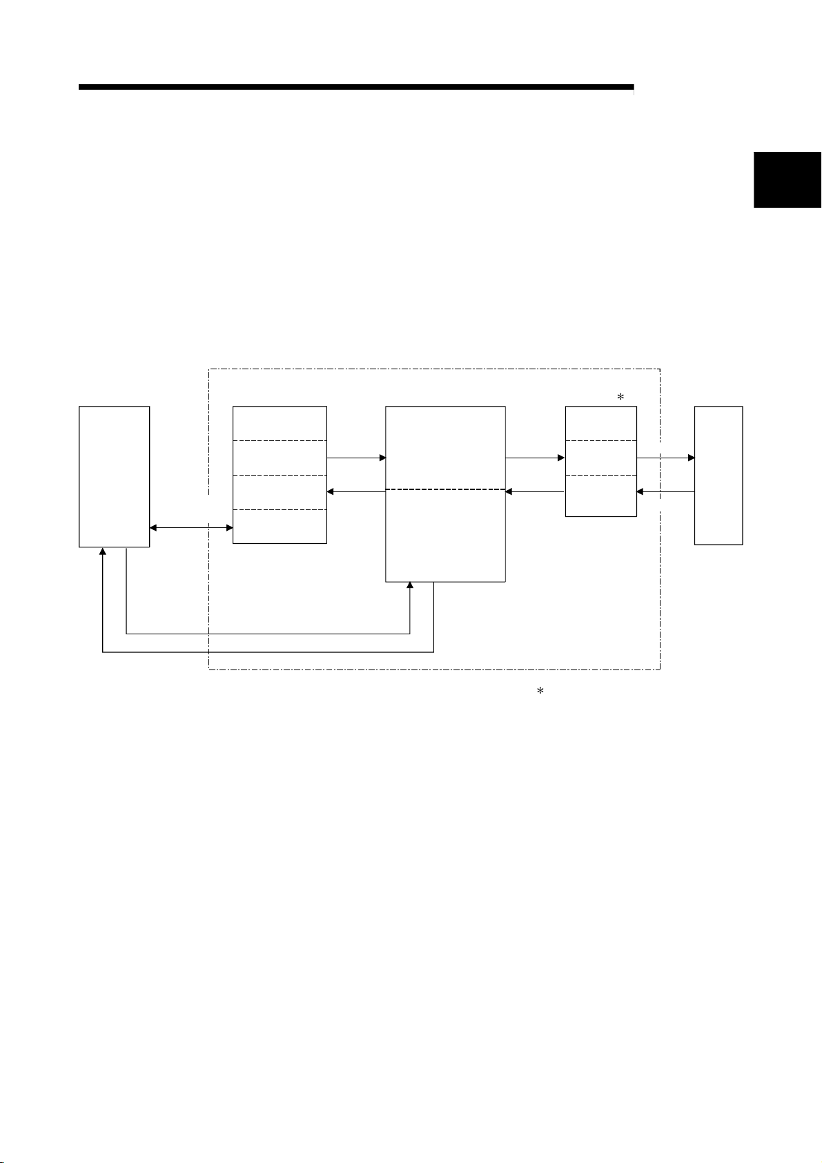
1.1 Operation Overview for QD51 (-R24)
The QD51 (-R24) operates by BASIC programs created by the user.
The BASIC version that can be used by the QD51 (-R24) is AD51H-BASIC, which is
Programmable
controller
Data Sending
/Reception
capable of multitasking processing of up to 2 tasks.
Besides the various calculations that can be carried out by a BASIC program created
by the user,
• Data can be sent to and received from an external device.
• Data can be sent to and received from the programmable controller CPU.
The operation in the QD51 (-R24) when data are sent to or received from an external
device or the programmable controller CPU is as shown below.
Internal Memory BASIC Program
Expansion Relay
Expansion Register
Common Memory
Buffer Memory
• Data reading
• Task start request
Data
reading
Data writing
Task No. 1 Area
Task No. 2 Area
Data
Writing
Data
reading
Interface 1
RS-232
RS-232
RS-422
RS-485
Sending
Reception
External
Device
1
• Interrupt request
• Data writing
1 In the case of the QD51
RS-232 2 Channels
In the case of the QD51-R24
RS-232 1 Channel
RS-422/485 1 Channel
1 - 2 1 - 2

1 OVERVIEW
MELSEC-Q
(1) Sending Data to and Receiving Data from an External Device
The QD51 (-R24) is equipped with the following interfaces.
• QD51
• QD51-R24
Production instructions, production results and other data can be sent to or
received from a personal computer or other external device connected to the RS232 or RS-422/485 interface or the console non-procedurally.
Data such as production results can also be printed out on a printer connected to
the RS-232 interface.
: 2 RS-232 channels
: 1 RS-232 channel, 1 RS-422/485 channel
(2) Sending Data to and Receiving Data from the Programmable
Controller CPU
Through the execution of programmable controller access commands
(PCRD/PCWT), the programmable controller CPU device data can be read and
written.
With the programmable controller access commands, data can also be written to
and read from the buffer memory of a special function module or an intelligent
function module.
1 - 3 1 - 3
1 OVERVIEW
1.2 Features of QD51 (-R24)
Systems which use the QD51 (-R24) have the features shown below.
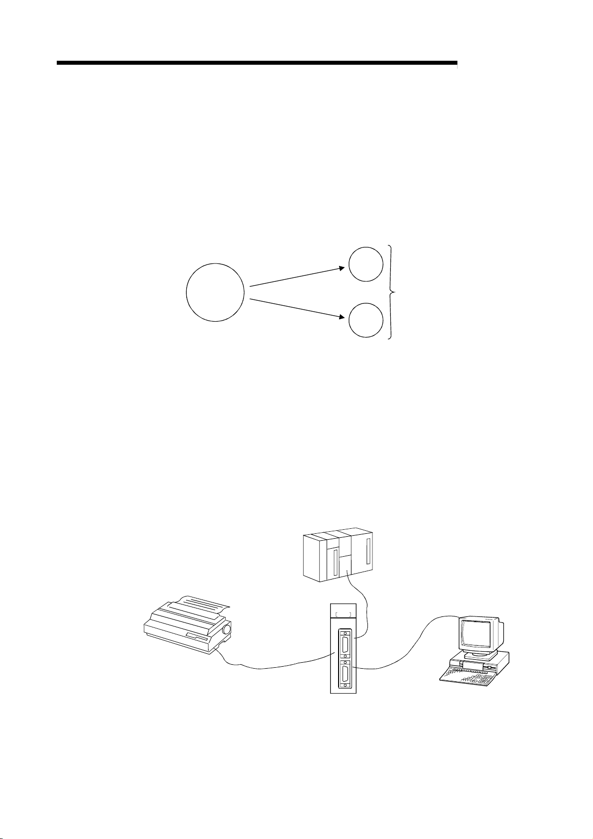
(1) Simultaneous execution of up to two BASIC programs (tasks)
Since multitask processing is possible, BASIC programs can be created by
dividing the control tasks to be done by the QD51 (-R24).
The necessary task is started depending on the control level and the system can
be controlled while exchanging data and synchronizing executions between
tasks.
Controls
executed
in the QD51
(2) Data communications with external devices
<Data communications with external devices>
Non-procedural data communications can be carried out with external devices
connected to the RS-232 and RS-422/485 interfaces.
<Data communications with a console or terminal>
The following data communications can be performed with a console or terminal
connected to the RS232 or RS-422/485 interface.
• Data display to a console or terminal
• Data input to a console or terminal
<Printout on a Printer>
Data can be printed out on a printer connected to the RS-232 interface.
MELSEC-Q
by
ded
i
v
i
D
c
on
pe
y
t
l
o
r
t
Task 1
Task 2
It is possible to create
3 or more BASIC programs.
However, a maximum of
2 tasks (BASIC programs)
can be run simultaneously.
Robot, bar code reader,
thermostat, etc.
QD51-R24
ERR.
RUN
P.RUN
External device
(printer)
PROG
SD
SD
CH.1 CH.2
RD
RD
CH. 1
CH. 2
PC/AT personal computer, etc.
1 - 4 1 - 4

1 OVERVIEW
MELSEC-Q
(3) Data communications with the programmable controller are
possible
Data can be sent to or received from a programmable controller CPU installed
with the QD51(-R24) or the one on the MELSECNET/H or MELSECNET/10
network.
The types of data which can be sent to and received from a programmable
controller CPU are shown below.
1) Device writing and reading in the programmable controller CPU (Max. 960
words/1 time)
2) Writing to and reading from the buffer memory in the intelligent function
module (Max. 960 words/ 1 time).
3) Remote RUN/STOP of the programmable controller CPU.
4) Interrupts to the programmable controller CPU.
(4) File control is possible
Using the console's FD or HD (hard disk), sequential files and random files can
be handled.
However, it is necessary that the console be connected at all times.
<Sequential Files>
These are files in which data can be read and written sequentially and which
enable efficient use of memory.
They are used mainly for operating instruction data files and results files, etc.
<Random Files>
These are files where reading starts from the necessary portion only and only the
necessary portion is written.
This type of file is appropriate for large volume inventory files, instruction data for
operator interfaces, master files, etc.
When reading or writing is done one time, the maximum data size is 256 bytes.
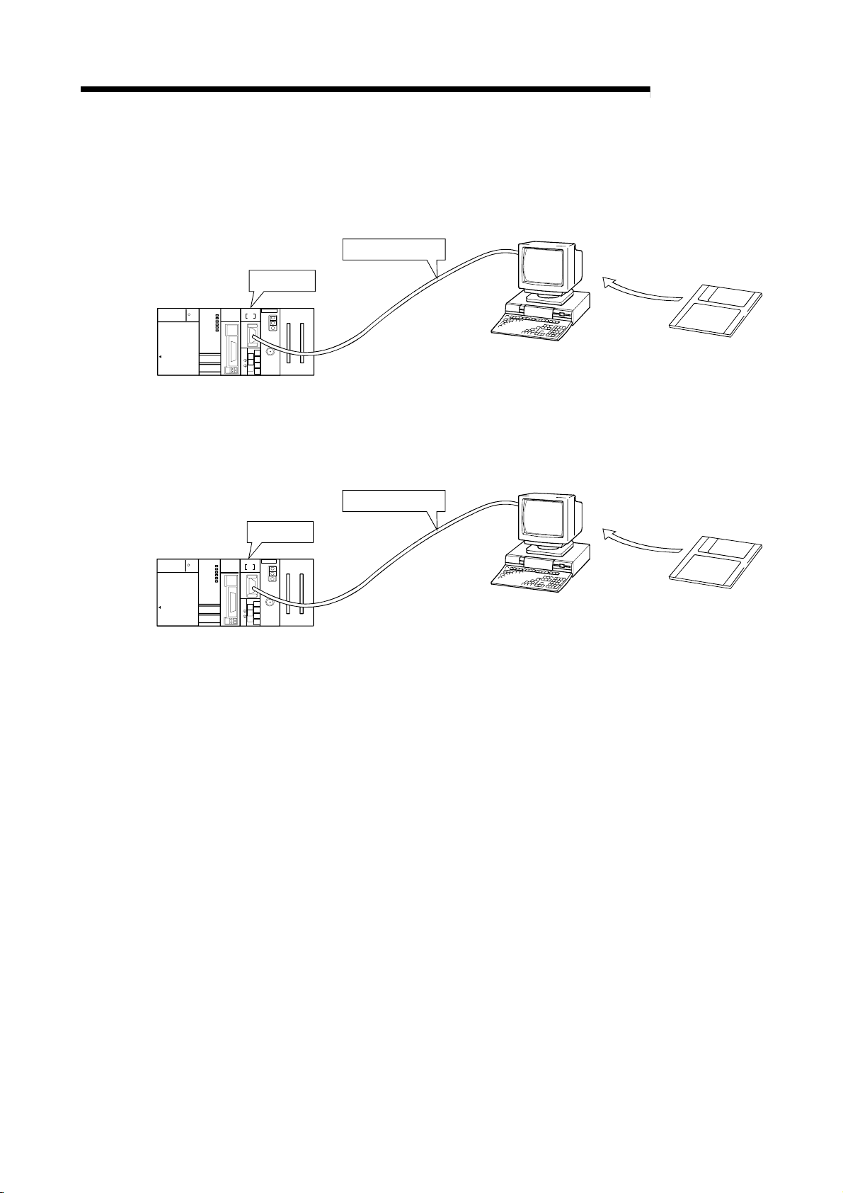
(5) Offline programming with a text editor is possible
A BASIC program can be created offline using a text editor, and the BASIC
program can then be registered.
In offline programming, the edited program cannot be run.
1 - 5 1 - 5
1 OVERVIEW
MELSEC
PULL
MITSUBI SHI
(6) Online programming is possible
By connecting the QD51 (-R24) to a PC/AT personal computer and carrying out
settings at a console, a BASIC program can be edited and debugged.
In the case of programming with a PC/AT personal computer.
RS-232 Cable
QD51-R24
QJ71E71
QD51-R24
Q25HCPU
RUN
ERR.
POWER
MODE
INIT.
COM.ERR
CH2.CH1.
OPEN
RUN
SD
RD
ERR.
10BASE-T
CH1.
USER
BAT.
BOOT
RS-2 3 2
10BASE
CH.3
SDA
1
SG
2
SDB
USB
(FG)
3
RDA
4
(FG)
5
RDB
+
RS- 2 32
12V
6
12G
RS-422
7
/485
(7) Multitask debugging is possible
By connecting the QD51 (-R24) to a PC/AT personal computer and setting a
debugger, debugging can be performed while performing multitask processing.
In the case of programming with a PC/AT personal computer.
MELSEC-Q
User's FD
RS-232 Cable
QD51-R24
MELSEC
PULL
MITSUBI SHI
RUN
ERR.
POWER
MODE
INIT.
COM.ERR
CH2.CH1.
OPEN
RUN
SD
RD
ERR.
10BASE-T
CH1.
USER
BAT.
BOOT
RS-232
10BASE
CH.3
SDA
1
SG
2
SDB
USB
(FG)
3
RDA
4
(FG)
RS- 2 32
5
+
RDB
12V
6
12G
RS-422
7
/485
User's FD
QJ71E71
QD51-R24
Q25HCPU
Multitask debugging is performed by inputting the Debug command from the
debugger. By executing the Debug command, the following can be done.
• The BASIC program for the specified task No. area can be run and terminated.
• The variable values specified in the BASIC program for the specified task No.
area can be read and written.
• Data can be read from and written to the QD51 (-R24)'s internal memory.
• Common events and message port use status displays, etc. can be shared
between BASIC programs.
(8) Both interpreter BASIC and compiled BASIC can be used
By compiling a BASIC program created in interpreter BASIC with the BASIC
compiler, the BASIC processing speed can be markedly increased.
Interpreter BASIC : BASIC in an execution format where the QD51 (-R24)
converts the program to machine language during
execution.
Compiled BASIC : BASIC in the format where the program is compiled (the
commands are converted to machine language) at the stage
when the program is completed and the QD51 (-R24) runs it
in machine language directly.
1 - 6 1 - 6

g
1 OVERVIEW
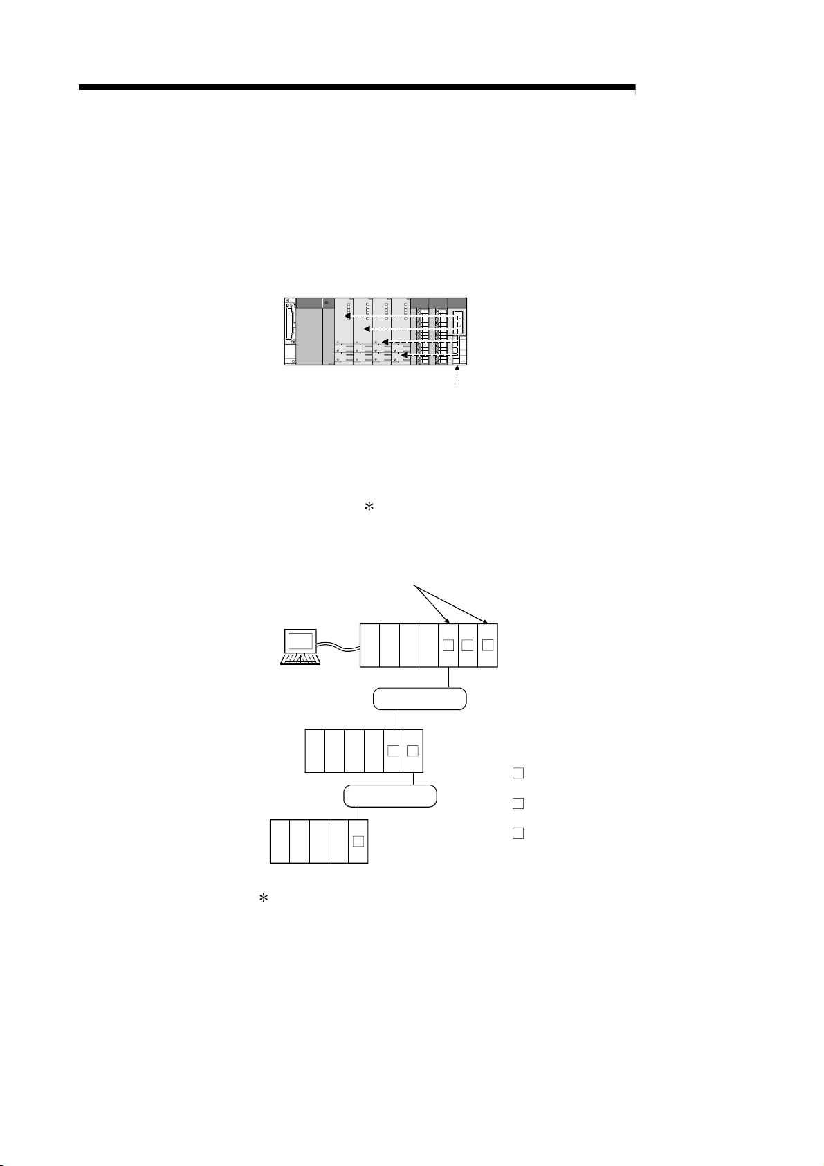
(9) Multiple CPU system compatible functions
(a) If access to a QCPU in a multiple CPU system is done by a BASIC
program, the access destination QCPU is specified, then reading/writing of
device data is executed.
If the QD51 (-R24) is used in a multiple CPU system, set the QCPU that
controls the QD51 (-R24) (called the control CPU) with the GX
Developer.
It is also possible to install the Function Version A QD51 (-R24) in a
multiple CPU system, and only the control CPU (No. 1) can be accessed.
Peripheral Device
QD51 (-R24)'s Control CPU
MELSEC-Q
2 1
QD
51
1) : QCPU No. 1
2) : QCPU No. 2
3) : QCPU No. 3
4) : QCPU No. 4
: Module controlled by QCPU No. 1.
1
: Module controlled by QCPU No. 2.
2
Setting from GX Developer.
2)1) 3) 4) 1
QD51 (-R24)'s Non-control CPUs
(b) If the Function Version B QD51 (-R24) is used in a multiple CPU system,
sending the following types of data to and receiving them from the QD51
(-R24) can be done.
1) It is possible for the control CPU to read data from and write them to
the buffer memory. It is possible to use the I/O signals as the output to
contact and output signal.
2) It is possible for a non control CPU to read the data from the buffer
memory. Input/output signals can be used as contact points.
Non-control CPU
FROM/TO Command
Dedicated Command
Control CPU
QD51(-R24)
Buffer Memory
FROM Command
Input/Output Signal
used as a contact point.
Input/Output Signal
used as a contact
point.
Output to an output
nal.
si
X
Y
1 - 7 1 - 7
1 OVERVIEW
MELSEC-Q
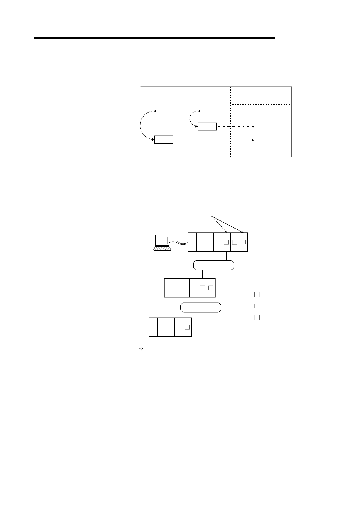
3) It is possible to access the Control CPU / Non Control CPU from the
QD51 (-R24) by a BASIC program.
Non-Control CPU
Control CPU
QD51(-R24)
BASIC Program
(Read/Write)
03FFH03E0H to 03E3H
Data
Device Memory, etc.
Data
Device Memory, etc.
The access destination
QCPU is specified by the
requesting module's I/O No.
If accessing another station by a BASIC program, even if the relay
station or the access station is a multiple CPU system, the Control
CPU and Non Control CPU of the access station can be accessed.
(Example)
Whether the control CPU of the relay module is the same or different,
it is possible to access the other station.
Peripheral
Device
Setting from GX Developer.
Relay Station
Access Station
2)1) 3) 4)
Source Station
2)1) 3) 4)
MELSECNET/ H
2
2)1) 3) 4)
MELSECNET/ H
2 2
1 2
Relay Module: MELSECNET/ H Network Module
1'
1) : QCPU No. 1
2) : QCPU No. 2
3) : QCPU No. 3
4) : QCPU No. 4
1
1'
2
: Relay module controlled
by QCPU No. 1.
: QD51 (-R24) controlled
by QCPU No. 1.
: Relay module controlled
by QCPU No. 2.
The relay module's object during other station access is as follows.
• MELSECNET/H, MELSECNET/10 Network Module
• Q Series C24
• Ethernet Interface Module
If a Function Version A module is included in the relay modules, only
the control CPU can be accessed.
1 - 8 1 - 8

1 OVERVIEW
1.3 About the Function Added/Changed to the Function Version B
This shows the functions that have been added to or changed in the Function
Version B QD51 (-R24).
Function Function overview Explanatory section
Multiple CPU
system
Compatibility
POINT
When reading device data from or writing them
to a multiple CPU system, it is possible to
access the Control CPU / Non Control CPU
specified by the user.
Refer to Section 2.6 concerning the method for checking the function version.
MELSEC-Q
AD51H-BASIC
Programming Manual,
PCRD/PCWT Command
1 - 9 1 - 9
2 SYSTEM CONFIGURATION AND USABLE FUNCTIONS
MELSEC-Q
2 SYSTEM CONFIGURATION AND USABLE FUNCTIONS
This shows system configurations and the functions that can be used.
2.1 Application Systems
This section describes the applicable systems.
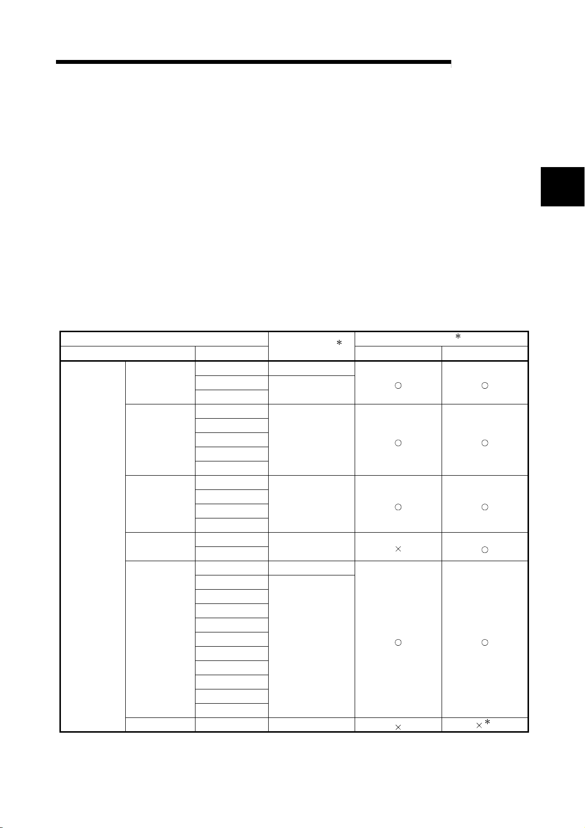
(1) Applicable modules and base units, and No. of modules
(a) When mounted with a CPU module
The table below shows the CPU modules and base units applicable to the
QD51(-R24) and quantities for each CPU model.
Depending on the combination with other modules or the number of
mounted modules, power supply capacity may be insufficient.
Pay attention to the power supply capacity before mounting modules, and if
the power supply capacity is insufficient, change the combination of the
Programmable
controller CPU
Applicable CPU module Base unit2
CPU type CPU model
Basic model
QCPU
High
Performance
model QCPU
Process CPU
Redundant CPU
Universal model
QCPU
Safety CPU QS001CPU N/A
modules.
No. of modules1
Q00JCPU 8
Q00CPU
Q01CPU
Q02CPU
Q02HCPU
Q06HCPU
Q12HCPU
Q25HCPU
Q02PHCPU
Q06PHCPU
Q12PHCPU
Q25PHCPU
Q12PRHCPU
Q25PRHCPU
Q02UCPU 36
Q03UDCPU
Q04UDHCPU
Q06UDHCPU
Q13UDHCPU
Q26UDHCPU
Q03UDECPU
Q04UDEHCPU
Q06UDEHCPU
Q13UDEHCPU
Q26UDEHCPU
24
64
64
53
64
Main base unit Extension base unit
2
3
2 - 1 2 - 1
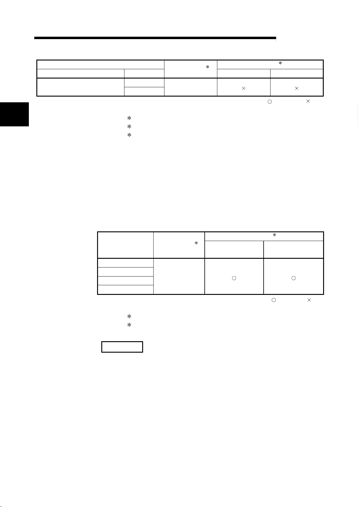
2 SYSTEM CONFIGURATION AND USABLE FUNCTIONS
C Controller
Applicable CPU module Base unit2
CPU type CPU model
Q06CCPU-V
Q06CCPU-V-B
No. of modules1
N/A
2
1 Limited within the range of I/O points for the CPU module.
2 Can be installed to any I/O slot of a base unit.
3 Connection of extension base units is not available with any safety
CPU.
(b) Mounting to a MELSECNET/H remote I/O station
The table below shows the network modules and base units applicable to
the QD51(-R24) and quantities for each network module model.
Depending on the combination with other modules or the number of
mounted modules, power supply capacity may be insufficient.
Pay attention to the power supply capacity before mounting modules, and if
the power supply capacity is insufficient, change the combination of the
Applicable network
QJ72LP25-25
QJ72LP25G
QJ72LP25GE
QJ72BR15
modules.
module
No. of modules1
Up to 64
1 Limited within the range of I/O points for the network module.
2 Can be installed to any I/O slot of a base unit.
MELSEC-Q
Main base unit Extension base unit
: Applicable, : N/A
Base unit2
Main base unit of
remote I/O station
Extension base unit of
remote I/O station
: Applicable, : N/A
REMARKS
The Basic model QCPU module or C Controller module cannot create the
MELSECNET/H remote I/O network.
(2) Support of the multiple CPU system
When using the QD51(-R24) in a multiple CPU system, refer to the QCPU
User’s Manual (Multiple CPU System) first.
(a) Compatible QD51(-R24)
If using the QD51(-R24) on a multiple CPU system, use function version B
of the QD51(-R24) .
2 - 2 2 - 2
2 SYSTEM CONFIGURATION AND USABLE FUNCTIONS
(3) Applicable Software Package
The following software package supports the QD51 (-R24)
(a) Console/debugger software package (essential)
Product Name Model Name Remarks
AD51H-BASIC Software Package SW1IVD-AD51HP-E For PC/AT Personal Computers
CAUTION
MELSEC-Q
To use SW1IVD-AD51HP-E on MicrosoftRWindowsR95 Operating System or
Microsoft
Do not operate on the MS-DOS
R
WindowsR98 Operating System, operate it in the MS-DOSRmode.
R
prompt screen of WindowsR95/WindowsR98.
It will not run correctly.
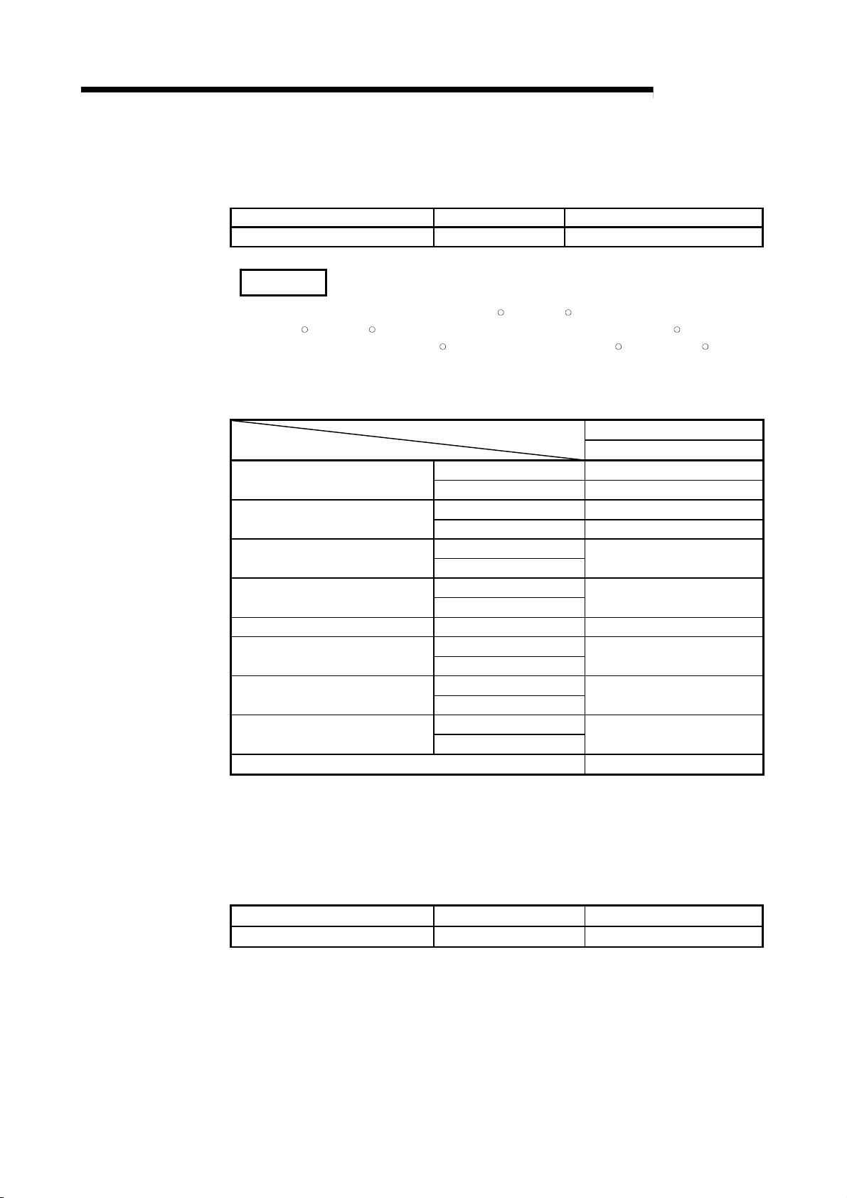
(b) Software package for programmable controllers (Essential)
Q00J/Q00/Q001CPU
Q02/Q02H/Q06H/Q12H/Q25HCPU
Q02PH/Q06PHCPU
Q12PH/Q25PHCPU
Q12PRH/Q25PRHCPU Redundant system Version 8.45X or later
Q02U/Q03UD/Q04UDH/Q06UDHCPU
Q13UDH/Q26UDHCPU
Q13UDEH/Q26UDEHCPU
When installing to a MELSECNET/H remote I/O station Version 6 or later
Single CPU system Version 7 or later
Multiple CPU system Version 8 or later
Single CPU system Version 4 or later
Multiple CPU system Version 6 or later
Single CPU system
Multiple CPU system
Single CPU system
Multiple CPU system
Single CPU system
Multiple CPU system
Single CPU system
Multiple CPU system
Single CPU system Q03UDE/Q04UDEH/Q06UDEH/
Multiple CPU system
Software version
GX Developer
Version 8.68W or later
Version 7.10L or later
Version 8.48A or later
Version 8.62Q or later
Version 8.68W or later
(c) Commercially available compilation software package (necessary only for
compilation)
When using a PC/AT personal computer
Purchase the product Turdo Assembler 5.0.
Turbo Assembler Turbo Assembler Ver.5.0 IBM PC/AT English Version
For Turbo Assembler, contact Borland Software Corporation.
Product Name Model Name Remarks
(4) Connection Cable for Console/Debugger
Refer to Section 5.4 for connection to a console.
2 - 3 2 - 3
2 SYSTEM CONFIGURATION AND USABLE FUNCTIONS
2.2 Combining Programmable Controller CPU(s) with Other Device(s)
This section shows the system configurations and functions which are available when
the QD51 (-R24) is used.
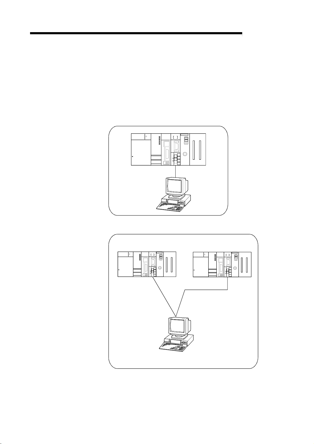
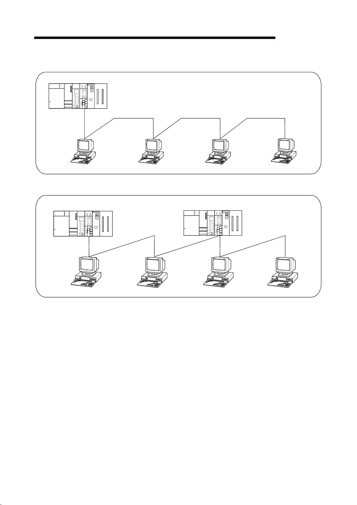
(1) System Configurations
The following shows the system configurations (combinations) for data
communications.
(a) 1:1 system configuration
QJ71E71
MELSEC
PULL
MITSUBISHI
Q25HCPU
RUN
POWER
MODE
INIT.
OPEN
RUN
ERR.
USER
BAT.
BOOT
10BASE
USB
RS-232
ERR.
COM.ERR
SD
RD
10BASE-T
+
12V
12G
QD51-R24
CH2.CH1.
CH1.
RS-232
CH.3
SDA
1
SG
2
SDB
(FG)
3
RDA
4
(FG)
5
RDB
6
RS-422
7
/485
RS-232/422
MELSEC-Q
(b) n:1 system configuration
QJ71E71
QD51-R24
Q25HCPU
MELSEC
PULL
MITSUBI SHI
RUN
ERR.
POWER
INIT.
MODE
COM.ERR
CH2.CH1.
OPEN
RUN
RD
SD
ERR.
10BASE-T
CH1.
USER
BAT.
BOOT
RS-23 2
10BASE
CH.3
SDA
1
SG
2
SDB
USB
(FG)
3
RDA
4
(FG)
RS-232
5
RDB
+
12V
6
12G
RS-422
7
/485
RS-485
MELSEC
PULL
MITSUBI SHI
RUN
ERR.
POWER
MODE
INIT.
COM.ERR
CH2.CH1.
OPEN
RUN
SD
RD
ERR.
10BASE-T
CH1.
USER
BAT.
BOOT
RS-2 32
10BASE
CH.3
SDA
1
SG
2
SDB
USB
(FG)
3
RDA
4
(FG)
RS-232
5
+
RDB
12V
6
12G
RS-422
7
/485
QJ71E71
QD51-R24
Q25HCPU
2 - 4 2 - 4
2 SYSTEM CONFIGURATION AND USABLE FUNCTIONS
QD51-R24
QJ71E71
Q25HCP U
MELSEC
PULL
MITSUBI SHI
RUN
ERR.
POWER
MODE
INIT.
COM.ERR
CH2.CH1.
OPEN
RUN
RD
SD
ERR.
10BASE-T
CH1.
USER
BAT.
BOOT
RS-2 32
10BASE
CH.3
SDA
1
SG
2
SDB
USB
(FG)
3
RDA
4
(FG)
5
RDB
+12V
RS-232
6
12G
RS-422
7
/485
RS-485
(c) 1:n system configuration
(d) m:n system configuration
MELSEC-Q
QJ71E71
QD51-R24
MELSEC
PULL
MITSUBI S HI
ERR.
RUN
POWER
COM.ERR
MODE
INIT.
CH2.CH1.
OPEN
RUN
SD
RD
ERR.
10BASE-T
CH1.
USER
BAT.
BOOT
RS-232
10BASE
CH.3
SDA
1
SG
2
SDB
USB
(FG)
3
RDA
4
(FG)
5
RDB
+12V
RS-232
6
12G
RS-422
7
/485
QJ71E71
QD51-R24
Q25HCPU
Q25HCPU
MELSEC
PULL
MITSUBI SHI
RUN
ERR.
POWER
MODE
INIT.
COM.ERR
CH2.CH1.
OPEN
RUN
SD
RD
ERR.
10BASE-T
CH1.
USER
BAT.
BOOT
RS-232
10BASE
CH.3
SDA
1
SG
2
SDB
USB
(FG)
3
RDA
4
(FG)
5
RDB
12V
+
RS- 2 3 2
6
12G
RS-42 2
7
/485
RS-485 RS-485 RS-485
2 - 5 2 - 5
2 SYSTEM CONFIGURATION AND USABLE FUNCTIONS
2.3 For Use in Multiple CPU System
This section describes the use of the QD51(-R24) in a multiple CPU system.
(1) Making access from a BASIC program to a non-control CPU
When making access from a BASIC program to a non-control CPU, use the
QD51 (-R24) of function version B.
Multiple CPU system
MELSEC-Q
QD51(-R24) of function version B
(2) When other stations to be accessed belong to a multiple CPU system
When accessing a CPU that is not controlling a replay module on the access
target station, use function version B or later for the following modules:
• QD51 (-R24) on local station
• Relay modules
1 and QCPUs on local station, relay station, and accessed
station
(Example)
Whether the control CPU of the relay module is the same or different,
it is possible to access the other station.
Peripheral device
Setting from GX Developer
Relay station
Access Station
Source Station
1) 2) 3) 4)
MELSECNET/ H
2 21) 2) 3) 4)
MELSECNET/ H
21) 2) 3) 4)
The modules used for the routing are MELSECNET/ H network modules
1 2
1'
1) : QCPU No.1
2) : QCPU No.2
3) : QCPU No.3
4) : QCPU No.4
1
1'
2
: Module used for routing, controlled
by QCPU No.1
: QD51(-R24) controlled
by QCPU No.1
: Module used for routing, controlled
by QCPU No.2
1 When accessing other stations, available relay modules are as follows:
• MELSECNET/H and MELSECNET/10 network modules
• Q series C24
• Ethernet interface modules
2 - 6 2 - 6
 Loading...