

Mitsubishi Electric QAHV-N560YA-HPB, QAHV-N560YA-HPB-BS User Manual

HOT WATER HEAT PUMP
MODEL
QAHV-N560YA-HPB(-BS)

CONTENTS
HOT WATER HEAT PUMP
I.
1. Product Specifications .............................................................................................................................. 2
1-1. Specifications................................................................................................................................... 2
1-2. External Dimensions ........................................................................................................................ 3
1-3. Center of Gravity.............................................................................................................................. 4
1-4. Electrical Wiring Diagrams............................................................................................................... 5
1-5. Optional parts .................................................................................................................................. 7
2. Product Data............................................................................................................................................. 12
2-1. Capacity tables ................................................................................................................................ 12
2-2. Sound pressure levels ..................................................................................................................... 22
2-3. Vibration levels ................................................................................................................................ 23
3. Installation................................................................................................................................................. 24
3-1. Selecting the Installation Site........................................................................................................... 24
3-2. Unit Installation ................................................................................................................................ 28
4. System Design.......................................................................................................................................... 29
4-1. Water Pipe Installation ..................................................................................................................... 29
4-2. QAHV Secondary side control ......................................................................................................... 33
5. Wiring Design............................................................................................................................................ 40
5-1. System Configurations..................................................................................................................... 40
5-2. Electrical Wiring Installation............................................................................................................. 41
6. Controller .................................................................................................................................................. 44
6-1. PAR-W31MAA specifications .......................................................................................................... 44
MEES19K001
1
1. Product Specifications
I.1. Product Specifications
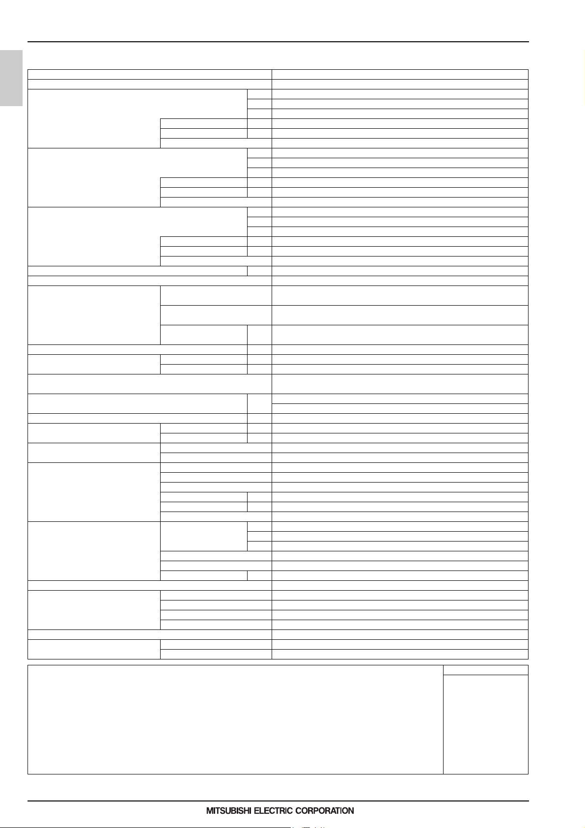
1-1. Specifications
Model QAHV-N560YA-HPB
Power Source 3-phase 4-wire 380-400-415V 50Hz
Capacity *1 kW 40
kcal/h 34400
Power input kW 10.31
Current input A 17.8-16.9-16.3
Capacity *2 kW 40
COP(kW/kW) 3.88
QAHV-N-YA-HPB
Power input kW 10.97
Current input A 20.0-19.0-18.3
COP(kW/kW) 3.65
Capacity *3 kW 40
Power input kW 11.6
Current input A 20.4-19.4-18.7
COP(kW/kW) 3.44
Maximum current input A 33.8
Allowable external pump head 77kPa
Temperature range Inlet water temp 5-63°C
Outlet water temp 55–90°C (when the secondary side control is enabled: 55–80ºC)
Outdoor temp D.B. -25~43°C
Sound Pressure level (measured 1m below the unit in an anechoic room) *1 dB(A) 56
Water pipe diameter and type Inlet mm(in.) 19.05(Rc 3/4"), screw pipe
External finish Acrylic painted steel plate
External dimension H x W x D mm 1837(1777 not including legs) x 1220 x 760
Net weight kg(lbs) 400(882)
Design Pressure R744 MPa 14
Heat exchanger Water-side Copper tube coil
Compressor Type Inverter scroll hermetic compressor
FAN Air flow rate m3/min 220
HIC (HIC: Heat inter-changer) circuit Copper pipe
Protection High pressure protection High pres.Sensor & High pres.Switch at 14MPa(643psi)
Defrosting method Auto-defrost mode (Hot gas)
Refrigerant Type x original charge CO2 (R744) 6.5kg
Notes: Unit converter
*1.Under Normal heating conditions at the outdoor temp, 16°CDB/12°CWB(60.8°FDB/53.6°FWB), the outlet water temperature 65°C(149°F),
and the inlet water temperature 17°C(62.6°F)
*2.Under Normal heating conditions at the outdoor temp, 7°CDB/6°CWB(44.6°FDB/42.8°FWB), the outlet water temperature 65°C(149°F),
and the inlet water temperature 9°C(48.2°F)
*3.Under Normal heating conditions at the outdoor temp, 7°CDB/6°CWB(44.6°FDB/42.8°FWB), the outlet water temperature 65°C(149°F),
and the inlet water temperature 15°C(59.0°F)
*Due to continuing improvements, specifications may be subject to change without notice
*Do not use steel pipes as water pipes.
*Keep the water circulated at all times. Blow the water out of the pipes if the unit will not be used for an extended period time.
*Do not use ground water or well wat er
*Do not install the unit in an environment where the wet bulb temperature exceeds 32°C
*The water circuit must use the closed circuit
*There is a possibility that the unit may abnormally stop when it operates outside its operating range. Provide backup
(ex.boiler start with error display output signal (blue CN511 1-3)) for abnormal stop.
Outlet mm(in.) 19.05(Rc 3/4"), screw pipe
Water MPa 0.5
Air-side Plate fin and copper tube
Maker MITSUBISHI ELECTRIC CORPORATION
Starting method Inverter
Motor output kW 11.0
Case heater kW 0.045
Lubricant PAG
Type x Quantity Propeller fan
Control, Driving mechanism Inverter-control, Direct-driven by motor
Motor output kW 0.92
Inverter circuit Overheat and overcurrent protection
Compressor Overheat protection
Fan motor Thermal switch
Flow and temperature control LEV
Btu/h 136480
kcal/h 34400
Btu/h 136480
kcal/h 34400
Btu/h 136480
41-145.4ºF
131–194ºF (when the secondary side control is enabled: 131–176ºF)
-13~109.4°F
<MUNSELL 5Y 8/1 or similar>
in. 72.3(69.9 not including legs) x 48.0
L/s 3666
cfm 7768
kcal/h =kW x 860
BTU/h =kW x 3,412
cfm =m3/min x 35.31
lbs =kg/0.4536
MEES19K001
2
1. Product Specifications
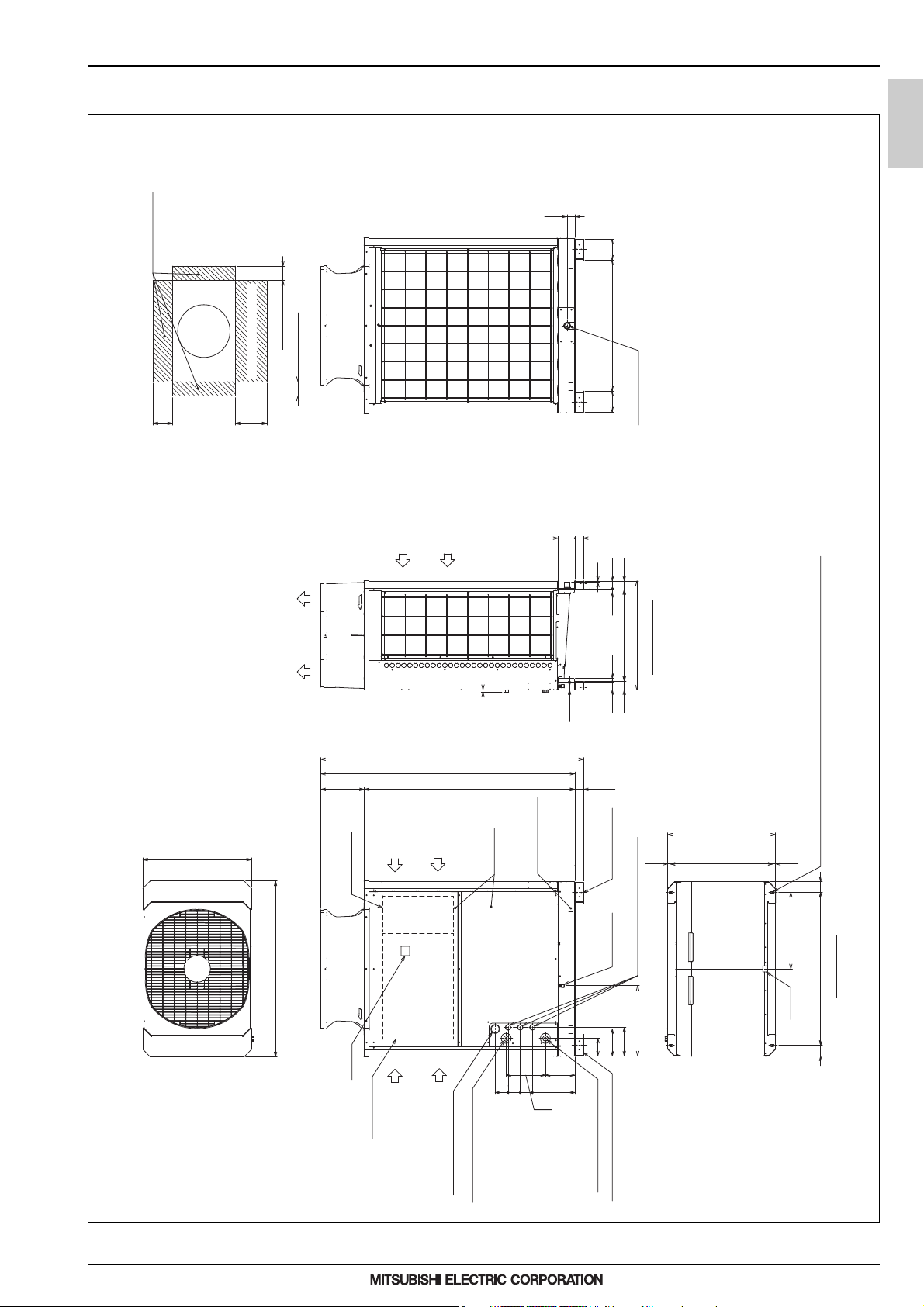
1-2. External Dimensions
QAHV-N560YA-HPB(-BS)
Unit: mm
QAHV-N-YA-HPB
54
VENTILATION SPACE
<PLAN>
SERVICE SPACE
145
(908)
MORE THAN 50
MORE THAN 50
VENTILATION • SERVICE SPACE
MORE THAN 300
MORE THAN 500
118
INTAKE
DISCHARGE
AIR
AIR
9
BACK VIEW
145
DRAIN OUTLET(*1)
ø38.1
(60)
26 5454 26
755
(635)
RIGHT SIDE VIEW
The specification of the product is for the improvement
a previous notice and might change.
760
1220
TOP VIEW
304
<SUB>
CONTROL BOX
DISPLAY
<MAIN>
CONTROL BOX
INTAKE
INTAKE
AIR
AIR
1837
1777
19
1472
SERVICE
PAN EL
HOLE TO PASS ROPE
FOR CARRYING
297
85 9085
274
(24)
122
206
60 60
(60)
ANCHOR BOLT HOLE
(WATER PIPE)
DRAIN OUTLET
ø39 KNOCKOUT HOLE
HOLES FOR TRANSMISSION CABLE
FRONT VIEW
(488)
187
199
(755)
(MOUNTING PITCH)
719(716~722)
530
(*1)
2×2-14×20 OVAL HOLE (without REMOVABLE INSTALLATION LEGS)
2×2-14×31 OVAL HOLE
(ANCHOR BOLT HOLE)
18 18
7474
BOTTOM VIEW
1060(MOUNTING PITCH)
MEES19K001
HOLE FOR POWER SUPPLY
ø62 KNOCKOUT HOLE
HOT WATER OUTLET<Rc3/4B>
WATER INLET<Rc3/4B>
REMOVABLE INSTALLATION LEGS
3
1. Product Specifications
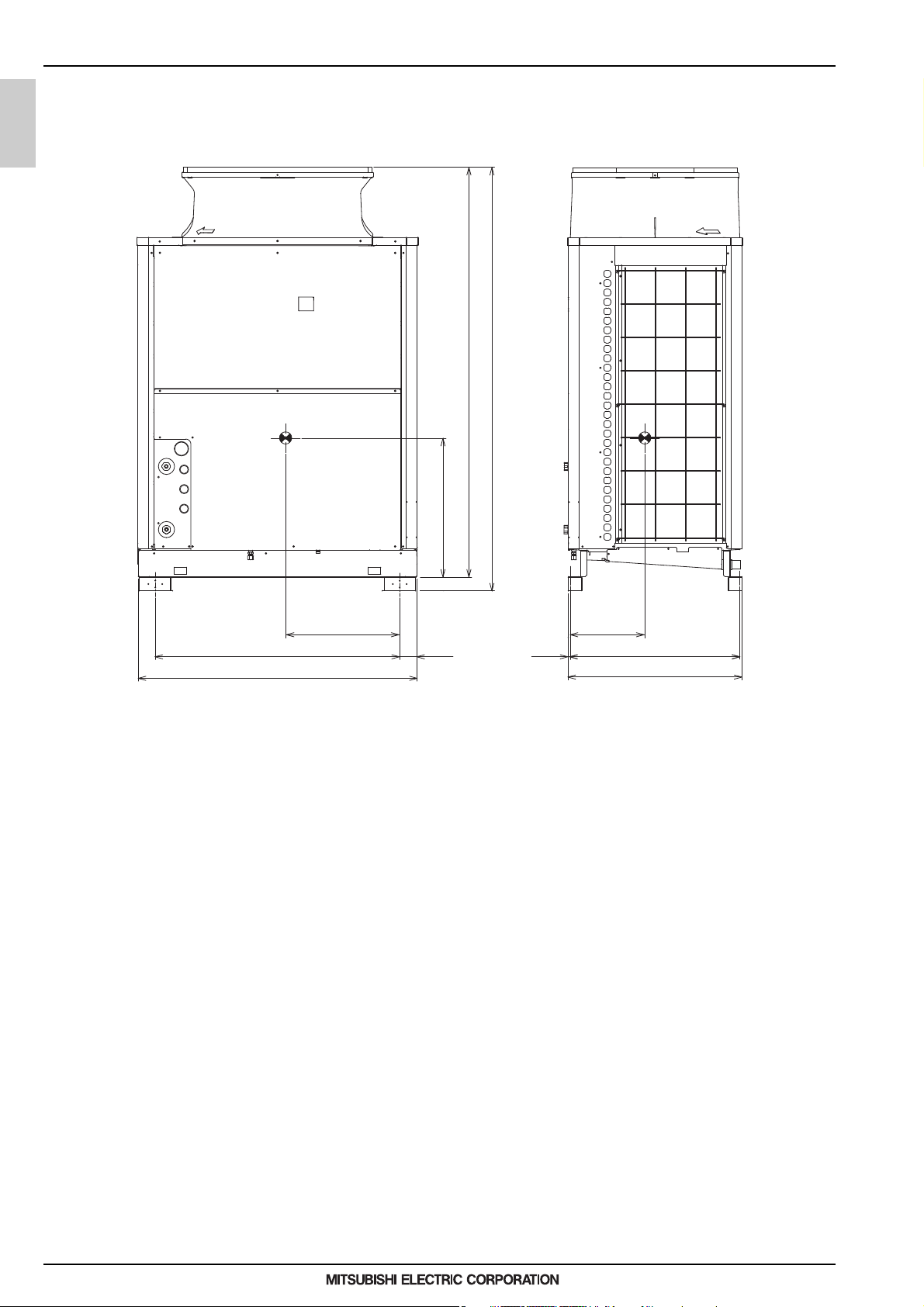
1-3. Center of Gravity
QAHV-N560YA-HPB(-BS)
QAHV-N-YA-HPB
1777
Unit: mm
1837
1060
1208
600
316497
1874 719
755
MEES19K001
4
1. Product Specifications
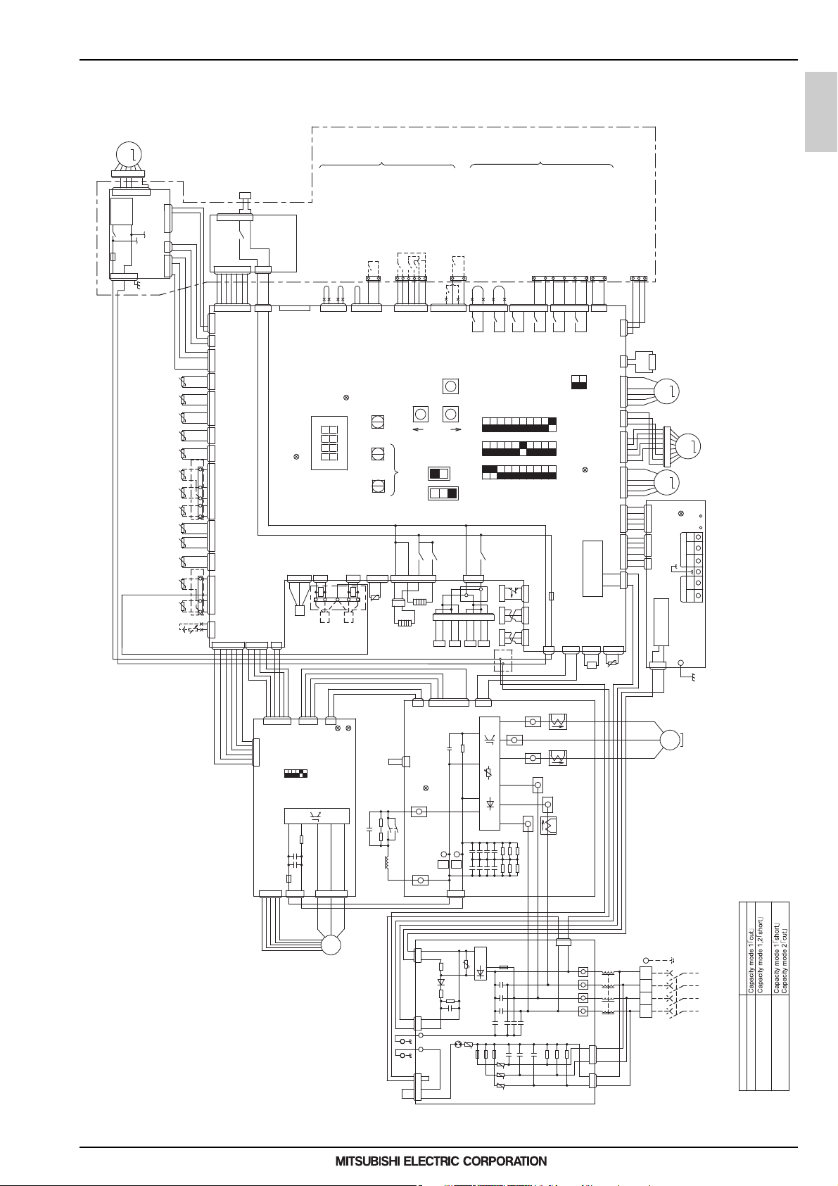
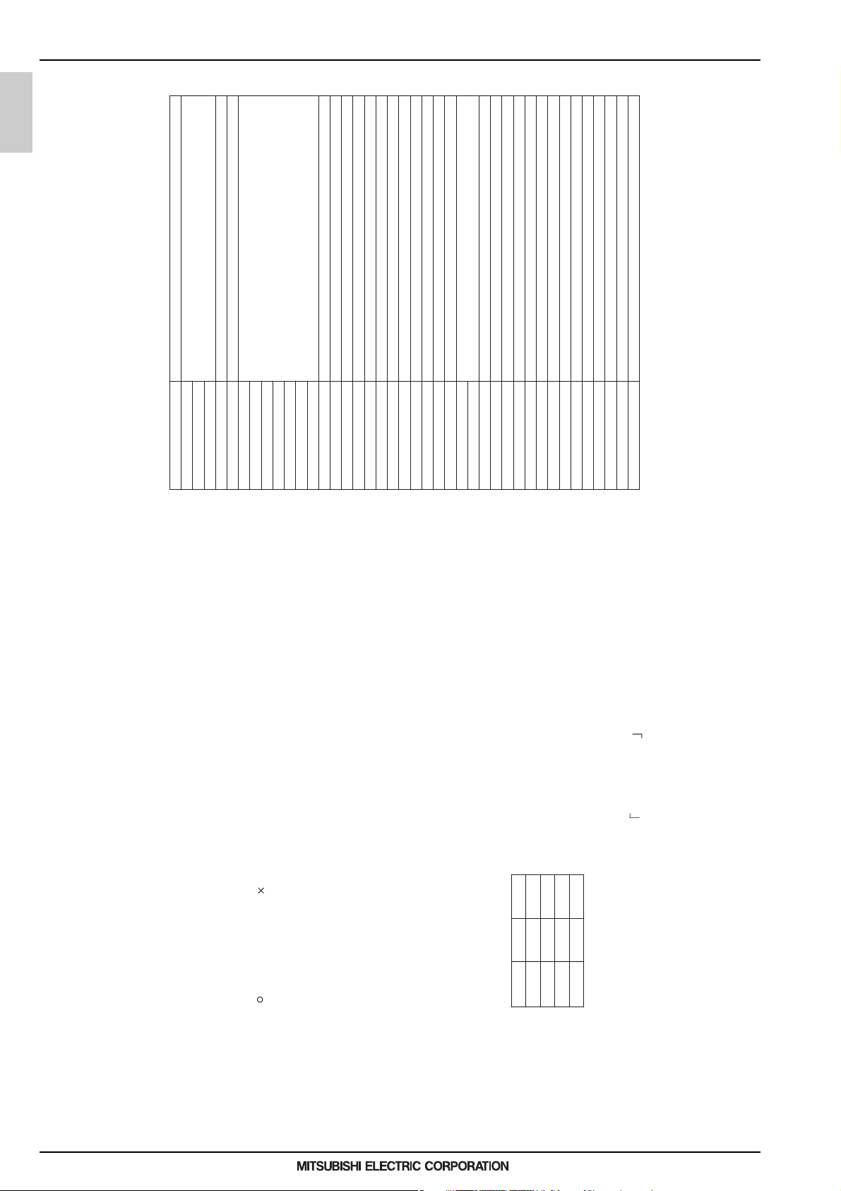
1-4. Electrical Wiring Diagrams
QAHV-N560YA-HPB(-BS)
M
MP1
4
3
216
4
557611
DC280-340V
Rectifier
circuit
X10
F07
AC250V
6.3A T
CND
red
2
3
4
5
5
2
3
CNMF
BS08S-
power board
4
3
2
CNXB1
1234121
CNXC1
blue
CNXA1
Ref temp
Discharge
Compressor
Ref temp
Gascooler
Ref temp
Suction
Compressor
Ref temp
Air hex inlet
Outdoor temp
Water sensor.3
External
TH17
Water sensor.2
External
TH16
Water sensor.1
External
TH15
temp
Water outlet
TH11
temp
Water inlet
TH12TH5 TH1TH4TH9 TH2 TH3
Ref temp
Air hex outlet
TH19TH18
(secondary circuit)
Water sensor
External
1~5V/2~10V
4~2~0mA/0~10V
Analog input
Water temp.setting
*9,10
SV5
654312 7
red
CN33
X37
CN52
CN39
6543 127
213
Relay4-8
board
IT
654312 7
312 4
12
4321
22221111
TB5
6234
30
27 28
3
25 26
34514
1212
TB5
5123
T4
4
321
t° t° t° t° t° t° t° t° t° t° t° t° t°
T1 T2
)
-
(
)
+
(
12
CNRL
red
CNOUT1
red
CNXC1
CNXA2
blue
CN401
CN402
green
CN404
black
CN405
blue
yellow
CN406
CN407
red
CN408
CN409
CN421
CN4A
black
CN61
green
523 614
TERMINAL
543 12
CN105
black
CNAC2
LED4:Power supply
Control Board
CNPL3
black
GND
2
311212
S1
black
CN2A
2431
12
Flow
sensor.1
Capacity mode 2
(short/cut)
Capacity mode 1
(short/cut)
CN142A
black
LED1
CNPL1
CNPL2
green
+12V+12V+12V
R12
14
16
17
15
S3
S2
Flow
sensor
No-Voltage
contact
input
mode(On/Off)
23-24 Run(Run/Stop)
21-24 Low-noise mode
(low noise/by ordinary)
(Forced/Normal)
21
35
23
TB5
1241243
CN142C
SWP1
UP
32-33 Hot-water storage
24
333132
TB6
165432
A(to be
Fan mode
34
3
CN142B
blue
lit while energized
SWU3
LED3:Remote controller
SWU2
SWS2SWS1
SWU1
Unit address setting
yellow
R11
TB4
13
(secondary
circuit)
blue
CN422
t°
TH14
Shell Ref temp
X03
CN502
12 3
3
1
2
6
4
5
H1
12
H2
123456789
System error(Normal/Error)
19-20 Demand(On/Off)
19
234561
CN142D
blue
SWP3
SWP2
prepared)
B(automatic)
External pump
Emergency signal
(for extra heater)
20
TB6
22334576 1
X08
X09
CN512
yellow
ENTER
ONONON
12345678910
OFFOFFOFF
DOWN
123456789
*11
OFF
LOCAL
REMOTE
X02
CN501
81
SV2 SV1SV4 SV3
X01
123
80
63H1
TB2
PSL1PSH1
40
No-voltage
contact
output
Error display output
(secondary circuit)
TB8
1675432 1675432
X06
X07
CN511
blue
312
yellow
CN801
321
red
CN63LS
33
3
22
2
11
1
12
GND GND+5V +5V
CN63HS
TB9
41
External device
connecting terminal
Operation display output
Optional remote controller
connecting terminal
86
737475
87
X04
CN510
ON
12
SW421
OFF
operation
LED2:CPU in
Control
black
CNTYP1
CNTYP2
1212 33
2
(Non-polarized)
RA
RB
TB5
1
blue
CN3A
Power circuit
black
1
Z21
72
X05
10
SW3 SW2 SW1
10987654321
AC250V
3.15A T
F06
red
CNAC
Flow adjustment device
(secondary circuit)
101112
312
CNVOUT
yellow
12
red
CN52C
564321
CNLVC
312
green
CNLVB2
6
5
4
3
CNLVB
red
2
1
564321
CNLVA
blue
5
4
3
CNIT
red
2
1
6
5
4
3
CN62
green
12
pink
312
CNDC
green
CNWP
t°
TB6
72C
CNIT
CNIT
red
243311542
CN102
21
yellow
CNS2
Transmission
2
M
LEV3
8
7
6
5
4
3
2
1
M
LEV1
supply
LED1:Power
TB7
Central
control
TB3
power circuit
13
CN04
red
MVW1
M
TP2
TP1
S
Upper controller
AE-200 connecting terminals
A/M1 B/M2
A/M1 B/M2
Ter m in a l
between units
(TB3-A/M1,B/M2)
Transmission
power board
QAHV-N-YA-HPB
251346
CN80
CN81
green
513462
1
OFF ON
FAN Board
F121
DC700V
4A T
CNSNR
41325
4321
CN82
6
IPM
RSH01,
C152
C151
CNVDC
2314
12
black
blue
CN83
SW001
LED1:Normal operation(lit)
RSH02
7654321
V
U
M
3~
Fan motor
(Heat exchanger)
/Error(blink)
LED4:CPU in operation
*3
R5
C100
R1
DCL
CNINV
W
black
12
2
34
156
7
yellow
CN43
21
CN6
LED1:Normal operation(lit)
/ Error(blink)
4
2
black
72C
SC-P1
1
3
red
SC-P2
red
CN1
3
1
R05
CN5
red
D1
R04
CN4
blue
123 23
CN2
6
5412
123
234156127
CNTYP
RSH1
1234
-
Z5
U
+
Z4
F01,F02,F03
C31
C30
THHS
t°
IGBT
C33
C35
C37
++++++
C32
C34
C36
Diode
Bridge
Noise
Filter
U
F02
F03
AC250V
6.3A T
black
SC-V
R31
++
R30
F04
C10
F01
Z3
Z2
Z1
R33
R32
AC250V
6.3A T
C6
C5
C4
C9
C3
U
U
U
SC-L1
R35
R34
C8
C2
SC-W
SC-U
red
red
C7
SC-L2
C1
white
white
CT22
black
red white
CT12
SC-L3
CT3
black
blackwhite
red
W
3~
MS
V
Motor
U
(Compressor)
INV Board
321
CN3
green
black
R03
TB24
N
TB23
L3
TB22
L2
TB21
L1
CN1B
1
2
3
R01
R02
4
13
2
CN1A
E
L
ELB1
L1 L2 L3 N
TB1
~
50Hz
380/400/415V
3N
power supply
input
mode
Capacity mode table
*
Max capacity operation
Energy saving operation 1
(factory setting)
Energy saving operation 2
CN2
C1
FT-P
FT-N
P
N
R06
+
C17
DSA
MEES19K001
5
1. Product Specifications
QAHV-N-YA-HPB
Ac current sensor
Capacitor (Electrolysis)
DC reactor
Symbol explanation
CT22
CT12
Symbol explanation
CT3
DCL
C100
F01
F02
F03
Fuse
F04
Crankcase heater (for heating the compressor)
F06
Electric heater (Antifreeze)
Electronic expansion valve (Main circuit)
F121
H1
H2
LEV1
F07
Compressor motor
Pump motor
Fan motor
Electronic expansion valve (Injection)
M
MS
MP1
LEV3
Resistance (for Water flow rate sensor 2)
Water flow control valve
MVW1
Resistance (for Water flow rate sensor 3)
Low pressure sensor
High pressure sensor
R11
R12
PSH1
PSL1
Solenoid valve (Defrost)1
Solenoid valve (Defrost)3
Electrical resistance
Solenoid valve (Defrost)2
R1
R5
SV2
SV1
Water flow rate sensor
Solenoid valve (Defrost)4
Solenoid valve (Injection circuit)
SV4
SV5
SV3
S1
Thermistor
High pressure switch
Function setting connector
IGBT temperature
THHS
TH1~5,9,11,12,14
Z21
63H1
Earth leakage breaker
Thermistor
*TH15~18
*S2,3
72C
<ELB1>
Water flow rate sensor
Electromagnetic relay (Inverter main circuit)
* of symbol item is the optional parts, <> is field-supplied parts.
MEES19K001
ON
ONON
OFF
OFFOFF
OFF
OFF
SW421-1 SW421-2
20mA
~5V
~10V
:Terminal block : Connection by cutting the short circuit wire
(no-voltage contact input and remote controller wiring) and wiring of 100V
Press the tab in the middle of the terminals to remove them.
Check that the terminals are securely locked in place after insertion.
3. Faston terminals have a locking function.
4. The symbols of the field connecting terminals are as follows.
1. The broken lines indicate the optional parts,field-supplied parts,and field work.
2. Dashed lines indicate sub box
5. The method of input signal of operation can choose one of optinal remote controller
or greater.Do not place them in the same conduit tube or cabtyre cable as
or no-voltage input.
6. Leave a space of at least 5 cm between the low voltage external wiring
use a separate cabtyre cable for the following wiring.
this will damage the circuit board.
7. When cabtyre cable is used for the control cable wiring,
(a) Optional remote controller wiring
(b) No-voltage contact input wiring
(c) No-voltage contact output wiring
Using the same cabtyre cable may cause malfunctions
and damage to the unit.
(d) Remote water temperature setting
Set the SW421 as shown in the table below.
9. Need to selects either Water temperature setting input signal.
8. Use a contact that takes 12VDC 1mA for no-voltage contact input.
~10V
~
1
0
4
2
Feeding 30mA or more current may damage the circuit board.
10. Use a 4-20mA signal output device with insulation.
11. For prevention of damage of the pump, SWS2 is set in "A"(factory setting).
Note
contact output.
Change the slide switch SWS2 B(automatic) in Test Run.
12. Use a contact that takes 250VAC, 10mA or above, and 1A or below for no-voltage
6
1. Product Specifications
1-5. Optional parts
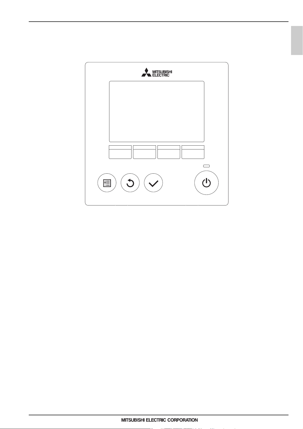
1-5-1. Remote controller PAR-W31MAA
Refer to 6-1. PAR-W31MAA specifications.
QAHV-N-YA-HPB
MEES19K001
7
1. Product Specifications
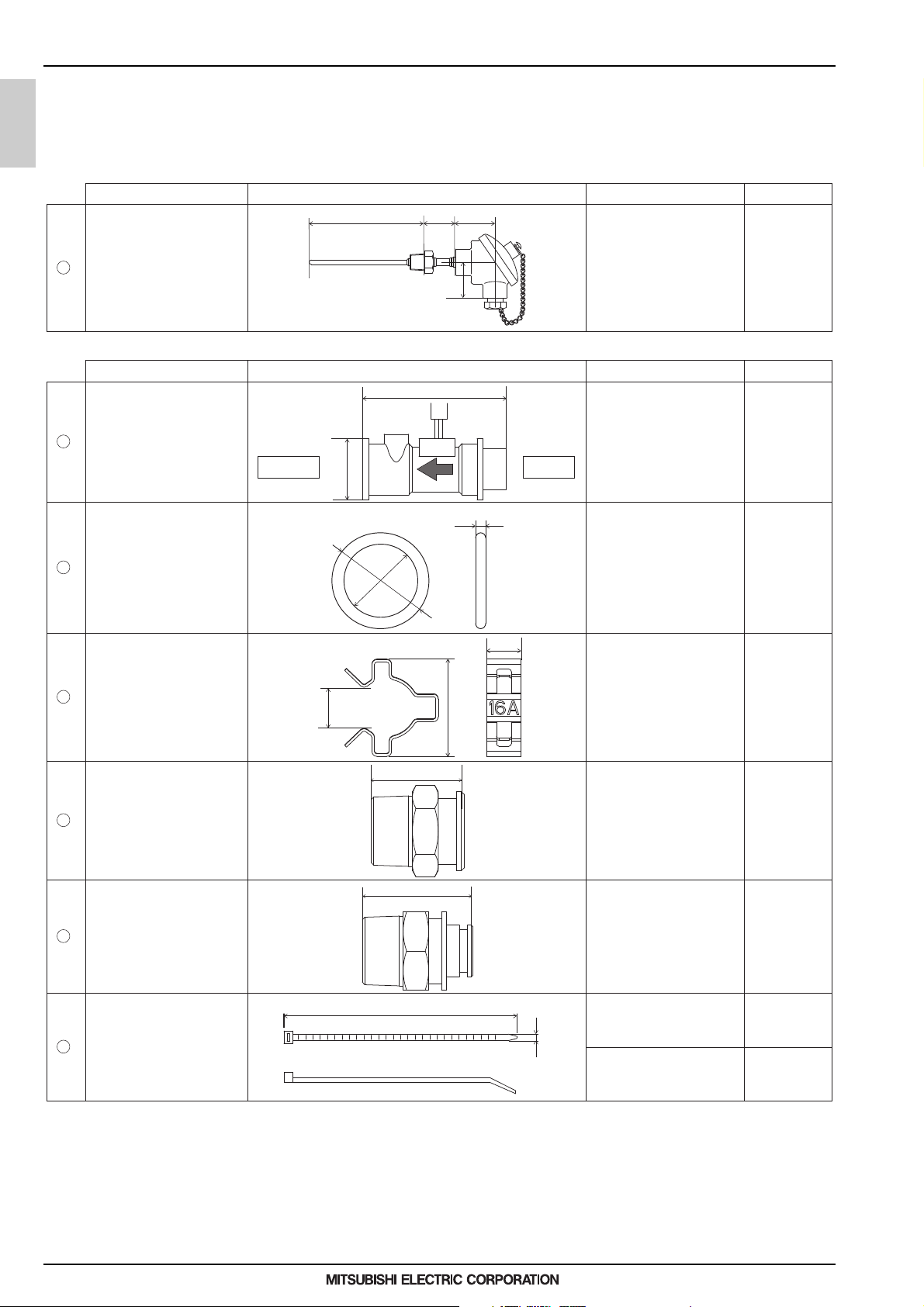
External water temperature sensor TW-TH16-E
Parts Shape Quantity
Thermistor
ABC
D
A: 157 mm
B: 42 mm
C: 54 mm
D: 48 mm
1 pc
Flow sensor kit
Parts Shape Quantity
Flow sensor
A
B
A: 71.5 mm
* 129 mm including the
coupler
B: ø30 mm
Wiring length: 1.9 m
1 pc
O-ring
A
B
C
A: 15.8 mm
B: 2.4 mm
C: 20.6 mm
2 pcs
Quick fastener
A
B
C
A: 38.6 mm
B: 15 mm
C: 14 mm
2 pcs
Coupler 1
(IN-side)
A
Thread: R3/4
Hex 30
A: 36 mm
1 pc
Coupler 2
(OUT-side)
A
Thread: R3/4
Hex 30
A: 43.2 mm
1 pc
Cable tie (2 types)
A
B
Long cable tie
A: 380 mm
B: 4.7 mm
2 pcs
+
1 spare
Short cable tie
A: 100 mm
B: 2.5 mm
1 pc
+
1 spare
IN-side
OUT-side
* The size and length noted are approximate.
1
1
2
3
4
5
6
Specification
Specification
1-5-2. Secondary circuit kit Q-1SCK
This kit contains External water temperature sensor TW-TH16-E and Flow sensor kit for use on the secondary side of hot
water heat pump (QAHV) units. Make sure the following parts are included.
QAHV-N-YA-HPB
MEES19K001
8
1. Product Specifications
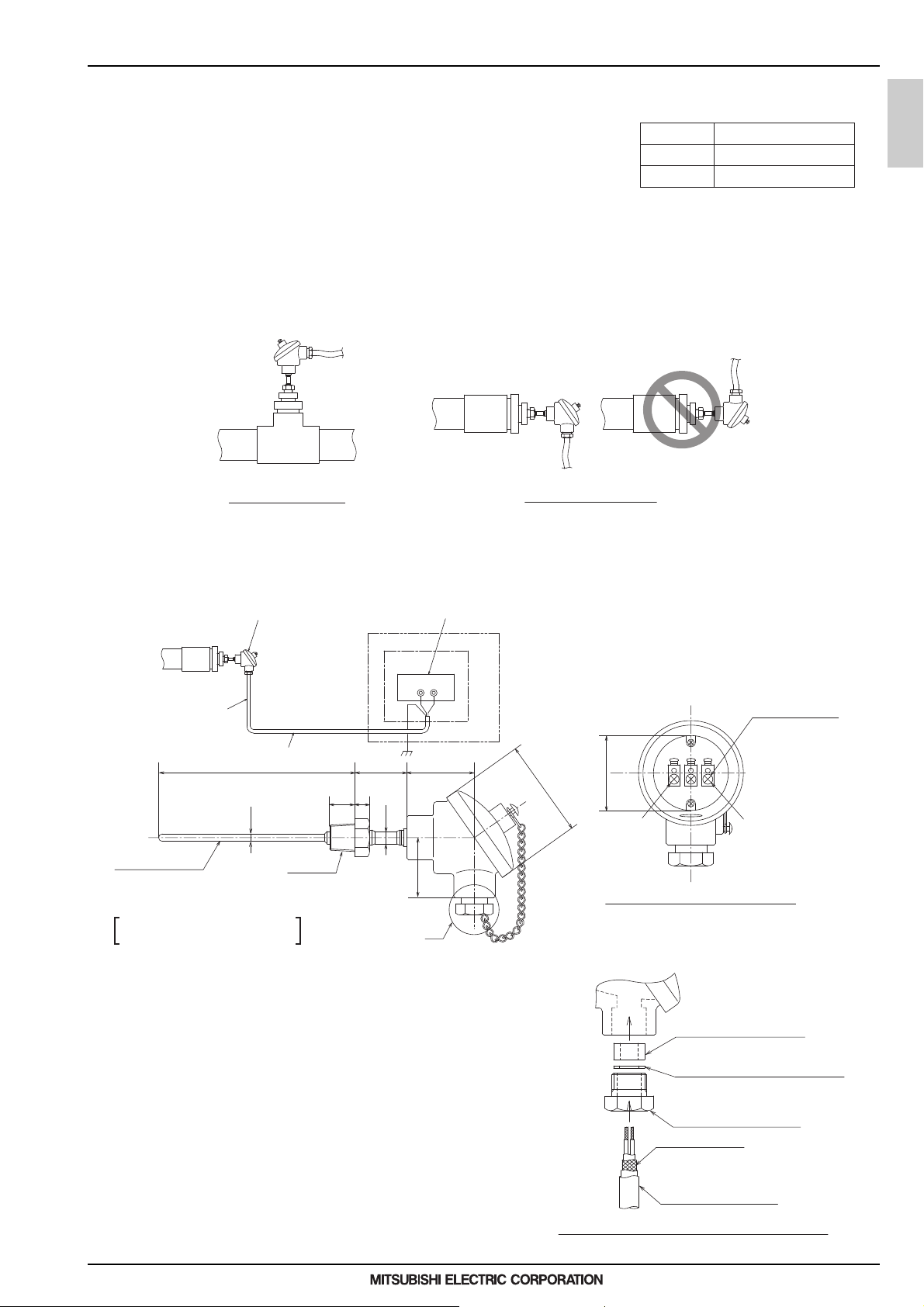
External water temperature sensor TW-TH16
1. Parts that are required to install an external water temperature sensor
A) External water temperature sensor
B) Wiring to connect the sensor and the unit*
C) Wiring terminals to connect the wiring to the sensor and the terminal block
on the unit
(Four for M4 screws)*
* Items B) and C) are field supplied.
2. Installing the external water temperature sensor
Install the external water temperature sensor where the water pipes merge or on the load-side tank.
Install horizontally or vertically on top of the pipe.
When installing horizontally, make sure the wiring faces down.
Wiring specifications
Size
Type
Maximum length
2-core cable (Min.1.25 mm2)
CVVS or CPEVS
20 m
QAHV-N-YA-HPB
Vertical installation
Horizontal installation
3. Wiring the external water temperature sensor
Connect the external water temperature sensor wiring to the terminal block in the control box on the unit as shown in
the figure below.
External water temperature sensor
Sensor wiring
ø6
Sensor
Sensor properties
· Resistance: R = 15 kΩ ± 3% (0°C)
· B-constant: 3460 K
Note
R 1/2
12-pin terminal block in the control box on the unit
(Note) Run the sensor wiring at least 5 cm away from any wiring that
carries a voltage of 100 V or more, and do not put the sensor
wiring in the same conduit tube with it.
T2T1
Control box
5442157
20
12
ø10
48
A
Unit
ø78
M4 screw × 3
Terminal screws
A
BB
50
f)
Terminal block for connection to the sensor
e)
MEES19K001
Connect the sensor wiring to terminals T1 and T2 of the 12-pin
terminal block in the control box on the unit.
Connect the shield to the earth terminal.
Thread the wiring to the external water temperature sensor
through parts b) through d) as shown in the figure at right. Attach
M4 terminals (not supplied) to the wirings, and connect them to
e) and f) (terminals A and B).
After the wiring is connected, securely tighten the tightening
screw d), and then caulk the gap between the wiring a) and the
tightening screw to keep water from entering.
b) Water-sealing rubber
(Internal diameter ø11)
c) Washer (Internal diameter ø12)
d) Tightening screw
(Internal diameter ø15)
Shield (to be cut)
a) Wiring (not supplied)
Detailed view of the area labeled “A” in the figure above
9
1. Product Specifications
Flow sensor kit
1. Tools and materials needed for an installation of the flow sensor
Have the following tools and materials ready before starting.
1 Flow sensor 1 Tightening torque: 50 N·m ± 10%
2 O-ring 2 *2 Only use silicon grease.
3 Quick fastener 2 *3 Select the following type of extension wiring.
4 Coupler 1 (IN-side) 1 Wiring diameter 0.812 mm or larger
5 Coupler 2 (OUT-side) 1 Type CVVS or CPEVS
6 Cable tie (short) 1 Maximum length 20 m
7 Cable tie (long) 1 to 2 *4 Select the type of terminal block that meets the following.
QAHV-N-YA-HPB
1 Screwdriver - Terminal screw diameter of M3.5 or M4
2 Torque wrench (spanner) *1
3 Grease *2
4 Extension wiring *3
5 Terminal block *4
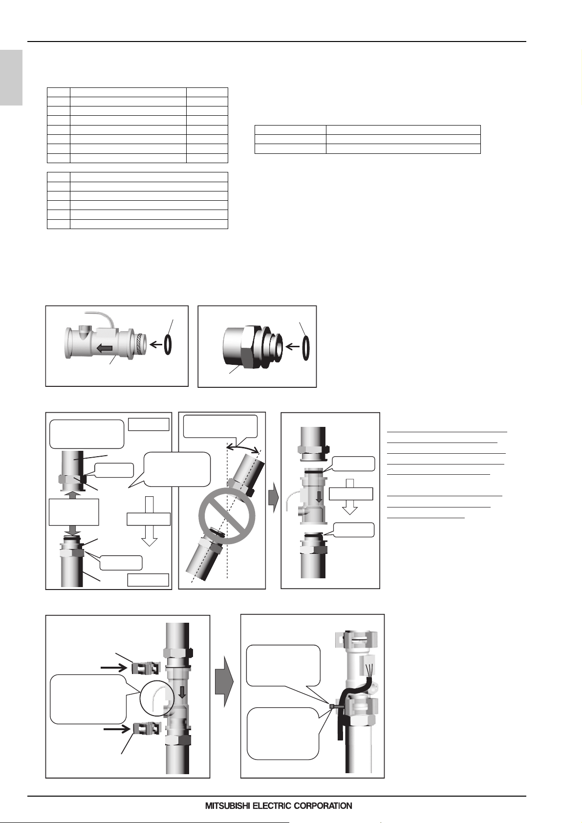
2. Flow sensor installation
Install the flow sensor on the pipe by following steps (1) through (3) below.
Install the flow sensor between the secondary-side pump and the heat exchanger.
Refer to the Installation/Operation Manual of QAHV-N560YA-HPB for details.
(1) Install an O-ring on the flow sensor and coupler 2 (OUT-side).
OUT-side
Materials Quantity *1 Size: HEX 30
Tools and locally procured materials - Usable at or above 15 V
O-ring
IN-side*
- Water-proof
O-ring
Both of the parts shown at left have a groove on the
smaller end. Apply grease to the O-rings, and then fit
them into the groove.
Flow sensor
Coupler 2 (OUT-side)
(2) Connect a coupler to the pipe, and connect the flow sensor.
The degree of incline
should be less than 5
degrees.
Pipe
Screw in.
Coupler 1
Flow sensor
installation
position
(IN-side)
Coupler 2
(OUT-side)
Screw in.
Pipe
Up
The IN-side of the
coupler must face
up.
Flow direction
Down
No more than 5 degrees
of incline allowed
(3) Install the quick fastener on the pipe.
Quick fastener installation
Quick fastener
When installing the
quick fastener, use
caution not to let it
come in contact with
the wiring.
Quick fastener
Hold the wiring with a cable tie.
Place a cable tie
over the protective
tube to hold the
wiring on the pipe.
Thread the cable tie
through the hole on
the quick fastener,
and hold the wiring
in place.
* The end with a smaller bore is the IN-side. Be sure to install
them in the correct orientation.
Attach the coupler to the pipe so that
Coupler 1
(IN-side)
Insert
Flow direction
Insert
Coupler 2
(OUT-side)
the IN-side of the coupler faces up
and the OUT-side of the coupler
faces down. (Water flows from top
to bottom.) The incline of the pipe
should not exceed 5 degrees.
Keep the sensor away from water.
The flow sensor is 71.5 mm long.
Keep an appropriate distance
between the couplers.
Fit the flow sensor to the coupler.
Insert the flow sensor into the couplers,
and then fit the quick fasteners where
the flow sensor and the couplers are
connected to each other. Keep the
quick fasteners out of contact with the
wiring so as not to damage the wiring.
Hold the wiring to the quick fastener
with a (short) cable tie as shown in the
figure to keep the wiring from being
damaged.
Extend the length of the wiring as
necessary, using a terminal block.
Keep the wiring and the terminal block
dry.
MEES19K001
10
1. Product Specifications
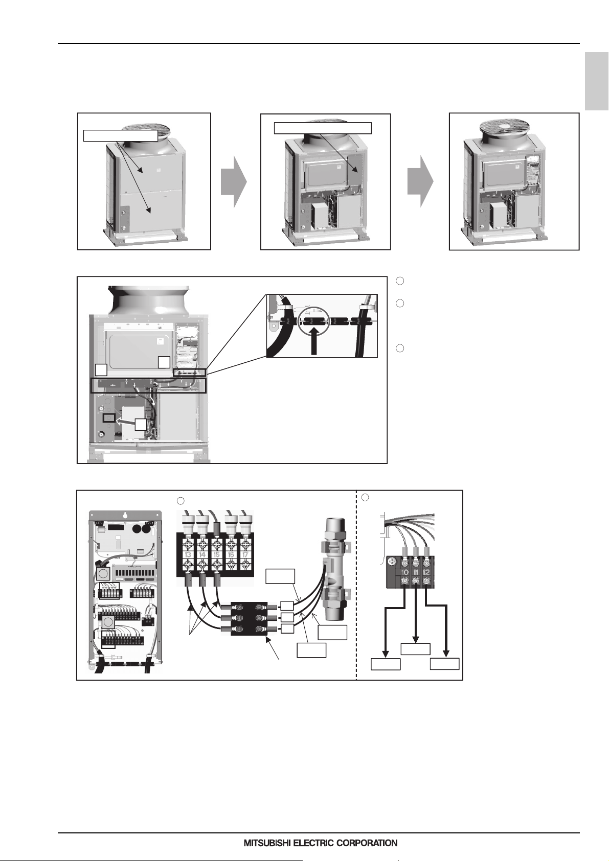
3. Flow sensor wiring connection
Connect the wiring by following steps (1) through (4) below.
(1) Open the panel.
Using a screwdriver, remove the SERVICE PANEL and the CONTROL BOX (SUB) cover.
SERVICE PANEL
(2) Thread the wiring into the unit.
B
C
CONTROL BOX (SUB)
1
Thread the flow sensor wiring through A in the
figure.
2
Hold the wiring with the cable strap inside
the unit indicated as B in the figure to keep
it out of contact with the pipes and other
components.
3
Thread the wiring through the rubber bush
indicated as C in the figure (second one from
the left).
QAHV-N-YA-HPB
A
(3) Connect the wiring.
1
2
1
Flow sensorTerminal block box
Wiring
(not supplied)
Black
15
14
13
White
Terminal block
(not supplied)
Red
* Refer to the Installation/Operation Manual of QAHV-
N560YA-HPB for the detailed explanation on how to
open the part indicated as A and how to route the
wiring indicated as B in the figure.
* Perform wiring work for the flow output adjustment
device and the thermistor at the same time.
2
Flow adjusting device
(Reference)
0-10V
+10V
GND
Connect the flow sensor
wiring to the terminal block
inside the BOX. The numbers
on the wirings correspond to
the numbers on the terminal
block.
Connect each wiring to the
correct terminal.
When done, hold the excess
wiring with the supplied cable
tie (long).
Also, hold the wirings in
place with a cable tie (long)
where indicated as B in the
figure to keep them out of
contact with the pipes and
other components.
(4) Close the panel.
Using a screwdriver, re-place the SERVICE PANEL and the CONTROL BOX (SUB) cover.
4. Cautionary notes
Note the following when performing wiring work.
Turn off the power before performing wiring work to avoid electrocution.
Watch for sharp edges of sheet metal.
Keep external wiring at least 5 cm away from wiring that carries 100 V or higher.
Do not bundle the wiring together with strong current wiring.
Connect wiring in a way that minimizes electrical noise interference. Shield the wiring to minimize external effects.
Install the flow sensor indoors, and insulate it as necessary to keep it from being exposed to subzero temperatures.
Keep the wiring and the terminal block dry.
MEES19K001
11
2. Product Data
2. Product Data
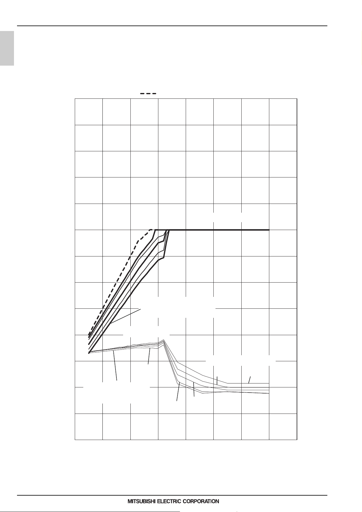
2-1. Capacity tables
2-1-1. Correction by temperature
Outlet water temperature 60~70°C
Energy saving operation 1 mode
QAHV-N560YA-HPB(-BS)
QAHV-N-YA-HPB
65
60
55
50
45
40
35
Capacity
Inlet water temperature 5°C, 400V, unit with a snow hood
Inlet water temperature
5°C~29°C
30
Capacity (kW), Power input (kW)
25
20
15
10
Inlet water temperature
5°C, 9°C, 17°C, 24°C, 29°C
starting from the bottom
5
0
-30 -20 -10 0 10 20 30 40 50
Inlet water temperature
29°C, 24°C, 17°C, 9°C, 5°C
starting from the bottom
Power input
5°C
9°C
17°C
Inlet water temperature
24°C
29°C
29°C
24°C
17°C
9°C
5°C
MEES19K001
Intake air temperature (°C D.B.)
12
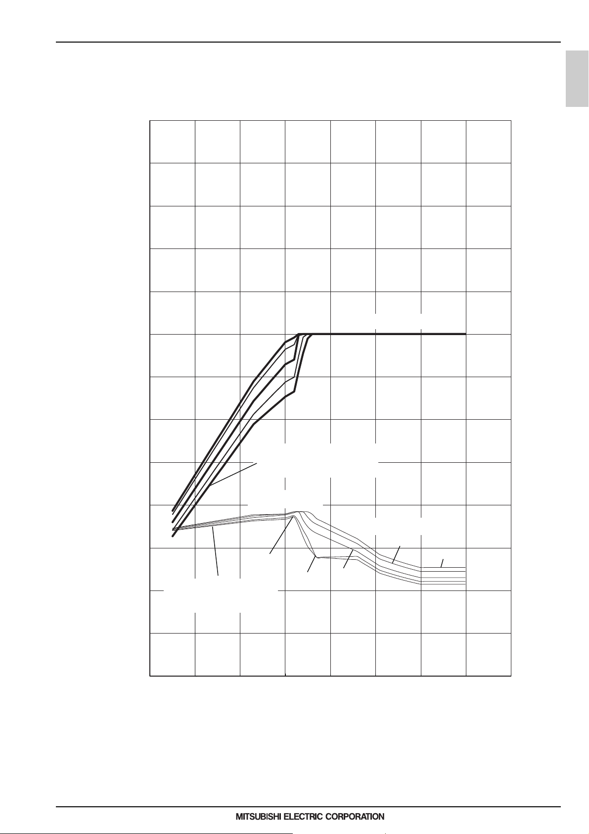
2. Product Data
Outlet water temperature 80°C
Energy saving operation 1 mode
65
60
55
50
45
QAHV-N-YA-HPB
40
35
30
Capacity (kW), Power input (kW)
25
20
15
10
Inlet water temperature
5°C, 9°C, 17°C, 24°C, 29°C
starting from the bottom
Capacity
Inlet water temperature
29°C, 24°C, 17°C, 9°C, 5°C
starting from the bottom
Power input
5°C
9°C
Inlet water temperature
Inlet water temperature
24°C
17°C
5°C~29°C
29°C
29°C
24°C
17°C
5°C
9°C
MEES19K001
5
0
-30 -20 -10 0 10 20 30 40 50
Intake air temperature (°C D.B.)
13
 Loading...