

Page 1

<ORIGINAL>
Hot Water Heat Pump Unit QAHV
Installation/Operation Manual
QAHV-N560YA-HPB
CONTENTS
Safety Precautions ................................................................2
1. Selecting the Installation Site ............................................6
[1] Installation Conditions...................................................6
[2] Installation Space Requirements ..................................7
[3] System installation restrictions......................................9
2. Unit Installation ................................................................10
3. Water Pipe Installation.....................................................11
[1] Schematic Piping Diagram and Piping System
Components ...............................................................11
[2] Notes on Pipe Corrosion............................................. 13
[3] Water Pipe Hole Size and Location ............................ 14
[4] Pipe gradient and air venting valve (Outlet hot water
pipe)............................................................................14
[5] Outlet check valve (When installing multiple units)..... 14
[6] Secondary side control system...................................15
4. System Configurations ....................................................22
[1] Schematic Diagrams of Individual and Multiple
Systems ......................................................................22
[2] Switch Types and the Factory Settings.......................23
[3] Configuring the Settings..............................................25
[4] Air bleeding operation and flow rate adjustment
operation during test run.............................................33
5. Electrical Wiring Installation.............................................51
[1] Main Power Supply Wiring and Switch Capacity ........ 51
[2] Wiring for Configuring Secondary Side Control
System........................................................................53
[3] Cable Connections......................................................54
6. Troubleshooting...............................................................60
[1] Diagnosing Problems for which No Error Codes Are
Available .....................................................................60
[2] Diagnosing Problems Using Error Codes ................... 61
[3] Calling for Service.......................................................66
7. Operating the Unit ...........................................................67
[1] Initial Operation...........................................................67
[2] Daily Operation ........................................................... 67
[3] Using the Remote Controller.......................................68
[4] Using the Unit in Sub-freezing or Snowy Conditions .. 79
8. Main Specifications..........................................................80
Thoroughly read this manual prior to use.
Save this manual for future reference.
Some of the items in this manual may not apply to made-to-order units.
Make sure that this manual is passed on to the end users.
Page 2
Safety Precautions
All electric work must be performed by personnel certified by Mitsubishi Electric.
• Thoroughly read the following safety precautions prior to use.
• Observe these precautions carefully to ensure safety.
WARNING
CAUTION
IMPORTANT
Indicates a risk of death or serious injury
Indicates a risk of injury or structural damage
Indicates a risk of damage to the unit or other components in the system
General
WARNING
Do not use refrigerant other than the type indicated in
the manuals provided with the unit and on the
nameplate.
• Doing so may cause the unit or pipes to burst, or result in
explosion or fire during use, during repair, or at the time of
disposal of the unit.
• It may also be in violation of applicable laws.
• MITSUBISHI ELECTRIC CORPORATION cannot be held
responsible for malfunctions or accidents resulting from the
use of the wrong type of refrigerant.
Do not install the unit in a place where large amounts of
oil, steam, organic solvents, or corrosive gases, such as
sulfuric gas, are present or where acidic/alkaline
solutions or sprays containing sulfur are used
frequently.
These substances can compromise the performance of the
unit or cause certain components of the unit to corrode, which
can result in refrigerant leakage, water leakage, injury,
electric shock, malfunctions, smoke, or fire.
Do not try to defeat the safety features of the unit or
make unauthorized setting changes.
Forcing the unit to operate the unit by defeating the safety
features of the devices such as the pressure switch or the
temperature switch, making unauthorized changes to the
switch settings, or using accessories other than the ones
recommended by Mitsubishi Electric may result in smoke,
fire, or explosion.
To reduce the risk of fire or explosion, do not use volatile or
flammable substances as a heat carrier.
To reduce the risk of burns or electric shock, do not touch
exposed pipes and wires.
To reduce the risk of shorting, current leakage, electric shock,
malfunctions, smoke, or fire, do not splash water on electric
parts.
To reduce the risk of electric shock, malfunctions, smoke or
fire, do not operate the switches/buttons or touch other
electrical parts with wet hands.
To reduce the risk of electric shock and injury from the fan or
other rotating parts, stop the operation and turn off the main
power before cleaning, maintaining, or inspecting the unit.
To reduce the risk of burns or frost bites, do not touch the
refrigerant pipes or refrigerant circuit components with bare
hands during and immediately after operation.
Before cleaning the unit, switch off the power.
(Unplug the unit, if it is plugged in.)
To reduce the risk of injury, keep children away while
installing, inspecting, or repairing the unit.
Children should be supervised to ensure that they do not play
with the appliance.
This appliance is not intended for use by persons (including
children) with reduced physical, sensory or mental
capabilities, or lack of experience and knowledge, unless
they have been given supervision or instruction concerning
use of the appliance by a person responsible for their safety.
Keep the space well ventilated. Refrigerant can displace
air and cause oxygen starvation.
If leaked refrigerant comes in contact with a heat source,
toxic gas may be generated.
Always replace a fuse with one with the correct current
rating.
The use of improperly rated fuses or a substitution of fuses
with steel or copper wire may result in fire or explosion.
If any abnormality (e.g., burning smell) is noticed, stop
the operation, turn off the power switch, and consult
your dealer.
Continuing the operation may result in electric shock,
malfunctions, or fire.
Properly install all required covers and panels on the
terminal box and control box to keep moisture and dust
out.
Dust accumulation and water may result in electric shock,
smoke, or fire.
Consult an authorized agency for the proper disposal of
the unit
Refrigerant oil and refrigerant that may be left in the unit pose
a risk of fire, explosion, or environmental pollution.
CAUTION
To reduce the risk of fire or explosion, do not place flammable
materials or use flammable sprays around the unit.
Do not operate the unit without panels and safety guards
properly installed.
2
Page 3
To reduce the risk of injury, do not sit, stand, or place objects
on the unit.
Do not connect the makeup water pipe directly to the
potable water pipe. Use a cistern tank between them.
Connecting these pipes directly may cause the water in the
unit to migrate into the potable water and cause health
problems.
To reduce the risk of adverse effects on plants and animals,
do not place them where they are directly exposed to
discharge air from the unit.
Do not install the unit on or over things that are
vulnerable to water damage.
Condensation may drip from the unit.
The model of heat pump unit described in this manual is not
intended for use to preserve food, animals, plants, precision
instruments, or art work.
To reduce the risk of injury, do not touch the heat exchanger
fins or sharp edges of components with bare hands.
Do not place a container filled with water on the unit.
If water spills on the unit, it may result in shorting, current
leakage, electric shock, malfunction, smoke, or fire.
Always wear protective gears when touching electrical
components on the unit.
Several minutes after the power is switched off, residual
voltage may still cause electric shock.
To reduce the risk of injury, do not insert fingers or foreign
objects into air inlet/outlet grills.
To reduce the risk of injury, wear protective gear when
working on the unit.
Do not release refrigerant into the atmosphere. Collect
and reuse the refrigerant, or have it properly disposed of
by an authorized agency.
Refrigerant poses environmental hazards if released into the
air.
To prevent environmental pollution, dispose of brine in
the unit and cleaning solutions according to the local
regulations.
It is punishable by law not to dispose of them according to the
applicable laws.
The water heated by the heat pump is not suitable for
use as drinking water or for cooking.
It may cause health problems or degrade food.
In areas where temperature drops to freezing during the
periods of non-use, blow the water out of the pipes or fill
the pipes with anti-freeze solution.
Not doing so may cause the water to freeze, resulting in burst
pipes and damage to the unit or the furnishings.
In areas where temperature drops to freezing, use an antifreeze circuit and leave the main power turned on to prevent
the water in the water circuit from freezing and damaging the
unit or causing water leakage and resultant damage to the
furnishings.
Use clean tap water.
The use of acidic or alkaline water or water high in chlorine
may corrode the unit or the pipes, causing water leakage and
resultant damage to the furnishings.
In areas where temperature can drop low enough to
cause the water in the pipes to freeze, operate the unit
often enough to prevent the water from freezing.
Frozen water in the water circuit may cause the water to
freeze, resulting in burst pipes and damage to the unit or the
furnishings.
Periodically inspect and clean the water circuit.
Dirty water circuit may compromise the unit’s performance or
corrodes the unit or cause water leakage and resultant
damage to the furnishings.
Transportation
WARNING
Lift the unit by placing the slings at designated
locations. Support the outdoor unit securely at four
points to keep it from slipping and sliding.
If the unit is not properly supported, it may fall and cause
personal injury.
CAUTION
To reduce the risk of injury, do not carry the product by the PP
bands that are used on some packages.
Installation
WARNING
Do not install the unit where there is a risk of leaking
flammable gas.
If flammable gas accumulates around the unit, it may ignite
and cause a fire or explosion.
To reduce the risk of injury, products weighing 20 kg or more
should be carried by two or more people.
Properly dispose of the packing materials.
Plastic bags pose suffocation hazard to children.
3
Page 4
The unit should be installed only by personnel certified
by Mitsubishi Electric according to the instructions
detailed in the Installation/Operation Manual.
Improper installation may result in refrigerant leakage, water
leakage, injury, electric shock, or fire.
Any additional parts must be installed by qualified personnel.
Only use the parts specified by Mitsubishi Electric.
Take appropriate safety measures against wind gusts and
earthquakes to prevent the unit from toppling over and
causing injury.
Periodically check the installation base for damage.
If the unit is left on a damaged base, it may fall and cause
injury.
Remove packing materials from the unit before operating
the unit. Note that some accessories may be taped to the
unit. Properly install all accessories that are required.
Failing to remove the packing materials or failing to install
required accessories may result in refrigerant leakage,
oxygen starvation, smoke, or fire.
Consult your dealer and take appropriate measures to
safeguard against refrigerant leakage and resultant oxygen
starvation. An installation of a refrigerant gas detector is
recommended.
CAUTION
Do not install the unit on or over things that are
vulnerable to water damage.
When the indoor humidity exceeds 80% or if the drain water
outlet becomes clogged, condensation may drip from the
indoor unit onto the ceiling or floor.
Pipe installation
WARNING
To prevent explosion, do not heat the unit with refrigerant gas
in the refrigerant circuit.
Be sure to install the unit horizontally, using a level.
If the unit is installed at an angle, it may fall and cause injury
or cause water leakage.
The unit should be installed on a surface that is strong
enough to support its weight.
As an anti-freeze, use ethylene glycol or propylene
glycol diluted to the specified concentration.
The use of other types of anti-freeze solution may cause
corrosion and resultant water leakage. The use of flammable
anti-freeze may cause fire or explosion.
All drainage work should be performed by the dealer or
qualified personnel according to the instructions
detailed in the Installation Manual.
Improper drainage work may cause rain water or drain water
to enter the buildings and damage the furnishings.
Check for refrigerant leakage at the completion of
installation.
If leaked refrigerant comes in contact with a heat source,
toxic gas may be generated.
CAUTION
Check that no substance other than the specified
refrigerant (R744) is present in the refrigerant circuit.
Infiltration of other substances may cause the pressure to
rise abnormally high and cause the pipes to explode.
To keep the ceiling and floor from getting wet due to
condensation, properly insulate the pipes.
Electrical wiring
To reduce the risk of wire breakage, overheating, smoke, and
fire, keep undue force from being applied to the wires.
Properly secure the cables in place and provide
adequate slack in the cables so as not to stress the
terminals.
Improperly connected cables may break, overheat, and
cause smoke or fire.
To reduce the risk of injury or electric shock, switch off the
main power before performing electrical work.
Piping work should be performed by the dealer or
qualified personnel according to the instructions
detailed in the Installation Manual.
Improper piping work may cause water leakage and damage
the furnishings.
All electric work must be performed by a qualified
electrician according to the local regulations, standards,
and the instructions detailed in the Installation Manual.
Capacity shortage to the power supply circuit or improper
installation may result in malfunction, electric shock, smoke,
or fire.
To reduce the risk of electric shock, smoke, or fire, install an
inverter circuit breaker on the power supply to each unit.
Use properly rated breakers and fuses (inverter breaker,
Local Switch <Switch + Type-B fuse>, or no-fuse
breaker).
The use of improperly rated breakers may result in
malfunctions or fire.
4
Page 5
To reduce the risk of current leakage, overheating, smoke, or
fire, use properly rated cables with adequate current carrying
capacity.
Keep the unsheathed part of cables inside the terminal
block.
If unsheathed part of the cables come in contact with each
other, electric shock, smoke, or fire may result.
CAUTION
To reduce the risk of current leakage, wire breakage, smoke,
or fire, keep the wiring out of contact with the refrigerant
pipes and other parts, especially sharp edges.
Transportation and repairs
WARNING
Proper grounding must be provided by a licensed
electrician. Do not connect the grounding wire to a gas
pipe, water pipe, lightning rod, or telephone wire.
Improper grounding may result in electric shock, smoke, fire,
or malfunction due to electrical noise interference.
To reduce the risk of electric shock, shorting, or malfunctions,
keep wire pieces and sheath shavings out of the terminal
block.
The unit should be moved, disassembled, or repaired
only by qualified personnel. Do not alter or modify the
unit.
Improper repair or unauthorized modifications may result in
refrigerant leakage, water leakage, injury, electric shock, or
fire.
CAUTION
To reduce the risk of shorting, electric shock, fire, or
malfunction, do not touch the circuit board with tools or with
your hands, and do not allow dust to accumulate on the
circuit board.
IMPORTANT
To avoid damage to the unit, use appropriate tools to install,
inspect, or repair the unit.
To reduce the risk or malfunction, turn on the power at least
12 hours before starting operation, and leave the power
turned on throughout the operating season.
Recover all refrigerant from the unit.
It is punishable by law to release refrigerant into the
atmosphere.
Do not unnecessarily change the switch settings or
touch other parts in the refrigerant circuit.
Doing so may change the operation mode or damage the
unit.
To reduce the risk of malfunctions, use the unit within its
operating range.
Do not switch on or off the main power in a cycle of
shorter than 10 minutes.
Short-cycling the compressor may damage the compressor.
To maintain optimum performance and reduce the risk of
malfunction, keep the air pathway clear.
After disassembling the unit or making repairs, replace
all components as they were.
Failing to replace all components may result in injury, electric
shock, or fire.
If the supply cord is damaged, it must be replaced by the
manufacturer, its service agent or similarly qualified persons
in order to avoid a hazard.
To ensure proper operation of the unit, periodically
check for proper concentration of anti-freeze.
Inadequate concentration of anti-freeze may compromise the
performance of the unit or cause the unit to abnormally stop.
Take appropriate measures against electrical noise
interference when installing the air conditioners in
hospitals or facilities with radio communication
capabilities.
Inverter, high-frequency medical, or wireless communication
equipment as well as power generators may cause the air
conditioning system to malfunction. Air conditioning system
may also adversely affect the operation of these types of
equipment by creating electrical noise.
Check the water system, using a relevant manual as a
reference.
Using the system that does not meet the standards (including
water quality and water flow rate) may cause the water pipes
to corrode.
To reduce the risk of power capacity shortage, always use a
dedicated power supply circuit.
This appliance is intended to be used by expert or trained
users in shops, in light industry and on farms, or for
commercial use by lay persons.
5
Page 6
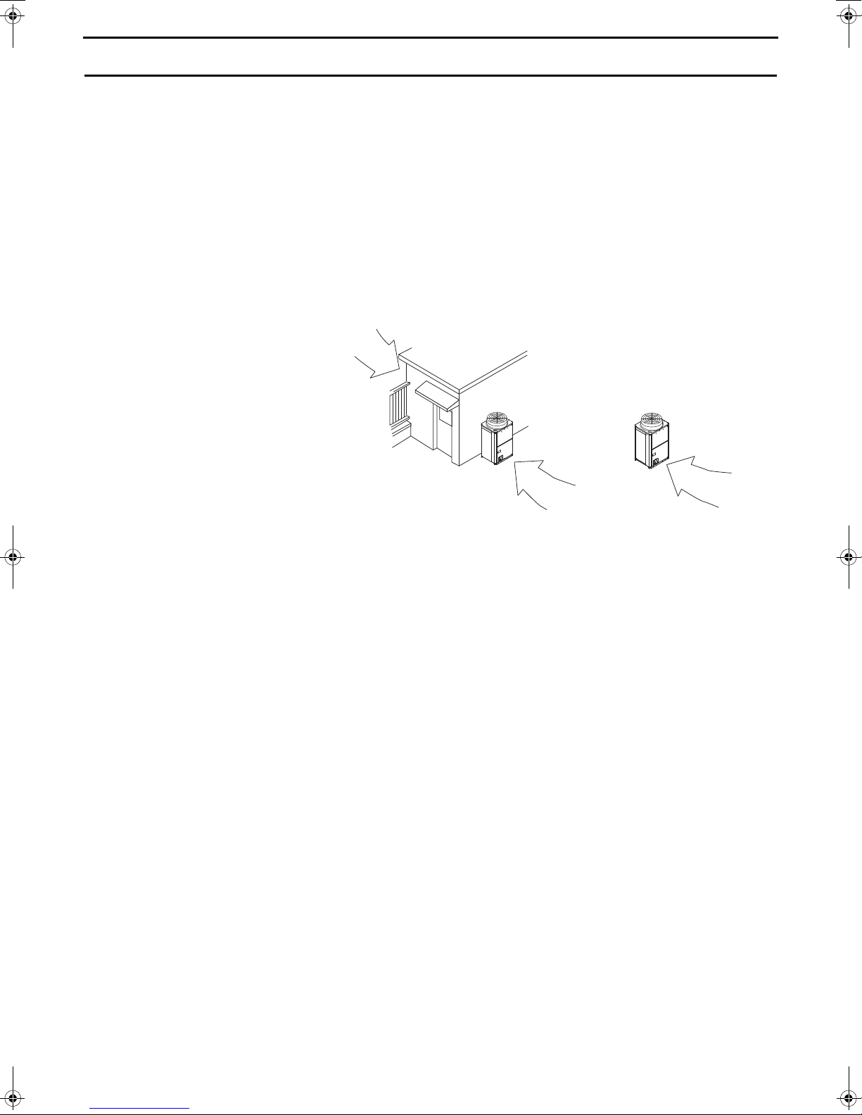
1. Selecting the Installation Site
Wind
Wind
Wind
• Install the outdoor unit in a place
where it is not exposed to direct wind,
such as behind a building.
• Install the outdoor
unit so that the outlet/
inlet faces away from
the wind.
[1] Installation Conditions
Select the installation site in consultation with the client.
Select a site to install the outdoor unit that meets the following conditions:
• This unit is for outdoor installation only.
• The unit will not be subject to heat from other heat sources.
• The noise from the unit will not be a problem.
• The unit will not be exposed to strong winds.
• Water from the unit can be drained properly.
• The space requirements (specified on pages 7 through 9) are met.
<1> Providing protection against winds
Using the figures at right as a reference,
provide adequate protection against
winds.
A unit installed alone is vulnerable to
strong winds. Select the installation site
carefully to minimize the effect of winds.
When installing a unit in a place where
the wind always blows from the same
direction, install the unit so that the outlet
faces away from the direction of the
wind.
<2> Cold Climate Installation
Observe the following when installing the units in areas where snow or strong winds prevail.
• Avoid direct exposure to rain, winds, and snow.
• Icicles that may form under the foundation can fall and inflict personal injury or property damage. Select the
installation site carefully to reduce these risks, especially when installing the unit on a roof.
• If the units are installed in the direct line of rain, winds, or snow, install the optional snow hood (on both the
discharge and suction ducts). Use a snow net or snow fence as necessary to protect the unit.
• Install the unit on a base approximately twice as high as the expected snowfall.
• If the unit is continuously operated for a long time with the outside air temperature below the freezing point, install
a heater at the base of the unit to prevent the water from freezing at the unit bottom.
• When using the unit in an outdoor temperature of -15
capacity is 320 W or more) at the bottom surface of the unit.
ºC or below, install a drain pan (with heater whose
6
Page 7

[2] Installation Space Requirements
L1
L2
L3
L3
* Height limit
Front/Right/Left Same height or lower than the overall height of the unit
Rear 500 mm or lower from the unit bottom
Unit height
Unit height
500
[mm]
When the wall(s) at the front and/or
the right/left exceed(s) their height
limits
h3
L1
L2
L3
L3
h1
Unit height
Unit height
500
When the wall at the rear exceeds
its height limit
h3
L1
L2
L3
L3
h1
L1
L2
L3
L3
h2
500
Unit height
Unit height
When all walls exceed their height
limits
L1
h3
h2
L2
L3
L3
h1
500
Unit height
Unit height
Provide sufficient space around the unit for effective operation, efficient air movement, and ease of access for
maintenance.
<1> Single unit installation
(1) When all walls are within their height limits*.
Required minimum distance [mm]
L1 (Front) L2 (Rear) L3 (Right/Left)
When the distance behind the unit (L2) needs to be small 500 300 50
(2) When one or more walls exceed their height limits*.
Add the dimension that exceeds the height limit (shown as "h1" through "h3" in the figures) to L1, L2, and L3 as
shown in the table below.
When the distance behind the unit (L2) needs to be small 500 + h1 300 + h2 50 + h3
Required minimum distance [mm]
L1 (Front) L2 (Rear) L3 (Right/Left)
7
Page 8
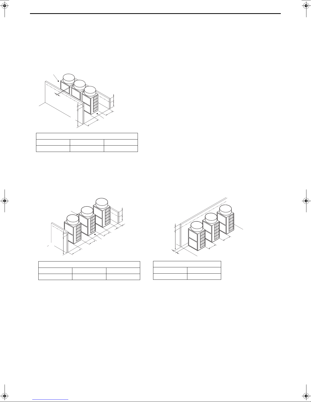
<2> Multiple unit installation
h2
L2
L1
h1
L4
Ⓐ
Ⓐ
[mm]
Unit height
500
Required minimum distance [mm]
L1 (Front) L2 (Rear) L4 (Between)
500 + h1 300 + h2 100
Ⓐ Leave open in two directions.
When there are walls in the front and rear of
the block of units
h1
h2
L1
L4
L4
L2
Ⓐ
Ⓐ
500
Unit height
Required minimum distance [mm]
L1 (Front) L2 (Rear) L4 (Between)
500 300 500
Ⓐ Leave open in two directions.
When there is a wall on either the right or left
side of the block of units
h3
L4
L3
L4
Unit height
Required minimum distance [mm]
L3 (Right/Left) L4 (Between)
50 + h3 500
When installing multiple units, make sure to take into consideration factors such as providing enough space for
people to pass through, ample space between blocks of units, and sufficient space for airflow. (The areas marked
with Ⓐ in the figures below must be left open.)
In the same way as with the single unit installation, add the dimension that exceeds the height limit (shown as "h1"
through "h3" in the figures) to L1, L2, and L3 as shown in the tables below.
(1) Side-by-side installation
(2) Face-to-face installation
8
Page 9
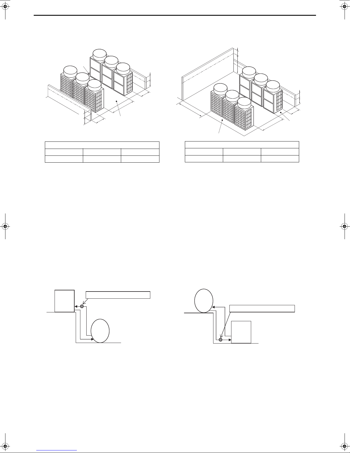
(3) Combination of face-to-face and side-by-side installations
When there are walls in the front and rear of
the block of units
h2
h2’
L2’
L4
L2
Ⓐ
Ⓐ
500
500
Required minimum distance [mm]
L2 (Right) L2’ (Left) L4 (Between)
300 + h2 300 + h2’ 1000
Ⓐ Leave open in two directions.
When there are two walls in an L-shape
h2
h3
L2
L4
L3
Ⓐ
Ⓐ
Unit height
500
Required minimum distance [mm]
L2 (Right) L3 (Right/Left) L4 (Between)
300 + h2 1000 + h3 1000
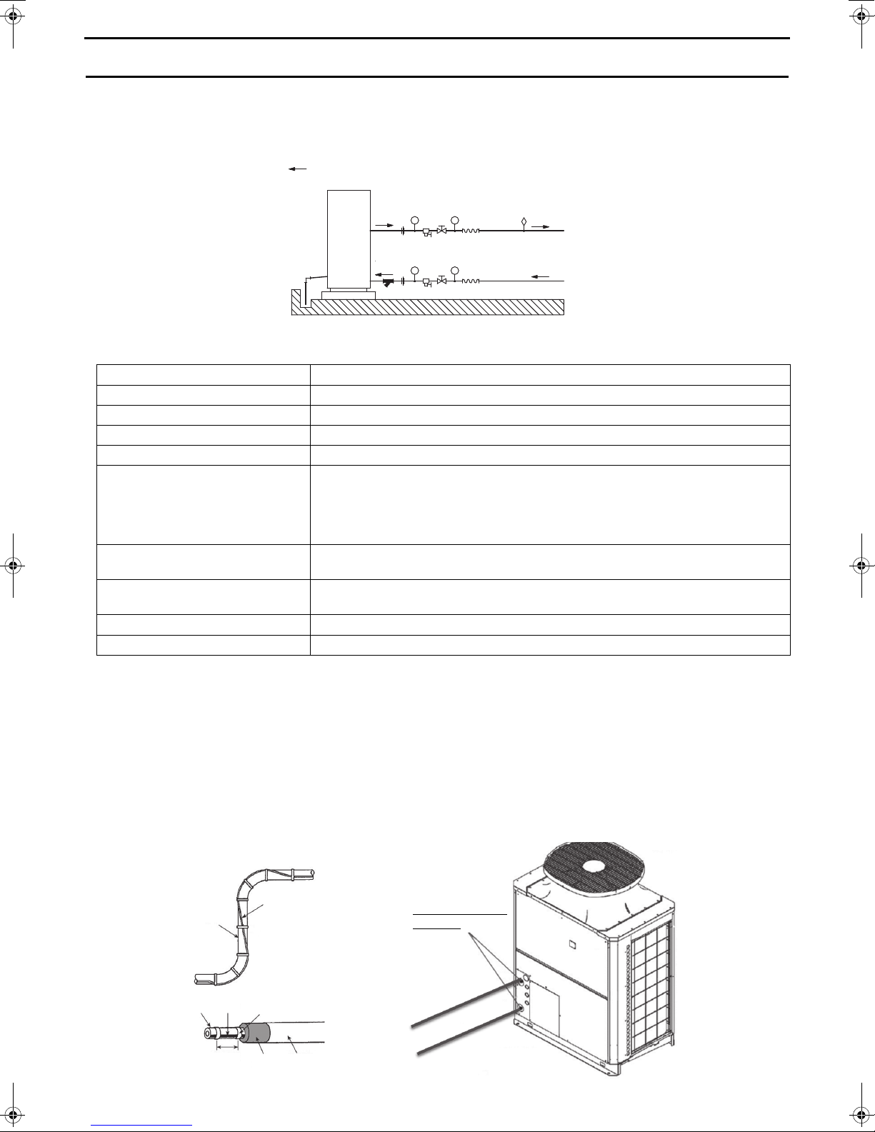
• When the unit is installed above the storage
tank
Decide the height so that the unit inlet water
pressure will not be negative for the tank
pressure.
Unit inlet water pressure > 0 MPa
Storage
tank
Heat
pump
unit
• When the unit is installed below the storage
tank
Decide the height so that the unit inlet water
pressure will be 0.5 MPa or below for the tank
pressure.
Heat
pump
unit
Storage
tank
Unit inlet water pressure < 0.5 MPa
[3] System installation restrictions
• Piping length restrictions
The maximum piping length is 60 m.
Select appropriate diameter pipes to prevent negative pressure from the pumping head and the pressure loss in the
pipes.
Pumping head (when maximum flow rate is 17
• Installation height restrictions
/min): 70 kPa
9
Page 10
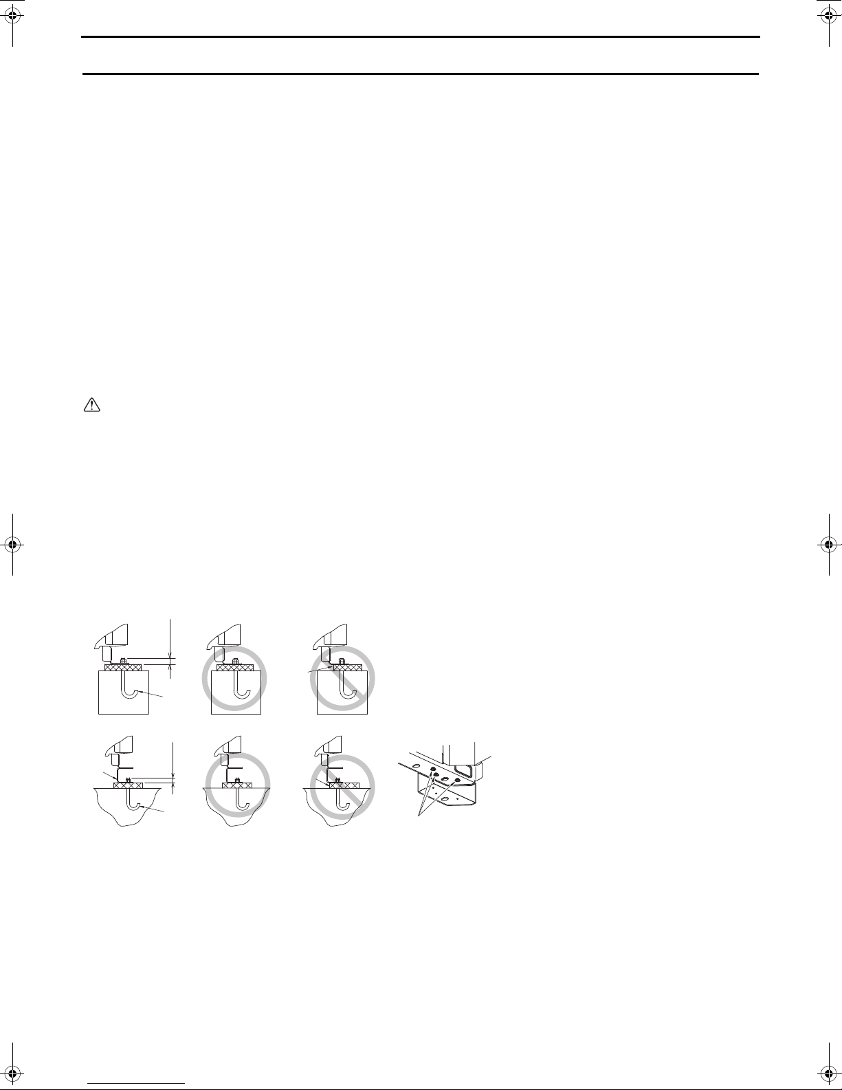
2. Unit Installation
A: M10 anchor bolt (field supply)
B: Corner is not seated.
C: Detachable leg
D: Screws
30 mm
A
30 mm
A
B
B
D
C
Units should be installed only by personnel certified by Mitsubishi Electric.
• Securely fix the unit with bolts to keep the unit from falling down during earthquakes or due to strong winds.
• Install the unit on a foundation made of concrete or iron.
• Noise and vibrations from the unit may be transmitted through the floor and walls. Provide adequate protection
against noise and vibration.
• Build the foundation in such way that the corners of the installation legs are securely supported as shown in the
figure below. When using rubber vibration isolators, make sure they are large enough to cover the entire width of
the unit's legs. If the corners of the legs are not firmly seated, the legs may bend.
• The projecting length of the anchor bolt should be less than 30 mm.
• This unit is not designed to be installed using hole-in anchor bolts unless brackets are used to support the four
corners of the unit.
• The legs on the unit are detachable.
• Detaching the legs
Loosen the three screws on the legs to detach each leg (two each in the front and back). If the finish coat becomes
damaged when detaching the legs, be sure to touch it up.
Warning:
• Be sure to install the unit on a surface strong enough to withstand its weight to keep the unit from falling
down and causing injury.
• Provide adequate protection against strong winds and earthquakes. Improper installation may cause the
unit to fall down, resulting in personal injury.
When building the foundation, take the floor strength, water drainage during operation, and piping and wiring routes
into consideration.
Precautions for routing the pipes and wires underneath the unit without detachable legs
When routing the pipes and wires underneath the unit, make sure that the foundation will not block the piping access
holes. Also, make sure the foundation is at least 100 mm high so that the piping can pass under the unit.
10
Page 11
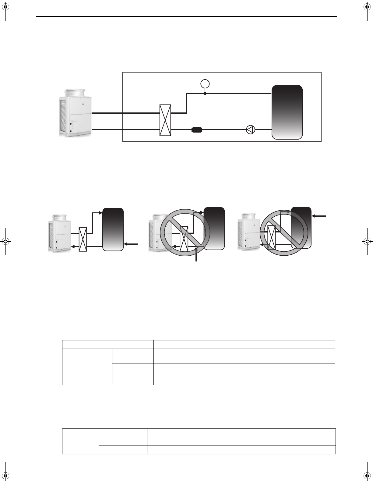
3. Water Pipe Installation
indicates the direction of the water flow.
Heat pump unit
To storage tank
Water piping diagram
From storage tank
Heater
Piping
Joint section 0ºC
or higher
Tape
Heater
Piping
250 mm
Heat insulator
[1] Schematic Piping Diagram and Piping System Components
③
①
②
④
PT
⑤
⑧
⑨
②
⑩
④
③
PT
⑤
⑥
⑦
①
1 Union joints/flange joints Required to allow for a replacement of equipment.
2 Thermometer Required to check the performance and monitor the operation of the units.
3 Water pressure gauge Recommended for checking the operation status.
4 Valve Required to allow for a replacement or cleaning of the flow adjuster.
5 Flexible joint Recommended to prevent the noise and vibration from the pump from being transmitted.
Install the drain pipe with a downward inclination of between 1/100 and 1/200. To
prevent drain water from freezing in winter, install the drain pipe as steep an angle as
6 Drain pipe
practically possible and minimize the straight line.
For cold climate installation, take an appropriate measure (e.g., drain heater) to prevent
the drain water from freezing.
7 Strainer
8 Air vent valve
Install a strainer near the unit to keep foreign materials from entering the water-side
head exchanger (supplied).
Install air venting valves to the places where air can accumulate.
Automatic air vent valves are effective.
9 Water pipe Use pipes that allow for easy air purging, and provide adequate insulation.
0 Drain valve Install drain valves so that water can be drained for servicing.
* Installing a freezing prevention heater
1 In cold areas (where the outside temperature drops below freezing), provide a freezing prevention heater at all
local pipes to prevent spontaneous freezing.
2 After the heater is installed, check outside temperature +25ºC is ensured at the heat pump unit inlet/outlet pipe
joint section (at outside temperature -25ºC, joint section 0ºC or higher).
3 Depending on the local piping material, prevent overheating by selecting a self temperature adjustment type
heater or other method.
Heater installation example
11
Page 12
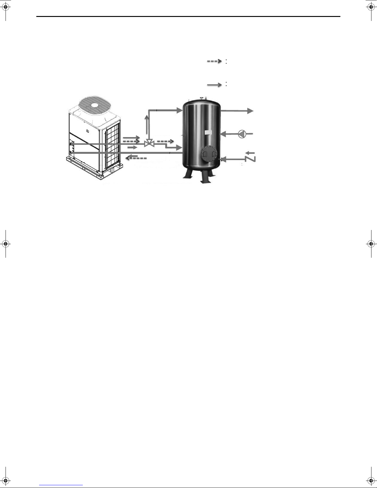
* 3-way valve installation
Hot water storage operation
Anti-freezing operation
Residual running of the pump
* The ON/OFF control of 3-way valve
depends on the output type “(r) EXTERNAL
DEVICE” on page 58.
Please connect 3-way valve on the lower part of the storage tank except when the unit is in operation. Antifreezing operation will keep the water in the tank circulated and water storage tanks can become thermally
stratified.
12
Page 13
[2] Notes on Pipe Corrosion
Water treatment and water quality control
Poor-quality circulating water can cause the water-side heat exchanger to scale up or corrode, reducing heatexchange performance. Properly control the quality of the circulating water.
• Removing foreign objects and impurities in the pipes
During installation, keep foreign objects, such as welding and sealant fragments and rust, out of the pipes.
• Water Quality Control
(1) Poor-quality water can corrode or scale up the heat exchanger. Regular water treatment is recommended.
Water circulation systems using open heat storage tanks are particularly prone to corrosion.
When using an open heat storage tank, install a water-to-water heat exchanger, and use a closed-loop circuit
on the air-conditioner side. If a water supply tank is installed, keep contact with air to a minimum, and keep the
level of dissolved oxygen in the water no higher than 1 mg/.
(2) Water quality standard
Higher mid-range temperature water system
Items
pH (25˚C) 6.5 ~ 8.0 6.5 ~ 8.0
Electric conductivity (mS/m) (25˚C) 30 or less 30 or less
(µs/cm) (25˚C) [300 or less] [300 or less]
Chloride ion
Standard
items
Reference
items
Reference: Guideline of Water Quality for Refrigeration and Air Conditioning Equipment. (JRA GL02E-1994)
Sulfate ion
Acid consumption
(pH4.8) (mg CaCO
Calcium hardness
Ionic silica
Iron (mg Fe/) 0.3 or less 0.3 or less
Copper (mg Cu/) 0.1 or less 0.1 or less
Sulfide ion
Ammonium ion
Residual chlorine (mg Cl/ ) 0.1 or less 0.1 or less
Free carbon dioxide
(mg CaCO
(mg Cl
(mg SO4
(mg SiO
(mg S2-/)
(mg NH
(mg CO
-
/)
2-
/)
/)
3
/)
3
/)
2
+
/)
4
/)
2
Water Temp. > 60ºC
Recirculating water Recirculating water Corrosive
30 or less 30 or less
30 or less 30 or less
50 or less 50 or less
6.5 pH 7.5 : 90 or less
7.5 pH 8.0 : 50 or less
30 or less 30 or less
Not to be detected Not to be detected
0.1 or less 0.1 or less
10.0 or less 10.0 or less
Make-up water criteria
(with secondary side control enabled)
Water Temp. > 60ºC
250 or less
Tendency
Scale-
forming
(3) Please consult with a water quality control specialist about water quality control methods and water quality
calculations before using anti-corrosive solutions for water quality management.
(4) When replacing an air conditioner (including when only the heat exchanger is replaced), first analyze the water
quality and check for possible corrosion.
Corrosion can occur in water systems in which there has been no signs of corrosion. If the water quality level
has dropped, adjust the water quality before replacing the unit.
(5) Suspended solids in the water
Sand, pebbles, suspended solids, and corrosion products in water can damage the heating surface of the heat
exchanger and cause corrosion. Install a good quality strainer (60 mesh or better) at the inlet of the unit to filter
out suspended solids.
(6) Connecting pipes made from different materials
If different types of metals are placed in direct contact with each other, the contact surface will corrode.
Install an insulating material between pipes that are made of different materials to keep them out of direct
contact with each other.
13
Page 14
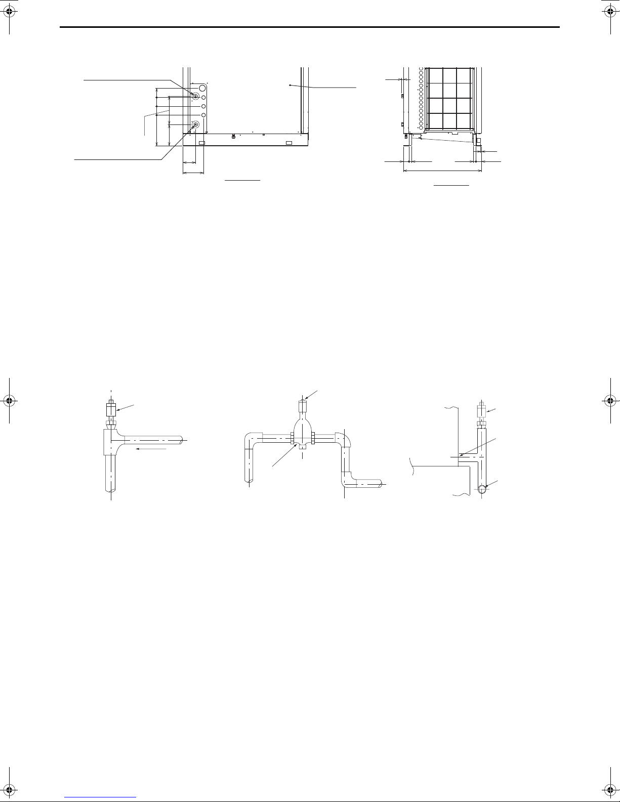
[3] Water Pipe Hole Size and Location
Water inlet
(Bronze Rc3/4, female screw)
Service panel
Front view
Side view
Hot water outlet
(Bronze Rc3/4, female screw)
Automatic air venting valve
Automatic air venting valve
Air venting valve installation example
Air separator
Automatic air
venting valve
Hot water outlet
Crosscut pipe
Base
Heat pump unit
Upward gradient 1/200
19
85 9085
274
297
206
122
199
26 5454 26
755
9
[4] Pipe gradient and air venting valve (Outlet hot water pipe)
During the hot water storage operation, the air dissolved in the water is discharged in the form of bubbling from the
outlet hot water pipe to quickly raise low-temperature water to the required temperature. When the air accumulates in
the pipe, the resistance of the water circuit will increase and the flow rate will extremely decrease. Because of this, an
installation of automatic air venting valves is required when there is a pipe that slopes down in the outlet hot water
pipe.
Install the pipe with an upward gradient of 1/200 or more toward the air vent to prevent air accumulation in the pipe.
Also, install air venting valves to the places where air can accumulate. The installation example is shown below.
Note:
• If the crosscut pipe is located lower than the hot water outlet of the heat pump unit, raise the pipe near the unit and
install an automatic air venting valve.
[5] Outlet check valve (When installing multiple units)
When connecting multiple units with pipes in parallel, install a check valve at the outlet pipe of each unit. If a check
valve is not installed, a circuit in which warm water flows back will be created in some units during the defrost cycle or
abnormal stop, and other units will come to an abnormal stop due to sudden change of the inlet water temperature.
14
Page 15
[6] Secondary side control system
T
I Unit heating circuit
II Secondary side circuit
III Hot water supply circuit
Temperature sensor
Flow sensor
䐣
䐤
䐣
䐤
䐟
T
䐠
䐥
䐬
䐦
䐨
䐩
䐧
䐪
䐡
䐢
䐫
䐭
䐥
䐬
䐦
P
䐪
䐩
P
From heat pump unit
To heat pump unit
From storage tank
To storage tank
When employing an indirect heat exchanger system using a separately sold Q-1SCK, be careful with regard to the
following points.
Install the Q-1SCK (flow sensor and temperature sensor) in the secondary side circuit as shown below to perform
control.
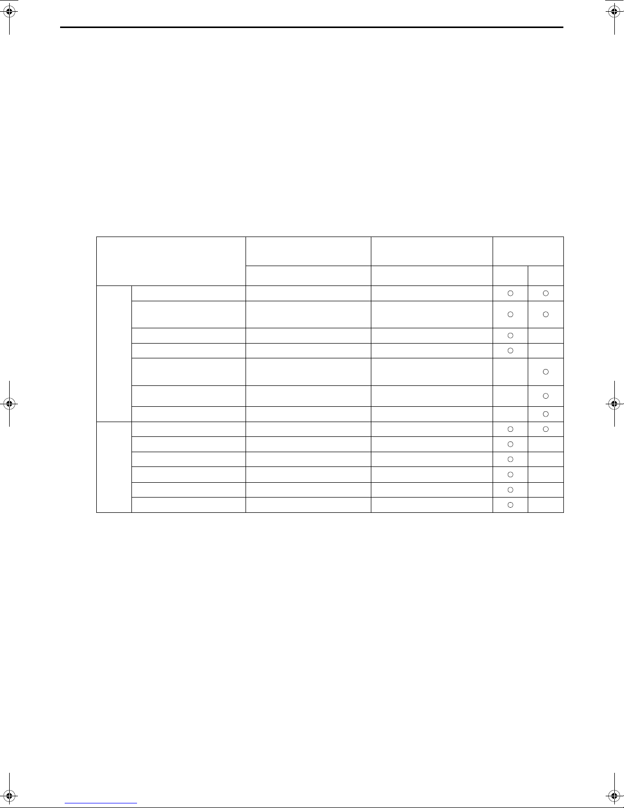
(1) Notes on configuring and selecting components
1 Points to note for secondary side water piping
I Details on components in the unit heating circuit
* For details, refer to page 11.
II Details on components in heat exchanger heating circuit
Schematic Piping Diagram and Piping System Components for secondary circuit
No. Component Application Remarks and notes on selecting and installing components
1
2
3
4
5 Water piping Water flow channel
6
7 Union joint
Flow sensor
(Optional parts)
Temperature
sensor
(Optional parts)
Plate heat
exchanger
Pump + Flow
rate adjustment
device
Anti-freeze
heater
Measures and controls
the secondary side flow
rate.
Measures and controls
the secondary side
outlet hot water
temperature.
Exchanges heat
between hot water
output from the unit and
water input from the
tank.
Outputs hot water from
the secondary side and
adjusts the flow rate.
Prevents pipe damage
due to freezing of the
water circuit.
Improves the workability
of replacing equipment.
P
Be sure to install this component between the downstream of the flow rate
adjustment device and the heat exchanger.
Install this component at the outlet of the heat exchanger.
Select a heat exchanger that is appropriate for the capacity.
Select a pump and flow rate adjustment device that are suitable for the system.
Install them at the lower outlet of the tank.
Be sure to perform insulation work.
Select pipes that allow for easy air bleeding.
This component needs to be installed in a location where an ambient
temperature may fall to 0˚C or less.
Install these components in the two places of the chilled water passage section
and the high temperature water passage section to enable replacement.
15
Page 16

No. Component Application Remarks and notes on selecting and installing components
Improves the workability
8 Val ve
9 Strainer
0 Air vent valve Bleeds air from the pipe. Install air vents in places where there is a risk of air accumulating.
a Flexible joint
Water pressure
b
gauge
c Expansion tank
d Drain valve
e Safety valve
of cleaning the heat
exchanger and
replacing parts.
Prevents foreign
materials from entering
into the heat exchanger.
Prevents the
propagation of vibration.
Used to check the
operation status.
Absorbs excessive
water pressure due to
expansion caused by a
rise in temperature.
Improves workability of
replacing equipment.
Prevents rupturing of
the water circuit.
Install these components in the two places of the chilled water passage section
and the high temperature water passage section to enable replacement.
Install a strainer with 60 mesh or better near the heat exchanger.
These components need to be installed in consideration of the pipe load as
pipes are easily damaged by bending.
Attach this component to each piping section to check the water pressure.
Select an expansion tank that is suitable for the system.
Install these components in the two places of the chilled water passage section
and the high temperature water passage section to enable replacement.
Be sure to provide an escape pipe to prevent discharged water from spraying on
passersby.
2 Selection criteria for heat exchanger
Step 1 Determination of prerequisites for selection
I Heat exchanger capacity 40000 W
II Estimation of outlet hot water and inlet water temperatures
As a guide, select a heat exchanger of which the temperature difference between the high temperature
section and the low temperature section will be 5˚C or below.
II-1 Outlet hot water temperature (when secondary side outlet hot water temperature is set to 65˚C (setting
at the time of shipment))
• Secondary side circuit outlet hot water temperature: 65˚C
• Unit outlet hot water temperature: 70˚C
II-2 Inlet water temperature
• Secondary side inlet water temperature: 10˚C
• Unit inlet water temperature: 15˚C
III Used flow rate
(40000 W/(70-15)˚C/4200 J/kg•K) × 60 s = 10.4 kg/min 10.4 /min
Step 2 Determination of model
Notes on selection
• Select a heat exchanger that allows water to pass through both of the flow channels.
• Select a heat exchanger so that the pressure applied to the heat exchanger in the on-site system will not
exceed the maximum operating pressure of the heat exchanger.
• Select a heat exchanger that allows flowing at a flow rate of maximum 30 /min.
• Select a heat exchanger with a capacity of at least 40000 W.
• Ensure that the shearing stress at the flow rate to be used will be 16 Pa or more. (Refer to step 4.)
* To increase the shearing stress:
• When the area per plate is equal, select a vertically long heat exchanger.
• Select a heat exchanger of which NTU is high (although the heat transfer capacity improves as NTU
increases, the pressure loss becomes high).
16
Page 17
Step 3 Determination of specifications of the heat exchanger
NTU1
T1
T
-----------=
NTU2
KA
VC
------------- -
=
Effective length
Representative length of 1 channel
Effective length:
Length between water inlet and water outlet
(refer to the figure on the right)
Representative length of 1 channel:
Distance between plates
(refer to the figure on the right)
× 2
P: Pressure loss
A shearing stress of 16 Pa or higher is required to reduce the amount of scale that adheres.
If the shearing stress is low:
• Select a vertically short shape.
• Change the shape of the plates.
Reselect a heat exchanger that will increase the shearing stress by following methods described above.
Distance between plates
Effective length
Side of heat exchanger
Front of heat exchanger
Determine the model of heat exchanger and number of plates in consultation with the heat exchanger
manufacturer based on the above requirements.
* To determine the number of plates, calculate the number of plates while referring to the example below.
Values to use when determining the number of plates:
1 Overall heat transfer coefficient of corresponding heat exchanger
2 Heat transfer area per plate
Calculation method
A Obtain the data of 1 and 2 from the heat exchanger manufacturer.
B Estimate the number of plates of the heat exchanger.
C Check that the number of transfer units for the corresponding number of plates matches between
NTU1 and NTU2 (NTU1=NTU2).
If they are matched, select a heat exchanger having the corresponding number of plates. If they are
not matched, change the number of plates and then return to B to perform the calculation again.
T1: Temperature difference between inlet and
outlet
T: Temperature difference of high temperature
part (low temperature part)
K: Overall heat transfer coefficient (W/m
2
K)
A: Total heat transfer area (m
G: Total mass flow rate (kg/s)
C: Specific heat (J/kgK)
Step 4 Calculation of the shearing stress
Calculate the shearing stress using the following method.
Values required for calculation
• Relationship between flow rate and pressure loss of corresponding heat exchanger (Obtain the data
from the heat exchanger manufacturer.)
2
)
Calculation method
Calculate the shearing stress using the following formula.
17
Page 18
3 Configuration method and selection criteria of flow rate adjustment device
Overview of system
This system has a pump provided at the outlet
of the tank and a three-way valve provided
downstream of the pump, and adjusts the flow
rate by controlling the opening and closing of
the three-way valve.
Flow rate
output device
Flow rate
adjustment
device
Pump
Three-way
valve
Wiring
connection
places
1-3 of CN512 of
control board
(ON/OFF output)
Sub box
terminal block
No. 10, 11, 12
ON/OFF signal
0 to 10 V output
Three-way
valve
Pump
In this system, a flow rate adjustment device is installed in the secondary side circuit to perform secondary side
flow rate adjustment control by outputting 0 to 10 V from the unit.
* 10-V power supply is not supplied.
The following shows a system configuration example of the flow rate adjustment device and notes on the
system configuration.
The following three system types are recommended as flow rate adjustment devices:
1. System using a three-way valve
2. System using a two-way valve
3. System using an inverter
1. System using a three-way valve
Notes on selection method and system configuration
Notes on pump selection and connection
• Calculate the total pump head according to the system at the site and then select a pump capable of outputting
the minimum flow rate of about 3 /min and maximum flow rate of about 30 /min with the necessary pump head
for the piping at the site.
• When selecting the pump, please note that output at a high flow rate will not occur if the flow rate with the pump
head of the system at the site is low, and output at a low flow rate will not occur if the flow rate is too high.
• Be sure to check that the flow rate becomes 20 to 30 /min at the maximum output during a flow rate adjustment
test run (refer to page 37).
For how to check the flow rate, refer to page 38.
* If the flow rate is not within the range of 20 to 30 /min, select a different pump or adjust the maximum frequency
using an inverter, etc. so that the maximum flow rate of 20 to 30 /min is achieved.
* To select a proper pump, first select a pump that supports slightly high flow rate, and then adjust the frequency
with an inverter so that the flow rate becomes 20 to 30 /min at the maximum output.
(In that case, an inverter is necessary to be prepared separately.)
Notes on three-way valve selection and connection
• Use a valve that is capable of adjusting the flow rate with a 0 to 10 V input.
• Calculate the Cv value and select a valve that supports an appropriate rate.
• Select a valve of which the ratio of the maximum flow rate and the minimum flow rate will be at least 1:10.
• Place the three-way valve downstream of the pump. Connect one outlet to the heat exchanger.
Connect the other outlet to the lower part of the tank.
• Carefully read the instruction manual and use the three-way valve in accordance with the usage procedures.
18
Page 19
2. System using a two-way valve
Overview of system
This system has a pump provided at the outlet of the
tank and a two-way valve provided downstream of
the pump, and adjusts the flow rate by controlling the
opening and closing of the two-way valve.
Flow rate
output device
Flow rate
adjustment device
Pump Two-way valve
Wiring
connection
places
1-3 of CN512 of
control board
(ON/OFF output)
Sub box
terminal block
No. 10, 11, 12
ON/OFF signal
0 to 10 V output
Two-way
valve
Pump
Overview of system
This system has a pump provided at the outlet
of the tank and an inverter connected to the
pump, and adjusts the flow rate by changing
the frequency of the inverter.
Flow rate
output
device
Flow rate
adjustment
device
Pump Inverter
Wiring
connection
places
-
Sub box
terminal block
No. 10, 11, 12
0 to 10 V output
Pump
Inverter
Notes on pump selection and connection
Select a pump in the same way as for a system with a three-way valve.
Notes on two-way valve selection and connection
• Use a valve that is capable of adjusting the flow rate with a 0 to 10 V input.
• Calculate the Cv value and select a valve that supports an appropriate rate.
• Select a valve of which the ratio of the maximum flow rate and the minimum flow rate will be at least 1:10.
• There are various kinds of two-way valve (such as ball valve, butterfly valve, and globe valve), and there are
valves suitable for flow rate adjustment and valves that are not suitable for flow rate adjustment. Therefore be
sure to select a two-way valve of a kind capable of precisely controlling the flow rate, such as a butterfly valve or
globe valve.
• Place the two-way valve downstream of the pump.
• Carefully read the instruction manual and use the two-way valve in accordance with the usage procedures.
3. System using an inverter
Notes on pump selection and connection
Select a pump in basically the same way as for a system with a three-way valve or two-way valve.
• Select a pump that can be used also at a low frequency (6 Hz or less).
(The motor may be seized depending on the pump selected as this control is performed at a low frequency.)
• Select a pump of which flow rate at 100% output is between 20 to 30 /min.
Notes on inverter selection and connection
• The inverter needs to be able to adjust output with a 0 to 10 input.
• Select an inverter that will not cause the seizing of the motor.
• Configure the settings so that the flow rate on the secondary side will become 0 /min when the unit is not
operating.
• Carefully read the instruction manual and use the inverter in accordance with the usage procedures.
19
Page 20
(2) Notes on other piping work
T
QAHV-N560YA-HPB
Installation indoors
Secondary side
heat exchanger
Secondary side thermistor
Secondary side flow sensor
Storage tank
Installation outdoors
Secondary side pump
QAHV-N560YA-HPB QAHV-N560YA-HPB QAHV-N560YA-HPB
Storage tank
Water
supply
Storage tank
Storage tank
Water supply
Water
supply
1 Notes on installation location of secondary side circuit
Install the secondary side heat exchanger, secondary side thermistor, secondary side flow sensor, and secondary
side pump indoors as shown in the figure for the secondary side circuit system. Also, take measures so that the
piping will not freeze.
2 Notes on hot water supply piping
Be sure to connect the hot water supply piping to the lower part of the storage tank. If you connect it to the unit
inlet pipe, an abnormal stop (high pressure or gas cooler outlet temperature) may occur or the outlet hot water
temperature may decrease due to the sudden change of the inlet water temperature (5 K/min or more
instantaneously or 1 K/min or more consecutively) during operation.
3 About anti-freezing operation
This unit performs anti-freezing operation. Furthermore, the control method can be changed according to the
system at the site. The following two items can be changed.
1. Prevent disturbance of thermal stratification in the tank
To prevent the disturbance of the thermal stratification in the tank while the indoor temperature is sufficiently high,
set the item code 1514 to "1" so that the judgment criterion for starting the anti-freezing operation of the
secondary side circuit matches with the secondary side circuit water temperature criterion.
Setting procedure and operation overview
Setting procedure Operation
0 (Initial setting)
Item code 1514
1
Performs anti-freezing operation in the secondary side circuit when the water
temperature in the unit side circuit becomes the standard value or below.
Performs
anti-freezing operation
in the secondary side circuit when the water
temperature in the secondary side circuit becomes the standard value or
below.
2. Purpose and application: Prevent piping freezing when the secondary side control is used
a risk of the piping of the primary side freezing, so set SW2-5 to "ON" so that the compressor runs during the
anti-freezing operation.
Setting procedure and operation overview
Setting procedure Operation
SW2-5
OFF (Initial setting) The compressor does not operate when the anti-freezing operation is performed.
ON The compressor operates when the anti-freezing operation is performed.
If the compressor is not run during the anti-freezing operation in the secondary side control system, there is
20
Page 21
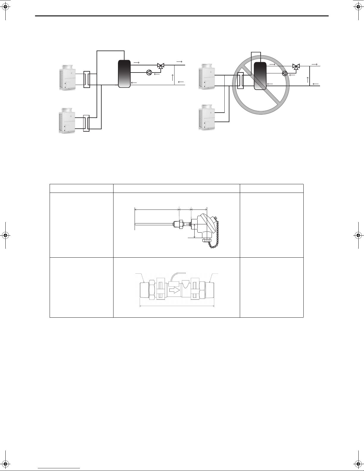
4 When connecting multiple units
QAHVN560YA-HPB
QAHVN560YA-HPB
QAHVN560YA-HPB
QAHVN560YA-HPB
Storage tank
Storage tank
ABC
D
A
BC
To connect multiple units, configure one secondary side circuit system for each unit as shown in the figure
below. (Install a heat exchanger, flow sensor, and thermistor for each unit.)
(3) Optional parts
The flow sensor and thermistor in the system are sold separately.
For the pipe connection method, refer to the manuals of the optional parts (Q-1SCK).
Secondary circuit kit Q-1SCK The size and length noted are approximate.
Parts Shape Specification
(4) Setting method for secondary side control
A: 157 mm
Thermistor
B: 42 mm
C: 54 mm
D: 48 mm
A: 129 mm
Flow sensor
B: R3/4
C: R3/4
Wiring length: 1.9 m
After configuring the secondary side control system, perform the following operation to perform the secondary side
control operation.
1. Set the digital setting item "121" to 1 (for details on the operating procedure, refer to page 28).
2. Perform a water flow rate adjustment operation (for details, refer to “Water flow rate adjustment operation (when
the secondary side control is enabled)” (page 37)).
21
Page 22
4. System Configurations
Unit (MAIN circuit)
PCB
External
temperature
sensor
Field-supplied dry contact
switch/relay or remote
controller (PAR-W31MAA) or
centralized controller (AE-200)
Field-supplied dry contact
switch/relay or remote
controller (PAR-W31MAA) or
centralized controller (AE-200)
External
temperature
sensor
Unit (MAIN circuit)
PCB
* Each unit is operated individually by connecting a dry contact switch/relay to each unit.
External
temperature
sensor
Field-supplied dry contact
switch/relay or remote
controller (PAR-W31MAA) or
centralized controller (AE-200)
MAIN
unit
SUB unit
SUB unit(s)
n units
Inter-unit wiring
(M-NET line)
Inter-unit wiring
(M-NET line)
Unit (MAIN circuit)
PCB
Unit (MAIN circuit)
PCB
Unit (MAIN circuit)
PCB
* A group of unit that consists of one main unit and up to 15 sub units is operated collectively by connecting an external water temperature sensor and a dry
contact switch/relay to the main unit.
Test run procedural flow
1.System startup (*)
Configure the settings needed for the local system.
Refer to page 23 for details.
2.Air bleeding operation
Operate the unit’s pump to perform the air bleeding operation.
Refer to page 33 for details.
3. Water flow rate adjustment operation
Adjust the unit’s pump and flow rate adjustment valve.
Refer to pages 35 and 37 for details.
* If multiple units are connected to the same water circuit, perform the water flow rate adjustment operation for each unit simultaneously.
(*)
Request at the Time of a Test Run
Set the slide switch SWS2 on the board inside the control box to the “lower side”
By default, it is set to the “upper side” for forced stop of the pump and compressor to prevent the pump being
damaged by the anti-freezing process in no water passing status or valve closed status before the test run.
during the test run.
[1] Schematic Diagrams of Individual and Multiple Systems
(1) Individual system
Refer to the sections “[2] Switch Types and the Factory Settings” (page 23) and
“(3) System configuration procedures: Individual system” (page 27) for further details.
(2) Multiple system (2-16 units)
Refer to the sections “[2] Switch Types and the Factory Settings” (page 23) and
“(4) System configuration procedures : Multiple system” (page 29) for further details.
22
Page 23
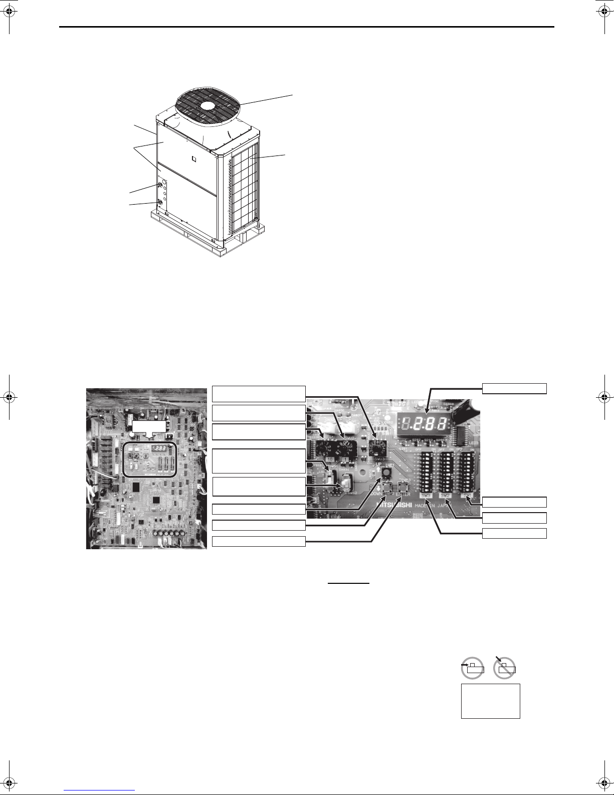
[2] Switch Types and the Factory Settings
Discharge air outlet
Service panel
Control box
Intake air inlet
Rotary switch (SWU3) (0-F)
Rotary switch (SWU2) (0-9)
Rotary switch (SWU1) (0-9)
Slide switch (SWS1)
(LOCAL, OFF, and REMOTE
from the top)
Push switch (SWP1) "UP"
Push switch (SWP2) "DOWN"
Push switch (SWP3) "ENTER"
Slide switch (SWS2) *
(A and B from the top)
Switches
[Entire view of a PCB] [Enlarged view of the switches]
LED display
Dip switch (SW1)
Dip switch (SW2)
Dip switch (SW3)
Slide the dip
switches; do not
push down the
switches.
(1) Switch names and functions
Wate r outl et
Water inlet
There are four main ways to set the settings as follows:
1Dip switches (SW1 - SW3)
2Dip switches used in combination with the push switches
3Rotary switches
4Slide switches
See below for how these switches are used to set certain items.
Different types of switches on the PCB
Set the slide switch SWS2 on the board inside the control box to the lower side during the trial run.
By default, it is set to the upper side for forced stop of the pump and compressor to prevent the pump
being damaged by the anti-freezing process in no water passing status or valve closed status before
the test run.
Upper side: A (under preparation)
Lower side: B (auto)
Always set to the lower side.
* Setting to the upper side forcefully stops the pump and compressor thus the unit does not
operate.
* When SWS2 is set to the upper side, the display shows “P.OFF” and the setting cannot be
made. When “P.OFF” appears, set SWS2 to the lower side.
23
Page 24
(2) Factory Switch Settings (Dip switch settings table)
Factory setting
SW Function Usage MAIN circuit OFF setting ON setting
1
2
3
Model setting
4
5
SW1
6 Test run 1 OFF - Operation during test run Any time
7 Not used OFF Leave the setting as it is. At a reset
8 Test run 2 OFF - Operation during test run
9 Test run 3 OFF - Operation during test run
10 Model setting ON Leave the setting as it is. At a reset
1 Model setting OFF Leave the setting as it is. At a reset
2 Model setting OFF Leave the setting as it is. At a reset
3 Model setting OFF Leave the setting as it is. At a reset
4 Model setting OFF Leave the setting as it is. At a reset
5 Freeze-up protection method switching OFF
Power supply option to the
6
SW2
SW3
"-" in the table indicates that the function in the corresponding row will be disabled regardless of the actual switch setting.
The factory setting for these items is OFF.
Refer to page 32 for how to reset errors.
communication circuit
7 Model setting OFF Leave the setting as it is. At a reset
8 Model setting OFF Leave the setting as it is. At a reset
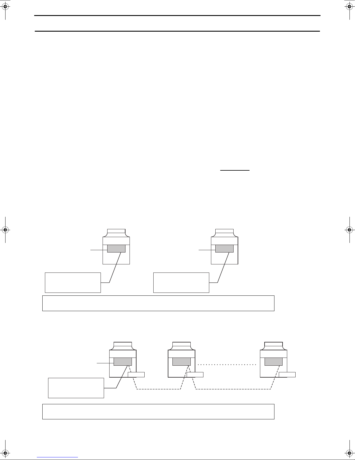
1Individual/Multiple system
9
2AE connection
10 Display mode switch 7
1 Remote reset
Auto restart after power
2
failure
3 Test run 4 OFF - Operating during test run Any time
4 Function switching (Do not change this setting.) OFF Leave the setting as it is. At a reset
5 Display mode switch 1
6 Display mode switch 2 OFF Changes the 7-segment LED display mode. Any time
7 Display mode switch 3 OFF Changes the 7-segment LED display mode. Any time
8 Display mode switch 4 OFF Changes the 7-segment LED display mode. Any time
9 Display mode switch 5 OFF Changes the 7-segment LED display mode. Any time
10 Display mode switch 6 OFF Changes the 7-segment LED display mode. Any time
Switches between supplying or not
supplying power to the communication
circuit.
1Selects between individual and Multiple
system
2Selects AE connection or not
This switch is used in combination with dip
switches SW3-5 through 3-10 and push
switches SWP 1, 2, and 3 to configure or
view the settings when performing a test
run or changing the system configuration.
Enables or disables the error to be reset
from a remote location.
Enables or disables the automatic
restoration of operation after power failure
(in the same mode as the unit was in
before a power failure).
These switches are used in combination
with dip switches SW2-5 and push
switches SWP 1, 2, and 3 to configure or
view the settings when performing a test
run or changing the system configuration.
Depends on
the unit
ON
OFF Individual system
OFF Changes the 7-segment LED display mode. Any time
ON
ON
OFF Changes the 7-segment LED display mode. Any time
Leave the setting as it is. At a reset
Pump operation +
heater energization
Does not supply power to
the communication circuit.
Disables the error to be
reset from a remote
location.
An alarm will be issued
when power is restored
after a power outage.
The alarm will be reset
when the power is turned off
and then turned back on.
Compressor operation +
heater energization
Supplies power to the
communication circuit.
Multiple system or during
AE connection
Enables the error to be
reset from a remote
location.
Automatically restores
operation after power
failure.
Setting
timing
Any time
At a reset
Any time
At a reset
At a reset
Any time
24
Page 25
[3] Configuring the Settings
The settings must be set only by a qualified personnel.
<1> Making the settings
Use the LED display and the three push switches (SWP1 (), SWP2 (), and SWP3 (Enter)) to change the current
settings on the circuit board and to monitor various monitored values.
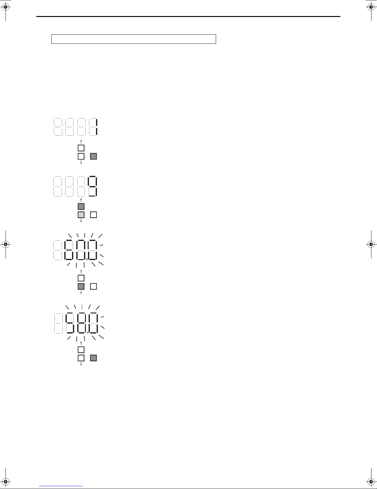
(1) Setting procedures
Take the following steps to set the push switches SWP1 through SWP3. These switches must be set after the dip
switches SW2 and SW3 have been set.
1 Normally an item code appears on the display.
(The figure at left shows the case where item code 1 is displayed.) Press SWP3
(Enter) to advance the item code.
SWP1
SWP2
SWP3
Enter
2 The left figure shows a display example (Code 9 Outlet hot water temperature
SWP1
SWP2
SWP3
Enter
Press SWP3 (Enter) until the item code appears that corresponds to the item to change or
monitor its value.
setting).
Press either SWP1 () or SWP2 () to display the value that corresponds to the
selected item.
3 The current setting value will blink.
The left figure shows that the current setting value is "60.0."
To decrease this value to 58.0, for example, press SWP2 ().
Press SWP1 () to increase the value.
SWP1
SWP2
SWP3
Enter
4 <To change the settings>
When the desired value is displayed (58.0 in the example at left), press SWP3 (Enter).
The displayed value will stop blinking and stay lit.
A lit LED indicates that the new setting has been saved.
SWP1
SWP2
SWP3
Enter
* Pressing SWP1 () or SWP2 () will change the blinking setting value, but the
change will not be saved until SWP3 (Enter) is pressed.
If SWP3 is not pressed within one minute, the change will not be saved and the
display will return to the item code display mode.
Press and hold SWP1 () or SWP2 () for one second or longer to fast forward
through the numbers.
<To view the monitored data>
Press SWP3 (Enter) while the LED display is blinking (see step 3 above) to stop the
blinking.
* The values of the items that can only be monitored will not change when SWP1 ()
or SWP2 () is pressed.
The display will stop blinking and stay lit after a minute, and the display will
automatically return to the item code display regardless of the type of values
displayed.
To change the values of other items, repeat the steps from step 2 above.
25
Page 26
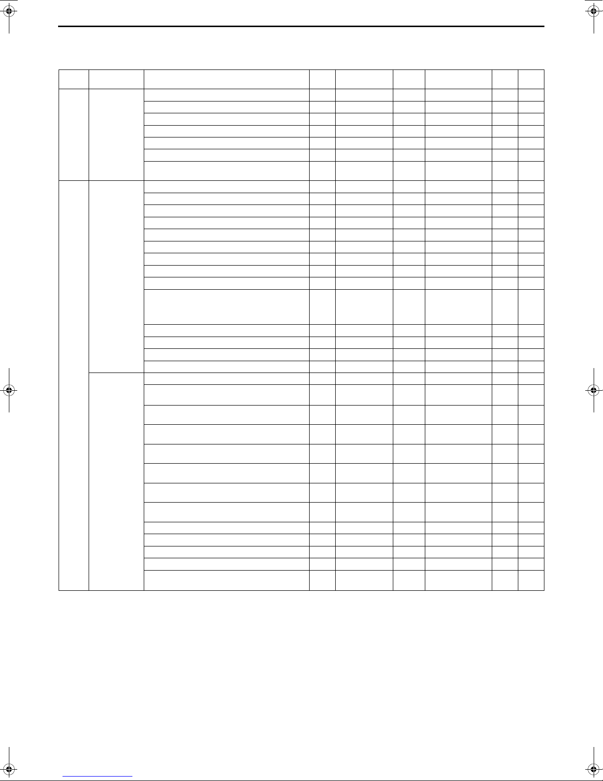
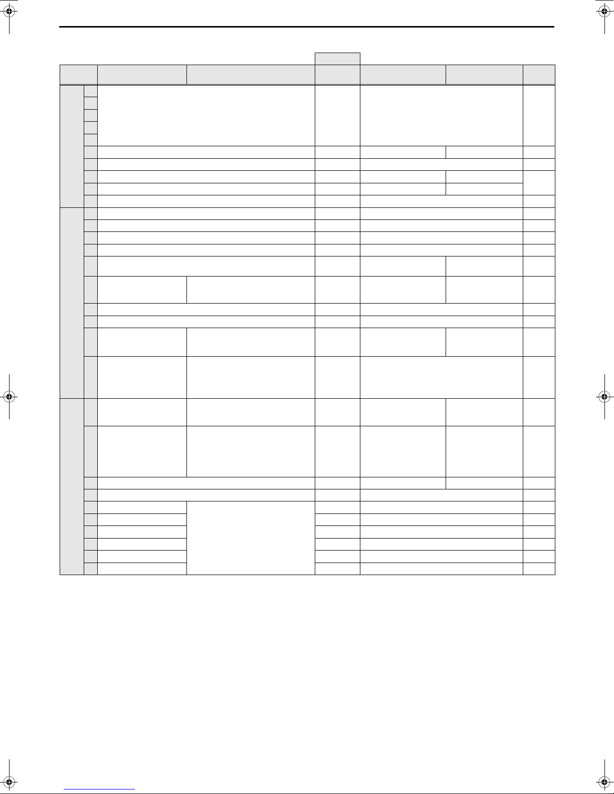
(2) Table of settings items
Set the dip switches SW2 and SW3 as shown in the table below to set the value for the items in the "Setting item" column.
Basic
settings
Basic
settings
Dip switch
settings
SW2-10: OFF
SW3-5, 6, 7: OFF
SW3-8, 9, 10: ON
SW2-10: OFF
SW3-5~8, 10:
OFF
SW3-9: ON
SW2-10: OFF
SW3-5~7, 9, 10:
OFF
SW3-8: ON
Setting item
Unit address 105 - 1 8 2
Number of connected GS to M-NET 106 - 0 16 1
AE-200 connection (0: Not connected, 2: Connected) 107 - 0 2 0
Function 1 (Sub sensor: 2, Main sensor: 1, Sub unit: 0) 110 - 0 2 0
M-NET address of main sensor of own tank 111 - 1 50 1
Address of sensor connection unit 112 - 1 51 51
Secondary control availability
(0: Not available 1: Available)
Model display 0 - - - -
Current time 1 Hour and minutes 0:00 23:59 -
Current inlet water temperature (display function only) c01 ºC - - -
Current outlet water temperature (display function only) c02 ºC - - -
Outdoor temperature (display function only) c03 ºC - - -
Storage tank water temperature (display function only) c04 ºC - - -
Demand control - maximum capacity setting 2 % 0 100 100
Demand control - start time 3 Hour and minutes 0:00 23:59 13:00
Demand control - end time 4 Hour and minutes 0:00 23:59 16:00
Outlet hot water temperature (boiling temperature) 9 ºC 40
High- and low-pressure display interval P 1051 Seconds 0 100 3
Low noise operation - maximum capacity 1054 % 0 100 70
Low noise operation - start time 1058 Hour and minutes 0:00 23:59 0:00
Low noise operation - end time 1059 Hour and minutes 0:00 23:59 0:00
Thermo-ON prohibition time Sjs1 1025 Seconds 0 480 60
Sensor method setting
(0: Local control, 1: Three-sensor, 2: Six-sensor)
Mode 1 Thermo-ON thermistor selection 1500 - 1
Mode 1 Thermo-OFF thermistor selection 1501 - 1
Mode 2 Thermo-ON thermistor selection 1502 - 1
Mode 2 Thermo-OFF thermistor selection 1503 - 1
Mode 3 Thermo-ON thermistor selection 1504 - 1
Mode 3 Thermo-OFF thermistor selection 1505 - 1
Number of water control modes 1507 - 1 3 1
Mode 1 Thermo differential value 1508 - 0 30 10
Mode 2 Thermo differential value 1509 - 0 30 10
Mode 3 Thermo differential value 1510 - 0 30 10
Anti-freezing setting
(0: Outdoor, 1: Indoor)
Item
code
121 - 0 1 0
1214 - 0 2 0
1514 - 0 1 0
Unit
Lower
limit
Upper limit
Secondary contlol
disabled: 90.0
Secondary contlol
enabled: 80.0
Six-sensor system: 6
Other system: 3
Six-sensor system: 6
Other system: 3
Six-sensor system: 6
Other system: 3
Six-sensor system: 6
Other system: 3
Six-sensor system: 6
Other system: 3
Six-sensor system: 6
Other system: 3
Initial
value
65
3
3
1
2
1
3
Setting
value
26
Page 27

(3) System configuration procedures: Individual system
A
ON
1
2345678910
ON
1
2345678910
ON
1
2345678910
10’s digit (0) 1 ’s digit (1)
(0)
10’s digit (0) 1’s digit (1)
(0)
1. Set the dip switches on the MAIN circuit board.
Set the dip switches (labeled A in the figure at right) that correspond to the
local system.
Refer to “Factory Switch Settings (Dip switch settings table)” (page 24) for
further details.
• When AE-200 is connected, set the dip switch 2-9 to ON.
2. Switch on the power to the unit.
Check for loose or incorrect wiring, and then switch on the power to the
unit.
When the power is switched on, the following codes will appear on the LED:
• [EEEE] will appear on LED1 in the circuit board (labeled A in the figure
at right).
[--ng] is displayed before the water flow rate adjustment operation is
performed. Cancel the [--ng] display by using one of the following
methods.
•Press SWP3.
•Press SWP1 or SWP2.
A
ON
ON
1
2345678910
ON
1
1
2345678910
2345678910
27
Page 28

3. Set the preset values with the switches on the circuit board.
10’s digit (0) 1’s digit (1)
(0)
B
(1) Set the dip switches SW2 and SW3 by following the procedure in
page 49. (Set the dip switches 3-8, 3-9, and 3-10 to ON.)
* [EEEE] will disappear, and an item code ([101]) will appear on LED1
(labeled B in the figure at right).
(2) Use SWP3 to toggle through the item codes and select an item code to
ON
1
1
2345678910
2345678910
change its current value. (The item codes will appear in the following
order: [101][104][105][106] [107]....)
(3) Use SWP1 to increase the value and SWP2 to decrease the value.
(4) Press SWP3 to save the changed value.
(5) Set the dip switches 3-8, 3-9, and 3-10 to OFF.
(6)
When connecting AE-200, perform the procedures described in 4 on
A
page 31.
Following the steps above, set the value for the following items as necessary.
[101] Not used
[104] Not used
[105] Function setting (When AE-200 is not connected to QAHV, the values set by rotary switches SWU1 and SWU2
are set as the preset values. When AE-200 is connected to QAHV, set the preset values referring to the notes
below.)
[106] Total number of units in the system (Initial value: 1) (Leave it as it is.)
[107] “2” when connected to AE-200 (Initial value: 0)
[108] Not used
[109] Not used
[110] Function setting (“1” when connected to AE-200) (Initial value: 0)
[111] M-NET address of main sensor of own tank (Initial value: 1)
[112 to 120] Not used
[121] Secondary side control is enabled when “1” is set. (Initial value: 0)
ON
ON
1
2345678910
ON
2345678910
1
The figure at left shows that the switches 1 through 5 are set to ON and 6 through 10 are set to OFF.
* When connecting AE-200 and remote controller (PAR-W31MAA) simultaneously, make the settings above, and
then turn off the power, turn it back on, and set “1” for item code [105]. After these settings, perform the
procedures described in (5) on page 32.
* Set SWS1 to OFF from the remote controller or with the local switch.
Settings cannot be changed unless the ON/OFF switch is set to OFF.
28
Page 29

(4) System configuration procedures : Multiple system
External
water
temperature
sensor
Field-supplied dry contact
switch/relay or remote
controller (PAR-W31MAA) or
centralized controller (AE-200)
SW2-9: ON
Address: 1
SW2-6: OFF
SW2-9: ON
Address: 2
SW2-6: OFF
SW2-9: ON
Address: 1 + n
Inter-unit wiring
(M-NET line)
* The main unit is the unit to which an external water temperature sensor is connected.
Main
unit
Sub unit
"n"th unit
Unit (MAIN circuit)
PCB
Unit (MAIN circuit)
PCB
Sub unit
Unit (MAIN circuit)
PCB
10’s digit (0) 1’s digit (1)
(0)
10’s digit (0) 1’s digit (1)
(0)
1. Set the dip switches and rotary switches.
(Switches on the main unit* AND on all sub units)
System configuration diagram
Setting the switches on the main unit
Set the dip switch SW2-9 to ON. (multiple unit control) (labeled A in the figure
at right)
Refer to “Factory Switch Settings (Dip switch settings table)” (page 24) for
further details.
Make sure the address of the main unit is set to "1" (labeled B in the figure at
right).
ON
2345678910
1
The figure at left shows that the switches 1 through 5 are set to ON and 6 through 10 are set to OFF.
Setting the switches on all sub units
(1) Set the dip switch SW2-9 to ON. (multiple unit control) (labeled A in the figure
at right)
(2) Set the addresses with the rotary switches. (labeled B in the figure at right).
Set the 10's digit with SWU1, and set the 1's digit with SWU2. Assign
sequential addresses on all sub units starting with 2.
(3) Set the dip switch SW2-6 to OFF. (power supply to communication circuit)
29
ON
ON
1
2345678910
ON
1
1
2345678910
2345678910
AB
ON
ON
1
2345678910
ON
1
1
2345678910
2345678910
AB
Page 30

2. Switch on the power to the unit.
ON
1
2345678910
ON
1
2345678910
ON
1
2345678910
[EEEE] [EEEE]
ON
1
2345678910
ON
1
2345678910
ON
1
2345678910
Main unit Sub unit
10’s digit (0) 1’s digit (1)
(0)
10’s digit (0) 1’s digit (2)
(0)
10’s digit (0) 1 ’s digit (1)
(0)
Check for loose or incorrect wiring, and then
switch on the power to all units.
When the power is switched on, the following
codes will appear on the LED:
• [EEEE] will appear on LED1 in the circuit
board.
3. Set the preset values with the switches on the circuit board.
(1) Set the dip switches SW2 and SW3 by following the procedure in
page 49. (Set the dip switches 3-8, 3-9, and 3-10 to ON.)
(2) Press either one of the push switches SWP1, 2, or 3 (labeled A in the
figure at right) on the circuit board.
* [EEEE] will disappear, and an item code ([101]) will appear on LED1
(labeled B in the figure at right).
(3) Use SWP3 to toggle through the item codes, and select an item code to
change its current value. (The item codes will appear in the following
order: [101] [104][105][106][107]....)
(4) Use SWP1 to increase the value and SWP2 to decrease the value.
(5) Press SWP3 to save the changed value.
(6) Set the dip switches 3-8, 3-9, and 3-10, to OFF.
A
B
ON
ON
1
2345678910
ON
1
1
2345678910
2345678910
Following the steps above, set the value for the following items with the switches on the circuit as necessary. Item
[106] must be set when multiple units are connected to a system.
[101] Not used
[104] Not used
[105] Function setting (When AE-200 is not connected to QAHV, the values set by rotary switches SWU1 and SWU2
are set as the preset values. When AE-200 is connected to QAHV, set the preset values referring to the notes
on page 31.)
[106] Total number of units in the system (Initial value: 1)
[107] “2” when connected to AE-200 (Initial value: 0)
[108] Not used
[109] Not used
[110] Function setting (Initial value: 0)
[111] M-NET address of main sensor of own tank (Initial value: 1)
[112] Address of sensor connection unit
[113 to 120] Not used
[121] Secondary side control is enabled when "1” is set. (Initial value: 0)
ON
2345678910
1
*For details of the setting, see page 43.
The figure at left shows that the switches 1 through 5 are set to ON and 6 through 10 are set to OFF.
30
Page 31

4. Perform an initial setup on the unit
Main unit
10’s digit (0) 1 ’s digit (1)
(0)
(1) Set the sub unit rotary switch SWU3 on the unit (labeled A in the figure
at right) to "F."
A
[EEEE] will appear in LED1 (labeled B in the figure at right). *1
(2) Press and hold the sub unit push switch (SWP3) (labeled C in the figure
at right) for one second or longer.
• While the system is starting up [9999] will appear on LED1 (labeled B in
the figure at right).
(3) Set the main unit rotary switch SWU3 on the unit (labeled A in the figure
B
ON
1
1
2345678910
2345678910
C
at right) to "F."
[EEEE] will appear in LED1 (labeled B in the figure at right). *1
(4) Press and hold the main unit push switch (SWP3) (labeled C in the
figure at right) for one second or longer.
• While the system is starting up [9999] will appear on LED1 (labeled B in the figure at right).
(5) When start-up is complete, a control property [0001] will appear.
• Then, five seconds later, [FFFF] will appear. *2
(6) Set the rotary switch SWU3 (labeled A in the figure at right) back to "0."
The start-up process is complete, and the settings for such items as clock, peak-demand control, schedule, and
thermistor settings can now be made.
*1 If the start-up process has already been completed, [FFFF] (instead of [EEEE]) will appear when the rotary switch
SWU3 is set to "F."
*2 [--ng] is displayed before the water flow rate adjustment operation is performed.
Refer to “2. Switch on the power to the unit.” on page 27 for how to cancel [--ng].
ON
ON
1
2345678910
ON
2345678910
1
The figure at left shows that the switches 1 through 5 are set to ON and 6 through 10 are set to OFF.
* When connecting AE-200 and remote controller (PAR-W31MAA) simultaneously, make the settings above, and
then turn off the power, turn it back on, and set “1” for item code [105] for the unit to which a remote controller
is connected. After these settings, perform the procedures described in (5) on page 32.
Slide switch (SWS1) settings
Individual system
SWS1 Setting Unit Operation
LOCAL Follows the input signal of the MAIN circuit
OFF Ignores the signal input
REMOTE Follows the input signal fed through a dry contact interface
Multiple system (SWS1 in the SUB circuit on both the main and sub units will be ineffective.)
SWS1 Setting Unit Operation
Main unit
MAIN circuit
LOCAL
OFF
REMOTE
Sub unit
MAIN circuit
LOCAL
OFF Ignores the signal input
REMOTE Follows the input signal of the Sub unit
LOCAL
REMOTE
LOCAL
OFF Ignores the signal input
REMOTE Follows the input signal of the Main unit
Follows the input signal of the Main unit
Follows the input signal fed through a dry
Main unit Sub unit
Follows the input signal of the Sub unit
Ignores the signal input Ignores the signal inputOFF
Follows the input signal of the Main unit
contact interface
31
Page 32

(5) Re-initializing the system
When the settings for the items below have been changed, the system will require re-initialization.
• Dip switch SW2-9 (multiple unit control)
• External signal input setting: Item codes [105], [106], [107], [110], [111], [112], [121], and [1214]
• Rotary switches (SWU1 and SWU2) (unit address)
Take the following steps to re-initialize the system:
(1) Set the rotary switch SWU3 to "F."
[FFFF] will appear in the LED1.
(2) Press and hold the push switch SWP3 for one second or longer.
• While the system is starting up [9999] will appear on LED1.
• When start-up is complete, a control property [0001] will appear.
• Then, five seconds later, [FFFF] will appear.*
*
If [EEEE] appears, perform the procedures in (2) again.
[--ng] is displayed before the water flow rate adjustment operation is performed.
(3) Set the rotary switch SWU3 back to "0."
(6) Resetting the system
Take the following steps to reset the system. An error can also be reset by taking the steps below.
When an error on the MAIN unit is reset, all sub units will stop.
(1) Set the rotary switch SWU3 to "F."
[FFFF] will appear in the LED1.
(2) Press and hold the push switch SWP3 for one second or longer.
• While the system is starting up [9999] will appear on LED1.
• When start-up is complete, a control property [0001] will appear.
• Then, five seconds later, [FFFF] will appear.
(3) Set the rotary switch SWU3 back to "0."
32
Page 33

[4] Air bleeding operation and flow rate adjustment operation during test run
SW1
89
ON OFF
SW1 SW3
893
ON OFF ON
(1)Air bleeding operation
Check there is no water leakage during operation.
For each circuit, perform at least three sets of at least 5 minutes in duration. During the air bleeding operation, use the
method below (*1) to display the water flow rate during operation and check it is stable (no air entrainment).
(1)-1. Primary side water circuit air bleeding operation
Step Contents Operation and check points Supplemental explanation
Check the water level is not the full level.
a Water level check
b Power operation Turn the power ON.
PCB DIP switch
c
setting
(Water is supplied even when the target water level
has been reached.)
Change the setting of SW1-8 from OFF to ON.
-
If the startup operation has not finished,
SW2-9 and SW2-3 need to be set as a
stopgap measure (see Note 1).
* Make sure SWS2 is set to the lower
side. (See page 23.)
Operation
d
procedure 2
e Stop operation 1
f Stop operation 2
Change the setting of PCB slide SWS1 from
REMOTE to LOCAL.
* When the pump sound has become quiet, end
operation.
Change the setting of PCB DIP SW1-8 from ON to
OFF.
Change the setting of PCB slide SWS1 from
LOCAL to REMOTE.
The compressor does not operate.
* The pump and motor-operated valve 2
are automatically set to OPEN (starting
water flow).
* The pump and motor-operated valve 2
are automatically set to CLOSED
(ending water flow).
-
(1)-2. Secondary side water circuit air bleeding operation
Step Contents Operation and check points Supplemental explanation
Check the water level is not the full level.
a Water level check
b Power operation Turn the power ON.
Operation
c
procedure 1
PCB DIP switch
d
setting
(Water is supplied even when the target water level
-
has been reached.)
If the startup operation has not finished,
SW2-9 and SW2-3 need to be set as a
stopgap measure (see Note 1).
Check that the secondary side control is enabled. For details, refer to page 28 (4-[3]-(3)-3).
Change the setting of SW1-8 from OFF to ON.
* Make sure SWS2 is set to the lower
side. (See page 23.)
Change the setting of PCB slide SWS1 from
e
Operation
procedure 2
REMOTE to LOCAL.
* When the pump sound has become quiet, end
operation.
f Stop operation 1
g Stop operation 2
Change the setting of PCB DIP SW1-8 and SW3-3
from ON to OFF.
Change the setting of PCB slide SWS1 from
LOCAL to REMOTE.
The compressor does not operate.
* The pump and motor-operated valve 2
are automatically set to OPEN (starting
water flow).
* The pump and motor-operated valve 2
are automatically set to CLOSED
(ending water flow).
-
33
Page 34

(*1) Water flow rate display method
SW2 SW3
-10-5-6-7-8-9-10
OFF OFF OFF OFF OFF ON ON
Multiple unit change-over switch
SW2-9
Local/internal change-over switch
SW2-3
When startup operation has not completed OFF ON
When startup operation has completed - -
1Set the PCB DIP switches as shown below.
2If the flow rate adjustment operation has never been performed, ‘ng’ appears on the PCB’s digital display after
the system startup operation. Press SWP1 (up) or SWP2 (down) to delete the ‘ng’ from the PCB’s digital display
(changing the display to a value such as 1).
3Press SWP3 repeatedly to change the code shown in the PCB’s display. The code changes with each press.
Continue pressing SWP3 until item code ‘C25’ is displayed in the PCB’s digital display.
4Once ‘C25’ is displayed, press SWP1 or SWP2 to display and check the current flow rate.
After displaying the flow rate, the display shows the current item code (*2) if SWP1 to SWP3 are not operated for
one minute. Display and check the current flow rate by pressing SWP1 or SWP2 again.
(*2) If the flow rate adjustment operation has never been performed, ‘ng’ appears in the PCB’s digital display
after the system startup operation. Press SWP1 or SWP2 to delete the ‘ng’ from the PCB’s digital display
(changing the display to ‘C25’).
(Note 1) As a stopgap measure, change the settings of SW2-9 and SW2-3 as shown in the table below, then restart
the power.
If water shutoff error 2601 occurs during the air bleeding operation, remove the cause of the problem, then change
the setting of PCB slide SWS1 from LOCAL to OFF, and back to LOCAL again. The air bleeding operation starts.
(You can clear water shutoff error by turning the power OFF and ON again. The equipment enters standby mode in
this case.)
(You can also clear water shutoff errors by changing the setting of PCB DIP SW1-8 or 1-9 from ON to OFF. Turning
DIP SW1-8 OFF starts circulation heating circuit air bleeding (manual). Turning DIP SW1-9 OFF starts water
supply circuit air bleeding (manual).)
34
Page 35

(2)Water flow rate adjustment operation (when the secondary side control is disabled)
SW2 SW3
-10-5-6-7-8-9-10
OFF OFF OFF OFF OFF ON ON
Step Contents Operation and check points Supplemental explanation
a Water level check
b Power operation Turn the power ON.
Operation
c
procedure
Operation
d
procedure
e Stop operation 1 Change the setting of SW1-6 from ON to OFF. -
f Stop operation 2
Check the water level is neither at the full or
empty level.
Change the setting of PCB slide SWS1 from
REMOTE to LOCAL.
Change the setting of SW1-6 from OFF to ON.
Change the setting of PCB slide SWS1 from
LOCAL to REMOTE.
Water is supplied even when the target water level
has been reached.
If the startup operation has not finished, SW2-9
and SW2-3 need to be set as a stopgap measure
(see Note 1).
If this flow rate adjustment operation has never
been performed ‘--ng’ is displayed.
* Make sure SWS2 is set to the lower side. (See
page 23.)
* Step c and Step d must be taken in sequence to
run the flow-adjustment operation.
* The pump operation and flow rate adjustment
valve opening are automatically adjusted, and
the flow rate is measured in 30 second intervals.
* You can check whether this flow rate adjustment
operation has ended or is underway using the
setting given in Note 2.
-
Checking the flow rate after the flow rate adjustment operation
The flow rate adjustment operation adjusts the pump output and water flow rate valve opening to determine how to
match the flow rate characteristic to the local circuit. Use the method below (*3 1 to 4) to check the operation
result (characteristic).
If air bleeding was not done fully and the map not created properly, a water shutoff error, high pressure
error or other problems will occur when operating the system. Check the points below in this case. If the
values are abnormal, redo the air bleeding and flow rate adjustment operations.
(*3)
1Set the PCB’s DIP switches as shown below.
2Press SWP3 repeatedly to change the code shown in the PCB’s display. The code changes with each
press (*4).
Continue pressing SWP3 until ‘dxx’ is displayed in the PCB’s digital display.
(‘dxx’ is a code that stores the flow rate for a given pump output opening and valve opening. See Table 1.)
(*4) If the flow rate adjustment operation has never been performed, ‘ng’ appears after the system startup
operation. Perform the flow rate adjustment operation in this case.
35
Page 36

3Press SWP1 or SWP2 to display the operation result (flow rate characteristic) corresponding each flow rate code
Close <------------------ Water flow rate adjust valve opening ------------------> Open
Pump output opening/water flow rate
adjust valve opening
1600 1400 1200 1000 800 600 400 200 100
Flow rate (pump output opening 16%) d01 d02 d03 d04 d05 d06 d07 d08 d09
Flow rate (pump output opening 27%) d10 d11 d12 d13 d14 d15 d16 d17 d18
Flow rate (pump output opening 100%) d19 d20 d21 d22 d23 d24 d25 d26 d27
Close <------------------ Water flow rate adjust valve opening ------------------> Open
Pump output opening/water flow rate
adjust valve opening
1600 1400 1200 1000 800 600 400 200 100
Flow rate (pump output opening 16%)
Flow rate (pump output opening 27%)
Flow rate (pump output opening 100%)
Multiple unit change-over switch
SW2-9
Local/internal change-over switch
SW2-3
When startup operation has not completed OFF ON
When startup operation has completed - -
Water flow rate adjustment operation status Display
Not completed - - n g
Completed - - - g
In operation - i n g
SW2 SW3
-10-5-6-7-8-9-10
ON OFF OFF OFF ON ON OFF
‘dxx’ in Table 1 and write them down.
Table 1
<Check result>
4Check the following.
↓ Check the checkbox.
□ All places with flow rate valve opening 1000 through 100 are 2 L or above?
If 2 L/min or below, air may not be bled out. Perform an air bleeding operation and water flow rate
adjustment operation again.
□ When there are multiple units, the values of the same pump output opening and the same valve opening
are not greater or less than those for other units by 10% and 2 L/min or more.
(In multiple-unit system, perform a water flow rate adjustment operation at the same time.)
□ All the values (item codes d01 through d09) are not “0” when the pump output opening is 16%. (Not
whole air is bled out.)
(Note 1) Change SW2-9 and SW2-3 as a stopgap procedure as shown in the table below, and then turn the power
on.
(Note 2) The table below shows the water flow rate adjustment operation status in 4 figures when the PCB DIP
switch is set as shown in Note 3.
(Note 3) PCB DIP switch settings
36
Page 37

(3)Water flow rate adjustment operation (when the secondary side control is enabled)
Step Contents Operation and check points Supplemental explanation
a Water level check
b Power operation Turn the power ON.
c Operation procedure 1
d Operation procedure 2
e Operation procedure 3
f Stop operation 1
g Stop operation 2
Check the water level is neither at the full or
empty level.
Check that the secondary side control is
enabled.
Change the setting of PCB slide SWS1 from
REMOTE to LOCAL.
Change the setting of SW1-6 from OFF to
ON.
Change the setting of SW1-6 from ON to
OFF.
Change the setting of PCB slide SWS1 from
LOCAL to REMOTE.
Water is supplied even when the target
water level has been reached.
If the startup operation has not finished,
SW2-9 and SW2-3 need to be set as a
stopgap measure (see Note 1).
If this flow rate adjustment operation has
never been performed ‘--ng’ is displayed.
For details, refer to page 28 (4-[3]-(3)-3).
* Make sure SWS2 is set to the lower side.
(See page 23.)
* Step d and Step e must be taken in
sequence to run the flow-adjustment
operation.
The pump operation and flow rate
adjustment valve opening are automatically
adjusted, and the flow rate is measured in
30 second intervals.
You can check whether this flow rate
*
adjustment operation has ended or is
underway using the setting given in Note 2.
-
-
Checking the flow rate after the flow rate adjustment operation
The flow rate adjustment operation adjusts the pump output and water flow rate valve opening to determine how
to match the flow rate characteristic to the local circuit. Use the method below (*3 1 to 4) to check the
operation result (characteristic).
If air bleeding was not done fully and the map not created properly, a water shutoff error, high pressure
error or other problems will occur when operating the system. Check the points below in this case. If the
values are abnormal, redo the air bleeding and flow rate adjustment operations.
(*3)
1 Set the PCB’s DIP switches as shown below.
SW2 SW3
-10-5-6-7-8-9-10
OFF OFF OFF OFF OFF ON ON
2 Press SWP3 repeatedly to change the code shown in the PCB’s display. The code changes with each press
(*4).
Continue pressing SWP3 until ‘dxx’ is displayed in the PCB’s digital display.
(‘dxx’ is a code that stores the flow rate for a given pump output opening and valve opening. See Table 1.)
(*4) If the flow rate adjustment operation has never been performed, ‘ng’ appears after the system startup
operation. Perform the flow rate adjustment operation in this case.
3 Press SWP1 or SWP2 to display the operation result (flow rate characteristic) corresponding each flow rate
code ‘dxx’ in Table 1 and write them down.
37
Page 38

Table 1
Primary side circuit flow rate map
Close <------------------ Water flow rate adjust valve opening ------------------> Open
Pump output opening/water flow rate
adjust valve opening
Flow rate (pump output opening 16%) d01 d02 d03 d04 d05 d06 d07 d08 d09
Flow rate (pump output opening 27%) d10 d11 d12 d13 d14 d15 d16 d17 d18
Flow rate (pump output opening 100%) d19 d20 d21 d22 d23 d24 d25 d26 d27
1600 1400 1200 1000 800 600 400 200 100
(Check result)
<------------------ Water flow rate adjust valve opening ------------------>Open
Close
Pump output opening/water flow rate
adjust valve opening
Flow rate (pump output opening 16%)
Flow rate (pump output opening 27%)
Flow rate (pump output opening 100%)
1600 1400 1200 1000 800 600 400 200 100
4-1 Check the following. (Primary side circuit)
Primary side circuit
↓ Check the checkbox.
□ All places with flow rate valve opening 1000 through 100 are 2 L or above?
If 2 L/min or below, air may not be bled out. Perform an air bleeding operation and water flow rate
adjustment operation again.
□ When there are multiple units, the values of the same pump output opening and the same valve opening
are not greater or less than those for other units by 10% and 2 L/min or more.
(In multiple-unit system, perform a water flow rate adjustment operation at the same time.)
□ All the values (item codes d01 through d09) are not “0” when the pump output opening is 16%. (Not
whole air is bled out.)
Table 2
Secondary side circuit flow rate map
Pump output value0 5 101520253035404550
Flow rate d55 d56 d57 d58 d59 d60 d61 d62 d63 d64 d65
Pump output value556065707580859095100
Flow rate d66 d67 d68 d69 d70 d71 d72 d73 d74 d75
(Check result)
Pump output value0 5 101520253035404550
Flow rate
Pump output value556065707580859095100
Flow rate
4-2 Check the following. (Secondary side circuit)
↓ Check the checkbox.
□ Is the output at 100% (d75) between 20 ℓ/min and 30 ℓ/min?
If the output is below 20 ℓ/min, water may not flow at a high flow rate during normal operation.
If the output is above 30 ℓ/min, water may not flow at a low flow rate during normal operation.
• Take a measure such as adjusting the frequency using an inverter, etc. so that the output at 100% (d75)
becomes between 20 /min and 30 /min.
□ Does a value from 1 ℓ/min to 4 ℓ/min exist for the flow rate at an arbitrary output except 0%?
If there was no value from 1 ℓ/min to 4 ℓ/min for the flow rate when any output except 0%, the flow rate
may not be able to be controlled at a low flow rate.
• Carry out the air bleeding and flow rate adjustment operations again.
• Take a measure such as adjusting the frequency using an inverter, etc. so that a value from 1 /min to 4 /min
exists for the flow rate during output.
38
Page 39

(Note 1) Change SW2-9 and SW2-3 as a stopgap procedure as shown in the table below, and then turn the power on.
Multiple unit change-over switch
SW2-9
When startup operation has not completed OFF ON
When startup operation has completed - -
Local/internal change-over switch
SW2-3
(Note 2) The table below shows the water flow rate adjustment operation status in 4 figures when the PCB DIP switch
is set as shown in Note 3.
Water flow rate adjustment operation status Display
Not completed --ng
Completed ---g
In operation -ing
(Note 3) PCB DIP switch settings
SW2 SW3
-10-5-6-7-8-9-10
ON OFF OFF OFF ON ON OFF
39
Page 40

(1) Sensor method settings
SW2 SW3
-10 5 6 7 8 9 10
OFF OFF OFF OFF ON OFF OFF
0: Local control method
1: Three-sensor method
2: Six-sensor method
* PAR-W31MAA or AE-200 is required when three-sensor or six-sensor method is used.
Item code Increments Lower limit Upper limit Initial value
Sensor method setting 12141020
Step 0
Set the ON/OFF
switch (SWS1) to
OFF.
Step 1
Set the dip switches
SW2 and SW3.
Step 2
Select the desired
item with the push
switch SWP3.
Step 3
Press the push
switches SWP1 ()
or SWP2 () to
increase or
decrease the value.
Step 4
Press the push
switch SWP3 to
save the change.
Set SWS1 to OFF from the remote controller or with the local switch.
Settings cannot be changed unless the ON/OFF switch is set to OFF.
Set the dip switches on the circuit board as follows before making the settings for the items
described in this section.
The item codes shown in the table below will appear in order every time the push switch
SWP3 is pressed.
Use the push switches SWP1 and SWP2 to change the value of the selected item.
The value will keep blinking while it is being changed.
Press SWP3 once within one minute of changing the setting with SWP1 or SWP2 to save the
setting.
Once the new setting is saved, the display will stop blinking and stay lit. The display will, then,
return to the item code display mode.
If SWP3 is not pressed within one minute, the change will not be saved and the display will
return to the item code display mode.
* When using multiple units, configure the same settings for each unit.
* When “Local control method” is selected, hot water storage operation ON/OFF control is performed by ON/OFF status of TB6 32-33.
40
Page 41

(2) Three-sensor method or six-sensor method setting
SW2 SW3
-10 5 6 7 8 9 10
OFF OFF OFF OFF ON OFF OFF
Settings table
* Only for six-sensor method
Thermistor number 1: TH15, 2: TH16, 3: TH17
* Set the item code 1507 to “3” when using all modes (Mode 1, 2, and 3).
Set the item code 1507 to “2” when using mode 1 and mode 2.
Set the item code 1507 to “1” when using mode 1.
Items that can be set
Item
code
Initial
value
Unit
Limits and increments
Increments Lower limit Upper limit
Mode 1 Thermo-ON thermistor selection 1500 3 - 1 1 3 (6*)
Mode 1 Thermo-OFF thermistor selection 1501 3 - 1 1 3 (6*)
Mode 2 Thermo-ON thermistor selection 1502 1 - 1 1 3 (6*)
Mode 2 Thermo-OFF thermistor selection 1503 2 - 1 1 3 (6*)
Mode 3 Thermo-ON thermistor selection 1504 1 - 1 1 3 (6*)
Mode 3 Thermo-OFF thermistor selection 1505 3 - 1 1 3 (6*)
Number of water control modes 1507 1 - 1 1 3
Mode 1 Thermo differential value 1508 10 ºC 1 0 30
Mode 2 Thermo differential value 1509 10 ºC 1 0 30
Mode 3 Thermo differential value 1510 10 ºC 1 0 30
Use the separately sold thermistor (TW-TH16E) to control the water temperature in the storage tank.
Setting procedures
Step 0
Set the ON/OFF
switch (SWS1) to
OFF.
Step 1
Set the dip switches
SW2 and SW3.
Set SWS1 to OFF from the remote controller or with the local switch.
Settings cannot be changed unless the ON/OFF setting is set to OFF. *
Step 2
Select the desired
item with the push
switch SWP3.
Step 3
Press the push
switches SWP1 ()
or SWP2 () to
increase or
decrease the value.
Step 4
Press the push
switch SWP3 to
save the change.
Item codes 1500 through 1510 relate to sensor method setting.
Press the push switch SWP3 to select an item code.
Use the push switches SWP1 and SWP2 to change the value of the selected item.
The value will keep blinking while it is being changed.
Press SWP3 once within one minute of changing the setting with SWP1 or SWP2 to save the
setting.
Once the new setting is saved, the display will stop blinking and stay lit. The display will, then,
return to the item code display mode.
If SWP3 is not pressed within one minute, the change will not be saved and the display will
return to the item code display mode.
41
Page 42

Usage example
TH15 temperature < (Set water
temperature - Mode 1 Thermo
differential value [Code: 1508])
Unit operation start
Ta nk
TH17
Tank
TH16
TH15
TH17
TH16
TH15
TH17 temperature >
Set water temperature
Unit operation stop
* Set the operation mode and water
temperature from the remote controller
PAR-W31MAA.
Operation example (Three-sensor method - when a remote controller PAR-W31MAA is used)
Operation mode: Mode 1
Mode 1 Thermo-ON thermistor selection (Item code 1500): 1
Mode 1 Thermo-OFF thermistor selection (Item code 1501): 3
* Use the separately sold TW-TH16E temperature thermistor.
Two or more units are needed to use the six-sensor method.
* Make sure to set the unit outlet hot water temperature.
42
Page 43

Referring to the figure below, configure the settings for each unit according to the system.
123
PAR-W31
Storage tank
M-NET cable
* SW2-9: ON (When multiple units are connected)
Address
Item code
106 110 111 1214
13111
23011
33011
123
AE-200
PAR-W31
Storage tank
M-NET cable
* SW2-9: ON (When multiple units are connected)
* When a remote controller is not connected, the setting for
item code [105] is not required.
Address
Item code
105 106 107 110 111 1214
1 132111
2 232011
3 332011
123
PAR-W31
Storage tank
M-NET cable
Address
Item code
106 110 111 112 1214
1 31122
2 321-2
3 301-2
* SW2-9: ON
123
AE-200
PAR-W31
Storage tank
M-NET cable
* SW2-9: ON
* When a remote controller is not connected, the setting for
item code [105] is not required.
Address
Item code
105 106 107 110 111 112 1214
1 1321122
2 23221 - 2
3 33201 - 2
Three-sensor method
Six-sensor method
* For how to make item code settings, refer to page 40.
43
Page 44

(3) Setting the outlet hot water temperature
SW2 SW3
-10 5 6 7 8 9 10
OFF OFF OFF OFF OFF ON OFF
Settings table
0: Outlet Hot Water Temp. input PCB or PAR-W31MAA or AE-200
1: Outlet Hot Water Temp. input IT terminal
2: Outlet Hot Water Temp. input 4-20 mA (Analog input)
Items that can be set
Item
code
Initial
value
Unit
Setting
Setting change
from an optional
remote controller
Increments
Lower
limit
Upper
limit
Setting method selection 1073 0 - 1 0 2 Not possible
1 Selecting the outlet hot water temperature setting method
Select one of the following three outlet hot water temperature setting methods.
Setting procedures
Step 0
Set the ON/OFF
switch (SWS1) to
OFF.
Set SWS1 to OFF from the remote controller or with the local switch.
Settings cannot be changed unless the ON/OFF setting is set to OFF. *
Step 1
Set the dip switches
Set the dip switches on the circuit board as follows before making the settings for the items
described in this section.
SW2 and SW3.
Step 2
Select the desired
item with the push
Press the push switch SWP3 to select item code 2.
Press the push switches SWP1 or SWP2 to change the value of the selected item.
The value will keep blinking while it is being changed.
switch SWP3.
Step 3
Press the push
switches SWP1 ()
or SWP2 () to
increase or
decrease the value.
Step 4
Press the push
switch SWP3 to
save the change.
Press SWP3 once within one minute of changing the setting with SWP1 or SWP2 to save the
setting.
Once the new setting is saved, the display will stop blinking and stay lit. The display will, then,
return to the item code display mode.
If SWP3 is not pressed within one minute, the change will not be saved and the display will
return to the item code display mode.
* Configure the settings for all units even when controlling multiple units.
44
Page 45

2 Outlet hot water temperature setting method from PCB
SW2 SW3
-10 5 6 7 8 9 10
OFF OFF OFF OFF OFF ON OFF
Settings table
* This becomes the secondary side outlet hot water temperature when the secondary side
control is enabled.
* Secondary control disabled: 90ºC, Secondary control enabled: 80ºC
Items that can be set
Item
code
Initial
value
Unit
Setting
Setting change
from an optional
remote controller
Increments
Lower
limit
Upper
limit
Outlet Hot Water Temp. setting 9 65 ºC 0.5 40 *90 (80) Possible
Setting procedures
Step 0
Set the ON/OFF
Set SWS1 to OFF from the remote controller or with the local switch.
Settings cannot be changed unless the ON/OFF setting is set to OFF. *
switch (SWS1) to
OFF.
Step 1
Set the dip switches
SW2 and SW3.
Step 2
Select the desired
item with the push
switch SWP3.
Step 3
Press the push
switches SWP1 ()
or SWP2 () to
increase or
decrease the value.
Step 4
Press the push
switch SWP3 to
save the change.
Set the dip switches on the circuit board as follows before making the settings for the items
described in this section.
Press the push switch SWP3 to select item code 2.
Press the push switches SWP1 or SWP2 to change the value of the selected item.
The value will keep blinking while it is being changed.
Press SWP3 once within one minute of changing the setting with SWP1 or SWP2 to save the
setting.
Once the new setting is saved, the display will stop blinking and stay lit. The display will, then,
return to the item code display mode.
If SWP3 is not pressed within one minute, the change will not be saved and the display will
return to the item code display mode.
3Settings from PAR-W31MAA
Refer to page 75.
45
Page 46

4Settings using Analog input
Remote water temperature setting input signal type
Analog input type can be selected from the following four types:
"0": 4-20 mA
"1": 0-10 V
"2": 1-5 V
"3": 2-10 V
Select item code 1075 to set the type of analog input signal to be used to set the water temperature from a remote
location.
Setting procedures
Set the dip switches on the circuit board as follows to change the settings.
Step 1
Set dip switches SW2, SW3,
SW421-1, and SW421-2.
SW421-1 SW421-2
4-20 mA ON ON
0-10 V OFF OFF
1-5 V OFF ON
2-10 V OFF OFF
SW2 SW3
-105678910
Switch settings OFF OFF OFF OFF OFF ON OFF
Step 2
Select the item to be set with
push switch SWP3.
Select the type of analog input signal to be used to set the water temperature from a remote location.
Step 3
Change the values with push
switches SWP1 () or SWP2 ().
Press push switch SWP3 to select the item code.
Change the values with push switches SWP1 and SWP2.
Until the changed values are saved, the values will blink.
Items that can be set
Water temperature
setting input signal type
Item
code
Initial
value
Unit
Increments
Setting
Lower
limit
Upper
limit
Note
1075 0 1 0 3 Not possible
Setting change from
an optional remote
controller
Step 4
Press push switch SWP3 to save
the changed value.
Press SWP3 once within one minute of changing the settings to save the change.
When the new setting is saved, the display will stop blinking and stay lit. The display will, then, return to the item code
display mode.
If SWP3 is not pressed within one minute, the change will not be saved, and the display will return to the item code
display mode.
46
Page 47

Setting the water temperature using analog signal input
temp B 90ºC
temp A 40ºC
5.9 mA Input current18.3 mA
Preset temperature = (B - A) * (Input current - 5.9 mA) / 12.4 mA + A
Change of 0.12 mA or less is not recognized.
temp B 90ºC
temp A 40ºC
1.0 V Input voltage9.1 V
Preset temperature = (B - A) * (Input voltage - 1.0 V) / 8.1 V + A
Change of 59 mV or less is not recognized.
temp B 90ºC
temp A 40ºC
1.5 V Input voltage4.5 V
Preset temperature = (B - A) * (Input voltage - 1.5 V) / 3.0 V + A
Change of 29 mV or less is not recognized.
temp B 90ºC
temp A 40ºC
2.9 V Input voltage9.1 V
Preset temperature = (B - A) * (Input voltage - 2.9 V) / 6.2 V + A
Change of 59 mV or less is not recognized.
Select the analog input format
• When the water temperature setting input signal type is set to 0 (4-20 mA)
• External analog input signal of between 5.9 and 18.3 mA: the preset temperature will be linearly interpolated.
• When the water temperature setting input signal type is set to 1 (0-10 V)
• External analog input signal of between 1.0 and 9.1 V: the preset temperature will be linearly interpolated.
• When the water temperature setting input signal type is set to 2 (1-5 V)
• External analog input signal of between 1.5 and 4.5 V: the preset temperature will be linearly interpolated.
• When the water temperature setting input signal type is set to 3 (2-10 V)
• External analog input signal of between 2.9 and 9.1 V: the preset temperature will be linearly interpolated.
47
Page 48

(4) Scheduled operation
SW2 SW3
-10 5 6 7 8 9 10
OFF OFF OFF OFF OFF ON OFF
Settings table
Items that can be set
Item
code
Initial
value
Unit
Setting
Setting change
from an optional
remote controller
Increments
Lower
limit
Upper
limit
Maximum capacity setting 2 100 % 5% 0 100 Not possible
Peak-demand control start time 3 13:00 Hour: minute 1 0000 2359 Not possible
Peak-demand control end time 4 16:00 Hour: minute 1 0000 2359 Not possible
Configure the schedule settings using a remote controller (PAR-W31MAA) or a system controller (AE-200).
(5) Peak-demand control operation
Peak-demand control is a function used to control the power consumptions of the units during peak-demand hours.
The number of units in operation and the compressor's maximum operating frequency will be controlled
according to the peak-demand control signal.
Individual system control Multiple system control
Individual unit control
Maximum frequency = Maximum capacity under peak-
demand control
Setting procedures
Set the maximum capacity setting on the circuit board.
Step 0
Set the ON/OFF
Set SWS1 to OFF from the remote controller or with the local switch.
Settings cannot be changed unless the ON/OFF setting is set to OFF. *
switch (SWS1) to
OFF.
Depending on the peak-demand control setting that is
made on the main unit, the number of units in operation
and the maximum operating frequency of the units in
operation will be adjusted.
Step 1
Set the dip switches
SW2 and SW3.
Step 2
Select the desired
item with the push
switch SWP3.
Step 3
Press the push
switches SWP1 ()
or SWP2 () to
increase or
decrease the value.
Step 4
Press the push
switch SWP3 to
save the change.
Set the dip switches on the circuit board as follows before making the settings for the items
described in this section.
Press the push switch SWP3 to select item code 2.
Press the push switches SWP1 or SWP2 to change the value of the selected item.
The value will keep blinking while it is being changed.
Press SWP3 once within one minute of changing the setting with SWP1 or SWP2 to save the
setting.
Once the new setting is saved, the display will stop blinking and stay lit. The display will, then,
return to the item code display mode.
If SWP3 is not pressed within one minute, the change will not be saved and the display will
return to the item code display mode.
(*) If the peak-demand control contact is ON, units will operate at the maximum capacity that
was set in the steps above.
*
The maximum frequency may be restricted depending on the inputs of maximum demand capacity and
maximum low-noise capacity. Refer to page 73 for details.
48
Page 49

(6) Setting the total number of units for a multiple system
SW2 SW3
-10 5 6 7 8 9 10
OFF OFF OFF OFF ON ON ON
Setting table
*1 Enter the total number of units including the main unit. Applicable only to the main unit.
*2 0: Sub unit
1: Main sensor
2: Sub sensor (For six-sensor method)
*3 Set the address of the sub sensor for six-sensor method.
*4 0: Secondary side control disabled
1: Secondary side control enabled
Item code Increments Lower limit Upper limit Initial value
Unit address 1051182
Total number of units in the system*1 106 1 0 16 1
AE-200 connection 107 2020
Own unit role*2 1101020
Main sensor address 111 1 1 50 1
Sub sensor address*3 112 1 1 51 51
Secondary circuit control*4 121 1010
Note The new setting will not be saved unless a reset is performed.
Step 0
Set the ON/OFF
switch (SWS1) to
OFF.
Step 1
Set the dip switches
SW2 and SW3.
Step 2
Select the desired
item with the push
switch SWP3.
Step 3
Press the push
switches SWP1 ()
or SWP2 () to
increase or
decrease the value.
Set SWS1 to OFF from the remote controller or with the local switch.
Settings cannot be changed unless the ON/OFF switch is set to OFF.
Set the dip switches on the circuit board as follows to select how external inputs are received.
The item codes shown in the table below will appear in order every time the push switch
SWP3 is pressed.
Use the push switches SWP1 and SWP2 to change the value of the selected item.
The value will keep blinking while it is being changed.
Step 4
Press the push
switch SWP3 to
save the change.
Press SWP3 once within one minute of changing the setting with SWP1 or SWP2 to save the
setting.
Once the new setting is saved, the display will stop blinking and stay lit. The display will, then,
return to the item code display mode.
If SWP3 is not pressed within one minute, the change will not be saved and the display will
return to the item code display mode.
Step 5
Turn the power back
After changing the settings, re-initialize the system according to the procedures detailed on
page 32.
on.
Reset the system.
Setting the unit addresses
Refer to “(4) System configuration procedures : Multiple system” (page 29).
49
Page 50

(7) Selecting the item that normally appears on the LED
The dot lights up when the operation signal is on.
The dot lights off when the operation signal is off.
"A" will be displayed while the compressor is in operation.
"S" will be displayed while the compressor is stopped.
"S" will be displayed while the fan is forced to operate.
"-" will be displayed when this function is disabled.
"d" will be displayed when the peak-demand control function is enabled.
"-" will be displayed when this function is disabled.
Displays the operation mode.
"H" will be displayed during water-heating operation.
"d" will be displayed during a defrost cycle.
"F" will be displayed while the pump is being operated to prevent freeze-up.
Displays the system control mode.
"S" will be displayed when the multiple system control option is used.
"A" will be displayed when the individual system control option is used.
SW2 SW3
-10 5 6 7 8 9 10
OFF OFF OFF ON OFF OFF OFF Displays the operation mode.(*1)
OFF OFF ON ON OFF OFF OFF Displays the operation mode.(*2)
OFF ON ON OFF OFF OFF OFF Displays the current water temperature.
OFF ON OFF OFF OFF OFF OFF Displays the water-temperature setting.
OFF OFF OFF OFF OFF OFF OFF Displays the high and low refrigerant pressures.
(*1)
Display content
(*2)
50
Page 51

5. Electrical Wiring Installation
[1] Main Power Supply Wiring and Switch Capacity
Schematic Drawing of Wiring (Example)
A: Switch (with current breaking
capability)
3N~380–415V
L
1, L2, L3, N
B: Current leakage breaker
C: Outdoor unit
Main power supply wire size, switch capacities, and system impedance
Model
QAHV-N560YA-HPB 10 - 10 63 A 100 mA 0.1 sec. or less 63 63 63 0.21
Minimum wire thickness (mm
Main cable Branch Ground Capacity Fuse
2
)
Current leakage breaker
1. Use a dedicated power supply for each unit. Ensure that each unit is wired individually.
2. When installing wiring, consider ambient conditions (e.g., temperature, sunlight, rain).
3. The wire size is the minimum value for metal conduit wiring. If voltage drop is a problem, use a wire that is
one size thicker.
Make sure the power-supply voltage does not drop more than 10%.
4. Specific wiring requirements should adhere to the wiring regulations of the region.
5. Power supply cords of appliances for outdoor use shall not be lighter than polychloroprene sheathed
flexible cord (design 60245 IEC57).
6. A switch with at least 3 mm contact separation in each pole shall be provided by the Air Conditioner
installer.
7. Do not install a phase advancing capacitor on the motor. Doing so may damage the capacitor and result in
fire.
B
A
C
PE
Local swtich (A)
No-fuse breaker (A)
Max. Permissive
System Impedance
Warning:
• Be sure to use specified wires and ensure no external force is imparted to terminal connections. Loose
connections may cause overheating and fire.
• Be sure to use the appropriate type of overcurrent protection switch. Note that overcurrent may include
direct current.
Caution:
• Some installation sites may require an installation of an earth leakage breaker for the inverter. If no earth
leakage breaker is installed, there is a danger of electric shock.
• Only use properly rated breakers and fuses. Using a fuse or wire of the wrong capacity may cause
malfunction or fire.
Note:
• This device is intended for the connection to a power supply system with a maximum permissible system
impedance shown in the above table at the interface point (power service box) of the user’s supply.
• Ensure that this device is connected only to a power supply system that fulfills the requirements above.
If necessary, consult the public power supply company for the system impedance at the interface point.
• This equipment complies with IEC 61000-3-12 provided that the short-circuit power S
equal to S
(*2) at the interface point between the user’s supply and the public system. It is the
SC
responsibility of the installer or user of the equipment to ensure, in consultation with the distribution
network operator if necessary, that the equipment is connected only to a supply with a short-circuit power
S
greater than or equal to SSC (*2).
SC
(*2)
S
SC
(MVA)
S
SC
2.62
is greater than or
SC
51
Page 52

Control cable specifications
Remote controller cable
M-NET cable between units
External input wire size Min. 0.3 mm²
External output wire size 1.25 mm²
*1 Use a CVVS or CPEVS cable (Max. total length of 200 m) if there is a source of electrical interference near by (e.g., factory) or the total length of control wiring
exceeds 120 m.
*2 When the wiring length exceeds 10 m, use wire of 1.25 mm
Size 0.3 - 1.25 mm² (Max. 200 m total)*2
Recommended cable types CVV
Size Min. 1.25 mm² (Max. 120 m total)
*1
Recommended cable types Shielded cable CVVS, CPEVS or MVVS
2
.
52
Page 53

[2] Wiring for Configuring Secondary Side Control System
Service panel
Terminal block box cover
Control box cover
* Remove it only for a
system using a flow
rate adjustment valve.
B
A
C
C
1 Thread the flow sensor wiring through A in the figure.
2 Hold the wiring with the cable strap inside the unit
indicated as B in the figure to keep it out of contact with
the pipes and other components.
3 Thread the wiring through the rubber bush indicated as
C in the figure (second one from the left).
* For details on the opening procedure of A and the wiring of
B, refer to pages 54 and 55.
13
14
15
䐟
䐠
0-10 V
+10 V GND
Connect the flow sensor wiring to the terminal
block inside the BOX. The numbers on the
wirings correspond to the numbers on the
terminal block.
Connect each wiring to the correct terminal.
When done, hold the excess wiring with the
supplied cable tie (long). Also, hold the wirings
in place with a cable tie (long) where indicated
as B in the figure to keep them out of contact
with the pipes and other components.
*
The 10-V power supply to be connected to No.
10 on the terminal block is not supplied.
Furthermore, make sure that the output of the
10-V power supply is within 10 V ±0.5 V.
* For details on the wiring procedure of the separately sold thermistor, refer to the separately sold kit Q-1SCK.
* For a system that outputs the pump on/off signal from the unit (system that uses a flow rate adjustment valve),
connect the wires to 1-3 of CN512.
White
Red
Black
Flow sensor
Terminal block box
Terminal block
Wiring
Flow rate
adjustment device
To configure a secondary side control system, you need to connect the wiring of the following three devices from
the secondary side water circuit to the primary side unit.
1 Flow sensor 2 Secondary side thermistor 3 Pump + flow rate adjustment device
(three-way valve, two-way valve, or inverter)
Wiring of secondary side circuit
Perform the installation work of steps (1) to (4) below.
(1) Open the panel.
Use a screwdriver to remove the service panel, terminal block box cover, and control box cover (only for system
using flow rate adjustment valve (two-way valve or three-way valve)).
(2) Thread the wiring through into the unit
(3) Wiring connections
1 Connect the flow sensor and flow rate adjustment device
(4) Close the panel.
Using a screwdriver, re-place the SERVICE PANEL and the CONTROL BOX (SUB) cover.
53
Page 54

[3] Cable Connections
Control terminal block
Fix in place with a cable tie.
Cable strap
Power supply
terminal block
Cable strap
Power wire
Transmission cable
Transmission cable
Power wire
Knockout hole
Burr
<1> Schematic Diagram of a Unit and Terminal Block Arrangement
To remove the front panel of the control box, unscrew the four screws and pull the panel forward and then down.
Important: Power supply cables larger than 25 mm
block (TB2). Use a pull box to connect them.
<2> Installing the conduit tube
• Punch out the knockout hole for wire routing at the bottom of the front
panel with a hammer.
• When putting wires through knockout holes without protecting them
with a conduit tube, deburr the holes and protect the wires with
protective tape.
• If damage from animals is a concern, use a conduit tube to narrow the
opening.
2
in diameter are not connectable to the power supply terminal
54
Page 55

Note:
Top view
Wiring
Wiring
Rubber bushing
Rubber bushing
(oval part)
Rubber bushing
(oval part)
Cut
Wiring
Cables are coming out of the rubber bushing.
Top view
Cross-sectional view
Sheet metal on
the guard
Rubber bushing
Sheet metal on
the guard
Rubber bushing
Tie band
Overlapped
rubber bushing
Cut on the
rubber bushing
Cut on the
rubber
bushing
Approx. 20 mm (13/16 in)
There is a gap in
the rubber
bushing.
<<Important>>
When putting the tie band on the rubber bushing, make sure the
ends of the rubber bushing overlap each other as shown in the
figure at left.
* If there is a gap, water from snow or rain may enter, resulting in
equipment damage.
• Make sure the cables are not coming out of the rubber bushing cut.
• When threading the wiring through the rubber bushing, make sure the rubber bushing will not come off the sheet
metal on the control box guard.
• When tying the supplied tie band around the rubber bushing, make sure to leave no gap between the ends.
A power wire exceeding the specified power wire thickness cannot be connected to the power terminal block (TB2).
Use a separate pull box.
To ensure that the transmission cable is not affected by electrical noise from the power cable, route the power cable
away from the transmission cable (distance of at least 50 mm (2 in)).
55
Page 56

5412
2
123 23
34
21
321
2
13
6
156
4
1
2
1234
1
12
3
7
3
123
L1 L2 L3 N
234156127
513462
7654321
2314
4321
41325
12
251346
E
21
12
2431
22334576 1
1
312
12
312
3
4
5
6
4
5
2
3
1
3
11
2
22
1
33
321
222211111212334514 6234
243311542
3
6
2
5
1
4
523 614
12
5
5
7
6
6
8
4
4
3
3
2
2
1
1
564321
312
564321
12
6543 127
213
654312 7
12
2
2
2
3
3
3
4
4
4
5
557611
1234121
5
4
3
216
312 4
4321
12
654312 7
2
13
1212 33
3
234561
165432
1241243
1675432 1675432
1
2
45123
543 12
2311212
312
123
12
12 3
321
123456789
C5
Z5
C3
C2
F02
R01
R02
F01
R03
Z1
Z2
R34
C30
C32
C34
C36
black
F03
F04
AC250V
6.3A T
black
white
L
F01,F02,F03
AC250V
6.3A T
DSA
R35
CT3
R05
white
R33
SC-L3
R30
red white
D1
R04
R32
R06
CN2
C31
U
Z4
CN5
red
C17
TB21
CN1B
L1
CN1A
red
Noise
Filter
TB22
CN3
green
TB24
Motor
(Compressor)
N
C33
TB23
MS
3〜
black
U
red
Diode
Bridge
2
72C
1
black
SC-P2
C7
C8
CT12
L2
R5
U
+
red
C35
DCL
SC-L2
SC-P1
SC-U
CN1
black
C37
C1
C9
C10
CN6
4
C100
LED1:Normal operation(lit)
/ Error(blink)
R1
CN2
SC-V
U
IGBT
CT22
U
SC-W
SC-L1
W
blackwhite
red
U
CN4
blue
Z3
R31
C6
CNTYP
black
C1
RSH1
THHS
t
FT-P
P
N
゜
FT-N
C4
+
INV Board
+++
+
+++
3
red
L3
−+
V
FAN Board
V
CNVDC
U
W
CNINV
M
3〜
Fan motor
(Heat exchanger)
CNSNR
CN80
C151
F121
DC700V
4A T
C152
IPM
LED1:Normal operation(lit)
/Error(blink)
LED4:CPU in operation
SW001
OFF ON
6
1
CN83
black
CN82
blue
CN81
green
CN43
yellow
RSH01,
RSH02
GND GND+5V +5V
CNDC
pink
X09
X08
CN63HS
CN63LS
CNLVB
red
CNLVA
blue
CN401
CN404
black
CN405
blue
CN407
red
CN408
CN406
yellow
CN402
green
CNIT
red
CN3A
blue
CN510
CN511
blue
CN512
yellow
CNLVB2
green
CNLVC
CNRL
X10
F07
AC250V
6.3A T
CNXA1
blue
CND
red
CNOUT1
red
CNXA2
blue
red
CNXC1
CN62
green
LED1:Power
supply
red
CN52C
red
CN142D
blue
CN142C
CN142B
blue
CN142A
black
X07
X06
X05
X04
CN52
CN39
black
CNAC2
CNXB1
CNXC1
CNMF
CN421
black
CN61
green
CN105
+12V+12V+12V
GND
CN4A
black
CN2A
CNPL3
black
CNPL2
green
CNPL1
yellow
CN502
CNAC
red
CNTYP2
black
CNTYP1
black
CNWP
green
CN422
blue
CN801
yellow
CNVOUT
CN501
CNS2
CN102
CNIT
yellow
CNIT
red
CN04
red
yellow
CN409
red
CN33
*3
TB1
ELB1
power supply
3N〜
50Hz
380/400/415V
REMOTE
SWS2SWS1
LOCAL
OFF
SWP3
SWP2
SWP1
ENTER
UP
F06
AC250V
3.15A T
X02
X03
41
40
63H1
SWU3
SWU1
SWU2
10
10987654321
ONONON
OFFOFFOFF
SW3 SW2 SW1
12345678910
123456789
TH11
TH12TH5 TH1TH4TH9
tttttttt
TH2 TH3
PSL1PSH1
LEV1
Relay4-8
board
DC280-340V
Rectifier
circuit
MP1
TH16
t
DOWN
TB3
A/M1 B/M2
Upper controller
AE-200 connecting terminals
Terminal
between units
(TB3-A/M1,B/M2)
Central
control
S
TP2
A/M1 B/M2
TP1
Transmission
power circuit
TB7
MVW1
LEV3
Control
Power circuit
72C
B(automatic)
A(to be
prepared)
LED2:CPU in
operation
Unit address setting
Control Board
LED4:Power supply
LED3:Remote controller
lit while energized
LED1
Compressor
Discharge
Ref temp
Gascooler
Ref temp
Compressor
Suction
Ref temp
Air hex inlet
Ref temp
Outdoor temp
External
Water sensor.2
12
OFF
ON
SW421
21-24 Low-noise mode
(low noise/by ordinary)
23-24 Run(Run/Stop)
31-33 Heating up mode
(On/Off)
32-33 Hot-water storage
mode(On/Off)
Fan mode
(Forced/Normal)
Capacity mode 2
(short/cut)
Capacity mode 1
(short/cut)
No-Voltage
contact
input
19-20 Demand(On/Off)
System error(Normal/Error)
External device
connecting terminal
Error display output
Operation display output
No-voltage
contact
output
Optional remote controller
connecting terminal
(Non-polarized)
Emergency signal
(for extra heater)
External pump
(secondary circuit)
SV5
BS08S-
power board
Z21
Water outlet
temp
Water inlet
temp
Air hex outlet
Ref temp
TH15
t
External
Water sensor.1
TH17
t
External
Water sensor.3
(+)
(−)
IT
S1
Flow
Water temp.setting
Analog input
4〜20mA/0〜10V
1〜5V/2〜10V
R11
R12
Shell Ref temp
TERMINAL
X01
H1
H2
Transmission
power board
*9,10
TH14
t
S3
S2
sensor
SV2 SV1SV4 SV3
*11
TH19
t
TH18
t
External
Water sensor
(secondary circuit)
Flow adjustment device
(secondary circuit)
X37
Flow
sensor.1
*
M
M
M
M
input
Max capacity operation
Energy saving operation 2
Energy saving operation 1
(factory setting)
mode
Capacity mode 1「cut」
Capacity mode 1「short」
Capacity mode 2「cut」
Capacity mode 1,2「short」
Capacity mode table
RA
RB
23
333132
20
19
24
21
87
86
72
737475
25 26
27 28
30
14
13
16
17
34
35
80
81
T4
T1 T2
101112
15
TB5
TB6
TB6
TB5
TB6
TB8
TB9
TB4
TB5
TB5
TB2
°°°°°°°°°°°°°
t
(secondary
circuit)
°
°
QAHV-N560YA-HPB(-BS) ELECTRICAL WIRING DIAGRAM
56
Page 57

Symbol explanation
Symbol explanation
F02
Electronic expansion valve (Injection)
M
PSL1
Low pressure sensor
F06
Z21
SV1
SV2
Solenoid valve (Defrost)1
Solenoid valve (Defrost)2
High pressure switch
LEV3
Electromagnetic relay (Inverter main circuit)
DC reactor
Ac current sensor
Capacitor (Electrolysis)
Crankcase heater (for heating the compressor)
Electronic expansion valve (Main circuit)
CT22
CT12
DCL
C100
72C
CT3
LEV1
Thermistor
*TH15〜18
MS
R1
R5
H1
High pressure sensor
Earth leakage breaker
IGBT temperature
Fuse
TH1〜5,9,11,12,14
*S2,3
<ELB1>
F01
THHS
F04
F03
F07
PSH1
Compressor motor
Electrical resistance
Function setting connector
Fan motor
63H1
1. The broken lines indicate the optional parts,field-supplied parts,and field work.
2. Dashed lines indicate sub box
7. When cabtyre cable is used for the control cable wiring,
use a separate cabtyre cable for the following wiring.
Using the same cabtyre cable may cause malfunctions
and damage to the unit.
(a) Optional remote controller wiring
(b) No-voltage contact input wiring
(c) No-voltage contact output wiring
(d) Remote water temperature setting
8. Use a contact that takes 12VDC 1mA for no-voltage contact input.
6. Leave a space of at least 5 cm between the low voltage external wiring
(no-voltage contact input and remote controller wiring) and wiring of 100V
or greater.Do not place them in the same conduit tube or cabtyre cable as
this will damage the circuit board.
F121
H2
Electric heater (Antifreeze)
MP1
Pump motor
MVW1
Water flow control valve
SV3
SV4
Solenoid valve (Defrost)3
Solenoid valve (Defrost)4
SV5
Solenoid valve (Injection circuit)
S1
Water flow rate sensor
Water flow rate sensor
Thermistor
* of symbol item is the optional parts, <> is field-supplied parts.
3. Faston terminals have a locking function.
Press the tab in the middle of the terminals to remove them.
Check that the terminals are securely locked in place after insertion.
4. The symbols of the field connecting terminals are as follows.
:Terminal block :Connection by cutting the short circuit wire
5. The method of input signal of operation can choose one of optinal remote controller
or no-voltage input.
10.Use a 4-20mA signal output device with insulation.
Feeding 30mA or more current may damage the circuit board.
11.For prevention of damage of the pump, SWS2 is set in "A"(factory setting).
12.Use a contact that takes 250VAC, 10mA or above, and 1A or below for no-voltage
contact output.
Change the slide switch SWS2 「B(automatic)」 in Test Run.
R11
R12
Resistance (for Water flow rate sensor 2)
Resistance (for Water flow rate sensor 3)
OFF
OFFOFF
OFF
2〜10V
1〜 5V
0〜10V
4〜20mA
ON
ONON
SW421-1 SW421-2
OFF
9. Need to selects either Water temperature setting input signal.
Set the SW421 as shown in the table below.
Note
57
Page 58

When using a local controller, refer to the table below for the types of input/output signals that are available and the
operations that correspond to the signals.
External Input/Output
Input
Dry contact ON (Close) OFF (Open) Terminal
type
(a) UNIT OPERATION Run/Stop The unit will go into operation when the water
(b) FAN MODE Forced/Normal The fan will remain in operation after the
(c) PEAK-DEMAND
CONTROL
(d) Hot water storage
mode
(e) Heating-up mode On/Off Heating operation with the maximum water flow
(f) Low-noise mode On/Off Operation using the set capacity as an upper limit Normal operation TB6 21-24
Analog Ter min al
Input type Action
(g) WATER TEMP SETTING CONTROL Water temperature control can be set by using the external analog input to the CN421 on the
(h) EXTERNAL WATER SENSOR 1
(optional)
(i) EXTERNAL WATER SENSOR 2
(optional)
(j) EXTERNAL WATER SENSOR 3 - TB5 27-30
(k) EXTERNAL WATER SENSOR
(secondary circuit)
(l) EXTERNAL PUMP
(secondary circuit)
(m)FLOW SENSOR
(secondary circuit)
(n) FLOW ADJUSTMENT DEVICE
(secondary circuit)
Output
Contact type Conditions in which the contact closes
type
(o) ERROR INDICATOR Close/Open The unit has made an abnormal stop. During normal operation TB8 74-75
(p) OPERATION
INDICATOR
(q) EMERGENCY
SIGNAL
(r) EXTERNAL DEVICE Close/Open During freeze-up protection operation
RC/
REMOTE
SC/
CONTROLLER
M-NET
SYSTEM
CONTROLLER
M-NET - TB3 MA-MB
On/Off The unit will operate at or below the maximum
On/Off Heating operation with the set outlet hot water
Close/Open The "Unit Operation" contact (item (a) above) or
Close/Open Water temperature has dropped below the Booster
PAR-W31MAA TB5 RA-RB
AE-200
temperature drops below the preset temperature.
compressor has stopped (including when the
OPERATION status is "STOP").
capacity level that was set for the Peak-demand
control setting.
temperature
amount
circuit board. One analog input type can be selected from the following types: 4-20 mA, 1-5 V, 010 V, or 2-10 V.
(turns on)
the ON/OFF button on the remote controller is ON.
Heater Operation Water Temperature (TWL1
value)(Item code 1057) and the outside
temperature (TAL1 value)(Item code 1058).
During pump residue operation
The unit will stop except when the unit is in
the Anti-Freeze mode.
The fan will stop when the compressor
stops.
-
Stop TB6 32-33
Stop TB6 31-33
-
-
-
-
-
-
Conditions in which the contact opens
(turns off)
The "Unit Operation" contact (item (a)
above) or the ON/OFF button on the remote
controller is OFF.
Water temperature is at or above
"TWL1+2ºC" or the outside temperature is
at or above "TAL1+2ºC".
Other than the items at left TB8 86-87
block/connector
TB6 23-24
TB5 34-35
TB6 19-20
block/connector
CN421 2(+)-3(-)
TB5 25-26
TB5 27-28
TB5 T1-T2
CN512 1-3
TB4 13-14
TB6 10-12
Ter min al
block/connector
TB8 72-73
CN512 5-7
TB7 MA-MB *
* When AE-200 is connected, leave the power jumper on the outdoor unit as it is (Connected to CN41 at factory
shipment). If the power jumper is connected to CN40, power will excessively be supplied and AE-200 will not
properly function.
58
Page 59

Control terminal block (TB8)
(No-voltage contact output)
Control terminal block (TB5)
(Optional thermistor Remote
controller)
Control terminal block (TB6)
(No-voltage contact input)
Control terminal block (TB4)
(Optional flow sensor)
59
Page 60

6. Troubleshooting
Troubleshooting must be performed only by personnel certified by Mitsubishi Electric.
[1] Diagnosing Problems for which No Error Codes Are Available
If a problem occurs, please check the following. If a protection device has tripped and brought the unit to stop, resolve
the cause of the error before resuming operation.
Resuming operation without removing the causes of an error may damage the unit and its components.
Problem Check item Cause Solution
The unit does not
operate.
The unit is in
operation, but
the water does
not heat up.
The fuse in the control box
is not blown.
The fuse in the control box
is blown.
Aut omatic St art/ Stop
thermistor has tripped.
Water temperature is low.
Water temperature is high.
The power lamp on the
circuit board is not lit.
The power lamp on the
circuit board is lit.
Measure the circuit
resistance and the earth
resistance.
Water temperature is high. Normal
Water temperature is low.
The water inlet/outlet
temperature differential is
normal.
The water inlet/outlet
temperature differential is
small.
The main power is not turned on. Switch on the power.
The pump interlock circuit is not
connected.
The flow switch wiring is not connected. Connect the flow switch wiring to the system.
Short-circuited circuit or ground fault Resolve the cause, and replace the fuse.
The setting for the automatic Start/Stop
thermistor is too low.
The water-heating load is too high. Install more units.
Low refrigerant charge due to a leak.
LEV fault in the main circuit Replace the LEV in the main circuit.
Compressor failure Replace the compressor.
High pressure is too high, or low
pressure is too low.
Water flow shortage Increase the water flow rate.
Problem with the external devices Repair the devices.
Connect the pump interlock circuit wiring to the
system.
Change the setting for the automatic Start/Stop
thermistor.
Perform a leakage test, repair the leaks, evacuate the
system, and charge the refrigerant circuit with
refrigerant.
Operate the units within the specified pressure range.
60
Page 61

[2] Diagnosing Problems Using Error Codes
If a problem occurs, please check the following before calling for service.
(1) Check the error code against the table below.
(2) Check for possible causes of problems listed in the "Cause" column that correspond to the error code.
(3) If the error codes that appear on the display are not listed in the table below, or no problems were found with the
items listed in the "Cause" column, please consult your dealer or servicer.
Diagnosing Problems Using Error Codes
Error
code *1
(PCB *2
RC
M-NET)
Unreset errors Some of the errors have not been reset.
0100
Power failure Power failure occurred when the
4106
254)
(
Power supply fault • Transmission power board fault
4106
(
255)
Water flow drop • Water flow control valve fault
2613
Vacuum protection fault • Outside temperature is below the
1301
High pressure fault • Electronic expansion valve fault
Error type
operation switch is switched on.
minimum usage temperature.
• Sudden frosting or heavy snow has
clogged the heat exchanger.
1302
Low evaporation temperature fault • Low-pressure sensor fault
1104
Water supply cutoff (Water flow rate sensor) Water flow drop • Water flow control valve fault
2601
Secondary side water supply cutoff error Water circuit air entrainment, water
2601
(2)
Outlet water temperature fault (low temp) • Fan motor error/broken motor wire
2138
strainer clogged
Cause
(Installation/Setting error)
(Parts problems)
• Pump fault
• Low-pressure sensor fault
• Suction refrigerant temperature
thermistor fault
• Electric expansion valve fault on the main
circuit
• Fan motor error/broken motor wire
• Refrigerant shortage (gas leakage)
• High-pressure sensor fault
• Water flow control valve fault
• Pump fault
• Suction refrigerant temperature
thermistor fault
• Electric expansion valve fault on the main
circuit
• Fan motor error/broken motor wire
• Refrigerant shortage (gas leakage)
• Pump fault
• Water flow rate sensor
Flow sensor fault, pump fault, motoroperated valve fault, water flow rate control
valve fault
• Refrigerant shortage (gas leakage)
Cause
Error reset *3
Unit
side
(PCB)
SWS1
Remote
Operation
SW
61
Page 62

Error
code *1
(PCB *2
RC
M-NET)
Thermistor
5101
fault
5102
5103
5104
5105
5109
5111
5112
5114
5115
5116
5117
5118
(when the
secondary
side
control is
enabled)
High-pressure sensor fault/high-pressure fault Broken or shorted pressure sensor wiring
5201
Low-pressure sensor fault/low-pressure fault Broken or shorted pressure sensor wiring
5202
Discharge temperature fault • Water flow control valve fault
Error type
Discharge temp sensor (TH1) Broken or shorted thermistor wiring
Suction temp sensor (TH2) Broken or shorted thermistor wiring
Heat exchanger
outlet refrigerant temp sensor (TH3)
Air-side heat exchanger
inlet refrigerant temp sensor (TH4)
Air-side heat exchanger
outlet refrigerant temp sensor (TH5)
Outside temp sensor (TH9) Broken or shorted thermistor wiring
Outlet water temp sensor (TH11) Broken or shorted thermistor wiring
Inlet water temp sensor (TH12) Broken or shorted thermistor wiring
Shell temp sensor (TH14) Broken or shorted thermistor wiring
External water sensor1 (TH15) Broken or shorted thermistor wiring
External water sensor2 (TH16) Broken or shorted thermistor wiring
External water sensor3 (TH17) Broken or shorted thermistor wiring
Secondary side water sensor (TH18) Broken or shorted thermistor wiring
1102
Heat exchanger outlet temperature fault • Water flow control valve fault
1105
Liquid refrigerant floodback • Fan motor error/broken motor wire
1502
Model setting error 1 Dip switches on the PCB were set
7113
Model setting error 2 • Resistor Z21 fault (connected to the Main
7117
Power supply frequency fault Power supply frequency is a frequency
4115
Open phase There is an open phase. • Circuit board fault
4102
incorrectly during maintenance.
other than 50 Hz or 60 Hz.
Cause
(Installation/Setting error)
Cause
(Parts problems)
Broken or shorted thermistor wiring
Broken or shorted thermistor wiring
Broken or shorted thermistor wiring
• Pump fault
• High-pressure sensor fault
• Discharge refrigerant thermistor fault
• Linear expansion valve fault (Main circuit
LEV, injection LEV)
• Refrigerant shortage (gas leakage)
• Pump fault
• Low-pressure sensor fault
• Discharge refrigerant temperature
thermistor fault
• Electronic expansion valve fault
control board)
Error reset *3
Unit
side
Remote
(PCB)
Operation
SWS1
SW
62
Page 63

Error
code *1
(PCB *2
RC
M-NET)
4250
4255
101)
(
4250
4255
102)
(
4250
4255
(
103)
4250
4255
106)
(
4250
4255
107)
(
4250
4255
(104)
4250
4255
105)
(
4250
4255
(
101)
4250
4255
(
102)
4250
4255
103)
(
4250
4255
106)
(
4250
4255
(
107)
Inverter
error
Error type
Electric
IPM error • INV board fault (4250)
current
related
errors
during
operation
ACCT overcurrent • INV board fault (4250)
DCCT overcurrent
Overcurrent relay trip
(momentary value) (During
operation)
Overcurrent relay trip (effective
value) (During operation)
Short-circuited IPM/ground fault
(During operation)
Overcurrent error due to a short-
(During operation)
circuited
Current
IPM error
related
(At startup)
problems at
start up
ACCT overcurrent
(At startup)
DCCT overcurrent
(At startup)
Overcurrent relay trip
(momentary value) (At startup)
Overcurrent relay trip
(effective value) (At startup)
Inter-phase voltage drop
(Inter-phase voltage at or below 180 V)
Cause
(Installation/Setting error)
• Fan board fault (4255)
• Ground fault of the compressor
• Coil problem
• IPM error (loose terminal screws,
cracked due to swelling)
• Items listed under "Heatsink overheat
protection" below
• Fan board fault (4255)
• Ground fault of the compressor
• Coil problem
• IPM error (loose terminal screws,
cracked due to swelling)
• Ground fault of the compressor
• IPM error (loose terminal screws,
cracked due to swelling)
• Ground fault of the compressor
• Shorted output wiring
• INV board fault (4250)
• Fan board fault (4255)
• Ground fault of the compressor
• Coil problem
• IPM error (loose terminal screws,
cracked due to swelling)
• Items listed under "Heatsink overheat
protection" below
• INV board fault (4250)
• Fan board fault (4255)
• Ground fault of the compressor
• Coil problem
• IPM error (loose terminal screws,
cracked due to swelling)
Cause
(Parts problems)
Error reset *3
Unit
side
Remote
(PCB)
Operation
SWS1
SW
63
Page 64

Error
code *1
(PCB *2
RC
M-NET)
4220
4225
(
108)
4220
4225
109)
(
4220
4225
111)
(
4220
4225
(
131)
4230
4235
4240
4245
5301
5305
115)
(
5301
5305
116)
(
5301
5305
(
117)
5301
5305
(
118)
5301
5305
(
119)
5301
5305
(
120)
5110
01) (05)
(
0403
01) (05)
(
Inverter
error
Error type
Bus voltage drop protection Momentary power failure/power failure
Voltage
related
problems
during
operation
Bus voltage rise protection Incorrect power supply voltage • INV board fault (4220)
Logic error
Voltage meter error at start up
(Bus voltage drop protection at start up
(detected by the Main unit side))
Heatsink fault
(Heatsink overheat protection)
Overload protection Short-cycling of air (reduced air flow)
ACCT sensor fault • INV board fault
DCCT sensor • Poor contact at the INV board connector
ACCT sensor/circuit fault • Poor contact at the INV board connector
DCCT sensor/circuit fault • Poor contact at the INV board connector
Open-circuited IPM/loose ACCT sensor • Disconnected ACCT sensor (CNCT2)
Faulty wiring • ACCT sensor is connected in the wrong
THHS sensor/circuit fault • THHS sensor contact failure
Serial communication error • Communication error between control
IPM system error INV board switch setting error • Wiring or connector connection between
Power supply voltage drop (Inter-phase
voltage is 180 V or below.)
Voltage drop
Malfunction due to external noise
interference
• Faulty grounding
• Improper transmission and external
wiring installation
(Shielded cable is not used.)
• Low-voltage signal wire and highvoltage wire are in contact.
(Placing the signal wire and power
wire in the same conduit)
Power supply voltage drop • INV board fault (4220)
Power supply voltage drop (Inter-phase
voltage is 180 V or below.)
Clogged heatsink cooling air passage
Clogged heatsink cooling air passage
Power supply voltage drop (Inter-phase
voltage is 180 V or below.)
Cause
(Installation/Setting error)
• INV board CNDC2 wiring fault
• INV board fault (4220)
• Fan board fault (4225)
• 72C fault
• Diode stack failure
• Fan board fault (4225)
• INV board fault (4220)
• Fan board fault (4225)
• Fan board fault (4225)
• Fan motor fault
• INV board fan output fault
• THHS sensor fault
• IPM error (loose terminal screws,
cracked due to swelling)
• THHS sensor fault
• Current sensor fault
• INV board fan output fault
• INV circuit fault
• Compressor fault
• Ground fault of the compressor and IPM
error
CNCT
• Poor contact at the INV board connector
DCCT
• Ground fault of the compressor and IPM
error
CNCT2 (ACCT)
• ACCT sensor fault
CNCT
• Poor contact at the INV board connector
DCCT
• DCCT sensor fault
• INV board fault
• ACCT sensor fault
• Broken compressor wiring
• INV circuit fault (IPM error etc.)
phase.
• ACCT sensor is connected in the wrong
orientation.
• THHS sensor fault
• INV board fault
board and INV board (noise interference,
broken wiring)
connectors on IPM-driven power supply
circuit
• INV board fault
Cause
(Parts problems)
Error reset *3
Unit
side
Remote
(PCB)
Operation
SWS1
SW
64
Page 65

Error
code *1
(PCB *2
RC
M-NET)
Remote
6830
controller
error (incl.
remote
7109
controller
wiring
fault)
6831
6832
6833
6834
Multiple
7130
system
error
7102
Analog input error
4126
(Control board (MAIN) CN421)
(
1)
Communication error between the main and sub units
6500
Communication error between the MAIN and SUB
circuits
Transmission line power supply PCB fault
6600
Communication error between the main and sub units
6602
(Simple multiple unit control mode)
Error type
Address overlap There are two or more of the same
Non-consecutive address, system error Address setting error
Remote controller signal reception error 1 Remote controller cable is not
Remote controller signal transmission
error
Remote controller over current Remote controller cable is short
Remote controller signal reception error 2 Communication error due to external
Incompatible combination of units Different types of units are connected to
No.-of-connected-unit setting is incorrect. No.-of-connected-unit setting is
6603
6606
address.
(Non-consecutive address)
connected.
Broken wiring
Communication error due to external
noise interference
noise interference
the same system.
incorrect (Main unit).
Analog input type fault
Set Item code 1075
Communication error due to external
noise interference
*7
Cause
(Installation/Setting error)
• Broken remote controller wiring
• Main control board communication circuit
fault
• Main control board communication circuit
fault
• Main control board communication circuit
fault
• Broken or Open 4-20mA signal output
device wiring (CN421)
• Broken wiring to the transmission power
supply circuit board (between the main
and sub units)
• Transmission power supply PCB
communication circuit fault
6607
6608
Water flow adjusting value limit switch error Water flow rate control valve fault
5701
Secondary side hot water temperature reduction error Insufficient pump capacity
2518
Secondary side heat exchanger error
2616
(Deterioration of heat exchanger)
(
1)
Secondary side heat exchanger error
2616
(Heat exchanger selection error)
(
2)
Outdoor air temperature is below
operating range lower limit
Heat exchanger deteriorated
Initial heat exchanger selection error
Secondary side pump fault
Secondary side heat exchanger
deteriorated
Flow sensor fault
Cause
(Parts problems)
Error reset *3
Unit
side
Remote
(PCB)
Operation
SWS1
SW
*1: The codes in the parentheses in the "Error code" column indicate error detail codes.
*2: If an error occurs, error codes shown above will appear in the 4-digit digital display on the PCB.
*3: Definition of symbols in the "Error reset" column.
: Errors that can be reset regardless of the switch settings
: Errors that can be reset if the remote reset setting on the unit is set to "Enable" (factory setting)
Errors that cannot be reset if the remote reset setting on the unit is set to "Disable"
: Errors that cannot be reset
: Errors that will be automatically cancelled once its cause is removed
*4: Power failure will be detected as an error only when the "Automatic recovery after power failure" setting on the unit is set to "Disable."
(The default setting for the "Automatic recovery after power failure" setting is "Enable.")
*5: Depending on the system configuration, if communication error lasts for 10 minutes or longer, units will make an abnormal stop.
This error can be reset by turning off and then back on the unit's power.
*6: This error code will appear when multiple errors occur that are reset in different ways and when one or more of these errors have not been reset. This error can be
reset by turning off and then back on the unit's power.
*7: Before resetting this error, remove its causes. Resuming operation without removing the causes of heat exchanger freeze up will cause heat exchanger damage.
65
Page 66

[3] Calling for Service
If the problem cannot be solved by following the instructions provided in the table on the previous pages, please
contact your dealer or servicer along with the types of information listed below.
(1) Model name
The model name is a string that starts with "QAHV" and is found on the lower part of the left side of the unit.
(2) Serial number
Example: 75W00001
(3) Error code
(4) Nature of the problem in detail
Example: The unit stops approximately one minute after it was started.
66
Page 67

7. Operating the Unit
[1] Initial Operation
1. Make sure the Run/Stop switch that controls the unit on the local control panel is switched off.
2. Switch on the main power.
3. Leave the main power switched on for at least 12 hours before turning on the Run/Stop switch that controls the
unit on the on-site control panel to warm up the compressor. (The compressor will not be warmed up if initial
settings have not been made. Make sure to make initial settings.)
4. Switch on the Run/Stop switch that controls the unit on the on-site control panel.
[2] Daily Operation
To start an operation
Switch on the Run/Stop switch that controls the unit on the local control panel, or press the ON/OFF button on the
remote controller. (*1)
Note
The unit described in this manual features a circuit that protects the compressor from short-cycling. Once the
compressor stops, it will not start up again for up to 10 minutes. If the unit does not start when the ON/OFF switch
is turned on, leave the switch turned on for 10 minutes. The unit will automatically start up within 10 minutes.
To stop an operation
Switch off the Run/Stop switch that controls the unit on the on-site control panel, or press the ON/OFF button on
the remote controller. (*1)
(*1) Refer to the following pages for how to use the remote controller.
IMPORTANT
• Keep the main power turned on throughout the operating season, in which the unit is stopped for three days or
shorter (e.g., during the night and on weekends).
• Unless in areas where the outside temperature drops to freezing, switch off the main power when the unit will not
be operated for four days or longer. (Switch off the water circulating pump if the pump is connected to a separate
circuit.)
• When resuming operation after the main power has been turned off for a full day or longer, follow the steps under
“Initial Operation” above.
• If the main power was turned off for six days or longer, make sure that the clock on the unit is correct.
67
Page 68

[3] Using the Remote Controller
<1> Power ON/OFF
During operation
Press the [ON/OFF] button.
The ON/OFF lamp will light up in green, and the operation will start.
During stoppage
Pressing the [ON/OFF] button brings up a confirmation screen. When it appears,
press the [F3] button.
The ON/OFF lamp will come off, and the operation will stop.
<2> Operation mode and set temperature settings
ű
Operation mode setting
Button operation
F1 F2 F3 F4
Press the [F1] button to go through the operation modes in the order of "Mode1,
Mode2, and Mode3."
Select the desired operation mode.
Mode1 Mode2 Mode3
ű
Set temperature setting
Button operation
F1 F2 F3 F4
Press the [F2] button to decrease the set temperature, and press the [F3] button
to increase.
Next
FRI
Unit1
Next
FRI
Unit1
Unit1 FRI
Next
Unit1 FRI
Next
68
Page 69

<3> Using Weekly timer
ű
Function description
Following settings can be used to change the operating schedule according to the day of the week.
Set the schedule for ON/OFF, operation mode and set temperature for each day of the week.
Button operation
1
F1 F2 F3 F4
Select "Weekly timer" from the Schedule menu, and press the [Select] button.
2
F1 F2 F3 F4
Υ
Υ
Υ
Υ
The Weekly timer screen will be displayed.
To check the operation settings:
Press the [F1] or [F2] button to check the settings from Monday to Sunday.
The [F4] button displays the following page.
To change the operation settings:
Press the [F1] or [F2] button to select a day and then press the [F3] button to
confirm the day to be set. (Multiple days can be selected.)
After selecting the desired day, press the [Select] button.
3
F1 F2 F3 F4
Υ
Υ
Υ
Υ
The pattern setting screen will be displayed.
Press the [F1] button to select a pattern.
Press the [F2] button to select the item you want to change.
Press the [F3] or [F4] button to switch to the desired setting.
Time Set in 5-minute increments.
* Hold down the button to change the value continuously.
Operation mode,
Off
The options available vary depending on the connected unit.
* If you select an operation mode other than Off, the connected unit will
operate.
Set temperature You can change the set temperature (in 0.5°C increments).
Weekly timer operation is disabled in the following situations:
When Schedule is disabled
On days when the period timer is also enabled
Weekly timer operation may not be executed depending on the system configuration.
Navigating through the screens
■
To save the settings ...... [Select] button
■
To return to the Main display ...... [Menu] button
■
To return to the previous screen ...... [Return] button
Unit1
FRI
Weekly timer
Period timer
Power Save
Unit1
FRI
SUN MON TUE WED THU FRI SAT
Mode1
Mode2
Off
Unit1
FRI
SUN MON TUE WED THU FRI SAT
Mode1
Mode2
Off
69
Page 70

F1 F2 F3 F4
In the Operation setting screen, press the [F1] button to move the cursor to
"Schedule".
Press the [F3] button to select "Yes".
<4> Using Period timer
ű
Function description
Following settings can be made to change the specified period and daily operating schedule.
Set the schedule for ON/OFF, operation mode and set temperature.
* If the periods specified in 1 and 2 overlap, only the period specified in 1 will be implemented.
Button operation
1
F1 F2 F3 F4
Select "Period timer" from the Schedule menu, and press the [Select] button.
2
F1 F2 F3 F4
㹼
㹼
The suitable periods for the period timer will be displayed.
To set the period:
Press the [F1] or [F2] button to select the specified date and then press the [F3]
button. ... Move to
3.
To set the operation:
Press the [F1] or [F2] button to select the specified date and then press the [F4]
button. … Move to
4.
3
F1 F2 F3 F4
㹼
㹼
The period setting screen will be displayed.
Press the [F1] or [F2] button to move to the item you want to change.
Press the [F3] or [F4] button to change the start date and end date for the period
timer and then press the [Select] button to update the setting.
Unit1
FRI
Power Save
Schedule
Fan Mode
Anti-freeze
No
Yes
Normal
No
Next
Unit1
FRI
Weekly timer
Period timer
Power Save
Unit1
FRI
Period
ActionEdit
Unit1
FRI
Set period
70
Page 71

4
F1 F2 F3 F4
Υ
Υ
Υ
Υ
㹼
The pattern setting screen will be displayed.
* Refer to the section on Weekly timer for details on using the pattern setting screen.
Weekly timer operation will be disabled in the
following situations:
When Schedule is disabled
When Schedule is disabled with the centralized
controller or the connected unit, Schedule settings
cannot be made with the remote controller.
After switching to the desired setting, press the [Select] button.
A setting confirmation screen will appear.
Navigating through the screens
■
To save the settings ...... [Select] button
■
To return to the Main display ...... [Menu] button
■
To return to the previous screen ...... [Return] button
F1 F2 F3 F4
In the Operation setting screen, press the [F1] button to move the cursor to
"Schedule".
Press the [F3] button to select "Yes".
Unit1
FRI
Mode1
Mode2
Off
Unit1
FRI
Power Save
Schedule
Fan Mode
Anti-freeze
No
Yes
Normal
No
Next
71
Page 72

<5> Using Power Save
ű
Function description
Power Save is a function that regulates the compressor rotation count either daily or according to a specified period and
according to a preset time interval or regulated capacity. Use this function when you want to inhibit electric power use.
A typical scenario where Power Save can be used to inhibit the power consumption for water heating would be periods of
particularly heavy operating loads for air conditioning and other equipment, such as periods when large numbers of people
check in at a hotel or similar accommodation facility.
Approach to power save intervals and time periods
Specify intervals by using the Day Start Time as the delimiter. Note that this may not match the actual date. Refer to section
on "Unit Setting" (Installation Manual) for details.
You cannot set a time period that spans the Day Start Time.
Example 1) When the Day Start Time is 22:00 on August 1 and 2 and the time period is 22:00 to 08:00
The shaded (
Ŷ) periods in the figure below indicate when Power Save is used.
Actual date
July 31
Actual date
August 1
Actual date
August 2
Actual date
August 3
0 4 8 12 16 20 0 4 8 12 16 20 0 4 8 12 16 20 0 4 8 12
Delimiter based
on the Day Start
Time
July 31 August 1 August 2 August 3
Example 2) When the Day Start Time is 12:00 on August 1 and 2 and the time period is 22:00 to 08:00
The shaded (
Ŷ) periods in the figure below indicate when Power Save is used.
Actual date
July 31
Actual date
August 1
Actual date
August 2
Actual date
August 3
0 4 8 12 16 20 0 4 8 12 16 20 0 4 8 12 16 20 0 4 8 12
Delimiter
based on the
Day Start
Time
July 31 August 1 August 2
Power Save will not be implemented in the following situations:
If a system controller is connected
While Power Save is disabled
72
Page 73

To use demand control on the connected units, make the settings as shown below.
(a) To use only connected unit demand control (contact input) without using Power Save on the remote controller
Button operation
1
F1 F2 F3 F4
In the Operation setting screen, press the [F1] button to move the cursor to
Power Save.
Press the [F3] button to select "No".
* Refer to the connected unit Instruction Book for details on connected unit demand control.
* Do not set the Power Save settings on the remote controller. Refer to the connected unit
Instruction Book for details.
* Some items are not available for selection on this model.
(b) To use both connected unit demand control (contact input) and Power Save on the remote controller
* Exercise control using low values in the demand control settings and Power Save control capacity. When the contact ON and
Power Save start times differ, control will be exercised as of the earliest low value. (See the table below.)
Table: Control values when Power Save and demand control are both used
Period Power Save value
Connected unit demand
control value
Control value
actually used
12:00-6:30 – (100%) – (100%) 100%
6:30-7:00 – (100%) 60% 50%
ĺ
Because Power Save is set from
7:00, control begins based on the
Power Save setting.
7:00-11:30 50% 60% 50%
11:30-12:00 50% – (100%) 50%
While the contact is ON or Power Save is being applied, the maximum capacity will be limited to whichever is the lower value of the Power Save and demand
control settings.
While the contact is OFF and Power Save is not applied, control will be exercised with the maximum capacity of 100%.
The control capacity during periods when Power Save is not set will be 100%.
* The maximum frequency is restricted depending on the inputs of maximum demand capacity and maximum low-noise
capacity as shown below.
Power Save
Schedule
Fan Mode
Anti-freeze
Unit1 FRI
No
No
Normal
No
Next
Power Save time
period setting
Example) When Power Save is from 7:00 to 12:00 with a control capacity of 50%, and
contact is ON for the connected unit (capacity: 60%)
Unit contact
input
Maximum
capacity used
by the unit
Contact ON
100%
Time
5:00
Power Save starts
6:00 7:00
50%
8:00
Power Save ends
9:00
10:00 11:00
Contact OFF
12:00
100%
13:00
100
60
0
-20 -5 43
Capacity setting (%)
Settable range
Set to 0% when the capacity setting is lower than 60%.
Not settable
Lowest outdoor temperature in a day (ºCDB)
73
Page 74

Button operation
1
F1 F2 F3 F4
From the Main menu, select "Schedule" > "Power Save" and press the [Select]
button.
2
F1 F2 F3 F4
F1 F2 F3 F4
㹼
㹼
㹼
㹼
Press the [F3] button to proceed to the settings screen.
You can set 2 types of pattern, as necessary.
* If the periods specified in 1 and 2 overlap, only period specified in 1 will be implemented.
Press the [F1] to [F4] buttons to set the period and then press the [Select] button.
3
F1 F2 F3 F4
㹼
㹼
The Power Save screen will be displayed.
Press the [F4] button.
4
F1 F2 F3 F4
㹼
㹼
㹼
㹼
㹼
Press the [F1] to [F4] buttons to set the Power Save start time, end time and
control value.
Unit1
FRI
Weekly timer
Period timer
Power Save
Unit1 FRI
Period
Edit
Action
Unit1
Set period
FRI
Unit1
FRI
Period
Edit
Action
Unit1
FRI
74
Page 75

5
F1 F2 F3 F4
In the Operation setting screen, press the [F1] button to move the cursor to
Power Save.
Press the [F3] button to select "Yes".
<6> Function setting
ű
Function description
Sets the functions for each connected unit from the remote controller as required.
Refer to the Installation Manual for the connected units for details on the connected unit settings at shipment, Function No. and the Data.
If the function settings change the connected unit functions, all the settings must be managed appropriately, such as by writing them down
on paper.
Button operation
1
F1 F2 F3 F4
Select "Service" from the Main menu, and press the [Select] button.
2
F1 F2 F3 F4
A password input screen will be displayed.
Enter the current maintenance password (a 4-digit number).
After entering the 4-digit password, press the [Select] button.
If the password is correct, the Service menu will be displayed.
3
F1 F2 F3 F4
Select "Unit initial set" from the Service menu, and press the [Select] button.
Power Save
Schedule
Fan Mode
Anti-freeze
Unit1 FRI
Yes
No
Normal
No
Next
Service
Unit1
FRI
Password input
Press +/- to set password
Unit1
FRI
Unit1
FRI
Unit initial set
Check
Contact name
Contact number
Password protection
75
Page 76

4
F1 F2 F3 F4
Select "Function setting" from the Unit initial set menu, and press the [Select]
button.
5
F1 F2 F3 F4
ڦ
The Function setting screen will be displayed.
Press the [F1] or [F2] button to select the connected unit "M-NET address",
"Function No." or "Data", and then press the [F3] or [F4] button to change to the
desired setting.
After changing to the desired setting, press the [Select] button.
The setting data transmission screen will be displayed.
To check the current settings, set the "M-NET address" or "Function No." of the
connected unit to be checked, select "Conf" in "Function" and press the [Select] button.
The screen indicating that the confirmation is being processed will be displayed and the
data will be displayed when checking is completed.
6
F1 F2 F3 F4
Once data transmission is completed, the screen indicating that the settings have
been made will be displayed.
To continue making settings, press the [Return] button to return to the screen in
procedure 3. Use the same procedure to set other connected unit and Data
settings.
Navigating through the screens
■
To return to the Service menu ...... [Menu] button
■
To return to the previous screen ...... [Return] button
Function setting Item
015 Mode 1 differential value (Schedule value)
016 Mode 2 differential value (Schedule value)
017 Mode 3 differential value (Schedule value)
021(*) Outlet hot water temperature setting
* When setting the set temperature for Mode 1, Mode 2, or Mode 3 to 65ºC or higher, the setting for Function No.21 is required.
* This setting will be used for the secondary side outlet hot water temperature when the secondary side control is enabled.
Unit1
FRI
Unit initial set
Control pattern
Unit Setting
Function setting
Storage Monitor
Unit1
FRI
Function setting
M-NET address
Function No.
Data
Function
Set / Conf
Unit1
Function setting
M-NET address
Function No.
Data
Function
FRI
Set / Conf
Unit1
FRI
Function setting
M-NET address
Function No.
Data
Function
Set / Conf
76
Page 77

<7> Operation status monitoring
ű
Function description
Check the function information of each unit from the remote controller
Button operation
1
Select "Running information" from the main menu screen, and press the
[Select] button.
2
Set the desired M-NET address with the [F2] and [F3] buttons, and press the
[Select] button.
3
Enter a 3-digit function setting number, and press the [Select] button.
The setting information send screen appears.
When the information is sent successfully, the function setting values appear in
the result display screen.
To continue operation, press the [Return] button to return to the screen of step
2.
Set other M-NET address and function setting number using the same
procedure.
Navigating through the screens
■
To return to the Service menu ...... [Menu] button
■
To return to the previous screen ...... [Return] button
77
Page 78

Function setting No.
Function setting
No.
Description Remarks
001 High pressure operation data [× 0.1 MPa]
Data of last hot water storage operation
002 Low pressure operation data [× 0.1 MPa]
003 Outlet hot water temperature operation data [× 0.1ºC]
004 Outdoor air temperature during operation [× 0.1ºC]
005 Total compressor operation time [× 10 h]
006 Outlet hot water temperature [× 0.1ºC]
Current values
007 Inlet water temperature [× 0.1ºC]
008 High pressure [× 0.1 MPa]
009 Low pressure [× 0.1 MPa]
010 Discharge refrigerant temperature [× 0.1ºC]
011 Suction refrigerant temperature [× 0.1ºC]
012 Operating frequency [× 0.1 Hz]
013 Flow velocity sensor [× 0.1 L/min]
016 Secondary side outlet water temperature [× 0.1ºC]
017 Secondary side flow velocity sensor [× 0.1 L/min]
018 Secondary side pump output [%]
Example) No. 001
Remote control display: 38
Actual value: 3.8 MPa
78
Page 79

[4] Using the Unit in Sub-freezing or Snowy Conditions
3. Drain trap at the
T-shaped part
2. Inlet pipe
1. Outlet pipe
4. Blow compressed air
or nitrogen.
In areas where temperature drops to freezing
during the periods of non-use, blow the water out
of the pipes or fill the pipes with anti-freeze
solution.
Not doing so may cause the water to freeze, resulting
in burst pipes and damage to the unit or the
furnishings.
In areas where temperature can drop low enough
to cause the water in the pipes to freeze, operate
the unit often enough to prevent the water from
freezing.
Frozen water in the water circuit may cause the water
to freeze, resulting in burst pipes and damage to the
unit or the furnishings.
In areas where temperature drops to freezing, use an
anti-freeze circuit and leave the main power turned on
to prevent the water in the water circuit from freezing
and damaging the unit or causing water leakage and
resultant damage to the furnishings.
• Remove the snow off the unit before switching on the ON/OFF switch.
• In areas where the outside air drops below freezing, leave the main switch turned on even when the unit will not be
operated for four days or longer. Leave the switch on the water circulation pump turned on if the pump is
connected to a separate circuit.
• If the unit is left turned off for a while (e.g., overnight) when the outside temperature drops below freezing, the
water in the water circuit will freeze and damage the pipes and the heat exchanger.
• The recommended electric circuit has an anti-freeze circuit. For this circuit to function, the main power must be
turned on.
• If the water circulation pump is connected differently from the recommended way, make sure the circuit has some
type of anti-freeze function*.
(* A function that automatically operates the water circulation pump to prevent the water in the circuit from freezing
when the water temperature drops.)
In cold areas (where the lowest outside temperature drops below freezing), if power is not supplied while the unit is
stopped during winter, make sure to completely drain water from the piping. Failure to do so may cause the residual
water to freeze, resulting in damage to the heat exchanger.
Before using the unit, perform a test run such as water fill test or air bleeding test again.
Drainage method
Procedure
1. Disconnect the outlet pipe.
2. Disconnect the inlet pipe.
3. Open the drain trap at the T-shaped part.
4. Completely remove water by blowing compressed air or nitrogen (cylinder) of 0.5 to 0.6 MPa into the outlet pipe.
79
Page 80

8. Main Specifications
SPECIFICATIONS
Model QAHV-N560YA-HPB (-BS)
Power source 3-phase 4-wire 380-400-415 V 50 Hz
*1
Capacity
Power input kW 10.31
Current input A 17.8-16.9-16.3
COP (kW/kW) 3.88
*2
Capacity
Power input kW 10.97
Current input A 20.0-19.0-18.3
COP (kW/kW) 3.65
*3
Capacity
Power input kW 11.6
Current input A 20.4-19.4-18.7
Maximum current input
Allowable external pump head
Temperature range
Sound pressure level (measured 1 m below the unit in an anechoic room)
Water pipe diameter and type
External finish
External dimensions H x W x D
Net weight kg (lb) 400 (882)
Design pressure
Heat exchanger
Compressor
Fan
HIC (Heat inter-changer) circuit Copper pipe
Protection devices
Defrosting method Auto-defrost mode (Hot gas)
Refrigerant
*4
COP (kW/kW) 3.44
Outlet water temperature
Outdoor temperature D.B.
Inlet mm (in) 19.05 (Rc 3/4"), screw pipe
Outlet mm (in) 19.05 (Rc 3/4"), screw pipe
R744 MPa 14
Wate r MPa 0. 5
Water-side Copper tube coil
Air-side Plate fins and copper tubes
Type Inverter scroll hermetic compressor
Manufacturer MITSUBISHI ELECTRIC CORPORATION
Starting method Inverter
Motor output kW 11.0
Case heater kW 0.045
Lubricant PAG
Air flow rate
Type and quantity Propeller fan
Control and driving mechanism Inverter control, direct driven by motor
Motor output kW 0.92
High pressure High-pressure sensor and switch set at 14 MPa (643 psi)
Inverter circuit Overheat and overcurrent protection
Compressor Overheat protection
Fan motor Thermal switch
Type and factory charge kg
Flow and temperature control LEV
kW 40
kcal/h 34400
Btu/h 136480
kW 40
kcal/h 34400
Btu/h 136480
kW 40
kcal/h 34400
Btu/h 136480
A 28.8-27.4-26.4
55–90ºC (when the secondary side control is enabled: 55–80ºC)
131–194ºF (when the secondary side control is enabled: 131–176ºF)
*1
dB (A) 56
Acrylic painted steel sheet
<Munsell 5Y 8/1 or similar>
mm
in
3
/min
m
L/s 3666
cfm 7768
1837 (1777 not including legs) x 1220 x 760
72.3 (69.9 not including legs) x 48.0
77 kPa
-25–43ºC
-13–109.4ºF
(R744) 6.5 kg
CO
2
220
80
Page 81

*1 Under normal heating conditions at the outdoor temperature of 16ºCDB/12ºCWB (60.8ºFDB/53.6ºFWB), the
outlet water temperature of 65ºC (149ºF), and the inlet water temperature of 17ºC (62.6ºF)
*2 Under normal heating conditions at the outdoor temperature of 7ºCDB/6ºCWB (44.6ºFDB/42.8ºFWB), the
outlet water temperature of 65ºC (149ºF), and the inlet water temperature of 9ºC (48.2ºF)
*3 Under normal heating conditions at the outdoor temperature of 7ºCDB/6ºCWB (44.6ºFDB/42.8ºFWB), the
outlet water temperature of 65ºC (149ºF), and the inlet water temperature of 15ºC (59.0ºF)
*4 Under normal heating conditions at the outdoor temperature of 7ºCDB/6ºCWB (44.6ºFDB/42.8ºFWB) when the
unit is set to the "Capacity Priority" mode through the dry NC-contact
• Due to continuing improvements, specifications may be subject to change without notice.
• Do not use steel pipes as water pipes.
• Keep the water circulated at all times. Blow the water out of the pipes if the unit will not be used for an extended
period of time.
• Do not use ground water or well water.
• Do not install the unit in an environment where the wet bulb temperature exceeds 32ºC.
• The water circuit must be a closed circuit.
• There is a possibility that the unit may abnormally stop when it operates outside its operating range. Provide
backup (ex. boiler start with error display output signal (blue CN511 1-3)) for abnormal stop.
• In a system in which the ascent rate of inlet water temperature becomes 5 K/min or above instantly or
1 K/min or above continuously, this model of units cannot be used.
Unit converter
Kcal = kW x 860
BTU/h = kW x 3,412
cfm = m
3
/min x 35.31
Lb = kg/0.4536
81
Page 82

Spec label
MODEL
QAHV-N560YA-HPB <G>
REFRIGERANT
ALLOWABLE
PRESSURE(Ps)
WEIGHT
YEAR OF
MANUFACTURE
IP CODE
SERIAL No.
HP 14.0MPa (140.0bar)
LP 8.5 MPa (85.0 bar)
Contains fluorinated greenhouse gases covered by the
Kyoto Protocol.
DWG.No.KC79P648H03
MANUFACTURER:
MITSUBISHI ELECTRIC CORPORATION
AIR-CONDITIONING & REFRIGERATION SYSTEMS WORKS
5-66, TEBIRA, 6-CHOME, WAKAYAMA CITY, JAPAN
MADE IN JAPAN
HOT WATER HEAT PUMP
R744 6.5kg
LEGAL REFRIGERATION TON
4.8RT
OUTLET WATER TEMP. °C
RATED CONDITION
INLET WATER TEMP. °C
65
9
7/6
65
15
7/6
OUTDOOR DB/WB °C
40.0
34400
136480
380 400 415
50
CAPACITY kW
kcal/h
Btu/h
FREQUENCY Hz
RATED INPUT kW
RATED CURRENT A
RATED VOLTAGE 3N~ V
COP
415
3.65
20.0 19.0 18.3 18.7
3.44
11.610.97
OUTLET WATER TEMP. °C
RATED CONDITION
INLET WATER TEMP. °C
65
17
16/12
OUTDOOR DB/WB °C
40.0
34400
136480
380 400 415
50
CAPACITY kW
kcal/h
Btu/h
FREQUENCY Hz
RATED INPUT kW
RATED CURRENT A
RATED VOLTAGE 3N~ V
COP
3.88
17.8 16.9 16.3
10.31
400kg
IP24
MODEL
QAHV-N560YA-HPB-BS
<G>
REFRIGERANT
ALLOWABLE
PRESSURE(Ps)
WEIGHT
YEAR OF
MANUFACTURE
IP CODE
SERIAL No.
HP 14.0MPa (140.0bar)
LP 8.5 MPa (85.0 bar)
Contains fluorinated greenhouse gases covered by the
Kyoto Protocol.
DWG.No.KC79P648H04
MANUFACTURER:
MITSUBISHI ELECTRIC CORPORATION
AIR-CONDITIONING & REFRIGERATION SYSTEMS WORKS
5-66, TEBIRA, 6-CHOME, WAKAYAMA CITY, JAPAN
MADE IN JAPAN
HOT WATER HEAT PUMP
R744 6.5kg
LEGAL REFRIGERATION TON
4.8RT
OUTLET WATER TEMP. °C
RATED CONDITION
INLET WATER TEMP. °C
65
9
7/6
65
15
7/6
OUTDOOR DB/WB °C
40.0
34400
136480
380 400 415
50
CAPACITY kW
kcal/h
Btu/h
FREQUENCY Hz
RATED INPUT kW
RATED CURRENT A
RATED VOLTAGE 3N~ V
COP
415
3.65
20.0 19.0 18.3 18.7
3.44
11.610.97
OUTLET WATER TEMP. °C
RATED CONDITION
INLET WATER TEMP. °C
65
17
16/12
OUTDOOR DB/WB °C
40.0
34400
136480
380 400 415
50
CAPACITY kW
kcal/h
Btu/h
FREQUENCY Hz
RATED INPUT kW
RATED CURRENT A
RATED VOLTAGE 3N~ V
COP
3.88
17.8 16.9 16.3
10.31
400kg
IP24
0035 0035
82
Page 83

Page 84

This product is designed and intended for use in the residential,
commercial and light-industrial environment.
The product at hand is
based on the following
EU regulations:
• Low Voltage Directive 2014/35/EU
• Electromagnetic Compatibility Directive
2014/30/EU
• Pressure Equipment Directive 2014/68/EU
• Machinery Directive 2006/42/EC
Please be sure to put the contact address/telephone number on
this manual before handing it to the customer.
HEAD OFFICE: TOKYO BLDG., 2-7-3, MARUNOUCHI, CHIYODA-KU, TOKYO 100-8310, JAPAN
Authorized representative in EU:MITSUBISHI ELECTRIC EUROPE B.V.
WT08219X05
HARMAN HOUSE, 1 GEORGE STREET, UXBRIDGE, MIDDLESEX UB8 1QQ, U.K.
 Loading...