

Type Q80BD-J61BT11N/Q81BD-J61BT11
CC-Link System Master/Local Interface Board
User's Manual (For SW1DNC-CCBD2-B)
-Q80BD-J61BT11N
-Q81BD-J61BT11

SAFETY PRECAUTIONS
(Be sure to read these instructions before using the product.)
Before using this product, read this manual and the relevant manuals introduced in this manual carefully
and handle the product correctly with full attention to safety.
Note that these precautions apply only to this product. Refer to the user's manual of the CPU module for
safety precautions on programmable controller systems.
In this manual, the safety instructions are ranked as "
WARNING
Indicates that incorrect handling may cause hazardous conditions,
resulting in death or severe injury.
WARNING " and "
CAUTION".
CAUTION
Note that failure to observe the !CAUTION level instructions may also lead to serious results
depending on the circumstances.
Be sure to observe the instructions of both levels to ensure personal safety.
Please keep this manual in accessible place and be sure to forward it to the end user.
Indicates that incorrect handling may cause hazardous conditions,
resulting in minor or moderate injury or property damage.
[DESIGN PRECAUTIONS]
!
WARNING
For details on the operating status of each station when a communication problem occurs in the
data link, refer to Section 6.5 of this manual.
If a cable dedicated to the CC-Link is disconnected, this may destabilize the line, and a data link
communication error may occur in multiple stations. Make sure to create an interlock circuit in
the sequence program so that the system will operate safely even if the above error occurs.
Failure to do so may result in a serous accident due to faulty output or malfunctions.
When performing the control of the personal computer in operation (changing data), configure
an interlock circuit in a user program so the safety of the overall system is always maintained.
When performing other controls of the personal computer in operation (changing program and
operation status (status control)), read this manual carefully and confirm if the overall safety is
maintained.
Especially, when this control is performed to a remote personal computer from an external
device, problems that have occurred on the personal computer side may not be able to
immediately be handled if there is a data communication error.
Define a troubleshooting agreement between external devices and the personal computer for
data communication error occurrences, as well as construct an interlock circuit in the user
program.
Do not write any data from the user program into the "system area" of the board buffer memory.
Writing data into the "system area" may cause a CC-Link system malfunction.
A failure in the board may cause remote I/O not to turn on or off correctly.
For critical I/O signals that may cause a serious accident, establish a circuit to externally monitor
them.
A - 1 A - 1
[DESIGN PRECAUTIONS]
!
CAUTION
Do not bunch the control wires or communication cables with the main circuit or power wires, or
install them close to each other.
They should be installed 100mm (3.94 in.) or more from each other.
Not doing so could result in noise that may cause malfunction.
[INSTALLATION PRECAUTIONS]
!
CAUTION
Use the board in an environment that meets the general specifications contained in this user's
manual.
Using this board in an environment outside the range of the general specifications may cause
electric shock, fire, malfunction, and damage to or deterioration of the product.
Do not directly touch the conductive area or electronic components of the board.
Doing so may cause malfunction or failure in the board.
Fix the board by tighten the board-fixing screws within the specified torque range.
Under tightening may cause drop of the component or wire, short circuit, or malfunction.
Over tightening may damage the screw and/or module, resulting in drop, short circuit, or
malfunction.
For the tightening torque of the board fixing screws, refer to the manual supplied with the
personal computer.
Always make sure to touch the grounded metal to discharge the electricity charged in the body,
etc., before touching the board.
Failure to do so may cause a failure or malfunctions of the board.
Be sure to shut off all phases of the external power supply used by the system before installing
or removing the board. If all power is not turned off, not doing so may cause damage to the
product.
Install the board to a personal computer which is compliant with PCI standard or PCI Express
standard (Section 2.3). Failure to do so may cause a failure or malfunction.
Securely mount the board to the PCI slot of the mounting device.
If the board is not mounted correctly, this may lead to malfunctioning, failure or cause the board
to fall.
When mounting the board, take care not to become injured by the components that are installed
or surrounding materials.
When installing the board, take care not to contact with other boards.
While handling the board, be sure to keep it free of static electricity.
Static electric charges may damage the board or result in malfunction.
Be sure to turn off the power supply to the applicable station before installing or removing the
terminal block.
If the terminal block is installed or removed without turning off the power supply to the applicable
station, correct data transmission cannot be guaranteed.
A - 2 A - 2
R

[INSTALLATION PRECAUTIONS]
!
CAUTION
Do not drop the board and the terminal block or subject it to any excessive shock.
It may damage the board and the terminal block or result in malfunction.
[WIRING PRECAUTIONS]
!
CAUTION
Be sure to shut off all phases of the external power supply used by the system before installing
or removing the board and wiring.
Not doing so may cause damage to the product.
When turning on the power and operating the module after installation and wiring, always attach
the computer's main cover.
Failure to do so may cause an electric shock.
When turning on the power and operating the module after wiring is completed, always attach
the terminal cover that comes with the product.
There is a risk of malfunction if the terminal cover is not attached.
Always ground the SLD terminal of the board and the personal computer to the protective
ground conductor.
Not doing so can cause a malfunction.
Tighten the terminal screws within the range of specified torque.
If the terminal screws are loose, it may cause short circuits or malfunction.
If the terminal screws are tightened too much, it may cause damage to the screw and/or the
board, resulting in short circuits or malfunction.
Prevent foreign matter such as swarf or wire chips from being attached onto the board.
Failure to do so may cause fires, failure or malfunction.
Be sure to fix the wires or cables connected to the board by placing them in a duct or clamping
them.
If not fixed, cables may be dangled and accidentally pulled, causing damage to the board and
cables and malfunction due to bad cable contacts.
Do not install the control lines together with the communication cables, or bring them close to
each other. Doing so may cause malfunctions due to noise.
When removing the communication cable or power supply cables from the board, do not pull the
cable.
First loosen the screws where the cable is connected to the board and then remove the cable.
Pulling the cable that is connected to the board may cause damage to the board and cable or
malfunction due to bad cable contacts.
Solderless terminals with insulation sleeve cannot be used for the terminal block. It is
recommended that the wiring connecting sections of the solderless terminals will be covered
with a marking tube or an insulation tube.
Be sure to turn off the power supply to the applicable station before installing or removing the
terminal block.
If the terminal block is installed or removed without turning off the power supply to the applicable
station, correct data transmission cannot be guaranteed.
A - 3 A - 3
[WIRING PRECAUTIONS]
!
CAUTION
Always make sure to power off the system in advance when removing the terminating resistor to
charge the system. If the terminating resistor is removed and mounted while the system is
energized, normal data transmission will not be guaranteed.
Use applicable solderless terminals and tighten them with the specified torque.
If any solderless spade terminal is used, it may be disconnected when the terminal screw comes
loose, resulting in failure.
Be sure to tighten any unused terminal screws within a tightening torque range (0.66 to 0.89N.m).
Failure to do so may cause a short circuit due to contact with a solderless terminal.
[START UP AND MAINTENANCE PRECAUTIONS]
!
CAUTION
Do not dismantle or rebuild the board.
Doing so could cause failure, malfunction, injury or fire.
Be sure to shut off all phases of the external power supply used by the system before installing
or removing the board.
Not doing so may cause failure or malfunction of the board.
Do not touch the terminal while the power is on.
Doing so may cause malfunction.
Be sure to shut off all phases of the external power supply used by the system before cleaning
or retightening the terminal screws or module mounting screws.
Not doing so may cause damage to the product.
Fix the board by tighten the board-fixing screws within the specified torque range.
Under tightening may cause drop of the component or wire, short circuit, or malfunction.
Over tightening may damage the screw and/or module, resulting in drop, short circuit, or
malfunction.
For the tightening torque of the board fixing screws, refer to the manual supplied with the
personal computer.
Always make sure to touch the grounded metal to discharge the electricity charged in the body,
etc., before touching the board.
Failure to do so may cause a failure or malfunctions of the board.
[DISPOSAL PRECAUTIONS]
!
CAUTION
When disposing of this product, treat it as industrial waste.
A - 4 A - 4

CONDITIONS OF USE FOR THE PRODUCT
(1) Mitsubishi programmable controller ("the PRODUCT") shall be used in conditions;
i) where any problem, fault or failure occurring in the PRODUCT, if any, shall not lead to any major or
serious accident; and
ii) where the backup and fail-safe function are systematically or automatically provided outside of the
PRODUCT for the case of any problem, fault or failure occurring in the PRODUCT.
(2) The PRODUCT has been designed and manufactured for the purpose of being used in general
industries.
MITSUBISHI SHALL HAVE NO RESPONSIBILITY OR LIABILITY (INCLUDING, BUT NOT LIMITED
TO ANY AND ALL RESPONSIBILITY OR LIABILITY BASED ON CONTRACT, WARRANTY, TORT,
PRODUCT LIABILITY) FOR ANY INJURY OR DEATH TO PERSONS OR LOSS OR DAMAGE TO
PROPERTY CAUSED BY the PRODUCT THAT ARE OPERATED OR USED IN APPLICATION
NOT INTENDED OR EXCLUDED BY INSTRUCTIONS, PRECAUTIONS, OR WARNING
CONTAINED IN MITSUBISHI'S USER, INSTRUCTION AND/OR SAFETY MANUALS, TECHNICAL
BULLETINS AND GUIDELINES FOR the PRODUCT.
("Prohibited Application")
Prohibited Applications include, but not limited to, the use of the PRODUCT in;
Nuclear Power Plants and any other power plants operated by Power companies, and/or any other
cases in which the public could be affected if any problem or fault occurs in the PRODUCT.
Railway companies or Public service purposes, and/or any other cases in which establishment of a
special quality assurance system is required by the Purchaser or End User.
Aircraft or Aerospace, Medical applications, Train equipment, transport equipment such as Elevator
and Escalator, Incineration and Fuel devices, Vehicles, Manned transportation, Equipment for
Recreation and Amusement, and Safety devices, handling of Nuclear or Hazardous Materials or
Chemicals, Mining and Drilling, and/or other applications where there is a significant risk of injury to
the public or property.
Notwithstanding the above, restrictions Mitsubishi may in its sole discretion, authorize use of the
PRODUCT in one or more of the Prohibited Applications, provided that the usage of the PRODUCT is
limited only for the specific applications agreed to by Mitsubishi and provided further that no special
quality assurance or fail-safe, redundant or other safety features which exceed the general
specifications of the PRODUCTs are required. For details, please contact the Mitsubishi
representative in your region.
A - 5 A - 5
REVISIONS
The manual number is written at the bottom left of the back cover.
Print date Manual number Revision
Jun., 2005 SH (NA)-080527ENG-A First Printing
Nov., 2005 SH (NA)-080527ENG-B
Correction
Section 2.2.1, Section 8.4.1, Section 8.4.3, Chapter 9,
Section 17.1.1
Jun., 2006 SH (NA)-080527ENG-C
Correction
Section 2.2.4, Section 3.2, Section 8.6, Section 17.2.1
Mar., 2007 SH (NA)-080527ENG-D
Correction
Generic Terms and Abbreviations, Section 2.2.1, Section 8.4.1,
Section 10.1.2, Section 11.2, Section 11.4, Section 11.8
Addition
Section 11.3.5, Section 11.3.6, Section 11.7
Oct., 2007 SH (NA)-080527ENG-E
Correction
Jan., 2008 SH (NA)-080527ENG-F
Generic Terms and Abbreviations, Section 1.1,
Section 1.3, Section 2.2.1, Section 4.2.3, Chapter 7,
Section 8.4.1, Section 9.1, Section 11.3, Section 17.1.4,
Section 17.2.1, Section 17.3.1, Appendix 3.2,
Section 8.4.2 to Section 8.4.3 → Section 8.4.3 to Section 8.4.4
Addition
Section 8.4.2, Appendix 7
Correction
Precautions for use,
Generic Terms and Abbreviations, Chapter 1, Section 2.2,
Section 2.2.1, Section 2.2.3, Section 3.1, Section 4.2.1,
Section 4.2.2, Section 4.2.3, Section 4.2.4, Section 4.4.5,
Section 5.2, Section 5.2.2, Section 5.2.3, Section 5.2.4,
Section 5.3, Section 5.3.1, Section 5.3.2, Section 6.1,
Section 7.1.1, Section 7.1.2, Section 8.2.1, Section 8.2.2,
Section 8.4.1, Section 8.6, Section 9.3.6, Section 9.3.7,
Section 9.3.8, Section 9.3.11, Section 10.1.1, Section 10.1.2,
Section 12.2.1, Section 12.5.1, Section 13.1.2, Section 13.2.2,
Section 14.1.2, Section 14.2.2, Section 15.2.1, Section 16.2.1,
Section 17.1.4, Section 17.2.1, Section 17.6, Appendix 3.1.2,
Appendix 3.1.3
A - 6 A - 6
The manual number is written at the bottom left of the back cover.
Print date Manual number Revision
May, 2008 SH (NA)-080527ENG-G
Model addition
Q81BD-J61BT11
Correction
Precautions for use, Generic Terms and Abbreviations,
Product List, Section 1.1, Section 1.3, Section 2.1, Section 2.2.1,
Section 2.2.2, Section 2.2.3, Section 2.2.4, Section 3.1,
Section 3.2, Section 4.4.7, Section 5.2, Section 8.3,
Section 8.4.1, Section 8.4.3, Section 8.4.4, Section 8.6,
Section 8.7.2, Section 9.1.1, Section 10.1.2, Section 11.3,
Section 12.1, Section 12.5.2, Section 13.1.1, Section 13.1.5,
Section 13.2.1, Section 13.2.5,Section 14.1.1, Section 14.1.5,
Section 14.2.1, Section 14.2.5,Section 15.1, Section 15.5.2,
Section 16.1, Section 16.5.2, Section 17.1.3, Section 17.3.1,
Section 17.3.2, Appendix 1.1,Appendix 1.2, Appendix 2.3,
Appendix 3, Appendix 3.2
Addition
Sep., 2008 SH (NA)-080527ENG-H
Oct., 2008 SH (NA)-080527ENG-I
Jul., 2009 SH (NA)-080527ENG-J
Oct., 2009 SH (NA)-080527ENG-K
May, 2010 SH (NA)-080527ENG-L
Appendix 8.1, Appendix 8.2
Correction
Section 3.2
Correction
Generic Terms and Abbreviations, Section 3.3, Section 10.1.2
Correction
Chapter 7, Appendix 7,1, Appendix 8.1, Appendix 8.2
Correction
Section 2.2.1, Section 8.4.1,
Section 10.1.2, Section 11.4, Section 17.1.1, Section 17.2.1,
Section 17.3.1, Appendix 4.1, Appendix 4.2
Correction
SAFETY PRECAUTIONS, Generic Terms and Abbreviations,
Section 1.1, Section 2.2.1, Section 3.1, Section 8.2.1,
Section 8.3, Section 8.4, Section 8.6, Section 10.2.1,
Section 11.3.3, Section 11.3.4, Section 11.9, Appendix 7,
Section 1.3 → Appendix 8,
Appendix 8 to Appendix 9 → Appendix 9 to Appendix 10
Addition
CONDITIONS OF USE FOR THE PRODUCT
Deletion
Section 11.3.5, Section 11.3.6
A - 7 A - 7
The manual number is written at the bottom left of the back cover.
Print date Manual number Revision
Dec., 2010 SH (NA)-080527ENG-M
Correction
Section 2.2.1
May, 2011 SH (NA)-080527ENG-N
Correction
Precautions for use, Manuals, Product List, Appendix 2.3,
Appendix 7.2
Mar., 2012 SH (NA)-080527ENG-O
Correction
Section 2.2.1, Section 8.4.1, Section 8.4.2
Appendix 10 changed to Appendix 12
Addition
Appendix 10, Appendix 11
Apr., 2012 SH (NA)-080527ENG-P
Correction
SAFETY PRECAUTIONS, Manuals,
How to Read this Manual, Generic Terms and Abbreviations,
Product List, Section 1.1, Section 2.2.1, Section 3.1,
Section 4.4.7, Section 7.2.1, Section 7.4.1, Section 7.4.2,
Section 8.1.1, Section 8.1.7, Section 8.3.3, Section 8.3.5,
Section 8.3.6, Section 8.3.7, Section 8.3.8, Chapter 9,
Section 9.2, Section 10.5.2, Section 11.1.5, Section 11.2.5,
Section 12.2.5, Section 13.5.2, Section 14.5.2, Section 15.1.1,
Section 15.1.4, Section 15.2.1, Section 15.3.5, Appendix 1.1,
Appendix 3.1.4, Appendix 7.1, Appendix 8, Appendix 10,
Appendix 12.1
Chapter 7 → Appendix 10,
Chapter 8 to Chapter 9 → Chapter 7 to Chapter 8,
Chapter 11 to Chapter 17 → Chapter 9 to Chapter 15,
Appendix 9 to Appendix 12 → Appendix 11 to Appendix 14
Addition
Appendix 9
Deletion
Chapter 10, Section 11.3 to Section 11.9
Dec., 2012 SH (NA)-080527ENG-Q
Correction
HOW TO USE THIS MANUAL, GENERIC TERMS AND
ABBREVIATIONS, Section 7.7.2
A - 8 A - 8
The manual number is written at the bottom left of the back cover.
Print date Manual number Revision
Sep., 2013 SH (NA)-080527ENG-R
Correction
SAFETY PRECAUTIONS, MANUALS, HOW TO USE THIS
MANUAL, GENERIC TERMS AND ABBREVIATIONS,
Section 1.1, Section 2.1, Section 2.3, Section 3.2.1, Section 3.4,
Section , Section 4.3.4, Section 4.4.5, Chapter 5, Section 5.1 to 5.6,
Section 6.1, Section 6.2.1, Section 6.2.2, Section 6.3.1, Section 6.3.2,
Section 6.4.1, Section 6.4.2, Section Chapter 7, Section 7.1 to 7.3,
Section 8.1 to 8.3, Section 9.1, Section 9.2, Section 10.2.1,
Section 10.2.2, Section 10.5.1, Section 11.1.2, Section 11.2.2,
Section 12.1.2, Section 12.1.3, Section 12.2.2, Section 12.2.3,
Section 13.2.1, Section 13.2.2, Section 14.2.1, Section 14.2.2,
Chapter 15, Chapter 16, Section 16.1 to 16.6, Section 2.1 changed 3.2.1,
Section 2.2.1 changed 2.3, Section 2.2.2 changed 2.2,
Chapter 7 changed Chapter 5, Section 5.2 changed 5.3,
Section 7.7 changed 5.4.4, Section 7.8.1 changed 5.5,
Section 7.8.2 changed 5.6, Section 7.4 changed Chapter 7,
Section 7.4.1 changed 7.1, 16.2.3, Section 7.4.2 changed 7.3,
Section 8.1.7 changed Appendix 10, Section 15.3.5 changed Chapter 15,
Chapter 15 changed 16, Section 15.1.1 changed 16.1,
Section 15.1.4 changed 16.3.2, Section 15.1.2 changed 16.4.3,
Section 15.3, 15.3.1, 15.3.2 changed 16.5, Section 15.6 changed 16.6,
Appendix 4, 4.1 changed 3.4, Section 2.2.4 changed Appendix 11,
Appendix 4.2 changed 1, Section15.3.3 changed Appendix 2.1,
Section 15.3.4 changed Appendix 2.2, Chapter 5 changed Appendix 3,
Appendix 6 changed 4, Appendix 1 to 3 changed Appendix 5 to 7,
Appendix 14 changed 8, Appendix 8 changed 9, Appendix 9 changed 10,
Appendix 5 changed 12, Appendix 7 changed 15, Appendix 12 changed 16,
Appendix 13 changed 17, Appendix 10 changed 18,
Appendix 11 changed 19
Addition
Section 5.3.3, Section 5.3.4, Section 5.4.3, Section 5.7, Section 6.5,
Chapter 16, Section 16.2, Section 16.2.1, Section 16.2.2,
Section 16.3, Section 16.3.3, Section 16.4, Section 16.4.1,
Section 16.4.2, Appendix 13, Appendix 13.1, Appendix 13.2,
Appendix 14, Appendix 16.3
Deletion
Section 2.2.3, Section 5.2.1 to 5.2.4, Section 8.1.3 to 8.1.6,
Section 15.1, Section 15.1.3 Section 15.2, Section 15.2.1,
Section 15.3.3 to 15.3.5, Section 15.4, Section 15.5
Jan., 2014 SH (NA)-080527ENG-S
Correction
Section 16.3.2, Appendix 2
A - 9 A - 9
The manual number is written at the bottom left of the back cover.
Print date Manual number Revision
Jun., 2014 SH (NA)-080527ENG-T
Correction
PRECAUTIONS FOR USE,
GENERIC TERMS AND ABBREVIATIONS, Section 2.2,
Section 2.3, Section 3.2.1, Section 4.3.4, Section 4.3.5,
Section 4.3.7, Section 7.1, Section 7.2, Section 8.1.1,
Section 8.2.8, Section 8.3.1, Section 8.3.2, Section 8.3.3,
Section 8.3.5, Section 8.3.6, Section 8.3.8, Section 8.3.10,
Section 16.1, Section 16.2.2, Section 16.2.3, Section 16.3.2,
Appendix 13.2, Appendix 15.2, Appendix 16.2, Appendix 16.3,
Appendix 17
Section 8.3.8 to Section 8.3.11 → Section 8.3.7 to Section 8.3.10
Deletion
Section 8.3.7
Apr., 2015 SH (NA)-080527ENG-U
Correction
Sep., 2015 SH (NA)-080527ENG-V
Sep., 2016 SH(NA)-080527ENG-W
Sep., 2017 SH(NA)-080527ENG-X
Section 2.3, Section 3.4, Section 7.2, Section 16.3.2
Correction
Section 1.1, Section 1.2, Section 2.3, Section 4.1, Section 4.3.4,
Section 4.3.5, Section 6.1, Section 6.2.1, Section 6.2.2,
Section 6.3.1, Section 6.3.2, Section 6.4.1, Section 6.4.2,
Section 7.1, Section 8.2.1, Section 8.2.2, Section 8.2.5,
Section 10.2.2, Section 11.1.2, Section 11.2.2, Section 12.1.2,
Section 12.1.3, Section 12.2.2, Section 12.2.3, Section 13.2.2,
Section 14.2.2, Section 16.1, Section 16.2.3, Appendix 3.2,
Appendix 5.2, Appendix 7.1.2, Appendix 7.2, Appendix 8.1,
Appendix 14
Addition
Section 4.3.6, Section 16.6
Section 16.6 → Section 16.7
Correction
Section 2.3, Section 7.1, Section 7.2, Section 8.1.1,
Section 8.3, Section 16.1, Section 16.2.3, Appendix 14,
Appendix 15.2, Appendix 16, Appendix 16.1, Appendix 16.2,
Appendix 17
Deletion
Section 8.3.1 to Section 8.3.10, Appendix 16.1
Correction
Section 2.3, Section 7.1, Section 16.2.3
Japanese Manual Version SH-080526-X
This manual confers no industrial property rights or any rights of any other kind, nor does it confer any patent
licenses. Mitsubishi Electric Corporation cannot be held responsible for any problems involving industrial property
rights which may occur as a result of using the contents noted in this manual.
2005 MITSUBISHI ELECTRIC CORPORATION
A - 10 A - 10

PRECAUTIONS FOR USE
(1) Restrictions for functions depending on the personal computer or
(2) When using the CC-Link Ver.2 board as a standby master station
(3) When using the CC-Link Ver.2 board as a master station
(4) Restrictions on the CC-Link Ver.2 board installation
(5) Installation
(6) Driver installation and updating
(7) Software versions of the CC-Link system master and local modules
the operating system
There are some restrictions for the functions or supported versions depending
on the operating system or personal computer to be used. For the operating
environment, refer to Section 2.5.
Refer to Section 2.2 for combinations of modules when using the CC-Link
Ver.2 board as a standby master station.
When using the CC-Link Ver.2 board as a master station, any of local modules
cannot be used as a standby master station.
Installing the CC-Link Ver.2 board and CC-Link Ver.1 board to the same
computer and using both of them is not allowed.
When a CC-Link Ver.2 board is used on a personal computer in which
SWnDNF-CCLINK has been installed, uninstall SWnDNF-CCLINK first, then
install the SW1DNC-CCBD2-B that is provided with the CC-Link Ver.2 board.
Do not install or update the driver other than the way written in the
troubleshooting in this manual.
The consistency between the driver and utility cannot be identified, and CCLink Ver.2 board may not operate properly.
When reading/writing data from/to other stations using the transient
transmission function in the CC-Link system, there is the restriction for the
software version for the CC-Link master and local modules in the following
table.
Model name Software version Remark
AJ61QBT11
A1SJ61QBT11
AJ61BT11
A1SJ61BT11
Version N or later
Not accessible if the software
version is M or earlier.
(8) Transient transmission functions of the CC-Link board
Transient transmission is not allowed to slave station No.64 on the CC-Link
system.
(9) Performance
The system performance using the CC-Link Ver.2 board differs according to
the performance/loaded condition of the personal computer, the processing
contents of the application software, and the type of the interface board. Use
the product after reviewing the system configuration and processing contents of
the software in advance.
For details of the CC-Link Ver.2 board performance, refer to Appendix 3 DATA
LINK PROCESSING TIMES.
(10) Combination of ROM version and S/W version
When using CC-Link Ver.2 board ROM version 2B or later, use S/W package
version 1.06G or later.
A - 11 A - 11

INTRODUCTION
Thank you for purchasing the Type Q80BD-J61BT11N, Q81BD-J61BT11 CC-Link System Master/Local
Interface Board.
Please read this manual and related manuals thoroughly to fully understand the functions and performances
of the Type Q80BD-J61BT11N, Q81BD-J61BT11 CC-Link System Master/Local Interface Board in order to
use the product properly.
Please be sure to deliver this manual to the end users.
CONTENTS
SAFETY PRECAUTIONS .............................................................................................................................. A- 1
CONDITIONS OF USE FOR THE PRODUCT ............................................................................................. A- 5
REVISIONS .................................................................................................................................................... A- 6
PRECAUTIONS FOR USE ............................................................................................................................ A-11
INTRODUCTION ............................................................................................................................................ A-12
CONTENTS .................................................................................................................................................... A-12
MANUALS ...................................................................................................................................................... A-19
HOW TO USE THIS MANUAL ...................................................................................................................... A-20
GENERIC TERMS AND ABBREVIATIONS ................................................................................................. A-21
PACKING LIST .............................................................................................................................................. A-22
1 OVERVIEW 1- 1 to 1-10
1.1 Features of the CC-Link Ver.2 Board ..................................................................................................... 1- 2
1.2 Features of the CC-Link System ............................................................................................................ 1- 3
2 SYSTEM CONFIGURATION 2- 1 to 2- 8
2.1 System Configuration Using CC-Link Ver.2 Board ................................................................................ 2- 1
2.2 Notes on the System Configuration ....................................................................................................... 2- 2
2.3 Operating Environment ........................................................................................................................... 2- 4
3 SPECIFICATIONS 3- 1 to 3-12
3.1 General Specifications ............................................................................................................................ 3- 1
3.2 Performance Specifications .................................................................................................................... 3- 2
3.2.1 Maximum number of connected modules ....................................................................................... 3- 4
3.2.2 Maximum overall cable distance (for Ver.1.00) ............................................................................... 3- 6
3.2.3 Maximum overall cable distance (for Ver.1.10) ............................................................................... 3- 8
3.3 CC-Link Dedicated Cable Specifications ............................................................................................... 3- 8
3.4 Buffer Memory List .................................................................................................................................. 3- 9
4 FUNCTIONS 4- 1 to 4-54
4.1 Function List ............................................................................................................................................ 4- 1
4.2 Basic Functions ....................................................................................................................................... 4- 3
4.2.1 Communication with remote I/O stations ........................................................................................ 4- 3
4.2.2 Communication with the remote device stations ............................................................................ 4- 5
4.2.3 Communication with the local stations ............................................................................................ 4-10
4.2.4 Communication with the intelligent device station .......................................................................... 4-16
A - 12 A - 12

4.3 Functions for Improving System Reliability ............................................................................................ 4-22
4.3.1 Disconnecting a data link faulty station and continuing the data link with only normal stations
(slave station disconnect function) .................................................................................................. 4-22
4.3.2 Automatically reconnecting a disconnected data link faulty station when it returns to normal
(auto return function) ....................................................................................................................... 4-23
4.3.3 Retaining the device status of a data link faulty station
(setting the input data status from a data link faulty station) .......................................................... 4-24
4.3.4 Continuing the data link even when the master station is faulty (standby master function) .......... 4-25
4.3.5 Monitoring the operation of the software (operating system, driver) inside the hardware
(Driver WDT function) ..................................................................................................................... 4-35
4.3.6 Station-based block data assurance function ................................................................................. 4-36
4.4 Useful Functions ..................................................................................................................................... 4-40
4.4.1 Creating a program that contains modules to be added in the future
(reserved station function) ............................................................................................................... 4-40
4.4.2 Powering off a station in operation without detecting an error
(error invalid station setting function) .............................................................................................. 4-41
4.4.3 Checking operations for each station (data link stop/restart) ......................................................... 4-42
4.4.4 Station number duplicate check ...................................................................................................... 4-42
4.4.5 Multiple CPU system support .......................................................................................................... 4-43
4.4.6 Reducing the reserved points of the remote I/O stations (Remote I/O station points setting) ...... 4-44
4.4.7 Increasing the number of cyclic points (Remote net ver.2 mode, Remote net additional mode) .. 4-45
4.5 Transient Transmission Functions ......................................................................................................... 4-54
4.5.1 Performing transient transmission (functions) ................................................................................. 4-54
5 PROCEDURE BEFORE STARTING THE DATA LINK 5- 1 to 5-16
5.1 Procedures Before Operating the CC-Link Ver.2 Board ....................................................................... 5- 1
5.2 Component Names and Settings ........................................................................................................... 5- 2
5.3 Installation ............................................................................................................................................... 5- 4
5.3.1 Precautions on handling the CC-Link Ver.2 board ......................................................................... 5- 4
5.3.2 Installation environment ................................................................................................................... 5- 4
5.3.3 Board installation .............................................................................................................................. 5- 5
5.3.4 Setting Channel Numbers ................................................................................................................ 5- 6
5.4 Wiring ...................................................................................................................................................... 5- 7
5.4.1 Preparation before wiring ................................................................................................................. 5- 7
5.4.2 Terminal block .................................................................................................................................. 5- 8
5.4.3 Wiring procedure .............................................................................................................................. 5-10
5.4.4 T-branch connection ........................................................................................................................ 5-12
5.5 Station Number Setting ........................................................................................................................... 5-14
5.6 Transmission Rate and Mode Settings .................................................................................................. 5-15
5.7 Test .......................................................................................................................................................... 5-15
6 PARAMETER SETTINGS 6- 1 to 6-12
6.1 Parameter Setting Items ......................................................................................................................... 6- 1
6.2 Parameter Setting Examples (Remote Net Ver.1 Mode) ...................................................................... 6- 5
6.2.1 Master station network parameter settings ..................................................................................... 6- 5
6.2.2 Local station network parameter settings ........................................................................................ 6- 6
6.3 Parameter Setting Examples (Remote Net Ver.2 Mode) ...................................................................... 6- 7
6.3.1 Master station network parameter settings ..................................................................................... 6- 7
6.3.2 Local station network parameter settings ........................................................................................ 6- 8
A - 13 A - 13

6.4 Parameter Setting Examples (Remote Net Additional Mode) ............................................................... 6- 9
6.4.1 Master station network parameter settings ..................................................................................... 6- 9
6.4.2 Local station network parameter settings ........................................................................................ 6-10
6.5 Status Difference Between a Master Station and a Slave Station at an Error ..................................... 6-11
7 INSTALLING AND UNINSTALLING THE SOFTWARE PACKAGE 7- 1 to 7- 4
7.1 Installation and Uninstallation Precautions ............................................................................................ 7- 1
7.2 Installation ............................................................................................................................................... 7- 2
7.3 Uninstallation ........................................................................................................................................... 7- 4
8 OPERATING THE UTILITY SOFTWARE 8- 1 to 8-18
8.1 Starting and Ending Utility ...................................................................................................................... 8- 1
8.1.1 Starting a utility ................................................................................................................................. 8- 1
8.1.2 Ending a utility .................................................................................................................................. 8- 2
8.2 CC-Link Ver.2 Utility ................................................................................................................................ 8- 3
8.2.1 Screen configuration and basic operations ..................................................................................... 8- 3
8.2.2 Operating the Board Information screen ......................................................................................... 8- 4
8.2.3 Operating the Other station monitor screen .................................................................................... 8- 7
8.2.4 Operating the Online operation screen ........................................................................................... 8- 9
8.2.5 Operating the Parameter Settings screen ....................................................................................... 8-10
8.2.6 Operating the Target settings screen .............................................................................................. 8-12
8.2.7 Operating the Memory I/O test screen ............................................................................................ 8-13
8.2.8 Operating the Test screen ............................................................................................................... 8-14
8.3 Device Monitor Utility .............................................................................................................................. 8-18
9 MELSEC DATA LINK LIBRARY 9- 1 to 9- 2
10 COMMUNICATION BETWEEN THE MASTER STATION AND REMOTE I/O STATIONS 10- 1 to 10- 8
10.1 Configuring a System ......................................................................................................................... 10- 1
10.2 Setting up the master station .............................................................................................................. 10- 2
10.2.1 Switch setting (channel No. setting) ............................................................................................ 10- 2
10.2.2 Parameter settings ....................................................................................................................... 10- 3
10.3 Setting up the remote I/O stations ...................................................................................................... 10- 4
10.4 Creating a Program ............................................................................................................................. 10- 5
10.5 Executing the Data Link ...................................................................................................................... 10- 6
10.5.1 Checking the data link status ....................................................................................................... 10- 6
(1) Checking the master station ................................................................................................... 10- 6
(2) Checking remote I/O stations. ................................................................................................ 10- 7
10.5.2 Confirming the operation with a user program ............................................................................ 10- 8
A - 14 A - 14

11 COMMUNICATION BETWEEN THE MASTER STATION AND REMOTE DEVICE STATION
11- 1 to 11-16
11.1 When Using the Remote Net Ver.1 Mode ......................................................................................... 11- 1
11.1.1 Configuring a System ................................................................................................................... 11- 1
11.1.2 Setting the master station ............................................................................................................ 11- 2
(1) Switch setting (channel No. setting) ....................................................................................... 11- 2
(2) Parameter settings ................................................................................................................. 11- 3
11.1.3 Setting up the remote device station ........................................................................................... 11- 4
11.1.4 Creating a Program ...................................................................................................................... 11- 5
11.1.5 Executing the data link ................................................................................................................. 11- 7
(1) Checking the data link status ................................................................................................. 11- 7
(2) Confirming the operation with a user program ...................................................................... 11- 9
11.2 When Using the Remote Net Ver.2 Mode or Remote Net Additional Mode ..................................... 11-10
11.2.1 Configuring the system ................................................................................................................ 11-10
11.2.2 Setting the master station ............................................................................................................ 11-11
(1) Switch setting (channel No. setting) ....................................................................................... 11-11
(2) Parameter settings ................................................................................................................. 11-12
11.2.3 Setting the remote device station ................................................................................................ 11-13
11.2.4 Creating a program ...................................................................................................................... 11-14
11.2.5 Executing the data link ................................................................................................................. 11-15
(1) Checking the data link status ................................................................................................. 11-15
(2) Confirming the operation with a user program ...................................................................... 11-16
12 COMMUNICATION BETWEEN THE MASTER STATION AND LOCAL STATIONS 12- 1 to 12-16
12.1 When Using the Remote Net Ver.1 Mode ......................................................................................... 12- 1
12.1.1 Configuring the system ................................................................................................................ 12- 1
12.1.2 Setting the master station ............................................................................................................ 12- 2
(1) Switch setting (channel No. setting) ....................................................................................... 12- 2
(2) Parameter settings ................................................................................................................. 12- 3
12.1.3 Setting the local station ................................................................................................................ 12- 4
(1) Switch setting (channel No. setting) ....................................................................................... 12- 4
(2) Parameter settings ................................................................................................................. 12- 4
12.1.4 Creating a program ...................................................................................................................... 12- 5
12.1.5 Executing the data link ................................................................................................................. 12- 7
(1) Checking the data link status ................................................................................................. 12- 7
(2) Confirming the operation with a user program ...................................................................... 12- 8
12.2 When Using the Remote Net Ver.2 Mode or Remote Net Additional Mode ..................................... 12- 9
12.2.1 Configuring the system ................................................................................................................ 12- 9
12.2.2 Setting the master station ............................................................................................................ 12-10
(1) Switch setting (channel No. setting) ....................................................................................... 12-10
(2) Parameter settings ................................................................................................................. 12-11
12.2.3 Setting the local station ................................................................................................................ 12-12
(1) Switch setting (channel No. setting) ....................................................................................... 12-12
(2) Parameter settings ................................................................................................................. 12-12
12.2.4 Creating a program ...................................................................................................................... 12-13
12.2.5 Executing the data link ................................................................................................................. 12-14
(1) Checking the data link status ................................................................................................. 12-14
(2) Confirming the operation with a user program ...................................................................... 12-14
A - 15 A - 15

13 COMMUNICATION BETWEEN THE MASTER STATION AND INTELLIGENT DEVICE STATION
(AJ65BT-R2) 13- 1 to 13-12
13.1 Configuring a System ......................................................................................................................... 13- 1
13.2 Setting the Master Station .................................................................................................................. 13- 2
13.2.1 Switch setting (channel No. setting) ............................................................................................ 13- 2
13.2.2 Parameter settings ....................................................................................................................... 13- 3
13.3 Setting up the intelligent device station .............................................................................................. 13- 4
13.4 Creating a Program ............................................................................................................................. 13- 5
13.4.1 Initialization of the AJ65BT-R2 .................................................................................................... 13- 5
13.4.2 Data transmission ........................................................................................................................ 13- 7
13.4.3 Data reception .............................................................................................................................. 13- 8
13.5 Executing the Data Link ...................................................................................................................... 13- 9
13.5.1 Checking the data link status ....................................................................................................... 13- 9
13.5.2 Confirming the operation with a user program ............................................................................ 13-11
14 COMMUNICATION BETWEEN THE MASTER STATION AND INTELLIGENT DEVICE STATION
(AJ65BT-D75P2-S3) 14- 1 to 14-16
14.1 Configuring a System ......................................................................................................................... 14- 1
14.2 Setting the Master Station .................................................................................................................. 14- 2
14.2.1 Switch setting (channel No. setting) ............................................................................................ 14- 2
14.2.2 Parameter settings ....................................................................................................................... 14- 3
14.3 Setting up the intelligent device station (AJ65BT-D75P2-S3) ........................................................... 14- 4
14.4 Creating a Program ............................................................................................................................. 14- 5
14.4.1 Initial setting .................................................................................................................................. 14- 5
14.4.2 Zero point return control ............................................................................................................... 14- 7
14.4.3 Positioning control ........................................................................................................................ 14- 9
14.4.4 JOG operation control .................................................................................................................. 14-11
14.5 Executing the Data Link ...................................................................................................................... 14-13
14.5.1 Checking the data link status ....................................................................................................... 14-13
14.5.2 Confirming the operation with a user program ............................................................................ 14-15
15 ERROR CODE 15- 1 to 15- 6
16 TROUBLESHOOTING 16- 1 to 16-28
16.1 Verification of Problem Occurrence ................................................................................................... 16- 2
16.2 Troubleshooting for Installation and Uninstallation ............................................................................ 16- 4
16.2.1 Installation failed ........................................................................................................................... 16- 4
16.2.2 Uninstallation failed ...................................................................................................................... 16- 4
16.2.3 When the instruction displayed on the screen is not effective at installation ............................. 16- 6
16.2.4 When the driver is not installed .................................................................................................. 16- 7
16.3 Troubleshooting When Personal Computer cannot be Startup or System Down Occurred ............ 16- 9
16.3.1 Checking personal computer and operating system .................................................................. 16- 9
16.3.2 Checking on Event Viewer screen .............................................................................................. 16-11
16.3.3 Checking on Device Manager screen ......................................................................................... 16-13
A - 16 A - 16

16.4 Troubleshooting for Board and Driver ................................................................................................ 16-14
16.4.1 Board WDT error .......................................................................................................................... 16-14
16.4.2 Driver WDT error .......................................................................................................................... 16-14
16.4.3 When the RUN LED on the CC-Link Ver.2 board is flashing ..................................................... 16-15
16.5 CC-Link System Troubleshooting ...................................................................................................... 16-16
16.5.1 Verification of problem occurrence .............................................................................................. 16-16
16.5.2 Troubleshooting flow when the "ERR." LED on the master station is flashing .......................... 16-23
16.6 Measures for Slow Personal Computer Operation ............................................................................ 16-27
16.7 Information Required for Inquiries ...................................................................................................... 16-28
APPENDIX App- 1 to App-93
Appendix 1 Buffer memory details............................................................................................................ App- 1
Appendix 2 Link special relays (SB) and link special registers (SW) ...................................................... App-17
Appendix 2.1 List of link special relays (SBs) ....................................................................................... App-17
Appendix 2.2 List of link special registers (SWs) ................................................................................. App-22
Appendix 3 Data link processing time ...................................................................................................... App-30
Appendix 3.1 Link scan time ................................................................................................................. App-30
Appendix 3.2 Cyclic transmission processing time .............................................................................. App-32
Appendix 3.3 Transient transmission processing time......................................................................... App-44
Appendix 4 Communication with the Redundant CPU ............................................................................ App-47
Appendix 5 Comparisons with CC-Link Ver.1 Board and CC-Link Module ............................................ App-50
Appendix 5.1 Differences from the CC-Link Ver.1 board ..................................................................... App-50
Appendix 5.2 Functional comparisons with CC-Link module .............................................................. App-52
Appendix 6 Replacing the CC-Link Board ................................................................................................ App-53
Appendix 6.1 Replacing a CC-Link Ver.1 board with a CC-Link Ver.2 board ..................................... App-53
Appendix 6.2 Replacing a CC-Link Ver.2 board with a CC-Link Ver.1 board,
or a CC-Link board with another of the same version ................................................... App-54
Appendix 6.3 Precautions ..................................................................................................................... App-55
Appendix 7 About "Parameter backup/restore tool" ................................................................................ App-56
Appendix 7.1 Operation procedure ....................................................................................................... App-56
Appendix 7.1.1 Starting and exiting the tool ......................................................................................... App-56
Appendix 7.1.2 Backing up parameters ............................................................................................... App-57
Appendix 7.1.3 Restoring parameters .................................................................................................. App-58
Appendix 7.1.4 How to check the version ............................................................................................ App-60
Appendix 7.2 Precautions when using "Parameter backup/restoration tool" ...................................... App-61
Appendix 8 Setting Checklists .................................................................................................................. App-62
Appendix 8.1 Parameter setting checklist ............................................................................................ App-62
Appendix 8.2 Station information setting checklist ............................................................................... App-63
Appendix 8.3 Device assignment checklist .......................................................................................... App-65
Appendix 9 Combinations with Existing Software .................................................................................... App-67
Appendix 10 Checking Serial Number and Function Version ................................................................. App-68
Appendix 11 CC-Link Version .................................................................................................................. App-70
Appendix 12 Mode Selection Method....................................................................................................... App-71
Appendix 13 New and Improved Functions ............................................................................................. App-72
Appendix 13.1 Change of hardware function ....................................................................................... App-72
Appendix 13.2 Update of software package ........................................................................................ App-72
Appendix 14 Restrictions for Operating System ...................................................................................... App-73
A - 17 A - 17

Appendix 15 Warning Message Appears on Windows ........................................................................... App-74
Appendix 15.1 Overview of warning message ..................................................................................... App-74
Appendix 15.2 Methods for preventing the warning message ............................................................ App-75
Appendix 16 Behavior When Personal Computer Enters Power Save Mode or Fast Startup .............. App-80
Appendix 16.1 Behavior when the personal computer enters the power save mode
(hibernate, sleep) .......................................................................................................... App-80
Appendix 16.2 Behavior when the fast startup function is enabled ..................................................... App-81
Appendix 17 MELSECPowerManager ..................................................................................................... App-82
Appendix 17.1 Installing MELSECPowerManager .............................................................................. App-82
Appendix 17.2 Uninstalling MELSECPowerManager .......................................................................... App-82
Appendix 17.3 Checking MELSECPowerManager .............................................................................. App-83
Appendix 18 EMC and low voltage directive ............................................................................................ App-85
Appendix 18.1 Requirements for Conformance to EMC Directive ...................................................... App-85
Appendix 18.2 Requirements for Conformance to Low Voltage Directive .......................................... App-90
Appendix 19 External Dimensions ........................................................................................................... App-91
Appendix 19.1 Q80BD-J61BT11N ........................................................................................................ App-91
Appendix 19.2 Q81BD-J61BT11 .......................................................................................................... App-92
INDEX Index- 1 to Index- 3
A - 18 A - 18
MANUALS
The following are the manuals related to this product.
Refer to the following tables when ordering required manuals.
Relevant Manuals
Manual Name
Manual Number
(Model Code)
MELSEC-Q CC-Link System Master/ Local Module User's Manual
This Manual explains system configuration, Performance specifications, functions, handling, wiring and
troubleshooting for Q series master/local module. (Sold separately)
CC-Link System Master/ Local Module type AJ61BT11/A1SJ61BT11 User's Manual
This Manual explains system configuration, Performance specifications, functions, handling, wiring and
troubleshooting for AJ61BT11 and A1SJ61BT11. (Sold separately)
CC-Link System Master/ Local Module type AJ61QBT11/A1SJ61QBT11 User's Manual
This Manual explains system configuration, Performance specifications, functions, handling, wiring and
troubleshooting for AJ61QBT11 and A1SJ61QBT11. (Sold separately)
MELSEC-L CC-Link System Master/ Local Module User's Manual
This Manual explains system configuration, Performance specifications, functions, handling, wiring and
troubleshooting for L series master/local module. (Sold separately)
MELSEC Data Link Library Reference Manual
This manual explains programming, function specifications, and sample programming for MELSEC data
link library. (Sold separately)
REMARK
SH-080394
(13JR64)
IB-66721
(13J872)
IB-66722
(13J873)
SH-080895
(13JZ41)
SH-081035ENG
(13JV25)
MELSEC Data Link Library Reference Manual is stored on the CD-ROM of the
software package in a PDF file format.
Manuals in printed form are sold separately for a single purchase. Order a manual
by quoting the manual number (model code) listed in the above table.
A - 19 A - 19

HOW TO USE THIS MANUAL
The following lists the key items that represent the main usage of the CC-Link Ver.2 board by the purpose.
Please use the following key items to refer to the appropriate section of this manual.
(1) To learn about the features of the CC-Link Ver.2 board (Chapter 1)
The features are described in Chapter 1.
(2) To learn about the system configuration (Chapter 2)
The system configuration using the CC-Link Ver.2 board is described in
Chapter 2.
(3) To learn about specifications of the CC-Link Ver.2 board (Chapter 3)
The specifications of the CC-Link Ver.2 board are described in Chapter 3.
(4) To learn about the functions of the CC-Link Ver.2 board (Chapter 4)
The functions of the CC-Link Ver.2 board are described in Chapter 4.
(5) To learn about the settings and procedures up to operation of CC-
Link Ver.2 board (Chapter 5)
The settings and procedures up to operation of the CC-Link Ver.2 board is
described in Chapter 5.
(6) To learn about how to set parameters (Chapter 6)
How to set parameters is described in Chapter 6.
(7) To learn about how to install and uninstall utility software
(Chapter 7)
How to install and uninstall utility software is described in Chapter 7.
(8) To learn about the utility software operating procedures (Chapter 8)
The utility software operating procedures are described in Chapter 8.
(9) To learn about MELSEC data link library (Chapter 9)
The overview of MELSEC data link library is described in Chapter 9.
(10) To learn about how to communicate with each station
(Chapters 10 to 14)
Some examples of communication between the master board and each station
are described in Chapters 10 to 14.
(11) To learn about the error descriptions (Chapter 15)
The descriptions of errors are described in Chapter 15.
(12) To learn about the corrective actions to take when the system
does not operate (Chapter 16)
The troubleshooting procedures are described in Chapter 16.
A - 20 A - 20
GENERIC TERMS AND ABBREVIATIONS
This manual uses the following generic terms and abbreviations to describe the Model Q80BDJ61BT11N/Q81BD-J61BT11 CC-Link System Master/Local Interface Board, unless otherwise specified.
Generic term/abbreviation Description of generic term/abbreviation
CC-Link Ver.1 board
CC-Link Ver.2 board
Master board Abbreviation for the CC-Link board when used as a master station.
Local board Abbreviation for the CC-Link board when used as a local station.
QJ61BT11(N)
SW1DNC-CCBD2-B
Master station The station controlling the remote station, local station, and intelligent device station.
Standby master station
Local station A station that has a CPU and can communication with the master station and local station.
Remote I/O station
Remote device station
Remote station Generic term for the remote I/O station and remote device station.
Intelligent device station A slave station such as the AJ65BT-R2 in the CC-Link system that can perform transient transmission.
Slave station
Ver.1 compatible slave station Slave station compatible with the remote net ver.1 mode.
Ver.2 compatible slave station Slave station compatible with the remote net ver.2 mode.
Master and local modules
Master module Generic term for the Master and local modules when they are used as master stations.
Local module Generic term for the Master and local modules when they are used as local stations.
Remote module
Intelligent module Generic term for modules such as the AJ65BT-R2 that can perform transient transmission.
Cyclic transmission Function that periodically updates the contents of the remote I/O and remote register.
Transient transmission
Remote net mode
Remote net ver.1 mode
Remote net ver.2 mode Select this mode when increasing the number of cyclic points and configuring a new system.
Remote net additional mode
Board WDT Abbreviation for the watchdog timer that monitors the operation of network board.
Driver WDT
Generic term for the Type A80BDE-J61BT11 CC-Link System Master/Local Interface Board and the Type
A80BDE-J61BT13 Control & Communication Link System Local Interface Board.
Abbreviation for the Type Q80BD-J61BT11N/Q81BD-J61BT11 CC-Link System Master/Local Interface
Board.
Generic term for QJ61BT11N CC-Link System Master/Local Module and QJ61BT11 CC-Link System
Master/Local Module.
Product name of the software package for CC-Link Ver.2 board.
Backup station for data link control when the link to the master station is disconnected due to a
programmable controller CPU, Master board or power supply problem.
A remote station that can only handle bit information.
(AJ65BTB
Remote station that can use bit data and word data.
(Performs input and output with external devices, and analog data conversion.)
(AJ65BT-64AD, AJ65BT-64DAV, AJ65BT-64DAI)
Generic term for remote I/O station, remote device station, local station, intelligent device station and
standby master station.
Generic term for the AJ61QBT11, A1SJ61QBT11, AJ61BT11, A1SJ61BT11, QJ61BT11, LJ61BT11,
L26CPU-BT, L26CPU-PBT, and RJ61BT11.
Generic term for AJ65BTB
A852GOT, etc.
Function by which data communications are available between 1:1stations at any given timing by
specifying a target station.
Mode that can communicate with all stations used for CC-Link (remote I/O station, remote device station,
local station, intelligent device station, and standby master station)
The remote net mode has three different modes: remote net ver.1 mode, remote net ver.2 mode, and
remote net additional mode.
Mode in which compatibility with the CC-Link Ver.1 board is achieved.
Select this mode when the number of cyclic points need not be increased or when the CC-Link Ver.2
board is used to replace the CC-Link Ver.1 board as a maintenance product.
Select this mode when adding a ver.2 compatible station to the existing system to increase the number of
cyclic points.
Abbreviation for the watchdog timer that monitors the communication status between a network board
and a personal computer, or operating status of a personal computer.
- , AJ65BTC - )
- , AJ65BTC - , AJ65BT-64AD, AJ65BT-64DAV, AJ65BT-64DAI,
A - 21 A - 21
PACKING LIST
The following shows the product list of the CC-Link Ver.2 board.
Item name Quantity
CC-Link system master/local interface board 1
Terminal resistor 110Ω, 1/2 W (brown-brown-brown) 2
Terminal resistor 130Ω, 1/2 W (brown-orange-brown)
Software package (CD-ROM)
Before Using the Product 1
Software License Agreement 1
*1
1
1: The manual is stored on the CD-ROM in a PDF file format.
2
A - 22 A - 22
1 OVERVIEW
MELSEC
1 OVERVIEW
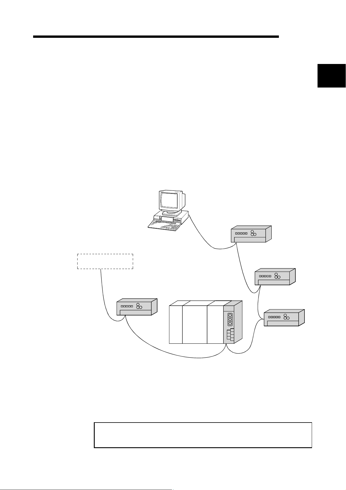
The CC-Link system connects distributed modules such as an I/O module and a
special functional module using CC-Link dedicated cables so that these modules can
be controlled by the programmable controller CPU.
(1) By distributing each module to facility equipment such as a conveyor line and a
machine device, the entire system can be connected in the most efficient manner.
(2) The on/off information of input/output and numeric data handled by modules can
easily be sent and received at high speed.
(3) A simple distributed system can be configured by connecting multiple personal
computers and programmable controller CPUs.
(4) By connecting various devices made by Mitsubishi's partner manufacturers, the
system that can provide flexible solutions to meet a wide range of user needs may
be configured.
Master station
Master/local interface board
Remote I/O station
1
Device manufactured by
a partner manufacturer
Master station The station that controls the data link system.
Remote I/O station A remote station that handles bit unit data only.
Remote device station A remote station that handles bit unit and word unit data.
Local station A station having a programmable controller CPU and the
Intelligent device station A station that can perform transient transmission.
When applying the program examples and sample programs explained in this
manual to the actual system, make sure that there is no any problem regarding
control on the target system.
Remote I/O station
Remote device station
Local station
Programmable
controller CPU
ability to communicate with the master and other local
stations.
Intelligent device station
1 - 1 1 - 1

1 OVERVIEW
1.1 Features of the CC-Link Ver.2 Board
MELSEC
1
The features of the CC-Link Ver.2 board are as follows:
(1) Personal computers can be incorporated into the CC-Link system.
Installing a CC-Link Ver.2 board into a personal computer allows the PC to be
used as a master station, standby master station, or local station compatible with
CC-Link Ver.2.
By using the CC-Link Ver.2 board as a master station, Ver.2 compatible remote
I/O stations, remote device stations, intelligent device stations and local stations
can be controlled from the PC.
(2) Programs in the CC-Link Ver.1 board can also be used in the CC-
Link Ver.2 board.
Programs developed for the CC-Link Ver.1 board can be used for the CC-Link
Ver.2 board.
(3) Parameters set for the CC-Link Ver.1 board can also be used for
the CC-Link Ver.2 board.
Parameters set for the CC-Link Ver.1 board can be reused for the CC-Link Ver.2
board. (Refer to Appendix 7)
(4) PCI/PCI ExpressRis applicable.
For Q80BD-J61BT11N, PCI is applicable.
For Q81BD-J61BT11, PCI Express
R
is applicable.
(5) Parameters can easily be set.
The parameters necessary for the operation of the CC-Link system can easily be
set with a CC-Link Ver.2 utility program; thus, programming is simplified.
(6) Test and monitoring information related to the CC-Link system can
be displayed.
The test and monitoring states in the CC-Link system can be easily displayed on
a personal computer.
(7) Support for a multiple CPU system
By specifying the logical station number via the CC-Link Ver.2 utility, a multiple
CPU system can be accessed.
(8) It provides the functions that support user programming.
It is possible to perform the remote control of remote I/O stations, remote device
stations, intelligent device stations, and local stations, as well as reading and
writing of devices using the functions that support Microsoft
Microsoft
Example:
R
Visual BasicR. Thus, user program can easily be created.
Control of the input signal X and output signal Y of a remote I/O station
Analogue voltage output control of a remote device station (analogue module)
Communication control of an intelligent device station (RS-232C module)
R
Visual C++Rand
(9) It provides the drivers for various operating systems.
Various drivers are provided for easy system configuration according to the user
environment.
For details on the compatible operating system, refer to Section 2.3.
(10) Prevent separation of cyclic data by each station
In the CC-Link Ver.2 utility, cyclic data can be assured only by enabling the
parameter of block data assurance per station setting.
1 - 2 1 - 2
1 OVERVIEW
1.2 Features of the CC-Link System
This section explains the features of the CC-Link System.
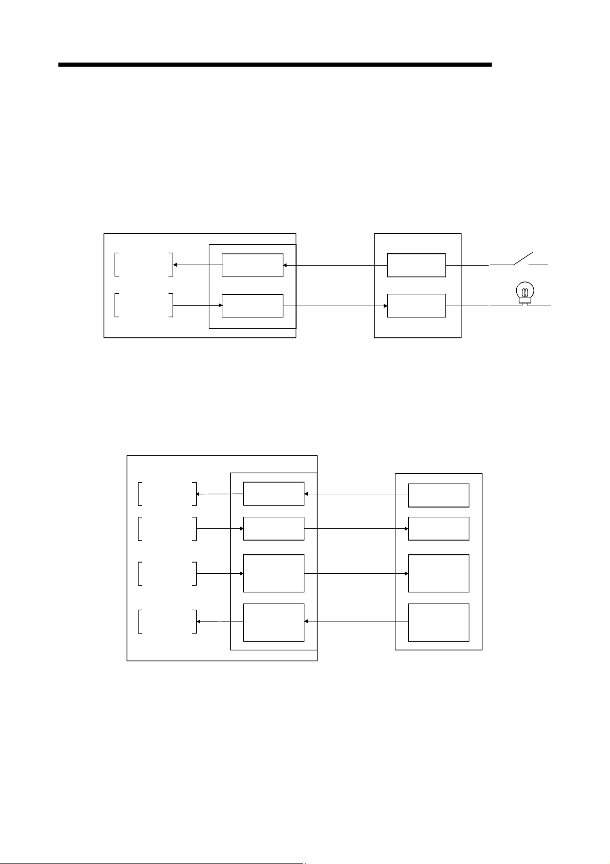
(1) Remote I/O station communication
The on/off status of a switch or indicator lamp is communicated using the remote
input RX and remote output RY.
Personal computer
Master station
Remote I/O station
MELSEC
Program
mdReceive
mdSend
Read
Write
CC-Link Ver.2 board
Remote input
RX
Remote output
RY
Link scan
Link scan
Input
Output
(2) Remote device station communication
Handshaking signals with the remote device station (initial request, error
occurred flag, etc.) are communicated using the remote input RX and remote
output RY. The setting data to the remote device station are communicated using
the remote registers RWw and RWr.
Personal computer
Program
mdReceive
mdSend
Read
Write
Master station
CC-Link Ver.2 board
Remote input
RX
Remote output
RY
Link scan
Link scan
Remote device station
Remote input
RX
Remote output
RY
mdSend
mdReceive
Write
Read
Remote
register
RWw
Remote
register
RWr
Link scan
Link scan
Remote
register
RWw
Remote
register
RWr
1 - 3 1 - 3
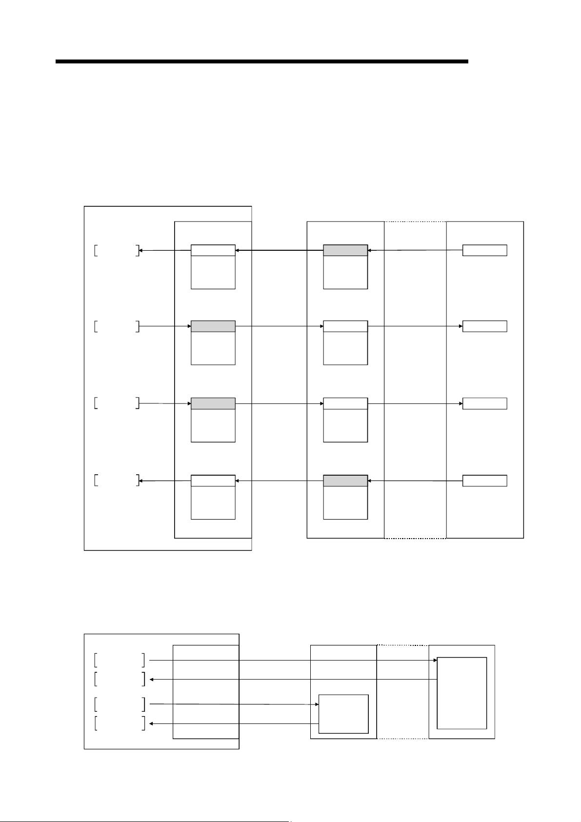
1 OVERVIEW
Personal computer
(3) Local station communication
The communication between the master station and the local station uses two
types of transmission methods: cyclic transmission and transient transmission.
(a) Cyclic transmission
Data communication between stations can be performed in N : N mode
using bit data (remote input RX and remote output RY) and word data
(remote registers RWw and RWr).
Master station
MELSEC
Program
mdReceive
mdSend
mdSend
mdReceive
Read
Write
Write
Read
CC-Link Ver.2 board
Remote input
RX
Remote output
RY
Remote
register
RWw
Remote
register
RWr
Link scan
Link scan
Link scan
Link scan
Local station
Remote output
RY
Remote input
RX
Remote
register
RWr
Remote
register
RWw
Automatic refresh
Automatic refresh
Automatic refresh
Automatic refresh
PLC CPU
Y
X
D
D
(b) Transient transmission
Read and write operations can be performed for the local station buffer
memory and CPU device at an arbitrary timing (using the mdReceive and
mdSend functions, respectively).
Personal computer
Program
mdSend
mdReceive
mdSend
mdReceive
Write
Read
Write
Read
Master station
CC-Link Ver.2 board
Transient
transmission
Transient
transmission
Transient
transmission
Transient
transmission
Local station
Buffer memory
PLC CPU
D
1 - 4 1 - 4
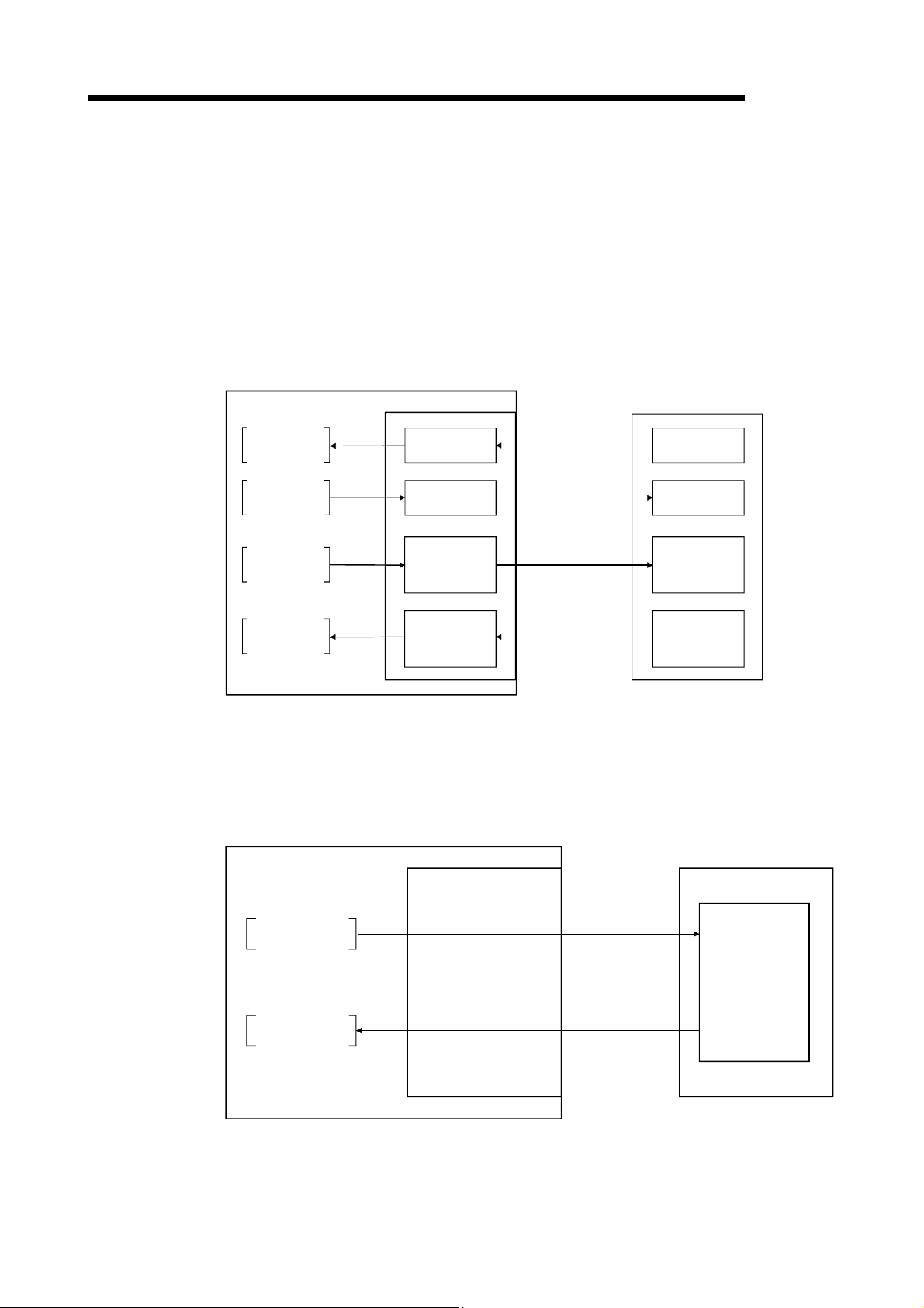
1 OVERVIEW
(4) Intelligent device station communication
The communication between the master station and the intelligent device station
uses two types of transmission methods: cyclic transmission and transient
transmission.
(a) Cyclic transmission
Handshaking signals with the intelligent device station (positioning start,
positioning end, etc.) are communicated using the remote input RX and
remote output RY. Numeric data (positioning start number, present feed
value, etc.) is communicated using the remote registers RWw and RWr.
Personal computer
Program
Master station
CC-Link Ver.2 board
MELSEC
Intelligent device station
mdReceive
mdSend
mdSend
mdReceive
Read
Write
Write
Read
Remote input
RX
Remote output
RY
Remote
register
RWw
Remote
register
RWr
Link scan
Link scan
Link scan
Link scan
Remote input
RX
Remote output
RY
Remote
register
RWw
Remote
register
RWr
(b) Transient transmission
Read and write operations can be performed for the intelligent device station
buffer memory at an arbitrary timing (using the mdReceive and mdSend
functions, respectively).
Personal computer
Program
Master station
CC-Link Ver.2 board
Intelligent device station
mdSend
mdReceive
Write
Transient
transmission
Buffer memory
Read
Transient
transmission
1 - 5 1 - 5
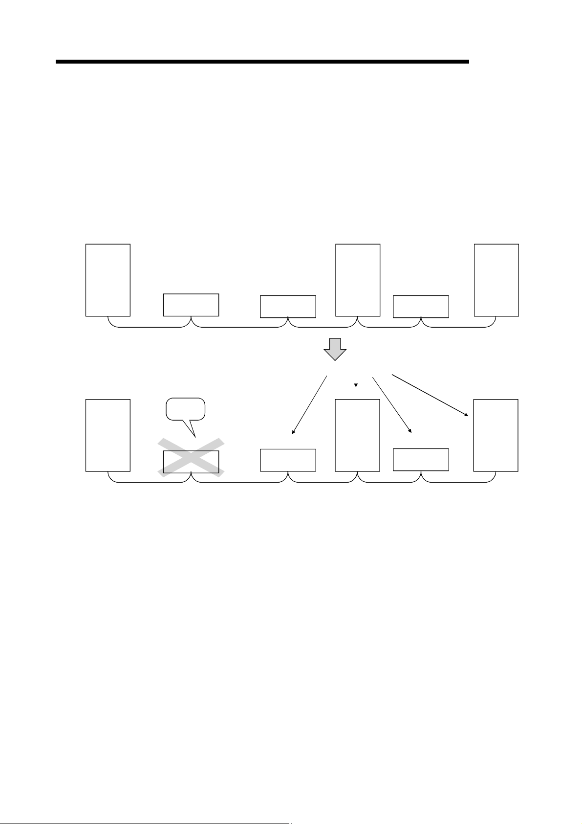
1 OVERVIEW
MELSEC
(5) System down prevention (Slave station disconnect function)
Even if a module system fails because of power failure or power off, it will not
affect the communication with other normal modules since the system employs
the bus connection method.
Also, for a module using a 2-piece terminal block, the module can be replaced
during data link. (Replace the module after turning its power off. Also check that
the switch setting on the replaced module is same as the one set on the module
before replacement.) However, if the cable is disconnected, the data link to all
stations is disabled.
Station number 4 Station number 7
Master
station
Master
station
Local station
Station number 1 Station number 3 Station number 5
Remote station
(occupying
2 stations)
Faulty
station
Station number 1 Station number 3 Station number 5
Remote station
(occupying
2 stations)
Remote station
(occupying
1 station)
Remote station
(occupying
1 station)
(occupying
1 station)
Data link continues
Station number 4
Local station
(occupying
1 station)
Remote station
(occupying
2 stations)
Remote station
(occupying
2 stations)
Local station
(occupying
4 stations)
Station number 7
Local station
(occupying
4 stations)
(6) Auto return function
When a module that has been disconnected from the link due to power off
recovers and returns to the normal status, it will join the data link automatically.
(7) Input data status setting from a data-link faulty station
The data entered (received) from a data-link faulty station can be cleared, or the
status immediately before the error can be restored.
1 - 6 1 - 6
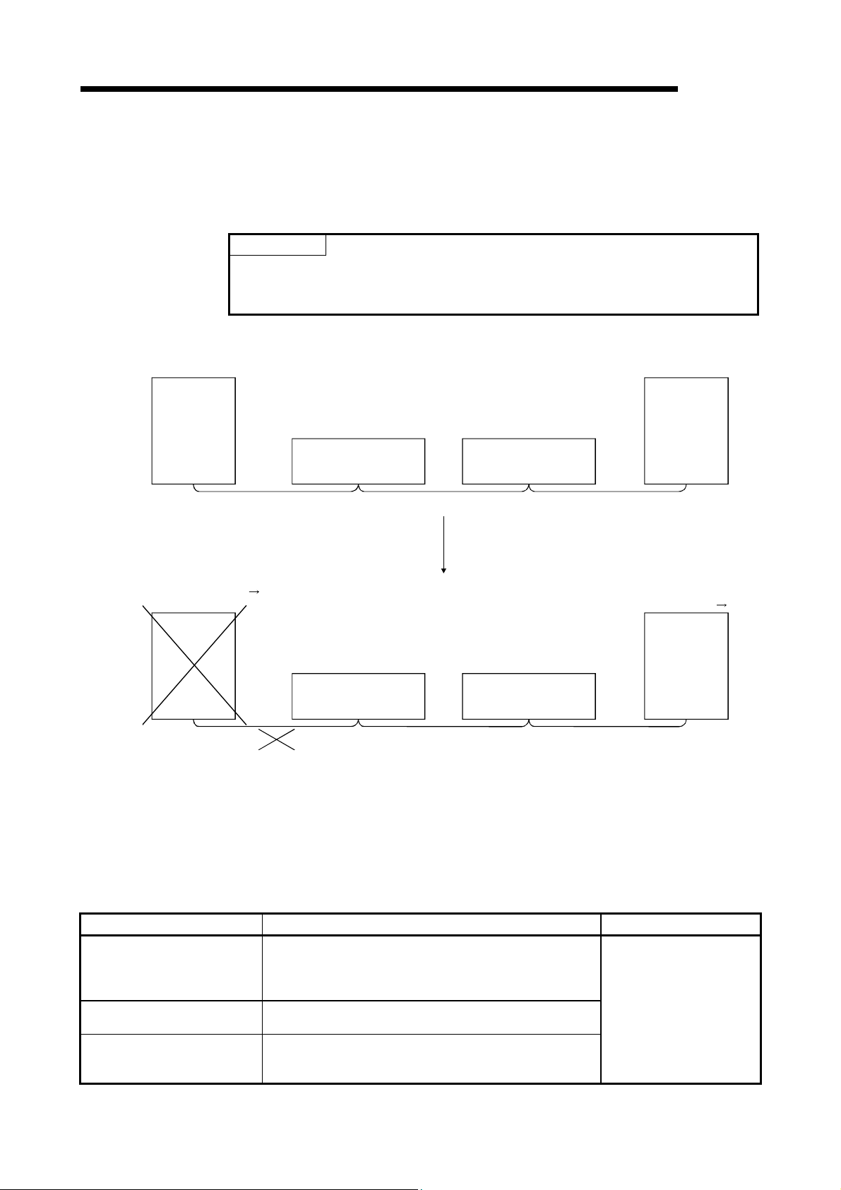
m
1 OVERVIEW
MELSEC
(8) Standby master function
This function enables the data link to continue working by switching to a standby
master station (backup station for the master station) if a malfunction occurs in
the master station.
POINT
The personal computer can be set as a standby master station only when the master
station is also a personal computer. If the master station is a programmable controller
CPU, the personal computer cannot be set as a standby master station.
Data link control
by the master station
Master station
Remote I/O station
Data link control
in progress
Cyclic communication Cyclic communication Cyclic communication
Master station is down Data link control by the standby master station
Master station
Cyclic communication Cyclic communication Cyclic communication
*1: When the master station is down and the data link control is switched to the standby master station, the station number of the
standby master station will be 0.
Station number 2
Number of occupied stations: 1
Remote I/O station
Station number 2
Number of occupied stations: 1
Remote I/O station
Station number 3
Number of occupied stations: 1
Remote I/O station
Station number 3
Number of occupied stations: 1
Standby
Station number 1
Number of occupied stations: 1
Standby
Standby master station
Station number: 1 0
Control in
Progress
(9) Mode selection according to the system
The CC-Link system has 3 types of modes applicable to various systems. Select
one of the modes on <<Parameter settings>> in the CC-Link Ver.2 utility.
Refer to Appendix 12 for the mode selection.
Mode Description Connectable station
Remote net Ver.1 mode
Remote net Ver.2 mode
Remote net additional mode
Each of the modes is described below.
The compatibility mode with the CC-Link Ver.1 board.
Select this mode when the cyclic points increasing is not
required or when the CC-Link Ver.2 board is used as
substitute for the CC-Link Ver.1 board.
Select this mode when configuring a new system with the
cyclic points increasing.
Select this mode when adding a Ver.2 compatible slave
station to the existing system to increase the number of
cyclic points.
Remote I/O station
Remote device station
Intelligent device station
Local station
Standby master station
aster station
*1
1 - 7 1 - 7

7
7
1 OVERVIEW
(10) Reserve station function
Stations that are not actually connected (stations to be connected in the future)
will not be treated as faulty stations if they are specified as reserve stations.
Stations that will be connected in the future
(Reserve station)
Station number 4
MELSEC
Master
station
Station number 1 Station number 3 Station number 8
Remote station
(occupying
2 stations)
Remote station
(occupying
1 station)
Local station
(occupying
4 stations)
Remote station
(occupying
2 stations)
(Reserve station)
Station number 10
Remote station
(occupying
1 station)
(11) Error invalid station setting function
By setting network parameters, a module that is powered off in the system
configuration will not be treated as a "data link faulty station" by the master
station and local station. However, exercise caution since errors are no longer
Master
station
detected.
Stations to be set as error invalid stations
Station number 4 Station number
Local station
Station number 1 Station number 3 Station number 5
Remote station
(occupying
2 stations)
Remote station
(occupying
1 station)
(occupying
1 station)
Remote station
(occupying
2 stations)
Local station
(occupying
4 stations)
This station does not become a data link faulty station.
Station number 4 Station number
Master
station
Station number 1 Station number 3 Station number 5
Remote station
(occupying
2 stations)
Remote station
(occupying
1 station)
Local station
(occupying
1 station)
Remote station
(occupying
2 stations)
1 - 8 1 - 8
Local station
(occupying
4 stations)
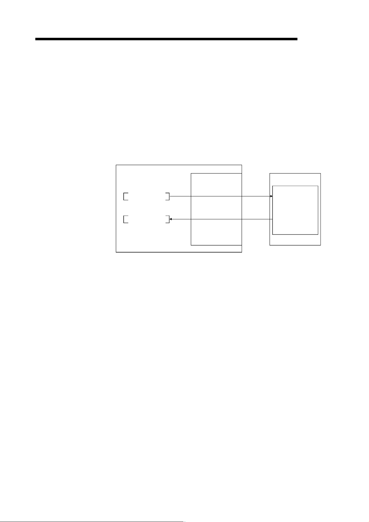
1 OVERVIEW
(12) Data link stop/restart function
The data link can be stopped and restarted while it is being used.
(13) Duplicate station number check function
This is a transmission method by which data communications are available
between 1:1stations at any given timing by specifying a target station.
(14) Transient transmission
In this method of transmission, a counterpart is specified and 1:1 communication
is performed at an arbitrary timing.
Personal computer
Program
Master station
CC-Link Ver.2 board
Local station
(1st station)
MELSEC
mdSend
mdReceive
Write
Read
Buffer memory
(15) Backward compatibility
By setting the Remote net ver.1 mode, the user program of the CC-Link Ver.1
board can be used on the CC-Link Ver.2 board.
Select the remote net ver.1 mode when the cyclic points increasing is not
required or when the CC-Link Ver.2 board is used as substitute for the CC-Link
Ver.1 board.
(16) Cyclic points increase function
When the Remote net ver.2 mode or Remote net additional mode is selected, the
number of cyclic points can be increased up to 8192 points for RX/RY and up to
2048 words for RWr/RWw per network by the expanded cyclic setting (single,
double, quadruple or octuple).
Also, it can be increased up to 224 points for RX/RY and up to 32 words for
RWr/RWw per station. (Refer to Section 4.4.7)
(17) Remote I/O station points setting
I/O points are set for remote I/O stations.
Since only the points used in remote input RX and remote output RY need to be
set for remote I/O stations, the reserved points for the remote I/O stations can be
reduced. This enables the minimum remote device allocation in the CC-Link
system. (Refer to Section 4.4.6)
1 - 9 1 - 9

1 OVERVIEW
MEMO
MELSEC
1 - 10 1 - 10

2 SYSTEM CONFIGURATION
MELSEC
2 SYSTEM CONFIGURATION
This chapter explains the system configuration of the CC-Link.
2.1 System Configuration Using CC-Link Ver.2 Board
Installed Connection Connection
Personal computer
Installed
Q80BD-J61BT11N
Q81BD-J61BT11
CC-Link
dedicated cable
CC-Link
system
2
SW0DNC-CCBD2-B
2 - 1 2 - 1

2 SYSTEM CONFIGURATION
2.2 Notes on the System Configuration
MELSEC
2
Standby master station
Master station
Q80BD-J61BT11N
Q81BD-J61BT11
A80BD-J61BT11 Ver.1 Mode
RJ61BT11*1
LJ61BT11
L26CPU-BT
L26CPU-PBT
QJ61BT11N
QJ61BT11 Ver.1 Mode
Ver.2 Mode
Additional mode
Ver.1 Mode
Ver.2 Mode
Additional mode
Ver.1 Mode
(1) Combinations of master and standby master stations
The following table shows the combination availability for the master station and
standby master station in the system configuration.
*1
RJ61BT11
Ver.2
Mode
LJ61BT11
L26CPU-BT
L26CPU-PBT
QJ61BT11N
Additional
mode
Q80BD-J61BT11N
Q81BD-J61BT11
Ver.2
Additional
Mode
mode
A80BD-J61BT11
A80BD-J61BT13
Ver.1
Mode
Ver.1 mode
Ver.1
Mode
: Available, : Not available
QJ61BT11
AJ61BT11
A1SJ61BT11
AJ61QBT11
A1SJ61QBT11
Ver.1
Mode
*1: The additional mode is not supported.
(2) Incorporating the CC-Link Ver.1 board into the CC-Link Ver.2
network system
Use any of the following software versions to utilize the CC-Link Ver.1 board at a
local station when the master station is in the remote net ver.2 mode or remote
net additional mode.
A80BDE-J61BT11: Version "R" or later
A80BDE-J61BT13: Version "Y" or later
Refer to Appendix 10 for how to check the software version.
(3) System design to prevent erroneous inputs from the remote I/O
modules
(a) When powering on and off
Start the data link after turning on the power to the remote I/O modules.
Turn off the power to the remote I/O modules after stopping the data link.
Data link start Data link stop
CC-Link Ver.2 board
(data link status)
Remote I/O module
(power status)
Executing
Stopped
ON
OFF
2 - 2 2 - 2

2 SYSTEM CONFIGURATION
(b) During momentary power failure of the remote I/O modules
When a momentary power failure occurs in the power being supplied to the
remote I/O modules (24 V DC), an erroneous input may occur.
[Cause for erroneous inputs due to a momentary power failure]
Remote I/O module
(module power supply and input
external supply power)
MELSEC
The remote I/O module hardware uses the power by internally converting
the module power (24 V DC) to 5 V DC.
When a momentary power failure occurs in a remote I/O module, the
following situation occurs:
(Time for the 5 V DC power in the remote I/O module to turn off)
> (Response time for input module on
off)
Thus, an erroneous input occurs when a refresh is performed within the
time indicated by 1) in the figure below.
1)
Remote I/O module
(internal 5 V DC)
Input (Xn)
When the input external power supply turns off, the input (Xn) turns off
after the response time for the input module changes from on to off.
REMARK
When supplying power from a single power source to multiple remote I/O modules,
select the proper type of cable and perform wiring by considering the voltage drop.
Connections can be established if the receiving port voltage at the remote I/O
module is within the specified range of the remote I/O module to be used.
Stabilized
power supply
Remote moduleRemote module
(4) Access to slave station No.64
When the CC-Link Ver.2 board is used, transient transmission to slave station
No.64 is not allowed.
REMARK
(1) Access to slave station No.64 is not possible even from GX Developer, GX
Works2 or GOT on any other station.
(2) Cyclic transmission can be normally performed with slave station No.64.
2 - 3 2 - 3

2 SYSTEM CONFIGURATION
2.3 Operating Environment
MELSEC
The following table shows the operating environment for CC-Link Ver.2 board.
Item Description
Microsoft
R
WindowsRsupported personal computer
CPU
Required
System requirements of the operating system must be met.
memory
Personal
computer
PCI bus
specifications
PCI ExpressR
bus
specifications
For Q80BD-J61BT11N
Compliant with PCI standard Rev.2.2 (5V DC, 32-bit bus, Reference clock : 33MHz)
For Q81BD-J61BT11
Compliant with PCI Express
R
standard Rev.1.0a (3.3 V DC, Link width : 1lane, Reference
clock : 100MHz)
Available hard disk space 1GB or more
Disk drive CD-ROM disk drive
Display Resolution: 800 600 dot or higher (Recommended: 1024 768 dot)
Windows 10 (Home, Pro, Enterprise, Education)
Windows 8.1, Windows 8.1 (Pro, Enterprise)
Windows Server
R
2012 R2 (Standard)
Windows 8, Windows 8 (Pro, Enterprise)
Windows Server 2012 (Standard)
Windows 7 (Home Premium, Professional, Ultimate, Enterprise)
2
Windows Server 2008 R2 (Standard, Enterprise)2
Operating system
(English version)
1
When using any of the following operating systems, use SW1DNC-CCBD2-B with the version
1.16S or earlier.
Windows Server 2008 (Standard (x86, x64), Enterprise (x86, x64))
Windows Vista
R
(Home Basic, Home Premium, Business, Ultimate, Enterprise)3
Windows Server 2003 R2 (Standard (x86, x64), Enterprise (x86, x64))
Windows XP
R
(Home Edition, Professional)3
When using any of the following operating systems, use SW1DNC-CCBD2-B with the version
1.12N or earlier.
Windows 2000 (Professional)
R
Workstation 4.0 SP3 or later
R
, Visual C++R in the following development tools
R
2015, Visual Studio 2013, Visual Studio 2012, Visual Studio 2010,
Programming language1
(English version)
Windows NT
Visual Basic
Visual Studio
Visual Studio 2008, Visual Studio 2005, Visual Studio.NET 2003,
Visual Basic 6.0, Visual C++ 6.0, Visual Basic 5.0, Visual C++ 5.0
1: For a combination of the operating system and the programming language, refer to the Microsoft Knowledge Base.
2: Apply Service Pack1 and Security Update for Windows (KB3033929). Otherwise, use SW1DNC-CCBD2-B with the
version 1.16S or earlier.
3: A 64-bit version is not supported.
POINT
For the information on how to obtain SW1DNC-CCBD2-B of the version 1.16S or
earlier, refer to Appendix 14.
2 - 4 2 - 4

2 SYSTEM CONFIGURATION
(1) Instructions for personal computer
(a) PCI standard
When a personal computer which is not compliant with the PCI or PCI
Express
failure or operation error may occur.
For details on the number of boards that can be installed, installation slot
and occupied slots, refer to Section 3.2.
(b) The functions being added
MELSEC
R
standard is used, troubles caused by failures such as a contact
Operating environment Supported version
Multiprocessor Version 1.06G or later
2 - 5 2 - 5

2 SYSTEM CONFIGURATION
(2) Instructions for operating system
(a) Supported version of SW1DNC-CCBD2-B
Windows 10
Windows 8.1, Windows Server 2012 R2
Windows 8, Windows Server 2012
Windows 7 (64-bit version),
Windows Server 2008 R2
Windows 7 (32-bit version)
Windows Server 2008 (64-bit version)
Windows Server 2008 (32-bit version)
Windows Vista
Windows Server 2003 R2 (64-bit version)
Windows Server 2003 R2 (32-bit version)
Windows XP
Windows 2000
Windows NT Workstation, Windows 98,
Windows 95
(b) User authority
Log on as a user having administrator authority.
Installation, uninstallation and usage of utilities are available only by the
administrator's authority.
(c) .NET Framework 3.5
When using one of the following operating system, .NET Framework 3.5 is
required.
• Windows 10
• Windows 8.1
• Windows Server 2012 R2
• Windows 8
• Windows Server 2012
Enable the .NET Framework 3.5 (including .NET 2.0 or 3.0) in "Turn
Windows features on or off" on the control panel.
(d) Upgrading and updating the operating system
Upgrading the operating system and updating from Windows 8 to Windows
8.1 are not supported.
Install SW1DNC-CCBD2-B by following the procedure.
1. Uninstall SW1DNC-CCBD2-B.
2. Upgrade or update the operating system.
3. Install SW1DNC-CCBD2-B with the version supporting the changed
Operating system
operating system.
MELSEC
Supported version
Q80BD-J61BT11N Q81BD-J61BT11
1.19V or later
1.15R or later
1.13P or later
1.11M or later
1.08J or later
1.11M to 1.16S
1.08J to 1.16S
1.04E to 1.16S
1.11M to 1.16S
1.06G to 1.16S
1.16S or earlier 1.06G to 1.16S
1.12N or earlier 1.06G to 1.12N
1.12N or earlier Not supported
2 - 6 2 - 6

2 SYSTEM CONFIGURATION
(e) The functions cannot be used
If an attempt is made to use any of the following functions, this product may
not operate normally.
• Activating the application with Windows
• Simplified user switch-over
• Remote desktop
• Power save mode (Hibernate, Sleep)
• Fast startup
• The language switching function set by Regional and Language Options
• Windows XP Mode
• Windows Touch or Touch
• Modern UI
• Client Hyper-V
• Server Core Installation
• Tablet mode
• Virtual desktop
In the following cases, the screen of this product may not work properly.
• The size of the text and/or other items on the screen are changed to
• The resolution of the screen is changed in operation
• The multi-display is set.
MELSEC
R
compatible mode.
values other than default values (such as 96 DPI, 100%, and 9 pt).
REMARK
• When exiting the operating system, always shut down the computer.
• For the behavior when entering the power save mode, refer to Appendix 16.
2 - 7 2 - 7

2 SYSTEM CONFIGURATION
(3) Instructions for user program
(a) Supported version of SW1DNC-CCBD2-B
(b) Language environment
User programs created in the Japanese environment work only in the
Japanese environment.
User programs created in the English environment work only in the English
environment.
(c) MELSEC data link library
For precautions when using MELSEC data link library, refer to MELSEC
Data Link Library Reference Manual.
MELSEC
User program Supported version
32-bit version user program1
64-bit version user program2
1: Programs can be created and executed on the 64-bit version operating system.
2: Programs can be created on the 32-bit version operating system, however, the
following dialog box appears and cannot be executed.
<When using Windows 7 (32-bit version)>
All versions
Version 1.11M or later
2 - 8 2 - 8

3 SPECIFICATIONS
MELSEC
3 SPECIFICATIONS
This chapter explains the specifications of CC-Link Ver.2 board.
3.1 General Specifications
The following table shows the general specifications of CC-Link Ver.2 board.
Item Specification
Operating ambient temperature 0 to 55
Storage ambient temperature -25 to 75
Operating ambient humidity
Storage ambient humidity
Frequency
5 to 8.4 Hz — 3.5 mm
Compliant with
Vibration resistance
Shock resistance
Operating atmosphere No corrosive gases
Operating altitude 1 0 to 2000 m
Installation location Inside a control panel
Overvoltage category 2
Pollution degree 3
JIS B 3502 and
IEC 61131-2
Compliant with JIS B 3502 and IEC 61131-2 (147 m/s
8.4 to 150 Hz
Frequency
5 to 8.4 Hz — 1.75 mm
8.4 to 150 Hz
1: Do not use or store the board under the environment where the atmospheric pressure is higher than the one at the
altitude of 0 m. Doing so may cause a malfunction.
2: This indicates the section of the power supply to which the equipment is assumed to be connected between the public
electrical power distribution network and the machinery within premises. Category II applies to equipment for which
electrical power is supplied from fixed facilities.
The surge voltage withstand level for up to the rated voltage of 300V is 2500V.
3: This index indicates the degree to which conductive material is generated in terms of the environment in which the
equipment is used.
Pollution degree 2 is when only non-conductive pollution occurs. A temporary conductivity caused by condensing must
be expected occasionally.
REMARK
5 to 95 % RH, non-condensing
Under Intermittent vibration
Constant
acceleration
9.8 m/s
Under Continuous vibration
Constant
acceleration
4.9 m/s
directions)
II or less
2 or less
Half amplitude Sweep count
2
Half amplitude Sweep count
2
10 times each in
—
—
2
, 3 times each in X, Y, Z
X, Y, Z
directions
—
3
General specifications both CC-Link Ver.2 board and a personal computer must be
satisfied after installation.
3 - 1 3 - 1
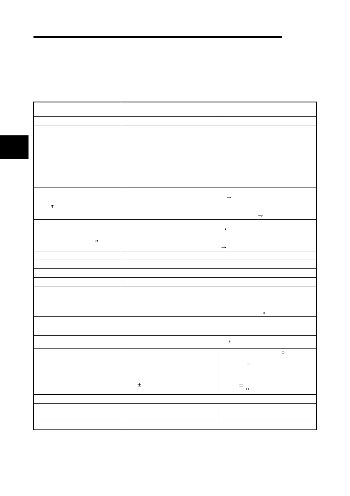
3 SPECIFICATIONS
3.2 Performance Specifications
MELSEC
Table 3.1 shows the performance specifications of the CC-Link Ver.2.
Transmission rate Can select from 156 kbps / 625 kbps / 2.5 Mbps / 5 Mbps / 10 Mbps
Overall cable distance
(maximum transmission distance)
Maximum number of connected stations
(master station)
3
Occupied station count
(when mounted to local station)
Item
Maximum number of link points per
system
1
Remote station/local station/intelligent
device station/standby master station
Number of link points per link
Communication method Broadcast polling method
Synchronous method Frame synchronous method
Encoding method NRZI method
Transmission path Bus format (conforms to EIA RS-485)
Transmission format Conforms to HDLC
Error control system CRC (X16 + X12 + X5 + 1)
1
Connection cable
RAS function
Number of boards that may be used in
one system
Loading slot PC PCI bus slot (half size)
Bus performance
Occupied slot 1 slot
5 V DC internal current consumption 0.56A —
3.3 V DC Internal current consumption — 1.06A
Weight 0.11kg 0.11kg
Table 3.1 Performance specifications
Q80BD-J61BT11N Q81BD-J61BT11
Varies according to the transmission rate (Refer to Section 3.2.2, 3.2.3)
64 (Refer to Section 3.2.1 for the conditions for the number of connected stations)
In remote net ver.1 mode:
In remote net ver.2 mode, remote net additional mode:
Remote I/O (RX, RY): 2048 points
Remote register (RWw): 256 points (master station
Remote register (RWr): 256 points (remote station/local station/ intelligent device
Remote I/O (RX, RY): 32 points (local station is 30 points)
Remote register (RWw): 4 points (master station
Remote register (RWr): 4 points (remote station/local station/intelligent device station/standby
CC-Link dedicated cable/ CC-Link dedicated high performance cable/
• Auto return function
• Slave station disconnect function
• Error detection by the link special relay/register
PCI bus
Bus width: 32 bits
Bus clock frequency: 0 to 33MHz
5V DC
PCI standard Rev.2.2
5%
1 or 4 station(s) (Can be changed on <<Parameter settings>> in the
CC-Link Ver.2 utility.)
1 to 4 station(s) (Can be changed on <<Parameter settings>> in the
CC-Link Ver.2 utility.)
device station/standby master station)
station/standby master station
device station/standby master station)
master station
Ver.1.10-compatible CC-Link dedicated cable
Specification
remote station/local station/intelligent
remote station/local station/intelligent
master station)
Maximum 4
3
X1, X2, X4, X8, X16 slot (half size)
PCI Express
Link width: 1 lane
Transmission speed: 2.5Gb/s
3.3V DC
PCI Express
9%
master station)
2
PC PCI Express
R
R
standard Rev.1.0a
R
3 - 2 3 - 2

3 SPECIFICATIONS
MELSEC
1: The link points shown above apply to the use in the remote net ver.1 mode.
Refer to Table 3.2 for those in the remote net ver.2 mode, remote additional mode.
2: Ver.1.10-compatible CC-Link dedicated cables, CC-Link dedicated cables (Ver.1.00) and CC-Link dedicated high-
performance cables cannot be used together. If used together, correct data transmission will not be guaranteed.
Also attach the terminating resister which matches the kind of the cable. (Refer to Section 5.4.1)
3: Using the CC-Link Ver.2 board and the CC-Link Ver.1 board in the same computer is not allowed.
Table 3.2 Number of link points for remote net ver.2 mode/remote net additional mode
Item Specifications
Remote I/O (RX, RY) : 8192 points
Maximum No. of link points per system
Expanded cyclic setting Single Double Quadruple Octuple
No. of link points
per station
Number of link
points per
occupied station
count
Remote I/O (RX, RY)
Remote register (RWw) 4 points 8 points 16 points 32 points
Remote register (RWr) 4 points 8 points 16 points 32 points
Occupies
1 station
Occupies
2 stations
Occupies
3 stations
Occupies
4 stations
Remote register
Remote register
Remote register
Remote register
Remote register
Remote register
Remote register
Remote register
Remote I/O
(RX, RY)
(RWw)
(RWr)
Remote I/O
(RX, RY)
(RWw)
(RWr)
Remote I/O
(RX, RY)
(RWw)
(RWr)
Remote I/O
(RX, RY)
(RWw)
(RWr)
Remote register (RWw) : 2048 points (master station
station/local station/intelligent device
station/standby master station)
Remote register (RWr) : 2048 points (remote device station/local
station/intelligent device station/standby
master station
32 points
(30 points for
local station)
32 points 32 points 64 points 128 points
4 points 8 points 16 points 32 points
4 points 8 points 16 points 32 points
64 points 96 points 192 points 384 points
8 points 16 points 32 points 64 points
8 points 16 points 32 points 64 points
96 points 160 points 320 points 640 points
12 points 24 points 48 points 96 points
12 points 24 points 48 points 96 points
128 points 224 points 448 points 896 points
16 points 32 points 64 points 128 points
16 points 32 points 64 points 128 points
32 points
(30 points for
local station)
master station)
64 points
(62 points for
local station)
remote device
128 points
(126 points for
local station)
3 - 3 3 - 3

3 SPECIFICATIONS
3.2.1 Maximum number of connected modules
A CC-Link system can be configured with the number of modules meeting the following
conditions.
Master station
Maximum 26
MELSEC
Personal
computer
+
Q80BD-J61BT11N
Q81BD-J61BT11
Terminal resistor (required)
Maximum 26 Maximum 42 Maximum 64
Intelligent device station Remote device station Remote I/O station
RS-232 interface module
AJ65BT-R2
Local station
RJ61BT11
LJ61BT11
L26CPU-BT
L26CPU-PBT
QJ61BT11(N)
Analog/digital converter
AJ65BT-64AD
Local station
A1SJ61QBT11
AJ61QBT11
CC-Link dedicated cable
Local station
A1SJ61BT11
AJ61BT11
Remote I/O module
AJ65BTB1-16D
AJ65BTC1-32D
Local station
Personal
computer
+
Q80BD-J61BT11N
Q81BD-J61BT11
A80BDE-J61BT11
A80BDE-J61BT13
Terminal resistor (required)
CC-Link dedicated cable
Total 64
(1) Remote net ver.1 mode
a: Number of modules occupying 1 station
Condition 1
Condition 2
{(1 a) + (2 b) + (3 c) + (4 d)} 64
{(16
A) + (54 B) + (88 C)} 2304
3 - 4 3 - 4
b: Number of modules occupying 2 stations
c: Number of modules occupying 3 stations
d: Number of modules occupying 4 stations
A: Number of remote I/O stations 64
B: Number of remote device stations 42
C: Number of local stations, standby master stations and
intelligent device stations 26

3 SPECIFICATIONS
(2) Remote net ver.2 mode, remote net additional mode
{(a + a2 + a4 + a8)
Condition 1
Condition 2
Condition 3
+ (b + b2 + b4 + b8) 2
+ (c + c2 + c4 + c8)
+ (d + d2 + d4 + d8) 4} 64
32) + (a2 32) + (a4 64) + (a8 128)}
[{(a
+ {(b
64) + (b2 96) + (b4 192) + (b8 384)}
+ {(c 96) + (c2 160) + (c4 320) + (c8 640)}
+ {(d 128) + (d2 224) + (d4 448) + (d8 896)}] 8192
4) + (a2 8) + (a4 16) + (a8 32)}
[{(a
+ {(b
8) + (b2 16) + (b4 + 32) + (b8 64)}
+ {(c 12) + (c2 24) + (c4 48) + (c8 96)}
+ {(d 16) + (d2 32) + (d4 64) + (d8 128)}] 2048
MELSEC
a: The total number of ver.1 compatible slave
stations that occupy 1 station, and ver.2
3
compatible slave stations that occupy 1 station
which are set to "Single".
b: The total number of ver.1 compatible slave
stations that occupy 2 stations, and ver.2
compatible slave stations that occupy 2 stations
which are set to "Single".
c: The total number of ver.1 compatible slave
stations that occupy 3 stations, and ver.2
compatible slave stations that occupy 3 stations
which are set to "Single".
d: The total number of ver.1 compatible slave
stations that occupy 4 stations, and ver.2
compatible slave stations that occupy 4 stations
which are set to "Single".
a2: The number of ver.2 compatible stations that
occupy 1 station which are set to "Double".
b2: The number of ver.2 compatible stations that
occupy 2 stations which are set to "Double".
c2: The number of ver.2 compatible stations that
occupy 3 stations which are set to "Double".
d2: The number of ver.2 compatible stations that
occupy 4 stations which are set to "Double".
a4: The number of ver.2 compatible stations that
occupy 1 station which are set to “Quadruple”.
b4: The number of ver.2 compatible stations that
occupy 2 stations which are set to "Quadruple".
c4: The number of ver.2 compatible stations that
occupy 3 stations which are set to "Quadruple".
d4: The number of ver.2 compatible stations that
occupy 4 stations which are set to "Quadruple".
a8: The number of ver.2 compatible stations that
occupy 1 station which are set to "Octuple".
b8: The number of ver.2 compatible stations that
occupy 2 stations which are set to "Octuple".
c8: The number of ver.2 compatible stations that
occupy 3 stations which are set to "Octuple".
d8: The number of ver.2 compatible stations that
occupy 4 stations which are set to "Octuple".
A: Number of remote I/O stations 64
Condition 4
{(16 A) + (54 B) + (88 C) } 2304
B: Number of remote device stations 42
C: Number of local stations, standby master
stations and intelligent device stations 26
3 - 5 3 - 5

3 SPECIFICATIONS
3.2.2 Maximum overall cable distance (for Ver.1.00)
The relationship between the transmission speed and the maximum overall cable
distance is described below:
(1) For a system consisting of only remote I/O stations and remote
device stations
MELSEC
10 Mbps
Remote I/O station
or remote
device station
Master station
2
Remote I/O station
or remote
device station
2 1 1
Maximum overall cable distance
Remote I/O station
or remote
device station
Remote I/O station
or remote
device station
1: Cable length between remote I/O stations or remote device stations.
2: Cable length between the master station and the adjacent stations.
CC-Link dedicated cable (uses terminal resistor 110 )
Transmission rate
156 kbps
625 kbps 600 m (1968.6 ft.)
2.5 Mbps 200 m (656.2 ft.)
5 Mbps
10 Mbps
30 cm (11.81 in.) or more
30 cm (11.81 in.) to
59 cm (23.23 in.)
60 cm (23.62 in.) or more 150 m (492.15 ft.)
30 cm (11.81 in.) to
59 cm (23.23 in.)
60 cm (23.62 in.) to
99 cm (38.98 in.)
1 m (3.28 ft.) or more 100 m (328.1 ft.)
Station-to-station cable length
1 2
3
1 m (3.28 ft.) or more
3
3
Maximum overall cable distance
1200 m (3937.2 ft.)
110 m (360.9 ft.)
50 m (164.1 ft.)
80 m (262.5 ft.)
CC-Link dedicated high performance cable (uses terminal resistor 130 )
Transmission rate
156 kbps
625 kbps 900 m (2952.9 ft.)
2.5 Mbps 400 m (1312.4 ft.)
5 Mbps 160 m (524.96 ft.)
Number of connected
stations: 1 to 32
Number of connected
stations: 33 to 48
Number of connected
stations: 49 to 64
30 cm (11.81 in.) or more
30 cm (11.81 in.) to
39 cm (15.35 in.)
40 cm (15.75 in.) or more 100 m (328.1 ft.)
30 cm (11.81 in.) to
39 cm (15.35 in.)
40 cm (15.75 in.) to
69 cm (27.17 in.)
70 cm (27.56 in.) or more 100 m (328.1 ft.)
3: The cable length between remote I/O stations or remote device stations is within this
range and if even one location is wired, the maximum overall cable distance will be
as indicated above.
Station-to-station cable length
1 2
3
3
3
1 m (3.28 ft.) or more
Maximum overall cable distance
1200 m (3937.2 ft.)
100 m (328.1 ft.)
80 m (262.5 ft.)
20 m (65.52 ft.)
30 m (98.43 ft.)
3 - 6 3 - 6

3 SPECIFICATIONS
First Second Third 4th 43th
Master station
Remote I/O station
MELSEC
(Example) When the transmission rate is 10 Mbps, and 43 remote I/O stations
and remote device stations are connected using the CC-Link
dedicated high performance cable, because the cable connecting the
second and third stations is "35 cm (13.78 in.)", the maximum overall
cable distance will be "80 cm (31.5 in.)".
Remote device
station
Remote I/O station Remote I/O station
Remote device
station
1 m (3.28 ft.) 50 cm (19.69 in.) 35 cm (13.78 in.) 50 cm (19.69 in.)
(2) For a system consisting of remote I/O stations, remote device
stations, local stations and intelligent device stations
Master station
Remote I/O station
or remote
device station
Remote I/O station
or remote
device station
1 222
Maximum overall cable distance
Local station
or Intelligent
device station
1: Cable length between remote I/O stations or remote device stations
2: Cable length between the master station or the local or intelligent device station and
the adjacent stations
CC-Link dedicated cable (uses terminal resistor 110 )
Transmission rate
156 kbps
625 kbps 600 m (1968.6 ft.)
2.5 Mbps 200 m (656.2 ft.)
5 Mbps 30 cm (11.81 in.) to 59 cm (23.23 in.)3 110 m (360.9 ft.)
10 Mbps
30 cm (11.81 in.) or more
60 cm (23.62 in.) or more 150 m (492.15 ft.)
30 cm (11.81 in.) to 59 cm (23.23 in.)3 50 m (164.1 ft.)
60 cm (23.62 in.) to 99 cm (38.98 in.)3 80 m (262.5 ft.)
1 m (3.28 ft.) or more 100 m (328.1 ft.)
Station-to-station cable length
1 2
2 m (6.56 ft.) or more
CC-Link dedicated high performance cable (uses terminal resistor 130 )
Transmission rate
156 kbps
625 kbps 600 m (1968.6 ft.)
2.5 Mbps 200 m (656.2 ft.)
5 Mbps
10 Mbps
30 cm (11.81 in.) or more
30 cm (11.81 in.) to 59 cm (23.23 in.)
60 cm (23.62 in.) or more 150 m (492.15 ft.)
70 cm (27.56 in.) to 99 cm (38.98 in.)
1 m (3.28 ft.) or more 80 m (262.5 ft.)
3: The cable length between remote I/O stations or remote device stations is within this
Station-to-station cable length
1 2
3
110 m (360.9 ft.)
2 m (6.56 ft.) or more
3
50 m (164.1 ft.)
range and if even one location is wired, the maximum overall cable distance will be
as indicated above.
Local station
or Intelligent
device station
Maximum overall cable distance
1200 m (3937.2 ft.)
Maximum overall cable distance
1200 m (3937.2 ft.)
3 - 7 3 - 7

3 SPECIFICATIONS
3.2.3 Maximum overall cable distance (for Ver.1.10)
The relation of the transmission speed and maximum overall cable distance when
configuring the entire system with Version 1.10 modules and cable is shown below.
MELSEC
Master station
Remote I/O station
or remote
device station
Station to station
cable length
Remote I/O station
device station
Maximum overall cable distance
Version 1.10 compatible CC-Link dedicated cable (terminal resistor of 110 used)
Transmission speed Station to station cable length Maximum overall cable distance
156kbps
625kbps 900m (2952.9 ft)
2.5Mbps 400m (1312.4 ft)
5Mbps 160m (524.96ft)
10Mbps 100m (328.1 ft)
20 cm (7.88 in) or longer
3.3 CC-Link Dedicated Cable Specifications
Use the CC-Link dedicated cable for the CC-Link system. If a cable other than the CCLink dedicated cable is used, the performance of the CC-Link system cannot be
guaranteed.
If you have any questions regarding the CC-Link dedicated cable, or if you wish to see
its specifications, refer to the CC-Link Partner Association homepage http://www.cclink.org/.
or remote
Local station or
intelligent device
station
Local station or
intelligent device
station
1200m (3937.2 ft)
REMARK
For details, refer to the CC-Link cable wiring manual issued by CC-Link Partner
Association.
3 - 8 3 - 8

3 SPECIFICATIONS
3.4 Buffer Memory List
"Buffer memory" is a memory area used for data transfer between the user program
and the CC-Link Ver.2 board.
The data of the buffer memory return to their defaults when the CC-Link Ver.2 board is
reset by powering OFF the PC or resetting the CC-Link Ver.2 Utility.
The buffer memory list is shown.
Address
Hexadecimal Decimal
0000H
to
00DF
00E0H
to
0015F
0160H
to
01DF
H
H
H
0
Use prohibited
to
223
224
Remote input (RX)
to
351
352
Remote output (RY)
to
479
1: Do not write to any area where use is prohibited. This may cause errors.
2: Used when the remote net ver.1 mode or remote net additional mode is selected.
Item Description
1
For the master station: Stores the input status
2
For the local station: Stores the input status
For the master station: Stores the output status to
For the local station: Stores the output status to
2
— — — — —
from the remote/local/
intelligent device/standby
master stations.
from the master station.
the remote/local/intelligent
device/standby master
stations.
the master station.
Also, stores the receive
data from the remote/other
local/intelligent device/
standby master stations.
Read/write
possibility
Read only
Write only
Read/write
enabled
Availability
Master
station
—
—
Local
station
: Available, — : Not available
MELSEC
Reference
—
Appendix 1
—
(1)
3 - 9 3 - 9

3 SPECIFICATIONS
Address
Hexadecimal Decimal
Remote register
(RWw)
01E0H
to
02DF
480
Master station:
to
For sending
735
H
Local station:
For sending/receiving
Remote register
(RWr)
02E0H
to
03DF
736
Master station:
to
For receiving
991
H
Local station:
For receiving
03E0H
to
05DF
05E0H
to
05FF
0600H
to
07FF
0800H
to
09FF
0A00H
to
0FFF
1000H
to
1FFF
2000H
to
2FFF
3000H
to
3FFF
992
Slave station offset and
to
size information
1503
H
1504
to
Link special relay (SB) Stores the data link status.
1535
H
1536
Link special register
to
(SW)
2047
H
2048
Use prohibited
to
2559
H
2560
to
Random access buffer
4095
H
4096
Use prohibited
to
8191
H
8192
Automatic update
to
buffer
12287
H
12288
Use prohibited
to
16383
H
1: Do not write to any area where use is prohibited. This may cause errors.
2: Used when the remote net ver.1 mode or remote net additional mode is selected.
Item Description
For the master station: Stores the send data to
the remote device/all local/
intelligent device/standby
master stations.
2
For the local station: Stores the send data to
the master/other local/
intelligent device/standby
master stations.
Also, stores the receive
data from the remote
device/other local/
intelligent device/standby
master stations.
2
For the master station: Stores the receive data
from the remote device/
local/intelligent device/
standby master stations.
For the local station: Stores the receive data
from the master station.
Stores offset and size information of
RX/RY/RWw/RWr for each remote station, local
station, intelligent device station, and standby
master station.
Stores the data link status.
1
— — — — —
The specified data is stored and used by
transient transmission.
1
— — — — —
Stores the automatic update data when
performing transient transmission with the
AJ65BT-R2 (communication using the
automatic update buffer).
1
— — — — —
Read/write
possibility
Write only
Read/write
enabled
Availability
Master
station
—
Local
station
Read only
—
Read only
Read/write
enabled
(write may
be disabled
depending
on the
device)
Read/write
enabled
Read/write
enabled
: Available, — : Not available
MELSEC
Reference
—
Appendix 1
(2)
—
Appendix 1
(2)
Appendix 1
(5)
Appendix 1
(3)
Appendix 1
(4)
Appendix 1
(6)
Appendix 1
(7)
3 - 10 3 - 10

3 SPECIFICATIONS
Address
Hexadecimal Decimal
4000H
to
41FF
4200H
to
43FF
4400H
to
4BFF
4C00H
to
53FF
16384
Ver.2 compatible
to
remote input (RX)
16895
H
16896
Ver.2 compatible
to
remote output (RY)
17407
H
Ver.2 compatible
remote register
(RWw)
17408
to
Master station:
19455
H
For sending
Local station:
For sending/receiving
Ver.2 compatible
remote register
(RWr)
19456
to
Master station:
21503
H
For receiving
Local station:
For receiving
Item Description
Read/write
possibility
For the master station: Stores the input status
from the remote/local/
3
intelligent device/standby
master stations.
Read only
For the local station: Stores the input status
from the master station.
For the master station: Stores the output status to
the remote/local/intelligent
device/standby master
Write only
stations.
For the local station: Stores the output status
3
from the master station.
Also, stores the receive
data from the remote/
other local/intelligent
Read/write
enabled
device/standby master
stations.
For the master station: Stores the send data to
the remote device/all local
/intelligent device/standby
Write only
master stations.
3
For the local station: Stores the send data to
the master/other local/
intelligent device/standby
master stations.
Also, stores the receive
data from the remote
Read/write
enabled
device/other local/
intelligent device/standby
master stations.
For the master station: Stores the receive data
from the remote device/
3
other local/intelligent
device/standby master
stations.
Read only
For the local station: Stores the receive data
from the master station.
Availability
Master
station
—
—
—
—
MELSEC
Reference
Local
station
—
Appendix 1
—
—
Appendix 1
—
(8)
(9)
5400H
to
7FFF
21504
Use prohibited
to
32767
H
1
— — — — —
: Available, — : Not available
1: Do not write to any area where use is prohibited. This may cause errors.
3: Used when the remote net ver.2 mode or remote net additional mode is selected.
3 - 11 3 - 11

3 SPECIFICATIONS
MEMO
MELSEC
3 - 12 3 - 12

4 FUNCTIONS
MELSEC
4 FUNCTIONS
4.1 Function List
Item Description Reference section
Communication with remote
I/O station
Communication with remote
device station
Communication with local
station
Communication with
intelligent device station
This chapter explains the functions of the CC-Link Ver.2 board, dividing them into four
sections: "Basic Functions," "Functions for Improving System Reliability," "Useful
Functions" and "Transient Transmission Function."
(1) Table 4.1 lists the basic functions.
Table 4.1 List of the basic functions
Performs the communication of on/off information with remote
I/O station.
Performs the communication of on/off information and
numeric data with remote device station.
Performs the communication of on/off information and
numeric data with local station.
Performs communication with intelligent device station via
cyclic transmission and transient transmission.
Section 4.2.1
Section 4.2.2
Section 4.2.3
Section 4.2.4
(2) Table 4.2 lists the functions for improving system reliability.
Table 4.2 List of the functions for improving system reliability
4
Slave station disconnect
function
Auto return function
Input data status setting
from data link faulty station
Standby master function
Driver WDT function
Station-based block data
assurance function
Item Description Reference section
Disconnects modules that cannot continue data link because
of power off, etc, and continues the data link with only the
normal modules.
When a module, which has been disconnected from data link
because of power off, etc, returns to the normal status, it
automatically joins the data link.
Sets the status (clear/latch) of the input (reception) data from
a station that became data link faulty because of power off,
etc.
Continues data link by switching to the standby master station
when a problem occurs in the master station.
Monitors the operation of the software (operating system,
driver) inside the hardware.
Prevent separation of cyclic data to new data and old data. Section 4.3.6
Section 4.3.1
Section 4.3.2
Section 4.3.3
Section 4.3.4
Section 4.3.5
4 - 1 4 - 1

4 FUNCTIONS
(3) Table 4.3 lists the useful functions.
Table 4.3 List of the useful functions
MELSEC
4
Reserved station function
Error invalid station setting
function
Data link stop/restart Stops or restarts the data link that is being executed. Section 4.4.3
Station number duplicate
check function
Multiple CPU system support
Remote I/O station point
setting
Cyclic points increase
Item Description Reference section
By assigning modules that will be connected in the future as
reserved stations, these will not be treated as data link faulty
stations.
The reserved stations can also be set as 0 points.
If any of the connected modules is designated as a reserved
station, it cannot perform data link.
Prevents modules that will be powered off in the system
configuration from being treated as data link faulty stations by
setting network parameters.
Checks for duplicate modules having the same station
number in the system.
Allows access to any CPU of a multiple CPU system via a
CC-Link Ver.2 board.
Allows the I/O points of the remote I/O stations to be selected
from among 8 points, 16 points and 32 points, reducing the
number of reserved points.
Allows the number of cyclic points per module to be increased
from 128 points for RX/RY and 16 points for RWr/RWw in the
ver.1 mode to up to 896 points for RX/RY and 128 points for
RWr/RWw in the ver.2 mode.
Section 4.4.1
Section 4.4.2
Section 4.4.4
Section 4.4.5
Section 4.4.6
Section 4.4.7
(4) Table 4.4 lists the transient transmission function.
Table 4.4 List of the transient transmission function
Transient transmission
Item Description Reference section
Designates an opposite station and communicates at an
arbitrary timing
Section 4.5.1
POINT
Refer to "Section 4.4.7 (3)(b) Whether send/receive is enabled or not" for the
availability of cyclic data communication with the CC-Link Ver.2 compatible
stations.
4 - 2 4 - 2

4 FUNCTIONS
4.2 Basic Functions
This section explains the basic functions of the CC-Link Ver.2 board.
4.2.1 Communication with remote I/O stations
The following explains an overview of the communication between the master station
and a remote I/O station. In the communication with the remote I/O station, the on/off
information of the switches and indicator lamps are communicated via the remote input
RX and remote output RY.
Personal computer Master station
CC-Link Ver.2 board
1)
Network
parameters
MELSEC
Remote I/O station
Program
mdReceive
mdSend
3)
Read Input
4)
Write
Remote input
RX
Remote output
RY
2)
Link scan
5)
Link scan
Output
[Data link startup]
1) When the personal computer is powered on, the CC-Link system starts up in
accordance with the network parameters set by the CC-Link Ver.2 utility.
4 - 3 4 - 3
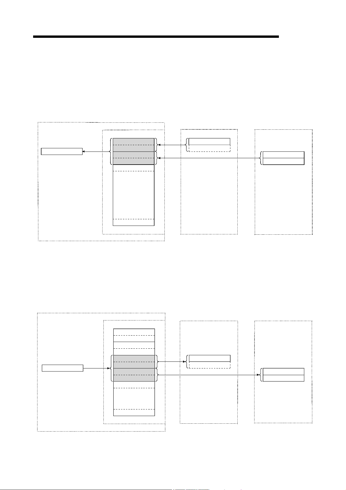
4 FUNCTIONS
Personal computer
Program
mdReceive
[Remote input]
2) The input status of each of the remote I/O stations is automatically stored (for
each link scan) in the master station's "remote input RX" buffer memory.
3) The program uses the mdReceive function to read the input status stored in
the "remote input RX" buffer memory.
Master station
CC-Link Ver.2 board
Remote input RX
3)
RX0F to RX00
RX1F to RX10
RX2F to RX20
RX3F to RX30
RX4F to RX40
2)
2)
Remote I/O station
(Station number 1:
occupies 1 station)
X0F to X00
Remote I/O station
(Station number 2:
occupies 1 station)
X0F to X00
X1F to X10
MELSEC
Personal computer
Program
mdSend
to
RX7FF to RX7F0
16-point module 32-point module
[Remote output]
4) The program uses the mdSend function to write the on/off information to the
"remote output RY" buffer memory.
5) The output status stored in the "remote output RY" buffer memory is output
automatically (for each link scan) to the remote I/O stations.
Master station
CC-Link Ver.2 board
Remote output RY
RY0F to RY00
RY1F to RY10
RY2F to RY20
RY3F to RY30
4)
RY4F to RY40
RY5F to RY50
RY6F to RY60
RY7F to RY70
RY8F to RY80
5)
5)
Remote I/O station
(Station number 3:
occupies 1 station)
Y0F to Y00
Remote I/O station
(Station number 4:
occupies 1 station)
Y0F to Y00
Y1F to Y10
to
RY7FF to RY7F0
16-point module 32-point module
4 - 4 4 - 4

4 FUNCTIONS
4.2.2 Communication with the remote device stations
This section explains an overview of the communication between the master station
and the remote device station.
In the communication with the remote device station, the handshaking signals with the
remote device station (initial data processing request flag, error reset request flag, etc.)
are communicated using the remote input RX and remote output RY. Numeric data
(averaging processing specification, digital output values, etc.) is communicated using
the remote register RWw and remote register RWr.
Personal computer
Master station
CC-Link Ver.2 board
1)
Network
parameters
MELSEC
Remote device station
Program
mdReceive
mdSend
mdSend
mdReceive
Read
Write
Write
Read
Buffer memory
Remote input
3)
Remote input RX
4)
Remote output RY
6)
9)
Remote register
RWw
Remote register
RWr
2)
Link scan
5)
Link scan
7)
Link scan
8)
Link scan
RX
Handshaking signals
such as remote READY
and initial data
processing request flag
Remote input
RY
Handshaking signals
such as error reset
request flag and initial
data processing
complete flag
Remote register
RWw
Numeric data such
as for averaging
processing setting
and A-D conversion
enable/disable setting
Remote register
RWr
Numeric data such
as digital output
values and detected
temperature value
4 - 5 4 - 5

4 FUNCTIONS
Personal computer
Program
mdReceive
[Data link startup]
1) When the personal computer is powered on, the CC-Link system starts up in
accordance with the network parameters set by the CC-Link Ver.2 utility.
[Remote input]
2) The remote input RX of each of the remote device stations is automatically
stored (for each link scan) in the master station's "remote input RX" buffer
memory.
3) The program uses the mdReceive function to read the input status stored in
the "remote input RX" buffer memory.
Remote device station
Master station
CC-Link Ver.2 board
Remote input RX
RX0F to RX00
RX1F to RX10
3)
RX2F to RX20
RX3F to RX30
RX4F to RX40
RX5F to RX50
RX6F to RX60
RX7F to RX70
RX8F to RX80
2)
2)
(Station number 1:
occupies 2 stations)
Remote input RX
Handshaking signals
such as initial data
processing request flag
RX0F to RX00
RX1F to RX10
Remote device station
(Station number 3:
occupies 2 stations)
Remote input RX
Handshaking signals
such as initial data
processing request flag
RX0F to RX00
RX1F to RX10
MELSEC
to
RX7FF to RX7F0
[Remote input RX when the AJ65BT-64DAV is set to station number 1]
Signal direction: AJ65BT-64DAV Master module
Device No. Signal name
RX00
to
RX17
RX18 Initial data processing request flag
RX19 Initial data setting complete flag
RX1A Error status flag
RX1B Remote READY
RX1C
to
RX1F
Not used
Not used
4 - 6 4 - 6

4 FUNCTIONS
Personal computer
Program
mdSend
[Remote output]
4) The program uses the mdSend function to write the on/off information to the
"remote output RX" buffer memory.
5) The remote output RY is automatically set to on/off (for each link scan)
according to the output status stored in the "remote output RY" buffer memory.
Remote device station
Master station
CC-Link Ver.2 board
Remote output RY
RY0F to RY00
RY1F to RY10
4)
RY2F to RY20
RY3F to RY30
RY4F to RY40
RY5F to RY50
RY6F to RY60
RY7F to RY70
RY8F to RY80
5)
5)
(Station number 1:
occupies 2 stations)
Remote input RY
Handshaking signals
such as error reset
request flag and initial
data processing
complete flag
RY0F to RY00
RY1F to RY10
Remote device station
(Station number 3:
occupies 2 stations)
Remote input RY
Handshaking signals
such as error reset
request flag and initial
data processing
complete flag
RY0F to RY00
RY1F to RY10
MELSEC
to
RY7FF to RY7F0
[Remote output RY when the AJ65BT-64DAV is set to station number 1]
Signal direction: Master module AJ65BT-64DAV
Device No. Signal name
RY00 CH1 analog output enable signal
RY01 CH2 analog output enable signal
RY02 CH3 analog output enable signal
RY03 CH4 analog output enable signal
RY04 Selection of offset/gain values
RY05
to
RY17
RY18 Initial data processing complete flag
RY19 Initial data setting request flag
RY1A Error reset request flag
RY1B
to
RY1F
Not used
Not used
4 - 7 4 - 7
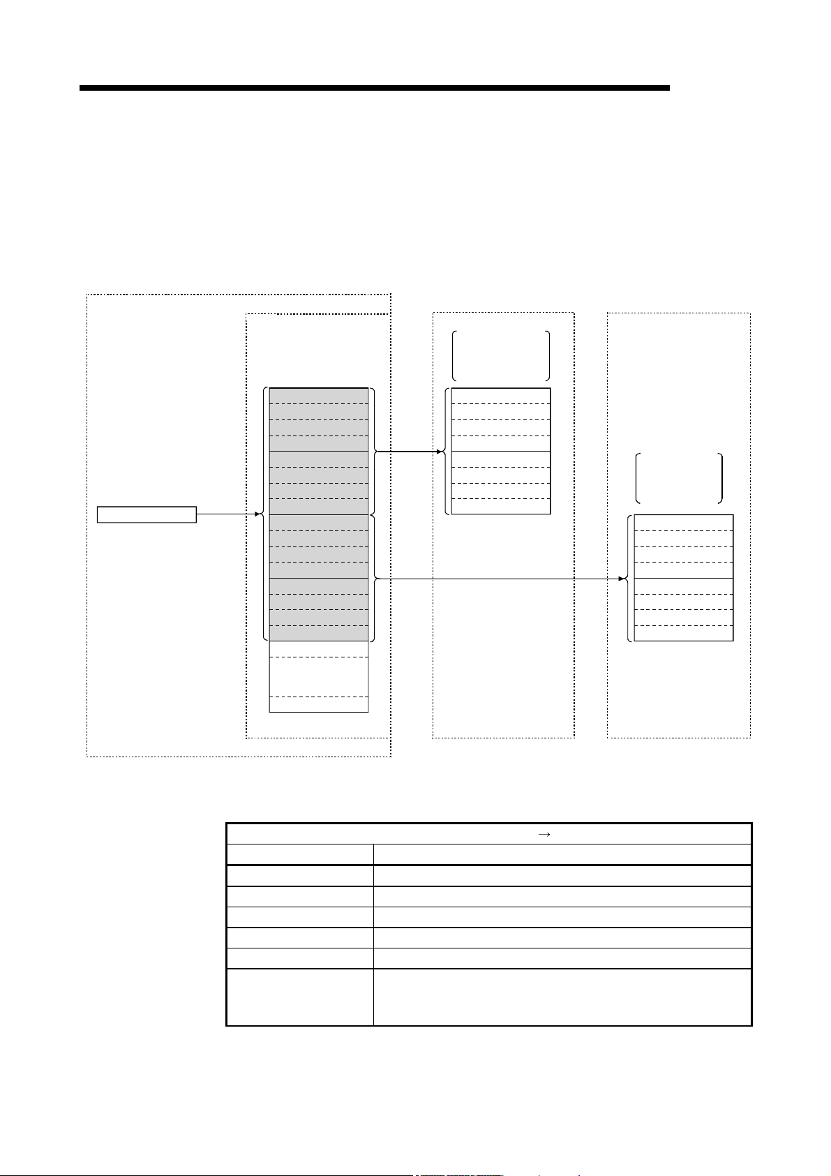
4 FUNCTIONS
Personal computer
Program
mdSend
[Writing to the remote register RWw]
6) The program uses the mdSend function to write the transmission data to the
"remote register RWw" buffer memory.
7) The data stored in the "remote register RWw" buffer memory is automatically
sent to the remote register RWw of each remote device station.
CC-Link Ver.2 board
Remote register RWw
6)
Master station
RWw0
RWw1
RWw2
RWw3
RWw4
RWw5
RWw6
RWw7
RWw8
RWw9
RWwA
RWwB
RWwC
RWwD
RWwE
RWwF
RWw10
Remote device station
(Station number 1:
occupies 2 stations)
Remote device RWw
Numerical data
such as digital
value setting areas
7)
7)
RWw0
RWw1
RWw2
RWw3
RWw4
RWw5
RWw6
RWw7
Remote device station
(Station number 3:
occupies 2 stations)
Remote device RWw
Numerical data
such \as digital
value setting
areas
MELSEC
RWw0
RWw1
RWw2
RWw3
RWw4
RWw5
RWw6
RWw7
to
RWwFF
[Remote register RWw when the AJ65BT-64DAV is
set to station number 1]
Signal direction: master module AJ65BT-64
Address Description
RWw0 CH1 digital value setting area
RWw1 CH2 digital value setting area
RWw2 CH3 digital value setting area
RWw3 CH4 digital value setting area
RWw4 Analogue output enable/disable setting area
RWw5
to
RWw7
Not used
4 - 8 4 - 8

4 FUNCTIONS
[Reading from the remote register (RWr)]
8) The remote register RWr data of each of the remote device stations is
automatically stored in the "remote register Rwr" buffer memory of the master
station.
9) The program uses the mdReceive function to read the remote register RWr
data of the remote device stations stored in the "remote register RWr" buffer
memory.
Personal computer Master station
CC-Link Ver.2 board
Remote register RWr
RWr0
RWr1
Program
mdReceive
9)
RWr2
RWr3
RWr4
RWr5
RWr6
RWr7
RWr8
RWr9
RWrA
RWrB
RWrC
RWrD
RWrE
RWrF
RWr10
Remote device station
(Station number 1:
occupies 2 stations)
Remote register RWr
Numerical data
such as set value
check codes
8)
8)
RWr0
RWr1
RWr2
RWr3
RWr4
RWr5
RWr6
RWr7
MELSEC
Remote device station
(Station number 3:
occupies 2 stations)
Remote register RWr
Numerical data
such as set value
check codes
RWr0
RWr1
RWr2
RWr3
RWr4
RWr5
RWr6
RWr7
to
RWrFF
[Remote register RWr when the AJ65BT-64DAV is
set to station number 1]
Signal direction: AJ65BT-64DAV Master module
Address Description
RWr0 CH1 set value check code
RWr1 CH2 set value check code
RWr2 CH3 set value check code
RWr3 CH4 set value check code
RWr4 Error code
RWr5
Not used RWr6
RWr7
4 - 9 4 - 9

4 FUNCTIONS
4.2.3 Communication with the local stations
The following explains an overview of the communication between the master station
and the local stations.
(1) Communication between the master station and the local stations
by cyclic transmission
The data communication between programmable controller CPUs and personal
computers can be performed in n:n mode using the remote input RX and remote
output RY (bit information used in local station systems) as well as the remote
register RWw and remote register RWr (word information for writing and reading
used in local station systems).
Personal computer Master station Local station (station number 1)
CC-Link Ve r.2 board
1)
Network
parameters
Network
parameters
Automatic refresh
parameters
MELSEC
PLC CPULocal station (station number 2)
Network
1)
parameters
Automatic refresh
parameters
Program
mdReceive
mdReceive
mdSend
mdSend
mdSend
mdSend
mdReceive
mdReceive
Read
Write
Write
Write
Write
Read
Read
Buffer memory
4)
4)
6)
6)
9)
9)
14)
14)
Remote inpu t RX
Receiveareafrom
local station No. 1
Receiveareafrom
local station No. 2
to to to
Remote output RY
Send area t o
local station No. 1
Send area t o
local station No. 2
to to to
Remote register
RWw
Send area t o
local station No. 1
Send area t o
local station No. 2
to to to
Remote register
RWr
Receiveareafrom
local station No. 1
Receiveareafrom
local station No. 2
to to to
3)
Link scanRead
3)
Link scan
7)
Link scan
7)
Link scan
10)
Link scan
10)
Link scan
13)
Link scan
13)
Link scan
Buffer memory
Remote output RY
Own station
(station number 1)
send area
Receiveareafrom
local station No. 2
Remote inpu t RX
Receiveareafrom
master station
Receiveareafrom
master station
Remote register
RWr
Receiveareafrom
master station
Receiveareafrom
master station
Remote register
RWw
Own station
(station number 1)
send area
Receiveareafrom
local station No. 2
3)
Link scan
3)
Link scan
7)
Link scan
7)
Link scan
10)
Link scan
10)
Link scan
13)
Link scan
13)
Link scan
Buffer memory
Remote output RY
Receiveareafrom
local station No. 1
Own statio n
(station number 2)
send area
Remote inpu t RX
Receiveareafrom
master station
Receiveareafrom
master station
Remote register
RWr
Receiveareafrom
master station
Receiveareafrom
master station
Remote register
RWw
Receiveareafrom
local station No. 1
Own statio n
(station number 2)
send area
5)
Automatic refresh
2)
Automatic refresh
8)
Automatic refresh
8)
Automatic refresh
11)
Automatic refresh
11)
Automatic refresh
15)
Automatic refresh
12)
Automatic refresh
Y
Y
X
X
D
D
D
D
POINT
The master station only sends data to stations where datalink has been started.
The master station does not send any data to stations where datalink has not been
started.
4 - 10 4 - 10

4 FUNCTIONS
Personal computer
Program
mdReceive
4)
MELSEC
[Data link startup]
1) When the personal computer is powered on, the CC-Link system automatically
starts up in accordance with the network parameters set by the CC-Link Ver.2
utility.
[On/off information from a local station to the master station or another
local station]
2) The on/off information of the CPU device set with automatic refresh
parameters is stored in the "remote output RY" buffer memory of a local station.
The remote output RY is used as the output information to be used by the local
station system.
3) The information in the "remote output RY" buffer memory of the local station is
automatically stored (for each link scan) in the "remote input RX" buffer
memory of the master station and the "remote output RY" buffer memory of
another local station.
4) The program uses the mdReceive function to read the input status stored in
the "remote input RX" buffer memory.
The remote input RX is used as the input information to be used by the local
station systems.
5) The input status stored in the "remote output RY" buffer memory is stored in
the CPU device set with automatic refresh parameters.
Master station
CC-Link Ver.2 board
Remote input RX
RX0F to RX00
RX1D to RX10
RX2F to RX20
RX3F to RX30
RX4F to RX40
RX5F to RX50
RX6F to RX60
RX7F to RX70
RX8F to RX80
RX9D to RX90
RXAF to RXA0
to to to
RX7FF to RX7F0
(Station number 1:
occupies 1 station)
Remote output RY
3)
3)
RY0F to RY00
RY1D to RY10
RY2F to RY20
RY3F to RY30
RY4F to RY40
RY5F to RY50
RY6F to RY60
RY7F to RY70
RY8F to RY80
RY9D to RY90
RYAF to RYA0
RY7FF to RY7F0
Local station
3)
3)
Local station
(Station number 2:
occupies 4 stations)
Remote output RY
RY0F to RY00
RY1D to RY10
RY2F to RY20
RY3F to RY30
RY4F to RY40
RY5F to RY50
RY6F to RY60
RY7F to RY70
RY8F to RY80
RY9D to RY90
RYAF to RYA0
RY7FF to RY7F0
PLC CPU
5)
2)
Y
Y
•••••••The last two bits cannot be used in the communication between the master station
and the local stations.
4 - 11 4 - 11

4 FUNCTIONS
[On/off information from the master station to the local stations]
6) The program uses the mdSend function to write the on/off information to the
"remote output RY" buffer memory of the master station.
7) The information in the "remote output RY" buffer memory is automatically
stored (for each link scan) in the "remote input RX" buffer memory of each of
the local stations.
8) The input status stored in the buffer memory "remote input RX" is stored in the
CPU device set with automatic refresh parameters.
Personal computer Master station
CC-Link Ver.2 board
Program
mdSend
6)
RY0F to RY00
RY1D to RY10
RY2F to RY20
RY3F to RY30
RY4F to RY40
RY5F to RY50
RY6F to RY60
RY7F to RY70
RY8F to RY80
RY9D to RY90
RYAF to RYA0
to to to
RY7FF to RY7F0
(Station number 1:
occupies 1 station)
Remote input RXRemote output RY
7)
7)
RX7FF to RX7F0
Local station
RX0F to RX00
RX1D to RX10
RX2F to RX20
RX3F to RX30
RX4F to RX40
RX5F to RX50
RX6F to RX60
RX7F to RX70
RX8F to RX80
RX9D to RX90
RXAF to RXA0
Local station
(Station number 2:
occupies 4 stations)
Remote input RX
7)
7)
RX0F to RX00
RX1D to RX10
RX2F to RX20
RX3F to RX30
RX4F to RX40
RX5F to RX50
RX6F to RX60
RX7F to RX70
RX8F to RX80
RX9D to RX90
RXAF to RXA0
RX7FF to RX7F0
8)
MELSEC
PLC CPU
X
•••••••The last two bits cannot be used in the communication between the master station
and the local stations.
4 - 12 4 - 12

4 FUNCTIONS
Personal computer
Program
mdSend
9)
[Word information from the master station to all local stations]
9) The program uses the mdSend function to write the word information to the
"remote register RWw" buffer memory of the master station.
The remote register RWw is used as the word information for writing to be
used by local station systems.
10) The information in the "remote register RWw" buffer memory is automatically
stored (for each link scan) in the "remote registers RWr" of all local stations.
The remote register RWr is used as the word information for reading to be
used by local station systems.
11) The word information stored in the "remote register RWr" buffer memory is
stored in the CPU device set with automatic refresh parameters.
Master station
CC-Link Ver.2 board
Remote register RWw
RWw0
RWw1
RWw2
RWw3
RWw4
RWw5
RWw6
RWw7
RWw8
RWw9
RWwA
RWwB
RWwC
RWwD
RWwE
RWwF
RWw10
RWw11
RWw12
RWw13
RWw14
Local station
(Station number 1:
occupies 1 station)
Remote register RWr
RWr0
10) 10)
10) 10)
RWr1
RWr2
RWr3
RWr4
RWr5
RWr6
RWr7
RWr8
RWr9
RWrA
RWrB
RWrC
RWrD
RWrE
RWrF
RWr10
RWr11
RWr12
RWr13
RWr14
Local station
(Station number 2:
occupies 4 stations)
Remote register RWr
RWr0
RWr1
RWr2
RWr3
RWr4
RWr5
RWr6
RWr7
RWr8
RWr9
RWrA
RWrB
RWrC
RWrD
RWrE
RWrF
RWr10
RWr11
RWr12
RWr13
RWr14
11)
MELSEC
PLC CPU
D
to to to
RWwFF
RWrFF
RWrFF
4 - 13 4 - 13

4 FUNCTIONS
Personal computer
Program
mdReceive
14)
MELSEC
[Word information from a local station to the master station and another
local station]
12) The word information set with automatic refresh parameters is stored in the
"remote register RWw" buffer memory of a local station. However, it can only
be stored in the area corresponding to the station number of the own station.
13) The information in the "remote register RWw" buffer memory is automatically
stored (for each link scan) in the "remote register RWr" of the master station
and the "remote register RWw" of another local station.
14) The program uses the mdReceive function to read the word information stored
in the "remote register RWw" buffer memory.
15) The word information stored in the "remote register RWw" buffer memory is
stored in the CPU device set with automatic refresh parameters.
Master station
CC-Link Ver.2 board
Remote register RWr
RWr0
RWr1
RWr2
RWr3
RWr4
RWr5
RWr6
RWr7
RWr8
RWr9
RWrA
RWrB
RWrC
RWrD
RWrE
RWrF
RWr10
RWr11
RWr12
RWr13
RWr14
Local station
(Station number 1:
occupies 1 station)
Remote register RWw
RWw0
13) 13)
13) 13)
RWw1
RWw2
RWw3
RWw4
RWw5
RWw6
RWw7
RWw8
RWw9
RWwA
RWwB
RWwC
RWwD
RWwE
RWwF
RWw10
RWw11
RWw12
RWw13
RWw14
Local station
(Station number 2:
occupies 4 stations)
Remote register RWw
RWw0
RWw1
RWw2
RWw3
RWw4
RWw5
RWw6
RWw7
RWw8
RWw9
RWwA
RWwB
RWwC
RWwD
RWwE
RWwF
RWw10
RWw11
RWw12
RWw13
RWw14
15)
12)
PLC CPU
D
D
to to to
RWrFF
RWwFF
RWwFF
4 - 14 4 - 14

4 FUNCTIONS
Program
(2) Communication between the master station and the local station by
transient transmission
The transient transmission is a transmission method that sends and receives
data in 1 : 1 mode by designating the opposite station at an arbitrary timing.
[When writing data to the buffer memory of the local station and the
CPU device using the mdSend function]
1) The program uses the mdSend function to write data from the master station to
the designated buffer memory of the local station and a CPU device.
2) When writing is completed, 0 is stored as return values.
Master stationPersonal computer
Local station PLC CPU
Buffer memory
mdSend
Return value
mdSend
Return value
CC-Link Ver.2 board
1)
2)
1)
2)
MELSEC
D
[When reading data from the buffer memory and CPU device in a local
Program
Value,
return value
station using the mdReceive function]
1) The program uses the mdReceive function to read data from the designated
buffer memory of the local station and the CPU device to the variables of the
program in the master station.
2) When reading is completed, 0 is stored as return values.
Master stationPersonal computer
CC-Link Ver.2 board
mdReceive
mdReceive
Value,
return value
1)
2)
1)
2)
Local station PLC CPU
D
Buffer memory
4 - 15 4 - 15

4 FUNCTIONS
4.2.4 Communication with the intelligent device station
The following explains an overview of the communication between the master station
and the intelligent device station.
(1) Communication between the master station and the intelligent
device station by cyclic transmission
Handshaking signals with the intelligent device station (positioning complete,
positioning start. etc.) are communicated using the remote input RX and remote
output RY. Numeric data (positioning start number, present feed value, etc.) is
communicated using the remote register RWw and remote register RWr.
Personal computer
Master station
CC-Link Ver.2 board
1)
Network
parameters
MELSEC
Intelligent device
station
Program
mdReceive
mdReceive
mdSend
mdSend
Read
Write
Write
Read
Buffer memory
Remote input
3)
Remote input
RX
4)
Remote output
RY
6)
Remote register
RWw
9)
Remote register
RWr
2)
Link scan
5)
Link scan
7)
Link scan
8)
Link scan
Numeric data such
as present feed value
and send speed
RX
Handshaking signals
such as initial data
processing request
and positioning
complete
Remote input
RY
Handshaking signals
such as initial data
processing complete
and positioning start
Remote register
RWw
Numeric data such
as positioning start
number and speed
change value
Remote register
RWr
4 - 16 4 - 16
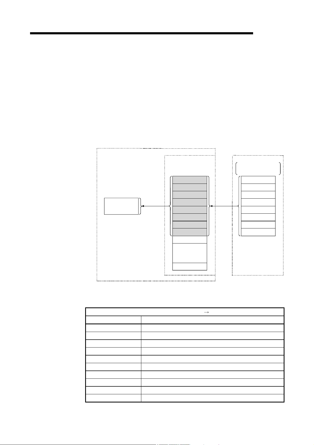
4 FUNCTIONS
MELSEC
[Data link startup]
1) When the personal computer is powered on, the CC-Link system automatically
starts up in accordance with the network parameters set by the CC-Link Ver.2
utility.
[Remote input]
2) The remote input RX of the intelligent device station is automatically stored (for
each link scan) in the "remote input RX" buffer memory of the master station.
3) The program uses the mdReceive function to read the input status stored in
the "remote input RX" buffer memory.
Personal computer Master station
CC-Link Ver.2 board
Remote input RX
Program
mdReceive
3) 2)
RX0F to RX00
RX1F to RX10
RX2F to RX20
RX3F to RX30
RX4F to RX40
RX5F to RX50
RX6F to RX60
RX7F to RX70
RX8F to RX80
Intelligent device station
(Station number 1:
occupies 4 stations)
Remote input RX
Handshaking signals
such as positioning
complete
RX0F to RX00
RX1F to RX10
RX2F to RX20
RX3F to RX30
RX4F to RX40
RX5F to RX50
RX6F to RX60
RX7F to RX70
to
RX7FF to RX7F0
[Remote input RX when the AJ65BT-D75P2-S3 is
set to station number 1]
Signal direction: AJ65BT-D75P2-S3 Master module
Device No. Signal name
RX00 D75P2 ready complete
RX01 Single-axis start complete
RX02 Dual-axes start complete
RX03 Use prohibited
RX04 Single-axis BUSY
RX05 Dual-axis BUSY
RX06 Use prohibited
RX07 Single-axis positioning complete
RX08 Dual-axis positioning complete
to to
4 - 17 4 - 17

4 FUNCTIONS
MELSEC
[Remote output]
4) The program uses the mdSend function to write the on/off information to the
"remote output RY" buffer memory.
5) The remote output RY of the intelligent device station is automatically set to
on/off (for each link scan) according to the output status stored in the "remote
output RY" buffer memory.
Personal computer Master station Intelligent device station
(Station number 1: occupies 4 stations)
Remote input RX
Handshaking signals
such as positioning
complete
RY0F to RY00
RY1F to RY10
RY2F to RY20
RY3F to RY30
RY4F to RY40
RY5F to RY50
RY6F to RY60
RY7F to RY70
Program
mdSend
CC-Link Ver.2 board
Remote input RX
RY0F to RY00
RY1F to RY10
RY2F to RY20
3) 2)
RY3F to RY30
RY4F to RY40
RY5F to RY50
RY6F to RY60
RY7F to RY70
RY8F to RY80
to
RY7FF to RY7F0
[Remote output RY when the AJ65BT-D75P2-S3 is
set to station number 1]
Signal direction: AJ65BT-D75P2-S3 Master module
Device No. Signal name
RY01 to RY0F Use prohibited
RY10 Single-axis positioning start
RY11 Dual-axis positioning start
RY12 Use prohibited
RY13 Single-axis stop
RY14 Dual-axis stop
to to
4 - 18 4 - 18

4 FUNCTIONS
MELSEC
[Writing to the remote register RWw]
6) The program uses the mdSend function to write the sending data to the
"remote register RWw" buffer memory.
7) The data stored in the "remote register RWw" buffer memory is automatically
sent to the remote register RWw of the intelligent device station.
Personal computer Master station
CC-Link Ver.2 board
Remote register RWw
RWw0
RWw1
RWw2
Program
mdSend
6) 7)
RWw3
RWw4
RWw5
RWw6
RWw7
RWw8
RWw9
RWwA
RWwB
RWwC
RWwD
RWwE
RWwF
RWw10
Intelligent device station
(Station number 1: occupies 4 stations)
Remote register RWw
Numeric data such
as positioning start
number
RWw0
RWw1
RWw2
RWw3
RWw4
RWw5
RWw6
RWw7
RWw8
RWw9
RWwA
RWwB
RWwC
RWwD
RWwE
RWwF
to
RWwFF
[Remote register RWw when the AJ65BT-D75P2-S3 is
set to station number 1]
Signal direction: Master module AJ65BT-D75P2-S3
Address Description
RWw0 Single-axis positioning start number
RWw1 Single-axis override
RWw2
RWw3
RWw4
RWw5
RWw6
RWw7
to to
Single-axis new present value
Single-axis new speed value
Single-axis JOG speed
4 - 19 4 - 19
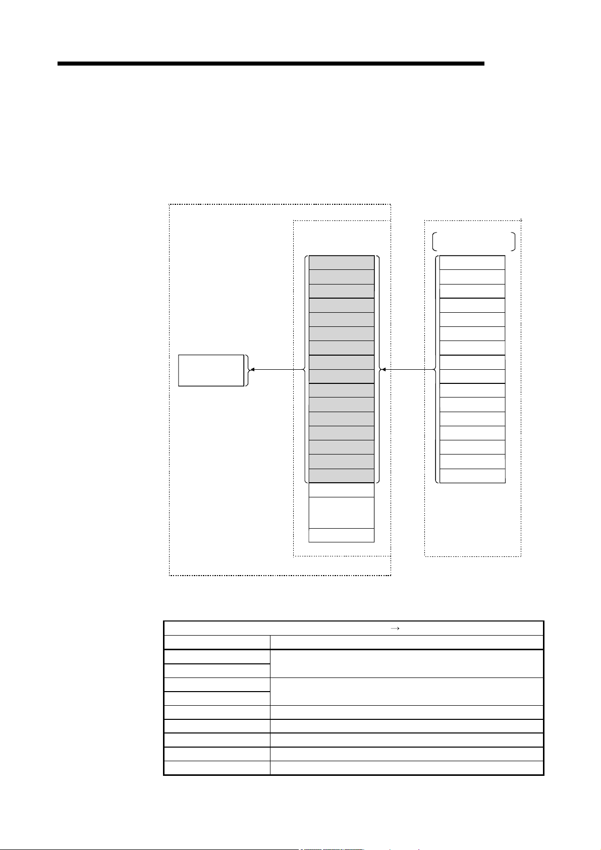
4 FUNCTIONS
MELSEC
[Reading from the remote register RWr]
8) The remote register RWr data of the intelligent device station is automatically
stored in the "remote register Rwr" buffer memory of the master station.
9) The program uses the mdReceive function to read the remote register RWr
data of the intelligent device station stored in the "remote register RWr" buffer
memory.
Personal computer
Program
mdReceive
9)
Master station
CC-Link Ver.2 board
Remote register RWr
RWr0
RWr1
RWr2
RWr3
RWr4
RWr5
RWr6
RWr7
RWr8
RWr9
RWrA
RWrB
RWrC
RWrD
RWrE
RWrF
RWr10
Intelligent device station
(Station number 1: occupies 4 stations)
Remote register RWr
Numeric data such
as present feed value
RWr0
RWr1
RWr2
RWr3
RWr4
RWr5
RWr6
8)
RWr7
RWr8
RWr9
RWrA
RWrB
RWrC
RWrD
RWrE
RWrF
to
RWrFF
[Remote register RWw when the AJ65BT-D75P2-S3 is
set to station number 1]
Signal direction: AJ65BT-D75P2-S3 Master module
Address Description
RWr0
RWr1
RWr2
RWr3
RWr4 Single-axis valid M code
RWr5 Single-axis error number
RWr6 Single-axis warning number
RWr7 Single-axis operating status
to to
4 - 20 4 - 20
Single-axis present feed value
Single-axis feed speed

4 FUNCTIONS
MELSEC
(2) Communication between the master station and the intelligent
device station by transient transmission
The transient transmission is a transmission method that sends and receives
data in 1 : 1 mode by designating an opposite station at an arbitrary timing.
[When writing data to the buffer memory of the intelligent device
station using the mdSend function]
1) The program uses the mdSend function to write data from the master station
to the designated buffer memory of the intelligent device station.
2) When writing is completed, 0 is stored as a return value.
Personal computer
Program
Master station Intelligent device station
CC-Link Ver.2 board
(1st station)
mdSend
Return value
1)
2)
Buffer memory
[When reading data from the buffer memory of the intelligent device
station using the mdReceive function]
1) The program uses the mdReceive function to read data from the designated
buffer memory of the intelligent device station to the variables of the program
in the master station.
2) When reading is completed, 0 is stored as a return value.
Personal computer
Program
mdReceive
Value, return value
1)
2)
Master station
CC-Link Ver.2 board
Intelligent device station
(1st station)
Buffer memory
4 - 21 4 - 21
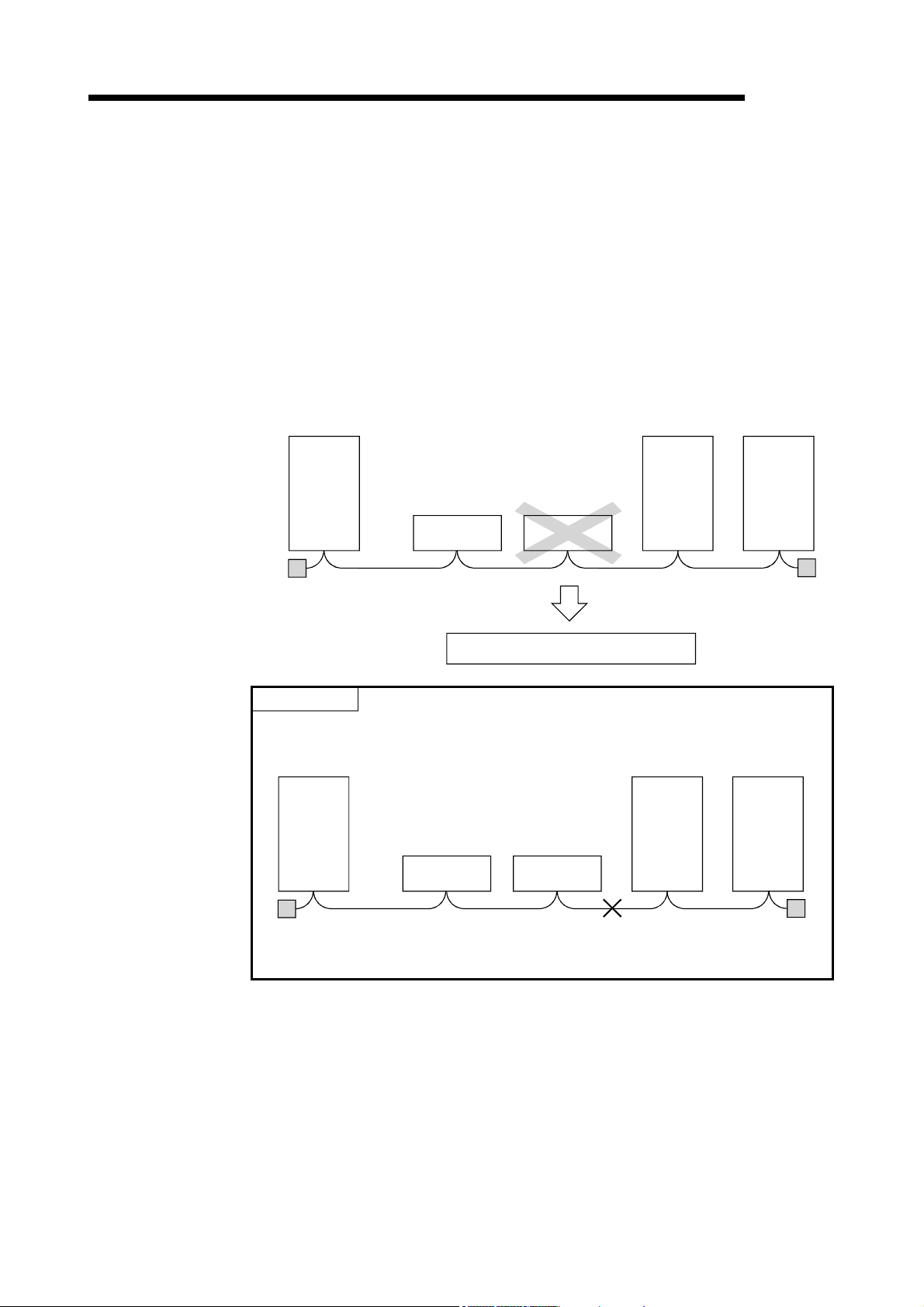
4 FUNCTIONS
MELSEC
4.3 Functions for Improving System Reliability
This section explains how to use the functions for improving the reliability of the CCLink system.
4.3.1 Disconnecting a data link faulty station and continuing the data link with only normal stations (slave station disconnect function)
This function disconnects any of the remote stations, local stations, intelligent device
stations, and standby master station if it has become data link faulty due to power off
or other cause, and continues the data link among normal remote stations, local
stations, intelligent device stations, and standby master station (no setting is required).
Master
station
Terminal
resistor
Down
Remote station
Continues data link excluding faulty station
Remote station
Local
station
Local
station
Terminal
resistor
POINT
In the event of a cable breakdown, the data link cannot be performed because
there is no terminal resistor.
Master
station
Terminal
resistor
Remote station
Remote station
Breakdown
Local
station
Local
station
Terminal
resistor
4 - 22 4 - 22

4 FUNCTIONS
MELSEC
4.3.2 Automatically reconnecting a disconnected data link faulty station when it returns to normal (auto return function)
This function allows any of the remote stations, local stations, intelligent device stations,
and standby master station that has been disconnected from the data link due to
power off or other cause to automatically reconnect to the data link when it returns to
the normal status.
[Setting method]
The setting is performed at <<Parameter settings>> in the CC-Link Ver.2 utility.
For more details on the setting, refer to Section 8.2.5.
4 - 23 4 - 23

4 FUNCTIONS
MELSEC
4.3.3 Retaining the device status of a data link faulty station (setting the input data status from a data link faulty station)
This function sets the input (reception) data status from a data link faulty station.
(1) Target input (reception) data
The following shows the target buffer memory areas.
Master station
Remote I/O station
(station number 1)
Remote device station
(station number 2)
Local station
(station number 3)
Local station
(station number 4)
Remote input (RX)
Station number 1
Station number 2
Station number 3
Station number 4
Remote ontput (RY)
Station number 1
Station number 2
Station number 3
Station number 4
Remote register
(RWw)
Station number 1
Station number 2
Station number 3
Station number 4
Remote register
(RWr)
Station number 1
Station number 2
Station number 3
Station number 4
Input
Output
Remote input (RX)
Remote output (RY)
Remote register
(RWw)
Remote register
(RWr)
Remote output (RY)
Station number 1
Station number 2
Station number 3
Station number 4
Remote input (RX)
Station number 1
Station number 2
Station number 3
Station number 4
Remote register
(RWr)
Station number 1
Station number 2
Station number 3
Station number 4
Remote register
(RWw)
Station number 1
Station number 2
Station number 3
Station number 4
•••••• Target areas for clear/latch
•••••• Areas retained regardless of the setting
The remote input RX in the master station, and the remote input RX and remote
output RY in the local stations will either clear or retain the data from faulty
stations according to the setting. The remote register RWr in the master station
and the remote registers RWw and RWr in the local stations retain data from
faulty stations regardless of the setting.
POINT
When a data link faulty station is set as an error invalid station, the input data (remote
input RX and remote output RY) from that station is retained regardless of the setting.
(2) Setting method
The setting is performed at <<Parameter settings>> in the CC-Link Ver.2 utility.
For more details on the setting, refer to Section 8.2.5.
4 - 24 4 - 24

4 FUNCTIONS
4.3.4 Continuing the data link even when the master station is faulty (standby master function)
This function enables the data link to continue by switching a faulty master station to a
standby master station (i.e. a backup station for the master station).
Note that, even if the master station has been restored, automatic switching from the
standby master station to the master station is not performed.
Data link control
by the master station
Master station
MELSEC
Standby master station
Station number 1
Number of occupied stations: 1
Remote I/O station
Data link control
in progress
Cyclic communication Cyclic communication Cyclic communication
Master station is down Data link control by the standby master station
Master station
Cyclic communication Cyclic communication Cyclic communication
Station number 2
Number of occupied stations: 1
Remote I/O station
Station number 2
Number of occupied stations: 1
In this section, the above system configuration will be used in the explanation.
POINT
Refer to "Section 2.2 (1)" for the combinations when using the CC-Link Ver.2 board
as the standby master station.
Remote I/O station
Station number 3
Number of occupied stations: 1
Remote I/O station
Station number 3
Number of occupied stations: 1
Standby
Standby master station
Station number: 1 0
Control in
Progress
4 - 25 4 - 25

4 FUNCTIONS
Master station
Remote
input RX
RX00 to RX0F
RX10 to RX1F
RX20 to RX2F
RX30 to RX3F
RX40 to RX4F
RX50 to RX5F
Remote
output RY
RY00 to RY0F
RY10 to RY1F
RY20 to RY2F
RY30 to RY3F
RY40 to RY4F
RY50 to RY5F
MELSEC
(1) Overview of link data transmission when the standby master
function is used
The following provides an overview of link data transmission when the standby
master function is used.
(a) "Master station output" while the master station is controlling the data link
Standby master station
Station number 1
Number of occupied stations: 1
Remote
input RX
RX00 to RX0F
RX10 to RX1F
RX20 to RX2F
RX30 to RX3F
RX40 to RX4F
RX50 to RX5F
Remote
output RY
RY00 to RY0F
RY10 to RY1F
RY20 to RY2F
RY30 to RY3F
RY40 to RY4F
RY50 to RY5F
Remote I/O station
Station number 2
Number of occupied stations: 1
X00 to X0F
X10 to RX1F
Y00 to Y0F
Y10 to RY1F
Remote I/O station
Station number 3
Number of occupied stations: 1
X00 to X0F
X10 to X1F
Y00 to Y0F
Y10 to Y1F
Remote
input RX
RX00 to RX0F
RX10 to RX1F
RX20 to RX2F
RX30 to RX3F
RX40 to RX4F
RX50 to RX5F
Master station
Remote
output RY
RY00 to RY0F
RY10 to RY1F
RY20 to RY2F
RY30 to RY3F
RY40 to RY4F
RY50 to RY5F
The master station data sent to the remote input RX in the standby master
station (shown by the shaded areas in the figure above) is used as the
output information when the master station becomes faulty; thus, it should be
transferred to another device using a sequence program.
In addition, when the master station becomes faulty, the transferred data is
transferred to the remote output RY of the standby master station using a
sequence program.
(b) "Master station input" while the master station is controlling the data link
Standby master station
Station number 1
Number of occupied stations: 1
Remote
input RX
RX00 to RX0F
RX10 to RX1F
RX20 to RX2F
RX30 to RX3F
RX40 to RX4F
RX50 to RX5F
Remote
output RY
RY00 to RY0F
RY10 to RY1F
RY20 to RY2F
RY30 to RY3F
RY40 to RY4F
RY50 to RY5F
Remote I/O station
Station number 2
Number of occupied stations: 1
X00 to X0F
X10 to X1F
Y00 to Y0F
Y10 to Y1F
Remote I/O station
Station number 3
Number of occupied stations: 1
X00 to X0F
X10 to X1F
Y00 to Y0F
Y10 to Y1F
The remote I/O station data sent to the remote output RY of the standby
master station is being used by the standby master station as the input
information when the standby station operates as a local station; thus, it
does not need to be transferred to another device.
4 - 26 4 - 26

4 FUNCTIONS
Master station
Remote
input RX
RX00 to RX0F
RX10 to RX1F
RX20 to RX2F
RX30 to RX3F
RX40 to RX4F
RX50 to RX5F
Remote
output RY
RY00 to RY0F
RY10 to RY1F
RY20 to RY2F
RY30 to RY3F
RY40 to RY4F
RY50 to RY5F
Master station
Remote
input RX
RX00 to RX0F
RX10 to RX1F
RX20 to RX2F
RX30 to RX3F
RX40 to RX4F
RX50 to RX5F
Remote
output RY
RY00 to RY0F
RY10 to RY1F
RY20 to RY2F
RY30 to RY3F
RY40 to RY4F
RY50 to RY5F
MELSEC
(c) "Standby master station output" when the master station is down and the
standby master station is controlling the data link
Standby master station
Station number: 1 0
Remote
input RX
RX00 to RX0F
RX10 to RX1F
RX20 to RX2F
RX30 to RX3F
RX40 to RX4F
RX50 to RX5F
Remote
output RY
RY00 to RY0F
RY10 to RY1F
RY20 to RY2F
RY30 to RY3F
RY40 to RY4F
RY50 to RY5F
Remote I/O station
Station number 2
Number of occupied stations: 1
X00toX0F
X10toX1F
Y00 to Y0F
Y10 to Y1F
Remote I/O station
Station number 3
Number of occupied stations: 1
X00 to X0F
X10 to X1F
Y00toY0F
Y10toY1F
The data sent to the remote output RY of the standby master station by a
sequence program is sent to the remote I/O stations as output information.
(d) "Standby master station input" when the master station is down and the
standby master station is controlling the data link
Standby master station
Station number: 1 0
Remote
input RX
RX00 to RX0F
RX10 to RX1F
RX20 to RX2F
RX30 to RX3F
RX40 to RX4F
RX50 to RX5F
Remote
output RY
RY00 to RY0F
RY10 to RY1F
RY20 to RY2F
RY30 to RY3F
RY40 to RY4F
RY50 to RY5F
Remote I/O station
Station number 2
Number of occupied stations: 1
X00toX0F
X10toX1F
Y00 to Y0F
Y10 to Y1F
Remote I/O station
Station number 3
Number of occupied stations: 1
X00 to X0F
X10 to X1F
Y00toY0F
Y10toY1F
The data shown in the shaded areas in the standby master station is either
input or retained according to the "Data link faulty station setting" in network
parameters.
4 - 27 4 - 27

4 FUNCTIONS
(2) Setting method
The setting is performed at <<Parameter settings>> in the CC-Link Ver.2 utility.
Refer to Section 8.2.5 for details.
(a) Setting the master station
1) Set the "Sta.No." and "Type" in <<Parameter settings>>.
Sta.No.: 0
Type: Master station
MELSEC
2) Set the "Standby master station" with the Other settings button.
Setting range: 1 to 64 (No standby master station specified for blank)
Default: 0 (No standby master station specified)
3) Select the "Ver.1 Intelligent device station" or "Ver.2 Intelligent device
station" for "Type" of the station information.
Make a selection according to the mode set in "Mode setting".
4 - 28 4 - 28

4 FUNCTIONS
MELSEC
(b) Setting the standby master station
Set the same "Standby master station number" as the one set in the master
station to "Sta. No." in <<Parameter settings>> and set "Standby master
station" for "Type".
For "Mode setting", select the same mode as the one set in "Mode setting"
of the master station.
4 - 29 4 - 29

4 FUNCTIONS
MELSEC
(3) Notes on using the standby master function
(a) Only one standby master station is allowed in a single data link system.
(b) The total number of stations can be no more than 64, including the standby
master station. The number of stations that can be occupied by the standby
master station is one or four.
(c) Do not specify station number 64 for a system in which a standby master
station exists.
If it is specified, station number 64 cannot communicate normally.
(d) If any abnormality is detected at the master station in the initial status (before
parameter communication starts), the switch to the standby master station
will not be executed.
(e) When the master station becomes faulty, the data link control will
automatically be transferred to the standby master station, but the cyclic
transmission data will not be transferred. Instructs to perform the switching
direction (SB0001 is ON) with a user program.
After switching the data link startup (SB0043) from the standby master
station to the master station is completed, the information before the
detection of abnormality at the master station will be output to each station.
Note that, a transient transmission to the master station cannot be
performed until switching the data link startup (SB0043) from the standby
master station to the master station is completed.
(If the transient transmission is performed before the switching is completed,
a timeout error will occur in the request source.)
Perform transient transmission to the master station after instructing to
perform the switching direction of the cyclic transmission data with a user
program.
(f) The master station duplex function is not available.
The control is switched from the standby master station to the master station
only once.
Therefore, if the standby master station goes down after the control has
been switched to the standby master station due to master station failure,
the CC-Link system will stop the data link. (The control will not be switched
even if the master station functions properly.)
(g) When the master station goes down and the data link control right is
switched to the standby master station, the standby master station number is
identified an error number (Corresponding bits in SB0080 or SW0080 to
SW0083 turn ON.) The station number of the standby master station is
changed to 0 from the station number set by the parameter because there is
no standby master station. The data linking is successfully performed.
Specifying a standby master station as an error invalid station prevents this
kind of error detection.
(h) When the standby master station is controlling the data link, parameters
cannot be updated.
4 - 30 4 - 30

4 FUNCTIONS
MELSEC
(i) If the terminal block of the master station is removed and then replaced in its
original position without turning the power off while the master station is
controlling the data link, both the master and standby master stations will
attempt to operate as master stations and an error will occur. (The "ERR."
LED will be flicker.)
(j) When a programmable controller is set as the master station, a CC-Link
Ver.2 board cannot be specified as a standby master station.
4 - 31 4 - 31

4 FUNCTIONS
(4) Special link relays/registers (SB and SW) related to the standby
master function
The following explains the special link relays and registers related to the standby
master function.
They are stored in the buffer memory.
(a) Special link relays (SB)
The special link relays (SB) relating to the standby master function are as
follows:
The numeric values in parentheses in the number column indicate buffer
memory addresses and bit locations.
Example: When the buffer memory address is 5E0H and the bit location is
0: (5E0H, b0)
Table 4.5 List of special link relays related to the standby master function
Number Name Description
Switches the output information from the standby master station
to the master station, and starts up the data link.
Off : Without switching direction
On : With switching direction
Shows the acknowledge status of the data link startup switching
direction from the standby master station to the master station.
Off : Not acknowledged
On : Direction acknowledged
Shows the complete status of the data link startup switching
direction from the standby master station to the master station.
Off : Not complete
On : Switching complete
Shows the data link status.
Off : Data link control by the master station
On : Data link control by the standby master station
Indicates whether or not there is a standby master station.
Off : No standby master station
On : Standby master station exists
SB0001
(5E0
H,b1)
SB0042
(5E4
H,b2)
SB0043
(5E4
H,b3)
SB0070
(5E7
H,b0)
SB0071
(5E7
H,b1)
Master station
switching and data link
startup
Acknowledge status of
master station
switching and data link
startup
Complete status of
master station
switching and data link
startup
Master station
information
Standby master
station information
(b) Special link registers (SW)
The following explains the special link registers (SW) related to the standby
master function.
The numeric values in parentheses in the number column indicate buffer
memory addresses.
Table 4.6 List of special link registers related to the standby master function
Number Name Description
The execution result of the master station switching and data
SW0043
(643
H)
SW0073
(673
H)
Result of master
station switching and
data link startup
Standby master
station number
link startup direction by the SB0001 is stored.
0 : Normal
Other than 0 : An error code is stored.
(Refer to Chapter 15.)
Stores the station number of the standby master station.
1 to 64
MELSEC
(
Applicability
Applicable, Not applicable)
Master
station
Standby master
station
Applicability
Applicable, Not applicable)
(
Master
station
Standby master
station
4 - 32 4 - 32

4 FUNCTIONS
(5) Program example when the standby master function is used
The following shows a program example when the standby master function is
void Change_StanbyMaster()
{ short Counter; // General counter
short StNo; // Station number
unsigned short DevType; // Device type
short DevNo; // Device number
short Size; // Sending data size
short RecvBuf[10]; // Buffer for receiving
unsigned short ret; // Return value
//Turn on SB1 (switching request)
StNo = 0xFF; //Set the station number
DevType = 5; //Set the device type (SB: equivalent to special M)
DevNo = 0x1; //Set the device number
ret = mdDevSet(path,StNo,DevType,DevNo);
if(ret!=0) {
printf("SBI ON processing failed, error code:%x\n",ret);
printf("Press any key\n");
getch();
mdClose(path);
exit(0);
}
for(Counter = 0;Counter < 100;Counter++){ // Confirm completion of switching
//Read SB (equivalent to special SM) 43)
Size = 2; // Set the size of sending data
StNo = 0xFF; // Set the station number
DevType = 5; // Set the device type (SB: equivalent to special M)
DevNo = 0x20; // Set the device number
ret = mdReceive(path,StNo,DevType,DevNo,&Size,&RecvBuf[0]);
if(ret!=0){
printf("mdReceive[SB43 read] processing failed, error code:%xYn";ret);
printf("Press any key\n");
getch();
mdClose(path);
exit(0);
}
if((RecvBuf[0] & 0x0800)!=0) // Exit from the loop if SB43 is on
break;
Sleep(100); // Wait for 100ms
}
// Confirm the tim e-out
if(Counter>=100){
printf("[SB43]ON conformation timed out \n");
used.
MELSEC
4 - 33 4 - 33

4 FUNCTIONS
printf("Press any key\n");
getch();
mdClose(path);
exit(0);
}
//Turn on SB1 (switching request)
StNo = 0xFF; //Set the station number
DevType = 5; //Set the device type (SB: equivalent to special M)
DevNo = 0x1; //Set the device number
ret=mdDevRst(path,StNo,DevType,DevNo);
if(ret!=0) {
printf("SBI ON processing failed, error code:%x\n",ret);
printf("Press any key\n");
getch();
mdClose(path);
exit(0);
}
// Read SW (equivalent to special SD) 43 [switching result]
Size = 2; // Set the size of sending data
StNo = 0xFF; // S et the station number
DevType = 14; // Set the device type (SD: equivalent to special D)
DevNo=43; // Set the device number
ret=mdReceive(path,StNo,DevType,DevNo,&Size,&RecvBuf[0]);
if(ret!=0){
printf("mdReceive[SW43 read] processing failed, error code:%x\n",ret);
printf("Press any key\n");
getch();
mdClose(path);
exit(0);
}
if((RecvBuf[0] & 0x0800)!=0) // Exit from the loop if SB43 is on
break;
Sleep(100); // Wait for 100ms
}
if(RecvBuf[0]!=0){ // Exit when the switching result is abnormal
printf("Failed to switch to the standby master station\n");
printf("Press any key\n)
getch();
mdClose(path);
exit(0);
}
}
POINT
Use the paths that are already obtained in other processing for the path parameters
in the standby master switching sample program. (They correspond to the path
values obtained by mdOpen.)
MELSEC
4 - 34 4 - 34

4 FUNCTIONS
MELSEC
4.3.5 Monitoring the operation of the software (operating system, driver) inside the hardware (Driver WDT function)
Driver WDT function monitors the operation of the software (operating system, driver)
inside the hardware by the timer function on CC-Link Ver.2 board.
When the driver cannot reset the timer of the board within the specified driver WDT
monitoring time, CC-Link Ver.2 board detects driver WDT error.
Driver WDT function detects driver operation delay due to the access error from the
driver to CC-Link Ver.2 board or system high load.
(1) Driver WDT settings
For the setting method, refer to section 8.2.5.
REMARK
The driver WDT function is set to invalid as a default.
(2) When the driver WDT error has occurred
The following shows the operation when driver WDT error has occurred.
1) CC-Link Ver.2 board and the driver stop link refresh and communication and
are disconnected from the network in order to avoid an erroneous output.
A CPU stop error occurs when checking the CC-Link Ver.2 board from other
station on which the driver WDT error has occurred.
2) RUN LED flicks and SD LED turns ON on the CC-Link Ver.2 board.
3) "-28158 (9202H) Driver WDT error" occurs when accessing CC-Link Ver.2
board from the application program in which the CC-Link Ver.2 utility and
MELSEC data link library function are used.
POINT
(1) When the multiple applications in which MELSEC data link library is used are
executed, driver WDT error is returned to all the programs. However, only the
CC-Link Ver.2 board in which the driver WDT error has occurred is recognized
as an error station on the network.
When using driver WDT function, set the monitoring timer considering the
margin of the personal computer load.
(2) For the troubleshooting, refer to section 16.4.2.
4 - 35 4 - 35
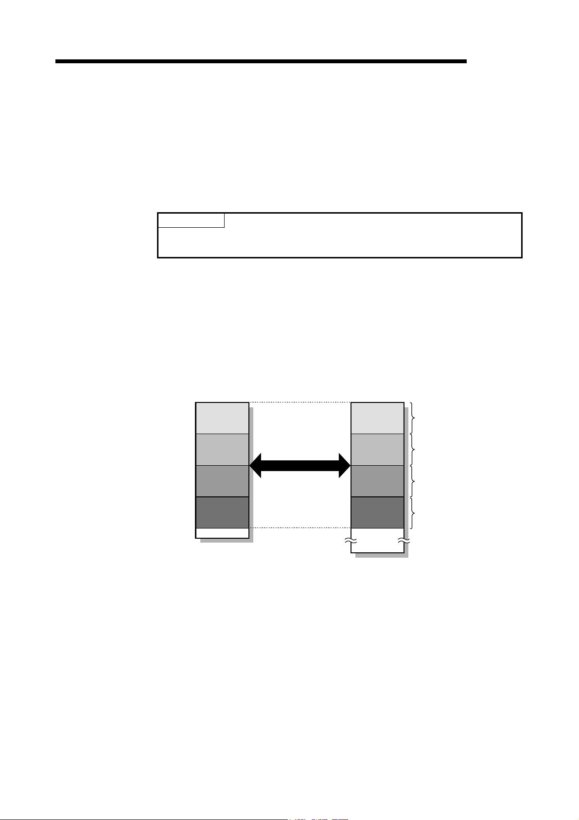
e
e
e
e
4 FUNCTIONS
4.3.6 Station-based block data assurance function
The block data assurance per station setting refers to a prevention of separating cyclic
data to new data and old data.
Cyclic data may be separated between new and old data depending on the timing of
the link refresh. This function prevents read/write data per slave station from being
separated between new and old data. Only by setting parameters in the CC-Link Ver.2
utility, it can be prevent separation of the data.
POINT
When using block data assurance per station setting, SW1DNC-CCBD2-B Version
1.17T or later and CC-Link Ver.2 board ROM version 2B or later are required.
(1) The target device of the block data assurance per station setting
The target device of the block data assurance per station setting is link device
(RX/RY/RWr/RWw).
When the block data assurance per station is enabled, the link refresh is
executed between the CC-Link Ver.2 board driver buffer (RX buffer/RY
buffer/RWr buffer/RWw buffer) and the area assigned to each station in the link
device. The area of the link device assigned to each station is the respective
slave station and data will be assured.
CC-Link Ver.2 board
driver buffer
CC-Link Ver.2 board
link device
MELSEC
Station
number 1
Station
number 2
Station
number 3
Station
number 4
Link refresh
Station
number 1
Station
number 2
Station
number 3
Station
number 4
Data
assuranc
Data
assuranc
Data
assuranc
Data
assuranc
4 - 36 4 - 36

4 FUNCTIONS
MELSEC
(2) Access method for link devices
The access method varies from the user program to the link device depending on
the setting of block data assurance per station.
(a) In the case of block data assurance per station is disabled
Accessing (reading/writing) the data from the user program is directly
carried out with respect to the link device of CC-Link Ver.2 board.
To prevent separation of the data, it is necessary to implement the data
separation prevention function in the user program.
This explains the case where personal computer transmits the data (RY0)
to programmable controller (X0) cyclically.
1) The link device RY0 of the CC-Link Ver.2 board on the sending side
(personal computer) becomes ON when the user program turns ON the
RY0.
2) By a link scan, the link device data (RY0) is stored in a link device (RX0)
of CC-Link system master/local module on the receiving side.
3) By a link refresh, the data (RX0) is stored in a device (X0) of the CPU
module.
Personal computer
1) RY0 turns O N.
Sending side (personal computer) Receiving side (programmable controller)
CC-Link Ver.2 board
RY
CC-Link
master and local
module
RX
CPU module
X
User
program
Write
Link dev ice
2)
Link scan
Link device Device
3)
Link
refresh
4 - 37 4 - 37

4 FUNCTIONS
MELSEC
(b) In the case of block data assurance per station is enabled
The data is accessed (read/write) from the user program with respect to the
CC-Link Ver.2 board driver buffer, and the data of CC-Link Ver.2 board
driver buffer and CC-Link Ver.2 board link device will be updated by a link
refresh.
When block data assurance per station setting is enabled, usually the link
refresh will be enabled. It is possible to prevent the cyclic data separation
only by setting the parameter without implementing the data separation
prevention function in the user program.
This explains the case where personal computer transmits the data (RY0)
to programmable controller (X0) cyclically.
1) The RY buffer 0 of the CC-Link Ver.2 board driver buffer on the sending
side (personal computer) becomes ON when the user program turns ON
the RY0.
2) By a link refresh, the RY buffer 0 of the CC-Link Ver.2 board driver buffer
is stored in a link device (RY0) of the CC-Link Ver.2 board.
3) By a link scan, the link device data (RY0) is stored in a link device (RX0)
of CC-Link system master/local module on the receiving side.
4) By a link refresh, the data (RX0) is stored in a device (X0) of the CPU
module.
Personal computer
1) RY0 turns ON.
Sending side (personal computer) Receiving side (programmable controller)
CC-Link
master and local
modul e
RX
CPU module
RY buffer
CC-Link Ver.2 board
RY
X
User
program
Write
CC-Link
Ver.2 board
driver buf fer
2)
Link
refresh
Link device
3)
Link scan
Link device Device
4)
Link
refresh
4 - 38 4 - 38

4 FUNCTIONS
MELSEC
(3) Link refresh
The link refresh is executed between the link device and the CC-Link Ver.2 board
driver buffer.
In order to execute the link refresh, set the block data assurance per station
setting and the link refresh cycle at <<Parameter settings>> ("Other settings"
screen) in the CC-Link Ver.2 utility. Refer to Section 8.2.5 (2).
Link refresh time is shown on "Board information" screen ("Board detail
information" screen) in the CC-Link Ver.2 utility. Refer to Section 8.2.2 (2).
However, link refresh is not executed when the board WDT error, or hardware
failure occurred, or data link has stopped.
POINT
(1) If the link refresh cycle is shortened, CPU utilization of the personal computer
may increase and load may become high.
(2) If the link refresh cycle is prolonged, the transmission delay time of the cyclic
data may increase.
(3) Depending on the following causes, the link refresh may not be executed as per
link refresh cycle set in the <<Parameter settings>> ("Other settings" screen).
Performance of a personal computer CPU is low
Too many link refresh points
Too many CC-Link Ver.2 boards has been installed
Overloading due to the other running applications
Overloading due to the other running boards
(4) When the link refresh time checked on the "Board information" screen ("Board
detail information" screen) is longer than the set link refresh cycle, take any of
the following actions.
Extend the link refresh cycle
Decrease the remote station points of the whole network
4 - 39 4 - 39

4 FUNCTIONS
MELSEC
4.4 Useful Functions
This section explains some useful functions for the CC-Link Ver.2 board.
4.4.1 Creating a program that contains modules to be added in the future (reserved station function)
This function prevents any of the remote stations, local stations, intelligent device
stations and standby master station that is not actually connected (but that will be
connected in the future) from being treated as a "data link faulty station" by the master
and local stations.
When the master station is in the Remote net ver.2 mode, the number of points for a
reserved station can be set to 0.
Station that will be connected in the future
(Reserved station)
Station number 4
Master
station
Station number 1 Station number 3 Station number 8
Remote station
(occupies
2 stations)
Remote station
(occupies
1 station)
Local station
(occupies
4 stations)
Remote station
(occupies
2 stations)
(Reserved station)
Station number 10
Remote station
(occupies
1 station)
POINT
If any of the connected remote stations, local stations, intelligent device stations or
standby master station is designated as a reserved station, the data link with that
station will become disabled.
[Setting method]
The setting is performed at <<Parameter settings>> in the CC-Link Ver.2 utility.
Refer to Section 8.2.5 for setting details.
4 - 40 4 - 40
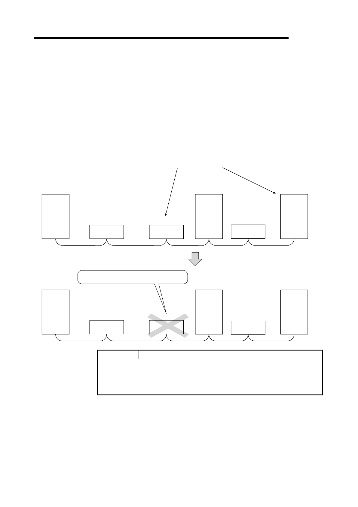
4 FUNCTIONS
MELSEC
4.4.2 Powering off a station in operation without detecting an error (error invalid station setting function)
By setting network parameter, this function prevents any of the remote stations, local
stations, intelligent device stations and standby master station that is powered off in
the system configuration from being treated as a "data link faulty station" by the master
and local stations.
Note that if a station is set as an error invalid station, problems occurring in that station
can no longer be detected.
In addition, the error invalid station settings cannot be changed while online because
they are set with network parameters.
Stations to be set as error invalid stations
Station number 4 Station number 7
Master
station
Master
station
Station number 1 Station number 3 Station number 5
Remote station
(occupies
2 stations)
This station does not become data link faulty.
Station number 1 Station number 3 Station number 5
Remote station
(occupies
2 stations)
Remote station
(occupies
1 station)
Remote station
(occupies
1 station)
Local station
(occupies
1 station)
Station number 4 Station number 7
Local station
(occupies
1 station)
Remote station
(occupies
2 stations)
Remote station
(occupies
2 stations)
Local station
(occupies
4 stations)
Local station
(occupies
4 stations)
POINT
If any of the remote stations, local stations, intelligent device stations or standby
master station that has been specified as an error invalid station is also "specified
as a reserved station," the reserved station function overrides the error invalid
station setting function.
[Setting method]
The setting is performed at <<Parameter settings>> in the CC-Link Ver.2 utility.
Refer to Section 8.2.5 for setting details.
4 - 41 4 - 41

4 FUNCTIONS
4.4.3 Checking operations for each station (data link stop/restart)
The circuit test (Hardware), circuit test (Software) and a Network test can be performed
in the CC-Link Ver.2 utility.
For more details, refer to Section 8.2.8.
4.4.4 Station number duplicate check
This function checks whether or not multiple modules with the same station number
exist in the system when the master station is started up.
1) When there is a duplicate station number, the "ERR." LED is lit, an error code
is stored in the SW006A (switch setting status), and the SB006A turns on.
2) By correcting the switch setting to normal and restarting the data link, the
"ERR." LED can be turned off and the data in the SW006A can be cleared.
MELSEC
4 - 42 4 - 42

4 FUNCTIONS
4.4.5 Multiple CPU system support
By setting the logical station number using the CC-Link Ver.2 utility, any CPU of a
multiple CPU system in which a RJ61BT11/LJ61BT11/L26CPU-BT/L26CPU-PBT/
QJ61BT11(N) is installed can be accessed by a personal computer in which a CC-Link
Ver.2 board is installed.
<Access example>
Using logical station number "65," an access can be made from a personal computer
in which a CC-Link Ver.2 board is installed to the CPU No. 4 via a QJ61BT11(N) (the
control CPU is the CPU No.2).
Master station
(CC-Link Ver.2 board)
MELSEC
Local station
Station number: 5
(CPU No.2 is
the control CPU.)
Multiple CPU system
CPU
CPU
CPU
No.4
QJ61
BT11
CPU
No.1
No.2
No.3
Terminal
resistor
[Setting the logical station number]
Set the logical station number in the "Target" of the CC-Link Ver.2 utility.
For details on the "Target", refer to Section 8.2.6.
POINT
Use a RJ61BT11/LJ61BT11/L26CPU-BT/L26CPU-PBT/QJ61BT11(N) of functional
version B or later in order to access a multiple CPU system.
A QJ61BT11(N) of functional version A cannot be used.
4 - 43 4 - 43

4 FUNCTIONS
MELSEC
4.4.6 Reducing the reserved points of the remote I/O stations (Remote I/O station points setting)
The points of each remote I/O station can be set to 8, 16 or 32 points.
Therefore, only the points used for I/O need to be allocated for the remote devices in
the CC-Link system and unused points can be reduced. It is effective for saving device
points.
The remote I/O station points setting can be used in the remote net ver.2 mode only.
Personal
computer
Program
mdSend
Remote I/O station
(Station number 2:
Occupies 1 station)
Master station
Remote output RY
Station
Station
number 2
number 1
Station number 3
Station
number 4
to
Remote I/O station
(Station number 1:
Occupies 1 station)
Y07 to Y00
8-point output module
Device area when remote I/O points setting is made
Device area when remote I/O points setting is not made
Remote I/O station
(Station number 3:
Occupies 1 station)
Y07 to Y00
Y0F to Y00
8-point output module 16-point output module 32-point output module
Remote I/O station
(Station number 4:
Occupies 1 station)
Y0F to Y00
Y1F to Y10
POINT
(1) Set points to even-numbered 8-point setting remote I/O stations consecutively.
If points are set to odd-numbered 8-point setting remote stations, select "8
points + 8 points reserved" in the "remote station points" setting of the last of
the consecutive remote I/O stations.
Master station
Remote output RY
Station
Station
number 2
number 1
Station
reserved
number 3
Station
number 4
8points+8points
(reserved)
to
Remote I/O station
(Station number 1:
Occupies 1 station)
Y07 to Y00
8-point output module
Remote I/O station
(Station number 2:
Occupies 1 station)
Y07 to Y00
8-point output module 8-point ou tput module 32-point output module
Remote I/O station
(Station number 3:
Occupies 1 station)
Y07 to Y00
Remote I/O station
(Station number 4:
Occupies 1 station)
Y0F to Y00
Y1F to Y10
Odd-numbered 8-point setting remote stations cannot be set for 8 remote
station points.
Master station
Remote output RY
Station
Station
number 2
number 1
Station
number 3
Station number 4
Cannot be set.
to
Remote I/O station
(Station number 1:
Occupies 1 station)
Y07 to Y00
8-point output mo dule
Remote I/O station
(Station number 2:
Occupies 1 station)
Y07 to Y00
8-point output mo dule 8-point o utput module 32-point output module
Remote I/O station
(Station number 3:
Occupies 1 station)
Y07 to Y00
Remote I/O station
(Station number 4:
Occupies 1 station)
Y0F to Y00
Y1F to Y10
Refer to Section 8.2.5 for parameter setting.
[Setting method]
The setting is performed at <<Parameter settings>> in the CC-Link Ver.2 utility.
Refer to Section 8.2.5 for setting details.
(1) Precautions for remote I/O station points setting
Set the points not less than I/O points of the actually installed remote I/O station
with the parameter. Otherwise, the I/O operations corresponding to the exceeded
points will not function normally.
4 - 44 4 - 44

4 FUNCTIONS
MELSEC
4.4.7 Increasing the number of cyclic points (Remote net ver.2 mode, Remote net additional mode)
This function increases the number of cyclic points in the CC-Link system.
When increasing the number of cyclic points, select one from the following two modes.
Remote net ver.2 mode ................... Mode used for configuring a new system
Remote net additional mode............ Mode used for incorporating an additional Ver.2
compatible slave station into the existing Ver.1
system
The number of cyclic points per station can be increased as indicated in the following
table.
Table 4.7
Expanded cyclic setting
Occupies 1 station
Occupies 2 stations
Occupies 3 stations
Occupies 4 stations
Remote I/O (RX, RY) 32 points 32 points 64 points 128 points
Remote register (RWw, RWr) 4 points 8 points 16 points 32 points
Remote I/O (RX, RY) 64 points 96 points 192 points 384 points
Remote register (RWw, RWr) 8 points 16 points 32 points 64 points
Remote I/O (RX, RY) 96 points 160 points 320 points 640 points
Remote register (RWw, RWr) 12 points 24 points 48 points 96 points
Remote I/O (RX, RY) 128 points 224 points 448 points 896 points
Remote register (RWw, RWr) 16 points 32 points 64 points 128 points
single double quadruple octuple
REMARK
In the remote net ver.1 mode, the number of cyclic points cannot be increased.
4 - 45 4 - 45

4 FUNCTIONS
Master station
Ver.2 mode
Ver. 2
remote
Station number 1
Station number 2
Station number 3
Station number 4
Station number 5
Station number 6
compatible
output RY
(1) Remote net ver.2 mode
This mode is designed to configure a new system.
The number of cyclic points can be increased as indicated below.
Per station, Max. RX/RY: 128 points, RWw/RWr: 32 points
(In the case of 1 station occupied with octuple setting)
Per CC-Link system, Max. RX/RY:8192 points, RWw/RWr: 2048 points
Remote I/O station
(Station number 1:
Occupies 1 station)
Output
Remote device station
Ver. 2 compatible
(Station number 2:
Occupies 1 station)
Remote output RY
Local station
Ver.2 mode
(Station number 3:
Occupies 4 stations)
Remote input RX
Station number 1
Station number 2
Station number 3
Station number 4
Station number 5
Station number 6
MELSEC
Remote device station
Ver. 2 compatible
(Station number 7:
Occupies 1 station)
Station number 7
to
quadruple
Station number 7
to
double octuple
Remote output RY
[Setting method]
The setting is performed at <<Parameter settings>> in the CC-Link Ver.2 utility.
Refer to Section 8.2.5 for setting details.
POINT
(1) In the remote net ver.2 mode, 0 points can be set for a reserved station.
(2) In the remote net ver.2 mode, RWw and RWr of the remote I/O station are set
to 0 points. Care must be taken to calculate the word points for the
programmable controller CPU side.
4 - 46 4 - 46
 Loading...