

Mitsubishi Electric SW0DNC-MNETH-B, Q80BD-J71LP21S-25, Q80BD-J71LP21G, Q80BD-J71LP21-25, Q80BD-J71BR11 User Manual
...Page 1
MELSECNET/H Interface Board
User's Manual (For SW0DNC-MNETH-B)
-Q80BD-J71LP21-25
-Q80BD-J71LP21S-25
-Q81BD-J71LP21-25
-Q80BD-J71LP21G
-Q80BD-J71BR11
Page 2

Page 3
SAFETY PRECAUTIONS
(Be sure to read these instructions before using the product.)
Before using this product, read this manual and the relevant manuals introduced in this manual carefully
and handle the product correctly with full attention to safety.
Note that these precautions apply only to this product. Refer to the user's manual of the CPU module for
safety precautions on programmable controller systems.
In this manual, the safety instructions are ranked as "
WARNING " and " CAUTION".
WARNING
CAUTION
Note that failure to observe the !CAUTION level instructions may also lead to serious results depending
on the circumstances.
Be sure to observe the instructions of both levels to ensure personal safety.
Please keep this manual in accessible place and be sure to forward it to the end user.
Indicates that incorrect handling may cause hazardous conditions,
resulting in death or severe injury.
Indicates that incorrect handling may cause hazardous conditions,
resulting in minor or moderate injury or property damage.
[Design Instructions]
!
WARNING
Make sure to see this manual for information about each station's operating status when a
communication error occurs in the network. Erroneous outputs and malfunctions may result in
serious accidents.
If a coaxial cable is disconnected, this may destabilize the line, and a data link communication
error may occur in multiple stations. Make sure to create an interlock circuit in the sequence
program so that the system will operate safely even if the above error occurs. Failure to do so
may result in a serous accident due to faulty output or malfunctions.
Provide a safety circuit outside the programmable controller so that the entire system will
operate on the safety side even when an error occurs with the personal computer.
There is a risk of an accident due to faulty output or malfunctioning.
(1) Construct circuits outside the programmable controller, including an emergency stop circuit,
protection circuit, interlock circuit for reciprocal operations such as forward and reverse, and
interlock circuit for positioning high and low limits to prevent damage to the equipment.
(2) If the station in which the board is installed is disconnected from the data link due to a data
link error, the data output from that station and written in other stations will remain the same
as immediately before the error occurred in the data link. This data will be retained until the
data link for that station is reopened (returned to system).
Provide a mechanism to monitor the status of data link and handle errors for each station
that is connected to the data link system.
A - 1 A - 1
Page 4
[Design Instructions]
!
CAUTION
Do not bunch the control wires or communication cables with the main circuit or power wires, or
install them close to each other.
They should be installed 100 mm (3.94 inch) or more from each other.
Not doing so could result in noise that would cause malfunctioning.
[Installation Instructions]
!
CAUTION
Use the board in an environment as described in the general specifications listed in this
operating manual.
If the board is used in an environment outside the ranges described in the general
specifications, it may result in an electric shock, fire, malfunctioning, damage to or deterioration
of the product.
Be sure to shut off all phases of the external power supply used by the system before installing
or removing the board. If all power is not turned off, this will result in failure of the board or
malfunctioning.
Install the board to a personal computer which is compliant with PCI standard or PCI Express
standard (Refer to "Section 2.5 Operating Environment"). Failure to do so may cause a failure or
malfunction.
Securely mount the board to the PCI slot of the mounting device.
If the board is not mounted correctly, this may lead to malfunctioning, failure or cause the board
to fall.
Insert the communication cable securely into the board connector. After it has been inserted,
check to make sure that it is not being lifted up.
A faulty connection can lead to faulty input or output.
When mounting the board, take care not to become injured by the components that are installed
or surrounding materials.
Always make sure to touch the grounded metal to discharge the electricity charged in the body,
etc., before touching the board.
Failure to do so may cause a failure or malfunctions of the board.
R
When installing the board, take care not to contact with other boards.
A - 2 A - 2
Page 5
[Wiring Instructions]
!
WARNING
Be sure to shut off all phases of the external power supply used by the system before
performing work such as installing the board and wiring.
If all power is not turned off, there is a risk of electric shock or damage to the product.
When turning on the power and operating the module after having installed the board and doing
the wiring, always attach the cover for the device module in which the board is installed.
There is a risk of electric shock if the module cover is not attached.
!
CAUTION
Properly solder the parts of a soldering-type coaxial cable connector. Incomplete soldering may
result in malfunction.
Crimp the parts of a crimping-type coaxial cable connector with proper force at a proper position.
Failure to do so may cause drop of the cable or malfunction.
For the communication cable, specialized skills and tools are required to connect the plug and
cable. The connector plug itself is a custom part.
When purchasing, consult your local Mitsubishi representative.
If the connection is incomplete, this can result in a short, fire or malfunction.
Be sure to fix communication cables connecting to the board by placing them in the duct or
clamping them.
Cables not placed in the duct or without clamping may be hang freely and accidentally pulled,
which may cause damage to the board or cable, or malfunction due to bad cable contacts.
When removing the cable from the board, do not pull the cable.
Pulling the cable that is still connected to the board may cause damage to the board or cable, or
malfunction due to bad cable contacts.
Prevent foreign matter such as chips or wiring debris from getting on the board.
Failure to do so can result in fire, breakdowns or malfunction.
Verify the rated voltage and pin assignment of the product and connect the external power
supply cable properly.
Connecting a power supply with a different voltage rating, imperfect cable crimping or faulty
wiring may cause a fire or failure.
Use a specified tool for crimping of the cable and contacting pin. Imperfect crimping may cause
malfunction.
Verify the pin assignment and fully insert the crimped contacting pin into the connector.
Imperfect insertion may cause failure or malfunction.
Insert the wired external power supply cable into the external power supply cable connector until
a click is heard. Imperfect insertion may cause failure or malfunction.
Keep the external power supply cable away from the main circuit cable, power cables and/or
load cables connected to other than programmable controllers. Ensure a distance of 100mm
(3.94 in.) between them. Failure to do so may result in malfunction due to noise, surge or
induction.
Always ground the personal computer. Failure to do so may cause malfunction.
A - 3 A - 3
Page 6
[Startup/Maintenance Instructions]
!
WARNING
Do not attach or remove the communication cable while the power supply is on.
This may result in malfunctioning.
Tighten the board fixing screws after turning off the power supply.
There is a risk of electric shock if the screws are tightened while power is on.
!
CAUTION
Thoroughly read the operating manual and carefully check to make sure everything is safe
before performing operations such as making changes to the program while the module is
operating, forced outputs, RUN, STOP and PAUSE.
Operation errors will result in damage to the equipment or accidents.
Do not dismantle or rebuild the board.
This will result in breakdowns, malfunctioning, injury or fire.
Be sure to shut off all phases of the external power supply used by the system before installing
or removing the board.
If all power is not turned off, this will result in failure of the board or malfunctioning.
The board internal microprocessor reaches very high temperatures when it is running. Do not
touch it directly when replacing the board.
This will result in breakdowns, malfunctioning or injury.
Always make sure to touch the grounded metal to discharge the electricity charged in the body,
etc., before touching the board.
Failure to do so may cause a failure or malfunctions of the board.
[Disposal Instructions]
!
CAUTION
When disposing of this product, treat it as industrial waste.
A - 4 A - 4
Page 7

CONDITIONS OF USE FOR THE PRODUCT
(1) Mitsubishi programmable controller ("the PRODUCT") shall be used in conditions;
i) where any problem, fault or failure occurring in the PRODUCT, if any, shall not lead to any major or
serious accident; and
ii) where the backup and fail-safe function are systematically or automatically provided outside of the
PRODUCT for the case of any problem, fault or failure occurring in the PRODUCT.
(2) The PRODUCT has been designed and manufactured for the purpose of being used in general
industries.
MITSUBISHI SHALL HAVE NO RESPONSIBILITY OR LIABILITY (INCLUDING, BUT NOT LIMITED
TO ANY AND ALL RESPONSIBILITY OR LIABILITY BASED ON CONTRACT, WARRANTY, TORT,
PRODUCT LIABILITY) FOR ANY INJURY OR DEATH TO PERSONS OR LOSS OR DAMAGE TO
PROPERTY CAUSED BY the PRODUCT THAT ARE OPERATED OR USED IN APPLICATION
NOT INTENDED OR EXCLUDED BY INSTRUCTIONS, PRECAUTIONS, OR WARNING
CONTAINED IN MITSUBISHI'S USER, INSTRUCTION AND/OR SAFETY MANUALS, TECHNICAL
BULLETINS AND GUIDELINES FOR the PRODUCT.
("Prohibited Application")
Prohibited Applications include, but not limited to, the use of the PRODUCT in;
Nuclear Power Plants and any other power plants operated by Power companies, and/or any other
cases in which the public could be affected if any problem or fault occurs in the PRODUCT.
Railway companies or Public service purposes, and/or any other cases in which establishment of a
special quality assurance system is required by the Purchaser or End User.
Aircraft or Aerospace, Medical applications, Train equipment, transport equipment such as Elevator
and Escalator, Incineration and Fuel devices, Vehicles, Manned transportation, Equipment for
Recreation and Amusement, and Safety devices, handling of Nuclear or Hazardous Materials or
Chemicals, Mining and Drilling, and/or other applications where there is a significant risk of injury to
the public or property.
Notwithstanding the above, restrictions Mitsubishi may in its sole discretion, authorize use of the
PRODUCT in one or more of the Prohibited Applications, provided that the usage of the PRODUCT is
limited only for the specific applications agreed to by Mitsubishi and provided further that no special
quality assurance or fail-safe, redundant or other safety features which exceed the general
specifications of the PRODUCTs are required. For details, please contact the Mitsubishi
representative in your region.
A - 5 A - 5
Page 8
REVISIONS
The manual number is given on the bottom left of the back cover.
Print Date Manual Number Revision
Nov., 2000 SH (NA)-080128-A First printing
Mar., 2001 SH (NA)-080128-B
Model addition
Q80BD-J71LP21G, Q80BD-J71LP21GE
Correction
Section 1.3, Appendix 3.1
Jun., 2001 SH (NA)-080128-C
Correction
About the Generic Terms and Abbreviations, Section 1.2, Section 1.3,
Section 2.5, Section 7.1, Section 7.1.1, Section 7.1.2, Section 7.4,
Section 8.2.3, Section 9.1.2, Section 9.2, Section 10.3.2, Section 10.4,
Appendix 3, Appendix 3.1
Addition
Section 10.8, Section 12.2, Chapter 13
Jan., 2002 SH (NA)-080128-D
Correction
Section 2.5, Section 3.1, Section 3.2, Section 5.6, Section 9.1.2,
Section 10.7, Section 12.2, Section 12.2.2
Addition
About the Generic Terms and Abbreviations, Sections 9.1.2,
Chapter 13
Dec., 2002 SH (NA)-080128-E
Correction
Safety Precautions, Section 8.2.3, Section 8.2.8, Section 8.3.3,
Section 9.1.2, Chapter 10, Section 12.2, Appendix 3.1, Appendix 4.1,
Appendix 4.2
Addition
Precautions for use, Generic Terms and Abbreviations, Section 1.2,
Section 1.3, Section 2.5, Section 5.4.2, Section 7.1.1, Section 7.1.2,
Section 7.2, Section 7.3, Section 8.1.1, Section 10.3, Chapter 13,
Section 14.3, Section 14.3.1, Section 14.5.4, Section 14.6
May, 2004 SH (NA)-080128-F
Correction
Safety Precautions, Precautions for use, Section 3.1, Section 3.2,
Section 6.3.1, Section 8.2.5, Section 8.2.10, Section 12.2, Section 12.2.1,
Section 12.2.2, Section 12.2.3, Section 12.3.3, Chapter 13,
Section 14.4.4, Section 14.7, Appendix 5.1
Addition
Generic Terms and Abbreviations, Section 1.2, Section 1.3, Section 2.4,
Section 2.5, Section 4.2.1, Section 5.2.1, Section 5.3, Section 5.4.3,
Chapter 6, Section 6.3.6, Section 8.2.1, Section 8.2.3, Section 10.3,
Section 10.3.3, Section 10.3.4, Section 10.8, Section 11.3, Chapter 12,
Section 14.4, Section 14.5.5, Section 14.6, Appendix 3
A - 6 A - 6
Page 9
The manual number is given on the bottom left of the back cover.
Print Date Manual Number Revision
Dec., 2004 SH (NA)-080128-G Chapter numbers of 5 to 14 were changed to 6 to 15 respectively.
Correction
Precautions for use, Generic Terms and Abbreviations, Chapter 1,
Section 1.1, Section 1.2, Section 1.3, Section 2.1, Section 2.4,
Section 2.5, Section 3.2, Chapter 7, Section 7.1, Section 7.2.4,
Section 9.2.2, Section 9.2.3, Section 9.2.5, Section 9.2.10,
Section 9.2.11, Section 10.1.2, Section 10.2, Section 13.2.1,
Section 15.4.3
Addition
Section 2.6, Chapter 5, Section 15.7
Jun., 2005 SH (NA)-080128-H
Model addition
Q80BD-J71LP21S-25
Correction
SAFETY PRECAUTIONS, INTRODUCTION,
Generic Terms and Abbreviations, Product List,
Section 1.2, Section 2.1, Section 2.5, Section 3.2, Section 4.1,
Section 6.1, Section 6.3, Section 6.4, Section 6.5, Section 6.6,
Section 7.2.1, Section 8.1.2, Section 9.2.2, Section 9.2.6,
Section 9.3.5, Section 11.4, Section 11.6, Section 12.3, Chapter 13,
Chapter 14, Section 15.2, Section 15.4.4, Section 15.6, Section 15.7,
Section 15.8, Appendix 4, Appendix 5
Addition
Section 6.4.4, Section 15.6, Appendix 4, Appendix 6.2
Jul.,2005 SH(NA)-080128-I
Correction
Section 2.5, Appendix 6.2
Oct.,2005 SH(NA)-080128-J
Correction
Section 2.5, Section 8.1.1, Section 8.1.2, Section 8.3, Section 9.1,
Section 15.2
Mar., 2007 SH(NA)-080128-K
Correction
Generic Terms and Abbreviations, Section 2.2.4, Section 2.5,
Section 6.4.1, Section 6.4.2, Section 8.1.1, Section 8.1.2, Section 10.1.2,
Section 10.2, Section 11.2, Section 11.6, Section 11.8, Section 15.4.5
Addition
Section 11.3.5, Section 11.3.6, Section 11.7
Oct., 2007 SH(NA)-080128-L
Correction
Generic Terms and Abbreviations, Section 1.2, Section 1.3, Section 2.5,
Chapter 5, Section 8.1.1, Section 8.3, Section 9.1, Chapter 14,
Section 15.2, Section 15.3.1
Section 8.1.2 changed to Section 8.1.3
Addition
Section 8.1.2, Appendix 5
Jan., 2008 SH(NA)-080128-M
Correction
Generic Terms and Abbreviations, Section 2.5, Section 6.5.1,
Section 6.5.2, Section 6.5.3, Section 6.6.1, Section 6.6.2, Section 8.1.1,
Section 8.1.3, Section 10.1.2, Section 10.2, Section 11.6, Section 11.7
A - 7 A - 7
Page 10
The manual number is given on the bottom left of the back cover.
Print Date Manual Number Revision
May, 2008 SH(NA)-080128-N
Model addition
Q81BD-J71LP21-25
Correction
SAFETY PRECAUTIONS, Precautions for Use, INTRODUCTION,
Generic Terms and Abbreviations, Product List, Section 1.2,
Section 1.3, Section 2.1, Section 2.5, Section 3.1, Section 3.2,
Section 6.3, Section 6.4.1, Section 6.4.3, Section 6.5.1, Section 6.5.2,
Section 6.5.3, Section 6.6.1, Section 6.6.2, Section 8.1.1, Section 8.1.3,
Section 8.2, Section 8.3, Section 9.1, Section 9.1.1, Section 9.2.2,
Section 9.2.6, Section 10.1.2, Section 11.3, Section 15.2, Section 15.3,
Section 15.4.4
Appendix 3 to 6 changed to Appendix 2 to 5
Addition
Appendix 5.4
Deletion
Appendix 2, Appendix 2.1
Jun., 2008 SH(NA)-080128-O
Correction
Section 1.3, Section 2.5, Section 9.2.4, Section 15.4.4,
Appendix 4.2
Oct., 2008 SH(NA)-080128-P
Jul., 2009 SH(NA)-080128-Q
Oct., 2009 SH(NA)-080128-R
Dec., 2010 SH(NA)-080128-T
Mar., 2011 SH(NA)-080128-U
May, 2011 SH(NA)-080128-V
Addition
Generic Terms and Abbreviations, Section 2.5, Section 10.1.2
Addition
Product List, Chapter 5, Appendix 4.1
Addition
Section 8.1.3, Section 11.4, Section 13.3.4, Section 15.2
Correction
SAFETY PRECAUTIONS, Section 2.6, Section 4.1, Section 11.6,
Section 11.7, Section 12.1.1, Section 13, Section 13.1, Section 14
Correction
Section 2.5
Addition
Appendix 2
Correction
Product List, Chapter 7, Section 9.2.2, Section 15.2, Appendix 1,
Appendix 5.2
Appendix 3 to 6 changed to Appendix 4 to 7
Correction
Precautions for Use, Chapter 8
Deletion
Section 8.3
A - 8 A - 8
Page 11
The manual number is given on the bottom left of the back cover.
Print Date Manual Number Revision
Sep., 2011 SH(NA)-080128-W
Correction
SAFETY PRECAUTIONS, INTRODUCTION, Manuals,
How to Use This Manual, Generic Terms and Abbreviations,
Product List, Section 1.2, Section 2.1, Section 2.5, Section 3.1,
Section 3.2, Section 5.1.1, Section 6.2.1, Chapter 7, Section 8.1,
Section 8.1.1, Section 8.1.2, Section 8.1.3, Section 8.2, Section 9.1.1,
Section 9.3.5, Section 9.3.6, Section 9.3.7, Section 9.3.8, Chapter 10,
Section 10.2, Section 12.3.4, Chapter 13, Section 14.2, Section 14.3.1,
Section 14.4.1, Section 14.4.2, Section 14.4.4, Section 14.4.5,
Section 14.5.1, Section 14.5.2, Section 14.5.3, Section 14.5.4,
Section 14.6, Appendix 2, Appendix 5.1,Appendix 6, Appendix 7, Appendix 8
Chapter 11 to 15 changed to Chapter 10 to 14
Section 2.6 changed to Appendix 7 and 8, Appendix 7 changed to Appendix 9
Deletion
Chapter 10, Section 11.3 to 11.9
Feb., 2012 SH(NA)-080128-X
Addition
Appendix 10, Appendix 11
Correction
Section 2.5, Section 8.1.1, Section 8.1.3, Section 8.2
Dec., 2012 SH(NA)-080128-Y
Correction
SAFETY PRECAUTIONS, GENERIC TERMS AND ABBREVIATIONS,
Section 2.1, Section 2.4, Section 2.5, Section 3.1, Section 3.2,
Section 6.4.2, Section 6.4.3, Section 8.1.2, Section 9.2.10
Sep., 2013 SH(NA)-080128-Z
Addition
Section 4.3, Section 6.3.3, Section 14.2, Section 14.2.1, Section 14.2.2,
Section 14.7.1, Section 14.7.2, Appendix 7, Appendix 9.3
Correction
SAFETY PRECAUTIONS, PRECAUTIONS FOR USE , MANUALS,
HOW TO USE THIS MANUAL, GENERIC TERMS AND ABBREVIATIONS,
Section 1.1, Section 1.2, Section 2.1, Section 2.5, Section 3.2, Section 4.1,
Section 6.1 to 6.5, Section 7.2.6, Section 7.3.1, Section 7.3.2, Section 8.1 to 8.3,
Section 9.1 to 9.2, Section 9.3.1, Chapter 10,Section 12.3.1, Section 12.3.4,
Chapter 14, Appendix ,
Section 6.6.1 to 6.6.2, changed 6.5.4 to 6.5.5, Section 8.1.3 changed 14.2.3,
Section 8.2 changed 8.3, Section 10.1 to 10.2 changed Chapter10,
Section 14.2 changed 14.1, Appendix 1 changed Section 6.3.4,
Appendix 2 changed Appendix 3, Appendix 3 to 4 changed Appendix 1 to 2,
Appendix 5 changed Appendix 8, Appendix 6 to 8 changed Appendix 4 to 6,
Appendix 9 changed Appendix 11, Appendix 10 to 11 changed Appendix 9 to 10
Deletion
Section 6.6, Section 8.1.1, Section 8.1.2, Section 9.1.3, Section 9.1.4,
Section 9.4
A - 9 A - 9
Page 12
The manual number is given on the bottom left of the back cover.
Print Date Manual Number Revision
Apr., 2015 SH(NA)-080128-AA
Correction
GENERIC TERMS AND ABBREVIATIONS, Section 1.1, Section 2.5,
Section 8.1, Section 8.2, Section 9.1.1, Section 9.3.1, Section 9.3.2,
Section 9.3.3, Section 9.3.5, Section 9.3.6, Section 9.3.8,
Section 9.3.10, Section 14.1, Section 14.2.2, Section 14.2.3,
Section 14.3.2, Appendix 6.2, Appendix 8.2, Appendix 9.2, Appendix 9.3,
Appendix 10
Section 9.3.8 to Section 9.3.11 changed to Section 9.3.7 to Section 9.3.10
Deletion
Section 9.3.7
Sep., 2016 SH(NA)-080128-AB
Correction
Section 2.5, Section 8.1, Section 8.2, Section 9.1.1, Section 9.1.2,
Section 9.3, Section 14.1, Section 14.2.3, Section 14.2.4, Appendix 7,
Appendix 8.2, Appendix 9.1, Appendix 9.2, Appendix 10
Deletion
Section 9.3.1 to Section 9.3.10, Appendix 9.1
Sep., 2017 SH(NA)-080128-AC
Correction
Section 2.5, Section 8.1, Section 14.2.3
Japanese Manual Version SH-080129- AC
This manual confers no industrial property rights or any rights of any other kind, nor does it confer any patent
licenses. Mitsubishi Electric Corporation cannot be held responsible for any problems involving industrial property
rights which may occur as a result of using the contents noted in this manual.
2000 MITSUBISHI ELECTRIC CORPORATION
A - 10 A - 10
Page 13

PRECAUTIONS FOR USE
(1) Transfer function between loops and routing transfers
(2) Remote I/O Network
(3) Restrictions for functions depending on the personal computer or
The MELSECNET/H board cannot be used as a relay station for the transfer
function between data links and during routing transfers.
If the transfer function between data links and routing transfers are used, use
the network module as a relay station.
The MELSECNET/H board cannot be used in a remote I/O net.
It can be used only in a PLC to PLC network.
the operating system
There are some restrictions for the functions or supported versions depending
on the operating system or personal computer to be used.
For the operating system, refer to Section 2.5.
(4) Driver installation and updating
Do not install or update the driver other than the method written in the
troubleshooting in this manual.
The consistency between the driver and utility cannot be identified, and CCLink IE Controller Network board may not operate properly.
A - 11 A - 11
Page 14

INTRODUCTION
Thank you for purchasing the Q80BD-J71LP21-25, Q81BD-J71LP21-25, Q80BD-J71LP21S-25, Q80BDJ71LP21G, Q80BD-J71LP21GE, Q80BD-J71BR11 MELSECNET/H Interface Board.
Before using this product, please read this manual and the relevant manuals carefully and develop
familiarity with the functions and performance of the Q80BD-J71LP21-25, Q81BD-J71LP21-25, Q80BDJ71LP21S-25, Q80BD-J71LP21G, Q80BD-J71LP21GE, Q80BD-J71BR11 MELSECNET/H Interface Board
to handle the product correctly.
CONTENTS
SAFETY PRECAUTIONS .............................................................................................................................. A- 1
CONDITIONS OF USE FOR THE PRODUCT ............................................................................................. A- 5
REVISIONS .................................................................................................................................................... A- 6
PRECAUTIONS FOR USE ............................................................................................................................ A-11
INTRODUCTION ............................................................................................................................................ A-12
CONTENTS .................................................................................................................................................... A-12
MANUALS ...................................................................................................................................................... A-17
HOW TO USE THIS MANUAL ...................................................................................................................... A-18
GENERIC TERMS AND ABBREVIATIONS ................................................................................................. A-20
MEANING AND CONTENTS OF THE TERMS ............................................................................................ A-21
PACKING LIST............................................................................................................................................... A-21
1 OVERVIEW 1- 1 to 1- 4
1.1 Overview.................................................................................................................................................. 1- 1
1.2 Features .................................................................................................................................................. 1- 2
2 SYSTEM CONFIGURATION 2- 1 to 2-12
2.1 MELSECNET/H Board System Configuration ....................................................................................... 2- 1
2.2 Single Network System ........................................................................................................................... 2- 3
2.2.1 Optical loop system .......................................................................................................................... 2- 3
2.2.2 Coaxial bus system .......................................................................................................................... 2- 3
2.2.3 Setting items ..................................................................................................................................... 2- 4
2.2.4 Usable device ranges ...................................................................................................................... 2- 4
2.3 Multiple Network System ........................................................................................................................ 2- 5
2.3.1 Configuration .................................................................................................................................... 2- 5
2.3.2 Setting items ..................................................................................................................................... 2- 6
2.3.3 Usable device range ........................................................................................................................ 2- 6
2.4 If used in a Multiple CPU System or Redundant CPU System ............................................................. 2- 7
2.5 Operating Environment ........................................................................................................................... 2- 8
3 SPECIFICATIONS 3- 1 to 3- 4
3.1 General Specifications ............................................................................................................................ 3- 1
3.2 Performance Specifications .................................................................................................................... 3- 2
3.3 Optical Fiber Cable Specification ........................................................................................................... 3- 4
3.4 Coaxial Cable Specification .................................................................................................................... 3- 4
A - 12 A - 12
Page 15

4 FUNCTION 4- 1 to 4- 6
4.1 Function List ............................................................................................................................................ 4- 1
4.2 Specifications of the Link Data Sending/Receiving Processing Time ................................................... 4- 2
4.2.1 Link data sending/receiving processing .......................................................................................... 4- 2
4.3 Driver WDT function ................................................................................................................................ 4- 5
5 EMC AND LOW VOLTAGE DIRECTIVE 5- 1 to 5- 6
5.1 Measures to comply with the EMC Directive ......................................................................................... 5- 1
5.1.1 EMC Directive related standards ..................................................................................................... 5- 2
5.1.2 Installation in a control panel ........................................................................................................... 5- 3
5.1.3 Cables ............................................................................................................................................. 5- 4
5.1.4 Ferrite core ....................................................................................................................................... 5- 5
5.1.5 Noise filter (power supply line filter) ................................................................................................. 5- 5
5.2 Requirements for Conformance to Low Voltage Directive .................................................................... 5- 6
6 PROCEDURE AND SETTINGS UP TO THE POINT OF OPERATION 6- 1 to 6-36
6.1 Procedure Up to the Point of Operation ................................................................................................. 6- 1
6.2 Part Names and Settings ........................................................................................................................ 6- 2
6.3 Installation ............................................................................................................................................... 6- 7
6.3.1 Handling precautions ....................................................................................................................... 6- 7
6.3.2 Installation environment ................................................................................................................... 6- 7
6.3.3 Board installation .............................................................................................................................. 6- 8
6.3.4 Channel No. settings ........................................................................................................................ 6- 9
6.4 Wiring ...................................................................................................................................................... 6-10
6.4.1 Optical loop system .......................................................................................................................... 6-12
6.4.2 Coaxial bus system .......................................................................................................................... 6-14
6.4.3 Connecting the connector for the coaxial cable .............................................................................. 6-19
6.4.4 External power supply cable wiring ................................................................................................. 6-23
6.5 Test .......................................................................................................................................................... 6-25
6.5.1 Self-loopback test ............................................................................................................................. 6-26
6.5.2 Internal self-loopback test ................................................................................................................ 6-28
6.5.3 H/W test ............................................................................................................................................ 6-30
6.5.4 Station to station test ........................................................................................................................ 6-31
6.5.5 Forward loop/Reverse loop test ....................................................................................................... 6-34
7 PARAMETER SETTINGS 7- 1 to 7-12
7.1 Board Information Settings ..................................................................................................................... 7- 2
7.2 Network Settings ..................................................................................................................................... 7- 3
7.2.1 Network No. ...................................................................................................................................... 7- 3
7.2.2 Station No. ........................................................................................................................................ 7- 3
7.2.3 Control station/Normal station ......................................................................................................... 7- 3
7.2.4 Group No. ......................................................................................................................................... 7- 4
7.2.5 Mode setting ..................................................................................................................................... 7- 4
7.2.6 Parameter setting example .............................................................................................................. 7- 5
A - 13 A - 13
Page 16

7.3 Common Parameters .............................................................................................................................. 7- 6
7.3.1 Send range for each station (LB/LW settings) ................................................................................ 7- 6
7.3.2 Send range for each station (LX/LY settings) ................................................................................. 7- 8
7.3.3 Total station ...................................................................................................................................... 7-10
7.3.4 Designation of the I/O master station .............................................................................................. 7-10
7.3.5 Reserved station setting .................................................................................................................. 7-10
7.3.6 Pairing Setting .................................................................................................................................. 7-10
7.4 Supplementary Setting ........................................................................................................................... 7-11
7.5 Control Station Return Setting ................................................................................................................ 7-12
8 INSTALLING AND UNINSTALLING SOFTWARE PACKAGE 8- 1 to 8- 4
8.1 Installation and Uninstallation Precautions ............................................................................................ 8- 1
8.2 Installation ............................................................................................................................................... 8- 2
8.3 Uninstallation ........................................................................................................................................... 8- 4
9 UTILITY OPERATIONS 9- 1 to 9-22
9.1 Starting and Ending Utility ...................................................................................................................... 9- 1
9.1.1 Starting a utility ................................................................................................................................. 9- 1
9.1.2 Ending a utility .................................................................................................................................. 9- 2
9.2 MNETH Utility .......................................................................................................................................... 9- 2
9.2.1 Screen configuration and basic operations ..................................................................................... 9- 3
9.2.2 Board list screen operation .............................................................................................................. 9- 4
9.2.3 Board information screen operation ................................................................................................ 9- 6
9.2.4 Routing Parameter Setting screen operation .................................................................................. 9- 8
9.2.5 Common parameter setting screen operation ................................................................................. 9- 9
9.2.6 Loop monitor screen operation ........................................................................................................ 9-13
9.2.7 Each station status screen operation .............................................................................................. 9-14
9.2.8 Error history monitor screen operation ............................................................................................ 9-15
9.2.9 Memory, I/O Test screen operation ................................................................................................. 9-18
9.2.10 Target screen operation ................................................................................................................. 9-19
9.2.11 Driver screen operation .................................................................................................................. 9-20
9.3 Device Monitor Utility .............................................................................................................................. 9-22
10 MELSEC DATA LINK LIBRARY 10- 1 to 10- 2
11 PROGRAMMING 11- 1 to 11- 6
11.1 Cautions in Programming ................................................................................................................... 11- 1
11.1.1 Interlock related signals ............................................................................................................... 11- 1
11.2 Cyclic Transmission ............................................................................................................................ 11- 3
11.2.1 Block guarantee of cyclic data per station ................................................................................... 11- 4
11.3 Link Special Relays (SB)/Registers (SW) .......................................................................................... 11- 5
A - 14 A - 14
Page 17

12 APPLICATION FUNCTIONS 12- 1 to 12-26
12.1 Direct Access to the Link Devices ...................................................................................................... 12- 1
12.2 Low-Speed Cyclic Transmission Function ......................................................................................... 12- 2
12.2.1 Send range settings ..................................................................................................................... 12- 3
12.2.2 Send timing................................................................................................................................... 12- 4
12.2.3 Startup .......................................................................................................................................... 12- 7
12.3 Transient Transmission Function ....................................................................................................... 12- 9
12.3.1 Communication function .............................................................................................................. 12-10
12.3.2 Routing function ........................................................................................................................... 12-13
12.3.3 Group function .............................................................................................................................. 12-21
12.3.4 SEND/RECV function .................................................................................................................. 12-22
12.4 Multiplex Transmission Function (Optical Loop System) .................................................................. 12-25
13 ERROR CODE 13- 1 to 13- 2
14 TROUBLESHOOTING 14- 1 to 14-28
14.1 Cause Determination Methods by Type of Trouble ........................................................................... 14- 2
14.2 Troubleshooting of Installation and Uninstallation ............................................................................. 14- 5
14.2.1 Installation failed ........................................................................................................................... 14- 5
14.2.2 Uninstallation failed ...................................................................................................................... 14- 5
14.2.3 When the instruction displayed on the screen is not effective at installation ............................. 14- 7
14.2.4 When the driver is not installed.................................................................................................... 14- 8
14.3 When MELSECNET/H Board did not Operate Normally ................................................................... 14-10
14.3.1 Checking personal computer and operating system .................................................................. 14-10
14.3.2 Checking on Event Viewer screen .............................................................................................. 14-11
14.3.3 Checking on Device Manager screen ......................................................................................... 14-13
14.4 Flowchart to Use when Data Link is not Achieved ............................................................................ 14-14
14.4.1 Flowchart to use when RUN LED is unlit .................................................................................... 14-15
14.4.2 Flowchart to use when SD/RD LED does not turn on ................................................................ 14-16
14.4.3 Flowchart to use when L.ERR. LED turns on ............................................................................. 14-17
14.4.4 Flowchart to use when unable to achieve data link for entire system ........................................ 14-18
14.4.5 Flowchart to use when unable to achieve data link for specific station ...................................... 14-20
14.5 Flowchart to Use when Error Occurred During Data Link ................................................................. 14-22
14.5.1 Flowchart to use when unexpected value is input to specific link device .................................. 14-22
14.5.2 Flowchart to use when data cannot be written or read in user program .................................... 14-22
14.5.3 Flowchart to use when communication is disabled from time to time during user program
execution ......................................................................................................................... 14-23
14.5.4 Precautions for installing other optional board ............................................................................ 14-24
14.6 When External Power Supply Function does not Work Properly ...................................................... 14-25
14.7 Troubleshooting for WDT Error Occurrence ...................................................................................... 14-26
14.7.1 Board WDT error ........................................................................................................
................... 14-26
14.7.2 Driver WDT error ........................................................................................................................... 14-26
14.8 Troubleshooting for Slow PC Operation ............................................................................................ 14-27
14.9 Information Needed when Calling with Inquiry .................................................................................. 14-28
A - 15 A - 15
Page 18

APPENDIX App- 1 to App-26
Appendix 1 Cautions for Accessing Redundant CPU System ................................................................ App- 1
Appendix 2 Host Station Status at Power ON/OFF When Using Q80BD-J71LP21S-25 ....................... App- 7
Appendix 3 Procedures for Replacing Boards ......................................................................................... App- 8
Appendix 4 Combinations of Boards with Existing Software ................................................................... App-10
Appendix 5 Checking Serial Number and Function Version .................................................................. App-11
Appendix 6 New and Improved Functions .............................................................................................. App-12
Appendix 6.1 Change of hardware function ......................................................................................... App-12
Appendix 6.2 Update of software package ........................................................................................... App-12
Appendix 7 Restrictions for Operating System ........................................................................................ App-13
Appendix 8 Warning Message Appears on Windows.............................................................................. App-14
Appendix 8.1 Overview of warning message ....................................................................................... App-14
Appendix 8.2 Methods for preventing the warning message ............................................................... App-15
Appendix 9 Behavior When Personal Computer Enters Power Save Mode or Fast Startup ................ App-20
Appendix 9.1 Behavior when the personal computer enters the power save mode
(hibernate, sleep) ............................................................................................................ App-20
Appendix 9.2 Behavior when the fast startup function is enabled ....................................................... App-21
Appendix 10 MELSECPowerManager ..................................................................................................... App-22
Appendix 10.1 Installing MELSECPowerManager............................................................................... App-22
Appendix 10.2 Uninstalling MELSECPowerManager .......................................................................... App-22
Appendix 10.3 Checking MELSECPowerManager .............................................................................. App-23
Appendix 11 External Dimensions ........................................................................................................... App-25
Appendix 11.1 Q80BD-J71LP21-25, Q80BD-J71LP21G, Q80BD-J71LP21GE................................. App-25
Appendix 11.2 Q80BD-J71LP21S-25 ..............................................................................................
..... App-25
Appendix 11.3 Q80BD-J71BR11 .......................................................................................................... App-26
Appendix 11.4 Q81BD-J71LP21-25 ..................................................................................................... App-26
A - 16 A - 16
Page 19
MANUALS
The following table lists the manuals relevant to this product.
You can order them as necessary.
Relevant Manuals
Manual Name
Q Corresponding MELSECNET/H Network System Reference Manual (PLC to PLC network)
This manual explains the system configuration, performance specification, function, handling, wiring and
troubleshooting for MELSECNET/H network system. (Option)
Manual Number
(Model Code)
SH-080049
(13JF92)
For QnA/A4AR MELSECNET/10 Network System Reference Manual
This manual explains the system configuration, performance specification, function, handling, wiring and
troubleshooting for MELSECNET/10 network system. (Option)
MELSEC Data Link Library Reference Manual
This manual explains the programming, function specifications, and sample programming of the
MELSEC data link library. (Option)
REMARK
MELSEC Data Link Library Reference Manual is stored on the CD-ROM of software
package with PDF file.
Manuals in printed form are sold separately for single purchase. Order a manual by
quoting the manual number (model code) listed in the table above.
IB-66690
(13JF78)
SH-081035ENG
(13JV25)
A - 17 A - 17
Page 20

HOW TO USE THIS MANUAL
"How to Use This Manual" differs depending on the purpose for which the
MELSECNET/H board is used. Use this manual with reference to the following
contents.
(1) When desiring an overview or to know the features of the
(2) When desiring to know about the system configuration
(3) When desiring to know the specifications of the MELSECNET/H
(4) When desiring to know the functions of the MELSECNET/H board
(5) When desiring to know the procedure up to the point of operation
(6) When desiring to know the parameter settings for the
Chapter 7 gives the parameter settings.
(7) When desiring to know the procedure for installing and
(8) When desiring to know the operation of each utility (Chapter 9)
(9) When desiring to know about the MELSEC data link library
MELSECNET/H board (Chapter 1)
Chapter 1 gives an overview of the MELSECNET/H board and its features.
(Chapter 2)
Chapter 2 gives the system configuration.
board (Chapter 3)
Chapter 3 gives the specifications of the MELSECNET/H board.
(Chapter 4)
Chapter 4 gives the functions of the MELSECNET/H board.
of the MELSECNET/H board and settings (Chapter 6)
Chapter 6 gives the procedures up to the point of operation and the settings.
MELSECNET/H board (Chapter 7)
uninstalling the software package (Chapter 8)
Chapter 8 gives the procedure for installing and uninstalling the software
package.
Chapter 9 gives the operation methods for each utility.
(Chapter 10)
Chapter 10 gives overview concerning the MELSEC data link library.
A - 18 A - 18
Page 21

(10) When desiring to know the interlock related signals (Chapter 11)
Chapter 11 gives the interlock related signals.
(11) When desiring to know the application functions (Chapter 12)
Chapter 12 gives the MELSECNET/H board's application functions.
(12) When desiring to know about troubleshooting (Chapter 14)
Chapter 14 gives information on troubleshooting.
A - 19 A - 19
Page 22

GENERIC TERMS AND ABBREVIATIONS
Unless otherwise specified, this manual uses the following generic terms and abbreviations to describe
MELSECNET/H interface board.
Generic Term/Abbreviation Description
Q80BD-J71LP21-25 Abbreviation for Q80BD-J71LP21-25 MELSECNET/H interface board.
Q80BD-J71LP21S-25 Abbreviation for Q80BD-J71LP21S-25 MELSECNET/H interface board.
Q80BD-J71LP21G Abbreviation for Q80BD-J71LP21G MELSECNET/H interface board.
Q80BD-J71LP21GE Abbreviation for Q80BD-J71LP21GE MELSECNET/H interface board.
Q80BD-J71BR11 Abbreviation for Q80BD-J71BR11 MELSECNET/H interface board.
Q81BD-J71LP21-25 Abbreviation for Q81BD-J71LP21-25 MELSECNET/H interface board.
MELSECNET/H board
SW0DNC-MNETH-B Product name of the software package for MELSECNET/H interface board.
MNETH utility Abbreviation for MELSECNET/H utility
GX Developer
MX Links
MX Component
MELSECNET/10
ACPU Generic term for the CPU of MELSEC-A series.
QnACPU Generic term for the CPU of MELSEC-QnA series.
QCPU Generic term for the CPU of MELSEC-Q series.
RCPU Generic term for R04CPU, R08CPU, R16CPU, R32CPU, and R120CPU.
QJ71LP21
QJ71BR11 Abbreviation for QJ71BR11 MELSECNET/H network module.
Network module Generic term for QJ71LP21, QJ71BR11
MELSECNET/H Abbreviation for Q corresponding MELSECNET/H network system.
MELSECNET/10 AnU corresponding, QnA/Q4AR corresponding MELSECNET/10 network system.
MELSECNET/H (10 Mbps) Abbreviation in case of using MELSECNET/H board with communication rate of 10 Mbps.
MELSECNET/H (25 Mbps) Abbreviation in case of using MELSECNET/H board with communication rate of 25 Mbps.
MELSECNET/H mode
MELSECNET/H Extended
mode
MELSECNET/10 mode
Board WDT Abbreviation for the watchdog timer that monitors the operation of network board
Driver WDT
Generic term for Q80BD-J71LP21-25, Q81BD-J71LP21-25, Q80BD-J71LP21S-25, Q80BDJ71LP21G, Q80BD-J71LP21GE, and Q80BD-J71BR11.
General product name for product model names SW8D5C-GPPW-E, SW8D5C-GPPW-EA,
SW8D5C-GPPW-EV, and SW8D5C-GPPW-EVA.
General product name for product model names SWnD5F-CSKP-E
(n denotes the version number)
General product name for product model names SWnD5C-ACT-E, SWnD5C-ACT-EA
(n denotes the version number)
Abbreviation for A70BDE-J71QLP23/A70BDE-J71QLP23G E/A70BDE-J71QBR13/A70BDEJ71QLR23 MELSECNET/10 interface board.
Abbreviation for QJ71LP21, QJ71LP21G, Q71LP21GE, QJ71LP21-25, QJ71LP21S-25,
MELSECNET/H network module.
However, if shown for a particular model, QJ71LP21, QJ71LP21G, Q71LP21GE,
QJ71LP21-25, QJ71LP21S-25 is entered.
Abbreviation in case of using MELSECNET/H board and network module with
MELSECNET/H.
Abbreviation for the extended MELSECNET/H mode, which is extended in the maximum
number of link points per station.
Abbreviation in case of using MELSECNET/H board and network module with
MELSECNET/10.
Abbreviation for the watchdog timer that monitors the communication status between a
network board and a personal computer, or operating status of a personal computer
A - 20 A - 20
Page 23
MEANING AND CONTENTS OF THE TERMS
This section describes meaning and contents of the terms in this manual.
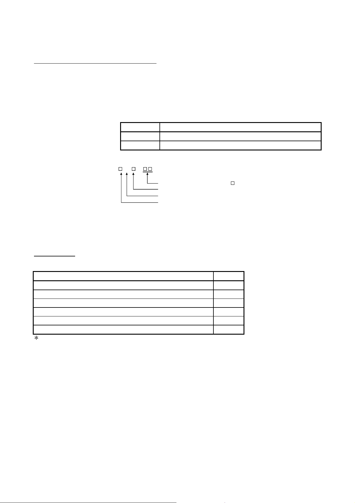
(1) Abbreviations for control station and normal station, and symbol format
This section explains abbreviations for control station and normal station, and
symbol format to be used in this manual.
(a) Abbreviation
Abbreviation Name
MP Control station
NS Normal station (Station that can serve as a control station)
(b) Symbol format
Mp —
Group number (1 to 32) : G
Station number (1 to 64)
Abbreviation
Network No. (1 to 239)
[Example]
P
1) Network No. 3, control station, station number 6: 3M
2) Network No. 5, normal station, station number 3: 5N
6
S
3
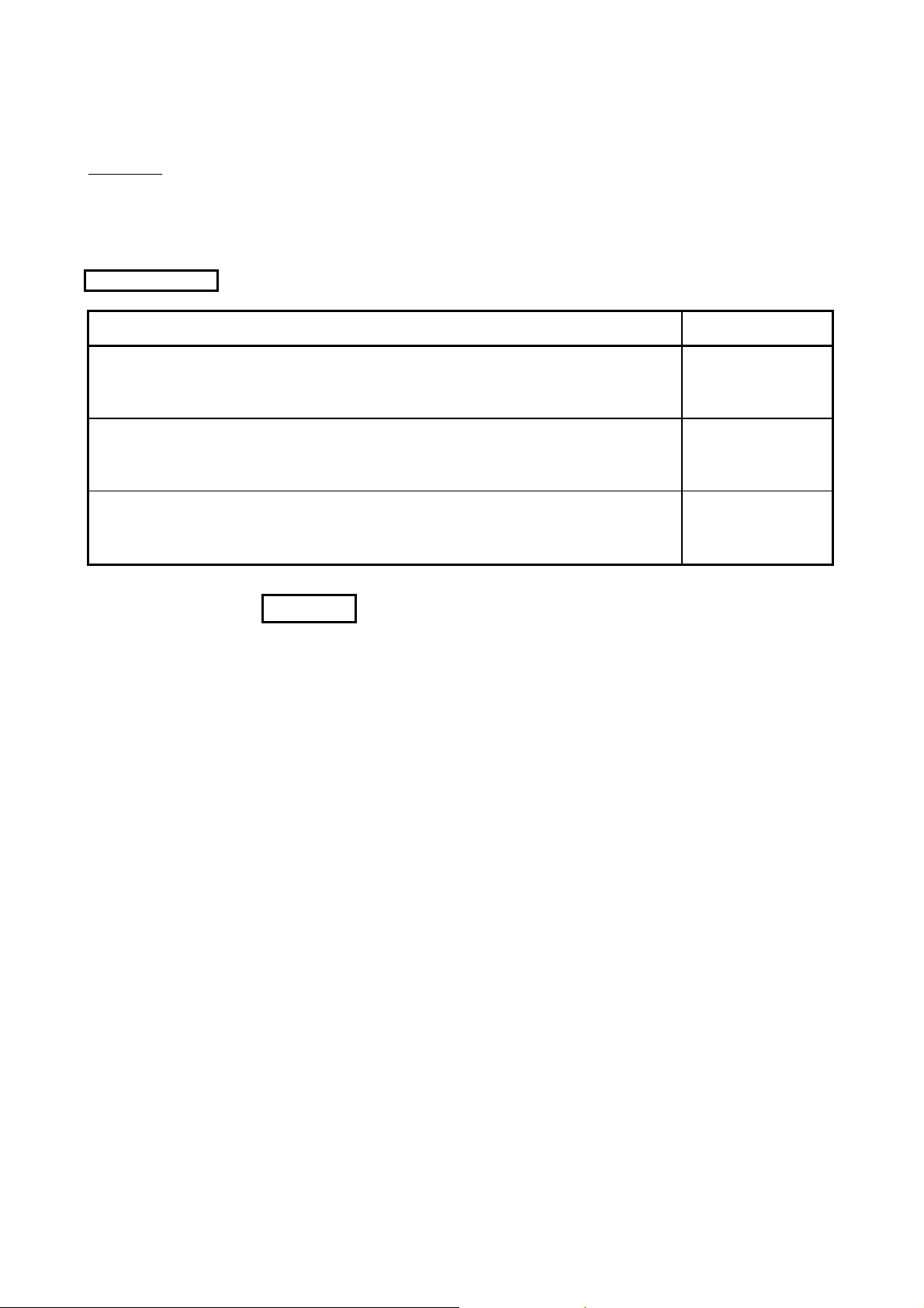
PACKING LIST
The packing list of the MELSECNET/H board is given below.
Item Quantity
Board 1
Connector set for external power supply cable(Q80BD-J71LP21S-25 only) 1
F-type connector (A6RCON-F) (Q80BD-J71BR11 only) 1
"Before Using the Product" 1
Software Package (CD-ROM) *1 1
Software license agreement 1
1: Manuals are stored on the CD-ROM in PDF format.
A - 21 A - 21
Page 24

MEMO
A - 22 A - 22
Page 25
A
1 OVERVIEW
MELSEC
1 OVERVIEW
1.1 Overview
Personal Computer
MELSECNET/H Board
(Q80BD-J71LP21-25)
This is a manual you read when using the MELSCNET/H board in the MELSECNET/H
mode or MELSECNET/H Extended mode. When using the MELSCNET/H board in
the MELSCNET/H network, refer to "Q Corresponding MELSECNET/H Network
System Reference Manual (PLC to PLC network)". Also, when using the board in the
MELSECNET/10 network system, refer to "For QnA/Q4AR Corresponding
MELSECNET/10 network system reference manual".
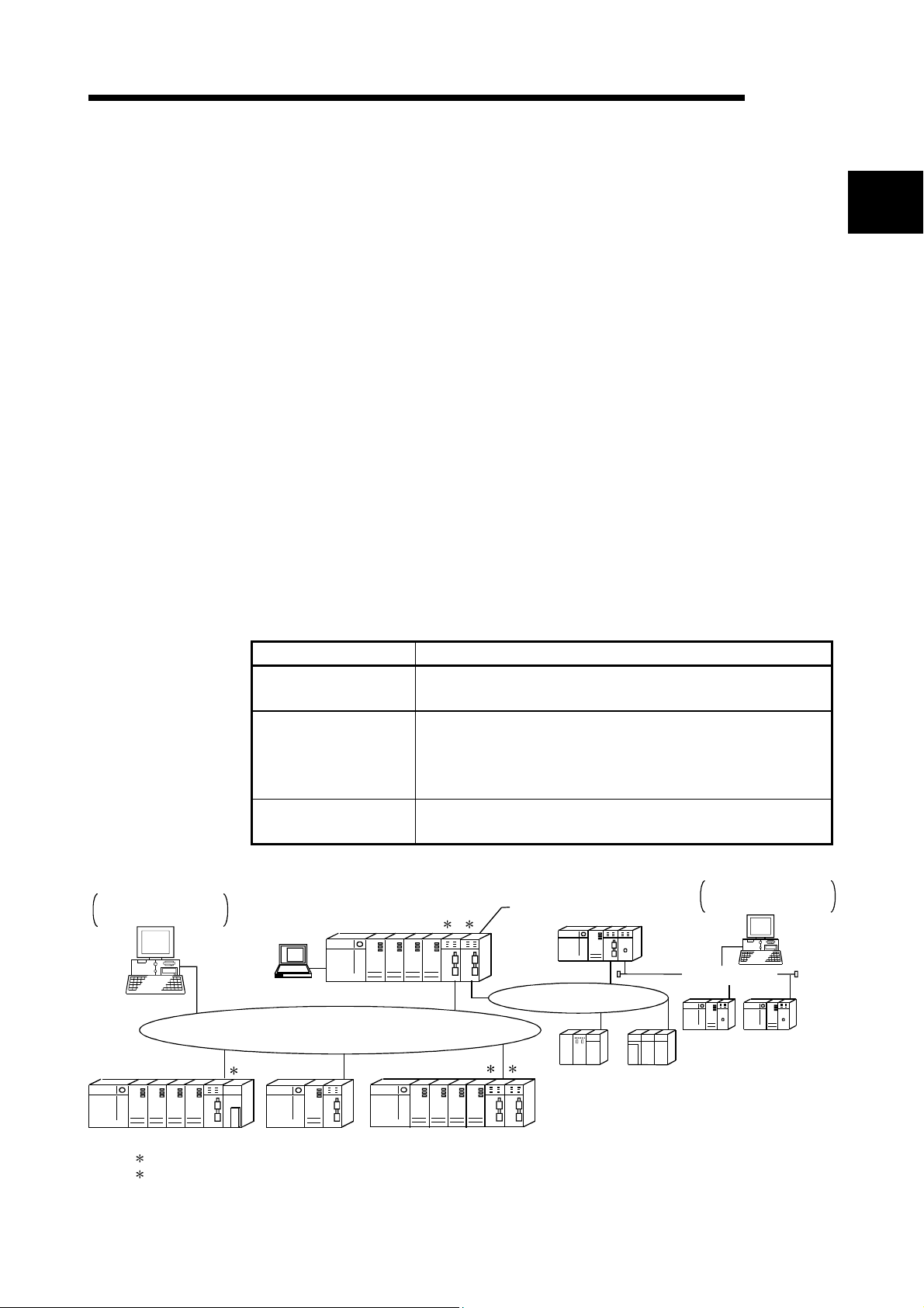
The MELSECNET/H is a network system which is used to connect multiple sequencer
modules and personal computers, and is equipped with functions and performance
realized in the MELSECNET/10 for general control of a production line.
In the MELSECNET/H, there is a network system which includes an optical loop
system (communication rates: 10 Mbps, 25 Mbps) and a coaxial bus system
(communications rate: 10 Mbps), enabling large volume communications at high
speeds.
Also, in order to improve the performance of the MELSECNET/10 network and achieve
upward compatibility, MELSECNET/H supports the MELSECNET/ H and
MELSECNET/H Extended modes (high performance, high speed mode) and the
MELSECNET/10 Mode (function compatible and performance compatible mode).
Mode Description
MELSECNET/H mode
MELSECNET/H Extended
mode
MELSECNET/10 mode
GX Developer
Set this mode when all CPUs within the network are QCPUs and
RCPUs.
The maximum number of link points per station has been increased
compared with the MELSECNET/H mode.
In excess of 2000 bytes, a maximum of 35840 bytes can be set.
Set this mode when the system uses many link points per station.
This mode is used to operate the MELSECNET/H board on a
MELSECNET/10 network.
Personal Computer
MELSECNET/H Board
(Q80BD-J71BR11)
MELSECNET /H
QCPU
1 2
MELSECNET/10
Mode
QCPU
MELSECNET /10
1
QCPU
MELSECNET/H
QCPU
1
QCPU
1 2
nU QnA
QCPUQCPU
1: The multiple CPU system compatible network module is for function version B and subsequent products.
2: In the multiple CPU system, a network module that becomes a relay station is the same as the control CPU.
1 - 1 1 - 1
Page 26
1 OVERVIEW
1
1.2 Features
MELSEC
POINT
(1) For MELSECNET/H, select QCPUs, RCPUs, and Q compatible network
modules.
(2) If QnACPU or ACPU are included in the same network, select MELSECNET/10
mode which is compatible with MELSECNET/10.
(3) All of network modules and MELSECNET/H boards within the same network
must be set to the same mode (network type)
1
.
1: MELSECNET/H mode, MELSECNET/H Extended mode and
MELSECNET/10 mode are available.
The features of the MELSECNET/H board are as shown below.
(1) A personal computer can be incorporated into MELSECNET/H.
By mounting the MELSECNET/H board in a personal computer, the personal
computer can be used as a MELSECNET/H or MELSECNET/10 control station
or normal station.
Board model name Supported network
Q80BD-J71LP21-25
Q81BD-J71LP21-25
Q80BD-J71LP21S-25
Q80BD-J71BR11
Q80BD-J71LP21G
Q80BD-J71LP21GE
MELSECNET/H Mode,
MELSECNET/H Extended Mode
MELSECNET/10 Mode MELSECNET/10 Optical Loop System
MELSECNET/H Mode,
MELSECNET/H Extended Mode
MELSECNET/10 Mode
MELSECNET/H Mode,
MELSECNET/H Extended Mode
MELSECNET/10 Mode MELSECNET/10 Optical Loop System
Mode
MELSECNET/H (10 Mbps / 25 Mbps) Optical
Loop System
MELSECNET/H (10 Mbps) Coaxial Bus
System
MELSECNET/10 Coaxial Bus System
MELSECNET/H (10 Mbps) Optical Loop
System
(2) By adopting the PCI/PCI ExpressRstandard, complicated switch
settings are no longer required.
The system can be used simply by installing the MELSECNET/H board in the
personal computer, then installing the software.
The channel No., station No. and other settings can be carried out easily in the
MNETH Utility.
(3) Compatibility with the previous MELSECNET/10 board’s operations
is maintained.
(a) Upward compatibility of user programs
Since MELSECNET/H board has the same number of the maximum
mountable board and channel number as the previous MELSECNET/10
board, the exiting user programs can be utilized.
(b) Compatible with the GX Developer, MX Links and MX
Component.
It is possible to access the programmable controller CPU using the GX
Developer, MX Links and MX Component from a personal computer where
the MELSECNET/H board is installed.
1 - 2 1 - 2
Page 27

1 OVERVIEW
MELSEC
(4) Compatible with multiple CPU systems.
By using station designations of logical station No. on the MNETH utility,
MELSECNET/H board is capable of communicating with a multiple CPU system.
(5) Compatible with redundant CPU systems.
Only by specifying whether the destination is a control or standby station using
the user program, access is simply made without considering the current
operating system state of the redundant CPU system.
(6) Compatible with MELSECNET/H Extended mode
The MELSECNET/H Extended mode is the extended MELECNET/H mode,
which is extended in the maximum number of link points per station. With this
mode, the maximum number of link points per station can be set to 2000 bytes or
more, i.e., up to 35840 bytes.
This mode is suitable for the system that needs many number of link points per
station.
(7) Drivers are provided for compatibility with each OS.
Each type of driver is provided, so it is easy to build a system that is compatible
with the user environment.
For details on the compatible operating system, refer to Section 2.5.
(8) User programming functions are provided.
Through MicrosoftRVisual BasicRand MicrosoftRVisual C++Rcompatible
functions, it is possible to carry out remote control of a programmable controller
CPU or read and write to devices, and user programs can be created easily.
1 - 3 1 - 3
Page 28
1 OVERVIEW
Personal
computer
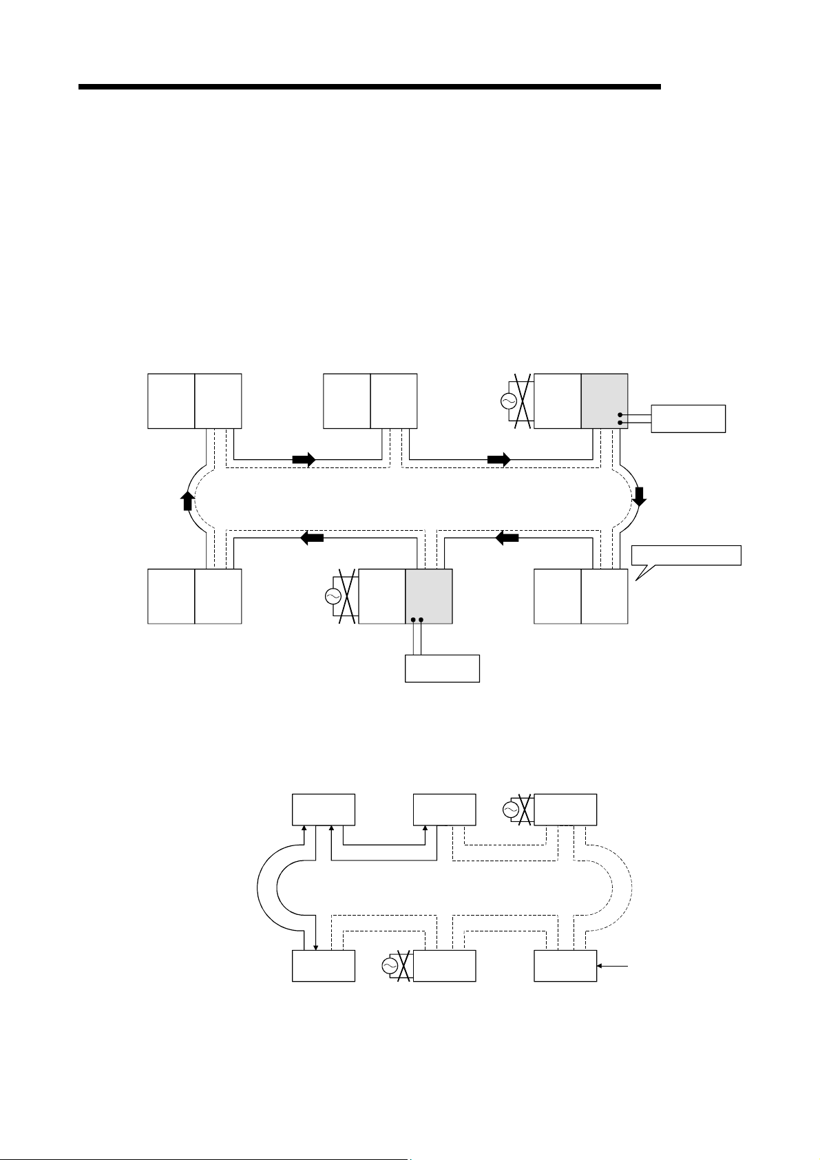
(9) External power supply allows continuous network communication
even during power-off of personal computer. (Function of the
Q80BD-J71LP21S-25)
Since power is supplied externally, the Q80BD-J71LP21S-25 can continue
network communication (baton passing) even if a personal computer is powered
off and data link cannot be performed.
Therefore, a normally operating station connected between other stations with
power-off computers will not be disconnected from the data link.
Another advantage is that the link scan time is stabilized since loopback can be
also prevented.
Personal
computer
Normal station
(Station No.3)
Q80BD
-J71
LP21S
-25
Control station
(Station No.1)
Q80BD
-J71
LP21
-25
Normal station
(Station No.2)
Q
CPU
QJ71
LP21
-25
MELSEC
External power
supply
Personal
computer
Q80BD
-J71
LP21
-25
Normal station
(Station No.6)
Data link continued
Personal
computer
Normal station
(Station No.5)
Q80BD
-J71
LP21S
-25
External power
supply
CPU
Q
Normal station
(Station No.4)
QJ71
LP21
-25
When station No. 3 and No.5 use MELSECNET/H boards without the external
power supply function and if their personal computers are powered off, station
No.4 is cut off from the network as well as No.3 and No.5.
Personal computer
Station No.1 Station No.2 Station No.3
Station No.6 Station No.5 Station No.4
Personal computer
Disconnected
1 - 4 1 - 4
Page 29
2 SYSTEM CONFIGURATION
MELSEC
2 SYSTEM CONFIGURATION
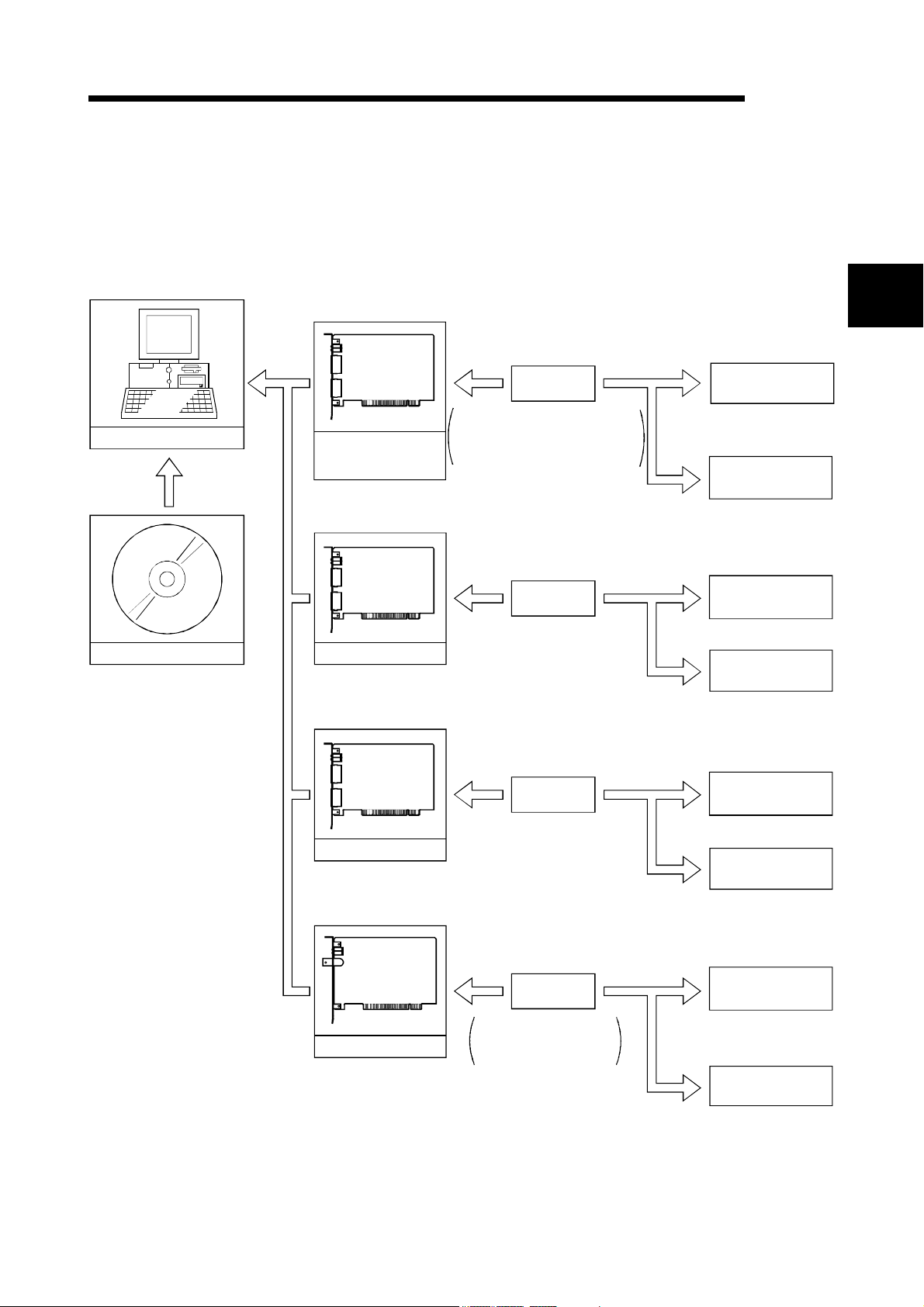
2.1 MELSECNET/H Board System Configuration
The system configuration when the MELSECNET/H board is mounted to a personal
computer is shown below.
Install
Type of cable : SI
Personal Computer
Install
SW0DNC-MNETH-B
Q
80BD-J71LP21-25
Q81BD-J71LP21-25
Q80BD-J71LP21S-25
Q80BD-J71LP21G
Q80BD-J71LP21GE
Optical fiber
cable
H-PCF
Broad-band H-PCF
QSI
Optical fiber
cable
(Type of cable : GI)
Optical fiber
cable
(Type of cable : 62.5GI)
MELSECNET/H
mode,
MELSECNET/H
Extended mode
MELSECNET/10
mode
MELSECNET/H
mode,
MELSECNET/H
Extended mode
MELSECNET/10
mode
MELSECNET/H
mode,
MELSECNET/H
Extended mode
MELSECNET/10
mode
MELSECNET/H
Optical loop system
MELSECNET/10
Optical loop system
MELSECNET/H
Optical loop system
MELSECNET/10
Optical loop system
MELSECNET/H
Optical loop system
MELSECNET/10
Optical loop system
2
MELSECNET/H
mode,
MELSECNET/H
Q80BD-J71BR11
Extended mode
Coaxial cable
Type of cable : 3C-2V
5C-2V
5C-FB
MELSECNET/10
mode
MELSECNET/H
Coaxial bus system
MELSECNET/10
Coaxial bus system
2 - 1 2 - 1
Page 30
2 SYSTEM CONFIGURATION
2
MELSEC
POINT
(1) When using the MELSECNET/H Extended mode
(a) Use the MELSECNET/H board of ROM version 2X or later and SW0DNC-
(b) When assigning 2000 bytes or more to the number of link points sent by a
(2) When using the Q80BD-J71LP21S-25
Use the SW0DNC-MNETH-B version 12N or later.
(3) When using the Q80BD-J71LP21-25, Q81BD-J71LP21-25 or Q80BD-
J71LP21S-25 at a communication speed of 25Mbps, errors may occur at all
stations if multiple boards with the same network number are installed, or the
operating systems are started up/shut down or the boards are reset
simultaneously on the adjacent personal computers. In this case, set the
communication speed to 10Mbps.
(4) If the QnACPU or ACPU are included in the same network, select
MELSECNET/10 mode which is compatible with MELSECNET/10.
MNETH-B version 11M or later.
station, set all stations including control stations and normal stations to the
MELSECNET/H Extended mode.
2 - 2 2 - 2
Page 31

r
2 SYSTEM CONFIGURATION
2.2 Single Network System
A single network system is one system that connects the control station and the normal
stations with an optical fiber cable or a coaxial cable.
2.2.1 Optical loop system
In the optical loop system, 1 control station and 63 normal stations (a total of 64
stations) can be connected. Any station number can be assigned as the control station.
However, only one station can be set as the control station per system.
In the following sample system, station number 1 has been assigned as the control
station.
Station No. 1
(control station)
Personal
computer
Q80BD-
J71LP21-25
Station No. 2
(normal station)
QCPU
Power supply
QJ71
LP21-25
Station No. 64
(normal station)
QCPU QJ71
LP21
Power supply
MELSEC
2.2.2 Coaxial bus system
In the coaxial bus system, 1 control station and 31 normal stations (a total of 32
stations) can be connected. As in the optical loop system, any station number can be
assigned as the control station. However, only 1 station can be assigned as the control
station per system.
Station No. 1
(control station)
Personal
computer
Q80BDJ71BR11
Terminal resistor
A6RCON-R75
Optical fiber cable
Station No. 2
(normal station)
QJ71
QCPU QCPU
BR11
Power supply
Coaxial cable
Station No. 32
(normal station)
QJ71
BR11
Power supply
Terminal resiste
A6RCON-R75
2 - 3 2 - 3
Page 32

2 SYSTEM CONFIGURATION
2.2.3 Setting items
In a single network system, the items which need to be set in the case that the
MELSECNET/H board is used as the control station or normal station are as follows.
MELSECNET/H board settings are set by the MNETH Utility.
Channel setting
Network No.
Group No.
Station No.
Control station/ Normal station
Mode Setting
Routing parameter setting
Common
parameter
setting
Opposite party setting
(Logical station No.)
Driver setting
2.2.4 Usable device ranges
MELSEC
Setting item Control station Normal station Reference section
Section 9.2.2
Section 9.2.3
Section 9.2.4
Section 9.2.5
Section 9.2.10
Section 9.2.11
B, W setting
X, Y setting
Reserved station setting
Supplementary setting
: Setting necessary : Set as necessary : Setting unnecessary
The MELSECNET/H board can be used within the following device ranges for the
following devices on the MELSECNET/H board.
Device Usable range
LB
LW
LX
LY
0H to 3FFFH
(16384 points)
0H to 3FFFH
(16384 points)
0H to 1FFFH
(8192 points)
0H to 1FFFH
(8192 points)
The function expansion areas of 2000H to 3FFFH are used for
the low-speed cyclic transmission. All areas can be used for the
normal cyclic transmission.
The use ranges for each MELSECNET/H board and network
module need to be assigned in the parameter settings for the
control station.
The use ranges for each MELSECNET/H board and network
module need to be assigned in the parameter settings for the
control station.
If the MELSECNET/H board is used in the MELSECNET/10 mode, the device range
for LB/LW becomes 0
H to 1FFFH (8192 points).
2 - 4 2 - 4
Page 33

2 SYSTEM CONFIGURATION
2.3 Multiple Network System
A multiple network system is a system where multiple networks are connected by relay
stations.
POINT
(1) The network No. can be set at any desired No. in the range 1 to 239.
(2) The MELSECNET/H board cannot be used as a relay station.
Please use the network module as a relay station.
2.3.1 Configuration
MELSEC
Control station
1M
P1
Personal
computer
Q80BD-
J71LP21-25
QJ71
QCPU
LP21-25
Power supply
1N
S3
Normal
station
The following example shows how three networks can be connected.
Network No.1
QJ71
BR11
Control station
3M
S2
Control station
2M
P1
QJ71
LP21
Network No.3
Q80BDJ71BR11
Personal
computer
3NS3
Normal station
Network No.2
Power supply
Normal station
1N
QCPU
QJ71
LP21
Power supply
P
1
QJ71
QCPU QJ71
BR11
Power supply
3NS2
Normal station
Normal station
Personal
computer
J71LP21-25
QCPU
LP21-25
Power supply
QCPU
BR11
3NS4
Normal station
2N
S2
Q80BD-
QJ71
Normal station
2N
S3
2 - 5 2 - 5
Page 34

2 SYSTEM CONFIGURATION
2.3.2 Setting items
Setting items in the case that the MELSECNET/H board is used as a control station or
normal station in a multiple network system are explained below.
MELSECNET/H board settings are performed by the MNETH Utility.
Channel setting
Network No.
Group No.
Station No.
Control station/ Normal station
Mode setting
Routing parameter setting
Common
Parameter
Setting
Opposite party setting
(Logical station No.)
Driver setting
2.3.3 Usable device range
MELSEC
Setting item Control station Normal station Reference section
Section 9.2.2
Section 9.2.3
Section 9.2.4
Section 9.2.5
Section 9.2.10
Section 9.2.11
B, W setting
X, Y setting
Reserved station setting
Supplementary setting
The same device range as is used for a single network system (section 2.2.4) can be
used.
2 - 6 2 - 6
Page 35

2 SYSTEM CONFIGURATION
2.4 If used in a Multiple CPU System or Redundant CPU System
For cautions in the case of installing MELSECNET/H in a multiple CPU system or
redundant CPU system, refer to "Q Corresponding MELSECNET/H Network System
Reference Manual (PLC to PLC network)."
POINT
When accessing a multiple CPU system or Redundant CPU system, use the
MELSECNET/H board and network module of the following function versions.
MELSEC
MELSECNET/H board
Access to multiple
CPU system
Access to Redundant
CPU system,
All versions available Function version B or later
Function version D or later1
Programmable controller
side network module
Function version D or later
1: When using a MELSECNET/H board of function version D or earlier,
access to a redundant CPU is not performed normally.
2 - 7 2 - 7
Page 36

2 SYSTEM CONFIGURATION
MELSEC
2.5 Operating Environment
The following table shows the operating environment for the MELSECNET/H board.
Item Description
Microsoft
Personal
computer
CPU
Required memory
PCI bus
specifications
PCI ExpressR
Bus specifications
System requirements of the operating system must be met.
For Q80BD-J71LP21-25, Q80BD-J71LP21S-25, Q80BD-J71LP21G, and Q80BDJ71BR11
Compliant with PCI standard Rev.2.2 (5V DC, 32-bit bus, Reference clock : 33MHz)
For Q81BD-J71LP21-25
Compliant with PCI Express
Reference clock : 100MHz)
Available hard disk space 1GB or more
Disk drive CD-ROM disk drive
Display Resolution: 800 600 dot or higher (Recommended: 1024 768 dot)
Windows 10 (Home, Pro, Enterprise, Education)
Windows 8.1, Windows 8.1 (Pro, Enterprise)
Windows Server
Windows 8, Windows 8 (Pro, Enterprise)
Windows Server 2012 (Standard)
Windows 7 (Home Premium, Professional, Ultimate, Enterprise)
Windows Server 2008 R2 (Standard, Enterprise)2
When using any of the following operating systems, use SW0DNC-MNETH-B with the
Operating system
(English version)
1
version 29F or earlier.
Windows Server 2008 (Standard (x86, x64), Enterprise (x86, x64))
Windows Vista
Windows Server 2003 R2 (Standard (x86, x64), Enterprise (x86, x64))
Windows XP
When using any of the following operating systems, use SW0DNC-MNETH-B with the
version 25B or earlier.
Windows 2000 (Professional)
Windows NT
Windows 98, Windows 98 Second Edition
Windows 95
Visual Basic
Programming language1
(English version)
Visual Studio
Visual Studio 2008, Visual Studio 2005, Visual Studio.NET 2003,
Visual Basic 6.0, Visual C++ 6.0, Visual Basic 5.0, Visual C++ 5.0
1: For a combination of the operating system and the programming language, refer to the Microsoft Knowledge Base.
2: Apply Service Pack1 and Security Update for Windows (KB3033929). Otherwise, use SW0DNC-MNETH-B with the
version 29F or earlier.
3: A 64-bit version is not supported.
POINT
For the information on how to obtain SW0DNC-MNETH-B of the version 29F or
earlier, refer to Appendix 7.
R
WindowsRsupported personal computer
R
standard Rev.1.0a (3.3 V DC, Link width : 1lane,
R
2012 R2 (Standard)
2
R
(Home Basic, Home Premium, Business, Ultimate, Enterprise)3
R
(Professional)
R
Workstation 4.0 SP3 or later
R
, Visual C++R in the following development tools
R
2015, Visual Studio 2013, Visual Studio 2012, Visual Studio 2010,
3
2 - 8 2 - 8
Page 37

2 SYSTEM CONFIGURATION
(1) Instructions for personal computer
(a) PCI standard
Using a personal computer not compliant with the PCI or PCI ExpressR
standard may result in a problem due to poor electrical contact, erroneous
operation, etc.
For details on the number of boards that can be installed, installation slot
and occupied slots, refer to Section 3.2.
(b) The functions being added
Hyper-Threading technology 11M or later
Multiprocessor 19V or later
MELSEC
Operating environment Supported version of SW0DNC-MNETH-B
2 - 9 2 - 9
Page 38

2 SYSTEM CONFIGURATION
(2) Instructions for operating system
(a) Supported version of SW0DNC-MNETH-B
Operating system
Windows 10
Windows 8.1, Windows Server 2012 R2
Windows 8, Windows Server 2012
Windows 7 (64-bit version),
Windows Server 2008 R2
Windows 7 (32-bit version)
Windows Server 2008 (64-bit version)
Windows Server 2008 (32-bit version)
Windows Vista
Windows Server 2003 R2 (64-bit version)
Windows Server 2003 R2 (32-bit version)
Windows XP
Windows 2000
Windows NT Workstation, Windows 98,
Windows 95
(b) User authority
Log on as a user having administrator authority.
Installation, uninstallation and usage of utilities are available only by the
administrator's authority.
(c) .NET Framework 3.5
When using one of the following operating system, .NET Framework 3.5
is required.
• Windows 10
• Windows 8.1
• Windows Server 2012 R2
• Windows 8
• Windows Server 2012
Enable the .NET Framework 3.5 (including .NET 2.0 or 3.0) in "Turn
Windows features on or off" on the control panel.
(d) Upgrading and updating the operating system
Upgrading the operating system and updating from Windows 8 to Windows
8.1 are not supported.
Install SW0DNC-MNETH-B by following the procedure.
1. Uninstall SW0DNC-MNETH-B.
2. Upgrade or update the operating system.
3. Install SW0DNC-MNETH-B with the version supporting the changed
operating system.
MELSEC
Supported version
Q80BD-J71LP21-25,
Q80BD-J71LP21S-25,
Q80BD-J71LP21G,
Q80BD-J71BR11
17T to 29F 19V to 29F
70H to 90K, 10L to 29F 19V to 29F
25B or earlier 19V to 25B
25B or earlier Not supported
30G or later
27D or later
26C or later
23Z or later
21X or later
23Z to 29F
21X to 29F
23Z to 29F
19V to 29F
Q81BD-J71LP21-25
2 - 10 2 - 10
Page 39

2 SYSTEM CONFIGURATION
(e) The functions cannot be used
If an attempt is made to use any of the following functions, this product may
not operate normally.
• Activating the application with Windows
• Simplified user switch-over
• Remote desktop
• Power save mode (Hibernate, Sleep)
• Fast startup
• The language switching function set by Regional and Language Options
• Windows XP Mode
• Windows Touch or Touch
• Modern UI
• Client Hyper-V
• Server Core Installation
• Tablet mode
• Virtual desktop
In the following cases, the screen of this product may not work properly.
• The size of the text and/or other items on the screen are changed to
values other than default values (such as 96 DPI, 100%, and 9 pt).
• The resolution of the screen is changed in operation.
• The multi-display is set.
R
compatible mode.
MELSEC
REMARK
• When exiting the operating system, always shut down the computer.
• For the behavior when entering the power save mode, refer to Appendix 9.
2 - 11 2 - 11
Page 40

2 SYSTEM CONFIGURATION
(3) Instructions for user program
(a) Supported version of SW0DNC-MNETH-B
32-bit version user program*1 All versions
64-bit version user program*2 Version 23Z or later
(b) Language environment
User programs created in the Japanese environment work only in the
Japanese environment.
User programs created in the English environment work only in the English
environment.
(c) MELSEC data link library
For precautions when using MELSEC data link library, refer to MELSEC
Data Link Library Reference Manual.
MELSEC
User program
1: Programs can be created and executed on the 64-bit version operating system.
2: Programs can be created on the 32-bit version operating system, however, the
following dialog box appears and cannot be executed.
<When using Windows 7 (32-bit version)>
Supported version of
SW0DNC-MNETH-B
2 - 12 2 - 12
Page 41

p
3 SPECIFICATIONS
MELSEC
3 SPECIFICATIONS
This section explains the MELSECNET/H board general specifications, performance
specifications.
3.1 General Specifications
Item Specifications
Operating ambient temperature 0 to 55 °C
Storage ambient temperature -25 to 75 °C
Operating ambient humidity
Storage ambient humidity
Vibration resistance
Shock resistance
Operating atmosphere
Operating altitude1
Installation location Inside a control panel
Over-voltage category 2
Pollution rate 3
1: Do not use or store the board under pressure higher than the atmospheric pressure of altitude 0m.
Doing so may cause a malfunction.
2: This indicates the section of the power supply to which the equipment is assumed to be connected
between the public electrical power distribution network and the machinery within the premises. Category
II applies to equipment for which electrical power is supplied from fixed facilities. The surge voltage
withstand level for up to the rated voltage of 300 V is 2500 V.
3: This index indicates the degree to which conductive material is generated in terms of the environment in
which the equipment is used. Pollution level 2 is when only non-conductive pollution occurs. A temporary
conductivity caused by condensation must be expected occasionally.
This section explains the MELSECNET/H board general specifications.
5 to 95 % RH, non-condensing
Under intermittent vibration
Compliant with
JIS B 3502 and
IEC 61131-2
IEC 61131-2 (147 m/s
Frequency
5 to 8.4 Hz
8.4 to 150 Hz 9.8m/s2
Frequency
5 to 8.4 Hz
8.4 to 150 Hz 4.9m/s
Compliant with JIS B 3502
Constant
acceleration
—
Under continuous vibration
Constant
acceleration
—
2
, 3 times each in X, Y, and Z directions)
No corrosive gases
0 to 2000 m
II or less
2 or less
2
Half
am
litude
3.5 mm
—
Half
amplitude
1.75 mm
—
and
10 times each in
Sweep count
X, Y and Z
directions
Sweep count
—
3
REMARK
General specifications both MELSECNET/H board and a personal computer must
be satisfied after installation.
3 - 1 3 - 1
Page 42

3 SPECIFICATIONS
3.2 Performance Specifications
MELSEC
3
Maximum links
in 1 network
Maximum links in 1 station
Communications rate2 25 Mbps / 10 Mbps 10 Mbps
Number of stations
Connected to 1 network
Connection cable Optical fiber cable
Total extension cable length 30km (98430 ft.)
Between
stations
length
Maximum networks 239
Maximum number of groups 32 (When in the MELSECNET/10 Mode: 9)
Transmission channel format Duplex loop
Communications system Token ring system
Synchronization system Frame synchronization system
Encoding system NRZI encoding (Non return to Zero inverted)
Transfer format HDLC Standard (Frame format)
Error control system CRC (X16 + X12 + X5 + 1) and retry by overtime.
RAS function
Transient transmission N: N communications
Special cyclic transmission Low speed cyclic transmission
Number of boards that can be
installed
Installation slot
Exclusive slots 1 slot 2 slot 1 slot
External
power
supply
5 V DC Internal current
consumption
3.3 V DC Internal current
consumption
Weight 0.10 kg 0.20 kg 0.11 kg
Item
25 Mbps
3
10 Mbps
Voltage — 20.4 to 31.2 V DC —
Current — 0.16 A —
Connector —
Suitable cable
size
MELSECNET/H Board performance specifications are shown below.
(1) Q80BD-J71LP21-25, Q81BD-J71LP21-25, Q80BD-J71LP21S-25,
Q80BD-J71LP21G, Q80BD-J71LP21GE
Specifications
Q80BD-J71LP21-25
LX/LY 8192 Points
LB 16384 Points (When in the MELSECNET/10 Mode2: 8192 Points)
LW 16384 Points (When in the MELSECNET/10 Mode
• MELSECNET/H mode, MELSECNET/10 mode2
{(LY + LB) / 8 + (2
• MELSECNET/H Extended mode
{(LY + LB) / 8 + (2
SI optical cable : 200m (656.2 ft.)
H-PCF optical cable : 400m (1312.4 ft.)
Broad-band H-PCF optical cable : 1km (3281 ft.)
QSI optical cable : 1km (3281 ft.)
SI optical cable : 500m (1640.5 ft.)
H-PCF optical cable : 1km (3281 ft.)
Broad-band H-PCF optical cable : 1km (3281 ft.)
QSI optical cable : 1km (3281 ft.)
• Loop back function (optical loop system only) by abnormal detection and cable disconnection.
• System down prevention through control station.
• Error detection by the link special relay and link special register.
etc.
PC PCI bus slot
(half size)
Q81BD-
J71LP21-25
LW)} ≤ 2000 bytes
LW)} ≤ 35840 bytes
64 Stations (Control station: 1; Normal station: 63)
PC PCI
Express
X1, X2, X4,
X8, X16 slot
(half size)
—
0.46 A — 0.46 A 0.45 A
— 0.95 A — —
Q80BD-J71LP21S-25 Q80BD-J71LP21G Q80BD-J71LP21GE
1
2
: 8192 Points)
2
— —
Maximum 4 boards
R
Connector set
(Accessory)
0.50 to 1.25 mm2
[AWG#20-16]
GI optical cable
: 2km (6562 ft.)
PC PCI bus slot (half size)
3 - 2 3 - 2
62.5 GI optical cable
: 2km (6562 ft.)
—
—
Page 43

3 SPECIFICATIONS
MELSEC
1: The CPU usage may be higher compared to that of Q80BD-J71LP21-25, Q80BD-J71LP21S-25, Q80BDJ71LP21G,
Q80BD-J71LP21GE, or Q80BD-J71BR11. (For the solutions to slow PC performance, refer to Section 14.8.)
2: MELSECNET/H board communications rate and Mode settings are performed using the MNETH Utility.
(For details, refer to Section 9.2.3)
3: L type and H type of the previous optical fiber cable (A-2-) differ in the distances between stations. (For details, refer
to Section 6.4.1)
(2) Q80BD-J71BR11
Item
Maximum links
in 1 network
LX/LY 8192 Points
LB 16384 Points (When in the MELSECNET/10 Mode1: 8192 Points)
LW 16384 Points (When in the MELSECNET/10 Mode
• MELSECNET/H mode, MELSECNET/10 mode
Maximum links in 1 station
{(LY + LB) / 8 + (2
• MELSECNET/H Extended mode
{(LY + LB) / 8 + (2
LW)} ≤ 2000 bytes
1
LW)} ≤ 35840 bytes
Communications rate1 10 Mbps
Number of stations Connected
to 1 network
32 Stations (Control station: 1; normal station: 31)
Connection cable Optical fiber cable Coaxial cable
Cable name
Total extension cable length in
1 network
3C-2V
5C-2V
5C-FB
Can be extended to 2.5 km (8202.5 ft.) using a repeater unit (A6BR10, A6BR10-DC).
Maximum networks 239
Maximum number of groups 32 (When in the MELSECNET/10 Mode: 9)
Transmission channel format Single Bus
Communications system Token bus system
Synchronization system Frame synchronization system
Encoding system NRZI encoding (Non return to Zero inverted) Manchester encoding
Transfer format HDLC Standard (Frame format)
Error control system CRC (X16 + X12 + X5 + 1) and retry by overtime.
• Loop back function (optical loop system only) by abnormal detection and cable disconnection.
RAS function
• System down prevention through control station.
• Error detection by the link special relay and link special register.
etc.
Transient transmission N:N communications
Special cyclic transmission Low speed cyclic transmission
Number of boards that can be
installed
Installation slot PC PCI bus slot (half size)
Exclusive slots 1 slot
5 V DC Internal current
consumption
Weight 0.11 kg
1: MELSECNET/H board communications rate and Mode settings are performed using the MNETH Utility.
(For details, refer to Section 9.2.3)
2: Depending on the number of stations connected, there are limits to the cable length between stations. (For details, refer
to Section 6.4.2)
Specifications
Q80BD-J71BR11
Total extension
cable length
Maximum 4 boards
0.67 A
1
1
Length between
stations
2
300m
2
500m
: 8192 Points)
3 - 3 3 - 3
Page 44

3 SPECIFICATIONS
3.3 Optical Fiber Cable Specification
For the optical fiber cable specification, refer to "Q Corresponding MELSECNET/H
Network System Reference Manual (PLC to PLC network)".
3.4 Coaxial Cable Specification
For the coaxial cable specification, refer to "Q Corresponding MELSECNET/H Network
System Reference Manual (PLC to PLC network)".
MELSEC
3 - 4 3 - 4
Page 45

A
f
4 FUNCTION
MELSEC
4 FUNCTION
4.1 Function List
Basic
functions
pplication
unctions
Cyclic transmission function
(Periodical communication)
RAS function
Direct access to link devices
Cyclic transmission function
(Periodical communication)
This chapter explains the function of MELSECNET/H board.
The following flowchart shows the function list for MELSECNET/H board.
Communication LB/LW
Communication LX/LY
Automatic return function
Control station switch function
Control station return control function
Loopback function (optical loop system)
Prevention of station failure by using external
power supply (optical loop system)
Diatnostic function
Driver WDT function
················································································································
Low-speed cyclic transmission
·········································································
······································································
·······················································
Refer to Q Corresponding
MELSECNET/H Network System
Reference Manual
(PLC to PLC network)
Section 6.5
Section 4.3
Section 12.1
Section 12.2
4
Transient transmission function
(Non-periodical communication)
Multiple transmission function (optical loop system)
Communication function
Routing function
Group function
·······································································
·········································································
···········································································
···························································
Section 12.3.1
Section 12.3.2
Section 12.3.3
Section 12.4
4 - 1 4 - 1
Page 46

4 FUNCTION
4.2 Specifications of the Link Data Sending/Receiving Processing Time
MELSEC
This section explains the link data sending/receiving processing in the MELSECNET/H
network system with MELSECNET/H board.
4.2.1 Link data sending/receiving processing
(1) Link data sending/receiving processing
4
In the cyclic transmission, communication is performed using the LB/LW/LX/LY
devices of the network module and MELSECNET/H board.
This section explains the case when the link relay (B) is used on the personal
computer side.
1) B0 on the sending station (personal computer) turns on.
2) By a link refresh, the B0 information is stored in the refresh data
storage area (LB) of the MELSECNET/H board.
3) The B0 information in the refresh data storage area (LB) is stored in
the link data storage area (LB).
4) By a link scan, the B0 information in the link data storage area (LB) is
stored in the link data storage area (LB) of the network module on the
receiving station.
5) The B0 information in the link data storage area (LB) is stored in the
refresh data storage area (LB).
6) By a link refresh, the B0 information is stored in the device memory
storage area (B) of the CPU module.
7) B0 on the receiving station turns on.
1: The link refresh interval is set on the "Driver" screen in the MNETH Utility.
2: Set by the GX Developer’s "Station Inherent Parameters." (If not set, they are stored in the common
parameters state.)
3: If the MELSECNET/H board is a control station, it is set in the "Common Parameter Setting" screen in
the MNETH Utility. If the network module is a control station, it is set in the GX Developer’s "Common
Parameters."
4: Set in the GX Developer’s "Network Refresh Parameters."
4 - 2 4 - 2
Page 47

4 FUNCTION
(2) Link scan and link refresh
The link scan is executed "asynchronous" with the sequence scan of the CPU
module.
The link refresh is executed by the "END processing" of the CPU module.
Sequence scan
0
END
Link refresh Link refresh Link refresh
0
END
0
END
MELSEC
0
END
Link scan
(3) Link data when a communication error station or communication
stop station occurs on the network
When a communication error or communication stop station occur on the network
during the data link, the receive data from those stations immediately before the
error occurrence is retained.
(A "communication stop station" refers to a station whose cyclic transmission has
been stopped by a peripheral device.)
(a) The receive data from a communication error station or communication stop
station is retained by a normally communicating station.
(b) The receive data from other station is retained by a communication stop
station.
(Example)
When a communication error has occurred to 1N
Communication
1MP1 1NS2
Cable disconnection
error station
S2 due to cable disconnection
1NS3
Cable disconnection
Link data status after disconnection
1MP11N
Link data Link data Link data
1MP1
1N
2
S
1N
3
S
1NS2
1MP1
1NS2
1N
3
S
· · · · · · Area where the link data is retained
1MP1
1N
1N
3
S
2
S
3
S
4 - 3 4 - 3
Page 48

4 FUNCTION
MELSEC
(4) SB/SW when a communication error station/communication stop
station occurs on the network
The status of whether there are any communication error/communication stop
stations on the network can be checked with the link special relay/register
(SB/SW).
Use them as interlocks for programs.
For interlock program examples, refer to the following manual.
Q Corresponding MELSECNET/H Network System
Reference Manual (PLC to PLC network)
Link special relays and registers
relay/register
SB20
SB47
SB49 Shows the cyclic transmission status of the host. Normal Abnormal
SB70
SW70 to 73
SB74
SW74 to 77
Indicates the communication status between
MELSECNET/H board and personal computer.
Shows the baton pass execution status of the
host.
Shows the baton pass execution status of all
stations (including the host). However, it only
shows the status for the number of stations set
with parameters.
Shows the baton pass execution status of each
station.
Each bit corresponds to the status of each
station.
Shows the cyclic transmission status of all
stations (including the host). However, it only
shows the status for the number of stations set
with parameters.
Shows the cyclic transmission status of each
station.
Each bit corresponds to the status of each
station.
Description
The baton pass is
being executed
The baton pass is
being executed on
all stations
The baton pass is
being executed
All stations
Signal status Link special
Off On
Normal Abnormal
The baton pass is
Occurrence of
communication
stop station
The baton pass is
Occurrence of
normal
Normal Abnormal
abnormal station
stopped
stopped
SB7A
SB7A, 7B
SW1FC to SW 1FF
Shows the low-speed cyclic transmission status.
The transmission completion is indicated by the
on/off status of either bit SB7A or 7B.
Shows the redundant CPU system status
(Control or Standby) of each station.
Each bit corresponds to each station status.
Control system
SB7B
Low-speed cyclic interval
1
Standby system
1: Stations in other than the redundant CPU system configuration are OFF.
4 - 4 4 - 4
Page 49

4 FUNCTION
4.3 Driver WDT function
Driver WDT function monitors the operation of the software (operating system, driver)
inside the hardware by the timer function on MELSECNET/H board.
When the driver cannot reset the timer of the board within the specified driver WDT
monitoring time, MELSECNET/ board detects driver WDT error.
Driver WDT function detects driver operation delay due to the access error from the
driver to MELSECNET/H board or system high load.
(1) Driver WDT settings
REMARK
(2) When the driver WDT error has occurred
(1) When the multiple applications in which MELSEC data link library is used are
(2) For the troubleshooting, refer to section 14.7.2.
MELSEC
For the setting method, refer to section 9.2.11.
The driver WDT function is set to invalid as a default.
The following shows the operation when driver WDT error has occurred.
1) MELSECNET/H board and the driver stop communication and are
disconnected from the network in order to avoid an erroneous output.
A CPU stop error occurs when checking the MELSECNET/H board from
other station on which the driver WDT error has occurred.
2) RUN LED flicks and SD LED turns ON on the MELSECNET/H board.
3) "-28158 (9202H) Driver WDT error" occurs when accessing MELSECNET/H
board from the application program in which the MELSECNET/H utility and
MELSEC data link library function are used.
POINT
executed, driver WDT error is returned to all the programs. However, only the
MELSECNET/H board in which the driver WDT error has occurred is
recognized as an error station on the network.
When using driver WDT function, set the monitoring timer considering the
margin of the personal computer load.
4 - 5 4 - 5
Page 50

4 FUNCTION
MEMO
MELSEC
4 - 6 4 - 6
Page 51

5 EMC AND LOW VOLTAGE DIRECTIVE
5 EMC AND LOW VOLTAGE DIRECTIVE
Compliance with the EMC Directive, which is one of the EU directives, has been
mandatory for the products sold within EU member states since 1996 as well as
compliance with the Low Voltage Directive since 1997.
To prove the compliance, manufactures must issue an EC Declaration of Conformity
and the products must bear a CE marking.
(1) Sales representative in EU member states
The authorized representative in EU member states will be:
Company name: Mitsubishi Electric Europe BV
Address: Mitsubishi-Electric-Platz 1, 40882 Ratingen, Germany
5.1 Measures to comply with the EMC Directive
The EMC Directive sets two requirements for compliance: emission (conducted and
radiated electromagnetic energy emitted by a product) and immunity (the ability of a
product to not be influenced by externally generated electromagnetic energy).
This section summarizes the precautions for machinery constructed with the
MELSECNET/H board to comply with the EMC Directive.
These precautions are based on the requirements of the EMC Directive and the
harmonized standards. However, they do not guarantee that the entire machinery
constructed according to the descriptions complies with the EMC Directive.
The manufacture of the machinery must determine the testing method for compliance
and declare conformity to the EMC Directive.
MELSEC
5
5 - 1 5 - 1
Page 52

5 EMC AND LOW VOLTAGE DIRECTIVE
MELSEC
5.1.1 EMC Directive related standards
The standards applicable to the EMC Directive are listed below.
All test items were tested by installing each device on a personal computer bearing a
CE certification logo.
Standard Test item Test description Value specified in standard
EN61131-2 :
2007
CISPR16-2-3
Radiated emission
CISPR16-2-1,
CISPR16-1-2
Conducted emission 1
(1) Emission requirements
1
1: The tests were conducted installed in a control panel.
2
(2) Immunity requirements
5
Standard Test item Test description Value specified in standard
EN61000-4-2
Electrostatic discharge
EN61131-2 :
2007
immunity
EN61000-4-3
Radiated, radio-frequency,
electromagnetic field
immunity
EN61000-4-4
Fast transient burst
immunity
EN61000-4-5
Surge immunity
1
1
1
1
EN61000-4-6
Conducted RF immunity
EN61000-4-8
Power-frequency magnetic
field immunity 1
EN61000-4-11
Voltage dips and
interruption immunity 1
1: The tests were conducted installed in a control panel.
The electromagnetic wave
which the product emits to the
external space is measured.
The noise level which the
product emits to the power line
is measured.
• 30M-230MHz
QP: 40dB V/m (10m in measurement range)
• 230M-1000MHz
QP: 47dB V/m (10m in measurement range)
• 0.15 to 0.5MHz, QP: 79dB, Mean: 66dB
• 0.5 to 30MHz, QP: 73dB, Mean: 60dB
: QP: Quasi-peak value, Mean: Average value
An electrostatic discharge is
applied to the enclosure of the
equipment.
An electric field is radiated to
the product.
Burst noise is applied to power
lines and signal lines.
Lightning surge is applied to
power lines and signal lines.
High-frequency noise is applied
1
to power lines and signal lines.
The product is immersed in the
magnetic field of an induction
coil.
Power voltage is momentarily
interrupted.
• 8kV Air discharge
• 4kV Contact discharge
80% AM modulation@1kHz
• 80 to 1000MHz: 10V/m
• 1.4 to 2.0GHz: 3V/m
• 2.0 to 2.7GHz: 1V/m
• AC/DC power, I/O power, and
AC I/O (unshielded) lines: 2kV
• DC I/O, analog, and communication lines: 1kV
• AC power, AC I/O power, and
AC I/O (unshielded) lines: 2kV CM, 1kV DM
• DC power and DC I/O power lines:
0.5kV CM, 0.5kV DM
• DC I/O, AC I/O (shielded), analog,
communication: 1kV CM
0.15 to 80MHz, 80% AM modulation @1kHz,
10Vrms
50Hz/60Hz, 30A/m
• 0%, 0.5 period, starting at zero-crossing
• 0%, 250/300 period (50/60Hz)
• 40%, 10/12 period (50/60Hz)
• 70%, 25/30 period (50/60Hz)
2
2
5 - 2 5 - 2
Page 53

5 EMC AND LOW VOLTAGE DIRECTIVE
5.1.2 Installation in a control panel
The installation in the control board ensures safety as well as effective shielding of
personal computer-emitted electromagnetic noise.
(1) Control panel
(a) Use a conductive control panel.
(b) Mask off the area used for grounding when securing the top or bottom plate
to the control panel using bolts.
(c) To ensure electrical contact between the inner plate and the control panel,
mask off the bolt installation areas of an inner plate so that conductivity can
be ensured in the largest possible area.
(d) Ground the control panel with a thick ground cable so that low impedance
can be ensured even at high frequencies.
(e) Keep the diameter of the holes on the control panel to 10cm or less. If the
diameter is larger than 10cm, electromagnetic wave may be emitted. In
addition, because electromagnetic wave leaks through a clearance
between the control panel and its door, reduce the clearance as much as
possible. Use of EMI gaskets (sealing the clearance) can suppress
undesired radiated emissions.
The tests by Mitsubishi were conducted using a control panel having the
damping characteristics of 37dB (maximum) and 30dB (average)
(measured at 3m distance, 30 to 300MHz).
(2) Wiring power and ground cables
The power supply cable and ground cable for a personal computer should be laid
out as follows:
(a) Provide a ground point to the control panel near the power supply module.
Ground the LG and FG terminals of the power supply module to the ground
point with the thickest and shortest ground cable possible (30cm or shorter).
(b) Twist the ground cable leading to the ground point with the power supply
cable. By twisting it with the ground cable, the noise leaking from the power
supply cable may be grounded at a higher rate. However, twisting the
power supply cable with the ground cable may not be necessary if a noise
filter is installed on the power supply cable.
MELSEC
5 - 3 5 - 3
Page 54

5 EMC AND LOW VOLTAGE DIRECTIVE
5.1.3 Cables
Use a shielded cable for the cable extended out of the control panel.
If a shielded cable is not used or not grounded correctly, the noise immunity will not
meet the required value.
(1) Grounding a shield cable
(a) Ground the shield of the shield cable as near the exit as possible from the
control panel.
If the ground point is not near the outlet, the cables after the ground point
will cause electromagnetic induction, and will generate a higher harmonic
noise.
(b) Ground the exposed shield to large area on the control panel. A clamp fitting
can be used as shown below.
In this case, mask off the inner wall surface of the control panel, where
comes in contact with the fitting.
Screw
MELSEC
Clamp fitting
Paint mask
Shielded cable
POINT
Grounding with a vinyl-coated wire soldered onto the shield of the shielded cable as
shown below is not recommended.
Doing so will raise the high-frequency impedance, resulting in loss of the shielding
effect.
Shielded cable
Wire
Crimp terminal
(2) Treatment of the coaxial cable ground
(a) Always use a double-shielded coaxial cable (MITSUBISHI CABLE : 5C-2V-
CCY) for the coaxial cables Q80BD-J71BR11. Ground the double-shielded
coaxial cable by connecting its outer shield to the ground.
Refer to (1) for the grounding of the shield.
Shield
Ground here
(b) Make sure to install a ferrite core for the cable.
5 - 4 5 - 4
Page 55

5 EMC AND LOW VOLTAGE DIRECTIVE
(3) Grounding cables with a cable clamp
Ground the shield of the external wiring cable to the control panel with the
AD75CK cable clamp (Mitsubishi).(Ground the shield within 20 to 30cm from the
module.).
MELSECNET/H board
Inside the control panel
MELSEC
AD75CK
20 to 30cm
For details on the AD75CK, refer to the following.
• AD75CK-type Cable Clamping Instruction Manual
5.1.4 Ferrite core
Ferrite core is effective for reducing radiated noise in the 30MHz to 100MHz frequency
band.
It is recommended to install a ferrite core if a shield cable extended out of the control
panel does not provide sufficient shielding effects.
Install a ferrite core to the cable in the position immediately before the cable is
extended out of the control panel. If the installation position is not appropriate, the
ferrite core will not produce any effect.
(Ferrite core used for the tests conducted by Mitsubishi: TDK ZCAT3035-1330)
5.1.5 Noise filter (power supply line filter)
Noise filter is effective for reducing conducted noise in the 10MHz or less frequency.
(Use of a noise filter can suppress noise.)
The installation precautions are described below.
(1) Do not bundle the
cables on the input side and output side of the noise filter.
If bundled, the output side noise will be induced into the filtered cable on the input
side.
Input side
(power supply side)
Induction
Filter
Output side
(device side)
Noise will be induced when the input
and output cables are bundled.
Input side
(power supply side)
Filter
Separately install the input and
output cables.
5 - 5 5 - 5
Output side
(device side)
Page 56

5 EMC AND LOW VOLTAGE DIRECTIVE
(2) Ground the ground terminal of the noise filter to
panel with the shortest ground wire possible (approximately 10cm).
5.2 Requirements for Conformance to Low Voltage Directive
The MELSECNET/H board is out of the requirement for conformance to the Low
Voltage Directive, since it does not use the power supply in the range of 50 to 1000V
AC and 75 to 1500V DC.
MELSEC
the ground point of the control
5 - 6 5 - 6
Page 57

6 PROCEDURE AND SETTINGS UP TO THE POINT OF OPERATION
MELSEC
6 PROCEDURE AND SETTINGS UP TO THE POINT OF OPERATION
This section explains the operating procedure up to the point the MELSECNET/H
board is operated.
6.1 Procedure Up to the Point of Operation
An outline of the procedure up to the point of MELSECNET/H board operation is
explained below.
Start
Check
□
□
□
□
□
□
□
□
Operation
Install the software package on a personal computer. • • • Section 8.2 Installation
Install the board to a slot on the personal computer. • • • Section 6.3.3 Board installation
For the board with external power supply function, wire the
external power supply cable.
Set the channel No. and confirm it with the utility. • • • Section 6.3.4 Channel No. settings
Test the hardware of the installed board. • • • Section 6.5 Test
Wire the network cables for the installed board. • • • Section 6.4 Wiring
Set the parameters and confirm them with the utility. • • • Chapter 7 PARAMETER SETTINGS
Test the cable connection and data link on the network. • • • Section 6.5 Test
Execute a user program or utility.
Install the software package
Set the channel No.
Set the parameters
Check the network
Execute a user program
REMARK
It is necessary to perform settings on the control station side in order to use the
MELSECNET/H board as a normal station. Set the control station side as required.
Refer to manuals listed below for the setting on the control station side.
• Q Corresponding MELSECNET/H Network System Reference Manual (PLC to
PLC network)
• For QnA/Q4AR MELSECNET/10 Network System Reference Manual
↓
↓
Install the board
↓
↓
Check the board
↓
Wire the cables
↓
↓
↓
↓
• • • Section 6.4.4 External power
supply cable wiring
6
6 - 1 6 - 1
Page 58

6 PROCEDURE AND SETTINGS UP TO THE POINT OF OPERATION
6.2 Part Names and Settings
MELSEC
<Q80BD-J71LP21-25, Q81BD-J71LP21-25, Q80BD-J71LP21G, Q80BD-J71LP21GE, Q80BD-J71BR11>
The names of each part of the MELSECNET/H board and their settings are explained
below.
6
<Q80BD-J71LP21S-25>
6 - 2 6 - 2
Page 59

r
6 PROCEDURE AND SETTINGS UP TO THE POINT OF OPERATION
No. Name Description
1) Indicator LED
Connector for
connecting
2)
optical fiber cable
Connector for
connecting
3)
coaxial cable
Indicates the operating status of the MELSECNET/H board. Refer to (1) in this Section.
Connector for connecting optical fiber cable.
The cable terminal is as shown below.
RUNL ERR.
LED
SD RD
IN
OUT
IN Reverse loop transmission
Forward loop reception
IN
Forward loop transm issionOUT
Reverse loop receptionOUT
Optical fiber cable
connection connecto
Refer to Section 6.4, "Cable Connections." for wiring of the optical fiber cable.
Connector for connecting coaxial cable.
The cable terminal is as shown below.
Refer to Section 6.4, "Cable Connections."
for wiring of the coaxial cable.
LED
RUN
L
ERR.
SD
RD
Coaxial cable
connection connector
MELSEC
Jumper1
4)
RP LB
DIP switch
5)
External power
supply indicator
6)
LED
External power
supply cable
7)
connector
Use prohibited (Fixed to RP side)
Use prohibited (Fixed to OFF)
Indicates the status of external power supply. Refer to (2) in this Section.
Connector for connecting external power supply cable
The cable terminal assignment is as shown below.
EXT.PW
(With the board top facing up)
EXT.PW
CLASS2 ONLY
24V
24G
6 - 3 6 - 3
Page 60

6 PROCEDURE AND SETTINGS UP TO THE POINT OF OPERATION
MELSEC
1: The jumper is provided for all of the Q80BD-J71LP21S-25, Q81BD-J71LP21-25, and the Q80BD-J71LP21-25 and
Q80BD-J71LP21G of the following serial No.
Q80BD-J71LP21-25:
The sixth digit (from the left) of the serial No. is 7 or higher.
7 -
Q80BD-J71LP21G, Q80BD-J71LP21GE:
The sixth digit (from the left) of the serial No. is 4 or higher.
4 -
The serial No. of the board can be verified at the part shown
in the illustration.
6 - 4 6 - 4
Page 61

6 PROCEDURE AND SETTINGS UP TO THE POINT OF OPERATION
(1) Indicator LED
Display the operating status of the MELSECNET/H board status.
L
RUN
ERR.
SD
RD
(a) When the RUN LED is ON or OFF
The same LED display as a network module.
Name Status Description
RUN
L.ERR.
SD
RD
ON
OFF
ON
OFF
ON
OFF
ON
OFF
Operating normally
One of the following error has occurred.
• Board WDT error (Hardware failure)
• Board resetting (The driver is not started.)
Communication error
One of the following error has occurred. Confirm the error with LED
status displayed on "Board information" screen of MELSECNET/H utility.
CRC: An error has occurred by a fault such as a cable fault and noise.
OVER: This error occurs when the next data is received before the last
received data is loaded into the module, and the previous data is
lost. It is caused by hardware failure in the receive area of the
network module.
AB.IF: This error occurs when the number of receive bit data indicating
"1" in the frame is more than or equal to the specified number of
data, or when the receive data is shorter than the specified data
length.
TIME: This error occurs when a baton pass was not handed to the host
station within the monitoring time.
DATA: This error occurs when abnormal code data is received.
UNDER: This error occurs when the internal processing of the send data
was not executed at a fixed interval.
LOOP: This error occurs when the forward loop line or reverse loop line
is faulty and the power to the adjacent station, which sends data
to the host station, is turned off or the hardware of the sending
station part in the loop is faulty.
Operating normally
Sending data
Not sending data
Receiving data
Not receiving data
MELSEC
6 - 5 6 - 5
Page 62

W
6 PROCEDURE AND SETTINGS UP TO THE POINT OF OPERATION
(b) When the RUN LED is flashing
An error which is peculiar to boards has occurred.
Check on the "Event Viewer" screen and take corrective action. (Refer to
Section 14.3.2)
Name Status Description
RUN
L.ERR. ON Operating system startup error has occurred.
SD ON Driver WDT error has occurred.(Refer to 14.7.2)
RD ON PCI bus error has occurred.
Flashing
One of the following error has occurred.
(Check L ERR.LED, SD LED and RD LED.)
(c) When checking channel number
The status is displayed as shown below according to the current channel
number while opening the "Channel No. Setting" screen. (Refer to 9.2.2)
MELSEC
(2) External power supply indicator LED
Display the status of external power supply.
EXT.P
Name Status Description
ON External power supply is being supplied. EXT.PW
OFF External power supply is not supplied.
6 - 6 6 - 6
Page 63

6 PROCEDURE AND SETTINGS UP TO THE POINT OF OPERATION
6.3 Installation
This section explains precautions when handling the MELSECNET/H board and the
installation environment.
6.3.1 Handling precautions
MELSEC
WARNING
CAUTION
The following are precautions to be noted when handling the MELSECNET/H board.
• While energizing, do not touch the connector.
Doing so may result in electric shock or cause malfunctioning.
• Do not directly touch the conductive section of the board.
Doing so could result in malfunctioning or breakdown of the board.
• Before handling the board, touch a grounded metal object to discharge the static
electricity from the human body.
Failure to do so may cause failure or malfunction of the board.
• Handle the board in a location where there is no static electricity.
Static electricity could result in failure or malfunctioning.
• The board is packed in a bag for preventing static electricity.
Always place the board in this bag when storing or transporting.
Otherwise, failure or malfunctioning may result.
• Take care that foreign objects such as chips or wiring debris do not get into the PC.
This could result in fire, breakdowns or malfunctioning.
• Do not dismantle or rebuild the board.
This will result in failure, malfunctioning, injury or fire.
• When disposing of the product, handle it as an industrial waste.
• Do not drop the board or subject it to strong impact.
This will result in failure or malfunctioning of the board.
6.3.2 Installation environment
Refer to the instruction manual accompanying the PC module regarding installation of
CAUTION
6 - 7 6 - 7
the PC module in which the MELSECNET/H board is mounted.
• Always ground the PC module using grounding type D (Class 3 grounding).
Otherwise, there is the risk of malfunctioning.
Page 64

6 PROCEDURE AND SETTINGS UP TO THE POINT OF OPERATION
6.3.3 Board installation
The following flowchart shows the board installation procedure.
WARNING
Power OFF the personal computer.
Install the board to a slot on the personal computer.
Fix the board to a slot on the personal computer using the boardfixing screws.
Wiring the external power supply cable
For the board with external power supply function, wire the
external power supply cable.
Power ON the personal computer.
For the installation method of the board to a slot, refer to the instruction manual
provided with the personal computer.
• Be sure to shut off all phases of the external power supply used by the system
before performing work such as installing the board and wiring.
If all power is not turned off, there is a risk of electric shock or damage to the
product.
• When turning on the power and operating the module after having installed the
board and doing the wiring, always attach the cover for the device module in
which the board is installed.
There is a risk of electric shock if the module cover is not attached.
Start
↓
Power OFF
↓
Install the board
↓
Fix the board
↓
↓
Power ON
↓
End
Refer to Section 6.4.4
MELSEC
CAUTION
6 - 8 6 - 8
• Fix the board by tighten the board-fixing screws within the specified torque range.
Under tightening may cause malfunction, short circuit, or malfunction. Over
tightening may damage the screw and/or module, resulting in drop, short circuit,
or malfunction. For the tightening torque of the board fixing screws, refer to the
manual supplied with the personal computer.
• Always make sure to touch the grounded metal to discharge the electricity
charged in the body, etc., before touching the board.
Failure to do so may cause a failure or malfunctions of the board.
• Install the board to a personal computer which is compliant with PCI standard or
PCI Express
Failure to do so may cause a failure or malfunction.
• Securely mount the board to the PCI slot of the mounting device.
If the board is not mounted correctly, this may lead to malfunctioning, failure or
cause the board to fall.
R
standard (Refer to "Section 2.5 Operating Environment").
Page 65

6 PROCEDURE AND SETTINGS UP TO THE POINT OF OPERATION
MELSEC
CAUTION
• When installing the board, take care not to contact with other boards.
• When mounting the board, take care not to become injured by the components
that are installed or surrounding materials.
6.3.4 Channel No. settings
Channel No. is set to each board in order to discriminate the board. The number can
be set within the range of 51 to 54.
Channel No. is used to specify the target board when setting parameter or executing
MELSEC data link library function.
(1) Setting method
The following explains the channel No. assignment method of MELSECNET/H
board.
(a) Automatic assignment of channel No.
(b) User specified assignment method
POINT
As MNETH utility products (SW0DNC-MNETH-B) (version 19V or later) store
channel numbers assigned to each MELSECNET/H board, these channel numbers
will automatically be set when a PCI slot is changed.
Channel numbers will automatically be assigned as follows:
<When using a MELSECNET/H board that has not assigned channel numbers>
• Channel numbers will be assigned in a PCI slot number order.
<When using a MELSECNET/H board that has assigned channel numbers>
• Previously used channel numbers will be assigned.
• If previously used channel numbers are used already, unused channel numbers
will be assigned.
As the utility software stores channel numbers corresponding to a MELSECNET/H
board, if the utility software is reinstalled, the board will be the status that any
channel numbers are not assigned.
The channel No. is automatically assign to MELSECNET/H boards installed
in a personal computer in the order of the PCI slot No., from 51 to 54.
Check your personal computer's manual concerning the order of the PCI
slot numbers.
In user specified assignment, the user changes the channel No. in the
"Channel No. Setting" screen in the "Board List" screen of the MNETH utility.
After the change, the set assignment in "Channel No. Setting" becomes
valid.
6 - 9 6 - 9
Page 66

6 PROCEDURE AND SETTINGS UP TO THE POINT OF OPERATION
6.4 Wiring
This section explains precautions when connecting cables to MELSECNET/H board.
(1) Precautions on general wiring
WARNING
CAUTION
• Be sure to shut off all phases of the external power supply used by the system
before performing work such as installing the board and wiring.
If all power is not turned off, there is a risk of electric shock or damage to the
product.
• When turning on the power and operating the module after having installed the
board and doing the wiring, always attach the cover for the device module in which
the board is installed.
There is a risk of electric shock if the module cover is not attached.
• When removing the cable from the board, do not pull the cable.
Pulling the cable that is still connected to the board may cause damage to the board
or cable, or malfunction due to bad cable contacts.
• Prevent foreign matter such as chips or wiring debris from getting on the board.
Failure to do so can result in fire, breakdowns or malfunction.
(2) Precautions on communication cable wiring
CAUTION
• Solder the coaxial cable properly.
If the soldering is incomplete, it may cause the module malfunction.
• For the communication cable, specialized skills and tools are required to connect
the plug and cable. The connector plug itself is a custom part.
When purchasing, consult your local Mitsubishi representative.
If the connection is incomplete, this can result in a short, fire or malfunction.
• Be sure to fix communication cables connecting to the board by placing them in the
duct or clamping them.
Cables not placed in the duct or without clamping may be hang freely and
accidentally pulled, which may cause damage to the board or cable, or malfunction
due to bad cable contacts.
MELSEC
REMARK
Refer to "Q Corresponding MELSECNET/H Network System Reference Manual
(PLC to PLC network)" for details of each communication cable.
6 - 10 6 - 10
Page 67

6 PROCEDURE AND SETTINGS UP TO THE POINT OF OPERATION
(3) Precautions on external power supply cable wiring
CAUTION
• Verify the rated voltage and pin assignment of the product and connect the external
power supply cable properly.
Connecting a power supply with a different voltage rating, imperfect cable crimping
or faulty wiring may cause a fire or failure.
• Use a specified tool for crimping of the cable and contacting pin. Imperfect crimping
may cause malfunction.
• Verify the pin assignment and fully insert the crimped contacting pin into the
connector. Imperfect insertion may cause failure or malfunction.
• Insert the wired external power supply cable into the external power supply cable
connector until a click is heard. Imperfect insertion may cause failure or
malfunction.
• Keep the external power supply cable away from the main circuit cable, power
cables and/or load cables connected to other than programmable controllers.
Ensure a distance of 100mm between them. Failure to do so may result in
malfunction due to noise, surge or induction.
MELSEC
6 - 11 6 - 11
Page 68

6 PROCEDURE AND SETTINGS UP TO THE POINT OF OPERATION
6.4.1 Optical loop system
The precautions for connecting the optical fiber cable with Q80BD-J71LP21-25,
Q81BD-J71LP21-25, Q80BD-J71LP21S-25, Q80BD-J71LP21G and Q80BDJ71LP21GE in an optical loop system are given below.
(1) Precautions for connecting
(a) The types of optical fiber cables that can be used vary depending on the
Type
L type 500 (1640.5 ft.) 200 (656.2 ft.) SI type optical fiber cable
(Old type: A-2P-
SI optical fiber cable 500 (1640.5 ft.) 200 (656.2 ft.)
H-PCF optical fiber cable 1000 (3281 ft.) 400 (1312.4 ft.)
Broad-band H-PCF optical fiber cable 1000 (3281 ft.) 1000 (3281 ft.)
QSI optical fiber cable 1000 (3281 ft.) 1000 (3281 ft.)
GI optical fiber cable 2000 (6562 ft.)
62.5 GI optical fiber cable
)
H type 300 (984.3 ft.) 100 (328.1 ft.)
distance between stations.
Distance between stations (m)
Q80BD-J71LP21-25,
Q81BD-J71LP21-25,
Q80BD-J71LP21S-25
10Mbps 25Mbps
Not allowed Not allowed
Q80BD-J71LP21G
10Mbps (fixed)
Not allowed
Not allowed 2000 (6562 ft.)
(b) When connecting an optical fiber cable to Q80BD-J71LP21-25, Q81BD-
J71LP21-25, Q80BD-J71LP21S-25, Q80BD-J71LP21G and Q80BDJ71LP21GE the restrictions on the bending radius should be observed.
For bending radius details, check with the cable to use.
(c) Maintain the bending radius of the optical fiber cable within the allowable
range using a tool for securing the optical fiber cable bending radius.
This tool may be purchased from Mitsubishi Electric System Service, Inc, or
your nearest dealer. Please inquire for more information.
(d) When laying the optical-fiber cables, do not touch the fiber cores of the
cable and module connectors, and do not let dust or particles collect on
them.
If oil from hands, dust or particles adhere to the cores, the accumulated
transmission loss may cause malfunctions in the data link.
Do not detach the cover until the cable is attached.
(e) When attaching or detaching the optical fiber cable to/from the module, pull
or insert the cable by holding the cable connector securely with your hand.
(f ) Connect the cable and module connectors securely until you hear a "click"
sound.
(g) When attaching or detaching the optical fiber cable to/from the module,
make sure to power off the personal computer and external power supply.
MELSEC
Q80BD-J71LP21GE
10Mbps (fixed)
Not allowed
6 - 12 6 - 12
Page 69

6 PROCEDURE AND SETTINGS UP TO THE POINT OF OPERATION
(2) Cable connection
(a) How to connect the cable
Connect the IN and OUT terminals with optical fiber cables as shown below.
Stations do not have to be connected in the order of station numbers.
Start (Installation)
Power off the personal computer and external power
supply.
Any station number can be assigned as the control station.
Control station
Station
Station
No. 1
No. 1
Personal
computer
Q80BD-
J71LP21-25
IN OUT
Normal station
Station
No. 2
QCPU
Power supply
QJ71
LP21
-25
IN OUT
(b) Installing the optical fiber cable
The following shows how to install the optical fiber cable:
Q80BDJ71LP21-25
Normal station
Power supply
Station
No. n
QCPU QJ71
LP21
-25
IN OUT
Jack
Projection
MELSEC
n ≤ 64
Plug
Insert the plug by aligning the groove of the plug with
the projection of the jack.
Push the plug in until the plug fixing hole catches the
hook of the jack.
Pull the plug lightly in the direction of the arrow to make
sure that it is securely connected.
Complete
Groove
(c) Removing the optical fiber cable
The following shows how to remove the optical fiber cable:
Start (Removal)
Power off the personal computer and external power
supply.
Press the fixed sections of the plug in the directions of
the arrows and pull out the plug.
Put the covers, which were attached to the plug before
installation, back on both the plug and jack to store.
Complete
Plug
Cover
POINT
Data link operation may be executed even if IN and IN or OUT and OUT are
connected with an optical fiber cable. However, the loopback function, the network
diagnostic function and some of other functions do not operate normally. So, make
sure to connect IN and OUT.
6 - 13 6 - 13
Page 70

6 PROCEDURE AND SETTINGS UP TO THE POINT OF OPERATION
6.4.2 Coaxial bus system
This section explain precautions for connection of the coaxial cable and Q80BDJ71BR11 in the coaxial bus system.
(1) Precautions in connecting
(a) Restrictions on the cable length between the stations
1) When connecting between the network modules, the cable lengths
indicated in the table below should be used according to the number of
stations connected.
A communication error may occur if a cable length other than the
lengths indicated in the table is used.
Number of stations
connected
Station-to-station cable length
Cable type 3C – 2V 5C – 2V 5C – FB 3C – 2V 5C – 2V 5C – FB
0 to 1 m (3.28 ft.) (cable less than 1m (3.28 in.) in length cannot be used.)
1 (3.28 ft.) to 5 m (16.4 ft.)
5 (16.4 ft.) to 13 m (42.65 ft.)
13 (42.65 ft.) to 17 m (55.78 ft.)
17 (55.78 ft.) to 25 m (175.63 ft.)
25 (175.63 ft.) to 300 m (984.3 ft.)
300 (984.3 ft.) to 500 m (1640.5 ft.)
2) If there is a possibility of adding more stations to expand the existing
system, the cables should be installed by considering restriction 1)
mentioned above in advance.
3) When using a repeater module (models A6BR10 or A6BR10-DC), use
the station-to-station cable length for "10 to 33" stations, regardless of
the number of stations connected or the number of repeater modules.
(b) Cable installation precautions
1) Install the coaxial cables at least 100 mm (3.94 in.) away from other
power cables and control cables.
2) Consider to use double-shielded coaxial cables in locations where
there is excessive noise.
Double-shielded coaxial cable
Mitsubishi Cable · · · 5C-2V-CCY
2 to 9 stations
10 to 33 stations
: Allowed : Not allowed
MELSEC
Ground
5C-2V connector plug can be applied to double-shielded coaxial cable.
Connect the plug to the coaxial cable inside the double-shielded
coaxial cable.
Ground the shielded section, external part of the double-shielded
coaxial cable, as shown above.
6 - 14 6 - 14
Page 71

6 PROCEDURE AND SETTINGS UP TO THE POINT OF OPERATION
(c) When connecting a coaxial cable, the following restrictions on the bending
radius must be observed.
Cable type
3C – 2V 23 (0.91)
5C – 2V
5C – FB
Allowable bending radius
r [mm (in.)]
30 (1.18)
Connector
A (mm (in.))
55 (2.17)
(d) Do not pull any of the connected coaxial cables.
This may cause a faulty contact and cable disconnection, or damage the
Q80BD-J71BR11.
(e) In the coaxial bus type network system be sure to connect terminal
resistors in both end terminals in the network.
(f ) There is a possibility that of a white oxidation product forming on the type F
connector due to the use environment, but it does not occur on the portions
that are fitted together, so functionally, there will be no problem.
(g) When attaching or detaching the coaxial cable to/from the module, make
sure to power off the personal computer.
MELSEC
A
r
6 - 15 6 - 15
Page 72

r
(
y)
r
6 PROCEDURE AND SETTINGS UP TO THE POINT OF OPERATION
(2) Cable connection
(a) Connection method
Connect the coaxial cable as shown below.
Always install a terminal resistor (sold separately: A6RCON-R75) to the
stations connected at both ends.
The F-type connector comes with the Q80BD-J71BR11.
1) Without a repeater module
Normal station
Control station
Station No. 1
Personal
computer
Q80BD-
J71BR11
F-type connector
Station No. 2
F-type connector F-type connecto
Normal station
Station No. n
QJ71BR11QJ71BR11
MELSEC
n ≤ 32
Terminal resistor
A6RCON-R75
(sold separately)
Coaxial cable
Terminal resistor
A6RCON-R75
(sold separately)
Control station
Station No. 1
2) With a repeater module (series connection)
Personal
computer
Q80BD-
J71BR11
Terminal resistor
(sold separately)
F-type connector
A6RCON-R75
(A6BR10 accessory)
Normal station
Station No. 2
QJ71BR11
F-type connector F-type connector F-type connecto
Coaxial cable
T-type
connector
A6RCON-R75
Normal station
Station No. 3
A6BR10
Terminal resistor
QJ71BR11
sold separatel
Normal station
Station No. n
QJ71BR11
Coaxial cable
T-type
connector
(A6BR10 accessory)
n ≤ 32
Terminal resistor
A6RCON-R75
(sold separately)
REMARK
For details about the repeater module (A6BR10), refer to the following user's manual
attached to the product:
Model A6BR10/A6BR10-DC MELSECNET/10 Coaxial Bus System
Repeater Module User's Manual (IB-66499)
6 - 16 6 - 16
Page 73

r
(
y)
6 PROCEDURE AND SETTINGS UP TO THE POINT OF OPERATION
Control station
Station No. 1
Personal
computer
F-type connector
3) With a repeater module (branch connection)
Normal station
Station No. 2
QJ71BR11
F-type connector F-type connector
Normal station
Station No. 3
QJ71BR11
MELSEC
Q80BD-
J71BR11
Terminal resistor
A6RCON-R75
(sold separately)
Coaxial cable
Terminal resistor
A6RCON-R75
(sold separately) F-type connector F-type connecto
T-type connector
(A6BR10 accessory)
A6BR10
T-type connector
(A6BR10 accessory)
Coaxial cable
Normal station
Station No. 4
QJ71BR11 QJ71BR11
Coaxial cable
Terminal resistor
A6RCON-R75
(sold separately)
Normal station
Station No. n
n ≤ 32
Terminal resistor
A6RCON-R75
sold separatel
POINT
(1) By setting stations that will be connected in future (stations that are included in
the number of stations but not actually connected) as reserved stations, a
communication error can be prevented and the link scan time will not be
affected.
(2) The two connectors of the F-type connector are not dedicated to IN and OUT.
A coaxial cable can be connected to either of them.
(3) A terminal resistor can be placed on either side of the F-type connector.
or
6 - 17 6 - 17
Page 74

6 PROCEDURE AND SETTINGS UP TO THE POINT OF OPERATION
(b) Installing the coaxial cable
The following shows how to install the coaxial cable:
Start (Installation)
Jack
MELSEC
Q80BD-J71BR11
Power off the personal computer.
Insert the plug by aligning the groove of the plug with
the projection of the jack.
Rotate the plug in the direction of the arrow (clockwise)
securely to the position shown in the second figure from
above.
Complete
Plug
Projection
Groove
(c) Removing the coaxial cable
The following shows how to remove the coaxial cable:
Start (Removal)
Plug
Power off the personal computer.
Rotate the plug in the direction of the arrow and
unhook it.
Q80BD-J71BR11
Hold the plug by hand and pull it out in the direction of
the arrow as shown in the bottom diagram.
Complete
(d) Terminal reisistor
Coaxial bus system needs the terminal resistor at the both ends of the
network.
The user need to arrange the terminal resistor (A6RCON-R75) as it is not
included in Q80BD-J71BR11.
6 - 18 6 - 18
Page 75

6 PROCEDURE AND SETTINGS UP TO THE POINT OF OPERATION
6.4.3 Connecting the connector for the coaxial cable
The following section explains how to attach the BNC connector (connector plug for
the coaxial cable) to the cable.
(1) Using a BNC connector manufactured by DDK Ltd.
The following explains how to connect the BNC-P-3-NiCAu or BNC-P-5-NiCAu to
CAUTION
the cable.
• Correctly solder coaxial cable connectors. Incorrect soldering may result in
malfunction.
(a) Structure of the BNC connector and coaxial cable
Parts comprising the BNC connector
Nut Washer Gasket
Structure of the coaxial cable
Insulating material
MELSEC
External conductor
Outer sheath
Plug shell
Clamp Contact
Internal conductor
(b) How to attach the BNC connector and the coaxial cable
1) Cut the portion of the outer sheath of the coaxial cable as shown in the
figure below.
A
Cut this portion of the outer sheath.
Cable A
3C-2V 15mm (0.59 in.)
5C-2V, 5C-2V-CCY 10mm (0.39 in.)
2) Fit the nut, washer, gasket, and clamp onto the coaxial cable, as
shown below, and then loosen the external conductor.
Clamp
Nut
Washer
Gasket
3) Cut the external conductor, insulation material and internal conductor
to the dimensions shown below. However, cut the external conductor
to the same dimension as the tapered section of the clamp and smooth
it down to the clamp.
Internal
conductor
Insulation
material
C
B
Clamp and
external conductor
3C-2V
5C-2V, 5C-2V-CCY
Cable B C
6mm
(0.24 in.)
7mm
(0.28 in.)
3mm
(0.12 in.)
5mm
(0.20 in.)
6 - 19 6 - 19
Page 76

6 PROCEDURE AND SETTINGS UP TO THE POINT OF OPERATION
POINT
(1) Note the following precautions when soldering the internal conductor and
(2) Before connecting or disconnecting the coaxial connector, touch a grounded
4) Solder the contact to the internal conductor.
Solder here.
5) Insert the connector assembly in 4) into the plug shell and screw the
nut into the plug shell.
contact.
• Make sure that the solder does not bead up at the soldered section.
• Make sure there are no gaps between the connector and cable insulator or
they do not cut into each other.
• Perform soldering quickly so the insulation material does not become
deformed.
metal object to discharge the static electricity from the human body. Failure to
do so may result in a MELSECNET/H board malfunction.
MELSEC
6 - 20 6 - 20
Page 77

t
6 PROCEDURE AND SETTINGS UP TO THE POINT OF OPERATION
(2) Using a BNC connector manufactured by Canare Electric Co., Ltd.
The following explains how to connect the BCP-C3B, BCP-C5B, or BCP-C5FA to
the cable.
Components of the BNC connector
(a) Structure of the BNC connector and coaxial cable
Structure of the coaxial cable
Insulating material
MELSEC
External conductor
Outer sheath
Crimp sleevePlug
Center contact pin
Internal conductor
(b) How to connect the BNC connector and the coaxial cable
1) Thread a coaxial cable through a crimping sleeve as shown in the
figure below.
When using a cable with aluminum tape, cut the tape as shown in the
figure below.
(0.36)
19 (0.75)
9
3.5
(0.14)
Crimp sleeve
Unit: mm (inches)
When cutting the tape, make a clean cut, without leaving any stray
pieces or loose strands. Failure to do so may cause a short circuit or
result in an improper crimp.
Cut the aluminum
ape up to here.
2) Insert a center contact pin into the internal conductor. Crimp the pin
using a crimp tool to seal the gap between the center contact pin and
the insulating material.
Crimp
Center contact pin
POINT
(1) Use a crimp tool specified for a BNC connector.
(2) Do not crimp the junction of the insulating material and the center contact pin.
(3) Horizontally insert the center contact pin into the insulating material and crimp
the pin. If the pin is on the tilt, straight it.
6 - 21 6 - 21
Page 78
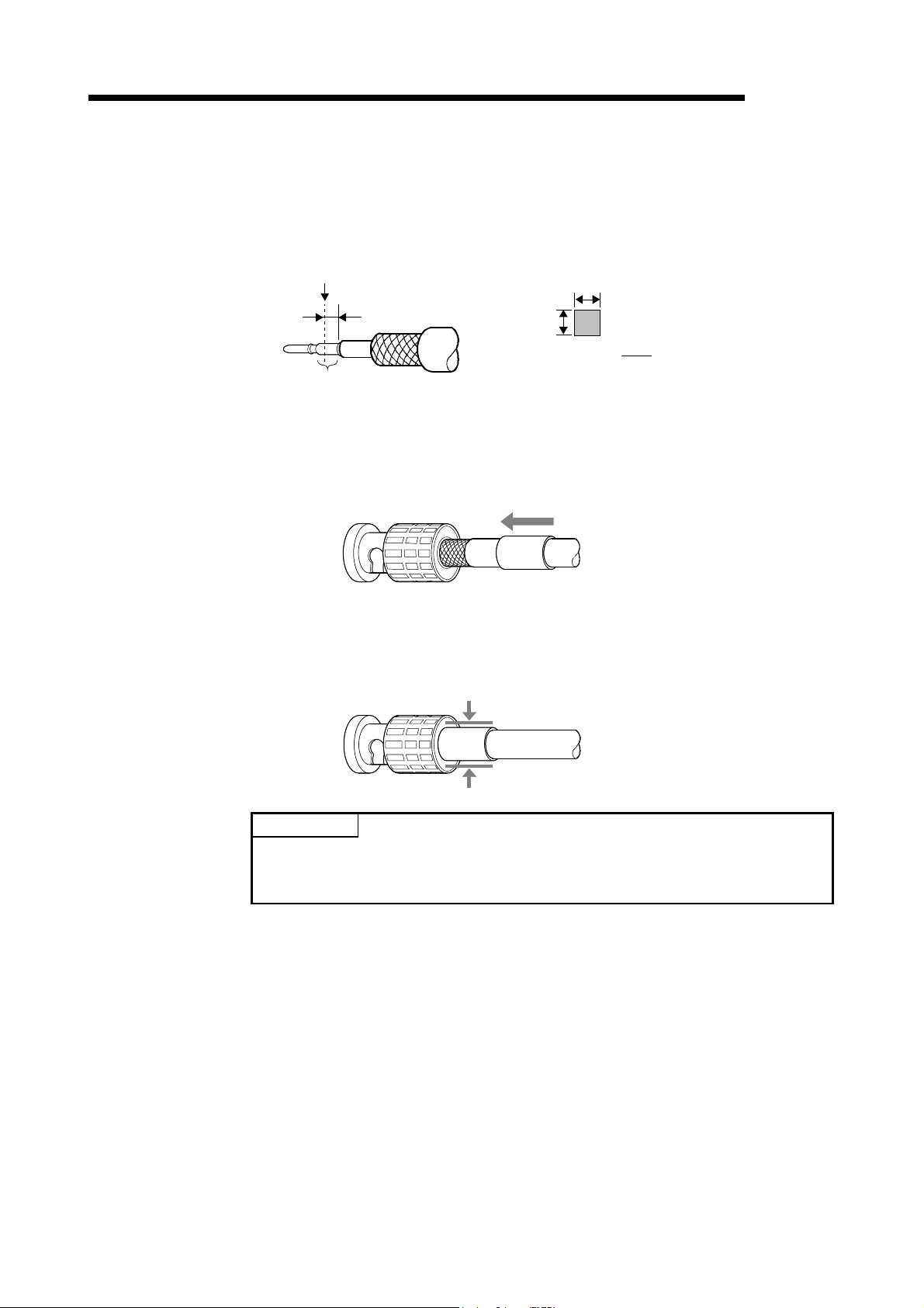
6 PROCEDURE AND SETTINGS UP TO THE POINT OF OPERATION
3) After the crimp, check the crimp height of the crimp part. When the
crimp height at the measurement position is between 1.4mm and
1.5mm, the pin is properly crimped.
If the crimp height is not between 1.4mm and 1.5mm, adjust the crimp
Measurement position of
crimp height
Crimp part
tool and crimp the center contact pin again.
Cross section of
the measurement position
A
1.5mm to 2.0mm
B
Crimp height value= mm
A+B
2
4) Hold the root of the coaxial cable and fully insert the cable into a plug.
After inserting the cable, pull it lightly to check that the center contact
pin is fixed.
Move the crimp sleeve until it contacts with the plug.
MELSEC
5) Crimp the crimp sleeve using the crimp tool with attention paid to the
orientations of the crimp tool and connector.
Do not pull the cable when crimping the sleeve.
Crimp
POINT
Before connecting or disconnecting the coaxial connector, touch a grounded metal
object to discharge the static electricity from the human body. Failure to do so may
result in a MELSECNET/H board malfunction.
6 - 22 6 - 22
Page 79
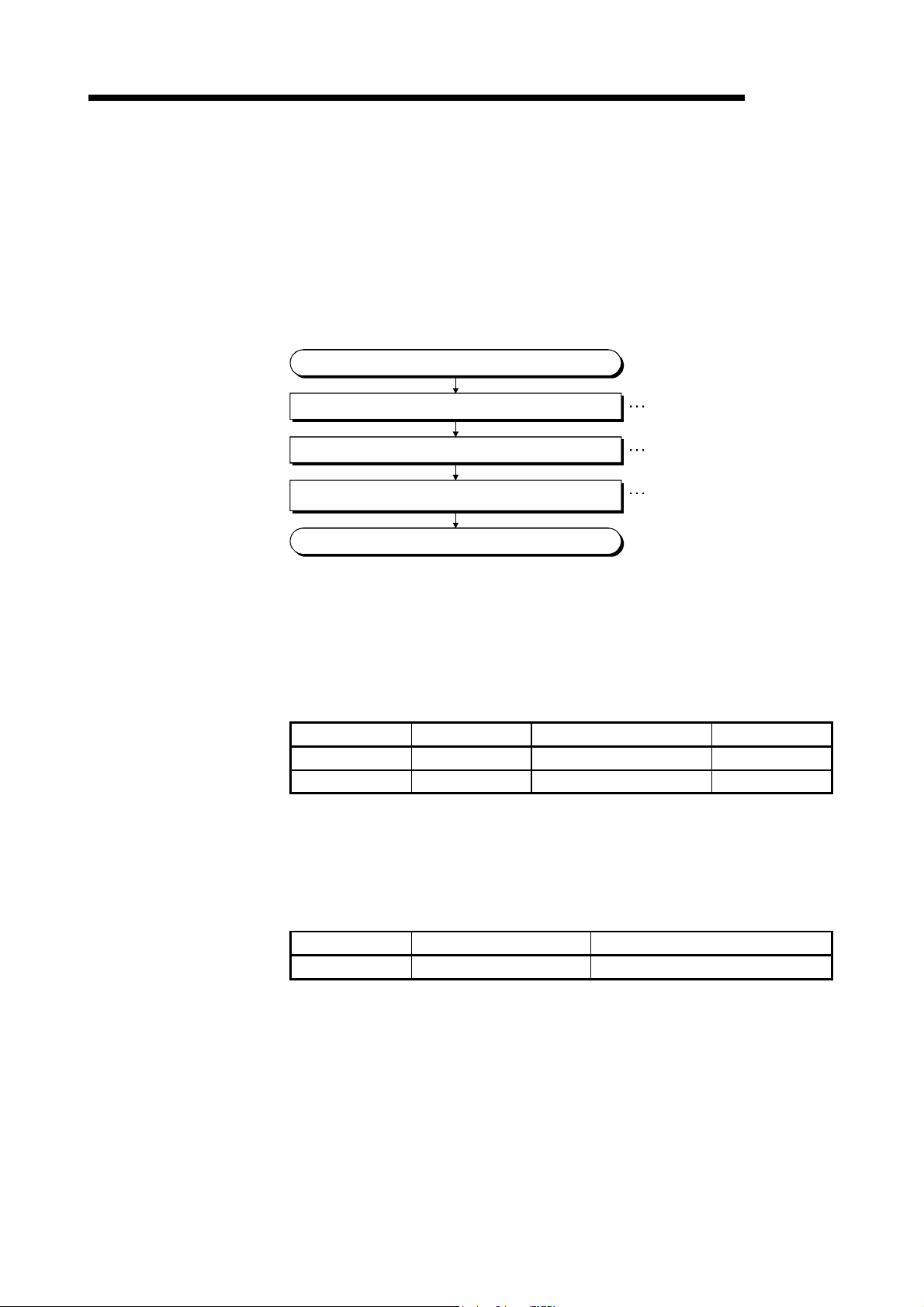
6 PROCEDURE AND SETTINGS UP TO THE POINT OF OPERATION
6.4.4 External power supply cable wiring
This section explains how to connect the external power supply cable to the Q80BDJ71LP21S-25.
(1) Connection steps
Connect the external power supply cable to the Q80BD-J71LP21S-25 in the
following steps:
Start
MELSEC
Check if necessary parts have been prepared.
Make an external power supply cable.
Connect the external power supply cable
to the Q80BD-J71LP21S-25.
End
Refer to (2) in this section
Refer to (3) in this section
Refer to (4) in this section
(2) Parts and tool required for making an external power supply cable
To make an external power supply cable, the following parts and a tool are
required.
(a) Connector set (Accessory)
Check that the following parts are contained in the connector set supplied
with the product.
Parts Model Applicable cable size Quantity
Connector 1-178288-3 ---- 1
Contacting pin 175218-2 AWG#20-16 3 (1 spare)
(b) Cable
Use an external power supply cable with heat-resistant vinyl sheath of 0.50
to 1.25mm
2
[AWG#20-16].
(c) Tool
Be sure to use the following specified tool.
Model Applicable cable size Inquiry
91558-1 AWG#20-16 Tyco Electronics
6 - 23 6 - 23
Page 80

6 PROCEDURE AND SETTINGS UP TO THE POINT OF OPERATION
(3) Making external power supply cable
Make an external power supply cable as follows:
(a) Crimping to the contacting pin
Using a crimping tool, crimp the cable and contacting pin.
Set the contacting pin and cable in the grooves of the crimping tool and
squeeze the handle tightly.
For details, refer to the instructions of the crimping tool.
(b) Check the crimped condition
Check if the cable (including a part
of the sheath) is evenly crimped to
the contacting pin.
If only wire part is crimped and not
the sheath part, or if the cable is
stuck out, the cable can be cut off or
malfunction may occur.
MELSEC
Contacting pin
Cable
(c) Connecting to the connector
According to the following pin
Connector
123
assignment, fully insert the crimped
cable to the connector until a click
is heard.
Pin No. Description
1 24V
2 24G
3 Open
Contacting pin
24V
24G
(4) Connecting external power supply cable to board
Properly insert the completed external power supply cable to the external power
supply cable connector of the Q80BD-J71LP21S-25 until a click is heard.
Keep the external power supply cable away from the main circuit cable, power
cables and/or load cables connected to other than programmable controllers.
(Ensure a distance of 100mm (3.94 in.) between them.)
POINT
Be sure to twist the external power supply cable.
6 - 24 6 - 24
Page 81

6 PROCEDURE AND SETTINGS UP TO THE POINT OF OPERATION
MELSEC
6.5 Test
Before executing the data link operation, check the MELSECNET/H board and the
cables.
Select a test item using the mode setting switch on the "Board information" screen in
the MNETH Utility.
Item Test type Description Reference
Board
confirmation
Network
confirmation
Self-loopback test
Internal self-loopback test
Hardware test
Test between master station
Test between slave station
Forward loop test
Reverse loop test
The MELSECNET/H board test has the following five types.
This test checks the hardware of the internal circuits,
including the send/receive circuit of the MELSECNET/H
board, as well as the cables.
This test checks the hardware of the internal circuits,
including the send/receive circuit of the MELSECNET/H
board.
This test checks the hardware inside the MELSECNET/H
board.
This test checks the hardware of the MELSECNET/H
board, network modules and cables between two adjacent
stations can be checked.
This test checks the Q80BD-J71LP21-25, Q81BD-
J71LP21-25, Q80BD-J71LP21S-25, Q80BD-J71LP21G,
Q80BD-J71LP21GE network module and cable hardware
after all the stations have been connected with optical fiber
cable, and can also check if the IN and OUT cables have
been connected correctly.
Section 6.5.1
Section 6.5.2
Section 6.5.3
Section 6.5.4
Section 6.5.5
REMARK
The test modes are equivalent to offline. The data link cannot be executed if one
station is set to the test mode during data link. Set the mode to "Online (auto.
reconnection)" when performing data link.
6 - 25 6 - 25
Page 82

6 PROCEDURE AND SETTINGS UP TO THE POINT OF OPERATION
6.5.1 Self-loopback test
In this section, a check of the hardware, including the MELSECNET/H board itself, the
transmission and reception lines in the transmission system and the cable, is
conducted.
(1) Connect optical fiber cables to the IN and OUT connectors of the Q80BD-
J71LP21-25, Q81BD-J71LP21-25, Q80BD-J71LP21S-25, Q80BD-J71LP21G
and Q80BD-J71LP21GE.
In the case of the Q80BD-J71BR11 (for the coaxial bus system), connect
terminal resistors to the two Type F connectors.
MELSEC
(2) Set the mode setting in the "Board Information" screen of the MNETH Utility on
"Self-loopback test. "
6 - 26 6 - 26
Page 83

6 PROCEDURE AND SETTINGS UP TO THE POINT OF OPERATION
(3) Click the Board Set
utility to run the self-loopback test, checking the LED status in the "Board
Information" screen to confirm the execution state.
T. PASS blinks during the test.
If T. PASS blinks 20 times and ERROR LED does not blink, the test is completed
normally.
Also, if the test ends abnormally, the ERROR LED will blink as shown below to
indicate the relevant error information.
(a) Optical Loop System
(Q80BD-J71LP21-25, Q81BD-J71LP21-25, Q80BD-J71LP21S-25, Q80BDJ71LP21G, Q80BD-J71LP21GE)
1) "TIME" LED lights up
• The forward loop cable is broken.
• The forward loop's transmission side and reception side cables are
not connected.
2) "DATA" LED lights up
• The reverse loop cable is broken.
• The reverse loop's transmission side and reception side cables are
not connected.
3) The "CRC", "OVER" and "AB.IF" LEDs light up on the F.LOOP and
R.LOOP sides
• The cable is defective.
4) "UNDER" LED lights up
• Hardware error.
• The cable was disconnected during the test.
• The cable was broken during the test.
(b) Coaxial Bus System (Q80BD-J71BR11)
1) "TIME" LED lights up
• The connector is disconnected.
2) The "CRC", "OVER" and "AB.IF" LEDs light up on the F.LOOP and
R.LOOP sides
• The connector is defective.
3) "DATA" and "UNDER" LED lights up
• Hardware error.
• The connector was disconnected during the test.
(4) Corrective action when the test completes abnormally
Check if the cable failure is not occurred, the connector is not disconnected, and
the wiring is appropriate. If there is any error, correct the connection.
When the cable has been disconnected, replace the cable.
When the hardware error has occurred, replace the board.
button in the "Board Information" screen of the MNETH
MELSEC
6 - 27 6 - 27
Page 84

6 PROCEDURE AND SETTINGS UP TO THE POINT OF OPERATION
6.5.2 Internal self-loopback test
In this section, a check of the hardware, including the transmission and reception lines
in the transmission on the MELSECNET/H board itself, is conducted.
(1) Optical fiber cables are not connected to the Q80BD-J71LP21-25, Q81BD-
J71LP21-25, Q80BD-J71LP21S-25, Q80BD-J71LP21G and Q80BD-J71LP21GE
(for the optical loop system). However, be careful that no external light enters
from outside the connectors.
In the case of the Q80BD-J71BR11 (for the coaxial bus system), do not connect
terminal resistors to the two Type F connectors.
MELSEC
(2) Set the mode setting in the "Board Information" screen of the MNETH utility on
"Internal self-loopback test."
6 - 28 6 - 28
Page 85

6 PROCEDURE AND SETTINGS UP TO THE POINT OF OPERATION
(3) Click the
utility to run the Internal self-loopback test, checking the LED status in the "Board
Information" screen to confirm the execution state.
T. PASS blinks during the test.
If T. PASS blinks 20 times and ERROR LED does not blink, the test is completed
normally.
Also, if the test ends abnormally, the ERROR LED will blink as shown below to
indicate the relevant error information.
(a) Optical Loop System
(b) Coaxial Bus System (Q80BD-J71BR11)
(4) Corrective action when the test completes abnormally
Replace the MELSECNET/H board.
Board Set button in the "Board Information screen of the MNETH
(Q80BD-J71LP21-25, Q81BD-J71LP21-25, Q80BD-J71LP21S-25, Q80BDJ71LP21G, Q80BD-J71LP21GE)
1) The "CRC", "OVER", "AB.IF", "TIME", "DATA" and "UNDER" LEDs
light up.
• Hardware error.
2) The "CRC", "OVER", "AB.IF", "TIME", "DATA" and "UNDER" LEDs
light up.
• Hardware error.
MELSEC
REMARK
If an error occurs in the coaxial bus system, the "M/S.E" LED or "PRM.E" LED may
light up besides the "CRC", "OVER", "AB.IF", "TIME", "DATA" and "UNDER" LEDs
lighting up.
When requesting repairs of the MELSECNET/H board, be sure to inform the service
technician of the LED lighting state.
6 - 29 6 - 29
Page 86

6 PROCEDURE AND SETTINGS UP TO THE POINT OF OPERATION
6.5.3 H/W test
MELSEC
This test checks the internal hardware on the MELSECNET/H board.
(1) Connect the optical fiber cables to the IN and OUT sides of the Q80BD-J71LP21-
25, Q81BD-J71LP21-25, Q80BD-J71LP21S-25, Q80BD-J71LP21G and Q80BDJ71LP21GE (for the optical loop system).
In the case of the Q80BD-J71BR11 (for the coaxial bus system), do not connect
a Type F connector or any terminal resistors.
(2) Set the "H/W test" in the mode settings in the "Board Information" screen of the
MNETH utility.
(3) Click the Board Set
utility to run the H/W test, and check the execution state by the status of the
LED's in the "Board Information" screen.
T. PASS blinks during the test.
If T. PASS blinks 20 times and ERROR LED does not blink, the test is completed
normally.
Also, if the test ends abnormally, the ERROR LED will blink as shown below to
indicate the relevant error information.
(a) Both the optical loop system (Q80BD-J71LP21-25, Q81BD-J71LP21-25,
Q80BD-J71LP21S-25, Q80BD-J71LP21G, Q80BD-J71LP21GE) and the
coaxial bus system (Q80BD-J71BR11) in common
If the following LED's light up, it means that the corresponding error has
occurred, so replace the MELSECNET/H board.
1. "CRC" LED lights up ·······ROM Check Error
2. "OVER" LED lights up ······RAM Check Error
3. "AB.IF" LED lights up ·······Timer, interrupt function check error
(b) Optical loop system (Q80BD-J71LP21-25, Q81BD-J71LP21-25, Q80BD-
J71LP21S-25, Q80BD-J71LP21G, Q80BD-J71LP21GE) only
1. "TIME" LED lights up ·······Forward loop broken line check error
2. "DATA" LED lights up ······Reverse loop broken line check error
(4) Corrective action when the test completes abnormally
Replace the MELSECNET/H board
button in the "Board Information" screen in the MNETH
6 - 30 6 - 30
Page 87

r
6 PROCEDURE AND SETTINGS UP TO THE POINT OF OPERATION
6.5.4 Station to station test
In the station to station test, the hardware of the MELSECNET/H board, network
modules and cables between two adjacent stations can be checked.
The following explains how to conduct the station to station test:
REMARK
This section explains concerning the MELSECNET/H board.
Refer to the following manuals concerning network module settings.
• Q corresponding MELSECNET/H Network System Reference Manual (PLC to
PLC network)
• QnA/Q4AR Corresponding MELSECNET/10 Network System Reference Manual
(1) Connecting the cable
(a) Optical loop system
Connect IN and OUT of network modules, Q80BD-J71LP21-25, Q81BDJ71LP21-25, Q80BD-J71LP21S-25, Q80BD-J71LP21G or Q80BDJ71LP21GE with an optical fiber cable.
Station to
execute test
Station to
be tested
MELSEC
Station
No. n
Side
IN
OUT
Station
No. n+1
Side
OUT
Optical fiber cable
IN
(b) Coaxial bus system
Connect network modules or Q80BD-J71BR11 with a coaxial cable.
Station to
execute test
Station
No. n
Side
Terminal
resisto
Station to
be tested
Station
No. n+1
Side
Coaxial cable
Terminal
resistor
6 - 31 6 - 31
Page 88

6 PROCEDURE AND SETTINGS UP TO THE POINT OF OPERATION
REMARK
Before conducting the station to station test when three or more stations are
connected by the coaxial bus system, any stations that are not tested should be
switched to offline or powered off.
Station to
execute test
Station to
be tested
Offline or
powered off
(2) Test mode settings
In the mode settings in the MNETH utility's "Board Information" screen, set the
Station No. n, Station No. n + 1 stations' respective "Test between master
station" and "Test between slave station" settings.
(3) Start of inter-station test
Set the mode setting on "Test between master station" or "Test between slave
station" and click the Board Set
button.
MELSEC
This operation is performed in the order of control station
normal station.
6 - 32 6 - 32
Page 89

6 PROCEDURE AND SETTINGS UP TO THE POINT OF OPERATION
(4) Click the Board Set
utility to run the station to station test, checking the LED status in the "Board
Information" screen to confirm the execution state.
If T. PASS blinks 20 times and ERROR LED does not blink, the test is completed
normally.
Also, if the test ends abnormally, the following ERROR LED or L. ERR. LED will
blink as shown below to indicate the relevant error information.
(a) Optical Loop System
(Q80BD-J71LP21-25, Q81BD-J71LP21-25, Q80BD-J71LP21S-25, Q80BDJ71LP21G, Q80BD-J71LP21GE)
1) "TIME" LED lights up
• The forward loop cable is broken.
• The forward loop's transmission side and reception side cables are
not connected.
2) "DATA" LED lights up
• The reverse loop cable is broken.
• The reverse loop's transmission side and reception side cables are
not connected.
3) The "CRC", "OVER" and "AB.IF" LEDs light up on the F.LOOP and
R.LOOP sides
• The cable is defective.
4) "UNDER" LED lights up
• Hardware error.
• The cable was disconnected during the test.
• The cable was broken during the test.
(b) Coaxial Bus System (Q80BD-J71BR11)
1) "TIME" LED lights up
• The connector is disconnected.
2) The "CRC", "OVER" and "AB.IF" LEDs light up on the F.LOOP and
R.LOOP sides
• The connector is defective.
3) "DATA" and "UNDER" LED lights up
• Hardware error.
• The connector was disconnected during the test.
(5) Corrective action when the test completes abnormally
Check if the cable failure is not occurred, the connector is not disconnected, and
the wiring is appropriate. If there is any error, correct the connection.
When the cable has been disconnected, replace the cable.
When the hardware error has occurred, replace the board.
For the error occurred in the other station, check the other station.
button in the "Board Information" screen of the MNETH
MELSEC
6 - 33 6 - 33
Page 90

6 PROCEDURE AND SETTINGS UP TO THE POINT OF OPERATION
6.5.5 Forward loop/Reverse loop test
Using the forward loop / reverse loop test you can check the Q80BD-J71LP21-25,
Q81BD-J71LP21-25, Q80BD-J71LP21S-25, Q80BD-J71LP21G, Q80BD-J71LP21GE
network module and cable hardware after all the stations have been connected with
optical fiber cable, and can also check if the IN and OUT cables have been connected
correctly.
POINT
The forward loop/reverse loop test can be used only when the Q80BD-J71LP21-25,
Q81BD-J71LP21-25, Q80BD-J71LP21S-25, Q80BD-J71LP21G or Q80BDJ71LP21GE is used as the control station. If it is a normal station, carry out the test
from the control station of the network where the normal station is connected.
REMARK
This section explains concerning the MELSECNET/H board.
Refer to the following manuals concerning network module settings.
• Q corresponding MELSECNET/H Network System Reference Manual (PLC to
PLC network)
• QnA/Q4AR Corresponding MELSECNET/10 Network System Reference Manual
(1) Test mode settings
If you are performing the forward loop test, set the station executing the forward
loop test on "Forward loop test" in the mode settings in the "Board Information"
screen of the MNETH utility.
Also, for stations other than the station where the test is being run, treat them as
Online.
If you are performing the reverse loop test, set the station executing the forward
loop test on "Reverse loop test" in the mode settings in the "Board Information"
screen of the MNETH utility.
(2) Start of the test
Set the mode setting on "Forward loop test," "Reverse loop test" or "Online", then
click the Board Set
This operation is performed in the order of control station
button.
MELSEC
normal station.
6 - 34 6 - 34
Page 91

6 PROCEDURE AND SETTINGS UP TO THE POINT OF OPERATION
(3) Checking the test results
Click the Board Set button in the "Board Information" screen in the MNETH
utility to run the forward loop/reverse loop test, and check the execution state by
the status of the LED's in the "Board Information" screen.
If T. PASS blinks 20 times and ERROR LED does not blink, the test is completed
normally.
Also, if the test ends abnormally, the ERROR LED or the L.ERR.LED will blink as
shown below to indicate the relevant error information.
1) The "TIME," "DATA" and "UNDER" LED's blink on the F.LOOP and
R.LOOP sides.
• The cable or the other station is abnormal and loop back occurred.
2) The "CRC", "OVER" and "AB.IF" LED's blink on the F.LOOP and R.LOOP
sides.
• The cable is defective.
3) The "TIME" and "DATA" LED's blink on the F.LOOP and R.LOOP sides.
• The wiring is wrong.
Check and correct the cable connections before and after the station
where the error occurred.
(4) Corrective action when the test completes abnormally
Check if the cable failure is not occurred, the connector is not disconnected, and
the wiring is appropriate. If there is any error, correct the connection.
When the cable has been disconnected, replace the cable.
For the error occurred in the other station, check the other station.
MELSEC
6 - 35 6 - 35
Page 92

6 PROCEDURE AND SETTINGS UP TO THE POINT OF OPERATION
MEMO
MELSEC
6 - 36 6 - 36
Page 93

7 PARAMETER SETTINGS
MELSEC
7 PARAMETER SETTINGS
It is necessary to set the MELSECNET/H board's parameters using the MNETH utility
in order to operate the MELSECNET/H.
In setting of the parameters, after the MELSECNET/H is selected, it can be set even to
the details of the application functions.
A flow chart of the settings is shown below.
Board information settings
1) Channel···············MELSECNET/H (1st board to 4th board)
2) Network type·······MNET/H mode, MNET/H EX mode,
Netw ork se ttings
1) Network No.·············1 to 239
2) Station No.···············1 to 6 4 (Op tical loop),
3) Control station / Normal station settings
Set the following items as necessary.
4) Group No.················1 to 3 2
No
Common parameters
1) Transmission range of each station
(LB/LW, LX/LY settings)
2) Total number of link stations
Set the following items as necessary.
3) I/O master station setting
4) Reserved station setting
Supplementary settings
Control station return setting
MNET/10 mode
1to32(Coaxialbus)
Control station?
Yes
Transmitting the common parameters to the MELSECNET/
H board.
7
Set the following functions
as necessary.
Not
necessary
Opposite party setting (when accessing a multiple
CPU system or redundant CPU system)
Routing parameter setting/transmission
MELSECNET/H board information update
Connection of cables
POINT
Necessary
··········Refer to Section 6.4.
When replacing a board, you may need the channel numbers and parameter
settings that were used before the replacement. When reinstalling the software
package, you need to reset the channel numbers and the parameter settings. Be
sure to record channel numbers and parameter settings when you have set
parameters.
7 - 1 7 - 1
Page 94

7 PARAMETER SETTINGS
REMARK
7.1 Board Information Settings
Data links can be executed even if the parameters are not set.
In that case, the MELSECNET/H board operates with the default state displayed in
the "Board Information" screen for the channel, network type, network No., station
No., control station/normal station settings and group No.
When the network type of the control station is the MELSECNET/H Extended mode,
the following condition occurs in a normal station with no parameters set.
In the case of a programmable controller: LINK PARA ERROR occurs.
In the case of a MELSECNET/H board: "L.ERR." LED lights up.
In such a case, set parameters to the normal station.
MELSEC
7
This sets the channel and network type for the MELSECNET/H board that is being
used. Perform the settings in the "Board Information" screen of the MNETH utility.
(1) Channel
Select the MELSECNET/H board for which settings are performed in the MNETH
utility.
A maximum of 4 MELSECNET/H boards can be installed in one personal
computer. The channels that are assigned to each MELSECNET/H board can be
checked by clicking the Channel No. Confirm
screen.
button in the "Board List"
(2) Network type
The settings in the mode for the network system where the MELSECNET/H
board is connected can be changed.
Item Corresponding network
MNET/H mode, MNET/H EX mode MELSECNET/H
MNET/10 mode MELSECNET/10
(3) Precautions
(a) Set an identical network type for stations within the same network.
If any different network type is included, the system does not operate
normally.
(b) For the MELSECNET/H Extended mode, use the MELSECNET/H board of
ROM version 2X or later and the SW0DNC-MNETH-B of version 11M or
later. When a MELSECNET/H board incompatible with the
MELSECNET/H Extended mode is used, the system does not operate
normally.
(c) When connecting a QnA or A series MELSECNET/10 network module, use
it in the MELSECNET/10 mode.
If used in any other mode, the system does not operate normally.
(d) Set a transmission speed matched with that of the network.
When an incorrect transmission speed is set, the system does not operate
normally.
7 - 2 7 - 2
Page 95

7 PARAMETER SETTINGS
7.2 Network Settings
These are the parameters used to build the MELSECNET/H network.
The MELSECNET/H board’s network No., station No., control station/normal station
setting and group No. are set.
7.2.1 Network No.
Set the Network No. of the network which the MELSECNET/H board is connected to.
To set the network No, set it in the "Board Information" screen in the MNETH utility.
(1) Valid setting range
1 to 239
(2) Caution
(a) Set the same network No. to all of the devices connected to the same
Network
No.2
network.
2NS1
Network
No.1
CPU QJ71
1M
MELSEC
Network
No.1
CPU QJ71 QJ71
2
P
1NS31NS4
Network
No.1
7.2.2 Station No.
Set the station No. of the MELSECNET/H board.
Set the station No. in the "Board Information" screen of the MNETH utility.
(1) Effective setting range
The effective setting range differs depending on the type of network.
• Optical loop system··········1 to 64
• Coaxial bus system··········1 to 32
(2) Caution
(a) Make settings so that the same station No. does not exist in more than one
place in the same network.
7.2.3 Control station/Normal station
Set the Control station / Normal station setting on the MELSECNET/H board.
Set the Control station / Normal station setting in the "Board Information" screen of the
MNETH utility.
7 - 3 7 - 3
Page 96

7 PARAMETER SETTINGS
7.2.4 Group No.
This sets the MELSECNET/H board's group No.
Set the group No. setting in the "Board Information" screen of the MNETH utility.
(1) Valid setting range
0: No group setting
1 to 9: When in the MELSECNET/10 Mode
1 to 32: When in the MELSECNET/H Mode and MELSECNET/H Extended Mode
(2) Cautions
(a) Only one Group No. can be set for 1 station.
Group No. 1 Group No. 2
MELSEC
7.2.5 Mode setting
Selection item Content
Online (auto. reconnection)
Offline
Forward loop test
Reverse loop test
Test between master station
Test between slave station
Self-loopback test
Internal self-loopback test
H/W test
Personal
computer
CPU
MP1
N
8
S
CPU
CPU
N
2
S
N
7
S
This sets the MELSECNET/H board's operating mode.
Normal operation (return to system) is selected.
When the system is started up, data communications is started and automatic return to
system operations, etc. are carried out.
Operation stop (disconnecting the station) is selected.
Handshake and data communications with other stations is not done.
The connection state with the forward loop side's optical fiber cable is checked. The
hardware test operation is selected.
For details, refer to section 6.5.5, "Forward loop / Reverse loop test."
The connection state with the reverse loop side's optical fiber cable is checked. The
hardware test operation is selected.
For details, refer to section 6.5.5, "Forward loop / Reverse loop test."
Selects the control station side for performing the hardware test for checking the lines
between two stations. For details, refer to section 6.5.4, "Station to station test."
Selects the normal station side for performing the hardware test for checking the lines
between two stations. For details, refer to section 6.5.4, "Station to station test."
Selects a hardware test of the MELSECNET/H board itself with the connection cables.
For details, refer to section 6.5.1, "Self-loopback test."
Selects a hardware test of the MELSECNET/H board itself.
For details, refer to section 6.5.2, "Internal self-loopback test."
Selects the internal hardware test for the MELSECNET/H board itself.
For details, refer to section 6.5.3, "H/W test."
CPU
Personal
computer
N
NS6
CPU
CPU
N
4
S
N
5
S
3
S
7 - 4 7 - 4
Page 97

7 PARAMETER SETTINGS
7.2.6 Parameter setting example
An example of setting the MELSECNET/H board parameters is shown below.
(1) System example
Control Station
(1Mp1) Port No. 51
MELSECNET/H (25 Mbps)
Network No. 1
MELSEC
to
1Ns81Ns2
(2) Setting screen (Board information screen)
7 - 5 7 - 5
Page 98

7 PARAMETER SETTINGS
7.3 Common Parameters
The common parameters are used to set the cyclic transmission ranges of LB, LW, LX
and LY that can be sent by each station in a single network. The common parameter
settings are required only for the control station. The data of the common parameters
are sent to the normal stations when the network starts up.
7.3.1 Send range for each station (LB/LW settings)
Assign the send ranges of the link devices (LB/LW) for each station in 16 point units for
LB (start
0 to end
F) and in one point unit for LW.
The following example shows send range for each station (LB/LW settings) when each
of 512 points is assigned to station numbers 1 to 8.
(1) Setting example
1MP1
1NS2 1NS3
MELSEC
1NS4
Network No. 1
1NS51NS61NS71NS8
Send range
for each station
0
to
1FF
200
to
3FF
400
to
5FF
600
to
7FF
800
to
9FF
A00
to
BFF
C00
to
DFF
E00
to
FFF
3FFF
1MP1
1NS2
1N
S
S4
1N
S5
1N
1N
S
1N
S
S8
1N
1N
1M
P1
Host's
send range
1NS2
3
6
7
1N
1N
1N
1N
1N
1N
3
S
S4
S5
6
S
7
S
S8
1NS2
1M
1
P
Host's
send range
3
1N
S
S4
1N
S5
1N
6
1N
S
7
1N
S
S8
1N
3
S
1M
1
P
1NS2
Host's
send range
S4
1N
S5
1N
6
1N
S
7
1N
S
S8
1N
1N
S8
1M
1
P
1NS2
3
1N
S
S4
1N
S5
1N
6
1N
S
7
1N
S
Host's
send range
7 - 6 7 - 6
Page 99

7 PARAMETER SETTINGS
(2) Screen settings (Common parameter setting screen)
Perform the setting of each station's transmission range (LB/LW settings) in the
"Common parameter setting" screen in the MNETH utility.
MELSEC
POINT
In order to validate the guarantee of 32-bit data, it is necessary that the number of
points in each station's transmission range be a multiple of 20
multiple of 2 for LW and that each station's top device No. be set so that the LB is a
multiple of 20
data, refer to the "Q Corresponding MELSECNET/H Network System Reference
Manual (PLC to PLC Network)".)
H for LB and a
H and the LW is a multiple of 2. (For details on guaranteeing 32-bit
7 - 7 7 - 7
Page 100

7 PARAMETER SETTINGS
7.3.2 Send range for each station (LX/LY settings)
Set send ranges for each station of LX/LY, which represent the amount of data that
can be sent by each station in a single network in one (two) block units.
The link devices (LX/LY) between the I/O master station (M station) and other station
(L station) are assigned 1:1.
The following example shows send ranges for each station (LX/LY settings) when each
of 512 points of link devices (LX/LY) is assigned to station numbers 2 to 4, using
station number 1 (host) as the I/O master station of block 1.
(1) Setting example
Block 1
MELSEC
1MP11N
X0
X1000
to
X11FF
X1200
to
X13FF
X1400
to
X15FF
X1FFF Y1FFF
I/O master station
(MNELSECNET/H board)
1MP1
(M station)
Y0
Y1000
to
Y11FF
Y1200
to
Y13FF
Y1400
to
Y15FF
X
21N
S
Y
Actual I/O Actual I/O
1NS2
(L station)
X
31N
S
1NS3
(L station)
Network No. 1
4 1NS8
X
Y
S
Actual I/O
1NS4
(L station)
Y
X
Actual I/O
1NS8
Y
7 - 8 7 - 8
 Loading...