

Mitsubishi Electric Q80BD-J71GP21-SX, Q80BD-J71GP21S-SX, Q81BD-J71GP21-SX, Q81BD-J71GP21S-SX User Manual
Page 1
CC-Link IE Controller Network Interface Board
User's Manual (For SW1DNC-MNETG-B)
-Q80BD-J71GP21-SX
-Q80BD-J71GP21S-SX
-Q81BD-J71GP21-SX
-Q81BD-J71GP21S-SX
Page 2

Page 3
SAFETY PRECAUTIONS
WARNING
CAUTION
Indicates that incorrect handling may cause hazardous conditions,
resulting in death or severe injury.
Indicates that incorrect handling may cause hazardous conditions,
resulting in minor or moderate injury or property damage.
(Be sure to read these instructions before using the product.)
Before using this product, read this manual and the relevant manuals introduced in this manual carefully
and handle the product correctly with full attention to safety.
Note that these precautions apply only to this product. Refer to the user's manual of your CPU module for
safety precautions on programmable controller systems.
In this manual, the safety instructions are ranked as " WARNING" and " CAUTION".
Note that failure to observe the CAUTION level instructions may also lead to serious results depending on the
circumstances.
Be sure to observe the instructions of both levels to ensure personal safety.
Please store this manual in a safe place for future reference. This manual must be forwarded to the end user.
A - 1
Page 4
[Design Precautions]
WARNING
Configure safety circuits external to the programmable controller to ensure that the entire system
operates safely even when a fault occurs in a personal computer. Failure to do so may result in an
accident due to an incorrect output or malfunction.
(1) Emergency stop circuits, protection circuits, and protective interlock circuits for conflicting
operations (such as forward/reverse rotations or upper/lower limit positioning) must be
configured external to the programmable controller.
(2) The station to which the board is installed may be disconnected from the data link due to a data
link error. If this occurs, the data output from the station and written to other stations before the
error will be held until the station is reconnected to the network (until its data link is restarted).
Provide a mechanism for data link status monitoring and error handling for each station that is
connected to the data link system.
For the operating status of each station after a communication failure, refer to CC-Link IE Controller
Network Reference Manual for each network. Incorrect output or malfunction due to a
communication failure may result in an accident.
When changing data during operation, configure an interlock circuit in the program to ensure that the
entire system will always operate safely. Configure an interlock circuit in the program, and determine
corrective actions to be taken between the external device and CPU module in case of a
communication failure.
Laser diodes are used in the optical transceivers of the CC-Link IE Controller Network. The laser
class (IEC 60825-1) of these laser diodes is Class 1. Do not look directly at laser light. Doing so may
harm your eyes.
CAUTION
Do not install the external power supply or communication cables together with the main circuit lines
or power cables. Keep a distance of 100mm (3.94 in.) or more between them. Failure to do so may
result in malfunction due to noise.
[Installation Precautions]
WARNING
Shut off the external power supply for the system in all phases before installing the board to or
removing it from the personal computer.
Failure to do so may result in electric shock or cause the board to fail or malfunction.
Do not touch any connectors while power is on. Doing so may cause electric shock or malfunction.
A - 2
Page 5

CAUTION
Use the board in an environment that meets the general specifications in this manual.
Failure to do so may result in electric shock, fire, malfunction, or damage to or deterioration of the
product.
Do not directly touch any conductive parts and electronic components of the board.
Doing so may cause malfunction or failure of the board.
When installing the board, take care not to get injured by an implemented component or a
surrounding member.
Fix the board by tighten the board-fixing screws within the specified torque range.
Undertightening may cause drop of the component or wire, short circuit, or malfunction.
Overtightening may damage the screw and/or module, resulting in drop, short circuit, or malfunction.
For the tightening torque of the board-fixing screws, refer to the manual supplied with the personal
computer.
Before handling the board, touch a conducting object such as a grounded metal to discharge the static
electricity from the human body.
Failure to do so may cause the board to fail or malfunction.
Install the board to a personal computer which is compliant with PCI standard or PCI Express
standard (Section 2.5 Operating Environment). Failure to do so may cause a failure or
malfunction.
Securely insert the board into the PCI slot following the board installation instruction of the personal
computer.
Incorrect insertion of the board may lead to a malfunction, failure or drop of the board.
When installing the board, take care not to get injured by an implemented component or a
surrounding member.
When installing the board, take care not to contact with other boards.
Handle the board in a place where static electricity will not be generated.
Failure to do so may cause a failure or malfunction.
The board is included in an antistatic envelope.
When storing or transporting it, be sure to put it in the antistatic envelope.
Failure to do so may cause a failure or malfunction.
Do not drop or apply a strong impact to the board.
Doing so may cause a failure or malfunction.
®
A - 3
Page 6
[Wiring Precautions]
WARNING
Shut off the external power supply for the system in all phases before installing the board or starting
wiring.
Failure to do so may result in electric shock, damage to the product, or malfunction.
After installation of the board and wiring, attach the cover on the module before turning it on for
operation.
Failure to do so may result in electric shock.
CAUTION
Check the rated voltage and pin-out before wiring to the external power supply cable, and connect
the cables correctly.
Connecting a power supply with a different voltage rating or incorrect wiring may cause a fire or
failure.
Place the communication cable and the external power supply cable connected to the board in a
duct or clamp them.
If not, dangling cables may swing or inadvertently be pulled, resulting in damage to the board or
cables or malfunctions due to poor contact.
When disconnecting the cable from the board, do not pull the cable by the cable part.
Pulling the cable connected to the board may result in malfunction or damage to the board or cable.
Prevent foreign matter such as dust or wire chips from entering the personal computer.
Such foreign matter may cause a fire, failure, or malfunction.
Do not install the external power supply or communication cables together with the main circuit lines
or power cables.
Keep a distance of 100mm (3.94 in.) or more between them. Failure to do so may result in
malfunction due to noise.
Special skills and tools are required to connect the communication cable to the connector plug,
which is an exclusive product.
When purchasing it, please consult your local Mitsubishi representative.
Incomplete connection can result in a short, fire or malfunction.
Securely plug the communication cable to the connector of the board.
Then, check for any incomplete connection.
Poor contact may cause an erroneous input or output.
A - 4
Page 7
[Wiring Precautions]
CAUTION
Use a specified tool for crimping of the cable and contacting pin. Imperfect crimping may cause a
malfunction.
Verify the pin-out and fully insert the crimped contacting pin into the connector. Imperfect insertion
may cause a failure or malfunction.
Insert the wired external power supply cable into the external power supply cable connector until a
click is heard.
Imperfect insertion may cause a failure or malfunction.
Always ground the personal computer to the protective ground conductor.
Failure to do so may cause a malfunction.
[Startup/Maintenance Precautions]
WARNING
Shut off all phases of the external power supply before cleaning the board or retightening the fixing
screws. Failure to do so may result in an electric shock, or cause a failure or malfunction of the
board.
Shut off the external power supply for the system in all phases before installing the board to or
removing it from the personal computer.
Failure to do so may result in electric shock or cause the board to fail or malfunction.
Do not connect or disconnect any communication cable while power is on.
Doing so may result in a malfunction.
A - 5
Page 8
[Startup/Maintenance Precautions]
CAUTION
Thoroughly read the manual and ensure the safety before performing program modification during
operation, forced output, operation such as RUN, STOP and PAUSE.
An improper operation will result in mechanical damage or accidents.
Do not disassemble or modify the board.
Doing so may cause failure, malfunction, injury, or a fire.
Fix the board by tighten the board-fixing screws within the specified torque range. Undertightening
may cause drop of the component or wire, short circuit, or malfunction. Overtightening may damage
the screw and/or module, resulting in drop, short circuit, or malfunction.
For the tightening torque of the board-fixing screws, refer to the manual supplied with the personal
computer.
Before handling the board, touch a conducting object such as a grounded metal to discharge the
static electricity from the human body.
Failure to do so may cause the board to fail or malfunction.
The board is included in an antistatic envelope.
When storing or transporting it, be sure to put it in the antistatic envelope.
Failure to do so may cause a failure or malfunction.
The microprocessor built in the board will reach a high temperature during operation. Do not touch it
directly when replacing the board.
Doing so may result in a failure, malfunction or injury.
[Disposal Precautions]
CAUTION
When disposing of this product, treat it as industrial waste.
A - 6
Page 9

CONDITIONS OF USE FOR THE PRODUCT
(1) Mitsubishi programmable controller ("the PRODUCT") shall be used in conditions;
i) where any problem, fault or failure occurring in the PRODUCT, if any, shall not lead to any major
or serious accident; and
ii) where the backup and fail-safe function are systematically or automatically provided outside of
the PRODUCT for the case of any problem, fault or failure occurring in the PRODUCT.
(2) The PRODUCT has been designed and manufactured for the purpose of being used in general
industries.
MITSUBISHI SHALL HAVE NO RESPONSIBILITY OR LIABILITY (INCLUDING, BUT NOT
LIMITED TO ANY AND ALL RESPONSIBILITY OR LIABILITY BASED ON CONTRACT,
WARRANTY, TORT, PRODUCT LIABILITY) FOR ANY INJURY OR DEATH TO PERSONS OR
LOSS OR DAMAGE TO PROPERTY CAUSED BY the PRODUCT THAT ARE OPERATED OR
USED IN APPLICATION NOT INTENDED OR EXCLUDED BY INSTRUCTIONS, PRECAUTIONS,
OR WARNING CONTAINED IN MITSUBISHI'S USER, INSTRUCTION AND/OR SAFETY
MANUALS, TECHNICAL BULLETINS AND GUIDELINES FOR the PRODUCT.
("Prohibited Application")
Prohibited Applications include, but not limited to, the use of the PRODUCT in;
• Nuclear Power Plants and any other power plants operated by Power companies, and/or any
other cases in which the public could be affected if any problem or fault occurs in the PRODUCT.
• Railway companies or Public service purposes, and/or any other cases in which establishment of
a special quality assurance system is required by the Purchaser or End User.
• Aircraft or Aerospace, Medical applications, Train equipment, transport equipment such as
Elevator and Escalator, Incineration and Fuel devices, Vehicles, Manned transportation,
Equipment for Recreation and Amusement, and Safety devices, handling of Nuclear or
Hazardous Materials or Chemicals, Mining and Drilling, and/or other applications where there is a
significant risk of injury to the public or property.
Notwithstanding the above, restrictions Mitsubishi may in its sole discretion, authorize use of the
PRODUCT in one or more of the Prohibited Applications, provided that the usage of the PRODUCT
is limited only for the specific applications agreed to by Mitsubishi and provided further that no
special quality assurance or fail-safe, redundant or other safety features which exceed the general
specifications of the PRODUCTs are required. For details, please contact the Mitsubishi
representative in your region.
A - 7
Page 10
REVISIONS
Addition
Correction
Correction
Addition
*The manual number is given on the bottom left of the back cover.
Print Date *Manual Number Revision
APR., 2007 SH (NA)-080691ENG-A First edition
Section 8.1.2, Appendix 3
Oct., 2007 SH(NA)-080691ENG-B
Jan., 2008 SH(NA)-080691ENG-C
GENERIC TERMS AND ABBREVIATIONS,
Section 1.2, Section 1.3, Section 2.5, Chapter 5, Section 8.1.1, Section 8.1.3,
Section 8.2, Section 8.3, Section 9.2.1, Section 9.2.3, Section 10.2.1,
Section 10.2.3, Chapter 15, Section 16.2, Section 16.3.1, Appendix 4
Section 8.1.2 changed to Section 8.1.3.
"MELSECNET/G network system" (controller network) is changed to "CC-Link
IE Controller Network"
SAFETY PRECAUTIONS, PRECAUTIONS FOR USE, INTRODUCTION,
CONTENTS, MANUAL, HOW TO USE THIS MANUAL,
GENERIC TERMS AND ABBREVIATIONS, PACKING LIST, CHAPTER 1,
Section 1.1, Section 1.2, Section 1.3, Section 2.1, Section 2.2.2, Section 2.2.3,
Section 2.3, Section 2.3.2, Section 2.4, Section 2.5, Section 2.6, CHAPTER 3,
Section 3.1, Section 3.2, CHAPTER 4, Section 4.1, Section4.2, Section 4.2.1,
Section 5.1, CHAPTER 6, Section 6.1, Section 6.2, Section 6.2.1,
Section 6.2.2, Section 6.3, Section 6.4, Section 6.4.1, Section 6.5,
Section 6.5.1, Section 6.5.2, Section 6.5.3, Section 6.6, Section 6.6.1,
Section 6.6.2, CHAPTER 7, Section 7.1, Section 7.2, Section 7.3,
Section 7.3.3, Section 7.4, Section 7.5, Section 7.6, Section 7.7, Section 7.8,
Section 7.9, Section 8.1, Section 8.1.1, Section 8.1.2, Section 8.1.3,
Section 8.2, CHAPTER 9, Section 9.1, Section 9.1.1, Section 9.2,
Section 9.2.1, Section 9.2.2, Section 9.2.3, Section 9.2.4, Section 9.3,
Section 9.3.1, Section 9.3.2, Section9.3.3, Section 9.4, Section 9.4.1,
Section 9.4.6, Section 9.4.7, Section 9.4.8, Section 9.5.1, Section 9.5.3,
Section 9.5.4, Section 10.1.1, Section 10.2.1, Section 10.3, Section 10.4,
Section 10.5, CHAPTER 11, Section 11.1, Section 11.1.2, Section 11.2,
Section 12.1, Section 12.4, Section 12.5, Section 12.6, Section 12.7,
Section 12.8, Section 12.9, Section 13.1.1, Section 13.2, Section 13.2.1,
Section13.3, CHAPTER 14, Section 14.2, Section 14.2.1, Section14.2.2,
Section14.2.3, Section 14.3, CHAPTER 15, Section 16.2, Section 16.3,
Section 16.3.1, Section 16.4, Section 16.4.1, Section16.4.2, Section 16.4.3,
Section 16.4.4, Section 16.4.5, Section 16.4.6, Section 16.5.2, Section 16.5.3,
Section 16.5.4, Section 16.7, APPENDICES
Section 9.4.7
A - 8
Page 11
Print Date *Manual Number Revision
Addition
Correction
Correction
Correction
Addition
Correction
Addition
Correction
Deletion
Section 9.3.4
May., 2008 SH(NA)-080691ENG-D
Sep., 2008 SH(NA)-080691ENG-E
Oct., 2008 SH(NA)-080691ENG-F
Apr., 2009 SH (NA)-080691ENG-G
Section 2.5, Section 2.6, Section 6.5.1, Section 6.5.2, Section 6.5.3,
Section 6.6.1, Section 6.6.2, Section 7.1, Section 9.3.3, Section 9.4.1,
Appendix 6.2
Section 2.5, Section 3.2, Section 7.1, Section 9.3.1, Section 9.4.1,
Appendix 6.1
PRECAUTIONS FOR USE, GENERIC TERMS AND ABBREVIATIONS,
Section 2.5, Section 9.4.6, Section 9.4.7, Section 11.1.2
Section 7.10, Section 9.4.9, Section 16.8
SAFETY PRECAUTIONS, GENERIC TERMS AND ABBREVIATIONS,
Section 2.2.2, Section 2.3.2, Section 4.2.1, CHAPTER 5, Section 6.5.1,
Section 6.5.2, Section 6.5.3, Section 6.6.1, Section 6.6.2, CHAPTER 7,
Section 7.1, Section 7.2, Section 7.5, Section 7.6, Section 7.7, Section 8.1.1,
Section 8.1.3, Section 8.2, Section 8.3, Section 9.1.1, Section 9.2,
Section 9.3.1, Section 9.3.3, Section 9.4.1, Section 9.4.6, Section 11.1.1,
Section 11.1.2, Section 12.2, Section 12.6, Section 12.7, Section 14.3,
CHAPTER 15, Section 16.4.3, Appendix 5.6, Appendix 6.1, Appendix 6.2,
Appendix 6.4
Sep., 2009 SH (NA)-080691ENG-H
Section 6.7, Section 14.1.4
PRECAUTIONS FOR USE, Section 4.1, Section 6.1, Section 8.1.3,
Section 9.4.5, Section 9.4.6, Section 12.4, Section 13.1.1, Section 14,
Section 15.1, Appendix 2, Index
Section 14.1
Section 14.2 and 14.3 are changed to Section14.1 and 14.2.
A - 9
Page 12
Print Date *Manual Number Revision
Addition
Correction
Deletion
Correction
Correction
CONDITIONS OF USE FOR THE PRODUCT
SAFETY PRECAUTIONS, MANUAL,
GENERIC TERMS AND ABBREVIATIONS, Section 1.2, Section 2.5,
Section 3.1, Section 3.2, Section 5.1.2, Section 6.2.1, Section 6.2.2,
Section 6.3, Section 6.4, Section 6.4.2, Section 6.5.1, Section 6.5.2,
Section 6.5.3, Section 6.6.1, Section 6.6.2, Section 6.7.1, Section 7.1,
May, 2010 SH(NA)-080691ENG-I
Section 7.2, Section 7.3.1 to 7.3.3, Section 8.1, Section 8.1.1, Section 8.1.3,
Section 8.2, Section 8.3, Section 9.2.1, Section 9.2.3, Section 9.4.1,
Section 9.4.2, Section 9.5.1, Section 10.2.1, Section 10.2.3, Section 11.1.2,
CHAPTER 12, Section 12.3.3, Section 12.3.4, Section 12.9, Section 16.2,
Section 16.4.5, Appendix 3.1, Appendix 3.2
Section 12.3.5, Section 12.3.6
Section 1.3 is changed to Appendix 4.
Appendix 4 is changed to Appendix 7.
Jun., 2010 SH(NA)-080691ENG-J
Dec., 2010 SH(NA)-080691ENG-K
Section 2.6
Section 2.5
A - 10
Page 13
Print Date *Manual Number Revision
Model addition
Addition
Correction
Deletion
Correction
Addition
Correction
Correction
Q81BD-J71GP21-SX, Q81BD-J71GP21S-SX
Appendix 9.3, Appendix 9.4
SAFETY PRECAUTIONS, PRECAUTIONS FOR USE, INTRODUCTION,
MANUAL, HOW TO USE THIS MANUAL,
GENERIC TERMS AND ABBREVIATIONS, PACKING LIST, CHAPTER 1,
Section 1.1, Section 1.2, Section 2.1, Section 2.4, Section 2.5, Section 3.1,
Section 3.2, Section 5.1.1, Section 6.1, Section 6.2.1, Section 6.3,
Section 6.4.1, Section 6.4.2, Section 6.5.3, Section 6.6.1, Section 6.6.2,
Section 7.9, Section 8.1.1, Section 8.1.2, Section 8.1.3, Section 9.2.1,
Section 9.3.3, Section 9.4.1, Section 9.4.8, Section 10.2.1, Section 10.6,
Jul., 2011 SH(NA)-080691ENG-L
Section 10.7, Section 10.8, Section 10.9, CHAPTER 11, Section 11.2,
Section 12.2, Section 13.1.4, Section 13.2, CHAPTER 14, Section 14.1,
Section 14.2, Section 15.2, Section 15.3, Section 15.3.1, Section 15.4.2,
Section 15.4.4, Section 15.4.5, Section 15.5.1, Section 15.6, Appendix 1,
Appendix 2.1, Appendix 3.1, Appendix 3.4, Appendix 5, Appendix 5.1,
Appendix 5.6, Appendix 7, Appendix 8
Jan., 2012 SH(NA)-080691ENG-M
Mar., 2012 SH(NA)-080691ENG-N
Dec., 2012 SH(NA)-080691ENG-O
CHAPTER 11, Section 12.3 to Section 12.9, Section 15.1, Appendix 2.1.1,
Appendix 2.1.2
CHAPTER 12 to 16 are changed to CHAPTER 11 to 15.
Section 2.6 is changed to Appendix 4 and 7. Section 15.2 and 15.3 are
changed to Section 15.1 and 15.2. Appendix 6 is changed to Appendix 3.
Appendix 4 is changed to Appendix 6. Appendix 3 is changed to Appendix 8.
Appendix 7 is changed to Appendix 9.
PRECAUTIONS FOR USE, Section 3.1
CHAPTER 5 is changed to Appendix 9, Appendix 9 is changed to Appendix 10
Appendix 11, Appendix 12
Section 2.5, Section 7.1.1, Section 7.1.3, Section 7.2
SAFETY PRECAUTIONS, GENERIC TERMS AND ABBREVIATIONS,
Section 2.5, Section 3.1, Section 3.2, Section 5.4, Section 7.1.2, Section 11.1.1,
Section 11.3, Section 14.2, Section 14.3
A - 11
Page 14
Print Date *Manual Number Revision
Addition
Correction
Deletion
Correction
Deletion
Correction
Correction
Correction
Section 3.4, Section 5.3.3, Section 5.3.4, Section 8.2.3, Section 14.2.1,
Section 14.2.2, Section 14.3.3, Section 14.7.1, Section 14.7.2, Appendix 7.1,
Appendix 7.2, Appendix 8, Appendix 10.3
PRECAUTIONS FOR USE, HOW TO USE THIS MANUAL,
GENERIC TERMS AND ABBREVIATIONS, Section 1.2, Section 2.5,
Section 5.1 ~ 5.5, Section 6.7, Section 7.1 ~ 7.3, Section 8.2, Section 8.2.1,
Section 8.2.4, Section 8.3.1, Section 8.4.6, Section 9.2.1, Section 9.2.3,
CHAPTER 10, Section 12.1.4, Section 13.1.2, CHAPTER 14, Section 14.1,
Section 14.2.3, Section 14.3, Section 14.3.2, Section 14.6, Section 14.9,
Sep., 2013 SH(NA)-080691ENG-P
Appendix 5, Appendix 9.1, Appendix 9.2, Appendix 10, Appendix 10.1,
Appendix 10.2, Appendix 11, Appendix 11.2, Appendix 11.3
Section 5.2 is changed to Section 5.3,
Section 5.6.1 and 5.6.2 are changed to Section 5.5.4 and 5.5.5,
Section 5.7.1 is changed to Section 5.5.6,
Section 7.1.1 is changed to Section 7.2,
Section 7.1.3 is changed to Section 14.2.3,
Appendix 4 is changed to Appendix 7,
Appendix 5, 6, 7, 8, 9, 10, 11 and 12 are changed to Appendix 4, 5, 6, 9, 12, 13,
10 and 11
Jun., 2014 SH(NA)-080691ENG-Q
Jan., 2015 SH(NA)-080691ENG-R
Apr., 2015 SH(NA)-080691ENG-S
Sep., 2015 SH(NA)-080691ENG-T
Section 5.6, Section 5.7, Section 7.1.2, Section 10.1, Section 10.2,
Section 14.5.4
Section 2.5, Section 7.1, Section 7.2, Section 8.2.1, Section 8.4.1,
Section 9.1.1, Section 9.2, Section 9.3, Section 9.4, Section 9.6, Section 9.7,
Section 9.9, Section 12.1, Section 14.1, Section 14.2.2, Section 14.2.3,
Section 14.3.2, Appendix 3.1, Appendix 7.2, Appendix 9.2, Appendix 10.2,
Appendix 10.3, Appendix 11
Section 9.9 to Section 9.11 are changed to Section 9.8 to Section 9.10
Section 9.8
Section 3.2, Section 8.3.4
Section 2.5, Section 7.2, Section 9.3, Section 9.4, Section 14.3.2
Section 2.5, Section 7.1, Section 14.2.3, Appendix 8
A - 12
Page 15
Print Date *Manual Number Revision
Correction
Deletion
Correction
Correction
Section 2.5, Section 7.1, Section 7.2, Section 8.2.1, CHAPTER 9, Section 14.1,
Sep., 2016 SH(NA)-080691ENG-U
Section 14.2.3, Section 14.2.4, Appendix 8, Appendix 9.2, Appendix 10.1,
Appendix 10.2, Appendix 11
Section 9.1 to Section 9.10, Appendix 10.1
Feb., 2017 SH(NA)-080691ENG-V
Mar., 2017 SH(NA)-080691ENG-W
Section 2.5, Section 14.3.2
Section 2.5
Japanese Manual Version SH-080690-W
This manual confers no industrial property rights or any rights of any other kind, nor does it confer any patent licenses.
Mitsubishi Electric Corporation cannot be held responsible for any problems involving industrial property rights which may
occur as a result of using the contents noted in this manual.
© 2007 MITSUBISHI ELECTRIC CORPORATION
A - 13
Page 16

PRECAUTIONS FOR USE
(1) Interlink transfer and routing functions
(2) A personal computer equipped with PCI bus slot and PCI Express® slot
(3) Restrictions for functions depending on the personal computer or the
(4) Driver installation and updating
The CC-Link IE Controller Network board cannot be used as a relay station for the
interlink transfer function or the routing function.
To use these functions, set a network module as a relay station.
When CC-Link IE Controller Network board (Q80BD-J71GP21-SX,
Q80BD-J71GP21S-SX) supported with PCI bus is installed on a personal computer
®
which has both PCI bus slot and PCI Express
compared to when using a personal computer which has only PCI bus slot.
slot, link refresh time may be long
operating system
There are some restrictions for the functions or supported version depending on the
operating system or personal computer to be used.
Section 2.5 Operating Environment
Do not install or update the driver other than the method written in the troubleshooting
in this manual.
The consistency between the driver and utility cannot be identified, and CCLink IE
Controller Network board may not operate properly.
A - 14
Page 17

INTRODUCTION
Thank you for purchasing the Mitsubishi Electric network interface boards.
Before using this product, please read this manual and the relevant manuals carefully and develop
familiarity with the functions and performance of the Q80BD-J71GP21-SX, Q80BD-J71GP21S-SX,
Q81BD-J71GP21-SX, Q81BD-J71GP21S-SX CC-Link IE Controller Network interface board to handle the
product correctly.
CONTENTS
SAFETY PRECAUTIONS ··········································································································· A - 1
CONDITIONS OF USE FOR THE PRODUCT ················································································· A - 7
REVISIONS ····························································································································· A - 8
PRECAUTIONS FOR USE·········································································································A - 14
INTRODUCTION ·····················································································································A - 15
CONTENTS ····························································································································A - 15
MANUAL ································································································································A - 20
HOW TO USE THIS MANUAL ····································································································A - 21
GENERIC TERMS AND ABBREVIATIONS ···················································································A - 22
ABBREVIATIONS AND SYMBOLS······························································································A - 23
PACKING LIST························································································································A - 23
CHAPTER 1 OVERVIEW 1 - 1 to 1 - 4
1.1 Overview ···················································································································1 - 1
1.2 Features ····················································································································1 - 2
CHAPTER 2 SYSTEM CONFIGURATION 2 - 1 to 2 - 10
2.1 System Configuration Using CC-Link IE Controller Network Board ·········································2 - 1
2.2 Single Network System ·································································································2 - 2
2.2.1 Configuration ········································································································2 - 2
2.2.2 Setting items·········································································································2 - 3
2.2.3 Available device ranges ··························································································2 - 3
2.3 Multi-Network System ···································································································2 - 4
2.3.1 Configuration ········································································································2 - 4
2.3.2 Setting items·········································································································2 - 5
2.3.3 Available device range ····························································································2 - 5
2.4 Use in Multiple CPU System or Redundant CPU System ·····················································2 - 6
2.5 Operating Environment ·································································································2 - 7
CHAPTER 3 SPECIFICATIONS 3 - 1 to 3 - 3
3.1 General Specifications ··································································································3 - 1
3.2 Performance Specifications ···························································································3 - 2
A - 15
Page 18

3.3 Optical Fiber Cable Specifications ·················································································· 3 - 3
3.4 Buffer Memory············································································································ 3 - 3
CHAPTER 4 FUNCTIONS 4 - 1 to 4 - 7
4.1 Function List ·············································································································· 4 - 1
4.2 Specifications on Cyclic Transmission Processing ····························································· 4 - 2
4.2.1 Cyclic transmission processing ················································································ 4 - 2
4.3 Driver WDT function ···································································································· 4 - 7
CHAPTER 5 PROCEDURES AND SETTINGS BEFORE OPERATION 5 - 1 to 5 - 28
5.1 Procedure before Operation ·························································································· 5 - 1
5.2 Part Names and Settings ······························································································ 5 - 3
5.3 Installation ·················································································································5 - 8
5.3.1 Handling precautions ····························································································· 5 - 8
5.3.2 Installation environment·························································································· 5 - 9
5.3.3 Board installation ·································································································· 5 - 9
5.3.4 Setting Channel Numbers ······················································································5 - 10
5.4 Wiring······················································································································5 - 11
5.4.1 Controller network system······················································································5 - 13
5.4.2 Wiring external power supply cable··········································································5 - 15
5.5 Test ························································································································5 - 17
5.5.1 Bus I/F test ·········································································································5 - 18
5.5.2 H/W test·············································································································5 - 19
5.5.3 Self-loopback test ································································································5 - 20
5.5.4 Circuit test ··········································································································5 - 22
5.5.5 Station-to-station test····························································································5 - 25
5.5.6 Communication test······························································································5 - 27
CHAPTER 6 PARAMETER SETTINGS 6 - 1 to 6 - 25
6.1 Parameter Settings (Board Information Settings) ······························································· 6 - 2
6.2 Parameter Setting Example··························································································· 6 - 8
6.3 Network Range Assignment Settings ·············································································· 6 - 9
6.3.1 LB/LW settings ····································································································6 - 10
6.3.2 LX/LY settings ·····································································································6 - 13
6.3.3 Total number of link stations···················································································6 - 15
6.3.4 Specifying I/O master station ··················································································6 - 15
6.3.5 Specifying reserved stations···················································································6 - 16
6.4 Equal Assignment Settings ··························································································6 - 17
6.5 Routing Parameter Settings ·························································································6 - 20
6.6 Supplementary Settings ······························································································6 - 21
6.7 Driver Settings···········································································································6 - 22
6.8 Event Settings ···········································································································6 - 23
6.9 Target Settings ··········································································································6 - 24
A - 16
Page 19

6.10 Refresh Parameter Setting ·························································································· 6 - 25
CHAPTER 7 INSTALLING AND UNINSTALLING SOFTWARE PACKAGES 7 - 1 to 7 - 4
7.1 Installation and Uninstallation Precautions ········································································7 - 1
7.2 Installation··················································································································7 - 2
7.3 Uninstallation ··············································································································7 - 4
CHAPTER 8 CC IE Control UTILITY 8 - 1 to 8 - 41
8.1 Overview ···················································································································8 - 1
8.1.1 List of functions ·····································································································8 - 2
8.2 Operating Procedure ····································································································8 - 3
8.2.1 Starting the utility ···································································································8 - 4
8.2.2 Ending the utility ····································································································8 - 5
8.2.3 Displaying manual ·································································································8 - 5
8.2.4 Checking the version information ··············································································8 - 6
8.3 Board Information Screens ····························································································8 - 7
8.3.1 Board list screen····································································································8 - 7
8.3.2 Channel number confirmation screen ·········································································8 - 9
8.3.3 Board detail information screen ·············································································· 8 - 10
8.3.4 Memory Test screen····························································································· 8 - 11
8.4 Setting Screen ·········································································································· 8 - 12
8.4.1 Parameter setting screen ······················································································ 8 - 12
8.4.2 Network range assignment screen ·········································································· 8 - 15
8.4.3 Equal assignment screen ······················································································ 8 - 17
8.4.4 Routing parameter setting screen············································································ 8 - 19
8.4.5 Supplementary setting screen ················································································ 8 - 20
8.4.6 Driver setting screen ···························································································· 8 - 21
8.4.7 Event setting screen ····························································································· 8 - 23
8.4.8 Target setting screen ···························································································· 8 - 25
8.4.9 Refresh parameter setting screen ···········································································8 - 27
8.5 Diagnostics Screen ···································································································· 8 - 29
8.5.1 CC-Link IE Controller Network diagnostics result screen ·············································· 8 - 29
8.5.2 Communication test screen···················································································· 8 - 36
8.5.3 Link start/stop screen ··························································································· 8 - 38
8.5.4 Logging screen ··································································································· 8 - 40
CHAPTER 9 DEVICE MONITOR UTILITY 9 - 1 to 9 - 2
CHAPTER 10 MELSEC DATA LINK LIBRARY 10 - 1 to 10 - 2
CHAPTER 11 PROGRAMMING 11 - 1 to 11 - 5
11.1 Precautions on Programming ······················································································· 11 - 1
11.1.1 Interlock related signals ························································································ 11 - 1
11.2 Cyclic Transmission ··································································································· 11 - 3
A - 17
Page 20

11.2.1 Station-based block data assurance·········································································11 - 4
11.3 Link Special Relays (SB) and Link Special Registers (SW) ·················································11 - 5
CHAPTER 12 APPLICATION FUNCTIONS 12 - 1 to 12 - 21
12.1 Transient Transmission Function···················································································12 - 2
12.1.1 Communication function ························································································12 - 3
12.1.2 Routing function··································································································· 12 - 6
12.1.3 Group function··································································································· 12 - 15
12.1.4 SEND/RECV function ························································································· 12 - 16
12.2 Event Setting Function ······························································································ 12 - 20
CHAPTER 13 ERROR CODES 13 - 1 to 13 - 11
13.1 List of Error Messages in CC IE Control Utility··································································13 - 1
13.1.1 Error messages displayed on the board information screen ··········································13 - 2
13.1.2 Error messages displayed on the setting screen ·························································13 - 3
13.1.3 Error messages displayed on the diagnostics screen ···················································13 - 7
13.2 List of Error Messages in Device Monitor Utility ······························································ 13 - 11
CHAPTER 14 TROUBLESHOOTING 14 - 1 to 14 - 29
14.1 Cause Determination Methods for Each Trouble·······························································14 - 2
14.2 Troubleshooting of Installation/Uninstallation ···································································14 - 4
14.2.1 Installation failed ··································································································14 - 4
14.2.2 Uninstallation failed ······························································································14 - 5
14.2.3 When the corrective action displayed on the screen is not effective at installation ··············14 - 6
14.2.4 When the driver is not installed ···············································································14 - 8
14.3 When CC-Link IE Controller Network Board did not Operate Normally ·································14 - 9
14.3.1 Checking personal computer and operating system·····················································14 - 9
14.3.2 Checking on Event Viewer screen ·········································································14 - 10
14.3.3 Checking on Device Manager screen ····································································· 14 - 13
14.4 Flowchart when Data Link Failed················································································· 14 - 14
14.4.1 Flowchart when RUN LED is OFF ·········································································14 - 15
14.4.2 Flowchart when SD/RD LEDs are OFF ··································································· 14 - 16
14.4.3 Flowchart when ERR. LED turned ON ···································································· 14 - 17
14.4.4 Flowchart when data link among whole system is disabled ········································· 14 - 18
14.4.5 Flowchart when data link to specific station is disabled ·············································· 14 - 20
14.4.6 Flowchart when RUN LED is flashing ····································································· 14 - 22
14.5 Flowchart for Error during Data Link············································································· 14 - 23
14.5.1 Flowchart when specific link device is not updated to the expected value ······················ 14 - 23
14.5.2 Flowchart when data cannot be written or read with user program································ 14 - 24
14.5.3 Flowchart when communications are occasionally disabled during user program
execution ········································································································· 14 - 25
14.6 When External Power Supply Function did not Correctly Operate ······································ 14 - 26
14.7 Actions for WDT Error ······························································································· 14 - 27
14.7.1 Board WDT error ······························································································· 14 - 27
14.7.2 Driver WDT error ······························································································· 14 - 27
A - 18
Page 21

14.8 Measures for Slow Personal Computer Operation ·························································· 14 - 28
14.9 Information Required for Inquiries ··············································································· 14 - 29
APPENDICES App - 1 to App - 49
Appendix 1 Precautions for Accessing Redundant CPU System ·············································· App - 1
Appendix 2 Network Status at Power ON/OFF and Board Reset During Data Linking ················· App - 10
Appendix 2.1 Network status at power ON/OFF ····························································· App - 10
Appendix 2.2 Network status at board reset··································································· App - 15
Appendix 3 File Output ·································································································· App - 16
Appendix 3.1 Parameter file ······················································································· App - 16
Appendix 3.2 SB/SW file ··························································································· App - 17
Appendix 3.3 Error log file·························································································· App - 19
Appendix 3.4 Verification result file ·············································································· App - 20
Appendix 4 Comparison with the MELSECNET/H Board ······················································ App - 21
Appendix 4.1 Comparison of boards ············································································ App - 21
Appendix 4.2 Comparison of MELSECNET utilities ························································· App - 23
Appendix 4.3 Comparison of device monitor utilities ························································ App - 23
Appendix 4.4 Precautions for replacing programs ··························································· App - 24
Appendix 4.5 Precautions for setting parameters ···························································· App - 24
Appendix 4.6 Comparison of the data link library functions ··············································· App - 25
Appendix 5 Combinations with Existing Software ································································ App - 26
Appendix 6 Checking Serial Number and Function Version ··················································· App - 27
Appendix 7 New and Improved Functions·········································································· App - 29
Appendix 7.1 Change of hardware function ··································································· App - 29
Appendix 7.2 Update of software package ···································································· App - 29
Appendix 8 Restrictions for Operating System···································································· App - 30
Appendix 9 Warning Message Appears on Windows ··························································· App - 31
Appendix 9.1 Overview of warning message·································································· App - 31
Appendix 9.2 Methods for preventing the warning message·············································· App - 32
Appendix 10 Behavior When Personal Computer Enters Power Save Mode or Fast Startup·········· App - 37
Appendix 10.1 Behavior when the personal computer enters the power save mode
(hibernate, sleep) ·················································································· App - 37
Appendix 10.2 Behavior when the fast startup function is enabled ······································· App - 38
Appendix 11 MELSECPowerManager ················································································ App - 39
Appendix 11.1 Installing MELSECPowerManager ···························································· App - 39
Appendix 11.2 Uninstalling MELSECPowerManager························································· App - 39
Appendix 11.3 Checking MELSECPowerManager ···························································· App - 40
Appendix 12 EMC AND LOW VOLTAGE DIRECTIVE ··························································· App - 42
Appendix 12.1 Requirements for Conformance to EMC Directive········································· App - 42
Appendix 12.2 Requirements for Conformance to Low Voltage Directive······························· App - 45
Appendix 13 External Dimensions ····················································································· App - 46
Appendix 13.1 Q80BD-J71GP21-SX ············································································· App - 46
Appendix 13.2 Q80BD-J71GP21S-SX ··········································································· App - 47
Appendix 13.3 Q81BD-J71GP21-SX ············································································· App - 48
Appendix 13.4 Q81BD-J71GP21S-SX ··········································································· App - 49
INDEX Index - 1 to Index - 2
A - 19
Page 22
MANUAL
Remarks
The following is the manual relevant to this product.
Please purchase it if necessary.
Relevant Manual
Manual Name
MELSEC-Q CC-Link IE Controller Network Reference Manual
This manual explains the system configuration, performance specification, functions, handling and wiring
instructions, and troubleshooting of the CC-Link IE Controller Network. (Sold separately)
MELSEC Data Link Library Reference Manual
This manual explains the programming, function specifications, and sample programming of the MELSEC data
link library. (Sold separately)
MELSEC Data Link Library Reference Manual is stored on the CD-ROM of
software package with PDF file.
Manuals in printed form are sold separately for single purchase. Order a manual
by quoting the manual number (model code) listed in the table above.
Manual Number
(Model Code)
SH-080668ENG
(13JV16)
SH-081035ENG
(13JV25)
A - 20
Page 23

HOW TO USE THIS MANUAL
Relevant sections are listed below for each purpose for using the CC-Link IE Controller
Network board.
Refer to each section when you want to know the following:
(1) Overview and features of CC-Link IE Controller Network board (Chapter 1)
Chapter 1 gives an overview of the CC-Link IE Controller Network board and its
features.
(2) System configuration (Chapter 2)
Chapter 2 explains the system configuration.
(3) Specifications of CC-Link IE Controller Network board (Chapter 3)
Chapter 3 gives the specifications of the CC-Link IE Controller Network board.
(4) Functions of CC-Link IE Controller Network board (Chapter 4)
Chapter 4 gives the functions of the CC-Link IE Controller Network board.
(5) Preparatory procedures and setting of CC-Link IE Controller Network
board (Chapter 5)
Chapter 5 gives the procedures and setting to be done before starting the operation.
(6) Parameter setting for CC-Link IE Controller Network board (Chapter 6)
Chapter 6 describes the parameter setting.
(7) Installing and uninstalling procedures of software package (Chapter 7)
Chapter 7 gives the procedure for installing and uninstalling the software package.
(8) Detailed operation method of each utility (Chapter 8 and Chapter 9)
Chapter 8 and Chapter 9 explain the detailed operation methods for each utility.
(9) MELSEC data link library (Chapter 10)
Chapter 10 gives overview of the MELSEC data link library.
(10)Interlock related signals (Chapter 11)
Chapter 11 explains the interlock related signals.
(11)Application functions (Chapter 12)
Chapter 12 explains application functions of the CC-Link IE Controller Network board.
(12)Error codes (Chapter 13)
Chapter 13 describes the error codes.
(13)Troubleshooting (Chapter 14)
Chapter 14 provides information on troubleshooting.
A - 21
Page 24

GENERIC TERMS AND ABBREVIATIONS
Unless otherwise specified, this manual uses the following generic terms and
abbreviations to describe the CC-Link IE Controller Network interface board.
Generic Term/
Abbreviation
Q80BD-J71GP21-SX Abbreviation for Q80BD-J71GP21-SX CC-Link IE Controller Network interface board
Q80BD-J71GP21S-SX Abbreviation for Q80BD-J71GP21S-SX CC-Link IE Controller Network interface board
Q81BD-J71GP21-SX Abbreviation for Q81BD-J71GP21-SX CC-Link IE Controller Network interface board
Q81BD-J71GP21S-SX Abbreviation for Q81BD-J71GP21S-SX CC-Link IE Controller Network interface board
CC-Link IE Controller
Network board
CC-Link IE Controller
Network board with
external power supply
function
SW1DNC-MNETG-B Product name of the software package for CC-Link IE Controller Network board
GX Developer
GX Works2
Network module Abbreviation for CC-Link IE Controller Network module
MELSECNET/H board
MELSECNET/H module Abbreviation for Q series MELSECNET/H network module
MELSECNET/H Abbreviation for Q series MELSECNET/H network system
MELSECNET/10 Abbreviation for AnU or QnA/Q4AR series MELSECNET/10 network system
Board WDT Abbreviation for the watchdog timer that monitors the operation of network board
Driver WDT
Generic term for Q80BD-J71GP21-SX, Q80BD-J71GP21S-SX, Q81BD-J71GP21-SX,
Q81BD-J71GP21S-SX CC-Link IE Controller Network interface board
Generic term for Q80BD-J71GP21S-SX, Q81BD-J71GP21S-SX CC-Link IE Controller Network
interface board
General product name for SW8D5C-GPPW-E, SW8D5C-GPPW-EA, SW8D5C-GPPW-EV,
SW8D5C-GPPW-EVA
General product name for SWnDNC-GXW2-E, SWnDNC-GXW2-EA
("n" denotes the version number.)
Generic term for Q80BD-J71LP21-25, Q81BD-J71LP21-25, Q80BD-J71LP21S-25,
Q80BDJ71LP21G, Q80BD-J71LP21GE, Q80BD-J71BR11 MELSECNET/H interface board
Abbreviation for the watchdog timer that monitors the communication status between a network
board and a personal computer, or operating status of a personal computer
Description
A - 22
Page 25
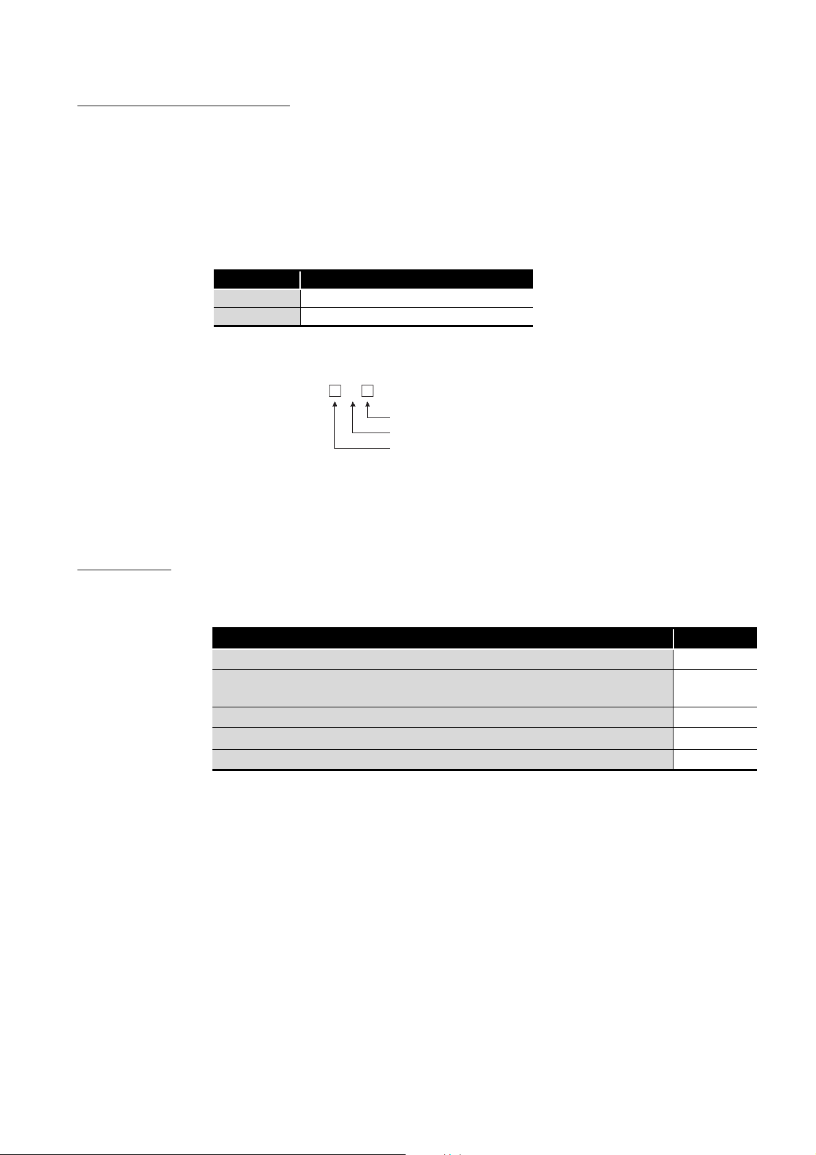
ABBREVIATIONS AND SYMBOLS
The following abbreviations and symbols are used in this manual.
(1) Abbreviations for control station and normal station, and symbol format
This section explains abbreviations for control station and normal station, and symbol
format to be used in this manual.
(a) Abbreviations
Abbreviation Station status
MP Control station
NS Normal station
(b) Symbol format
[Example]
MP
Station number (1 to 120)
Abbreviation
Network No. (1 to 239)
PACKING LIST
1) Network No.3, control station and station number 6: 3M
2) Network No.5, normal station and station number 3: 5N
P6
S3
The packing list of the CC-Link IE Controller Network board is given below.
Item Quantity
Board 1
Connector set (for external power supply cable)
(Q80BD-J71GP21S-SX, Q81BD-J71GP21S-SX only)
"Before Using the Product" 1
Software package (CD-ROM)*
Software license agreement 1
*1: Manuals are stored on the CD-ROM in PDF format.
1
1
1
A - 23
Page 26
1
POINT
OVERVIEW
CHAPTER 1 OVERVIEW
This manual explains the specifications, functions, preparatory procedures and setting,
programming, and troubleshooting of the CC-Link IE Controller Network board.
When applying program examples introduced in this manual to the actual system, it is
necessary to perform a sufficient examination to make sure they don't cause any error in
the system control.
For construction of the CC-Link IE Controller Network, refer to the following manual.
CC-Link IE Controller Network Reference Manual
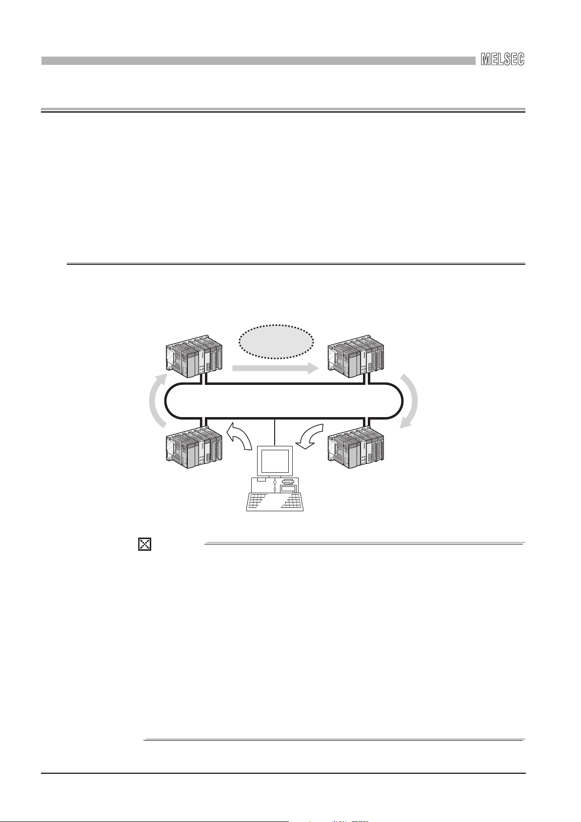
1.1 Overview
The CC-Link IE Controller Network board allows connection of a personal computer to a
CC-Link IE Controller Network, realizing high-speed and large-volume data
communications between the computer and programmable controllers.
High-speed and
large-volume data
communication
CC-Link IE Controller Network
(CC-Link IE Controller Network board)
(1) The CC-Link IE Controller Network is a system developed to improve the
MELSECNET/H network system (PLC-to-PLC network), allowing
communications of a larger data volume at a higher speed.
For details of the comparison between the CC-Link IE Controller Network
board and the MELSECNET/H board, refer to the following Appendix.
Appendix 4 Comparison with the MELSECNET/H Board
(2) CC-Link IE Controller Network boards, MELSECNET/H boards, and
MELSECNET/H modules cannot be mixed in the same network.
(Must be separated into different networks.)
• CC-Link IE Controller Network board:
Used for CC-Link IE Controller Network
• MELSECNET/H board or MELSECNET/H module:
Used for MELSECNET/H or MELSECNET/10
1 - 1
1.1 Overview
Page 27

1
OVERVIEW
1.2 Features
1
The features of the CC-Link IE Controller Network board are shown below.
(1) Personal computer can be incorporated into CC-Link IE Controller
Network.
By installing the CC-Link IE Controller Network board to a personal computer, the
personal computer can be used as a control station or normal station of the CC-Link
IE Controller Network.
(2) Universal PCI, PCI Express® are applicable.
(a) Q80BD-J71GP21-SX, Q80BD-J71GP21S-SX
The following PCI slots are applicable.
•5 V slot
• 3.3 V slot
• 64-bit slot
•PCI-X slot
(b) Q81BD-J71GP21-SX, Q81BD-J71GP21S-SX
®
PCI Express
is applicable.
(3) Operation is easy.
To utilize the CC-Link IE Controller Network board, just install it to a personal
computer and install the software package.
Using the CC IE Control utility, various settings such as channel numbers and station
numbers can be configured easily.
2
SYSTEM
3
4
5
OVERVIEW
CONFIGURATION
SPECIFICATIONS
FUNCTIONS
1.2 Features
PROCEDURES AND
SETTINGS BEFORE
OPERATION
6
PARAMETER
SETTINGS
7
INSTALLING AND
UNINSTALLING
SOFTWARE PACKAGES
8
CC IE Control
UTILITY
1 - 2
Page 28
1
Q80BD-
J71GP21-SX
QJ71GP21
-SX
QCPU
Q80BD-
J71GP21S-SX
Control station (No.1) Normal station (No.3)Normal station (No.2)
External power
supply
External power
supply
Normal station (No.6) Normal station (No.4)Normal station (No.5)
Q81BD-
J71GP21-SX
Q81BD-
J71GP21S-SX
QJ71GP21
-SX
QCPU
Since external power is supplied to stations No.3 and
No.5, networking of all stations continues normally.
If the boards on stations No.3 and No.5 do not have the
external power supply function, they are disconnected
from the network.
Station No.1
Disconnected
Station No.2 Station No.3
Station No.6 Station No.5 Station No.4
Personal computer
Personal computer
OVERVIEW
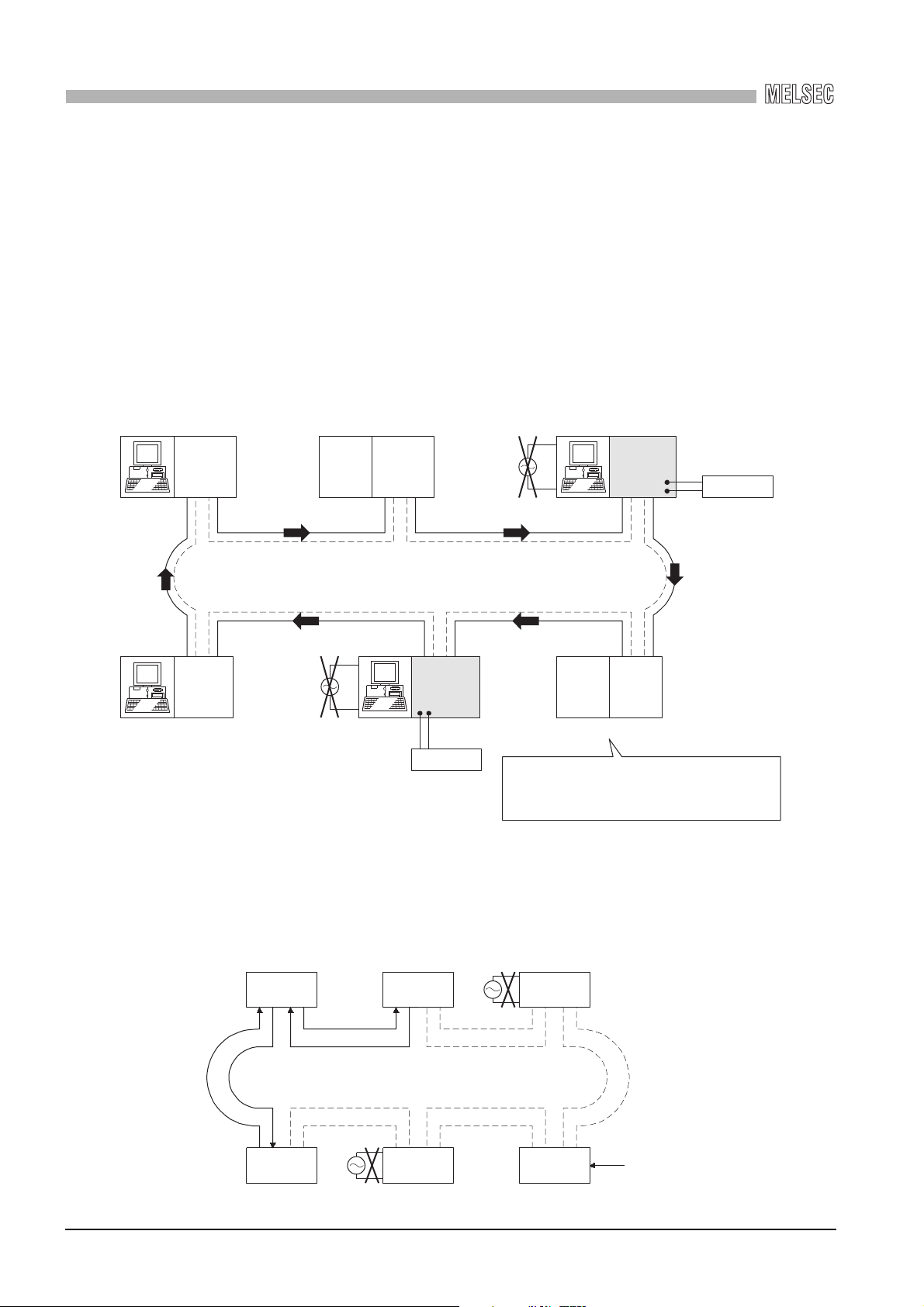
(4) External power supply allows continuous network communication even
during power-off of personal computer. (Function of the CC-Link IE
Controller Network board with external power supply function)
Since power is supplied externally, the CC-Link IE Controller Network board with
external power supply function can continue network communication (baton passing)
even if a personal computer is powered off and data link cannot be performed.
Therefore, a normally operating station connected between other stations with poweroff computers will not be disconnected from the data link.
Another advantage is that the link scan time is stabilized since loopback can be also
prevented.
When CC-Link IE Controller Network boards without the external power supply function
are installed to station number 3 and 5, and if personal computers of these stations are
1 - 3
1.2 Features
powered off, station number 3, 4, and 5 will be disconnected from the network.
Page 29

1
OVERVIEW
(5) Occupying one PCI bus slot
(6) Supporting event function
(7) Keeping application portability with MELSECNET/H board
(8) Drivers are available for each OS.
(9) User programming functions are available.
(10)Supporting Multiple CPU system
Any type of CC-Link IE Controller Network boards including those with external power
supply occupies only one slot.
The event function monitors link devices using the CC-Link IE Controller Network
board, and notifies events to the user program when the set conditions are met.
By only changing settings such as the total number of boards (CC-Link IE Controller
Network boards) installed to a personal computer and channel numbers, any existing
user program created by a MELSECNET/H or MELSECNET/10 board can be utilized.
Since various types of drivers are available, a system suitable to the user environment
can be easily constructed.
For details on the compatible operating system, refer to Section 2.5.
With supported Microsoft® Visual Basic® and Microsoft® Visual C++® functions,
remote control of programmable controllers and device reading/writing can be
performed, and user programs can be created easily.
By specifying a logical station number with the CC IE Control utility, a multiple CPU
system is accessible.
1
2
SYSTEM
3
4
5
OVERVIEW
CONFIGURATION
SPECIFICATIONS
FUNCTIONS
1.2 Features
PROCEDURES AND
SETTINGS BEFORE
OPERATION
6
PARAMETER
SETTINGS
7
INSTALLING AND
UNINSTALLING
SOFTWARE PACKAGES
8
CC IE Control
UTILITY
1 - 4
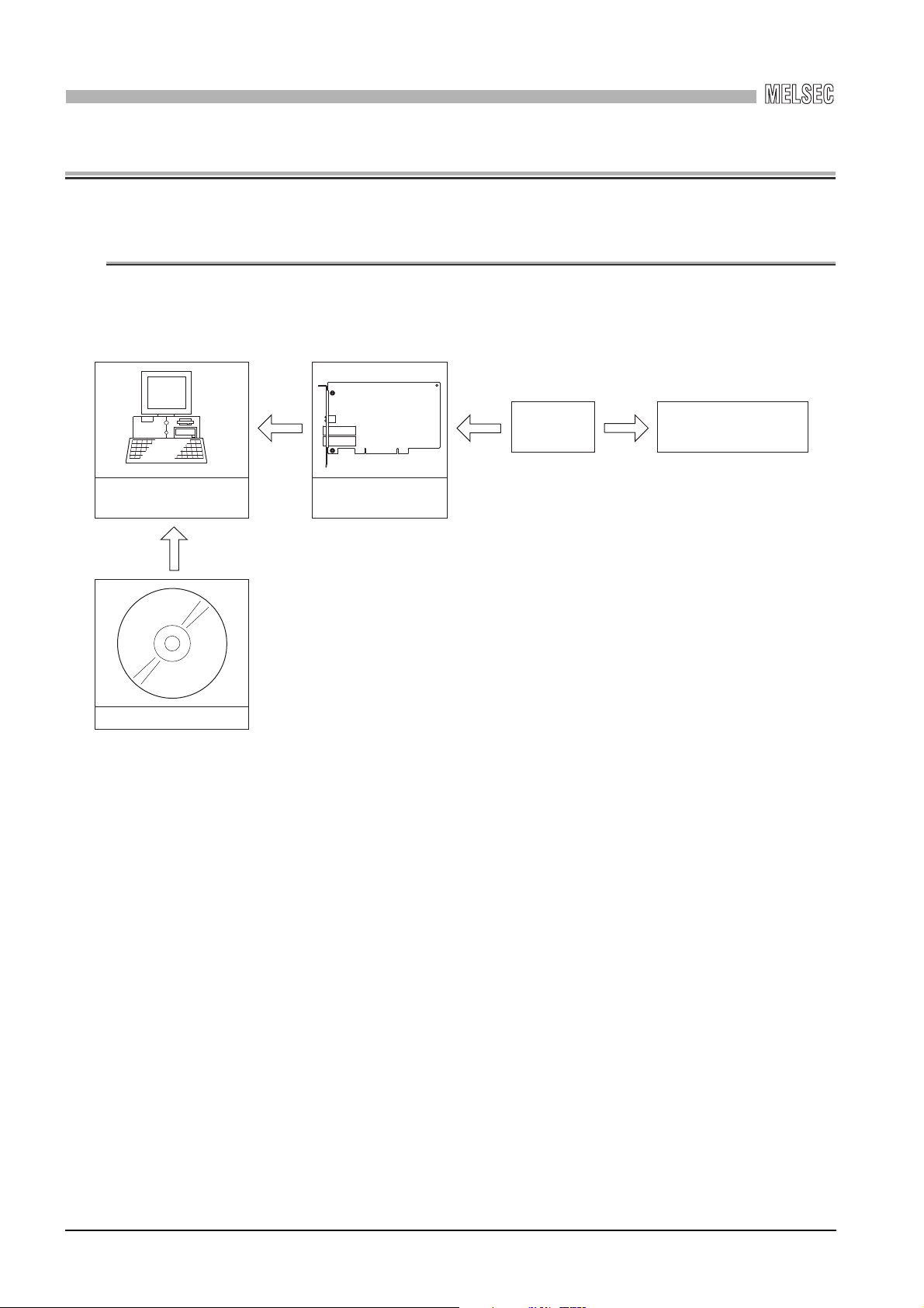
Page 30
2
CC-Link IE Controller
Network board
Personal computer
Installed Connection Connection
Installed
SW1DNC-MNETG-B
Optical fiber
cable
CC-Link IE Controller Network
SYSTEM CONFIGURATION
CHAPTER 2 SYSTEM CONFIGURATION
2.1 System Configuration Using CC-Link IE Controller Network
Board
A system configuration where the CC-Link IE Controller Network board is installed to a
personal computer is shown below.
2 - 1
2.1 System Configuration Using CC-Link IE Controller Network Board
Page 31

2
Q80BD-
J71GP21-SX
Control station
Station No.1
Personal
computer
Power supply
Power supply
QCPUINQJ71
GP21-SX
Normal station
Station No.2
OUT IN OUTIN OUT
QCPU QJ71
GP21-SX
Normal station
Station No.n n 120
<
SYSTEM CONFIGURATION
2.2 Single Network System
A single network system is a system that connects a control station and normal stations
with optical fiber cables.
A total of 120 stations, 1 control station and 119 normal stations, can be connected.
A control station can be any station No.s. (One control station can be connected per
network.)
In the system chart below, the station No.1 is set as the control station.
2.2.1 Configuration
A configuration example of a single network system is shown below.
1
2
SYSTEM
3
4
OVERVIEW
CONFIGURATION
SPECIFICATIONS
FUNCTIONS
5
PROCEDURES AND
SETTINGS BEFORE
OPERATION
6
PARAMETER
SETTINGS
7
INSTALLING AND
UNINSTALLING
SOFTWARE PACKAGES
8
2.2 Single Network System
2.2.1 Configuration
2 - 2
CC IE Control
UTILITY
Page 32

2
SYSTEM CONFIGURATION
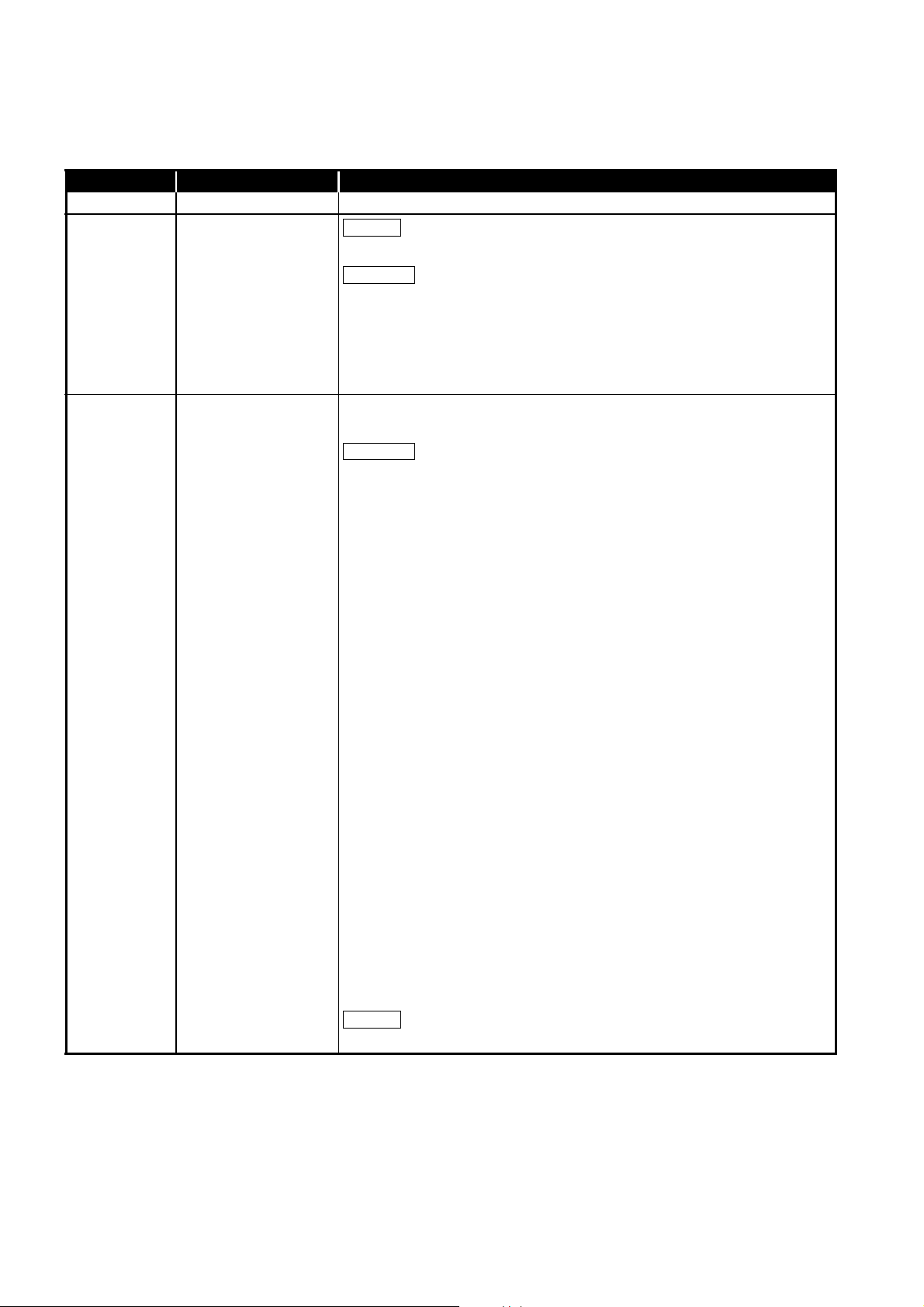
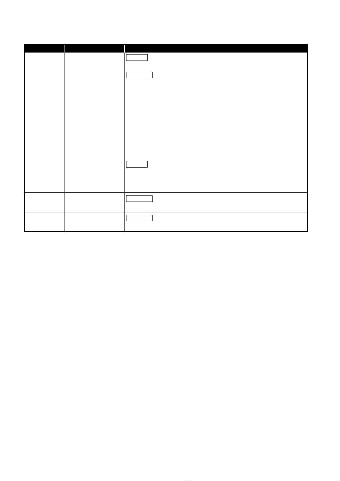
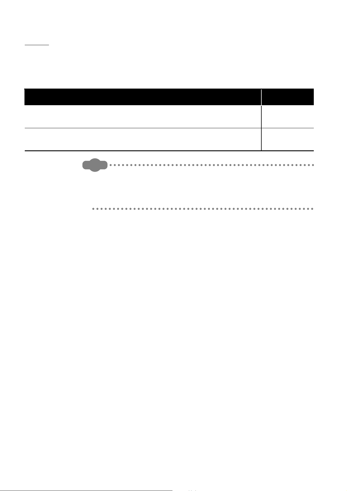
2.2.2 Setting items
In a single network system, the following items are to be set when the CC-Link IE
Controller Network board is used as a control station or a normal station.
CC-Link IE Controller Network board settings are configured in the CC IE Control utility.
Setting item Control station Normal station Reference
Target board specification
Board
Channel No.
Network type
Operational
setting
Network
range
assignment
Driver setting Section 8.4.6
Event setting Section 8.4.7
Target setting Section 8.4.8
Refresh parameter setting Section 8.4.9
Routing parameter Section 8.4.4
Mode
Network No.
Group No.
Stati on No.
LB/LW settings
LX/LY settings
Specify reserved
station
Supplementary
setting
Section 8.4.1
Section 8.4.2
Section 8.4.5
: Setting required : Set as necessary : Setting not required
2.2.3 Available device ranges
The following device ranges can be used on the CC-Link IE Controller Network board.
Device Available range Remarks
LB 0H to 7FFFH (32768 points)
LW 0H to 1FFFFH (131072 points)
LX 0H to 1FFFH (8192 points)
LY 0H to 1FFFH (8192 points)
The ranges for each CC-Link IE Controller Network
board and network module need to be assigned in the
parameter setting for the control station.
The ranges for each CC-Link IE Controller Network
board and network module need to be assigned in the
parameter setting for the control station.
2 - 3
2.2 Single Network System
2.2.2 Setting items
Page 33

2
POINT
Q80BD-
J71GP21-SX
Control station
1M
P
1
Q80BD-
J71GP21-SX
Normal station
2N
S
2
Normal station
1NS2
Control station
2MP1
Power supply
Power supply
Power supply
QCPU QJ71
GP21-SX
QJ71
GP21-SX
Network No.1 Network No.2
Normal station
2N
S
3
QCPU QJ71
GP21-SX
Normal station
1N
S
3
QCPU QJ71
GP21-SX
SYSTEM CONFIGURATION
2.3 Multi-Network System
A multi-network system is composed of multiple networks that are connected by relay
stations.
(1) Any network No. can be set within the range of 1 to 239.
(2) The CC-Link IE Controller Network board cannot be used as a relay station.
Use a network module as a relay station.
2.3.1 Configuration
In the following example, two networks are connected.
1
2
SYSTEM
3
4
OVERVIEW
CONFIGURATION
SPECIFICATIONS
FUNCTIONS
5
PROCEDURES AND
SETTINGS BEFORE
OPERATION
6
PARAMETER
SETTINGS
7
INSTALLING AND
UNINSTALLING
SOFTWARE PACKAGES
8
2.3 Multi-Network System
2.3.1 Configuration
2 - 4
CC IE Control
UTILITY
Page 34

2
SYSTEM CONFIGURATION
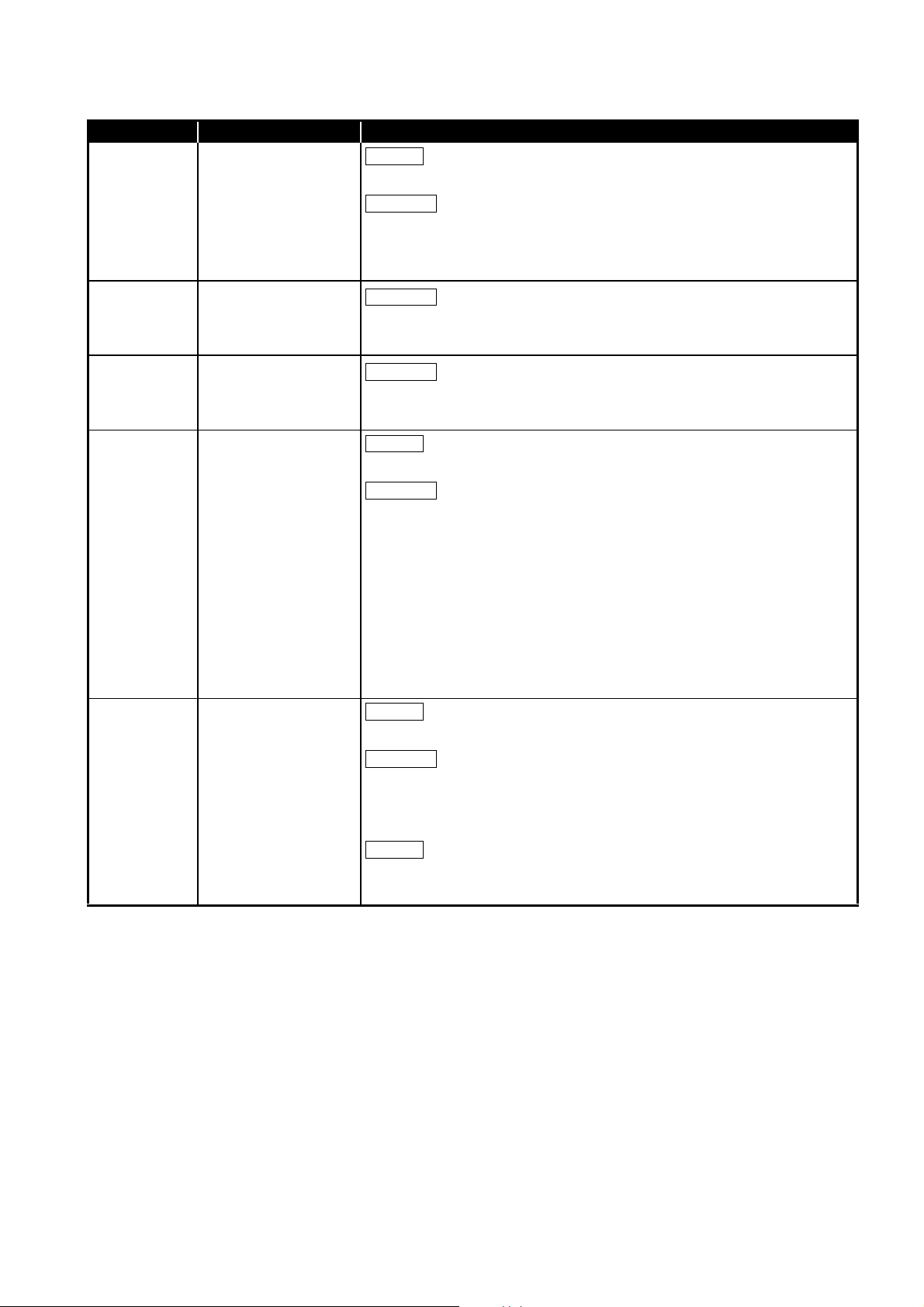
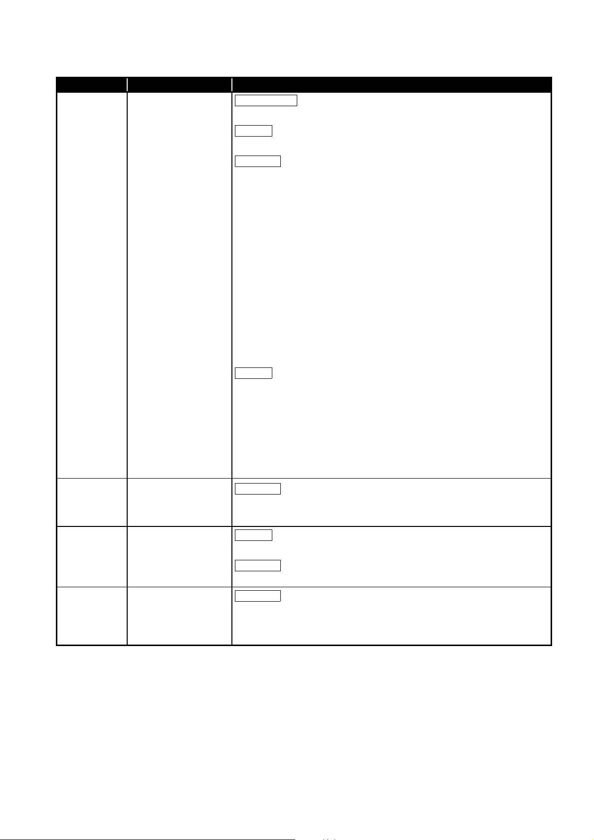
2.3.2 Setting items
In a multi-network system, the following items are to be set when the CC-Link IE Controller
Network board is used as a control station or a normal station.
CC-Link IE Controller Network board settings are configured in the CC IE Control utility.
Setting item Control station Normal station Reference
Target board specification
Board
Channel No.
Network type
Operational
setting
Network
range
assignment
Driver setting Section 8.4.6
Event setting Section 8.4.7
Target setting Section 8.4.8
Refresh parameter setting Section 8.4.9
Routing parameter Section 8.4.4
Mode
Network No.
Group No.
Stati on No.
LB/LW settings
LX/LY settings
Specify reserved
station
Supplementary
setting
Section 8.4.1
Section 8.4.2
Section 8.4.5
: Setting required : Set as necessary : Setting not required
2.3.3 Available device range
The same device ranges as those of a single network system can be used.
Section 2.2.3 Available device ranges.
2 - 5
2.3 Multi-Network System
2.3.2 Setting items
Page 35

2
POINT
SYSTEM CONFIGURATION
2.4 Use in Multiple CPU System or Redundant CPU System
To access a multiple CPU system or redundant CPU system, the "Target setting" screen
setting must be completed.
Section 8.4.8 Target setting screen
When a CC-Link IE Controller Network board with a serial number whose first five
digits are 10091 or lower, or an SW1DNC-MNETG-B with the software Version
1.04E or earlier is used, the redundant CPU system cannot be accessed directly
with the CC-Link IE Controller Network interface board.
Relay the MELSECNET/H network system to access the redundant CPU system.
1
2
SYSTEM
3
4
OVERVIEW
CONFIGURATION
SPECIFICATIONS
FUNCTIONS
5
PROCEDURES AND
SETTINGS BEFORE
OPERATION
6
PARAMETER
SETTINGS
7
INSTALLING AND
UNINSTALLING
SOFTWARE PACKAGES
8
2.4 Use in Multiple CPU System or Redundant CPU System
CC IE Control
UTILITY
2 - 6
Page 36

2
POINT
SYSTEM CONFIGURATION
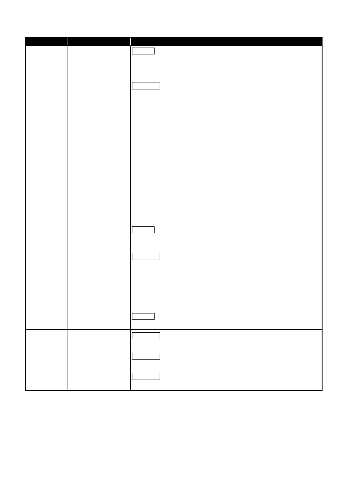
2.5 Operating Environment
The following table shows the operating environment for the CC-Link IE Controller
Network board.
Item Description
Personal computer
CPU
Required memory
PCI bus
specifications
PCI Express®
bus specifications
Available hard disk capacity 1GB or more
Disk drive CD-ROM disk drive
Monitor Resolution: 1024 768 dots or higher
OS (English version)
Programming language
(English version)
*1
*1
Microsoft
System requirements of the operating system must be met.
For Q80BD-J71GP21-SX, Q80BD-J71GP21S-SX
• Compliant with PCI standard Rev.2.2 (3.3VDC/5VDC, 32-bit bus, Reference clock
For Q81BD-J71GP21-SX, Q81BD-J71GP21S-SX
• Compliant with PCI Express
Windows 10 (Home, Pro, Enterprise, Education)
Windows 8.1, Windows 8.1 (Pro, Enterprise)
Windows Server® 2012 R2 (Standard)
Windows 8, Windows 8 (Pro, Enterprise)
Windows Server 2012 (Standard)
Windows 7 (Home Premium, Professional, Ultimate, Enterprise)
Windows Server 2008 R2 (Standard, Enterprise)
When using any of the following operating systems, use SW1DNC-MNETG-B with the
version 1.18U or earlier.
Windows Server 2008 (Standard(x86, x64), Enterprise(x86, x64))
Windows Vista
Windows Server 2003 R2 (Standard(x86, x64), Enterprise(x86, x64)) SP2 or later
Windows XP® (Professional) SP2 or later
When using any of the following operating systems, use SW1DNC-MNETG-B with the
version 1.15R or earlier.
Windows 2000 (Professional)SP4 or later
Visual Basic® and Visual C++® in the following Microsoft Visual Studio®:
Visual Studio® 2015, Visual Studio 2013, Visual Studio 2012, Visual Studio 2010,
Visual Studio 2008, Visual Studio 2005, Visual Studio.NET 2003,
Visual Basic 6.0, Visual C++ 6.0
*1: For a combination of the operation system and the programming language, refer to the Microsoft
*2: Apply Service Pack1 and Security Update for Windows(KB3033929 or KB3125574). Otherwise,
*3: 64-bit version is not supported.
*4: Applicable to Q80BD-J71GP21-SX, Q80BD-J71GP21S-SX only.
®
Windows® supported personal computer
33MHz)
®
standard Rev.1.1 (3.3VDC, Link width 1lane, Reference
clock 100MHz)
®
(Home Basic, Home Premium, Business, Ultimate, Enterprise)
Knowledge Base.
use SW1DNC-MNETG-B with the version 1.18U or earlier.
*2
*2
*3
*3
*4
2 - 7
For the information on how to obtain SW1DNC-MNETG-B version 1.18U or
earlier, refer to the following section.
Appendix 8 Restrictions for Operating System
2.5 Operating Environment
Page 37

2
SYSTEM CONFIGURATION
(1) Instructions for personal computer
(a) PCI standard
When a personal computer which is not compliant with the PCI or PCI Express
standard is used, troubles caused by failures such as a contact failure or
operation error may occur.
For details of the number of boards that can be installed, installation slots, and
occupied slots, refer to the performance specifications in Section 3.2.
(b) Added operating environment
Operating environment Supported version of SW1DNC-MNETG-B
Multiprocessor Version 1.05F or later
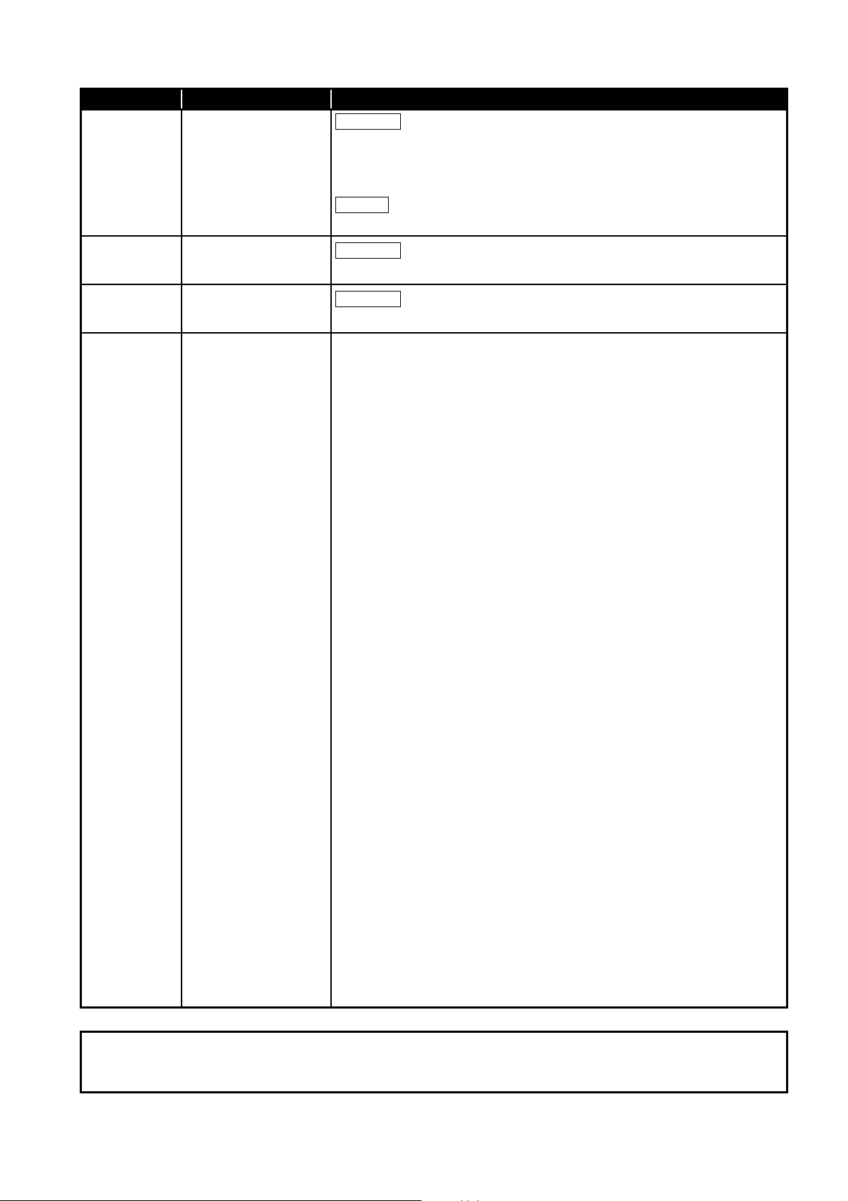
(2) Instructions for operating system
(a) Supported version of SW1DNC-MNETG-B
Operating system
Windows 10 1.22Y or later 1.22Y or later
Windows 8.1, Windows Server 2012 R2 1.17T or later 1.17T or later
Windows 8, Windows Server 2012 1.16S or later 1.16S or later
Windows 7 (64-bit version),
Windows Server 2008 R2
Windows 7 (32-bit version) 1.11M or later
Windows Server 2008 (64-bit version) 1.12N to 1.18U
Windows Server 2008 (32-bit version) 1.11M to 1.18U
Windows Vista 1.02C to 1.18U
Windows Server 2003 R2 (64-bit version) 1.12N to 1.18U
Windows Server 2003 R2 (32-bit version)
Windows XP
Windows 2000
(b) User authority
Log on as a user having administrator authority.
• Installation, uninstallation and usage of utilities are available only by the
administrator's authority.
• Installation and uninstallation are available only by the administrator's
authority.
• The Usage of utilities is available only by the administrator's authority.
(c) Secure Boot function
For the following operating system, disable UEFI (BIOS) Secure Boot function or
use SW1DNC-MNETG-B Version 1.24A or later.
• Windows 10 Version 1607 (Build number '14393' or higher)
*1: It is not included when upgrading from Windows 10 Version 1511 or others by using Windows 10
Anniversary Update.
For the method for checking the version of an operating system and the status of
Secure Boot, refer to technical bulletin FA-A-0235.
Supported version of SW1DNC-MNETG-B
Q80BD-J71GP21-SX,
Q80BD-J71GP21S-SX
1.12N or later
1.18U or earlier
1.15R or earlier (Not supported)
Q81BD-J71GP21-SX,
Q81BD-J71GP21S-SX
1.12N or later
1.12N to 1.18U
*1
1
®
OVERVIEW
2
SYSTEM
CONFIGURATION
3
SPECIFICATIONS
4
FUNCTIONS
5
PROCEDURES AND
SETTINGS BEFORE
OPERATION
6
PARAMETER
SETTINGS
7
INSTALLING AND
UNINSTALLING
SOFTWARE PACKAGES
8
2.5 Operating Environment
CC IE Control
UTILITY
2 - 8
Page 38

2
Remarks
SYSTEM CONFIGURATION
(d) .NET Framework 3.5
When using one of the following operating system, .NET Framework 3.5 is required.
• Windows 10
• Windows 8.1
• Windows Server 2012 R2
• Windows 8
• Windows Server 2012
Enable the .NET Framework 3.5 (including .NET 2.0 or 3.0) in "Turn Windows
features on or off" on the control panel.
(e) Upgrading and updating an operating system
Upgrading an operating system and updating from Windows 8 to Windows 8.1 are
not supported.
Install SW1DNC-MNETG-B by following the procedure:
1. Uninstall SW1DNC-MNETG-B.
2. Upgrade or update the operating system.
3. Install SW1DNC-MNETG-B with the software version supporting the changed
operating system.
(f) The functions cannot be used
If an attempt is made to use any of the following functions, this product may not
operate normally.
• Activating the application with Windows compatible mode.
• Simplified user switch-over
• Remote desktop
• Power save mode (Hibernate, Sleep)
• Fast startup
• The language switching function set by Regional and Language Options
• Windows XP Mode
• Windows Touch or Touch
• Modern UI
• Client Hyper-V
• Server Core Installation
• Tablet mode
• Virtual desktop
In the following cases, the screen of this product may not work properly.
• The size of the text and/or other items on the screen are changed to values
other than default values (such as 96 DPI, 100%, and 9 pt).
• The resolution of the screen is changed in operation.
• The multi-display is set.
2 - 9
• When exiting the operating system, always shut down the computer.
• For the behavior when entering the power save mode, refer to the
following section.
Appendix 10 Behavior When Personal Computer Enters Power Save
Mode or Fast Startup
2.5 Operating Environment
Page 39

2
SYSTEM CONFIGURATION
(3) Instructions for user program
(a) Supported version of SW1DNC-MNETG-B
User program
32-bit version user program
64-bit version user program
*1: Programs can be created and executed on the 64-bit version operating system.
*2: Programs can be created on the 32-bit version operating system, however, the following screen
appears and cannot be executed.
(b) Language environment
User programs created in the Japanese environment work only in the Japanese
environment.
User programs created in the English environment work only in the English
environment.
*1
*2
Supported version of
SW1DNC-MNETG-B
All versions
Version 1.12N or later
1
2
SYSTEM
3
4
OVERVIEW
CONFIGURATION
SPECIFICATIONS
(c) MELSEC data link library
For precautions when using MELSEC data link library, refer to the following
manual.
MELSEC Data Link Library Reference Manual.
FUNCTIONS
5
PROCEDURES AND
SETTINGS BEFORE
OPERATION
6
PARAMETER
SETTINGS
7
2.5 Operating Environment
INSTALLING AND
UNINSTALLING
SOFTWARE PACKAGES
8
CC IE Control
UTILITY
2 - 10
Page 40

3
Remarks
SPECIFICATIONS
CHAPTER 3 SPECIFICATIONS
This chapter explains general and performance specifications of CC-Link IE Controller
Network board.
3.1 General Specifications
The following table shows the general specifications of CC-Link IE Controller Network
board.
Item Specification
Operating ambient temperature 0 to 55 °C
Storage ambient temperature -25 to 75 °C
Operating ambient humidity
Storage ambient humidity
Compliant with
Vibration resistance
Shock resistance
Operating atmosphere No corrosive gases
Operating altitude
Installation location Inside a control panel
Overvoltage category
Pollution degree
*1
*2
*3
JIS B 3502 and
IEC 61131-2
Compliant with JIS B 3502 and IEC 61131-2 (147 m/s
8.4 to 150 Hz
8.4 to 150 Hz
5 to 95 % RH, non-condensing
Under intermittent vibration
Frequency
5 to 8.4 Hz — 3.5 mm
Frequency
5 to 8.4 Hz — 1.75 mm
Constant
acceleration
2
9.8 m/s
Under continuous vibration
Constant
acceleration
2
4.9 m/s
0 to 2000 m
II or less
2 or less
Half amplitude Sweep count
10 times
each in X, Y, Z
—
Half amplitude Sweep count
—
2
, 3 times each in X, Y, Z directions)
directions
—
3 - 1
*1: Do not use or store the board under pressure higher than the atmospheric pressure of altitude 0m.
Doing so may cause malfunction.
*2: This indicates the section of the power supply to which the equipment is assumed to be connected
between the public electrical power distribution network and the machinery within premises.
Category II applies to equipment for which electrical power is supplied from fixed facilities.
The surge voltage withstand level for up to the rated voltage of 300V is 2500V.
*3: This index indicates the degree to which conductive material is generated in terms of the
environment in which the equipment is used.
Pollution degree 2 is when only non-conductive pollution occurs. A temporary conductivity caused
by condensing must be expected occasionally.
The general specifications both CC-Link IE Controller Network board and a
personal computer must be satisfied after installation.
3.1 General Specifications
Page 41

3
SPECIFICATIONS
3.2 Performance Specifications
Performance specifications of the CC-Link IE Controller Network board are shown below.
1
Item Specification
LB 32K points (32768 points, 4K bytes)
Max. link points per
network
Max. link points per
station
Transient transmission capacity Up to 1920 bytes
Communications speed 1G bps
Number of stations per network 120 stations (Control station: 1; Normal station: 119)
Connection cable Optical fiber cable (Multi-mode fiber)
Overall cable distance 66000 m (When 120 stations are connected)
Station-to-station distance (max.)
Max. number of networks 239
Max. number of groups 32
Transmission path Duplex loop
Optical fiber specifications 1000BASE-SX(MMF) optical fiber cable
Connector specifications Duplex LC connector
Laser class (IEC 60825-1) Class 1 laser product
LW 128K points (131072 points, 256K bytes)
LX 8K points (8192 points, 1K byte)
LY 8K points (8192 points, 1K byte)
LB
LW
LX 8K points (8192 points, 1K byte)
LY 8K points (8192 points, 1K byte)
Standard
Transmission loss (max.)
Transmission band (min.)
Standard IEC61754-20: Type LC connector
Connection loss 0.3 (dB) or less
Polished surface PC (Physical Contact) polishing
Normal :16K points (16384 points, 2K bytes)
Extended mode:32K points (32768 points, 4K bytes)
Normal : 16K points ( 16384 points, 32K bytes)
Extended mode:128K points (131072 points, 256K bytes)
550 m (Core/clad = 50/125 ( m))
IEC60793-2-10 Types A1a.1(50/125 m multimode)
3.5 (dB/km) or less ( = 850nm)
500 (MHz
• km) or more ( = 850nm)
OVERVIEW
2
SYSTEM
CONFIGURATION
3
SPECIFICATIONS
4
FUNCTIONS
5
PROCEDURES AND
SETTINGS BEFORE
OPERATION
6
3.2 Performance Specifications
PARAMETER
SETTINGS
7
INSTALLING AND
UNINSTALLING
SOFTWARE PACKAGES
8
CC IE Control
UTILITY
3 - 2
Page 42

3
SPECIFICATIONS
Item
Number of boards that
can be installed
Occupied slots 1 slot
Installation slot
Voltage
Current 0.27A 0.27A
Connector
Applicable
cable size
External
power
supply
Internal current
consumption
Weight 0.12kg 0.14kg 0.13kg 0.14kg
Allowable
momentary
*2
power
failure time
Noise
durability
Q80BD-J71GP21-SX Q80BD-J71GP21S-SX Q81BD-J71GP21-SX Q81BD-J71GP21S-SX
PCI bus slot or PCI-X slot
(Half size)
DC20.4 to DC31.2V
Connector set
(accessory)
0.50 to 1.25mm
[AWG20-16]
No external power
supply function
1.10A (5VDC) 2.07A (3.3VDC)
*1: This indicates the number of CC-Link IE Controller Network boards that can be installed to a
personal computer, not including any other boards such as MELSECNET/H boards.
Note that it cannot exceed the number of physical PCI slots of the personal computer.
*2: Use the power complies with CLASS2.
1ms (level PS1) 1ms (level PS1)
Noise voltage 500Vp-p
Noise width 1 s
(by the noise simulator
with noise frequency
25 to 60Hz)
Specification
*1
Up to 4
PCI Express
(Half size)
2
No external power
supply function
®
x1, x2, x4, x8, x16 slot
DC20.4 to DC31.2V
Connector set
(accessory)
0.50 to 1.25mm
[AWG20-16]
Noise voltage 500Vp-p
Noise width 1 s
(by the noise simulator
with noise frequency
25 to 60Hz)
2
3.3 Optical Fiber Cable Specifications
For optical fiber cables, refer to the following manual.
CC-Link IE Controller Network Reference Manual
3.4 Buffer Memory
For buffer memory, refer to the following manual.
CC-Link IE Controller Network Reference Manual
3 - 3
3.3 Optical Fiber Cable Specifications
Page 43

4
Basic functions
Application
functions
Cyclic transmission function
(Periodical communication)
Cyclic transmission function (Periodical communication)
RAS functions
Transient transmission
function (Non-periodical
communication)
Communication function
Routing function
Group function
Changing number of transient transmissions
Read from/write to other station devices
Communication by LB/LW
Communication by LX/LY
Assurance of cyclic data integrity
(Block data assurance per station
(station-based block data assurance))
Cyclic transmission punctuality assurance
Constant link scan
Control station switching function
Loopback function
Automatic return function
Cable fault detection function
Cable insertion error detection function
Detection of duplicated control
station or station number
Prevention of station failure by
using external power supply
Offline test
Driver WDT function
Event Setting Function
SEND/RECV function
Section 1.2 Features
Section 5.4 Wiring
Section 5.5 Test
Section 12.1.1 Communication function
Section 12.1.2 Routing function
Section 12.1.3 Group function
Section 11.2 Cyclic Transmission
Section 12.2 Event Setting Function
Section 12.1.4 SEND/RECV function
CC-Link IE Controller Network
Reference Manual
CC-Link IE Controller Network
Reference Manual
Section 4.3 Driver WDT function
FUNCTIONS
CHAPTER 4 FUNCTIONS
This chapter explains functions of the CC-Link IE Controller Network board.
4.1 Function List
The following lists the functions of the CC-Link IE Controller Network board.
1
2
SYSTEM
3
4
OVERVIEW
CONFIGURATION
SPECIFICATIONS
4.1 Function List
FUNCTIONS
5
PROCEDURES AND
SETTINGS BEFORE
OPERATION
6
PARAMETER
SETTINGS
7
INSTALLING AND
UNINSTALLING
SOFTWARE PACKAGES
8
CC IE Control
UTILITY
4 - 1
Page 44

4
LB LB
B
LB
END
Sending side (personal computer) Receiving side (programmable controller)
Refresh
data storage
area
Link
refresh
CC-Link IE
Controller Network
driver buffer
User
program
Link data
storage
area *1
Link device
Device
CPU module
CC-Link IE
Controller Network
module
1) B0 turns ON.
2)
3)
4)
Write
Link
refresh
CC-Link IE Controller Network board
Personal computer
Link scan
5)
Sequence scan
B0
6)
Y10
*2
FUNCTIONS
4.2 Specifications on Cyclic Transmission Processing
This section explains the cyclic transmission processing using the CC-Link IE Controller
Network board in the CC-Link IE Controller Network.
4.2.1 Cyclic transmission processing
(1) Cyclic transmission processing
Cyclic transmission is performed using the LB/LW/LX/LY devices of the CC-Link IE
Controller Network board and the CC-Link IE Controller Network module.
The steps shown below are for the case of the link relay (B) on the personal computer
side.
1) B0 on the sending side (personal computer) turns on.
2) By a link refresh, the B0 information is stored in the refresh data storage area
(LB) of the CC-Link IE Controller Network board.
3) The B0 information in the refresh data storage area (LB) is stored in the link
data storage area (LB).
4) By a link scan, the B0 information in the link data storage area (LB) is stored in
a link device (LB) of the CC-Link IE Controller Network module on the
receiving side.
5) By a link refresh, the B0 information is stored in a device (B) of the CPU
module.
6) B0 of the receiving side CPU module turns on.
*1: If the CC-Link IE Controller Network board is a control station, configure settings on the "Network
range assignment" screen of the CC IE Control utility.
*2: Configure settings of refresh ranges on the “Refresh parameter setting” screen of the CC IE
Control utility.
4 - 2
4.2 Specifications on Cyclic Transmission Processing
4.2.1 Cyclic transmission processing
Page 45

4
POINT
Link
refresh cycle
Link scan
Link refresh Link refresh Link refresh
(Set time) (Set time) (Set time) (Set time)
FUNCTIONS
(2) Link scan and link refresh
Link scan is executed 'asynchronously' with the link refresh which is executed by the
CC-Link IE Controller Network board driver.
Link refresh is executed at the interval of time set for "Link refresh cycle" on the
"Driver setting" screen of the CC IE Control utility.
Section 8.4.6 Driver setting screen
Link refresh time can be checked on the "Board detail information" screen.
Section 8.3.3 Board detail information screen
1
2
SYSTEM
3
OVERVIEW
CONFIGURATION
(1) The link refresh may not be executed in the set cycle because of such factors
described below.
• Performance of the personal computer CPU
• Number of set refresh points
• Number of installed CC-Link IE Controller Network boards
• Other running applications
• Other running boards
(2) If the link refresh time exceeds the link refresh cycle set on the "Device
setting” screen, perform any of the following measures.
• Extend the link refresh cycle.
Section 8.4.6 Driver setting screen
• Decrease the refresh points.
(5)(b) in this section How to decrease the refresh points
(3) The link refresh time may be shortened by upgrading the version of CC IE
Control utility or changing assignments of refresh parameters.
If the shortened link refresh time effects the operation of the applications,
perform the following measure.
• Extend the link refresh cycle.
Section 8.4.6 Driver setting screen
SPECIFICATIONS
4
FUNCTIONS
5
PROCEDURES AND
SETTINGS BEFORE
OPERATION
6
PARAMETER
SETTINGS
7
4.2 Specifications on Cyclic Transmission Processing
4.2.1 Cyclic transmission processing
4 - 3
INSTALLING AND
UNINSTALLING
SOFTWARE PACKAGES
8
CC IE Control
UTILITY
Page 46

4
Communication error station
Link data status after disconnection
Disconnected
Disconnected
Area in which link data are held
1NS31NS2
Link data Link data Link data
1NP1
1M
P1
1M
P1
1N
S2
1N
S3
1N
S3
1M
P1
1N
S2
1N
S2
1N
S3
1M
P1
1N
S2
1N
S3
FUNCTIONS
(3) When communication error or communication stop occurs on station
When a communication error station or a communication stop station is detected
during data link, other stations hold the data received from the station immediately
before the error occurrence.
("Communication stop station" is a station to which a peripheral device has stopped
cyclic transmission.)
(a) Normally communicating stations hold the data received from a communication
(b) A communication stop station holds the data received from other stations.
(Example)
When a communication error occurred in 1N
error station or a communication stop station.
S2 due to cable disconnection
(4) SB/SW status when a communication error station/communication stop
4 - 4
4.2 Specifications on Cyclic Transmission Processing
4.2.1 Cyclic transmission processing
station occurs
The status of whether there are any communication error/stop stations on the network
can be checked with the link special relay/register (SB/SW).
Use the link special relay and link special register shown in the following.
Section 11.1.1 Interlock related signals
For interlock program examples, refer to the following manual.
CC-Link IE Controller Network Reference Manual
Page 47

4
POINT
FUNCTIONS
(5) Link refresh
The link refresh is executed between the refresh data storage area and the driver
buffer.
In order to execute the link refresh, set the link refresh cycle and the refresh
parameters in the CC IE Control utility.
(a) Concept of refresh range (points)
Within the range set on the "Refresh parameter setting" screen of the CC IE
Control utility, the range set by the network range assignment is refreshed.
Personal computer
Range to be
actually
refreshed
Device buffer
Link refresh
CC-Link IE controller Network board
Network range
assignment parameter
Station
No.1
Range set by
network range
assignment
1
2
SYSTEM
3
OVERVIEW
CONFIGURATION
(Empty)
Station
No.2
(Empty)
Station
No.3
(Empty)
Range set by
refresh
parameters
(Empty)
Link refresh
(Empty)
Link refresh
(Empty)
The range from the first to the last addresses is set as the initial setting of the
refresh parameter. (Clicking the Default button on the "Refresh parameter setting"
screen of the CC IE Control utility resets the setting to the initial setting.)
SPECIFICATIONS
4
FUNCTIONS
5
PROCEDURES AND
SETTINGS BEFORE
OPERATION
6
PARAMETER
SETTINGS
7
4.2 Specifications on Cyclic Transmission Processing
4.2.1 Cyclic transmission processing
4 - 5
INSTALLING AND
UNINSTALLING
SOFTWARE PACKAGES
8
CC IE Control
UTILITY
Page 48

4
FUNCTIONS
(b) How to decrease the refresh points
Up to 256 refresh ranges can be set for the CC-Link IE Controller Network board.
The refresh points can be decreased by setting only the ranges that need to be
refreshed in the refresh parameter.
Set refresh
parameters for
required part
only
Personal computer
Driver buffer
Link refresh
Link refresh
Link refresh
CC-Link IE controller Network board
Network range assignment parameter
Station
No.1
Station
No.2
Station
No.3
Range set by
network range
assignment
4 - 6
4.2 Specifications on Cyclic Transmission Processing
4.2.1 Cyclic transmission processing
Page 49

4
Remarks
POINT
FUNCTIONS
4.3 Driver WDT function
Driver WDT function monitors the operation of the software (operating system, driver)
inside the hardware by the timer function on CC-Link IE Controller Network board.
When the driver cannot reset the timer of the board within the specified driver WDT
monitoring time, CC-Link IE Controller Network board detects driver WDT error.
Driver WDT function detects driver operation delay due to the access error from the driver
to CC-Link IE Controller Network board or system high load.
(1) Driver WDT settings
For the setting methods, refer to the following section.
Section 8.4.6 Driver setting screen
The driver WDT function is set to invalid as a default.
(2) When the driver WDT error has occurred
The following shows the operation when driver WDT error has occurred.
1
2
SYSTEM
3
4
OVERVIEW
CONFIGURATION
SPECIFICATIONS
(a) CC-Link IE Controller Network board and the driver stop communication and are
disconnected from the network in order to avoid an erroneous output.
(b) RUN LED flicks and RD LED turns ON on the CC-Link IE Controller Network
board.
(c) "-28158 (9202H) Driver WDT error" occurs when accessing CC-Link IE Controller
Network board from the application program in which the CC IE Control utility and
MELSEC data link library function are used.
• When the multiple applications in which MELSEC data link library is used
are executed, driver WDT error is returned to all the programs. However,
only the CC-Link IE Controller Network board in which the driver WDT
error has occurred is recognized as an error station on the network.
When using driver WDT function, set the monitoring timer considering the
margin of the personal computer load.
• For the troubleshooting, refer to the following chapter.
Chapter 14 TROUBLESHOOTING
FUNCTIONS
5
PROCEDURES AND
SETTINGS BEFORE
OPERATION
6
PARAMETER
SETTINGS
7
4.3 Driver WDT function
INSTALLING AND
UNINSTALLING
SOFTWARE PACKAGES
8
CC IE Control
UTILITY
4 - 7
Page 50

5
Set the parameters
Set the parameters and confirm them with the utility.
PROCEDURES AND SETTINGS BEFORE OPERATION
CHAPTER 5 PROCEDURES AND SETTINGS BEFORE
OPERATION
This chapter explains the procedures and settings before operating the CC-Link IE
Controller Network board.
5.1 Procedure before Operation
The following flowchart explains the procedure before operating the CC-Link IE Controller
Network board.
Start
Check
Install the software package
Install the software package on a personal computer.
Section 7.2
Install the board
Install the board to a slot on a personal computer.
For the CC-Link IE Controller Network board with external power supply
function, wire the external power supply cable.
Set the channel number
Set the channel number and confirm it with the utility.
Check the board
Test the hardware of the installed board.
Wire the cables
Wire the network cables for the installed board.
Section 5.3.3
Section 5.4.2
Section 5.3.4
Section 5.5
Section 5.4
Chapter 6
Test the cable connection and data link on the network.
5 - 1
5.1 Procedure before Operation
Check the network
Section 5.5
Page 51

5
Execute a user program
Execute a user program or utility.
Operation
PROCEDURES AND SETTINGS BEFORE OPERATION
1
2
SYSTEM
3
4
OVERVIEW
CONFIGURATION
SPECIFICATIONS
FUNCTIONS
5
PROCEDURES AND
SETTINGS BEFORE
OPERATION
6
PARAMETER
SETTINGS
7
INSTALLING AND
UNINSTALLING
SOFTWARE PACKAGES
8
5.1 Procedure before Operation
CC IE Control
UTILITY
5 - 2
Page 52

5
318G51
BD808C
RD
RUN
ERR.
SD
IN
OUT
2)
1)
24G
+24VDC
NC
RUN
BD808C
317G51
SD RD
ERR.
E.PW
IN
OUT
E.PW
E.PW
2)
3)
4)
1)
PROCEDURES AND SETTINGS BEFORE OPERATION
5.2 Part Names and Settings
This section explains each part name and setting of the CC-Link IE Controller Network
board.
<
Q80BD-J71GP21-SX>
<
Q80BD-J71GP21S-SX>
5 - 3
5.2 Part Names and Settings
Page 53

5
2)
1)
IN
OUT
BD808C
318G51
SD RD
RUN
ERR.
PROCEDURES AND SETTINGS BEFORE OPERATION
<Q81BD-J71GP21-SX>
1
2
SYSTEM
3
4
OVERVIEW
CONFIGURATION
SPECIFICATIONS
E.PW
E.PW
E.PW
IN
OUT
+24VDC
24G
NC
BD808C
317G51
RUN
ERR.
<
Q81BD-J71GP21S-SX>
FUNCTIONS
5
4)
3)
1)
RDSD
PROCEDURES AND
SETTINGS BEFORE
OPERATION
6
2)
PARAMETER
SETTINGS
7
INSTALLING AND
UNINSTALLING
SOFTWARE PACKAGES
8
CC IE Control
UTILITY
5.2 Part Names and Settings
5 - 4
Page 54

5
No. Name Description
1) Indicator LED
PROCEDURES AND SETTINGS BEFORE OPERATION
Indicates the operating status of the CC-Link IE Controller Network board.
(1) in this section
Connector for connecting optical fiber cable
The cable terminal is as shown below.
IN Reverse loop transmission
Optical fiber cable
2)
connector
External power supply
3)
LED
External power supply
4)
cable connector
IN Forward loop reception
OUT Forward loop transmission
OUT Reverse loop reception
For wiring of an optical fiber cable, refer to the following section.
Section 5.4 Wiring
Indicates the status of external power supply.
(2) in this section
Connector for connecting external power supply cable
The cable terminal is as shown below.
(Board top)
24V
24G
E.PW
5 - 5
5.2 Part Names and Settings
Page 55

5
RUN ERR.
SD
RD
RUN ERR.
SD
RD
RUN ERR.
SD
RD
RUN ERR.
SD
RD
<151> <152> <153> <154>
PROCEDURES AND SETTINGS BEFORE OPERATION
1
(1) Indicator LED
Display the operating status of the CC-Link IE Controller Network board.
RUN ERR.
SD
(a) When the RUN LED is ON or OFF
The same LED display as a network module.
Name Status Description
ON Operating normally
RUN
ERR.
SD
RD
OFF
ON
OFF Operating normally
ON Sending data
OFF Data not sent
ON Receiving data
OFF Data not received
One of the following error has occurred.
• Board WDT error (Hardware error)
• Board resetting (The driver is not started.)
Communication error
Confirm the error displayed on "Select station network device status
display" on the "CC-Link IE Controller Network diagnostics result"
screen of CC IE Control utility.
(Section 8.5.1 CC-Link IE Controller Network diagnostics result
screen)
RD
2
SYSTEM
3
4
5
OVERVIEW
CONFIGURATION
SPECIFICATIONS
FUNCTIONS
(b) When the RUN LED is flashing
(c) When checking channel number
An error which is peculiar to boards has occurred.
Refer to the troubleshooting and take appropriate measures.
Name Status Description
RUN ON
ERR. ON PCI bus error has occurred.
RD ON Driver WDT error has occurred.
The status is displayed as shown below according to the current channel number
while opening the "Channel No. Setting" screen. (
One of the following error has occurred.
(Check ERR.LED and RD LED.)
Section 8.3.2)
5.2 Part Names and Settings
5 - 6
PROCEDURES AND
SETTINGS BEFORE
OPERATION
6
PARAMETER
SETTINGS
7
INSTALLING AND
UNINSTALLING
SOFTWARE PACKAGES
8
CC IE Control
UTILITY
Page 56

5
E.PW
PROCEDURES AND SETTINGS BEFORE OPERATION
(2) External power supply
Display the status of external power supply.
Name Status Description
E.PW
OFF External power supply is not supplied.
ON External power supply is being supplied.
5 - 7
5.2 Part Names and Settings
Page 57

5
PROCEDURES AND SETTINGS BEFORE OPERATION
5.3 Installation
This section explains precautions for handling and installation environment of the CC-Link
IE Controller Network board.
5.3.1 Handling precautions
The following explains precautions for handling the CC-Link IE Controller Network board.
1
OVERVIEW
2
WARNING
CAUTION
Do not touch any connectors while power is on. Doing so may cause
electric shock or malfunction.
Do not directly touch any conductive parts and electronic components of the
board. Doing so may cause malfunction or failure of the board.
Do not disassemble or modify the board. Doing so may cause failure,
malfunction, injury, or a fire.
Before handling the board, touch a conducting object such as a grounded
metal to discharge the static electricity from the human body. Failure to do
so may cause the board to fail or malfunction.
Handle the board in a place where static electricity will not be generated.
Failure to do so may cause a failure or malfunction.
The board is included in an antistatic envelope.
When storing or transporting it, be sure to put it in the antistatic envelope.
Failure to do so may cause a failure or malfunction.
Do not drop or apply a strong impact to the board.
Doing so may cause a failure or malfunction.
Prevent foreign matter such as dust or wire chips from entering the personal
computer. Such foreign matter may cause a fire, failure, or malfunction.
When disposing of this product, treat it as industrial waste.
SYSTEM
CONFIGURATION
3
SPECIFICATIONS
4
FUNCTIONS
5
PROCEDURES AND
SETTINGS BEFORE
OPERATION
6
5.3 Installation
5.3.1 Handling precautions
5 - 8
PARAMETER
SETTINGS
7
INSTALLING AND
UNINSTALLING
SOFTWARE PACKAGES
8
CC IE Control
UTILITY
Page 58

5
Start
Wire the external power supply
For the CC-Link IE Controller Network board with external power supply
function, wire the external power supply cable.
PROCEDURES AND SETTINGS BEFORE OPERATION
5.3.2 Installation environment
For installation of the personal computer in which the CC-Link IE Controller Network board
is installed, refer to the manual for the personal computer.
CAUTION
5.3.3 Board installation
The following flowchart shows the board installation procedure.
Power OFF the personal computer.
Install the board to a slot on a personal computer.
Use the board in an environment that meets the general specifications in
this manual.
Failure to do so may result in electric shock, fire, malfunction, or damage to
or deterioration of the product.
Always ground the personal computer to the protective ground conductor.
Failure to do so may cause a malfunction.
Power OFF
Install the board
Fix the board
Fix the board to a slot on the personal computer using the board-fixing
screws.
Power ON
Power ON the personal computer.
5 - 9
5.3 Installation
5.3.2 Installation environment
Section 5.4.2
End
Page 59

5
PROCEDURES AND SETTINGS BEFORE OPERATION
1
WARNING
CAUTION
Shut off the external power supply for the system in all phases before
installing the board to or removing it from the personal computer.
Failure to do so may result in electric shock or cause the board to fail or
malfunction.
Fix the board by tighten the board-fixing screws.
Tighten the board-fixing screws within the specified torque range.
Undertightening may cause drop of the component, short circuit, or
malfunction.
Overtightening may damage the screw and/or board, resulting in drop, short
circuit, or malfunction.
For the tightening torque of the board-fixing screws, refer to the manual
supplied with the personal computer.
Before handling the board, touch a conducting object such as a grounded
metal to discharge the static electricity from the human body. Failure to do
so may cause the board to fail or malfunction.
Install the board to a personal computer which is compliant with PCI standard
®
or PCI Express
to do so may cause a failure or malfunction.
Securely insert the board into the PCI slot following the board installation
instruction of the personal computer.
Incorrect insertion of the board may lead to a malfunction, failure or drop of
the board.
When installing the board, take care not to get injured by an implemented
component or a surrounding member.
standard (
Section 2.5 Operating Environment). Failure
2
SYSTEM
3
4
OVERVIEW
CONFIGURATION
SPECIFICATIONS
5.3.4 Setting Channel Numbers
Channel number is set per board, and used to identify the board. The channel number can
be set within the range of 151 to 154.
Channel numbers being set are used to specify the target boards in setting parameters
and performing the MELSEC data link library function.
(1) Setting method
Channel No. is assigned to the CC-Link IE Controller network board installed in a
personal computer in order of PCI slot number automatically. The desired channel No.
can be assigned on the "Parameter setting" screen (
Control utility. (
Section 6.1)
Section 8.4.1) of CC IE
FUNCTIONS
5
PROCEDURES AND
SETTINGS BEFORE
OPERATION
6
PARAMETER
SETTINGS
7
INSTALLING AND
UNINSTALLING
SOFTWARE PACKAGES
8
5.3 Installation
5.3.4 Setting Channel Numbers
5 - 10
CC IE Control
UTILITY
Page 60

5
Remarks
PROCEDURES AND SETTINGS BEFORE OPERATION
5.4 Wiring
This section explains precautions for connecting cables to the CC-Link IE Controller
Network board.
(1) Precautions for general wiring
WARNING
CAUTION
CAUTION
Shut off the external power supply for the system in all phases before
installing the board or starting wiring.
Failure to do so may result in electric shock, damage to the product, or
malfunction.
After installation of the board and wiring, attach the cover on the module
before turning it on for operation.
Failure to do so may result in electric shock.
When disconnecting the cable from the board, do not pull the cable by the
cable part.
Pulling the cable connected to the board may result in malfunction or
damage to the board or cable.
Prevent foreign matter such as dust or wire chips from entering the personal
computer.
Such foreign matter may cause a fire, failure, or malfunction.
Always ground the personal computer to the protective ground conductor.
Failure to do so may cause a malfunction.
(2) Precautions for communication cable wiring
Place the communication cable and the external power supply cable
connected to the board in a duct or clamp them.
If not, dangling cables may swing or inadvertently be pulled, resulting in
damage to the board or cables or malfunctions due to poor contact.
Special skills and tools are required to connect the communication cable to
the connector plug, which is an exclusive product.
When purchasing it, please consult your local Mitsubishi representative.
Incomplete connection can result in a short, fire or malfunction.
Securely plug the communication cable to the connector of the board. Then,
check for any incomplete connection.
Poor contact may cause an erroneous input or output.
5 - 11
For optical fiber cables, refer to the following manual.
CC-Link IE Controller Network Reference Manual
5.4 Wiring
Page 61

5
PROCEDURES AND SETTINGS BEFORE OPERATION
1
(3) Precautions for external power supply cable wiring
CAUTION
Place the communication cable and the external power supply cable
connected to the board in a duct or clamp them.
If not, dangling cables may swing or inadvertently be pulled, resulting in
damage to the board or cables or malfunctions due to poor contact.
Check the rated voltage and pin-out before wiring to the external power
supply cable, and connect the cables correctly. Connecting a power supply
with a different voltage rating or incorrect wiring may cause a fire or failure.
Do not install the external power supply or communication cables together
with the main circuit lines or power cables.
Keep a distance of 100mm (3.94 in.) or more between them. Failure to do
so may result in malfunction due to noise.
Use a specified tool for crimping of the cable and contacting pin. Imperfect
crimping may cause a malfunction.
Verify the pin-out and fully insert the crimped contacting pin into the
connector. Imperfect insertion may cause a failure or malfunction.
Insert the wired external power supply cable into the external power supply
cable connector until a click is heard. Imperfect insertion may cause a
failure or malfunction.
2
SYSTEM
3
4
5
OVERVIEW
CONFIGURATION
SPECIFICATIONS
FUNCTIONS
5.4 Wiring
PROCEDURES AND
SETTINGS BEFORE
OPERATION
6
PARAMETER
SETTINGS
7
INSTALLING AND
UNINSTALLING
SOFTWARE PACKAGES
8
CC IE Control
UTILITY
5 - 12
Page 62

5
PROCEDURES AND SETTINGS BEFORE OPERATION
5.4.1 Controller network system
The following explains precautions for connecting the optical fiber cables with the CC-Link
IE Controller Network board.
(1) Precautions for connection
(a) Use the dedicated optical fiber cable shown below for the controller network
system.
Typ e Model name (maker)
Multi-mode fiber (GI) QG series (Mitsubishi electric system & service Co., Ltd.)
(b) When connecting an optical fiber cable to the CC-Link IE Controller Network
board, the cable bend radius is restricted.
For details, check the specifications of the cable used.
(c) When laying the optical fiber cables, do not touch the fiber cores of the cable-side
and board-side connectors, and protect them from dirt and dust.
If oil from the hand, dirt or dust is attached to the core, it can increase
transmission loss, causing a problem in data link.
(d) When connecting or disconnecting an optical fiber cable, hold the connector part
of the cable.
(e) Make a full connection between the cable-side and board-side connectors until a
"click" can be heard.
(f) When installing the CC-Link IE Controller Network board to the personal
computer, secure a space of around 10 mm (0.39 in.) to the right and left of the
optical connector. Depending on the adjacent boards and installing slot position,
connecting/disconnecting the optical cable may be difficult. In this case, use the
following dedicated tool.
Model name Maker
SCT-SLM Mitsubishi electric system & service Co., Ltd.
CC-Link IE Controller Network board
Board-side connector
5 - 13
Cable-side connector
Connector hook
5.4 Wiring
5.4.1 Controller network system
Page 63

5
E
Connector
hook
Board-side
connector
CC-Link IE Controller Network board
Cable-side
connector
Connection
Power OFF the personal computer.
Connect the cable-side connector to the
board-side one, paying attention to the
orientation. Push it until a "click" can be
heard.
Lightly pull it to check that it is securely
connected.
End
End
Disconnection
Power OFF the personal computer.
Press the connector hook to disconnect the
cable.
Connector
hook
Board-side
connector
CC-Link IE Controller Network board
Cable-side
connector
PROCEDURES AND SETTINGS BEFORE OPERATION
(2) Cable connection
(a) Connection method
Connect an optical fiber cable between OUT and IN as shown below.
Note that there is no need to connect the cables in the order of station numbers.
1
OVERVIEW
2
Control station
Station number 1
Personal
computer
CC-Link IE
Controller
Network
board
IN OUT IN OUT IN OUT
Normal station Normal station
Station number 2 Station number n
QCPU
Power supply module
CC-Link IE
Controller
Network
module
QCPU
Power supply module
(b) Connecting the optical fiber cable
The following shows the method for connecting the optical fiber cable.
<
n 120
CC-Link I
Controller
Network
module
SYSTEM
3
4
5
CONFIGURATION
SPECIFICATIONS
FUNCTIONS
(c) Disconnecting the optical fiber cable
The following shows the method for disconnecting the optical fiber cable.
5.4 Wiring
5.4.1 Controller network system
5 - 14
PROCEDURES AND
SETTINGS BEFORE
OPERATION
6
PARAMETER
SETTINGS
7
INSTALLING AND
UNINSTALLING
SOFTWARE PACKAGES
8
CC IE Control
UTILITY
Page 64

5
Start
Check the required parts.
Wire external power supply cable.
Connect the external power supply cable.
End
(2) Parts and tools required for external
power supply cable in this section
(3) Making external power supply cable
in this section
(4) Connecting external power supply
cable to the board in this section
PROCEDURES AND SETTINGS BEFORE OPERATION
5.4.2 Wiring external power supply cable
This section explains the method for connecting external power supply cable to the CCLink IE Controller Network board with external power supply function.
(1) Connection procedure
The following flowchart shows a procedure for connecting external power supply
cable.
(2) Parts and tools required for external power supply cable
The following parts and tools are required for making external power supply cable.
(a) Connector set (accessories)
Check that the following parts are included with the attached connector set.
Typ e Model name Applicable wire size Quantity
Connector 1-178288-3 — 1
Contact 175218-2 AWG#20-16 3 (Spare 1)
(b) Cable
Use an external power supply cable with heat-resistant vinyl sheath of 0.5 to 1.25
2
[AWG#20-16].
mm
(c) Tool
Use the following specified crimp tools.
Model Applicable wire size Inquiry
91558-1
AWG#20-16 Tyco Electronics
1762956-1
5 - 15
5.4 Wiring
5.4.2 Wiring external power supply cable
Page 65

5
POINT
Contacting pin
Cable
24V
24G
Contacting pin
Connector
PROCEDURES AND SETTINGS BEFORE OPERATION
1
(3) Making external power supply cable
The following explains the method for making external power supply cable.
(a) Crimping a contacting pin
Using a crimp tool, crimp the cable and contacting pin.
Set the contacting pin and cable in the grooves of the crimp tool, squeeze the
handle, and make them stick together tightly.
For details of the crimp, refer to the instruction of the tool.
A strip length of the cable should be 5 to 7 mm (1/5 to 2/7 in.)
(b) Check for a crimp
Check if the cable (including a part of the sheath)
is evenly crimped to the contacting pin.
If the cable part is crimped but not the sheath part
or the cable is stuck out, the cable cut or a
malfunction may result.
(c) Connecting to the connector
According to the following pin-out, fully
insert the crimped cable to the connector
until a click is heard.
2
SYSTEM
3
4
5
OVERVIEW
CONFIGURATION
SPECIFICATIONS
FUNCTIONS
Pin No. Description
124V
2 24G
3 Open
(4) Connecting external power supply cable to the board
Properly insert the wired external power supply cable to the external power supply
cable connector of the CC-Link IE Controller Network board until a click is heard.
Keep the cable away from the main circuit cable, power cables and/or the load cables
for any other than programmable controllers. Ensure a distance of 100 mm (3.94 in.)
between them.
Be sure to twist the external power supply cable.
PROCEDURES AND
SETTINGS BEFORE
OPERATION
6
PARAMETER
SETTINGS
7
INSTALLING AND
UNINSTALLING
SOFTWARE PACKAGES
8
5.4 Wiring
5.4.2 Wiring external power supply cable
5 - 16
CC IE Control
UTILITY
Page 66

5
POINT
PROCEDURES AND SETTINGS BEFORE OPERATION
5.5 Test
Item Test type Description Reference
Board confirmation
Network confirmation
Before executing data link, check the CC-Link IE Controller Network board and cables.
Select a test item using the mode setting on the "Parameter setting" screen in the CC IE
Control utility.
The CC-Link IE Controller Network board test has the following six types.
Bus I/F test
H/W test
Self-loopback test
Circuit test
Station-to-station test
Communication test
Tests the hardware of the bus I/F function of the CC-Link IE
Controller Network board.
Tests the hardware in the CC-Link IE Controller Network
board.
Tests the hardware of the CC-Link IE Controller Network
board alone, including the send/receive circuit of the
transmission system and cables.
Checks the cable connection status, line status, and
parameter setting status of each station from the control
station.
Checks the cable status connected between two stations
(from OUT at the executing station to IN at the target
station).
Checks whether the transient transmission can be routed
correctly between the own station and specified
communication target.
Section 5.5.1
Section 5.5.2
Section 5.5.3
Section 5.5.4
Section 5.5.5
Section 5.5.6
The test modes are equivalent to offline. The data link cannot be executed if one
station is set to the test mode during data link. Set the mode to "Online" when
performing data link.
5 - 17
5.5 Test
Page 67

5
Setting
Yes
PROCEDURES AND SETTINGS BEFORE OPERATION
5.5.1 Bus I/F test
This test checks the hardware of the Bus I/F function of the CC-Link IE Controller Network
board.
(1) In the "Parameter setting" screen of the CC IE Control utility, set Mode to
1
OVERVIEW
2
"Bus I/F test" and click the button.
END
(2) The following confirmation dialog box appears.
Clicking the button executes the bus I/F test.
SYSTEM
3
4
5
CONFIGURATION
SPECIFICATIONS
FUNCTIONS
(3) The result is displayed on Test result field of the "Board detail
information" screen.
<Normal completion> <Abnormal completion>
If the test completes abnormally, consult your local Mitsubishi representative.
5.5 Test
5.5.1 Bus I/F test
5 - 18
PROCEDURES AND
SETTINGS BEFORE
OPERATION
6
PARAMETER
SETTINGS
7
INSTALLING AND
UNINSTALLING
SOFTWARE PACKAGES
8
CC IE Control
UTILITY
Page 68

5
END
Yes
PROCEDURES AND SETTINGS BEFORE OPERATION
5.5.2 H/W test
This tests the hardware in the CC-Link IE Controller Network board.
(1) In the "Parameter setting" screen of the CC IE Control utility, set Mode to
"H/W test" and click the button.
Setting
(2) The following confirmation dialog box appears.
Clicking the button executes the H/W test.
(3) The result is displayed on Test result field of the "Board detail
information" screen.
If the test completes abnormally, consult your local Mitsubishi representative.
<Normal completion> <Abnormal completion>
5 - 19
5.5 Test
5.5.2 H/W test
Page 69

5
Setting
Yes
PROCEDURES AND SETTINGS BEFORE OPERATION
5.5.3 Self-loopback test
This tests the hardware of the CC-Link IE Controller Network board alone, including the
send/receive circuit of the transmission system and cables.
(1) Connect optical fiber cables to the IN and OUT of the CC-Link IE
Controller Network board.
1
2
SYSTEM
3
4
OVERVIEW
CONFIGURATION
SPECIFICATIONS
(2) In the "Parameter setting" screen of the CC IE Control utility, set Mode to
"Self-loopback test" and click the button.
END
(3) The following confirmation dialog box appears.
FUNCTIONS
5
PROCEDURES AND
SETTINGS BEFORE
OPERATION
6
PARAMETER
SETTINGS
7
INSTALLING AND
UNINSTALLING
SOFTWARE PACKAGES
8
Clicking the button executes the self-loopback test.
5.5.3 Self-loopback test
5.5 Test
5 - 20
CC IE Control
UTILITY
Page 70

5
PROCEDURES AND SETTINGS BEFORE OPERATION
(4) The result is displayed on Test result field of the "Board detail
information" screen.
<Normal completion> <Abnormal completion>
If the test completes abnormally, replace the optical fiber cable and execute the test
again.
If it fails again, the CC-Link IE Controller Network board hardware may be faulty.
Please consult your local Mitsubishi representative, explaining a detailed description
of the problem.
5 - 21
5.5 Test
5.5.3 Self-loopback test
Page 71

5
POINT
Remarks
PROCEDURES AND SETTINGS BEFORE OPERATION
5.5.4 Circuit test
This test checks the cable connection status and line status in the network system and
parameter setting status of each station from the control station.
The following explains a procedure for circuit test, assuming the executing station is the
CC-Link IE Controller Network board and the target station as the CC-Link IE Controller
Network module.
The circuit test can be executed only when the CC-Link IE Controller Network
board is the control station.
When it is the normal station, execute the test from the control station in the
network system to which the normal station is connected.
1
2
SYSTEM
3
OVERVIEW
CONFIGURATION
This section explains CC-Link IE Controller Network board.
For the setting of network module, refer to the following manual.
CC-Link IE Controller Network Reference Manual
(1) Check for the power discontinuity
Power OFF the personal computer.
Power OFF the module.
(2) Cable connection
Connect optical fiber cables to OUT and IN of each station.
(3) Power-ON
Power ON the personal computer.
Power ON the module.
SPECIFICATIONS
4
FUNCTIONS
5
PROCEDURES AND
SETTINGS BEFORE
OPERATION
6
PARAMETER
SETTINGS
7
5.5 Test
5.5.4 Circuit test
5 - 22
INSTALLING AND
UNINSTALLING
SOFTWARE PACKAGES
8
CC IE Control
UTILITY
Page 72

5
END
Yes
PROCEDURES AND SETTINGS BEFORE OPERATION
(4) Test mode settings
(a) Setting the executing station
Set as follows on the "Parameter setting" screen of the CC IE Control utility.
Network type: CC IE Control (Control station)
Mode: Circuit test
Station No.: Station number for the executing station
Setting
(b) Setting the target station
In the network parameter of GX Works2, set the mode to Online.
*1: If the CC-Link IE Controller Network board is the target station, set as follows on the "Parameter
setting" screen of the CC IE Control utility.
Network type: CC IE Control (Normal station)
Mode: Online
Station No.: Station number for the target station
*1
(5) Starting the test
Clicking the button on the "Parameter setting" screen of the CC IE Control
utility displays the following confirmation dialog box.
Clicking the button executes the circuit test.
5 - 23
5.5 Test
5.5.4 Circuit test
Page 73

5
PROCEDURES AND SETTINGS BEFORE OPERATION
1
(6) Checking the test result
The result is displayed on Test result field of the "Board detail information" screen.
<Normal completion> <Abnormal completion>
If the test completes abnormally, check the error cause on the "CC-Link IE Controller
Network diagnostics result" screen of the CC IE Control utility, process the error with
following the troubleshooting.
Section 8.5.1 CC-Link IE Controller Network diagnostics result screen
Then, reexecute the circuit test.
2
SYSTEM
3
4
5
OVERVIEW
CONFIGURATION
SPECIFICATIONS
FUNCTIONS
5.5 Test
5.5.4 Circuit test
5 - 24
PROCEDURES AND
SETTINGS BEFORE
OPERATION
6
PARAMETER
SETTINGS
7
INSTALLING AND
UNINSTALLING
SOFTWARE PACKAGES
8
CC IE Control
UTILITY
Page 74

5
Remarks
IN
OUT
IN
OUT
Optical fiber cable
Target stationExecuting station
Station
No. n + 1
Side
Station
No. n
Side
PROCEDURES AND SETTINGS BEFORE OPERATION
5.5.5 Station-to-station test
This test checks the cable connected between two stations (from OUT at the executing
station to IN at the target station).
The following explains a procedure for station-to station test, assuming the executing
station is the CC-Link IE Controller Network board and the target station as the CC-Link IE
Controller Network module.
This section explains CC-Link IE Controller Network board.
For the setting of network module, refer to the following manual.
CC-Link IE Controller Network Reference Manual
(1) Check for the power discontinuity
Power OFF the personal computer.
Power OFF the module.
(2) Cable connection
Connect an optical fiber cable to OUT at the executing station and IN at the target
station.
(3) Power-ON
Power ON the personal computer.
Power ON the module.
(4) Test mode settings
(a) Setting the executing station
Set as follows on the "Parameter setting" screen of the CC IE Control utility.
Network type: CC IE Control (Control station)
Mode: Test between station
Station No.: Station number for the executing station
5 - 25
5.5 Test
5.5.5 Station-to-station test
Setting
Page 75

5
END
Yes
PROCEDURES AND SETTINGS BEFORE OPERATION
(b) Setting the target station
In the network parameter of GX Works2, set the mode to Online.
1
*1
*1: If the CC-Link IE Controller Network board is the target station, set as follows on the "Parameter
setting" screen of the CC IE Control utility.
Network type: CC IE Control (Normal station)
Mode: Online
Station No.: Station number for the target station
(5) Starting the test
Clicking the button on the "Parameter setting" screen of the CC IE Control
utility displays the following confirmation dialog box.
Clicking the button executes the station-to-station test.
(6) Checking the test result
The result is displayed on Test result field of the "Board detail information" screen.
<Normal executing > <Abnormal completion>
2
SYSTEM
3
4
5
OVERVIEW
CONFIGURATION
SPECIFICATIONS
FUNCTIONS
If the above display remains
for about 10 seconds, the result is
normal.
If the test completes abnormally, the cable used for the station-to-station test is faulty.
Replace the cable.
5.5 Test
5.5.5 Station-to-station test
5 - 26
PROCEDURES AND
SETTINGS BEFORE
OPERATION
6
PARAMETER
SETTINGS
7
INSTALLING AND
UNINSTALLING
SOFTWARE PACKAGES
8
CC IE Control
UTILITY
Page 76

5
Communication test
PROCEDURES AND SETTINGS BEFORE OPERATION
5.5.6 Communication test
Communication test is a test to check whether the transient transmission can be routed
correctly between the own station and specified communication target.
Note that, however, this test cannot be used during the circuit test.
The following explains the procedure for a communication test.
(1) Click the button on the "CC-Link IE Controller Network
diagnostics result" screen of the CC IE Control utility.
Click
(2) The "Communication test" screen is displayed.
5 - 27
5.5 Test
5.5.6 Communication test
Page 77

5
Execute test
ClickSetting items
PROCEDURES AND SETTINGS BEFORE OPERATION
(3) Set the items shown below, and click the button to execute
the communication test.
Section 8.5.2 Communication test screen
(4) When the communication test is completed, a communication test result
is displayed. If an error occurs, perform the measure by following the
error message.
1
2
SYSTEM
3
4
OVERVIEW
CONFIGURATION
SPECIFICATIONS
FUNCTIONS
5
PROCEDURES AND
SETTINGS BEFORE
OPERATION
6
PARAMETER
SETTINGS
7
INSTALLING AND
UNINSTALLING
SOFTWARE PACKAGES
8
CC IE Control
UTILITY
5.5 Test
5.5.6 Communication test
5 - 28
Page 78

6
Write parameters to the personal computer by clicking the
End button of the "Parameter setting" screen.
Set the followings as necessary.
(1) Routing parameter settings
(2) Event settings
(3) Target settings
(when accessing the multiple CPU system or redundant
CPU system)
(4) Refresh parameter settings
Set the followings as necessary.
(1) I/O master station settings
(2) Reserved station settings
(3) Driver settings
(4) Supplementary settings
Yes
No
Is it a control station?
Board information settings
(1) Channel No. 151 to 154
Operational settings
(1) Network type
(2) Mode
(3) Network No.
(4) Group No.
(5) Station No.
Network range assignment settings
(1) LB/LW settings
(2) LX/LY settings
(3) Total number of link stations
Control station, Normal station
Such as Online and Offline
1 to 239
0 to 32
1 to 120
Section 6.1 Parameter Settings
(Board Information Settings)
Section 6.3.1 LB/LW settings
Section 6.3.2 LX/LY settings
Section 6.3.3 Total number of link stations
Section 6.3.4 Specifying I/O master station
Section 6.3.5 Specifying reserved stations
Section 6.7 Driver Settings
Section 6.6 Supplementary Settings
Section 6.5 Routing Parameter Settings
Section 6.8 Event Settings
Section 6.9 Target Settings
Section 6.10 Refresh Parameter Setting
PARAMETER SETTINGS
CHAPTER 6 PARAMETER SETTINGS
It is necessary to set the parameters using the CC IE Control utility in order to operate the
CC-Link IE Controller Network.
The following is a flow chart for setting parameters.
6 - 1
Page 79

6
PARAMETER SETTINGS
6.1 Parameter Settings (Board Information Settings)
This function is used to set a channel number, network type, and other settings of the CCLink IE Controller Network board to be used.
The parameter settings are set on the "Parameter setting" screen in the CC IE Control
utility.
Section 8.4.1 Parameter setting screen
1
2
SYSTEM
3
4
OVERVIEW
CONFIGURATION
SPECIFICATIONS
(1) Target board specification
Select a number of CC-Link IE Controller Network boards to be installed in the
personal computer.
In the above screen, two CC-Link IE Controller Network boards are installed.
(2) Board
Select the CC-Link IE Controller Network board whose parameters to be set.
In the above screen, the first CC-Link IE Controller Network board is selected.
(3) Channel No.
Select a channel number to be assigned to the CC-Link IE Controller Network board
whose parameter is being set.
The channel numbers assigned to each CC-Link IE Controller Network board can be
checked on the board list screen (start screen).
Section 8.3.1 Board list screen
1) Valid setting range
151 to 154
FUNCTIONS
5
PROCEDURES AND
SETTINGS BEFORE
OPERATION
6
PARAMETER
SETTINGS
7
INSTALLING AND
UNINSTALLING
SOFTWARE PACKAGES
8
6.1 Parameter Settings (Board Information Settings)
CC IE Control
UTILITY
6 - 2
Page 80

6
PARAMETER SETTINGS
<Assigning channel numbers to the CC-Link IE Controller Network boards>
The followings are the cases for assigning channel numbers to the CC-Link IE
Controller Network boards.
(a) When the boards are activated for the first time after the software package is
installed.
The channel numbers 151 to 154 are automatically assigned in the order of PCI
slot number to the CC-Link IE Controller Network boards installed to the personal
computer.
(b) When a channel number is changed on the “Parameter setting” screen of the CC
IE Control utility.
The channel numbers 151 to 154 can be assigned on the “Parameter setting”
screen of the CC IE Control utility (Section 8.4.1). (Note that the same
channel number cannot be assigned to the multiple boards.)
The set channel number becomes valid after completing the setting.
(c) When an additional CC-Link IE Controller Network board is installed.
The unused channel number within 151 to 154 is automatically assigned in the
order of PCI slot number to the additional CC-Link IE Controller Network board
installed to the personal computer.
<Assigning board numbers in the CC IE Control utility>
Board 1 to 4 displayed on the start screen of the CC IE Control utility (Section
8.3.1) are the numbers assigned to the boards in the CC IE Control utility.
The positions of actually installed boards can be checked by the LED display on the
“Channel No. confirm” screen (Section 8.3.2).
The numbers 1 to 4 are assigned to the boards in the order of the channel numbers
151 to 154 which are set at the start up of the personal computer.
In order to change a channel number corresponding to Board 1 to 4, change the
channel number on the “Parameter setting” screen (Section 8.4.1), and restart
the personal computer.
The following shows the example of board assignment when two boards are installed.
(a) Initial status
The channel numbers are
automatically assigned in
the order of PCI slot
number.
6 - 3
6.1 Parameter Settings (Board Information Settings)
Page 81

6
PARAMETER SETTINGS
(b) Only changing the channel number on the "Parameter setting" screen.
Even when the channel
number of Board 1 is
changed to 153, it is still
assigned to Board 1.
Board 1 operates with the
channel number 153.
1
OVERVIEW
2
(c) Restarting the personal computer after changing the channel number on the
"Parameter setting" screen.
When restarting the
personal computer after the
channel number is
changed to 153, Board 1 to
4 are assigned in
accordance with the
channel numbers.
Board 1 before the restart
and Board 3 after the
restart are the same board.
SYSTEM
CONFIGURATION
3
SPECIFICATIONS
4
FUNCTIONS
5
PROCEDURES AND
SETTINGS BEFORE
OPERATION
6
6.1 Parameter Settings (Board Information Settings)
PARAMETER
SETTINGS
7
INSTALLING AND
UNINSTALLING
SOFTWARE PACKAGES
8
CC IE Control
UTILITY
6 - 4
Page 82

6
PARAMETER SETTINGS
(4) Operational setting
Set a network number, station number, control station/normal station and group
number of the CC-Link IE Controller Network board.
(a) Network type
Set a station type of the CC-Link IE Controller Network board.
Item Description
CC IE Control (Control station) Set as a control station of the network. LB: 16K points
CC IE Control (Normal station) Set as a normal station of the network.
CC IE Control Extended mode (Control station)
CC IE Control Extended mode (Normal station)
(b) Mode
Set the operation mode of the CC-Link IE Controller Network board.
Select item Description Reference
Online
Offline
Bus I/F test
H/W test
Self-loopback test
Set as a control station of the network.
(Extend LB/LW assignment range.)
Set as a normal station of the network.
(Extend LB/LW assignment range.)
Normal operation mode
• Connects the own station to the network.
• Exchanges data with other stations.
Operation stop mode
• Disconnects the own station from the network.
• Does not exchange data with other stations.
Checks the hardware for bus I/F function of the CC-Link
IE Controller Network board.
Checks the internal hardware of the CC-Link IE Controller
Network board.
Tests the hardware including communication circuit for
transmission system and connection cables, by a single
unit of the CC-Link IE Controller Network board.
Max. link points per
station for LB/LW
LW: 16K poin t s
LB: 32K points
LW:128K points
—
—
Section 5.5.1
Section 5.5.2
Section 5.5.3
6 - 5
6.1 Parameter Settings (Board Information Settings)
Page 83

6
PARAMETER SETTINGS
Select item Description Reference
Checks the cable connection status of the network, circuit
Circuit test
Test between
station
status, and parameter setting status of each station from
the control station.
Checks the cable status connected between two stations
(master station OUT to slave station IN).
Section 5.5.4
Section 5.5.5
1
2
SYSTEM
3
4
OVERVIEW
CONFIGURATION
SPECIFICATIONS
FUNCTIONS
5
PROCEDURES AND
SETTINGS BEFORE
OPERATION
6
PARAMETER
SETTINGS
7
INSTALLING AND
UNINSTALLING
SOFTWARE PACKAGES
8
6.1 Parameter Settings (Board Information Settings)
CC IE Control
UTILITY
6 - 6
Page 84

6
PARAMETER SETTINGS
(c) Network No.
Set a network number of the network to which the CC-Link IE Controller Network
board is connected.
1) Valid setting range
1 to 239
2) Precaution
Set a same network number to all devices that are connected to the same
network.
Network
No.1
(d) Group No.
Personal
computer
Network
No.1
CPU
QJ71
1M
P2
Network
No.1
CPU
QJ71
1NS3
QJ71
1NS4
Network
No.1
Set a group number to perform transient transmissions in specified group.
The group number setting is set on the "Parameter setting" screen in the CC IE
Control utility.
1) Valid setting range
0 : No group setting
1 to 32: Group setting is set
2) Precaution
Only one group number can be set to one station.
Group No.1
CPU
NS2MP1
Group No.2
CPU
N
CPU
S3
NS4
6 - 7
CPU
CPU
S7NS8
N
(e) Station No.
Set a station number of the CC-Link IE Controller Network board.
1) Valid setting range
1 to 120
2) Precaution
Do not set a same station number in the same network.
6.1 Parameter Settings (Board Information Settings)
Personal
computer
S6
N
CPU
S5
N
Page 85

6
CC-Link IE Controller Network
Network No.1
Control Station
(1M
P
1) port No. 151
1NS2to1NS8
PARAMETER SETTINGS
6.2 Parameter Setting Example
The following shows the parameter setting example of the CC-Link IE Controller Network
board.
(1) System example
1
2
SYSTEM
3
4
OVERVIEW
CONFIGURATION
SPECIFICATIONS
(2) Setting screen
Settings for Control station (1MP1)
FUNCTIONS
5
PROCEDURES AND
SETTINGS BEFORE
OPERATION
6
PARAMETER
SETTINGS
7
6.2 Parameter Setting Example
INSTALLING AND
UNINSTALLING
SOFTWARE PACKAGES
8
CC IE Control
UTILITY
6 - 8
Page 86

6
PARAMETER SETTINGS
6.3 Network Range Assignment Settings
This function is used to set cyclic transmission ranges of devices, LB, LW, LX, and LY, that
can be sent by each station in a single network connected to the CC-Link IE Controller
Network board.
The settings are required only for the control station.
The data of the network range assignment are sent from the control station to normal
stations at start up of the network.
The network range assignment settings are set on the "Network range assignment" screen
in the CC IE Control utility.
Section 8.4.2 Network range assignment screen
Item Description Reference
Total stations Set a number of total stations in the network. Section 6.3.3
Assignment method Select the assignment method of LB/LW and LX/LY. —
Switch screens Select a target of the range assignment. —
LB/LW settings (1) Set the send ranges for each station in which LB/LW
LB/LW settings (2)
LX/LY settings (1) Set the I/O ranges of LX/LY by blocks for the I/O
LX/LY settings (2)
Monitoring time
Specify I/O master station
Specify reserved station Set the reserved station. Section 6.3.5
Equal assignment
Supplementary setting
are used for the LB/LW communication.
master station used for the LX/LY communication,
and between the I/O station and relevant station.
Set a value for monitoring time of link scan time.
Use of default value for normal operations is
recommended.
Cannot link data if the link scan time exceeds the
monitoring time.
Set the I/O master station. Section 6.3.4
Set the send ranges for each station to which LB/LW
and LX/LY are equally assigned.
Set the constant link scan time, block data assurance
per station, punctuality assurance, and maximum
number of transients in one station.
Section 6.3.1
Section 6.3.2
—
Section 6.4
Section 6.6
6 - 9
6.3 Network Range Assignment Settings
Page 87

6
POINT
PARAMETER SETTINGS
1
6.3.1 LB/LW settings
Set each station's send range in LB/LW to use it for the cyclic transmission.
(1) Setting "LB/LW settings (1)" and "LB/LW settings (2) separately"
LB/LW settings can be divided into "LB/LW settings (1)" and "LB/LW settings (2)".
Normally, setting only "LB/LW settings (1)" is enough for LB/LW communication.
Set "LB/LW settings (2)" in the following cases:
• When extending each station's send range without changing existing
assignments
• When intentionally dividing each station's send range into two (e.g. within and
outside the link refresh range)
• If "LB/LW settings (2)" is used, link scan time will be longer compared to
using "LB/LW settings (1)" only.
• The LB/LW points for each station must be set to the maximum link points
or less which are total points of "LB/LW settings (1)" and "LB/LW settings
(2)".
(2) Extending the maximum link points for each station
Select extension mode in network type of parameter setting, the maximum link points
for each station can be extended.
Section 6.1 Parameter Settings (Board Information Settings)
Network type Max. link points per station for LB/LW
CC IE Control (Control station)
CC IE Control (Normal station)
CC IE Control Extended mode (Control station)
CC IE Control Extended mode (Normal station)
LB:16K points, LW: 16K points
LB:32K points, LW:128K points
(3) Assuring 32-bit data integrity
If settings are made with the following conditions 1) to 4) satisfied, 32-bit data integrity
will be automatically assured.
1) The start device No. of LB is a multiple of 20H.
2) The points assigned per station in LB is a multiple of 20H.
3) The start device No. of LW is a multiple of 2.
4) The points assigned per station in LW is a multiple of 2.
For details of the 32-bit data assurance, refer to the following manual.
CC-Link IE Controller Network Reference Manual
OVERVIEW
2
SYSTEM
CONFIGURATION
3
SPECIFICATIONS
4
FUNCTIONS
5
PROCEDURES AND
SETTINGS BEFORE
OPERATION
6
PARAMETER
SETTINGS
7
6.3 Network Range Assignment Settings
6.3.1 LB/LW settings
6 - 10
INSTALLING AND
UNINSTALLING
SOFTWARE PACKAGES
8
CC IE Control
UTILITY
Page 88

6
Network No.1
1N
S41NS3
1M
P11NS2
1NS41NS31NS21MP1
LB0 to LB1FF
LB200 to LB3FF
LB400 to LB5FF
LB600 to LB7FF
LB7FFF
Network
range assignment
LB/LW setting
Station No.1
No.2
No.3
No.4
No.1 send range
No.2
No.3
No.4
Station No.1
No.2 send range
No.3
No.4
Station No.1
No.2
No.3 send range
No.4
Station No.1
No.2
No.3
No.4 send range
Link relay (LB)
LW0 to LW1FF
LW200 to LW3FF
LW400 to LW5FF
LW600 to LW7FF
LW1FFFF
Station No.1
No.2
No.3
No.4
No.1 send range
No.2
No.3
No.4
Station No.1
No.2 send range
No.3
No.4
Station No.1
No.2
No.3 send range
No.4
Station No.1
No.2
No.3
No.4 send range
Link register (LW)
PARAMETER SETTINGS
(4) Setting example
(a) When assigning 512 points to each station's send range in LB/LW
("LB/LWsettings (1)")
6 - 11
6.3 Network Range Assignment Settings
6.3.1 LB/LW settings
Page 89

6
1NS41NS31NS21MP1
LB0 to LB1FF
LB200 to LB3FF
LB400 to LB5FF
LB600 to LB7FF
LB800 to LB9FF
LB7FFF
Network
range assignment
LB/LW setting
Station No.1
Station No.1 Station No.1 Station No.1
Station No.1
No.2
No.3
No.4
No.1 send range
No.1 send range
No.2
No.3
No.4
Station No.1
No.2 send range
No.3
No.4
Station No.1
No.2
No.3 send range
No.3 send range
No.4
Station No.1
No.2
No.3
No.4 send range
Link relay (LB)
LW0 to LW1FF
LW200 to LW3FF
LW400 to LW5FF
LW600 to LW7FF
LW800 to LW9FF
LW1FFFF
Station No.1
Station No.1 Station No.1 Station No.1
Station No.1
No.2
No.3
No.4
No.1 send range
No.1 send range
No.2
No.3
No.4
Station No.1
No.2 send range
No.3
No.4
Station No.1
No.2
No.4
Station No.1
No.2
No.3
No.4 send range
Link register (LW)
PARAMETER SETTINGS
(b) When extending the send range of station No.1 to 1024 points without changing
the assignment shown in (a). ("LB/LW settings (2)")
1
2
SYSTEM
3
4
OVERVIEW
CONFIGURATION
SPECIFICATIONS
FUNCTIONS
5
PROCEDURES AND
SETTINGS BEFORE
OPERATION
6
PARAMETER
SETTINGS
7
INSTALLING AND
UNINSTALLING
SOFTWARE PACKAGES
8
6.3 Network Range Assignment Settings
6.3.1 LB/LW settings
6 - 12
CC IE Control
UTILITY
Page 90

6
POINT
Block 1
Link device
LX/LY setting (1)
Overlap
Actual
I/O
200
H
Overlap
5FF
H
1FFFH
Block 2
LX/LY setting (2)
500H
7FFH
1FFFH
X/Y
0
2FF
H
1FFFH
CPU device
PARAMETER SETTINGS
6.3.2 LX/LY settings
For each block, set an I/O master station and I/O ranges used in the cyclic transmission
between the I/O master and relevant stations.
(1) Setting "LX/LY settings (1)" and "LX/LY settings (2)" separately
Set "LX/LY settings (1)" as block 1 and "LX/LY settings (2)" as block 2.
• The LX/LY points for each station must be set to the maximum link points
(8192 points) or less which are total points of "LX/LY settings (1)" and
"LX/LY settings (2)".
• Avoid duplication of the LX/LY settings for each station in "LX/LY settings
(1)" and "LX/LY settings (2)".
• When a network module is set as an I/O master station, the ranges for
block 1 and block 2 should not overlap with actual I/O numbers (I/O
number range of the actually installed module) of installed CPU module.
6 - 13
6.3 Network Range Assignment Settings
6.3.2 LX/LY settings
Page 91

6
Network No.1
1N
S41NS3
1M
P11NS2
Block 1
I/O master station
00
1FFF1FFF
1000
11FF
1200
13FF
15FF
1400
1000
11FF
1200
13FF
15FF
1400
LX LY LX LY LX LY LX LY
1N
S31NS41NS21MP1
PARAMETER SETTINGS
(2) Setting example
The following example shows the I/O ranges of LX/LY for each station, when the
station number 1 is set as the I/O master station in block 1, and 512 points are
assigned to station number 2 to 4. ("LX/LY setting (1)")
1
2
SYSTEM
3
4
OVERVIEW
CONFIGURATION
SPECIFICATIONS
FUNCTIONS
5
PROCEDURES AND
SETTINGS BEFORE
OPERATION
6
PARAMETER
SETTINGS
7
INSTALLING AND
UNINSTALLING
SOFTWARE PACKAGES
8
6.3 Network Range Assignment Settings
6.3.2 LX/LY settings
6 - 14
CC IE Control
UTILITY
Page 92

6
PARAMETER SETTINGS
6.3.3 Total number of link stations
Set the total number of link stations for a single network when "CC IE Control (Control
station)" or "CC IE Control Extended mode (Control station)" is selected in the "Network
type" field.
6.3.4 Specifying I/O master station
The I/O master station (control station) which is used for one-to-one communication by LX/
LY, is specified in units of blocks. The I/O master station can be set regardless of the
station types, control station and normal station.
Each of block 1 and block 2 has one I/O master station, which is set by the network range
assignment of each block.
6 - 15
6.3 Network Range Assignment Settings
6.3.3 Total number of link stations
Page 93

6
PARAMETER SETTINGS
6.3.5 Specifying reserved stations
This function is used to reserve stations (stations not actually connected, but included in
the total number of stations) to be connected afterward. The reserved stations are not
recognized as faulty stations.
1
2
SYSTEM
3
4
OVERVIEW
CONFIGURATION
SPECIFICATIONS
FUNCTIONS
5
PROCEDURES AND
SETTINGS BEFORE
OPERATION
6
PARAMETER
SETTINGS
7
INSTALLING AND
UNINSTALLING
SOFTWARE PACKAGES
8
6.3 Network Range Assignment Settings
6.3.5 Specifying reserved stations
6 - 16
CC IE Control
UTILITY
Page 94

6
PARAMETER SETTINGS
6.4 Equal Assignment Settings
This function is used to assign devices automatically in the network range.
The equal assignment settings are set on the "Equal assignment" screen in the CC IE
Control utility.
Section 8.4.3 Equal assignment screen
The following shows the two types of equal assignment.
Assignment
method
• Equal assignment of LB/LW
The specified link device range can be equally assigned to the send ranges of the
Equal assignment
Identical point
assignment
relevant stations.
• Equal assignment of LX/LY
The specified link device range can be equally assigned to the I/O ranges between
the I/O master station and relevant stations.
• Identical point assignment of LB/LW
Identical points are assigned to the LB/LW send ranges of each station.
• Identical point assignment of LX/LY
Identical points are assigned to the I/O ranges between the I/O master station and
other stations.
Description
6 - 17
6.4 Equal Assignment Settings
Page 95

6
Select "Equal assignment"
and enter following values.
Start station: 1
End station: 4
Start No.: 0000
Total points assigned: 512
Devices are equally assigned in the "LB/LW setting (1)"
field of the "Network range assignment" screen.
PARAMETER SETTINGS
<Setting example>
(1) Equally assigning LB0 to 1FF (512 points) to the send ranges of station
number 1 to 4.
1
2
SYSTEM
3
4
OVERVIEW
CONFIGURATION
SPECIFICATIONS
(2) Equally assigning LX/LY1000 to 117F (384 points) to the I/O ranges
between the I/O master station and station number 2 to 4.
Devices are equally assigned in the "LX/LY setting (1)"
field of the "Network range assignment" screen.
Select "Equal assignment"
and enter following values.
Start station: 2
End station: 4
Start No.: 1000
Total points assigned: 384
FUNCTIONS
5
PROCEDURES AND
SETTINGS BEFORE
OPERATION
6
PARAMETER
SETTINGS
7
INSTALLING AND
UNINSTALLING
SOFTWARE PACKAGES
8
6.4 Equal Assignment Settings
CC IE Control
UTILITY
6 - 18
Page 96

6
Select "Identical point
assignment" and enter
128.
Identical points are assigned in the "LX/LY setting (1)"
field of the "Network range assignment" screen.
PARAMETER SETTINGS
(3) Assigning identical points of 128 to the LB/LW send ranges for each
station.
Select "Identical point
assignment" and enter
128.
Identical points are assigned in the "LB/LW setting (1)"
field of the "Network range assignment" screen.
(4) Assigning identical points of 128 to the LX/LY send ranges for each
station.
6 - 19
6.4 Equal Assignment Settings
Page 97

6
POINT
PARAMETER SETTINGS
6.5 Routing Parameter Settings
The transmission target and relay stations of the transient transmission are set in the
routing parameter settings.
CC-Link IE Controller Network boards cannot be used as relay stations. (For relay
stations, set the network modules controlled by the programmable controller CPU.)
The routing parameter settings are set on the "Routing parameter setting" screen in the
CC IE Control utility.
Section 8.4.4 Routing parameter setting screen
1
2
SYSTEM
3
4
OVERVIEW
CONFIGURATION
SPECIFICATIONS
For details of the routing function, refer to the following section.
Section 12.1.2 Routing function
FUNCTIONS
5
PROCEDURES AND
SETTINGS BEFORE
OPERATION
6
PARAMETER
SETTINGS
7
INSTALLING AND
UNINSTALLING
SOFTWARE PACKAGES
8
6.5 Routing Parameter Settings
CC IE Control
UTILITY
6 - 20
Page 98

6
PARAMETER SETTINGS
6.6 Supplementary Settings
The supplementary settings are included in the Network range assignment setting, and it
is used to set more detailed settings.
Use the initial settings in general.
The supplementary settings (parameter settings) are required only for the control station.
The parameters are sent from the control station to normal stations at start up of the
network.
The supplementary settings are set on the "Supplementary setting" screen in the CC IE
Control utility.
Section 8.4.5 Supplementary setting screen
6 - 21
6.6 Supplementary Settings
Page 99

6
PARAMETER SETTINGS
6.7 Driver Settings
This function is used to set the refresh cycle of the cyclic transmission and monitoring time
of the transient transmission.
The driver settings are set on the "Driver setting" screen in the CC IE Control utility.
Section 8.4.6 Driver setting screen
1
2
SYSTEM
3
4
OVERVIEW
CONFIGURATION
SPECIFICATIONS
FUNCTIONS
5
PROCEDURES AND
SETTINGS BEFORE
OPERATION
6
PARAMETER
SETTINGS
7
INSTALLING AND
UNINSTALLING
SOFTWARE PACKAGES
8
6.7 Driver Settings
CC IE Control
UTILITY
6 - 22
Page 100

6
PARAMETER SETTINGS
6.8 Event Settings
This function is used to set the conditions for monitoring link device changes using the CCLink IE Controller Network board to notify events to the user program.
The event settings are set on the "Event setting" screen in the CC IE Control utility.
Section 8.4.7 Event setting screen
6 - 23
6.8 Event Settings
 Loading...