

Mitsubishi Electric SW0DNC-MNETH-B, Q80BD-J71LP21S-25, Q80BD-J71LP21G, Q80BD-J71LP21-25, Q80BD-J71BR11 User Manual
...
MELSECNET/H Interface Board
User's Manual (For SW0DNC-MNETH-B)
-Q80BD-J71LP21-25
-Q80BD-J71LP21S-25
-Q81BD-J71LP21-25
-Q80BD-J71LP21G
-Q80BD-J71BR11

SAFETY PRECAUTIONS
(Be sure to read these instructions before using the product.)
Before using this product, read this manual and the relevant manuals introduced in this manual carefully
and handle the product correctly with full attention to safety.
Note that these precautions apply only to this product. Refer to the user's manual of the CPU module for
safety precautions on programmable controller systems.
In this manual, the safety instructions are ranked as "
WARNING " and " CAUTION".
WARNING
CAUTION
Note that failure to observe the !CAUTION level instructions may also lead to serious results depending
on the circumstances.
Be sure to observe the instructions of both levels to ensure personal safety.
Please keep this manual in accessible place and be sure to forward it to the end user.
Indicates that incorrect handling may cause hazardous conditions,
resulting in death or severe injury.
Indicates that incorrect handling may cause hazardous conditions,
resulting in minor or moderate injury or property damage.
[Design Instructions]
!
WARNING
Make sure to see this manual for information about each station's operating status when a
communication error occurs in the network. Erroneous outputs and malfunctions may result in
serious accidents.
If a coaxial cable is disconnected, this may destabilize the line, and a data link communication
error may occur in multiple stations. Make sure to create an interlock circuit in the sequence
program so that the system will operate safely even if the above error occurs. Failure to do so
may result in a serous accident due to faulty output or malfunctions.
Provide a safety circuit outside the programmable controller so that the entire system will
operate on the safety side even when an error occurs with the personal computer.
There is a risk of an accident due to faulty output or malfunctioning.
(1) Construct circuits outside the programmable controller, including an emergency stop circuit,
protection circuit, interlock circuit for reciprocal operations such as forward and reverse, and
interlock circuit for positioning high and low limits to prevent damage to the equipment.
(2) If the station in which the board is installed is disconnected from the data link due to a data
link error, the data output from that station and written in other stations will remain the same
as immediately before the error occurred in the data link. This data will be retained until the
data link for that station is reopened (returned to system).
Provide a mechanism to monitor the status of data link and handle errors for each station
that is connected to the data link system.
A - 1 A - 1
[Design Instructions]
!
CAUTION
Do not bunch the control wires or communication cables with the main circuit or power wires, or
install them close to each other.
They should be installed 100 mm (3.94 inch) or more from each other.
Not doing so could result in noise that would cause malfunctioning.
[Installation Instructions]
!
CAUTION
Use the board in an environment as described in the general specifications listed in this
operating manual.
If the board is used in an environment outside the ranges described in the general
specifications, it may result in an electric shock, fire, malfunctioning, damage to or deterioration
of the product.
Be sure to shut off all phases of the external power supply used by the system before installing
or removing the board. If all power is not turned off, this will result in failure of the board or
malfunctioning.
Install the board to a personal computer which is compliant with PCI standard or PCI Express
standard (Refer to "Section 2.5 Operating Environment"). Failure to do so may cause a failure or
malfunction.
Securely mount the board to the PCI slot of the mounting device.
If the board is not mounted correctly, this may lead to malfunctioning, failure or cause the board
to fall.
Insert the communication cable securely into the board connector. After it has been inserted,
check to make sure that it is not being lifted up.
A faulty connection can lead to faulty input or output.
When mounting the board, take care not to become injured by the components that are installed
or surrounding materials.
Always make sure to touch the grounded metal to discharge the electricity charged in the body,
etc., before touching the board.
Failure to do so may cause a failure or malfunctions of the board.
R
When installing the board, take care not to contact with other boards.
A - 2 A - 2
[Wiring Instructions]
!
WARNING
Be sure to shut off all phases of the external power supply used by the system before
performing work such as installing the board and wiring.
If all power is not turned off, there is a risk of electric shock or damage to the product.
When turning on the power and operating the module after having installed the board and doing
the wiring, always attach the cover for the device module in which the board is installed.
There is a risk of electric shock if the module cover is not attached.
!
CAUTION
Properly solder the parts of a soldering-type coaxial cable connector. Incomplete soldering may
result in malfunction.
Crimp the parts of a crimping-type coaxial cable connector with proper force at a proper position.
Failure to do so may cause drop of the cable or malfunction.
For the communication cable, specialized skills and tools are required to connect the plug and
cable. The connector plug itself is a custom part.
When purchasing, consult your local Mitsubishi representative.
If the connection is incomplete, this can result in a short, fire or malfunction.
Be sure to fix communication cables connecting to the board by placing them in the duct or
clamping them.
Cables not placed in the duct or without clamping may be hang freely and accidentally pulled,
which may cause damage to the board or cable, or malfunction due to bad cable contacts.
When removing the cable from the board, do not pull the cable.
Pulling the cable that is still connected to the board may cause damage to the board or cable, or
malfunction due to bad cable contacts.
Prevent foreign matter such as chips or wiring debris from getting on the board.
Failure to do so can result in fire, breakdowns or malfunction.
Verify the rated voltage and pin assignment of the product and connect the external power
supply cable properly.
Connecting a power supply with a different voltage rating, imperfect cable crimping or faulty
wiring may cause a fire or failure.
Use a specified tool for crimping of the cable and contacting pin. Imperfect crimping may cause
malfunction.
Verify the pin assignment and fully insert the crimped contacting pin into the connector.
Imperfect insertion may cause failure or malfunction.
Insert the wired external power supply cable into the external power supply cable connector until
a click is heard. Imperfect insertion may cause failure or malfunction.
Keep the external power supply cable away from the main circuit cable, power cables and/or
load cables connected to other than programmable controllers. Ensure a distance of 100mm
(3.94 in.) between them. Failure to do so may result in malfunction due to noise, surge or
induction.
Always ground the personal computer. Failure to do so may cause malfunction.
A - 3 A - 3
[Startup/Maintenance Instructions]
!
WARNING
Do not attach or remove the communication cable while the power supply is on.
This may result in malfunctioning.
Tighten the board fixing screws after turning off the power supply.
There is a risk of electric shock if the screws are tightened while power is on.
!
CAUTION
Thoroughly read the operating manual and carefully check to make sure everything is safe
before performing operations such as making changes to the program while the module is
operating, forced outputs, RUN, STOP and PAUSE.
Operation errors will result in damage to the equipment or accidents.
Do not dismantle or rebuild the board.
This will result in breakdowns, malfunctioning, injury or fire.
Be sure to shut off all phases of the external power supply used by the system before installing
or removing the board.
If all power is not turned off, this will result in failure of the board or malfunctioning.
The board internal microprocessor reaches very high temperatures when it is running. Do not
touch it directly when replacing the board.
This will result in breakdowns, malfunctioning or injury.
Always make sure to touch the grounded metal to discharge the electricity charged in the body,
etc., before touching the board.
Failure to do so may cause a failure or malfunctions of the board.
[Disposal Instructions]
!
CAUTION
When disposing of this product, treat it as industrial waste.
A - 4 A - 4

CONDITIONS OF USE FOR THE PRODUCT
(1) Mitsubishi programmable controller ("the PRODUCT") shall be used in conditions;
i) where any problem, fault or failure occurring in the PRODUCT, if any, shall not lead to any major or
serious accident; and
ii) where the backup and fail-safe function are systematically or automatically provided outside of the
PRODUCT for the case of any problem, fault or failure occurring in the PRODUCT.
(2) The PRODUCT has been designed and manufactured for the purpose of being used in general
industries.
MITSUBISHI SHALL HAVE NO RESPONSIBILITY OR LIABILITY (INCLUDING, BUT NOT LIMITED
TO ANY AND ALL RESPONSIBILITY OR LIABILITY BASED ON CONTRACT, WARRANTY, TORT,
PRODUCT LIABILITY) FOR ANY INJURY OR DEATH TO PERSONS OR LOSS OR DAMAGE TO
PROPERTY CAUSED BY the PRODUCT THAT ARE OPERATED OR USED IN APPLICATION
NOT INTENDED OR EXCLUDED BY INSTRUCTIONS, PRECAUTIONS, OR WARNING
CONTAINED IN MITSUBISHI'S USER, INSTRUCTION AND/OR SAFETY MANUALS, TECHNICAL
BULLETINS AND GUIDELINES FOR the PRODUCT.
("Prohibited Application")
Prohibited Applications include, but not limited to, the use of the PRODUCT in;
Nuclear Power Plants and any other power plants operated by Power companies, and/or any other
cases in which the public could be affected if any problem or fault occurs in the PRODUCT.
Railway companies or Public service purposes, and/or any other cases in which establishment of a
special quality assurance system is required by the Purchaser or End User.
Aircraft or Aerospace, Medical applications, Train equipment, transport equipment such as Elevator
and Escalator, Incineration and Fuel devices, Vehicles, Manned transportation, Equipment for
Recreation and Amusement, and Safety devices, handling of Nuclear or Hazardous Materials or
Chemicals, Mining and Drilling, and/or other applications where there is a significant risk of injury to
the public or property.
Notwithstanding the above, restrictions Mitsubishi may in its sole discretion, authorize use of the
PRODUCT in one or more of the Prohibited Applications, provided that the usage of the PRODUCT is
limited only for the specific applications agreed to by Mitsubishi and provided further that no special
quality assurance or fail-safe, redundant or other safety features which exceed the general
specifications of the PRODUCTs are required. For details, please contact the Mitsubishi
representative in your region.
A - 5 A - 5
REVISIONS
The manual number is given on the bottom left of the back cover.
Print Date Manual Number Revision
Nov., 2000 SH (NA)-080128-A First printing
Mar., 2001 SH (NA)-080128-B
Model addition
Q80BD-J71LP21G, Q80BD-J71LP21GE
Correction
Section 1.3, Appendix 3.1
Jun., 2001 SH (NA)-080128-C
Correction
About the Generic Terms and Abbreviations, Section 1.2, Section 1.3,
Section 2.5, Section 7.1, Section 7.1.1, Section 7.1.2, Section 7.4,
Section 8.2.3, Section 9.1.2, Section 9.2, Section 10.3.2, Section 10.4,
Appendix 3, Appendix 3.1
Addition
Section 10.8, Section 12.2, Chapter 13
Jan., 2002 SH (NA)-080128-D
Correction
Section 2.5, Section 3.1, Section 3.2, Section 5.6, Section 9.1.2,
Section 10.7, Section 12.2, Section 12.2.2
Addition
About the Generic Terms and Abbreviations, Sections 9.1.2,
Chapter 13
Dec., 2002 SH (NA)-080128-E
Correction
Safety Precautions, Section 8.2.3, Section 8.2.8, Section 8.3.3,
Section 9.1.2, Chapter 10, Section 12.2, Appendix 3.1, Appendix 4.1,
Appendix 4.2
Addition
Precautions for use, Generic Terms and Abbreviations, Section 1.2,
Section 1.3, Section 2.5, Section 5.4.2, Section 7.1.1, Section 7.1.2,
Section 7.2, Section 7.3, Section 8.1.1, Section 10.3, Chapter 13,
Section 14.3, Section 14.3.1, Section 14.5.4, Section 14.6
May, 2004 SH (NA)-080128-F
Correction
Safety Precautions, Precautions for use, Section 3.1, Section 3.2,
Section 6.3.1, Section 8.2.5, Section 8.2.10, Section 12.2, Section 12.2.1,
Section 12.2.2, Section 12.2.3, Section 12.3.3, Chapter 13,
Section 14.4.4, Section 14.7, Appendix 5.1
Addition
Generic Terms and Abbreviations, Section 1.2, Section 1.3, Section 2.4,
Section 2.5, Section 4.2.1, Section 5.2.1, Section 5.3, Section 5.4.3,
Chapter 6, Section 6.3.6, Section 8.2.1, Section 8.2.3, Section 10.3,
Section 10.3.3, Section 10.3.4, Section 10.8, Section 11.3, Chapter 12,
Section 14.4, Section 14.5.5, Section 14.6, Appendix 3
A - 6 A - 6
The manual number is given on the bottom left of the back cover.
Print Date Manual Number Revision
Dec., 2004 SH (NA)-080128-G Chapter numbers of 5 to 14 were changed to 6 to 15 respectively.
Correction
Precautions for use, Generic Terms and Abbreviations, Chapter 1,
Section 1.1, Section 1.2, Section 1.3, Section 2.1, Section 2.4,
Section 2.5, Section 3.2, Chapter 7, Section 7.1, Section 7.2.4,
Section 9.2.2, Section 9.2.3, Section 9.2.5, Section 9.2.10,
Section 9.2.11, Section 10.1.2, Section 10.2, Section 13.2.1,
Section 15.4.3
Addition
Section 2.6, Chapter 5, Section 15.7
Jun., 2005 SH (NA)-080128-H
Model addition
Q80BD-J71LP21S-25
Correction
SAFETY PRECAUTIONS, INTRODUCTION,
Generic Terms and Abbreviations, Product List,
Section 1.2, Section 2.1, Section 2.5, Section 3.2, Section 4.1,
Section 6.1, Section 6.3, Section 6.4, Section 6.5, Section 6.6,
Section 7.2.1, Section 8.1.2, Section 9.2.2, Section 9.2.6,
Section 9.3.5, Section 11.4, Section 11.6, Section 12.3, Chapter 13,
Chapter 14, Section 15.2, Section 15.4.4, Section 15.6, Section 15.7,
Section 15.8, Appendix 4, Appendix 5
Addition
Section 6.4.4, Section 15.6, Appendix 4, Appendix 6.2
Jul.,2005 SH(NA)-080128-I
Correction
Section 2.5, Appendix 6.2
Oct.,2005 SH(NA)-080128-J
Correction
Section 2.5, Section 8.1.1, Section 8.1.2, Section 8.3, Section 9.1,
Section 15.2
Mar., 2007 SH(NA)-080128-K
Correction
Generic Terms and Abbreviations, Section 2.2.4, Section 2.5,
Section 6.4.1, Section 6.4.2, Section 8.1.1, Section 8.1.2, Section 10.1.2,
Section 10.2, Section 11.2, Section 11.6, Section 11.8, Section 15.4.5
Addition
Section 11.3.5, Section 11.3.6, Section 11.7
Oct., 2007 SH(NA)-080128-L
Correction
Generic Terms and Abbreviations, Section 1.2, Section 1.3, Section 2.5,
Chapter 5, Section 8.1.1, Section 8.3, Section 9.1, Chapter 14,
Section 15.2, Section 15.3.1
Section 8.1.2 changed to Section 8.1.3
Addition
Section 8.1.2, Appendix 5
Jan., 2008 SH(NA)-080128-M
Correction
Generic Terms and Abbreviations, Section 2.5, Section 6.5.1,
Section 6.5.2, Section 6.5.3, Section 6.6.1, Section 6.6.2, Section 8.1.1,
Section 8.1.3, Section 10.1.2, Section 10.2, Section 11.6, Section 11.7
A - 7 A - 7
The manual number is given on the bottom left of the back cover.
Print Date Manual Number Revision
May, 2008 SH(NA)-080128-N
Model addition
Q81BD-J71LP21-25
Correction
SAFETY PRECAUTIONS, Precautions for Use, INTRODUCTION,
Generic Terms and Abbreviations, Product List, Section 1.2,
Section 1.3, Section 2.1, Section 2.5, Section 3.1, Section 3.2,
Section 6.3, Section 6.4.1, Section 6.4.3, Section 6.5.1, Section 6.5.2,
Section 6.5.3, Section 6.6.1, Section 6.6.2, Section 8.1.1, Section 8.1.3,
Section 8.2, Section 8.3, Section 9.1, Section 9.1.1, Section 9.2.2,
Section 9.2.6, Section 10.1.2, Section 11.3, Section 15.2, Section 15.3,
Section 15.4.4
Appendix 3 to 6 changed to Appendix 2 to 5
Addition
Appendix 5.4
Deletion
Appendix 2, Appendix 2.1
Jun., 2008 SH(NA)-080128-O
Correction
Section 1.3, Section 2.5, Section 9.2.4, Section 15.4.4,
Appendix 4.2
Oct., 2008 SH(NA)-080128-P
Jul., 2009 SH(NA)-080128-Q
Oct., 2009 SH(NA)-080128-R
Dec., 2010 SH(NA)-080128-T
Mar., 2011 SH(NA)-080128-U
May, 2011 SH(NA)-080128-V
Addition
Generic Terms and Abbreviations, Section 2.5, Section 10.1.2
Addition
Product List, Chapter 5, Appendix 4.1
Addition
Section 8.1.3, Section 11.4, Section 13.3.4, Section 15.2
Correction
SAFETY PRECAUTIONS, Section 2.6, Section 4.1, Section 11.6,
Section 11.7, Section 12.1.1, Section 13, Section 13.1, Section 14
Correction
Section 2.5
Addition
Appendix 2
Correction
Product List, Chapter 7, Section 9.2.2, Section 15.2, Appendix 1,
Appendix 5.2
Appendix 3 to 6 changed to Appendix 4 to 7
Correction
Precautions for Use, Chapter 8
Deletion
Section 8.3
A - 8 A - 8
The manual number is given on the bottom left of the back cover.
Print Date Manual Number Revision
Sep., 2011 SH(NA)-080128-W
Correction
SAFETY PRECAUTIONS, INTRODUCTION, Manuals,
How to Use This Manual, Generic Terms and Abbreviations,
Product List, Section 1.2, Section 2.1, Section 2.5, Section 3.1,
Section 3.2, Section 5.1.1, Section 6.2.1, Chapter 7, Section 8.1,
Section 8.1.1, Section 8.1.2, Section 8.1.3, Section 8.2, Section 9.1.1,
Section 9.3.5, Section 9.3.6, Section 9.3.7, Section 9.3.8, Chapter 10,
Section 10.2, Section 12.3.4, Chapter 13, Section 14.2, Section 14.3.1,
Section 14.4.1, Section 14.4.2, Section 14.4.4, Section 14.4.5,
Section 14.5.1, Section 14.5.2, Section 14.5.3, Section 14.5.4,
Section 14.6, Appendix 2, Appendix 5.1,Appendix 6, Appendix 7, Appendix 8
Chapter 11 to 15 changed to Chapter 10 to 14
Section 2.6 changed to Appendix 7 and 8, Appendix 7 changed to Appendix 9
Deletion
Chapter 10, Section 11.3 to 11.9
Feb., 2012 SH(NA)-080128-X
Addition
Appendix 10, Appendix 11
Correction
Section 2.5, Section 8.1.1, Section 8.1.3, Section 8.2
Dec., 2012 SH(NA)-080128-Y
Correction
SAFETY PRECAUTIONS, GENERIC TERMS AND ABBREVIATIONS,
Section 2.1, Section 2.4, Section 2.5, Section 3.1, Section 3.2,
Section 6.4.2, Section 6.4.3, Section 8.1.2, Section 9.2.10
Sep., 2013 SH(NA)-080128-Z
Addition
Section 4.3, Section 6.3.3, Section 14.2, Section 14.2.1, Section 14.2.2,
Section 14.7.1, Section 14.7.2, Appendix 7, Appendix 9.3
Correction
SAFETY PRECAUTIONS, PRECAUTIONS FOR USE , MANUALS,
HOW TO USE THIS MANUAL, GENERIC TERMS AND ABBREVIATIONS,
Section 1.1, Section 1.2, Section 2.1, Section 2.5, Section 3.2, Section 4.1,
Section 6.1 to 6.5, Section 7.2.6, Section 7.3.1, Section 7.3.2, Section 8.1 to 8.3,
Section 9.1 to 9.2, Section 9.3.1, Chapter 10,Section 12.3.1, Section 12.3.4,
Chapter 14, Appendix ,
Section 6.6.1 to 6.6.2, changed 6.5.4 to 6.5.5, Section 8.1.3 changed 14.2.3,
Section 8.2 changed 8.3, Section 10.1 to 10.2 changed Chapter10,
Section 14.2 changed 14.1, Appendix 1 changed Section 6.3.4,
Appendix 2 changed Appendix 3, Appendix 3 to 4 changed Appendix 1 to 2,
Appendix 5 changed Appendix 8, Appendix 6 to 8 changed Appendix 4 to 6,
Appendix 9 changed Appendix 11, Appendix 10 to 11 changed Appendix 9 to 10
Deletion
Section 6.6, Section 8.1.1, Section 8.1.2, Section 9.1.3, Section 9.1.4,
Section 9.4
A - 9 A - 9
The manual number is given on the bottom left of the back cover.
Print Date Manual Number Revision
Apr., 2015 SH(NA)-080128-AA
Correction
GENERIC TERMS AND ABBREVIATIONS, Section 1.1, Section 2.5,
Section 8.1, Section 8.2, Section 9.1.1, Section 9.3.1, Section 9.3.2,
Section 9.3.3, Section 9.3.5, Section 9.3.6, Section 9.3.8,
Section 9.3.10, Section 14.1, Section 14.2.2, Section 14.2.3,
Section 14.3.2, Appendix 6.2, Appendix 8.2, Appendix 9.2, Appendix 9.3,
Appendix 10
Section 9.3.8 to Section 9.3.11 changed to Section 9.3.7 to Section 9.3.10
Deletion
Section 9.3.7
Sep., 2016 SH(NA)-080128-AB
Correction
Section 2.5, Section 8.1, Section 8.2, Section 9.1.1, Section 9.1.2,
Section 9.3, Section 14.1, Section 14.2.3, Section 14.2.4, Appendix 7,
Appendix 8.2, Appendix 9.1, Appendix 9.2, Appendix 10
Deletion
Section 9.3.1 to Section 9.3.10, Appendix 9.1
Sep., 2017 SH(NA)-080128-AC
Correction
Section 2.5, Section 8.1, Section 14.2.3
Japanese Manual Version SH-080129- AC
This manual confers no industrial property rights or any rights of any other kind, nor does it confer any patent
licenses. Mitsubishi Electric Corporation cannot be held responsible for any problems involving industrial property
rights which may occur as a result of using the contents noted in this manual.
2000 MITSUBISHI ELECTRIC CORPORATION
A - 10 A - 10

PRECAUTIONS FOR USE
(1) Transfer function between loops and routing transfers
(2) Remote I/O Network
(3) Restrictions for functions depending on the personal computer or
The MELSECNET/H board cannot be used as a relay station for the transfer
function between data links and during routing transfers.
If the transfer function between data links and routing transfers are used, use
the network module as a relay station.
The MELSECNET/H board cannot be used in a remote I/O net.
It can be used only in a PLC to PLC network.
the operating system
There are some restrictions for the functions or supported versions depending
on the operating system or personal computer to be used.
For the operating system, refer to Section 2.5.
(4) Driver installation and updating
Do not install or update the driver other than the method written in the
troubleshooting in this manual.
The consistency between the driver and utility cannot be identified, and CCLink IE Controller Network board may not operate properly.
A - 11 A - 11

INTRODUCTION
Thank you for purchasing the Q80BD-J71LP21-25, Q81BD-J71LP21-25, Q80BD-J71LP21S-25, Q80BDJ71LP21G, Q80BD-J71LP21GE, Q80BD-J71BR11 MELSECNET/H Interface Board.
Before using this product, please read this manual and the relevant manuals carefully and develop
familiarity with the functions and performance of the Q80BD-J71LP21-25, Q81BD-J71LP21-25, Q80BDJ71LP21S-25, Q80BD-J71LP21G, Q80BD-J71LP21GE, Q80BD-J71BR11 MELSECNET/H Interface Board
to handle the product correctly.
CONTENTS
SAFETY PRECAUTIONS .............................................................................................................................. A- 1
CONDITIONS OF USE FOR THE PRODUCT ............................................................................................. A- 5
REVISIONS .................................................................................................................................................... A- 6
PRECAUTIONS FOR USE ............................................................................................................................ A-11
INTRODUCTION ............................................................................................................................................ A-12
CONTENTS .................................................................................................................................................... A-12
MANUALS ...................................................................................................................................................... A-17
HOW TO USE THIS MANUAL ...................................................................................................................... A-18
GENERIC TERMS AND ABBREVIATIONS ................................................................................................. A-20
MEANING AND CONTENTS OF THE TERMS ............................................................................................ A-21
PACKING LIST............................................................................................................................................... A-21
1 OVERVIEW 1- 1 to 1- 4
1.1 Overview.................................................................................................................................................. 1- 1
1.2 Features .................................................................................................................................................. 1- 2
2 SYSTEM CONFIGURATION 2- 1 to 2-12
2.1 MELSECNET/H Board System Configuration ....................................................................................... 2- 1
2.2 Single Network System ........................................................................................................................... 2- 3
2.2.1 Optical loop system .......................................................................................................................... 2- 3
2.2.2 Coaxial bus system .......................................................................................................................... 2- 3
2.2.3 Setting items ..................................................................................................................................... 2- 4
2.2.4 Usable device ranges ...................................................................................................................... 2- 4
2.3 Multiple Network System ........................................................................................................................ 2- 5
2.3.1 Configuration .................................................................................................................................... 2- 5
2.3.2 Setting items ..................................................................................................................................... 2- 6
2.3.3 Usable device range ........................................................................................................................ 2- 6
2.4 If used in a Multiple CPU System or Redundant CPU System ............................................................. 2- 7
2.5 Operating Environment ........................................................................................................................... 2- 8
3 SPECIFICATIONS 3- 1 to 3- 4
3.1 General Specifications ............................................................................................................................ 3- 1
3.2 Performance Specifications .................................................................................................................... 3- 2
3.3 Optical Fiber Cable Specification ........................................................................................................... 3- 4
3.4 Coaxial Cable Specification .................................................................................................................... 3- 4
A - 12 A - 12

4 FUNCTION 4- 1 to 4- 6
4.1 Function List ............................................................................................................................................ 4- 1
4.2 Specifications of the Link Data Sending/Receiving Processing Time ................................................... 4- 2
4.2.1 Link data sending/receiving processing .......................................................................................... 4- 2
4.3 Driver WDT function ................................................................................................................................ 4- 5
5 EMC AND LOW VOLTAGE DIRECTIVE 5- 1 to 5- 6
5.1 Measures to comply with the EMC Directive ......................................................................................... 5- 1
5.1.1 EMC Directive related standards ..................................................................................................... 5- 2
5.1.2 Installation in a control panel ........................................................................................................... 5- 3
5.1.3 Cables ............................................................................................................................................. 5- 4
5.1.4 Ferrite core ....................................................................................................................................... 5- 5
5.1.5 Noise filter (power supply line filter) ................................................................................................. 5- 5
5.2 Requirements for Conformance to Low Voltage Directive .................................................................... 5- 6
6 PROCEDURE AND SETTINGS UP TO THE POINT OF OPERATION 6- 1 to 6-36
6.1 Procedure Up to the Point of Operation ................................................................................................. 6- 1
6.2 Part Names and Settings ........................................................................................................................ 6- 2
6.3 Installation ............................................................................................................................................... 6- 7
6.3.1 Handling precautions ....................................................................................................................... 6- 7
6.3.2 Installation environment ................................................................................................................... 6- 7
6.3.3 Board installation .............................................................................................................................. 6- 8
6.3.4 Channel No. settings ........................................................................................................................ 6- 9
6.4 Wiring ...................................................................................................................................................... 6-10
6.4.1 Optical loop system .......................................................................................................................... 6-12
6.4.2 Coaxial bus system .......................................................................................................................... 6-14
6.4.3 Connecting the connector for the coaxial cable .............................................................................. 6-19
6.4.4 External power supply cable wiring ................................................................................................. 6-23
6.5 Test .......................................................................................................................................................... 6-25
6.5.1 Self-loopback test ............................................................................................................................. 6-26
6.5.2 Internal self-loopback test ................................................................................................................ 6-28
6.5.3 H/W test ............................................................................................................................................ 6-30
6.5.4 Station to station test ........................................................................................................................ 6-31
6.5.5 Forward loop/Reverse loop test ....................................................................................................... 6-34
7 PARAMETER SETTINGS 7- 1 to 7-12
7.1 Board Information Settings ..................................................................................................................... 7- 2
7.2 Network Settings ..................................................................................................................................... 7- 3
7.2.1 Network No. ...................................................................................................................................... 7- 3
7.2.2 Station No. ........................................................................................................................................ 7- 3
7.2.3 Control station/Normal station ......................................................................................................... 7- 3
7.2.4 Group No. ......................................................................................................................................... 7- 4
7.2.5 Mode setting ..................................................................................................................................... 7- 4
7.2.6 Parameter setting example .............................................................................................................. 7- 5
A - 13 A - 13

7.3 Common Parameters .............................................................................................................................. 7- 6
7.3.1 Send range for each station (LB/LW settings) ................................................................................ 7- 6
7.3.2 Send range for each station (LX/LY settings) ................................................................................. 7- 8
7.3.3 Total station ...................................................................................................................................... 7-10
7.3.4 Designation of the I/O master station .............................................................................................. 7-10
7.3.5 Reserved station setting .................................................................................................................. 7-10
7.3.6 Pairing Setting .................................................................................................................................. 7-10
7.4 Supplementary Setting ........................................................................................................................... 7-11
7.5 Control Station Return Setting ................................................................................................................ 7-12
8 INSTALLING AND UNINSTALLING SOFTWARE PACKAGE 8- 1 to 8- 4
8.1 Installation and Uninstallation Precautions ............................................................................................ 8- 1
8.2 Installation ............................................................................................................................................... 8- 2
8.3 Uninstallation ........................................................................................................................................... 8- 4
9 UTILITY OPERATIONS 9- 1 to 9-22
9.1 Starting and Ending Utility ...................................................................................................................... 9- 1
9.1.1 Starting a utility ................................................................................................................................. 9- 1
9.1.2 Ending a utility .................................................................................................................................. 9- 2
9.2 MNETH Utility .......................................................................................................................................... 9- 2
9.2.1 Screen configuration and basic operations ..................................................................................... 9- 3
9.2.2 Board list screen operation .............................................................................................................. 9- 4
9.2.3 Board information screen operation ................................................................................................ 9- 6
9.2.4 Routing Parameter Setting screen operation .................................................................................. 9- 8
9.2.5 Common parameter setting screen operation ................................................................................. 9- 9
9.2.6 Loop monitor screen operation ........................................................................................................ 9-13
9.2.7 Each station status screen operation .............................................................................................. 9-14
9.2.8 Error history monitor screen operation ............................................................................................ 9-15
9.2.9 Memory, I/O Test screen operation ................................................................................................. 9-18
9.2.10 Target screen operation ................................................................................................................. 9-19
9.2.11 Driver screen operation .................................................................................................................. 9-20
9.3 Device Monitor Utility .............................................................................................................................. 9-22
10 MELSEC DATA LINK LIBRARY 10- 1 to 10- 2
11 PROGRAMMING 11- 1 to 11- 6
11.1 Cautions in Programming ................................................................................................................... 11- 1
11.1.1 Interlock related signals ............................................................................................................... 11- 1
11.2 Cyclic Transmission ............................................................................................................................ 11- 3
11.2.1 Block guarantee of cyclic data per station ................................................................................... 11- 4
11.3 Link Special Relays (SB)/Registers (SW) .......................................................................................... 11- 5
A - 14 A - 14

12 APPLICATION FUNCTIONS 12- 1 to 12-26
12.1 Direct Access to the Link Devices ...................................................................................................... 12- 1
12.2 Low-Speed Cyclic Transmission Function ......................................................................................... 12- 2
12.2.1 Send range settings ..................................................................................................................... 12- 3
12.2.2 Send timing................................................................................................................................... 12- 4
12.2.3 Startup .......................................................................................................................................... 12- 7
12.3 Transient Transmission Function ....................................................................................................... 12- 9
12.3.1 Communication function .............................................................................................................. 12-10
12.3.2 Routing function ........................................................................................................................... 12-13
12.3.3 Group function .............................................................................................................................. 12-21
12.3.4 SEND/RECV function .................................................................................................................. 12-22
12.4 Multiplex Transmission Function (Optical Loop System) .................................................................. 12-25
13 ERROR CODE 13- 1 to 13- 2
14 TROUBLESHOOTING 14- 1 to 14-28
14.1 Cause Determination Methods by Type of Trouble ........................................................................... 14- 2
14.2 Troubleshooting of Installation and Uninstallation ............................................................................. 14- 5
14.2.1 Installation failed ........................................................................................................................... 14- 5
14.2.2 Uninstallation failed ...................................................................................................................... 14- 5
14.2.3 When the instruction displayed on the screen is not effective at installation ............................. 14- 7
14.2.4 When the driver is not installed.................................................................................................... 14- 8
14.3 When MELSECNET/H Board did not Operate Normally ................................................................... 14-10
14.3.1 Checking personal computer and operating system .................................................................. 14-10
14.3.2 Checking on Event Viewer screen .............................................................................................. 14-11
14.3.3 Checking on Device Manager screen ......................................................................................... 14-13
14.4 Flowchart to Use when Data Link is not Achieved ............................................................................ 14-14
14.4.1 Flowchart to use when RUN LED is unlit .................................................................................... 14-15
14.4.2 Flowchart to use when SD/RD LED does not turn on ................................................................ 14-16
14.4.3 Flowchart to use when L.ERR. LED turns on ............................................................................. 14-17
14.4.4 Flowchart to use when unable to achieve data link for entire system ........................................ 14-18
14.4.5 Flowchart to use when unable to achieve data link for specific station ...................................... 14-20
14.5 Flowchart to Use when Error Occurred During Data Link ................................................................. 14-22
14.5.1 Flowchart to use when unexpected value is input to specific link device .................................. 14-22
14.5.2 Flowchart to use when data cannot be written or read in user program .................................... 14-22
14.5.3 Flowchart to use when communication is disabled from time to time during user program
execution ......................................................................................................................... 14-23
14.5.4 Precautions for installing other optional board ............................................................................ 14-24
14.6 When External Power Supply Function does not Work Properly ...................................................... 14-25
14.7 Troubleshooting for WDT Error Occurrence ...................................................................................... 14-26
14.7.1 Board WDT error ........................................................................................................
................... 14-26
14.7.2 Driver WDT error ........................................................................................................................... 14-26
14.8 Troubleshooting for Slow PC Operation ............................................................................................ 14-27
14.9 Information Needed when Calling with Inquiry .................................................................................. 14-28
A - 15 A - 15

APPENDIX App- 1 to App-26
Appendix 1 Cautions for Accessing Redundant CPU System ................................................................ App- 1
Appendix 2 Host Station Status at Power ON/OFF When Using Q80BD-J71LP21S-25 ....................... App- 7
Appendix 3 Procedures for Replacing Boards ......................................................................................... App- 8
Appendix 4 Combinations of Boards with Existing Software ................................................................... App-10
Appendix 5 Checking Serial Number and Function Version .................................................................. App-11
Appendix 6 New and Improved Functions .............................................................................................. App-12
Appendix 6.1 Change of hardware function ......................................................................................... App-12
Appendix 6.2 Update of software package ........................................................................................... App-12
Appendix 7 Restrictions for Operating System ........................................................................................ App-13
Appendix 8 Warning Message Appears on Windows.............................................................................. App-14
Appendix 8.1 Overview of warning message ....................................................................................... App-14
Appendix 8.2 Methods for preventing the warning message ............................................................... App-15
Appendix 9 Behavior When Personal Computer Enters Power Save Mode or Fast Startup ................ App-20
Appendix 9.1 Behavior when the personal computer enters the power save mode
(hibernate, sleep) ............................................................................................................ App-20
Appendix 9.2 Behavior when the fast startup function is enabled ....................................................... App-21
Appendix 10 MELSECPowerManager ..................................................................................................... App-22
Appendix 10.1 Installing MELSECPowerManager............................................................................... App-22
Appendix 10.2 Uninstalling MELSECPowerManager .......................................................................... App-22
Appendix 10.3 Checking MELSECPowerManager .............................................................................. App-23
Appendix 11 External Dimensions ........................................................................................................... App-25
Appendix 11.1 Q80BD-J71LP21-25, Q80BD-J71LP21G, Q80BD-J71LP21GE................................. App-25
Appendix 11.2 Q80BD-J71LP21S-25 ..............................................................................................
..... App-25
Appendix 11.3 Q80BD-J71BR11 .......................................................................................................... App-26
Appendix 11.4 Q81BD-J71LP21-25 ..................................................................................................... App-26
A - 16 A - 16
MANUALS
The following table lists the manuals relevant to this product.
You can order them as necessary.
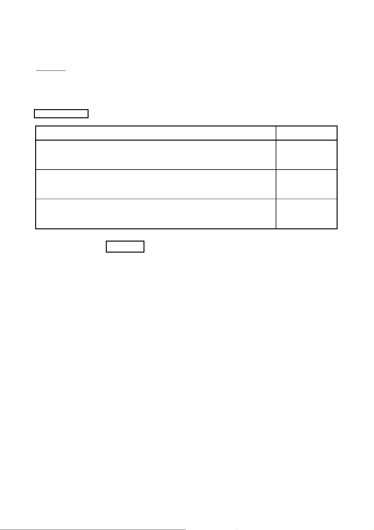
Relevant Manuals
Manual Name
Q Corresponding MELSECNET/H Network System Reference Manual (PLC to PLC network)
This manual explains the system configuration, performance specification, function, handling, wiring and
troubleshooting for MELSECNET/H network system. (Option)
Manual Number
(Model Code)
SH-080049
(13JF92)
For QnA/A4AR MELSECNET/10 Network System Reference Manual
This manual explains the system configuration, performance specification, function, handling, wiring and
troubleshooting for MELSECNET/10 network system. (Option)
MELSEC Data Link Library Reference Manual
This manual explains the programming, function specifications, and sample programming of the
MELSEC data link library. (Option)
REMARK
MELSEC Data Link Library Reference Manual is stored on the CD-ROM of software
package with PDF file.
Manuals in printed form are sold separately for single purchase. Order a manual by
quoting the manual number (model code) listed in the table above.
IB-66690
(13JF78)
SH-081035ENG
(13JV25)
A - 17 A - 17

HOW TO USE THIS MANUAL
"How to Use This Manual" differs depending on the purpose for which the
MELSECNET/H board is used. Use this manual with reference to the following
contents.
(1) When desiring an overview or to know the features of the
(2) When desiring to know about the system configuration
(3) When desiring to know the specifications of the MELSECNET/H
(4) When desiring to know the functions of the MELSECNET/H board
(5) When desiring to know the procedure up to the point of operation
(6) When desiring to know the parameter settings for the
Chapter 7 gives the parameter settings.
(7) When desiring to know the procedure for installing and
(8) When desiring to know the operation of each utility (Chapter 9)
(9) When desiring to know about the MELSEC data link library
MELSECNET/H board (Chapter 1)
Chapter 1 gives an overview of the MELSECNET/H board and its features.
(Chapter 2)
Chapter 2 gives the system configuration.
board (Chapter 3)
Chapter 3 gives the specifications of the MELSECNET/H board.
(Chapter 4)
Chapter 4 gives the functions of the MELSECNET/H board.
of the MELSECNET/H board and settings (Chapter 6)
Chapter 6 gives the procedures up to the point of operation and the settings.
MELSECNET/H board (Chapter 7)
uninstalling the software package (Chapter 8)
Chapter 8 gives the procedure for installing and uninstalling the software
package.
Chapter 9 gives the operation methods for each utility.
(Chapter 10)
Chapter 10 gives overview concerning the MELSEC data link library.
A - 18 A - 18

(10) When desiring to know the interlock related signals (Chapter 11)
Chapter 11 gives the interlock related signals.
(11) When desiring to know the application functions (Chapter 12)
Chapter 12 gives the MELSECNET/H board's application functions.
(12) When desiring to know about troubleshooting (Chapter 14)
Chapter 14 gives information on troubleshooting.
A - 19 A - 19

GENERIC TERMS AND ABBREVIATIONS
Unless otherwise specified, this manual uses the following generic terms and abbreviations to describe
MELSECNET/H interface board.
Generic Term/Abbreviation Description
Q80BD-J71LP21-25 Abbreviation for Q80BD-J71LP21-25 MELSECNET/H interface board.
Q80BD-J71LP21S-25 Abbreviation for Q80BD-J71LP21S-25 MELSECNET/H interface board.
Q80BD-J71LP21G Abbreviation for Q80BD-J71LP21G MELSECNET/H interface board.
Q80BD-J71LP21GE Abbreviation for Q80BD-J71LP21GE MELSECNET/H interface board.
Q80BD-J71BR11 Abbreviation for Q80BD-J71BR11 MELSECNET/H interface board.
Q81BD-J71LP21-25 Abbreviation for Q81BD-J71LP21-25 MELSECNET/H interface board.
MELSECNET/H board
SW0DNC-MNETH-B Product name of the software package for MELSECNET/H interface board.
MNETH utility Abbreviation for MELSECNET/H utility
GX Developer
MX Links
MX Component
MELSECNET/10
ACPU Generic term for the CPU of MELSEC-A series.
QnACPU Generic term for the CPU of MELSEC-QnA series.
QCPU Generic term for the CPU of MELSEC-Q series.
RCPU Generic term for R04CPU, R08CPU, R16CPU, R32CPU, and R120CPU.
QJ71LP21
QJ71BR11 Abbreviation for QJ71BR11 MELSECNET/H network module.
Network module Generic term for QJ71LP21, QJ71BR11
MELSECNET/H Abbreviation for Q corresponding MELSECNET/H network system.
MELSECNET/10 AnU corresponding, QnA/Q4AR corresponding MELSECNET/10 network system.
MELSECNET/H (10 Mbps) Abbreviation in case of using MELSECNET/H board with communication rate of 10 Mbps.
MELSECNET/H (25 Mbps) Abbreviation in case of using MELSECNET/H board with communication rate of 25 Mbps.
MELSECNET/H mode
MELSECNET/H Extended
mode
MELSECNET/10 mode
Board WDT Abbreviation for the watchdog timer that monitors the operation of network board
Driver WDT
Generic term for Q80BD-J71LP21-25, Q81BD-J71LP21-25, Q80BD-J71LP21S-25, Q80BDJ71LP21G, Q80BD-J71LP21GE, and Q80BD-J71BR11.
General product name for product model names SW8D5C-GPPW-E, SW8D5C-GPPW-EA,
SW8D5C-GPPW-EV, and SW8D5C-GPPW-EVA.
General product name for product model names SWnD5F-CSKP-E
(n denotes the version number)
General product name for product model names SWnD5C-ACT-E, SWnD5C-ACT-EA
(n denotes the version number)
Abbreviation for A70BDE-J71QLP23/A70BDE-J71QLP23G E/A70BDE-J71QBR13/A70BDEJ71QLR23 MELSECNET/10 interface board.
Abbreviation for QJ71LP21, QJ71LP21G, Q71LP21GE, QJ71LP21-25, QJ71LP21S-25,
MELSECNET/H network module.
However, if shown for a particular model, QJ71LP21, QJ71LP21G, Q71LP21GE,
QJ71LP21-25, QJ71LP21S-25 is entered.
Abbreviation in case of using MELSECNET/H board and network module with
MELSECNET/H.
Abbreviation for the extended MELSECNET/H mode, which is extended in the maximum
number of link points per station.
Abbreviation in case of using MELSECNET/H board and network module with
MELSECNET/10.
Abbreviation for the watchdog timer that monitors the communication status between a
network board and a personal computer, or operating status of a personal computer
A - 20 A - 20
MEANING AND CONTENTS OF THE TERMS
This section describes meaning and contents of the terms in this manual.
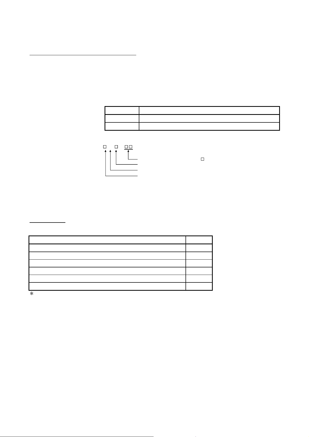
(1) Abbreviations for control station and normal station, and symbol format
This section explains abbreviations for control station and normal station, and
symbol format to be used in this manual.
(a) Abbreviation
Abbreviation Name
MP Control station
NS Normal station (Station that can serve as a control station)
(b) Symbol format
Mp —
Group number (1 to 32) : G
Station number (1 to 64)
Abbreviation
Network No. (1 to 239)
[Example]
P
1) Network No. 3, control station, station number 6: 3M
2) Network No. 5, normal station, station number 3: 5N
6
S
3
PACKING LIST
The packing list of the MELSECNET/H board is given below.
Item Quantity
Board 1
Connector set for external power supply cable(Q80BD-J71LP21S-25 only) 1
F-type connector (A6RCON-F) (Q80BD-J71BR11 only) 1
"Before Using the Product" 1
Software Package (CD-ROM) *1 1
Software license agreement 1
1: Manuals are stored on the CD-ROM in PDF format.
A - 21 A - 21

MEMO
A - 22 A - 22
A
1 OVERVIEW
MELSEC
1 OVERVIEW
1.1 Overview
Personal Computer
MELSECNET/H Board
(Q80BD-J71LP21-25)
This is a manual you read when using the MELSCNET/H board in the MELSECNET/H
mode or MELSECNET/H Extended mode. When using the MELSCNET/H board in
the MELSCNET/H network, refer to "Q Corresponding MELSECNET/H Network
System Reference Manual (PLC to PLC network)". Also, when using the board in the
MELSECNET/10 network system, refer to "For QnA/Q4AR Corresponding
MELSECNET/10 network system reference manual".
The MELSECNET/H is a network system which is used to connect multiple sequencer
modules and personal computers, and is equipped with functions and performance
realized in the MELSECNET/10 for general control of a production line.
In the MELSECNET/H, there is a network system which includes an optical loop
system (communication rates: 10 Mbps, 25 Mbps) and a coaxial bus system
(communications rate: 10 Mbps), enabling large volume communications at high
speeds.
Also, in order to improve the performance of the MELSECNET/10 network and achieve
upward compatibility, MELSECNET/H supports the MELSECNET/ H and
MELSECNET/H Extended modes (high performance, high speed mode) and the
MELSECNET/10 Mode (function compatible and performance compatible mode).
Mode Description
MELSECNET/H mode
MELSECNET/H Extended
mode
MELSECNET/10 mode
GX Developer
Set this mode when all CPUs within the network are QCPUs and
RCPUs.
The maximum number of link points per station has been increased
compared with the MELSECNET/H mode.
In excess of 2000 bytes, a maximum of 35840 bytes can be set.
Set this mode when the system uses many link points per station.
This mode is used to operate the MELSECNET/H board on a
MELSECNET/10 network.
Personal Computer
MELSECNET/H Board
(Q80BD-J71BR11)
MELSECNET /H
QCPU
1 2
MELSECNET/10
Mode
QCPU
MELSECNET /10
1
QCPU
MELSECNET/H
QCPU
1
QCPU
1 2
nU QnA
QCPUQCPU
1: The multiple CPU system compatible network module is for function version B and subsequent products.
2: In the multiple CPU system, a network module that becomes a relay station is the same as the control CPU.
1 - 1 1 - 1
1 OVERVIEW
1
1.2 Features
MELSEC
POINT
(1) For MELSECNET/H, select QCPUs, RCPUs, and Q compatible network
modules.
(2) If QnACPU or ACPU are included in the same network, select MELSECNET/10
mode which is compatible with MELSECNET/10.
(3) All of network modules and MELSECNET/H boards within the same network
must be set to the same mode (network type)
1
.
1: MELSECNET/H mode, MELSECNET/H Extended mode and
MELSECNET/10 mode are available.
The features of the MELSECNET/H board are as shown below.
(1) A personal computer can be incorporated into MELSECNET/H.
By mounting the MELSECNET/H board in a personal computer, the personal
computer can be used as a MELSECNET/H or MELSECNET/10 control station
or normal station.
Board model name Supported network
Q80BD-J71LP21-25
Q81BD-J71LP21-25
Q80BD-J71LP21S-25
Q80BD-J71BR11
Q80BD-J71LP21G
Q80BD-J71LP21GE
MELSECNET/H Mode,
MELSECNET/H Extended Mode
MELSECNET/10 Mode MELSECNET/10 Optical Loop System
MELSECNET/H Mode,
MELSECNET/H Extended Mode
MELSECNET/10 Mode
MELSECNET/H Mode,
MELSECNET/H Extended Mode
MELSECNET/10 Mode MELSECNET/10 Optical Loop System
Mode
MELSECNET/H (10 Mbps / 25 Mbps) Optical
Loop System
MELSECNET/H (10 Mbps) Coaxial Bus
System
MELSECNET/10 Coaxial Bus System
MELSECNET/H (10 Mbps) Optical Loop
System
(2) By adopting the PCI/PCI ExpressRstandard, complicated switch
settings are no longer required.
The system can be used simply by installing the MELSECNET/H board in the
personal computer, then installing the software.
The channel No., station No. and other settings can be carried out easily in the
MNETH Utility.
(3) Compatibility with the previous MELSECNET/10 board’s operations
is maintained.
(a) Upward compatibility of user programs
Since MELSECNET/H board has the same number of the maximum
mountable board and channel number as the previous MELSECNET/10
board, the exiting user programs can be utilized.
(b) Compatible with the GX Developer, MX Links and MX
Component.
It is possible to access the programmable controller CPU using the GX
Developer, MX Links and MX Component from a personal computer where
the MELSECNET/H board is installed.
1 - 2 1 - 2

1 OVERVIEW
MELSEC
(4) Compatible with multiple CPU systems.
By using station designations of logical station No. on the MNETH utility,
MELSECNET/H board is capable of communicating with a multiple CPU system.
(5) Compatible with redundant CPU systems.
Only by specifying whether the destination is a control or standby station using
the user program, access is simply made without considering the current
operating system state of the redundant CPU system.
(6) Compatible with MELSECNET/H Extended mode
The MELSECNET/H Extended mode is the extended MELECNET/H mode,
which is extended in the maximum number of link points per station. With this
mode, the maximum number of link points per station can be set to 2000 bytes or
more, i.e., up to 35840 bytes.
This mode is suitable for the system that needs many number of link points per
station.
(7) Drivers are provided for compatibility with each OS.
Each type of driver is provided, so it is easy to build a system that is compatible
with the user environment.
For details on the compatible operating system, refer to Section 2.5.
(8) User programming functions are provided.
Through MicrosoftRVisual BasicRand MicrosoftRVisual C++Rcompatible
functions, it is possible to carry out remote control of a programmable controller
CPU or read and write to devices, and user programs can be created easily.
1 - 3 1 - 3
1 OVERVIEW
Personal
computer
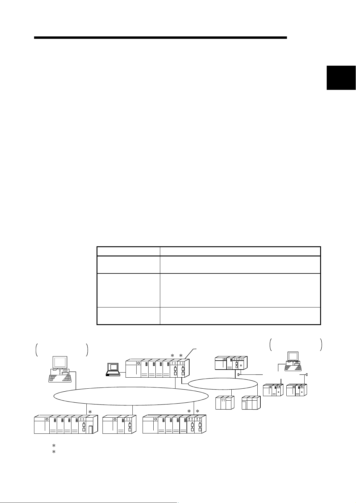
(9) External power supply allows continuous network communication
even during power-off of personal computer. (Function of the
Q80BD-J71LP21S-25)
Since power is supplied externally, the Q80BD-J71LP21S-25 can continue
network communication (baton passing) even if a personal computer is powered
off and data link cannot be performed.
Therefore, a normally operating station connected between other stations with
power-off computers will not be disconnected from the data link.
Another advantage is that the link scan time is stabilized since loopback can be
also prevented.
Personal
computer
Normal station
(Station No.3)
Q80BD
-J71
LP21S
-25
Control station
(Station No.1)
Q80BD
-J71
LP21
-25
Normal station
(Station No.2)
Q
CPU
QJ71
LP21
-25
MELSEC
External power
supply
Personal
computer
Q80BD
-J71
LP21
-25
Normal station
(Station No.6)
Data link continued
Personal
computer
Normal station
(Station No.5)
Q80BD
-J71
LP21S
-25
External power
supply
CPU
Q
Normal station
(Station No.4)
QJ71
LP21
-25
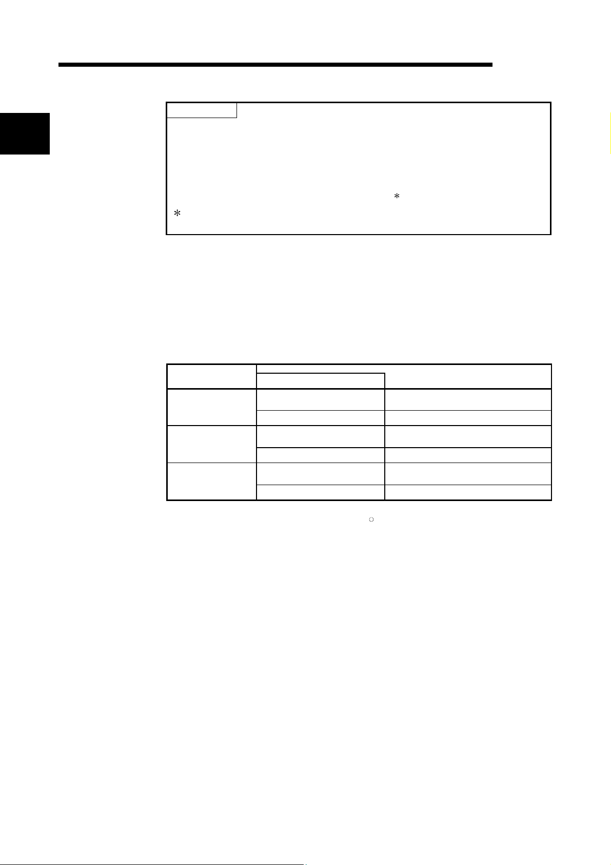
When station No. 3 and No.5 use MELSECNET/H boards without the external
power supply function and if their personal computers are powered off, station
No.4 is cut off from the network as well as No.3 and No.5.
Personal computer
Station No.1 Station No.2 Station No.3
Station No.6 Station No.5 Station No.4
Personal computer
Disconnected
1 - 4 1 - 4
2 SYSTEM CONFIGURATION
MELSEC
2 SYSTEM CONFIGURATION
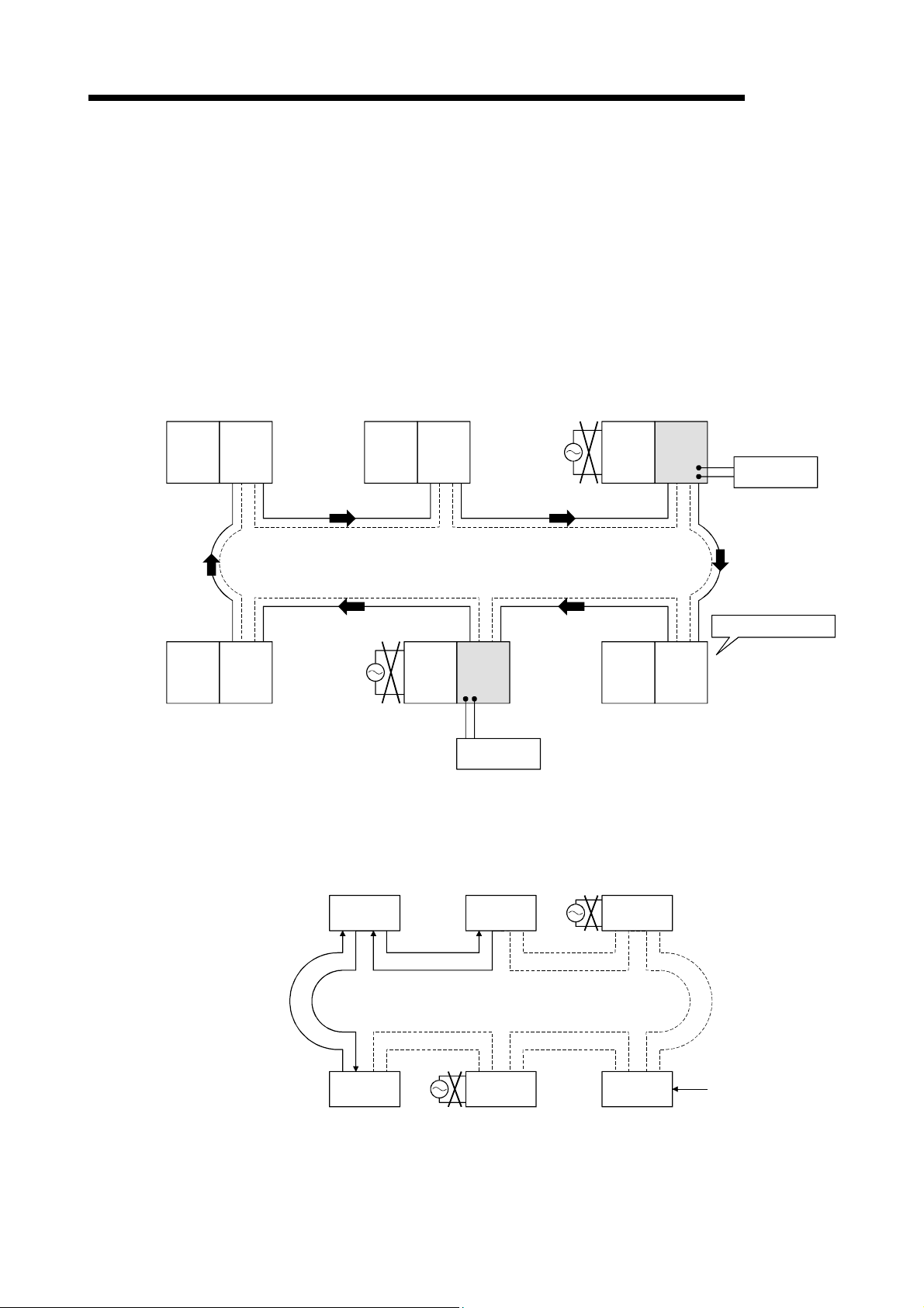
2.1 MELSECNET/H Board System Configuration
The system configuration when the MELSECNET/H board is mounted to a personal
computer is shown below.
Install
Type of cable : SI
Personal Computer
Install
SW0DNC-MNETH-B
Q
80BD-J71LP21-25
Q81BD-J71LP21-25
Q80BD-J71LP21S-25
Q80BD-J71LP21G
Q80BD-J71LP21GE
Optical fiber
cable
H-PCF
Broad-band H-PCF
QSI
Optical fiber
cable
(Type of cable : GI)
Optical fiber
cable
(Type of cable : 62.5GI)
MELSECNET/H
mode,
MELSECNET/H
Extended mode
MELSECNET/10
mode
MELSECNET/H
mode,
MELSECNET/H
Extended mode
MELSECNET/10
mode
MELSECNET/H
mode,
MELSECNET/H
Extended mode
MELSECNET/10
mode
MELSECNET/H
Optical loop system
MELSECNET/10
Optical loop system
MELSECNET/H
Optical loop system
MELSECNET/10
Optical loop system
MELSECNET/H
Optical loop system
MELSECNET/10
Optical loop system
2
MELSECNET/H
mode,
MELSECNET/H
Q80BD-J71BR11
Extended mode
Coaxial cable
Type of cable : 3C-2V
5C-2V
5C-FB
MELSECNET/10
mode
MELSECNET/H
Coaxial bus system
MELSECNET/10
Coaxial bus system
2 - 1 2 - 1
2 SYSTEM CONFIGURATION
2
MELSEC
POINT
(1) When using the MELSECNET/H Extended mode
(a) Use the MELSECNET/H board of ROM version 2X or later and SW0DNC-
(b) When assigning 2000 bytes or more to the number of link points sent by a
(2) When using the Q80BD-J71LP21S-25
Use the SW0DNC-MNETH-B version 12N or later.
(3) When using the Q80BD-J71LP21-25, Q81BD-J71LP21-25 or Q80BD-
J71LP21S-25 at a communication speed of 25Mbps, errors may occur at all
stations if multiple boards with the same network number are installed, or the
operating systems are started up/shut down or the boards are reset
simultaneously on the adjacent personal computers. In this case, set the
communication speed to 10Mbps.
(4) If the QnACPU or ACPU are included in the same network, select
MELSECNET/10 mode which is compatible with MELSECNET/10.
MNETH-B version 11M or later.
station, set all stations including control stations and normal stations to the
MELSECNET/H Extended mode.
2 - 2 2 - 2
 Loading...