

Page 1
Insulation Displacement Connector for
MELSEC-Q Series 32-Point I/O Module
User's Manual
Q6TA32
Thank you for purchasing the Mitsubishi programmable controller
MELSEC-Q series.
Prior to use, please read this and relevant manuals thorougly to fully
understand the product.
MODEL Q6TA32-U-JE
MODEL
CODE
IB(NA)-0800228-F(1806)MEE
© 2002 MITSUBISHI ELECTRIC CORPORATION
13JT92
Page 2
SAFETY PRECAUTIONS
WARNING
Indicates that incorrect handling may cause
hazardous conditions, resulting in death or severe
injury.
Indicates that incorrect handling may cause
hazardous conditions, resulting in minor or moderate
injury or property damage.
CAUTION
(Read these precautions before using this product.)
Before using this product, please read this manual and the relevant manuals
carefully and pay full attention to safety to handle the product correctly.
In this manual, the safety precautions are classified into two levels:
" WARNING" and " CAUTION".
Under some circumstances, failure to observe the precautions given under
" CAUTION" may lead to serious consequences.
Observe the precautions of both levels because they are important for personal
and system safety.
Make sure that the end users read this manual and then keep the manual in a safe
place for future reference.
[DESIGN PRECAUTIONS]
CAUTION
● Do not bunch the control wires or communication cables with the main circuit
or power line, or install them close to each other.
They should be installed 100 mm (3.94 inch) or more from each other.
Otherwise, noise may occur and result in malfunction.
A-1
Page 3
[INSTALLATION PRECAUTIONS]
CAUTION
● Use the programmable controller in an environment that meets the general
specifications given in the user's manual for the CPU module used.
Failure to do so may result in electric shock, fire, malfunction, or damage to or
deterioration of the product.
● When installing this product on an I/O module, securely install it using 2 fixing
screws (M2.6).
Incorrect installation may cause this product to fall out, the I/O module to
malfunction or similar problems to occur.
● Shut off the external power supply for the system in all phases before
mounting or removing this product.
Otherwise, the I/O module may go down or malfunction.
[WIRING PRECAUTIONS]
WARNING
● Shut off the external power supply for the system in all phases before wiring.
Otherwise, an electric shock may occur or this product may be damaged.
CAUTION
● When wiring this product, be sure that the terminal layout is correct and the I/
O module's rated voltage is used. Connecting a power supply out of the rating
or miswiring could result in fire or damage.
● Make sure that the applicable wires are crimped onto the terminal conductors
before using this product.
● Be careful not to let foreign matters such as sawdust or wire chips get inside
this product or the I/O module. These may cause fire, damage, or malfunction.
A-2
Page 4
[STARTING AND MAINTENANCE PRECAUTIONS]
WARNING
● Do not insert or pull out the wires when power is on.
It may cause a malfunction or electric shock.
● Always clean or retighten fixing screws after switching power off externally in
all phases.
Otherwise, the I/O module may malfunction.
CAUTION
● Do not disassemble or rebuild this product.
It may cause accidents, malfunction, injury, or fire.
● Shut off the external power supply for the system in all phases before
mounting or removing this product.
Otherwise, the I/O module may go down or malfunction.
● Before handling the connector, touch a grounded metal object to discharge
the static electricity form the human body.
Failure to do so may cause the module to fail or malfunction.
[DISPOSAL PRECAUTIONS]
CAUTION
● When disposing this product, handle it as industrial waste.
A-3
Page 5

CONDITIONS OF USE FOR THE PRODUCT
(1) Mitsubishi programmable controller ("the PRODUCT") shall be used in
conditions;
i) where any problem, fault or failure occurring in the PRODUCT, if any,
shall not lead to any major or serious accident; and
ii) where the backup and fail-safe function are systematically or
automatically provided outside of the PRODUCT for the case of any
problem, fault or failure occurring in the PRODUCT.
(2) The PRODUCT has been designed and manufactured for the purpose of
being used in general industries.
MITSUBISHI SHALL HAVE NO RESPONSIBILITY OR LIABILITY
(INCLUDING, BUT NOT LIMITED TO ANY AND ALL RESPONSIBILITY
OR LIABILITY BASED ON CONTRACT, WARRANTY, TORT, PRODUCT
LIABILITY) FOR ANY INJURY OR DEATH TO PERSONS OR LOSS OR
DAMAGE TO PROPERTY CAUSED BY the PRODUCT THAT ARE
OPERATED OR USED IN APPLICATION NOT INTENDED OR
EXCLUDED BY INSTRUCTIONS, PRECAUTIONS, OR WARNING
CONTAINED IN MITSUBISHI'S USER, INSTRUCTION AND/OR SAFETY
MANUALS, TECHNICAL BULLETINS AND GUIDELINES FOR the
PRODUCT.
("Prohibited Application")
Prohibited Applications include, but not limited to, the use of the PRODUCT
in;
• Nuclear Power Plants and any other power plants operated by Power
companies, and/or any other cases in which the public could be
affected if any problem or fault occurs in the PRODUCT.
• Railway companies or Public service purposes, and/or any other cases
in which establishment of a special quality assurance system is
required by the Purchaser or End User.
• Aircraft or Aerospace, Medical applications, Train equipment, transport
equipment such as Elevator and Escalator, Incineration and Fuel
devices, Vehicles, Manned transportation, Equipment for Recreation
and Amusement, and Safety devices, handling of Nuclear or
Hazardous Materials or Chemicals, Mining and Drilling, and/or other
applications where there is a significant risk of injury to the public or
property.
A-4
Page 6

Notwithstanding the above, restrictions Mitsubishi may in its sole discretion,
authorize use of the PRODUCT in one or more of the Prohibited
Applications, provided that the usage of the PRODUCT is limited only for
the specific applications agreed to by Mitsubishi and provided further that
no special quality assurance or fail-safe, redundant or other safety features
which exceed the general specifications of the PRODUCTs are required.
For details, please contact the Mitsubishi representative in your region.
A-5
Page 7
REVISIONS
* The manual number is given on the bottom right of the top cover.
Print Date *Manual Number Revision
Feb., 2002 IB(NA)-0800228-A First edition
Jan., 2003 IB(NA)-0800228-B Manual title change
Sep., 2009 IB(NA)-0800228-C SAFETY PRECAUTIONS, Chapter 1, 2, 3,4,
Oct., 2011 IB(NA)-0800228-D SAFETY PRECAUTIONS (Chinese)
May, 2015 IB(NA)-0800228-E Model addition
Jun, 2018 IB(NA)-0800228-F Descriptions are revised due to compliance with the
This manual confers no industrial property rights or any rights of any other kind, nor does it
confer any patent licenses. Mitsubishi electric Corporation cannot be held responsible for any
problems involving industrial property rights which may occur as a result of using the contents
noted in this manual.
Pressure-Displacement Terminal Block Adaptor for
MELSEC-Q Series 32-Point I/O Module
Section 5.2
Chinese standardized law.
A-6
Page 8

CONTENTS
1. OVERVIEW .................................................................................................... 1
2. PERFORMANCE SPECIFICATIONS ............................................................. 2
3. NAMES OF PARTS ........................................................................................ 3
4. HANDLING INSTRUCTIONS ......................................................................... 5
5. WIRING ......................................................................................................... 6
5.1 Wiring Instructions .................................................................................... 6
5.2 External Wiring ......................................................................................... 7
5.3 Wiring Procedure ...................................................................................... 8
6. EXTERNAL DIMENSIONS ........................................................................... 10
A-7
Page 9

MANUALS
The following manual is related to this product.
Please order it if necessary.
Related manual
Manual Name
I/O Module Type Building Block User's Manual
Manual Number
(Model Code)
SH-080042
(13JL99)
A-8
Page 10

Memo
A-9
Page 11

1. OVERVIEW
This manual describes the specifications, handling, part names and
others of the Q6TA32 insulation displacement connector for MELSEC-Q
series 32-point I/O module (hereinafter referred to as the Q6TA32).
The Q6TA32 is to be connected to the connector of the Q Series 40-pin
connector type 32-point I/O module in order to convert the module
connector into an insulation displacement connector.
Q Series I/O module
Packing list
Type Product
Q6TA32 32-point insulation displacement connector
Q6TA32-TOL Wiring tool (sold separately)
Q6TA32
1
Page 12

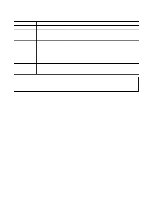
2. PERFORMANCE SPECIFICATIONS
The following table lists the performance specifications of the Q6TA32.
Applicable model QX41, QX41-S1, QX41-S2, QX71, QY41P, QY41H, QY71
Applicable wire
Number of connectable wire 1
Tensile
strength
of wire
Number of wire insertion/
disconnection times
Max. allowable voltage 250VAC
Max. allowable current 3ADC
Contact resistance 100m (327.8 feet) or less
Weight 0.08 kg (0.18 lb.)
*1 Direction of tensile strength of wire
*2 Use the "UL STYLE 1007" or "CSA TYPE TR-64" type cable.
Item Specifications
*2
To the left 35N
*1
Forward 22N
Upward or downward 60N
Polyvinyl chloride wire (twisted wire)
Nominal 0.5 mm2 (20AWG) max. insulation diameter:
1.9 mm (0.07 inch)
LeftForward
30
Upward
Downward
2
Page 13

3. NAMES OF PARTS
2) 3)4)
1)
5)
7)
8)
No. Name Description
1) Line A cover Cover for the insulation displacement connector line A
2) Line B cover Cover for the insulation displacement connector line B
3) Termi nal number (Line A)
4) Termi nal number (Line B)
5) Cover fixing screw Screw for fixing the cover (M2.6 screw)
Insulation displacement
6)
connector fixing screw
7) Connector Connector for connection to the I/O module.
8) Tester lead-in port
Indicate the I/O module pin number A1 to A20 corresponding
to the insulation displacement terminals.
Indicate the I/O module pin number B1 to B20 corresponding
to the insulation displacement terminals.
Screw for fixing the Q6TA32 to the I/O module connector
(M2.6 screw)
Hole through which a tester lead is drawn for continuity
check.
6)
3
Page 14

Memo
4
Page 15

4. HANDLING INSTRUCTIONS
(1) Do not use solid wires with this connector.
(2) Do not drop the connector case and wiring tool or give them high
impact since they are made of resin.
(3) Do not disassemble the connector case.
It may cause a failure.
(4) Tighten the fixing screws and cover fixing screws within the
following ranges.
Insulation displacement connector fixing screw (M2.6 screw) 0.21 to 0.28 N • m
Cover fixing screw (M2.6 screw) 0.21 to 0.28 N • m
(5) When the Q6TA32 is installed to the I/O module, it is 9 mm (0.35
(6) The Q6TA32 cannot be used with any model that is not mentioned
Screw Tightening Torque Range
inch) out of the I/O module bottom. (Refer to "6. OUTLINE
DRAWING".)
Pay attention to the installation position.
as the applicable model in the performance specifications.
5
Page 16
5. WIRING
5.1 Wiring Instructions
(1) Do not strip the insulation of the connectable wire before wiring.
(2) The number of connectable wire per terminal is 1.
(3) Wire the far side line B terminals first.
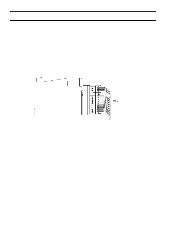
(4) To prevent the wires from pushing the adjacent modules, connect
them after pulling them toward you within the wire's tensile
strength range given in the performance specifications.
I/O module
(5) During and after wiring, do not apply loads larger than the wire's
tensile strength given in the performance specifications to the
wires.
(6) When reusing the wire that has been connected to this connector
once, cut off its insulation displacement end face in advance.
6
Forward
Page 17

5.2 External Wiring
The following table indicates the terminal number and the
corresponding signal name.
(When the head I/O number of the I/O module is set to 0)
Input Module (QX41, QX41-S1, QX41-S2,
Terminal
number
B20 X00 A20 X10 B20 Y00 A20 Y10
B19 X01 A19 X11 B19 Y01 A19 Y11
Signal
name
QX71)
Terminal
number
Signal
name
B18 X02 A18 X12 B18 Y02 A18 Y12
B17 X03 A17 X13 B17 Y03 A17 Y13
B16 X04 A16 X14 B16 Y04 A16 Y14
B15 X05 A15 X15 B15 Y05 A15 Y15
B14 X06 A14 X16 B14 Y06 A14 Y16
B13 X07 A13 X17 B13 Y07 A13 Y17
B12 X08 A12 X18 B12 Y08 A12 Y18
B11 X09 A11 X19 B11 Y09 A11 Y19
B10 X0A A10 X1A B10 Y0A A10 Y1A
B9 X0B A9 X1B B9 Y0B A9 Y1B
B8 X0C A8 X1C B8 Y0C A8 Y1C
B7 X0D A7 X1D B7 Y0D A7 Y1D
B6 X0E A6 X1E B6 Y0 E A6 Y1E
B5 X0F A5 X1 F B5 Y0F A5 Y1F
*2
B4
B3
B2 COM A2 Empty B2 12/24VDC
B1 COM A1 Empty B1 12/24VDC
*1 B1 and B2 of the QY71 are used at 5/12VDC.
*2 The Q6TA32 does not have the terminal number A3, A4, B3 and B4.
*3 B1 and B2 of the QY41H are empty.
-A4 *2-B4 *2-A4 *2-
*2
-A3 *2-B3 *2-A3 *2-
Output Module (QY41P, QY41H, QY71 *1)
Terminal
number
Signal
name
*1*3
*1*3
Terminal
number
A2 COM
A1 COM
Signal
name
7
Page 18

5.3 Wiring Procedure
(1) Wire connection
1) Install the Q6TA32 to the I/O module with the insulation
displacement connector fixing screws, loosen the cover
fixing screws, and remove the covers.
Cover fixing screw
Covers
Wire
Front view
20
19
B
18
17
16
15
14
13
Q6TA32
Q6TA32
I/O module
2) Insert the wire along the guide inside the Q6TA32 without a
gap, push it in gently with your finger to temporarily hold it,
and push it far enough with the wiring tool.
Wiring tool
Wire
Wire
Q6TA32 Q6TA32
Wiring tool
Wire
Wire
I/O moduleI/O module
When wiring Line A (right side), check the numeral of Line
B (left side) to confirm the terminal number to be wired.
8
Page 19
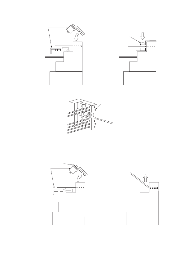
3) Install the covers to the Q6TA32 and tighten the cover
fixing screws.
Covers
Cover fixing screw
Wire
Wire
Q6TA32
Wire
Wire
I/O moduleI/O module
4) Using a tester, make a continuity check.
Tester lead-in port
Wire
Tester lead
(2) Disconnecting the wire
Loosen the cover fixing screws, remove the covers, and pull the
wire toward you.
Cover fixing screw
Covers
Wire
Wire
Q6TA32
Q6TA32
WireWire
Q6TA32
I/O moduleI/O module
9
Page 20
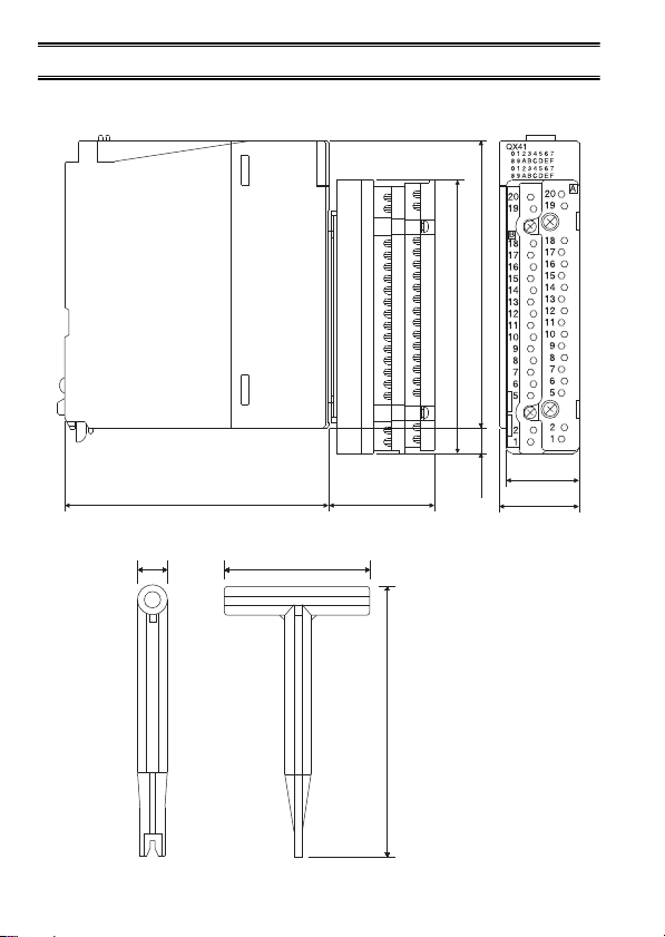
6. EXTERNAL DIMENSIONS
(1) Q6TA32 (When mounted on an I/O module)
(2) Q6TA32-TOL
9.5
(0.37)
50 (1.97)
98 (3.86)
93.5 (3.68)
25 (0.99)
37 (1.46)90 (3.55)
]
9 (0.35)
27.4 (1.08)
93 (3.66)
Unit: mm (inch)
10
Page 21

Memo
11
Page 22
WARRANTY
Mitsubishi will not be held liable for damage caused by factors found not to be the cause of
Mitsubishi; machine damage or lost profits caused by faults in the Mitsubishi products; damage,
secondary damage, accident compensation caused by special factors unpredictable by
Mitsubishi; damages to products other than Mitsubishi products; and to other duties.
Country/
Sales office/
Region
Tel
USA MITSUBISHI ELECTRIC AUTOMATION, INC.
500 Corporate Woods Parkway, Vernon Hills, IL
60061, U.S.A.
Tel : +1-847-478-2100
Mexico MITSUBISHI ELECTRIC AUTOMATION, INC.
Mexico Branch
Mariano Escobedo #69, Col. Zona Industrial,
Tlalnepantla Edo. Mexico, C.P.54030
Tel : +52-55-3067-7500
Brazil MITSUBISHI ELECTRIC DO BRASIL COMÉRCIO
E SERVIÇOS LTDA.
Avenida Adelino Cardana, 293, 21 andar,
Bethaville, Barueri SP, Brazil
Tel : +55-11-4689-3000
Germany MITSUBISHI ELECTRIC EUROPE B.V. German
Branch
Mitsubishi-Electric-Platz 1, 40882 Ratingen,
Germany
Tel : +49-2102-486-0
UK MITSUBISHI ELECTRIC EUROPE B.V. UK Branch
Travellers Lane, Hatfield, Hertfordshire, AL10 8XB,
U.K.
Tel : +44-1707-28-8780
Ireland MITSUBISHI ELECTRIC EUROPE B.V. Irish
Branch
Westgate Business Park, Ballymount, Dublin 24,
Ireland
Tel : +353-1-4198800
Italy MITSUBISHI ELECTRIC EUROPE B.V. Italian
Branch
Centro Direzionale Colleoni-Palazzo Sirio Viale
Colleoni 7, 20864 Agrate Brianza(Milano) Italy
Tel : +39-039-60531
Spain MITSUBISHI ELECTRIC EUROPE, B.V. Spanish
Branch
Carretera de Rubí, 76-80-Apdo. 420, 08190 Sant
Cugat del Vallés (Barcelona), Spain
Tel : +34-935-65-3131
France MITSUBISHI ELECTRIC EUROPE B.V. French
Branch
25, Boulevard des Bouvets, 92741 Nanterre Cedex,
France
Tel : +33-1-55-68-55-68
Czech
MITSUBISHI ELECTRIC EUROPE B.V. Czech
Republic
Branch
Avenir Business Park, Radlicka 751/113e, 158 00
Praha5, Czech Republic
Tel : +420-251-551-470
Poland MITSUBISHI ELECTRIC EUROPE B.V. Polish
Branch
ul. Krakowska 50, 32-083 Balice, Poland
Tel : +48-12-347-65-00
Sweden
MITSUBISHI ELECTRIC EUROPE B.V.
(Scandinavia)
Fjelievägen 8, SE-22736 Lund, Sweden
Tel : +46-8-625-10-00
Russia MITSUBISHI ELECTRIC (RUSSIA) LLC St.
Petersburg Branch
Piskarevsky pr. 2, bld 2, lit “Sch”, BC “Benua”, office
720; 195027 St. Petersburg, Russia
Tel : +7-812-633-3497
HEAD OFFICE : TOKYO BUILDING, 2-7-3 MARUNOUCHI, CHIYODA-KU, TOKYO 100-8310, JAPAN
NAGOYA WORKS : 1-14, YADA-MINAMI 5-CHOME, HIGASHI-KU, NAGOYA, JAPAN
When exported from Japan, this manual does not require application to the Ministry of Economy,
Trade and Industry for service transaction permission.
Sales office/
Country/
Tel
Region
Turkey
MITSUBISHI ELECTRIC TURKEY A.Ş Ümraniye
Branch
Serifali Mahallesi Nutuk Sokak No:5, TR-34775
Umraniye/Istanbul, Turkey
Tel : +90-216-526-3990
UAE
MITSUBISHI ELECTRIC EUROPE B.V. Dubai
Branch
Dubai Silicon Oasis, P.O.BOX 341241, Dubai,
U.A.E.
Tel : +971-4-3724716
South
ADROIT TECHNOLOGIES
Africa
20 Waterford Office Park, 189 Witkoppen Road,
Fourways, South Africa
Tel : +27-11-658-8100
China
MITSUBISHI ELECTRIC AUTOMATION (CHINA)
LTD.
No.1386 Hongqiao Road, Mitsubishi Electric
Automation Center, Shanghai, China
Tel : +86-21-2322-3030
Taiwan
SETSUYO ENTERPRISE CO., LTD.
6F, No.105, Wugong 3rd Road, Wugu District, New
Taipei City 24889, Taiwan
Tel : +886-2-2299-2499
Korea
MITSUBISHI ELECTRIC AUTOMATION KOREA
CO., LTD.
7F-9F, Gangseo Hangang Xi-tower A, 401,
Yangcheon-ro, Gangseo-Gu, Seoul 07528, Korea
Tel : +82-2-3660-9530
Singapore
MITSUBISHI ELECTRIC ASIA PTE. LTD.
307, Alexandra Road, Mitsubishi Electric Building,
Singapore 159943
Tel : +65-6473-2308
Thailand
MITSUBISHI ELECTRIC FACTORY AUTOMATION
(THAILAND) CO., LTD.
12th Floor, SV.City Building, Office Tower 1, No.
896/19 and 20 Rama 3 Road,
Kwaeng Bangpongpang, Khet Yannawa, Bangkok
10120, Thailand
Tel : +66-2682-6522
Vietnam
MITSUBISHI ELECTRIC VIETNAM COMPANY
LIMITED Hanoi Branch
6th Floor, Detech Tower, 8 Ton That Thuyet Street,
My Dinh 2 Ward, Nam Tu Liem District, Hanoi,
Vietnam
Tel : +84-4-3937-8075
Indonesia
PT. MITSUBISHI ELECTRIC INDONESIA
Gedung Jaya 11th Floor, JL. MH. Thamrin No.12,
Jakarta Pusat 10340, Indonesia
Tel : +62-21-3192-6461
India
MITSUBISHI ELECTRIC INDIA PVT. LTD. Pune
Branch
Emerald House, EL-3, J Block, M.I.D.C., Bhosari,
Pune-411026, Maharashtra, India
Tel : +91-20-2710-2000
Australia MITSUBISHI ELECTRIC AUSTRALIA PTY. LTD.
348 Victoria Road, P.O. Box 11, Rydalmere, N.S.W
2116, Australia
Tel : +61-2-9684-7777
Specifications subject to change without notice.
 Loading...