

Page 1

Channel Isolated Thermocouple Input Module
User's Manual
-Q68TD-G-H01
-Q68TD-G-H02
-GX Configurator-TI (SW1D5C-QTIU-E)
Page 2

Page 3
SAFETY PRECAUTIONS
(Read these precautions before using this product.)
Before using this product, please read this manual and the relevant manuals carefully and pay full attention
to safety to handle the product correctly.
In this manual, the safety precautions are classified into two levels: " WARNING" and " CAUTION".
WARNING
CAUTION
Under some circumstances, failure to observe the precautions given under " CAUTION" may lead to
serious consequences.
Observe the precautions of both levels because they are important for personal and system safety.
Make sure that the end users read this manual and then keep the manual in a safe place for future
reference.
Indicates that incorrect handling may cause hazardous conditions,
resulting in death or severe injury.
Indicates that incorrect handling may cause hazardous conditions,
resulting in minor or moderate injury or property damage.
[Design Precautions]
WARNING
Do not write any data to the "system area" of the buffer memory in the intelligent function module.
Also, do not use any "use prohibited" signals as an output signal from the programmable controller
CPU to the intelligent function module.
Doing so may cause malfunction of the programmable controller system.
CAUTION
Do not install the control lines or communication cables together with the main circuit lines or power
cables.
Keep a distance of 100mm (3.94 inches) or more between them.
Failure to do so may result in malfunction due to noise.
A - 1
Page 4
[Installation Precautions]
CAUTION
Use the programmable controller in an environment that meets the general specifications in the
user's manual for the CPU module used.
Failure to do so may result in electric shock, fire, malfunction, or damage to or deterioration of the
product.
To mount the module, while pressing the module mounting lever located in the lower part of the
module, fully insert the module fixing projection(s) into the hole(s) in the base unit and press the
module until it snaps into place.
Incorrect mounting may cause malfunction, failure or drop of the module.
Fix the module to the base unit with a fixing bracket. (Q68TD-G-H02 only)
When using the programmable controller in an environment of frequent vibrations, fix the module
with a module fixing screw. (Q68TD-G-H01 only)
Tighten the screw within the specified torque range.
Undertightening can cause drop of the screw, short circuit or malfunction.
Overtightening can damage the screw and/or module, resulting in drop, short circuit, or malfunction.
Shut off the external power supply (all phases) used in the system before mounting or removing the
module.
Failure to do so may result in damage to the product.
A module can be replaced online (while power is on) on any MELSECNET/H remote I/O station or in
the system where a CPU module supporting the online module change function is used.
Note that there are restrictions on the modules that can be replaced online, and each module has its
predetermined replacement procedure.
For details, refer to the relevant chapter in this manual.
Do not directly touch any conductive parts and electronic components of the module.
Doing so can cause malfunction or failure of the module.
[Wiring Precautions]
CAUTION
Individually ground the shielded cables of the programmable controller with a ground resistance of
Ω or less. Failure to do so may result in electric shock or malfunction.
100
Connectors for external devices must be crimped or pressed with the tool specified by the
manufacturer, or must be correctly soldered.
Incomplete connections may cause short circuit, fire, or malfunction.
Prevent foreign matter such as dust or wire chips from entering the module.
Such foreign matter can cause a fire, failure, or malfunction.
A - 2
Page 5
[Wiring Precautions]
CAUTION
A protective film is attached to the top of the module to prevent foreign matter, such as wire chips,
from entering the module during wiring.
Do not remove the film during wiring.
Remove it for heat dissipation before system operation.
Place the cables in a duct or clamp them.
If not, dangling cable may swing or inadvertently be pulled, resulting in damage to the module or
cables or malfunction due to poor contact.
When disconnecting the cable from the module, do not pull the cable by the cable part.
For the cable with connector, hold the connector part of the cable.
Pulling the cable connected to the module may result in malfunction or damage to the module or
cable.
Keep a distance of 100mm (3.94 inches) or more between a thermocouple and the main circuit line
or AC control lines.
Also, keep the thermocouple away from a circuit that includes harmonics, such as a high-voltage
circuit and a load circuit of an inverter.
Do not place the module near a device that generates magnetic noise.
A - 3
Page 6
[Startup and Maintenance Precautions]
WARNING
Do not touch any terminal while power is on.
Doing so will cause electric shock or malfunction.
Shut off the external power supply (all phases) used in the system before cleaning the module or
retightening the terminal screws, connector screws, or module fixing screws.
Failure to do so may result in electric shock or cause the module to fail or malfunction.
Undertightening can cause drop of the screw, short circuit or malfunction.
Overtightening can damage the screw and/or module, resulting in drop, short circuit, or malfunction.
CAUTION
Do not disassemble or modify the modules.
Doing so may cause failure, malfunction, injury, or a fire.
Shut off the external power supply (all phases) used in the system before mounting or removing the
module.
Failure to do so may cause the module to fail or malfunction.
A module can be replaced online (while power is on) on any MELSECNET/H remote I/O station or in
the system where a CPU module supporting the online module change function is used.
Note that there are restrictions on the modules that can be replaced online, and each module has its
predetermined replacement procedure.
For details, refer to the relevant chapter in this manual.
After the first use of the product, do not mount/remove the module to/from the base unit more than
50 times (IEC 61131-2 compliant).
Exceeding the limit of 50 times may cause malfunction.
Before handling the module, touch a grounded metal object to discharge the static electricity from
the human body.
Failure to do so may cause the module to fail or malfunction.
[Disposal Precautions]
CAUTION
When disposing of this product, treat it as industrial waste.
A - 4
Page 7

CONDITIONS OF USE FOR THE PRODUCT
(1) Mitsubishi programmable controller ("the PRODUCT") shall be used in conditions;
i) where any problem, fault or failure occurring in the PRODUCT, if any, shall not lead to any major
or serious accident; and
ii) where the backup and fail-safe function are systematically or automatically provided outside of
the PRODUCT for the case of any problem, fault or failure occurring in the PRODUCT.
(2) The PRODUCT has been designed and manufactured for the purpose of being used in general
industries.
MITSUBISHI SHALL HAVE NO RESPONSIBILITY OR LIABILITY (INCLUDING, BUT NOT
LIMITED TO ANY AND ALL RESPONSIBILITY OR LIABILITY BASED ON CONTRACT,
WARRANTY, TORT, PRODUCT LIABILITY) FOR ANY INJURY OR DEATH TO PERSONS OR
LOSS OR DAMAGE TO PROPERTY CAUSED BY the PRODUCT THAT ARE OPERATED OR
USED IN APPLICATION NOT INTENDED OR EXCLUDED BY INSTRUCTIONS, PRECAUTIONS,
OR WARNING CONTAINED IN MITSUBISHI'S USER, INSTRUCTION AND/OR SAFETY
MANUALS, TECHNICAL BULLETINS AND GUIDELINES FOR the PRODUCT.
("Prohibited Application")
Prohibited Applications include, but not limited to, the use of the PRODUCT in;
• Nuclear Power Plants and any other power plants operated by Power companies, and/or any
other cases in which the public could be affected if any problem or fault occurs in the PRODUCT.
• Railway companies or Public service purposes, and/or any other cases in which establishment of
a special quality assurance system is required by the Purchaser or End User.
• Aircraft or Aerospace, Medical applications, Train equipment, transport equipment such as
Elevator and Escalator, Incineration and Fuel devices, Vehicles, Manned transportation,
Equipment for Recreation and Amusement, and Safety devices, handling of Nuclear or
Hazardous Materials or Chemicals, Mining and Drilling, and/or other applications where there is a
significant risk of injury to the public or property.
Notwithstanding the above, restrictions Mitsubishi may in its sole discretion, authorize use of the
PRODUCT in one or more of the Prohibited Applications, provided that the usage of the PRODUCT
is limited only for the specific applications agreed to by Mitsubishi and provided further that no
special quality assurance or fail-safe, redundant or other safety features which exceed the general
specifications of the PRODUCTs are required. For details, please contact the Mitsubishi
representative in your region.
A - 5
Page 8

REVISIONS
* The manual number is given on the bottom left of the back cover.
Print Date *Manual Number Revision
Nov., 2008 SH(NA)-080795ENG-A First printing
Sep., 2011 SH(NA)-080795ENG-B
Feb., 2012 SH(NA)-080795ENG-C
Correction
SAFETY PRECAUTIONS, COMPLIANCE WITH EMC AND LOW VOLTAGE
DIRECTIVES, Section 6.2.3, WARRANTY
Addition
CONDTIONS OF USE FOR THE PRODUCT
Correction
SAFETY PRECAUTIONS, GENERIC TERMS, ABBREVIATIONS, AND TERMS,
Chapter 1, Section 1.1, 2.1 to 2.3, 3.1, 3.2, 3.2.1, 3.2.4, 3.3.1, 3.3.2, 3.4.1, 3.4.4,
3.4.5, 3.4.10, 3.4.11, 4.1, 4.3, 4.4.1, 4.4.2, 4.5 to 4.7, 5.2.1, 5.2.2, 5.3.1, 5.4, 5.5,
5.6.1, 5.6.2, 6.2.1, 6.2.2, 6.3.2, 7.1, 7.2, 7.3.1 to 7.3.6, 7.4.1, 7.4.2, 7.5, 8.1,
8.2.9, Appendix 2.2 to 2.4, Appendix 3
Japanese Manual Version SH-080794-D
This manual confers no industrial property rights or any rights of any other kind, nor does it confer any patent licenses.
Mitsubishi Electric Corporation cannot be held responsible for any problems involving industrial property rights which may
occur as a result of using the contents noted in this manual.
© 2008 MITSUBISHI ELECTRIC CORPORATION
A - 6
Page 9

INTRODUCTION
Thank you for purchasing the MELSEC-Q series Programmable Controller.
Before using the equipment, please read this manual carefully to develop full familiarity with the functions
and performance of the Q series Programmable Controller you have purchased, so as to ensure correct
use.
Please forward a copy of this manual to the end user.
CONTENTS
SAFETY PRECAUTIONS•••••••••••••••••••••••••••••••••••••••••••••••••••••••••••••••••••••••••••••••••••••••••••••••••••••• A - 1
CONDITIONS OF USE FOR THE PRODUCT••••••••••••••••••••••••••••••••••••••••••••••••••••••••••••••••••••••••••••• A - 5
REVISIONS•••••••••••••••••••••••••••••••••••••••••••••••••••••••••••••••••••••••••••••••••••••••••••••••••••••••••••••••••••••••A - 6
INTRODUCTION •••••••••••••••••••••••••••••••••••••••••••••••••••••••••••••••••••••••••••••••••••••••••••••••••••••••••••••••• A - 7
CONTENTS••••••••••••••••••••••••••••••••••••••••••••••••••••••••••••••••••••••••••••••••••••••••••••••••••••••••••••••••••••••• A - 7
COMPLIANCE WITH EMC AND LOW VOLTAGE DIRECTIVES ••••••••••••••••••••••••••••••••••••••••••••••••••••• A - 11
GENERIC TERMS, ABBREVIATIONS, AND TERMS •••••••••••••••••••••••••••••••••••••••••••••••••••••••••••••••••• A - 12
PACKING LIST•••••••••••••••••••••••••••••••••••••••••••••••••••••••••••••••••••••••••••••••••••••••••••••••••••••••••••••••••• A - 14
CHAPTER1 OVERVIEW 1 - 1 to 1 - 3
1.1 Features •••••••••••••••••••••••••••••••••••••••••••••••••••••••••••••••••••••••••••••••••••••••••••••••••••••••••••••• 1 - 2
CHAPTER2 SYSTEM CONFIGURATION 2 - 1 to 2 - 9
2.1 Applicable Systems••••••••••••••••••••••••••••••••••••••••••••••••••••••••••••••••••••••••••••••••••••••••••••••••• 2 - 1
2.2 When Using the Q68TD-G-H02 (H01) with Redundant CPU •••••••••••••••••••••••••••••••••••••••••••••• 2 - 6
2.3 How to Check the Function Version, Serial No., and Software Version•••••••••••••••••••••••••••••••••• 2 - 7
CHAPTER3 SPECIFICATIONS 3 - 1 to 3 - 62
3.1 Performance Specifications•••••••••••••••••••••••••••••••••••••••••••••••••••••••••••••••••••••••••••••••••••••••3 - 1
3.2 Function List ••••••••••••••••••••••••••••••••••••••••••••••••••••••••••••••••••••••••••••••••••••••••••••••••••••••••• 3 - 5
3.2.1 Temperature conversion system •••••••••••••••••••••••••••••••••••••••••••••••••••••••••••••••••••••••••••3 - 7
3.2.2 Conversion setting for disconnection detection function (Q68TD-G-H02 only) ••••••••••••••••• 3 - 12
3.2.3 Disconnection state conversion setting function (Q68TD-G-H01 only) ••••••••••••••••••••••••••• 3 - 14
3.2.4 Warning output function•••••••••••••••••••••••••••••••••••••••••••••••••••••••••••••••••••••••••••••••••••• 3 - 16
3.2.5 Cold junction temperature compensation resistor disconnection detection function ••••••••••• 3 - 21
3.3 I/O Signals Transferred to/from Programmable Controller CPU ••••••••••••••••••••••••••••••••••••••••• 3 - 22
3.3.1 I/O signal list ••••••••••••••••••••••••••••••••••••••••••••••••••••••••••••••••••••••••••••••••••••••••••••••••• 3 - 22
3.3.2 I/O signal details••••••••••••••••••••••••••••••••••••••••••••••••••••••••••••••••••••••••••••••••••••••••••••• 3 - 23
3.4 Buffer Memory••••••••••••••••••••••••••••••••••••••••••••••••••••••••••••••••••••••••••••••••••••••••••••••••••••• 3 - 30
3.4.1 Buffer memory assignment•••••••••••••••••••••••••••••••••••••••••••••••••••••••••••••••••••••••••••••••• 3 - 30
3.4.2 Conversion enable/disable setting (Un\G0) •••••••••••••••••••••••••••••••••••••••••••••••••••••••••••• 3 - 38
3.4.3 CH[ ] Time/Count/Moving average/Time constant setting (Un\G1 to Un\G8)•••••••••••••••••••• 3 - 39
3.4.4 Conversion completion flag (Un\G10) ••••••••••••••••••••••••••••••••••••••••••••••••••••••••••••••••••• 3 - 40
3.4.5 CH[ ] Measured temperature value (Un\G11 to Un\G18)•••••••••••••••••••••••••••••••••••••••••••• 3 - 41
A - 7
Page 10

3.4.6 Error code (Un\G19) •••••••••••••••••••••••••••••••••••••••••••••••••••••••••••••••••••••••••••••••••••••••• 3 - 42
3.4.7 Setting range 1, 2 (Thermocouple type) (Un\G20,Un\G21) ••••••••••••••••••••••••••••••••••••••••• 3 - 42
3.4.8 Setting range 3 (Offset/gain setting) (Un\G22) •••••••••••••••••••••••••••••••••••••••••••••••••••••••• 3 - 42
3.4.9 Averaging processing selection (Un\G24,Un\G25) ••••••••••••••••••••••••••••••••••••••••••••••••••• 3 - 43
3.4.10 Offset/gain setting mode (Un\G26,Un\G27)•••••••••••••••••••••••••••••••••••••••••••••••••••••••••••• 3 - 44
3.4.11 CH[ ] Offset/gain temperature setting values (Un\G28 to Un\G43) •••••••••••••••••••••••••••••••• 3 - 45
3.4.12 Cold junction compensation setting status (Un\G45) (Q68TD-G-H02 only) ••••••••••••••••••••• 3 - 45
3.4.13 Warning output enable/disable setting (Un\G46)•••••••••••••••••••••••••••••••••••••••••••••••••••••• 3 - 46
3.4.14 Warning output flag (Process alarm/Rate alarm) (Un\G47,Un\G48) •••••••••••••••••••••••••••••• 3 - 47
3.4.15 Disconnection detection flag (Un\G49) (Q68TD-G-H02 only) •••••••••••••••••••••••••••••••••••••• 3 - 48
3.4.16 Disconnection state monitor flag (Un\G49) (Q68TD-G-H01only) •••••••••••••••••••••••••••••••••• 3 - 50
3.4.17 CH[ ] Scaling value (Un\G50 to Un\G57) ••••••••••••••••••••••••••••••••••••••••••••••••••••••••••••••• 3 - 52
3.4.18 Scaling valid/invalid setting (Un\G58) ••••••••••••••••••••••••••••••••••••••••••••••••••••••••••••••••••• 3 - 53
3.4.19 CH[ ] Scaling range upper/lower limit values (Un\G62 to Un\G77) •••••••••••••••••••••••••••••••• 3 - 54
3.4.20 CH[ ] Scaling width upper/lower limit values (Un\G78 to Un\G93)••••••••••••••••••••••••••••••••• 3 - 55
3.4.21 CH[ ] Process alarm upper/lower limit values (Un\G94 to Un\G125) •••••••••••••••••••••••••••••• 3 - 56
3.4.22 CH[ ] Rate alarm warning detection period (Un\G126 to Un\G133) ••••••••••••••••••••••••••••••• 3 - 57
3.4.23 CH[ ] Rate alarm upper/lower limit values (Un\G134 to Un\G149) •••••••••••••••••••••••••••••••• 3 - 57
3.4.24 Mode switching setting (Un\G158, Un\G159) •••••••••••••••••••••••••••••••••••••••••••••••••••••••••• 3 - 58
3.4.25 Conversion setting for disconnection detection (Un\G164, Un\G165) (Q68TD-G-H02 only)
•••••••••••••••••••••••••••••••••••••••••••••••••••••••••••••••••••••••••••••••••••••••••••••••••••••••••••••••••• 3 - 59
3.4.26 Disconnection state conversion setting (Un\G164, Un\G165) (Q68TD-G-H01only) ••••••••••• 3 - 60
3.4.27 CH[ ] Conversion setting value for disconnection detection (Un\G166 to Un\G173)
(Q68TD-G-H02 only) ••••••••••••••••••••••••••••••••••••••••••••••••••••••••••••••••••••••••••••••••••••••• 3 - 61
3.4.28 CH[ ] Conversion setting value for disconnection state (Un\G166 to Un\G173)
(Q68TD-G-H01only) •••••••••••••••••••••••••••••••••••••••••••••••••••••••••••••••••••••••••••••••••••••••• 3 - 61
3.4.29 Factory default offset/gain values, User range settings offset/gain values (Un\G190 to Un\G253)
•••••••••••••••••••••••••••••••••••••••••••••••••••••••••••••••••••••••••••••••••••••••••••••••••••••••••••••••••• 3 - 62
CHAPTER4 SETUP AND PROCEDURES BEFORE OPERATION 4 - 1 to 4 - 19
4.1 Handling Precautions •••••••••••••••••••••••••••••••••••••••••••••••••••••••••••••••••••••••••••••••••••••••••••••• 4 - 1
4.1.1 Fixing module with module fixing bracket (Q68TD-G-H02 only) ••••••••••••••••••••••••••••••••••••• 4 - 2
4.2 Setup and Procedures before Operation •••••••••••••••••••••••••••••••••••••••••••••••••••••••••••••••••••••••4 - 3
4.3 Part Names ••••••••••••••••••••••••••••••••••••••••••••••••••••••••••••••••••••••••••••••••••••••••••••••••••••••••••4 - 4
4.4 Wiring •••••••••••••••••••••••••••••••••••••••••••••••••••••••••••••••••••••••••••••••••••••••••••••••••••••••••••••••••4 - 7
4.4.1 Wiring precautions ••••••••••••••••••••••••••••••••••••••••••••••••••••••••••••••••••••••••••••••••••••••••••••4 - 7
4.4.2 External wiring ••••••••••••••••••••••••••••••••••••••••••••••••••••••••••••••••••••••••••••••••••••••••••••••••• 4 - 8
4.5 Switch Setting for Intelligent Function Module •••••••••••••••••••••••••••••••••••••••••••••••••••••••••••••• 4 - 10
4.6 Offset/Gain Setting ••••••••••••••••••••••••••••••••••••••••••••••••••••••••••••••••••••••••••••••••••••••••••••••• 4 - 12
4.7 Cold Junction Temperature Compensation with/without Setting •••••••••••••••••••••••••••••••••••••••• 4 - 18
CHAPTER5 UTILITY PACKAGE (GX Configurator-TI) 5 - 1 to 5 - 24
5.1 Utility Package Functions ••••••••••••••••••••••••••••••••••••••••••••••••••••••••••••••••••••••••••••••••••••••••• 5 - 1
5.2 Installing and Uninstalling the Utility Package ••••••••••••••••••••••••••••••••••••••••••••••••••••••••••••••••• 5 - 3
5.2.1 Handling precautions •••••••••••••••••••••••••••••••••••••••••••••••••••••••••••••••••••••••••••••••••••••••••5 - 3
5.2.2 Operating environment ••••••••••••••••••••••••••••••••••••••••••••••••••••••••••••••••••••••••••••••••••••••• 5 - 5
5.3 Utility Package Operation ••••••••••••••••••••••••••••••••••••••••••••••••••••••••••••••••••••••••••••••••••••••••• 5 - 7
A - 8
Page 11

5.3.1 Common utility package operations ••••••••••••••••••••••••••••••••••••••••••••••••••••••••••••••••••••••• 5 - 7
5.3.2 Operation overview •••••••••••••••••••••••••••••••••••••••••••••••••••••••••••••••••••••••••••••••••••••••••••5 - 9
5.3.3 Starting the Intelligent function module utility •••••••••••••••••••••••••••••••••••••••••••••••••••••••••• 5 - 11
5.4 Initial Setting ••••••••••••••••••••••••••••••••••••••••••••••••••••••••••••••••••••••••••••••••••••••••••••••••••••••• 5 - 13
5.5 Auto Refresh Settings•••••••••••••••••••••••••••••••••••••••••••••••••••••••••••••••••••••••••••••••••••••••••••• 5 - 15
5.6 Monitoring/Test •••••••••••••••••••••••••••••••••••••••••••••••••••••••••••••••••••••••••••••••••••••••••••••••••••• 5 - 18
5.6.1 Monitor/test screen•••••••••••••••••••••••••••••••••••••••••••••••••••••••••••••••••••••••••••••••••••••••••• 5 - 18
5.6.2 Offset/gain setting operation •••••••••••••••••••••••••••••••••••••••••••••••••••••••••••••••••••••••••••••• 5 - 21
5.6.3 OMC (Online Module Change) refresh data ••••••••••••••••••••••••••••••••••••••••••••••••••••••••••• 5 - 24
CHAPTER6 PROGRAMMING 6 - 1 to 6 - 27
6.1 Programming Procedure •••••••••••••••••••••••••••••••••••••••••••••••••••••••••••••••••••••••••••••••••••••••••• 6 - 2
6.2 Using Programs in Normal System Configuration ••••••••••••••••••••••••••••••••••••••••••••••••••••••••••••6 - 4
6.2.1 Before creating a program••••••••••••••••••••••••••••••••••••••••••••••••••••••••••••••••••••••••••••••••••• 6 - 5
6.2.2 Program example when Configurator-TI•••••••••••••••••••••••••••••••••••••••••••••••••••••••••••••••••• 6 - 7
6.2.3 Program example when GX Configurator-TI is not used •••••••••••••••••••••••••••••••••••••••••••• 6 - 12
6.3 Using Programs on Remote I/O Network •••••••••••••••••••••••••••••••••••••••••••••••••••••••••••••••••••• 6 - 15
6.3.1 Before creating a program••••••••••••••••••••••••••••••••••••••••••••••••••••••••••••••••••••••••••••••••• 6 - 17
6.3.2 Program example when GX Configurator-TI is used ••••••••••••••••••••••••••••••••••••••••••••••••• 6 - 18
6.3.3 Program example when GX Configurator-TI is not used •••••••••••••••••••••••••••••••••••••••••••• 6 - 22
CHAPTER7 ONLINE MODULE CHANGE 7 - 1 to 7 - 37
7.1 Online Module Change Conditions •••••••••••••••••••••••••••••••••••••••••••••••••••••••••••••••••••••••••••••• 7 - 2
7.2 Online Module Change Operations••••••••••••••••••••••••••••••••••••••••••••••••••••••••••••••••••••••••••••••7 - 3
7.3 Online Module Change Procedure ••••••••••••••••••••••••••••••••••••••••••••••••••••••••••••••••••••••••••••••7 - 4
7.3.1 When factory default is used and initial setting was made with GX Configurator-TI ••••••••••••• 7 - 4
7.3.2 When factory default is used and initial setting was made with sequence program •••••••••••••7 - 9
7.3.3 When user range setting is used and initial setting was made with GX Configurator-TI
(other system is available)••••••••••••••••••••••••••••••••••••••••••••••••••••••••••••••••••••••••••••••••• 7 - 13
7.3.4 When user range setting is used and initial setting was made with GX Configurator-TI
(other system is unavailable) ••••••••••••••••••••••••••••••••••••••••••••••••••••••••••••••••••••••••••••• 7 - 18
7.3.5 When user range setting is used and initial setting was made with sequence program
(other system is available)••••••••••••••••••••••••••••••••••••••••••••••••••••••••••••••••••••••••••••••••• 7 - 23
7.3.6 When user range setting is used and initial setting was made with sequence program
(other system is unavailable) ••••••••••••••••••••••••••••••••••••••••••••••••••••••••••••••••••••••••••••• 7 - 28
7.4 Range Reference Table ••••••••••••••••••••••••••••••••••••••••••••••••••••••••••••••••••••••••••••••••••••••••• 7 - 33
7.4.1 Range reference table (Q68TD-G-H02) •••••••••••••••••••••••••••••••••••••••••••••••••••••••••••••••• 7 - 33
7.4.2 Range reference table (Q68TD-G-H01) •••••••••••••••••••••••••••••••••••••••••••••••••••••••••••••••• 7 - 35
7.5 Precautions for Online Module Change •••••••••••••••••••••••••••••••••••••••••••••••••••••••••••••••••••••• 7 - 37
CHAPTER8 TROUBLESHOOTING 8 - 1 to 8 - 8
8.1 Error Code List •••••••••••••••••••••••••••••••••••••••••••••••••••••••••••••••••••••••••••••••••••••••••••••••••••••• 8 - 1
8.2 Troubleshooting •••••••••••••••••••••••••••••••••••••••••••••••••••••••••••••••••••••••••••••••••••••••••••••••••••••8 - 4
8.2.1 "RUN" LED is extinguished•••••••••••••••••••••••••••••••••••••••••••••••••••••••••••••••••••••••••••••••••• 8 - 4
8.2.2 "RUN" LED flickers•••••••••••••••••••••••••••••••••••••••••••••••••••••••••••••••••••••••••••••••••••••••••••• 8 - 4
A - 9
Page 12

8.2.3 "ERR" LED flickers •••••••••••••••••••••••••••••••••••••••••••••••••••••••••••••••••••••••••••••••••••••••••••• 8 - 4
8.2.4 "ERR" LED is lit •••••••••••••••••••••••••••••••••••••••••••••••••••••••••••••••••••••••••••••••••••••••••••••••• 8 - 4
8.2.5 "ALM" LED flickers •••••••••••••••••••••••••••••••••••••••••••••••••••••••••••••••••••••••••••••••••••••••••••• 8 - 5
8.2.6 "ALM" LED is lit •••••••••••••••••••••••••••••••••••••••••••••••••••••••••••••••••••••••••••••••••••••••••••••••• 8 - 5
8.2.7 When Disconnection detection signal (XC) (Q68TD-G-H02 only) or Disconnection state monitor
signal (XC) (Q68TD-G-H01 only) turns on •••••••••••••••••••••••••••••••••••••••••••••••••••••••••••••••8 - 5
8.2.8 Measured temperature value cannot be read•••••••••••••••••••••••••••••••••••••••••••••••••••••••••••• 8 - 5
8.2.9 Measured temperature value is abnormal •••••••••••••••••••••••••••••••••••••••••••••••••••••••••••••••• 8 - 6
8.2.10 Checking the Q68TD-G-H02(H01) status using GX Developer system monitor•••••••••••••••••• 8 - 7
APPENDICES APPX - 1 to APPX - 15
Appendix 1 Differences of Q68TD-G-H02, Q68TD-G-H01, Q64TD, Q64TDV-GH •••••••••••••••••••••APPX - 1
Appendix 2 Dedicated Instruction ••••••••••••••••••••••••••••••••••••••••••••••••••••••••••••••••••••••••••••••••APPX - 2
Appendix 2.1 Dedicated Instruction List and Available Device•••••••••••••••••••••••••••••••••••••••••APPX - 2
Appendix 2.2 G(P).OFFGAN •••••••••••••••••••••••••••••••••••••••••••••••••••••••••••••••••••••••••••••••••APPX - 3
Appendix 2.3 G(P).OGLOAD ••••••••••••••••••••••••••••••••••••••••••••••••••••••••••••••••••••••••••••••••• APPX - 5
Appendix 2.4 G(P).OGSTOR •••••••••••••••••••••••••••••••••••••••••••••••••••••••••••••••••••••••••••••••••APPX - 9
Appendix 3 External Dimension Diagram •••••••••••••••••••••••••••••••••••••••••••••••••••••••••••••••••••• APPX - 14
INDEX INDEX - 1 to INDEX - 2
A - 10
Page 13

COMPLIANCE WITH EMC AND LOW VOLTAGE DIRECTIVES
(1) Method of ensuring compliance
To ensure that Mitsubishi programmable controllers maintain EMC and Low Voltage
Directives when incorporated into other machinery or equipment, certain measures
may be necessary. Please refer to one of the following manuals.
• QCPU User's Manual (Hardware Design, Maintenance and Inspection)
• Safety Guidelines
(This manual is included with the CPU module or base unit.)
(2) Additional measures
To ensure that this product maintains EMC and Low Voltage Directives, please refer
to Section 4.4.1.
A - 11
Page 14
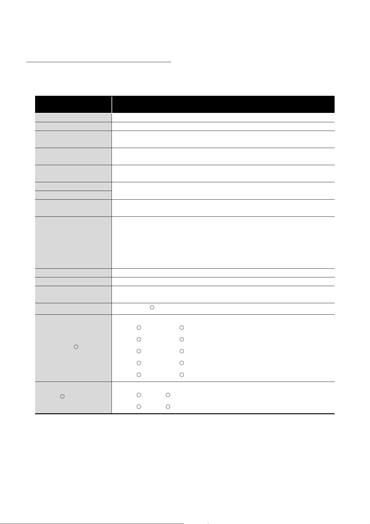
GENERIC TERMS, ABBREVIATIONS, AND TERMS
Unless otherwise specified, this manual uses the following general terms, abbreviations,
and terms.
Generic term/
Abbreviation/Term
Description
Q68TD-G-H02 The abbreviation for the Q68TD-G-H02 channel isolated thermocouple input module
Q68TD-G-H01 The abbreviation for the Q68TD-G-H01 channel isolated thermocouple input module
Q68TD-G-H02(H01)
Up scale
Down scale
GX Developer
GX Works2
GX Configurator-TI
The abbreviation for the Q68TD-G-H02 or Q68TD-G-H01 channel isolated thermocouple
input module
The maximum value in measured temperature range plus 5% value of measured
temperature range
The minimum value in measured temperature range minus 5% value of measured
temperature range
The product name of the software package for the MELSEC programmable controllers
The abbreviation for the thermocouple input module setting and monitor tool GX
Configurator-TI (SW1D5C-QTIU-E)
A generic term for the Q00JCPU, Q00CPU, Q01CPU, Q02CPU, Q02HCPU, Q06HCPU,
Q12HCPU, Q25HCPU, Q02PHCPU, Q06PHCPU, Q12PHCPU, Q25PHCPU,
QCPU (Q mode)
Q12PRHCPU, Q25PRHCPU, Q00UJCPU, Q00UCPU, Q01UCPU, Q02UCPU,
Q03UDCPU, Q04UDHCPU, Q06UDHCPU, Q10UDHCPU, Q13UDHCPU, Q26UDHCPU,
Q20UDHCPU, Q03UDECPU, Q04UDEHCPU, Q06UDEHCPU, Q10UDEHCPU,
Q13UDEHCPU, Q20UDEHCPU, Q26UDEHCPU, Q50UDEHCPU, and Q100UDEHCPU
Redundant CPU A generic term for the Q12PRHCPU and Q25PRHCPU
Process CPU A generic term for the Q02PHCPU, Q06PHCPU, Q12PHCPU, and Q25PHCPU
Cold junction temperature
compensation resistor
Personal computer
A generic term for resistance temperature detectors (RTD) used for cold junction
temperature compensation. Pt100 is used.
An IBM PC/AT or compatible computer with DOS/V
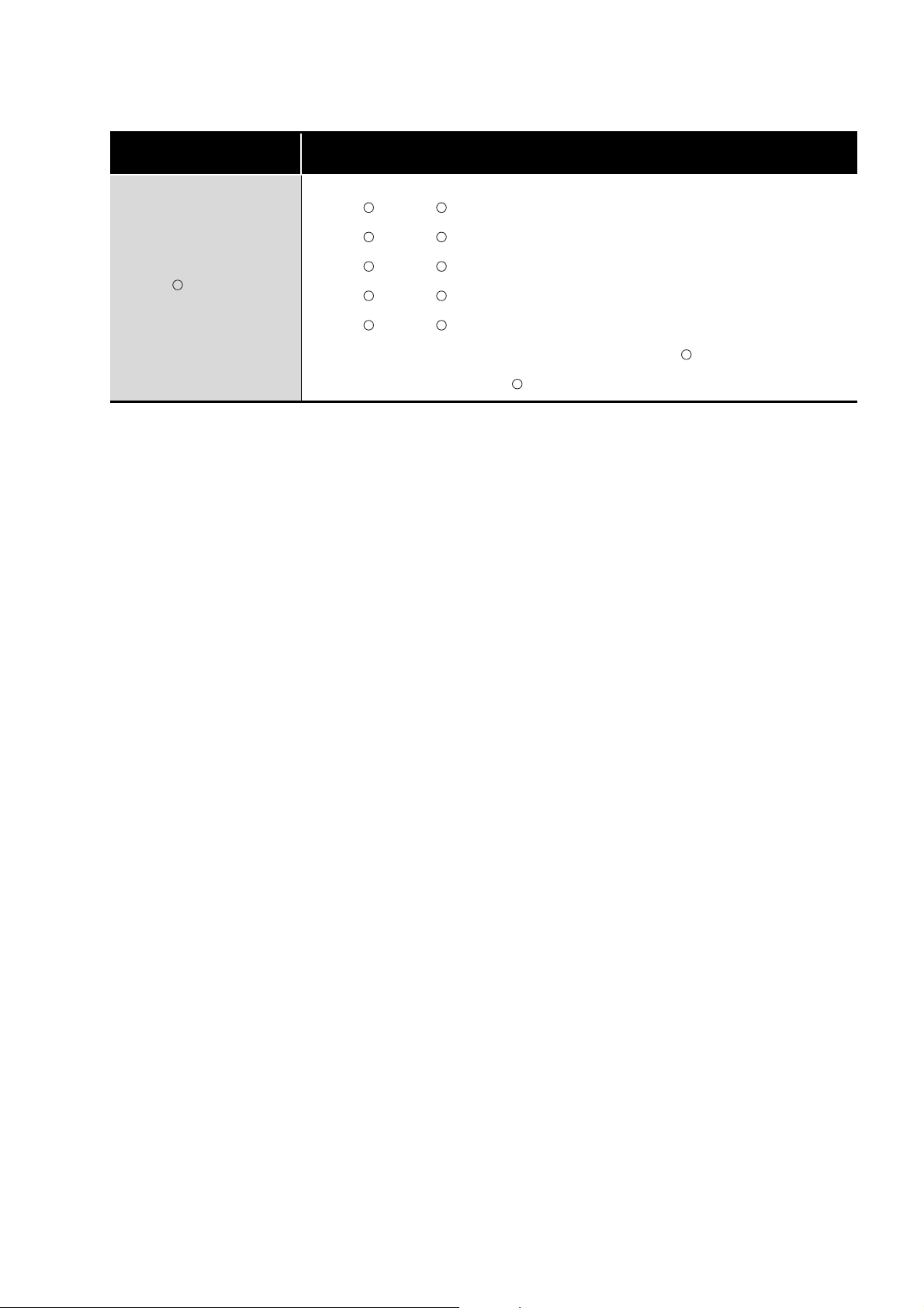
R
A generic term for the following:
R R
R R
R R
R R
R R
Windows Vista
Microsoft Windows Vista Home Basic Operating System,
R
Microsoft Windows Vista Home Premium Operating System,
Microsoft Windows Vista Business Operating System,
Microsoft Windows Vista Ultimate Operating System,
Microsoft Windows Vista Enterprise Operating System
A generic term for the following:
Windows XP
R
Microsoft Windows XP Professional Operating System,
Microsoft Windows XP Home Edition Operating System
R R
R R
A - 12
Page 15
Generic term/
Abbreviation/Term
Windows 7
R
Description
A generic term for the following:
Microsoft Windows 7 Starter Operating System,
Microsoft Windows 7 Home Premium Operating System,
Microsoft Windows 7 Professional Operating System,
Microsoft Windows 7 Ultimate Operating System,
Microsoft Windows 7 Enterprise Operating System
Note that the 32-bit version is designated as "32-bit Windows 7", and the 64-bit version
is designated as "64-bit Windows 7".
R R
R R
R R
R R
R R
R
R
A - 13
Page 16
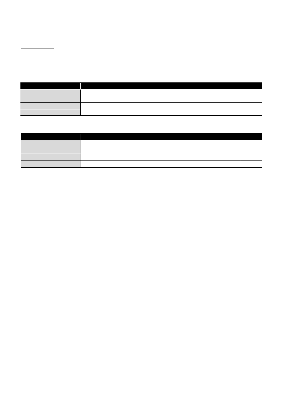
PACK I NG LIST
The product package contains the following.
(1) Q68TD-G-H02
Model Product Quantity
Q68TD-G-H02
SW1D5C-QTIU-E GX Configurator-TI Version 1 (Single license product) (CD-ROM) 1
SW1D5C-QTIU-EA GX Configurator-TI Version 1 (Volume license product) (CD-ROM) 1
Q68TD-G-H02 channel isolated thermocouple input module 1
Cold junction temperature compensation resistor (RTD) 1
(2) Q68TD-G-H01
Model Product Quantity
Q68TD-G-H01
SW1D5C-QTIU-E GX Configurator-TI Version 1 (Single license product) (CD-ROM) 1
SW1D5C-QTIU-EA GX Configurator-TI Version 1 (Volume license product) (CD-ROM) 1
Q68TD-G-H01 channel isolated thermocouple input module 1
Cold junction temperature compensation resistor (RTD) 1
A - 14
Page 17
1
OVERVIEW
CHAPTER1 OVERVIEW
This user's manual provides the specifications, handling instructions, programming
procedures and other information of the Q68TD-G-H02 or Q68TD-G-H01 channel isolated
thermocouple input module (hereafter abbreviated as Q68TD-G-H02 (H01)), which is
designed to use with the MELSEC-Q series CPU module (referred to as the
programmable controller CPU).
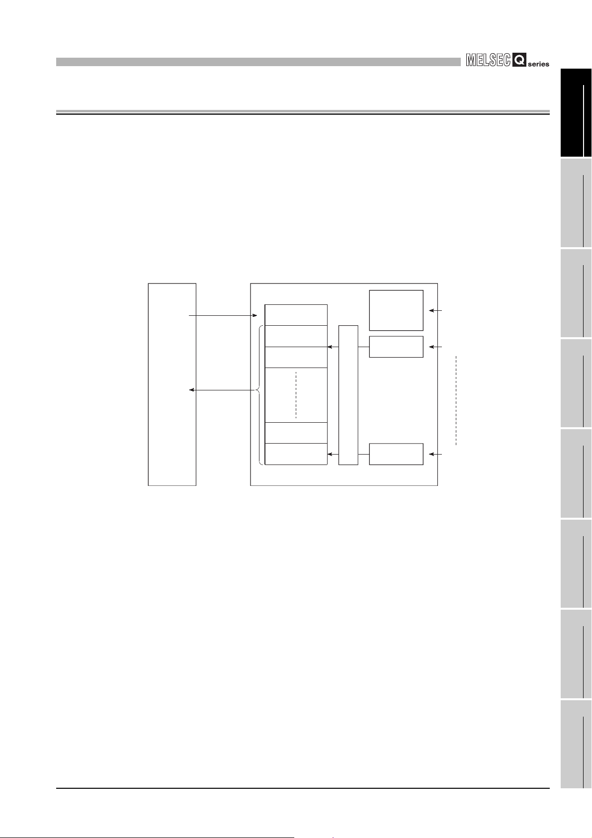
The Q68TD-G-H02(H01) is a module designed to convert thermocouple input values from
outside the programmable controller into 16-bit signed binary measured temperature
values and 16-bit signed binary scaling values (ratios).
Programmable
controller CPU
Q68TD-G-H02(H01)
1
2
3
OVERVIEW
SYSTEM
CONFIGURATION
TO
instruction
FROM
instruction
(Buffer memory)
Initial setting
Measured
temperature value,
scaling value
reading
Figure 1.1 Overview of Q68TD-G-H02(H01)
* 1 Refer to Section 3.4.17 for details of the scaling values.
Set data
Measured
temperature value
Scaling value
Measured
temperature value
Scaling value
1
*
1
*
Cold junction
temperature
compensation
channel
Channel 1
Temperature measurement
Channel 8
Resistance temperature
detector input
(by cold junction temperature
compensation resistor (RTD))
Thermocouple input
Thermocouple input
SPECIFICATIONS
4
SETUP AND
PROCEDURES BEFORE
OPERATION
5
UTILITY PACKAGE (GX
CONFIGURATOR-TI)
6
1 - 1
PROGRAMMING
7
ONLINE MODULE
CHANGE
8
TROUBLESHOOTING
Page 18

1
OVERVIEW
1.1 Features
(1) Channels isolated
Q68TD-G-H02(H01) is channel isolated modules.
(2) 8 channels of temperatures measured by one module
One Q68TD-G-H02(H01) module can measure temperatures of 8 channels.
It can also convert the detected temperature values into scaling values (ratios (%)).
(3) Setting of conversion enable/disable
Conversion enable/disable setting for each channel is possible. Disabling conversion
for unused channels prevents unnecessary disconnection detection or monitor of
disconnection state on unused channels.
(4) Use of thermocouples conforming to JIS or IEC standards
Eight types of thermocouple (K, E, J, T, B, R, S, N) conforming to JIS or IEC standards
can be used.
A thermocouple type can be selected for each channel.
(5) Disconnection detection function (Q68TD-G-H02 only)
Disconnection status of thermocouple or compensating lead wire can be detected for
each channel by Disconnection detection flag.
Disconnection status can also be detected from the measured temperature value by
setting "Up scale", "Down scale" or "Given value" for the Conversion setting for
disconnection detection.
(6) Disconnection monitor function (Q68TD-G-H01 only)
Disconnection status of thermocouple or compensating lead wire can be checked on
each channel by Disconnection state monitor flag.
Disconnection status can also be checked from the measured temperature value by
setting "Up scale", "Down scale" or "Given value" for the Conversion setting for
disconnection detection.
(7) Selection of sampling processing, time average processing, count
average processing, moving average processing, and primary delay
filter
As a conversion processing method, sampling processing, time average processing,
count average processing, moving average or primary delay filter can be selected for
each channel.
1 - 2
(8) Cold junction temperature compensation by cold junction temperature
compensation resistor (RTD)
Cold junction temperature compensation is possible by connecting the supplied cold
junction temperature compensation resistor (RTD) and enabling the cold junction
temperature compensation.
Resistance temperature detector Pt100 is used for cold junction temperature
compensation resistor (RTD).
1.1 Features
Page 19

1
OVERVIEW
(9) Error compensation by offset/gain value setting
Error compensation can be made by setting offset and gain values on each channel.
As the offset and gain values, you can make selection from user range setting and
factory default setting.
(10)Warning output function
(a) Process alarm warning output
(b) Rate alarm warning output
A warning can be output when the input range set by the user is exceeded.
Upper limit value and lower limit value can be set for each channel, and a setting
to have a difference (hysteresis) between warning output and warning clear is
also possible.
By setting a changing rate, a warning can be output when the changing rate is
exceeded.
1
2
3
OVERVIEW
SYSTEM
CONFIGURATION
(11)Online module change
The module can be changed without stopping the system.
Furthermore, the following operations can be processed by using sequence
programs.
• Transferring the offset/gain set values to the replacement Q68TD-G-H02 (H01)
• Transferring the offset/and gain set values to another Q68TD-G-H02 (H01)
mounted on the other slot
(12)Easy settings using GX Configurator-TI
Using GX Configurator-TI which is sold separately, sequence programs can be
reduced since settings of the Q68TD-G-H02 (H01) can be made on the screen.
Also, the set status or operating status of the module can be checked easily.
SPECIFICATIONS
4
SETUP AND
PROCEDURES BEFORE
OPERATION
5
UTILITY PACKAGE (GX
CONFIGURATOR-TI)
6
PROGRAMMING
7
1.1 Features
1 - 3
ONLINE MODULE
CHANGE
8
TROUBLESHOOTING
Page 20

2
SYSTEM CONFIGURATION
CHAPTER2 SYSTEM CONFIGURATION
This chapter explains the system configuration of the Q68TD-G-H02 (H01).
2.1 Applicable Systems
This section describes applicable systems.
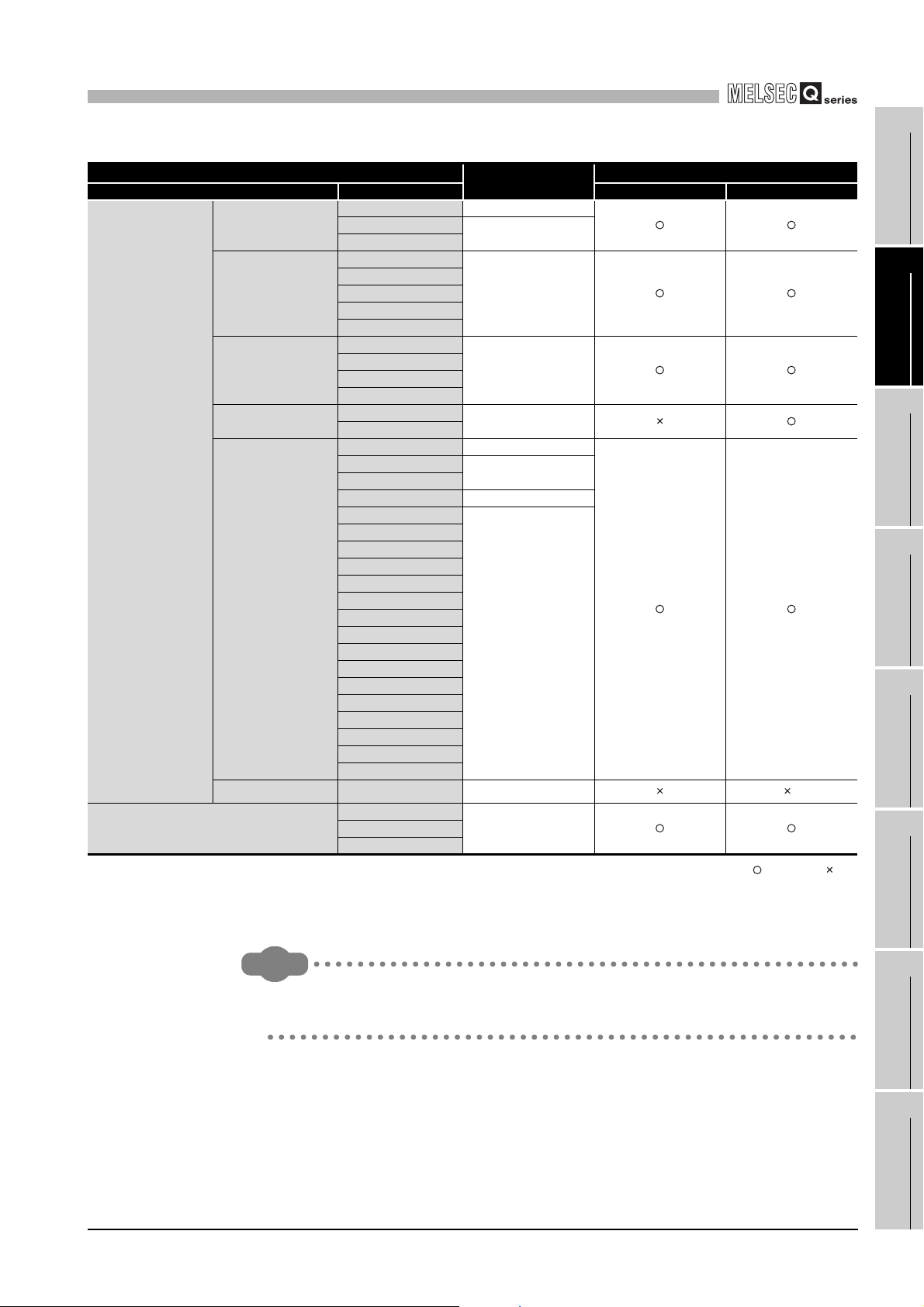
(1) Applicable modules and base units, and No. of modules
(a) When mounted with a CPU module
The table below shows the CPU modules and base units applicable to the
Q68TD-G-H02 (H01) and quantities for each CPU model.
Depending on the combination with other modules or the number of mounted
modules, power supply capacity may be insufficient.
Pay attention to the power supply capacity before mounting modules, and if the
power supply capacity is insufficient, change the combination of the modules.
2 - 1
2.1 Applicable Systems
Page 21
2
SYSTEM CONFIGURATION
Programmable
controller CPU
C Controller module
Table 2.1 Applicable modules, number of mountable modules, and applicable base units
Applicable CPU module
CPU type CPU model Main base unit Extension base unit
Q00JCPU Up to 16
Basic model QCPU
High Performance
model QCPU
Process CPU
Redundant CPU
Universal model QCPU
Safety CPU QS001CPU N/A
* 1 Limited within the range of I/O points for the CPU module.
* 2 Restrictions apply to mountable slot position. (Refer to (2) in this section)
* 3 An extension base unit cannot be connected to a safety CPU.
Q00CPU
Q01CPU
Q02CPU
Q02HCPU
Q06HCPU
Q12HCPU
Q25HCPU
Q02PHCPU
Q06PHCPU
Q12PHCPU
Q25PHCPU
Q12PRHCPU
Q25PRHCPU
Q00UJCPU Up to 16
Q00UCPU
Q01UCPU
Q02UCPU Up to 36
Q03UDCPU
Q04UDHCPU
Q06UDHCPU
Q10UDHCPU
Q13UDHCPU
Q20UDHCPU
Q26UDHCPU
Q03UDECPU
Q04UDEHCPU
Q06UDEHCPU
Q10UDHCPU
Q13UDEHCPU
Q20UDEHCPU
Q26UDEHCPU
Q50UDEHCPU
Q100UDEHCPU
Q06CCPU-V
Q06CCPU-V-B
Q12DCCPU-V
No. of modules
Up to 24
Up to 64
Up to 64
Up to 53
Up to 24
Up to 64
Up to 64
*1
Applicable base unit
*2
*3
:Applicable, :N/A
Remark
To use the Q68TD-G-H02 (H01) with a C Controller module, refer to the user's
manual for the C Controller module.
1
OVERVIEW
2
SYSTEM
CONFIGURATION
3
SPECIFICATIONS
4
SETUP AND
PROCEDURES BEFORE
OPERATION
5
UTILITY PACKAGE (GX
CONFIGURATOR-TI)
6
PROGRAMMING
7
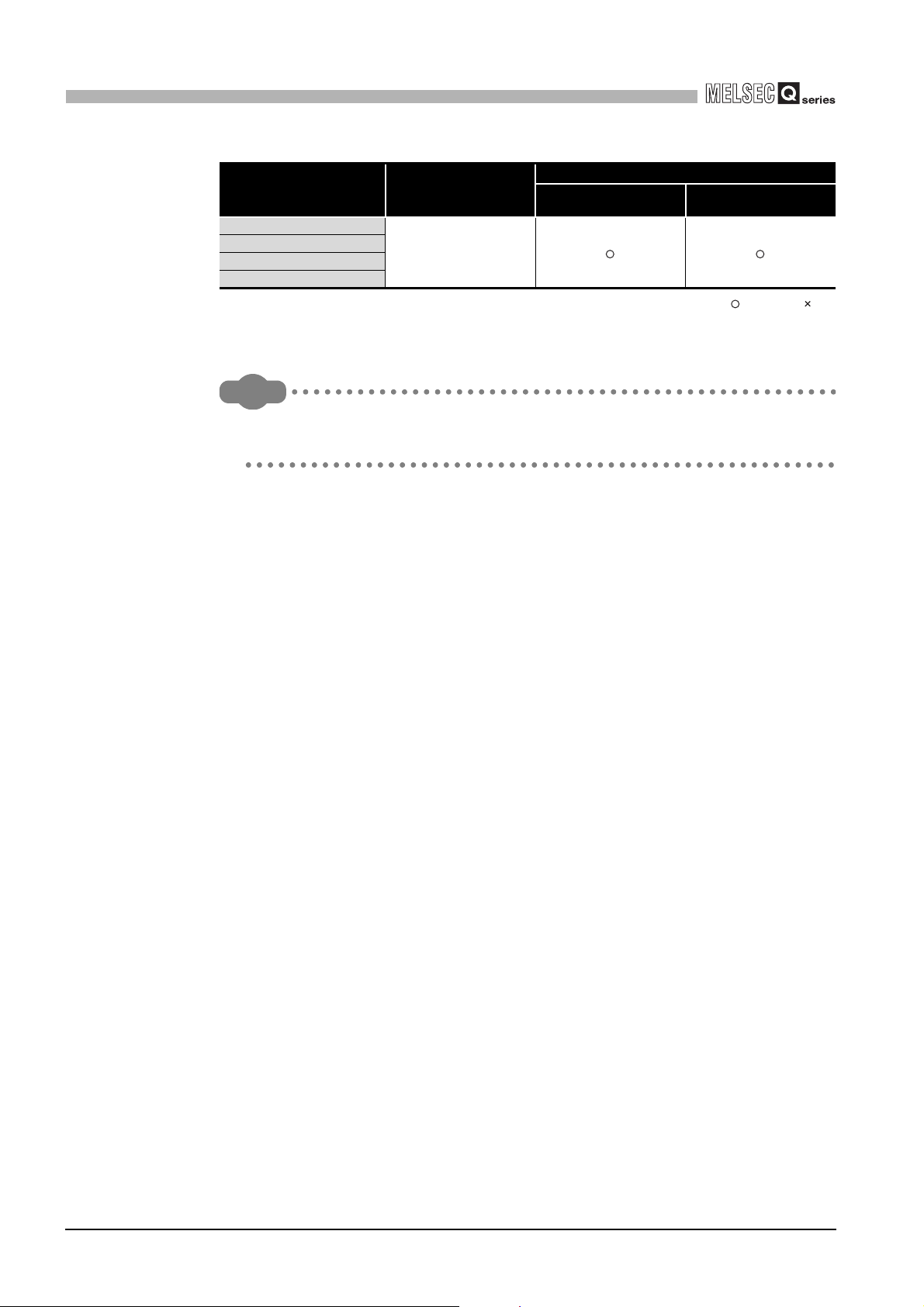
(b) Mounting to a MELSECNET/H remote I/O station
The table below shows the network modules and base units applicable to the
Q68TD-G-H02 (H01) and quantities for each network module model.
Depending on the combination with other modules or the number of mounted
modules, power supply capacity may be insufficient.
Pay attention to the power supply capacity before mounting modules, and if the
power supply capacity is insufficient, change the combination of the modules.
2.1 Applicable Systems
2 - 2
ONLINE MODULE
CHANGE
8
TROUBLESHOOTING
Page 22
2
SYSTEM CONFIGURATION
Table 2.2 Applicable modules, number of mountable modules, and applicable base units
Applicable network module
QJ72LP25-25
QJ72LP25G
QJ72LP25GE
QJ72BR15
* 1 Limited within the range of I/O points for the network module.
* 2 Restrictions apply to mountable slot position. (Refer to (2) in this section)
Remark
The Basic model QCPU or C Controller module cannot create the MELSECNET/
H remote I/O network.
(2) Restrictions on mountable slot position
Number of modules
Up to 64
*1
Main base unit of remote I/O
station
Base unit
*2
Extension base unit of
remote I/O station
:Applicable, :N/A
(a) Restrictions in using both the Q68TD-G-H02 and Q68TD-G-H01
When mounting the Q68TD-G-H02 and Q68TD-G-H01 on the same base unit,
provide one or more than one slot of space between the Q68TD-G-H02 and
Q68TD-G-H01.
2 - 3
2.1 Applicable Systems
Page 23
2
SYSTEM CONFIGURATION
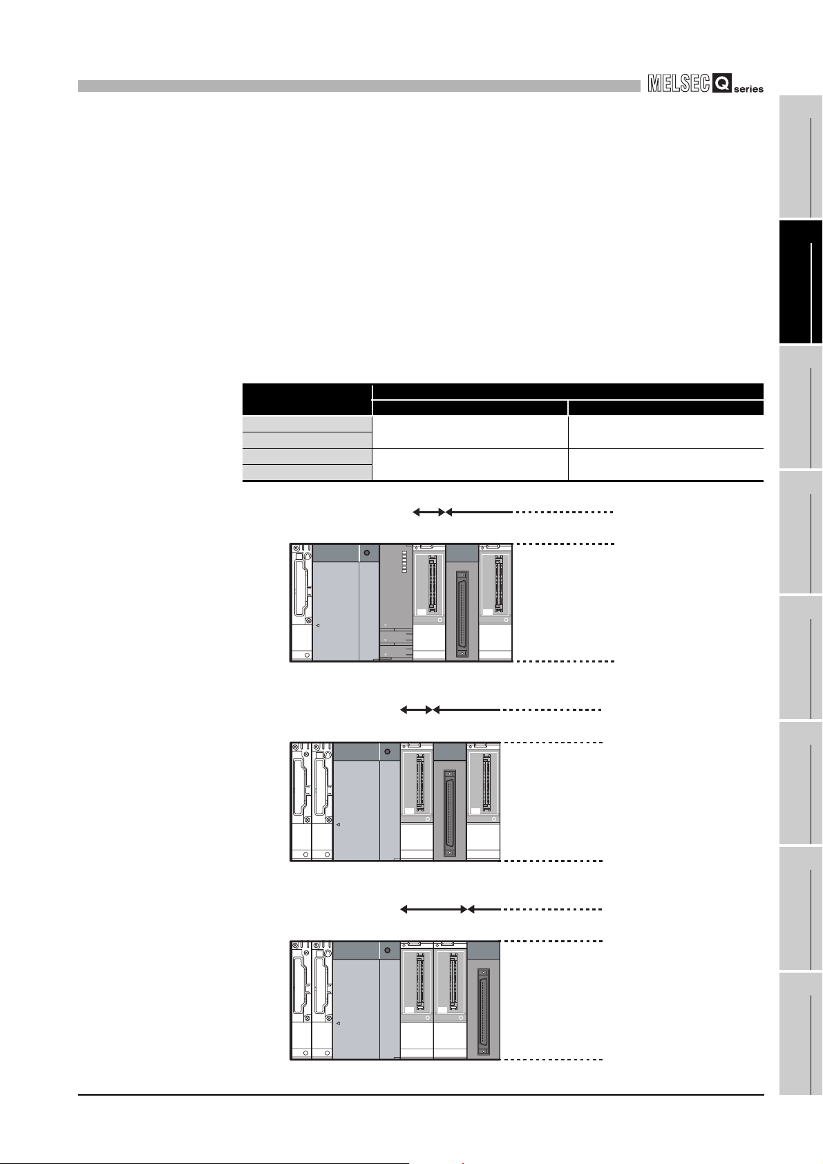
(b) Restriction on mountable slot position of the Q68TD-G-H01
The Q68TD-G-H01 has restrictions on mountable slot position.
The following describes the restrictions of the slot position when mounting the
Q68TD-G-H01 with a combination of the power supply module and the base unit.
For the slot that the Q68TD-G-H01 cannot be mounted, leave the slot open or
mount a module other than the Q68TD-G-H01.
The combination use of modules other than the following power supply modules
and the base units does not have restrictions.
When using the Q68TD-G-H01 on the remote I/O station, the restriction is the
same as for the main base unit.
When failing to comply with the following restrictions, the accuracy might not be in
the specification range.
Table 2.3 Restriction on mountable slot position
Power supply module
Q63P
Q63RP
Q64P Mount the module to I/O slot No.1 or
Q64RP
1)
No restrictions
later. 1)
Restrictions
Main base unit Extension base unit
Mount the module to I/O slot No.1 or
later. 2)
Mount the module to I/O slot No.2 or
later. 3)
Not mountable
Mountable
1
2
3
4
OVERVIEW
SYSTEM
CONFIGURATION
SPECIFICATIONS
Power
supply
OUT
Figure 2.1 Mountable slot position of Q68TD-G-H01
2)
Power
supply
OUT
IN
Figure 2.2 Mountable slot position of Q68TD-G-H01
3)
Power
supply
OUT
IN
Slot
CPU
No.0
I/01 I/01
Not mountable
Slot
Slot
No.0
No.1
I/01 I/01
Not mountable Mountable
Slot
Slot
No.1
No.0
I/01 I/01
Slot
No.1
Mountable
Slot
No.2
Slot
No.2
Slot
No.2
SETUP AND
PROCEDURES BEFORE
OPERATION
5
UTILITY PACKAGE (GX
CONFIGURATOR-TI)
6
PROGRAMMING
7
ONLINE MODULE
CHANGE
8
Figure 2.3 Mountable slot position of Q68TD-G-H01
2.1 Applicable Systems
TROUBLESHOOTING
2 - 4
Page 24
2
SYSTEM CONFIGURATION
(3) Support of the multiple CPU system
The function version of the first released Q68TD-G-H02 (H01) is C, and it supports
multiple CPU systems.
When using the Q68TD-G-H02 (H01) in a multiple CPU system, refer to the following
manual first.
• QCPU User's Manual (Multiple CPU System).
(a) Intelligent function module parameters
Write intelligent function module parameters to only the control CPU of the
Q68TD-G-H02 (H01).
(4) Compatibility with online module change
The Q68TD-G-H02 (H01) is compatible with online module change from the initial
product with function version C.
Refer to CHAPTER 7.
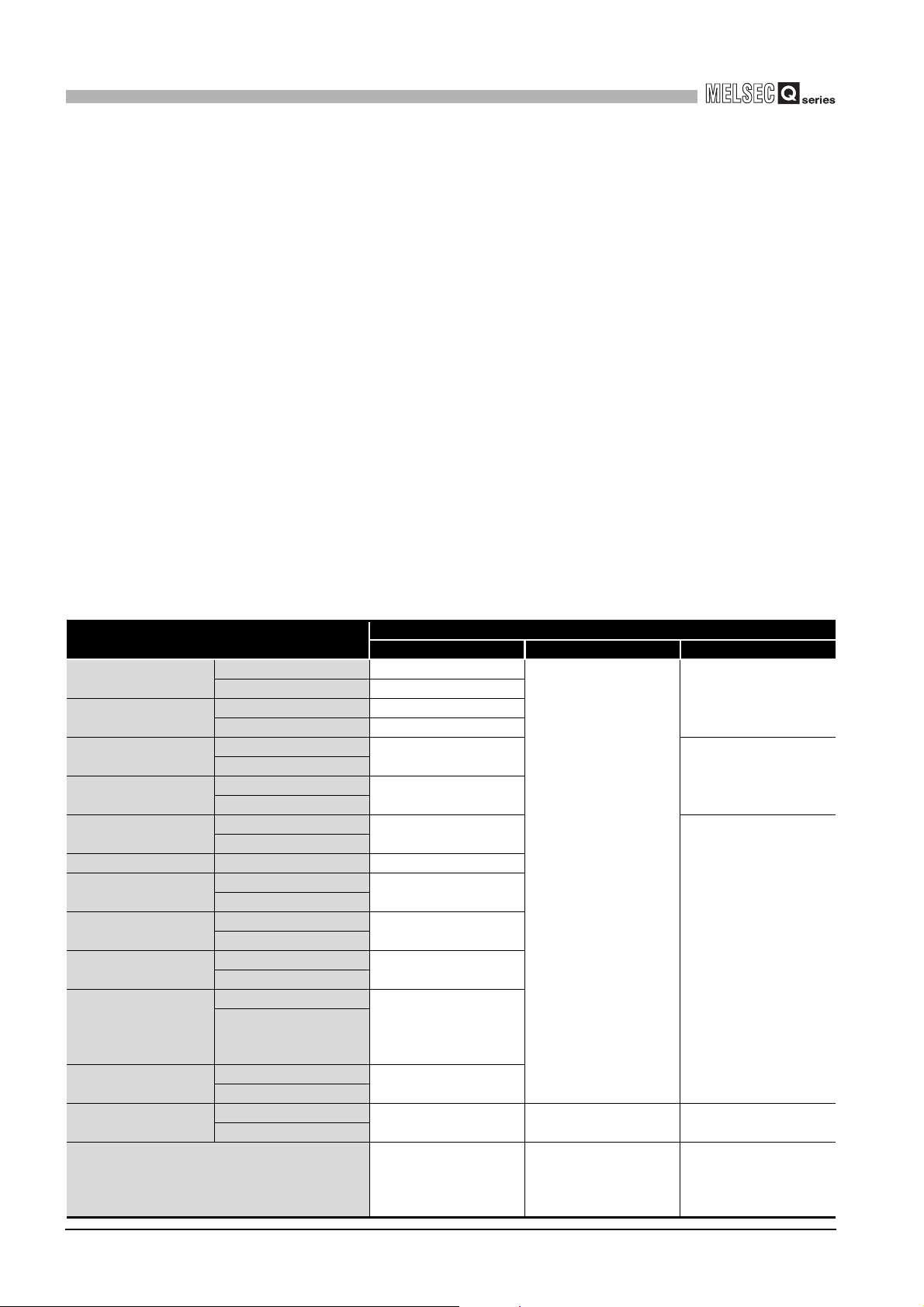
(5) Supported software packages
Relation between the system containing the Q68TD-G-H02 (H01) and software
package is shown in the following table.
GX Developer or GX Works2 is required to use the Q68TD-G-H02 (H01).
Table 2.4 Compatible software and software version
System
Q00J/Q00/Q01CPU
Q02/Q02H/Q06H/ Q12H/
Q25HCPU
Q02PH/Q06PHCPU
Q12PH/Q25PHCPU
Q00UJ/Q00U/Q01UCPU
Q12PRH/Q25PRHCPU Redundant system Version 8.45X or later
Q10UDH/Q20UDHCPU
Q02U/Q03UD/Q04UDH/
Q06UDHCPU
Q13UDH/
Q26UDHCPU
Q03UDE/Q04UDEH/
Q06UDEH/
Q13UDEH/
Q26UDEHCPU
Q10UDEH/
Q20UDEHCPU
Q50UDEH/
Q100UDEHCPU
If installed in a MELSECNET/H remote I/O station Version 6 or later
Single CPU system Version 7 or later
Multiple CPU system Version 8 or later
Single CPU system Version 4 or later
Multiple CPU system Version 6 or later
Single CPU system
Multiple CPU system
Single CPU system
Multiple CPU system
Single CPU system
Multiple CPU system
Single CPU system
Multiple CPU system
Single CPU system
Multiple CPU system
Single CPU system
Multiple CPU system
Single CPU system
Multiple CPU system
Single CPU system
Multiple CPU system
Single CPU system
Multiple CPU system
GX Developer GX Configurator-TI GX Wroks2
Version 8.68W or later
Version 7.10L or later
Version 8.76E or later
Version 8.76E or later
Version 8.48A or later
Version 8.62Q or later
Version 8.68W or later
Version 8.76E or later
Cannot be used Cannot be used Version 1.25B or later
Software Version
Version 1.28AE or later
(Q68TD-G-H02)
Version 1.24AA or later
(Q68TD-G-H01)
Version 1.28AE or later
(Q68TD-G-H02)
Version 1.24AA or later
(Q68TD-G-H01)
Version 1.15R or later
Cannot be used
Version 1.15R or later
Version 1.40S or later
2 - 5
2.1 Applicable Systems
Page 25
2
SYSTEM CONFIGURATION
2.2 When Using the Q68TD-G-H02 (H01) with Redundant CPU
This section describes the use of the Q68TD-G-H02 (H01) with Redundant CPU.
1
(1) Dedicated instruction
The dedicated instruction cannnot be used.
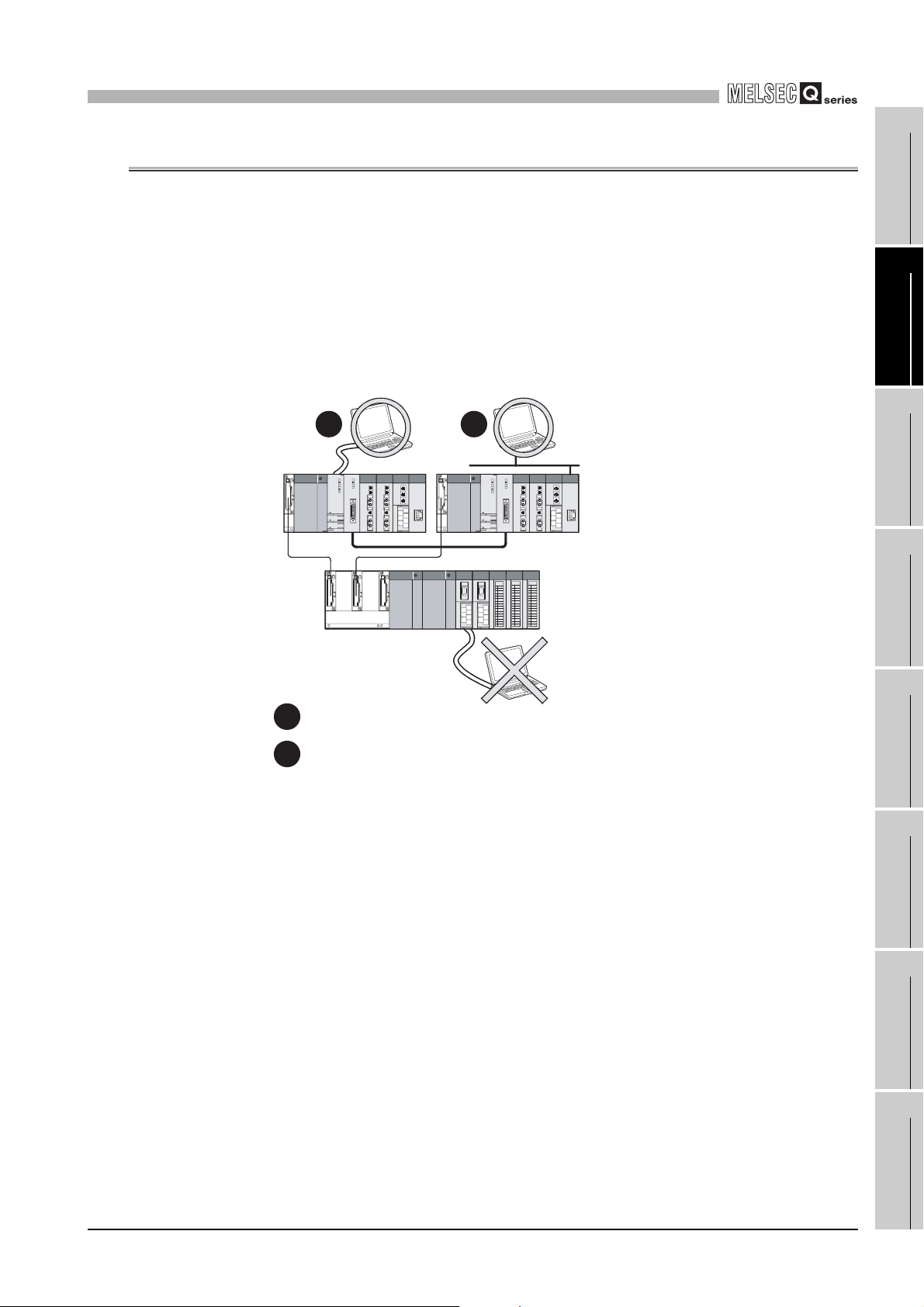
(2) GX Configurator-TI
Configurator-TI cannot be used when accessing Redundant CPU via an intelligent
function module on an extension base unit from GX Developer. Connect a personal
computer with a communication path indicated below.
12
Main base unit
Extension base unit
(GX Configurator-TI cannot be used.)
OVERVIEW
2
SYSTEM
CONFIGURATION
3
SPECIFICATIONS
4
SETUP AND
PROCEDURES BEFORE
OPERATION
5
Direct connection to use the CPU
1
Connection through an intelligent function module on the main base unit
2
(Through Ethernet module, MELSECNET/H module, or CC-Link module)
Figure 2.4 Communication path available for GX Configurator-TI
6
7
8
UTILITY PACKAGE (GX
CONFIGURATOR-TI)
PROGRAMMING
ONLINE MODULE
CHANGE
2.2 When Using the Q68TD-G-H02 (H01) with Redundant CPU
TROUBLESHOOTING
2 - 6
Page 26
2
)
SYSTEM CONFIGURATION
2.3 How to Check the Function Version, Serial No., and Software
Version
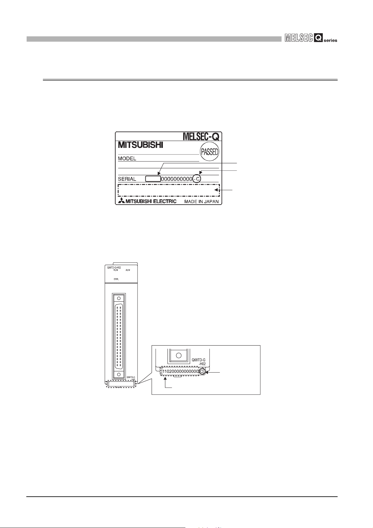
(1) Checking the function version and serial No.
(a) On the rating plate
The rating plate is put on the side of the Q68TD-G-H02 (H01).
(b) On the front of the module
The function version and serial No. on the rating plate is also indicated on the
front of the module (lower part).
11020
Figure 2.5 Rating plate
Serial No. (first 5 digits
Function version
Relevant regulation
standards
2 - 7
Function version
Serial No.
2.3 How to Check the Function Version, Serial No., and Software Version
Page 27
2
SYSTEM CONFIGURATION
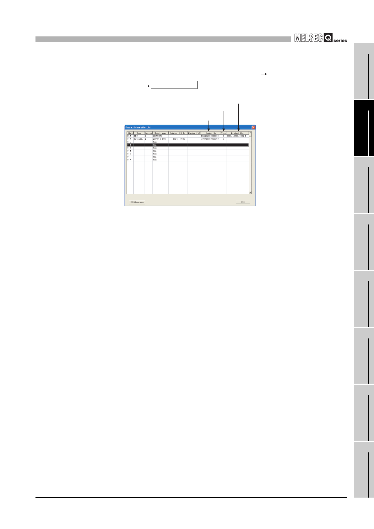
(c) On the system monitor (product information list)
To display the system monitor, select [Diagnostics] [System
monitor] of GX Developer.
Product Inf. List
Function version
Serial No.
Product No.
1
2
3
OVERVIEW
SYSTEM
CONFIGURATION
Figure 2.6 "Product Information List" screen
1) Production number
Production number indication is not available for the Q68TD-G-H02 (H01); "-"
is shown.
SPECIFICATIONS
4
SETUP AND
PROCEDURES BEFORE
OPERATION
5
UTILITY PACKAGE (GX
CONFIGURATOR-TI)
6
PROGRAMMING
7
2.3 How to Check the Function Version, Serial No., and Software Version
2 - 8
ONLINE MODULE
CHANGE
8
TROUBLESHOOTING
Page 28
2
SYSTEM CONFIGURATION
POINT
The serial No. on the rating plate and the front of the module may be different from
the serial No. displayed on the product information list in GX Developer.
• The serial No. on the rating plate and the front of the module indicates the
management information of the product.
• The serial No. displayed on the product information list in GX Developer
indicates the function information of the product. The function information
of the product is updated when a new function is added.
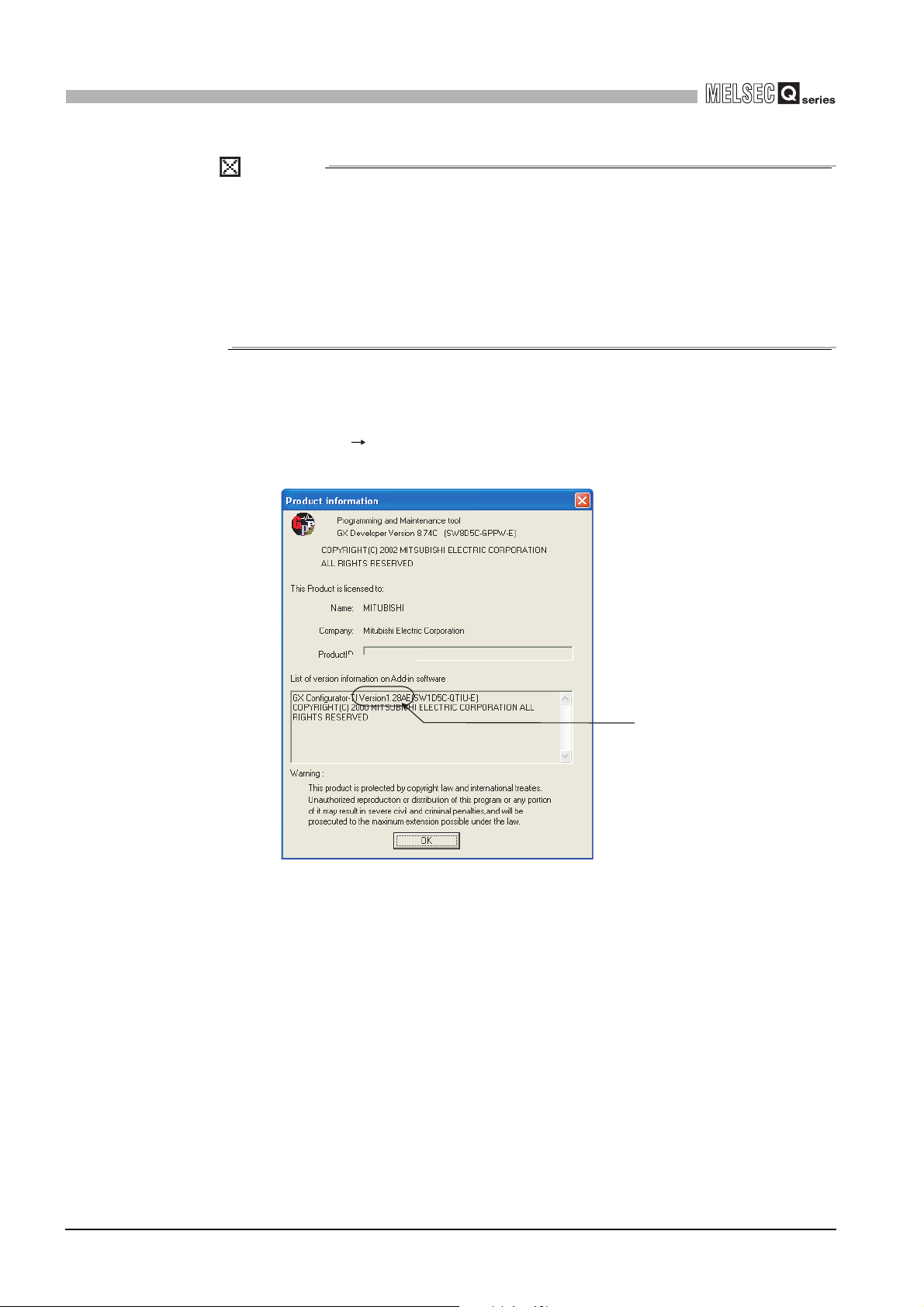
(2) Checking the software version of GX Configurator- TI
The software version of GX Configurator-TI can be checked on GX Developer by
clicking [Help] [Product information].
("Product information" screen of GX Developer Version 8)
Figure 2.7 How to check the software version of GX Configurator- TI
Software version
2 - 9
2.3 How to Check the Function Version, Serial No., and Software Version
Page 29
3
SPECIFICATIONS
CHAPTER3 SPECIFICATIONS
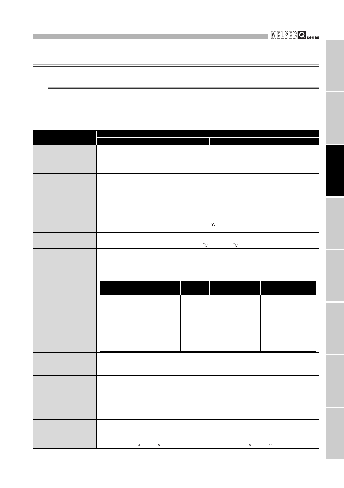
3.1 Performance Specifications
The following are the performance specifications of the Q68TD-G-H02 (H01).
(1) List of performance specifications
Table 3.1 List of performance specifications
Item
Number of channels 8 channels
Temperature
Output
Thermocouple compliance
standards
Applicable thermocouples,
conversion accuracy
effect from wiring resistance
of 1Ω
Cold junction compensation
accuracy
Accuracy
Resolution
Conversion speed
Sampling period
Number of analog input
points
Isolation specifications
Disconnection detection
Maximum number of writes to
flash memory
Number of I/O points
occupied
External connection system 40-pin connector
Applicable wire size
External device connector
(sold separately)
Internal current consumption
(5VDC)
Weight 0.22kg 0.18kg
External dimensions
conversion value
Scaling value 16-bit signed binary
*1
, and
*1
*1
*3
*4
Specific isolated area
Between thermocouple input channel
and programmable controller power
Between thermocouple input
Between cold junction compensation
channel and programmable controller
Available (each channel respectively)
Q68TD-G-H02 Q68TD-G-H01
16-bit signed binary (-2700 to 18200)
JIS C1602-1995,IEC 60584-1(1995),IEC60584-2(1982)
640ms/8 channels 320ms/8 channels
8 channels + cold junction compensation channels/ 1 module
supply
channels
power supply
16 points (I/O assignment: Intelligent 16 points)
2
0.3mm
(AWG22) or less (for A6CON1, A6CON4), 0.24mm2(AWG24) (for A6CON2)
0.65A 0.49A
102(H) 27.4(W) 130(D)mm 98(H) 27.4(W) 90(D)mm
Specifications
Refer to (2) in this section
1.0
Caluculated with formula
B,R,S,N: 0.3 K,E,J,T: 0.1
320ms/8 channels
Isolation
method
Transfer
isolation
Trasnfer
isolation
No isolation - -
*5
A6CON1, A6CON2, A6CON4
Dielectric withstand
500VACrms for 1min
1000VACrms for 1min
50,000
*2
voltage
Not available
Isolation resistance
500VDC 10MΩ or more
*6
1
OVERVIEW
2
SYSTEM
CONFIGURATION
3
SPECIFICATIONS
4
SETUP AND
PROCEDURES BEFORE
OPERATION
5
UTILITY PACKAGE (GX
CONFIGURATOR-TI)
6
PROGRAMMING
7
ONLINE MODULE
CHANGE
8
3.1 Performance Specifications
TROUBLESHOOTING
3 - 1
Page 30

3
SPECIFICATIONS
* 1 To satisfy with the accuracy, a warm-up (power distribution) period of 30 minutes is required.
* 2 Calculate the accuracy in the following method.
(Accuracy) = (conversion accuracy) + (temperature characteristic) (operating ambient
temperature variation) + (cold junction temperature compensation accuracy)
An operating ambient temperature variation indicates a deviation of the operating ambient
temperature from the 25 5 range.
Example: When using the thermocouple B (refer to Section 3.1 (2)) with the operating ambient
temperature of 35 and the measured temperature of 1000 , the accuracy is as follows.
( 2.5 )+( 0.4 )(35-30 )+( 1 )= 5.5
* 3 The conversion speed indicates the maximum time from when the input temperature changes till
when the measured temperature value of buffer memory is batch-updated.
* 4 The sampling period indicates the period batch-updating the measured temperature value in one
channel.
* 5 When disconnection state is detected, output values are selected from "Up scale", "Down scale" or
Given scale". (Refer to Section 3.2.2)
* 6 The Q68TD-G-H01 does not have the disconnection detection function. However, the
disconnection monitor function is available to select a measured temperature value on a
disconnection occurrence from either "Up scale", "Down scale", or "Given value". (Refer to Section
3.2.3)
It takes up to 11s to check a disconnection state.
3 - 2
3.1 Performance Specifications
Page 31

3
Usable
Thermo
couple
Typ e
B
R
S
K
E
J
SPECIFICATIONS
(2) Applicable thermocouples, conversion accuracy, and effect from wiring
resistance of 1Ω
The following table lists applicable thermocouples, conversion accuracy, and the
effect from wiring resistance of 1Ω.
Table 3.2 Applicable thermocouples, conversion accuracy, and the effect from wiring resistance of 1Ω
Measured
Temperature
*1
Range
0 to 600
600 to 800
800 to 1700
1700 to 1820
-50 to 0
0 to 300
300 to 1600
1600 to 1760
-50 to 0
0 to 300
300 to 1600
1600 to 1760
-270 to -200
-200 to 0
0 to 1200
1200 to 1370
-270 to -200
-200 to 0
0 to 900
900 to 1000
-210 to -40
-40 to 750
750 to 1200
Conversion Accuracy
(At operating ambient
temperature 25 5 )
------
*2
*2
3.0
2.5 12.5
------
------
*2
*2
2.5 0.4 12.5
2.0 0.3 9.5
------
------
*2
*2
2.5 0.4 12.5
2.0 0.3 9.5
------
------
Larger value of 0.5 and
*2
0.5% of measured
temperature
Larger value of 0.25
*2
and
0.5% of measured
temperature
------
------
Larger value of 0.5 and
*2
0.5% of measured
temperature
Larger value of 0.5 and
*2
0.25% of measured
temperature
------
------
Larger value of 0.5 and
*2
0.25% of measured
temperature
------
*3
*3
*3
*3
*3
*3
*3
*3
*3
*3
*3
*3
Temperature Characteristic
(Per operating ambient
temperature variation of
1 )
*3
------
0.4
*3
------
*3
------
*3
------
*3
------
*3
------
*3
------
Larger value of 0.06 and
0.2% of measured
temperature
Larger value of 0.06 and
0.02% of measured
temperature
*3
------
*3
------
Larger value of 0.06 and
0.15% of measured
temperature
Larger value of 0.06 and
0.02% of measured
temperature
*3
------
*3
------
Larger value of 0.06 and
0.02% of measured
temperature
*3
------
Max. Temperature
Error at Ambient
Temperature 55
*3
------
13.0
*3
------
*3
------
*3
------
*3
------
*3
------
*3
------
11. 0
9.0
*3
------
*3
------
8.5
6.75
*3
------
*3
------
5.625
*3
------
Effect from wiring
resistance of 1
*4
Ω
(upper: Q68TD-G-H02
lower: Q68TD-G-H01)
*3
------
-0.169 /Ω
-0.042 /Ω
-0.143 /Ω
-0.036 /Ω
*3
------
*3
------
-0.200 /Ω
-0.050 /Ω
-0.112 /Ω
-0.028 /Ω
*3
------
*3
------
-0.200 /Ω
-0.050 /Ω
-0.112 /Ω
-0.028 /Ω
*3
------
*3
------
-0.034 /Ω
-0.009 /Ω
-0.026 /Ω
-0.007 /Ω
*3
------
*3
------
-0.023 /Ω
-0.006 /Ω
-0.018 /Ω
-0.005 /Ω
*3
------
*3
------
-0.022 /Ω
-0.006 /Ω
*3
------
1
OVERVIEW
2
SYSTEM
CONFIGURATION
3
SPECIFICATIONS
4
SETUP AND
PROCEDURES BEFORE
OPERATION
5
UTILITY PACKAGE (GX
CONFIGURATOR-TI)
6
PROGRAMMING
7
ONLINE MODULE
CHANGE
8
3.1 Performance Specifications
TROUBLESHOOTING
3 - 3
Page 32

3
T
N
SPECIFICATIONS
Table 3.2 Applicable thermocouples, conversion accuracy, and the effect from wiring resistance of 1Ω
-270 to -200
-200 to 0
0 to 350
350 to 400
-270 to -200
-200 to 0
0 to 1250
1250 to 1300
------
Larger value of 0.5 and
*2
*2
*2
*2
0.5% of measured
temperature
Larger value of 0.5 and
0.25% of measured
temperature
------
------
Larger value of 0.5 and
0.5% of measured
temperature
Larger value of 0.5 and
0.25% of measured
temperature
------
* 1 If a value entered from the thermocouple is outside the measured temperature range given in the
table, it is handled as the maximum/minimum value of the measured temperature range.
* 2 The accuracies only in the temperature ranges of Class 1 to 3 (shaded areas) in JIS C1602-1995
apply.
Also, a warm-up (power distribution) period of 30 minutes is required to satisfy with the accuracy.
* 3 Temperature measurement can be executed, but accuracy is not guaranteed.
* 4 This is the temperature error per 1Ω wiring resistance of the thermocouple. The temperature error
can be corrected by the offset/gain setting. (Refer to Section 4.6.)
*3
Larger value of 0.06 and
0.1% of measured
Larger value of 0.06 and
0.02% of measured
*3
*3
Larger value of 0.06 and
0.2% of measured
Larger value of 0.06 and
0.02% of measured
*3
*3
------
temperature
temperature
*3
------
*3
------
temperature
temperature
*3
------
------
6.0
2.625
------
------
11. 0
9.375
------
*3
*3
*3
*3
*3
------
-0.036 /Ω
-0.009 /Ω
-0.026 /Ω
-0.007 /Ω
*3
------
*3
------
-0.048 /Ω
-0.012 /Ω
-0.039 /Ω
-0.010 /Ω
*3
------
3 - 4
3.1 Performance Specifications
Page 33

3
SPECIFICATIONS
3.2 Function List
The following table lists the Q68TD-G-H02 (H01) functions.
1
Item Description Refer To
Temperature conversion
function
Temperature conversion
system
Conversion enable/disable
function
Thermocouple type
selection function
Disconnection detection
function
(Q68TD-G-H02 only)
Conversion setting for
disconnection detection
function
(Q68TD-G-H02 only)
Disconnection monitor
function
(Q68TD-G-H01 only)
Disconnection state
conversion setting function
(Q68TD-G-H01 only)
Cold junction temperature
compensation with/without
setting function
Cold junction temperature
compensation resistor
disconnection detection
function
Warning output function
Table 3.3 Function list
This function allows temperature data to be imported by connecting a thermocouple.
Temperature data are 16-bit signed binary (-2700 to 18200) and stored into buffer memory.
(1) Sampling processing
A temperature input value is converted one by one on each channel and a measured
temperature value is output after every conversion. Then the value is stored into buffer
memory.
(2) Averaging processing
This processing averages a measured temperature value for each channel and the
averaged value is stored into buffer memory.
Averaging processing contains three methods as described below.
(a) Time average
(b) Count average
(c) Moving average
(3) Primary delay filter
Measured temperature values are smoothed by a preset time constant.
This function specifies whether temperature conversion is enabled or disabled on each
channel.
This function sets the type of thermocouple on each channel. Section 4.5
This function checks the disconnection of the connected thermocouple on each conversion-
enabled channel.
This function is to select a value to be stored in the CH Measured temperature value
(Un\G11 to Un\G18) from "Up scale", "Down scale" or "Given scale" when disconnection is
detected.
This function checks the disconnection of the connected thermocouple on each conversion-
enabled channel.
This function is to select a value to be stored in the CH Measured temperature value
(Un\G11 to Un\G18) from "Up scale", "Down scale" or "Given scale" when disconnection is
detected.
This function determines whether to use cold junction temperature compensation.
Use this function to measure temperature in higher accuracy than the cold junction
temperature compensation accuracy ( 1 ) by the cold junction temperature
compensation resistor (RTD) that is included with the Q68TD-G-H02 (H01).
The cold junction temperature compensation accuracy can be improved by disabling the
cold junction temperature compensation and providing a precision ice bath externally.
This function detects a disconnection of connected cold junction temperature compensation
resistor (RTD).
(1)
Process alarm
A warning is output when the measured temperature value is equal to or more than the
process alarm upper upper limit value, or equal to or less than the process alarm lower
lower limit value.
(2)
Rate alarm
A warning is output when the measured temperature value changes in a rate by which
the measured temperature value reaches the rate alarm upper limit value or more, or
the rate alarm lower limit value or less.
Section 3.4.5
Section 3.2.1
Section 3.4.2
Section 3.4.15
Section 3.2.2
Section 3.4.16
Section 3.2.3
Section 4.7
Section 3.2.5
Section 3.2.4
OVERVIEW
2
SYSTEM
CONFIGURATION
3
SPECIFICATIONS
4
SETUP AND
PROCEDURES BEFORE
OPERATION
5
UTILITY PACKAGE (GX
CONFIGURATOR-TI)
6
PROGRAMMING
7
ONLINE MODULE
CHANGE
8
3.2 Function List
TROUBLESHOOTING
3 - 5
Page 34

3
SPECIFICATIONS
Table 3.3 Function list
Item Description Refer To
Scaling function
Offset/gain setting function This function compensates an error of measured temperature value.
Online module change A module change is made without the system being stopped. CHAPTER 7
This function can convert a measured temperature value into a preset range ratio (%) and
import it into buffer memory.
Section 3.4.17
to
Section 3.4.20
Section 3.4.11
Section 4.6
3 - 6
3.2 Function List
Page 35

3
SPECIFICATIONS
1
3.2.1 Temperature conversion system
(1) Temperature conversion of Q68TD-G-H02(H01)
Input temperature input
from outside to CH1
Measured temperature
value of CH1 in the
Q68TD-G-H01
(a) Sampling period
The Q68TD-G-H02(H01) measures the temperature from CH1 to CH8 every
40ms per channel.
The sampling period indicates the period (320ms) batch-updating the measured
temperature value in one channel in the case of that the sampling processing is
specified with the Averaging processing selection (Un\G24 and Un\G25).
Regardless of the number of conversion-enabled channels, the measured
temperature values are stored in the buffer memory every 320ms.
(b) Conversion speed
The conversion speed indicates the maximum time required before the measured
temperature values are stored into the buffer memory.
The following figure shows the timing of storing the measured temperature values
of Q68TD-G-H02 and Q68TD-G-H01 respectively.
Trend of CH1 input
temperature (A)
Sampling period
(320ms)
1) 2)
CH1 CH1 CH1 CH1CH2 CH8
The measured temperature
value of 1) is stored
Sampling period
(320ms)
The measured temperature
value of 2) is stored
Maximum
320ms
Sampling period
(320ms)
3) 4)
The measured temperature
value of 3) is stored
Sampling period
(320ms)
The measured temperature
value of 4) is stored
At this point, the CH1
measured temperature
value of the buffer memory,
which is measured with
the trend of (A), is stored.
OVERVIEW
2
SYSTEM
CONFIGURATION
3
SPECIFICATIONS
4
SETUP AND
PROCEDURES BEFORE
OPERATION
5
UTILITY PACKAGE (GX
CONFIGURATOR-TI)
6
Measured temperature
value of CH1 in the
Q68TD-G-H02
At this point, the CH1
measured temperature
value of the buffer memory,
CH1 CH1 CH1 CH1CH2 CH8
Figure 3.1 Q68TD-G-H01 and Q68TD-G-H02 conversion speed overview
The measured temperature
value of 1) is stored
The measured temperature
value of 2) is stored
Maximum
640ms
The measured temperature
value of 3) is stored
which is measured with
the trend of (A), is stored.
(2) Sampling processing
Measured temperature value that is measured at every 320ms of sampling period is
stored in the buffer memory.
3.2 Function List
3.2.1 Temperature conversion system
3 - 7
PROGRAMMING
7
ONLINE MODULE
CHANGE
8
TROUBLESHOOTING
Page 36

3
SPECIFICATIONS
(3) Averaging processing
Averaging processing requires at least 2 times of conversion processing excluding the
maximum and the minimum values.
After the first averaging processing is completed, the corresponding bit for a channel
where processing has been completed of the Conversion completion flag (Un\G10)
turns ON (changes to "1").
(a) Time average
Conversion is executed for a period of set time, and the total value, which
excludes the maximum and the minimum values, is averaged and stored in the
buffer memory.
The number of processing times within the set time is below.
Number of processing times (times) = set time sampling period (320ms)
Setting range of time average is 1280 to 5000ms.
If a value outside the setting range is set, an error (error code: 20 ) occurs.
[Example]
When six channels, channels 1, 2, 3, 4, 5, 6, are enabled for conversion and the
set time is 2000ms, measurement is executed for six times and the average value
is output.
2000 320 =6.25 (times)...... Drop the fractional part
(b) Count average
Conversion is executed for a preset number of times, and the total value
excluding the maximum and the minimum values is averaged and stored in the
buffer memory.
The processing time is below.
Processing time = set count
Setting range of count average is 4 to 500 times.
If a value outside the setting range is set, an error (error code: 30 ) occurs.
[Example]
When six channels, channels 1, 2, 3, 4, 5, 6, are enabled for conversion and the
count averaging is set to 5 times, the average value is output for every 1600(ms).
5
320 = 1600 (ms)
320(ms)
3 - 8
3.2 Function List
3.2.1 Temperature conversion system
Page 37

3
SPECIFICATIONS
(c) Moving average
Measured temperature values, which are taken at every sampling period for the
specified number of times, are averaged and stored in the buffer memory.
The latest measured temperature value can be obtained because the averaging
processing is executed moving for each sampling period.
Measured
temperature value
10000
8000
1
OVERVIEW
2
Sampling period (320ms)
3)
2)
1)
4)
5)
6)
7)
9)
8)
10)
12)
11)
SYSTEM
CONFIGURATION
3
1st storage
2nd storage
3rd storage
CH[] measured temperature value
(Un\G11 to Un\G18)
Conversion completion flag
(Un\G10)
Figure 3.2 Moving average processing for four times settings
Data transition in buffer memory
1st storage
1) + 2) + 3) + 4) 2) + 3) + 4) + 5) 3) + 4) + 5) + 6)
444
Figure 3.3 Buffer memory data change in average processsing
0
0
(a) (b) (c)
Time [ms]
SPECIFICATIONS
4
OFF(0)
2nd storage
ON(1)
3rd storage
SETUP AND
PROCEDURES BEFORE
OPERATION
5
UTILITY PACKAGE (GX
CONFIGURATOR-TI)
6
PROGRAMMING
7
3.2 Function List
3.2.1 Temperature conversion system
3 - 9
ONLINE MODULE
CHANGE
8
TROUBLESHOOTING
Page 38

3
)
SPECIFICATIONS
(4) Primary delay filter
By a preset time constant, measured temperature value of which excessive noise is
smoothed is output.
Depending on the time constant, the degree of smoothness changes.
Time constant is the time until the measured temperature value reaches to 63.2% of
the steady-state value.
The relational expression between the time constant and measured temperature
value is shown below.
[When n=1
Y
[When n=2]
Yn = yn-1 +
[When n 3]
Yn = Yn-1 +
Y
Y
n: Number of sampling times
TA: Time constant (320 to
*1: Conversion completion flag turns ON(1) when n 2.
Setting range of time constant is 320 to 5000ms.
Set the time constant value which is twice as much as the sampling period (320ms).
If the time constant value is not twice as much as the sampling period (320ms), the
value in which the remainder is rounded down is set.
If a value outside the setting range is set, an error (error code: 32 ) occurs.
*1
]
n = 0
t
t
(yn - yn-
(yn - Yn-
t + TA
t + TA
n: Current measured
temperature
n-1: Preceding measured
temperature value
5000ms)
1)
1
yn: Measured temperature value before
smoothing
yn-1: Preceding measured temperature
value before smoothing
Conversion time (320ms)
t:
3 - 10
3.2 Function List
3.2.1 Temperature conversion system
Page 39

3
SPECIFICATIONS
[Example 1: Measured temperature value when the temperature input value is changed
from 250.0
When the time constant setting is 3200ms (3.2s), the measured temperature value
changes as indicated below.
At 3200ms (3.2s) after the temperature input value is changed to 260.0 , the
measured temperature value reaches 63.2% (256.3 )of the value when sampling
processing is selected.
to 260.0 ]
1
OVERVIEW
2
262.0 2620
260.0
258.0
256.0
254.0
252.0
Temperature input value ( )
250.0
Figure 3.4 Measured temperature value when the temperature input value is changed from 250.0 to 260.0
Temperature input value
0 3200
Elapsed time (ms)
Measured temperature value
2600
2580
2560
2540
2520
2500
[Example2: Measured temperature value when the change of temperature input value is a
waveform with ringing]
The changes of measured temperature values when the time constant setting is
1280ms(1.28s), 640ms(0.64s) or the moving average processing is 4 times are shown
below.
Measured temperature value
(Time constant setting 640ms)
Measured temperature value
(Time constant setting 1280ms)
2620
2600
2580
262.0
260.0
258.0
Temperature input value
Measured temperature value
(Moving average processing 4 times)
SYSTEM
CONFIGURATION
3
Measured temperature value
SPECIFICATIONS
4
SETUP AND
PROCEDURES BEFORE
OPERATION
5
UTILITY PACKAGE (GX
CONFIGURATOR-TI)
6
256.0
254.0
252.0
Temperature input value ( )
250.0
0
Figure 3.5 Measured temperature value when the change of temperature input value is a waveform with ringing
1000
2000
3000
4000
Elapsed time (ms)
5000
6000
7000
2560
2540
2520
Measured temperature value
2500
3.2 Function List
3.2.1 Temperature conversion system
3 - 11
PROGRAMMING
7
ONLINE MODULE
CHANGE
8
TROUBLESHOOTING
Page 40

3
SPECIFICATIONS
3.2.2 Conversion setting for disconnection detection function
(Q68TD-G-H02 only)
The conversion setting for disconnection detection function stores specific values into
measured temperature values when disconnection is detected.
This function can identify the disconnection detection from measured temperature values.
This function is only available for channels enable temperature conversion.
(1) Overview of disconnection detection
Maximum 1600msMaximum 640ms
Disconnected
Disconnected(1)
Conversion setting value
for disconnection detection
Normal
Normal(0)
Measured
temperature
value
Disconnection detection signal (XC)
Disconnection detection flag (Un\G49)
CH Measured temperature value
(Un\G11 to Un\G18)
Error clear request (YF)
Figure 3.6 Overview of disconnection detection
Normal
Normal(0)
Measured
temperature
value
(a) It takes up to 640ms till when disconnection is detected.
When disconnection is detected, Disconnection detection flag (Un\G49) and
Disconnection detection signal (XC) turn on. Consequently, “ALM” LED blinks.
(b) When disconnection is detected, the value selected from “Up scale”, “Down scale”
or “Given value” in Conversion setting for disconnection detection
(Un\G164,Un\G165) is stored into CH Measured temperature value (Un\G11 to
Un\G18).
The values specified in Conversion setting for disconnection detection
(Un\G164,Un\G165) remains from when disconnection state is restored till when
normal measured temperature value is stored.
(c) After disconnection state is restored, the batch-update of measured temperature
value restarts automatically.
It takes up to 1600ms from when disconnection state is restored till when
measured temperature value is stored into CH Measured temperature value
(Un\G11 to Un\G18).
3 - 12
(d) The state of Disconnection detection flag (Un\G49), Disconnection detection
signal (XC), and “ALM” LED, which means the state of disconnection detection,
remain even when disconnection state is restored. Turn on Error clear request
(YF).
(e) For operating the warning output function in disconnection and restoration, refer
to Section 3.2.4.
3.2 Function List
3.2.2 Conversion setting for disconnection detection function (Q68TD-G-H02 only)
Page 41

3
SPECIFICATIONS
(2) Setting methods
When “Up scale”, “Down scale” or “Given value” is selected in Conversion setting for
disconnection detection (Un\G164, Un\G165), the value to be stored into CH
Measured temperature value (Un\G11 to Un\G18) in disconnection detection can be
specified.
(a) Up scale and down scale
When “Up scale” (0H) or “Down scale” (1H) is selected, an up scale value or down
scale value of thermocouple-type to be used is stored into the CH Measured
temperature value (Un\G11 to Un\G18).
Thermocouple
type
Thermocouple K 0
Thermocouple E 1
Thermocouple J 2
Thermocouple T 3
Thermocouple B 4
Thermocouple R 5
Thermocouple S 6
Thermocouple N 7
Table 3.4 Upscale and down scale list
Setting value
Measurement
range
-270 to 1370 1452.0 -352.0
-270 to 1000 1063.5 -333.5
-210 to 1200 1270.5 -280.5
-270 to 400 433.5 -303.5
0 to 1820 1911.0 -91.0
-50 to 1760 1850.5 -140.5
-50 to 1760 1850.5 -140.5
-270 to 1300 1378.5 -348.5
Measured temperature value when
disconnection is detected.
Up scale Down scale
1
2
3
4
OVERVIEW
SYSTEM
CONFIGURATION
SPECIFICATIONS
(b) Given value
When “Given value” (2H) is selected, set a value in the CH Conversion setting
value for disconnection detection (Un\G166 to Un\G173) in units of 0.1 .
The value set in the buffer memory above is stored into the CH Measured
temperature value (Un\G11 to Un\G18) when disconnection is detected.
SETUP AND
PROCEDURES BEFORE
OPERATION
5
UTILITY PACKAGE (GX
CONFIGURATOR-TI)
6
PROGRAMMING
7
ONLINE MODULE
CHANGE
8
3.2 Function List
3.2.2 Conversion setting for disconnection detection function (Q68TD-G-H02 only)
TROUBLESHOOTING
3 - 13
Page 42

3
SPECIFICATIONS
3.2.3 Disconnection state conversion setting function (Q68TD-G-H01
only)
This disconnection state conversion setting function stores specific values into measured
temperature values when disconnection is checked.
This function can identify the disconnection detection from measured temperature values.
This function is only available for channels enable temperature conversion.
(1) Overview of disconnection monitor
Maximum 11s Maximum 11s
Disconnected
Normal(0) Normal(0)Disconnected(1)
Measured
temperature value (in
a gradual decline)
Conversion setting for
disconnection state value
Measured
temperature
value
Disconnection state
monitor signal (XC)
Disconnection state monitor
flag (Un\G49)
CH Measured temperature value
(Un\G11 to Un\G18)
Error clear request (YF)
Figure 3.7 Overview of disconnection monitor
Normal Normal
Measured
temperature
value
(a) It takes up to 11s from when line is disconnected till when disconnection is
monitored.
The measured temperature value decreases till when disconnection state is
checked.
When disconnection is checked, Disconnection state monitor flag (Un\G49) and
Disconnection state monitor signal (XC) turn on. Consequently, “ALM” LED blinks.
(b) When disconnection is checked, the value selected from “Up scale”, “Down scale”
or “Given value” in Disconnection state conversion setting (Un\G164,Un\G165) is
stored into the CH Measured temperature value (Un\G11 to Un\G18).
The values specified in Disconnection state conversion setting
(Un\G164,Un\G165) remains from when disconnection state is restored till when
normal measured temperature value is stored.
3 - 14
(c) After disconnection state is restored, the batch-update of measured temperature
value restarts automatically.
It takes up to 11s from when disconnection state is restored till when measured
temperature value is stored into CH Measured temperature value (Un\G11 to
Un\G18).
(d) The state of Disconnection state monitor flag (Un\G49), Disconnection state
signal (XC), and “ALM” LED remains, which means the state of disconnection
detection, remains even when disconnection state is restored. Turn on Error clear
request (YF).
(e) For operating the warning output function in disconnection and restoration, refer
to Section 3.2.4.
3.2 Function List
3.2.3 Disconnection state conversion setting function (Q68TD-G-H01 only)
Page 43

3
SPECIFICATIONS
(2) Setting methods
When “Up scale”, “Down scale” or “Given value” is selected in Disconnection state
conversion setting (Un\G164,Un\G165), the value to be stored into the CH
Measured temperature value (Un\G11 to Un\G18) in disconnection check can be
specified.
(a) Up-scale and down-scale
When “Up scale” (0H) or “Down scale” (1H) is selected, an up-scale value or
down-scale value of thermocouple-type to be used is stored into the CH
Measured temperature value (Un\G11 to Un\G18).
Thermocouple
type
Thermocouple K 0
Thermocouple E 1
Thermocouple J 2
Thermocouple T 3
Thermocouple B 4
Thermocouple R 5
Thermocouple S 6
Thermocouple N 7
Table 3.5 Up-scale and down-scale list
Setting value
Measurement
range
-270 to 1370 1452.0 -352.0
-270 to 1000 1063.5 -333.5
-210 to 1200 1270.5 -280.5
-270 to 400 433.5 -303.5
0 to 1820 1911.0 -91.0
-50 to 1760 1850.5 -140.5
-50 to 1760 1850.5 -140.5
-270 to 1300 1378.5 -348.5
Measured temperature value when
disconnection is detected
Up scale Down scale
1
2
3
4
OVERVIEW
SYSTEM
CONFIGURATION
SPECIFICATIONS
(b) Given value
When “Given value” (2H) is selected, set a value in the CH CH1 Conversion
setting value for disconnection state (Un\G166 to Un\G173) in units of 0.1 .
The value set in the buffer memory above is stored in the CH Measured
temperature value (Un\G11 to Un\G18) during disconnection state.
SETUP AND
PROCEDURES BEFORE
OPERATION
5
UTILITY PACKAGE (GX
CONFIGURATOR-TI)
6
PROGRAMMING
7
ONLINE MODULE
CHANGE
8
3.2 Function List
3.2.3 Disconnection state conversion setting function (Q68TD-G-H01 only)
TROUBLESHOOTING
3 - 15
Page 44

3
SPECIFICATIONS
3.2.4 Warning output function
(1) Process alarm
(a) Warning occurrence
When the detected measured temperature value is higher than or equal to the
process alarm upper upper limit value or lower than or equal to the process alarm
lower lower limit value and falls in the warning output range, a warning occurs.
When a warning occurs, it is notified by storing "1" in the bit position
corresponding to the channel of the warning output flag (process alarm)(Un\G47),
and turning ON the warning output signal (XD) and the [ALM] LED.
(b) Warning clearance
After a warning occurrence, when the temperature value falls lower than the
process alarm upper lower limit value or rises higher than the process alarm lower
upper limit value and returns to within the setting range, the warning is cleared.
When the warning is cleared, "0" is stored in the bit position corresponding to the
channel of the warning output flag (process alarm)(Un\G47).
The warning output signal (XD) turns OFF and the "ALM" LED turns off only when
the process alarm and rate alarm warnings for all channels do not occur or are in
clearance state.
Temperature
Upper upper
limit value
Upper lower
limit value
CH1 measured
temperature value
Lower upper
limit value
CH2 measured
temperature value
Lower lower
limit value
CH1 Process alarm upper
limit value (Un\G47.b0)
CH1 Process alarm lower
limit value (Un\G47.b1)
CH2 Process alarm upper
limit value (Un\G47.b2)
Warning output signal (XD)
Warning
occurence
Warning
occurence
Warning clearance
Warning clearance
Warning output range section
Out of warning output range section
Included
Warning
clearance
Warning
clearance
Time
3 - 16
Figure 3.8 Warning output occurence and clearance (Process alarm)
3.2 Function List
3.2.4 Warning output function
Page 45

3
SPECIFICATIONS
(c) Settable range and default value differ according to the thermocouple type.
Set it in unit of 0.1 .
Thermocouple
type
Thermocouple K -2000 12000 -2700 to 13700 (-2000 to 12000)
Thermocouple E -2000 9000 -2700 to 10000 (-2000 to 9000)
Thermocouple J -400 7500 -2100 to 12000 (-400 to 7500)
Thermocouple T -2000 3500 -2700 to 4000 (-2000 to 3500)
Thermocouple B 6000 17000 0 to 18200 (6000 to 17000)
Thermocouple R 0 16000 -500 to 17600 (0 to 16000)
Thermocouple S 0 16000 -500 to 17600 (0 to 16000)
Thermocouple N -2000 12500 -2700 to 13000 (-2000 to 12500)
(d) When time average or count average is specified, process-alarm processing is
executed for each preset time or count.
When other temperature conversion system (sampling processing, moving
average, or primary delay filter) is specified, process-alarm processing is
executed at every sampling time.
Table 3.6 Settable range and default value of process alarm
Default value
Process
alarm
lower
upper
limit
value
Process
alarm
lower
lower
limit
value
Process
alarm
upper
upper
limit
value
Process
alarm
upper
lower
limit
value
Settable temperature range
(Accuracy guarantee range)
1
2
3
4
OVERVIEW
SYSTEM
CONFIGURATION
SPECIFICATIONS
(e) When the value of the Conversion setting for disconnection detection
(Un\G164,Un\G165) or Disconnection state conversion setting
(Un\G164,Un\G165) is set for disconnection detection or disconnection check as
follows, a warning occur.
• The lower or equal value to the value set in the process alarm lower lower
limit is set.
• The higher or equal value to the value set in the process alarm upper upper
limit is set.
(2) Rate alarm
(a) Warning occurrence
When the measured temperature value is monitored at every rate alarm warning
detection period and the changed portion from the preceding value is larger than
or equal to the rate alarm upper limit value or smaller than or equal to the rate
alarm lower limit value, a warning occurs.
When a warning occurs, it is notified by storing "1" in the bit position
corresponding to the channel of the warning output flag (rate alarm)(Un\G48), and
turning ON the warning output signal (XD) and the [ALM] LED.
SETUP AND
PROCEDURES BEFORE
OPERATION
5
UTILITY PACKAGE (GX
CONFIGURATOR-TI)
6
PROGRAMMING
7
ONLINE MODULE
CHANGE
8
3.2 Function List
3.2.4 Warning output function
TROUBLESHOOTING
3 - 17
Page 46

3
SPECIFICATIONS
(b) Warning clearance
After a warning occurrence, when the changed portion of the measured
temperature value falls lower than the rate alarm upper limit value or rises higher
than the rate alarm lower limit value, and returns to within the setting range, the
warning is cleared.
When the warning is cleared, "0" is stored in the bit position corresponding to the
channel of the warning output flag (rate alarm)(Un\G48).
The warning output signal (XD) turns OFF and the "ALM" LED turns off only when
the process alarm and rate alarm warings for all channels do not occur or are in
clearance state.
Measured
temperature
value
Change of
measured
temperature
value ( C)
Rate alarm
warning
detection
period
Rate alarm
warning
detection
period
Change of CH2
measured
temperature value
Rate alarm
upper limit
value
Rate alarm
lower limit
value
CH1 measured
temperature
value
CH2
measured
temperature
value
Change of
CH1
measured
temperature
value
Time
3 - 18
Time
CH1 Rate alarm upper
limit value (Un\G48.b0)
CH1 Rate alarm lower
limit value (Un\G48.b1)
CH2 Rate alarm upper
limit value (Un\G48.b2)
Warning output signal (XD)
Figure 3.9 Warning output occurence and clearance (Rate alarm)
(c) Set the rate alarm upper limit/lower limit values in units of 0.1 for the measured
temperature range.
Setting range is -32768 to 32767 (-3276.8 to 3276.7 ).
Initial value is set to "0".
3.2 Function List
3.2.4 Warning output function
Page 47

3
SPECIFICATIONS
(d) The rate alarm warning detection period is set based on the period batch-updating
measured temperature values and the number of the periods.
Setting range is 1 to 6000 (times).
Calculation method of the rate alarm warning detection period is below.
(Rate alarm warning detection period) =
(Setting value of the rate alarm warning detection period)
(Temperature measurement value update period)
[Example 1: When setting the rate alarm warning detection period to 150 times with
sampling processing]
Rate alarm warning detection period = 150 times
[Example 2: When setting the rate alarm warning detection period to 150 times with
2000ms of time average for the averaging processing)]
2000
320 = 6.25 (times) Drop the fractional part
The batch-updated period of 2000ms of time average is same as the period of 1920ms
(320ms 6 times)
Rate alarm warning detection period = 150 times
320ms = 48000ms = 48s
1920ms=288000ms = 288s
1
2
3
4
OVERVIEW
SYSTEM
CONFIGURATION
SPECIFICATIONS
[Example 3: When setting the rate alarm warning detection period to 150 times with 10
times of count average for the averaging processing]
Rate alarm warning detection period = 150 times
10 times 320ms = 480000ms =
480s
[Example 4: When setting the rate alarm warning detection period to 150 times with 4
times of moving average for the averaging processing)]
Rate alarm warning detection period = 150 times
320ms=48000ms = 48s
(e) Rate alarm is effective to monitor a change of measured temperature values
within a limited range.
1) Setting example of the rate alarm upper limit/lower limit values for monitoring
that a measured temperature value rises within the specified range
Change of
measured
temperature
value ( C)
20.0
10.0
C
C
0
Rate alarm upper limit value
Rate alarm lower limit value
SETUP AND
PROCEDURES BEFORE
OPERATION
5
UTILITY PACKAGE (GX
CONFIGURATOR-TI)
6
PROGRAMMING
7
Figure 3.10 Setting example of rate alarm upper limit or lower limit
3.2 Function List
3.2.4 Warning output function
Time
3 - 19
ONLINE MODULE
CHANGE
8
TROUBLESHOOTING
Page 48

3
SPECIFICATIONS
2) Setting example of rate alarm upper limit/lower limit values for monitoring that
a measured temperature value drops within the specified range
Change of
measured
temperature
value ( C)
Figure 3.11 Setting example of rate alarm upper limit or lower limit
3) Setting example of rate alarm upper limit/lower limit values for monitoring that
a measured temperature value changes within the specified range
-10.0
-20.0
0
Rate alarm upper limit value
C
C
Rate alarm lower limit value
Time
Change of
measured
temperature
value ( C)
Rate alarm upper limit value
C
10.0
0
C
-10.0
Rate alarm lower limit value
Time
Figure 3.12 Setting example of rate alarm upper limit or lower limit
(f) When the value of the Conversion setting for disconnection detection
(Un\G164,Un\G165) or Disconnection state conversion setting
(Un\G164,Un\G165) is set for disconnection detection or disconnection check as
follows, a warning occur.
• The changed portion from the preceding value is smaller than or equal to the
rate alarm lower limit value.
• The changed portion from the preceding value is larger than or equal to the
rate alarm upper limit value.
3 - 20
(g) After connection is restored, preceding values required for rate alarm occurence
are cleared.
Therefore, a warning does not occur even though the changed portion of
measured temperature values before and after temperature conversion exceeds
the setting range when temperature conversion is restarted.
3.2 Function List
3.2.4 Warning output function
Page 49

3
SPECIFICATIONS
3.2.5 Cold junction temperature compensation resistor disconnection
detection function
This function detects disconnection of cold junction compensation resistor (RTD).
When a cold junction compensation resistor (RTD) connected with a relay terminal block is
disconnected, an error (error code 800) occurs. Consequently, the Error flag (XF) turns on
and the “ERR” LED blinks to notify the error.
(1) Condition for detecting disconnection of cold junction compensation
resistor (RTD)
Disconnection of the cold junction temperature compensation can be detected only
when the switch setting 4 of the intelligent function modules is set to “with cold
junction compensation”.
The following shows the conditions in which the disconnection of the cold junction
temperature compensation resistor (RTD) can be detected.
Table 3.7 Disconnection detection of cold junction temperature compensation resistor
Cold junction temperature
with/without setting
with
without
with ON
Error flag
OFF
RTD
Without disconnection
RTD
Connection state
+
-
GND
+
-
1
OVERVIEW
2
SYSTEM
CONFIGURATION
3
SPECIFICATIONS
4
SETUP AND
PROCEDURES BEFORE
OPERATION
5
GND
With disconnection
+
-
GND
Without connection
without OFF
with ON
without OFF
(2) Operation for detecting disconnection of cold junction compensation
resistor (RTD)
When disconnection of cold junction temperature compensation resistor (RTD) is
detected, conversion for every conversion-enabled channel stops.
The measured temperature value for cold junction temperature compensation resistor
(RTD) disconnection remains the same as the measured value prior to the
disconnection detection.
(3) Operation and processing for restoring disconnection of cold junction
compensation resistor (RTD)
Conversion processing does not restart even after the disconnection of the cold
junction temperature compensation resistor (RTD) is restored.
To restart the conversion processing, turn off the Error clear request (YF).
3.2 Function List
3.2.5 Cold junction temperature compensation resistor disconnection detection function
3 - 21
UTILITY PACKAGE (GX
CONFIGURATOR-TI)
6
PROGRAMMING
7
ONLINE MODULE
CHANGE
8
TROUBLESHOOTING
Page 50

3
SPECIFICATIONS
3.3 I/O Signals Transferred to/from Programmable Controller CPU
This section describes the I/O signal assignment and signal functions.
3.3.1 I/O signal list
The following are the I/O signals of the Q68TD-G-H02 (H01).
The I/O numbers (X/Y) given in this chapter and later assume that the first I/O number of
the Q68TD-G-H02 (H01) is set to 0.
Table 3.8 I/O signal list
Input signal
(Signal direction:
Programmable controller CPU Q68TD-G-H02 (H01))
Device No. Signal name Device No. Signal name
X0 Module ready Y0
X1
X2 Y2
X3 Y3
X4 Y4
X5 Y5
X6 Y6
X7 Y7
X8 Y8
X9 Operating condition setting completion flag Y9 Operating condition setting request
XA Offset/gain setting mode status flag YA User range write request
XB Channel change completion flag YB Channel change request
XC
XD Warning output signal YD
XE Conversion completion flag YE
XF Error flag YF Error clear request
Reserved
Disconnection detection signal (Q68TD-G-H02 only)
Disconnection state monitor signal (Q68TD-G-H01
only)
*1
Programmable controller CPU Q68TD-G-H02 (H01))
Y1
Reserved
YC
Reserved
Output signal
(Signal direction:
*1
*1
3 - 22
POINT
The reserved signals marked *1 are used by the system and are unavailable for
the user. Should they be turned on/off in a sequence program, we cannot
guarantee the functions of the Q68TD-G-H02 (H01).
3.3 I/O Signals Transferred to/from Programmable Controller CPU
3.3.1 I/O signal list
Page 51

3
SPECIFICATIONS
1
3.3.2 I/O signal details
The following are details of the Q68TD-G-H02 (H01) I/O signals.
(1) Module ready (X0)
(a) If the module is in the normal mode at power-on or resetting of the programmable
controller CPU, this signal turns on to start conversion processing as soon as it
gets ready for conversion.
(b) When this signal (X0) is off in the normal mode, conversion processing is not
performed. In the offset/gain setting mode, conversion processing is performed if
this signal (X0) is off.
(c) This signal (X0) turns off when:
• The module is in the offset/gain setting mode
• The Q68TD-G-H02 (H01) is in a watchdog timer error *1
* 1 Occurs if program operation is not completed within the intended time due to errors such as a
hardware fault of the Q68TD-G-H02 (H01). The RUN LED of the Q68TD-G-H02 (H01) goes off
when a watchdog timer error occurs.
(2) Operation condition setting completion flag (X9)
(a) When the following settings are changed, this signal is used as an interlock
condition to turn ON/OFF the operation condition setting request (Y9).
• Conversion enable/disable setting (Un\G0)
• CH Time/Count/Moving average/Time constant setting (Un\G1 to Un\G8)
• Averaging processing selection (Un\G24,Un\G25)
• Warning output enable/disable setting (Un\G46)
• Scaling valid/invalid setting (Un\G58)
• CH Scaling range upper/lower limit value (Un\G62 to Un\G77)
• CH Scaling width upper/lower limit value (Un\G78 to Un\G93)
• CH Process alarm upper/lower limit value (Un\G94 to Un\G125)
• CH Rate alarm warning detection period (Un\126 to Un\G133)
• CH Rate alarm upper/lower limit value (Un\G134 to Un\G149)
• Conversion setting for disconnection detection (Un\G164,Un\G165) (Q68TDG-H02 only)
• Disconnection state conversion setting (Un\G164,Un\G165) (Q68TD-G-H01
only)
• CH Conversion setting value for disconnection detection (Un\G166 to
Un\G173) (Q68TD-G-H02 only)
• CH Conversion setting value for disconnection state (Un\G166 to Un\G173)
(Q68TD-G-H01 only)
When Operation condition setting completion flag (X9) is OFF, conversion processing
is not carried out.
OVERVIEW
2
SYSTEM
CONFIGURATION
3
SPECIFICATIONS
4
SETUP AND
PROCEDURES BEFORE
OPERATION
5
UTILITY PACKAGE (GX
CONFIGURATOR-TI)
6
PROGRAMMING
7
ONLINE MODULE
CHANGE
8
3.3 I/O Signals Transferred to/from Programmable Controller CPU
3.3.2 I/O signal details
TROUBLESHOOTING
3 - 23
Page 52

3
SPECIFICATIONS
(b) Operating condition setting completion flag (X9) turns OFF in the following status.
• When Operating condition setting request (Y9) is ON.
Module ready (X0)
Operating condition
setting completion flag (X9)
Operating condition setting
request (Y9)
Conversion enable/disable
setting (Un\G0)
Conversion completion
flag (XE)
Figure 3.13 When Operating condition setting request (Y9) is ON
(3) Offset/gain setting mode status flag (XA)
(a) In offset/gain setting mode
Executed in Q68TD-G-H02(H01)
Executed in sequence program
Conversion
disabled
Conversion enabled
1) This signal is used as an interlock condition to turn ON/OFF the user range
write request (YA) when the value at completion of offset/gain setting
adjustment is registered.
2) See Section 4.6 regarding the offset/gain settings.
Executed in Q68TD-G-H02(H01)
Module ready (X0)
OFF
Offset/gain setting mode
status flag (XA)
User range write request (YA)
Figure 3.14 Offset/gain setting mode status flag (XA) during offset/gain setting mode
Executed in sequence program
(b) In normal mode
1) This signal is used as an interlock condition to turn ON/OFF the user range
write request (YA) when the user range is restored.
2) Refer to CHAPTER 7 for the user range restoration.
Executed in Q68TD-G-H02(H01)
Module ready (X0)
ON
Executed in sequence program
3 - 24
Offset/gain setting mode status
flag (XA)
User range write request (YA)
Figure 3.15 Offset/gain setting mode status flag (XA) during normal mode
3.3 I/O Signals Transferred to/from Programmable Controller CPU
3.3.2 I/O signal details
Page 53

3
SPECIFICATIONS
(4) Channel change completion flag (XB)
(a) This signal is used as an interlock condition to turn ON/OFF the channel change
request (YB) when changing the channel for the offset/gain setting.
(b) For offset/gain setting, refer to Section 4.6.
Offset/gain setting mode
offset/gain specification
(Un\G26, Un\G27)
Channel change completion
flag (XB)
Channel change request (YB)
Figure 3.16 Channel change completion flag (XB)
Executed in Q68TD-G-H02(H01)
Executed in sequence program
1
2
3
OVERVIEW
SYSTEM
CONFIGURATION
(5) Disconnection detection signal (XC) (Q68TD-G-H02 only)
(a) This signal turns on when any input signal line including a thermocouple in the
input circuit of the conversion-enabled channel is disconnected.
To identify the disconnected channel, check Disconnection detection flag
(Un\G49).
When this signal turns on, conversion update for the conversion-enabled
channels stops.
(b) Measured temperature value when this signal turns on can be selected from "Up
scale", "Down scale", or "Given scale". (Refer to Section 3.2.2)
(c) This signal turns off after eliminating the cause of disconnection and turning on
Error clear request (YF).
(d) When connection is restored, the measured temperature value update is restarted
regardless of the reset of this signal.
(6) Disconnection state monitor signal (XC) (Q68TD-G-H01 only)
(a) The thermocouple input circuit of the conversion-enabled channel turns ON the
disconnection state monitor signal (XC) when any input signal line including the
thermocouple is disconnected.
To identify the disconnected channel, check with the disconnection state monitor
flag (Un\G49).
In addition, conversion update for the conversion-enabled channels stops.
SPECIFICATIONS
4
SETUP AND
PROCEDURES BEFORE
OPERATION
5
UTILITY PACKAGE (GX
CONFIGURATOR-TI)
6
PROGRAMMING
7
(b) For measured temperature values to be stored when the disconnection state
monitor signal (XC) turns ON, any of "Up scale", "Down scale", or "Given value"
can be selected (refer to Section 3.2.3).
(c) Removing the cause of disconnection and turning ON the error clear request (YF)
turns OFF the disconnection state monitor signal (XC).
(d) When the line connection is recovered, the temperature conversion value update
is restarted regardless of the disconnection state monitor signal (XC) reset.
3.3 I/O Signals Transferred to/from Programmable Controller CPU
3.3.2 I/O signal details
3 - 25
ONLINE MODULE
CHANGE
8
TROUBLESHOOTING
Page 54

3
SPECIFICATIONS
(7) Warning output signal (XD)
(a) The warning output signal (XD) turns ON when a process alarm or rate alarm is
detected.
1) Process alarm
• This signal turns ON when the process alarm is enabled and a measured
temperature value exceeds the preset range of the process alarm upper/
lower limit value (Un\G94 to Un\G125) in a conversion-enabled channel.
• For every conversion-enabled channel, the signal automatically turns OFF
when the measured temperature value returns to within the setting range,
and the "ALM" LED also turns off.
2) Rate alarm
• This signal turns ON when the rate alarm is enabled and the change of
measured temperature value exceeds the preset range of the rate alarm
upper/lower limit value (Un\G134 to Un\G149) in a conversion-enabled
channel.
• For every conversion-enabled channel, the signal automatically turns OFF
when the change of measured temperature values return to within the
setting range, and the "ALM" LED also turns off.
Executed in Q68TD-G-H02(H01)
Warning output flag
(Un\G47, Un\G48)
Warning output
signal (XD)
Figure 3.17 On or off for warning output signal (XD)
0
Warning occurrence
(process alarm, rate alarm)
0
3 - 26
3.3 I/O Signals Transferred to/from Programmable Controller CPU
3.3.2 I/O signal details
Page 55

3
SPECIFICATIONS
(8) Conversion completion flag (XE)
(a) Conversion completion flag (XE) turns ON when the measured temperature
values of all conversion-enabled channels are stored into buffer memory after
power-on or hardware reset.
(b) When averaging processing is performed, this signal also turns ON when the
converted measured temperature value is stored into buffer memory after
completion of averaging processing.
(c) When Operating condition setting completion flag (X9) turns on (stop
conversion)
1) After the measured temperature value is stored into buffer memory, the bit of
corresponding channel in Conversion completion flag (Un\G10) turns on
(changes to "1").
2) After the measured temperature values of all conversion-enabled channels are
stored into buffer memory, this flag turns on.
(d) When Operating condition setting completion flag (X9) turns off (conversion
stop)
1
2
3
4
OVERVIEW
SYSTEM
CONFIGURATION
SPECIFICATIONS
1) The bits of all channels in Conversion completion flag (Un\G10) are turned off
(changes to "0").
2) This flag (XE) turns off.
Note that even though conversion has been stopped, the data immediately
before the stop are held in the Measured temperature values stored in the
buffer memory.
(e) Use this signal or Conversion completion flag (Un\G10) as an interlock to read out
the measured temperature value.
(f) This flag (XE) does not turn on when all channels are set to conversion-disabled.
(9) Error Flag (XF)
(a) Error flag (XF) turns ON when a writing error occurs.
(b) To clear the error code, turn ON Error clear request (YF).
Executed in Q68TD-G-H02(H01)
Executed in sequence program
Error code (Un\G19)
Error occurrence
SETUP AND
PROCEDURES BEFORE
OPERATION
5
UTILITY PACKAGE (GX
CONFIGURATOR-TI)
6
PROGRAMMING
7
Error flag (XF)
Error clear request (YF)
Figure 3.18 On or off for Error flag (XF)
3.3 I/O Signals Transferred to/from Programmable Controller CPU
3.3.2 I/O signal details
3 - 27
ONLINE MODULE
CHANGE
8
TROUBLESHOOTING
Page 56

3
SPECIFICATIONS
(10)Operating condition setting request (Y9)
(a) This signal is turned ON when enabling the following setting contents.
• Conversion enable/disable setting (Un\G0)
• CH Time/Count/Moving average/Time constant setting (Un\G1 to Un\G8)
• Averaging processing selection (Un\G24,Un\G25)
• Warning output enable/disable setting (Un\G46)
• Scaling valid/invalid setting (Un\G58)
• CH Scaling range upper/lower limit value (Un\G62 to Un\G77)
• CH Scaling width upper/lower limit value (Un\G78 to Un\G93)
• CH Process alarm upper/lower limit value (Un\G94 to Un\G125)
• CH Rate alarm warning detection period (Un\G126 to Un\G133)
• CH Rate alarm upper/lower limit value (Un\G134 to Un\G149)
• Conversion setting for disconnection detection (Un\G164,Un\G165) (Q68TDG-H02 only)
• Disconnection state conversion setting (Un\G164,Un\G165) (Q68TD-G-H01
only)
• CH Conversion setting value for disconnection detection (Un\G166 to
Un\G173) (Q68TD-G-H02 only)
• CH Conversion setting value for disconnection state (Un\G166 to
Un\G173) (Q68TD-G-H01 only)
(b) When this signal is turned on, Disconnection detection signal (XC) and Warning
output signal (XD) turn off.
(c) For the ON/OFF timing, refer to the field of the operating condition setting
completion flag (X9).
(11)User range write request (YA)
(a) In offset/gain setting mode
1) This signal turns ON when registering the adjusted value of offset/gain setting
to the flash memory.
2) For the ON/OFF timing, refer to the field of the offset/gain setting mode status
flag (XA).
For offset/gain settings, refer to Section 4.6.
(b) In normal mode
1) This signal turns ON when the user range is restored.
2) For the ON/OFF timing, refer to the field of the offset/gain setting mode status
flag (XA).
For user range restoration, refer to CHAPTER 7.
3 - 28
3.3 I/O Signals Transferred to/from Programmable Controller CPU
3.3.2 I/O signal details
Page 57

3
SPECIFICATIONS
(12)Channel change request (YB)
(a) This signal turns ON when changing the channel for executing the offset/gain
setting.
(b) For the ON/OFF timing, refer to the field of the channel change completion flag
(XB).
For the offset/gain setting, refer to Section 4.6.
(13)Error clear request (YF)
(a) This signal turns ON when clearing Error flag (XF) and Disconnection state
monitor signal (XC).
However, the setting value error of the intelligent function module switch setting
cannot be cleared.
Correct the setting value.
(b) For the ON/OFF timing, refer to the filed of Disconnection state monitor signal
(XC) and Error flag (XF)
1
2
3
4
OVERVIEW
SYSTEM
CONFIGURATION
SPECIFICATIONS
SETUP AND
PROCEDURES BEFORE
OPERATION
5
UTILITY PACKAGE (GX
CONFIGURATOR-TI)
6
PROGRAMMING
7
ONLINE MODULE
CHANGE
8
3.3 I/O Signals Transferred to/from Programmable Controller CPU
3.3.2 I/O signal details
TROUBLESHOOTING
3 - 29
Page 58

3
SPECIFICATIONS
3.4 Buffer Memory
3.4.1 Buffer memory assignment
This section describes the assignment of the Q68TD-G-H02 (H01) buffer memory.
POINT
Do not write data from system area or sequence program to the buffer memory area
where writing is disabled.
Doing so may cause malfunction.
Table 3.9 Buffer memory assignment
Addresses
Hex. Dec.
00H 0 Conversion enable/disable setting 00FFH
01H 1 CH1 Time/Count/Moving average/Time constant setting 0
02H 2 CH2 Time/Count/Moving average/Time constant setting 0
03H 3 CH3 Time/Count/Moving average/Time constant setting 0
04H 4 CH4 Time/Count/Moving average/Time constant setting 0
05H 5 CH5 Time/Count/Moving average/Time constant setting 0
06H 6 CH6 Time/Count/Moving average/Time constant setting 0
07H 7 CH7 Time/Count/Moving average/Time constant setting 0
08H 8 CH8 Time/Count/Moving average/Time constant setting 0
09H 9 System area - - -
0AH 10 Conversion completion flag 0 R Section 3.4.4
0BH 11 CH1 Measured temperature value 0 R
0CH 12 CH2 Measured temperature value 0 R
0DH 13 CH3 Measured temperature value 0 R
0EH 14 CH4 Measured temperature value 0 R
0FH 15 CH5 Measured temperature value 0 R
10H 16 CH6 Measured temperature value 0 R
11H 17 CH7 Measured temperature value 0 R
12H 18 CH8 Measured temperature value 0 R
13H 19 Error code 0 R Section 3.4.6
14H 20 Setting range 1(Thermocouple type CH1-CH4) 0 R
15H 21 Setting range 2(Thermocouple type CH5-CH8) 0 R
16H 22 Setting range 3(Offset/gain setting CH1-CH8) 0 R Section 3.4.8
17H 23 System area - - -
18H 24 Averaging processing selection (CH1-CH4) 0
19H 25 Averaging processing selection (CH5-CH8) 0
1AH 26 Offset/gain setting mode(Offset specification) 0
1BH 27 Offset/gain setting mode(Gain specification) 0
Description Default value
Read/Write
*2
R/W
*2
R/W
*2
R/W
*2
R/W
*2
R/W
*2
R/W
*2
R/W
*2
R/W
*2
R/W
*2
R/W
*2
R/W
*2
R/W
*2
R/W
*1
Section 3.4.2
Section 3.4.3
Section 3.4.5
Section 3.4.7
Section 3.4.9
Section 3.4.10
Reference
section
3 - 30
3.4 Buffer Memory
3.4.1 Buffer memory assignment
Page 59

3
SPECIFICATIONS
Table 3.9 Buffer memory assignment
Addresses
Hex. Dec.
1CH 28 CH1 Offset temperature setting value 0
1DH 29 CH1 Gain temperature setting value 0
1EH 30 CH2 Offset temperature setting value 0
1FH 31 CH2 Gain temperature setting value 0
20H 32 CH3 Offset temperature setting value 0
21H 33 CH3 Gain temperature setting value 0
22H 34 CH4 Offset temperature setting value 0
23H 35 CH4 Gain temperature setting value 0
24H 36 CH5 Offset temperature setting value 0
25H 37 CH5 Gain temperature setting value 0
26H 38 CH6 Offset temperature setting value 0
27H 39 CH6 Gain temperature setting value 0
28H 40 CH7 Offset temperature setting value 0
29H 41 CH7 Gain temperature setting value 0
2AH 42 CH8 Offset temperature setting value 0
2BH 43 CH8 Gain temperature setting value 0
2CH 44 System area - - -
2DH 45
2EH 46 Warning output enable/disable setting FFFFH
2FH 47 Warning output flag(Process alarm) 0 R
30H 48 Warning output flag(Rate alarm) 0 R
31H 49
32H 50 CH1 Scaling value 0 R
33H 51 CH2 Scaling value 0 R
34H 52 CH3 Scaling value 0 R
35H 53 CH4 Scaling value 0 R
36H 54 CH5 Scaling value 0 R
37H 55 CH6 Scaling value 0 R
38H 56 CH7 Scaling value 0 R
39H 57 CH8 Scaling value 0 R
3AH 58 Scaling valid/invalid setting 00FFH
3BH 59
to to
3DH 61
Cold junction compensation setting state (Q68TD-G-H02 only) 0 R Section 3.4.12
System area (Q68TD-G-H01 only) - - -
Disconnection detection flag (Q68TD-G-H02 only)
Disconnection state monitor flag (Q68TD-G-H01 only) Section 3.4.16
System area - - -
Description Default value
0R
Read/Write
*2
R/W
*2
R/W
*2
R/W
*2
R/W
*2
R/W
*2
R/W
*2
R/W
*2
R/W
*2
R/W
*2
R/W
*2
R/W
*2
R/W
*2
R/W
*2
R/W
*2
R/W
*2
R/W
*2
R/W
*2
R/W
*1
Section 3.4.11
Section 3.4.13
Section 3.4.14
Section 3.4.15
Section 3.4.17
Section 3.4.18
Reference
section
1
OVERVIEW
2
SYSTEM
CONFIGURATION
3
SPECIFICATIONS
4
SETUP AND
PROCEDURES BEFORE
OPERATION
5
UTILITY PACKAGE (GX
CONFIGURATOR-TI)
6
3.4 Buffer Memory
3.4.1 Buffer memory assignment
3 - 31
PROGRAMMING
7
ONLINE MODULE
CHANGE
8
TROUBLESHOOTING
Page 60

3
SPECIFICATIONS
Table 3.9 Buffer memory assignment
Addresses
Hex. Dec.
3EH 62 CH1 Scaling range lower limit value 0
3FH 63 CH1 Scaling range upper limit value 0
40H 64 CH2 Scaling range lower limit value 0
41H 65 CH2 Scaling range upper limit value 0
42H 66 CH3 Scaling range lower limit value 0
43H 67 CH3 Scaling range upper limit value 0
44H 68 CH4 Scaling range lower limit value 0
45H 69 CH4 Scaling range upper limit value 0
46H 70 CH5 Scaling range lower limit value 0
47H 71 CH5 Scaling range upper limit value 0
48H 72 CH6 Scaling range lower limit value 0
49H 73 CH6 Scaling range upper limit value 0
4AH 74 CH7 Scaling range lower limit value 0
4BH 75 CH7 Scaling range upper limit value 0
4CH 76 CH8 Scaling range lower limit value 0
4DH 77 CH8 Scaling range upper limit value 0
4EH 78 CH1 Scaling width lower limit value 0
4FH 79 CH1 Scaling width upper limit value 0
50H 80 CH2 Scaling width lower limit value 0
51H 81 CH2 Scaling width upper limit value 0
52H 82 CH3 Scaling width lower limit value 0
53H 83 CH3 Scaling width upper limit value 0
54H 84 CH4 Scaling width lower limit value 0
55H 85 CH4 Scaling width upper limit value 0
56H 86 CH5 Scaling width lower limit value 0
57H 87 CH5 Scaling width upper limit value 0
58H 88 CH6 Scaling width lower limit value 0
59H 89 CH6 Scaling width upper limit value 0
5AH 90 CH7 Scaling width lower limit value 0
5BH 91 CH7 Scaling width upper limit value 0
5CH 92 CH8 Scaling width lower limit value 0
5DH 93 CH8 Scaling width upper limit value 0
Description Default value
Read/Write
*2
R/W
*2
R/W
*2
R/W
*2
R/W
*2
R/W
*2
R/W
*2
R/W
*2
R/W
*2
R/W
*2
R/W
*2
R/W
*2
R/W
*2
R/W
*2
R/W
*2
R/W
*2
R/W
*2
R/W
*2
R/W
*2
R/W
*2
R/W
*2
R/W
*2
R/W
*2
R/W
*2
R/W
*2
R/W
*2
R/W
*2
R/W
*2
R/W
*2
R/W
*2
R/W
*2
R/W
*2
R/W
*1
Section 3.4.19
Section 3.4.20
Reference
section
3 - 32
3.4 Buffer Memory
3.4.1 Buffer memory assignment
Page 61

3
SPECIFICATIONS
Table 3.9 Buffer memory assignment
Addresses
Hex. Dec.
5EH 94 CH1 Process alarm lower lower limit value -2000
5FH 95 CH1 Process alarm lower upper limit value -2000
60H 96 CH1 Process alarm upper lower limit value 12000
61H 97 CH1 Process alarm upper upper limit value 12000
62H 98 CH2 Process alarm lower lower limit value -2000
63H 99 CH2 Process alarm lower upper limit value -2000
64H 100 CH2 Process alarm upper lower limit value 12000
65H 101 CH2 Process alarm upper upper limit value 12000
66H 102 CH3 Process alarm lower lower limit value -2000
67H 103 CH3 Process alarm lower upper limit value -2000
68H 104 CH3 Process alarm upper lower limit value 12000
69H 105 CH3 Process alarm upper upper limit value 12000
6AH 106 CH4 Process alarm lower lower limit value -2000
6BH 107 CH4 Process alarm lower upper limit value -2000
6CH 108 CH4 Process alarm upper lower limit value 12000
6DH 109 CH4 Process alarm upper upper limit value 12000
6EH 110 CH5 Process alarm lower lower limit value -2000
6FH 111 CH5 Process alarm lower upper limit value -2000
70H 112 CH5 Process alarm upper lower limit value 12000
71H 113 CH5 Process alarm upper upper limit value 12000
72H 114 CH6 Process alarm lower lower limit value -2000
73H 115 CH6 Process alarm lower upper limit value -2000
74H 116 CH6 Process alarm upper lower limit value 12000
75H 117 CH6 Process alarm upper upper limit value 12000
76H 118 CH7 Process alarm lower lower limit value -2000
77H 119 CH7 Process alarm lower upper limit value -2000
78H 120 CH7 Process alarm upper lower limit value 12000
79H 121 CH7 Process alarm upper upper limit value 12000
7AH 122 CH8 Process alarm lower lower limit value -2000
7BH 123 CH8 Process alarm lower upper limit value -2000
7CH 124 CH8 Process alarm upper lower limit value 12000
7DH 125 CH8 Process alarm upper upper limit value 12000
7EH 126 CH1 Rate alarm warning detection period 0
7FH 127 CH2 Rate alarm warning detection period 0
80H 128 CH3 Rate alarm warning detection period 0
81H 129 CH4 Rate alarm warning detection period 0
82H 130 CH5 Rate alarm warning detection period 0
83H 131 CH6 Rate alarm warning detection period 0
84H 132 CH7 Rate alarm warning detection period 0
85H 133 CH8 Rate alarm warning detection period 0
Description Default value
Read/Write
*2
R/W
*2
R/W
*2
R/W
*2
R/W
*2
R/W
*2
R/W
*2
R/W
*2
R/W
*2
R/W
*2
R/W
*2
R/W
*2
R/W
*2
R/W
*2
R/W
*2
R/W
*2
R/W
*2
R/W
*2
R/W
*2
R/W
*2
R/W
*2
R/W
*2
R/W
*2
R/W
*2
R/W
*2
R/W
*2
R/W
*2
R/W
*2
R/W
*2
R/W
*2
R/W
*2
R/W
*2
R/W
*2
R/W
*2
R/W
*2
R/W
*2
R/W
*2
R/W
*2
R/W
*2
R/W
*2
R/W
*1
Section 3.4.21
Section 3.4.22
Reference
section
1
OVERVIEW
2
SYSTEM
CONFIGURATION
3
SPECIFICATIONS
4
SETUP AND
PROCEDURES BEFORE
OPERATION
5
UTILITY PACKAGE (GX
CONFIGURATOR-TI)
6
PROGRAMMING
7
3.4 Buffer Memory
3.4.1 Buffer memory assignment
3 - 33
ONLINE MODULE
CHANGE
8
TROUBLESHOOTING
Page 62

3
SPECIFICATIONS
Table 3.9 Buffer memory assignment
Addresses
Hex. Dec.
86H 134 CH1 Rate alarm upper limit value 0
87H 135 CH1 Rate alarm lower limit value 0
88H 136 CH2 Rate alarm upper limit value 0
89H 137 CH2 Rate alarm lower limit value 0
8AH 138 CH3 Rate alarm upper limit value 0
8BH 139 CH3 Rate alarm lower limit value 0
8CH 140 CH4 Rate alarm upper limit value 0
8DH 141 CH4 Rate alarm lower limit value 0
8EH 142 CH5 Rate alarm upper limit value 0
8FH 143 CH5 Rate alarm lower limit value 0
90H 144 CH6 Rate alarm upper limit value 0
91H 145 CH6 Rate alarm lower limit value 0
92H 146 CH7 Rate alarm upper limit value 0
93H 147 CH7 Rate alarm lower limit value 0
94H 148 CH8 Rate alarm upper limit value 0
95H 149 CH8 Rate alarm lower limit value 0
96H 150
to to
9DH 157
9EH 158
9FH 159
A0H 160
to to
A3H 163
A4H 164
A5H 165
System area - - -
Mode switching setting 0
System area - - -
Conversion setting for disconnection detection (CH1-
CH4)(Q68TD-G-H02 only)
Disconnection state conversion setting (CH1-CH4)(Q68TD-G-
H01 only)
Conversion setting for disconnection detection (CH5-
CH8)(Q68TD-G-H02 only)
Disconnection state conversion setting (CH5-CH8)(Q68TD-G-
H01 only)
Description Default value
1111
1111
Reference
R/W
R/W
R/W
R/W
R/W
R/W
R/W
R/W
R/W
R/W
R/W
R/W
R/W
R/W
R/W
R/W
R/W
R/W
R/W
*1
*2
*2
*2
*2
*2
*2
*2
*2
*2
*2
*2
*2
*2
*2
*2
*2
*2
*2
*2
section
Section 3.4.23
Section 3.4.24
Section 3.4.25
or
Section 3.4.26
Read/Write
H
H
3 - 34
3.4 Buffer Memory
3.4.1 Buffer memory assignment
Page 63

3
SPECIFICATIONS
Addresses
Hex. Dec.
A6H 166
A7H 167
A8H 168
A9H 169
AAH 170
ABH 171
ACH 172
ADH 173
AEH 174
to to
BDH 189
Table 3.9 Buffer memory assignment
Reference
R/W
R/W
R/W
R/W
R/W
R/W
R/W
R/W
*1
section
*2
*2
*2
*2
Section 3.4.27
Section 3.4.28
*2
*2
*2
*2
Description Default value
CH1 Conversion setting value for disconnection detection
(Q68TD-G-H02 only)
CH1 Conversion setting value for disconnection state (Q68TD-
G-H01 only)
CH2 Conversion setting value for disconnection detection
(Q68TD-G-H02 only)
CH2 Conversion setting value for disconnection state (Q68TD-G-
H01 only)
CH3 Conversion setting value for disconnection detection
(Q68TD-G-H02 only)
CH3 Conversion setting value for disconnection state (Q68TD-G-
H01 only)
CH4 Conversion setting value for disconnection detection
(Q68TD-G-H02 only)
CH4 Conversion setting value for disconnection state (Q68TD-G-
H01 only)
CH5 Conversion setting value for disconnection detection
(Q68TD-G-H02 only)
CH5 Conversion setting value for disconnection state (Q68TD-G-
H01 only)
CH6 Conversion setting value for disconnection detection
(Q68TD-G-H02 only)
CH6 Conversion setting value for disconnection state (Q68TD-G-
H01 only)
CH7 Conversion setting value for disconnection detection
(Q68TD-G-H02 only)
CH7 Conversion setting value for disconnection state (Q68TD-G-
H01 only)
CH8 Conversion setting value for disconnection detection
(Q68TD-G-H02 only)
CH8 Conversion setting value for disconnection state (Q68TD-G-
H01 only)
System area - - -
0
0
0
0
0
0
0
0
Read/Write
or
1
OVERVIEW
2
SYSTEM
CONFIGURATION
3
SPECIFICATIONS
4
SETUP AND
PROCEDURES BEFORE
OPERATION
5
UTILITY PACKAGE (GX
CONFIGURATOR-TI)
6
3.4 Buffer Memory
3.4.1 Buffer memory assignment
3 - 35
PROGRAMMING
7
ONLINE MODULE
CHANGE
8
TROUBLESHOOTING
Page 64

3
SPECIFICATIONS
Addresses
Hex. Dec.
BE
BF
C0
C1
C2
C3
C4
C5
C6
C7
C8
C9
CA
CB
CC
CD
CE
CF
D0
D1
D2
D3
D4
D5
D6
D7
D8
D9
DA
DB
DC
DD
DE
DF
E0
E1
E2
E3
E4
E5
E6
E7
E8
E9
EA
EB
EC
190
H
191
H
192
H
193
H
194
H
195
H
196
H
197
H
198
H
199
H
200
H
201
H
202
H
203
H
204
H
205
H
206
H
207
H
208
H
209
H
210
H
211
H
212
H
213
H
214
H
215
H
216
H
217
H
218
H
219
H
220
H
221
H
222
H
223
H
224
H
225
H
226
H
227
H
228
H
229
H
230
H
231
H
232
H
233
H
234
H
235
H
236
H
Table 3.9 Buffer memory assignment
Description Default value
CH1 Factory default offset value
CH1 Factory default gain value
CH1 User range settings offset value
CH1 User range settings gain value
*3
*3
*3
*3
CH1 User range settings thermal EMF offset value(L)
CH1 User range settings thermal EMF offset value(H)
CH1 User range settings thermal EMF gain value(L)
CH1 User range settings thermal EMF gain value(H)
CH2 Factory default offset value
CH2 Factory default gain value
CH2 User range settings offset value
CH2 User range settings gain value
*3
*3
*3
*3
CH2 User range settings thermal EMF offset value(L)
CH2 User range settings thermal EMF offset value(H)
CH2 User range settings thermal EMF gain value(L)
CH2 User range settings thermal EMF gain value(H)
CH3 Factory default offset value
CH3 Factory default gain value
CH3 User range settings offset value
CH3 User range settings gain value
*3
*3
*3
*3
CH3 User range settings thermal EMF offset value(L)
CH3 User range settings thermal EMF offset value(H)
CH3 User range settings thermal EMF gain value(L)
CH3 User range settings thermal EMF gain value(H)
CH4 Factory default offset value
CH4 Factory default gain value
CH4 User range settings offset value
CH4 User range settings gain value
*3
*3
*3
*3
CH4 User range settings thermal EMF offset value(L)
CH4 User range settings thermal EMF offset value(H)
CH4 User range settings thermal EMF gain value(L)
CH4 User range settings thermal EMF gain value(H)
CH5 Factory default offset value
CH5 Factory default gain value
CH5 User range settings offset value
CH5 User range settings gain value
*3
*3
*3
*3
CH5 User range settings thermal EMF offset value(L)
CH5 User range settings thermal EMF offset value(H)
CH5 User range settings thermal EMF gain value(L)
CH5 User range settings thermal EMF gain value(H)
CH6 Factory default offset value
CH6 Factory default gain value
CH6 User range settings offset value
CH6 User range settings gain value
*3
*3
*3
*3
CH6 User range settings thermal EMF offset value(L)
CH6 User range settings thermal EMF offset value(H)
CH6 User range settings thermal EMF gain value(L)
Reference
R/W
R/W
R/W
R/W
R/W
R/W
R/W
R/W
R/W
R/W
R/W
R/W
R/W
R/W
R/W
R/W
R/W
R/W
R/W
R/W
R/W
R/W
R/W
R/W
R/W
R/W
R/W
R/W
R/W
R/W
R/W
R/W
R/W
R/W
R/W
R/W
*1
section
*2
*2
*2
*2
*2
*2
*2
*2
*2
*2
*2
*2
*2
*2
*2
*2
*2
*2
Section 3.4.29
*2
*2
*2
*2
*2
*2
*2
*2
*2
*2
*2
*2
*2
*2
*2
*2
*2
*2
Read/Write
0
0
0
0
*3
*3
*3
*3
0
0
0
0
0
0
*3
*3
*3
*3
0
0
0
0
0
0
*3
*3
*3
*3
0
0
0
0
0
0
*3
*3
*3
*3
0
0
0
0
0
0
*3
*3
*3
*3
0
0
0
0
0
0
*3
*3
*3
0
0
3 - 36
3.4 Buffer Memory
3.4.1 Buffer memory assignment
Page 65

3
SPECIFICATIONS
Addresses
Hex. Dec.
ED
EE
EF
F0
F1
F2
F3
F4
F5
F6
F7
F8
F9
FA
FB
FC
FD
237
H
238
H
239
H
240
H
241
H
242
H
243
H
244
H
245
H
246
H
247
H
248
H
249
H
250
H
251
H
252
H
253
H
Table 3.9 Buffer memory assignment
Description Default value
CH6 User range settings thermal EMF gain value(H)
CH7 Factory default offset value
CH7 Factory default gain value
CH7 User range settings offset value
CH7 User range settings gain value
*3
*3
*3
*3
CH7 User range settings thermal EMF offset value(L)
CH7 User range settings thermal EMF offset value(H)
CH7 User range settings thermal EMF gain value(L)
CH7 User range settings thermal EMF gain value(H)
CH8 Factory default offset value
CH8 Factory default gain value
CH8 User range settings offset value
CH8 User range settings gain value
*3
*3
*3
*3
CH8 User range settings thermal EMF offset value(L)
CH8 User range settings thermal EMF offset value(H)
CH8 User range settings thermal EMF gain value(L)
CH8 User range settings thermal EMF gain value(H)
* 1 Indicates whether reading from and writing to a sequence program are enabled.
R : Read enabled W : Write enabled
* 2 Data must be written to buffer memory under the interlock conditions (buffer memory write
conditions) of the following I/O signals.
• Operating condition setting
Buffer memory write condition
Y9 X9
Write
request
Operating
condition
setting request
Operating
condition setting
completion flag
Figure 3.19 Setting of interlock conditions
* 3 This area is related with the user range save/restore function and allows users to re-set the offset/
gain values easily in the case of online module change.
1
Reference
R/W
R/W
R/W
R/W
R/W
R/W
R/W
R/W
R/W
R/W
R/W
R/W
R/W
MOV
*1
section
*2
*2
*2
*2
*2
*2
*2
Section 3.4.29
*2
*2
*2
*2
*2
*2
2
3
OVERVIEW
SYSTEM
CONFIGURATION
SPECIFICATIONS
4
SETUP AND
PROCEDURES BEFORE
OPERATION
5
Read/Write
*3
0
0
0
0
0
*3
*3
*3
*3
0
0
0
0
0
0
*3
*3
*3
*3
0
0
3.4 Buffer Memory
3.4.1 Buffer memory assignment
3 - 37
UTILITY PACKAGE (GX
CONFIGURATOR-TI)
6
PROGRAMMING
7
ONLINE MODULE
CHANGE
8
TROUBLESHOOTING
Page 66

3
SPECIFICATIONS
3.4.2 Conversion enable/disable setting (Un\G0)
Temperature conversion enable/disable status is set for each channel.
(1) Setting methods
(a) Set enable/disable status for each channel in buffer memory.
b15 b14 b13 b12 b11 b10 b9 b8 b7 b6 b5 b4 b3 b2 b1 b0
CH8 CH7 CH6 CH5 CH4 CH3 CH2 CH100000000
Data for b8 to b15 are fixed to "0"
Figure 3.20 Setting of enable/disable status (Un\G0)
[Setting example] Setting enable status for channel 1 and 2
b15 b14 b13 b12 b11 b10 b9 b8 b7 b6 b5 b4 b3 b2 b1 b0
1111110000000000
Figure 3.21 Setting example of enable/disable status (Un\G0)
(b) Turn on Operating condition setting request (Y9) to activate the setting.
(2) Default value
The default value is set to “Disable” (00FFH) for all channels.
0: Conversion enabled
1: Conversion disabled
POINT
Setting “Disable” (1) for unused channels can prevent unnecessary disconnection
detection or monitoring disconnection state.
3 - 38
3.4 Buffer Memory
3.4.2 Conversion enable/disable setting (Un\G0)
Page 67

3
SPECIFICATIONS
3.4.3 CH[ ] Time/Count/Moving average/Time constant setting (Un\G1 to
Un\G8)
When the averaging processing (1H to 4H) is specified with Averaging processing
selection (Un\G24, Un\G25), time average, count average, moving average or time
constant for primary delay filter is set. (Refer to Section 3.2.1)
(1) Setting methods
(a) Set the following setting range in buffer memory.
1
OVERVIEW
2
Table 3.10 Settable range
Processing method Setting value
Time average
Count average 4 to 500(times)
Moving average 2 to 60(times)
Primary delay filter
* 1 Set the values in units of 320ms.
For the details of the setting values, refer to Section 3.2.1 (3) Averaging processing or Section
3.2.1 (4) Primary delay filter.
(b) Turn on Operating condition setting request (Y9) to activate the setting. (Refer to
Section 3.3.2)
1280 to 5000(ms)
320 to 5000(ms)
*1
*1
(2) Default value
All channels are set to “0”.
POINT
(1) When a value out of the setting range in Table 3.10 is written, an error occurs
and the following also occurs.
• The error codes (20 , 30 , 31 , 32 ) are stored to the error code
(Un\G19). (Refer to Section 8.1)
• Error flag (XF) turns on.
• Conversion processing is performed with the setting before the error
occurence.
(2) When a value is set on the channels set sampling processing (0
Averaging processing selection (Un\G24, Un\G25), the setting value of CH
Time/Count/Moving average/Time constant setting (Un\G1 to Un\G8) is
ignored.
H) to
SYSTEM
CONFIGURATION
3
SPECIFICATIONS
4
SETUP AND
PROCEDURES BEFORE
OPERATION
5
UTILITY PACKAGE (GX
CONFIGURATOR-TI)
6
PROGRAMMING
7
3.4 Buffer Memory
3.4.3 CH[ ] Time/Count/Moving average/Time constant setting (Un\G1 to Un\G8)
3 - 39
ONLINE MODULE
CHANGE
8
TROUBLESHOOTING
Page 68

3
SPECIFICATIONS
3.4.4 Conversion completion flag (Un\G10)
Conversion state can be checked for each channel.
(1) Data storage
(a) The bit of the corresponding channel in Conversion completion flag turns on
(changes to “1”) when conversion of conversion-enabled channels is completed.
b15 b14 b13 b12 b11 b10 b9 b8 b7 b6 b5 b4 b3 b2 b1 b0
CH8 CH7 CH6 CH5 CH4 CH3 CH2 CH100000000
Data for b8 to b15 are fixed to "0".
Figure 3.22 Storage of Conversion completion flag (Un\G10)
(b) Conversion completion flag (XE) turns on when conversion of all conversion-
enabled channels is completed.
(2) How to clear stored data
When Operating condition setting request (Y)) is turned on, the bit of all channels in
the Conversion completion flag returns to default value (“0”).
0: During conversion or unused
1: Conversion completed
POINT
Use this area or Conversion completion flag (XE) as an interlock to read out the
measured temperature value.
3 - 40
3.4 Buffer Memory
3.4.4 Conversion completion flag (Un\G10)
Page 69

3
SPECIFICATIONS
3.4.5 CH[ ] Measured temperature value (Un\G11 to Un\G18)
“Thermal electromotive force values” input from thermocouples are converted into
“temperature values” to check values of detected temperature.
(1) Data storage
The measured temperature value rounded off to one decimal place is multiplied by 10
and the result is stored into buffer memory in 16-bit signed binary. (Drop the second
decimal place and later.)
1
OVERVIEW
2
[Setting example 1]
When the measured temperature value is 123.025 1230 is stored.
b15 b14 b13 b12 b11 b10 b9 b8 b7 b6 b5 b4 b3 b2 b1 b0
1100111000000100
Figure 3.23 Storage example 1 of CH Measured temperature value (Un\G11 to Un\G18)
When the measured temperature value is -123.0 -1230 is stored.
b15 b14 b13
11111011
Figure 3.24 Storage example 2 of CH Measured temperature value (Un\G11 to Un\G18)
b12b11b10b9b8b7b6b5b4b3b2b1b0
00110010
POINT
(1) When disconnection is detected or checked with a monitor, the values set in
Conversion setting for disconnection detection (Un\G164, Un\G165) or
Disconnection state conversion setting (Un\G164, Un\G165) are stored into
the CH Measured temperature value (Un\G11 to Un\G18). (Refer to Section
3.4.25, Section 3.4.26)
(2) After the disconnection recovery, normal measured temperature value is
automatically stored.
(3) Use Conversion completion flag (XE) or Conversion completion flag (Un\G10)
as an interlock to read out the measured temperature value.
SYSTEM
CONFIGURATION
3
SPECIFICATIONS
4
SETUP AND
PROCEDURES BEFORE
OPERATION
5
UTILITY PACKAGE (GX
CONFIGURATOR-TI)
6
3.4 Buffer Memory
3.4.5 CH[ ] Measured temperature value (Un\G11 to Un\G18)
3 - 41
PROGRAMMING
7
ONLINE MODULE
CHANGE
8
TROUBLESHOOTING
Page 70

3
SPECIFICATIONS
3.4.6 Error code (Un\G19)
Error codes that are detected by the Q68TD-G-H02(H01) are stored. (Refer to Section
8.1)
3.4.7 Setting range 1, 2 (Thermocouple type) (Un\G20,Un\G21)
This area is for checking thermocouple type of the Q68TD-G-H02(H01). which is set with
Switch 1 and 2 in the intelligent function module switch setting. (Refer to Section 4.5)
(1) Data storage
(a) The setting value of thermocouple type is stored into the position shown in the
following figure for each channel.
Un\G20
(Setting range CH1 to CH4)
Un\G21
(Setting range CH5 to CH8)
Figure 3.25 Storage of setting range 1,2 (thermocouple type) (Un\G20,Un\G21)
b15
to
CH4 CH3 CH1
CH8 CH7 CH6 CH5
b12 b11
to
b8 b7
to
CH2
(b) The following table shows the setting value for each thermocouple type.
Table 3.11 Thermocouple and setting value
Themocouple type Setting value
Thermocouple K 0H
Thermocouple E 1H
Thermocouple J 2H
Thermocouple T 3H
Thermocouple B 4H
Thermocouple R 5H
Thermocouple S 6H
Thermocouple N 7H
3.4.8 Setting range 3 (Offset/gain setting) (Un\G22)
b4 b3
to
b0
3 - 42
This area is for checking offset/gain setting of the Q68TD-G-H02(H01). which is set with
Switch 3 in the intelligent function module switch setting. (Refer to Section 4.5)
(1) Data storage
The setting value of offset/gain setting is stored into the position corresponding to the
channels shown in the following figure.
b15 b14 b13 b12 b11 b10 b9 b8 b7 b6 b5 b4 b3 b2 b1 b0
CH8 CH7 CH6 CH5 CH4 CH3 CH2 CH100000000
Data for b8 to b15 are fixed to "0".
Figure 3.26 Storage of setting range 3 (Offset/gain setting) (Un\G22)
3.4 Buffer Memory
3.4.6 Error code (Un\G19)
0: Factory default setting
1: User range setting
Page 71

3
SPECIFICATIONS
1
3.4.9 Averaging processing selection (Un\G24,Un\G25)
Averaging processing is selected for each channel.
(1) Setting methods
(a) The Averaging processing selection is set in the position corresponding to each
channel of buffer memory shown in the following figure.
Un\G24 (Averaging processing
selection CH1 to CH4)
Un\G25 (Averaging processing
selection CH5 to CH8)
Figure 3.27 Setting of Averaging processing selection (Un\G24,Un\G25)
(b) The following table shows the setting value.
Table 3.12 Processing method and setting value
(c) Turn on Operating condition setting request (Y9) to activate the setting.
(2) Default value
All channels are set to sampling processing (0000H).
b15 b12 b11 b8 b7 b4 b3 b0
Processing method Setting value
Samplling processing 0H
Moving average 3H
Primary delay filter 4H
to
CH4 CH3 CH2 CH1
CH8 CH7 CH6 CH5
Time average 1H
Count average 2H
to
to to
OVERVIEW
2
SYSTEM
CONFIGURATION
3
SPECIFICATIONS
4
SETUP AND
PROCEDURES BEFORE
OPERATION
5
[Setting example]
• CH1 Count average (2H)
• CH2 Time average (1
• CH3 Primary delay filter (4
• CH4 Sampling processing (0
Set “0412
setting.
Un\G24 (Averaging processing
selection CH1 to CH4)
Figure 3.28 Setting example of Averaging processing selection (Un\G24,Un\G25)
POINT
H)
H)
H)
H” for Un\G24 as shown in the following figure in the case of the above
b15 b14 b13 b12 b11 b10 b9 b8 b7 b6 b5 b4 b3 b2 b1 b0
0001001000000100
If a value out of the setting range is set, sampling processing is performed.
6
7
8
UTILITY PACKAGE (GX
CONFIGURATOR-TI)
PROGRAMMING
ONLINE MODULE
CHANGE
3.4 Buffer Memory
3.4.9 Averaging processing selection (Un\G24,Un\G25)
TROUBLESHOOTING
3 - 43
Page 72

3
SPECIFICATIONS
3.4.10 Offset/gain setting mode (Un\G26,Un\G27)
A channel targeted for adjusting offset/gain setting values in the offset/gain setting mode is
specified. (Refer to Section 4.6)
(1) Setting methods
Set a channel targeted for adjusting offset setting in Un\G26, and a channel for gain
setting in Un\G27.
b7 b6 b5 b4 b3 b2 b1 b0
Un\G26
(Offset specification)
b15 b14 b13 b12 b11 b10 b9 b8
00000000
CH4 CH3 CH2 CH1CH8 CH7 CH6 CH5
Un\G27
(Gain specification)
Figure 3.29 Setting of Averaging processing selection (Un\G24,Un\G25)
(2) Default value
All channels are set to “Disable” (0000H).
POINT
00000000
Data for b8 to b15 are fixed to "0". 1: Setting channel
Setting multiple channels at the same time is possible, however, set offset and
gain values separately (set “0” in either Un\G26 or Un\G27).
If both are set to the same channel, an error (error code500) occurs.
CH4 CH3 CH2 CH1CH8 CH7 CH6 CH5
0: disable
3 - 44
3.4 Buffer Memory
3.4.10 Offset/gain setting mode (Un\G26,Un\G27)
Page 73

3
SPECIFICATIONS
3.4.11 CH[ ] Offset/gain temperature setting values (Un\G28 to Un\G43)
Measured temperature values equivalent to the input from the sensor are set during the
offset/gain setting mode.
(1) Setting methods
(a) Input a value used as an offset value or gain value in 16-bit signed binary (units of
0.1 ) to the channel set in the Offset/gain setting mode (Un\G26,Un\G27).
(b) When Channel change request (YB) is turned on, measured temperature value is
compensated for the value written in this area.
(2) Default value
All channels are set to “0”.
POINT
(1) High accuracy is ensured for Offset/gain temperature setting values when the
minimum or maximum temperature of the operating range is used to
compensate errors.
(2) Set Offset/gain temperature setting values while reading measured
temperature values.
(3) Satisfy the following conditions when setting the Offset/gain temperature
setting values. If the conditions are not satisfied, an error (error code: 41 )
occurs.
• Condition 1: Within the input enabled range
• Condition 2: (Gain temperature setting value) - (Offset temperature
setting value) > 0.1[ ]
(4) Offset/gain temperature setting values are stored into the flash memory of the
Q68TD-G-H02(H01) turning on User range write request (YA), and the values
are not erased at power-off.
1
OVERVIEW
2
SYSTEM
CONFIGURATION
3
SPECIFICATIONS
4
SETUP AND
PROCEDURES BEFORE
OPERATION
5
UTILITY PACKAGE (GX
CONFIGURATOR-TI)
6
3.4.12 Cold junction compensation setting status (Un\G45) (Q68TD-GH02 only)
The Cold junction compensation setting status of the Q68TD-G-H02, set with Switch 4 in
the intelligent function module, can be checked.
(1) Data storage
Table 3.13 Cold junction compensation setting state (Un\G45)
Cold junction
Storage value
0000H Available
0001H Not available
3.4.11 CH[ ] Offset/gain temperature setting values (Un\G28 to Un\G43)
compensation
setting state
3.4 Buffer Memory
3 - 45
PROGRAMMING
7
ONLINE MODULE
CHANGE
8
TROUBLESHOOTING
Page 74

3
SPECIFICATIONS
3.4.13 Warning output enable/disable setting (Un\G46)
Enable/disable state of warning output for process alarm or rate alarm is set for each
channel.
(1) Setting methods
(a) Warning output enable/disable setting is set for the corresponding channels in the
following figure.
b15 b14 b13 b12 b11 b10 b9 b8 b7 b6 b5 b4 b3 b2 b1 b0
CH4 CH3 CH2 CH1CH8 CH7 CH6 CH5CH4 CH3 CH2 CH1CH8 CH7 CH6 CH5
Rate alaram setting
0: Enable,
Figure 3.30 Setting of Warning output enable/disable setting (Un\G46)
(b) Turn on Operating condition setting request (Y9) to activate the setting.
(2) Default value
Both process alarm and rate alarm are set to “Disable” for all channels (FFFFH).
1: Disable
Process alarm setting
3 - 46
3.4 Buffer Memory
3.4.13 Warning output enable/disable setting (Un\G46)
Page 75

3
SPECIFICATIONS
3.4.14 Warning output flag (Process alarm/Rate alarm) (Un\G47,Un\G48)
For both process alarm and rate alarm, whether the warning is for the upper limit value or
lower limit value can be checked for each channel.
(1) Data storage
(a) When a measured temperature value is out of the setting range of the CH
Process alarm upper/lower limit values (Un\G94 to Un\G125) or CH Rate alarm
upper/lower limit values (Un\G134 to Un\G149), the bit of the corresponding
channels turns on (changes to “1”).
b15 b14 b13 b12 b11 b10 b9 b8 b7 b6 b5 b4 b3 b2 b1 b0
Un\G47 (Process alarm)
CH3 lower
CH8 lower
limit value
b15 b14 b13 b12 b11 b10 b9 b8 b7 b6 b5 b4 b3 b2 b1 b0
CH7 lower
limit value
CH8 upper
limit value
CH6 lower
CH7 upper
limit value
limit value
CH6 upper
limit value
CH5 lower
limit value
CH5 upper
CH4 lower
limit value
limit value
CH4 upper
limit value
limit value
CH3 upper
limit value
CH2 lower
limit value
CH2 upper
CH1 lower
limit value
limit value
0: Normal
1: Alarm ON
CH1 upper
limit value
1
2
3
4
OVERVIEW
SYSTEM
CONFIGURATION
SPECIFICATIONS
Un\G48 (Rate alarm)
Figure 3.31 Storage of Warning output flag (Process alarm/Rate alarm) (Un\G47,Un\G48)
CH8 lower
limit value
CH8 upper
CH7 lower
limit value
limit value
CH7 upper
limit value
limit value
CH6 upper
limit value
CH5 lower
limit value
CH5 upper
CH4 lower
limit value
limit value
CH4 upper
limit value
CH3 upper
CH3 lower
limit value
limit value
CH2 lower
limit value
CH1 lower
limit value
CH2 upper
limit value
0: Normal
1: Alarm ON
CH1 upper
CH6 lower
(b) When the measured temperature value or the change of measured temperature
values returns to within the setting range, this flag will be automatically reset.
(c) When Operating condition setting request (Y9) is turned on, this flag will be
cleared.
(d) If a warning is detected on any of channels for the conditions described below,
Warning output signal (XD) also turns on.
1) Conversion enable (“0”) is set in Conversion enable/disable setting (Un\G0).
2) Process alarm setting or rate alarm setting are set to “Enable”(“0”) in the
Warning output enable/disable (Un\G46).
limit value
SETUP AND
PROCEDURES BEFORE
OPERATION
5
UTILITY PACKAGE (GX
CONFIGURATOR-TI)
6
PROGRAMMING
7
3.4 Buffer Memory
3.4.14 Warning output flag (Process alarm/Rate alarm) (Un\G47,Un\G48)
3 - 47
ONLINE MODULE
CHANGE
8
TROUBLESHOOTING
Page 76

3
SPECIFICATIONS
3.4.15 Disconnection detection flag (Un\G49) (Q68TD-G-H02 only)
Disconnection state is detectable for each channel.
(1) Data storage
(a) The bit of the corresponding channel turns on (changes to “1”) when the
disconnection state of a thermocouple or compensating lead wire is detected.
b15 b14 b13 b12 b11 b10 b9 b8 b7 b6 b5 b4 b3 b2 b1 b0
CH8 CH7 CH6 CH5 CH4 CH3 CH2 CH100000000
Data for b8 to b15 is fixed to "0".
Figure 3.32 Storage of Disconnection detection flag (Un\G49)
(b) Conversion for the channels not disconnected is continued.
(2) How to clear flag
(a) Check the sensor connection state of disconnection detection channels.
(b) When Operating condition setting request (Y9) or Error clear request (YF) is
turned on, this flag will be cleared.
When the signal turns on in disconnection state, the bit of the corresponding
channel turns on (changes to “1”) again.
0: Normal
1: Disconnected
3 - 48
3.4 Buffer Memory
3.4.15 Disconnection detection flag (Un\G49) (Q68TD-G-H02 only)
Page 77

3
SPECIFICATIONS
(3) Relationship between the Disconnection detection flag and conversion
enable/disable setting.
The following table shows the relationship between the Disconnection detection flag
and conversion enable/disable setting.
Table 3.14 Relationship between conversion enable/disable setting and Disconnection detection flag
Connection state
Conversion enable/disable
setting
1
OVERVIEW
2
Disconnection detection
flag
Enable
Disable
Enable ON
Disable OFF
Enable ON
Disable OFF
Without disconnection
With disconnection
Without connection
+
-
+
-
+
-
POINT
(1) Always set “Disable” for any channel where no thermocouple or
compensating lead wire is connected.
If “Enable” is set, the bit of the corresponding channel in the Disconnection
detection flag (Un\G49) turns on (changes to “1”).
(2) For wiring of a thermocouple or compensating lead wire, refer to Section 4.4.
(3) For troubleshooting of disconnection detection, refer to Section 8.2.7.
OFF
SYSTEM
CONFIGURATION
3
SPECIFICATIONS
4
SETUP AND
PROCEDURES BEFORE
OPERATION
5
3.4 Buffer Memory
3.4.15 Disconnection detection flag (Un\G49) (Q68TD-G-H02 only)
3 - 49
UTILITY PACKAGE (GX
CONFIGURATOR-TI)
6
PROGRAMMING
7
ONLINE MODULE
CHANGE
8
TROUBLESHOOTING
Page 78

3
SPECIFICATIONS
3.4.16 Disconnection state monitor flag (Un\G49) (Q68TD-G-H01only)
Disconnection state is detectable for each channel.
(1) Data storage
(a) The bit of the corresponding channel turns on (changes to “1”) when the
disconnection state of a thermocouple or compensating lead wire is checked.
b15 b14 b13 b12 b11 b10 b9 b8 b7 b6 b5 b4 b3 b2 b1 b0
CH8 CH7 CH6 CH5 CH4 CH3 CH2 CH100000000
Data for b8 to b15 is fixed to "0".
Figure 3.33 Storage of Disconnection state monitor flag (Un\G49)
(b) Conversion for the channels not disconnected is continued.
(2) How to clear flag
(a) Check the sensor connection state of disconnection detection channels.
(b) When Operating condition setting request (Y9) or Error clear request (YF) is
turned on, this flag will be cleared.
When the signal turns on in disconnection state, the bit of the corresponding
channel turns on (changes to “1”) again.
0: Normal
1: Disconnected
3 - 50
3.4 Buffer Memory
3.4.16 Disconnection state monitor flag (Un\G49) (Q68TD-G-H01only)
Page 79

3
SPECIFICATIONS
(3) Relationship between the Disconnection state monitor flag and
conversion enable/disable setting.
The following table shows the relationship between the Disconnection state monitor
flag and conversion enable/disable setting.
Table 3.15 Relationship between conversion enable/disable setting and Disconnection detection flag
Connection state
Conversion enable/disable
setting
1
OVERVIEW
2
Disconnection state
monitor flag
Enable
Disable
Enable ON
Disable OFF
Enable ON
Disable OFF
Without disconnection
With disconnection
Without connection
+
-
+
-
+
-
POINT
(1) Always set “Disable” for any channel where no thermocouple or
compensating lead wire is connected.
If “Enable” is set, the bit of the corresponding channel in Disconnection
detection flag (Un\G49) turns on (changes to “1”).
(2) For wiring of a thermocouple or compensating lead wire, refer to Section 4.4.
(3) For troubleshooting of disconnection state check, refer to Section 8.2.7.
OFF
SYSTEM
CONFIGURATION
3
SPECIFICATIONS
4
SETUP AND
PROCEDURES BEFORE
OPERATION
5
3.4 Buffer Memory
3.4.16 Disconnection state monitor flag (Un\G49) (Q68TD-G-H01only)
3 - 51
UTILITY PACKAGE (GX
CONFIGURATOR-TI)
6
PROGRAMMING
7
ONLINE MODULE
CHANGE
8
TROUBLESHOOTING
Page 80

3
SPECIFICATIONS
3.4.17 CH[ ] Scaling value (Un\G50 to Un\G57)
The result of scaling measured temperature values is stored.
(1) Data storage
Measured temperature values within the scaling range set in CH Scaling range
upper/lower limit values (Un\G62 to Un\G77) are scaled to the scaling width set in
CH Scaling width upper/lower limit values (Un\G78 to Un\G93), and then the result
is stored.
(2) How to calculate the scaling value.
The following is how to calculate the scaling value.
Scaling value =
(scaling width upper limit value - scaling width lower limit value)
measured temperature value - scaling range lower limit value
scaling range upper limit value - scaling range lower limit value
Figure 3.34 How to caluculate the scaling value
[Setting example] To scale a temperature to percent (for the use of thermocouple K)
(a) Setting value
• Scaling range: -100 to 500 (lower limit value = -1000, upper limit value = 5000)
• Scaling width: 0 to 100% (lower limit value = 0, upper limit value = 100)
(b) Input value
CH1 measured temperature value: 360 (Measured temperature value = 3600)
Scaling value =
(100 - 0)
3600 - (-1000)
5000 - (-1000)
Figure 3.35 Setting example of scaling value
+ 0 =
76.666666
= 77[%]
Fractional portion is rounded off.
Stores into buffer memory address 50.
+ scaling width lower limit value
POINT
(1) If the upper limit value is less than the lower limit value in the settings of CH
Scaling range upper/lower limit values (Un\G62 to Un\G77) or CH Scaling
width upper/lower limit values (Un\G78 to Un\G93), it will not result in an error
and the scaling value calculated with the expression above will be output.
(2) When the measured temperature is out of the range set in Scaling range
uppr/lower limit values, the value set in Scaling width upper limit value or
lower limit value is stored into this buffer memory.
3 - 52
3.4 Buffer Memory
3.4.17 CH[ ] Scaling value (Un\G50 to Un\G57)
Page 81

3
SPECIFICATIONS
1
3.4.18 Scaling valid/invalid setting (Un\G58)
This area is for checking the scaling function valid/invalid status for each channel.
(1) Setting methods
(a) Scaling valid/invalid setting is set for each channel.
b15 b14 b13 b12 b11 b10 b9 b8 b7 b6 b5 b4 b3 b2 b1 b0
CH8 CH7 CH6 CH5 CH4 CH3 CH2 CH100000000
Data for b8 to b15 is fixed to "0".
Figure 3.36 Setting of Scaling valid/invalid setting (Un\G58)
(b) Turn on Operating condition setting request (Y9) to activate the setting.
(2) Default value
All channels are set to “Invalid” (00FFH).
[Program example]
Program example with a condition of the following is below.
• Scaling range: -100 to 500 (lower limit value = -1000, upper limit value = 5000)
• Scaling width: 0 to 100.0% (lower limit value = 0, upper limit value = 100)
Sets CH1 scaling function to
"enable"
Sets CH1 scaling range lower
limit value
Sets CH1 scaling range upper
limit value
Sets CH1 scaling width lower
limit value
Sets CH1 scaling width upper
limit value
0: Valid
1: Invalid
OVERVIEW
2
SYSTEM
CONFIGURATION
3
SPECIFICATIONS
4
SETUP AND
PROCEDURES BEFORE
OPERATION
5
Figure 3.37 Program example of scaling function
3.4.18 Scaling valid/invalid setting (Un\G58)
Turns ON operating condition
seting request (Y9)
Turns OFF operating condition
setting request (Y9)
3.4 Buffer Memory
3 - 53
UTILITY PACKAGE (GX
CONFIGURATOR-TI)
6
PROGRAMMING
7
ONLINE MODULE
CHANGE
8
TROUBLESHOOTING
Page 82

3
SPECIFICATIONS
3.4.19 CH[ ] Scaling range upper/lower limit values (Un\G62 to Un\G77)
A scaling range of measured temperature values is set for each channel in units of 0.1 .
(1) Setting methods
(a) For use of the scaling function, change the setting value.
(b) Set the scaling range value in buffer memory.
• Settable scaling range: -32768 to 32767
(c) Turn on Operating condition setting request (Y9) to activate the setting.
(2) Default value
All channels are set to "0".
POINT
(1) When the measured temperature is out of the range set in Scaling range
uppr/lower limit values, the value set in Scaling width upper limit value or
lower limit value is stored into CH Scaling value (Un\G50 to Un\G57).
(2) Set “Valid” (“1”) in Scaling valid/invalid setting (Un\G58). When “Invalid” (“0”)
is set in the setting of the Scaling valid/invalid setting (Un\G58), CH Scaling
range upper/lower limit values (Un\G62 to Un\G77) is ignored.
(3) If the same value is set for the upper limit and the lower limit, an error (error
code: 91 ) occurs on the corresponding channel. Then, the following occurs.
• Error code (91 ) is stored into Error code (Un\G19). (Refer to Section
8.1).
• Error flag (XF) turns on.
• The module operates with setting before the error occurence.
3 - 54
3.4 Buffer Memory
3.4.19 CH[ ] Scaling range upper/lower limit values (Un\G62 to Un\G77)
Page 83

3
SPECIFICATIONS
1
3.4.20 CH[ ] Scaling width upper/lower limit values (Un\G78 to Un\G93)
A width for scaling conversion is set.
(1) Setting methods
(a) For use of the scaling function, change the setting value.
(b) Set the scaling range value in buffer memory.
• Settable scaling range: -32768 to 32767
(c) Turn on Operating condition setting request (Y9) to activate the setting.
(2) Default value
All channels are set to "0".
POINT
(1) When “Invalid” (“0”) is set in Scaling valid/invalid setting (Un\G58), the setting
of CH Scaling width upper/lower limit values (Un\G78 to Un\G93) is ignored.
(2) If the same value is set for the upper limit and the lower limit, an error (error
code: 91 ) occurs on the corresponding channel. Then, the following occurs.
• Error code (91 ) is stored into Error code (Un\G19). (Refer to Section
8.1).
• Error flag (XF) turns on.
• The module operates with setting before the error occurence.
OVERVIEW
2
SYSTEM
CONFIGURATION
3
SPECIFICATIONS
4
SETUP AND
PROCEDURES BEFORE
OPERATION
5
3.4 Buffer Memory
3.4.20 CH[ ] Scaling width upper/lower limit values (Un\G78 to Un\G93)
3 - 55
UTILITY PACKAGE (GX
CONFIGURATOR-TI)
6
PROGRAMMING
7
ONLINE MODULE
CHANGE
8
TROUBLESHOOTING
Page 84

3
SPECIFICATIONS
3.4.21 CH[ ] Process alarm upper/lower limit values (Un\G94 to Un\G125)
Process alarm upper upper limit value, upper lower limit value, lower upper limit value, and
lower lower limit value can be set. (Refer to Section 3.2.4)
(1) Setting methods
(a) A scaling range of measured temperature values is set for each channel in units of
0.1 .
Settable range and default value differ according to the thermocouple type.
The following table shows settable range and default value for each thermocouple
type.
Table 3.16 Process alarm settable range and default value
Default value
Process
Thermocouple
type
Thermocouple K -2000 12000 -2700 to 13700 (-2000 to 12000)
Thermocouple E -2000 9000 -2700 to10000 (-2000 to 9000)
Thermocouple J -400 7500 -2100 to12000 (-400 to 7500)
Thermocouple T -2000 3500 -2700 to 4000 (-2000 to 3500)
Thermocouple B 6000 17000 0 to18200 (6000 to17000)
Thermocouple R 0 16000 -500 to17600 (0 to16000)
Thermocouple S 0 16000 -500 to17600 (0 to16000)
Thermocouple N -2000 12500 -2700 to13000 (-2000 to12500)
alarm
lower
lower
limit
value
Process
alarm
lower
upper
limit
value
Process
alarm
upper
lower
limit
value
Process
alarm
upper
upper
limit
value
Settable temperature range (Accuracy
gurantee range)
(b) Turn on Operating condition setting request (Y9) to activate the setting.
POINT
(1) If any of the following values are set, an error (error code: 6 ) occurs.
Then, Error flag (XF) turns on.
• A value out of the above settable range:
• A value that does not satisfy the following condition:
Process alarm lower lower limit value lower upper limit value upper lower limit value
upper upper limit value
(2) When “Disable” (“0”) is set in the Warning output enable/disable setting
(Un\G46), the setting of CH Process alarm upper/lower limit values
(Un\G94 to Un\G125) is ignored.
3 - 56
3.4 Buffer Memory
3.4.21 CH[ ] Process alarm upper/lower limit values (Un\G94 to Un\G125)
Page 85

3
SPECIFICATIONS
3.4.22 CH[ ] Rate alarm warning detection period (Un\G126 to Un\G133)
The number of conversion periods to check a change in measured temperature values is
set for each channel. (Refer to Section 3.2.4)
(1) Setting methods
(a) For use of the rate alarm, change the setting value.
(b) Set the number of conversion periods in buffer memory.
• Settable range: 1 to 6000(times)
(c) Turn on Operating condition setting request (Y9) to activate the setting.
(2) Default value
All channels are set to “0”.
POINT
(1) When a value out of the above setting range is set, an error (error code: 70 )
occurs on the corresponding channel. Then, the following occurs.
• Error code (71 ) is stored into the Error code (Un\G19). (Refer to Section
8.1).
• Error flag (XF) turns on.
• The module operates with setting before the error occurence.
(2) Set “Enable” in Warning output enable/disable (Un\G46). When “Disable” is
set, the settings of CH Rate alarm warning detection period (Un\G126 to
Un\G133) is ignored.
1
OVERVIEW
2
SYSTEM
CONFIGURATION
3
SPECIFICATIONS
4
SETUP AND
PROCEDURES BEFORE
OPERATION
5
3.4.23 CH[ ] Rate alarm upper/lower limit values (Un\G134 to Un\G149)
A scaling range of measured temperature values is set for each channel in units of
0.1 .(Refer to Section 3.2.4)
(1) Setting methods
(a) For use of the rate alarm, change the setting value.
(b) Set the range in buffer memory.
• Settable range:-32768 to 32767
(c) Turn on Operating condition setting request (Y9) to activate the setting.
(2) Default value
All channels are set to "0".
6
7
8
UTILITY PACKAGE (GX
CONFIGURATOR-TI)
PROGRAMMING
ONLINE MODULE
CHANGE
3.4 Buffer Memory
3.4.22 CH[ ] Rate alarm warning detection period (Un\G126 to Un\G133)
TROUBLESHOOTING
3 - 57
Page 86

3
SPECIFICATIONS
3.4.24 Mode switching setting (Un\G158, Un\G159)
This area is used to switch the mode between normal mode and offset/gain setting mode.
This mode can be switched without resetting the programmable controller CPU.
Setting methods
(a) Set the setting value of the switching target mode.
Table 3.17 Switching target mode and setting value
Switching target mode
Normal mode 0964H 4144H
Offset/gain setting value mode 4144H 0964H
(b) To switch the mode, turning on Operating condition setting request (Y9) after
setting the value is required.
(c) When the mode is switched completely, this area for Un\G158 and Un\G159 is
cleared to “0”.
Un\G158 Un\G159
Setting value
POINT
If a value other than the setting values in Table 3.17 is written, mode switching is
not performed.
3 - 58
3.4 Buffer Memory
3.4.24 Mode switching setting (Un\G158, Un\G159)
Page 87

3
SPECIFICATIONS
1
3.4.25 Conversion setting for disconnection detection (Un\G164,
Un\G165) (Q68TD-G-H02 only)
When disconnection is detected, a value stored into CH Measured temperature value
(Un\G11toUn\G18) is set. (Refer to Section 3.2.2)
The value to be stored is selected from “Up scale”, “Down scale” or “Given value”.
(1) Setting methods
(a) Set the value to be stored into buffer memory.
Un\G164 (Conversion setting for
disconnection detection CH1-4)
Un\G165 (Conversion setting for
disconnection detection CH5-8)
Figure 3.38 Setting of Conversion setting for disconnection detection (Un\G164, Un\G165)
The value to be stored into CH Measured temperature value (Un\G11toUn\G18)
changes as follows, depending on the setting value.
b15 b12 b11 b8 b7 b4 b3 b0
to
CH4 CH3 CH2 CH1
CH8 CH7 CH6 CH5
to
Measured temperature value at the
time of disconnection detection
to
Up scale
Down scale
Given value
to
Setting
value
0
H
1
H
2
H
OVERVIEW
2
SYSTEM
CONFIGURATION
3
SPECIFICATIONS
4
SETUP AND
PROCEDURES BEFORE
OPERATION
5
1) Up scale (0
H)
Up-scale of the range currently set is stored.
2) Down scale (1
H)
Down-scale of the range currently set is stored.
3) Given value (2
H)
The value set in CH Conversion setting value for disconnection detection
(Un\G166toUn\G173) is stored.
(b) Turn on Operating condition setting request (Y9) to activate the setting.
(2) Default value
All channels are set to “Down scale” (1111H).
POINT
If a value out of the setting range is set, the module operates with the default
setting, “Down scale”(1
H).
6
7
8
UTILITY PACKAGE (GX
CONFIGURATOR-TI)
PROGRAMMING
ONLINE MODULE
CHANGE
3.4 Buffer Memory
3.4.25 Conversion setting for disconnection detection (Un\G164, Un\G165) (Q68TD-G-H02 only)
TROUBLESHOOTING
3 - 59
Page 88

3
SPECIFICATIONS
3.4.26 Disconnection state conversion setting (Un\G164, Un\G165)
Un\G164 (Disconnection state
conversion setting CH1 to CH4)
(Q68TD-G-H01only)
When disconnection state is checked, a value stored into CH Measured temperature
value (Un\G11toUn\G18) is set. (Refer to Section 3.2.3)
The value to be stored is selected from “Up scale”, “Down scale” or “Given value”.
(1) Setting methods
(a) Set the value to be stored in buffer memory.
b15 b12 b11 b8 b7 b4 b3 b0
to
CH4 CH3 CH2 CH1
to
to
to
Un\G165 (Disconnection state
conversion setting CH5 to CH8)
Figure 3.39 Setting of Disconnection state conversion setting (Un\G164, Un\G165)
The value to be stored into CH Measured temperature value (Un\G11toUn\G18)
in the disconnection state check changes as follows, depending on the setting
value.
1) Up scale (0
2) Down scale (1
3) Given value (2
CH8 CH7 CH6 CH5
Measured temperature value when
confirming disconnection state
Up scale
Down scale
Given value
H)
Setting
value
0
H
1
H
2
H
Up-scale of the range currently set is stored.
H)
Down-scale of the range currently set is stored.
H)
The value set in CH Conversion setting for disconnection state value
(Un\G166toUn\G173) is stored.
3 - 60
(b) Turn on Operating condition setting request (Y9) to activate the setting.
(2) Default value
All c h a nnels are s e t to “Down s c a le” (1111H).
POINT
If a value out of the setting range is set, the module operates with the default
setting, “Down scale”(1
3.4 Buffer Memory
3.4.26 Disconnection state conversion setting (Un\G164, Un\G165) (Q68TD-G-H01only)
H).
Page 89

3
SPECIFICATIONS
3.4.27 CH[ ] Conversion setting value for disconnection detection (Un\G166 to Un\G173) (Q68TD-G-H02 only)
When “Give value” (2H) is set in Conversion setting for disconnection detection
(Un\G164,Un\G165), the value to be stored into CH Measured temperature value
(Un\G11toUn\G18) can be set by user. (Refer to Section 3.2.2)
(1) Setting methods
(a) Set the value to be stored in buffer memory in units of 0.1 .
• Settable range:-32768 to 32767
(b) Turn on Operating condition setting request (Y9) to activate the setting.
(2) Default value
All channels are set to “0”.
[Setting example] When the value of 800 is stored into CH1 Measured temperature
value for disconnection detection.
1) Set the following in buffer memory.
• Conversion setting for disconnection detection (Un\G164):2
• CH1 Conversion setting value for disconnection detection(Un\G166):8000
H
1
2
3
4
OVERVIEW
SYSTEM
CONFIGURATION
SPECIFICATIONS
2) Turn on Operating condition setting request (Y9).
3.4.28 CH[ ] Conversion setting value for disconnection state (Un\G166 to Un\G173) (Q68TD-G-H01only)
When “Give value” (2H) is set in the Disconnection state conversion setting
(Un\G164,Un\G165), the value to be stored into CH Measured temperature value
(Un\G11toUn\G18) can be set by user in the disconnection state check. (Refer to Section
3.2.3)
(1) Setting methods
(a) Set the valuetobe stored in buffer memory in units of 0.1 .
• Settable range:-32768 to 32767
(b) Turn on Operating condition setting request (Y9) to activate the setting.
(2) Default value
All channels are set to“0”.
[Setting example] When the value of 800 is stored into CH1 Measured temperature
value for the check of disconnection state
1) Set the following in buffer memory.
• Disconnection state conversion setting (Un\G164):2
• CH1 Conversion setting value for disconnection state (Un\G166):8000
H
SETUP AND
PROCEDURES BEFORE
OPERATION
5
UTILITY PACKAGE (GX
CONFIGURATOR-TI)
6
PROGRAMMING
7
ONLINE MODULE
CHANGE
8
2) Turn on Operating condition setting request (Y9) to activate the setting.
3.4 Buffer Memory
3.4.27 CH[ ] Conversion setting value for disconnection detection (Un\G166 to Un\G173) (Q68TD-G-H02
TROUBLESHOOTING
3 - 61
Page 90

3
SPECIFICATIONS
3.4.29 Factory default offset/gain values, User range settings offset/gain
values (Un\G190 to Un\G253)
This area is used to reset the offset/gain easily at online module change. (Refer to
CHAPTER 7)
(1) Purpose of this buffer memory
(a) When the offset/gain setting values of the user range setting are restored, the
data to be used are stored.
The data are stored (saved) in the following cases.
• When writing default setting by the utility
• When setting the operating condition (Y9 turns from off to on
• When writing the offset/gain values in the offset/gain setting mode (YA turns
from off to on)
* 1 The data are not saved when a setting value has been written in the Mode switching setting
(Un\G158,Un\G159).
*1
)
(b) To restore the offset/gain values of the user range setting, set the data saved in
this area to the corresponding area of the restoring target module.
(2) How to save data during online module change
Save buffer memory data during online module change in the following procedure.
1) Turn on Operating condition setting request (Y9).
2) Compare the values of the Factory default offset/gain values, the User range
settings offset/gain values, and the User range settings resistance offset/gain
values (Un\G190 to Un\G253) to the values in the range reference table.
(Refer to Section 7.4)
3) When the values are appropriate, take down the buffer memory data
compared.
POINT
This area is not used for offset/gain setting.
For offset/gain setting, refer to Section 4.6.
3 - 62
3.4 Buffer Memory
3.4.29 Factory default offset/gain values, User range settings offset/gain values (Un\G190 to Un\G253)
Page 91

4
SETUP AND PROCEDURES BEFORE OPERATION
CHAPTER4 SETUP AND PROCEDURES BEFORE
OPERATION
4.1 Handling Precautions
(1) Do not drop or give a strong impact to the case.
(2) Do not remove the printed-circuit board of the module from the case.
Doing so may cause a failure.
(3) Be careful to prevent foreign matters such as cutting chips or wire chips
from entering the module.
Such foreign matter can cause a fire, failure, or malfunction.
1
2
3
OVERVIEW
SYSTEM
CONFIGURATION
(4) A protective film is attached to the module top to prevent foreign matter
such as wire chips from entering the module during wiring.
Do not remove the film during wiring.
Be sure to remove it for heat dissipation before system operation.
(5) Tighten the screws such as module fixing screws within the following
ranges.
Undertigtening can cause drop of the screw, short circuit or
malfunction.
Table 4.1 Tightening torque
Screw location Tightening torque range
Module fixing screw (M3 screw)
Connector screw (M2.6 screw) 0.20 to 0.29N•m
* 1 The module can be easily fixed onto the base unit using the hook at the top of the module.
When using the Q68TD-G-H02(H01) in an environment of frequent vibrations, fix the module with a
module fixing screw.
*1
0.36 to 0.48N•m
(6) To mount the module, while pressing the module mounting lever located
in the lower part of the module, fully insert the module fixing projection
into the hole in the base unit and press the module until it snaps into
place.
Incorrect module mounting may cause a malfunction, failure, or drop of
the module.
After mounting the module to the base unit, fix the module with a
module fixing bracket. (Q68TD-G-H02 only) (Refer to Section 4.1.1)
When using the Q68TD-G-H01 in an environment of frequent vibrations,
fix the module with a module fixing screw. (Q68TD-G-H01 only)
SPECIFICATIONS
4
SETUP AND
PROCEDURES BEFORE
OPERATION
5
UTILITY PACKAGE (GX
CONFIGURATOR-TI)
6
PROGRAMMING
7
ONLINE MODULE
CHANGE
8
(7) Always make sure to touch the grounded metal to discharge the
electricity charged in the body, etc., before touching the module.
Failure to do so may cause a failure or malfunctions of the module.
4.1 Handling Precautions
TROUBLESHOOTING
4 - 1
Page 92

4
SETUP AND PROCEDURES BEFORE OPERATION
4.1.1 Fixing module with module fixing bracket (Q68TD-G-H02 only)
After mounting the Q68TD-G-H02 to the base unit, fix the Q68TD-G-H02 module
with a module fixing bracket.
POINT
Make sure that the module fixing bracket is hooked on the third slit viewed from
the front of the Q68TD-G-H02. Then, tighten the module fixing screw within the
specified torque range.
Module fixing bracket
3rd slit
Module fixing screw
Figure 4.1 Fixing module with module fixing bracket
Q68TD-G-H02
4 - 2
4.1 Handling Precautions
4.1.1 Fixing module with module fixing bracket (Q68TD-G-H02 only)
Page 93

4
SETUP AND PROCEDURES BEFORE OPERATION
4.2 Setup and Procedures before Operation
1
Start
Module mounting
Mount the Q68TD-G-H02(H01) in the specified slot.
Wiring
Wire the thermocouple and cold junction temperature
compensation resistor to the Q68TD-G-H02(H01).
If the terminal block is used, connect the thermocouple
and cold junction temperature compensation resistor
to it. Then wire the terminal block to the
Q68TD-G-H02(H01).
Intelligent function module switch settings
Perform settings using GX Developer.
Use user range settings?
Use user range settings
Offset/gain setting
If user range settings are used, perform the
offset and gain settings.
Use factory default settings
OVERVIEW
2
SYSTEM
CONFIGURATION
3
SPECIFICATIONS
4
SETUP AND
PROCEDURES BEFORE
OPERATION
5
Use the utility package?
YES
Initial setting and automatic refresh setting
The program can be simplified if the utility
package is used for setting.
Programming and debugging
Create and check the sequence program.
Figure 4.2 Procedures and setting before system operation
(Refer to CHAPTER 5).
NO
6
7
8
UTILITY PACKAGE (GX
CONFIGURATOR-TI)
PROGRAMMING
ONLINE MODULE
CHANGE
4.2 Setup and Procedures before Operation
TROUBLESHOOTING
4 - 3
Page 94

4
SETUP AND PROCEDURES BEFORE OPERATION
4.3 Part Names
The following explains the part names of the Q68TD-G-H02(H01).
The part names and signal names of the Q68TD-G-H02 and Q68TD-G-H01 are same.
(1) Q68TD-G-H02
Module fixing screw
Module fixing bracket
1)
2)
(Connector
terminal
number)
A1
A20
3)
(Connector
terminal
number)
B1
B20
4)
(2) Q68TD-G-H01
2)
(Connector
terminal
number)
A1
A20
3)1)
(Connector
terminal
number)
B1
B20
4)
4 - 4
4.3 Part Names
Page 95

4
SETUP AND PROCEDURES BEFORE OPERATION
Table 4.2 Part names
Number Name Description
Displays the operating status of the Q68TD-G-H02(H01).
On : Normal operation
1) RUN LED
2) ERR. LED
3) ALM LED
4) Serial No. display Displays the serial No. of the Q68TD-G-H02 (H01).
* 1 When the module is mounted on a MELSECNET/H remote I/O station, the RUN LED stays off until
Flashing : During offset/gain setting mode
Off :
Displays the error status of the Q68TD-G-H02(H01).
On : Error
Flashing : Error in switch settings
Off : Normal operation
Displays the warning status of the Q68TD-G-H02(H01).
On : Warning (process alarm, rate alarm) occurring (Refer to Section 3.4.13)
Flashing :
Off : Normal operation
a data link starts normally, even after the power is turned on. The RUN LED turns on once a data
link starts.
5V power supply interrupted, watchdog timer error occurred, or online module
change enabled.
Switch No. 5 of the intelligent function module has been set to a value other
than zero.
Disconnection detected (Q68TD-G-H02)
Checking a disconnection status (Q68TD-G-H01)
1
2
3
4
OVERVIEW
SYSTEM
CONFIGURATION
SPECIFICATIONS
Table 4.3 Signal name
A1
A2
A3
A4
A5
A6
A7
A8
A9
A10
A11
A12
A13
A14
A15
A16
A17
A18
A19
A20
Seen from the front
of the module
Figure 4.3 Terminal
number
B1
B2
B3
B4
B5
B6
B7
B8
B9
B10
B11
B12
B13
B14
B15
B16
B17
B18
B19
B20
* 1 For actual wiring, refer to Section 4.4.2 External Wiring.
Term inal
number
A1 CH1+ B1 CH1-
A2 --- B2 ---
A3 CH2+ B3 CH2-
A4 --- B4 ---
A5 CH3+ B5 CH3-
A6 --- B6 ---
A7 CH4+ B7 CH4-
A8 --- B8 ---
A9 CH5+ B9 CH5-
A10 --- B10 ---
A11 CH6+ B11 CH6-
A12 --- B12 ---
A13 CH7+ B13 CH7-
A14 --- B14 ---
A15 CH8+ B15 CH8-
A16 --- B16 ---
A17 --- B17 ---
A18 --- B18 ---
A19 --- B19 RTD+
A20 RTDG B20 RTD-
Signal name
Ter min al
number
Signal name
(3) Connector for external wiring
The connectors for use with the Q68TD-G-H02 (H01) should be purchased separately
by the user.
The following tables show the connector types and the crimp-contact tool.
SETUP AND
PROCEDURES BEFORE
OPERATION
5
UTILITY PACKAGE (GX
CONFIGURATOR-TI)
6
PROGRAMMING
7
ONLINE MODULE
CHANGE
8
4.3 Part Names
TROUBLESHOOTING
4 - 5
Page 96

4
SETUP AND PROCEDURES BEFORE OPERATION
(a) Connector types
Typ e Model name Applicable wire size
Soldering type
(straight out)
Crimp-contact type
(straight out)
Soldering type
(straight out/diagonal out)
* 1 The A6CON3 (pressure-displacement type, straight out) connector cannot be used for the Q68TD-
A6CON1
A6CON2
A6CON4
G-H02 (H01).
*1
2
0.3mm
(AWG22) (stranded)
2
0.088mm
0.3mm
to 0.24mm2 (AWG28 to 24) (stranded)
2
(AWG22) (stranded)
(b) Crimp-contact tool
Typ e Model name Applicable wire size Contact
Crimp-contact tool FCN-363T-T005/H
0.088mm
2
to 0.24mm2(AWG28 to 24)
FUJITSU COMPONENT LIMITED
http://www.fcl.fujitsu.com/en/
4 - 6
4.3 Part Names
Page 97

4
SETUP AND PROCEDURES BEFORE OPERATION
4.4 Wiring
1
The following explains the wiring precautions and module connection example.
4.4.1 Wiring precautions
External wiring that is less susceptible to noise is required as a condition of enabling a
highly reliable system and making full use of the capabilities of the Q68TD-G-H02(H01).
(1) Use separate cables for the AC control circuit and the external input
signals of the Q68TD-G-H02(H01) to avoid the influence of the AC side
surges and inductions.
(2) Always place the thermocouple at least 100mm away from the main
circuit cables and AC control circuit lines. Fully keep it away from highvoltage cables and circuits, which include high frequency waves, such
as an inverter's load circuit. Not doing so will cause the module more
susceptible to noises, surges and inductions.
(3) The following wiring is required for the product to comply with the EMC
and Low Voltage Directives.
Q68TD-G-H02(H01)
External device
connector
In a control panel
AD75CK
OVERVIEW
2
SYSTEM
CONFIGURATION
3
SPECIFICATIONS
4
SETUP AND
PROCEDURES BEFORE
OPERATION
5
Relay
terminal
block
20(7.87) to 30cm
(11.81 inch)
Figure 4.4 Wiring complying with EMC and LOW Voltage Directives
(a) Use shielded cables for every external wiring and use the AD75CK cable clamp to
ground to the panel. AD75CK can ground four cables together when using cables
with outer diameter of about 7mm.
(b) Use shielded cabled between the external device connector and the relay terminal
block, and ground it to the control panel. The cable must be 3m or shorter.
(c) Before touching the relay terminal block, always touch the grounded metal to
discharge the electricity charged in the body.
4.4.1 Wiring precautions
Strip off the
outer sheath
4.4 Wiring
4 - 7
UTILITY PACKAGE (GX
CONFIGURATOR-TI)
6
PROGRAMMING
7
ONLINE MODULE
CHANGE
8
TROUBLESHOOTING
Page 98

4
SETUP AND PROCEDURES BEFORE OPERATION
4.4.2 External wiring
(1) Wiring procedure
1) Install a relay terminal block for wiring.
2) Connect the thermocouple and the compensation conductors to the relay
terminal block.
3) When setting the Q68TD-G-H02(H01) to "With cold junction temperature
compensation", connect the cold junction temperature compensation resistor
(RTD), which is supplied with Q68TD-G-H02(H01), to the relay terminal block.
4) Wire Q68TD-G-H02 (H01) to the relay terminal block using an external device
connector.
Q68TD-G-H02(H01)
Compensation
conductors
(*2)
RTD
(*3)
(*4)
Relay
terminal block
CH1
+
Cable(*1)
CH8
+
-
RTD
+
-
G
*1 Use shielded cables, and ground the shields.
Do not use compensation conductors.
*2 Use shielded compensation conductors, and ground the shields.
Do not use cables.
*3 When setting the Q68TD-G-H02(H01) to "With cold junction temperature compensation",
always connect the cold junction temperature compensation resistor (RTD).
*4 When connecting the RTD, always connect the terminals between RTD- and RTD G.
External device
connector
CH1
+
-
CH8
+
-
RTD
+
-
G
A1
B1
A15
B15
B19
B20
A20
Modulator
Modulator
Filter
Demodulator
Demodulator
Input amplifer
4 - 8
4.4 Wiring
4.4.2 External wiring
Page 99

4
SETUP AND PROCEDURES BEFORE OPERATION
POINT
In the following cases (1) and (2), the cold junction temperature compensation
resistor (RTD) and the end part of a thermocouple (or the end part of a
compensating lead wire) are not connected to the same part, the relay terminal
block. In such cases, the measured temperature value may be abnormal due to
ambient temperature difference.
(1) As the following figure, when the end part of the thermocouple and relay
terminal block are connected by a cable, the measured temperature may be
abnormal due to ambient temperature difference between A and B.
End part
(Correct) Compensating
lead wire
(Incorrect) Cable
Relay
terminal block
Q68TD-G-H02(H01)
Cable
1
2
3
OVERVIEW
SYSTEM
CONFIGURATION
A
Ambient temperature difference
Figure 4.5 When the end part of the thermocouple and relay terminal block are connected by a cable
RTD
B
A: End part of the thermocouple
B: Cold junction temperature
compensation resistor (RTD)
(2) As the following figure, when the relay terminal block and the Q68TD-G-H02
(H01) are connected by a compensating lead wire, the measured temperature
may be abnormal due to ambient temperature difference between B and C.
End part
Q68TD-G-H02(H01)
CB
B: Cold junction temperature
compensation resistor (RTD)
C: End part of the compensating lead wire
Compensating lead wire
RTD
Relay
terminal block
Ambient temperature difference
(Correct) Cable
(Incorrect)
Compensating
lead wire
SPECIFICATIONS
4
SETUP AND
PROCEDURES BEFORE
OPERATION
5
UTILITY PACKAGE (GX
CONFIGURATOR-TI)
6
PROGRAMMING
7
Figure 4.6 When the relay terminal block and the Q68TD-G-H02 (H01) are connected by a compensating lead wire
4.4 Wiring
4.4.2 External wiring
4 - 9
ONLINE MODULE
CHANGE
8
TROUBLESHOOTING
Page 100

4
SETUP AND PROCEDURES BEFORE OPERATION
4.5 Switch Setting for Intelligent Function Module
The settings for the intelligent function module are performed using the I/O assignment
settings for GX Developer.
(1) Setting item
Intelligent function module switch has switches 1 to 5.The setting is executed with 16bit data.
When not setting the intelligent function module switch, the default of switches 1 to 5
is 0.
Table 4.4 Intelligent Function Module Switch Settings
Setting Item
Switch 1
Switch 2
Switch 3
Thermocouple type
settings
(CH1 to CH4)
H
CH4 CH3 CH2 CH1
Thermocouple type
settings
(CH5 to CH8)
H
CH8 CH7 CH6 CH5
Offset/gain setting mode
00
Fixed to 0
H
H
b7 b6 b5 b4 b3 b2 b1 b0
Thermocouple type Setting value
Thermocouple K
Thermocouple E
Thermocouple J
Thermocouple T
Thermocouple B
Thermocouple R
Thermocouple S
Thermocouple N
0
H
1
H
2
H
3
H
4
H
5
H
6
H
7
H
Setting a value other than 0H to 7H results in a range
setting error (error code: 10 ) and the measured
temperature is not converted. ( indicates the error
corresponding channel number.)
4 - 10
CH8 CH7 CH6 CH5CH4 CH3 CH2 CH1
Mode setting, Cold junction compensation setting
00
H
Fixed to 0
Switch 4
Switch 5
* 1 Setting any value within the setting range will provide the same operation.
When the setting range is 1
* 2 Setting a value other than "0
H
0
H
: With cold junction temperature compensation
1H to FH*1
: Without cold junction temperature compensation
: Normal mode
H
0
1H to FH*1
: offset/gain setting mode
H to FH, set 1H for example.
H" results in an error.
4.5 Switch Setting for Intelligent Function Module
0: Factory default setting
1: User range setting
0H : Fixed *2
 Loading...