

Page 1

A.6 CEILING CASSETTE PM SERIES
A.6.1 FEATURES ................................................ A-282
A.6.2 SPECIFICATIONS ..................................... A-283
A.6.2.1 Heat Pump (Refrigerant R407C) ...........A-283
A.6.3 ELECTRICAL DATA .................................. A-286
A.6.3.1 Heat Pump (Refrigerant R407C) ...........A-286
A.6.4 OUTLINES AND DIMENSIONS ................ A-287
A.6.5 WIRING DIAGRAM.................................... A-288
A.6.6 REFRIGERANT SYSTEM DIAGRAM ....... A-289
A.6.7 PERFORMANCE DATA ............................ A-290
A.6.8 NOISE CRITERION CURVES ................... A-298
A.6.9 OUTLET AIR SPEED AND
COVERAGE RANGE................................. A-299
A.6.10 REMOTE CONTROLLER .......................... A-300
A.6.10.1 Wired Remote Controller .......................A-300
A.6.11 TROUBLESHOOTING............................... A-302
A.6.12 INSTALLATION PROCEDURE ................. A-303
A.6.13 ACCESSORIES AND PARTS ................... A-307
A.6.14 SAFETY DEVICE SETTINGS.................... A-308
A.6.15 SYSTEM CONTROL.................................. A-309
CEILING
CASSETTE PM
A-281
Page 2
CEILING CASSETTE PM SERIES
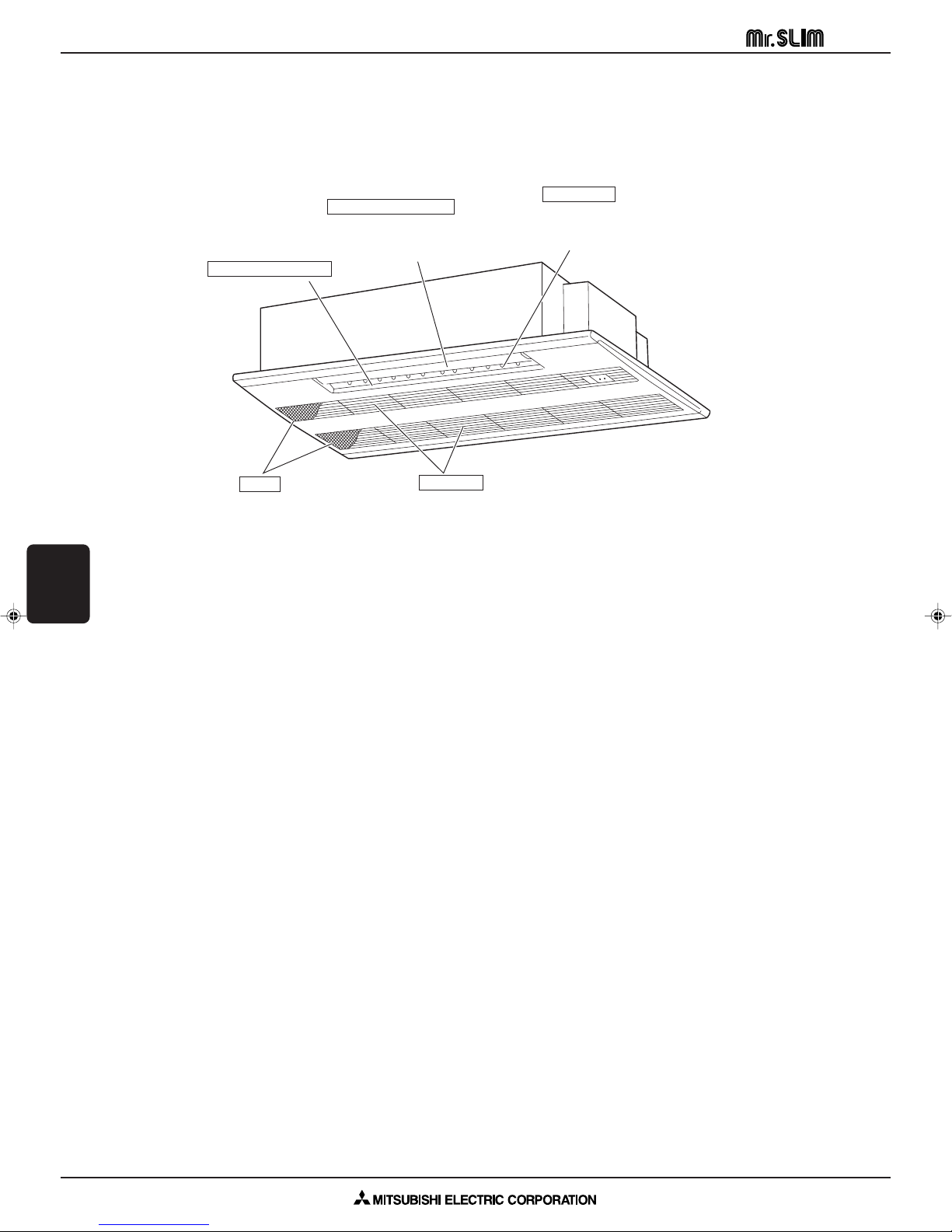
A.6.1 FEATURES
● Indoor (Main) Unit In case of PMH-P2BA
CEILING
CASSETTE PM
1. QUIET AS A MOUSE AND AS INCONSPICUOUS AS ONE TOO, THE PMH-P SERIES IS AN ATTRACTIVE, LIGHTWEIGHT MODEL THAT MOUNTS DIRECTLY INTO THE CEILING, BLENDING ALMOST SEAMLESSLY WITH NEARLY
FEATURES
ANY INTERIOR.
2. FRESH AIR INTAKE
Auto Air Swing Vane
Disperses air flow up and
down and adjusts the angle
of air flow direction.
Horizontal Air Outlet
Filters
Remove dust
and pollutants
from inhaled air.
Air recycled indefinitely can become stale and stagnant with air quality suffering significantly. Fresh air is the answer
and it is for this reason that the PMH-P series takes in air directly from outdoors. This fresh air intake allows you to
enjoy the comfort of crisp, refreshing air in the confines of your living or working space.
Air intake
Inhales air from room.
Guide vane
Air flow can be changed to
horizontally by moving the Guide
vane to the left or right.
3. LIGHT AND COMPACT
The main unit weighs a measly 14kg and the panel a mere 3kg. This makes the PMH-P series one of the lightest in the
industry. The unit size is also quite small, having been standardized to a strikingly compact 854mm. All of this helps
make the chore of installation and maintenance that much simpler and easier.
4. AESTHETICALLY PLEASING
Nothing ruins the look of a carefully decorated room more than a poorly designed, bulky air conditioner. With the PMHP series, there is no need to worry. The unit mounts directly into the ceiling barely protruding into the living space for a
pleasant, stylish aesthetic.
A-282
Page 3

CEILING CASSETTE PM SERIES Heat Pump R407C PMH-P1BA
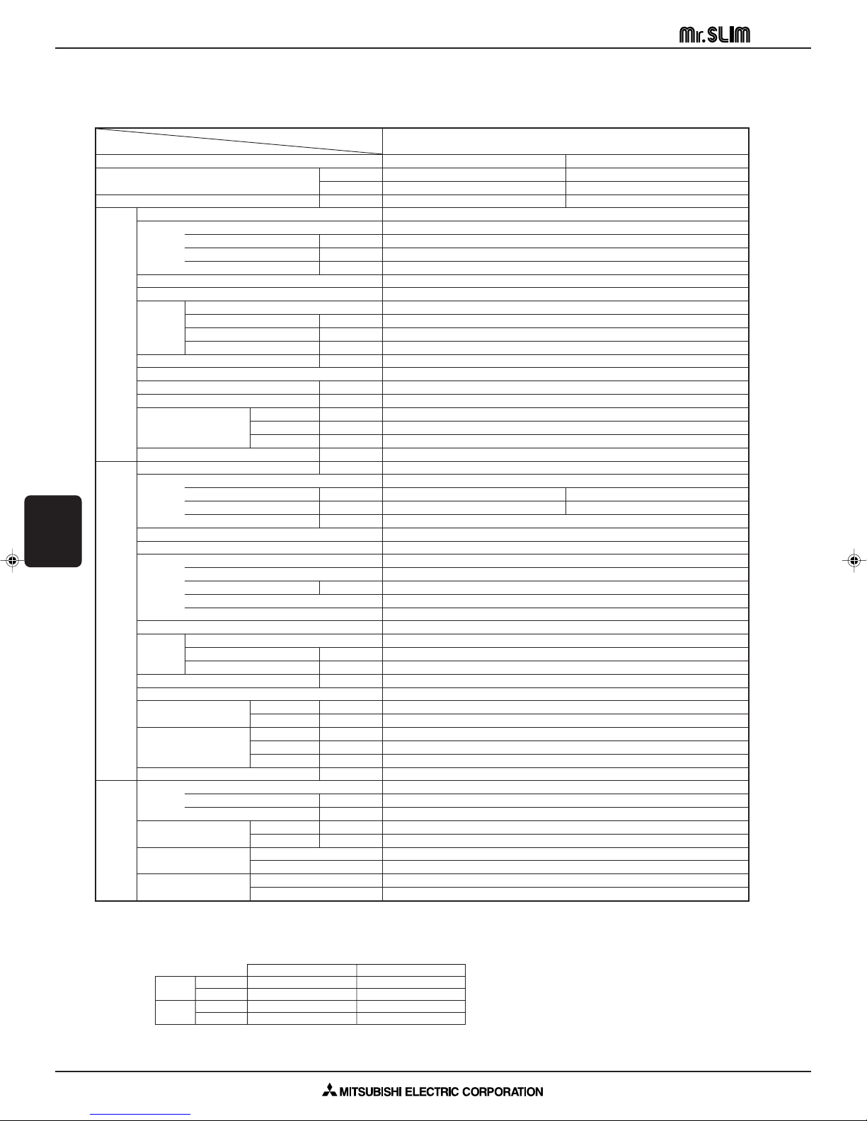
A.6.2 SPECIFICATIONS
A.6.2.1 Heat Pump (Refrigerant R407C)
Item
Function
Capacity
Total input kW
Model name
Power supply (phase, cycle,voltage)
External finish
Heat exchanger
Fan
Indoor unit
Booster heater kW
Operation control & Thermostat
Noise level (Lo-Mi2-Mi1-Hi) dB
Unit drain pipe I.D. mm (in.)
Dimensions
Weight kg (lbs.)
Model name
Power supply (phase, cycle, voltage)
External finish
Refrigerant control
Compressor
Heat exchanger
Outdoor unit
Fan Fan motor output kW
Crankcase heater W
Defrost method
Noise level
Dimensions
Weight kg (lbs.)
Refrigerant
Pipe size O.D.
Connection method
Refrigerant piping
Between the indoor &
outdoor units
NOTE: 1. Rating conditions (ISO T1)
2. Guaranteed operating range
Input kW
Running current A
Starting current A
Fan (drive) o No.
Fan motor output kW
Air flow (Lo-Mi2-Mi1-Hi)
External static pressure Pa (mmAq)
W mm (in.)
D mm (in.)
H mm (in.)
Input kW
Running current A
Starting current A
Model
Motor output kW
Starter type
Protection devices
Fan (drive) o No.
Air flow
Cooling dB
Heating dB
W mm (in.)
D mm (in.)
H mm (in.)
Charge kg (lbs.)
Oil (Model) L
Cooling : Indoor : D.B. 27: (80˚F), W.B. 19: (66˚F) Outdoor : D.B. 35: (95˚F), W.B. 24: (75˚F)
Heating : Indoor : D.B. 20: (68˚F) Outdoor : D.B. 7: (45˚F), W.B. 6: (43˚F)
Refrigerant piping length (one way) : 5m (16ft)
Upper limit D.B. 35˚C, W.B. 22.5˚C D.B. 46˚C
Cooling
Lower limit D.B. 19˚C, W.B. 15˚C D.B. -5˚C
Upper limit D.B. 28˚C D.B. 24˚C, W.B. 18˚C
Heating
Lower limit D.B. 17˚C D.B. -11˚C, W.B. -12˚C
Liquid mm (in.)
Gas mm (in.)
Indoor side
Outdoor side
Height difference
Piping length
Indoor Outdoor
Btu/h
K / min (CFM)
K / min (CFM)
Model
W
PMH-P1BA
Cooling Heating
10,700 11,600
3,150 3,400
1.15 1.06
PMH-P1BA
Single phase, 50Hz, 220-230-240V
0.04
0.19
0.21
Galvanized sheets with gray heat insulation, grille munsell 0.98Y 8.99/0.63
Plate fin coil
Line flow fan (direct) o 1
0.028
6.3-6.8-7.6-8.4 (222-240-268-297)
0 (direct blow)
–
Remote controller & built-in
29-31-33-35
26 (1)
UNIT : 812 (31-31/32) PANEL : 1000 (39-3/8)
UNIT : 395 (15-9/16) PANEL : 470 (18-1/2)
UNIT : 230 (9-1/16) PANEL : 30 (1-3/16)
UNIT : 14 (31) PANEL : 3.0 (6.6)
PUH-P1VGAA
Single phase, 50Hz, 220-230-240V
1.11 1.02
4.92 4.52
30
Munsell 5Y 7/1
Linear expansion valve
Hermetic
RE189VHSMT
0.9
Line start
Internal thermostat, HP switch, Discharge thermo.
Plate fin coil
Propeller (direct) o 1
0.070
45 (1,590)
30
Reverse cycle
46
48
900 (35-7/16)
330+20 (13+3/4)
650 (25-5/8)
50 (110)
R407C
1.7 (3.7)
0.57 (Ester) MEL56
6.35 (1/4)
12.7 (1/2)
Flared
Flared
Max. 30m
Max. 30m
3. Above data based on indicated voltage
Indoor unit Single phase 240V 50Hz
Outdoor unit Single phase 240V 50Hz
CEILING
CASSETTE PM
SPECIFICATIONS
A-283
Page 4
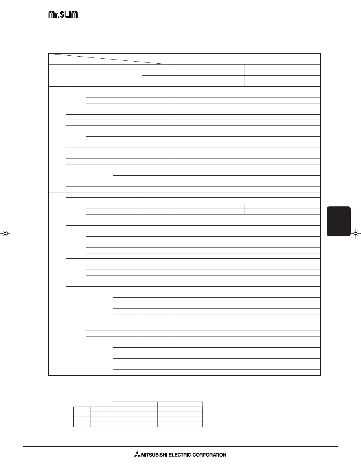
CEILING CASSETTE PM SERIES Heat Pump R407C PMH-P1.6BA
Item
Function
Capacity Btu/h
Total input kW
Indoor unit
CEILING
CASSETTE PM
SPECIFICATIONS
Outdoor unit
Refrigerant piping
NOTE: 1. Rating conditions (ISO T1)
Model
PMH-P1.6BA
Cooling Heating
15,000 17,100
W
4,400 5,000
1.65 1.70
Model name
Power supply (phase, cycle,voltage)
Single phase, 50Hz, 220-230-240V
PMH-P1.6BA
Input kW
Running current A
Starting current A
External finish
Heat exchanger
Fan (drive) o No.
Fan
Fan motor output kW
Air flow (Lo-Mi2-Mi1-Hi)
External static pressure Pa (mmAq)
K / min (CFM)
Galvanized sheets with gray heat insulation, grille munsell 0.98Y 8.99/0.63
Plate fin coil
Line flow fan (direct) o 1
7.0-8.0-9.0-10.0 (247-282-318-353)
0 (direct blow)
Booster heater kW
Operation control & Thermostat
Noise level (Lo-Mi2-Mi1-Hi) dB
Remote controller & built-in
34-36-38-40
Unit drain pipe I.D. mm (in.)
Dimensions
D mm (in.)
H mm (in.)
Weight kg (lbs.)
Model name
Power supply (phase, cycle, voltage)
Input kW
Running current A
W mm (in.)
Single phase, 50Hz, 220-230-240V / 3 phases, 50Hz, 380-400-415V (4wires)
UNIT : 812 (31-31/32) PANEL : 1,000 (39-3/8)
UNIT : 395 (15-9/16) PANEL : 470 (18-1/2)
UNIT : 230 (9-1/16) PANEL : 30 (1-3/16)
UNIT : 14 (31) PANEL : 3.0 (6.6)
PUH-P1.6VGAA / P1.6YGAA
1.59 1.64
7.36 / 2.49 7.59 / 2.56
Starting current A
External finish
Refrigerant control
Munsell 5Y 7/1
Linear expansion valve
Compressor
Model
RE277VHSMT / RE277YFKM
Motor output kW
Starter type
Heat exchanger
Protection devices
Fan (drive) o No.
Internal thermostat, HP switch, Discharge thermo. / Thermal relay, HP switch, Discharge thermo.
Plate fin coil
Propeller (direct) o 1
Fan Fan motor output kW
Air flow
K / min (CFM)
Crankcase heater W
Defrost method
Noise level
Dimensions
Cooling dB
Heating dB
W mm (in.)
D mm (in.)
H mm (in.)
Reverse cycle
900 (35-7/16)
330+20 (13+3/4)
650 (25-5/8)
Weight kg (lbs.)
Refrigerant
Charge kg (lbs.)
Oil (Model) L
Pipe size O.D.
Connection method
Between the indoor &
outdoor units
Cooling : Indoor : D.B. 27: (80˚F), W.B. 19: (66˚F) Outdoor : D.B. 35: (95˚F), W.B. 24: (75˚F)
Heating : Indoor : D.B. 20: (68˚F) Outdoor : D.B. 7: (45˚F), W.B. 6: (43˚F)
Refrigerant piping length (one way) : 5m (16ft)
2. Guaranteed operating range
Upper limit D.B. 35˚C, W.B. 22.5˚C D.B. 46˚C
Cooling
Lower limit D.B. 19˚C, W.B. 15˚C D.B. -5˚C
Upper limit D.B. 28˚C D.B. 24˚C, W.B. 18˚C
Heating
Lower limit D.B. 17˚C D.B. -11˚C, W.B. -12˚C
Liquid mm (in.)
Gas mm (in.)
Indoor side
Outdoor side
Height difference
Piping length
Indoor Outdoor
0.57 (Ester) MEL56
15.88 (5/8)
3. Above data based on indicated voltage
Indoor unit Single phase 240V 50Hz
Outdoor unit Single phase 240V 50Hz / 3 phases 415V 50Hz
0.06
0.29
0.32
0.028
–
26 (1)
36 / 20
Hermetic
1.3
Line start
0.070
45 (1,590)
30
47
49
55 (121)
R407C
2.5 (5.5)
9.52 (3/8)
Flared
Flared
Max. 40m
Max. 40m
A-284
Page 5
CEILING CASSETTE PM SERIES Heat Pump R407C PMH-P2BA
Item
Function
Capacity
Btu/h
Total input kW
Model name
Power supply (phase, cycle,voltage)
Input kW
Running current A
Starting current A
External finish
Heat exchanger
Fan (drive) o No.
Fan
Indoor unit
Booster heater kW
Fan motor output kW
Air flow (Lo-Mi2-Mi1-Hi)
K / min (CFM)
External static pressure Pa (mmAq)
Operation control & Thermostat
Noise level (Lo-Mi2-Mi1-Hi) dB
Unit drain pipe I.D. mm (in.)
W mm (in.)
Dimensions
D mm (in.)
H mm (in.)
Weight kg (lbs.)
Model name
Power supply (phase, cycle, voltage)
Input kW
Running current A
Starting current A
External finish
Refrigerant control
Compressor
Model
Motor output kW
Starter type
Protection devices
Heat exchanger
Outdoor unit
Fan Fan motor output kW
Fan (drive) o No.
Air flow
K / min (CFM)
Crankcase heater W
Defrost method
Noise level
Cooling dB
Heating dB
W mm (in.)
Dimensions
D mm (in.)
H mm (in.)
Weight kg (lbs.)
Refrigerant
Charge kg (lbs.)
Oil (Model) L
Pipe size O.D.
Connection method
Refrigerant piping
Between the indoor &
outdoor units
NOTE: 1. Rating conditions (ISO T1)
Cooling : Indoor : D.B. 27: (80˚F), W.B. 19: (66˚F) Outdoor : D.B. 35: (95˚F), W.B. 24: (75˚F)
Heating : Indoor : D.B. 20: (68˚F) Outdoor : D.B. 7: (45˚F), W.B. 6: (43˚F)
Refrigerant piping length (one way) : 5m (16ft)
2. Guaranteed operating range
Upper limit D.B. 35˚C, W.B. 22.5˚C D.B. 46˚C
Cooling
Lower limit D.B. 19˚C, W.B. 15˚C D.B. -5˚C
Upper limit D.B. 28˚C D.B. 24˚C, W.B. 18˚C
Heating
Lower limit D.B. 17˚C D.B. -11˚C, W.B. -12˚C
Liquid mm (in.)
Gas mm (in.)
Indoor side
Outdoor side
Height difference
Piping length
Indoor Outdoor
Model
W
PMH-P2BA
Cooling Heating
18,400 21,450
5,400 6,250
2.35 2.42
PMH-P2BA
Single phase, 50Hz, 220-230-240V
0.06
0.29
0.32
Galvanized sheets with gray heat insulation, grille munsell 0.98Y 8.99/0.63
Plate fin coil
Line flow fan (direct) o 1
0.028
8.0-9.0-10.0-11.0 (282-318-353-388)
0 (direct blow)
–
Remote controller & built-in
36-38-40-42
26 (1)
UNIT : 812 (31-31/32) PANEL : 1,000 (39-3/8)
UNIT : 395 (15-9/16) PANEL : 470 (18-1/2)
UNIT : 230 (9-1/16) PANEL : 30 (1-3/16)
UNIT : 14 (31) PANEL : 3.0 (6.6)
PUH-P2VGAA / P2YGAA
Single phase, 50Hz, 220-230-240V / 3 phases, 50Hz, 380-400-415V (4wires)
2.29 2.36
10.26 / 3.70 10.57 / 3.82
62 / 31
Munsell 5Y 7/1
Linear expansion valve
Hermetic
NE36VMJMT / NE36YEKMT
1.6
Line start
Internal thermostat, HP switch, Discharge thermo. / Thermal relay, HP switch, Discharge thermo.
Plate fin coil
Propeller (direct) o 1
0.070
55 (1,940)
38
Reverse cycle
48
49
900 (35-7/16)
330+20 (13+3/4)
855 (33-5/8)
71 (157)
R407C
2.6 (5.7)
1.2 (Ester) MEL56
9.52 (3/8)
15.88 (5/8)
Flared
Flared
Max. 40m
Max. 40m
3. Above data based on indicated voltage
Indoor unit Single phase 240V 50Hz
Outdoor unit Single phase 240V 50Hz / 3 phases 415V 50Hz
CEILING
CASSETTE PM
SPECIFICATIONS
A-285
Page 6
CEILING CASSETTE PM SERIES Heat Pump R407C PMH-P1/P1.6/P2BA
A.6.3 ELECTRICAL DATA
A.6.3.1 Heat Pump (Refrigerant R407C)
Indoor unit ...... 220V 50Hz Single phase Outdoor unit .... 220V 50Hz Single phase / 380V 50Hz 3 phases
Model
Mode
Capacity (W)
Total Input (kW)
Indoor unit
Outdoor unit
Indoor unit ...... 230V 50Hz Single phase Outdoor unit .... 230V 50Hz Single phase / 400V 50Hz 3 phases
Model
CEILING
CASSETTE PM
ELECTRICAL DATA
Mode
Capacity (W)
Total Input (kW)
Indoor unit
Outdoor unit
Indoor unit
Outdoor unit
(In + Out)
(In + Out + Heater)
Input (kW)
Current (A)
Starting current (A)
Current (A)
Indoor unit
Outdoor unit
(In + Out)
(In + Out + Heater)
Input (kW)
Current (A)
Starting current (A)
Current (A)
PMH-P1BA
PUH-P1VGAA
27
Heat
3,300
1.04
0.04
0.19
27
4.93
Cool
3,050
1.13
0.04
0.19
5.37
PMH-P1BA
PUH-P1VGAA
29
Heat
3,350
1.05
0.04
0.19
29
4.72
Cool
3,100
1.14
0.04
0.19
5.13
PMH-P1.6BA
PUH-P1.6VGAA
33
Heat
4,900
1.58
0.06
0.29
33
8.28
Cool
4,300
1.54
0.06
0.29
8.03
PMH-P1.6BA
PUH-P1.6VGAA
35
Heat
4,950
1.64
0.06
0.29
35
7.92
Cool
4,350
1.59
0.06
0.29
7.68
PMH-P2BA
PUH-P1.6YGAA PUH-P2VGAA PUH-P2YGAA
18
Heat
4,900
1.58
0.06
0.29
18
2.80
Cool
5,300
2.27
0.06
0.29
62
11.19
Heat
6,150
2.32
0.06
0.29
62
11.53
Cool
5,300
2.27
0.06
0.29
31
4.05
Heat
6,150
2.32
0.06
0.29
31
4.17
Cool
4,300
1.54
0.06
0.29
2.71
PMH-P2BA
PUH-P1.6YGAA PUH-P2VGAA PUH-P2YGAA
19
Heat
4,950
1.64
0.06
0.29
19
2.66
Cool
5,350
2.31
0.06
0.29
62
10.71
Heat
6,200
2.37
0.06
0.29
62
11.03
Cool
5,350
2.31
0.06
0.29
31
3.84
Heat
6,200
2.37
0.06
0.29
31
3.96
Cool
4,350
1.59
0.06
0.29
2.58
Indoor unit ...... 240V 50Hz Single phase Outdoor unit .... 240V 50Hz Single phase / 415V 50Hz 3 phases
Model
Indoor unit
Outdoor unit
Mode
Capacity (W)
Total Input (kW)
(In + Out)
(In + Out + Heater)
Input (kW)
Current (A)
Indoor unit
Starting current (A)
Current (A)
Outdoor unit
A-286
PMH-P1BA
PUH-P1VGAA
30
Heat
3,400
1.06
0.04
0.19
30
4.52
Cool
3,150
1.15
0.04
0.19
4.92
PMH-P1.6BA
PUH-P1.6VGAA
36
Heat
5,000
1.70
0.06
0.29
36
7.59
Cool
4,400
1.65
0.06
0.29
7.36
PMH-P2BA
PUH-P1.6YGAA PUH-P2VGAA PUH-P2YGAA
20
Heat
5,000
1.70
0.06
0.29
20
2.56
Cool
5,400
2.35
0.06
0.29
62
10.26
Heat
6,250
2.42
0.06
0.29
62
10.57
Cool
5,400
2.35
0.06
0.29
31
3.70
Heat
6,250
2.42
0.06
0.29
31
3.82
Cool
4,400
1.65
0.06
0.29
2.49
Page 7
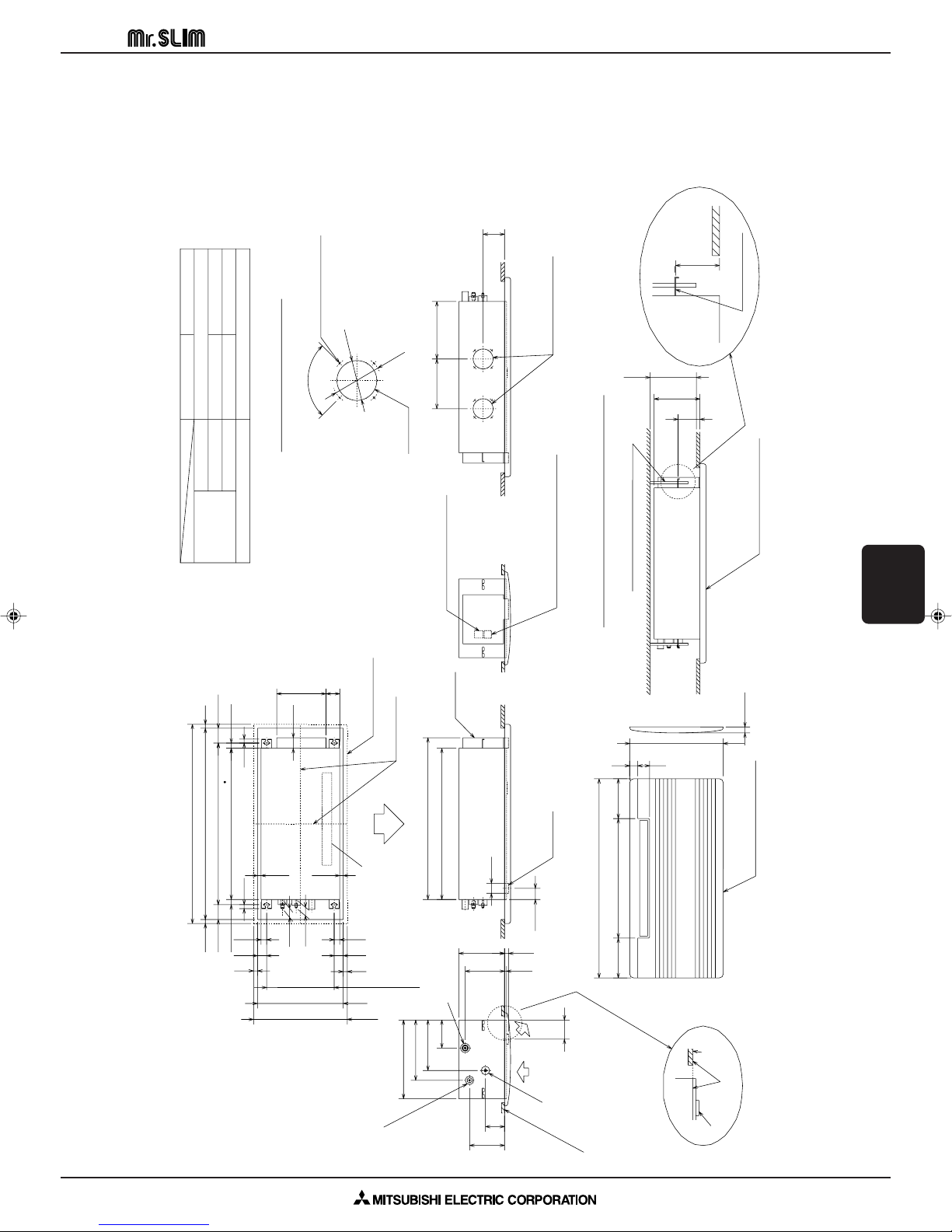
Details of fresh air intake hole
Knock out
4-{2.8 Burring hole
Flesh air intake hole
110
230
235 or more
110
suspension bolt(M10 or W3/8)
Panel(grille):PMP-40BM
Installation space required around indoor unit
mounting plate
176
Panel(grille):PMP-40BM
Lower view
60 40
200600200
To p
Air outlet(lower)
46
43
2828
20
26
20
53
69
247
30
Right side
outer line of grille
center of unit
75926
811 suspension bolt pitch74.5
960 ceiling opening20 20
1000 outer side of grille
17.517.5
45
340 suspension bolt pitch
45
430 ceiling opening
470 outer side of grille
20
20
74.5
Terminal block for
indoor/outdoor connection
Terminal block for remote controller
812
96
Left side
Front
drain pan
elect box
Drainage pipe
PVC pipe:VP-20[O.D.
{25]
Refrigerant pipe(gas)
Refrigerant
pipe(liquid)
ceiling panel
drain pan
ceiling
panel
PVC pipe:VP-20[O.D.
{25(1")]
O.D.{35
O.D.{12.7(1/2") O.D.{15.88(5/8")
O.D.{6.35(1/4") O.D.{9.52(3/8")
PMH-P1BA PMH-P1.6 / P2BA
Drainage piping
Gas pipe
Liquid pipe
pipe cover
Refrigerant
piping
1000 outer side of grille
470 outer side of grille
{50
(56)
230
(96)
(20)
(10)
302
254
198
141
759
395
90-
{
122
{
100
108
250 288.5
same line
CEILING CASSETTE PM SERIES PMH-P1/P1.6/P2BA
A.6.4 OUTLINES AND DIMENSIONS
PMH-P1BA
PMH-P1.6BA
PMH-P2BA
Unit: mm
CEILING
CASSETTE PM
OUTLINES AND DIMENSIONS
A-287
Page 8
CEILING CASSETTE PM SERIES PMH-P1/P1.6/P2BA
(BLU)
REMOTECN90 CN32
12
CN22
CONTROLLER
12346
FAN
(WHT)
LED1
ZNR
T
FUSE
POWER
(RED)
CN03
5
3
1
CN2L
5
LED3
J11
J12
J13
J14
J15
J21
J22
J23
J24
SW2SW1SWE
OFF
ON
1
2
3
4
5
6
PIPE
CN29
(BLK)
1
2
(WHT)
(WHT)
(RED)
(WHT)
CN6V
CN21
CN20
CN31
VANE
INTAKE
LIQUID
D.SENSOR
1
2
1
2
3
2
1
LED2
TH1
TH5
5
4
2
1
MV
3
TH2
CN41
TB6
21
CN2
1
2
TB5
DS
YLW
ORN
RED
GRN
BLU
BLU
ORN
YLW
BRN
BRN
BLK
BLK
BLK
BLK
BLK
BLK
BLK
BLK
R.B
I.B
5
MF
TRANSMISSION WIRES DC12V
TB1
S2
S3
S1
L
N
TB1
S1
S3
S2
N
L3
L2
L1
S3
TB4
S2
S1
OUTDOOR UNIT
<PUH-P1, P1.6, P2VGAA>
POWER SUPPLY
~/N(1PHASE)
220 - 230 - 240V 50Hz
<PUH-P1.6, P2YGAA>
POWER SUPPLY
3N~(3PHASE 4WIRES)
380 - 400 - 415V 50Hz
See fig : w1
BLU
BLU
DP
3
1
D.U. M
CNP
(YLW)
X1
X1
SW2
ON
OFF
4231
J21 J22 J23 J24
ON
OFF
4231
ON
OFF
4231
J21 J22 J23 J24
J21 J22 J23 J24
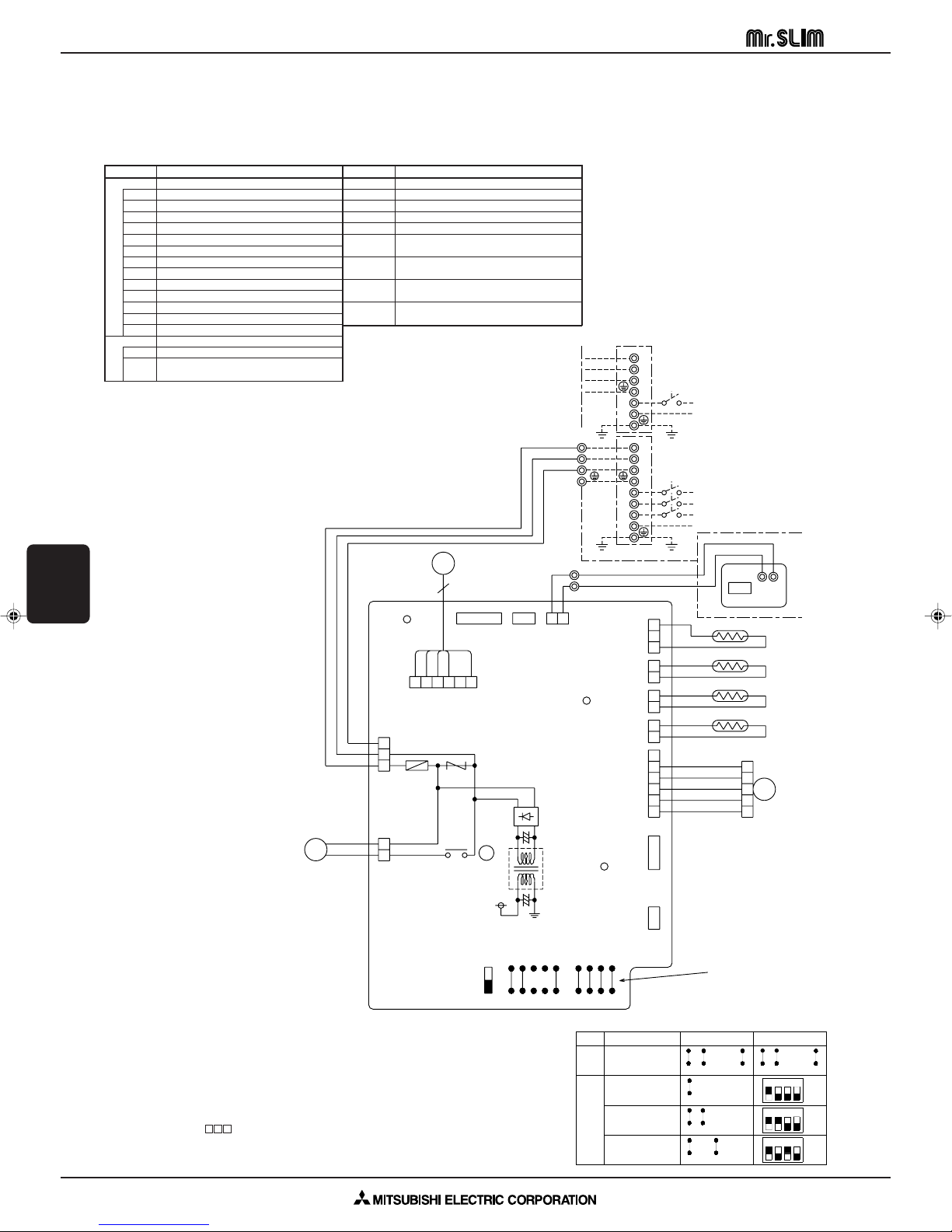
PMH-P1BA
PMH-P2BA
PMH-P1.6BA
J11 J12 J13 J14 J15 J11 J12 J13 J14 J15
PMH P1/P1.6/P2BA
SW1
MODELS
Manufacture
Service board
<w1>
A.6.5 WIRING DIAGRAM
PMH-P1BA, PMH-P1.6BA, PMH-P2BA
SYMBOL
I.B
CN2L
CN32
CN41
FUSE
LED1
LED2
LED3
SW1
SW2
SWE
T
X1
ZNR
R.B
CN2
TB6
INDOOR CONTROLLER BOARD
CONNECTOR(LOSSNAY)
CONNECTOR(REMOTE SWITCH)
CONNECTOR(HA TERMINAL-A)
FUSE (6.3A, 250V)
POWER SUPPLY(I.B)
POWER SUPPLY(R.B)
TRANSMISSION(INDOOR-OUTDOOR)
JUMPER WIRE(MODEL SELECTION)
JUMPER WIRE(CAPACITY CORD)
SWITCH(EMERGENCY OPERATION)
TRANSFORMER
RELAY(DRAIN PUMP)
VARISTOR
REMOTE CONTROLLER BOARD
CONNECTOR(SCHEDULE TIMER)
TERMINAL BLOCK(REMOTE
CONTROLLER TRANSMISSION LINE)
NAME
SYMBOL
DP
DS
MF
MV
TB4
TB5
TH1
TH2
TH5
DRAIN-UP MACHINE
DRAIN SENSOR
FAN MOTOR
VANE MOTOR
TERMINAL BLOCK(INDOOR/OUTDOOR CONNECTING LINE)
TERMINAL BLOCK(REMOTE
CONTROLLER TRANSMISSION LINE)
ROOM TEMP.THERMISTOR
(0:/15k",25:/5.4k" DETECT)
PIPE TEMP.THERMISTOR/LIQUID
(0:/15k",25:/5.4k" DETECT)
COND./EVA.TEMP.THERMISTOR
(0:/15k",25:/5.4k" DETECT)
NAME
CEILING
CASSETTE PM
WIRING DIAGRAM
NOTE:
1. Since the outdoor side electric wiring may change be sure to check the
outdoor unit electric wiring for servicing.
2. Indoor and outdoor connecting wires are made with polarities,make wiring
matching terminal numbers (S1,S2,S3).
3. Symbols used in wiring diagram above are,
/ : Terminal block, : Connector.
Please set the voltage using the remote controller.
For the setting method, please refer to the indoor unit Installation Manual.
A-288
Page 9
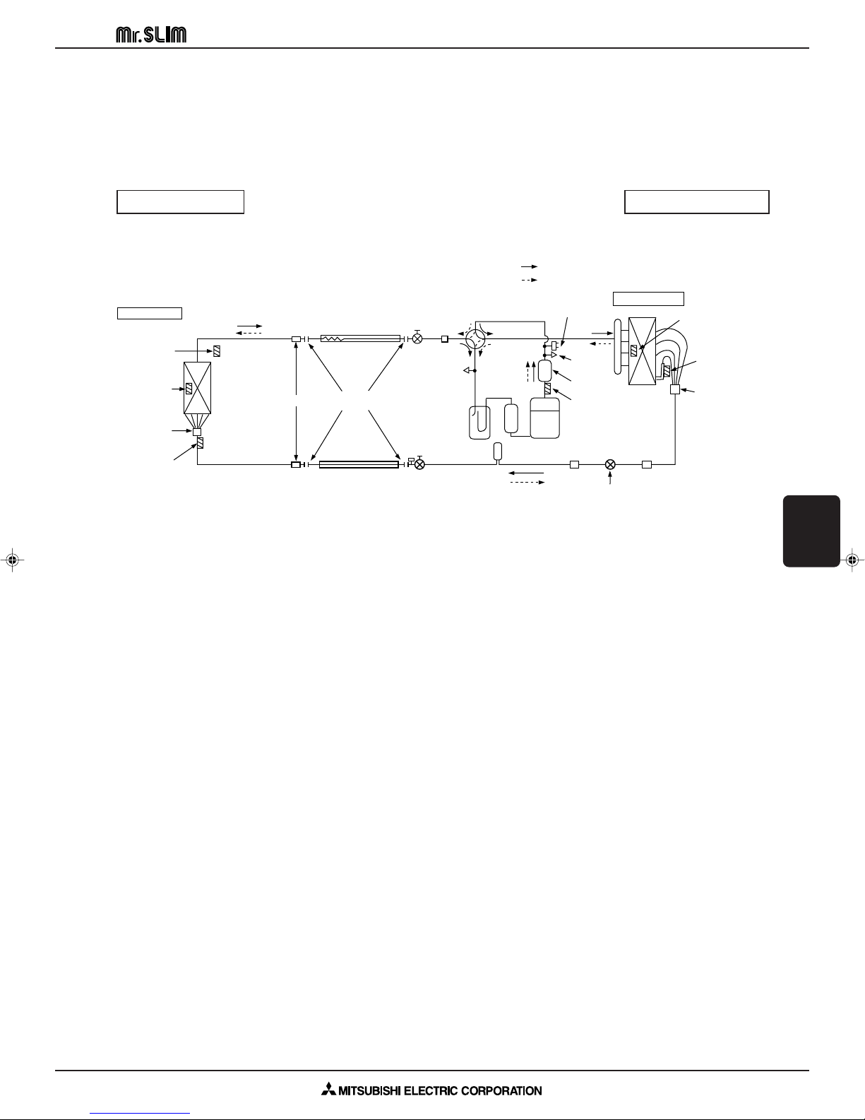
CEILING CASSETTE PM SERIES PMH-P1/P1.6/P2BA
Indoor unit
Refrigerant pipe
15.88mm([5/8"):PMH-P1/1.6/2BA
(with heat insulator)
Flexible tube
Ball valve
Strainer
4-way valve
Muffler
Service
port
Service
port
High pressure
protect switch
Outdoor unit
Strainer Strainer
Compressor
Accumulator
Drier
Stop valve
(with service port)
Refrigerant pipe
9.52mm([3/8"):PMH-P1/1.6/2BA
(with heat insulator)
Distributor
with
strainer
Distributor
with
strainer
Thermistor
(TH1)
Thermistor
(TH5)
Thermistor
(TH4)
Thermistor
(TH6)
Thermistor
(TH3)
Thermistor
(TH2)
Strainer
Flared
connection
<4-way valve solenoid coil>
Heating ON
Cooling OFF
Refrigerant flow in cooling
Refrigerant flow in heating
Linear expansion valve
A.6.6 REFRIGERANT SYSTEM DIAGRAM
PMH-P1BA / PUH-P1VGAA
PMH-P1.6BA / PUH-P1.6VGAA, PUH-P1.6YGAA
PMH-P2BA / PUH-P2VGAA, PUH-P2YGAA
INDOOR UNIT OUTDOOR UNIT
Unit: mm
A-289
CEILING
CASSETTE PM
REFRIGERANT SYSTEM DIAGRAM
Page 10

CEILING CASSETTE PM SERIES PMH-P1BA
A.6.7 PERFORMANCE DATA
COOLING CAPACITY (240V)
PMH-P1BA
CAPACITY : 3,150 W INPUT : 1.15 kW SHF : 0.77
Indoor
intake air
DB
(:)
20 16 3,119 2,089 0.67 0.92 3,024 2,026 0.67 0.97 2,930 1,963 0.67 1.03
20 18 3,339 1,836 0.55 0.94 3,245 1,784 0.55 0.99 3,134 1,724 0.55 1.06
20 20 3,591 1,544 0.43 0.97 3,512 1,510 0.43 1.01 3,418 1,470 0.43 1.08
22 16 3,119 2,339 0.75 0.92 3,024 2,268 0.75 0.97 2,930 2,197 0.75 1.03
22 18 3,339 2,104 0.63 0.94 3,245 2,044 0.63 0.99 3,134 1,975 0.63 1.06
22 20 3,591 1,831 0.51 0.97 3,512 1,791 0.51 1.01 3,418 1,743 0.51 1.08
24 16 3,119 2,588 0.83 0.92 3,024 2,510 0.83 0.97 2,930 2,431 0.83 1.03
24 18 3,339 2,371 0.71 0.94 3,245 2,304 0.71 0.99 3,134 2,225 0.71 1.06
24 20 3,591 2,119 0.59 0.97 3,512 2,072 0.59 1.01 3,418 2,016 0.59 1.08
24 22 3,827 1,799 0.47 0.99 3,749 1,762 0.47 1.05 3,654 1,717 0.47 1.12
26 16 3,119 2,838 0.91 0.92 3,024 2,752 0.91 0.97 2,930 2,666 0.91 1.03
26 18 3,339 2,638 0.79 0.94 3,245 2,563 0.79 0.99 3,134 2,476 0.79 1.06
26 20 3,591 2,406 0.67 0.97 3,512 2,353 0.67 1.01 3,418 2,290 0.67 1.08
26 22 3,827 2,105 0.55 0.99 3,749 2,062 0.55 1.05 3,654 2,010 0.55 1.12
28 16 3,119 3,087 0.99 0.92 3,024 2,994 0.99 0.97 2,930 2,900 0.99 1.03
28 18 3,339 2,905 0.87 0.94 3,245 2,823 0.87 0.99 3,134 2,727 0.87 1.06
28 20 3,591 2,693 0.75 0.97 3,512 2,634 0.75 1.01 3,418 2,563 0.75 1.08
CEILING
CASSETTE PM
PERFORMANCE DATA
28 22 3,827 2,411 0.63 0.99 3,749 2,362 0.63 1.05 3,654 2,302 0.63 1.12
30 16 3,119 3,119 1.00 0.92 3,024 3,024 1.00 0.97 2,930 2,930 1.00 1.03
30 18 3,339 3,172 0.95 0.94 3,245 3,082 0.95 0.99 3,134 2,978 0.95 1.06
30 20 3,591 2,981 0.83 0.97 3,512 2,915 0.83 1.01 3,418 2,837 0.83 1.08
30 22 3,827 2,717 0.71 0.99 3,749 2,661 0.71 1.05 3,654 2,594 0.71 1.12
32 16 3,119 3,119 1.00 0.92 3,024 3,024 1.00 0.97 2,930 2,930 1.00 1.03
32 18 3,339 3,339 1.00 0.94 3,245 3,245 1.00 0.99 3,134 3,134 1.00 1.06
32 20 3,591 3,268 0.91 0.97 3,512 3,196 0.91 1.01 3,418 3,110 0.91 1.08
32 22 3,827 3,024 0.79 0.99 3,749 2,961 0.79 1.05 3,654 2,887 0.79 1.12
34 16 3,119 3,119 1.00 0.92 3,024 3,024 1.00 0.97 2,930 2,930 1.00 1.03
34 18 3,339 3,339 1.00 0.94 3,245 3,245 1.00 0.99 3,134 3,134 1.00 1.06
34 20 3,591 3,555 0.99 0.97 3,512 3,477 0.99 1.01 3,418 3,384 0.99 1.08
34 22 3,827 3,330 0.87 0.99 3,749 3,261 0.87 1.05 3,654 3,179 0.87 1.12
NOTE: CA: Capacity (W) SHC: Sensible heat capacity (W)
Indoor
intake air
WB
P.C.: Power consumption (kW) SHF: Sensible heat factor
CA SHC SHF P.C. CA SHC SHF P.C. CA SHC SHF P.C.
(:)
20 25 30
Outdoor intake air DB (:)
A-290
Page 11

CEILING CASSETTE PM SERIES PMH-P1BA
COOLING CAPACITY (240V)
PMH-P1BA
CAPACITY : 3,150 W INPUT : 1.15 kW SHF : 0.77
Indoor
intake air
DB
NOTE: CA: Capacity (W) SHC: Sensible heat capacity (W)
Indoor
intake air
WB
(:)
20 16 2,804 1,878 0.67 1.10 2,678 1,794 0.67 1.18 2,552 1,710 0.67 1.28
20 18 3,024 1,663 0.55 1.13 2,930 1,611 0.55 1.22 2,741 1,507 0.55 1.31
20 20 3,276 1,409 0.43 1.16 3,150 1,355 0.43 1.24 2,961 1,273 0.43 1.33
22 16 2,804 2,103 0.75 1.10 2,678 2,008 0.75 1.18 2,552 1,914 0.75 1.28
22 18 3,024 1,905 0.63 1.13 2,930 1,846 0.63 1.22 2,741 1,727 0.63 1.31
22 20 3,276 1,671 0.51 1.16 3,150 1,607 0.51 1.24 2,961 1,510 0.51 1.33
24 16 2,804 2,327 0.83 1.10 2,678 2,222 0.83 1.18 2,552 2,118 0.83 1.28
24 18 3,024 2,147 0.71 1.13 2,930 2,080 0.71 1.22 2,741 1,946 0.71 1.31
24 20 3,276 1,933 0.59 1.16 3,150 1,859 0.59 1.24 2,961 1,747 0.59 1.33
24 22 3,528 1,658 0.47 1.18 3,402 1,599 0.47 1.28 3,213 1,510 0.47 1.36
26 16 2,804 2,551 0.91 1.10 2,678 2,437 0.91 1.18 2,552 2,322 0.91 1.28
26 18 3,024 2,389 0.79 1.13 2,930 2,314 0.79 1.22 2,741 2,165 0.79 1.31
26 20 3,276 2,195 0.67 1.16 3,150 2,111 0.67 1.24 2,961 1,984 0.67 1.33
26 22 3,528 1,940 0.55 1.18 3,402 1,871 0.55 1.28 3,213 1,767 0.55 1.36
28 16 2,804 2,775 0.99 1.10 2,678 2,651 0.99 1.18 2,552 2,526 0.99 1.28
28 18 3,024 2,631 0.87 1.13 2,930 2,549 0.87 1.22 2,741 2,384 0.87 1.31
28 20 3,276 2,457 0.75 1.16 3,150 2,363 0.75 1.24 2,961 2,221 0.75 1.33
28 22 3,528 2,223 0.63 1.18 3,402 2,143 0.63 1.28 3,213 2,024 0.63 1.36
30 16 2,804 2,804 1.00 1.10 2,678 2,678 1.00 1.18 2,552 2,552 1.00 1.28
30 18 3,024 2,873 0.95 1.13 2,930 2,783 0.95 1.22 2,741 2,603 0.95 1.31
30 20 3,276 2,719 0.83 1.16 3,150 2,615 0.83 1.24 2,961 2,458 0.83 1.33
30 22 3,528 2,505 0.71 1.18 3,402 2,415 0.71 1.28 3,213 2,281 0.71 1.36
32 16 2,804 2,804 1.00 1.10 2,678 2,678 1.00 1.18 2,552 2,552 1.00 1.28
32 18 3,024 3,024 1.00 1.13 2,930 2,930 1.00 1.22 2,741 2,741 1.00 1.31
32 20 3,276 2,981 0.91 1.16 3,150 2,867 0.91 1.24 2,961 2,695 0.91 1.33
32 22 3,528 2,787 0.79 1.18 3,402 2,688 0.79 1.28 3,213 2,538 0.79 1.36
34 16 2,804 2,804 1.00 1.10 2,678 2,678 1.00 1.18 2,552 2,552 1.00 1.28
34 18 3,024 3,024 1.00 1.13 2,930 2,930 1.00 1.22 2,741 2,741 1.00 1.31
34 20 3,276 3,243 0.99 1.16 3,150 3,119 0.99 1.24 2,961 2,931 0.99 1.33
34 22 3,528 3,069 0.87 1.18 3,402 2,960 0.87 1.28 3,213 2,795 0.87 1.36
P.C.: Power consumption (kW) SHF: Sensible heat factor
CA SHC SHF P.C. CA SHC SHF P.C. CA SHC SHF P.C.
(:)
35 40 45
Outdoor intake air DB (:)
CEILING
CASSETTE PM
PERFORMANCE DATA
A-291
Page 12

CEILING CASSETTE PM SERIES PMH-P1.6BA
COOLING CAPACITY (240V)
PMH-P1.6BA
CAPACITY : 4,400 W INPUT : 1.65 kW SHF : 0.70
Indoor
intake air
DB
(:)
20 16 4,356 2,614 0.60 1.32 4,224 2,534 0.60 1.39 4,092 2,455 0.60 1.48
20 18 4,664 2,239 0.48 1.34 4,532 2,175 0.48 1.42 4,378 2,101 0.48 1.52
20 20 5,016 1,806 0.36 1.39 4,906 1,766 0.36 1.45 4,774 1,719 0.36 1.55
22 16 4,356 2,962 0.68 1.32 4,224 2,872 0.68 1.39 4,092 2,783 0.68 1.48
22 18 4,664 2,612 0.56 1.34 4,532 2,538 0.56 1.42 4,378 2,452 0.56 1.52
22 20 5,016 2,207 0.44 1.39 4,906 2,159 0.44 1.45 4,774 2,101 0.44 1.55
24 16 4,356 3,311 0.76 1.32 4,224 3,210 0.76 1.39 4,092 3,110 0.76 1.48
24 18 4,664 2,985 0.64 1.34 4,532 2,900 0.64 1.42 4,378 2,802 0.64 1.52
24 20 5,016 2,608 0.52 1.39 4,906 2,551 0.52 1.45 4,774 2,482 0.52 1.55
24 22 5,346 2,138 0.40 1.42 5,236 2,094 0.40 1.50 5,104 2,042 0.40 1.60
26 16 4,356 3,659 0.84 1.32 4,224 3,548 0.84 1.39 4,092 3,437 0.84 1.48
26 18 4,664 3,358 0.72 1.34 4,532 3,263 0.72 1.42 4,378 3,152 0.72 1.52
26 20 5,016 3,010 0.60 1.39 4,906 2,944 0.60 1.45 4,774 2,864 0.60 1.55
26 22 5,346 2,566 0.48 1.42 5,236 2,513 0.48 1.50 5,104 2,450 0.48 1.60
28 16 4,356 4,008 0.92 1.32 4,224 3,886 0.92 1.39 4,092 3,765 0.92 1.48
28 18 4,664 3,731 0.80 1.34 4,532 3,626 0.80 1.42 4,378 3,502 0.80 1.52
28 20 5,016 3,411 0.68 1.39 4,906 3,336 0.68 1.45 4,774 3,246 0.68 1.55
CEILING
CASSETTE PM
PERFORMANCE DATA
28 22 5,346 2,994 0.56 1.42 5,236 2,932 0.56 1.50 5,104 2,858 0.56 1.60
30 16 4,356 4,356 1.00 1.32 4,224 4,224 1.00 1.39 4,092 4,092 1.00 1.48
30 18 4,664 4,104 0.88 1.34 4,532 3,988 0.88 1.42 4,378 3,853 0.88 1.52
30 20 5,016 3,812 0.76 1.39 4,906 3,729 0.76 1.45 4,774 3,628 0.76 1.55
30 22 5,346 3,421 0.64 1.42 5,236 3,351 0.64 1.50 5,104 3,267 0.64 1.60
32 16 4,356 4,356 1.00 1.32 4,224 4,224 1.00 1.39 4,092 4,092 1.00 1.48
32 18 4,664 4,477 0.96 1.34 4,532 4,351 0.96 1.42 4,378 4,203 0.96 1.52
32 20 5,016 4,213 0.84 1.39 4,906 4,121 0.84 1.45 4,774 4,010 0.84 1.55
32 22 5,346 3,849 0.72 1.42 5,236 3,770 0.72 1.50 5,104 3,675 0.72 1.60
34 16 4,356 4,356 1.00 1.32 4,224 4,224 1.00 1.39 4,092 4,092 1.00 1.48
34 18 4,664 4,664 1.00 1.34 4,532 4,532 1.00 1.42 4,378 4,378 1.00 1.52
34 20 5,016 4,615 0.92 1.39 4,906 4,514 0.92 1.45 4,774 4,392 0.92 1.55
34 22 5,346 4,277 0.80 1.42 5,236 4,189 0.80 1.50 5,104 4,083 0.80 1.60
NOTE: CA: Capacity (W) SHC: Sensible heat capacity (W)
Indoor
intake air
WB
P.C.: Power consumption (kW) SHF: Sensible heat factor
CA SHC SHF P.C. CA SHC SHF P.C. CA SHC SHF P.C.
(:)
20 25 30
Outdoor intake air DB (:)
A-292
Page 13

CEILING CASSETTE PM SERIES PMH-P1.6BA
COOLING CAPACITY (240V)
PMH-P1.6BA
CAPACITY : 4,400 W INPUT : 1.65 kW SHF : 0.70
Indoor
intake air
DB
NOTE: CA: Capacity (W) SHC: Sensible heat capacity (W)
Indoor
intake air
WB
(:)
20 16 3,916 2,350 0.60 1.58 3,740 2,244 0.60 1.70 3,564 2,138 0.60 1.84
20 18 4,224 2,028 0.48 1.63 4,092 1,964 0.48 1.75 3,828 1,837 0.48 1.88
20 20 4,576 1,647 0.36 1.67 4,400 1,584 0.36 1.78 4,136 1,489 0.36 1.91
22 16 3,916 2,663 0.68 1.58 3,740 2,543 0.68 1.70 3,564 2,424 0.68 1.84
22 18 4,224 2,365 0.56 1.63 4,092 2,292 0.56 1.75 3,828 2,144 0.56 1.88
22 20 4,576 2,013 0.44 1.67 4,400 1,936 0.44 1.78 4,136 1,820 0.44 1.91
24 16 3,916 2,976 0.76 1.58 3,740 2,842 0.76 1.70 3,564 2,709 0.76 1.84
24 18 4,224 2,703 0.64 1.63 4,092 2,619 0.64 1.75 3,828 2,450 0.64 1.88
24 20 4,576 2,380 0.52 1.67 4,400 2,288 0.52 1.78 4,136 2,151 0.52 1.91
24 22 4,928 1,971 0.40 1.70 4,752 1,901 0.40 1.83 4,488 1,795 0.40 1.95
26 16 3,916 3,289 0.84 1.58 3,740 3,142 0.84 1.70 3,564 2,994 0.84 1.84
26 18 4,224 3,041 0.72 1.63 4,092 2,946 0.72 1.75 3,828 2,756 0.72 1.88
26 20 4,576 2,746 0.60 1.67 4,400 2,640 0.60 1.78 4,136 2,482 0.60 1.91
26 22 4,928 2,365 0.48 1.70 4,752 2,281 0.48 1.83 4,488 2,154 0.48 1.95
28 16 3,916 3,603 0.92 1.58 3,740 3,441 0.92 1.70 3,564 3,279 0.92 1.84
28 18 4,224 3,379 0.80 1.63 4,092 3,274 0.80 1.75 3,828 3,062 0.80 1.88
28 20 4,576 3,112 0.68 1.67 4,400 2,992 0.68 1.78 4,136 2,812 0.68 1.91
28 22 4,928 2,760 0.56 1.70 4,752 2,661 0.56 1.83 4,488 2,513 0.56 1.95
30 16 3,916 3,916 1.00 1.58 3,740 3,740 1.00 1.70 3,564 3,564 1.00 1.84
30 18 4,224 3,717 0.88 1.63 4,092 3,601 0.88 1.75 3,828 3,369 0.88 1.88
30 20 4,576 3,478 0.76 1.67 4,400 3,344 0.76 1.78 4,136 3,143 0.76 1.91
30 22 4,928 3,154 0.64 1.70 4,752 3,041 0.64 1.83 4,488 2,872 0.64 1.95
32 16 3,916 3,916 1.00 1.58 3,740 3,740 1.00 1.70 3,564 3,564 1.00 1.84
32 18 4,224 4,055 0.96 1.63 4,092 3,928 0.96 1.75 3,828 3,675 0.96 1.88
32 20 4,576 3,844 0.84 1.67 4,400 3,696 0.84 1.78 4,136 3,474 0.84 1.91
32 22 4,928 3,548 0.72 1.70 4,752 3,421 0.72 1.83 4,488 3,231 0.72 1.95
34 16 3,916 3,916 1.00 1.58 3,740 3,740 1.00 1.70 3,564 3,564 1.00 1.84
34 18 4,224 4,224 1.00 1.63 4,092 4,092 1.00 1.75 3,828 3,828 1.00 1.88
34 20 4,576 4,210 0.92 1.67 4,400 4,048 0.92 1.78 4,136 3,805 0.92 1.91
34 22 4,928 3,942 0.80 1.70 4,752 3,802 0.80 1.83 4,488 3,590 0.80 1.95
P.C.: Power consumption (kW) SHF: Sensible heat factor
CA SHC SHF P.C. CA SHC SHF P.C. CA SHC SHF P.C.
(:)
35 40 45
Outdoor intake air DB (:)
CEILING
CASSETTE PM
PERFORMANCE DATA
A-293
Page 14

CEILING CASSETTE PM SERIES PMH-P2BA
COOLING CAPACITY (240V)
PMH-P2BA
CAPACITY : 5,400 W INPUT : 2.35 kW SHF : 0.67
Indoor
intake air
DB
(:)
20 16 5,346 3,047 0.57 1.88 5,184 2,955 0.57 1.99 5,022 2,863 0.57 2.10
20 18 5,724 2,576 0.45 1.92 5,562 2,503 0.45 2.02 5,373 2,418 0.45 2.16
20 20 6,156 2,031 0.33 1.97 6,021 1,987 0.33 2.07 5,859 1,933 0.33 2.21
22 16 5,346 3,475 0.65 1.88 5,184 3,370 0.65 1.99 5,022 3,264 0.65 2.10
22 18 5,724 3,034 0.53 1.92 5,562 2,948 0.53 2.02 5,373 2,848 0.53 2.16
22 20 6,156 2,524 0.41 1.97 6,021 2,469 0.41 2.07 5,859 2,402 0.41 2.21
24 16 5,346 3,903 0.73 1.88 5,184 3,784 0.73 1.99 5,022 3,666 0.73 2.10
24 18 5,724 3,492 0.61 1.92 5,562 3,393 0.61 2.02 5,373 3,278 0.61 2.16
24 20 6,156 3,016 0.49 1.97 6,021 2,950 0.49 2.07 5,859 2,871 0.49 2.21
24 22 6,561 2,428 0.37 2.02 6,426 2,378 0.37 2.14 6,264 2,318 0.37 2.28
26 16 5,346 4,330 0.81 1.88 5,184 4,199 0.81 1.99 5,022 4,068 0.81 2.10
26 18 5,724 3,950 0.69 1.92 5,562 3,838 0.69 2.02 5,373 3,707 0.69 2.16
26 20 6,156 3,509 0.57 1.97 6,021 3,432 0.57 2.07 5,859 3,340 0.57 2.21
26 22 6,561 2,952 0.45 2.02 6,426 2,892 0.45 2.14 6,264 2,819 0.45 2.28
28 16 5,346 4,758 0.89 1.88 5,184 4,614 0.89 1.99 5,022 4,470 0.89 2.10
28 18 5,724 4,407 0.77 1.92 5,562 4,283 0.77 2.02 5,373 4,137 0.77 2.16
28 20 6,156 4,001 0.65 1.97 6,021 3,914 0.65 2.07 5,859 3,808 0.65 2.21
CEILING
CASSETTE PM
PERFORMANCE DATA
28 22 6,561 3,477 0.53 2.02 6,426 3,406 0.53 2.14 6,264 3,320 0.53 2.28
30 16 5,346 5,186 0.97 1.88 5,184 5,028 0.97 1.99 5,022 4,871 0.97 2.10
30 18 5,724 4,865 0.85 1.92 5,562 4,728 0.85 2.02 5,373 4,567 0.85 2.16
30 20 6,156 4,494 0.73 1.97 6,021 4,395 0.73 2.07 5,859 4,277 0.73 2.21
30 22 6,561 4,002 0.61 2.02 6,426 3,920 0.61 2.14 6,264 3,821 0.61 2.28
32 16 5,346 5,346 1.00 1.88 5,184 5,184 1.00 1.99 5,022 5,022 1.00 2.10
32 18 5,724 5,323 0.93 1.92 5,562 5,173 0.93 2.02 5,373 4,997 0.93 2.16
32 20 6,156 4,986 0.81 1.97 6,021 4,877 0.81 2.07 5,859 4,746 0.81 2.21
32 22 6,561 4,527 0.69 2.02 6,426 4,434 0.69 2.14 6,264 4,322 0.69 2.28
34 16 5,346 5,346 1.00 1.88 5,184 5,184 1.00 1.99 5,022 5,022 1.00 2.10
34 18 5,724 5,724 1.00 1.92 5,562 5,562 1.00 2.02 5,373 5,373 1.00 2.16
34 20 6,156 5,479 0.89 1.97 6,021 5,359 0.89 2.07 5,859 5,215 0.89 2.21
34 22 6,561 5,052 0.77 2.02 6,426 4,948 0.77 2.14 6,264 4,823 0.77 2.28
NOTE: CA: Capacity (W) SHC: Sensible heat capacity (W)
Indoor
intake air
WB
P.C.: Power consumption (kW) SHF: Sensible heat factor
CA SHC SHF P.C. CA SHC SHF P.C. CA SHC SHF P.C.
(:)
20 25 30
Outdoor intake air DB (:)
A-294
Page 15

CEILING CASSETTE PM SERIES PMH-P2BA
COOLING CAPACITY (240V)
PMH-P2BA
CAPACITY : 5,400 W INPUT : 2.35 kW SHF : 0.67
Indoor
intake air
DB
NOTE: CA: Capacity (W) SHC: Sensible heat capacity (W)
Indoor
intake air
WB
(:)
20 16 4,806 2,739 0.57 2.26 4,590 2,616 0.57 2.42 4,374 2,493 0.57 2.62
20 18 5,184 2,333 0.45 2.31 5,022 2,260 0.45 2.49 4,698 2,114 0.45 2.68
20 20 5,616 1,853 0.33 2.37 5,400 1,782 0.33 2.54 5,076 1,675 0.33 2.73
22 16 4,806 3,124 0.65 2.26 4,590 2,984 0.65 2.42 4,374 2,843 0.65 2.62
22 18 5,184 2,748 0.53 2.31 5,022 2,662 0.53 2.49 4,698 2,490 0.53 2.68
22 20 5,616 2,303 0.41 2.37 5,400 2,214 0.41 2.54 5,076 2,081 0.41 2.73
24 16 4,806 3,508 0.73 2.26 4,590 3,351 0.73 2.42 4,374 3,193 0.73 2.62
24 18 5,184 3,162 0.61 2.31 5,022 3,063 0.61 2.49 4,698 2,866 0.61 2.68
24 20 5,616 2,752 0.49 2.37 5,400 2,646 0.49 2.54 5,076 2,487 0.49 2.73
24 22 6,048 2,238 0.37 2.42 5,832 2,158 0.37 2.61 5,508 2,038 0.37 2.77
26 16 4,806 3,893 0.81 2.26 4,590 3,718 0.81 2.42 4,374 3,543 0.81 2.62
26 18 5,184 3,577 0.69 2.31 5,022 3,465 0.69 2.49 4,698 3,242 0.69 2.68
26 20 5,616 3,201 0.57 2.37 5,400 3,078 0.57 2.54 5,076 2,893 0.57 2.73
26 22 6,048 2,722 0.45 2.42 5,832 2,624 0.45 2.61 5,508 2,479 0.45 2.77
28 16 4,806 4,277 0.89 2.26 4,590 4,085 0.89 2.42 4,374 3,893 0.89 2.62
28 18 5,184 3,992 0.77 2.31 5,022 3,867 0.77 2.49 4,698 3,617 0.77 2.68
28 20 5,616 3,650 0.65 2.37 5,400 3,510 0.65 2.54 5,076 3,299 0.65 2.73
28 22 6,048 3,205 0.53 2.42 5,832 3,091 0.53 2.61 5,508 2,919 0.53 2.77
30 16 4,806 4,662 0.97 2.26 4,590 4,452 0.97 2.42 4,374 4,243 0.97 2.62
30 18 5,184 4,406 0.85 2.31 5,022 4,269 0.85 2.49 4,698 3,993 0.85 2.68
30 20 5,616 4,100 0.73 2.37 5,400 3,942 0.73 2.54 5,076 3,705 0.73 2.73
30 22 6,048 3,689 0.61 2.42 5,832 3,558 0.61 2.61 5,508 3,360 0.61 2.77
32 16 4,806 4,806 1.00 2.26 4,590 4,590 1.00 2.42 4,374 4,374 1.00 2.62
32 18 5,184 4,821 0.93 2.31 5,022 4,670 0.93 2.49 4,698 4,369 0.93 2.68
32 20 5,616 4,549 0.81 2.37 5,400 4,374 0.81 2.54 5,076 4,112 0.81 2.73
32 22 6,048 4,173 0.69 2.42 5,832 4,024 0.69 2.61 5,508 3,801 0.69 2.77
34 16 4,806 4,806 1.00 2.26 4,590 4,590 1.00 2.42 4,374 4,374 1.00 2.62
34 18 5,184 5,184 1.00 2.31 5,022 5,022 1.00 2.49 4,698 4,698 1.00 2.68
34 20 5,616 4,998 0.89 2.37 5,400 4,806 0.89 2.54 5,076 4,518 0.89 2.73
34 22 6,048 4,657 0.77 2.42 5,832 4,491 0.77 2.61 5,508 4,241 0.77 2.77
P.C.: Power consumption (kW) SHF: Sensible heat factor
CA SHC SHF P.C. CA SHC SHF P.C. CA SHC SHF P.C.
(:)
35 40 45
Outdoor intake air DB (:)
CEILING
CASSETTE PM
PERFORMANCE DATA
A-295
Page 16

CEILING CASSETTE PM SERIES PMH-P1/P1.6/P2BA
HEATING CAPACITY (240V)
Indoor
Model
PMH-P1BA 20 2,074 0.68 2,244 0.74 2,482 0.86
PMH-P1.6BA 20 3,050 1.09 3,300 1.19 3,650 1.38
PMH-P2BA 20 3,813 1.55 4,125 1.69 4,563 1.96
intake air
DB
15 2,159 0.63 2,346 0.69 2,618 0.80
25 2,006 0.72 2,176 0.81 2,380 0.93
15 3,175 1.00 3,450 1.11 3,850 1.28
25 2,950 1.16 3,200 1.29 3,500 1.50
15 3,969 1.43 4,313 1.57 4,813 1.82
25 3,688 1.65 4,000 1.84 4,375 2.13
CA P.C. CA P.C. CA P.C.
(:)
Outdoor intake air WB (:)
-10 -5 0
PMH-P1BA 20 3,315 1.03 3,740 1.14 4,165 1.23
PMH-P1.6BA 20 4,875 1.65 5,500 1.84 6,125 1.97
CEILING
CASSETTE PM
PERFORMANCE DATA
PMH-P2BA 20 6,094 2.35 6,875 2.61 7,656 2.81
NOTE: CA: Capacity (W) P.C.: Power consumption (kW)
Model
Indoor
intake air
DB
15 3,434 0.95 3,876 1.06 4,318 1.14
25 3,128 1.09 3,604 1.22 4,012 1.32
15 5,050 1.53 5,700 1.70 6,350 1.84
25 4,600 1.75 5,300 1.96 5,900 2.12
15 6,313 2.18 7,125 2.42 7,938 2.61
25 5,750 2.49 6,625 2.80 7,375 3.01
CA P.C. CA P.C. CA P.C.
(:)
Outdoor intake air WB (:)
51015
A-296
Page 17

1.4
1.2
1.0
0.8
10
22
20
18
16
22
20
18
16
20 30 46400-5
1.2
1.0
0.8
0.6
0.4
INDOOR
W.B .(:)
CAPACITY (RATIO)TOTAL INPUT (RATIO)
INDOOR
W.B .(:)
OUTDOOR D.B.(:)
1.4
1.2
1.0
15
20
25
25
20
15
0.8
0.6
0.4
1.4
1.2
1.0
0.8
0.6
0.4
-12 -10 -5 0 5 10 15
INDOOR
D.B .(:)
INDOOR
D.B .(:)
OUTDOOR W.B.(:)
CAPACITY (RATIO)TOTAL INPUT (RATIO)
Correcting the capacity line influenced by frosting
Not correcting the capactiy line influenced by frosting
CEILING CASSETTE PM SERIES
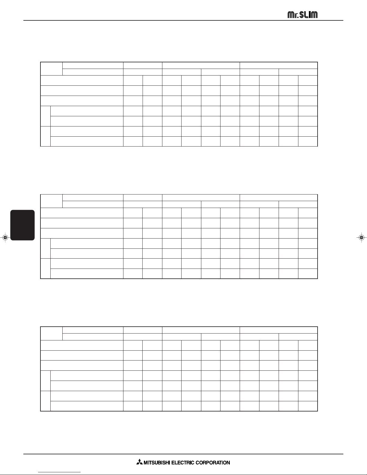
Cooling capacity correction factors
Models
5m 10m 15m 20m 25m 30m 35m 40m 45m 50m
P1 1.00 0.981 0.968 0.952 0.940 0.925 — — — —
P1.6 1.00 0.993 0.984 0.978 0.969 0.961 0.956 0.948 — —
P2 1.00 0.993 0.984 0.978 0.969 0.961 0.956 0.948 — —
Refrigerant piping length (one way)
Heating capacity correction factors
Models
5m 10m 15m 20m 25m 30m 35m 40m 45m 50m
P1 1.00 0.998 0.995 0.993 0.990 0.988 — — — —
P1.6 1.00 0.998 0.995 0.993 0.990 0.988 0.985 0.983 — —
P2 1.00 0.998 0.995 0.993 0.990 0.988 0.985 0.983 — —
Refrigerant piping length (one way)
Cooling performance curve (50Hz) Heating performance curve (50Hz)
CEILING
CASSETTE PM
PERFORMANCE DATA
A-297
Page 18

CEILING CASSETTE PM SERIES PMH-P1/P1.6/P2BA
UNIT
1.5m
MICROPHON
CEILING
Ambient temperature 27:
Test conditions are based on JIS Z8731
90
80
70
60
50
40
30
20
10
63 125 250 500 1000 2000 4000 8000
APPROXIMATE THRESHOLD OF
HEARING FOR CONTINUOUS
NOISE
NC-60
NC-50
NC-40
NC-30
NC-20
NC-70
OCTAVE BAND SOUND PRESSURE LEVEL, dB re 0.002 MICRO BAR
BAND CENTER FREQUENCIES, Hz
Hi
NOTCH
Mi1
Mi2
Lo
35
SPL(dB)
33
31
29
LINE
90
80
70
60
50
40
30
20
10
63 125 250 500 1000 2000 4000 8000
APPROXIMATE
THRESHOLD OF
HEARING FOR
CONTINUOUS
NOISE
NC-60
NC-50
NC-40
NC-30
NC-20
NC-70
OCTAVE BAND SOUND PRESSURE LEVEL, dB re 0.002 MICRO BAR
BAND CENTER FREQUENCIES, Hz
Hi
NOTCH
Mi1
Mi2
Lo
40
SPL(dB)
38
36
34
LINE
90
80
70
60
50
40
30
20
10
63 125 250 500 1000 2000 4000 8000
APPROXIMATE
THRESHOLD OF
HEARING FOR
CONTINUOUS
NOISE
NC-60
NC-50
NC-40
NC-30
NC-20
NC-70
OCTAVE BAND SOUND PRESSURE LEVEL, dB re 0.002 MICRO BAR
BAND CENTER FREQUENCIES, Hz
Hi
NOTCH
Mi1
Mi2
Lo
42
SPL(dB)
40
38
36
LINE
A.6.8 NOISE CRITERION CURVES
PMH-P1BA
CASSETTE PM
NOISE CRITERION CURVES
CEILING
PMH-P1.6BA PMH-P2BA
A-298
Page 19

CEILING CASSETTE PM SERIES
A.6.9 OUTLET AIR SPEED AND COVERAGE RANGE
MODEL Air flow (m3/min) Air speed (m/sec) Converage (m)
PMH-P1BA 8.4 3.7 5.9
PMH-P1.6BA 10.0 4.3 7.0
PMH-P2BA 11.0 4.7 7.7
CEILING
CASSETTE PM
OUTLET AIR SPEED AND COVERAGE RANGE
A-299
Page 20

CEILING CASSETTE PM SERIES Wired Remote Controller
PAR-20MAA
ON/OFF
CENTRALLY CONTROLLED
ERROR CODE
CLOCK
ON OFF
˚C
CHECK
CHECK MODE
FILTER
TEST RUN
FUNCTION
˚C
1Hr.
NOT AVAILABLE
STAND BY
DEFROST
FILTER
CHECK TEST
TEMP.
TIMER SET
Press this button to switch the cooler,
electronic dry (dehumidify), automatic
and heater modes.
OPERATION SWITCH button
This sets the room temperature. The
temperature setting can be performed
in 1: units
Setting range
Cooler 19: to 30:
Heater 17: to 28:
TEMP. ADJUSTMENT button
This switches between continuous
operation and the timer operation.
TIMER button
This switches between the operation
and stop modes each time it is pressed.
The lamp on this button lights during
operation.
ON/OFF button
Only press this button to perform an
inspection check or test operation.
Do not use it for normal operation.
CHECK-TEST RUN button
This switch the horizontal fan motion
ON and OFF.
(Not available for this model.)
LOUVER button
This adjusts the vertical angle of the
ventilation.
AIR DIRECTION button
This resets the filter service indication
display
FILTER button
This sets the current time, start time
and stop time.
TIME SETTING button
This sets the ventilation fan speed.
AIR SPEED button
A.6.10 REMOTE CONTROLLER
A.6.10.1 Wired Remote Controller
Once the controls are set, the same operation mode can be repeated by simply pressing the ON/OFF button.
● Operation buttons
CEILING
CASSETTE PM
REMOTE CONTROLLER
A-300
Page 21

PAR-20MAA
ON/OFF
CENTRALLY CONTROLLED
ERROR CODE
CLOCK
ON OFF
˚C
CHECK
CHECK MODE
FILTER
TEST RUN
FUNCTION
˚C
1Hr.
NOT AVAILABLE
STAND BY
DEFROST
FILTER
CHECK TEST
TEMP.
TIMER SET
POWER display
SET TEMPERATURE display
DEFROST display
CHECK display
STANDBY display
TIMER display
CENTRALLY
CONTROLLED display
CLOCK display
OPERATION MODE display
AIR DIRECTION display
AIR SPEED display
FILTER display
Operation lamp
ROOM TEMPERATURE display
display
This lamp lights when the filter need
to be cleaned.
This display lights in the check
mode or when a test operation is
performed.
This lamp lights during operation,
goes off when the unit stops and
flashes when a malfunction occurs.
The temperature of the suction air
is displayed during operation. The
display range is 8: to 39:. The
display flashes 8: when the actual
temperature is less than 8: and
flashes 39: when the actual temperature is greater than 39:.
This lamp lights when electricity is
supplied to the unit.
This displays the selected setting
temperature.
This indicates when the defrost operation is performed.
This indicates when a malfunction
has occurred in the unit which
should be checked.
The [STANDBY] symbol is only displayed from the time the heating operation starts unit the heated air begins to blow.
This indicates when the continuous
operation and time operation modes
are set.
It also display the time for the timer
operation at the same time as when
it is set.
This indicates when the unit is controlled by optional features such as
central control type remote controller.
The current time, start time and stop
time can be displayed in ten second intervals by pressing the time
switch button. The start time or stop
time is always displayed during the
timer operation.
This indicates the operation mode.
This displays the air direction.
The selected fan speed is displayed.
CHECK MODE
TEST RUN
● Display
CEILING CASSETTE PM SERIES Wired Remote Controller
In this display example on the bottom left, a condition
where all display lamps light is shown for explanation
purposes although this differs from actual operation.
CAUTION:
● Only the Power display lights when the unit is stopped and power supplied to the unit.
● When the central control remote control unit, which is sold separately, is used the ON-OFF button, operation switch button and TEMP.
adjustment button do not operate.
● “NOT AVAILABLE” is displayed when the Air speed button are pressed.This indicates that this room unit is not equipped with the fan
direction adjustment function and the louver function.
● When power is turned ON for the first time, it is normal that “H0” is displayed on the room temperature indication (For max. 2 minutes).
Please wait until this “H0” indication disappear then start the operation.
CEILING
CASSETTE PM
REMOTE CONTROLLER
A-301
Page 22

CEILING CASSETTE PM SERIES
A.6.11 TROUBLESHOOTING
Problem
Unit does not cool or heat very well.
The unit stops operating before
arriving at the set temperature in
the heating mode.
The air flow direction suddenly
changes.
A white mist is expelled from the
indoor unit.
The indicators of the remote controller do not light up when operated.
NOTE: After a power cut, the unit will not restart automatically. You will have to restart it by pressing the POWER - ON/OFF button on the remote
controller.
If none of the above apply, turn the main switch off and contact the dealer from whom you bought the air-conditioner, telling him the model name and the nature
of the problem. Do not try to fix the unit yourself.
Wired remote controllers
In any of the following cases, turn off the main power switch and contact your local dealer for service:
• The operation lamp (on the main unit) flashes.
CEILING
CASSETTE PM
TROUBLESHOOTING
• The switches do not work properly.
• The circuit breaker trips frequently (or the fuse blows frequently).
• Water has accidentally been splashed into the unit.
• Water leaks from the unit.
• Something is accidentally dropped into the air-conditioner.
• An unusual noise is heard during operation.
Wireless remote controllers: The Operating LED blinks.
Solution
Clean the filter.
Frost forms when the outdoor temperature is low and humidity is high. Wait
for about 10 minutes for the frost to melt.
After one hour of cooling-mode operation with the air flow in a downward direction, the unit will automatically
change to the “Horizontal air flow” mode.
When the unit is in the heating or defrosting mode, it will automatically
change to the “Horizontal air flow mode”.
This may occur just after the unit is
turned on when a high level of humidity is present in the room.
Turn on the power switch. “ · ” will be
displayed.
Problem
CENTRALLY CONTROLLED is displayed in the remote controller.
The start and stop functions are not available just after restarting the unit.
“H0” is displayed in the remote controller.
An error code is displayed in the remote
controller.
The operating display of the wireless remote controller’s receiver is flashing.
Solution
The start and stop functions of the remote controller are not available when
the CENTRALLY CONTROLLED message is lit.
Wait about three minutes (operation
has stopped to prevent damage to the
air conditioner).
An automatic startup test is being performed (will last for about two minutes).
A self-diagnostic function is being performed to preserve the air conditioner.
∗ Do not attempt to make repairs your-
self. Turn the main switch off and contact the dealer from whom you bought
the air conditioner. Provide him or her
with the name of the unit and the information displayed in the remote
controller.
The following do not indicate any malfunction:
Odours: smells such as tobacco or cosmetic odours may persist after they have been sucked into the unit.
Sound of liquid flowing inside indoor unit: this can occur during or after operation and is simply the sound of refrigerant being circulated inside the unit.
Ticking sound coming from indoor unit: this can occur when cooling or heating has just begun or has just stopped. It is caused by the indoor unit shrinking or
expanding slightly due to the change in temperature.
The message “CENTRALLY CONTROLLED” appearing on the LCD panel: from time to time, this message may come up on the LCD panel. This does not indicate
any malfunction.
A-302
Page 23

A
C
B
D
S1 S2 S3
S1
S2
S3
D
F
C
B
A A A
CEILING CASSETTE PM SERIES PMH-P1/P1.6/P2BA
C
A
D
AB
110
230
E
F
230
(C)
(B)
(A)
A
B
A.6.12 INSTALLATION PROCEDURE
PMH-P1/P1.6/P2BA
(mm)
1. Installing position
• The dimensions of ceiling opening can be regulated within the range
2. Refrigerant pipes
s Check that the difference between the heights of the indoor
Models
P1 max. 30 m max. 30 m max. of 9
P1.6, P2 max. 40 m max. 40 m max. of 12
• Height difference limitations are binding regardless of which unit,
shown in following diagram; so center the main unit against the opening of ceiling, ensuring that the respective opposite sides on all sides
of the clearance between them becomes identical.
A Air intake
B Air outlet
C Ceiling panel
D Min. 200 mm
E Suspension bolts W3/8 or M10
F Grille
and outdoor units, the length of refrigerant pipe, and the number
of bends in the pipe are within the limits shown below.
(A) Pipe length (B) Height (C) Number of
(one way) difference bends (one way)
indoor or outdoor, is positioned higher.
A Indoor unit
B Outdoor unit
CEILING
CASSETTE PM
For Power supply
For
Power
supply
3. Electrical work precaution
• The compressor will not operate unless the power supply phase
connection is correct.
• Grounding protection with a no-fuse breaker (earth leakage breaker
[ELB]) is usually installed for D.
• The connection wiring between the outdoor and indoor units can
be extended up to a maximum of 50 meters, and the total extension including the crossover wiring between rooms is a maximum
of 80 m.
Use flat cable (three core wires) for indoor and outdoor connection
wiring, and connect the core wires in their line-up order to S1, S2
and S3 of the outdoor unit’s terminal board.
A means for the disconnection of the supply with an isolation switch, or
similar device, in all active conductors shall be incorporated in the fixed
wiring.
A Indoor unit
B Outdoor unit
C Remote controller
D Main switch/fuse
F Grounding
Caution:
Do not push the contactor button (52C) on the outdoor unit, otherwise the compressor may be damaged.
A-303
INSTALLATION PROCEDURE
Page 24

CEILING CASSETTE PM SERIES PMH-P1/P1.6/P2BA
FE
D
C
I
C
H
A·B
G
D
B
M
L
K
D
E
D
H
I
G
D
F
F
F
Max. 20m
0.75–1.5m
N
O
A
B
C
Max. 15cm
Max. 50cm
F
CEILING
CASSETTE PM
INSTALLATION PROCEDURE
4. Refrigerant piping work
• This unit has the flared connections on both indoor and outdoor
sides.
1) When using commercially available copper pipes:
• When commercially available copper pipes are used, wrap liquid
and gas pipes with commercially available insulation materials (heatresistant to 100: or more, thickness of 12 mm or more).
• The indoor parts of the drain pipe should be wrapped with
polyethylene foam insulation materials (specific gravity of 0.03, thickness of 9 mm or more).
Refrigerant and Drainage Piping Sizes
Item
Refrigerant piping
Model
Liquid OD{6.35 (1/4") OD{9.52 (3/8")
Gas OD{12.7 (1/2") OD{15.88 (5/8")
Drainage piping PVC pipe: OD{26 (1")
2) Installing procedures
1. Remove the flare nuts and caps from the indoor unit.
2. Flare-cut the liquid and gas pipes then apply refrigerating machine
oil (to be locally procured) over the flare-cut seat surface.
3. Quickly connect the refrigerant piping.
∗ Remember to tighten the flare nuts with a double spanner.
4. Slide the supplied pipe cover 3 over the gas piping until it is pressed
against the sheet metal inside the unit.
5. Slide the provided pipe cover 3 over the liquid piping until it is
pressed against the sheet metal inside the unit.
6. Tighten the pipe cover 3 at the both ends (15 - 20 mm) with the
supplied bands 4.
A Gas piping E Turn the seam upward.
B Liquid piping F Press the pipe cover against the sheet metal.
C Band 4 G Refrigerant piping heat insulating material
D Pipe cover 3 H Wrap tightly
P1 P1.6, P2
I Cut off excess length of band.
A-304
5. Drain piping work
• Use O. D. { 26 PVC PIPE for drain piping and provide 1/100 or
more downward slope.
• Be sure to connect the piping joints using adhesive of polyvinyl chloride family.
• Observe the figure for piping work.
• Use attached drain hose to change the pipe extraction direction.
1 Correct piping
2 Wrong piping
A Insulation (9 mm or more)
B Downward slope (1/100 or more)
C Support metal
K Air bleeder
L Raised
M Odor trap
N Make as little as possible
O Make as great as possible (approx. 10 cm)
Grouped piping
D VP20 (O. D. {26 PVC PIPE)
E Make it as large as possible
F Indoor unit
G Make the piping size large for grouped piping.
H Downward slope (1/100 or more)
I O. D. {38 PVC PIPE for grouped piping.
(9 mm or more insulation)
Page 25

CEILING CASSETTE PM SERIES PMH-P1/P1.6/P2BA
H
A
C
D
G
F
E
B
I
A
B
F
C
D
F
E
In cases of upward drainage
• The largest dimension possible for the vertical section at B is
60 cm from the lower surface of the ceiling. Make this vertical section as short as possible.
Water drainage check
1. Fill the drainage pan with about 0.5 liters of water. (Don’t pour water
directly into the drain pump.)
2. Make a test run of the unit (in Cooling mode).
3. Check for water drainage at the transparent check window and the
outlet of the drainage pipe.
4. Stop the test run. (Don’t forget to turn off the power.)
A Ceiling panel
B Max. 60 cm
C Position of drain outlet
D Make as short as possible (Max. 15 cm)
E Make as small as possible
F Downward slope (1/100 or more)
G Make as great as possible (Min. 10 cm)
H Drainage pipe vertical section
I Water bottle (procure locally)
6. Electric work
* Make sure all electrical wiring is complete before installing the cover
panel.
1. Remove the cover from the address board (two bolts).
2. Remove the cover from the electrical box (one bolt).
3. Remove the bolts securing the electrical box and lower the box (two
bolts).
4. Insert the wires into the electrical box.
5. Connect the wires securely to the terminal block.
* Be sure to make the various wires long enough so the box may be
lowered from the unit during servicing.
6. Secure the wires with the wiring clamp on the side of the electrical
box.
7. Replace the parts you have removed to their original locations.
A Cover
B Electrical box
C Indoor/outdoor unit connecting terminal
D Remote controller terminals
E Control board
F Secure with the wiring clamp
A means for the disconnection of the supply with an isolation switch, or
similar device, in all active conductors shall be incorporated in the fixed
wiring.
CEILING
CASSETTE PM
INSTALLATION PROCEDURE
A-305
Page 26

CEILING CASSETTE PM SERIES PMH-P1/P1.6/P2BA
C
F
G
E
D
A
B
C
D
E
2
2
3
2
2
2
2
A
D
B
AD
C
A
B
123
Fig. 1
Fig. 2
Fig. 3
CEILING
CASSETTE PM
INSTALLATION PROCEDURE
Fig. 4
Fig. 5
A-306
7. Installing the grille
1) Checking the contents
• This kit contains this manual and the following parts.
Accessory name Q’ty Remark
1 Grille 1
2 Screw 6 M5 × 0.8 × 16
3 Screw 1 4 × 16
A Points for securing the grille
B Points for securing the grille
C Indoor unit
D Ceiling surface
E Drainage pan
F Places for securing front grille
G Make sure these surfaces are flush with each other (0-3 mm).
2) Checks before setting in place
• Before installing the front panel, make sure the indoor unit is square
with the ceiling opening (or parallel to the angle between the wall
and the ceiling).
• Check that the four points where the front panel will be secured are
in contact with the ceiling surface (see figs. 1, 2).
• Check that the insulation for the refrigerant pipes, drainage pipes,
etc. is in place and that wiring connections and arrangements are
complete.
3) Installing the grille
• Open the intake grille by pressing on the place marked Push, and
remove the air filter.
• Remove the screw cover in the middle of the blower.
• Open the upper and lower flaps on the indoor unit completely.
• Hook the temporary holding tabs on the front panel to the hooks on
the indoor unit (see figs. 3, 4).
A Hooks
B Open the upper and lower flaps completely
C Temporary holding tab
D Temporary holding tab
E Screw cover
• Adjust the front panel so that it fits properly in the angle between the
ceiling and the wall, and install the securing bolts 2 (supplied with
this grille) in their four places at left and right, leaving them slightly
loose.
• Next tighten the securing bolts 2 and securing screws 3 in the
center three places.
• Finally tighten the securing bolts 2 in the four places at left and right.
• At this point, make sure there are no gaps between the indoor unit
and the front panel, and between the front panel and the ceiling
surface. If there are gaps, the wind may come in and it may cause
water to drip (see fig. 5).
* Tighten the securing bolts 2 and securing screws 3 completely.
• Replace the air filter and screw cover, and press the intake grille on
the place marked Push until you hear it snap into place.
A Hook
D Temporary securing tabs
4) Checks after installing
• Check that there are no gaps between the indoor unit and the front
panel, and between the front panel and the ceiling surface. If there
are gaps, the wind may come in and condensation may result.
• Check that the air filter is in place.
A Ceiling surface
B Indoor unit
C Grille
D No gaps here
Page 27

CEILING CASSETTE PM SERIES PMH-P1/P1.6/P2BA
A.6.13 ACCESSORIES AND PARTS
PMH-P1/P1.6/P2BA
1 2
3
5
The indoor unit should be supplied with the following spare parts and
accessories (contained in the inside of the intake grille).
Part number Accessory Quantity
1 Washer (without insulation) 4
2 Washer (with insulation) 4
3 Pipe cover 2
4 Band 4
5 Screw
6 Remote controller 1
4
6
4
M5o0.8o30
CEILING
CASSETTE PM
ACCESSORIES AND PARTS
A-307
Page 28

CEILING CASSETTE PM SERIES
0.53A ± 15%
A.6.14 SAFETY DEVICE SETTINGS
PMH-P1/P1.6/P2BA
Safety device
Fan motor
protector
Thermal fuse
Heater thermal
switch
CEILING
CASSETTE PM
Model
The motor has over current protective function. When current peak of starting and over load arrives at 0.53A±15%
the function operates.
PMH-P1BA PMH-P1.6BA PMH-P2BA
—
—
SAFETY DEVICE SETTINGS
A-308
Page 29

Main Sub
1
2
3
Main
(00)
Outdoor unit; (00)...Refrigerant address
(SW1; 3~6)
Indoor unit; (00)–w
Indoor unit number
(auto setting)
Refrigerant address
(receiving from the
outdoor unit)
(00)-1 (00)-2 (00)-3
Sub
1
222
3
Outdoor unit; (00~02)...Refrigerant address
(SW1; 3~6)
Indoor unit; (00~02)–w
Indoor unit number
(auto setting)
Refrigerant address
(receiving from the
outdoor unit)
Main
(00)
(00)-1 (00)-2 (01)-1
1
(01)
1
(02)
1
222
(02)-1 (02)-2
2
3
333
CEILING CASSETTE PM SERIES PMH-P·BA
A.6.15 SYSTEM CONTROL
PMH-P·BA
VARIETY OF SYSTEM CONTROL FUNCTIONS
(1) System construction
A-control model which just wires the connecting line between the indoor and outdoor unit and supply the power is applicable
to any models of standard (1:1), twin and triple.
System construction
Remote controller
Indoor unit
Outdoor unit
Various setting
Remarks
Standard 1:1
1 Unit (indoor/outdoor) power supply L/N
2 Connecting line between the indoor and
outdoor; S1/S2/S3, Polarized 3-wire
3 Remote controller transmission line; Non
polarezed 2-wire
Remote control main/sub setting necessity
(In case of 2 remote controllers)
No setting
No setting
Synchronized twin. Triple
1 Unit (indoor/outdoor) power supply L1/L2/L3/N
2 Connecting line between the indoor and
outdoor; S1/S2/S3, Polarized 3-wire
3 Remote controller transmission line; Non
polarezed 2-wire
Remote control main/sub setting necessity
(In case of 2 remote controllers)
No setting (initial setting)
No setting (initial setting)
(1) Indoor unit number is set automatically
Group control
CEILING
CASSETTE PM
System construction
1 Unit (indoor/outdoor) power supply L1/L2/L3/N
2 Connecting line between the indoor and outdoor; S1/S2/S3, Polarized 3-wire
3 Remote controller transmission line; Non polarezed 2-wire
Remote controller
Indoor unit
Outdoor unit
Various setting
Remarks
Remote control main/sub setting necessity
(In case of 2 remote controllers)
No setting (initial setting)
Refrigerant address setting; SW1; 3~6
(1) Indoor unit number is set automatically
(2) When the refrigerant address of the unit is “00”, Remote controller is supplied.
SYSTEM CONTROL
A-309
Page 30

CEILING CASSETTE PM SERIES
CEILING
CASSETTE PM
SYSTEM CONTROL
A-310
 Loading...