

Page 1
TECHNICAL & SERVICE MANUAL
CONTENTS
1.
TYPES OF CONNECTED OUTDOOR UNITS
····2
2. SAFETY FOR USE··········································3
3. PART NAMES AND FUNCTIONS ··················5
4. DATA ·······························································6
5. OUTLINES AND DIMENSIONS······················7
6. WIRING DIAGRAM·········································8
7. REFRIGERANT SYSTEM DIAGRAM·············9
8. TROUBLE SHOOTING·································10
9. SERVICE DATA (PARTS NAME)··················11
10. OPTIONAL PARTS ·······································14
[Model names]
PU-8YAKD
PU-10YAKD
PU-12YAKD
SPLIT-TYPE, AIR CONDITIONERS
2007
Page 2

2
1 TYPES OF CONNECTED OUTDOOR UNITS
Service manual No.
HWE07060
HWE07060
HWE07060
Model name
Outdoor unit
Indoor unit
PU - 8YAKD
PU - 10YAKD
PU - 12YAKD
PE - 8GAK(T)
PE - 16GAK(T)
PE - 10GAK(T)
PE - 20GAK(T)
PE - 12GAK(T)
PU-8YAKD.TH-BS
PU-10YAKD.TH-BS
PU-12YAKD.TH-BS
PU-8YAKD.TH
PU-10YAKD.TH
PU-12YAKD.TH
Standard Model Salt tolerant
Salt tolerant
Outdoor Unit List
PU-8YAKD
PU-10YAKD
PU-12YAKD
Model name
Specification
PU-8YAKD.TH-BS-T
PU-10YAKD.TH-BS-T
PU-12YAKD.TH-BS-T
PU-8YAKD.TH-T
PU-10YAKD.TH-T
PU-12YAKD.TH-T
Standard Model
PU-8YAKD
PU-10YAKD
PU-12YAKD
Model name
Specification
Page 3
3
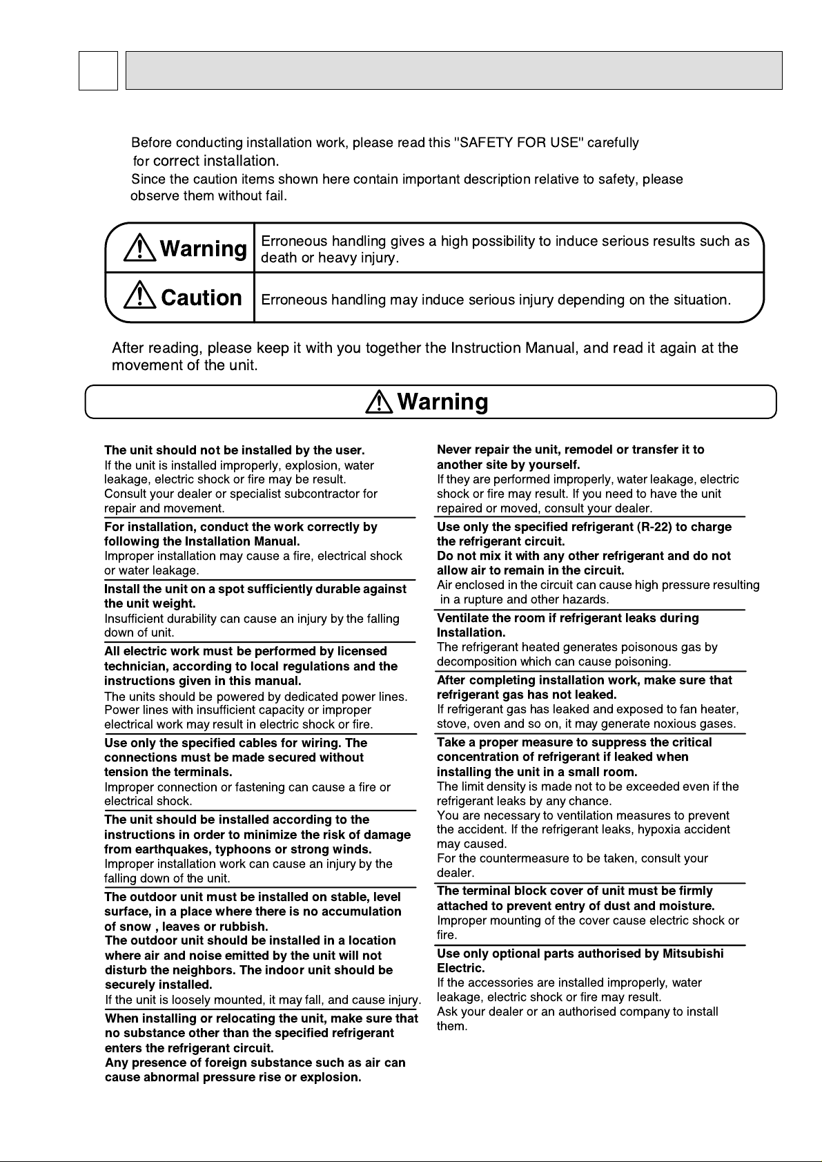
2 SAFETY FOR USE
Before conducting installation work, please read this ''SAFETY FOR USE'' carefully
for
correct installation.
Since the caution items shown here contain important description relative to safety, please
observe them without fail.
After reading, please keep it with you together the Instruction Manual, and read it again at the
movement of the unit.
The unit should not be installed by the user.
If the unit is installed improperly, explosion, water
leakage, electric shock or fire may be result.
Consult your dealer or specialist subcontractor for
repair and movement.
For installation, conduct the work correctly by
following the Installation Manual.
Improper installation may cause a fire, electrical shock
or water leakage.
Install the unit on a spot sufficiently durable against
the unit weight.
Insufficient durability can cause an injury by the falling
down of unit.
All electric work must be performed by licensed
technician, according to local regulations and the
instructions given in this manual.
The units should be powered by dedicated power lines.
Power lines with insufficient capacity or improper
electrical work may result in electric shock or fire.
Use only the specified cables for wiring. The
connections must be made secured without
tension the terminals.
Improper connection or fastening can cause a fire or
electrical shock.
The unit should be installed according to the
instructions in order to minimize the risk of damage
from earthquakes, typhoons or strong winds.
Improper installation work can cause an injury by the
falling down of the unit.
The outdoor unit must be installed on stable, level
surface, in a place where there is no accumulation
of snow , leaves or rubbish.
The outdoor unit should be installed in a location
where air and noise emitted by the unit will not
disturb the neighbors. The indoor unit should be
securely installed.
When installing or relocating the unit, make sure that
no substance other than the specified refrigerant
enters the refrigerant circuit.
Any presence of foreign substance such as air can
cause abnormal pressure rise or explosion.
If the unit is loosely mounted, it may fall, and cause injury.
Never repair the unit, remodel or transfer it to
another site by yourself.
If they are performed improperly, water leakage, electric
shock or fire may result. If you need to have the unit
repaired or moved, consult your dealer.
Use only the specified refrigerant (R-22) to charge
the refrigerant circuit.
Do not mix it with any other refrigerant and do not
allow air to remain in the circuit.
Air enclosed in the circuit can cause high pressure resulting
in a rupture and other hazards.
Ventilate the room if refrigerant leaks during
Installation.
The refrigerant heated generates poisonous gas by
decomposition which can cause poisoning.
After completing installation work, make sure that
refrigerant gas has not leaked.
If refrigerant gas has leaked and exposed to fan heater,
stove, oven and so on, it may generate noxious gases.
Take a proper measure to suppress the critical
concentration of refrigerant if leaked when
installing the unit in a small room.
The limit density is made not to be exceeded even if the
refrigerant leaks by any chance.
You are necessary to ventilation measures to prevent
the accident. If the refrigerant leaks, hypoxia accident
may caused.
For the countermeasure to be taken, consult your
dealer.
The terminal block cover of unit must be firmly
attached to prevent entry of dust and moisture.
Improper mounting of the cover cause electric shock or
fire.
Use only optional parts authorised by Mitsubishi
Electric.
If the accessories are installed improperly, water
leakage, electric shock or fire may result.
Ask your dealer or an authorised company to install
them.
Erroneous handling gives a high possibility to induce serious results such as
death or heavy injury.
Erroneous handling may induce serious injury depending on the situation.
Warning
Warning
Caution
Page 4
4
Caution
Never install on the place where a combustible gas
might leak.
The gas may ignite or explode when the gas leaks and
collects in surrounding of the unit.
When the unit is installed at telecommunication
centers or hospitals, take a proper provision
against noise.
The erroneous operation of air conditioner may be
induced by inverter equipment, independent power
device, medical equipment or communication
equipment.
While the erroneous operation of medical equipment or
communication equipment may caused by the air
conditioner.
For special use as for foods, animals/plants,
precision equipment or art objects, the applicability
should be confirmed beforehand.
As the use for the applications other than that
designed originally may result in the deterioration of the
quality. Consult your dealer in this regard.
Do not use the unit under a special atmosphere.
Installing the unit at the following places may cause a
trouble, a place where much machine oil, salt sonnet,
humidity or dust, spa district, a place full of sulfur gas,
volatile gas, or corrosive gas, a place near high
frequency processing machine.
Thermal insulation of the drain pipes is necessary
prevent dew condensation.
If the drain pipes are not properly insulated,
condensation will result and drip on ceiling, floor or other
possessions.
The drain piping must process by surely,and insulate
the drain piping not to be dewy.
When the room humidity exceeds 80% or when the
drain pipe is clogged, water may drip from the indoor
unit. The outdoor unit produces condensation during the
heating operation.
Make sure to provide drainage around the outdoor unit if
such condensation is likely to cause damage.
Install drain piping according to this Installation
Manual to ensure proper drainage.
Place thermal insulation on the pipes to prevent
condensation.
Improper drain piping may cause water leakage and
damage to furniture or other possessions.
The unit must be properly earth connected.
Do not connect the earth wire to gas pipe, city water
pipe, lightning rod or telephone earth wire.
Improper earth connection may cause electrical shock.
When installing at a watery place, provide an
electric leak breaker.
Failure to mount the electric leak breaker may cause
electrical shock.
Use breaker or fuse with proper capacity.
Make sure that there is a main power switch.
Using a wire or a copper wire instead of proper capacity
of fuse can cause fire or trouble.
Other appliances connected to the same line could cause
an overload.
For the power lines, use standard cables of
sufficient current capacity.
Otherwise, current leakage, overheating or fire may
occur.
When installing the power lines, do not apply
tension to the cables.
The tighten or loosen the connections may cause generate
heat and cause fire.
Remote controller is not pushed with the thing
sharpening ahead.
It occasionally causes the electric shock and the
breakdown.
Arrange the configuration of wiring not to bring up
the panel and terminal cover, and fasten the panel
and terminal cover securely.
The poor mounting of the panel or terminal cover may
cause the heat generation of the terminal connection,
a fire or electrical shock.
Do not wash the unit with water.
If washed with water, electrical shock may be caused.
Do not handle the switch with wet hands.
Otherwise electrical shock can be resulted.
Be very careful on handling the unit.
When carrying in outdoor unit, be sure to support it at
four points.
Carrying in and lifting with 3-point support may make
outdoor unit unstable, resulting in a fall of it.
The unit should not be carried by only one person if it is
more than 20kg.
Some units use PP bands for packing.
Do not use any PP band for delivery purpose.
Do not touch the heat exchanger fins with your bear
hands.
Doing so may cut your hands.
Be sure to safely dispose the packaging materials.
Packaging materials, such as catches and other metal
or wooden parts, may cause stabs or other injuries.
Tear off and discard plastic packing bags so that
children will not play any of them.
If children play with a plastic bag which was not torn off,
it may cause a risk of suffocation.
Do not leave the mounting base being damaged.
The damaged base may cause the falling down of
the unit which may give injury.
Turn on the main power switch more than 6 hours
before starting operation.
Do not turn the main power switch OFF during seasons
of heavy use, doing so can result in failure.
Do not touch the compressor or refrigerant piping
without wearing glove on your hands.
Touching directly such part can cause a burn or
frostbite as it becomes high or low temperature
according to the refrigerant state.
Do not touch the metal edges inside the unit
without wearing glove on your hands.
Touching directly it may injure your hands.
Do not remove the panel or the fan guard from
the outdoor unit when it is running.
You could be injured if you touch rotating, hot or highvoltage parts.
Do not operate the air conditioner without the air
filter set place.
Dust may accumulate, and cause a failure.
At emergency (if you smell something burning), stop
operation and turn the power source switch off.
Continuing the operation without eliminating the
emergency state may cause a machine trouble, fire, or
electrical shock.
After stopping operation, be sure to wait for five
minutes before turning off the main power switch.
Otherwise, water leakage or unit failure may occur.
Remote controller is not installed for the place
where direct sunshine strikes.
Do not connect the unit in the reverse phase
sequence.
If connected in the reverse phase sequence, the fan
on the outdoor unit will turn in the wrong direction and
makes the compressor rattle, and it will result in compressor
damage.
Page 5
5
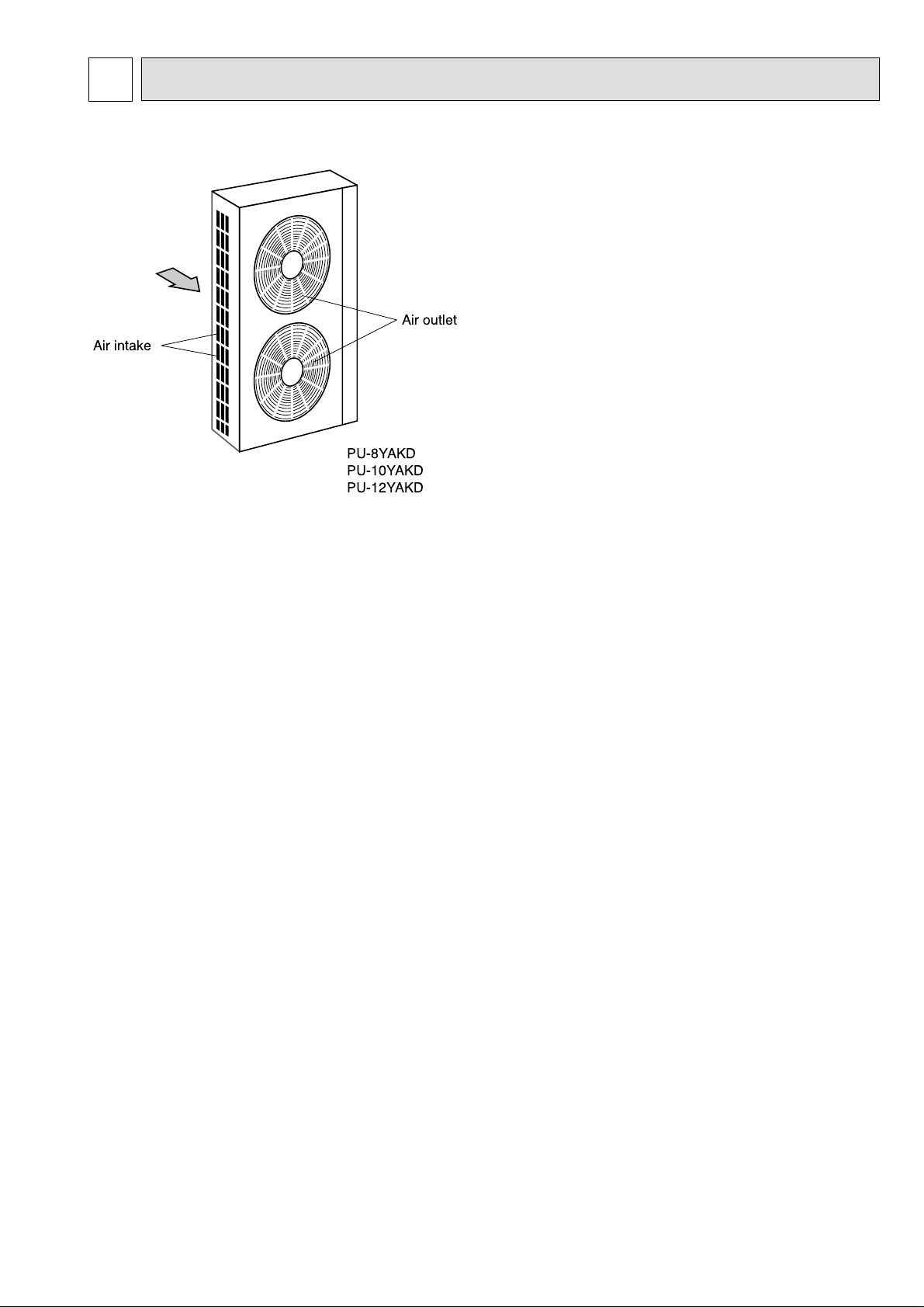
3 PART NAMES AND FUNCTIONS
✻Unit of pressure is based on ISO (International Standardization Organization)
[kgf/cm
2
]➝[MPa] (1MPa=10.2kgf/cm2)
●Outdoor Unit
PU-8YAKD
PU-10YAKD
PU-12YAKD
Air outlet
Air intake
Page 6

6
4-2. COMPRESSOR TECHNICAL DATA
PU-8 PU-10 PU-12
at 25
˚C
Outdoor Unit
Compressor Model
Widing
Resistance
(
Ω)
ZR-94KC-TFD-501
1.59
1.59
1.59
T1-T2
T2-T3
T3-T1
ZR-125KC-TFD-501
1.23
1.23
1.23
ZR-144KC-TFD-501
1.227
1.227
1.227
4 DATA
4-1. ELECTRICAL SPECIFICATIONS
Rating conditions
• JIS B 8616
Indoor : 27˚C(80˚F)D.B.,19˚C(66˚F)W.B.
Outdoor : 35˚C(95˚F)D.B.,24˚C(75˚F)W.B.
PU-8YAKD PU-10YAKD
3N~ 380/400/415V 50Hz
PU-12YAKD
Model name
Power supply
Current
Input
Starting current
A
A
kW
12.4
6.43
95
16.0
9.00
125
17.9
10.32
118
4-3. REFILLING REFRIGERANT CHARGE (R-22 : kg)
4-4. SOUND DATA
Model
7.5m 10m 15m 20m 25m 30m 35m 40m 45m 50m
PU-8
PU-10
PU-12
0.0
0.0
0.0
0.2
0.2
0.2
0.5
0.5
0.5
0.9
0.9
0.9
1.2
1.2
1.2
1.6
1.6
1.6
1.9
1.9
1.9
2.3
2.3
2.3
2.6
2.6
2.6
3.0
3.0
3.0
Piping length (one way) Additional refriferant charge (R22)áááákg
Warning
● If there is an insufficient amount of refrigerant in the system, the unit will behave in one of the following ways: 1) the discharge
temperature of the unit rises abnormally high, which is detected as an error, and the unit comes to a stop; 2) the discharge
temperature of the compressor rises abnormally high, the unit goes into the unload operation, which appears as the P8 error
on the display, and the unit comes to a stop; or 3) the built-in thermostat on the compressor goes off and stops the compressor. In either case, replenish and adjust the refrigerant. Once the unit goes into the unload operation, it will take a long
time until normal operation can be restored.
● It takes at least 3 hours for the compressor to recover after an unload operation.
Outdoor units
Outdoor unit
Position measurement
Measurement
point
Sound Levels
0.75m
1m
SPL
dB(A)
PU-8,10,12
Model
PU-8
PU-10
PU-12
66
66
66
63Hz
72
69
68
125Hz
68
66
65
250Hz
64
64
63
500Hz
64
63
64
1000Hz
62
62
61
2000Hz
58
56
57
4000Hz
53
54
53
8000Hz
44
50
45
OCTAVE BAND FREQ.Hz
Page 7

7
5 OUTLINES AND DIMENSIONS
PU-8,10,12YAKD
Unit : mm
< Accessory >
· Conduit mouting plate
(Painted the same color as the unit body)
a)
ø27 ············································· 1pc.
b)
ø34 ············································· 1pc.
· Tapping screw 4X12 ·························· 4pcs.
· Connection pipe ································· 1pc.
· Packing ·············································· 1pc.
Note 1. It is possible to change to
ø27 or ø34 by
selecting the conduit mounting plate a,b.
4-10X20 Holes
Refrigerant pipe
PU-8YAKD
:ø25.4 (1 flange)
PU-10,12YAKD
:
ø28.6 (1-1/8 flange)
Knock out hole
Pressure gauge
(For option)
Refrigerant pipe
ø15.88(5/8 flare)
<For the indoor unit
connection wiring>
ø27 Hole
Note 1
<For the power
supply wiring>
ø40 Hole
<For mounting
anchor bolt M8>
[Field supply]
Air outlet
Air
inlet
Air inlet
Top view
Right side view
Front view
Left side view
Connection pipe
(Accessory)
615
3454734
585 1515
1480
1047
108.5 830 108.5
15
62
97
152 55
65
115 100
Page 8

8
6 WIRING DIAGRAM
PU-8,10,12YAKD
3
1
C13
OUTDOOR UNIT
CZ
2
TB2
1
52C30Z
CZ
30Z
51C
C17
63L
1
2
2
1
C14
63H
CH
52C
51C
52C
3
2
1
3
2
C21
1
C11
MF3
MF2
MC
F03
N
L3
L2
POWER SUPPLY
3N~PE
380/400/415V
50HZ
TB1
L1
RED
WHITE
BLACK
BLUE
GREEN/YELLOW
L2
L1
L3
N
L1
1
2
3
4
5
6
78
GRAY
VIOLET
VIOLET
ORANGE
ORANGE
BLUE
INDOOR UNIT
(*1)
(*1)
PE
CIRCUIT BREAKER
(FIELD SUPPLY)
PU-8YAKD : 30A
PU-10YAKD : 40A
PU-12YAKD : 60A
PE
OUTDOOR UNIT
Note:1.The dotted lines show field wiring.
2.Color of earth wire is yellow and green twisting.
3.Specification subject to change without notice.
4.This motor(*1) includes auto reset type internal thermostat.
AUXILIARY RELAY
5. mark is connector. mark is terminal.
FUSE (3.15A 250VAC)
CRANK CASE HEATER (COMPRESSOR)CH
PRESSURE SWITCH (HIGH PRESSURE)
PRESSURE SWITCH (LOW PRESSURE)
63H
63L
TERMINAL BLOCKTB1,2
30Z,CZ
F03
OVER CURRENT RELAY (COMPRESSOR)51C
MAGNETIC CONTACTOR (COMPRESSOR,FAN MOTOR)52C
SYMBOL NAME
MC
MF2,3
COMPRESSOR MOTOR
FAN MOTOR (OUTDOOR)
Caution,
1.To protect compressor from abnormal current,over current relays is installed.
Therefore, do not change factory set value of over current relays.
Page 9

9
7 REFRIGERANT SYSTEM DIAGRAM
PU-8YAKD
PU-10YAKD
Indoor heat
exchanger
Outdoor heat
exchanger
Indoor coil
thermistor
TH2
Brazing
Flange
connection
Refrigerant pipe ø15.88
(With heat insulator)
Flow of refrigerant
Flow of refrigerant
Compressor
Accumulator
Ball Valve
Low pressure
switch
High pressure
switch
Ball Valve
Capillary tube
8HP : O.D. 6.0 X I.D. 4.0X L1000
10HP : O.D. 6.0 X I.D. 7.0 X L700
Strainer
Refrigerant pipe
8HP: ø25.4
10HP:ø28.6
(With heat insulator)
Serviceport
(With service port and strainer)
Serviceport
( )
Indoor heat
exchanger
Outdoor heat
exchanger
Indoor coil
thermistor
TH2
Brazing
Flange
connection
Refrigerant pipe ø15.88
(With heat insulator)
Compressor
Accumulator
Ball Valve
Low pressure
switch
High pressure
switch
Ball Valve
Capillary tube
Capillary tube
(O.D. 6.0 X I.D. 7.0 X L700)
(O.D. 6.0 X I.D. 4.0 X L800)
Capillary tube
(O.D. 6.0 X I.D. 4.0 X L700)
Strainer
Refrigerant pipe
ø28.6
(With heat insulator)
Serviceport Serviceport
(With service port and strainer)
Flared
connection
Flared
connection
PU-12YAKD
Page 10

10
8
TROUBLE SHOOTING
8-1. SELF-DIAGNOSTIC FUNCTION
8-2. HOW TO CHECK THE PARTS
8-2-1. Simple parts check method
Check
code
Diagnosis of malfunction Cause Check points
(P4) Abnormality of drain sensor 1) Bad contact of transmission
wire
2) Damaged thermistor
1) Check the connector.
2) Measure the resistance of the thermistor
4 ~
5.
As for the normal resistance, refer to the case
of P1.
If the resistance is normal, replace the indoor con-
troller board.
(P5) Malfunction of drain pump 1) Malfunction of drain pump
2) Damaged drain sensor
1) Check the drain pump.
2)
● Check the drain sensor.
● Check the drain sensor heater. Normal resis-
tance should be 82Ω.
If the resistance is normal, replace the indoor con-
troller board.
(P6) Coil frost protection is work-
ing.
1) Short cycle of air cycle
2) Dirty air filter
3) Damaged fan
4) Abnormal refrigerant
1) Clear obstructions from the air cycle.
2) Clean the air filter
3) Check the fan.
4) Check the refrigerant temperature.
(P8) Abnormality in outdoor unit 1) Wrong wiring of indoor/outdoor
connecting wire
2) Reversed phase
✻
3) Protection device is working
4) Damaged outdoor coil thermistor
1) Check the indoor/outdoor connecting wire.
2) Change the connection of electric wiring.
3) Check the protection device.
4) Measure the resistance of the outdoor coil thermistor. If the resistance is normal, replace the
outdoor controller board.
(P1)
(P2)
Abnormality of room temperature thermistor (TH1)
Abnormality of indoor coil
thermistor (TH2)
1) Bad contact of thermistor
2) Damaged thermistor
1) Check the thermistor.
2) Measure the resistance of the thermistor.
Normal resistance should be as follows.
0°C···15kΩ 30°C ····4.3kΩ
10°C·····9.6kΩ 40°C·····3.0kΩ
20°C·····6.3kΩ
If the resistance is normal, replace the indoor
controller board.
✻Warning
To avoid damage to the compressor, make certain that all three phases of the power supply voltage are in the proper phase
sequence.The fan on the outdoor unit that is connected in the reverse phase sequence will turn in the wrong direction and
make the compressor rattle.Once the built-in thermostat is triggered, it will take a long time until it returns to its pre-set temperature. Until the built-in thermal switch closes, the compressor cannot be started, even after the phase sequence is corrected.
¥ Outdoor units
Part name
Fan motor
Thermal protector
trip temperature
150±5ûC : ON
90±14ûC: OFF
Judgment instructions
Measure the resistance value across the terminals with a multimeter. (Winding
temperature 20 ûC)
White
Black
Normal
26
Ω
Abnormal
Open or short
Motor lead wire
Between 2 phases
Red
Page 11

11
9
SERVICE DATA (PARTS NAME)
PU-8,10YAKD
Detailed View of Section A
A
Pressure switch
63L
Pressure switch
63H
Crankcase
heater
Compressor
Heat exchanger
Heat exchanger
Accumulator
Capillary tube
Ball valve
Ball valve
Service port
Page 12

12
PU-12YAKD
A
Detailed View of Section A
Pressure switch
63L
Pressure switch
63H
Crankcase
heater
Compressor
Heat exchanger
Heat exchanger
Accumulator
Capillary tube
Capillary tube
for cooling
Ball valve
Service port
Ball valve
Capillary tube
Page 13

13
CONTROL BOX
Power source terminal block
Fuse F03
Magnetic contactor
for compressor (52C)
Relay(30Z)
Relay(CZ)
Terminal block for outdoor / indoor
control wiring connection
Page 14

1
2
14
10 OPTIONAL PARTS
Item Individual order number
Outlet grill PAC-SG208SG-E
Pressure gauge
Remark
2 pcs / pack
1 pcs / packPAC-SK209PG-E
Page 15

15
Page 16

New publication, effective July 2007.
Specifications subject to change without notice.
HWE07070
Printed in Japan
 Loading...