

Mitsubishi PRH-P400, PRH-500MYA OPERATION MANUAL
Air-Conditioners
ROOFTOP UNIT
PRH-P400, 500MYA
FOR INSTALLER
FÜR INSTALLATEURE
POUR L’INSTALLATEUR
PARA EL INSTALADOR
PER L’INSTALLATORE
VOOR DE INSTALLATEUR
FÖR INSTALLATÖREN
PARA O INSTALADOR
INSTALLATION MANUAL
For safe and correct use, please read this operation manual thoroughly before operating the air-conditioner unit.
INSTALLATIONSHANDBUCH
Zum sicheren und ordnungsgemäßen Gebrauch der Klimageräte das Installationshandbuch gründlich durchlesen.
GB
D
F
E
I
MANUEL D’INSTALLATION
Veuillez lire le manuel d’installation en entier avant d’installer ce climatiseur pour éviter tout accident et vous assurer d’une utilisation
correcte.
MANUAL DE INSTALACIÓN
Para un uso seguro y correcto, lea detalladamente este manual de instalación antes de montar la unidad de aire acondicionado.
MANUALE DI INSTALLAZIONE
Per un uso sicuro e corretto, leggere attentamente questo manuale di installazione prima di installare il condizionatore d’aria.
INSTALLATIEHANDLEIDING
Voor een veilig en juist gebruik moet u deze installatiehandleiding grondig doorlezen voordat u de airconditioner installeert.
INSTALLATIONSMANUAL
Läs denna installationsmanual noga för säkert och korrekt bruk innan luftkonditioneringen installeras.
MANUAL DE INSTALAÇÃO
Para segurança e utilização correctas, leia atentamente este manual de instalação antes de instalar a unidade de ar condicionado.
NL
SW
P
3
[Fig. 3.1.1]
GB
D
(1)
(3)
250
450
450
<A> <B>
L
2
L
3
L
A
1
315
<B>(2)<A>
(4)
C
450
*
45
300
A
900
B
<C>
A
L
3
L
1
L
2
900
A
hH
hH
670
670
hH
A
B
<A> Top view
<B> Front view
<C> Side view
A Front
B Must be open
C Wall height (H)
L1: 450 L2: 450 L3: 250
F
NL
SWI
E
4
5
[Fig. 4.0.1]
[Fig. 5.1.1]
40°
14 m
14 m
B
15
55
2200
[Fig. 5.1.3]
B
A
A M10 anchor bolt procured at the site.
B Corner is not seated.
2130952170
P
[Fig. 5.1.2]
2
A
ø50.8
ø25.4
155
611
B
A
A Stander
800
2000
B
800
144
A Bottom wiring through hole
B (bolt hole)
55
6
[Fig.6.0.1]
B
A Drain piping
B
23
89
1549
E
70
C
F
A
D
B Socket R1
C Drain trap
D The drain pipe should extend below the level.
>
2 × External static pressure
E
=
>
F
2 × E
=
7
[Fig.7.0.1]
<A>
B
[Fig.7.0.2]
56
44 4413 × 150 Pitch = 1950
A
C
24 - ø3 Holes
(1312)
A
(2038)
B
F
A
D
E
568 × 150 Pitch = 1200
38 - ø3 Holes
B
A
10(434)
2 × 150 Pitch = 300
10
6767
10
4 × 150 Pitch = 600
(730)
F
A
<B>
E
H
I
G
500
A
<A> Ex. Side flow
<B> Ex. Top flow
A Duct
B Roof curb
C Single duct divider
D Plenum divider
E Insulator
F Keep duct-work length 850 mm or more
G Rainproof the part where the duct flange is screwed on (Top
flow only).
H Canvas duct (Keep 500 mm or more for canvas duct space)
I Top panel
GB
D
B
<A>
293 1312 525
A
F
43420273080
46 2038 46
B
10
6565
<B>
293 1312 525
249 434
A
NL
B
SWI
[Fig.7.1.1]
A
A Fresh air inlet (on both sides)
A
[Fig.7.1.2]
73080
46 2038 46
<A> In case of side flow
<B> In case of top flow
A Outlet duct flange
B Inlet duct flange
7.1
E
B
A Filter (Field supply)
B Fresh air inlet duct (Field supply)
P
3
30
46
30
30120
83.5
C
A
B
D
8
[Fig.8.1.1]
(1)
8.1
8.2
[Fig.8.2.1]
A
GB
D
F
A Remote controller profile
B Required clearances surrounding
the remote controller
C Temperature sensor
D Installation pitch
(2)
<A> For installation in the switch box: <B> For direct installation on the wall
D
C
E
F
H
C Wall D Conduit
E Lock nut F Bushing
G Switch box H Remote controller cord
I Seal with putty.
(3)
<A> For installation in the switch box <B> For direct installation on the wall
C
I
G
D
select one of the following:
E
B-1.
B-2.
I
I
D
H
A To TB5 on the unit
B Terminal block TB6 in remote controller
No polarity
[Fig.8.3.1]
(1) (2)
[Fig.8.3.2]
8.3
AB
B
TB6
NL
SWI
E
P
9
G
C Switch box for two pieces D Remote controller cord
E Cross-recessed, pan-head screw
G Seal the remote controller cord service entrance with putty
H Wood screw
[Fig. 9.0.1]
(1) Normal Connecting
BC
A
A Power supply
B Earth leakage breaker
C Wiring circuit breaker or isolating switch
D Remote controller
E Address
PRH-P400, 500
L1 L2 L3 N
(2) Grouping (8 units)
D
BCA
B
A
B
A
C
C
PRH-P400, 500
E
(0, 1)
L1 L2 L3 N
·
·
·
·
·
PRH-P400, 500
E
(12, 13)
L1 L2 L3 N
PRH-P400, 500
E
(14, 15)
L1 L2 L3 N
D
4

9
9.1
[Fig. 9.1.1]
[Fig. 9.2.1]
B
0
8
OFF ON
1
2
3
4
5
6
OFF ON
1
2
3
4
5
6
1
9
OFF ON
1
2
3
4
5
6
OFF ON
1
2
3
4
5
6
9.2
C
ø52
C
ø40
C
D
A When installing conduct from bottom panel
B When installing conduct from front panel
C Mounting plate (attached)
D Knock-out hole
ø40
ø50.8
A
OFF ON
1
2
3
2
4
5
6
OFF ON
1
2
3
10
4
5
6
OFF ON
1
2
3
3
4
5
6
OFF ON
1
2
3
11
4
5
6
10
OFF ON
1
2
3
4
4
5
6
OFF ON
1
2
3
12
4
5
6
[Fig. 10.0.1]
OFF ON
1
2
3
5
4
5
6
OFF ON
1
2
3
13
4
5
6
OFF ON
1
2
3
6
4
5
6
OFF ON
1
2
3
14
4
5
6
OFF ON
1
2
3
7
4
5
6
OFF ON
1
2
3
15
4
5
6
[Fig. 10.0.2]
K
K
K
A
A=0.016xC(mm)
A
GB
C
K
K
<A>
<B>
D
<A> Parallel degree of pulley
<B> Belt tension
A Flexion load (W)
11
C
12
[Fig. 11.0.1]
FB
[Fig.12.2.1]
F
STEP 1 STEP 2
A
A
E
C
B
STEP 3
NL
SWI
D
E
2
P
A
B
D
A Top panel B Cover (outer side) C Flange D Panel E Fan F Cover (inner side)···2pcs
14
[Fig.14.1.1]
AEFD
2
TB5 TB5 TB5
1
BC
A Unit
B Main remote controller
C Subordinate remote controller
D Refrigerant address = 00, 01
E Refrigerant address = 02, 03
F Refrigerant address = 04, 05
<SW4>
OFF
1
2
12.2
ON
C
D
A Stop
B Cooling
C Operation
D Heating
AA
5
Contents
1. Safety precautions ...................................................................................... 6
1.1. Before installation and electric work .......................................... 6
1.2. Precautions for devices that use R407C refrigerant .................. 6
1.3. Before getting installed .............................................................. 7
1.4. Before getting installed (moved) - electrical work ...................... 7
1.5. Before starting the test run ........................................................ 7
2. Unit accessories ......................................................................................... 7
3. Selecting an installation site ....................................................................... 7
3.1. Space required around unit ....................................................... 7
4. Lifting method and weight of product .......................................................... 8
5. Installation of unit ........................................................................................ 8
5.1. Installation ................................................................................. 8
6. Drain piping work ........................................................................................ 8
7. Duct work .................................................................................................... 8
7.1. Fresh air inlet, duct installations, and operating restrictions ...... 9
8. Remote controller ....................................................................................... 9
8.1. Installing procedures ................................................................. 9
8.2. Connecting procedures ............................................................. 9
1. Safety precautions
GB
1.1. Before installation and electric work
s Before installing the unit, make sure you read all the “Safety
precautions”.
s The “Safety precautions” provide very important points re-
D
F
NL
SWI
garding safety. Make sure you follow them.
Symbols used in the text
Warning:
Describes precautions that should be observed to prevent danger of injury
or death to the user.
Caution:
Describes precautions that should be observed to prevent damage to the
unit.
Symbols put on the unit
: Indicates an action that must be avoided.
: Indicates that important instructions must be followed.
: Indicates a part which must be grounded.
: Indicates that caution should be taken with rotating parts. (This symbol is
displayed on the main unit label.) <Color: yellow>
: Beware of electric shock. (This symbol is displayed on the main unit label.)
<Color: yellow>
Warning:
Carefully read the labels affixed to the main unit.
8.3. Fitting the upper case ................................................................ 9
8.4. Function selection ................................................................... 10
9. Electrical wiring ......................................................................................... 13
9.1. Address settings ...................................................................... 14
9.2. Wiring connection .................................................................... 14
10. Specifications for installing the belt ........................................................... 14
11. Modification method of fan direction (From side flow to top flow).............. 14
12. Test run ...................................................................................................... 15
12.1. Before test run ......................................................................... 15
12.2. Test run procedures................................................................. 15
12.3. Self-check ................................................................................ 16
12.4. Remote controller check .......................................................... 17
13. Troubleshooting ......................................................................................... 18
13.1. How to handle problems with the test run ............................... 18
13.2. The following occurrences are not problems or errors ............ 19
14. System control .......................................................................................... 19
14.1. System settings ....................................................................... 19
14.2. Examples of refrigerant system address setting ..................... 20
14.3. Capacity control setting method (PRH-P400, 500MYA only) .. 20
• Have all electric work done by a licensed electrician according to “Electric Facility Engineering Standard” and “Interior Wire Regulations” and
the instructions given in this manual and always use a special circuit.
- If the power source capacity is inadequate or electric work is performed im-
properly, electric shock and fire may result.
• Securely install the unit terminal cover (panel).
- If the terminal cover (panel) is not installed properly, dust or water may enter
the unit and fire or electric shock may result.
• When re-charging the refrigerant circuit after installation or relocation of
the unit, only use the specified refrigerant (R407).
- If a different refrigerant or air is mixed with the original refrigerant, the refrig-
erant cycle may malfunction and the unit may be damaged.
• When moving and reinstalling the air conditioner, consult the dealer or
an authorized technician.
- If the air conditioner is installed improperly, water leakage, electric shock, or
fire may result.
• Do not reconstruct or change the settings of the protection devices.
- If the pressure switch, thermal switch, or other protection device is shorted
and operated forcibly, or parts other than those specified by Mitsubishi Electric are used, fire or explosion may result.
• Do not step on the unit.
- Step on the unit may deform top panel and result in injury.
• To dispose of this product, consult your dealer.
• The installer and system specialist shall secure safety against leakage
according to local regulation or standards.
- Following standards may be applicable if local regulation are not available.
• Pay a special attention to the place, such as a basement, etc. where refrigeration gas can stay, since refrigeration is heavier than the air.
• The appliance is not intended for use by young children or infirm persons without supervision.
• Young children should be supervised to ensure that they do not play
with the appliance.
Warning:
• Ask the dealer or an authorized technician to install the air conditioner.
- Improper installation by the user may result in water leakage, electric shock,
or fire.
• Install the unit at a place that can withstand its weight.
- Inadequate strength may cause the unit to fall down, resulting in injuries.
• Use the specified cables for wiring. Make the connections securely so
that the outside force of the cable is not applied to the terminals.
- Inadequate connection and fastening may generate heat and cause a fire.
E
• Prepare for strong winds and earthquakes and install the unit at the specified place.
- Improper installation may cause the unit to topple and result in injury.
• Always use other accessories specified by Mitsubishi Electric.
- Ask an authorized technician to install the accessories. Improper installation
by the user may result in water leakage, electric shock, or fire.
• Never repair the unit. If the air conditioner must be repaired, consult the
P
dealer.
- If the unit is repaired improperly, water leakage, electric shock, or fire may
result.
• Do not touch the heat exchanger fins.
- Improper handling may result in injury.
• When handling this product, always wear protective equipment.
EG: Gloves, full arm protection namely boiler suit, and safety glasses.
- Improper handling may result in injury.
• Install the air conditioner according to this Installation Manual.
-
If the unit is installed improperly, water leakage, electric shock, or fire may result.
6
1.2. Precautions for devices that use R407C
refrigerant
Caution:
• Use liquid refrigerant to fill the system.
- If gas refrigerant is used to seal the system, the composition of the refrigerant in the cylinder will change and performance may drop.
• Do not use a refrigerant other than R407C.
- If another refrigerant (R22, etc.) is used, the chlorine in the refrigerant may
cause the refrigerator oil to deteriorate.
• Use a vacuum pump with a reverse flow check valve.
- The vacuum pump oil may flow back into the refrigerant cycle and cause the
refrigerator oil to deteriorate.
• Do not use the following tools that are used with conventional refrigerants.
(Gauge manifold, charge hose, gas leak detector, reverse flow check valve,
refrigerant charge base, refrigerant recovery equipment)
- If the conventional refrigerant and refrigerator oil are mixed in the R407C,
the refrigerant may deteriorated.
- If water is mixed in the R407C, the refrigerator oil may deteriorate.
- Since R407C does not contain any chlorine, gas leak detectors for conven-
tional refrigerants will not react to it.
• Do not use a charging cylinder.
- Using a charging cylinder may cause the refrigerant to deteriorate.
• Be especially careful when managing the tools.
- If dust, dirt, or water gets in the refrigerant cycle, the refrigerant may deteriorate.
1.3. Before getting installed
Caution:
• Do not install the unit where combustible gas may leak.
- If the gas leaks and accumulates around the unit, an explosion may result.
• Do not use the air conditioner where food, pets, plants, precision instruments, or artwork are kept.
- The quality of the food, etc. may deteriorate.
• Do not use the air conditioner in special environments.
- Oil, steam, sulfuric smoke, etc. can significantly reduce the performance of
the air conditioner or damage its parts.
• When installing the unit in a hospital, communication station, or similar
place, provide sufficient protection against noise.
- The inverter equipment, private power generator, high-frequency medical
equipment, or radio communication equipment may cause the air conditioner
to operate erroneously, or fail to operate. On the other hand, the air conditioner may affect such equipment by creating noise that disturbs medical
treatment or image broadcasting.
• Do not install the unit on a structure that may cause leakage.
- When the room humidity exceeds 80 % or when the drain pipe is clogged,
condensation may drip from the indoor unit. Perform collective drainage work
together with the outdoor unit, as required.
1.4. Before getting installed (moved) - elec-
trical work
Caution:
• Ground the unit.
- Do not connect the ground wire to gas or water pipes, lightning rods, or
telephone ground lines. Improper grounding may result in electric shock.
• The reverse phase of L lines (L
but the reverse phase of L lines and N line can be not be detected.
- The some electric parts should be damaged when power is supplied under
the miss wiring.
• Install the power cable so that tension is not applied to the cable.
- Tension may cause the cable to break and generate heat and cause a fire.
• Install an earth leakage circuit breaker, as required.
- If an earth leakage circuit breaker is not installed, electric shock may result.
• Use power line cables of sufficient current carrying capacity and rating.
- Cables that are too small may leak, generate heat, and cause a fire.
• Use only a circuit breaker and fuse of the specified capacity.
- A fuse or circuit breaker of a larger capacity or a steel or copper wire may
result in a general unit failure or fire.
1, L2, L3) can be detected (Error cord: 4103),
• Do not wash the air conditioner units.
- Washing them may cause an electric shock.
• Be careful that the installation base is not damaged by long use.
- If the damage is left uncorrected, the unit may fall and cause personal injury
or property damage.
• Install the drain piping according to this Installation Manual to ensure
proper drainage. Wrap thermal insulation around the pipes to prevent
condensation.
- Improper drain piping may cause water leakage and damage to furniture
and other possessions.
• Be very careful about product transportation.
- Only one person should not carry the product if it weighs more than 20 kg.
- Some products use PP bands for packaging. Do not use any PP bands for a
means of transportation. It is dangerous.
- Do not touch the heat exchanger fins. Doing so may cut your fingers.
- When transporting the outdoor unit, suspend it at the specified positions on
the unit base. Also support the outdoor unit at four points so that it cannot
slip sideways.
• Safely dispose of the packing materials.
- Packing materials, such as nails and other metal or wooden parts, may cause
stabs or other injuries.
- Tear apart and throw away plastic packaging bags so that children will not
play with them. If children play with a plastic bag which was not torn apart,
they face the risk of suffocation.
1.5. Before starting the test run
Caution:
• Turn on the power at least 12 hours before starting operation.
- Starting operation immediately after turning on the main power switch can
result in severe damage to internal parts. Keep the power switch turned on
during the operational season.
• Do not touch the switches with wet fingers.
- Touching a switch with wet fingers can cause electric shock.
• Do not touch the refrigerant pipes during and immediately after operation.
- During and immediately after operation, the refrigerant pipes are may be hot
and may be cold, depending on the condition of the refrigerant flowing through
the refrigerant piping, compressor, and other refrigerant cycle parts. Your
hands may suffer burns or frostbite if you touch the refrigerant pipes.
• Do not operate the air conditioner with the panels and guards removed.
- Rotating, hot, or high-voltage parts can cause injuries.
GB
D
F
2. Unit accessories
1 Conduit mounting plate × 2 2 Tapping screw M4 × 4 3 Remote controller
3. Selecting an installation site
• Select a site with sturdy fixed surface sufficiently durable against the weight of
unit.
• Before installing unit, the routing to carry in unit to the installation site should
be determined.
• Select a site where the unit is not affected by entering air.
• Select a site where the flow of supply and return air is not blocked.
• Select a site which allows the supply air to be distributed fully in room.
• Do not install unit at a site with oil splashing or steam in much quantity.
• Do not install unit at a site where combustible gas may generate, flow in, stagnate or leak.
• Do not install unit at a site where equipment generating high frequency waves
(a high frequency wave welder for example) is provided.
• Do not install unit at a site where fire detecter is located at the supply air side.
(Fire detector may operate erroneously due to the heated air supplied during
heating operation.)
• When special chemical product may scatter around such as site chemical plants
and hospitals, full investigation is required before installing unit. (The plastic
components may be damaged depending on the chemical product applied.)
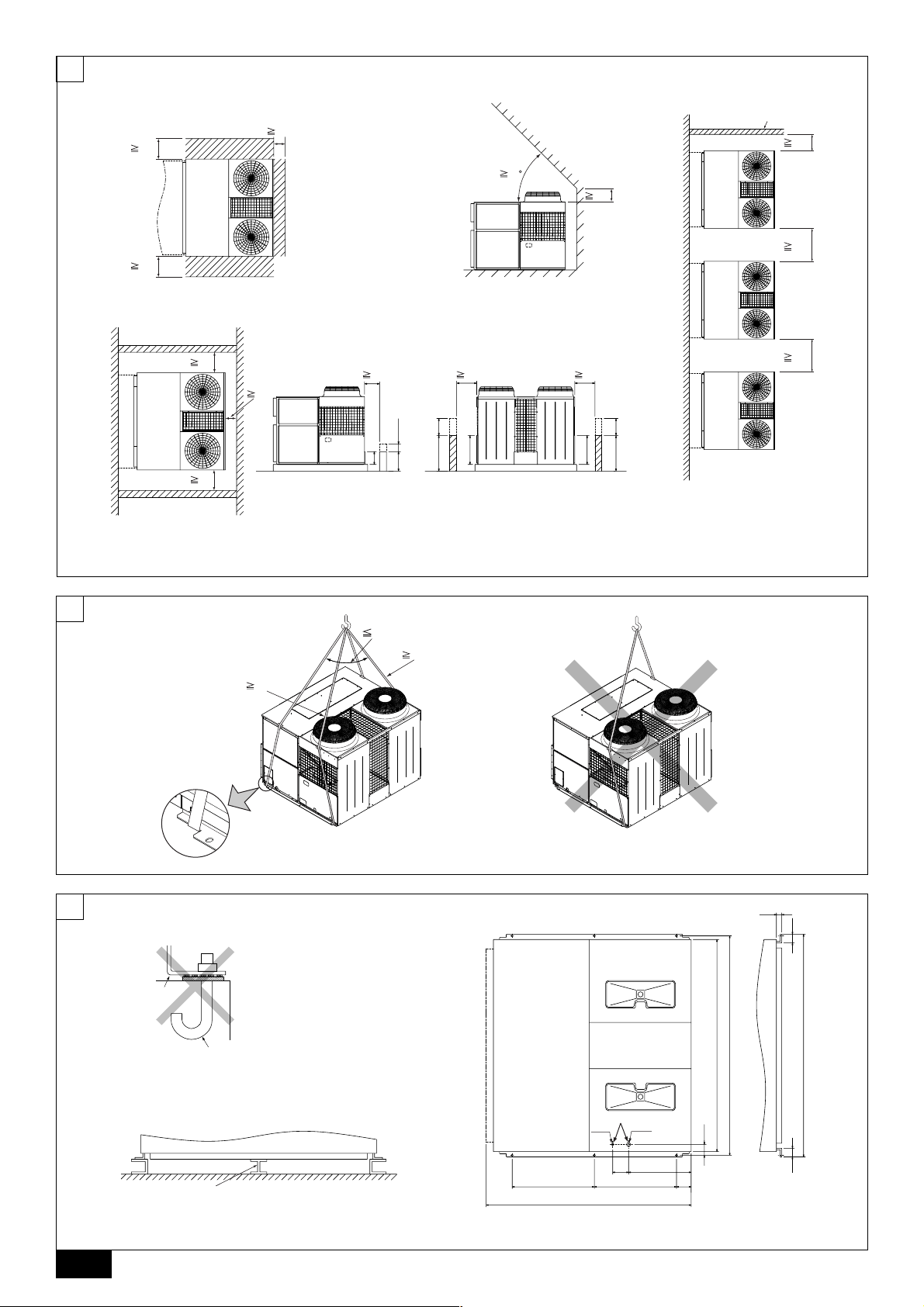
3.1. Space required around unit
[Fig. 3.1.1] (P.2)
<A> Top view <B> Front view
<C> Side view
A Front B Must be open
C Wall height (H)
L1: 450 L2: 450 L3: 250
(1) Basic space required
A space of at least 250 mm is necessary at the right side for inlet air. Taking servicing, etc. from the right side into account, a space of about 450 mm should be
provided, the same as at the front and back.
(2) When there is an obstruction above the unit
(3) When unit is surrounded by walls
Note:
• Wall heights (H) of the front and the back sides shall be within overall
height of unit panel.
• If the panel height is exceeded, add the “h” dimension of the Fig. 3.1.1 to
L
Example: When h is 100,
(4) Continuous installation
• Space required for continuous installation:
When installing several units, leave the space between each unit considering
passage for air and people.
• Open in the two directions.
• In case wall height (H) exceeds overall height of unit, add “h” dimension (h =
wall height <H> – overall height of unit) to * marked dimension.
1, L2 and L3.
L1: 450 L2: 450 L3: 250
the L
1 dimension becomes 450 + 100 = 550 mm.
NL
SWI
E
P
7
4. Lifting method and weight of product
[Fig. 4.0.1] (P.2)
Caution:
• Be very careful to carry product.
- Do not have only one person to carry product if it is more than 20 kg.
- PP bands are used to pack some products. Do not use them as a mean for transportation because they are dangerous.
- Do not touch heat exchanger fins with your bare hands. Otherwise you may get a cut in your hands.
- Tear plastic packaging bag and scrap it so that children cannot play with it. Otherwise plastic packaging bag may suffocate children to death.
- When carrying in outdoor unit, be sure to support it at four points. Carrying in and lifting with 3-point support may make outdoor unit unstable, resulting in a fall of it.
• Protect the corners on the unit that come in contact with the sling with padding.
5. Installation of unit
5.1. Installation
[Fig. 5.1.1] (P.2)
A M10 anchor bolt procured at the site. B Corner is not seated.
• Fix unit tightly with bolts so that unit will not fall down due to earthquake or
gust.
• Use concrete or angle for foundation of unit.
• Vibration may be transmitted to the installation section and noise and vibration
GB
may be generated from the floor and walls, depending on the installation conditions. Therefore, provide ample vibrationproofing (cushion pads, cushion
frame, etc.).
• Be sure that the corners are firmly seated. If the corners are not firmly seated,
the installation feet may be bent.
[Fig. 5.1.2] (P.2)
D
A Stander
• When making foundation of unit, put a stander in the middle of unit base.
6. Drain piping work
F
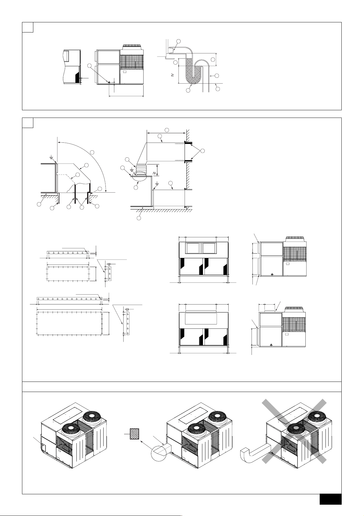
[Fig. 6.0.1] (P.3)
A Drain piping B Socket R1
C Drain trap
D The drain pipe should extend below this level.
>
E
2 × External static pressure
=
>
F
2 × E
=
NL
Warning:
• Be sure to install unit in a place strong enough to withstand its weight.
Any lack of strength may cause unit to fall down, resulting in a personal
injury.
• Have installation work in order to protect against a strong wind and earthquake.
Any installation deficiency may cause unit to fall down, resulting in a
personal injury.
When building the foundation, give full attention to the floor strength, drain water
disposal <during operation, drain water flows out of the unit>, and wiring routes.
Down wiring precautions
When down wiring are performed, be sure that foundation and base work does not
block the base through holes.
[Fig. 5.1.3] (P.2)
A Bottom wiring through hole B (bolt hole)
1. The condensate drain socket (R1) is provided. The drain pipe is connected to
the drain socket.
2. The drain pipe must be provided with a trap on the outside of the unit and also
installed at an incline for proper drainage, as shown [Fig. 6.0.1] (P.3).
3. To prevent dew condensation and leakage, provide drain pipes with insulation.
4. Upon completion of the piping work, check that there is no leakage and that
the water drains off properly.
7. Duct work
1. In case of side flow unit (factory setting) is equipped with horizontal supply and
return air openings. Duct connection to the unit should be made with duct
SWI
flanges and secured directly to the air openings with flexible duct connectors
to avoid normal noise transmission.
2. For vertical air supply, a field supply plenum should be used.
The figure below shows the recommended method for duct connection.
3. In case of top flow unit (modified when installed) is equipped with vertical supply and horizontal return air openings. Duct connection to the unit should be
made with duct flanges and securely attached to the air openings with flexible
duct connectors.
Since the sirocco fan cannot be replace without remove the top panel in top
flow position, a maintenance space to remove the top panel is required. For
that, canvas duct must be constructed between duct flange and duct.
4. To prevent air leakage, all duct seams should be taped.
E
Ducts run in air spaces that are not air-conditioned must be insulated and
provided with a vapor barrier.
Ducts exposed to the outside must be weather proofed.
For quiet operation, we recommend that the insulation on the supply duct be
placed inside, lining the duct.
5. Where ducts from the outside enter a building, the duct openings in the building should be sealed with weather stripping to prevent rain, dust, sand, etc.
P
from entering the building.
6. Fans will not accept any external resistance to airflow and what provision is
available if ductwork is to be fitted to the external fans.
7. Correctly sized filters must be fitted and there is no provision within the unit,
however the filters (field supply) may be installed in the return air.
8. Duct earth wiring must be connected to the earth point of unit (
[Fig. 7.0.1] (P.3)
<A> Ex. Side flow
<B> Ex. Top flow
A Duct B Roof curb
C Single duct divider D Plenum divider
E Insulator
F Keep duct-work length 850 mm or more
G Rainproof the part where the duct flange is screwed on (Top flow only).
H Canvas duct (Keep 500 mm or more for canvas duct space)
I Top panel
Caution:
• Do not step on the unit.
- Step on the unit may deform top panel and result in injury.
• Outlet duct is 850 mm or more necessary to construct.
• To connect the air conditioner main body and the duct for potential equalization.
• In case of top flow unit, keep 500 mm or more for canvas duct space.
Mount holes for outlet duct flange and inlet duct.
[Fig. 7.0.2] (P.3)
<A> In case of side flow
<B> In case of top flow
A Outlet duct flange B Inlet duct flange
mark point).
8
7.1. Fresh air inlet, duct installations, and
operating restrictions
This unit has an fresh air inlet on each side of the unit. Use the one that suits a
particular application.
[Fig. 7.1.1] (P.3)
A Fresh air inlet (on both sides)
Caution:
11
1 Properly seal duct connections.
11
22
2 Install a proper size filter at the opening of the inlet, and clean the filter
22
on a regular basis.
8. Remote controller
33
3 Install a duct longer than 850 mm or block the opening of the inlet with a
33
wire net to keep hands out of the inlet.
44
4 The opening of the connected duct must not be facing up as rain or snow
44
will enter the duct.
55
5 Be sure that the temperature of the mixed air (return air and outside air)
55
falls within the following ranges:
In the case of cooling operation: mixed air temperature 15
(30 - 80% RH)
In the case of heating operation: mixed air temperature 15
66
6 Install a reverse air-flow prevention plate inside return and supply ducts
66
to prevent the back flow of air during unit stoppage.
[Fig. 7.1.2] (P.3)
A Filter (Field supply)
B Fresh air inlet duct (Field supply)
°CWB - 24 °CWB
°CDB - 32 °CDB
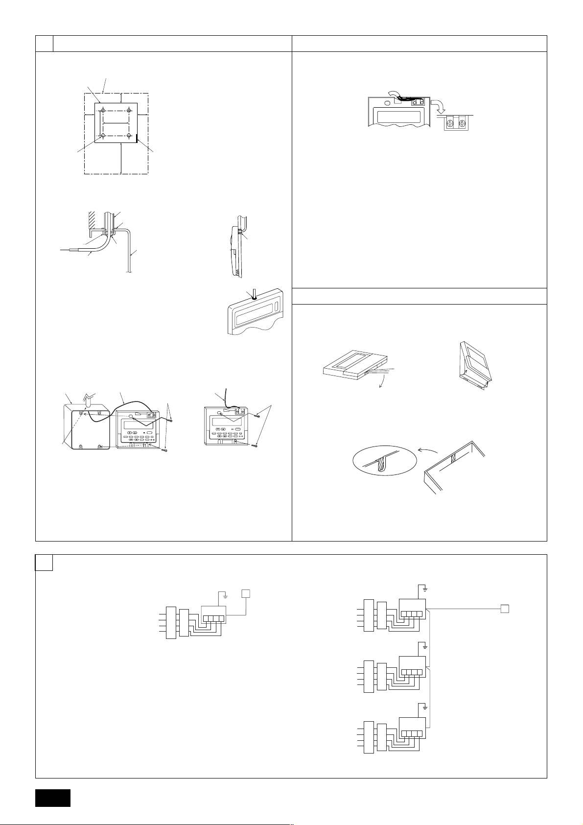
8.1. Installing procedures
(1) Select an installing position for the remote controller (switch box).
Be sure to observe the following precautions.
[Fig. 8.1.1.(1)] (P.4)
A Remote controller profile
B Required clearances surrounding the remote controller
C Temperature sensor D Installation pitch
1 The temperature sensors are located on both remote controller and unit. To
use the temperature sensor on the remote controller, mainly use the remote
controller for temperature setting or room temperature detection. Install the
remote controller in such an area that can detect average room temperatures,
free of direct sunlight, airflow from the air conditioner, and other such heating
source.
2 In either case when the remote controller is installed in the switch box or on the
wall, provide the clearances indicated in the diagram.
Note:
Check that there is no electric wire left close to the remote controller sensor.
If any electric wire is near the sensor, the remote controller may fail to detect
a correct room temperature.
3 Procure the following parts locally:
Switch box for two pieces
Thin copper conduit tube
Lock nuts and bushings
(2) Seal the service entrance for the remote controller cord with putty to
prevent possible invasion of dew drops, water, cockroaches or worms.
<A> For installation in the switch box:
• When the remote controller is installed in the switch box, seal the junction
between the switch box and the conduit tube with putty.
<B> For direct installation on the wall select one of the following:
B-1. To lead the remote controller cord from the back of the controller:
• Prepare a hole through the wall to pass the remote controller cord (in order to
run the remote controller cord from the back), then seal the hole with putty.
B-2. To run the remote controller cord through the upper portion:
• Run the remote controller cord through the cut-out upper case, then seal the
cut-out notch with putty similarly as above.
[Fig. 8.1.1.(2)] (P.4)
C Wall D Conduit E Lock nut
F Bushing G Switch box
H Remote controller cord I Seal with putty
(3) Install the lower case in the switch box or on the wall.
[Fig. 8.1.1.(3)] (P.4)
<A> For installation in the switch box
C Switch box for two pieces D Remote controller cord
E Cross-recessed, pan-head screw
G Seal the remote controller cord service entrance with putty
<B> For direct installation on the wall
H Wood screw
Caution:
Do not over-tighten the screws to possible deformed or broken lower case.
Note:
• Select a flat place for installation.
• Be sure to use two or more locations for securing of the remote controller in the switch box or on the wall.
8.2. Connecting procedures
• The remote controller cord can be extended up to a maximum of 200 m. Use
electric wires or (two-core) cables of 0.3 mm
tion of remote controller. Do not use multi-conductor cables to prevent possible malfunction of the unit.
(1) Connect the remote controller cord to the terminal block at the lower
case.
[Fig. 8.2.1] (P.4)
A To TB5 on the unit
B Terminal block TB6 in remote controller
No polarity
Caution:
• Do not use crimp-style terminals for connection to the remote controller
terminal block to eliminate contact with the boards and resultant trouble.
• Prevent remote cord chips from getting into the remote controller. Electric shock or malfunction may result.
2
to 1.25 mm2 for making connec-
8.3. Fitting the upper case
[Fig. 8.3.1] (P.4)
(1) To remove the upper case, put a slotted screwdriver tip in the latches as
shown in the diagram then move the screwdriver in the direction of arrow.
(2) To install the upper case, put the upper latches (at two locations) first,
then fit the upper case into the lower case as illustrated.
[Fig. 8.3.2] (P.4)
Note:
Wiring hole for installing directly on the wall (or open wiring)
• Cut off the shaded area from the upper case using a knife, nippers, etc.
• Take out the remote control cord connected to the terminal block via this
portion.
Caution:
• Do not move the screwdriver while inserting the tip far into the latches to
prevent broken latches.
• Be sure to put the upper case securely in the latches by pressing it until
a snap sounds. Loosely inserted, the upper case may fall down.
Note:
The operating section is covered with a protective sheet. Before using the
unit, remember to remove the protective sheet.
GB
D
F
NL
SWI
E
P
9
8.4. Function selection
PAR-21MAA
ON/OFF
FILTER
CHECK
OPERATION
CLEAR
TEST
TEMP.
MENU
BACK DAY
MONITOR/SET
CLOCK
ON/OFF
F
G
C
D
B
I
A
H
E
<Wired remote controller type>
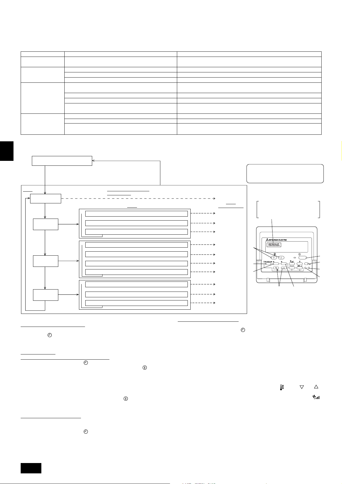
(1) Function selection of remote controller
The setting of the following remote controller functions can be changed using the remote controller function selection mode. Change the setting when needed.
Item 1
1.Change Language
Language setting to display
Item 2
• Display in multiple languages is possible.
(“CHANGE LANGUAGE”)
2.Function limit
(“FUNCTION
SELECTION”)
3.Mode selection
(“MODE SELECTION”)
(1)
Operation function limit setting (operation lock) (“LOCKING FUNCTION”)
(2) Use of automatic mode setting (“SELECT AUTO MODE”)
(3) Temperature range limit setting (“LIMIT TEMP FUNCTION”)
(1) Remote controller main/sub setting (“CONTROLLER MAIN/SUB”)
(2) Use of clock setting (“CLOCK”)
(3) Timer function setting (“WEEKLY TIMER”)
(4) Contact number setting for error situation (“CALL.”)
• Setting the range of operation limit (operation lock)
• Setting the use or non-use of “automatic” operation mode
• Setting the temperature adjustable range (maximum, minimum)
• Selecting main or sub remote controller
*
When two remote controllers are connected to one group, one controller must be set to sub.
• Setting the use or non-use of clock function
• Setting the timer type
• Contact number display in case of error
• Setting the telephone number
4.Display change
(“DISP MODE SETTING”)
(1) Temperature display °C/°F setting (“TEMP MODE °C/°F”)
(2)
Suction air temperature display setting (“ROOM TEMP DISP SELECT”)
(3)
Automatic cooling/heating display setting (“AUTO MODE DISP C/H”)
• Setting the temperature unit (°C or °F) to display
• Setting the use or non-use of the display of indoor (suction) air temperature
• Setting the use or non-use of the display of “Cooling” or “Heating” display during
operation with automatic mode
[Function selection flowchart]
[1] Stop the air conditioner to start remote controller function selection mode. → [2] Select from item1. → [3] Select from item2. → [4] Make the setting. (Details
are specified in item3) → [5] Setting completed. → [6] Change the display to the normal one. (End)
GB
D
F
NL
SWI
Normal display (Display when the
air condition is not running)
(Hold down the E button and press the D button for two
seconds.)
* The display cannot be changed during the unit function
selection, the test run and the self diagnosis.
Item 1
Change Language
(“CHANGE LANGUAGE”)
Press the E
button.
Function limit
(“FUNCTION
SELECTION”)
Press the
E button.
Press the
E button.
Mode selection
(“MODE
SELECTION”)
Press the
E button.
Display change
(“DISP MODE
SETTING”)
Press the G button.
Press the
G button.
Press the
G button.
Press the
G button.
(Hold down the E button and press
the D button for two seconds.)
* The remote controller records the
setting that is made in this way.
Remote Controller Function
Selection Mode
Item 2
Operation function limit setting (“LOCKING FUNCTION”)
→
→
→
→
Use of automatic mode setting (“SELECT AUTO MODE”)
→
Temperature range limit setting (“LIMIT TEMP FUNCTION”)
Remote controller main/sub setting (“CONTROLLER MAIN/SUB”)
Use of clock setting (“CLOCK”)
→→→
Timer function setting (“WEEKLY TIMER”)
Contact number setting for error situation (“CALL.”)
Temperature display °C/°F setting (“TEMP MODE °C/°F”)
Suction air temperature display setting (“ROOM TEMP DISP SELECT”)
→→
Automatic cooling/heating display setting (“AUTO MODE DISP C/H”)
Press the G button.
Press the G button.
Press the G button.
Press the D
button.
Press the D
button.
Press the D
button.
Item 3 (Setting content)
See [4]-1
Item 3
(Setting content)
See [4]-2. (1)
See [4]-2. (2)
See [4]-2. (3)
See [4]-3. (1)
See [4]-3. (2)
See [4]-3. (3)
See [4]-3. (4)
See [4]-4. (1)
See [4]-4. (2)
See [4]-4. (3)
NOTE
Timer operation stops when the display for
remote controller function selection is changed
to the normal one.
Dot display
The language that is selected in
CHANGE LANGUAGE mode
appears on this display. English is set
in this manual.
[Detailed setting]
[4] -1. CHANGE LANGUAGE setting
The language that appears on the dot display can be selected.
• Press the [
MENU] button to change the language.
1 Japanese (JP), 2 English (GB), 3 German (D), 4 Spanish (E), 5 Russian
(RU), 6 Italian (I), 7 Chinese (CH), 8 French (F)
[4] -2. Function limit
(1) Operation function limit setting (operation lock)
• To switch the setting, press the [
1 no1: Operation lock setting is made on all buttons other than the [
E
button.
ON/OFF] button.
ON/OFF]
2 no2: Operation lock setting is made on all buttons.
3 OFF (Initial setting value):
Operation lock setting is not made.
* To make the operation lock setting valid on the normal screen, it is necessary to
press buttons (Press and hold down the [FILTER] and [
the same time for two seconds.) on the normal screen after the above setting is
P
made.
ON/OFF] buttons at
(2) Use of automatic mode setting
When the remote controller is connected to the unit that has automatic operation
mode, the following settings can be made.
• To switch the setting, press the [
1 ON (Initial setting value):
The automatic mode is displayed when the operation mode is selected.
2 OFF:
The automatic mode is not displayed when the operation mode is selected.
10
ON/OFF] button.
(3) Temperature range limit setting
After this setting is made, the temperature can be changed within the set range.
• To switch the setting, press the [
ON/OFF] button.
1 LIMIT TEMP COOL MODE:
The temperature range can be changed on cooling/dry mode.
2 LIMIT TEMP HEAT MODE:
The temperature range can be changed on heating mode.
3 LIMIT TEMP AUTO MODE:
The temperature range can be changed on automatic mode.
4 OFF (initial setting): The temperature range limit is not active.
* When the setting, other than OFF, is made, the temperature range limit setting
on cooling, heating and automatic mode is made at the same time. However, the
range cannot be limited when the set temperature range has not changed.
• To increase or decrease the temperature, press the [
TEMP ( ) or ( )]
button.
• To switch the upper limit setting and the lower limit setting, press the [
button. The selected setting will flash and the temperature can be set.
• Settable range
Cooling/Dry mode: Lower limit: 19°C ~ 30°C Upper limit: 30°C ~ 19°C
Heating mode: Lower limit: 17°C ~ 28°C Upper limit: 28°C ~ 17°C
Automatic mode: Lower limit: 19°C ~ 28°C Upper limit: 28°C ~ 19°C
* The settable range varies depending on the unit to connect (Mr. Slim units, Free-
plan units, and intermediate temperature units)
]
[4] -3. Mode selection setting
(1) Remote controller main/sub setting
• To switch the setting, press the [
1 Main: The controller will be the main controller.
2 Sub: The controller will be the sub controller.
(2) Use of clock setting
• To switch the setting, press the [
1 ON: The clock function can be used.
2 OFF: The clock function cannot be used.
(3) Timer function setting
• To switch the setting, press the [
followings.).
1 WEEKLY TIMER (Initial setting value):
2 AUTO OFF TIMER: The auto off timer can be used.
3 SIMPLE TIMER: The simple timer can be used.
4 TIMER MODE OFF: The timer mode cannot be used.
* When the use of clock setting is OFF, the “WEEKLY TIMER” cannot be used.
(4) Contact number setting for error situation
• To switch the setting, press the [
1 CALL OFF: The set contact numbers are not displayed in case of error.
2 CALL **** *** ****: The set contact numbers are displayed in case of error.
CALL_: The contact number can be set when the display is as shown
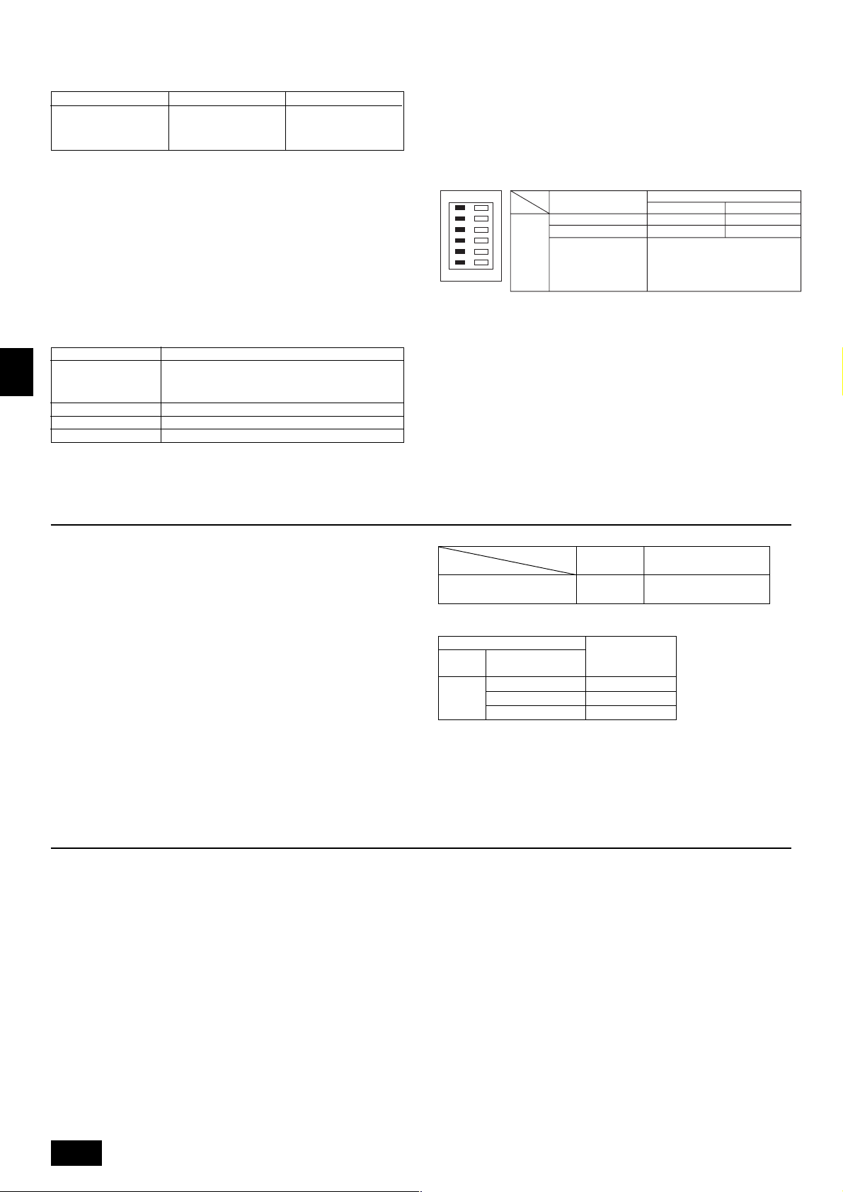
(2) Unit Function Selection
Set the functions of each unit from the remote controller, as required. The functions of each unit can be selected only from the remote controller.
Set the functions by selecting the necessary items from Table 1 and Table 2. (Default settings are also shown below)
Table 1. Itemized functions of the entire refrigerant system (select unit number 00 to 15)
Function
Power failure
automatic recovery
Indoor temperature
detection
LOSSNAY
connectivity
Power voltage
The weekly timer can be used.
on the left.
Not available
Available
Unit operating average
Set by unit’s remote controller
Remote controller’s internal sensor
Not Supported
Supported (unit is not equipped with outdoor-air intake)
Supported (unit is equipped with outdoor-air intake)
240 V
220 V, 230 V
ON/OFF] button.
ON/OFF] button.
ON/OFF] button (Choose one of the
ON/OFF] button.
Settings
• Setting the contact numbers
To set the contact numbers, follow the following procedures.
Move the flashing cursor to set numbers. Press the [
button to move the cursor to the right (left). Press the [
button to set the numbers.
[4] -4. Display change setting
(1) Temperature display °C/°F setting
• To switch the setting, press the [
1 °C: The temperature unit °C is used.
2 °F: The temperature unit °F is used.
(2) Suction air temperature display setting
• To switch the setting, press the [
1 ON: The suction air temperature is displayed.
2 OFF: The suction air temperature is not displayed.
(3) Automatic cooling/heating display setting
• To switch the setting, press the [
1 ON: One of “Automatic cooling” and “Automatic heating” is displayed under the
automatic mode is running.
2 OFF: Only “Automatic” is displayed under the automatic mode.
Mode no. Setting no. Check Default settings
01
02 2
03 2
04
1
2
1
3
1
3
1
2
ON/OFF] button.
ON/OFF] button.
ON/OFF] button.
Approx. 4-minute wait-period
after power is restored.
TEMP. ( ) and ( )]
CLOCK ( ) and ( )]
GB
Remarks
D
F
Table 2. Itemized functions of the unit (select unit numbers 01 to 04 or AL)
Function
Filter sign
Fan operation
during thermo off
in heating
operation
Fan operation
during thermo off
in cooling
operation
Note:
When the indoor unit functions were changed using the function selection after installation is complete, always indicate the set contents by entering 嘷 or other
mark in the appropriate check field of Table 1 and Table 2.
100 Hr
2500 Hr
No filter sign indicator
Operation
Stop
Operation
Stop
Settings
Mode no. Setting no. Check Default settings Remarks
07 2
25
27
1
3
3
2
1
2
When selecting fan operation
“Stop”, set setting no. of Mode
no. “02” in Table 1 to “3”. Be sure
to place the remote controller
inside the room to be air-conditioned so that it can monitor the
room temperature.
NL
SWI
E
P
11
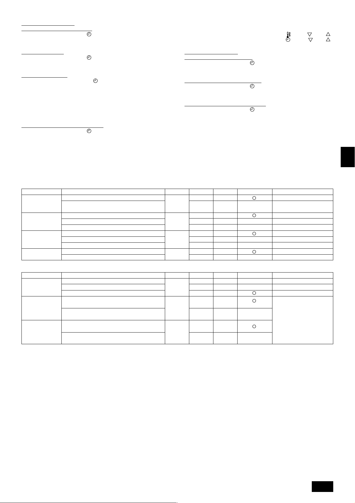
[Function selection flow]
First grasp the function selection flow. The following describes setting of “Power voltage” of Table 1 as an example.
(For the actual setting procedure, see [Setting procedure] 1 to 0.)
1 Check the function selection set contents.
2 Switch to the FUNCTION SELECTION mode.
(Press A and B simultaneously in the remote controller OFF state.)
3 Refrigerant address specification → 00 (Outdoor unit specification)
4 Unit address No. specification → 00 (Indoor unit specification)
(Buttons C and D operation)
5 Registration (Press button E.)
6 Mode No. Selection → 04 (Power voltage)
7 Setting No. selection → 2 (220 V, 230 V)
(Buttons F and G operation)
(Unnecessary for single refrigerant system.)
(Specified indoor unit →
Fan operation)
NO
YES
Change
refrigerant
address and unit
address No.?
F
TEMP.
MENU
E
G
BACK DAY
PAR-21MAA
ON/OFF
MONITOR/SET
CLOCK
OPERATION
ON/OFF
FILTER
CHECK
CLEAR
I
A
TEST
B
H
C
D
8 Register (Press button E.)
End?
NO
9
YES
0 Ending function display (Press buttons A and B simultaneously.)
GB
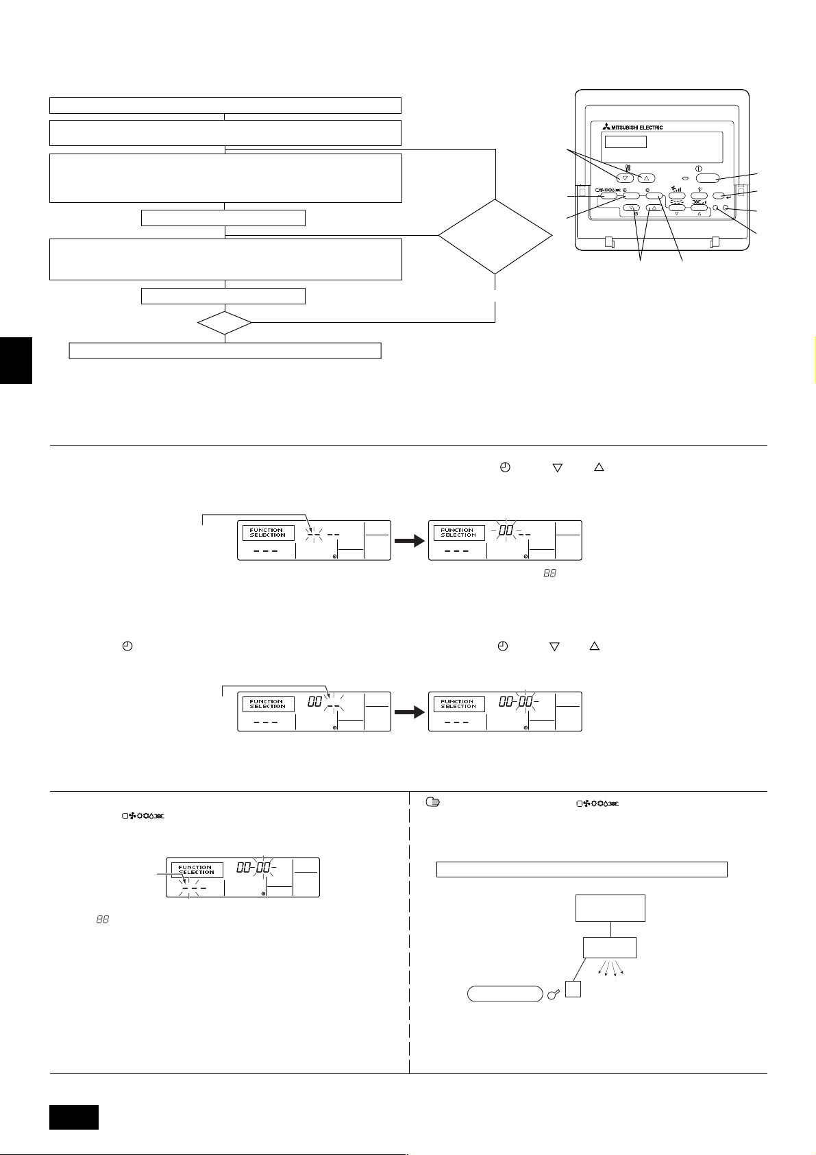
[Procedure] (Set only when change is necessary.)
1 Check the set contents of each mode. When the set contents of a mode were changed by function selection, the functions of that mode also change.
Check the set contents as described in steps 2 to 7 and change the setting based on the entries in the Table 1 and Table 2. (Refer default settings, when change the
setting)
D
2 Set the remote controller to Off.
Press and hold down the A [FILTER] and B [TEST] buttons at the same time
for two seconds or longer.
“FUNCTION SELECTION” blinks for a while, then the remote controller display
changes to the display shown below.
F
Refrigerant address display
* If the remote controller enters the OFF state after the “FUNCTION SELECTION” and room temperature displays “ ” have flashes for two seconds, communication is
probably abnormal. Make sure there are no noise sources near the transmission line.
Note:
If you make a mistake during operation, end function selection by step
NL
4 Set the indoor unit address No.
Press the D [
ON/OFF] button. The unit address No. display “– –” flashes.
??
? and repeat selection from step
??
3 Set the outdoor unit refrigerant address No.
When the C [
CLOCK ( ) and ( )] buttons are pressed, the refrigerant
address No. decreases and increases between 00 and 15. Set it to the refrigerant address No. whose function you want to select.
(This step is unnecessary for single refrigerant system.)
22
2.
22
When the C [ CLOCK ( ) and ( )] buttons are pressed, the unit address
No. changes in 00 → 01 → 02 → 03 → 04 → AL order. Set it to the unit address
No. of the indoor unit whose functions you want to set.
Unit address No. display
SWI
* When setting mode 01 to 04, set the unit address No. to “00”.
* When setting modes 07, 25, 27:
- When setting functions for a unit in an independent system, set the unit number to 01.
5 Refrigerant address and unit address No. registration
Press the E [ ] button. The refrigerant address and unit address No.
are registered.
After a while, the mode No. display “– –” flashes.
Mode No. display
E
* When “
address is not in the system.
When “F” is displayed at the unit address No. display, and when it flashes together with the refrigerant address display, the selected unit address No. does
not exist. Correctly set the refrigerant address and unit address No. by repeat-
P
ing steps 2 and 3.
” flashes at the room temperature display, the selected refrigerant
When registered using the E [ ] button, the registered indoor unit
begins fan operation. When you want to know the location of the indoor units of
the unit address No. whose functions were selected, check here. When the unit
address No. is 00 or AL, all the indoor units of the selected refrigerant address
perform the fan operation.
Ex) When refrigerant address 00, unit address No. = 01 registered
Refrigerant address 00
Outdoor side
Indoor side
Registration
Unit address
No. 01
Fan operation
Remote Controller
* When grouping by different refrigerant systems and an indoor unit other than
the specified refrigerant address performs the fan operation, the refrigerant
address set here is probably duplicated.
Recheck the refrigerant address at the outdoor unit DIP switches.
12
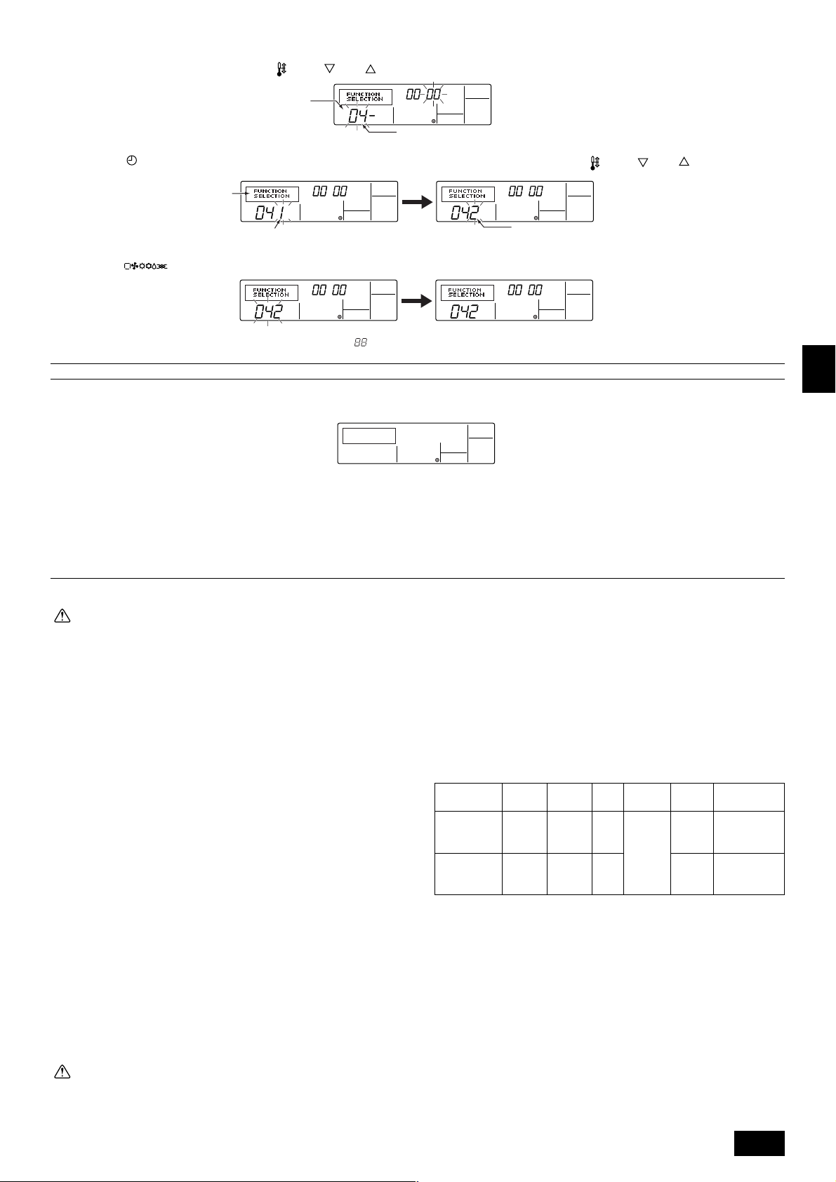
6 Mode No. selection
Select the mode No. you want to set with the F [
Mode No. display
7 Select the setting contents of the selected mode.
When the G [
Use this to check the currently set contents.
MENU] button is pressed, the current setting No. flashes.
Setting No. display
TEMP. ( ) and ( )] buttons. (Only the settable mode numbers can be selected.)
Mode No. 04 = Power voltage
Select the setting No. using the F [
TEMP. ( ) and ( )] buttons.
Setting No. 1 = 240 V
8 The contents set at steps 3 to 7 are registered.
When the E [
and setting ends.
* When “– –” appears at the mode No. and setting No. displays and “
Make sure there are no noise sources near the transmission line.
9 To select more functions, repeat steps 3 to 8.
0 End function selection.
Press and hold down the A [FILTER] and B [TEST] buttons at the same time for two seconds or longer.
After a while, the function selection display disappears and the remote controller returns to the air conditioner off display.
* Do not operate the air conditioner from the remote controller for 30 seconds after the end of function selection.
Note:
When the functions of an indoor unit were changed by function selection after the end of installation, always indicate the set contents by entering a 嘷 or other
mark in the appropriate check field of Table 1 and Table 2.
] button is pressed, the mode No. and setting No. flash and registration begins. The flashing mode No. and setting No. change to a steady light
” flashes at the room temperature display, communication is probably abnormal.
Setting No. 2 = 220 V, 230 V
9. Electrical wiring
Precautions on electrical wiring
Warning:
• Electrical work should be done by qualified electrical engineers in accordance with “Engineering Standards For Electrical Installation” and supplied installation manuals. Special circuits should also be used. If the
power circuit lacks capacity or has an installation failure, it may cause a
risk of electric shock or fire.
• Always use the designated cable for wiring, and connect it correctly. Secure it so that the cable applies no external pressure to the terminal connection. If the connection is faulty or the cable is not fully secured, overheating or fire could result.
• Be sure to use specified cables and connect them firmly so that no external wiring force is exerted on terminal connections. Loose connections
may cause heat or fire.
1. Be sure to take power from the special branch circuit.
2. Be sure to install an earth leakage breaker to the power.
3. Install the unit to prevent that any of the control circuit cables (remote controller) is brought in direct contact with the power cable outside the unit.
4. Ensure that there is no slack on all wire connections.
5. Remote controller cable above the ceiling may be bitten by mice. Use as many
metal pipes as possible to insert the cable into them for protection. Where the
remote controller cable is exposed, protect the cable by running it through a
metal pipe.
6. Never connect the power cable to leads for the remote controller cables. Otherwise the cables would be broken.
7. Fix power source wiring to control box by using buffer bushing for tensible force
(PG connection or the like).
8. Set up the unit so that the wiring for the remote controller and the M-NET
(MELANS) wiring do not produce electrical interference with the power supply
cable. (Do not route them together in the same conduit.)
9. Be sure to provide designated grounding work to the unit.
10. Give some allowance to wiring for electrical part box of the unit, because the
box is sometimes removed at the time of service work.
Caution:
• Be sure to put the unit to the ground on the outdoor unit side. Do not
connect the earth cable to any gas pipe, water pipe, lightening rod, or
telephone earth cable. Incomplete grounding may cause a risk of electric
shock.
• Some installation sites may required installation of an earth leakage
breaker. Failure to install it may result in an electric shock.
• Always use an earth leakage breaker and fuse with the specified capac-
ity. Use of a fuse with a capacity larger than that specified, or use of a
piece of wire or copper wire may cause breakdown or fire.
• Depending on the location of the unit, a current leakage breaker may be
required. If a current leakage breaker is not installed, electric shock could
result.
• Do not use breakers or fuses with a capacity different from the correct
one. If large-capacity fuses, wire, or copper wiring are used, accident or
fire may result.
The following table is an example. The selection of other capacities should be
determined in accordance with the relevant standards.
[Wiring example] (For metal pipe)
Pow er
Breaker
Capacity
Cable
2
PRH-P400MYA
PRH-P500MYA
Note:
*1: This device is intended for the connection to a power supply system with
a maximum permissible system impedance ZMAX of 0.06
0.04
supply.
The user has to ensure that this device is connected only to a power
supply system which fulfills the requirement above.
If necessary, the user can the ask the public power supply company for
the system impedance at the interface point.
16 mm
or thicker
25 mm
or thicker
63 A 63 A
2
70 A 70 A
Ω: PRH-P500 at the interface point (power service box) of the user’s
Fuse
Remote
controller
cable
Cable or
wire of
0.3 ~
1.25 mm
(Max. DC
12 V)
Ground-
ing wire
16 mm
2
25 mm
or
thicker
or
thicker
Max. Permissive
system
impedance *1
2
0.06 Ω
2
0.04 Ω
Ω: PRH-P400,
13
GB
D
F
NL
SWI
E
P
[Selecting earth leakage breaker (NV)]
To select NF or NV instead of a combination of Class B fuse with switch, use the
following:
Fuse (class B) 63 A 70 A
Earth leakage NV100-SW NV100-SW
breaker ELB 60 A 75 A
(with over-load protection) 100 mA 0.1s or less 100 mA 0.1s or less
NV is a product name of MITSUBISHI.
• Power supply cords of appliances shall not be lighter than design 245 IEC57.
• A switch with at least 3 mm contact separation in each pole shall be provided
by the Air conditioner installation.
Example
[Fig. 9.0.1] (P.4)
(1) Normal Connecting
(2) Grouping (8 units)
A Power supply B Earth leakage breaker
C Wiring circuit breaker or isolating switch
D Remote controller E Address
[Unit-MA remote controller cable/cord] (For metal pipe)
MA remote controller
2 core cable
0.3 ~ 1.25 mm
Max. 200 m
2
Types of cable/cord
GB
Number of cable/cord
Diameter of cable/cord
Total extention
When extending the remote controller cable,
remote controller cables shall not be
lighter than design 245 IEC53.
D
9.1. Address settings
Unit address settings
• During address setting, set all the dip switches SW1 (3 - 6) on the outdoor-side
controller board to <when shipped from factory: 00, 01>. (Address setting is
not necessary for 1:1)
• Functions of SW1 according to switch setting are shown below.
• To control a group of units, address must be assigned to each unit.
(SW1 of outdoor-side contoroller)
OFF ON
1
2
3
4
5
6
[Fig. 9.1.1] (P.5)
1–
2 Error history clear
3 Refrigerant system
address setting
4 ↑
switching
5 ↑
SW1 function
6 ↑
Model
Functions according to switch setting
ON
–
Clear
Unit address
Settings 0 ~ 15
OFF
–
Ordinary
9.2. Wiring connection
• Using the conduit mounting plates
Conduit mounting plates are supplied in two sizes (ø40, ø52). Use the mounting plate that fits the outer diameter of the wire to be used.
[Fig. 9.2.1] (P.5)
A When installing conduct from bottom panel
B When installing conduct from front panel
C Mounting plate (attached)
D Knock-out hole
10. Specifications for installing the belt
1. Set the parallel angle of the fan and the motor pulley as shown in the
[Fig. 10.0.1] and table 1.
F
2. Set the tension of the per one belt when the flexion load is within the range as
shown in the [Fig. 10.0.2] and table 2 below at the proper flexion.
3. Adjust the suitable tension after the belt sit properly across the pulley (after
more 24 - 28 hours working).
When the new belt is used, adjust the suitable tension about the 1.3 times of
the maximum value of the flexion load.
4. Readjust the belt every 2,000 hours after the first adjustment.
NL
Exchange the belt when the belt’s surroundings length has expanded by 2 %
including the first expansion of the belt. (about 1 %)
(about 8,000 hours converted working time)
When selecting fan operation “Stop” (Mode no. 25 “2” in table 2 of page 11),
readjust the belt every 1,000 hours after the first adjustment.
[Fig. 10.0.1] / [Fig. 10.0.2] (P.5)
SWI
<A> Parallel degree of pulley
<B> Belt tension
A Flexion load (W)
table 1
pulley
table 2
type
pulley
pulley
smaller out diameter
B
parallel angle
10 or less
(mm)
~ 135
136 ~ 160
161 ~
11. Modification method of fan direction (From side flow to top flow)
This product can be changed from side flow to top flow in the field.
Modify if necessary as follows.
[Fig. 11.0.1] (P.5)
E
A Top panel B Cover (outer side) C Flange
D Panel E Fan F Cover (inner side)···2pcs
1 Remove the top panel A, cover (outer side) B, flange C, panel D and cover
(inner side) F. (STEP 1)
2 Modify the fan E direction. (STEP 2)
When working with the fan E suspended, do not rope the shaft of the fan.
3 Re-install the top panel A, cover B, flange C and panel D. (STEP 3)
* Between flange C, top panel A, and screw fittings should be adequately
waterproofed.
K (
"
)
gap of 3 mm every 1 m
Flexion load W
(N)
22 ~ 29
27 ~ 34
29 ~ 37
note
P
14
Note:
In the case of top flow, the inner cover
FF
F is not necessary.
FF
12. Test run
12.1. Before test run
The test run can be carried out either from the unit or remote controller.
1. Checklist
• After wiring of units are complete, check that refrigerant is not leaking, the
power and control wires are not loose, and the poles are not reversed.
• Use a 500 V insulation resistance tester to make sure that the resistance between the power terminal and the ground is 1.0 MΩ or more. If it is less than
1.0 MΩ, do not operate the unit.
• Make sure there is no malfunction in the unit. (If there is a malfunction, you
can diagnose it using LED1 on the outdoor-side controller board.)
• Check the electrical power phase. If the phase is reversed, the fan may rotate
in the wrong direction or stop, or unusual sounds may be produced.
• Starting at least 12 hours before the test run, send current through the
crankcase heater. (If the current is running for a shorter period of time,
damage to the compressor could result.)
• For specific models requiring changing of settings for selection of power supply ON/OFF capability, make proper changes referring to the description for
Selection of Functions through Remote Controller.
After the above checks are complete, carry out the test run as indicated in the
following outline.
4 Check the outdoor-side fan for correct running
The unit features automatic capacity control to provide optimum outdoor-side
fan speeds. The fan keeps running at a low speed to meet the current outside
air condition unless it exceeds its available maximum power. Then, in actuality,
the fan may stop or run in the reverse direction depending on the outside air,
which does not mean malfunction.
5 Press the [
ON/OFF] button to reset the test run in progress
• The test run will be automatically shut down after two hours in response to the
AUTO STOP setting of two hours on the timer.
• During the test run, the room temperature display shows the unit indoor-side
liquid piping temperatures.
• In the case of the test run, the OFF timer will activate, and the test run will
automatically stop after two hours.
• The room temperature display section shows the control temperature for the
units during the test run.
• Check that the units are running properly operation.
Malfunctions may not be displayed even if the wiring is incorrect.
6 Register a telephone number
The telephone number of the repair shop, sales office, etc., to contact if an
error occurs can be registered in the remote controller. The telephone number
will be displayed when an error occurs.
For registration procedures, refer to 8.4 Function selection of remote control-
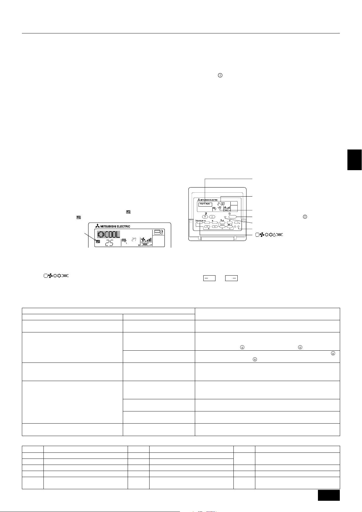
12.2. Test run procedures
1) Remote controller
Operating procedures
1 Turn on the main power supply
While the display on the remote controller indicates “
is disabled. Turn off the “
“CENTRALLY CONTROLLED”
indicator
” indicator before using the remote controller.
2 Press the [TEST] button twice successively within three seconds. Test
run starts.
“TEST RUN” and “OPERATION MODE” are displayed alternately.
3 Press [
] button
Cooling mode: Cool air should start to blow.
Heating mode: Warm air should start to blow (after a while).
”, the remote controller
˚C
TEMP.
˚C
ON/OFF
ler.
MENU
MONITOR/SET
BACK DAY
PAR-21MAA
TEMP.
˚C
ON/OFF
ON/OFF
CLOCK
OPERATION
FILTER
CHECK
CLEAR
Operation mode display
“TEST RUN” and “OPERATION MODE” are
displayed alternately.
Timer stops test run after two hours.
Piping temperature display
Stop test run by pressing the [ ON/OFF] button.
During test run, the RUN lamp remains on.
TEST
[TEST] button
[ ] button
(*1)
After turning ON the power, the system will go into startup mode, and the remote
controller operation lamp (green) and the display section’s “PLEASE WAIT” will
flash. Also, in the case of the indoor-side controller board substrate LEDs, LED 1
and LED 2 light up (when address is 0) or become dim (when address is not 0), and
LED 3 flashes. In the case of the outdoor-side controller board substrate LED 1
display,
and are displayed alternatively at 1-second intervals.
• If one of the above operations does not function correctly, the following causes
should be considered, and if applicable, dealt with. (The following symptoms
have been determined under test run mode. Note that “startup” in the chart
means the *1 display above.)
Remote Controller Display Outdoor Substrate LED Display
Symptoms
Remote controller is displaying “PLEASE WAIT”, and
operation is not possible.
After power is turned ON, “PLEASE WAIT” is displayed for 3 mins., then error code is displayed.
Power is turned ON, and “EE” or “EF” are displayed
after “PLEASE WAIT” is displayed.
After “startup” display, “00” is displayed (correct operation).
After “startup” display, error code is
displayed.
After “startup” display, “F1” (negative
phase) is displayed.
After “startup” display, “00” or “EE” is
displayed (“EE” is displayed when a
• After power is turned ON, system star tup lasts for about 2 mins., and
“PLEASE WAIT” is displayed (correct operation).
• Outdoor-side unit’s safeguard installation connector is open.
• Negative phase and open phase of outdoor unit’s power terminal board
(Single phase: L, N,
• Incorrect connection of outdoor terminal board (Single phase: L, N,
triple phase: L1, L2, L3, N,
• Unit construction differ
Cause
/triple phase: L1, L2, L3, N, )
grounding and S1, S2, S3)
test run is made).
Display messages do not appear even when remote
controller operation switch is turned ON (operation
lamp does not light up).
After “startup” display, “EA” (error for
number of units) or “Eb” (unit number
error) is displayed.
After “startup” display, “00” is dis-
• Wiring for the unit is not connected correctly. (Polarity is wrong for S1, S2,
S3)
• Remote controller transmission wire short
• There is no unit for address 0 (address is something other than 0).
played (correct operation).
After “startup” display, “00” is dis-
• Remote controller transmission wire burnout
played (correct operation).
Operation display appears but soon disappears even
when remote controller operations are executed.
After “startup” display, “00” is dis-
played (correct operation).
• After cancellation of function selection, operation is not possible for about
30 secs. (correct operation).
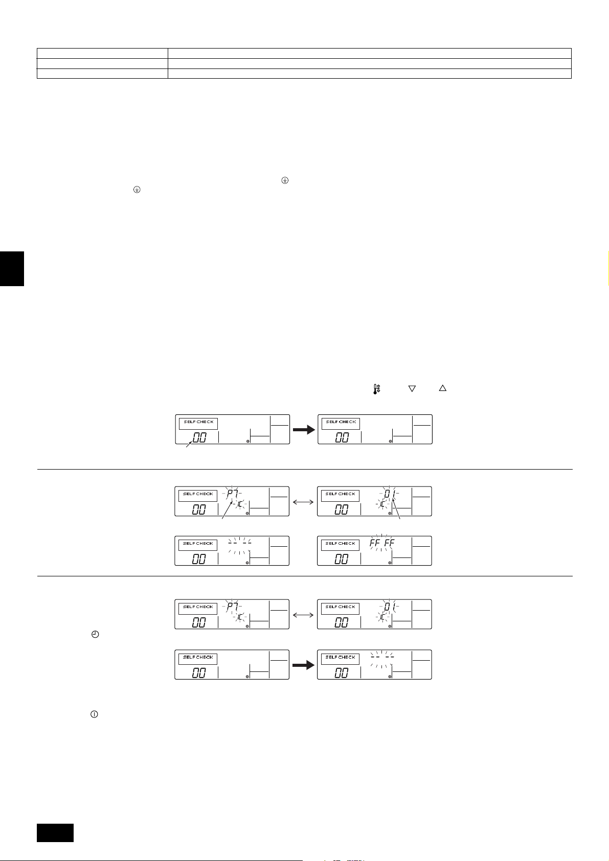
* Press the remote controller’s “CHECK” button twice consecutively to be able to run a self-check. See the chart below for content of error code displays.
LCD Nonconformity Content
P1 Suction sensor error
P2 Piping (liquid pipe) sensor error
P4 Drain sensor error
P5 Drain overflow safeguard operation
P6 Freezing/overheating safeguard operation
LCD Nonconformity Content LCD Nonconformity Content
P8 Pipe temperature error
P9 Piping (2-phase pipe) sensor error
U0 - UP Unit nonconformity
F1 - FA Unit nonconformity
E6 - EF Signal error between indoor-side controller
board and outdoor-side controller board
- - - - No error history
FFFF No relevant unit
E0 - E5 Signal error between remote controller and
unit
GB
D
F
NL
SWI
/
E
P
15
See the chart below for details of the LED displays (LED 1, 2, 3) on the indoor-side controller board.
LED 1 (microcomputer power supply) Displays the ON/OFF of power for control. Check that this is lit during normal use.
LED 2 (remote controller feed) Displays the ON/OFF of feed to wired remote controller. Is only lit for the unit of outdoor-side controller board with address “00”.
LED 3 (indoor and outdoor signals) Displays signal between indoor-side and outdoor-side controller boards. Check that this is flashing during normal use.
2) Unit
1) Check Items
• After installation of the unit, and electric wiring work, check that the unit is free
from leaks of refrigerant, loosened connections, and incorrect polarity.
• Check that there is no negative phase and open phase. (The F1 message for
negative phase and the F2 message for open phase will flash at LED 1 on the
outdoor-side controller board. If this happens, rewire correctly.)
• Measure the impedance between power terminals (Single phase: L, N, /
triple phase: L1, L2, L3, N,
that it is 1.0 MΩ or more. Do not operate the equipment if measurement is less
than 1.0 MΩ.
• When there is no error at the unit.
(If there is an error at the unit, it can be evaluated at LED 1 [digital display] of
the outdoor-side controller board.)
•
The stop valves are open both the liquid and gas sides.
After checking the above, execute the test run in accordance with the following.
2) Test run start and finish
GB
The following setting is valid for only one applicable system. Make the same
setting to the other systems, so that the test run can be performed.
• Operation from the indoor-side controller board
Execute the test run using the installation manual for the indoor-side controller
board.
) and the ground with a 500 V Megger and check
D
12.3. Self-check
Retrieve the error history of each unit using the remote controller.
1 Switch to the self check mode.
When the H [CHECK] button is pressed twice successively within three seconds, the display shown below appears.
F
• Operation from the outdoor-side controller board
Execute settings for test run start, finish and operation mode (cooling, heating)
using the DIP switch SW 4 on the outdoor-side controller board.
[Fig. 12.2.1] (P.5)
A Stop B Cooling
C Operation D Heating
1 Set the operation mode (cooling, heating) using SW 4-2
2 Turn ON SW 4-1, The operation mode for SW 4-2 will be adhered to, and
the test run will commence
3 Turn OFF SW 4-1 to finish the test run
• There may be a faint knocking noise emitted from the proximity of the fan
during the test run. This is torque fluctuation occurring due to control of fan
revolutions. There is no problem with the product.
Note:
The SW 4-2 operation mode cannot be changed during the test run. (To change
test run mode, stop the equipment with SW 4-1, change the operation mode,
then restart test run with SW 4-1.)
• If the 2-hour timer is set, the test run will stop automatically after 2 hours.
• During the test run, the room temperature display shows the unit indoor-side
liquid piping temperatures.
2 Set the address or refrigerant address No. you want to self check.
When the F [
creases and increases between 01 and 50 or 00 and 15. Set it to the address
No. or refrigerant address No. you want to self check.
TEMP. ( ) and ( )] buttons are pressed, the address de-
Self check address or self check refrigerant address
NL
3 Self check result display <Error history> (For the contents of the error code, refer to 13. Troubleshooting, error code list.)
ERROR CODE
Error code 4 digits or error code 2 digits
SWI
4 Error history reset
The error history is displayed in 3 Self check results display.
When the D [ MENU] button is pressed twice successively within three seconds, the self check address or refrigerant address flashes.
<When there is no error history>
ERROR CODE ERROR CODE
ERROR CODE ERROR CODE
E
5 Self check reset
There are the following two ways of resetting self check.
Press the H [CHECK] button twice successively within three seconds → Resets self check and returns to the state before self check.
Press the I [
P
ON/OFF] button → Self check resets and indoor units stop.
(When operation is prohibited, this operation is ineffective.)
Approximately three seconds after the change operation, the self check refrigerant address changes from flashing to a steady light and self check begins.
<When opposite side does not exist>
When the error history was reset, the display shown below appears.
When error history reset failed, the error contents are displayed again.
Address 3 digits or unit address No. 2 digits
ERROR CODE
16
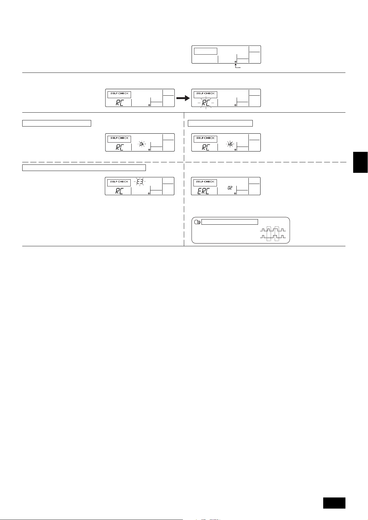
12.4. Remote controller check
If operation cannot be carried out from the remote controller, use this function to diagnose the remote controller.
1 First check the power mark.
When normal voltage (DC12V) is not applied to the remote controller, the power
mark goes off.
When the power mark is off, check the remote controller wiring and the indoor
unit.
2 Switch to the remote controller check mode.
When the H [CHECK] button is held down for five seconds or longer, the display shown below appears.
3 Remote controller check result
When remote controller is normal
When the A [FILTER] button is pressed, remote controller check begins.
When remote controller is faulty
(Error display 1) “NG” flashes → Remote controller send/receive circuit abnormal
Power mark
Since there is no problem at the remote controller, check for other causes.
When the problem is other than the checked remote controller
(Error code 2) “E3” “6833” “6832” flash → Cannot send
ERROR CODE
There is noise on the transmission line, or the indoor unit or another remote controller is faulty. Check the transmission line and the other remote controllers.
4 Remote controller check reset
When the H [CHECK] button is held down for five seconds or longer, remote controller check resets and the “PLEASE WAIT” and RUN lamp flash. Approximately 30
seconds later, the remote controller returns to the state before remote controller check.
Remote controller switching is necessary.
(Error display 3) “ERC” and data error count are displayed → Data error generation
“Data error count” is the difference between the number of bits of remote controller
send data and the number of bits actually sent to the transmission line. In this case,
the send data was disturbed by the noise, etc. Check the transmission line.
When data error count is 02
Remote controller send data
Send data on transmission line
GB
D
F
NL
SWI
17
E
P
13. Troubleshooting
13.1. How to handle problems with the test run
Error code list: details
GB
D
F
NL
Remote controller
display
E0
E1, E2
E3
E4
E5
E6
E7
E8
E9
EA
EB
EC
ED
EE
F1
F8
A0
A2
A3
A6
A7
A8
EF
U2
U2
U3
U4
U6
UE
UL
F8
P1
P2
P4
P5
P5
P6
P6
P8
P9
MELANS display
6831,6834
6201,6202
6832,6833
6831,6834
6832,6833
6740,6843
6841,6842
6840,6843
6841,6842
6844
6845
6846
0403
0403
4103
4115
6600
6602
6603
6606
6607
6608
undefined
1102
1108
5104
5105
4101
1302
1300
4115
5101
5102
2503
2502
2500
1503
1504
1110
5103
Remote controller communication – reception error
Remote controller board error
Remote controller communication – transmission error
Remote controller communication – reception error
Remote controller communication – transmission error
Communication between indoor-side and outdoor-side controller boards – reception error
Communication between indoor-side and outdoor-side controller boards – transmission error
Communication between indoor-side and outdoor-side controller boards – reception error
Communication between indoor-side and outdoor-side controller boards – transmission error
Connection wiring error (interference, loose)
Connection wiring error (interference, loose)
Excessive time in use
Serial communication error
Serial communication error
Reverse phase, out of phase verification
Faulty input circuit
Duplicated M-NET address setting
M-NET error in PH/W transmission
M-NET bus busy
M-NET communication error with P transmission
M-NET error – no ACK
M-NET error – no response
Undefined error code
Discharge temperature error
CN23 Short-circuit Connector Unplugged
Open/short in discharge temp thermistor
Open/short in liquid temp or condenser/evaporater temp thermistor
Compressor overcurrent interruption (51C operation)
High pressure error (63H1 operation)
Low pressure error (63L operation)
Power synchronous idle circuit error
Inlet sensor error
Piping (liquid pipe) sensor error
Drain sensor error
Drain overflow protector operation
Water leak error
Freeze prevention operation
Surge prevention operation
Piping temperature error
Piping (2-phase pipe) sensor error
Error details
Problem location
Remote Controller
Remote Controller
Remote Controller
Indoor-side controller board
Indoor-side controller board
Indoor-side controller board
Indoor-side controller board
Outdoor-side controller board
Outdoor-side controller board
Outdoor-side controller board
Outdoor-side controller board
Outdoor-side controller board
Outdoor-side controller board
M-NET board
Outdoor-side controller board
Outdoor-side controller board
M-NET board
M-NET board
M-NET board
M-NET board
M-NET board
M-NET board
–
Outdoor-side controller board
Outdoor-side controller board
Outdoor-side controller board
Outdoor-side controller board
Outdoor-side controller board
Outdoor-side controller board
Outdoor-side controller board
Outdoor-side controller board
Indoor-side controller board
Indoor-side controller board
Indoor-side controller board
Indoor-side controller board
Indoor-side controller board
Indoor-side controller board
Indoor-side controller board
Indoor-side controller board
Indoor-side controller board
SWI
E
P
18

• Depending on the position of the SW2 switch on the outdoor unit board, the segments light up to indicate the running condition of the unit and the particulars of the check
code.
SW2 setting
123456
000000
Operation mode/relay output
Item
tens place O: stop
C: cooling
H: heating
d: defrosting
units place 1: SV1
2: 21S4
4: 52C
When an error occurs, the error code
and error signal (*1) are displayed in
alternation.
Display contents
Relay output = SV1 + 21S4 + 52C
Ex. During cooling mode, when 52C and SV1 are ON: C5
011110
010110
011100
111100
*1 Display system for error indicator
The indicator corresponds to the following numbers
0 ............. Outdoor unit (OC1, OC2)
1 ............. Indoor unit (IC1, IC2)
Outdoor unit control condition
Indoor-side control condition (IC1)
Error code history 1
Error code history 2
Control mode display system
Nothing
The error code (ex. U8, UA) and error indicator (*1) are displayed in alternation.
Indoor-side
Outdoor-side
Display
0
1
2
3
4
5
6
7
Hot adjustment
Freeze prevention
Surge prevention
Compressor OFF
Control mode
Indoor-side
Ordinary
Defrosting
—
Heater ON
Outdoor-side
←
←
←
←
←
←
←
←
13.2. The following occurrences are not problems or errors
Problem
The fan setting changes during heating.
The fan stops during heating.
When the switch is turned ON, the fan does
not begin to operate.
The outdoor-side fan turns in reverse or stops,
and an unusual sound is heard.
Note:
If indoor-side fan does not operate, check the over-current relay on the fan motor to determine whether it has been tripped.
If the over-current relay has been tripped, reset it after eliminating the cause of the problem (e.g. motor lock).
To reset the over-current relay, open the control box and press the green claw on bottom-right of the relay until a click is heard. Release the claw and check that
it returns to its original position.
Note that if it is pressed too hard it will not return to its original position.
Remote controller display
Ordinary display
Defrosting display
Heating preparations
underway
Ordinary display
Cause
During thermostat OFF mode, light air or low air operation will take place.
During thermostat ON mode, light air or low air will switch automatically to set notch on
the basis of time or piping temperature.
During defrosting, the fan will stop.
After the switch is turned to ON or until the piping temperature reaches 35°C, there will
be 5 minutes of light air operation. After that there will be 2 minutes of low air operation,
then set notch will begin (hot adjustment control).
There is a risk of the power to the unit being connected in reverse phase. Be sure to
check that the phase is correct.
GB
D
F
NL
SWI
14. System control
14.1. System settings
[Fig. 14.1.1] (P.5)
A Unit B Main remote controller
C Subordinate remote controller D Refrigerant address = 00, 01
E Refrigerant address = 02, 03 F Refrigerant address = 04, 05
* Set the refrigerant address using the DIP switch of the outdoor-side controller
board.
1 Wiring from the Remote Control
This wire is connected to TB5 (terminal board for remote controller) of the unit
(non-polar).
2 When a Different Refrigerant System Grouping is Used
Up to 16 refrigerant systems can be controlled as one group using the MA remote
controller.
PRH-P400, 500MYA has two refrigeration systems per unit.
Note:
In single refrigerant system, there is no need of wiring
SW1
Function table
<SW1>
ON
OFF
123456
SW1
function
settings
Function
1 Compulsory de-
frosting
2 Error history clear
3
Refrigerant sys-
4
tem address set-
5
ting
6
Operation according to switch setting
ON OFF
Start Normal
Clear Normal
Settings for outdoor unit addresses 0 to 15
22
2.
22
E
P
19
14.2. Examples of refrigerant system address
setting
Ex.
1
* Set the refrigerant system address of one unit to 00 for the power supply to the
remote controller.
(The refrigerant system address is set to 00 (OC1), 01 (OC2) when shipped from
the factory.)
Do not duplicate the refrigerant system address settings within the same system.
Unit
PRH-P400,
500MYA
Unit
OC1
OC2
Unit refrigerant
system address
00
01
Remote controller
power supply unit
14.3. Capacity control setting method (PRHP400, 500MYA only)
With the PRH-P400, 500MYA which has two outdoor-side units, the capacity can
be controlled to 0 %, 50 % or 100 %.
This is set by setting the outdoor-side unit side dip switches as shown in the table
below before turning the power on.
DipSW5-1
No.1 outdoor-side unit
OFF
No.2 outdoor-side unit
ON
GB
D
⳯
F
NL
SWI
E
P
20
Inhalt
1. Sicherheitsvorkehrungen .......................................................................... 21
1.1. Vor Installations- und Elektroarbeiten...................................... 21
1.2. Vorsichtsmaßnahmen für Vorrichtungen, die das Kältemittel
R407C verwenden ................................................................... 22
1.3. Vor der Aufstellung .................................................................. 22
1.4. Vor dem Einbau (der Ortsveränderung) - Elektroarbeiten ....... 22
1.5. Vor Installationsbeginn ............................................................ 22
2. Zubehör .................................................................................................... 23
3. Einen Aufstellort wählen ........................................................................... 23
3.1. Vorgeschriebener Freiraum um das Anlage ............................ 23
4. Hebemethode und Gewicht der Klimaanlage ........................................... 23
5. Einbau der Klimaanlage ............................................................................ 23
5.1. Einbau ..................................................................................... 23
6. Rohrleitungen verlegen ............................................................................. 24
7. Arbeiten am Strömungskanal ................................................................... 24
7.1. Frischluftzufuhr, Strömungskanalinstallation und Betriebsein-
schränkungen .......................................................................... 24
8. Fernbedienung .......................................................................................... 24
8.1. Installationsabläufe .................................................................. 24
8.2. Anschlußverfahren .................................................................. 25
1. Sicherheitsvorkehrungen
1.1. Vor Installations- und Elektroarbeiten
s Vor dem Einbau der Anlage vergewissern, daß Sie alle Infor-
mationen über “Sicherheitsvorkehrungen” gelesen haben.
s Die “Sicherheitsvorkehrungen” enthalten sehr wichtige
Sicherheitsgesichtspunkte. Sie sollten sie unbedingt befolgen.
Im Text verwendete Symbole
Warnung:
Beschreibt Vorkehrungen, die beachtet werden sollten, um den Benutzer vor
der Gefahr von Verletzungen oder tödlicher Unfälle zu bewahren.
Vorsicht:
Beschreibt Vorkehrungen, die beachtet werden sollten, um die Anlage vor
Schäden zu bewahren.
An der Anlage angebrachte Zeichen
: Verweist auf eine Handlung, die unterbleiben muß.
: Verweist auf wichtige Anweisungen, die befolgt werden müssen.
: Verweist auf ein Teil, das geerdet werden muß.
: Zeigt an, daß bei rotierenden Teilen Vorsichtgeboten ist. (Dieses Symbol
findet sich als Aufkleber auf der Hauptanlage.) <Farbe: gelb>
: Gefahr von elektrischem Schlag. (Dieses Symbol findet sich als Aufkleber
auf der Hauptanlage.) <Farbe: gelb>
Warnung:
Die auf der Hauptanlage angebrachten Aufkleber sorgfältig lesen.
Warnung:
• Bitten Sie Ihren Fachhändler oder einen geprüften Fachtechniker, die Installation der Anlage vorzunehmen.
- Unsachgemäße Installation durch den Benutzer kann Wasseraustritt, Strom-
schläge oder Brände verursachen.
• Die Anlage an einem Ort installieren, der genügend Tragkraft für deren
Gewicht besitzt.
- Bei ungenügender Tragkraft kann das Anlage herunterfallen und Verletzun-
gen verursachen.
• Zur Verdrahtung die angegebenen Kabel verwenden. Die Anschlüsse so
sichern, daß Zugspannung von außen nicht auf die Klemmen wirken kann.
- Falscher Anschluß und falsche Befestigung führen zu Wärmebildung und
verursachen Brände.
• Vorsorge gegen heftige Windstöße und Erdbeben treffen, und die Anlage
an dem angegebenen Ort installieren.
- Durch unsachgemäße Installation kann die Anlage herunterfallen und Ver-
letzungen verursachen.
• Stets Zubehör gemäß Angaben von Mitsubishi Electric verwenden.
- Einen geprüften Techniker bitten, die Zusatzeinrichtungen zu installieren.
Unsachgemäße Installation durch den Benutzer kann zu Wasseraustritt,
Stromschlägen oder Bränden führen.
8.3. Anbringung des oberen Kastens ............................................. 25
8.4. Funktionswahl.......................................................................... 25
9. Elektroverdrahtung .................................................................................... 29
9.1. Einstellung der Adresse .......................................................... 29
9.2. Kabelanschluß ......................................................................... 29
10. Installation des Riemens ........................................................................... 30
11. Änderung der Gebläserichtung (von seitlichen Zufuhr auf Zufuhr von oben) .... 30
12. Testlauf ..................................................................................................... 30
12.1. Vor dem Testlauf ...................................................................... 30
12.2. Testlaufverfahren ..................................................................... 30
12.3. Selbsttest ................................................................................. 32
12.4. Test der Fernbedienung .......................................................... 33
13. Fehlerbehebung ........................................................................................ 34
13.1. Handhabung von Problemen beim Testlauf ............................. 34
13.2. Die folgenden Erscheinungen stellen keine Probleme oder
Fehler dar ................................................................................ 35
14. Kontrolle des Systems .............................................................................. 35
14.1. Systemeinstellungen ............................................................... 35
14.2. Beispiele für die Kältemittel-Adresseneinstellung ................... 36
14.3. Einstellungsverfahren für Kapazitätssteuerung
(nur PRH-P400, 500MYA) ....................................................... 36
• Die Anlage niemals selbst reparieren. Wenn die Anlage repariert werden
muß, wenden Sie bitte sich an den Fachhändler.
- Wenn die Anlage unsachgemäß repariert wird, kann dies zu Wasseraustritt,
Stromschlägen oder Bränden führen.
• Nicht die Wärmetauscherleitung berühren.
- Unsachgemäße Handhabung kann zu Verletzungen führen.
• Tragen Sie bei der Handhabung dieses Erzeugnisses immer Schutzausrüstung, d.h. Handschuhe, vollen Armschutz wie einen Overall und eine
Schutzbrille.
- Unsachgemäße Handhabung kann zu Verletzungen führen.
• Die Anlage gemäß Anweisungen in diesem Installations-handbuch installieren.
- Bei unsachgemäßer Installation kann dies zu Wasseraustritt, Stromschlägen
oder Bränden führen.
• Elektroarbeiten durch einen zugelassenen Fachelektriker in Übereinstimmung mit dem “Electric Facility Engineering Standard” - (Technische
Normen für Elektroeinrichtungen), den “Interior Wire Regulations” - (Vorschriften zur Innenverdrahtung) und den in diesem Handbuch gegebenen Anweisungen vornehmen. Anlage auch immer an einen gesonderten Stromkreis anschließen.
- Wenn die Leistung der Stromquelle ungenügend ist oder die Elektroarbeiten
unsachgemäß ausgeführt wurden, kann dies zu Stromschlägen und zu Bränden führen.
• Die Abdeckung der Elektroanschlüsse (Abdeckplatte) fest anbringen.
- Wenn die Abdeckung der Elektroanschlüsse (Abdeckplatte) nicht sachge-
mäß angebracht wurde, kann Staub oder Wasser in die Anlage eindringen
und Brände oder Stromschläge verursachen.
• Nach Verbringen an einen anderen Standort Anlage nur mit dem vorgeschriebenen Kältemittel (R407) füllen.
- Wenn das ursprüngliche Kältemittel mit einem anderen Kältemittel oder mit
Luft vermischt wird, kann dies zu Fehlfunktionen des Kältemittelkreislaufs
führen und die Anlage beschädigt werden.
• Beim Verbringen der Anlage an einen anderen Ort einen Fachhändler
oder einen geprüften Techniker zur Neuaufstellung hinzuziehen.
- Bei unsachgemäßer Installation der Anlage kann Wasser austreten, und es
können Stromschlage oder Brände verursacht werden.
• Die Einstellungen der Schutzvorrichtungen nicht neu einrichten oder
ändern.
- Wenn Druckschalter, Thermoschalter oder eine andere Schutzvorrichtung
kurzgeschlossen oder mit Gewalt betätigt wird oder wenn andere als die von
Mitsubishi Electric angegebenen Teile verwendet werden, besteht Brandoder Explosionsgefahr.
• Nicht auf die Anlage steigen.
- Wenn jemand auf die Anlage steigt, kann die Oberplatte verformt werden,
und es besteht die Gefahr von Verletzungen.
• Zum Entsorgen dieses Gerätes wenden Sie sich an Ihren Fachhändler.
• Der Installateur und der Systemfachmann müssen für die Sicherung gegen Wasseraustritt gemäß den örtlichen Bestimmungen und Normen
sorgen.
- Falls keine örtlichen Bestimmungen bestehen, sind die nachstehenden Nor-
men anzuwenden.
• Besondere Beachtung ist den örtlichen Verhältnissen wie etwa dem Kellergeschoß etc. zu schenken, wo sich Kältemittelgas ansammeln kann, da
Kältemittel schwerer als Luft ist.
• Das Gerät ist nicht für unbeaufsichtigte Verwendung durch junge Kinder
oder gebrechliche Personen gedacht.
• Junge Kinder sollten beaufsichtigt werden, um sicherzustellen, dass sie
nicht mit dem Gerät spielen.
GB
D
F
NL
SWI
E
P
21

1.2. Vorsichtsmaßnahmen für Vorrichtungen, die das Kältemittel R407C verwenden
Vorsicht:
• Zur Füllung des Systems flüssiges Kältemittel verwenden.
- Wenn Kältemittelgas zur Füllung des Systems verwendet wird, ändert sich
die Zusammensetzung des Kältemittels im Zylinder, so daß die Leistung
abfallen kann.
• Kein anderes Kältemittel als R407C verwenden.
- Bei Verwendung eines anderen Kältemittels (R22 etc.) kann das Chlor zur
Qualitätsminderung des Kältemaschinenöls führen.
• Eine Vakuumpumpe mit einem Reverse Flow (Gegenstrom)-Rückschlagventil verwenden.
- Das Öl der Vakuumpumpe fließt in den Kältemittelkreislauf zurück und führt
zur Qualitätsminderung des Kältemaschinenöls.
• Folgende Vorrichtungen, die bei herkömmlichen Kältemitteln verwendet
werden, nicht einsetzen.
(Meßrohrleitung, Füllschlauch, Gasaustrittsdetektor, Reverse Flow
(Gegenstrom)- Rückschlagventil, Kältemittelfüllständer, Kältemittelaufbereitungseinrichtungen)
- Wenn ein herkömmliches Kältemittel und Kältemaschinenöl mit R407C ver-
mischt werden, kann dies zur Qualitätsminderung des Kältemaschinenöls
GB
D
führen.
- Wenn R407C mit Wasser vermischt wird, kann dies zur Qualitätsminderung
des Kältemaschinenöls führen.
- Da R407C kein Chlor enthält, reagieren Gasaustrittssuchgeräte für herkömm-
liche Kältemittel nicht darauf.
• Keinen Füllzylinder verwenden.
- Bei Verwendung eines Füllzylinders kann das Kältemittel verderben.
• Beim Einsatz der Handhabungsvorrichtungen besondere Sorgfalt walten lassen.
- Wenn Staub, Schmutz oder Wasser in den Kältemittelkreislauf gelangt, kann
dies zur Qualitätsminderung des Kältemittels führen.
1.3. Vor der Aufstellung
F
NL
SWI
Vorsicht:
• Anlage nicht an Orten installieren, wo brennbares Gas austreten kann.
- Wenn Gas austritt und sich um die Anlage herum ansammelt, kann dies zu
einer Explosion führen.
• Anlage nicht an Orten verwenden, wo sich Lebensmittel, Tiere, Pflanzen,
Präzisionswerkzeuge oder Kunstgegenstände befinden.
- Die Qualität der Lebensmittel etc. kann sich verschlechtern.
• Anlage nicht unter besonderen Umfeldbedingungen einsetzen.
- Dichter Öldampf, Dampf oder schwefelhaltiger Rauch können die Leistung
der Klimageräte erheblich beeinträchtigen oder Teile der Anlage beschädigen.
• Bei Installation der Anlage in einem Krankenhaus, einer Rundfunkstation oder an ähnlichen Orten für ausreichend Lärmschutz sorgen.
- Der Betrieb der Anlage kann gestört oder unterbrochen werden, wenn sie
durch Aufnahmegeräte, private Stromerzeugungseinrichtungen, medizinische
Hochfrequenzgeräte oder Rundfunkeinrichtungen beeinflußt wird, und umgekehrt kann der Betrieb der Anlage die Funktion dieser Geräte und Einrichtungen beeinträchtigen und Lärm erzeugen, der ärztliche Behandlungen stört
oder Bildübertragungen beeinträchtigt.
• Die Anlage nicht auf Baueinrichtungen installieren, die Wasseraustritt
verursachen können.
- Wenn die Luftfeuchtigkeit 80 % übersteigt oder wenn die Abwasserleitung
verstopft ist, kann Kondenswasser aus der Innenanlage tropfen. Daher die
vorgesehene Sammelabwasserleitung der Außenanlage einrichten.
E
P
1.4. Vor dem Einbau (der Ortsveränderung)
- Elektroarbeiten
Vorsicht:
• Erdung der Anlage.
- Die Erdungsleitung nicht an Gas- oder Wasserrohre, Beleuchtungsstäbe oder
an die Erdleitungen von Telefonen anschließen. Unsachgemäße Erdung kann
zu Stromschlägen führen.
• Die Gegenphase von L-Leitungen (L
(Fehlerkabel: 4103), aber die Gegenphase von L-Leitungen und N-Leitung kann nicht festgestellt werden.
- Wenn bei fehlerhafter Verdrahtung Strom zugeführt wird, können einige
Elektroteile beschädigt werden.
• Netzstromleitungen so anbringen, daß keine Zugspannung auf die Kabel
ausgeübt wird.
- Zugspannung kann Kabelbruch, Wärmebildung und Brände verursachen.
• Installieren Sie bei Bedarf einen Erdschlussunterbrecher.
- Wenn kein Erdschlussunterbrecher installiert ist, kann es zu Stromschlägen
kommen.
• Netzstromkabel mit ausreichender Stromstärke und Nennwertauslegung
verwenden.
- Zu kleine Kabel können Fehlstrom verursachen, Wärme erzeugen und Brand
ausbrechen lassen.
• Nur Stromunterbrecher und Sicherungen der angegebenen Leistung verwenden.
- Eine Sicherung oder ein Stromunterbrecher von größerer Stärke oder Stahl-
oder Kupferdraht können zum Ausfall der Anlage oder zum Ausbruch von
Bränden führen.
• Klimaanlage nicht waschen.
- Waschen der Anlage kann Stromschläge verursachen.
• Sorgfältig darauf achten, daß die Installationsplatte durch langen Gebrauch nicht beschädigt wird.
- Wenn der Schaden nicht behoben wird, kann die Anlage herunterfallen und
Personenschäden oder Schäden an der Einrichtung hervorrufen.
• Zur Gewährleistung eines ordnungsgemäßen Wasserablaufs die Abwasserleitung gemäß Anweisungen in diesem Installationshandbuch installieren. Rohrleitungen mit Wärmeisolierung versehen, um
Kondenswasserbildung zu verhindern.
- Unsachgemäß angebrachte Abwasserleitungen können Wasseraustritt ver-
ursachen und Schäden an Möbeln oder sonstigen Einrichtungsgegenständen
nach sich ziehen.
• Beim Transport der Anlage sehr sorgfältig vorgehen.
- Wenn der Gegenstand mehr als 20 kg wiegt, nicht nur eine Person zum
Tragen einsetzen.
- Bei einigen Produkten besteht die Verpackung aus Kunststoffbändern. Zum
Transport keine Kunststoffbänder verwenden.
- Nicht die Rippen des Wärmetauschers berühren. Man kann sich dadurch die
Finger verletzen.
- Beim Transport der Außenanlage diese an den angegebenen Stellen der
Grundplatte der Anlage aufhängen. Auch die Außenanlage an vier Punkten
unterstützen, damit sie nicht zur Seite wegrutschen kann.
• Verpackungsmaterial sicher entsorgen
- Verpackungsmaterial, wie Nägel und andere Metall- oder Holzteile, können
Stichwunden oder sonstige Verletzungen verursachen.
- Kunststoffbeutel zerreißen und entsorgen, damit Kinder nicht mit ihnen spie-
len. Wenn Kinder mit Kunstoffbeutel spielen, die nicht zerrissen wurden, besteht Erstickungsgefahr.
1, L2, L3) kann festgestellt werden
1.5. Vor Installationsbeginn
Vorsicht:
• Strom mindestens 12 Stunden vor Betriebsbeginn einschalten.
- Betriebsbeginn unmittelbar nach Einschalten des Netzschalters kann zu
schwerwiegenden Schäden der Innenteile führen. Während der Saison Netzschalter eingeschaltet lassen.
• Schalter nicht mit nassen Fingern berühren.
- Berühren eines Schalters mit nassen Fingern kann einen Stromschlag ver-
ursachen.
• Kältemittelrohrleitung nicht während oder unmittelbar nach Betrieb berühren.
- Während und unmittelbar nach Betrieb sind die Kältemittelrohrleitungen, je
nach Durchfluß des Kältemittels durch die Kältemittelrohrleitung, den Kompressor und andere Teile des Kältemittelkreislaufs, manchmal heiß und
manchmal kalt. Sie können sich die Hände verbrennen oder Frostverletzungen
erleiden, wenn Sie die Kältemittelrohrleitung berühren.
• Klimageräte nicht bei abgenommenen Verkleidungen und Schutzabdeckungen betreiben.
- Drehende, heiße oder unter Hochspannung stehende Teile können Verlet-
zungen verursachen.
22
2. Zubehör
1 Rohrleitungshalteplatten × 2 2 Selbstschneidende Schrauben M4 × 4 3 Fernbedienung
3. Einen Aufstellort wählen
• Einen Aufstellort mit stabiler, fester Fläche, die für das Gewicht der Anlage
haltbar genug ist, wählen.
• Vor Einbau der Anlage muß der Weg zum Transport der Anlage an den Aufstellort festgelegt werden.
• Einen Aufstellort wählen wo die Anlage nicht durch eindringende Luft beeinflußt wird.
• Einen Aufstellort wählen wo der Strom der Zu- und Abluft nicht behindert ist.
• Einen Aufstellort wählen wo die Luft aus der Anlage sich vollständig im Raum
verteilen kann.
• Die Anlage nicht an einem Ort aufstellen, wo in größeren Mengen Öl verspritzt
oder Dampf erzeugt wird.
• Die Anlage nicht an einem Or t aufstellen, wo brennbares Gas erzeugt werden,
hereinströmen, verbleiben oder austreten kann.
• Die Anlage nicht an einem Ort aufstellen, wo durch Einrichtungen Hochfrequenzwellen entstehen können (z.B. durch ein Hochfrequenz-Schweißgerät).
• Die Anlage nicht an einem Ort aufstellen, wo sich an derSeite, wo die Luftaustritt, ein Feuermelder befindet. (Der Feuermelder kann versehentlich in Gang
gesetzt werden, wenn während des Heizbetriebs Warmluft austritt)
• Wo spezielle chemische Produkte im Raum verteilt sein können, wie in chemischen Anlagen und Krankenhäusern, ist vor Aufstellung der Anlage eine umfassende Untersuchung erforderlich. (Die Kunststoffteile können je nach Art
der chemischen Produkte, denen sie ausgesetzt sind, beschädigt werden)
3.1. Vorgeschriebener Freiraum um das
Anlage
[Fig. 3.1.1] (P.2)
<A> Ansicht von oben <B> Vorderansicht
<C> Seitenansicht
A Vorderseite B (Muß offen sein)
C Wandhöhe (H)
L1: 450 L2: 450 L3: 250
(1) Grundlegender Platzbedarf
Auf der rechten Seite muss ein Freiraum von mindestens 250 mm für Luftzufuhr
eingehalten werden. Unter Berücksichtigung von Wartung u. Ä. von rechts muss
ebenso wie an der Vorder- und Rückseite ein Freiraum von etwa 450 mm vorgesehen werden.
(2) Wenn sich oberhalb der Anlage ein Hindernis befindet
(3) Wenn die Klimaanlage von Wänden umgeben ist
Hinweis:
• Wandhöhen (H) an der Vorder- und Rückseite müssen innerhalb der Gesamthöhe der Anlageplatte liegen.
• Wenn die Gesamthöhe überschritten wird, L
on in Fig.3.1.1 hinzufügen.
L1: 450 L2: 450 L3: 250
Beispiel: Wenn h = 100,
ergibt sich ein Maß L
(4) Fortlaufende Installation
• Erforderlicher Freiraum für permanente Installation:
Bei Aufstellung mehrerer Anlage ausreichend Abstand zwischen den Anlagen
lassen, um eine ausreichende Luftzirkulation und eine gute Erreichbarkeit zu
gewährleisten.
• In zwei Richtungen offen.
• Falls die Wandhöhe die Gesamthöhe der Klimaanlage überschreitet, ist in der
folgenden Tabelle die oben gezeigte Dimension “h” (h = Wandhöhe <H> - Gesamthöhe der Klimaanlage) zu der mit * markierten Dimension hinzuzufügen.
1 von 450 + 100 = 550 mm.
1, L2 und L3 die “h”-Dimensi-
GB
D
F
4. Hebemethode und Gewicht der Klimaanlage
[Fig. 4.0.1] (P.2)
Vorsicht:
• Vorsicht beim Transport des Aggregats.
- Keine Lasten über 20 kg allein tragen.
- Einige Produkte sind eventuell mit PP-Bändern verschnürt. PP-Bänder sind gefährlich und sollten nicht für den Transport eines Produkts verwendet werden.
- Darauf achten, die Kühlrippen des Wärmeaustauschers nicht mit den bloßen Händen zu berühren. Eine falsche Handhabung kann Schnitte verursachen.
- Plastikverpackungsbeutel nach dem Auspacken zerkleinern und entsorgen, so daß Kinder nicht damit spielen können. Plastikbeutel in Kinderhänden können zum Tod
durch Ersticken führen.
- Das Außenaggregat an vier Punkten aufgehängt tragen. Eine 3-Punkt-Aufhängung ist zum Anheben und Tragen des Anlage nicht ausreichend und kann dazu führen,
daß das Anlage fällt.
• Kanten der Anlage, die mit den Transportbändern in Berührung kommen, polstern.
5. Einbau der Klimaanlage
5.1. Einbau
[Fig. 5.1.1] (P.2)
A Vor Ort zu beschaffender Ankerbolzen M10.
B Ecke sitzt nicht einwandfrei.
• Die Klimaanlage, wie in der Abbildung gezeigt, fest mit Schrauben verankern,
so daß auch bei starken Windstößen oder Erschütterungen durch Erdbeben
usw. ausreichend Standfestigkeit gewährleistet ist.
• Für das Stellgerüst Zement oder Winkelstahl verwenden.
• Je nach Installationsbedingungen können im Aufstellbereich Schwingungen
entstehen sowie Geräusche und Schwingungen an Boden und Wänden erzeugt
werden. Daher reichlich Vibrationsschutz (Polstermaterial etc.) vorsehen.
• Dafür sorgen, daß die Ecken einen festen Sitz haben. Wenn dies nicht der Fall
ist, können sich die Befestigungsfüße verbiegen.
[Fig. 5.1.2] (P.2)
A Ständer
• Beim Bau des Fundamentes für das Anlage in der Mitte der Grundplatte einen
Ständer anbringen.
Warnung:
• Die für den Einbau gewählte Aufstellfläche muß dem Gewicht des Anlage
mühelos standhalten.
Eine nicht ausreichend stabile Standfläche kann dazu führen, daß das
Anlage umfällt und Personen verletzt.
• Das Aggregat wie in der Anleitung beschrieben einbauen, um Schäden
durch starken Wind oder Erdebenerschütterungen zu vermeiden.
Fehler beim Einbau können dazu führen, daß das Anlage umfällt und
Unfälle mit Personenverletzungen verursacht.
Beim Bauen des Fundaments beachten Sie die Tragfähigkeit des Bodens, den
Abwasseranschluss “beim Betrieb läuft Wasser aus dem Gerät” und die Kabelführung.
Vorsichtsmaßregeln zur Abverdrahtung
Beim Ausführen der Abverdrahtung stellen Sie sicher, dass Fundament- und Basisarbeiten nicht die Basisdurchlauflöcher blockieren.
[Fig. 5.1.3] (P.2)
A Bodenverdrahtungs-Durchführungsloch
B (Bolzenöffnung)
NL
SWI
E
P
23
6. Rohrleitungen verlegen
[Fig. 6.0.1] (P.3)
A Rohrleitung
B Anschluß R1
C Geruchverschluß
D Das Auslaufrohr sollte bis unter diesen Pegel reichen.
>
E
2 × externer statischer Außendruck
=
>
F
2 × E
=
7. Arbeiten am Strömungskanal
1. Im Falle von seitlicher Luftzufuhr (Werkseinstellung) ist die Anlage mit horizontalen Luftzu- und -abfuhröffnung versehen. Der Anschluß der Strömungskanäle
an die Anlage sollte mit Strömungskanalflanschen vorgenommen werden und
sie sollten mit flexiblen Flanschverbindern direkt an die Luftöffnungen befestigt werden, um eine Geräuschübertragung zu vermeiden.
2. Bei vertikaler Luftzufuhr sollte ein vor Ort beschafftes Plenum verwendet werden.
Die folgende Abbildung zeigt die empfohlene Methode zum Anschluß der
Strömungskanäle.
GB
3. Im Falle einer Luftzufuhr von oben (bei Installation eingerichtet) ist die Anlage
mit vertikalen Luftzufuhr- und horizontalen Luftabfuhröffnungen versehen. Der
Anschluß der Strömungskanäle an die Anlage sollte mit Strömungskanalflanschen vorgenommen werden und sie sollten mit flexiblen Flanschverbindern
direkt an die Luftöffnungen befestigt werden.
Da in einer Position mit Luftströmung an der Oberseite das Sirocco-Gebläse
D
nicht ohne Entfernen der oberen Platte abgenommen werden kann, ist für die
Abnahme der oberen Platte genügend Freiraum zu lassen. Dazu muss der
Segeltuch-Luftkanal zwischen Luftkanalflansch und Luftkanal eingerichtet
werden.
4. Um Luftlecks zu vermeiden, sollten alle Stöße der Strömungskanäle abge-
dichtet werden.
Strömungskanäle, die in nicht klimatisierten Räumen verlaufen, müssen iso-
F
liert und mit einer Feuchtigkeitssperre versehen werden.
Strömungskanäle, die außerhalb des Gebäudes verlaufen, müssen wetterfest
sein.
Wir empfehlen für einen geräuscharmen Betrieb, die Isolierung für den Zufuhrströmungskanal im Inneren anzubringen und den Kanal so auszufüttern.
5. Wenn Luftkanäle von der Außenseite in das Gebäude geführt werden, müs-
sen die Durchbrüche für den Luftkanal im Gebäude mit wetterfesten Schutz-
NL
streifen versiegelt werden, damit Regen, Staub, Sand etc. nicht in das Gebäu-
de eindringen können.
6. Gebläse verkraften keinen äußeren Widerstand für den Luftfluß und Vorkeh-
rungen sind verfügbar, wenn Strömungskanäle an den externen Gebläsen
angebracht werden.
7. Filter in korrekter Größe müssen angebracht werden; innerhalb der Anlage ist
keine Möglichkeit dazu vorhanden, die (vor Ort beschafften) Filter können aber
SWI
in der Abluft installiert werden.
8. Die Strömungskanalerdung muß an den Erdungsanschluß der Anlage ange-
E
schlossen werden (
[Fig. 7.0.1] (P.3)
<A> Beispiel Seitliche Luftzufuhr
<B> Beispiel Luftzufuhr von oben
A Strömungskanal B Dachoberfläche
C Einzelströmungskanal-Teiler D Plenum-Teiler
E Isolierung
F Strömungskanallänge 850 mm oder länger
G Den Teil regenfest abdichten, wo der Strömungskanalflansch angeschraubt ist
(nur Luftzufuhr von oben).
H Segeltuch-Luftkanal (500 mm oder mehr Freiraum für Segeltuch-Luftkanal vor-
sehen).
I Obere Platte
Markierung).
1. Der Anschluß (R1) für das Kondenswasserauslaufrohr befindet sich im Lieferumfang. Das Auslaufrohr wird an den Anschluß angeschlossen.
2. Das Auslaufrohr muß außerhalb der Anlage mit einem Geruchverschluß ver-
sehen werden und außerdem für eine ordnungsgemäßen Ablauf mit einem
Gefälle verlegt werden, wie in [Fig. 6.0.1] (P. 3) gezeigt.
3. Um Tropfenbildung zu vermeiden, Auslaufrohrleitungen isolieren.
4. Nach Abschluß der Rohrleitungsarbeiten überprüfen, daß keine Lecks vor-
handen sind und das Wasser ordnungsgemäß abläuft.
Vorsicht:
• Nicht auf die Anlage steigen.
- Wenn jemand auf die Anlage steigt, kann die Oberplatte verformt werden,
und es besteht die Gefahr von Verletzungen.
• Der Ausgangsströmungskanal muß auf 850 mm oder mehr ausgelegt
werden.
• Den Hauptkörper der Klimaanlage und den Strömungskanal zum potentiellen Ausgleich miteinander verbinden.
• Bei einem Anlage mit Luftströmung an der Oberseite 500 mm oder mehr
Freiraum für Segeltuch-Luftkanal vorsehen.
Befestigungslöcher für Flansch des Ausgangsführungskanals und Eingangsströmungskanals.
[Fig. 7.0.2] (P.3)
<A> Beispiel Seitliche Luftzufuhr
<B> Beispiel Luftzufuhr von oben
A Flansch Luftabfuhrströmungskanal B Flansch Luftzufuhrströmungskanal
7.1. Frischluftzufuhr, Strömungskanal-
installation und Betriebseinschränkungen
Diese Anlage verfügt auf jeder Seite über eine Frischluftzufuhr. Wählen Sie die für
Ihre Zwecke geeignete.
[Fig. 7.1.1] (P.3)
A Frischluftzufuhr (auf beiden Seiten)
Vorsicht:
11
1 Strömungskanalstöße ordnungsgemäß abdichten.
11
22
2 An der Öffnung einen Filter in geeigneter Größe installieren und den Fil-
22
ter regelmäßig reinigen.
33
3 Strömungskanal länger als 850 mm installieren oder die Öffnung mit ei-
33
nem Drahtgitter versperren, damit niemand mit der Hand in die Anlage
gelangen kann.
44
4 Die Öffnung des montierten Strömungskanal darf nicht nach oben wei-
44
sen, weil sonst Regen oder Schnee in den Strömungskanal gelangt.
55
5 Vergewissern Sie sich, daß sich die Temperatur der Mischluft (Abfuhrluft
55
und Außenluft) in den folgenden Bereichen befindet:
Beim Kühlen: Mischlufttemperatur 15
Beim Heizen: Mischlufttemperatur 15
66
6 Luftrückfluß-Sperrplatten in den Abluft- und Luftzufuhrströmungskanälen
66
installieren, um einen Rückfluß der Luft bei Stillstand der Anlage zu verhindern.
[Fig. 7.1.2] (P.3)
A Filter (vor Ort beschafft)
B Frischluftzufuhr-Strömungskanal (vor Ort beschafft)
° CWB ~ 24° CWB (30 ~ 80% RH)
° CDB ~ 32° CDB
8. Fernbedienung
P
8.1. Installationsabläufe
(1) Aufstellungsort für Fernbedienung (Schaltkasten) auwählen.
Dabei nachstehende Vorsichtsmaßnahmen beachten.
[Fig. 8.1.1.(1)] (P.4)
A Form der Fernbedienung
B Erforderliche Freiräume um die Fernbedienung herum
C Temperaturfühler D Installationsteilung
24
1 Die Temperaturfühler befinden sich sowohl an der Fernbedienung als auch an
der Innenanlage. Den Temperaturfühler an der Fernbedienung hauptsächlich
zur Temperatureinstellung oder zur Ermittlug der Raumtemperatur verwenden.
Die Fernbedienung an einer Stelle anbringen, an der die durchschnittliche
Raumtemperatur festgestellt werden kann, ohne daß sie durch direktes Sonnenlicht, Luftstrom aus der Klimaanlage oder sonstige Heizquellen beeinflußt wird.
2 In jedem Falle, ob nun die Fernbedienung im Schaltkasten oder an der Wand
befestigt wird, dafür sorgen, daß die in der Zeichnung angegebenen Freiräume
eingehalten werden.
Hinweis:
Vergewissern, daß sich in der Nähe des Fühlers der Fernbedienung keine
Elektroleitung befindet. Wenn sich eine Elektroleitung nahe dem Fühler befindet, kann die Fernbedienung u.U. die richtige Raumtemperatur nicht feststellen.
3 Folgende Teile vor Ort beschaffen:
Schaltkasten für zwei Teile
Dünnes Kupferleitungsrohr
Kontermuttern und Buchsen/Leitungsdurchführungen
(2) Den Wartungszugang des Fernbedienungskabel mit Kitt oder Dichtungs-
mittel abdichten, um das mögliche Eindringen von Tau, Wasser, Kakerlaken oder Würmern und Raupen zu verhindern.
<A> Zur Installation des Schaltkasten:
• Wenn die Fernbedienung im Schaltkasten installiert wird, die Verbindung zwischen Schaltkasten und Leitungsrohrdurchführung mit Kitt abdichten.
<B> Bei Installation direkt an der Wand wie folgt vorgehen:
B-1. Zur Führung des Fernbedienungskabels von der Rückseite der Steue-
rung:
• Ein Loch für das Anschlußkabel der Fernbedienung durch die Wand brechen
(damit das Kabel der Fernbedienung von hinten durchgeführt werden kann),
dann das Loch mit Kitt abdichten.
B-2. Zur Führung des Fernbedienungskabels durch die Oberseite:
• Das Fernbedienungskabel durch einen Einschnitt im oberen Gehäuse führen,
dann den Einschnitt in ähnlicher Weise wie oben mit Kitt abdichten.
[Fig. 8.1.1.(2)] (P.4)
C Wand/Mauer D Rohrleitung E Kontermutter
F Buchse/Rohrleitungsführung G Schaltkasten
H Kabel der Fernbedienung I Mit Kitt abdichten
(3) Den unteren Kasten im Schaltkasten oder an der Wand befestigen.
[Fig. 8.1.1.(3)] (P.4)
<A> Bei Installation im Schaltkasten
C Schaltkasten für zwei Stück D Kabel der Fernbedienung
E Zylinderkopfschraube mit Kreuzschlitz
G Bedienungszugang des Kabels der Fernbedienung mit Kitt abdichten.
<B> Bei Installation direkt an der Wand
H Holzschraube
Vorsicht:
Die Schrauben nicht zu stark anziehen, damit der untere Kasten nicht deformiert wird oder bricht.
Hinweis:
• Zur Installation einen ebenen Platz auswählen.
• Darauf achten, daß zur Sicherung der Fernbedienung im Schaltkasten
oder an der Wand zwei oder mehr Plätze vorgesehen werden.
8.2. Anschlußverfahren
• Das Kabel der Fernbedienung kann auf max. 200 m verlängert werden. Ver-
wenden Sie zum Anschluss einer Fernbedienung Elektroleitungen oder (2adrige) Kabel von 0,3mm
licher Fehlfunktionen der Anlage keine mehradrigen Kabel.
(1) Schließen Sie das Fernbedienungskabel an die Klemmleiste im unteren
Gehäuse an.
[Fig. 8.2.1] (P.4)
A Zu TB5 an der Anlage
B Klemmleiste TB6 auf der Fernbedienung
Keine Polarität
2
bis 1,25 mm2. Verwenden Sie zur Vermeidung mög-
Vorsicht:
• Zum Anschluß an die Klemmleiste der Fernbedienung keine Quetschkontakte verwenden, um unerwünschte Kontakte mit der Tafel und daraus resultierende Störungen zu vermeiden.
• Achten Sie darauf, dass keine metallenen Schnipsel in die Fernbedienung gelangen. Dies kann zu einem elektrischen Schlag oder zu Fehlfunktionen führen.
8.3. Anbringung des oberen Kastens
[Fig. 8.3.1] (P.4)
(1) Zum Abnehmen des oberen Kastens die Spitze eines flachen Schrau-
benziehers, wie auf der Zeichnung dargestellt, in der Verriegelung ansetzen, dann den Schraubenzieher in Pfeilrichtung drehen.
(2) Zur Installierung des oberen Gehäuses bringen Sie zunächst die oberen
Verriegelungen (an 2 Stellen) an, und fügen Sie dann, wie abgebildet, das
obere Gehäuse in das untere Gehäuse ein.
[Fig. 8.3.2] (P.4)
Hinweis:
Kabelloch für die direkte Wandinstallation (oder offene Verkabelung)
• Schneiden Sie mit einem Messer, einer Kneifzange usw. den schattierten
Teil vom oberen Gehäuse ab.
• Ziehen Sie das Kabel der Fernbedienung heraus, das an den Anschlußblock über diesen Ausschnitt angeschlossen ist.
Vorsicht:
• Den Schraubenzieher nicht drehen, wenn die Spitze weit in die Verriegelungen hineinreicht, damit diese nicht brechen.
• Achten Sie bitte darauf, das obere Gehäuse sicher in den Verriegelungen
anzubringen, indem Sie es nach unten drücken, bis ein hörbares Einrasten erfolgt. Locker eingefügt kann das obere Gehäuse herunterfallen.
Hinweis:
Der Arbeitsbereich ist mit einem Schutzblech abgedeckt. Vor Benutzung der
Anlage daran denken, das Schutzblech abzunehmen.
8.4. Funktionswahl
<Typ verdrahtete Fernbedienung>
(1) Funktionsauswahl an der Fernbedienung
Die Einstellung der folgenden Fernbedienungsfunktionen kann mit dem Auswahlmodus der Fernbedienungsfunktion geändert werden. Ändern Sie die Einstellung nach Bedarf.
Eintrag 1
1.Sprache ändern
(“CHANGE LANGUAGE”)
2.Funktionsgrenzen
(“Funktion auswahlen”)
3.
Auswahl der Betriebsart
(“Betriebsart wahlen”)
4.Änderung der Anzeige
(“Anzeige betriebsart”)
[Flussdiagramm der Funktionsauswahl]
[1] Stoppen Sie die Klimaanlage, um den Funktionsauswahlmodus der Fernbedienung zu starten → [2] Wählen Sie aus Eintrag 1 aus. → [3] Wählen Sie aus
Eintrag 2 aus. → [4] Nehmen Sie die Einstellung vor. (Einzelheiten werden in Eintrag 3 angegeben) → [5] Einstellung abgeschlossen. → [6] Umschaltung der
Anzeige auf Normalbetrieb. (Ende)
Einstellung der angezeigten Sprache
(1) Einstellung der Funktionsgrenzen bei der Bedienung (Operation
Lock) (“Sperr-Funktion”)
(2)
Einstellung der Benutzung der Betriebsar t Automatisch (“Auswahl autobetrieb”)
(3) Einstellung der Temperaturgrenzen (“Limit temp Funktion”)
(1) Haupt-/Nebenfunktion der Fernbedienung (“Haupt/Neben
controller”)
(2) Benutzung der Uhreinstellung (“Uhr”)
(3) Einstellung der Timer-Funktion (“Wochenzeit schalt uhr”)
(4) Kontaktnummer für den Fall von Fehlfunktionen (“CALL.”)
(1) Temperatureinstellung in °C/°F (“Wechsel °C/°F”)
(2)
Einstellung der Anzeige der Luftansaugtemperatur (“Raum TEMP gewahlt”)
(3)
Einstellung der automatischen Kühl-/Heizanzeige (“Auto Betrieb C/H”)
Eintrag 2
• Anzeige in mehreren Sprachen ist möglich.
• Einstellung der Funktionsgrenzen bei der Bedienung (Operation Lock)
• Einstellung, ob die Betriebsart “Automatisch” benutzt wird oder nicht
• Einstellung des Temperaturbereichs (Maximum, Minimum)
• Auswahl der Funktion als Haupt-/Nebenfernbedienung
* Wenn zwei Fernbedienungen in einer Gruppe angeschlossen sind, muss eine
der beiden als Nebengerät arbeiten.
• Einstellung, ob die Zeitfunktionen benutzt werden oder nicht
• Einstellen des Timer-Typs
• Anzeige der Kontaktnummer für den Fall von Fehlfunktionen
• Einstellen der Telefonnummer
• Einstellen der Temperaturanlage der Anzeige (°C oder °F)
•
Einstellung, ob die Temperatur der (angesaugten) Innenluft angezeigt wird oder nicht
• Einstellung, ob “Cooling” oder “Heating” (Kühlen/Heizen) in der Betriebsart Au-
tomatisch angezeigt werden oder nicht
Eintrag 3 (Inhalt der Einstellungen)
GB
D
F
NL
SWI
E
P
25
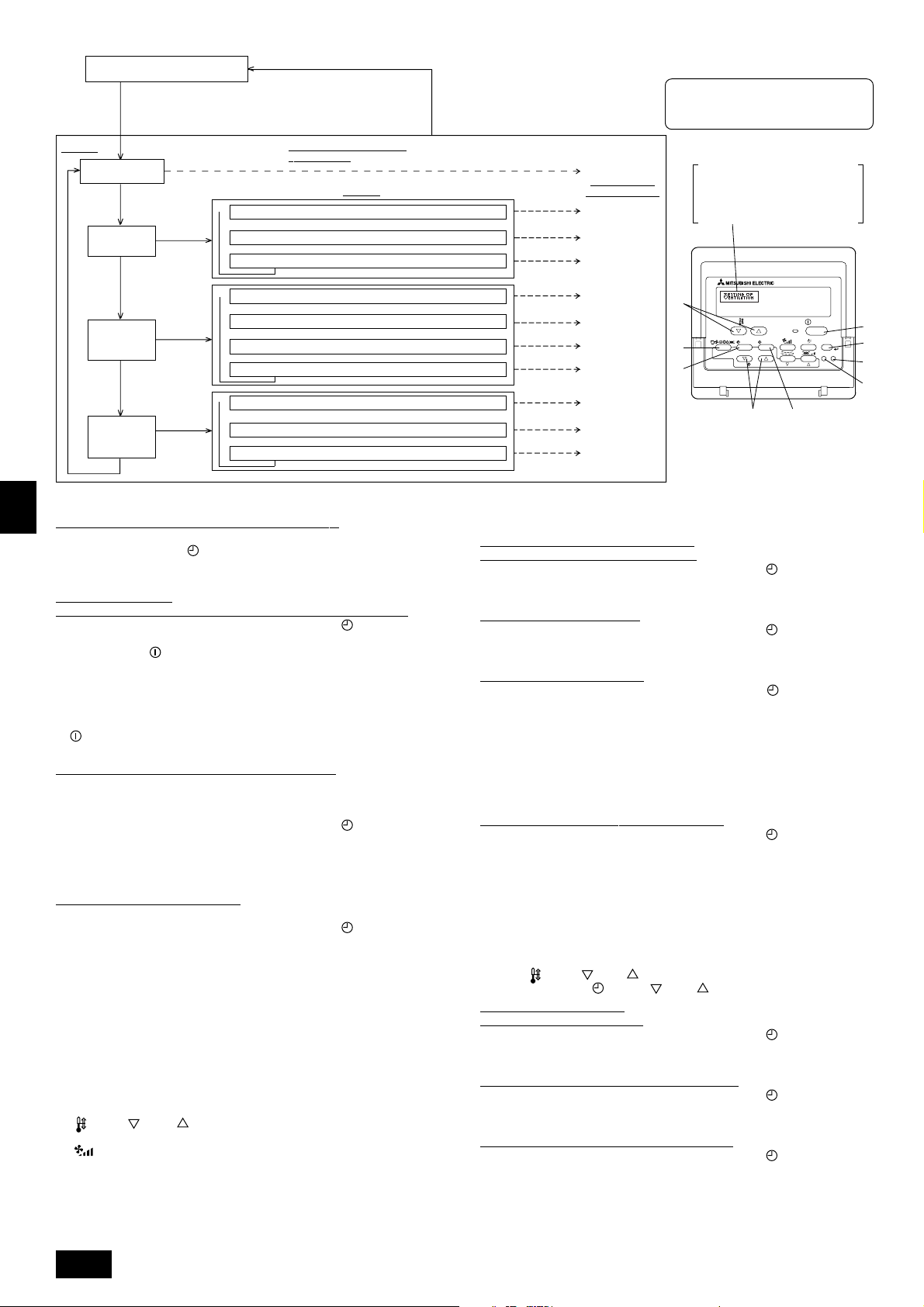
GB
PAR-21MAA
ON/OFF
FILTER
CHECK
OPERATION
CLEAR
TEST
TEMP.
MENU
BACK DAY
MONITOR/SET
CLOCK
ON/OFF
F
G
C
D
B
I
A
H
E
Normalbetriebsanzeige (Anzeige
bei deaktivierter Klimaanlage)
(Halten Sie die Taste E gedrückt und drücken Sie Taste
zwei Sekunden lang.)
* Die Anzeige lässt sich während der Funktionsauswahl,
des Testlaufs und der Selbstdiagnose nicht ändern.
Eintrag 1
Sprache ändern
(“CHANGE LANGUAGE”)
Drücken Sie
Taste E.
Funktionsgrenzen
(“Funktion
auswahlen”)
Drücken Sie
Taste E.
Drücken Sie
Taste E.
Auswahl der
Betriebsart
(“Betriebsart
wahlen”)
Drücken Sie
Taste E.
Änderung der
Anzeige
(“Anzeige
betriebsart”)
Drücken Sie Taste G.
→
Drücken Sie
Taste G.
→
Drücken Sie
Taste G.
Drücken Sie
Taste G.
→ Temperatureinstellung in °C/°F (“Wechsel °C/°F”)
D
Funktionsauswahlmodus der
Fernbedienung
Eintrag 2
Einstellung der Funktionsgrenzen bei der Bedienung (“Sperr-Funktion”)
→
Einstellung der Benutzung der Betriebsart Automatisch (“Auswahl autobetrieb”)
→
Einstellung der Temperaturgrenzen (“Limit temp Funktion”)
Haupt-/Nebenfunktion der Fernbedienung (“Haupt/Neben controller”)
Benutzung der Uhreinstellung (“Uhr”)
Einstellung der Timer-Funktion (“Wochenzeit schalt uhr”)
Kontaktnummer für den Fall von Fehlfunktionen (“CALL.”)
Einstellung der Anzeige der Luftansaugtemperatur (“Raum TEMP gewahlt”)
→→→→→
Einstellung der automatischen Kühl-/Heizanzeige (“Auto Betrieb C/H”)
(Halten Sie die Taste E gedrückt und drükken Sie Taste D zwei Sekunden lang.)
* Die Fernbedienung speichert die
vorgenommenen Änderungen.
Drücken Sie Taste G.
Drücken Sie Taste G.
Drücken Sie Taste G.
Drücken Sie
Taste D.
Drücken Sie
Taste D.
Drücken Sie
Taste D.
Siehe [4]-1
Eintrag 3 (Inhalt
der Einstellungen)
Siehe [4]-2. (1)
Siehe [4]-2. (2)
Siehe [4]-2. (3)
Siehe [4]-3. (1)
Siehe [4]-3. (2)
Siehe [4]-3. (3)
Siehe [4]-3. (4)
Siehe [4]-4. (1)
Siehe [4]-4. (2)
Siehe [4]-4. (3)
HINWEIS
Der Timer-Betrieb stoppt, wenn die Anzeige des
Funktionsauswahlmodus auf die Normalbetriebsanzeige umschaltet.
Punktmatrixanzeige
Die mit CHANGE LANGUAGE
(Sprache einstellen) eingestellte
Sprache wird hier angezeigt. In den
Darstellungen dieser Anleitung ist
Englisch ausgewählt.
[Genaue Einstellung]
D
[4] -1. Einstellung CHANGE LANGUAGE (Sprache ändern)
Die Sprache des Punktmatrix-Displays kann eingestellt werden.
• Drücken Sie die Taste [
MENU], um die Sprache einzustellen.
1 Japanisch (JP), 2 Englisch (GB), 3 Deutsch (D), 4 Spanisch (E),
5 Russisch (RU), 6 Italienisch (I), 7 Chinesisch (CH), 8 Französisch (F)
[4] -2. Funktionsgrenzen
F
(1) Einstellung der Funktionsgrenzen bei der Bedienung (Operation Lock)
• Zur Umschaltung der Einstellung drücken Sie die Taste [
ON/OFF].
1 no1: Die Einstellung der Bedienungssperre (Operation Lock) gilt für alle Tasten
außer der [
ON/OFF]-Taste.
2 no2: Die Einstellung der Bedienungssperre gilt für alle Tasten.
3 OFF (Anfängliche Einstellungswert) :
Die Einstellung der Bedienungssperre wird nicht vorgenommen.
* Damit die Bedienungssperre (Operation Lock) in der normalen Anzeige gültig ist
NL
(müssen Sie die [FILTER]-Taste gedrückt halten und währenddessen die Taste
[
ON/OFF] zwei Sekunden lang drücken) nachdem Sie die obige Einstellung
durchgeführt haben.
(2) Einstellung der Benutzung der Betriebsart Automatisch
Wenn die Fernbedienung an einem Anlage angeschlossen ist, bei dem ein automatischer Betrieb möglich ist, können die folgenden Einstellungen vorgenommen
werden.
SWI
• Zur Umschaltung der Einstellung drücken Sie die Taste [
ON/OFF].
1 ON (Anfängliche Einstellungswert):
Die Betriebsart Automatisch wird angezeigt, wenn diese Betriebsart ausgewählt wird.
2 OFF:
Die Betriebsart Automatisch wird nicht angezeigt, wenn diese Betriebsart ausgewählt wird.
(3) Einstellung der Temperaturgrenzen
Nach dieser Einstellung kann die Temperatur im eingestellten Bereich verändert werden.
• Zur Umschaltung der Einstellung drücken Sie die Taste [ ON/OFF].
1 Limit Kuhl Temp:
Der Temperaturbereich kann in der Betriebsart Kühlen/Trocknen geändert werden.
2 Limit Heiz Temp:
Der Temperaturbereich kann in der Betriebsart Heizen geändert werden.
3 Limit Auto Temp:
E
Der Temperaturbereich kann in der Betriebsart Automatisch geändert werden.
4 OFF (Anfangseinstellung):
Die Temperaturbereichsgrenzen sind nicht aktiv.
* Wenn eine andere Einstellung als OFF gewählt wird, werden die Temperatur-
bereichsgrenzen für Kühlen, Heizen und automatischen Betrieb gleichzeitig eingestellt. Der Bereich kann jedoch nicht begrenzt werden, wenn der eingestellte
Temperaturbereich sich nicht geändert hat.
P
• Um die Temperatur zu erhöhen oder zu verringern, drücken Sie die Taste
[
TEMP ( ) oder ( )].
• Um die Obergrenze und die Untergrenze einzustellen, drücken Sie die Taste
[
] (Gebläsegeschwindigkeit). Die ausgewählte Einstellung blinkt, und die
Temperatur kann eingestellt werden.
• Einstellbarer Bereich
Betriebsart Kühlen/Trocknen: Untergrenze: 19°C bis 30°C Obergrenze: 30°C bis 19°C
Betriebsart Heizen: Untergrenze: 17°C bis 28°C Obergrenze: 28°C bis 17°C
Betriebsart Automatisch: Untergrenze: 19°C bis 28°C Obergrenze: 28°C bis 19°C
26
* Der einstellbare Bereich hängt vom angeschlossenen Anlage ab (Mr.-Slim-An-
lage, Free-Plan-Anlage und Zwischentemperaturanlage)
[4] -3. Einstellen der Auswahl der Betriebsart
(1) Haupt-/Nebenfunktion der Fernbedienung
• Zur Umschaltung der Einstellung drücken Sie die Taste [
ON/OFF].
1 Haupt: Die Fernbedienung fungiert als Hauptfernbedienung.
2 Neben: Die Fernbedienung fungiert als Nebenfernbedienung.
(2) Benutzung der Uhreinstellung
• Zur Umschaltung der Einstellung drücken Sie die Taste [
ON/OFF].
1 ON : Die Clock-Funktion kann benutzt werden.
2 OFF : Die Clock-Funktion kann nicht benutzt werden.
(3) Einstellung der Timer-Funktion
• Zur Umschaltung der Einstellung drücken Sie die Taste [
ON/OFF] (Wählen
Sie einen der folgenden Einträge aus.).
1 Wochenzeit schalt uhr (Anfängliche Einstellungswert):
Der Wochen-Timer kann benutzt werden.
2 Auto Zeit funktion Aus: Der Auto-Off-Timer kann benutzt werden.
3 Einfnche zeit funktion: Der einfache Timer kann benutzt werden.
4 Zeitschaltuhr Aus: Der Timer-Modus kann nicht benutzt werden.
* Wenn die Verwendung der Clock-Einstellung auf OFF steht, kann “Wochenzeit
schalt uhr” nicht benutzt werden.
(4) Kontaktnummer für den Fall von Fehlfunktionen
• Zur Umschaltung der Einstellung drücken Sie die Taste [
ON/OFF].
1 CALL OFF : Die eingestellten Kontaktnummern werden im Falle von
Fehlfunktionen nicht angezeigt.
2 CALL **** *** **** : Die eingestellten Kontaktnummern werden im Falle von
Fehlfunktionen angezeigt.
CALL_ : Die Kontaktnummer kann eingegeben werden, wenn das
Display so aussieht wie links gezeigt.
• Eingabe der Kontaktnummern
Zur Eingabe der Kontaktnummern gehen Sie wie folgt vor.
Bewegen Sie den blinkenden Cursor auf die eingestellten Nummern. Drücken Sie
die Taste [
Drücken Sie die Taste [
TEMP. ( ) Und ( )] um den Cursor nach rechts (links) zu bewegen.
CLOCK ( ) Und ( )] um die Nummern einzustellen.
[4] -4. Einstellung der Anzeige
(1) Temperatureinstellung in °C/°F
• Zur Umschaltung der Einstellung drücken Sie die Taste [
ON/OFF].
1 °C: Für die Temperatur wird die Anlage Celsius (°C) verwendet.
2 °F: Für die Temperatur wird die Anlage Fahrenheit (°F) verwendet.
(2) Einstellung der Anzeige der Luftansaugtemperatur
• Zur Umschaltung der Einstellung drücken Sie die Taste [
ON/OFF].
1 ON: Die Temperatur der Ansaugluft wird angezeigt.
2 OFF: Die Temperatur der Ansaugluft wird nicht angezeigt.
(3) Einstellung der automatischen Kühl-/Heizanzeige
• Zur Umschaltung der Einstellung drücken Sie die Taste [
1 ON:
Entweder “Automatic cooling” (Automatisches Kühlen) oder “Automatic heating”
ON/OFF].
(Automatisches Heizen) wird in der Betriebsart Automatisch angezeigt.
2 OFF: Nur “Automatic” wird in der Betriebsart Automatisch angezeigt.
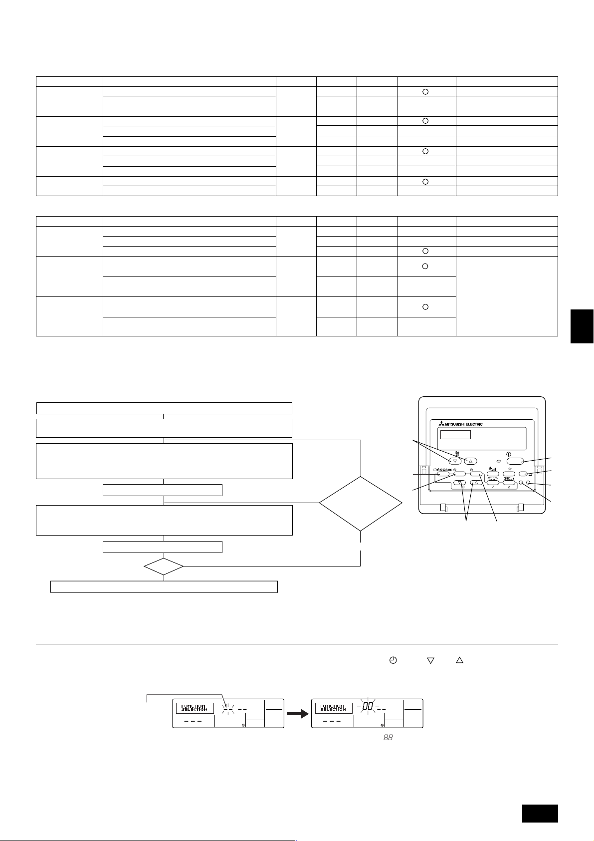
(2) Anlagenfunktionsauswahl
Stellen Sie bitte bei Bedarf die Funktionen jeder Anlage von der Fernbedienung aus ein. Die Funktion jeder Anlage kann nur von der Fernbedienung aus gewählt werden.
Stellen Sie die Funktionen durch Wahl der notwendigen Positionen aus Tabelle 1 und Tabelle 2 ein. (Standardeinstellungen sind unten ebenfalls dargestellt.)
Tabelle 1. In Einzelpunkten aufgeführte Funktionen des gesamten Kältemittelsystems (wählen Sie Anlage Nummer 00 bis 15)
Funktion
Automatische
Wiederherstellung
nach Netzstromausfall
Erkennung der
Innentemperatur
LOSSNAYVerbindung
Netzstrom
Einstellungen
Nicht verfügbar
Verfügbar
Betriebsdurchschnitt der Anlage
Einstellung durch Fernbedienung der Anlage
Interner Sensor der Fernbedienung
Nicht unterstützt
Unterstützt (Anlage nicht mit Außen-Lufteinlaß ausgestattet)
Unterstützt (Anlage mit Außen-Lufteinlaß ausgestattet)
240 V
220 V, 230 V
Betriebsart Nr.
01
02 2
03 2
04
Einstellung Nr.
1
2
1
3
1
3
1
2
Prüfen
Standardeinstellungen
Etwa 4 Minuten nach dem Wiederherstellen des Netzstroms warten.
Bemerkungen
Tabelle 2. In Einzelpunkten aufgeführte Funktionen der Anlage (wählen Sie die Anlagenummern 01 bis 04 oder AL)
Funktion
Filterzeichen
Gebläsebetrieb bei
Thermo aus im
Heizbetrieb
Gebläsebetrieb
während ausgeschalteter Heizung
im Kühlbetrieb
Einstellungen
100 Std.
2500 Std.
Keine Filterzeichenanzeige
Betrieb
Stop
Betrieb
Stop
Betriebsart Nr.
07 2
25
27
Einstellung Nr.
1
3
3
2
1
2
Prüfen
Standardeinstellungen
Beim Wählen des Gebläsebetriebs
“Stopp” stellen Sie die Einstellnummer von Betriebsart Nr. “02” in
Tabelle 1 to “3”. Stellen Sie sicher,
daß sich die Fernbedienung innerhalb des zu klimatisierenden Raums
befindet, so daß sie die Raumtemperatur überwachen kann.
Bemerkungen
Hinweis:
Wenn die Funktionen der Innenanlage nach abgeschlossener Installation mit der Funktionswahl geändert worden sind, geben Sie stets durch Eingabe von 嘷
oder einer anderen Kennzeichnung im zugehörigen Prüffeld von Tabelle 1 oder Tabelle 2 den Inhalt der Einstellungen an.
[Funktion Auswahlablauf]
Sehen Sie sich zuerst den Funktionsablauf an. Als Beispiel wird nachfolgend die Einstellung der “Netzstrom” in Tabelle 1 gezeigt.
(Den aktuellen Einstellvorgang sehen Sie in [Einstellverfahren] 1 bis 0.)
1 Prüfung der Inhalte der Funktionsauswahl.
2 Schalten Sie in den FUNKTIONSAUSWAHL-Betrieb.
(Drücken Sie gleichzeitig im AUS-Status der Fernbedienung die Tasten A und B.)
F
3
Kühlsystemadresse angegeben → 00 (Außenanlagenangabe)
(Nicht notwendig bei einem Kühlsystem.)
4
Anlagen-Adressennummer angegeben → 00 (Innenanlagenangabe)
(Tasten C und D -Betrieb)
5 Anmeldung (Taste E drücken.)
(Angegebene Innenanlage→
Ventilatorbetrieb)
6 Auswahl Betriebsnummer → 04 (Netzstrom)
7 Einstellung Betriebsnummer → 2 (220V, 230V)
(Tasten
F
und G -Betrieb)
NEIN
JA
Kühlsystemadresseund AnlagenAdressennummer
ändern?
E
G
TEMP.
MENU
BACK DAY
MONITOR/SET
PAR-21MAA
C
CLOCK
ON/OFF
OPERATION
D
ON/OFF
FILTER
CHECK
CLEAR
TEST
GB
D
F
I
A
B
H
NL
SWI
8 Anmeldung (Taste E drücken.)
Ende?
NEIN
9
JA
0 Anzeige Abschlußfunktion (Tasten A und B gleichzeitig drücken.)
[Verfahren] (Nur einstellen, wenn Änderung nötig.)
1 Einstellungen für jeden Betrieb prüfen. Wurden Einstellungen einer Betriebsart mit der Funktionsauswahl geändert, ändern sich auch die Funktionen dieser Betriebsart.
Überprüfen Sie den Inhalt der Einstellungen wie in den Schritten 2 bis 7 beschrieben, und ändern Sie die Einstellungen gemäß Eingaben in Tabelle 1 und Tabelle 2.
(Beachten Sie bei Änderung der Einstellung die Standardeinstellungen.)
2 Fernbedienung AUS schalten.
Drücken und halten Sie die Tasten A [FILTER] und B [TEST] gleichzeitig für
zwei Sekunden oder länger.
“Funktion sauswahl” blinkt für einige Zeit. Dann zeigt die Anzeige der Fernbe-
dienung die nachfolgend zu sehenden Änderungen.
Anzeige Kühlsystem-Adresse
3 Außenanlagen-Kühlsystemadressennummer einstellen.
Werden die Tasten C [
CLOCK ( ) und ( )] gedrückt, erhöht oder verringert sich die Kühlsystem-Adressennunmmer zwischen 00 und 15. Stellen Sie
die Kühlsystem-Adressennummer ein, deren Funktion Sie wählen möchten.
(Dieser Schritt ist bei einem Kühlsystem nicht notwendig.)
* Schaltet die Fernbedienung in den AUS-Betrieb, nachdem “Funktion sauswahl” und Raumtemperaturanzeige “ ” für zwei Sekunden geblinkt haben, ist die Kommuni-
kation möglicherweise unnormal. Prüfen Sie, ob in der Nähe der Übertragungskabel Störfrequenzen auftreten.
Hinweis:
Sollte während des Vorgangs ein Fehler auftreten, beenden Sie die Funktionswahl mit Schritt
??
? und wiederholen Sie den Vorgang ab Schritt
??
22
2.
22
27
E
P
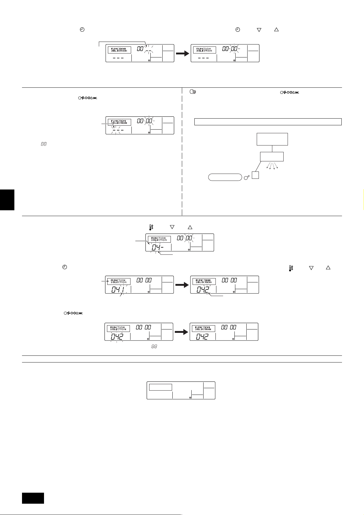
4 Innenanlagen-Adressennummer einstellen.
Drücken Sie die Taste D [
nummer “– –” blinkt.
Anzeige Anlagen-Adressennummer
* Stellen Sie die Betriebsart 01 bis 04 ein, stellen Sie die Anlagen-Adressennummer auf “00”.
* Wenn die Betriebsarten 07, 25, 27 eingestellt werden:
• Bei Einstellung der Funktionen für eine Anlage in einem unabhängigen System stellen Sie bitte die Nummer der Anlage auf 01.
5 Anmeldung der Kühlsystemadresse und Anlagen-Adressennummer
Drücken Sie die Taste E [
adressennummer sind angemeldet.
Nach einiger Zeit blinkt die Anzeige der Betriebsnummer “– –” blinkt.
Betriebsnummer anzeigen
* Blinkt “ ” in der Anzeige der Raumtemperatur, ist die angewählte Kühlsystem-
adresse nicht im System.
Wird “F” in der Anzeige der Anlagen-Adressennummer angezeigt, und blinkt sie
zusammen mit der Anzeige der Kühlsystemadresse, besteht die gewählte An-
GB
lagen-Adressennummer nicht. Korrigieren Sie die Adresse des Kühlsystems
und die Nummer der Anlagenadresse, indem Sie die Schritte 2 und 3 wiederholen.
D
6 Auswahl Betriebsnummer
Stellen Sie die gewünschte Betriebsnummer mit den Tasten F [
ON/OFF]. Die Anzeige der Anlagen-Adressen-
]. Die Kühlsystemadresse- und Anlagen-
TEMP. ( ) und ( )] ein. (Es können nur einstellbare Betriebsnummern gewählt werden.)
Werden die Tasten C [ CLOCK ( ) und ( )] gedrückt, ändert sich die AnlagenAdressennummer in der Reihenfolge in 00 → 01 → 02 → 03 → 04 → AL. Stellen Sie die
Anlagen-Adressennummer der Innenanlage ein, deren Funktionen Sie einstellen möchten.
Erfolgte eine Registrierung mit der Taste E [ ] , startet die angemeldete Innenanlage den Ventilatorbetrieb. Möchten Sie den Standort der Innenanlagen mit der Anlagen-Adressennummer, deren Funktionen Sie gewählt haben,
wissen, prüfen Sie hier. Lauten die Anlagenadressennummer n 00 oder AL, starten alle Innenanlagen der gewählten Kühlsystemadressen den Ventilatorbetrieb.
Ex) Lautet die Kühlsystemadresse 00, ist die Anlagen-Adressennummer = 01 angemeldet
Anmeldung
* Wenn eine Gruppe mit unterschiedlichen Kühlsystemen und eine andere Innen-
anlage als die angegebene Kühlsystemadresse den Ventilatorbetrieb startet,
ist die eingestellte Kühlsystemadresse möglicherweise dupliziert worden.
Überprüfen Sie noch einmal die Kältemitteladresse auf den DIP-Schaltern der
Außenanlage.
Kühlsystemadresse = 00
Innenseitige
Fernbedienung
Außenseitige
AnlagenAdressennummer 01
Ventilatorbetrieb
F
7 Wählen Sie die Einstellungen im Einstellbetrieb.
Wird die Taste G [
hier den Inhalt der aktuellen Einstellung prüfen.
NL
8 Die Einstellungen der Schritte 3 bis 7 sind angemeldet.
Wird die Taste E [
Einstellnummern zu einer ständigen Anzeige, ist die Einstellung beendet.
SWI
* Erscheint “– –” als Betriebs- und Einstellungsnummer und blinkt “
Prüfen Sie, ob in der Nähe der Übertragungskabel Störfrequenzen auftreten.
9 Zur Wahl weiterer Funktionen wiederholen Sie die Schritte 3 bis 8.
0 Auswahl Abschlußfunktion
Drücken und halten Sie die Tasten A [FILTER] und B [TEST] gleichzeitig für zwei Sekunden oder länger.
Nach einiger Zeit wird die Funktionsauswahl-Anzeige gelöscht und die Fernbedienung schaltet in die Aus-Anzeige der Klimaanlage zurück.
MENU] gedrückt, blinkt die aktuelle Nummer. Sie können
Anzeige Einstellungsnummer.
Betriebsnummer anzeigen
Betriebsnummer 04 = Netzstrom
Stellen Sie die Einstellungsnummer mit den Tasten F [ TEMP. ( ) und ( ) ] ein.
Einstellungsnr. 1 = 240V
] gedrückt, blinken die Betriebs- und die Einstellungsnummer und die Anmeldung ist beendet. Wechseln die blinkenden Betriebs- und
” in der Anzeige Raumtemperatur, ist die Kommunikation möglicherweise unnormal.
Einstellungsnummer. 2 = 220 V, 230 V
E
* Schalten Sie die Klimaanlage für 30 Sekunden nach dem Beenden der Funktionsauswahl von der Fernbedienung aus nicht ein.
Hinweis:
Wenn die Funktionen einer Innenanlage nach abgeschlossener Installation mit der Funktionswahl geändert worden sind, geben Sie stets durch Eingabe eines
嘷 oder einer anderen Kennzeichnung im zugehörigen Prüffeld von Tabelle 1 oder Tabelle 2 den Inhalt der Einstellungen an.
P
28
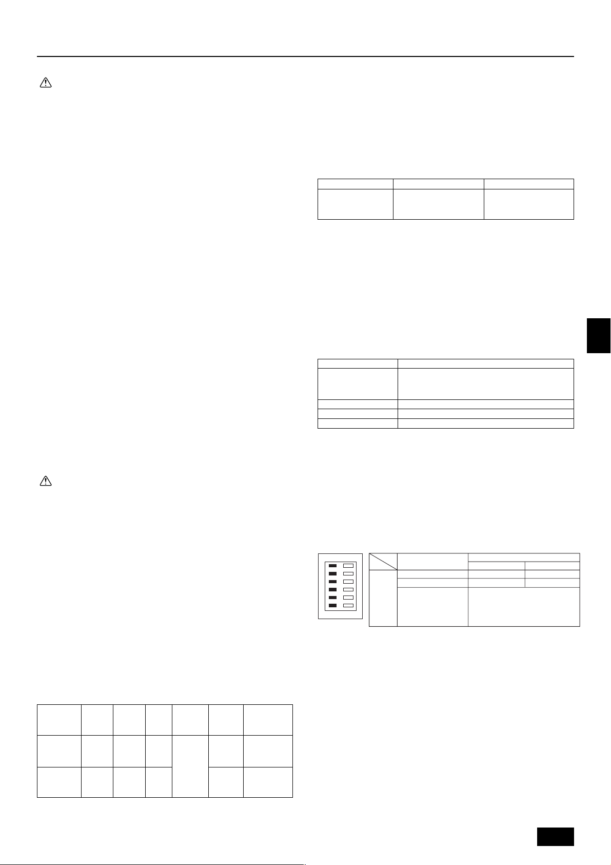
9. Elektroverdrahtung
Vorsichtsmaßnahmen bei der elektrischen Verdrahtung
Warnung:
• Elektroarbeiten sollten nur durch qualifizierte Fachelektriker gemäß ’Engineering Standards for Electrical Installation’ - ’Technische Normen für
Elektroinstallation’ und gemäß Installationshandbüchern vorgenommen
werden. Es sollten auch eigens eingerichtete Stromkreise verwendet werden. Wenn der Stromkreis zu schwach ausgelegt ist oder Installationsfehler aufweist, besteht die Gefahr von Stromschlägen oder Brand.
• Zur Verdrahtung stets die dafür vorgesehenen Kabel verwenden und diese ordnungsgemäß anschließen. Den Anschluß so sichern, daß das Kabel keine äußere Zugspannung auf den Klemmenanschluß ausübt. Bei
fehlerhaftem Anschluß oder wenn das Kabel nicht vollkommen sicher
angebracht ist, kann dies zu Überhitzung oder zu einem Brand führen.
• Darauf achten, die angegebenen Kabel zu verwenden und diese fest anzuschließen, damit keine äußere Zugspannung auf die Klemmenanschlüsse ausgeübt wird. Lose Anschlüsse können Überhitzung oder einen Brand verursachen.
1. Dafür sorgen, daß die Netzstromversorgung über einen gesonderten Strom-
kreis erfolgt.
2. Dafür sorgen, daß ein Erdschlußstromunterbrecher in den Stromkreis instal-
liert wird.
3. Die Anlage so installieren, daß verhindert wird, daß eines der Steuerkreis-
kabel (Fernbedienung) in direkten Kontakt mit dem Netzstromkabel außerhalb
der Anlage gebracht werden kann.
4. Dafür sorgen, daß keiner der Elektroleitungsanschlüsse zu lose gespannt ist
oder einen Wackelkontakt aufweist.
5. Fernbedienungskabel, die oberhalb der Decke angeordnet sind, können Mäuseverbiß ausgesetzt sein. Daher Kabel zum Schutz soweit wie möglich in Metallrohre verlegen.
6. Netzstromkabel niemals an die Zuleitung für die Übertragungskabel anschlie-
ßen, da sonst die Kabel brechen können.
7. Bei Befestigung der Netzstromleitung an den Steuerkasten darauf achten, daß
eine Pufferbuchse gegen Zugspannung angebracht wird (PG-Anschluß oder
ähnliches).
8. Installieren Sie die Anlage so, daß die Kabel für die Fernbedienung und denje-
nigen für das M-NET (MELANS) keine elektrischen Störungen mit dem Netzstromkabel verursachen. (Verlegen Sie nicht beide im gleichen Kreislauf.)
9. Stellen Sie sicher, daß die Anlage ordnungsgemäß geerdet wird.
10. Lassen Sie ausreichend Lose in den Kabeln des Elektrikkastens der Anlage,
da der Kasten bei einigen Wartungsarbeiten entfernt werden muß.
Vorsicht:
• Dafür sorgen, daß die Anlage zur Seite der Außenanlage hin geerdet wird.
Die Erdleitung nicht an Gasrohre, Wasserrohre, Beleuchtungsstäbe oder
Telefonerdleitungen anschließen. Unsachgemäße Erdung kann zu Stromschlägen führen.
• Bestimmte Aufstellorte machen die Installation eines
Erdschlußstromunterbrechers erforderlich. Nichtbeachtung kann zu einem Stromschlag führen.
• Stets einen Erdschlußstromunterbrecher und eine Sicherung der angegebenen Kapazität verwenden. Die Verwendung einer Sicherung mit einer größeren als der angegebenen Kapazität oder die Verwendung eines
Stücks Draht oder von Kupferdraht kann zum Ausfall der Anlage oder zu
einem Brand führen.
• Je nach Aufstellungsort der Anlage ist u.U. ein Fehlstrom-Trennschalter
erforderlich. Wenn kein Fehlstrom-Trennschalter installiert ist, können
Stromschläge entstehen.
• Keine Trennschalter oder Sicherungen verwenden, deren Kapazität von
der richtigen abweicht. Wenn Sicherungen, Leitungsdrähte oder Kupferleitungen mit großer Kapazität verwendet werden, kann dies zu Unfällen
oder Bränden führen.
Die folgende Tabelle ist ein Beispiel. Die Wahl anderer Kapazitäten muß entsprechend den jeweiligen Normen festgelegt werden.
[Verdrahtungsbeispiel] (Für Metallrohrleitung)
PRH-P400MYA
PRH-P500MYA
Netz-
stromkabel
2
16 mm
oder
dicker
2
25 mm
oder
dicker
Unterbrecher
Kapazität
63 A 63 A 0,06 Ω
70 A 70 A 0,04 Ω
Sicherung
Kabel der
Fernbedienung
Kabel oder
Elektroleitung
von 0,3 ~ 1,25
2
(max. DC
mm
12 V)
Erdleitung
16 mm
oder dicker
25 mm
oder dicker
Maximale
permissive
Systemimpedanz *1
2
2
Hinweis:
Dieses Gerät ist ausgelegt auf den Anschluß an eine Netzstromversorgung
*1:
mit einer maximalen Systemimpedanz ZMAX von 0,06
:
PRH-P500 am Übergabepunkt (
des Benutzers.
Der Benutzer muß sicherstellen, daß dieses Gerät nur an eine Stromversorgung angeschlossen wird, die obige Bedingung erfüllt.
Wenn nötig, kann der Benutzer beim Stromversorgungsunternehmen die
Systemimpedanz am Übergabepunkt erfragen.
[Wahl des Erdschlußunterbrechers (NV)]
Bei Wahl eines NF oder NV anstelle der Kombination einer Sicherung der Klasse
B mit einem Schalter wie folgt vorgehen:
Sicherung (Klasse B) 63 A 70 A
Erdschlußunterbrecher
ELB 60 A 75 A
(mit Überlastschutz) 100 mA 0,1s oder weniger 100 mA 0,1s oder weniger
• Die Netzstromkabel für Geräte sollen mindestens dem Entwurf 245 IEC57.
• Bei der Installierung der Klimaanlage ist ein Schalter mit einem Kontaktab-
stand von mindestens 3 mm für jeden Pol vorzusehen.
Beispiel
[Fig. 9.0.1] (P.4)
(1) Normaler Anschluß
(2) Gruppierung (8 Anlagen)
A Netzanschluß B Erdschlussunterbrecher
C Stromunterbrecher oder Trennschalter
D Fernbedienung E Adresse
[Kabel MA-Fernbedienung Anlage] (für Metallrohr)
Kabeltyp
Anzahl der Kabel
Kabeldurchmesser
Gesamtlänge
Wenn das Fernbedienungskabel verlängert wird, soll-
ten die Fernbedienungskabel mindestens 245 IEC53
entsprechen.
Strom
ableitkasten) der Stromversorgung
NV100-SW NV100-SW
NV ist eine Produktbezeichunug von MITSUBISHI
MA-Fernbedienung
2-adriges Kabel
0,3 ~ 1,25 mm
maximal 200 m
Ω
: PRH-P400, 0,04
2
9.1. Einstellung der Adresse
Einstellungen der Anlageadresse
• Setzen Sie bei den Adreßeinstellungen alle DIP-Schalter SW1 (3 ~ 6) auf der
außenseitigen Schalttafel auf <Werkseinstellung: 00, 01>. (Für 1:1)
• Funktionen von SW1 entsprechend der Schaltereinstellung werden unten aufgeführt.
• Zur Steuerung einer Gruppe von Anlagen muß jeder Anlage eine Adresse
zugewiesen werden.
(SW1 der außenseitigen Schalttafel)
OFF ON
1
2
3
4
5
6
[Fig. 9.1.1] (P.5)
1 –
2
Fehleraufzeichnung gelöscht
3 Adresseneinstellung
des Kältemittelsystems
4 ↑
5 ↑
Schaltung der
SW1 Funktion
6 ↑
Modell
Funktionen entsprechend der Schalterstellung
EIN
––
Gelöscht
Anlagenadreßeinstellungen 0 ~ 15
AUS
Normal
9.2. Kabelanschluß
• Verwendung der Rohrleitungshalteplatten
Rohrleitungshalteplatten werden in zwei Größen (ø40, ø52) geliefert. Zum Einsatz kommt die Montageplatte, die dem äußeren Durchmesser der zu verwendenden Elektroleitung entspricht.
[Fig. 9.2.1] (P.5)
A Bei Installation des Schutzrohres von der Bodenplatte
B Bei Installation des Schutzrohres von der Frontplatte
C Befestigungsplatte (angebracht)
D Ausbrechöffnung
Ω
GB
D
F
NL
SWI
E
P
29

10. Installation des Riemens
1. Stellen Sie den Parallelwinkel von Gebläse und Motorriemenscheibe ein wie in
[Fig. 10.0.1] und Tabelle 1 gezeigt.
2. Stellen Sie die Riemenspannung so ein, daß sich der Riemen innerhalb des
Bereichs eindrücken läßt wie in [Fig. 10.0.2] und unten in Tabelle 2 gezeigt.
3. Spannen Sie den Riemen nach, nachdem er ordnungsgemäß auf dem Riemenrad sitzt (nach 24 bis 28 Betriebsstunden).
Wenn ein neuer Riemen verwendet wird, stellen Sie die Spannung etwa auf
das 1,3-fache des maximalen Biegekraft-Werts ein.
4. Spannen Sie den Riemen nach der ersten Einstellung alle 2.000 Stunden.
Tauschen Sie den Riemen aus, wenn er sich um 2 % gelängt hat, die Erstausdehnung (etwa 1 %) eingeschlossen.
(etwa 8.000 Betriebsstunden)
Beim Wählen des Gebläsebetriebs “Stopp” (Betriebsart Nr. 25 “2” in Tabelle 2
von Seite 27), stellen Sie den Riemen alle 1.000 Stunden nach der Feineinstellung nach.
[Fig. 10.0.1] / [Fig. 10.0.2] (P.5)
<A> Parallellauf der Riemenscheibe
<B> Riemenspannung
A Biegekraft (W)
Tabelle 1
Riemenscheibe
Riemenscheibe
Tabelle 2
Riemenscheibe
Ty p
B
Parallelwinkel
Kleinerer Außendurch-
messer (mm)
~ 135
136 ~ 160
161 ~
K (
"
)
10 oder weniger
Biegekraft W
(N)
22 ~ 29
27 ~ 34
29 ~ 37
Abstand von 3 mm pro Meter
GB
11. Änderung der Gebläserichtung (von seitlichen Zufuhr auf Zufuhr von oben)
Bei diesem Gerät kann die Luftzufuhr von seitlicher Zufuhr auf Zufuhr von oben
umgestellt werden.
Modifizierung wie im folgenden beschrieben.
D
[Fig. 11.0.1] (P.5)
A Obere Verkleidung B Abdeckung (Außenseite) C Flansch
D Panel E Gebläse
F Abdeckung (Innenseite)···2 Stk.
F
1 Die obere Verkleidung A, Abdeckung (Außenseite) B, Flansch C, Verklei-
dung D und Abdeckung (Innenseite) F abnehmen. (Schritt 1)
2 Richtung des Gebläses E ändern. (Schritt 2)
Bei Einsatz des Gebläses E in hängender Stellung die Gebläsewelle nicht
anseilen.
3 Obere Verkleidung A, Abdeckung B, Flansch C and Verkleidung D wieder
anbringen. (Schritt 3)
* Zwischen Flansch C, obere Verkleidung A und Schraubfassungen muss für
ausreichende Wasserabdichtung gesorgt werden.
Hinweis:
Bei Luftzufuhr von oben ist die Innenabdeckung
FF
F nicht erforderlich.
FF
Hinweis
12. Testlauf
NL
12.1. Vor dem Testlauf
Der Testlauf kann entweder von der Anlage direkt oder über die Fernbedienung
durchgeführt werden.
1. Prüfliste
• Nach der Verdrahtung der Anlagen prüfen, daß kein Kältemittel austritt, daß
Netzstrom- und Steuerleitungen nicht locker und die Pole nicht umgekehrt
SWI
angeschlossen sind.
• Mit einem Isolationswiderstandsprüfer von 500 V sicherstellen, daß der Widerstand zwischen der Netzklemme und der Erde 1,0 MΩ oder mehr beträgt.
Hat er weniger als 1,0 MΩ, darf die Anlage nicht in Betrieb genommen werden.
• Vergewissern, daß die Anlage keine Fehlfunktion aufweist. (Wenn es eine
Fehlfunktion gibt, können Sie diese mit der LED1 auf der außenseitigen Schalttafel diagnostizieren.)
• Die Netzstromphase überprüfen. Wenn die Phase umgekehrt ist, dreht sich
der Ventilator möglicherweise in der falschen Richtung oder schaltet sich ab.
Auch kann ein unübliches Geräusch erzeugt werden.
• Wenigstens 12 Stunden vor dem Testlauf Strom durch die Kurbelgehäuse-
E
heizung leiten. (Wenn Strom nur für einen kürzeren Zeitraum durchgeleitet
wird, kann dies zu Schäden am Kompressor führen.)
• Bei Modellen, die eine Änderung der Einstellungen für die Wahl von NETZSTROM EIN/AUS-Möglichkeiten erfordern, sachgemäße Änderungen unter
Beachtung der Beschreibung für die Wahl von Funktionen durch die Fernbedienung vornehmen.
Nach Abschluß der oben genannten Prüfungen den Testlauf, wie nachstehend
P
dargestellt, durchführen.
12.2. Testlaufverfahren
1) Fernbedienung
Betriebsabläufe
1 Netzstrom einschalten
Wenn die Anzeige auf der Fernbedienung “
ausgeschaltet. Schalten Sie vor Benutzung der Fernbedienung die Anzeige
“
” aus.
Anzeige “CENTRALLY CONTROLLED”
(ZENTRAL GESTEUERT)
2 Taste [TEST] innerhalb von drei Sekunden zweimal drücken. Der Test
beginnt.
“TEST RUN” (TESTLAUF) und “OPERATION MODE” (BETRIEBSART) wer-
den abwechselnd angezeigt.
3 Die Taste [
Kühlen: Kaltluft wird ausgeblasen.
Heizen: Warmluft wird ausgeblasen (nach einer Weile).
4 Gebläse der außenanlage auf einwandfreien Lauf überprüfen
Die Anlage führt automatische Leistungskontrollen durch, um eine optimale
Geschwindigkeit des außenseitigen Gebläses zu gewährleisten. Das Gebläse
läuft zunächst mit niedriger Geschwindigkeit weiter, um den aktuellen Außenluftbedingungen zu entsprechen, bis es die maximal verfügbare Energie über-
schreitet. Dann kann das Gebläse im Einzelfall anhalten oder je nach Außenluft-
bedingungen in umgekehrter Richtung laufen. Dies ist keine Fehlfunktion.
] drücken
” anzeigt, ist die Fernbedienung
˚C
TEMP.
˚C
ON/OFF
30
 Loading...