

Mitsubishi Electric PQHY-P200-900Y(S)LM-A, PQRY-P200-900Y(S)LM-A Service Manual

PQHY-P200-900Y(S)LM-A
PQRY-P200-900Y(S)LM-A
MODEL

CITY MULTI
MEE15K036
Databook
HEAT SOURCE UNITS
GENERAL LINE-UP
WY SERIES ............................................................................................................................................ 1
WR2 SERIES.......................................................................................................................................... 83
SYSTEM DESIGN
SYSTEM DESIGN WY SERIES ............................................................................................................. 165
SYSTEM DESIGN WR2 SERIES ........................................................................................................... 203
GENERAL LINE-UP
HEAT SOURCE
MEE15K036
I.GENERAL LINE-UP
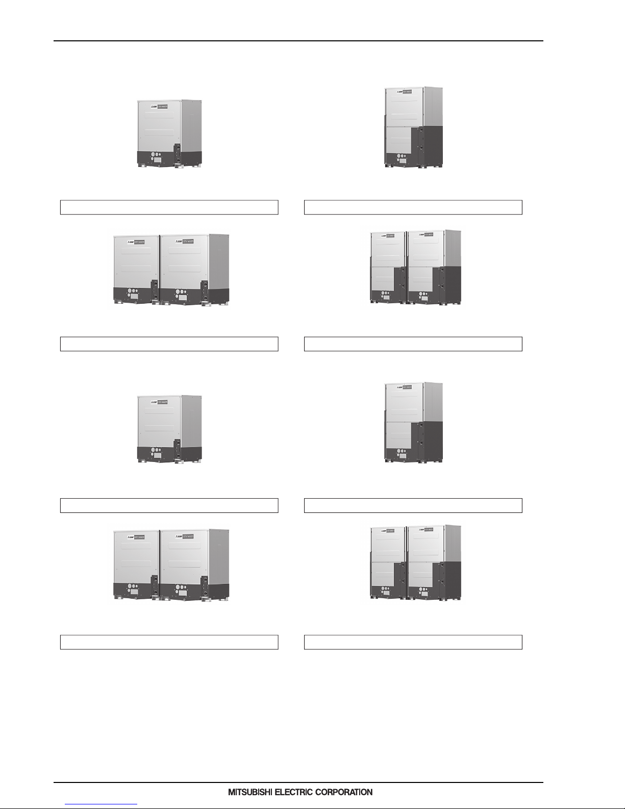
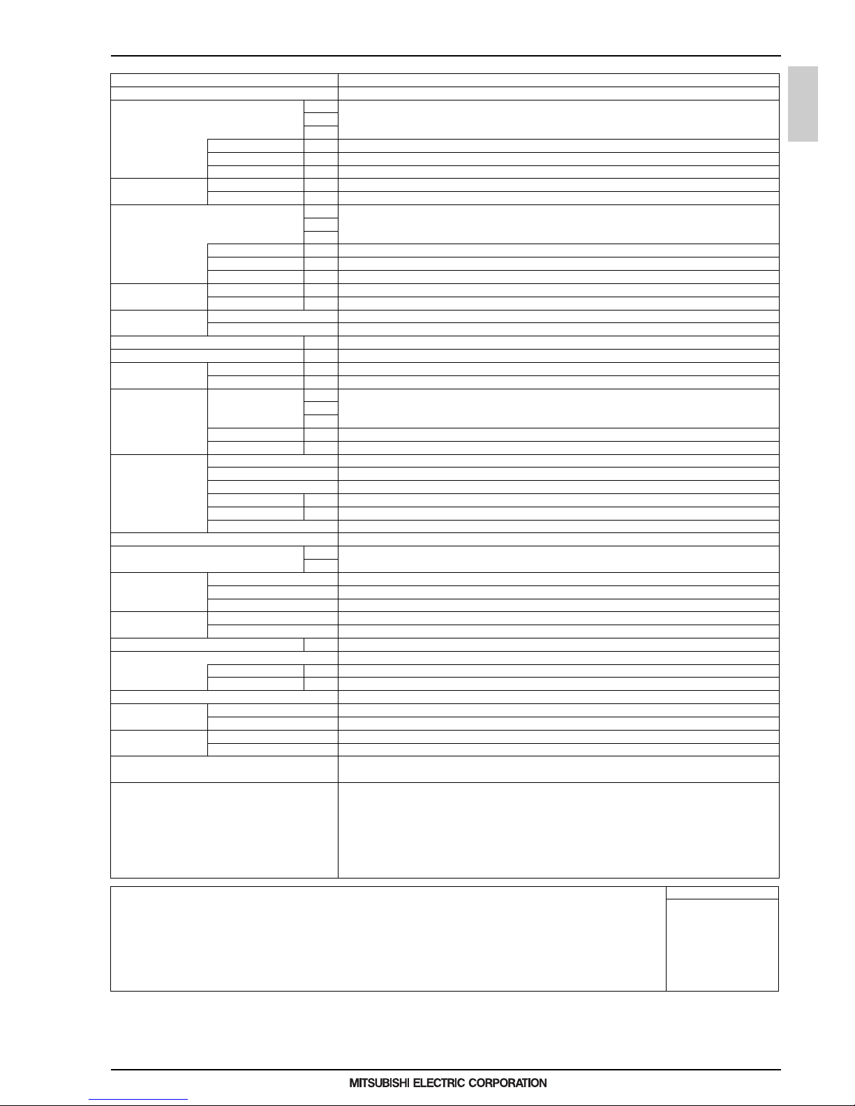
Heat Pump WY Series
16, 18, 20, 22, 24HP
28, 30, 32, 34, 36HP
PQHY-P250YLM-APQHY-P200YLM-A
PQHY-P300YLM-A
PQHY-P400YLM-A
PQHY-P500YLM-A
PQHY-P600YLM-A
PQHY-P350YLM-A
PQHY-P450YLM-A
PQHY-P550YLM-A
PQHY-P450YSLM-A
PQHY-P550YSLM-A
PQHY-P400YSLM-A
PQHY-P500YSLM-A
PQHY-P600YSLM-A
8, 10, 12HP 14, 16, 18, 20, 22, 24HP
PQHY-P750YSLM-A
PQHY-P850YSLM-A
PQHY-P700YSLM-A
PQHY-P800YSLM-A
PQHY-P900YSLM-A
PQRY-P250YLM-APQRY-P200YLM-A
PQRY-P300YLM-A
PQRY-P400YLM-A
PQRY-P500YLM-A
PQRY-P600YLM-A
PQRY-P350YLM-A
PQRY-P450YLM-A
PQRY-P550YLM-A
PQRY-P450YSLM-A
PQRY-P550YSLM-A
PQRY-P400YSLM-A
PQRY-P500YSLM-A
PQRY-P600YSLM-A
PQRY-P750YSLM-A
PQRY-P850YSLM-A
PQRY-P700YSLM-A
PQRY-P800YSLM-A
PQRY-P900YSLM-A
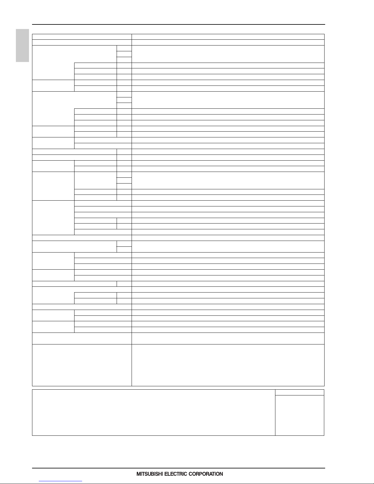
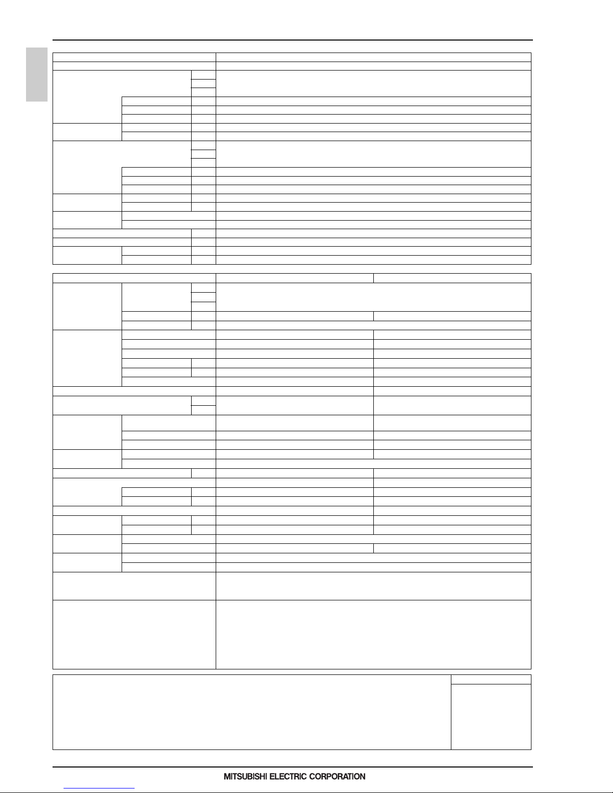
Heat Recovery WR2 Series
16, 18, 20, 22, 24HP
28, 30, 32, 34, 36HP
8, 10, 12HP 14, 16, 18, 20, 22, 24HP

1
WY SERIES
HEAT SOURCE
HEAT SOURCE UNITS
MEE15K036
I.WY SERIES
1. SPECIFICATIONS........................................................................................................................................... 2
2. EXTERNAL DIMENSIONS .............................................................................................................................. 21
3. CENTER OF GRAVITY ................................................................................................................................... 26
4. ELECTRICAL WIRING DIAGRAMS................................................................................................................ 27
5. SOUND LEVELS ............................................................................................................................................. 28
6. OPERATION TEMPERATURE RANGE.......................................................................................................... 33
7. CAPACITY TABLES........................................................................................................................................ 34
7-1. Correction by temperature....................................................................................................................... 34
7-2. Correction by total indoor......................................................................................................................... 53
7-3. Correction by refrigerant piping length..................................................................................................... 60
8. SYSTEM DESIGN GUIDE............................................................................................................................... 64
8-1. Designing of water circuit system ............................................................................................................ 64
8-2. Water piping work .................................................................................................................................... 76
9. OPTIONAL PARTS.......................................................................................................................................... 80
9-1. JOINT ...................................................................................................................................................... 80
9-2. HEADER.................................................................................................................................................. 81
9-3. OUTDOOR TWINNING KIT..................................................................................................................... 82

2
WY
MEE15K036
1. SPECIFICATIONS
HEAT SOURCE
I.WY SERIES1. SPECIFICATIONS
Model PQHY-P200YLM-A
Power source 3-phase 4-wire 380-400-415 V 50/60 Hz
Cooling capacity *1 kW 22.4
(Nominal) kcal/h 20,000
*1 BTU/h 76,400
Power input kW 3.71
Current input A 6.2-5.9-5.7
EER kW/kW 6.03
Temp. range of Indoor W.B. 15.0~24.0°C (59~75°F)
cooling Circulating water °C 10.0~45.0°C (50~113°F)
Heating capacity *2 kW 25.0
(Nominal) kcal/h 21,500
*2 BTU/h 85,300
Power input kW 3.97
Current input A 6.7-6.3-6.1
COP kW/kW 6.29
Temp. range of Indoor D.B. 15.0~27.0°C (59~81°F)
heating Circulating water °C 10.0~45.0°C (50~113°F)
Indoor unit Total capacity 50~130% of heat source unit capacity
connectable Model/Quantity P15~P250/1~17
Sound pressure level (measured in anechoic room) dB <A> 46
Sound power level (measured in anechoic room) dB <A> 60
Refrigerant Liquid pipe mm (in.) 9.52 (3/8) Brazed
piping diameter Gas pipe mm (in.) 19.05 (3/4) Brazed
Circulating water Water flow rate m3/h 5.76
L/min 96
cfm 3.4
Pressure drop kPa 24
Operating volume range m3/h 3.0 ~ 7.2
Compressor Type Inverter scroll hermetic compressor
Manufacture AC&R Works, MITSUBISHI ELECTRIC CORPORATION
Starting method Inverter
Motor output kW 4.8
Case heater kW -
Lubricant MEL32
External finish Galvanized steel sheets
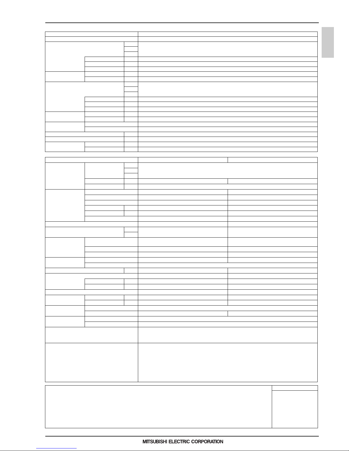
External dimension H x W x D mm 1,100 x 880 x 550
in. 43-5/16 x 34-11/16 x 21-11/16
Protection devices High pressure protection High pressure sensor, High pressure switch at 4.15 MPa (601 psi)
Inverter circuit (COMP.) Over-heat protection, Over-current protection
Compressor Over-heat protection
Refrigerant Type x original charge R410A x 5.0 kg (12 lbs)
Control LEV and HIC circuit
Net weight kg (lbs) 174 (384)
Heat exchanger plate type
Water volume in plate I 5.0
Water pressure Max. MPa 2.0
HIC circuit (HIC: Heat Inter-Changer) Copper pipe, tube-in-tube structure
Drawing External WKS94C746
Wiring WKE94G131
Standard attachment Do cument Installation Manual
Accessory Refrigerant conn. pipe
Optional parts Joint: CMY-Y102SS/LS-G2
Header: CMY-Y104, 108, 1010-G
Remarks Details on foundation work, duct work, insulation work, electrical wiring, power source switch, and other items shall be referred
to the Installation Manual.
Due to continuing improvement, above specifications may be subject to change without notice.
The ambient temperature of the heat source unit needs to be kept below 40°C D.B.
The ambient relative humidity of the heat source unit needs to be kept below 80%.
The heat source unit should not be installed at outdoor.
Be sure to mount a strainer (more than 50 meshes) at the water inlet piping of the unit.
Be sure to provide interlocking for the unit operation and water circuit.
Install the supplied insulation material to the unused drain-socket.
When installing insulation material around both water and refrigerant piping, follow the installation manual.
Notes: Unit converter
1.Nominal cooling conditions (sub ject to JIS B8615-2)
Indoor: 27°CD.B./19°CW.B. (81°FD.B./66°FW.B.), Water temperature: 30°C (86°F)
Pipe length: 7.5 m (24-9/16 ft.), Level difference: 0 m (0 ft.)
2.Nominal heating conditions (subject to JIS B8615-2)
Indoor: 20°CD.B. (68°FD.B.) ,Water temperature: 20°C (68°FD.B.)
Pipe length: 7.5 m (24-9/16 ft.), Level difference: 0 m (0 ft.)
BTU/h =kW x 3,412
cfm =m3/min x 35.31
lbs =kg/0.4536
*Above specification data is
subject to rounding variatio n.

3
WY
MEE15K036
1. SPECIFICATIONS
HEAT SOURCE
Model PQHY-P250YLM-A
Power source 3-phase 4-wire 380-400-415 V 50/60 Hz
Cooling capacity *1 kW 28.0
(Nominal) kcal/h 25,000
*1 BTU/h 95,500
Power input kW 4.90
Current input A 8.2-7.8-7.5
EER kW/kW 5.71
Temp. range of Indoor W. B. 15.0~24.0°C (59~75°F)
cooling Circulating water °C 10.0~45.0°C (50~113°F)
Heating capacity *2 kW 31.5
(Nominal) kcal/h 27,100
*2 BTU/h 107,500
Power input kW 5.08
Current input A 8.5-8.1-7.8
COP kW/kW 6.20
Temp. range of Indoor D.B . 15.0~27.0°C (59~81°F)
heating Circulating water °C 10.0~45.0°C (50~113°F)
Indoor unit Total capacity 50~130% of heat source unit capacity
connectable Model/Quantity P15~P250/1~21
Sound pressure level (measured in anechoic room) dB <A> 48
Sound power level (measured in anechoic room) dB <A> 62
Refrigerant Liquid pipe mm (in.) 9.52 (3/8) Brazed (12.7 (1/2) Brazed, farthest length >= 90 m)
piping diameter Gas pipe mm (in.) 22.2 (7/8) Brazed
Circulating water Water flow rate m3/h 5.76
L/min 96
cfm 3.4
Pressure drop kPa 24
Operating volume range m3/h 3.0 ~ 7.2
Compressor Type Inverter scroll hermetic compressor
Manufacture AC&R Works, MITSUBISHI ELECTRIC CORPORATION
Starting method Inverter
Motor output kW 6.2
Case heater kW -
Lubricant MEL32
External finish Galvanized steel sheets
External dimension H x W x D mm 1,100 x 880 x 550
in. 43-5/16 x 34-11/16 x 21 -11/16
Protection devices High pressure protection High pressure sensor, High pressure swit ch at 4.15 MPa (601 psi)
Inverter circuit (COMP.) Over-heat protection, Over-current protection
Compressor Over-heat protection
Refrigerant Type x original charge R410A x 5.0 kg (12 lbs)
Control LEV and HIC circuit
Net weight kg (lbs) 174 (384)
Heat exchanger plate t ype
Water volume in plate I 5.0
Water pressure Max. MPa 2.0
HIC circuit (HIC: Heat Inter-Changer) Copper pipe, tube-in-tube structure
Drawing External WK S94C746
Wiring WKE94G131
Standard attachment Document Installation Manual
Accessory Refrigerant conn. pipe
Optional parts Joint: CMY-Y102SS/LS-G2
Header: CMY-Y104, 108, 1010-G
Remarks Details on foundation work, duct work, insulation work, electrical wiring, po wer source switch, and other items shall be referred
to the Installation Manual.
Due to continuing improvement, above specifications may be subject to change without notice.
The ambient temperature of the heat source unit needs to be kept below 40°C D.B.
The ambient relative humidity of the heat source unit needs to be kept below 80%.
The heat source unit should not be installed at outdoor.
Be sure to mount a strainer (more than 50 meshes) at the water inlet piping of the unit.
Be sure to provide interlocking for the unit operation and water circuit.
Install the supplied insulation ma terial to the unused drain-socket.
When installing insulation material around both water and refrigerant piping, follow the installation manual.
Notes: Unit converter
1.Nominal cooling conditions (subject to JIS B8615-2)
Indoor: 27°CD.B./19°CW.B. (81°FD.B./66°FW.B.), Water temperature: 30°C (86°F)
Pipe length: 7.5 m (24-9/16 ft.), Level difference: 0 m (0 ft.)
2.Nominal heating conditions (subject to JIS B8615-2)
Indoor: 20°CD.B. (68°FD.B.) ,Water temperature: 20°C (68°FD.B.)
Pipe length: 7.5 m (24-9/16 ft.), Level difference: 0 m (0 ft.)
BTU/h =kW x 3,412
cfm =m3/min x 35.31
lbs =kg/0.4536
*Above specification data is
subject to rounding variation.

4
WY
MEE15K036
1. SPECIFICATIONS
HEAT SOURCE
Model PQHY-P300YLM-A
Power source 3-phase 4-wire 380-400-415 V 50/60 Hz
Cooling capacity *1 kW 33.5
(Nominal) kcal/h 30,000
*1 BTU/h 114,300
Power input kW 6.04
Current input A 10.1-9.6-9.3
EER kW/kW 5.54
Temp. range of Indoor W.B. 15.0~24.0°C (59~75°F)
cooling Circulating water °C 10.0~45.0°C (50~113°F)
Heating capacity *2 kW 37.5
(Nominal) kcal/h 32,300
*2 BTU/h 128,000
Power input kW 6.25
Current input A 10.5-10.0-9.6
COP kW/kW 6.00
Temp. range of Indoor D.B. 15.0~27.0°C (59~81°F)
heating Circulating water °C 10.0~45.0°C (50~113°F)
Indoor unit Total capacity 50~130% of heat source unit capacity
connectable Model/Quantity P15~P250/1~26
Sound pressure level (measured in anechoic room) dB <A> 54
Sound power level (measured in anechoic room) dB <A> 68
Refrigerant Liquid pipe mm (in.) 9.52 (3/8) Brazed (12.7 (1/2) Brazed, farthest length >= 40 m)
piping diameter Gas pipe mm (in.) 22.2 (7/8) Brazed
Circulating water Water flow rate m3/h 5.76
L/min 96
cfm 3.4
Pressure drop kPa 24
Operating volume range m3/h 3.0 ~ 7.2
Compressor Type Inverter scroll hermetic compressor
Manufacture AC&R Works, MITSUBISHI ELECTRIC CORPORATION
Starting method Inverter
Motor output kW 7.7
Case heater kW -
Lubricant MEL32
External finish Galvanized steel sheets
External dimension H x W x D mm 1,100 x 880 x 550
in. 43-5/16 x 34-11/16 x 21-11/16
Protection devices High pressure protection High pressure sensor, High pressure switch at 4.15 MPa (601 psi)
Inverter circuit (COMP.) Over-heat protection, Over-current protection
Compressor Over-heat protection
Refrigerant Type x original charge R410A x 5.0 kg (12 lbs)
Control LEV and HIC circuit
Net weight kg (lbs) 174 (384)
Heat exchanger plate type
Water volume in plate I 5.0
Water pressure Max. MPa 2.0
HIC circuit (HIC: Heat Inter-Changer) Copper pipe, tube-in-tube structure
Drawing External WKS94C746
Wiring WKE94G131
Standard attachment Do cument Installation Manual
Accessory Refrigerant conn. pipe
Optional parts Joint: CMY-Y102SS/LS-G2
Header: CMY-Y104, 108, 1010-G
Remarks Details on foundation work, duct work, insulation work, electrical wiring, power source switch, and other items shall be referred
to the Installation Manual.
Due to continuing improvement, above specifications may be subject to change without notice.
The ambient temperature of the heat source unit needs to be kept below 40°C D.B.
The ambient relative humidity of the heat source unit needs to be kept below 80%.
The heat source unit should not be installed at outdoor.
Be sure to mount a strainer (more than 50 meshes) at the water inlet piping of the unit.
Be sure to provide interlocking for the unit operation and water circuit.
Install the supplied insulation material to the unused drain-socket.
When installing insulation material around both water and refrigerant piping, follow the installation manual.
Notes: Unit converter
1.Nominal cooling conditions (sub ject to JIS B8615-2)
Indoor: 27°CD.B./19°CW.B. (81°FD.B./66°FW.B.), Water temperature: 30°C (86°F)
Pipe length: 7.5 m (24-9/16 ft.), Level difference: 0 m (0 ft.)
2.Nominal heating conditions (subject to JIS B8615-2)
Indoor: 20°CD.B. (68°FD.B.) ,Water temperature: 20°C (68°FD.B.)
Pipe length: 7.5 m (24-9/16 ft.), Level difference: 0 m (0 ft.)
BTU/h =kW x 3,412
cfm =m3/min x 35.31
lbs =kg/0.4536
*Above specification data is
subject to rounding variatio n.
5
WY
MEE15K036
1. SPECIFICATIONS
HEAT SOURCE
Model PQHY-P350YLM-A
Power source 3-phase 4-wire 380-400-415 V 50/60 Hz
Cooling capacity *1 kW 40.0
(Nominal) kcal/h 35,000
*1 BTU/h 136,500
Power input kW 7.14
Current input A 12.0-11.4-11.0
EER kW/kW 5.60
Temp. range of Indoor W. B. 15.0~24.0°C (59~75°F)
cooling Circulating water °C 10.0~45.0°C (50~113°F)
Heating capacity *2 kW 45.0
(Nominal) kcal/h 40,000
*2 BTU/h 153,500
Power input kW 7.53
Current input A 12.7-12.0-11.6
COP kW/kW 5.97
Temp. range of Indoor D.B . 15.0~27.0°C (59~81°F)
heating Circulating water °C 10.0~45.0°C (50~113°F)
Indoor unit Total capacity 50~130% of heat source unit capacity
connectable Model/Quantity P15~P250/1~30
Sound pressure level (measured in anechoic room) dB <A> 52
Sound power level (measured in anechoic room) dB <A> 66
Refrigerant Liquid pipe mm (in.) 12.7 (1/2) Brazed
piping diameter Gas pipe mm (in.) 28.58 (1-1/8) Brazed
Circulating water Water flow rate m3/h 7.20
L/min 120
cfm 4.2
Pressure drop kPa 44
Operating volume range m3/h 4.5 ~ 11. 6
Compressor Type Inverter scroll hermetic compressor
Manufacture AC&R Works, MITSUBISHI ELECTRIC CORPORATION
Starting method Inverter
Motor output kW 9.5
Case heater kW -
Lubricant MEL32
External finish Galvanized steel sheets
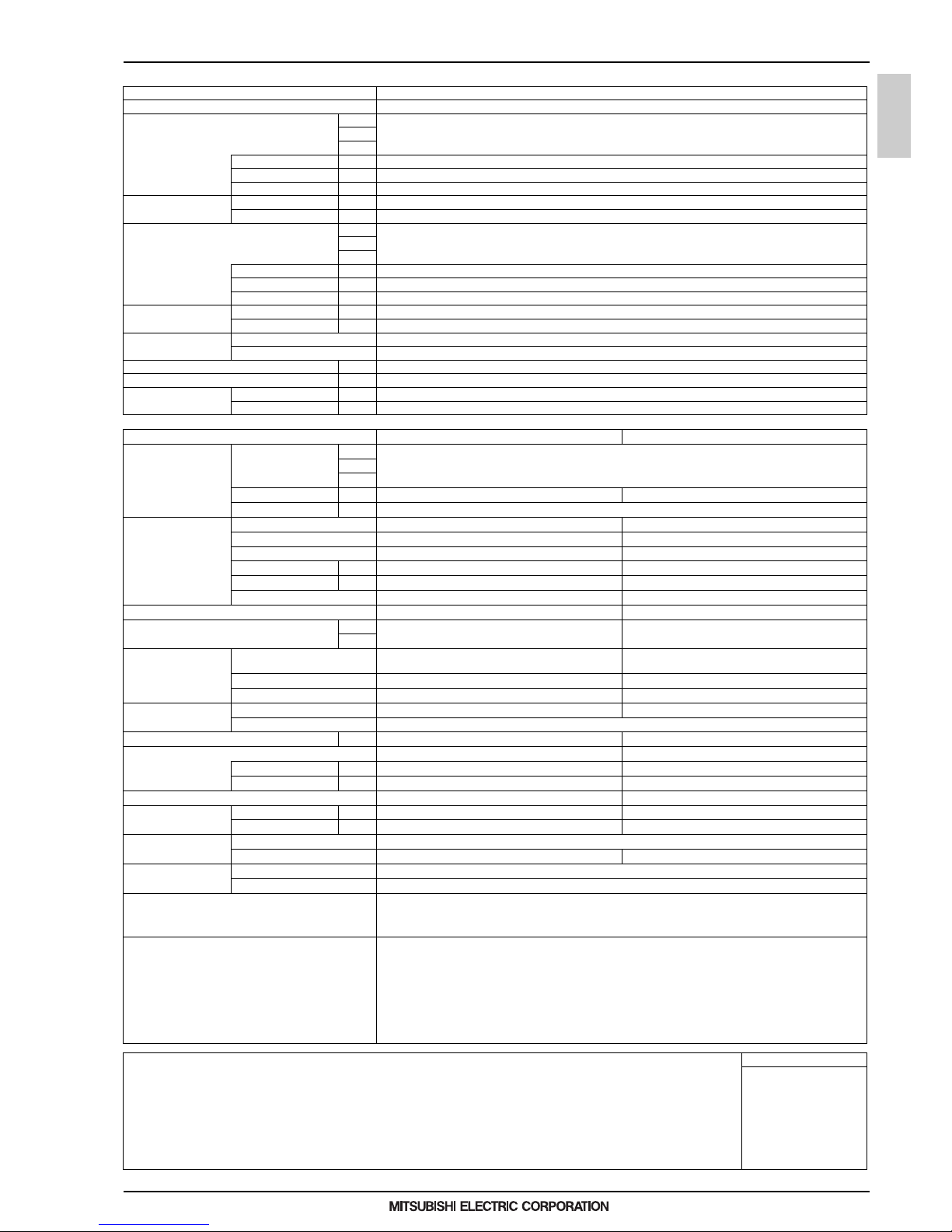
External dimension H x W x D mm 1,450 x 880 x 550
in. 57-1 /8 x 34-11/16 x 21-11/16
Protection devices High pressure protection High pressure sensor, High pressure swit ch at 4.15 MPa (601 psi)
Inverter circuit (COMP.) Over-heat protection, Over-current protection
Compressor Over-heat protection
Refrigerant Type x original charge R410A x 6.0 kg (14 lbs)
Control LEV and HIC circuit
Net weight kg (lbs) 217 (479)
Heat exchanger plate t ype
Water volume in plate I 5.0
Water pressure Max. MPa 2.0
HIC circuit (HIC: Heat Inter-Changer) Copper pipe, tube-in-tube structure
Drawing External WK S94C747
Wiring WKE94G131
Standard attachment Document Installation Manual
Accessory Refrigerant conn. pipe
Optional parts Joint: CMY-Y102SS/LS-G2, CMY-Y202S-G2
Header: CMY-Y104, 108, 1010-G
Remarks Details on foundation work, duct work, insulation work, electrical wiring, po wer source switch, and other items shall be referred
to the Installation Manual.
Due to continuing improvement, above specifications may be subject to change without notice.
The ambient temperature of the heat source unit needs to be kept below 40°C D.B.
The ambient relative humidity of the heat source unit needs to be kept below 80%.
The heat source unit should not be installed at outdoor.
Be sure to mount a strainer (more than 50 meshes) at the water inlet piping of the unit.
Be sure to provide interlocking for the unit operation and water circuit.
Install the supplied insulation ma terial to the unused drain-socket.
When installing insulation material around both water and refrigerant piping, follow the installation manual.
Notes: Unit converter
1.Nominal cooling conditions (subject to JIS B8615-2)
Indoor: 27°CD.B./19°CW.B. (81°FD.B./66°FW.B.), Water temperature: 30°C (86°F)
Pipe length: 7.5 m (24-9/16 ft.), Level difference: 0 m (0 ft.)
2.Nominal heating conditions (subject to JIS B8615-2)
Indoor: 20°CD.B. (68°FD.B.) ,Water temperature: 20°C (68°FD.B.)
Pipe length: 7.5 m (24-9/16 ft.), Level difference: 0 m (0 ft.)
BTU/h =kW x 3,412
cfm =m3/min x 35.31
lbs =kg/0.4536
*Above specification data is
subject to rounding variation.
6
WY
MEE15K036
1. SPECIFICATIONS
HEAT SOURCE
Model PQHY-P400YLM-A
Power source 3-phase 4-wire 380-400-415 V 50/60 Hz
Cooling capacity *1 kW 45.0
(Nominal) kcal/h 40,000
*1 BTU/h 153,500
Power input kW 8.03
Current input A 13.5-12.8-12.4
EER kW/kW 5.60
Temp. range of Indoor W.B. 15.0~24.0°C (59~75°F)
cooling Circulating water °C 10.0~45.0°C (50~113°F)
Heating capacity *2 kW 50.0
(Nominal) kcal/h 45,000
*2 BTU/h 170,600
Power input kW 8.37
Current input A 14.1-13.4-12.9
COP kW/kW 5.97
Temp. range of Indoor D.B. 15.0~27.0°C (59~81°F)
heating Circulating water °C 10.0~45.0°C (50~113°F)
Indoor unit Total capacity 50~130% of heat source unit capacity
connectable Model/Quantity P15~P250/1~34
Sound pressure level (measured in anechoic room) dB <A> 52
Sound power level (measured in anechoic room) dB <A> 66
Refrigerant Liquid pipe mm (in.) 15.88 (5/8) Brazed
piping diameter Gas pipe mm (in.) 28.58 (1- 1/8) Brazed
Circulating water Water flow rate m3/h 7.20
L/min 120
cfm 4.2
Pressure drop kPa 44
Operating volume range m3/h 4.5 ~ 11.6
Compressor Type Inverter scroll hermetic compressor
Manufacture AC&R Works, MITSUBISHI ELECTRIC CORPORATION
Starting method Inverter
Motor output kW 10.7
Case heater kW -
Lubricant MEL32
External finish Galvanized steel sheets
External dimension H x W x D mm 1,450 x 880 x 550
in. 57-1/8 x 34-11/16 x 21-11/16
Protection devices High pressure protection High pressure sensor, High pressure switch at 4.15 MPa (601 psi)
Inverter circuit (COMP.) Over-heat protection, Over-current protection
Compressor Over-heat protection
Refrigerant Type x original charge R410A x 6.0 kg (14 lbs)
Control LEV and HIC circuit
Net weight kg (lbs) 217 (479)
Heat exchanger plate type
Water volume in plate I 5.0
Water pressure Max. MPa 2.0
HIC circuit (HIC: Heat Inter-Changer) Copper pipe, tube-in-tube structure
Drawing External WKS94C747
Wiring WKE94G131
Standard attachment Do cument Installation Manual
Accessory Refrigerant conn. pipe
Optional parts Joint: CMY-Y102SS/LS-G2, CMY-Y202S-G2
Header: CMY-Y104, 108, 1010-G
Remarks Details on foundation work, duct work, insulation work, electrical wiring, power source switch, and other items shall be referred
to the Installation Manual.
Due to continuing improvement, above specifications may be subject to change without notice.
The ambient temperature of the heat source unit needs to be kept below 40°C D.B.
The ambient relative humidity of the heat source unit needs to be kept below 80%.
The heat source unit should not be installed at outdoor.
Be sure to mount a strainer (more than 50 meshes) at the water inlet piping of the unit.
Be sure to provide interlocking for the unit operation and water circuit.
Install the supplied insulation material to the unused drain-socket.
When installing insulation material around both water and refrigerant piping, follow the installation manual.
Notes: Unit converter
1.Nominal cooling conditions (sub ject to JIS B8615-2)
Indoor: 27°CD.B./19°CW.B. (81°FD.B./66°FW.B.), Water temperature: 30°C (86°F)
Pipe length: 7.5 m (24-9/16 ft.), Level difference: 0 m (0 ft.)
2.Nominal heating conditions (subject to JIS B8615-2)
Indoor: 20°CD.B. (68°FD.B.) ,Water temperature: 20°C (68°FD.B.)
Pipe length: 7.5 m (24-9/16 ft.), Level difference: 0 m (0 ft.)
BTU/h =kW x 3,412
cfm =m3/min x 35.31
lbs =kg/0.4536
*Above specification data is
subject to rounding variatio n.

7
WY
MEE15K036
1. SPECIFICATIONS
HEAT SOURCE
Model PQHY-P450YLM-A
Power source 3-phase 4-wire 380-400-415 V 50/60 Hz
Cooling capacity *1 kW 50.0
(Nominal) kcal/h 45,000
*1 BTU/h 170,600
Power input kW 9.29
Current input A 15.6-14.8-14.3
EER kW/kW 5.38
Temp. range of Indoor W. B. 15.0~24.0°C (59~75°F)
cooling Circulating water °C 10.0~45.0°C (50~113°F)
Heating capacity *2 kW 56.0
(Nominal) kcal/h 50,000
*2 BTU/h 191,100
Power input kW 9.79
Current input A 16.5-15.7-15.1
COP kW/kW 5.72
Temp. range of Indoor D.B . 15.0~27.0°C (59~81°F)
heating Circulating water °C 10.0~45.0°C (50~113°F)
Indoor unit Total capacity 50~130% of heat source unit capacity
connectable Model/Quantity P15~P250/1~39
Sound pressure level (measured in anechoic room) dB <A> 54
Sound power level (measured in anechoic room) dB <A> 70
Refrigerant Liquid pipe mm (in.) 15.88 (5/8) Brazed
piping diameter Gas pipe mm (in.) 28.58 (1-1/8) Brazed
Circulating water Water flow rate m3/h 7.20
L/min 120
cfm 4.2
Pressure drop kPa 44
Operating volume range m3/h 4.5 ~ 11. 6
Compressor Type Inverter scroll hermetic compressor
Manufacture AC&R Works, MITSUBISHI ELECTRIC CORPORATION
Starting method Inverter
Motor output kW 11.6
Case heater kW -
Lubricant MEL32
External finish Galvanized steel sheets
External dimension H x W x D mm 1,450 x 880 x 550
in. 57-1 /8 x 34-11/16 x 21-11/16
Protection devices High pressure protection High pressure sensor, High pressure swit ch at 4.15 MPa (601 psi)
Inverter circuit (COMP.) Over-heat protection, Over-current protection
Compressor Over-heat protection
Refrigerant Type x original charge R410A x 6.0 kg (14 lbs)
Control LEV and HIC circuit
Net weight kg (lbs) 217 (479)
Heat exchanger plate t ype
Water volume in plate I 5.0
Water pressure Max. MPa 2.0
HIC circuit (HIC: Heat Inter-Changer) Copper pipe, tube-in-tube structure
Drawing External WK S94C747
Wiring WKE94G131
Standard attachment Document Installation Manual
Accessory Refrigerant conn. pipe
Optional parts Joint: CMY-Y102SS/LS-G2, CMY-Y202S-G2
Header: CMY-Y104, 108, 1010-G
Remarks Details on foundation work, duct work, insulation work, electrical wiring, po wer source switch, and other items shall be referred
to the Installation Manual.
Due to continuing improvement, above specifications may be subject to change without notice.
The ambient temperature of the heat source unit needs to be kept below 40°C D.B.
The ambient relative humidity of the heat source unit needs to be kept below 80%.
The heat source unit should not be installed at outdoor.
Be sure to mount a strainer (more than 50 meshes) at the water inlet piping of the unit.
Be sure to provide interlocking for the unit operation and water circuit.
Install the supplied insulation ma terial to the unused drain-socket.
When installing insulation material around both water and refrigerant piping, follow the installation manual.
Notes: Unit converter
1.Nominal cooling conditions (subject to JIS B8615-2)
Indoor: 27°CD.B./19°CW.B. (81°FD.B./66°FW.B.), Water temperature: 30°C (86°F)
Pipe length: 7.5 m (24-9/16 ft.), Level difference: 0 m (0 ft.)
2.Nominal heating conditions (subject to JIS B8615-2)
Indoor: 20°CD.B. (68°FD.B.) ,Water temperature: 20°C (68°FD.B.)
Pipe length: 7.5 m (24-9/16 ft.), Level difference: 0 m (0 ft.)
BTU/h =kW x 3,412
cfm =m3/min x 35.31
lbs =kg/0.4536
*Above specification data is
subject to rounding variation.

8
WY
MEE15K036
1. SPECIFICATIONS
HEAT SOURCE
Model PQHY-P500YLM-A
Power source 3-phase 4-wire 380-400-415 V 50/60 Hz
Cooling capacity *1 kW 56.0
(Nominal) kcal/h 50,000
*1 BTU/h 191,100
Power input kW 11.17
Current input A 18.8-17.9-17.2
EER kW/kW 5.01
Temp. range of Indoor W.B. 15.0~24.0°C (59~75°F)
cooling Circulating water °C 10.0~45.0°C (50~113°F)
Heating capacity *2 kW 63.0
(Nominal) kcal/h 55,000
*2 BTU/h 215,000
Power input kW 11.43
Current input A 19.2-18.3-17.6
COP kW/kW 5.51
Temp. range of Indoor D.B. 15.0~27.0°C (59~81°F)
heating Circulating water °C 10.0~45.0°C (50~113°F)
Indoor unit Total capacity 50~130% of heat source unit capacity
connectable Model/Quantity P15~P250/1~43
Sound pressure level (measured in anechoic room) dB <A> 54
Sound power level (measured in anechoic room) dB <A> 70.5
Refrigerant Liquid pipe mm (in.) 15.88 (5/8) Brazed
piping diameter Gas pipe mm (in.) 28.58 (1- 1/8) Brazed
Circulating water Water flow rate m3/h 7.20
L/min 120
cfm 4.2
Pressure drop kPa 44
Operating volume range m3/h 4.5 ~ 11.6
Compressor Type Inverter scroll hermetic compressor
Manufacture AC&R Works, MITSUBISHI ELECTRIC CORPORATION
Starting method Inverter
Motor output kW 13.0
Case heater kW -
Lubricant MEL32
External finish Galvanized steel sheets
External dimension H x W x D mm 1,450 x 880 x 550
in. 57-1/8 x 34-11/16 x 21-11/16
Protection devices High pressure protection High pressure sensor, High pressure switch at 4.15 MPa (601 psi)
Inverter circuit (COMP.) Over-heat protection, Over-current protection
Compressor Over-heat protection
Refrigerant Type x original charge R410A x 6.0 kg (14 lbs)
Control LEV and HIC circuit
Net weight kg (lbs) 217 (479)
Heat exchanger plate type
Water volume in plate I 5.0
Water pressure Max. MPa 2.0
HIC circuit (HIC: Heat Inter-Changer) Copper pipe, tube-in-tube structure
Drawing External WKS94C747
Wiring WKE94G131
Standard attachment Do cument Installation Manual
Accessory Refrigerant conn. pipe
Optional parts Joint: CMY-Y102SS/LS-G2, CMY-Y202S-G2
Header: CMY-Y104, 108, 1010-G
Remarks Details on foundation work, duct work, insulation work, electrical wiring, power source switch, and other items shall be referred
to the Installation Manual.
Due to continuing improvement, above specifications may be subject to change without notice.
The ambient temperature of the heat source unit needs to be kept below 40°C D.B.
The ambient relative humidity of the heat source unit needs to be kept below 80%.
The heat source unit should not be installed at outdoor.
Be sure to mount a strainer (more than 50 meshes) at the water inlet piping of the unit.
Be sure to provide interlocking for the unit operation and water circuit.
Install the supplied insulation material to the unused drain-socket.
When installing insulation material around both water and refrigerant piping, follow the installation manual.
Notes: Unit converter
1.Nominal cooling conditions (sub ject to JIS B8615-2)
Indoor: 27°CD.B./19°CW.B. (81°FD.B./66°FW.B.), Water temperature: 30°C (86°F)
Pipe length: 7.5 m (24-9/16 ft.), Level difference: 0 m (0 ft.)
2.Nominal heating conditions (subject to JIS B8615-2)
Indoor: 20°CD.B. (68°FD.B.) ,Water temperature: 20°C (68°FD.B.)
Pipe length: 7.5 m (24-9/16 ft.), Level difference: 0 m (0 ft.)
BTU/h =kW x 3,412
cfm =m3/min x 35.31
lbs =kg/0.4536
*Above specification data is
subject to rounding variatio n.

9
WY
MEE15K036
1. SPECIFICATIONS
HEAT SOURCE
Model PQHY-P550YLM-A
Power source 3-phase 4-wire 380-400-415 V 50/60 Hz
Cooling capacity *1 kW 63.0
(Nominal) kcal/h 55,000
*1 BTU/h 215,000
Power input kW 12.54
Current input A 21.1-20.1-19.3
EER kW/kW 5.02
Temp. range of Indoor W. B. 15.0~24.0°C (59~75°F)
cooling Circulating water °C 10.0~45.0°C (50~113°F)
Heating capacity *2 kW 69.0
(Nominal) kcal/h 60,000
*2 BTU/h 235,400
Power input kW 12.27
Current input A 20.7-19.6-18.9
COP kW/kW 5.62
Temp. range of Indoor D.B . 15.0~27.0°C (59~81°F)
heating Circulating water °C 10.0~45.0°C (50~113°F)
Indoor unit Total capacity 50~130% of heat source unit capacity
connectable Model/Quantity P15~P250/2~47
Sound pressure level (measured in anechoic room) dB <A> 56.5
Sound power level (measured in anechoic room) dB <A> 71.5
Refrigerant Liquid pipe mm (in.) 15.88 (5/8) Brazed
piping diameter Gas pipe mm (in.) 28.58 (1-1/8) Brazed
Circulating water Water flow rate m3/h 11.52
L/min 192
cfm 6.8
Pressure drop kPa 45
Operating volume range m3/h 6.0 ~ 14. 4
Compressor Type Inverter scroll hermetic compressor
Manufacture AC&R Works, MITSUBISHI ELECTRIC CORPORATION
Starting method Inverter
Motor output kW 15.0
Case heater kW 0.045 (240 V)
Lubricant MEL32
External finish Galvanized steel sheets
External dimension H x W x D mm 1,450 x 880 x 550
in. 57-1 /8 x 34-11/16 x 21-11/16
Protection devices High pressure protection High pressure sensor, High pressure swit ch at 4.15 MPa (601 psi)
Inverter circuit (COMP.) Over-heat protection, Over-current protection
Compressor Over-heat protection
Refrigerant Type x original charge R410A x 11.7 kg (26 lbs)
Control LEV and HIC circuit
Net weight kg (lbs) 246 (543)
Heat exchanger plate t ype
Water volume in plate I 10.0
Water pressure Max. MPa 2.0
HIC circuit (HIC: Heat Inter-Changer) Copper pipe, tube-in-tube structure
Drawing External WK S94C748
Wiring WKE94G131
Standard attachment Document Installation Manual
Accessory Refrigerant conn. pipe
Optional parts Joint: CMY-Y102SS/LS-G2, CMY-Y202S-G2
Header: CMY-Y104, 108, 1010-G
Remarks Details on foundation work, duct work, insulation work, electrical wiring, po wer source switch, and other items shall be referred
to the Installation Manual.
Due to continuing improvement, above specifications may be subject to change without notice.
The ambient temperature of the heat source unit needs to be kept below 40°C D.B.
The ambient relative humidity of the heat source unit needs to be kept below 80%.
The heat source unit should not be installed at outdoor.
Be sure to mount a strainer (more than 50 meshes) at the water inlet piping of the unit.
Be sure to provide interlocking for the unit operation and water circuit.
Install the supplied insulation ma terial to the unused drain-socket.
When installing insulation material around both water and refrigerant piping, follow the installation manual.
Notes: Unit converter
1.Nominal cooling conditions (subject to JIS B8615-2)
Indoor: 27°CD.B./19°CW.B. (81°FD.B./66°FW.B.), Water temperature: 30°C (86°F)
Pipe length: 7.5 m (24-9/16 ft.), Level difference: 0 m (0 ft.)
2.Nominal heating conditions (subject to JIS B8615-2)
Indoor: 20°CD.B. (68°FD.B.) ,Water temperature: 20°C (68°FD.B.)
Pipe length: 7.5 m (24-9/16 ft.), Level difference: 0 m (0 ft.)
BTU/h =kW x 3,412
cfm =m3/min x 35.31
lbs =kg/0.4536
*Above specification data is
subject to rounding variation.

10
WY
MEE15K036
1. SPECIFICATIONS
HEAT SOURCE
Model PQHY-P600YLM-A
Power source 3-phase 4-wire 380-400-415 V 50/60 Hz
Cooling capacity *1 kW 69.0
(Nominal) kcal/h 60,000
*1 BTU/h 235,400
Power input kW 14.49
Current input A 24.4-23.2-22.3
EER kW/kW 4.76
Temp. range of Indoor W.B. 15.0~24.0°C (59~75°F)
cooling Circulating water °C 10.0~45.0°C (50~113°F)
Heating capacity *2 kW 76.5
(Nominal) kcal/h 65,800
*2 BTU/h 261,000
Power input kW 14.51
Current input A 24.4-23.2-22.4
COP kW/kW 5.27
Temp. range of Indoor D.B. 15.0~27.0°C (59~81°F)
heating Circulating water °C 10.0~45.0°C (50~113°F)
Indoor unit Total capacity 50~130% of heat source unit capacity
connectable Model/Quantity P15~P250/2~50
Sound pressure level (measured in anechoic room) dB <A> 56.5
Sound power level (measured in anechoic room) dB <A> 73
Refrigerant Liquid pipe mm (in.) 15.88 (5/8) Brazed
piping diameter Gas pipe mm (in.) 28.58 (1- 1/8) Brazed
Circulating water Water flow rate m3/h 11.52
L/min 192
cfm 6.8
Pressure drop kPa 45
Operating volume range m3/h 6.0 ~ 14.4
Compressor Type Inverter scroll hermetic compressor
Manufacture AC&R Works, MITSUBISHI ELECTRIC CORPORATION
Starting method Inverter
Motor output kW 16.1
Case heater kW 0.045 (240 V)
Lubricant MEL32
External finish Galvanized steel sheets
External dimension H x W x D mm 1,450 x 880 x 550
in. 57-1/8 x 34-11/16 x 21-11/16
Protection devices High pressure protection High pressure sensor, High pressure switch at 4.15 MPa (601 psi)
Inverter circuit (COMP.) Over-heat protection, Over-current protection
Compressor Over-heat protection
Refrigerant Type x original charge R410A x 11.7 kg (26 lbs)
Control LEV and HIC circuit
Net weight kg (lbs) 246 (543)
Heat exchanger plate type
Water volume in plate I 10.0
Water pressure Max. MPa 2.0
HIC circuit (HIC: Heat Inter-Changer) Copper pipe, tube-in-tube structure
Drawing External WKS94C748
Wiring WKE94G131
Standard attachment Do cument Installation Manual
Accessory Refrigerant conn. pipe
Optional parts Joint: CMY-Y102SS/LS-G2, CMY-Y202S-G2
Header: CMY-Y104, 108, 1010-G
Remarks Details on foundation work, duct work, insulation work, electrical wiring, power source switch, and other items shall be referred
to the Installation Manual.
Due to continuing improvement, above specifications may be subject to change without notice.
The ambient temperature of the heat source unit needs to be kept below 40°C D.B.
The ambient relative humidity of the heat source unit needs to be kept below 80%.
The heat source unit should not be installed at outdoor.
Be sure to mount a strainer (more than 50 meshes) at the water inlet piping of the unit.
Be sure to provide interlocking for the unit operation and water circuit.
Install the supplied insulation material to the unused drain-socket.
When installing insulation material around both water and refrigerant piping, follow the installation manual.
Notes: Unit converter
1.Nominal cooling conditions (sub ject to JIS B8615-2)
Indoor: 27°CD.B./19°CW.B. (81°FD.B./66°FW.B.), Water temperature: 30°C (86°F)
Pipe length: 7.5 m (24-9/16 ft.), Level difference: 0 m (0 ft.)
2.Nominal heating conditions (subject to JIS B8615-2)
Indoor: 20°CD.B. (68°FD.B.) ,Water temperature: 20°C (68°FD.B.)
Pipe length: 7.5 m (24-9/16 ft.), Level difference: 0 m (0 ft.)
BTU/h =kW x 3,412
cfm =m3/min x 35.31
lbs =kg/0.4536
*Above specification data is
subject to rounding variatio n.

11
WY
MEE15K036
1. SPECIFICATIONS
HEAT SOURCE
Model PQHY-P400YSLM-A
Power source 3-phase 4-wire 380-400-415 V 50/60 Hz
Cooling capacity *1 kW 45.0
(Nominal) kcal/h 40,000
*1 BTU/h 153,500
Power input kW 7.70
Current input A 12.9-12.3-11.9
EER kW/kW 5.84
Temp. range of Indoor W.B. 15.0~24.0°C (59~75°F)
cooling Circulating water °C 10.0~45.0°C (50~113°F)
Heating capacity *2 kW 50.0
(Nominal) kcal/h 45,000
*2 BTU/h 170,600
Power input kW 7.94
Current input A 13.4-12.7-12.2
COP kW/kW 6.29
Temp. range of Indoor D.B. 15.0~27.0°C (59~81°F)
heating Circulating water °C 10.0~45.0°C (50~113°F)
Indoor unit Total capacity 50~130% of heat source unit capacity
connectable Model/Quantity P15~P250/1~34
Sound pressure level (measured in anechoic room) dB <A> 49
Sound power level (measured in anechoic room) dB <A> 63
Refrigerant Liquid pipe mm (in.) 15.88 (5/8) Brazed
piping diameter Gas pipe mm (in.) 28.58 (1-1/8) Brazed
Set Model
Model PQHY-P200YLM-A PQHY-P200YLM-A
Circulating water Water flow rate m3/h 5.76 + 5.76
L/min 96 + 96
cfm 3.4 + 3.4
Pressure drop kPa 24 24
Operating volume range m3/h 3.0 + 3.0 ~ 7.2 + 7.2
Compressor Type Inverter scroll hermetic compressor Inverter scroll hermetic compressor
Manufacture AC&R Works, MITSUBISHI ELECTRIC CORPORATION AC&R Works, MITSUBISHI ELECTRIC CORPORATION
Starting method Inverter Inverter
Motor output kW 4.8 4.8
Case heater kW - -
Lubricant MEL32 MEL32
External finish Galvanized steel sheets Galvanized steel sheets
External dimension H x W x D mm 1,100 x 880 x 550 1,100 x 880 x 550
in. 43-5/16 x 34-11/16 x 21-11/16 43-5/16 x 34-11/16 x 21-11/16
Protection devices High pressure protection
High pressure sensor, High pressure switch at 4.15 MPa (601
psi)
High pressure sensor, High pressure switch at 4.15 MPa (601
psi)
Inverter circuit (COMP.) Over-heat protection, Over-current protection Over-heat protection, Over-current protection
Compressor Over-heat protection Over-heat protection
Refrigerant Type x original charge R410A x 5.0 kg (12 lbs) R410A x 5.0 kg (12 lbs)
Control LEV and HIC circuit
Net weight kg (lbs) 174 (384) 174 (384)
Heat exchanger plate type plate type
Water volume in plate I 5.0 5.0
Water pressure Max. MPa 2.0 2.0
HIC circuit (HIC: Heat Inter-Changer) Copper pipe, tube-in-tube structure Copper pipe, tube-in-tube struct ure
Pipe between unit and Liquid pipe mm (in.) 9.52 (3/8) Brazed 9.52 (3/8) Braze d
distributor Gas pipe mm (in.) 19.05 (3/4) Brazed 19.05 (3/4) Brazed
Drawing External WKS94C751
Wiring WKE94G131 WKE94G131
Standard attachment Document Installation Manual
Accessory Refrigerant conn. pipe
Optional parts Heat Source Twinning kit: CMY-Y100VBK3
Joint: CMY-Y102SS/LS-G2, CMY-Y202S-G2
Header: CMY-Y104, 108, 1010-G
Remarks Details on foundation work, duct work, insulation work, electrical wiring, power source switch, and other items shall be referred
to the Installation Manual.
Due to continuing improvement, above specifications may be subject to change without notice.
The ambient temperature of the heat source unit needs to be kept below 40°C D.B.
The ambient relative humidity of the heat source unit needs to be kept below 80%.
The heat source unit should not be installed at outdoor.
Be sure to mount a strainer (more than 50 meshes) at the water inlet piping of the unit.
Be sure to provide interlocking for the unit operation and water circuit.
Install the supplied insulation ma terial to the unused drain-socket.
When installing insulation material around both water and refrigerant piping, follow the installation manual.
Notes: Unit converter
1.Nominal cooling conditions (subject to JIS B8615-2)
Indoor: 27°CD.B./19°CW.B. (81°FD.B./66°FW.B.), Water temperature: 30°C (86°F)
Pipe length: 7.5 m (24-9/16 ft.), Level difference: 0 m (0 ft.)
2.Nominal heating conditions (subject to JIS B8615-2)
Indoor: 20°CD.B. (68°FD.B.) ,Water temperature: 20°C (68°FD.B.)
Pipe length: 7.5 m (24-9/16 ft.), Level difference: 0 m (0 ft.)
BTU/h =kW x 3,412
cfm =m3/min x 35.31
lbs =kg/0.4536
*Above specification data is
subject to rounding variation.
12
WY
MEE15K036
1. SPECIFICATIONS
HEAT SOURCE
Model PQHY-P450YSLM-A
Power source 3-phase 4-wire 380-400-415 V 50/60 Hz
Cooling capacity *1 kW 50.0
(Nominal) kcal/h 45,000
*1 BTU/h 170,600
Power input kW 8.78
Current input A 14.8-14.0-13.5
EER kW/kW 5.69
Temp. range of Indoor W.B. 15.0~24.0°C (59~75°F)
cooling Circulating water ° C 10.0~45.0°C (50~113°F)
Heating capacity *2 kW 56.0
(Nominal) kcal/h 50,000
*2 BTU/h 191,100
Power input kW 8.97
Current input A 15.1-14.3-13.8
COP kW/kW 6.24
Temp. range of Indoor D.B. 15.0~27.0°C (59~81°F)
heating Circulating water °C 10.0~45.0°C (50~113°F)
Indoor unit Total capacity 50~130% of heat source unit capacity
connectable Model/Quantity P15~P250/1~39
Sound pressure level (measured in anechoic room) dB <A> 50
Sound power level (measured in anechoic room) dB <A> 64
Refrigerant Liquid pipe mm (in.) 15.88 (5/8) Brazed
piping diameter Gas pipe mm (in.) 28.58 (1-1/8) Brazed
Set Model
Model PQHY-P250YLM-A PQHY-P200YLM-A
Circulating water Water flow rate m3/h 5.76 + 5.76
L/min 96 + 96
cfm 3.4 + 3.4
Pressure drop kPa 24 24
Operating volume range m3/h 3.0 + 3.0 ~ 7.2 + 7.2
Compressor Type Inverter scroll hermetic compressor Inverter scroll hermetic compressor
Manufacture AC&R Works, MITSUBISHI ELECTRIC CORPORATION AC&R Works, MITSUBISHI ELECTRIC CORPORATION
Starting method Inverter Inverter
Motor output kW 6.2 4.8
Case heater kW - -
Lubricant MEL32 MEL32
External finish Galvanized steel sheets Galvanized steel sheets
External dimension H x W x D mm 1,100 x 880 x 550 1,100 x 880 x 550
in. 43-5/16 x 34-11/16 x 21-11/16 43-5/16 x 34-11/16 x 21-11/16
Protection devices High pressure protection
High pressure sensor, High pressure switch at 4.15 MPa (601
psi)
High pressure sensor, High press ure switch at 4.15 MPa (601
psi)
Inverter circuit (COMP.) Over-heat protection, Over -current protection Over-h eat protection, Over-current protection
Compressor O ver-heat protection Over-heat pro tection
Refrigerant Type x original charge R410A x 5.0 kg (12 lbs) R410A x 5.0 kg (12 lbs)
Control LEV and HIC circuit
Net weight kg (lbs) 174 (384) 174 (384)
Heat exchanger plate type plate type
Water volume in plate I 5.0 5.0
Water pressure Max. MPa 2.0 2.0
HIC circuit (HIC: Heat Inter-Changer) Copper pipe, tube-in-tube structure Copper pipe, tube-in-tube structure
Pipe between unit and Liquid pipe mm (in.) 9.52 (3/8) Brazed 9.52 (3/8) Brazed
distributor Gas pipe mm (in.) 22.2 (7/8) Brazed 22.2 (7/ 8) Brazed
Drawing External WKS94C751
Wiring WKE94G131 WKE94G131
Standard attachment Do cument Installation Manual
Accessory Refrigerant conn. pipe
Optional parts Heat Source Twinning kit: CMY-Y100VBK3
Joint: CMY-Y102SS/LS-G2, CMY-Y202S-G2
Header: CMY-Y104, 108, 1010-G
Remarks Details on foundation work, duct work, insulation work, electrical wiring, power source switch, and other items shall be referred
to the Installation Manual.
Due to continuing improvement, above specifications may be subject to change without notice.
The ambient temperature of the heat source unit needs to be kept below 40°C D.B.
The ambient relative humidity of the heat source unit needs to be kept below 80%.
The heat source unit should not be installed at outdoor.
Be sure to mount a strainer (more than 50 meshes) at the water inlet piping of the unit.
Be sure to provide interlocking for the unit operation and water circuit.
Install the supplied insulation material to the unused drain-socket.
When installing insulation material around both water and refrigerant piping, follow the installation manual.
Notes: Unit converter
1.Nominal cooling conditions (sub ject to JIS B8615-2)
Indoor: 27°CD.B./19°CW.B. (81°FD.B./66°FW.B.), Water temperature: 30°C (86°F)
Pipe length: 7.5 m (24-9/16 ft.), Level difference: 0 m (0 ft.)
2.Nominal heating conditions (subject to JIS B8615-2)
Indoor: 20°CD.B. (68°FD.B.) ,Water temperature: 20°C (68°FD.B.)
Pipe length: 7.5 m (24-9/16 ft.), Level difference: 0 m (0 ft.)
BTU/h =kW x 3,412
cfm =m3/min x 35.31
lbs =kg/0.4536
*Above specification data is
subject to rounding variatio n.
13
WY
MEE15K036
1. SPECIFICATIONS
HEAT SOURCE
Model PQHY-P500YSLM-A
Power source 3-phase 4-wire 380-400-415 V 50/60 Hz
Cooling capacity *1 kW 56.0
(Nominal) kcal/h 50,000
*1 BTU/h 191,100
Power input kW 10.12
Current input A 17.0-16.2-15.6
EER kW/kW 5.53
Temp. range of Indoor W. B. 15.0~24.0°C (5 9~75°F)
cooling Circulating water °C 10.0~45.0°C (50~113°F)
Heating capacity *2 kW 63.0
(Nominal) kcal/h 55,000
*2 BTU/h 215,000
Power input kW 10.16
Current input A 17.1-16.2-15.7
COP kW/kW 6.20
Temp. range of Indoor D.B . 15.0~27 .0°C (59~81°F)
heating Circulating water °C 10.0~45.0°C (50~113°F)
Indoor unit Total capacity 50~130% of heat source unit capacity
connectable Model/Quantity P15~P250/1~43
Sound pressure level (measured in anechoic room) dB <A> 51
Sound power level (measured in anechoic room) dB <A> 65
Refrigerant Liquid pipe mm (in.) 15.88 (5/8) Brazed
piping diameter Gas pipe mm (in.) 28.58 (1-1/8) Brazed
Set Model
Model PQHY-P250YLM-A PQHY-P250YLM-A
Circulating water Water flow rate m3/h 5.76 + 5.76
L/min 96 + 96
cfm 3.4 + 3.4
Pressure drop kPa 24 24
Operating volume range m3/h 3.0 + 3.0 ~ 7.2 + 7 .2
Compressor Type Inverter scroll hermetic compressor Inverte r scroll hermetic compressor
Manufacture AC&R Works, MITSUBISHI ELECTRIC CORPORATION AC&R Works, MITSUB ISHI ELECTRIC CORPORATION
Starting method Inverter Inverter
Motor output kW 6.2 6.2
Case heater kW - -
Lubricant MEL32 MEL32
External finish Galvanized steel sheets Galvanized steel sheets
External dimension H x W x D mm 1,100 x 880 x 550 1,100 x 880 x 550
in. 43-5/16 x 34-11/16 x 21-11/16 43-5/16 x 34-11/16 x 21-11/16
Protection devices High pressure protection
High pressure sensor, High pressure switch at 4.15 MPa (601
psi)
High pressure sensor, High pressure switch at 4.15 MPa (601
psi)
Inverter circuit (COMP.) Over-heat protection, Over-current protection Over-heat protection, Over-current protection
Compressor O ver-heat protection Over-heat prot ection
Refrigerant Type x original charge R410A x 5.0 kg (12 lbs) R410A x 5.0 kg (12 lbs)
Control LEV and HIC circuit
Net weight kg (lbs) 174 (384) 174 (384)
Heat exchanger plate type plate type
Water volume in plate I 5.0 5.0
Water pressure Max. MPa 2.0 2.0
HIC circuit (HIC: Heat Inter-Changer) Copper pipe, tube-in-tube structure Copper pipe, tube-in-tube structur e
Pipe between unit and Liquid pipe mm (in. ) 9.52 (3/8) Brazed 9.52 (3/8) Brazed
distributor Gas pipe mm (in.) 22.2 (7/8) Brazed 22.2 (7/8) Brazed
Drawing External WKS94C751
Wiring WKE94G131 WKE94G131
Standard attachment Document Installation Manual
Accessory Refrigerant conn. pipe
Optional parts Heat Source Twinning kit: CMY-Y100VBK3
Joint: CMY-Y102SS/LS-G2, CMY-Y202S-G2
Header: CMY-Y104, 108, 1010-G
Remarks Details on foundation work, duct work, insulation work, electrical wiring, power source switch, and other items shall be referred
to the Installation Manual.
Due to continuing improvement, above specifications may be subject to change without notice.
The ambient temperature of the heat source unit needs to be kept below 40°C D.B.
The ambient relative humidity of the heat source unit needs to be kept below 80%.
The heat source unit should not be installed at outdoor.
Be sure to mount a strainer (more than 50 meshes) at the water inlet piping of the unit.
Be sure to provide interlocking for the unit operation and water circuit.
Install the supplied insulation ma terial to the unused drain-socket.
When installing insulation material around both water and refrigerant piping, follow the installation manual.
Notes: Unit converter
1.Nominal cooling conditions (subject to JIS B8615-2)
Indoor: 27°CD.B./19°CW.B. (81°FD.B./66°FW.B.), Water temperature: 30°C (86°F)
Pipe length: 7.5 m (24-9/16 ft.), Level difference: 0 m (0 ft.)
2.Nominal heating conditions (subject to JIS B8615-2)
Indoor: 20°CD.B. (68°FD.B.) ,Water temperature: 20°C (68°FD.B.)
Pipe length: 7.5 m (24-9/16 ft.), Level difference: 0 m (0 ft.)
BTU/h =kW x 3,412
cfm =m3/min x 35.31
lbs =kg/0.4536
*Above specification data is
subject to rounding variation.

14
WY
MEE15K036
1. SPECIFICATIONS
HEAT SOURCE
Model PQHY-P550YSLM-A
Power source 3-phase 4-wire 380-400-415 V 50/60 Hz
Cooling capacity *1 kW 63.0
(Nominal) kcal/h 55,00 0
*1 BTU/h 215,000
Power input kW 11.55
Current input A 19.4-18.5-17.8
EER kW/kW 5.45
Temp. range of Indoor W.B. 15.0~24.0°C (59~75°F)
cooling Circulating water °C 10.0~45.0°C (50~113°F)
Heating capacity *2 kW 69.0
(Nominal) kcal/h 60,00 0
*2 BTU/h 235,400
Power input kW 11.31
Current input A 19.0-18.1-17.4
COP kW/kW 6.10
Temp. range of Indoor D.B. 15.0~27.0°C (59~81°F)
heating Circulating water °C 10.0~45.0°C (50~113°F)
Indoor unit Total capaci ty 50~130% of heat source unit capacity
connectable Model/Quantity P15~P250/2~47
Sound pressure level (measured in anechoic room) dB <A> 55
Sound power level (measured in anechoic room) dB <A> 69
Refrigerant Liquid pipe mm (in.) 15.88 (5/8) Brazed
piping diameter Gas pipe mm (in.) 28.58 (1-1/8) Brazed
Set Model
Model PQHY-P300YLM-A PQHY-P250YLM-A
Circulating water Water flow rate m3/h 5.76 + 5.76
L/min 96 + 96
cfm 3.4 + 3.4
Pressure drop kPa 24 24
Operating volume range m3/h 3.0 + 3.0 ~ 7.2 + 7.2
Compressor Type Inverter scroll hermetic compressor Inverter scroll hermetic compressor
Manufacture AC&R Works, MITSUBISHI ELECTRIC CORPORATION AC&R Works, MITSUBISHI ELECTRIC CORPORATION
Starting method Inverter Inverter
Motor output kW 7.7 6.2
Case heater kW - -
Lubricant MEL32 MEL32
External finish Galvanized steel sheets Galvanized steel sheets
External dimension H x W x D mm 1,100 x 880 x 550 1,100 x 880 x 550
in. 43-5/16 x 34-11/16 x 21-11/16 43-5/16 x 34-11/16 x 21-11/16
Protection devices High pressure protection
High pressure sensor, High pressure switch at 4.15 MPa (601
psi)
High pressure sensor, High pressure switch at 4.15 MPa (601
psi)
Inverter circuit (COMP.) Over-heat protection, Over-current protection Over-heat protection, Over-current protection
Compressor Over-heat protection Over-heat protection
Refrigerant Type x original charge R410A x 5.0 kg (12 lbs) R410A x 5.0 kg (12 lbs)
Control LEV and HIC circuit
Net weight kg (lbs) 174 (384) 174 (384)
Heat exchanger plate type plate type
Water volume in plate I 5.0 5.0
Water pressure Max. MPa 2.0 2.0
HIC circuit (HIC: Heat Inter-Changer) Copper pipe, tube-in-tube structure Copper pipe, tube-in-tube structure
Pipe between unit and Liquid pipe mm (in.) 12.7 (1/2) Brazed 12.7 (1/2) Brazed
distributor Gas pipe mm (in.) 22.2 (7/8) Brazed 22.2 (7/8) Brazed
Drawing External WKS94C751
Wiring WKE94G131 WKE94G131
Standard attachment Do cument Installation Manual
Accessory Refrigerant conn. pipe
Optional parts Heat Source Twinning kit: CMY-Y100VBK3
Joint: CMY-Y102SS/LS-G2, CMY-Y202S-G2
Header: CMY-Y104, 108, 1010-G
Remarks Details on foundation work, duct work, insulation work, electrical wiring, power source switch, and other items shall be referred
to the Installation Manual.
Due to continuing improvement, above specifications may be subject to change without notice.
The ambient temperature of the heat source unit needs to be kept below 40°C D.B.
The ambient relative humidity of the heat source unit needs to be kept below 80%.
The heat source unit should not be installed at outdoor.
Be sure to mount a strainer (more than 50 meshes) at the water inlet piping of the unit.
Be sure to provide interlocking for the unit operation and water circuit.
Install the supplied insulation material to the unused drain-socket.
When installing insulation material around both water and refrigerant piping, follow the installation manual.
Notes: Unit converter
1.Nominal cooling conditions (sub ject to JIS B8615-2)
Indoor: 27°CD.B./19°CW.B. (81°FD.B./66°FW.B.), Water temperature: 30°C (86°F)
Pipe length: 7.5 m (24-9/16 ft.), Level difference: 0 m (0 ft.)
2.Nominal heating conditions (subject to JIS B8615-2)
Indoor: 20°CD.B. (68°FD.B.) ,Water temperature: 20°C (68°FD.B.)
Pipe length: 7.5 m (24-9/16 ft.), Level difference: 0 m (0 ft.)
BTU/h =kW x 3,412
cfm =m3/min x 35.31
lbs =kg/0.4536
*Above specification data is
subject to rounding variatio n.

15
WY
MEE15K036
1. SPECIFICATIONS
HEAT SOURCE
Model PQHY-P600YSLM-A
Power source 3-phase 4-wire 380-400-415 V 50/60 Hz
Cooling capacity *1 kW 69.0
(Nominal) kcal/h 60,000
*1 BTU/h 235,400
Power input kW 12.84
Current input A 21.6-20.5-19.8
EER kW/kW 5.37
Temp. range of Indoor W.B. 15.0~24.0°C (59~75°F)
cooling Circulating water °C 10.0~45.0°C (50~113°F)
Heating capacity *2 kW 76.5
(Nominal) kcal/h 65,800
*2 BTU/h 261,000
Power input kW 12.75
Current input A 21.5-20.4-19.7
COP kW/kW 6.00
Temp. range of Indoor D.B. 15.0~27.0°C (59~81°F)
heating Circulating water °C 10.0~45.0°C (50~113°F)
Indoor unit Total capacity 50~130% of heat source unit capacity
connectable Model/Quantity P15~P250/2~50
Sound pressure level (measured in anechoic room) dB <A> 57
Sound power level (measured in anechoic room) dB <A> 71
Refrigerant Liquid pipe mm (in.) 15.88 (5/8) Brazed
piping diameter Gas pipe mm (in.) 28.58 (1-1/8) Brazed
Set Model
Model PQHY-P300YLM-A PQHY-P300YLM-A
Circulating water Water flow rate m3/h 5.76 + 5.76
L/min 96 + 96
cfm 3.4 + 3.4
Pressure drop kPa 24 24
Operating volume range m3/h 3.0 + 3.0 ~ 7.2 + 7.2
Compressor Type Inverter scroll hermetic compressor Inverter scroll hermetic compressor
Manufacture AC&R Works, MITSUBISHI ELECTRIC CORPORATION AC&R Works, MITSUBISHI ELECTRIC CORPORATION
Starting method Invert er Inverter
Motor output kW 7.7 7.7
Case heater kW - -
Lubricant MEL32 MEL32
External finish Galvanized steel sheets Galvanized steel sheets
External dimension H x W x D mm 1,100 x 880 x 550 1,100 x 880 x 550
in. 43-5/16 x 34-11/16 x 21-11/16 43-5/16 x 34-11/16 x 21-11/16
Protection devices High pressure protection
High pressure sensor, High pressure switch at 4.15 MPa (601
psi)
High pressure sensor, High pressure switch at 4.15 MPa (601
psi)
Inverter circuit (COMP.) Over-heat protection, Over-current protection Over-heat protection, Over-current protection
Compressor Over-heat protection Over-heat protection
Refrigerant Type x original charge R4 10A x 5.0 kg (12 lbs) R410A x 5.0 kg (12 lbs)
Control LEV and HIC circuit
Net weight kg (lbs) 174 (384) 174 (384)
Heat exchanger plate t ype plate type
Water volume in plate I 5.0 5.0
Water pressure Max. MPa 2 .0 2.0
HIC circuit (HIC: Heat Inter-Changer) Copper pipe, tube-in-tube structure Copper pipe, tube-in-tube structure
Pipe between unit and Liquid pipe mm (in. ) 12.7 (1/2) Brazed 12.7 (1/2) Brazed
distributor Gas pipe mm (in.) 22.2 (7/8) Brazed 22.2 (7/8) Brazed
Drawing External WKS94C751
Wiring WKE94G131 WKE94G131
Standard attachment Document Installation Manual
Accessory Refrigerant conn. pipe
Optional parts Heat Source Twinning kit: CMY-Y100VBK3
Joint: CMY-Y102SS/LS-G2, CMY-Y202S-G2
Header: CMY-Y104, 108, 1010-G
Remarks Details on foundation work, duct work, insulation wo rk, electrical wiring, power source switch, and other items shall be referred
to the Installation Manual.
Due to continuing improvement, above specifications may be subject to change without notice.
The ambient temperature of the heat source unit needs to be kept below 40°C D.B.
The ambient relative humidity of the heat source unit needs to be kept below 80%.
The heat source unit should not be installed at outdoor.
Be sure to mount a strainer (more than 50 meshes) at the water inlet piping of the unit.
Be sure to provide interlocking for the unit operation and water circuit.
Install the supplied insulation ma terial to the unused drain-socket.
When installing insulation material around both water and refrigerant piping, follow the installation manual.
Notes: Unit converter
1.Nominal cooling conditions (subject to JIS B8615-2)
Indoor: 27°CD.B./19°CW.B. (81°FD.B./66°FW.B.), Water temperature: 30°C (86°F)
Pipe length: 7.5 m (24-9/16 ft.), Level difference: 0 m (0 ft.)
2.Nominal heating conditions (subject to JIS B8615-2)
Indoor: 20°CD.B. (68°FD.B.) ,Water temperature: 20°C (68°FD.B.)
Pipe length: 7.5 m (24-9/16 ft.), Level difference: 0 m (0 ft.)
BTU/h =kW x 3,412
cfm =m3/min x 35.31
lbs =kg/0.4536
*Above specification data is
subject to rounding variation.

16
WY
MEE15K036
1. SPECIFICATIONS
HEAT SOURCE
Model PQHY-P700YSLM-A
Power source 3-phase 4-wire 380-400-415 V 50/60 Hz
Cooling capacity *1 kW 80.0
(Nominal) kcal/h 68,800
*1 BTU/h 273,000
Power input kW 14.73
Current input A 24.8-23.6-22.7
EER kW/kW 5.43
Temp. range of Indoor W.B. 15.0~24.0°C (59~75°F)
cooling Circulating water °C 10.0~45.0°C (50~113°F)
Heating capacity *2 kW 88.0
(Nominal) kcal/h 75,700
*2 BTU/h 300,300
Power input kW 14.73
Current input A 24.8-23.6-22.7
COP kW/kW 5.97
Temp. range of Indoor D.B. 15.0~27.0°C (59~81°F)
heating Circulating water °C 10.0~45.0°C (50~113°F)
Indoor unit Total capacity 50~130% of heat source unit capacity
connectable Model/Quantity P15~P250/2~50
Sound pressure level (measured in anechoic room) dB <A> 55
Sound power level (measured in anechoic room) dB <A> 69
Refrigerant Liquid pipe mm (in.) 19.05 (3/4) Brazed
piping diameter Gas pipe mm (in.) 34.93 (1-3/8) Brazed
Set Model
Model PQHY-P350YLM-A PQHY-P350YLM-A
Circulating water Water flow rate m3/h 7.20 + 7.20
L/min 120 + 120
cfm 4.2 + 4.2
Pressure drop kPa 44 44
Operating volume range m3/h 4.5 + 4.5 ~ 11.6 + 11.6
Compressor Type Inverter scroll hermetic compressor Inverter scroll hermetic compressor
Manufacture AC&R Works, MITSUBISHI ELECTRIC CORPORATION AC&R Works, MITSUBISHI ELECTRIC CORPORATION
Starting method Inverter Inverter
Motor output kW 9.5 9.5
Case heater kW - -
Lubricant MEL32 MEL32
External finish Galvanized steel sheets Galvanized steel sheets
External dimension H x W x D mm 1,450 x 880 x 550 1,450 x 880 x 550
in. 57-1/ 8 x 34-11/16 x 21-11/16 57-1/8 x 34-1 1/16 x 21-11/16
Protection devices High pressure protection
High pressure sensor, High pressure switch at 4.15 MPa (601
psi)
High pressure sensor, High pressure switch at 4.15 MPa (601
psi)
Inverter circuit (COMP.) Over-heat protection, Over-current protection Over-heat protection, Over-current protection
Compressor Over-heat protection Over-heat protection
Refrigerant Type x original charge R410A x 6.0 kg (14 lbs) R410A x 6.0 kg (14 lbs)
Control LEV and HIC circuit
Net weight kg (lbs) 217 (479) 217 (479)
Heat exchanger plate type plate type
Water volume in plate I 5.0 5.0
Water pressure Max. MPa 2.0 2.0
HIC circuit (HIC: Heat Inter-Changer) Copper pipe, tube-in-tube structure Copper pipe, tube-in-tube structure
Pipe between unit and Liquid pipe mm (in.) 12.7 (1/2) Brazed 12.7 (1/2) Brazed
distributor Gas pipe mm (in.) 28.58 (1-1/8) Brazed 28.58 (1 -1/8) Brazed
Drawing External WKS94C752
Wiring WKE94G131 WKE94G131
Standard attachment Do cument Installation Manual
Accessory Refrigerant conn. pipe
Optional parts Heat Source Twinning kit: CMY-Y200VBK2
Joint: CMY-Y102SS/LS-G2, CMY-Y202, 302S-G2
Header: CMY-Y104, 108, 1010-G
Remarks Details on foundation work, duct work, insulation work, electrical wiring, power source switch, and other items shall be referred
to the Installation Manual.
Due to continuing improvement, above specifications may be subject to change without notice.
The ambient temperature of the heat source unit needs to be kept below 40°C D.B.
The ambient relative humidity of the heat source unit needs to be kept below 80%.
The heat source unit should not be installed at outdoor.
Be sure to mount a strainer (more than 50 meshes) at the water inlet piping of the unit.
Be sure to provide interlocking for the unit operation and water circuit.
Install the supplied insulation material to the unused drain-socket.
When installing insulation material around both water and refrigerant piping, follow the installation manual.
Notes: Unit converter
1.Nominal cooling conditions (sub ject to JIS B8615-2)
Indoor: 27°CD.B./19°CW.B. (81°FD.B./66°FW.B.), Water temperature: 30°C (86°F)
Pipe length: 7.5 m (24-9/16 ft.), Level difference: 0 m (0 ft.)
2.Nominal heating conditions (subject to JIS B8615-2)
Indoor: 20°CD.B. (68°FD.B.) ,Water temperature: 20°C (68°FD.B.)
Pipe length: 7.5 m (24-9/16 ft.), Level difference: 0 m (0 ft.)
BTU/h =kW x 3,412
cfm =m3/min x 35.31
lbs =kg/0.4536
*Above specification data is
subject to rounding variatio n.
17
WY
MEE15K036
1. SPECIFICATIONS
HEAT SOURCE
Model PQHY-P750YSLM-A
Power source 3-phase 4-wire 380-400-415 V 50/60 Hz
Cooling capacity *1 kW 85.0
(Nominal) kcal/h 73,100
*1 BTU/h 290,000
Power input kW 15.64
Current input A 26.4-25.0-24.1
EER kW/kW 5.43
Temp. range of Indoor W.B. 15.0~24.0°C (59~75°F)
cooling Circulating water °C 10.0~45.0°C (50~113°F)
Heating capacity *2 kW 95.0
(Nominal) kcal/h 81,700
*2 BTU/h 324,100
Power input kW 15.90
Current input A 26.8-25.4-24.5
COP kW/kW 5.97
Temp. range of Indoor D.B. 15.0~27.0°C (59~81°F)
heating Circulating water °C 10.0~45.0°C (50~113°F)
Indoor unit Total capacity 50~130% of heat source unit capacity
connectable Model/Quantity P15~P250/2~50
Sound pressure level (measured in anechoic room) dB <A> 55
Sound power level (measured in anechoic room) dB <A> 69
Refrigerant Liquid pipe mm (in.) 19.05 (3/4) Brazed
piping diameter Gas pipe mm (in.) 34.93 (1-3/8) Brazed
Set Model
Model PQHY-P400YLM-A PQHY-P350YLM-A
Circulating water Water flow rate m3/h 7.20 + 7.20
L/min 120 + 120
cfm 4.2 + 4.2
Pressure drop kPa 44 44
Operating volume range m3/h 4.5 + 4.5 ~ 11.6 + 11.6
Compressor Type Inverter scroll hermetic compressor Inverter scroll hermetic compressor
Manufacture AC&R Works, MITSUBISHI ELECTRIC CORPORATION AC&R Works, MITSUBISHI ELECTRIC CORPORATION
Starting method Invert er Inverter
Motor output kW 10.7 9.5
Case heater kW - -
Lubricant MEL32 MEL32
External finish Galvanized steel sheets Galvanized steel sheets
External dimension H x W x D mm 1,450 x 880 x 550 1,450 x 880 x 550
in. 57-1/8 x 34-11/16 x 21-11/16 57-1/8 x 34-11/16 x 21-11/16
Protection devices High pressure protection
High pressure sensor, High pressure switch at 4.15 MPa (601
psi)
High pressure sensor, High pressure switch at 4.15 MPa (601
psi)
Inverter circuit (COMP.) Over-heat protection, Over-current protection Over-heat protection, Over-current protection
Compressor Over-heat protection Over-heat protection
Refrigerant Type x original charge R4 10A x 6.0 kg (14 lbs) R410A x 6.0 kg (14 lbs)
Control LEV and HIC circuit
Net weight kg (lbs) 217 (479) 217 (479)
Heat exchanger plate t ype plate type
Water volume in plate I 5.0 5.0
Water pressure Max. MPa 2 .0 2.0
HIC circuit (HIC: Heat Inter-Changer) Copper pipe, tube-in-tube structure Copper pipe, tube-in-tube structure
Pipe between unit and Liquid pipe mm (in. ) 15.88 (5/8) Brazed 15.88 (5/8) Brazed
distributor Gas pipe mm (in.) 28.58 (1-1/8) Brazed 28.58 (1-1/8 ) Brazed
Drawing External WKS94C752
Wiring WKE94G131 WKE94G131
Standard attachment Document Installation Manual
Accessory Refrigerant conn. pipe
Optional parts Heat Source Twinning kit: CMY-Y200VBK2
Joint: CMY-Y102SS/LS-G2, CMY-Y202, 302S-G2
Header: CMY-Y104, 108, 1010-G
Remarks Details on foundation work, duct work, insulation wo rk, electrical wiring, power source switch, and other items shall be referred
to the Installation Manual.
Due to continuing improvement, above specifications may be subject to change without notice.
The ambient temperature of the heat source unit needs to be kept below 40°C D.B.
The ambient relative humidity of the heat source unit needs to be kept below 80%.
The heat source unit should not be installed at outdoor.
Be sure to mount a strainer (more than 50 meshes) at the water inlet piping of the unit.
Be sure to provide interlocking for the unit operation and water circuit.
Install the supplied insulation ma terial to the unused drain-socket.
When installing insulation material around both water and refrigerant piping, follow the installation manual.
Notes: Unit converter
1.Nominal cooling conditions (subject to JIS B8615-2)
Indoor: 27°CD.B./19°CW.B. (81°FD.B./66°FW.B.), Water temperature: 30°C (86°F)
Pipe length: 7.5 m (24-9/16 ft.), Level difference: 0 m (0 ft.)
2.Nominal heating conditions (subject to JIS B8615-2)
Indoor: 20°CD.B. (68°FD.B.) ,Water temperature: 20°C (68°FD.B.)
Pipe length: 7.5 m (24-9/16 ft.), Level difference: 0 m (0 ft.)
BTU/h =kW x 3,412
cfm =m3/min x 35.31
lbs =kg/0.4536
*Above specification data is
subject to rounding variation.

18
WY
MEE15K036
1. SPECIFICATIONS
HEAT SOURCE
Model PQHY-P800YSLM-A
Power source 3-phase 4-wire 380-400-415 V 50/60 Hz
Cooling capacity *1 kW 90.0
(Nominal) kcal/h 77,400
*1 BTU/h 307,100
Power input kW 16.57
Current input A 27.9-26.5-25.6
EER kW/kW 5.43
Temp. range of Indoor W.B. 15.0~24.0°C (59~75°F)
cooling Circulating water °C 10.0~45.0°C (50~113°F)
Heating capacity *2 kW 100.0
(Nominal) kcal/h 86,000
*2 BTU/h 341,200
Power input kW 16.75
Current input A 28.2-26.8-25.8
COP kW/kW 5.97
Temp. range of Indoor D.B. 15.0~27.0°C (59~81°F)
heating Circulating water °C 10.0~45.0°C (50~113°F)
Indoor unit Total capacity 50~130% of heat source unit capacity
connectable Model/Quantity P15~P250/2~50
Sound pressure level (measured in anechoic room) dB <A> 55
Sound power level (measured in anechoic room) dB <A> 69
Refrigerant Liquid pipe mm (in.) 19.05 (3/4) Brazed
piping diameter Gas pipe mm (in.) 34.93 (1-3/8) Brazed
Set Model
Model PQHY-P400YLM-A PQHY-P400YLM-A
Circulating water Water flow rate m3/h 7.20 + 7.20
L/min 120 + 120
cfm 4.2 + 4.2
Pressure drop kPa 44 44
Operating volume range m3/h 4.5 + 4.5 ~ 11.6 + 11.6
Compressor Type Inverter scroll hermetic compressor Inverter scroll hermetic compressor
Manufacture AC&R Works, MITSUBISHI ELECTRIC CORPORATION AC&R Works, MITSUBISHI ELECTRIC CORPORATION
Starting method Inverter Inverter
Motor output kW 10.7 10.7
Case heater kW - -
Lubricant MEL32 MEL32
External finish Galvanized steel sheets Galvanized steel sheets
External dimension H x W x D mm 1,450 x 880 x 550 1,450 x 880 x 550
in. 57-1/ 8 x 34-11/16 x 21-11/16 57-1/8 x 34-1 1/16 x 21-11/16
Protection devices High pressure protection
High pressure sensor, High pressure switch at 4.15 MPa (601
psi)
High pressure sensor, High pressure switch at 4.15 MPa (601
psi)
Inverter circuit (COMP.) Over-heat protection, Over-current protection Over-heat protection, Over-current protection
Compressor Over-heat protection Over-heat protection
Refrigerant Type x original charge R410A x 6.0 kg (14 lbs) R410A x 6.0 kg (14 lbs)
Control LEV and HIC circuit
Net weight kg (lbs) 217 (479) 217 (479)
Heat exchanger plate type plate type
Water volume in plate I 5.0 5.0
Water pressure Max. MPa 2.0 2.0
HIC circuit (HIC: Heat Inter-Changer) Copper pipe, tube-in-tube structure Copper pipe, tube-in-tube structure
Pipe between unit and Liquid pipe mm (in.) 15.88 (5/8) Brazed 15.88 (5/8) Brazed
distributor Gas pipe mm (in.) 28.58 (1-1/8) Brazed 28.58 (1 -1/8) Brazed
Drawing External WKS94C752
Wiring WKE94G131 WKE94G131
Standard attachment Do cument Installation Manual
Accessory Refrigerant conn. pipe
Optional parts Heat Source Twinning kit: CMY-Y200VBK2
Joint: CMY-Y102SS/LS-G2, CMY-Y202, 302S-G2
Header: CMY-Y104, 108, 1010-G
Remarks Details on foundation work, duct work, insulation work, electrical wiring, power source switch, and other items shall be referred
to the Installation Manual.
Due to continuing improvement, above specifications may be subject to change without notice.
The ambient temperature of the heat source unit needs to be kept below 40°C D.B.
The ambient relative humidity of the heat source unit needs to be kept below 80%.
The heat source unit should not be installed at outdoor.
Be sure to mount a strainer (more than 50 meshes) at the water inlet piping of the unit.
Be sure to provide interlocking for the unit operation and water circuit.
Install the supplied insulation material to the unused drain-socket.
When installing insulation material around both water and refrigerant piping, follow the installation manual.
Notes: Unit converter
1.Nominal cooling conditions (sub ject to JIS B8615-2)
Indoor: 27°CD.B./19°CW.B. (81°FD.B./66°FW.B.), Water temperature: 30°C (86°F)
Pipe length: 7.5 m (24-9/16 ft.), Level difference: 0 m (0 ft.)
2.Nominal heating conditions (subject to JIS B8615-2)
Indoor: 20°CD.B. (68°FD.B.) ,Water temperature: 20°C (68°FD.B.)
Pipe length: 7.5 m (24-9/16 ft.), Level difference: 0 m (0 ft.)
BTU/h =kW x 3,412
cfm =m3/min x 35.31
lbs =kg/0.4536
*Above specification data is
subject to rounding variatio n.

19
WY
MEE15K036
1. SPECIFICATIONS
HEAT SOURCE
Model PQHY-P850YSLM-A
Power source 3-phase 4-wire 380-400-415 V 50/60 Hz
Cooling capacity *1 kW 96.0
(Nominal) kcal/h 82,600
*1 BTU/h 327,600
Power input kW 18.03
Current input A 30.4-28.9-27.8
EER kW/kW 5.32
Temp. range of Indoor W.B. 15.0~24.0°C (59~75°F)
cooling Circulating water °C 10.0~45.0°C (50~113°F)
Heating capacity *2 kW 108.0
(Nominal) kcal/h 92,900
*2 BTU/h 368,500
Power input kW 18.49
Current input A 31.2-29.6-28.5
COP kW/kW 5.84
Temp. range of Indoor D.B. 15.0~27.0°C (59~81°F)
heating Circulating water °C 10.0~45.0°C (50~113°F)
Indoor unit Total capacity 50~130% of heat source unit capacity
connectable Model/Quantity P15~P250/2~50
Sound pressure level (measured in anechoic room) dB <A> 56
Sound power level (measured in anechoic room) dB <A> 71.5
Refrigerant Liquid pipe mm (in.) 19.05 (3/4) Brazed
piping diameter Gas pipe mm (in.) 41.28 (1-5/8) Brazed
Set Model
Model PQHY-P450YLM-A PQHY-P400YLM-A
Circulating water Water flow rate m3/h 7.20 + 7.20
L/min 120 + 120
cfm 4.2 + 4.2
Pressure drop kPa 44 44
Operating volume range m3/h 4.5 + 4.5 ~ 11.6 + 11.6
Compressor Type Inverter scroll hermetic compressor Inverter scroll hermetic compressor
Manufacture AC&R Works, MITSUBISHI ELECTRIC CORPORATION AC&R Works, MITSUBISHI ELECTRIC CORPORATION
Starting method Invert er Inverter
Motor output kW 11.6 10.7
Case heater kW - -
Lubricant MEL32 MEL32
External finish Galvanized steel sheets Galvanized steel sheets
External dimension H x W x D mm 1,450 x 880 x 550 1,450 x 880 x 550
in. 57-1/8 x 34-11/16 x 21-11/16 57-1/8 x 34-11/16 x 21-11/16
Protection devices High pressure protection
High pressure sensor, High pressure switch at 4.15 MPa (601
psi)
High pressure sensor, High pressure switch at 4.15 MPa (601
psi)
Inverter circuit (COMP.) Over-heat protection, Over-current protection Over-heat protection, Over-current protection
Compressor Over-heat protection Over-heat protection
Refrigerant Type x original charge R4 10A x 6.0 kg (14 lbs) R410A x 6.0 kg (14 lbs)
Control LEV and HIC circuit
Net weight kg (lbs) 217 (479) 217 (479)
Heat exchanger plate t ype plate type
Water volume in plate I 5.0 5.0
Water pressure Max. MPa 2 .0 2.0
HIC circuit (HIC: Heat Inter-Changer) Copper pipe, tube-in-tube structure Copper pipe, tube-in-tube structure
Pipe between unit and Liquid pipe mm (in. ) 15.88 (5/8) Brazed 15.88 (5/8) Brazed
distributor Gas pipe mm (in.) 28.58 (1-1/8) Brazed 28.58 (1-1/8 ) Brazed
Drawing External WKS94C752
Wiring WKE94G131 WKE94G131
Standard attachment Document Installation Manual
Accessory Refrigerant conn. pipe
Optional parts Heat Source Twinning kit: CMY-Y200VBK2
Joint: CMY-Y102SS/LS-G2, CMY-Y202, 302S-G2
Header: CMY-Y104, 108, 1010-G
Remarks Details on foundation work, duct work, insulation wo rk, electrical wiring, power source switch, and other items shall be referred
to the Installation Manual.
Due to continuing improvement, above specifications may be subject to change without notice.
The ambient temperature of the heat source unit needs to be kept below 40°C D.B.
The ambient relative humidity of the heat source unit needs to be kept below 80%.
The heat source unit should not be installed at outdoor.
Be sure to mount a strainer (more than 50 meshes) at the water inlet piping of the unit.
Be sure to provide interlocking for the unit operation and water circuit.
Install the supplied insulation ma terial to the unused drain-socket.
When installing insulation material around both water and refrigerant piping, follow the installation manual.
Notes: Unit converter
1.Nominal cooling conditions (subject to JIS B8615-2)
Indoor: 27°CD.B./19°CW.B. (81°FD.B./66°FW.B.), Water temperature: 30°C (86°F)
Pipe length: 7.5 m (24-9/16 ft.), Level difference: 0 m (0 ft.)
2.Nominal heating conditions (subject to JIS B8615-2)
Indoor: 20°CD.B. (68°FD.B.) ,Water temperature: 20°C (68°FD.B.)
Pipe length: 7.5 m (24-9/16 ft.), Level difference: 0 m (0 ft.)
BTU/h =kW x 3,412
cfm =m3/min x 35.31
lbs =kg/0.4536
*Above specification data is
subject to rounding variation.

20
WY
MEE15K036
1. SPECIFICATIONS
HEAT SOURCE
Model PQHY-P900YSLM-A
Power source 3-phase 4-wire 380-400-415 V 50/60 Hz
Cooling capacity *1 kW 101.0
(Nominal) kcal/h 86,900
*1 BTU/h 344,600
Power input kW 19.38
Current input A 32.7-31.0-29.9
EER kW/kW 5.21
Temp. range of Indoor W.B. 15.0~24.0°C (59~75°F)
cooling Circulating water °C 10.0~45.0°C (50~113°F)
Heating capacity *2 kW 113.0
(Nominal) kcal/h 97,200
*2 BTU/h 385,600
Power input kW 19.74
Current input A 33.3-31.6-30.5
COP kW/kW 5.72
Temp. range of Indoor D.B. 15.0~27.0°C (59~81°F)
heating Circulating water °C 10.0~45.0°C (50~113°F)
Indoor unit Total capacity 50~130% of heat source unit capacity
connectable Model/Quantity P15~P250/2~50
Sound pressure level (measured in anechoic room) dB <A> 57
Sound power level (measured in anechoic room) dB <A> 73
Refrigerant Liquid pipe mm (in.) 19.05 (3/4) Brazed
piping diameter Gas pipe mm (in.) 41.28 (1-5/8) Brazed
Set Model
Model PQHY-P450YLM-A PQHY-P450YLM-A
Circulating water Water flow rate m3/h 7.20 + 7.20
L/min 120 + 120
cfm 4.2 + 4.2
Pressure drop kPa 44 44
Operating volume range m3/h 4.5 + 4.5 ~ 11.6 + 11.6
Compressor Type Inverter scroll hermetic compressor Inverter scroll hermetic compressor
Manufacture AC&R Works, MITSUBISHI ELECTRIC CORPORATION AC&R Works, MITSUBISHI ELECTRIC CORPORATION
Starting method Inverter Inverter
Motor output kW 11.6 11.6
Case heater kW - -
Lubricant MEL32 MEL32
External finish Galvanized steel sheets Galvanized steel sheets
External dimension H x W x D mm 1,450 x 880 x 550 1,450 x 880 x 550
in. 57-1/ 8 x 34-11/16 x 21-11/16 57-1/8 x 34-1 1/16 x 21-11/16
Protection devices High pressure protection
High pressure sensor, High pressure switch at 4.15 MPa (601
psi)
High pressure sensor, High pressure switch at 4.15 MPa (601
psi)
Inverter circuit (COMP.) Over-heat protection, Over-current protection Over-heat protection, Over-current protection
Compressor Over-heat protection Over-heat protection
Refrigerant Type x original charge R410A x 6.0 kg (14 lbs) R410A x 6.0 kg (14 lbs)
Control LEV and HIC circuit
Net weight kg (lbs) 217 (479) 217 (479)
Heat exchanger plate type plate type
Water volume in plate I 5.0 5.0
Water pressure Max. MPa 2.0 2.0
HIC circuit (HIC: Heat Inter-Changer) Copper pipe, tube-in-tube structure Copper pipe, tube-in-tube structure
Pipe between unit and Liquid pipe mm (in.) 15.88 (5/8) Brazed 15.88 (5/8) Brazed
distributor Gas pipe mm (in.) 28.58 (1-1/8) Brazed 28.58 (1 -1/8) Brazed
Drawing External WKS94C752
Wiring WKE94G131 WKE94G131
Standard attachment Do cument Installation Manual
Accessory Refrigerant conn. pipe
Optional parts Heat Source Twinning kit: CMY-Y200VBK2
Joint: CMY-Y102SS/LS-G2, CMY-Y202, 302S-G2
Header: CMY-Y104, 108, 1010-G
Remarks Details on foundation work, duct work, insulation work, electrical wiring, power source switch, and other items shall be referred
to the Installation Manual.
Due to continuing improvement, above specifications may be subject to change without notice.
The ambient temperature of the heat source unit needs to be kept below 40°C D.B.
The ambient relative humidity of the heat source unit needs to be kept below 80%.
The heat source unit should not be installed at outdoor.
Be sure to mount a strainer (more than 50 meshes) at the water inlet piping of the unit.
Be sure to provide interlocking for the unit operation and water circuit.
Install the supplied insulation material to the unused drain-socket.
When installing insulation material around both water and refrigerant piping, follow the installation manual.
Notes: Unit converter
1.Nominal cooling conditions (sub ject to JIS B8615-2)
Indoor: 27°CD.B./19°CW.B. (81°FD.B./66°FW.B.), Water temperature: 30°C (86°F)
Pipe length: 7.5 m (24-9/16 ft.), Level difference: 0 m (0 ft.)
2.Nominal heating conditions (subject to JIS B8615-2)
Indoor: 20°CD.B. (68°FD.B.) ,Water temperature: 20°C (68°FD.B.)
Pipe length: 7.5 m (24-9/16 ft.), Level difference: 0 m (0 ft.)
BTU/h =kW x 3,412
cfm =m3/min x 35.31
lbs =kg/0.4536
*Above specification data is
subject to rounding variatio n.
21
WY
MEE15K036
2. EXTERNAL DIMENSIONS
HEAT SOURCE
2. EXTERNAL DIMENSIONS
PQHY-P200, 250, 300YLM-A
Unit: mm
Note1.Close a hole of the water piping, the refrigerant piping,
the power supply, and the control wiring and unused knockout
holes with the putty etc. so as not to infiltrate rain water
etc.(field erection work)
Note2.At the time of product shipment, the front side piping
specification serves as the local drainage connection.
When connecting on the rear side, please remove the
rear side plug sealing corks, and attach a front side.
Ensure there is no leak after the attachment has been fitted.
Note3.Take notice of service space as Fig.A. (In case of single
installation, 600mm or more of back space as front space
makes easier access when servicing the unit from rear side.)
Note4.If water pipes or refrigerant pipes stretch upward,
required space for service and maintenance due to
replacement of control box is shown in Fig.B.
Note5.Environmental condition for installation; -20~40°C(DB)
as indoor installation.
Note6.In case the temperature around the heat source unit has
possibility to drop under 0°C, be careful for the following
point to prevent the pipe burst by the water pipe freeze-up.
•Circulate the water all the time even if the heat source
unit is not in operation.
•Drain the water from inside of the heat source unit when
the heat source unit will not operate for a long term.
Note7.Ensure that the drain piping is downward with a pitch of
more than 1/100.
Note8.At brazing of pipes, wrap the refrigerant service valve
with wet cloth and keep the temperature of
refrigerant service valve under 120°C.
NO.
For pipes
For wires
For transmission
cables
Usage
Front through hole
Front through hole
Front through hole
Front through hole
Specifications
Rc3/4 Screw
Rc1-1/2ࠉScrew
Rc1-1/2ࠉScrew
inlet
outlet
Drain pipe
Water pipe
*1.Connect by using the connecting pipes and elbow that are supplied.
*2.Total length ≥ 90m
*3.Total length ≥ 40m
Connecting pipe specifications
GasLiquid
Diameter
PQHY-P200YLM-A
Model
Refrigerant pipe Service valve
GasLiquid
PQHY-P300YLM-A
PQHY-P250YLM-A
*4.Use the pipe joint(field supply) and connect to the refrigerant service valve piping.
1
2
4
3
567
*1 *4
ø19.05 Brazed
*1 *4
ø22.2 Brazed
(ø12.7 Brazed)
*2 *4
ø9.52 Brazed
*1
(ø12.7 Brazed)
*3 *4
ø9.52 Brazed
*1
*1
ø9.52 Brazed
ø9.52 ø25.4
140 × 77 Knockout hole
ø
65 or
ø
40 Knockout hole
ø
52 or
ø
27 Knockout hole
ø34 Knockout hole
550
1100
435
23
124 208
394
422
58
89
77
216
77
140
75
83
880
29
185
91
149
473(470~476)
31.531.5
72.572.5
2×2-14×31 Oval hole
721
(Mounting pitch)
(Mounting pitch)
(536)
(866)
Bottom view
600
450
168
(503)
1100
350
(90)
700
(90)
880
600
450
168
536
Control box
Refrigerant service
valve <Liquid>
Refrigerant service
valve <Gas>
Service panel
6
5
1
4
3
2
7
Top view
Front view
Right side view
Back view
7
Top view
(front side)
Service space
(front side)
Service space
control box
The space for
replacement
Fig.BFig.A
control box
The space for
replacement
<Accessories>
• Refrigerant (Liquid) conn. pipe
• • • • • 1pc.
(P200/P250/P300 ; Packaged in the accessory kit)
• Refrigerant (Gas) conn. elbow
• • • • • 1pc.
(P200/P250/P300 ; Packaged in the accessory kit)
• Water stopper(Liquid,Gas)
• • • • • 1pc. each
(P200/P250/P300 ; Packaged in the accessory kit)
• Sealing material for water stopper (Liquid,Gas)
• • • • • 1pc. each
(P200/P250/P300 ; Packaged in the accessory kit)
• Sealing material for field piping (Liquid,Gas)
• • • • • 1pc. each
(P200/P250/P300 ; Packaged in the accessory kit)
• Sealing material for drain socket
• • • • • 1pc.
(P200/P250/P300 ; Packaged in the accessory kit)
• Pipe cover for gas
• • • • • 1pc.
(P200/P250/P300 ; Packaged in the accessory kit)
22
WY
MEE15K036
2. EXTERNAL DIMENSIONS
HEAT SOURCE
PQHY-P350, 400, 450, 500YLM-A
Unit: mm
NO.
For pipes
For wires
For transmission
cables
Usage
Front through hole
Front through hole
Front through hole
Front through hole
Specifications
Rc3/4 Screw
Rc1-1/2ࠉScrew
Rc1-1/2ࠉScrew
inlet
outlet
Drain pipe
Water pipe
140 × 77 Knockout hole
ø65 or ø40 Knockout hole
ø52 or ø27 Knockout hole
ø34 Knockout hole
1
2
4
3
567
Top view
Front view
Right side view
Back view
Bottom view
Fig.BFig.A
2×2-14×31 Oval hole
Connecting pipe specifications
*1.Connect by using the connecting pipes and elbow that are supplied.
*2.Use the pipe joint(field supply) and connect to the refrigerant service valve piping.
Note1.Close a hole of the water piping, the refrigerant piping,
the power supply, and the control wiring and unused knockout
holes with the putty etc. so as not to infiltrate rain water
etc.(field erection work)
Note2.At the time of product shipment, the front side piping
specification serves as the local drainage connection.
When connecting on the rear side, please remove the
rear side plug sealing corks, and attach a front side.
Ensure there is no leak after the attachment has been fitted.
Note3.Take notice of service space as Fig.A. (In case of single
installation, 600mm or more of back space as front space
makes easier access when servicing the unit from rear side.)
Note4.If water pipes or refrigerant pipes stretch upward,
required space for service and maintenance due to
replacement of control box is shown in Fig.B.
Note5.Environmental condition for installation; -20~40°C(DB)
as indoor installation.
Note6.In case the temperature around the heat source unit has
possibility to drop under 0°C, be careful for the following
point to prevent the pipe burst by the water pipe freeze-up.
•Circulate the water all the time even if the heat source
unit is not in operation.
•Drain the water from inside of the heat source unit when
the heat source unit will not operate for a long term.
Note7.Ensure that the drain piping is downward with a pitch of
more than 1/100.
Note8.At brazing of pipes, wrap the refrigerant service valve
with wet cloth and keep the temperature of
refrigerant service valve under 120°C.
1450
880
550
367
23
434
426
82
83
42175
58
393140
320
84
82
188
254
29
216
89 77
721
473(470~476)
31.531.5
72.5 72.5
(866)
(Mounting pitch)
(536)
(Mounting pitch)
840
600
450
1450
600
450
350
700
880
(111)(69)
536
168
168
5
6
4132
7
Control box
Service panel
Refrigerant service
valve <Liquid>
7
Refrigerant service
valve <Gas>
control box
The space for
replacement
(front side)
Service space
(front side)
Service space
Top view
control box
The space for
replacement
<Accessories>
• Refrigerant (Liquid) conn. pipe
• • • • •
1pc.
(P350/P400/P450/P500 ; Packaged in the accessory kit)
• Refrigerant (Gas) conn. elbow
• • • • •
1pc.
(P350/P400/P450/P500 ; Packaged in the accessory kit)
• Water stopper(Liquid,Gas)
• • • • •
1pc. each
(P350/P400/P450/P500 ; Packaged in the accessory kit)
• Sealing material for water stopper (Liquid,Gas)
• • • • •
1pc. each
(P350/P400/P450/P500 ; Packaged in the accessory kit)
• Sealing material for field piping (Liquid,Gas)
• • • • •
1pc. each
(P350/P400/P450/P500 ; Packaged in the accessory kit)
• Sealing material for drain socket
• • • • •
1pc.
(P350/P400/P450/P500 ; Packaged in the accessory kit)
• Pipe cover for gas
• • • • •
1pc.
(P350/P400/P450/P500 ; Packaged in the accessory kit)
• Sealing material for base leg (two types)
• • • • •
4pcs.each
(P350/P400/P450/P500 ; Packaged in the accessory kit)
• Sealing material for panel
• • • • •
1pc.
(P350/P400/P450/P500 ; Packaged in the accessory kit)
ø15.88ø28.58 Brazed ø28.58
Refrigerant pipe Service valve
Diameter
Model
*1
ø12.7 Brazed
ø15.88 Brazed
PQHY-P350YLM-A
PQHY-P400YLM-A
PQHY-P450YLM-A
PQHY-P500YLM-A
Liquid Gas GasLiquid
*1
*1 *2

23
WY
MEE15K036
2. EXTERNAL DIMENSIONS
HEAT SOURCE
PQHY-P550, 600YLM-A
Unit: mm
NO.
1
2
4
3
567
Note1.Close a hole of the water piping, the refrigerant piping,
the power supply, and the control wiring and unused knockout
holes with the putty etc. so as not to infiltrate rain water
etc.(field erection work)
Note2.At the time of product shipment, the front side piping
specification serves as the local drainage connection.
When connecting on the rear side, please remove the
rear side plug sealing corks, and attach a front side.
Ensure there is no leak after the attachment has been fitted.
Note3.Take notice of service space as Fig.A. (In case of single
installation, 600mm or more of back space as front space
makes easier access when servicing the unit from rear side.)
Note4.If water pipes or refrigerant pipes stretch upward,
required space for service and maintenance due to
replacement of control box is shown in Fig.B.
Note5.Environmental condition for installation; -20~40°C(DB)
as indoor installation.
Note6.In case the temperature around the heat source unit has
possibility to drop under 0°C, be careful for the following
point to prevent the pipe burst by the water pipe freeze-up.
•Circulate the water all the time even if the heat source
unit is not in operation.
•Drain the water from inside of the heat source unit when
the heat source unit will not operate for a long term.
Note7.Ensure that the drain piping is downward with a pitch of
more than 1/100.
Note8.At brazing of pipes, wrap the refrigerant service valve
with wet cloth and keep the temperature of
refrigerant service valve under 120°C.
ø
15.88
ø
28.58
PQHY-P550YLM-A
PQHY-P600YLM-A
ø
15.88 Brazed
*1
ø
28.58 Brazed
*1
*1.Connect by using the connecting pipes and elbow that are supplied.
Refrigerant pipe Service valve
Diameter
Model
Connecting pipe specifications
Gas GasLiquid Liquid
Top view
Front view
Right side view
Back view
Bottom view
5
6
4132
7
Control box
Service panel
Refrigerant service
valve <Liquid>
7
Refrigerant service
valve <Gas>
2×2-14×31 Oval hole
Fig.B
control box
The space for
replacement
(front side)
Service space
Fig.A
(front side)
Service space
Top view
control box
The space for
replacement
1450
880
550
367
23
434
426
82
83
421
75
58
393140
320
84
82
188
254
29
216
89 77
721
473
(
470~476
)
31.5
31.5
72.5 72.5
(866)
(Mounting pitch)
(536)
(Mounting pitch)
840
600
450
1450
600
450
350
700
880
(111 )
(69)
536
168
168
<Accessories>
• Refrigerant (Liquid) conn. pipe
• • • • •
1pc.
(P550/P600 ; Packaged in the accessory kit)
• Refrigerant (Gas) conn. elbow
• • • • •
1pc.
(P550/P600 ; Packaged in the accessory kit)
• Water stopper(Liquid,Gas)
• • • • •
1pc. each
(P550/P600 ; Packaged in the accessory kit)
• Sealing material for water stopper (Liquid,Gas)
• • • • •
1pc. each
(P550/P600 ; Packaged in the accessory kit)
• Sealing material for field piping (Liquid,Gas)
• • • • •
1pc. each
(P550/P600 ; Packaged in the accessory kit)
• Sealing material for drain socket
• • • • •
1pc.
(P550/P600 ; Packaged in the accessory kit)
• Pipe cover for gas
• • • • •
1pc.
(P550/P600 ; Packaged in the accessory kit)
• Sealing material for base leg (two types)
• • • • •
4pcs.each
(P550/P600 ; Packaged in the accessory kit)
• Sealing material for panel
• • • • •
1pc.
(P550/P600 ; Packaged in the accessory kit)
140 × 77 Knockout hole
For transmission
cables
Usage
Front through hole
Specifications
Rc3/4 Screw
Rc1-1/2ࠉScrew
Rc1-1/2ࠉScrewinlet
outlet
Drain pipe
Water pipe
For pipes
ø65 or ø40 Knockout hole
For wires
Front through hole
ø52 or ø27 Knockout hole
Front through hole
Front through hole ø34 Knockout hole
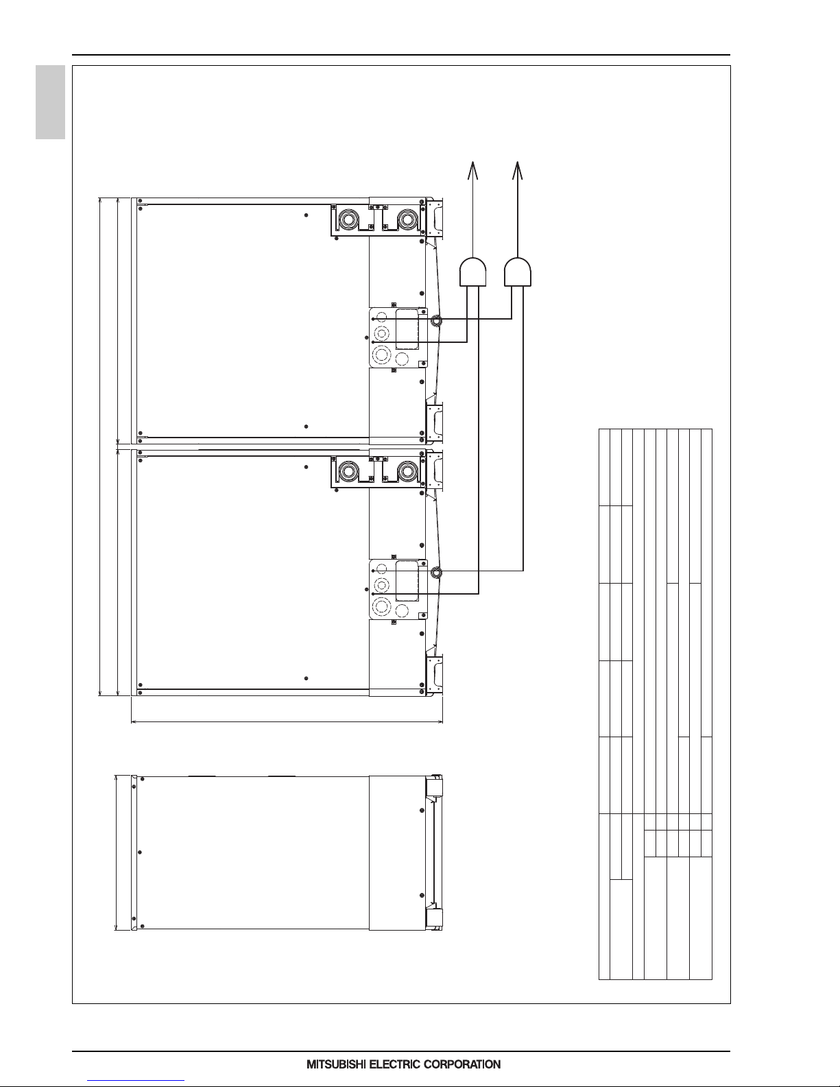
24
WY
MEE15K036
2. EXTERNAL DIMENSIONS
HEAT SOURCE
PQHY-P400,450,500,550,600YSLM-A
Unit: mm
b
e
a
c
d
To indoor unit
Heat Source unit 1 Heat Source unit 2
To indoor unit
Gas Twinning pipe <optional parts>
f
Liquid Twinning pipe <optional parts>
Note 1.Connect the pipes as shown in the figure above. Refer to the table below for the pipe size.
2.Twinning pipe should not be tilted more than 15 degrees from the horizontal plane.
3.See the Installation Manual for the details of Twinning pipe installation.
4.The pipe section before the Twinning pipe (sections "a" and "b" in the figure) must have at least 500mm of straight section
(*including the straight pipe that is supplied with the Twinning pipe).
5.Only use the Twinning pipe by Mitsubishi (optional parts).
Twinning pipe connection size
Package unit name
Component unit name
Heat Source unit 1
Twinning pipe Kit(optional parts)
Heat Source unit 2
PQHY-P400YSLM-A
CMY-Y100VBK3
Indoor unit~Twinning pipe
Lquid
Gas
a
ø28.58b
ø15.88
Twinning pipe~Heat Source unit 1
Lquid
Gas
c
d
Twinning pipe~Heat Source unit 2
Lquid
Gas
e
f
ø19.05
ø19.05
ø9.52
ø9.52
ø22.2
ø22.2
ø12.7
ø12.7
20880 880
1100
550
1780
PQHY-P200YLM-A
PQHY-P200YLM-A
PQHY-P450YSLM-A
PQHY-P250YLM-A
PQHY-P200YLM-A
PQHY-P500YSLM-A
PQHY-P250YLM-A
PQHY-P250YLM-A
PQHY-P550YSLM-A
PQHY-P300YLM-A
PQHY-P250YLM-A
PQHY-P600YSLM-A
PQHY-P300YLM-A
PQHY-P300YLM-A
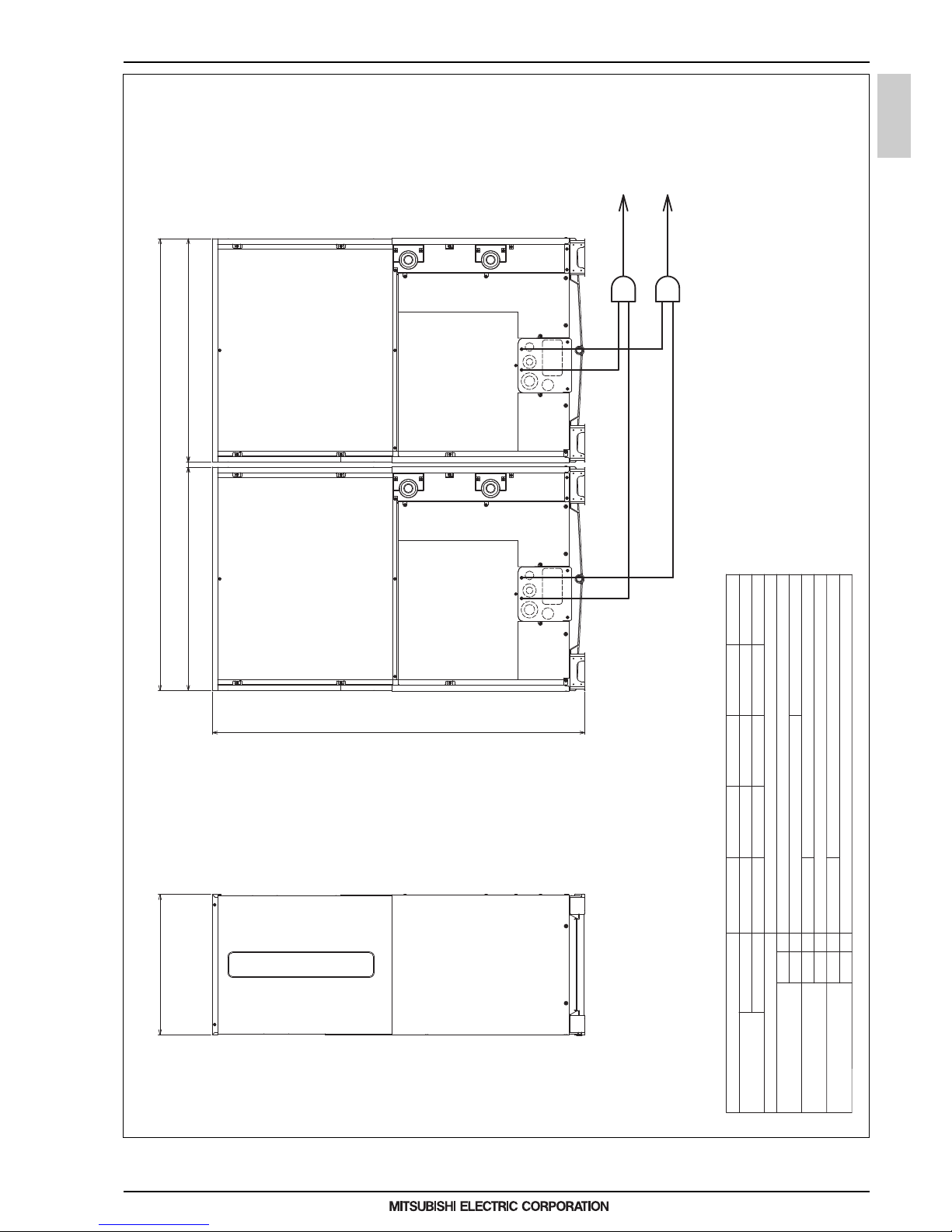
25
WY
MEE15K036
2. EXTERNAL DIMENSIONS
HEAT SOURCE
PQHY-P700, 750, 800, 850, 900YSLM-A
Unit: mm
CMY-Y200VBK2
PQHY-P350YLM-A PQHY-P350YLM-A
b
a
Gas
Liquid
Heat Source unit 2
Heat Source unit 1
Indoor unit~Twinning pipe
Twinning Kit(optional parts)
Component unit name
Package unit name
PQHY-P700YSLM-A PQHY-P750YSLM-A
PQHY-P350YLM-A PQHY-P400YLM-A
PQHY-P400YLM-A PQHY-P400YLM-A PQHY-P450YLM-A
PQHY-P400YLM-A PQHY-P450YLM-A PQHY-P450YLM-A
PQHY-P800YSLM-A PQHY-P850YSLM-A PQHY-P900YSLM-A
d
c
Gas
Liquid
Twinning pipe~Heat Source unit 1
f
e
Gas
Liquid
Twinning pipe~Heat Source unit 2
ø19.05
ø12.7
ø28.58
ø15.88
ø28.58
ø12.7
ø34.93 ø41.28
ø15.88
c
d
b
a
f
e
To indoor unit
Liquid Twinning pipe<optional parts>
Gas Twinning pipe<optional parts>
To indoor unit
Heat Source unit 2Heat Source unit 1
88020880
550
1450
1780
Note 1.Connect the pipes as shown in the figure above. Refer to the table above for the pipe size.
2.Twinning pipes should not be tilted more than 15 degrees from the horizontal plane.
3.See the Installation Manual for the details of Twinning pipe installation.
4.The pipe section before the Twinning pipe (sections "a" and "b" in the figure) must have at least 500mm
of straight section (*including the straight pipe that is supplied with the Twinning pipe).
5.Only use the Twinning pipe by Mitsubishi (optional parts).
Twinning pipe connection size
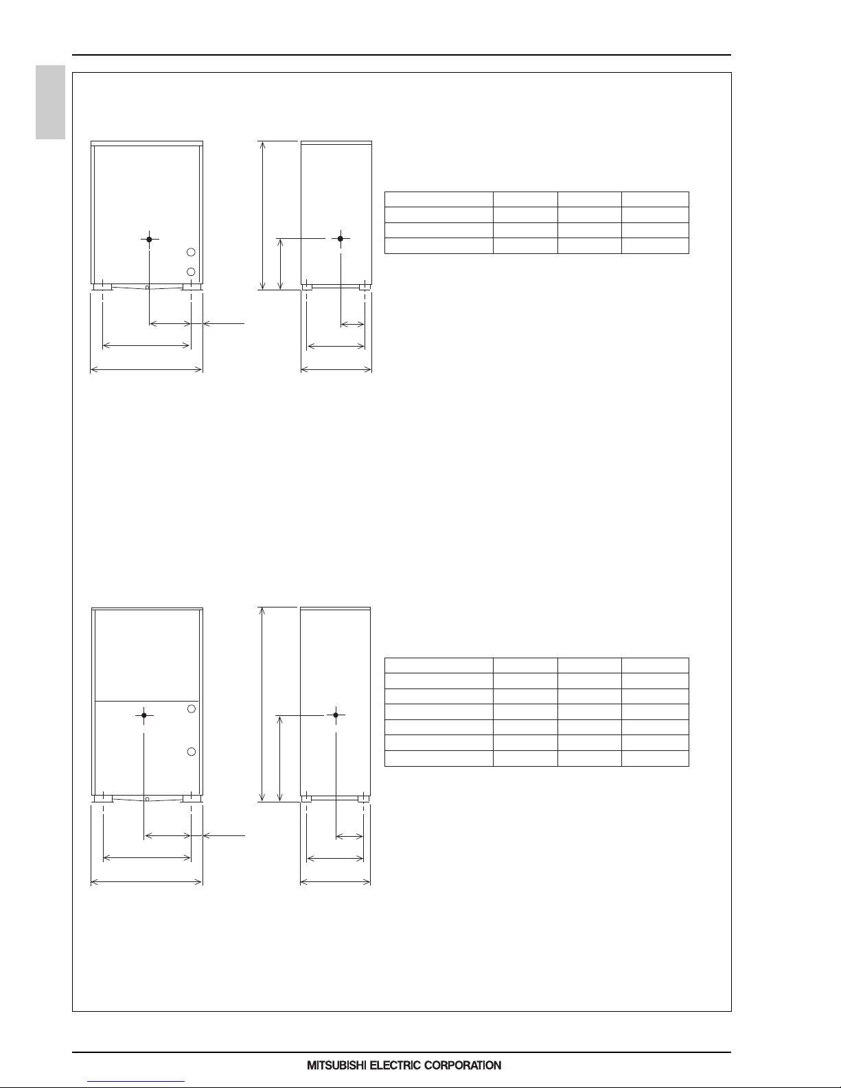
26
WY
MEE15K036
3. CENTER OF GRAVITY
HEAT SOURCE
3. CENTER OF GRAVITY
Model X Y Z
353[13-15/16]
353[13-15/16]
353[13-15/16]
233[9-3/16]
233[9-3/16]
233[9-3/16]
448[17-11/16]
448[17-11/16]
448[17-11/16]
PQHY-P200YLM-A
PQHY-P250YLM-A
PQHY-P300YLM-A
Model X Y Z
382[15-1/16]
382[15-1/16]
382[15-1/16]
382[15-1/16]
365[14-3/8]
365[14-3/8]
233[9-3/16]
233[9-3/16]
233[9-3/16]
233[9-3/16]
224[8-7/8]
224[8-7/8]
632[24-15/16]
632[24-15/16]
632[24-15/16]
632[24-15/16]
650[25-5/8]
650[25-5/8]
PQHY-P350YLM-A
PQHY-P400YLM-A
PQHY-P450YLM-A
PQHY-P500YLM-A
PQHY-P550YLM-A
PQHY-P600YLM-A
PQHY-P200/250/300YLM-A
Unit: mm [in.]
Unit: mm [in.]
PQHY-P350/400/450/500/550/600YLM-A
X
79.5 [3-3/16]
880 [34-11/16]
721 [28-7/16] (*1)
550 [21-11/16]
473 [18-5/8] (*1)
1450 [57-1/8]
Z
Y
*1 Mounting Pitch
*1 Mounting Pitch
880 [34-11/16]
721 [28-7/16] (*1)
X
79.5 [3-3/16]
550 [21-11/16]
473 [18-5/8] (*1)
Y
Z
1100 [43-5/16]
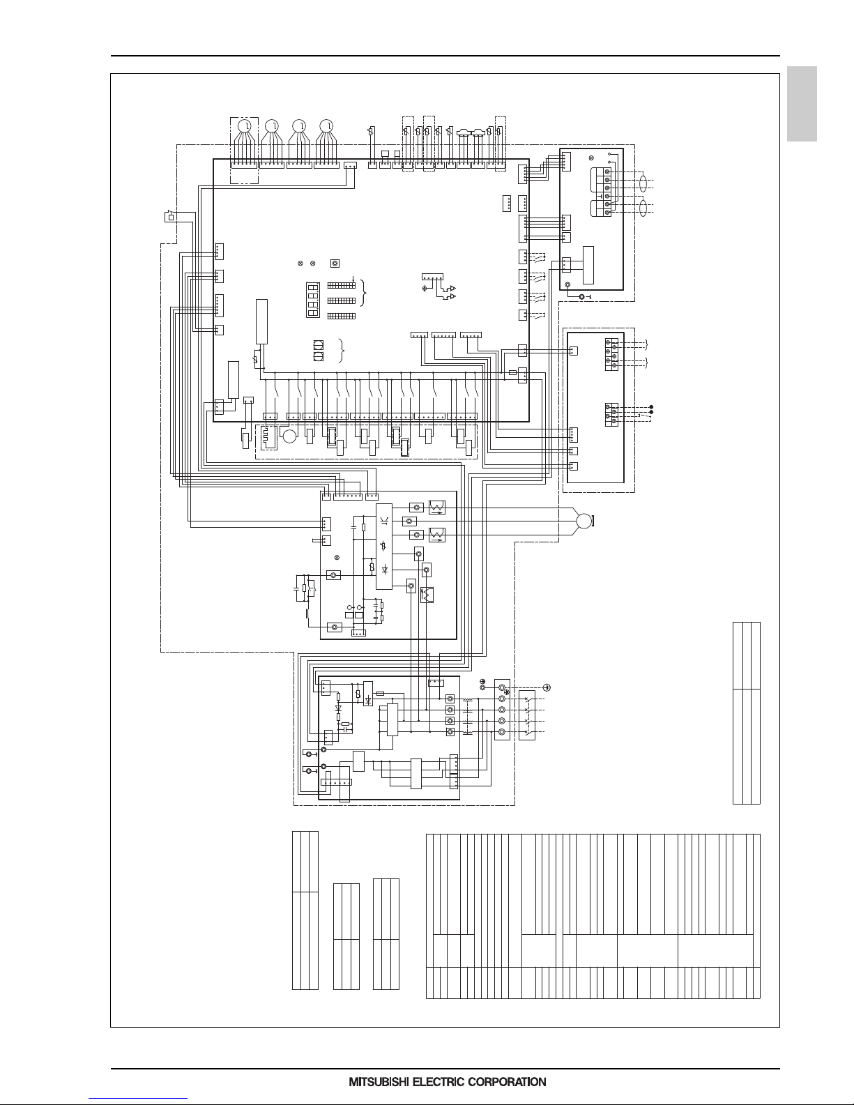
27
WY
MEE15K036
4. ELECTRICAL WIRING DIAGRAMS
HEAT SOURCE
4. ELECTRICAL WIRING DIAGRAMS
PQHY-P200, 250, 300, 350, 400, 450, 500, 550, 600YLM-A
↑↓
12
red
CNPS
1
3
2
1
TP1 TP2
TB3
2
3
TB7
M1M2 M1 M2 S
512 34
1
2
t°
LEVINV
M
1234612
132
346
3
1
CN4
black
31
t°
3
CN2
1
12
1
3
3
1
432
2
3
1
1
TH2
TH4
t°4t°
1
1
CN211
green
23
123
321
5
21
3
2
23
123
CN6
1
t°
2
yellow
CNPOW
t°
1
654
X14
X08
X07
Unit address
setting
CT12
+
351
6
12
34
3
green
CN62
CN990
green
CNTYP4
CN201
Z25
1
TH5
2
SWU2
LED1
SW6
10
Control Board
TH3
CN40
63HS1
CN41
TH7
15
1
SW4
LED3
LEV7
3
3
SET UP(SW6-10)
SC-V
CT22
SC-U
V
M
t°
CN506
red
CNTYP2
black
6
yellow
CN3K
*3
Compressor ON/OFF output
Error detection output
DC12V
CN51
SV7b
U
blue
CN3N
1
3
SV7a
4
TB7 Power
selecting
connector
1
2
5
DCL
black
72C
white
red
6
ON
OFF
M-NET power
supply circuit
1
2
M-NET Board
Power failure
detection circuit
Indoor/Heat source
transmission
cable
INV Board
red
ON
1's
digit
THHS
CN102
C31,C33,
C35,C37
4
1
W
10's
digit
OFF
LED2:Normal operation(Lit)
/ Error(Blink)
CNS2
yellow
CNDC
red
red
MS
3~
2
C100
*5
TH6
U
LED1:Power supply to
Indoor/Heat source
transmission line
ZNR400
+
black
Central control
transmission
cable
*6
SC-L1
ONOFF
FT-N
R30,R32,
R34
Motor
(Compressor)
1
CN04
red
CN43
1
SC-P2
P
CN61
green
CN202
red
C30,C32,
C34,C36
N
CN1
X13
LED1:Normal operation(Lit)
/ Error(Blink)
*4
SC-W
SC-L3
2
CNRYB
P
63H1
4
SW5
10
CN3D
1
CPU power
supply circuit
black
CNAC2
1
*3
ONOFF
10
SWU1
white
CN212
red
SC-L2
2
CNTYP5
green
CN801
red
5
IPM
4
SC-P1
FT-P
blackred
CT3
C1
CNTYP
black
black
SWP01
RSH1
63LS
ZNR1
U
Z24
CN509
yellow
336
CN213
green
SV4b
Function
setting
LED1
Display
setting/
Function
setting
72C
6
7
red
1
2
5
1
CNLVD
CNLVE
yellow
1
F01
AC250V
3.15A T
white
black
1
CNIT
red
R31,R33,
R35
*1.Single-dotted lines indicate wiring not supplied with the unit.
*2.Dot-dash lines indicate the control box boundaries.
*3.Refer to the Data book for connecting input/output
signal connectors.
*4.Daisy-chain terminals (TB3) on the heat source units in the
same refrigerant system together.
*5.Faston terminals have a locking function.
Make sure the terminals are securely locked in place
after insertion. Press the tab on the terminals to
removed them.
*6.Control box houses high-voltage parts.
Before inspecting the inside of the control box,turn off
the power,keep the unit off for at least 10 minutes, and
confirm that the voltage between FT-P and FT-N on
INV Board has dropped to DC20V or less.
*7.Refer to the Data book for wiring terminal block for
Pump Interlock,Operation ON signal,DC0-10V signal output and Power input(24V).
*8.Difference of appliance.
4
1
R1,R5
X05
X06
351
6
CN505
13
CNAC
12
5
123
4
4
4
CN2
21S4b
21S4a
I/O Board
CNAC4
black
21
CNOUT2
21
yellow
451
CNPW
21
blue
TB8
Operation
ON signal
Pump Interlock
*7
2
31
CNAO
green
*7
4
t°
CN992A
yellow
TH8
1
2
t°
1
2
THINV
CNTYP1
black
LEV6
M
12346123456
LEV1
M
CNLVA
CNLVB
red
blue
13
CN5V
yellow
yellow
CN63PW
blue
CNOUT
yellow
CNAO
green
MF1 Fan motor(Radiator panel)
SV1a
SV4a,b,d
TH8
HIC bypass,Controls refrigerant
flow in HIC circuit
Heat exchanger capacity control
For opening/closing the bypass
circuit under the O/S
Water outlet temperature
THINV Outlet temp.detect of heat
exchanger for inverter
TH3
TH2
Subcool bypass outlet temperature
Pipe temperature
TH6 Subcooled liquid refrigerant
temperature
<Symbol explanation>
63HS1
21S4a
4-way valve
Explanation
Symbol
63H1
63LS
Pressure
sensor
Pressure
switch
High pressure protection for the
heat source unit
High pressure
Low pressure
72C
Capacitor(inverter main circuit)C30~C37
Solenoid
valve
Linear
expansion
valve
LEV1
DCL DC reactor
TB1
TB3
TB7
Terminal
block
Central control transmission
cable
Indoor/Heat source transmission
cable
Power supply
TB8
TH4
TH5
TH7
THHS
Function setting connector
IPM temperature
Water inlet temperature
ACC inlet pipe temperature
Discharge pipe temperature
Operation ON signal,
Pump Interlock
Thermistor
Z24,25
Current sensor(AC)
CT12,22,3
L
Choke coil(for high frequency noise
reduction)
LEV6
LEV7
Resistor
For inrush current prevention
For current detection
R1,5
RSH1
SV7a,b,c
Heat exchanger capacity control
Heat exchanger capacity control
Heat exchanger capacity control
Magnetic relay(inverter main circuit)
X12
CN508
blue
3
6
SV4d
1
X02
CN502
black
1
3
M
1~
MF1
SV4a
X04
CN504
yellow
1
SV1a
3
Cooling/Heating switching
21S4b
Heat exchanger capacity control
LEVINV
Heat exchanger for inverter
CN507
black
TB9
*7
*7
DC0-10V
signal output
6:signal
5:GND
(IN)(OUT)
Power input
AC24V or DC24V
(non-polar)
TB9 Power input and signal output
for variable water flow valve
64
531
2
Model name
P200/250/300
P350/400/450/500/550/600
Appliance
*8 do not exist
*8 exist
*9.Difference of appliance.
Model name
PQHY
PQRY
Appliance
*9 do not exist
*9 exist
*10.Difference of appliance.
Model name
PQHY
PQRY
Appliance
*10 exist
*10 do not exist
SV9 For opening/closing the bypass
circuit
X09
351
6
SV9
SV7c
*9
*8
*10
*10
*10
*10
X10
5
*8
CN3
green
1
3
L3 N
365
3
1
L1
L2
341
1
3
1
U
Power Source
3N~
50/60Hz
380/400/415V
Noise filter
1
Surge
absorber
CN5
red
D1
R4
-
Z5
white
F4
AC250V
6.3A T
R5
CN4
blue
red
black
TB21
CN1A
CN2
+
TB1
CN1B
L3 N
TB23 TB24
L2L1
+
DB1
TB22
R6
C11
L
Noise
Filter
Noise filter
L1 L2 L3
N
*11.Difference of appliance.
Model name
P200/250/300/350/400/450/500
P550/600
Appliance
*11 do not exist
*11 exist
CH11
Crankcase heater(for heating the compressor)
*11
X01
CN501
blue
1
3
CH11
4
2
1
1
6
415
 Loading...