

Mitsubishi PMFY-P06NBMU-E1, PMFY-P08NBMU-E, PMFY-P06NBMU-ER5, PMFY-P06NBMU-E#2, PMFY-P06NBMU-ER3 Technical & Service Manual
...
SPLIT-TYPE, HEAT PUMP AIR CONDITIONERS
TECHNICAL & SERVICE MANUAL
Indoor unit
[Model names] [Service Ref.]
PMFY-P06NBMU-E
PMFY-P08NBMU-E
PMFY-P06NBMU-E PMFY-P06NBMU-E
PMFY-P06NBMU-E#2 PMFY-P06NBMU-ER3
PMFY-P06NBMU-ER4 PMFY-P06NBMU-ER5
PMFY-P08NBMU-E PMFY-P08NBMU-E
April 2012
No. OC341
REVISED EDITION-F
R410A / R22
1
1
Revision:
• PMFY-P06/08/12/15NBMUER5 have been added in
REVISED EDITION-F.
• Some descriptions have
been modified.
PMFY-P12NBMU-E
PMFY-P15NBMU-E
PMFY-P08NBMU-E#2 PMFY-P08NBMU-ER3
PMFY-P08NBMU-ER4 PMFY-P08NBMU-ER5
PMFY-P12NBMU-E PMFY-P12NBMU-E
1
PMFY-P12NBMU-E#2 PMFY-P12NBMU-ER3
PMFY-P12NBMU-ER4 PMFY-P12NBMU-ER5
PMFY-P15NBMU-E PMFY-P15NBMU-E
1
PMFY-P15NBMU-E#2 PMFY-P15NBMU-ER3
PMFY-P15NBMU-ER4 PMFY-P15NBMU-ER5
CONTENTS
1. TECHNICAL CHANGES
2. FEATURES
3. PART NAMES AND FUNCTIONS
4. SPECIFICATION
5. OUTLINES AND DIMENSIONS
6. WIRING DIAGRAM
7.
REFRIGERANT SYSTEM DIAGRAM
8. MICROPROCESSOR CONTROL
9. TROUBLESHOOTING
10. DISASSEMBLY PROCEDURE
11. RoHS PARTS LIST
...........................................
• Please void OC341
REVISED EDITION-E.
NOTE:
• This manual describes
only service data of the
indoor units.
• RoHS compliant products
have <G> mark on the
spec name plate.
• For servicing RoHS compliant products, refer to the
RoHS PARTS LIST.
.......................
........
...................................
............
.............................
........................
...........
.............................
....
.......
10
14
15
22
31
35
2
3
3
5
9
INDOOR UNIT

Use the specifi ed refrigerant only
OC341F
Never use any refrigerant other than that specifi ed.
Doing so may cause a burst, an explosion, or fi re when the unit is being used, serviced, or disposed of.
Correct refrigerant is specifi ed in the manuals and on the spec labels provided with our products.
We will not be held responsible for mechanical failure, system malfunction, unit breakdown or accidents caused
by failure to follow the instructions.
1
PMFY-P06NBMU-ER4 → PMFY-P06NBMU-ER5
PMFY-P08NBMU-ER4 → PMFY-P08NBMU-ER5
PMFY-P12NBMU-ER4 → PMFY-P12NBMU-ER5
PMFY-P15NBMU-ER4 → PMFY-P15NBMU-ER5
• INDOOR CONTROLLER BOARD (I.B) has been changed. (S/W version up)
PMFY-P06NBMU-ER3 → PMFY-P06NBMU-ER4
PMFY-P08NBMU-ER3 → PMFY-P08NBMU-ER4
PMFY-P12NBMU-ER3 → PMFY-P12NBMU-ER4
PMFY-P15NBMU-ER3 → PMFY-P15NBMU-ER4
1. DRAIN PIPE has been changed.
2. JOINT SOCKET (FOR DRAIN PIPE) has been added.
PMFY-P06NBMU-E#2 → PMFY-P06NBMU-ER3
PMFY-P08NBMU-E#2 → PMFY-P08NBMU-ER3
PMFY-P12NBMU-E#2 → PMFY-P12NBMU-ER3
PMFY-P15NBMU-E#2 → PMFY-P15NBMU-ER3
• CONTROLLER BOARD (I.B) has been changed. (It is possible to extract a signal for an external heater.)
TECHNICAL CHANGES
PMFY-P06NBMU-E1 → PMFY-P06NBMU-E#2
PMFY-P08NBMU-E1 → PMFY-P08NBMU-E#2
PMFY-P12NBMU-E1 → PMFY-P12NBMU-E#2
PMFY-P15NBMU-E1 → PMFY-P15NBMU-E#2
1. CONTROLLER BOARD (I.B) has been changed.
2. PANEL has been changed.
PMP-16BMU → PMP-16BMUW
(White : 0.98Y 8.99/0.63) (Pure white : 6.4Y 8.9/0.4)
3. FAN MOTOR (MF) has been changed.
4. THERMISTORs (TH22, TH23) have been changed.
PMFY-P06NBMU-E → PMFY-P06NBMU-E1
PMFY-P08NBMU-E → PMFY-P08NBMU-E1
PMFY-P12NBMU-E → PMFY-P12NBMU-E1
PMFY-P15NBMU-E → PMFY-P15NBMU-E1
1. FAN MOTOR (MF) has been changed.
2. CONTROLLER BOARD (I.B) has been changed.
2
2
OC341F
Models Cooling capacity / Heating capacity
PMFY-P06NBMU-E 6,000 / 6,700 Btu/h
PMFY-P08NBMU-E 8,000 / 9,000 Btu/h
PMFY-P12NBMU-E 12,000 / 13,500 Btu/h
PMFY-P15NBMU-E 15,000 / 17,000 Btu/h
FEATURES
Indoor Unit
1. Fresh Air Intake
Air recycled indefinitely can become stale and stagnant with air quality suffering significantly. Fresh air is the
answer and it is for this reason that the PMFY- series takes in air directly from outdoors. This fresh air intake
allows you to enjoy the comfort of crisp, refreshing air in the confines of your living or working space.
2. Light and Compact
The main unit weighs only 31 lb. and the panel merely 7 lb. This makes the PMFY- series one of the light-
est in the industry. The unit size is also quite small, having been standardized to a strikingly compact 33-5/8
inch. All of this make the chore of installation and maintenance that much simpler and easier.
3
PART NAMES AND FUNCTIONS
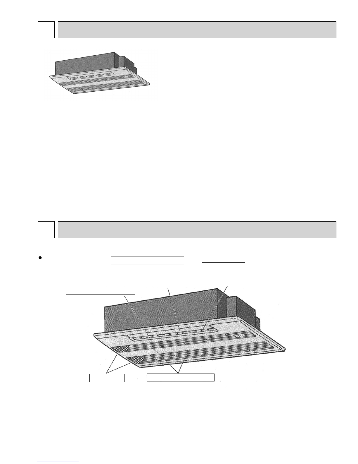
Indoor Unit
Horizontal Air Outlet
Filters
Remove dust and pollutants
from return air.
Auto Air Swing Vane
Disperses airflow up and
down and adjusts the angle
of airflow direction.
Air intake
Returns air from room.
Guide vane
Air flow can be changed to horizontal
by moving the guide vane to the left or right.
3

PAR-21MAA
ON/OFF
FILTER
CHECK
OPERATION
CLEAR
TEST
TEMP.
MENU
BACK DAY
MONITOR/SET
CLOCK
ON/OFF
Temperature setting buttons
Down
Up
Timer Menu button
(Monitor/Set button)
Mode button (Return button)
Set Time buttons
Back
Ahead
Timer On/Off button
(Set Day button)
Opening the
cover
ON/OFF button
Fan Speed button
Filter button
(<Enter> button)
Test Run button
Check button (Clear button)
Airflow Up/Down button
Louver button
( Operation button)
T o return operation
number
Ventilation button
( Operation button)
To go to next operation
number
Built-in temperature sensor
Wired remote controller
OC341F
Once the controllers are set, the same operation mode can be repeated by simply pressing the ON/OFF button.
Note:
The phrase "Wired remote controller" in this manual refers only to the PAR-21MAA.
If you need any information for the other remote controller, please refer to either the installation manual or initial setting manual which are included in
remote controller's box.
Display Section
For the purposes of this explanation,
all parts of the display are shown.
During actual operation, only
the relevant items will be lit.
Identifies the current operation
Shows the operating mode, etc.
*Multilanguage display is available.
“Centrally Controlled” indicator
Indicates that operation from the
remote controller has been prohibited by a master controller.
“Timer is Off” indicator
Indicates that the timer is off.
Temperature Setting
Shows the target temperature.
Day-of-Week
Shows the current day of the week.
Time/Timer Display
Shows the current time, unless the simple or Auto Off
timer is set.
If the simple or Auto Off timer is set, the time to be
switched off is shown.
Up/Down Air Direction indicator
Shows the direction of the
outcoming airflow.
“One Hour Only” indicator
Displays if the airflow is set to
low or downward during COOL
or DRY mode. (Operation varies
according to model.)
The indicator goes off in one hour,
when the airflow direction also
changes.
°F°C
TIME SUN MON TUE WED THU FRI SAT
TIMER
AFTER
ONLY1Hr.
ERROR CODE
°F°C
Hr
AFTER
Room Temperature display
Shows the room temperature. The room
temperature display range is 46~102°F.
The display blinks if the temperature
is less than
Louver display
Indicates the action of the swing louver.
Does not appear if the louver is not
running.
(Power On indicator)
Indicates that the power is on.
4
ON
OFF
FUNCTION
FILTER
WEEKLY
SIMPLE
AUTO OFF
46°F or 102°F
or more.
“Sensor” indication
Displays when the remote controller
sensor is used.
“Locked” indicator
Indicates that remote controller buttons have been locked.
“Clean The Filter” indicator
To be displayed on when it is time to
clean the filter.
Timer indicators
The indicator comes on if the corresponding timer is set.
Fan Speed indicator
Shows the selected fan speed.
Ventilation indicator
Appears when the unit is running in
Ventilation mode.
4
OC341F
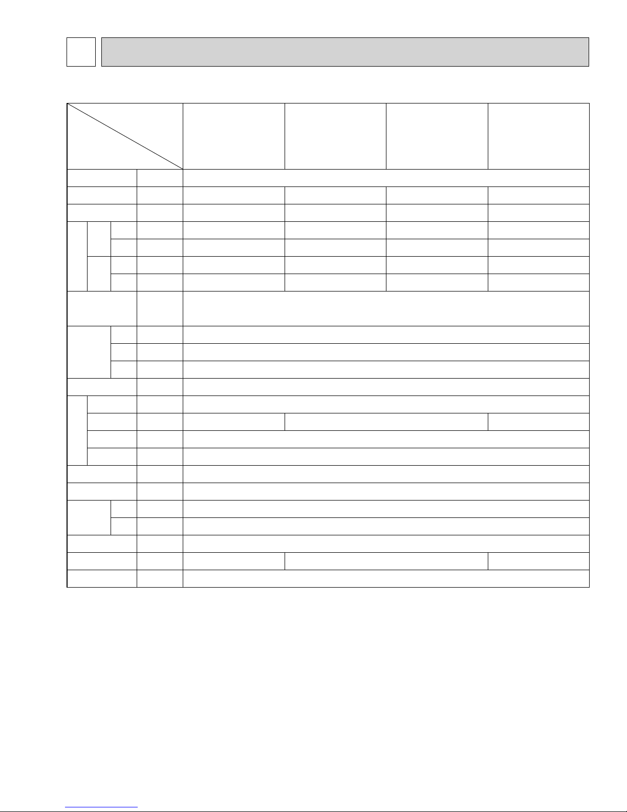
SPECIFICATION
4-1. SPECIFICATIONS
Service ref.
PMFY-P06NBMU-E
PMFY-P06NBMU-E#2
PMFY-P06NBMU-E
Item
PMFY-P06NBMU-ER3
PMFY-P06NBMU-ER4
PMFY-P06NBMU-ER5
Power V · H
Cooling
capacity Btu/h 6,000 8,000 12,000 15,000
Z
PMFY-P08NBMU-E
PMFY-P08NBMU-E
1
PMFY-P08NBMU-E#2
PMFY-P08NBMU-ER3
PMFY-P08NBMU-ER4
PMFY-P08NBMU-ER5
Single phase 208-230V 60Hz
PMFY-P12NBMU-E
PMFY-P12NBMU-E
1
PMFY-P12NBMU-E#2
PMFY-P12NBMU-ER3
PMFY-P12NBMU-ER4
PMFY-P12NBMU-ER5
1
PMFY-P15NBMU-E
PMFY-P15NBMU-E
1
PMFY-P15NBMU-E#2
PMFY-P15NBMU-ER3
PMFY-P15NBMU-ER4
PMFY-P15NBMU-ER5
Heating capacity
Cooling
Btu/h 6,700 9,000 13,500 17,000
kW 0.042 0.042 0.044 0.054
Input
Heating
Cooling
kW 0.042 0.042 0.044 0.054
A 0.20 0.20 0.21 0.26
Current
Electric characteristic
Heating
Exterior
(munsell symbol)
Height
Dimensions
Width
Depth
A 0.20 0.20 0.21 0.26
—
Munsell <0.98Y 8.99/0.63> (PMFY-P·NBMU-E
Unit : Galvanized sheets · Standard grilles : ABS resin acrylic coating
(1)
) / <6.4Y 8.9/0.4> (PMFY-P·NBMU-E#2/ER3/ER4/ER5)
in. 9-1/16<1-3/16>
in. 31-15/16<39-3/8>
in. 15-9/16<18-1/2>
Heat exchanger — Cross fi n
Fan × No — Line fl ow fan × 1
Air fl ow W3 CFM 230-250-280-300 250-280-300-320 270-300-340-370
External
static pressure
Fan
Fan motor
output
in W.G. 0
kW 0.028
Insulator — Polyethylene sheet
Air fi lter — PP honey comb fabric
Pipe
dimensions
Gas
side
Liquid
side
Field drain pipe size
[in. 1/2
[in. 1/4
[
in. 1 O.D. (PVC pipe VP-20 connectable)
Noise level W3 dB 27-30-33-35 32-34-36-37 33-35-37-39
Product weight Ib. 31<7>
Note 1. Rating conditions
Cooling: Indoor: D.B. 80°F W.B. 67°F
outdoor: D.B. 95°F W.B. 75°F
Heating: Indoor: D.B. 70°F
outdoor: D.B. 47°F W.B. 43°F
Note 2. The number indicated in < > is for the grille.
W 3. Air flow and the noise level are indicated as Low - Medium2 - Medium1 - High.
5

4-2. ELECTRICAL PARTS SPECIFICATIONS
OC341F
Service Ref.
Parts name
Room temperature
thermistor
Liquid pipe thermistor
Gas pipe thermistor
Fuse
(Indoor controller board)
Fan motor
Vane motor
Symbol
TH21
TH22
TH23
FUSE
MF
MV
PMFY-P06NBMU-E
PMFY-P06NBMU-E
PMFY-P06NBMU-E#2
PMFY-P06NBMU-ER3
PMFY-P06NBMU-ER4
PMFY-P06NBMU-ER5
Resistance 30°F/15.8k, 50°F/9.6k, 70°F/6.0k, 80°F/4.8k, 90°F/3.9k, 100°F/3.2k
Resistance 30°F/15.8k, 50°F/9.6k, 70°F/6.0k, 80°F/4.8k, 90°F/3.9k, 100°F/3.2k
Resistance 30°F/15.8k, 50°F/9.6k, 70°F/6.0k, 80°F/4.8k, 90°F/3.9k, 100°F/3.2k
PMFY-P08NBMU-E
1
PMFY-P08NBMU-E
PMFY-P08NBMU-E#2
PMFY-P08NBMU-ER3
PMFY-P08NBMU-ER4
PMFY-P08NBMU-ER5
250V 6A (PMFY-P·NBMU-E
250V 6.3A (PMFY-P·NBMU-E#2/ER3/ER4/ER5)
DC Brushless Motor
8-pole OUTPUT 28W
PMFY-P12NBMU-E
1
PMFY-P12NBMU-E
PMFY-P12NBMU-E#2
PMFY-P12NBMU-ER3
PMFY-P12NBMU-ER4
PMFY-P12NBMU-ER5
PN0H28-MB
MSFJC 20M23
12V/380
(1))
PMFY-P15NBMU-E
PMFY-P15NBMU-E
1
PMFY-P15NBMU-E#2
PMFY-P15NBMU-ER3
PMFY-P15NBMU-ER4
PMFY-P15NBMU-ER5
1
Drain pump
Drain sensor
Linear expansion valve
Power supply
terminal block
Transmission
terminal block
MA-remote controller
terminal block
DP
DS
LEV
TB2
TB5
TB15
PJV-1063
208-240V 50/60Hz
Thermistor resistance 30"F/6.3k, 50"F/3.9k, 70"F/2.5k, 80"F/2.0k, 90"F/1.6k, 100"F/1.3k
DC12V Stepping motor drive
port dimension :
(L1, L2, GR) Rated to 330V 30A
(M1, M2, S) Rated to 250V 20A
(1,2) Rated to 250V 10A
Note : Refer to WIRING DIAGRAM for the supplied voltage.
+
3.2
EDM-40YGME
(0~2000pulse)
+
+
+
6
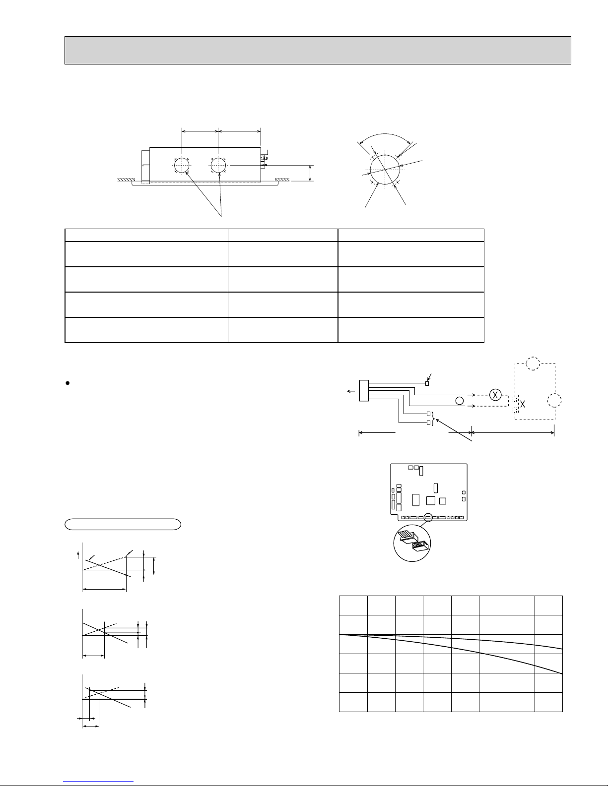
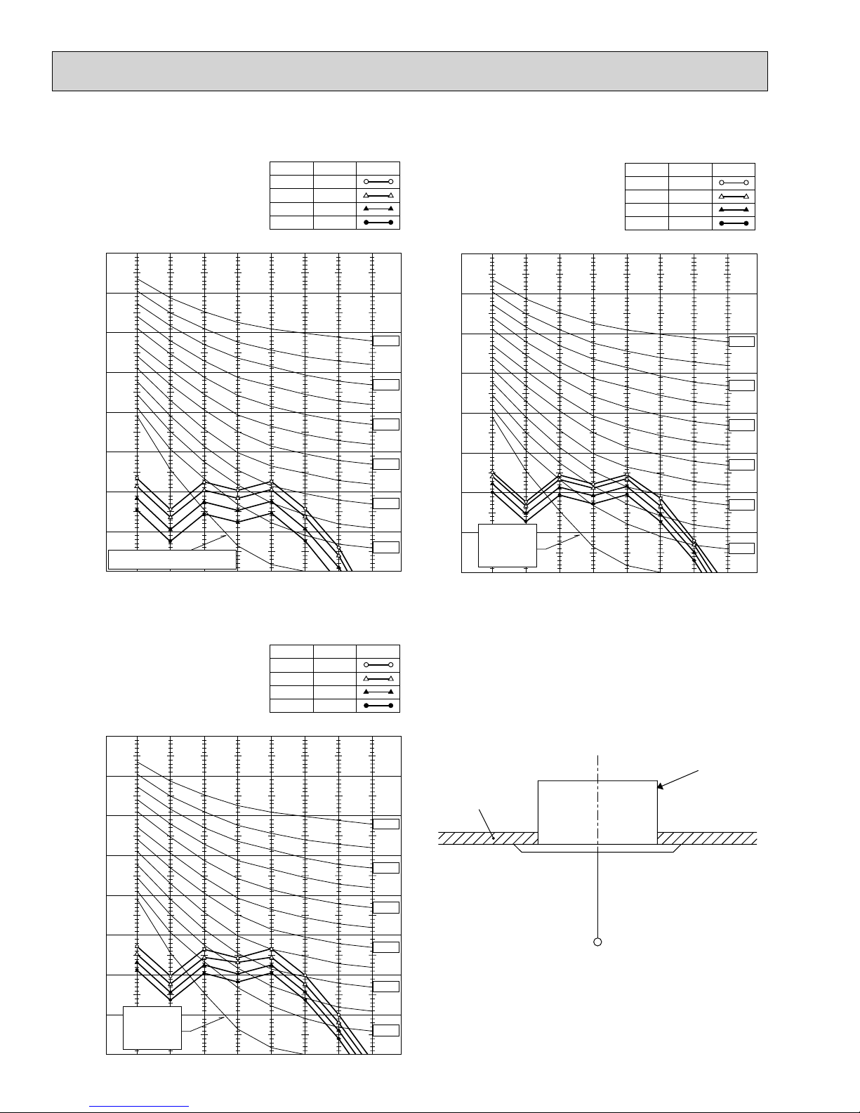
4-3. AIR CAPACITY TAKEN FROM OUTSIDE
OC341F
PMFY-P·NBMU-E series are capable of taking air from outside. When taking air from outside, the duct fan is used.
The air capacity should be 20% or less of the airflow SPEC (Hi).
9-13/16 11-3/8
90
4-Ø1/8
3-15/16
Ø
Fresh air intake hole
(Knockout)
Service Ref. Air fl ow (Hi) Air capacity taken from outside
PMFY-P06NBMU-E/E1/E#2/ER3/ER4/ER5
PMFY-P08NBMU-E/E1/E#2/ER3/ER4/ER5
PMFY-P12NBMU-E/E1/E#2/ER3/ER4/ER5
PMFY-P15NBMU-E/E1/E#2/ER3/ER4/ER5
300 CFM 60CFM
320 CFM 64CFM
320CFM 64CFM
370CFM 74CFM
Operation in conjunction with duct fan (Booster fan)
Whenever the indoor unit is operating, the duct fan
operates.
(1) Connect the optional multiple remote controller
adaptor (PAC-SA88HA-E) to the connector CN51
on the indoor controller board.
(2) Drive the relay after connecting the 12V DC relay
between the Yellow and Orange connector lines.
(w)Use a relay of 1W or smaller.
MB: Electromagnetic switch power relay for duct fan.
X: Auxiliary relay (12V DC LY-1F)
4-1/4
Fresh air intake hole
(Knockout)
CN51
on
indoor unit
board
5
1
Connector (5P)
Indoor unit side
Ø4-
13/16
(Unit: inch)
Be sure to secure insulation
Green
material by tape, etc.
Yellow
Orange
Red
Brown
Multiple remote
controller adapter
PAC-SA88HA-E
Indoor controller board
+
Installation at site
Be sure to secure insulation
material by tape, etc.
Distance between indoor
controller board and relay
must be within 33 feet.
~
MB
How to read curves
Q
Duct characteristics
at site
A
C
B
A
EC
AD
Q…Designed amount of fresh air
intake <CFM>
A…Static pressure loss of fresh air
intake duct system with air flow
amount Q <in. W.G>
B…Forced static pressure at air condi-
tioner inlet with air flow amount Q
C…Static pressure of booster fan with
air flow amount Q <in. W.G>
D…Static pressure loss increase
amount of fresh air intake duct
system for air flow amount Q
E…Static pressure of indoor unit with
air flow amount Q <in. W.G>
Qa…Estimated amount of fresh air
intake without D <CFM>
Curve in the
right graphs
0
Q
Q
Qa
<in. W.G>
<in. W.G>
Multiple remote
controller adapter
PAC-SA88HA-E
CN51
Characteristic diagram of air capacity taken from outside of PMFY-P·NBMU-E
0.2
0.1
0
-0.1
-0.2
Static pressure (in.W.G.)
-0.3
-0.4
010
20
30 40 50 60 70 80
Air flow (CFM)
7
2 intake
1 intake
4-4. NOISE CRITERION CURVES
OC341F
PMFY-P06NBMU-E
PMFY-P06NBMU-E
PMFY-P06NBMU-E#2
PMFY-P06NBMU-ER3
PMFY-P06NBMU-ER4
1
NOTCH
High
Medium1
Medium2
Low
PMFY-P06NBMU-ER5
90
SPL(dB)
35
33
30
27
LINE
PMFY-P08/12NBMU-E
PMFY-P08/12NBMU-E
1
PMFY-P08/12NBMU-E#2
PMFY-P08/12NBMU-ER3
PMFY-P08/12NBMU-ER4
PMFY-P08/12NBMU-ER5
90
NOTCH
High
Medium1
Medium2
Low
SPL(dB)
37
36
34
32
LINE
80
70
60
50
40
30
20
APPROXIMATE THRESHOLD OF HEARING
FOR CONTINUOUS NOISE
OCTAVE BAND SOUND PRESSURE LEVEL, dB (0 dB = 0.0002 μbar)
10
63 125 250 500 1000 2000 4000 8000
BAND CENTER FREQUENCIES, Hz
PMFY-P15NBMU-E
PMFY-P15NBMU-E
1
PMFY-P15NBMU-E#2
PMFY-P15NBMU-ER3
PMFY-P15NBMU-ER4
PMFY-P15NBMU-ER5
90
NOTCH
High
Medium1
Medium2
Low
SPL(dB)
39
37
35
33
NC-70
NC-60
NC-50
NC-40
NC-30
NC-20
LINE
OCTAVE BAND SOUND PRESSURE LEVEL, dB (0 dB = 0.0002 μbar)
80
70
60
50
40
30
APPROXIMATE
20
THRESHOLD OF
HEARING FOR
CONTINUOUS
NOISE
10
63 125 250 500 1000 2000 4000 8000
BAND CENTER FREQUENCIES, Hz
NC-70
NC-60
NC-50
NC-40
NC-30
NC-20
80
70
60
50
40
30
APPROXIMATE
20
THRESHOLD OF
HEARING FOR
CONTINUOUS
OCTAVE BAND SOUND PRESSURE LEVEL, dB (0 dB = 0.0002 μbar)
NOISE
10
63 125 250 500 1000 2000 4000 8000
BAND CENTER FREQUENCIES, Hz
NC-70
NC-60
NC-50
NC-40
NC-30
NC-20
UNIT
CEILING
5ft
MICROPHONE
8
5
OC341F
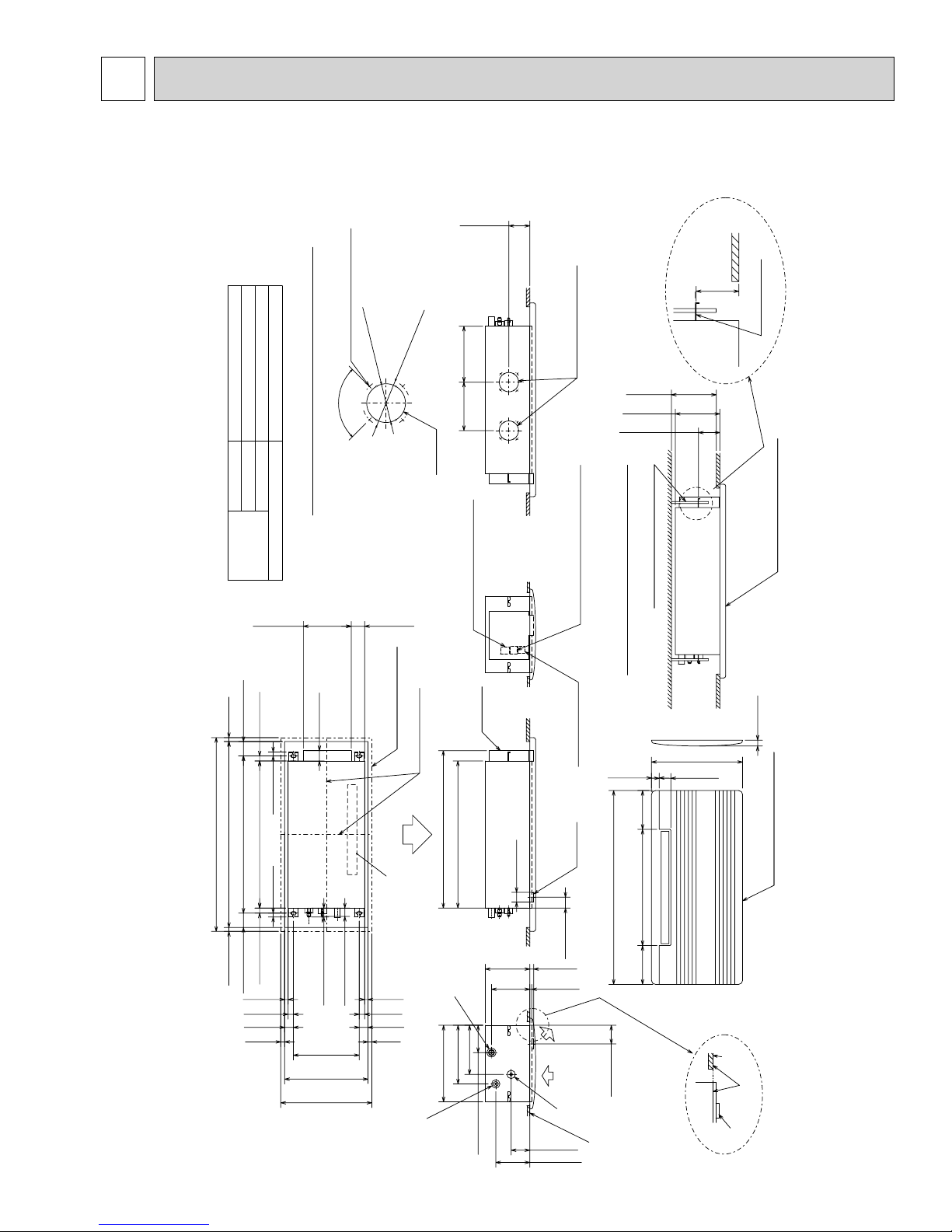
OUTLINES AND DIMENSIONS
PMFY-P06NBMU-E/E1/E#2/ER3/ER4/ER5
PMFY-P08NBMU-E/E
PMFY-P12NBMU-E/E
1/E#2/ER3/ER4/ER5
1/E#2/ER3/ER4/ER5
PMFY-P15NBMU-E/E1/E#2/ER3/ER4/ER5
122)
100)
:
:
1/2F(:12.7)
1/4F(:6.35)
OD:1-11/16(:43)
Gas pipe
Liquid pipe
pipe cover
piping
Refrigerant
4-:1/8(:2.8) Burring hole
90°
PVC pipe:VP-20[OD:31/32(:25)
Details of fresh air intake hole
Drainage piping
4-13/16(
:
3-15/16(
:
Knockout
11-3/8
(288.5)
(250)
9-13/16
4-4/16(108)
Flesh air intake hole
around indoor unit
or more
9-1/2(235)
9-1/16(230)
4-5/16(110)
Unit : inch (mm)
(110)
4-5/16
Mounting plate
Panel(grille):PMP-16BMU(W)
2-15/18(74.5)
1-1/32(26)
13/16(20)13/16(20)
Suspension bolt pitch
Ceiling opening
Outer side of grille
29-7/8(759)
37-13/16(960)
31-15/18(811)
39-3/8(1000)
1-1/32(26)
2-15/18(74.5)
Top
9-3/8(247)
13/16(20)
13/16(20)
11/16(17.5)
1-1/8(28)
1-25/32(45)
13/16(20)
2-1/16(53)
1-13/18(46)
1-11/16(43)
13-3/8(340)
16-15/16(430)
8-1/2(470)
2-11/16(69)
Outer line of grille
Center of unit
Air outlet(lower)
11/16(17.5)
1-1/8(28)
1-25/32(45)
13/16(20)
Suspension bolt pitch
Ceiling opening
Outer side of grille
Refrigirant pipe(gas)
31-15/16(812)
25)]
:
31/32(
:
PVC pipe:
VP-20
Drainage pipe
ޓޓޓ[OD
11-7/8(302)
15-9/16(395)
12.7)
:
1/2(
:
OD
Right side
Terminal block for power supply
Elect box
10(254)
5-9/16(140)
50)
:
1-31/32(
:
(230)
9-1/16
(198)
7-13/16
29-7/8(759)
Suspension bolt(M10 or W3/8)
Terminal block for transmission
Installation space required
remote-controller
Terminal block for
1-9/16(40)
7-7/8
Drain pan
Outer side of grille
23-5/8(600)
39-3/8(1000)
Front
(2-3/16(56))
13/16(20)
(13/32(10))
6.35)
:
1/4(
:
OD
pipe(liquid)
Refrigirant
3-3/8(96)
6-15/16(176)
7-7/8
(3-3/8(96))
Ceiling panel
Left side
(200) (200)
2-3/8(60)
1-3/16(30)
outer side of grille
18-1/2(470)
Panel(grille):PMP-16BMU(W)
Lower view
panel
Ceiling
Same line
Drain pan
9
6
OC341F
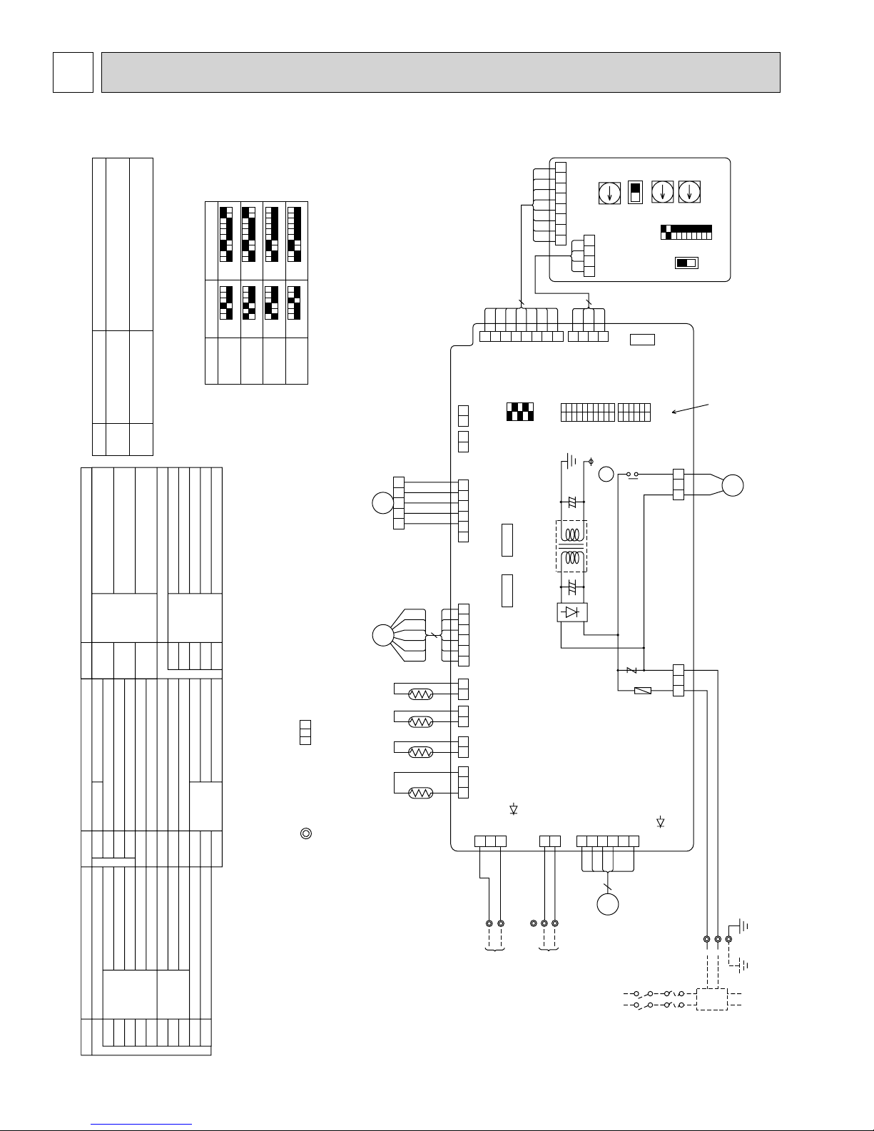
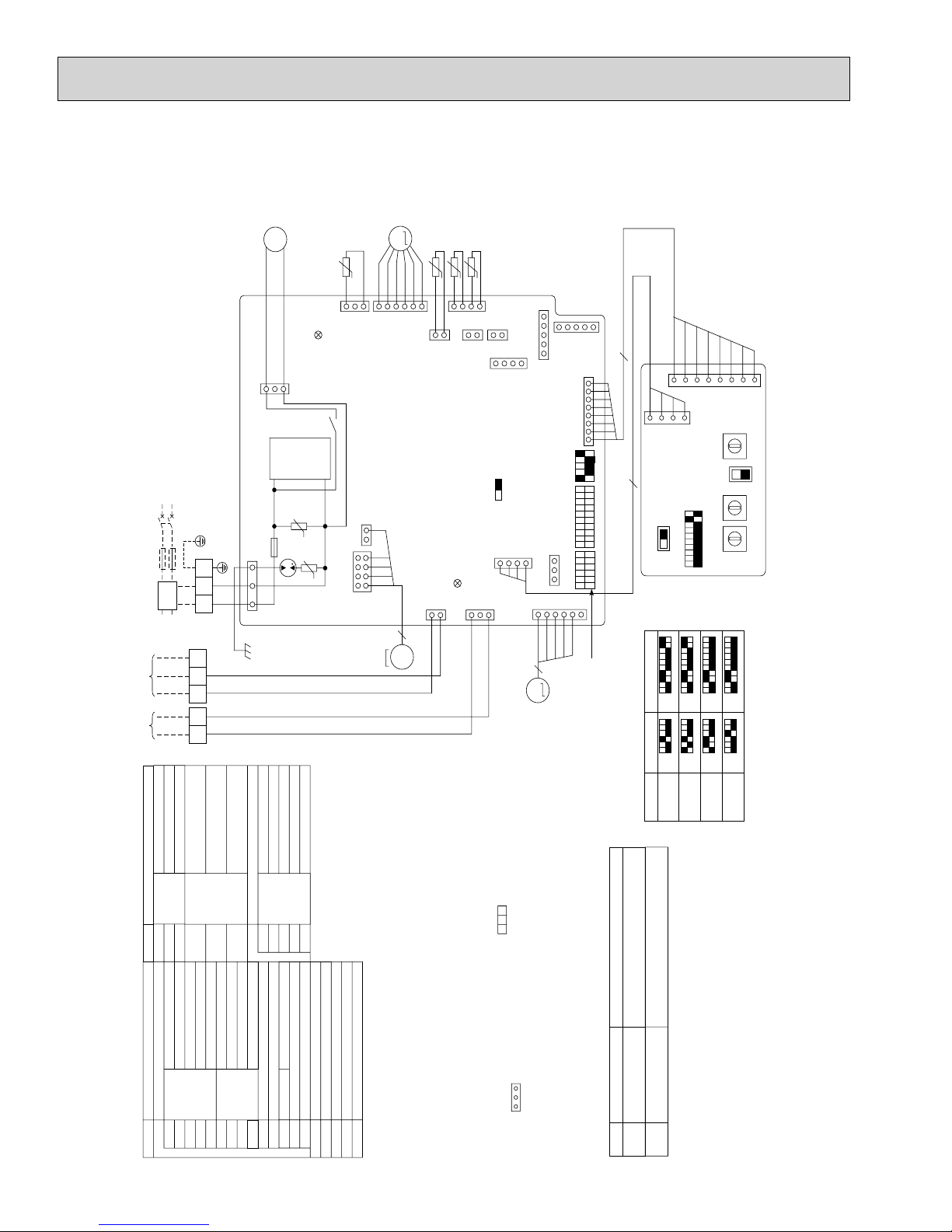
WIRING DIAGRAM
PMFY-P06NBMU-E PMFY-P08NBMU-E PMFY-P12NBMU-E PMFY-P15NBMU-E
SW3
ON
Main power supply (Indoor unit:208-230V)
Power on Lamp is lit.
Power supply for MA-Remote controller
on Lamp is lit.
SW2
ON
Models
<fig. +1>
Power supply for
MA-Remote controller
Main power supply
Mark Meaning Function
LED1
LED on indoor board for service
Thermistor Room temp. detection
Symbol Name
TH21
LED2
/5.4k)
/5.4k)
F
/15k, 77˚
F
(32˚
F
/5.4k)
F
/15k, 77˚
1/15k, 77˚
F
F
Pipe temp. detection / Liquid
(32˚
Pipe temp. detection / Gas
(32˚
Mode selection
Switch
SW1
TH22
A.B Address board
TH23Fan motor (with inner thermo)
Voltage selection
Address setting 1s digit
Address setting 10ths digit
SW5
SW11
SW12
SW14 Branch No.
10
9
8
1234567
OFF
123456
OFF
P06
ON
OFF
ON
OFF
P08
10
9
8
1234567
ON
OFF
123456
ON
OFF
P12
10
10
9
9
8
8
7
7
123456
123456
ON
OFF
123456
123456
ON
OFF
P15
(+2) Use copper supply wire.
MV
LEV
TH21
No.
BRANCH
0
SW14SWC
CN82
(RED)
ADDRESS
8 7 6 5 4 3 2 1
CN43
(RED)
4321
4
4
332
(RED)
ADDRESS
1
CN42
ADDRESS
12345678910
SW3
X1
T
1
A.B
8
87654
2 1
CN27
CN25
GRN
YLW
ORN
RED
BRN
1 2 3 4 5
VANE
(GRN)
CN6V
6 5 4 3 2 1 2 1
WHT
RED
6
YLW
ORN
BRN
BLU
LEV
CN60
(WHT)
6 5 4 3 2 1
2 1
CN20
(RED)
INTAKE
2 1
CN21
(WHT)
LIQUID
OFF
ON
(RED)
15
15
3
CN81
ADDRESS
12345
SW4
CN52
(GRN)
REMOTE
INDICATION
CN51
(WHT)
CONTROL
CENTRALLY
2
1
(WHT)
REMOTE
SW2
X1
FUSE
DIGIT
1s
0
SW11
230V208V
CN32
SWITCH
123456
OFF
ON
6A
250V
CNP
(WHT)
3212 13
CND
(RED)
DIGIT
10ths
0
SW12
12345678910
OFF
ON
SW1
SW5
See fig. +1
DP
Drain pump
Vane motor
X1 Aux.relay
LED1 Power supply (I.B)
LED2 Power supply (I.B)
T Transformer
Symbol Name
Symbol Name
I.B Indoor controller board
[Legend]
Damper
Remote switch
Connector Humidifier
CN25
CN27
CN32
MF
MV
Centrally control
Remote Indication
CN51
CN52
Power supply
Drain sensor
Drain pump
Ter minal
block
DS
DP
TB2
TB5 Transmission
LEV Linear expansion valve
Capacity code
Mode selection
Model selection
Switch
SW2
SW3
SW4
ZNR Varistor
FUSE Fuse (6A / 250V)
TB15 MA-Remote Controller
Note
1. At servicing for outdoor unit, always follow the wiring diagram of outdoor unit.
2. In case of using MA-Remote controller, please connect to TB15. (Remote controller wire is non-polar.)
3. In case of using M-NET, please connect to TB5. (Transmission wire is non-polar.)
DS TH23 TH22
4. Symbol [S] of TB5 is the shield wire connection.
5. Symbols used in wiring diagram above are, : terminal block, :connecter.
6. The setting of the SW2, SW3 dip switches differs in the capacity. For the detail, refer to fig. +1.
7.Please set the switch SW5 according to the power supply voltage.
10
I.B
2 1
GAS
(BLK)
CN29
CN31
(WHT)
DRAIN
3 2 1
(BLU)
CN3A
231
ORN
TB15
1
TO MA-REMOTE
LED2
ORN
TB5
2
SHIELD)
(
S
CONTROLLER
DC8.7-13V
TO OUTDOOR UNIT
(BLU)
CN2M
(M-NET)
2
1
BLU
BLU
M2
M1
BC CONTROLLER
REMOTE CONTROLLER
DC24-30V
)
WHT
FAN
(
1234556
MF
POWER SUPPLY
~ / N 208—230V 60Hz
BREAKER
(15A)
LED1
FUSE(15A)
<+2>
TB2
RED
L1
BLU
GRN / YLW
L2
GR
PULL BOX
TO NEXT INDOOR UNIT
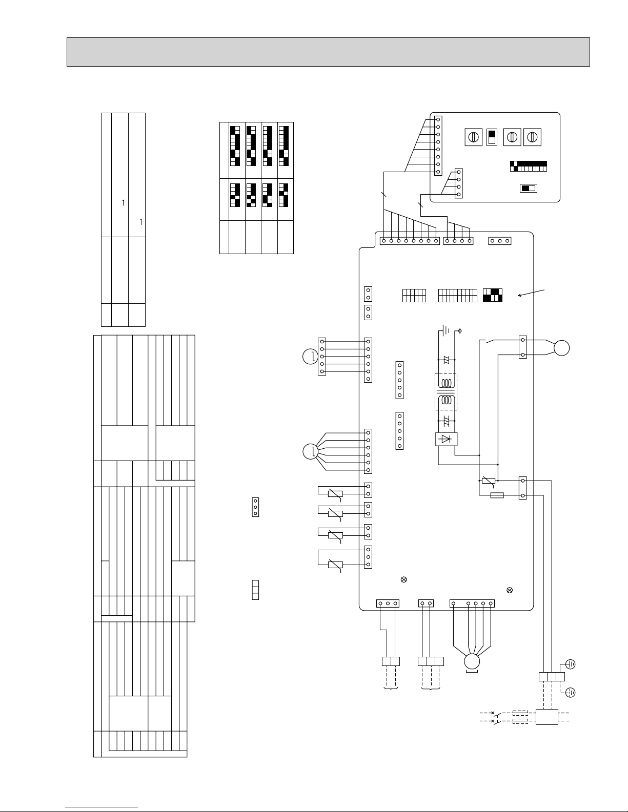
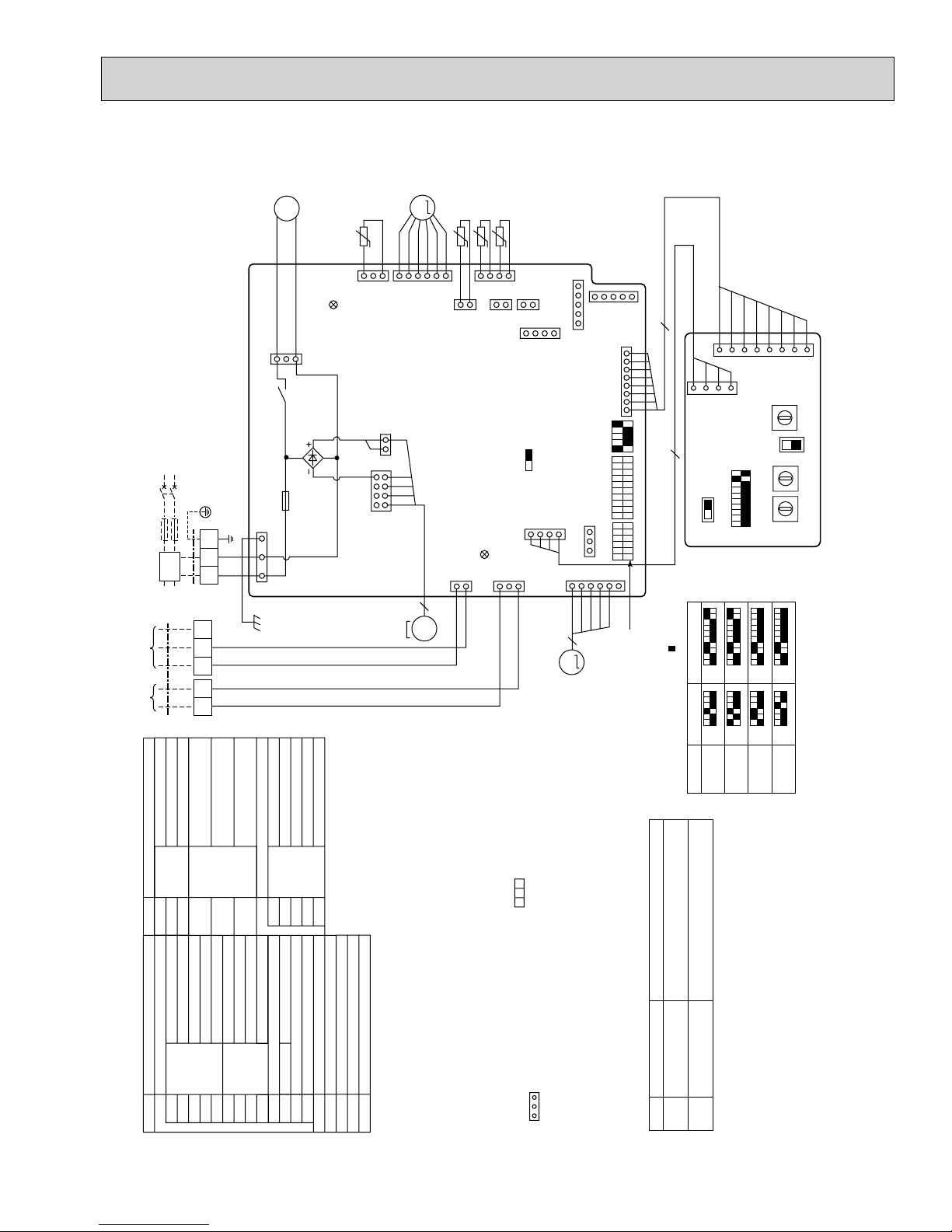
PMFY-P06NBMU-E1 PMFY-P08NBMU-E1 PMFY-P12NBMU-E1 PMFY-P15NBMU-E1
OC341F
Main power supply (Indoor unit:208-230V)
Power on Lamp is lit.
Power supply for MA-Remote controller
on Lamp is lit.
Power supply for
MA-Remote controller
Main power supply
Mark Meaning Function
LED1
LED on indoor board for service
Thermistor Room temp. detection
Symbol Name
TH21
LED2
)
)
)
77˚F/5.4k
77˚F/5.4k
,
(32˚F/15k
77˚F/5.4k
,
,
Pipe temp. detection / Liquid
(32˚F/15k
Pipe temp. detection / Gas
(32˚F/15k
Mode selection
Switch
SW1
TH22
A.B Address board
TH23Fan motor
Voltage selection
Address setting 1s digit
Address setting 10ths digit
SW5
SW11
SW12
SW14 Branch No.
<fig. +1>
SW3
ON
OFF
SW2
ON
OFF
P06
Models
10
9
8
1234567
ON
OFF
123456
ON
OFF
P08
10
9
8
1234567
ON
OFF
123456
123456
ON
OFF
P12
10
10
9
9
8
8
7
7
123456
123456
ON
OFF
123456
ON
OFF
P15
<+2>Use Copper Supply Wire.
MV
15
MM
LEV
TH21
8
8
21
CN27
2121212131
CN25
GRN
YLW
ORN
RED
BRN
WHT
YLW
ORN
BLU
RED
BRN
CN6V
(GRN)VANE
6161
CN60
(WHT)LEV
(RED)
INTAKE
(WHT)
LIQUID
OFF
ON
CN20
CN21
4
CN81
(RED)
ADDRESS
15
(GRN)
15
(WHT)
No.
BRANCH
9
8
A
7
B
6
C
5
D
4
3
E
2
F
1
0
SW14SWC
CN82
(RED) ADDRESS
81
A.B
(RED)
41
ADDRESS
411
CN42
(RED)
ADDRESS
123456
SW2
CN52
REMOTE
INDICATION
CN51
CONTROL
CENTRALLY
12345678910
SW3
T
CN43
1
(WHT)
REMOTE
SW4
X1
U
FUSE
12345
DIGIT
1s
5
6
4
4
7
3
3
8
2
2
9
1
0
SW11
230V208V
3
CN32
SWITCH
OFF
ON
CNP
(WHT)
31
31
CND
(RED)
DIGIT
10ths
5
6
7
8
9
1
0
SW12
12345678910
OFF
ON
SW1
SW5
See fig. +1
M
1~
DP
Drain pump
Vane motor
X1 Aux.relay
LED1 Power supply(I.B)
LED2 Power supply(I.B)
T Transformer
Symbol Name
Symbol Name
I.B Indoor controller board
[Legend]
Damper
Remote switch
Connector Humidifier
CN25
CN27
CN32
MF
MV
Centrally control
Remote Indication
CN51
CN52
Power supply
Drain sensor
Drain pump
Terminal
block
DS
DP
TB2
TB5 Transmission
LEV Linear expansion valve
Capacity code
Mode selection
Model selection
Switch
SW2
SW3
SW4
ZNR Varistor
FUSE Fuse (6A / 250V)
TB15 MA-Remote Controller
Note
GAS
(BLK)
CN29
DS TH23 TH22
t° t° t° t°
I.B
1. At servicing for outdoor unit, always follow the wiring diagram of outdoor unit.
2. In case of using MA-Remote controller, please connect to TB15. (Remote controller wire is non-polar.)
3. In case of using M-NET, please connect to TB5. (Transmission line is non-polar.)
4. Symbol [S] of TB5 is the shield wire connection.
5. Symbols used in wiring diagram above are, : terminal block, :connector.
6. The setting of the SW2, SW3 dip switches differs in the capacity. For the detail, refer to fig. +1.
7. Please set the switch SW5 according to the power supply voltage.
CN31
(WHT)
DRAIN
(BLU)
CN3A
3
1
ORN
ORN
1
2
TB15
TO MA-REMOTE
CONTROLLER
DC8.7-13V
LED2
(BLU)
CN2M
(M-NET)
2
1
BLU
BLU
S
M1
M2
TB5
TO OUTDOOR UNIT
BC CONTROLLER
REMOTE CONTROLLER
1
(SHIELD)
DC24-30V
11
FAN
(WHT)
6
3
3~
MS
MF
POWER SUPPLY
(15A)
~ / N 208-230V 60Hz
BREAKER
LED1
FUSE
(15A)
RED
TB2
<+2>
BLU
GRN / YLW
L1
L2
PULL BOX
GR
TO NEXT INDOOR UNIT
PMFY-P06NBMU-E#2 PMFY-P08NBMU-E#2 PMFY-P12NBMU-E#2 PMFY-P15NBMU-E#2
OC341F
PMFY-P06NBMU-ER3 PMFY-P08NBMU-ER3 PMFY-P12NBMU-ER3 PMFY-P15NBMU-ER3
PMFY-P06NBMU-ER4 PMFY-P08NBMU-ER4 PMFY-P12NBMU-ER4 PMFY-P15NBMU-ER4
POWER SUPPLY
~ / N
208-230V 60Hz
)
(15A
BREAKER
)
(15A
FUSE
PULL BOX
TO NEXT
INDOOR
UNIT
TO OUTDOOR UNIT
BC CONTROLLER
REMOTE CONTROLLER
DC24-30V
REMOTE
TO MA-
CONTROLLER
DC8.7-13V
TB15
TB5
GR
L1 L2
TB2
S
M1 M2
2
1
)
/
YLW
(SHIELD)
)
I.B
GRN
BLU
RED
BLK
1
)
WHT
DRAIN
(
CNMF1
1
2
)
WHT
(
CNMF2
BRN
)
WHT
(
1357
M
LEV
BLU
ORN
YLW
RED
WHT
6
1
)
WHT
LEV
(
CN60
CN2M
5
BLU
3~
MF
MS
TH21
t°t°t°
2
1
)
RED
(
CN20
INTAKE
)
BLU
(
M-NET
2
1
BLU
TH23
4
LED2
CN25
CN3A
1
ORN
TH22
1
1
)
WHT
(
SWE
)
BLU
REMOCON
(
3
ORN
)
WHT
CN44
(
LIQUID/GAS
212
4
)
WHT
(
CN41
ON OFF
CN42
4
CN6V1
)
RED
(
CN27
1
HA
)
RED
(
ADDRESS
1
)
GRN
(
1
5
)
WHT
CENTRALLY
CN51 (
31
1
VANE
RED
BRN
5
M
)
WHT
CN32 (
ORN
5
1
)
GRN
(
CN52
REMOTE
INDICATION
81
)
CONTROL
RED
ADDRESS
CN81 (
SW4
12345
SW3
12345678910
REMOTE SWITCH
SW2
123456
6
YLW
GRN
MV
*See fig. 1
8
8
4
1
RED)
CN43
(
ADDRESS
4
230V208V
SW1
SW5
12345678910
RED)
(
ADDRESS
SW14
SW11
SW12
CN82
3
2
1
0
F
SWC
2
1
0
2
1
0
1
5
4
6
7
8
9
No.
A
B
C
E
D
BRANCH
3
4
5
6
1s
7
9
8
DIGIT
3
4
5
6
7
10ths
9
DIGIT
8
A.B
10
10
10
9
8
1234567
ON
OFF
123456
ON
OFF
P12
10
9
9
8
8
7
7
123456
123456
ON
OFF
123456
123456
ON
OFF
P15
<2> Use Copper Supply Wire.
<fig. 1>
SW3
ON
OFF
SW2
ON
OFF
P06
Models
9
8
1234567
ON
OFF
123456
ON
OFF
P08
M
DP
BLU
1~
BLU
DS
t°
3
LED1
CN31
)
YLW
CNP
(
1
D.U.M
3
X1
~339V
DC311
FUSE
513
DSA
ZNR01
U
ZNR02
U
8642
)
BLK
CND (
)
32°F/15k, 77°F/5.4k
32°F/15k, 77°F/5.4k
Power supply
Terminal
block
Thermistor Room temp. detection
Symbol Name
TB15 MA-Remote Controller
TB2
TB5 Transmission
TH21
Damper
Remote switch
Connector Humidifier
CN25
CN27
CN32
Symbol Name
I.B Indoor controller board
[Legend]
32°F/15k, 77°F/5.4k
(
Pipe temp. detection / Liquid
(
Pipe temp. detection / Gas
(
Mode selection
Switch
TH23
A.B Address board
DRAIN UP MACHINE(TEST MODE)
Capacity code
Mode selection
Model selection
Switch
SW2
SW3
SW4
SWE
SW1
ZNR Varistor
TH22
Centrally control
Remote Indication
CN51
CN52
Voltage selection
Address setting 1s digit
Address setting 10ths digit
SW5
SW11
SW12
SW14 Branch No.
)
)
)
I.B
I.B
Drain pump
(
(
T6.3AL 250V
(
LED1 Power supply
LED2 Power supply
X1 Aux.relay
FUSE Fuse
Fan motor
Vane motor
MF
MV
Drain sensor
Drain pump
LEV Linear expansion valve
DS
DP
Main power supply (Indoor unit:208-230V)
Power on Iamp is lit
Main power supply
Mark Meaning Function
LED1
Note
1. At servicing for outdoor unit, always follow the wiring diagram
of outdoor unit.
2. In case of using MA-Remote controller, please connect to
TB15. (Remote controller wire is non-polar.)
3. In case of using M-NET, please connect to TB5.
(Transmission line is non-polar.)
4. Symbol [S] of TB5 is the shield wire connection.
5. Symbols used in wiring diagram above are, : terminal
block, :connector.
6. The setting of the SW2, SW3 dip switches differs in the capacity.
For the detail, refer to fig. 1.
LED on indoor board for service
7. Please set the switch SW5 according to the power supply
voltage.
12
Power supply for MA-Remote controller
on Iamp is lit
Power supply for
MA-Remote controller
LED2
Note
1.At servicing for outdoor unit, always follow the wiring diagram of outdoor unit.
2.In case of using MA-Remote controller, please connect to TB15.
(Remote controller wire is non-polar.)
3.In case of using M-NET, please connect to TB5.
(Transmission line is non-polar.)
4.Symbol [S] of TB5 is the shield wire connection.
5.Symbols used in wiring diagram above are, : terminal block,
:connector.
6.The setting of the SW2, SW3 dip switches differs in the capacity for the detail,
refer to the fig :
1.
7.Please set the switch SW5 according to the power supply voltage.
CN51
CN52
SW2
SW3
SW4
SWE
A.B Address board
SW1
SW5
SW11
SW12
Mode selection
Voltage selection
Address setting 1s digit
Address setting 10ths digit
SW14 Branch No.
Centrally control
Remote Indication
Switch
Switch
Capacity code
Mode selection
Model selection
DRAIN UP MACHINE(TEST MODE)
X1 Aux.relay
Drain pump
FUSE Fuse (T6.3AL 250V)
LED1 Power supply (I.B)
LED2 Power supply (I.B)
TH21
MF
MV
Thermistor Room temp. detection
(32°F/15k, 77°F/5.4k)
Pipe temp. detection / Liquid
(32°F/15k, 77°F/5.4k)
Pipe temp. detection / Gas
(32°F/15k, 77°F/5.4k)
LEV Linear expansion valve
TH22
TH23
Fan motor
Vane motor
TB15 MA-Remote Controller
[Legend]
Symbol Name
I.B Indoor controller board
CN25
CN27
CN32
Connector Humidifier
Damper
Remote switch
Symbol Name
DS
DP
Drain sensor
Drain water lifting-up mech.
TB2
TB5 Transmission
Terminal
block
Power supply
Models
P06
P08
P12
P15
SW2
123456
ON
OFF
123456
ON
OFF
123456
ON
OFF
123456
ON
OFF
SW3
1234567
ON
OFF
1234567
ON
OFF
123456
ON
OFF
123456
7
7
8
8
8
8
9
9
9
9
10
10
10
10
ON
OFF
<fig : 1>
Mark Meaning Function
Power supply for
MA-Remote controller
Main power supply (Indoor unit:208-230V)
Power on Iamp is lit
LED on indoor board for service
LED1
Main power supply
Power supply for MA-Remote controller
on Iamp is lit
LED2
<2> Use Copper Supply Wire.
The black square ( ) indicates
a switch position.
SWE
ON OFF
ON
OFF
GR
0
1
2
3
4
5
6
7
8
9
A
B
C
D
E
F
0
1
2
3
4
5
6
7
8
9
0
1
2
3
4
5
6
7
8
9
10ths
DIGIT
1s
DIGIT
BRANCH
No.
SW12 SW11
SW14
CN2M
(BLU)
M-NET
CNP
(
YLW)
DUM
CN3A
(BLU)
MA REMOCON
TB5
(SHIELD)
M1 M2
TB2
TB15
1
S
TH23
TH22
CN20
(RED)
INTAKE
CN60
(WHT)
LEV
CN52
(GRN)
REMOTE
INDICATION
CN6V1
(GRN)
VANE
TH21
CNMF2
(WHT)
CNMF1
(WHT)
CN31
(WHT)
DRAIN
CN44
(WHT)
LIQUID
/
GAS
CN25
(WHT)
CN27
(RED)
ADDRESS
CN81
(RED)
CN42
(RED)
ADDRESS
CN32
(WHT)
REMOTE SWITCH
X1
CND
(BLK)
FUSE
CN51
(WHT)
CENTRALLY
CONTROL
CN41
(WHT)
HA
4
8
5
5
LEV
M
DS
DP
t°
t°
t°
t°
2
L1 L2
12345678910
SW3
123456
SW2
12345
SW4
81
5
1
513
6
1
6
1
5
1
4
1
2
1
2
1
2
1
4
1
1
3
3
1
3
1
31
2
1
2
1
1
4
1357
864 2
I.B
M
1~
M
MS
3~
PULL BOX
FUSE
(15A)
BREAKER
(15A)
POWER SUPPLY
~
/ N
208-230V 60Hz
TO NEXT
INDOOR
UNIT
BLU
BRN
ORN
YLW
RED
WHT
SWC
12345678910
SW1
SW5
230V208V
(RED)
ADDRESS
CN82
(RED)
ADDRESS
CN43
A.B
8
1
4
1
TO MA-
REMOTE
CONTROLLER
DC8.7-13V
TO OUTDOOR UNIT
BC CONTROLLER
REMOTE CONTROLLER
DC24-30V
RED
BLU
GRN
/
YLW
MF
MV
ORN
*See fig : 1
ORN
BLU
BLU
BLU
BLU
LED2
LED1
GRN
YLW
ORN
RED
BRN
BLK
PMFY-P06NBMU-ER5 PMFY-P08NBMU-ER5 PMFY-P12NBMU-ER5 PMFY-P15NBMU-ER5
OC341F
13
 Loading...