

Mitsubishi PMFY-P32VBM-E, PMFY-P20VBM-E, PMFY-P50VBM-E, PMFY-P25VBM-E, PMFY-P40VBM-E Installation Manual
...
Air-Conditioners For Building Application
INDOOR UNIT
PMFY-P·VBM-E
INSTALLATION MANUAL
For safe and correct use, please read this installation manual thoroughly before installing the air-conditioner
unit.
INSTALLATIONSHANDBUCH
Zum sicheren und ordnungsgemäßen Gebrauch der Klimaanlage das Installationshandbuch gründlich
durchlesen.
MANUEL D’INSTALLATION
Veuillez lire le manuel d’installation en entier avant d’installer ce climatiseur pour éviter tout accident et vous
assurer d’une utilisation correcte.
INSTALLATIEHANDLEIDING
Voor een veilig en juist gebruik moet u deze installatiehandleiding grondig doorlezen voordat u de airconditioner
installeert.
MANUAL DE INSTALACIÓN
Para un uso seguro y correcto, lea detalladamente este manual de instalación antes de montar la unidad de
aire acondicionado.
MANUALE DI INSTALLAZIONE
Per un uso sicuro e corretto, leggere attentamente questo manuale di installazione prima di installare il condizionatore
d’aria.
E°XEIPI¢IO O¢H°IøN E°KATA™TA™H™
°И· ·ЫК¿ПВИ· О·И ЫˆЫЩ‹ ¯Ъ‹ЫЛ, ·Ъ·О·ПВ›ЫЩВ ‰И·‚¿ЫВЩВ ЪФЫВ¯ЩИО¿ ·˘Щfi ЩФ ВБ¯ВИЪ›‰ИФ ВБО·Щ¿ЫЩ·ЫЛ˜
ЪИУ ·Ъ¯›ЫВЩВ ЩЛУ ВБО·Щ¿ЫЩ·ЫЛ ЩЛ˜ МФУ¿‰·˜ ОПИМ·ЩИЫМФ‡.
MANUAL DE INSTALAÇÃO
Para segurança e utilização correctas, leia atentamente este manual de instalação antes de instalar a unidade
de ar condicionado.
For use with the R410A, R407C & R22
Bei Verwendung von R410A, R407C & R22
A utiliser avec le R410A, R407C et le R22
Bij gebruik van R410A, R407C & R22
Para utilizar con el R410A, R407C y el R22
Uso del refrigerante R410A, R407C e R22
FOR INSTALLER
FÜR INSTALLATEURE
POUR L’INSTALLATEUR
VOOR DE INSTALLATEUR
PARA EL INSTALADOR
PER L’INSTALLATORE
°π∞ ∞À∆√¡ ¶√À ∫∞¡∂π ∆∏¡ ∂°∫∞∆∞™∆∞™∏
PARA O INSTALADOR
°È· ¯Ú‹ÛË Ì ٷ R410A, R407C Î·È R22
Para utilizaçao com o R410A, R407C e o R22
R410A, R407C ve R22 ile beraber kullanmak için
Для использования с моделями R410A, R407С и R22
English
Deutsch
Français
Nederlands
Español
Italiano
∂ППЛУИО¿
Português
MONTAJ ELK‹TABI
Emniyetli ve do¤ru biçimde nas›l kullan›laca¤›n› ö¤renmek için lütfen klima cihaz›n› monte etmeden önce bu
elkitab›n› dikkatle okuyunuz.
РУКОВОДСТВО ПО УСТАНОВКЕ
Для осторожного и правильного использования прибора необходимо тщательно ознакомиться с данным
руководством по установке до выполнения установки кондиционера.
MONTÖR ‹Ç‹N
Türkçe
ДЛЯ УСТАНОВИТЕЛЯ
Русский
Contents
ELV
1. Safety precautions ................................................................................... 2
2. Installing the indoor unit ........................................................................... 2
3. Refrigerant pipe and drain pipe ............................................................... 4
1. Safety precautions
s Before installing the unit, make sure you read all the “Safety precau-
tions”.
s Please report to your supply authority or obtain their consent before
connecting this equipment to the power supply system.
Warning:
Describes precautions that must be observed to prevent danger of injury or
death to the user.
Caution:
Describes precautions that must be observed to prevent damage to the unit.
After installation work has been completed, explain the “Safety Precautions,” use,
and maintenance of the unit to the customer according to the information in the Operation Manual and perform the test run to ensure normal operation. Both the Installation Manual and Operation Manual must be given to the user for keeping. These
manuals must be passed on to subsequent users.
Warning:
• Ask the dealer or an authorized technician to install the air conditioner.
• Install the unit at a place that can withstand its weight.
• Use the specified cables for wiring.
• Use only accessories authorized by Mitsubishi Electric and ask the dealer or
an authorized technician to install them.
• Do not touch the heat exchanger fins.
• Install the air conditioner according to this Installation Manual.
Caution:
• Do not use the existing refrigerant piping, when use R410A or R407C refrig-
erant.
• Use ester oil, either oil or alkylbenzene (small amount) as the refrigerator oil
to coat flares and flange connections, when use R410A or R407C refrigerant.
• Do not use the air conditioner where food, pets, plants, precision instruments,
or artwork are kept.
• Do not use the air conditioner in special environments.
2. Installing the indoor unit
4. Electrical work .......................................................................................... 6
5. Installing the grille .................................................................................... 7
6. Test run (Fig. 6-1) ..................................................................................... 9
: Indicates an action that must be avoided.
: Indicates that important instructions must be followed.
: Indicates a part which must be grounded.
: Indicates that caution should be taken with rotating parts.
: Indicates that the main switch must be turned off before servicing.
: Beware of electric shock.
: Beware of hot surface.
: At servicing, please shut down the power supply for both the Indoor and
Outdoor Unit.
Warning:
Carefully read the labels affixed to the main unit.
• Have all electric work done by a licensed electrician according to local regulations.
• If the air conditioner is installed in a small room, measures must be taken to
prevent the refrigerant concentration from exceeding the safety limit even if
the refrigerant should leak.
• The cut face punched parts may cause injury by cut, etc. The installers are
requested to wear protective equipement such as gloves, etc.
• Ground the unit.
• Install an leak circuit breaker, as required.
• Use power line cables of sufficient current carrying capacity and rating.
• Use only a circuit breaker and fuse of the specified capacity.
• Do not touch the switches with wet fingers.
• Do not touch the refrigerant pipes during and immediately after operation.
• Do not operate the air conditioner with the panels and guards removed.
• Do not turn off the power immediately after stopping operation.
1 2
3
5
Fig. 2-1
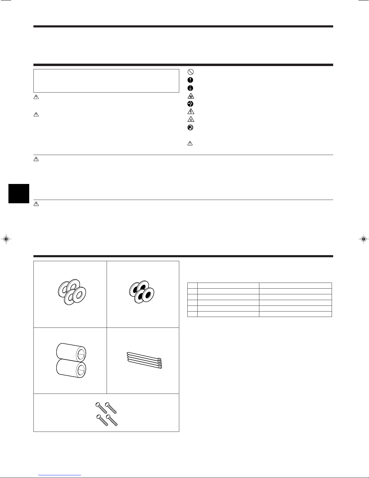
2.1. Check the indoor unit accessories (Fig. 2-1)
The indoor unit should be supplied with the following spare parts and accessories
(contained in the inside of the intake grille).
Accessory name Q’ty
1 Washer 4 pcs
2 Washer (with insulation) 4 pcs
3 Pipe cover 2 pcs
4 Band 4 pcs
5 Screw 4 pcs M5 × 0.8 × 30
4
2
2. Installing the indoor unit
C
A
D
AB
110
230
E
F
230
A
24769
53
17.517.5
2020
2828
45
20
45
20
340
3
430 2470
1
26
74.5
20
26
74.5
20
759
811
3
960
2
1000
1
4
A
C
D
E
C
*1
B
Min. 20 Min. 30
D
E
F
G
340
811
K
L
M
J
H
I
Fig. 2-2
Fig. 2-3
Fig. 2-4
Fig. 2-5
Fig. 2-6
(mm)
(mm)
(mm)
(mm)
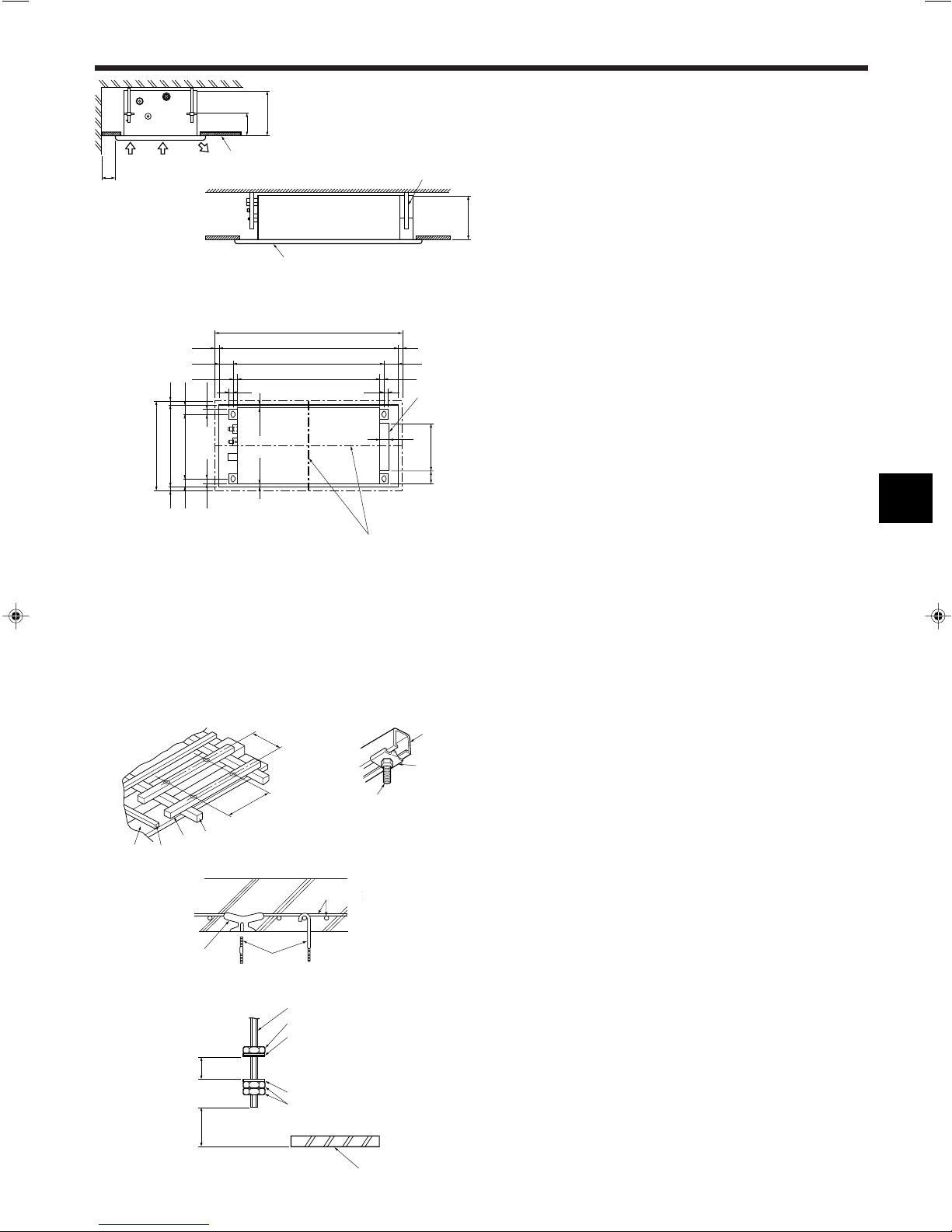
2.2. Service space (Fig. 2-2)
• The dimensions of ceiling opening can be regulated within the range shown in
following diagram; so center the main unit against the opening of ceiling, ensuring
that the respective opposite sides on all sides of the clearance between them becomes identical.
A Air intake
B Air outlet
C Ceiling panel
D Min. 200 mm
E Suspension bolts W3/8 or M10
F Grille
2.3. Ceiling openings and suspension bolt installation
locations (Fig. 2-3)
• Make an opening in the ceiling 430 mm × 960 mm in size. This functions as a check
window and will be needed later during servicing.
• If the dimensions are not accurate, when the grille is installed there may be gaps
between it and the indoor unit. This may result in dripping water or other problems.
• When deciding on placement, consider carefully the space around the ceiling and
make your measurements generous.
• Ceiling types and building construction differ. Therefore you should consult with the
builder and decorator.
A The centers of the ceiling opening and the indoor unit should be aligned.
1 Outer side of grille
2 Ceiling opening
3 Bolt pitch
4 Electric box
• Using the installation template (top of the package) and the gauge (supplied as an
accessory with the grille), make an opening in the ceiling so that the main unit can
be installed as shown in the diagram. (The method for using the template and the
gauge are shown.)
• Use M10 (3/8") suspension bolts.
* Suspension bolts are to be procured at the field.
• After suspending the indoor unit, you will have to connect the pipes and wiring
above the ceiling. Once the location has been fixed and the direction of the pipes
has been determined, place the refrigerant and drainage pipes, the wiring for the
remote controller, and the wiring that connects the indoor and outdoor units in their
desired locations before suspending the indoor unit. This is especially important in
cases where the ceiling is already in existence.
1 Wooden structures (Fig. 2-4)
• Use tie beams (single storied houses) or second floor beams (two story houses) as
reinforcing members.
• Wooden beams for suspending air conditioners must be sturdy and their sides
must be at least 6 cm long if the beams are separated by not more than 90 cm and
their sides must be at least 9 cm long if the beams are separated by as much as
180 cm. The size of the suspension bolts should be ø10 mm (3/8"). (The bolts do
not come with the unit.)
• Use channel, duct and other parts procured locally to suspend the indoor unit.
2 Ferro-concrete structures (Fig. 2-5)
Secure the suspension bolts using the method shown, or use steel or wooden hangers, etc. to install the suspension bolts.
D Ceiling panel
E Rafter
F Beam
G Roof beam
H Use inserts rated at 100-150 kg each (pro-
cure locally)
I Suspension bolts M10 (3/8") (procure lo-
cally)
J Steel reinforcing rod
K C channel
L Channel suspension bracket
M M10 suspension bolt
2.4. Unit suspension procedures (Fig. 2-6)
Procure 3/8" bolts or M10 bolts locally.
• Adjust the length of the bolt’s protrusion from the ceiling surface beforehand.
*1. When using an extra upper nut in suspending the unit, in some cases you may
have to add it later.
A Suspension bolt
B Ceiling panel
C Nut
D Washer (with insulation) 2
E Washer (without insulation) 1
3
 Loading...