

MITSUBISHI PM75CS1D060 Technical data
PM75CS1D060
MITSUBISHI <INTELLIGENT POWER MODULES>
PM75CS1D060
FLAT-BASE TYPE
INSULATED PACKAGE
FEATURE
Inverter + Drive & Protection IC
• 3 phase 75A/600V CSTBT
TM
(The Current senser and the thermal senser with a build-in
TM
CSTBT
.)
• Monolithic gate drive & protection logic
• Detection, protection & status indication circuits for, shortcircuit, over-temperature & under-voltage
APPLICATION
General purpose inverter, servo drives and other motor controls
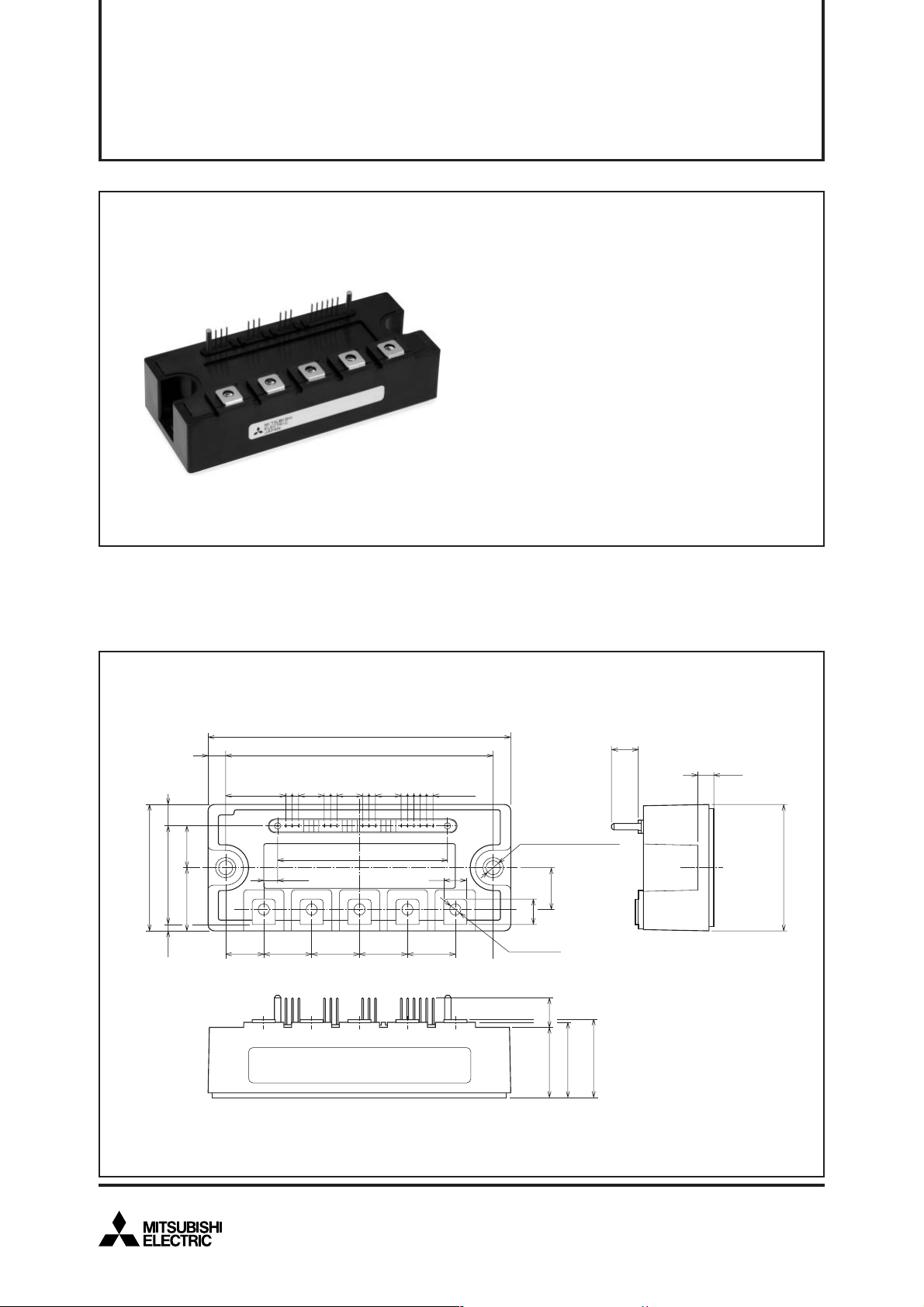
PACKAGE OUTLINES Dimensions in mm
120
7
23.79
16.525
50
39 8.52.5
15 19 19 19
2-2.54
10.16 10.16
14
5.57
WVUNP
±0.3
106
2-2.54
2-2.54
10.16
71015
67.4
LABEL
5-2.54
2-φ5.5
MOUNTING HOLES
9
16.5
(10)
19
5-M4 NUT
11.6
28
30
1
+
0.5
–
31.5
10.6
Te rminal code
1. VWPC
2. WP
3. VWP1
4. VVPC
5. VP
6. VVP1
7. VUPC
8. UP
9. VUP1
6.5
50
11. VN1
12. WN
13. VN
14. UN
15. Fo
Nov. 2008
1
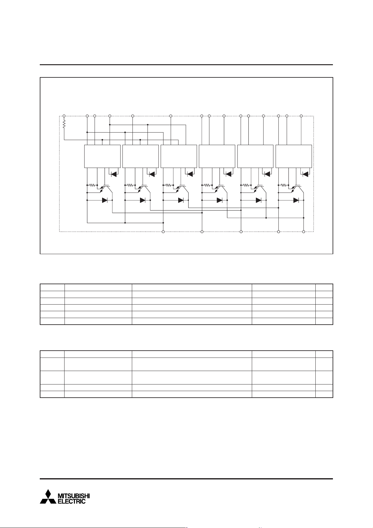
INTERNAL FUNCTIONS BLOCK DIAGRAM
MITSUBISHI <INTELLIGENT POWER MODULES>
PM75CS1D060
FLAT-BASE TYPE
INSULATED PACKAGE
Rfo = 1.5kΩ
Fo
Rfo
NC
V
Gnd In Fo Vcc
Gnd Si Out OT
V
W
N
N1
V
N
Gnd In Fo Vcc
Gnd Si Out OT
U
N
Gnd In Fo Vcc
Gnd Si Out OT
NWVUP
W
P
V
WPC
Gnd In Vcc
Gnd Si Out OT
V
WP1
V
P
V
VPC
Gnd In Vcc
Gnd Si Out OT
V
VP1
U
P
V
UPC
Gnd In Vcc
Gnd Si Out OT
V
UP1
MAXIMUM RATINGS (Tj = 25°C, unless otherwise noted)
INVERTER PART
Symbol Parameter Condition Unit
VCES
±IC
±ICP
PC
Tj
Collector-Emitter Voltage
Collector Current
Collector Current (Peak)
Collector Dissipation
Junction Temperature
V
D = 15V, VCIN = 15V
T
C = 25°C (Note-1)
T
C = 25°C
T
C = 25°C (Note-1)
*: Tc measurement point is just under the chip.
Ratings
600
75
150
378
–20 ~ +150
V
A
A
W
°C
CONTROL PART
Symbol Parameter Condition Ratings Unit
VD
VCIN
FO
V
IFO
Supply Voltage
Input Voltage
Fault Output Supply Voltage
Fault Output Current
Applied between : V
Applied between : UP-VUPC, VP-VVPC, WP-VWPC
Applied between : FO-VNC
Sink current at FO terminals
UP1-VUPC, VVP1-VVPC
VWP1-VWPC, VN1-VNC
UN • VN • WN-VNC
2
20
20
20
20
Nov. 2008
V
V
V
mA
TOTAL SYSTEM
Symbol
V
CC(PROT)
V
CC(surge)
Tstg
Viso
Supply Voltage Protected by
SC
Supply Voltage (Surge)
Storage Temperature
Isolation Voltage
Parameter
THERMAL RESISTANCES
Symbol
Rth(j-c)Q
Rth(j-c)F
Rth(c-f)
Junction to case Thermal
Resistances
Contact Thermal Resistance
Parameter
MITSUBISHI <INTELLIGENT POWER MODULES>
Condition
V
D = 13.5 ~ 16.5V
Inverter Part, T
Applied between : P-N, Surge value
60Hz, Sinusoidal, Charged part to Base, AC 1 min.
Inverter IGBT part (per 1 element) (Note-1)
Inverter FWDi part (per 1 element) (Note-1)
Case to fin, (per 1 module)
Thermal grease applied (Note-1)
j = +125°C Start
Condition
PM75CS1D060
FLAT-BASE TYPE
INSULATED PACKAGE
Ratings
400
500
–40 ~ +125
2500
Limits
Min.
—
—
—
Typ. Max.
0.33
—
0.55
—
0.046
—
Unit
V
V
°C
V
rms
Unit
°C/W
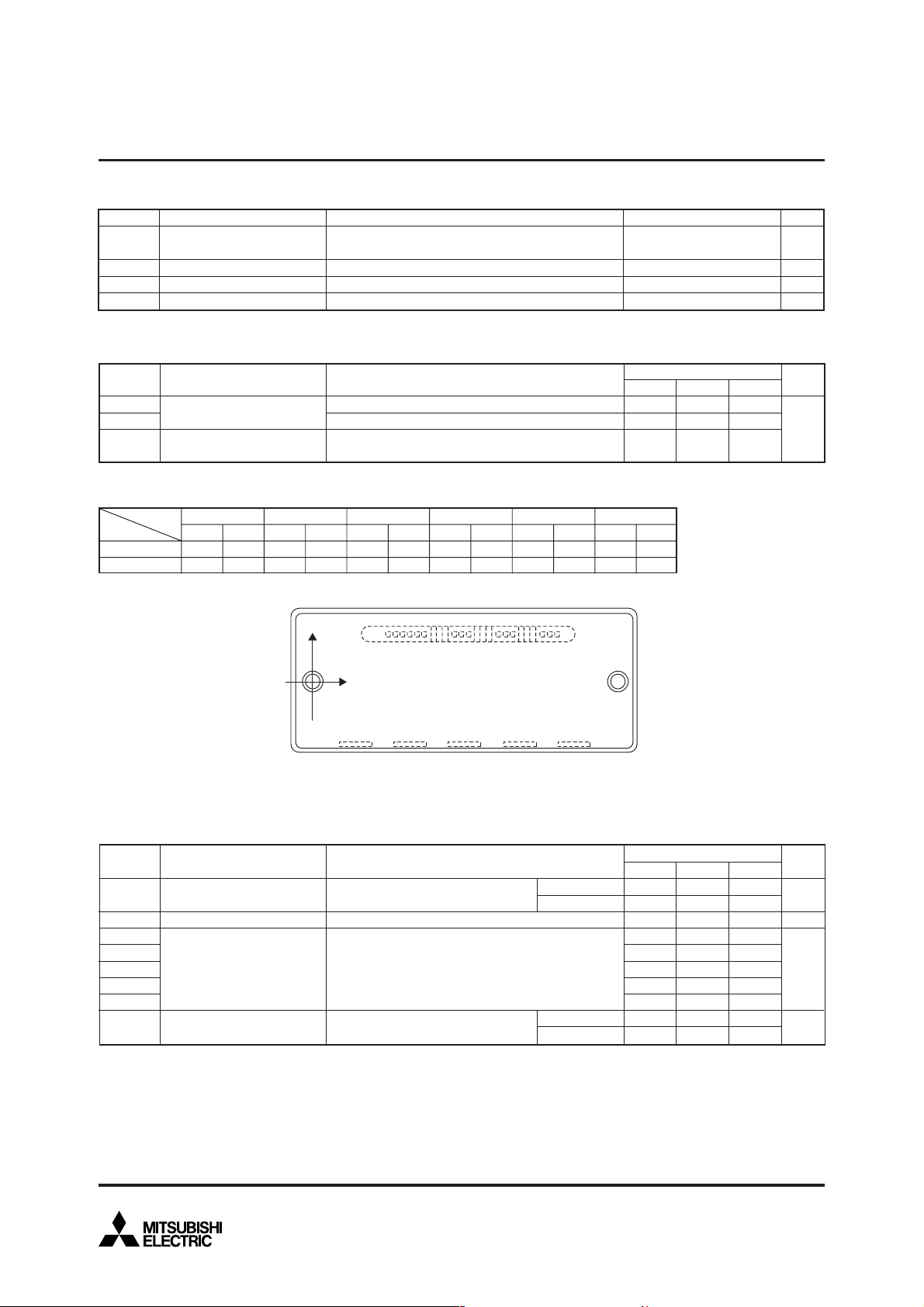
(Note-1) Tc (under the chip) measurement point is below.
axis
arm
X
Y
IGBT
21.4
4.6
UP
FWDi
21.4
–5.2
VP WP UN VN WN
FWDi
IGBT
FWDi
IGBT
FWDi
IGBT
36.0
36.0
90.0
90.0
65.0
65.0
–9.9
–0.4
–5.2
4.6
–5.2
4.6
Bottom view
Y
X
PNU VW
ELECTRICAL CHARACTERISTICS (Tj = 25°C, unless otherwise noted)
INVERTER PART
Symbol
CE(sat)
V
VEC
ton
trr
tc(on)
toff
tc(off)
ICES
Parameter
Collector-Emitter Saturation
Voltage
FWDi Forward Voltage
Switching Time
Collector-Emitter Cutoff
Current
D = 15V, IC = 75A
V
V
CIN = 0V, Pulsed (Fig. 1)
–I
C = 75A, VD = 15V, VCIN = 15V (Fig. 2)
D = 15V, VCIN = 0V↔15V
V
V
CC = 300V, IC = 75A
T
j = 125°C
Inductive Load (Fig. 3,4)
VCE = V
CES
, VD = 15V
Condition
(Fig. 5)
IGBT
51.0
–0.4
FWDi
51.0
–9.9
T
j = 25°C
T
j = 125°C
T
j = 25°C
T
j = 125°C
(unit : mm)
FWDi
IGBT
76.0
76.0
–9.9
–0.4
Min. Typ. Max.
—
—
—
0.4
—
—
—
—
—
—
Limits
1.80
1.85
1.85
0.8
0.3
0.4
1.4
0.3
—
—
2.40
2.50
2.80
1.8
0.6
1.0
2.4
0.6
1
10
Unit
V
V
µs
mA
Nov. 2008
3
 Loading...