

Mitsubishi PM10CSJ060 Datasheet
MITSUBISHI INTELLIGENT POWER MODULES
PM10CSJ060
FLA T-BASE TYPE
INSULA TED P ACKAGE
A
C
D
N
Q
Q
Q
1
234 5678 91011121314151617
18
H J FG
S - DIA.
(2 TYP.)
L
19 20 21 22 23
PNUVW
MMMM
E
B
2.0 X 0.5 MM TAB (5 TYP.)
0.6 X 0.4 MM TAB (18 TYP.)
T
NC
GND
CC
V
FOWNVNU
WN
UNVNWNFOVN1V
C
T
N
B
T
GND
OUNSUNOVNSVNOWNS
(14 TYP.)
R (2 TYP.)
P
WPC
V
SIGND GND
V
UPC
1.
O
UF
2.
U
P
3.
V
4.
UPI
V
5.
V
6.
7.
8.
9.
10.
11.
12.
VF
V
V
V
WF
W
V
VPC
O
P
VPI
WPC
P
WPI
O
13.
14.
15.
16.
17.
18.
19.
20.
21.
22.
23.
NC
V
V
N1
U
N
V
N
W
N
F
O
P
N
U
V
W
Description:
Mitsubishi Intelligent Power Modules are isolated base modules designed for power switching applications operating at frequencies to
20kHz. Built-in control circuits pro-
K
U
UPI
UPC
VPI
VPC
WPI
V
WFOWP
V
V
VFOVP
V
V
UFOUP
vide optimum gate drive and protection for the IGBT and free-wheel
diode power devices.
Features:
u Complete Output Power
Circuit
CC
V
FOIN
OUT
CC
V
FOIN
SIGND GND
OUT
CC
V
FOIN
SIGND GND
OUT
u Gate Drive Circuit
u Protection Logic
– Short Circuit
– Over Current
– Over Temperature
– Under Voltage
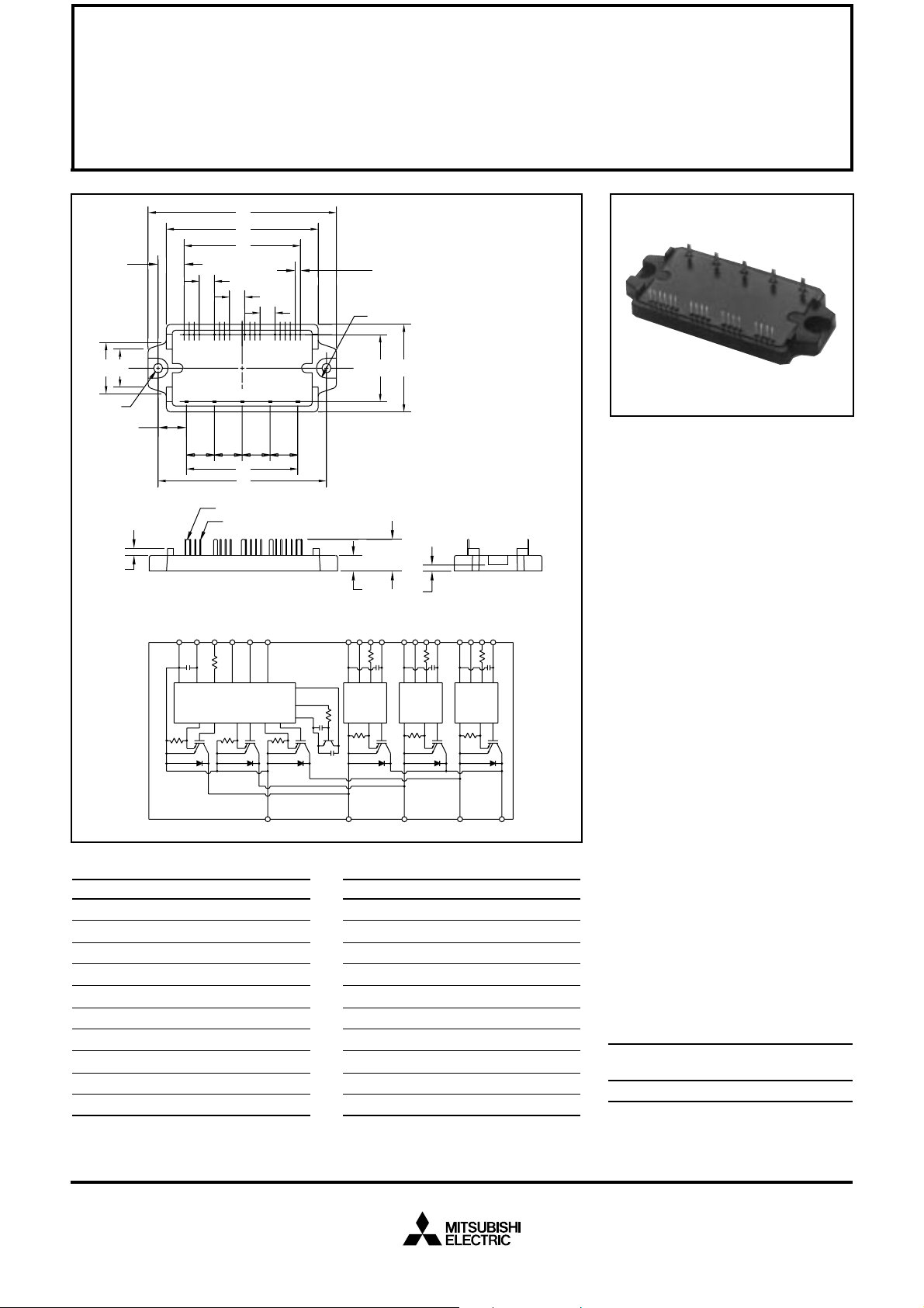
Outline Drawing and Circuit Diagram
Dimensions Inches Millimeters
A 3.72±0.04 94.5±1.0
B 3.33±0.02 84.5±0.5
C 2.99 76.0
D 2.300±0.02 58.42±0.5
E 2.20±0.02 56.0±0.5
F 1.73±0.04 44.0±1.0
G 1.32±0.03 33.6±0.8
H 1.01 25.7
J 0.75 19.0
K 0.71±0.04 18.0±1.0
P
UVWN
Dimensions Inches Millimeters
L 0.561 14.25
M 0.55±0.01 14.0±0.25
N 0.513 13.04
P 0.31±0.02 8.0±0.5
Q 0.300 7.62
R 0.20 Rad. Rad. 5.0
S 0.18 Dia. Dia. 4.5
T 0.14 3.5
U 0.13±0.02 3.2±0.5
V 0.100±0.01 2.54±0.25
Applications:
u Inverters
u UPS
u Motion/Servo Control
u Power Supplies
Ordering Information:
Example: Select the complete
part number from the table below
-i.e. PM10CSJ060 is a 600V,
10 Ampere Intelligent Power Module.
Type Current Rating V
Amperes Volts (x 10)
PM 10 60
CES
Sep.1998

MITSUBISHI INTELLIGENT POWER MODULES
PM10CSJ060
FLA T-BASE TYPE
INSULA TED PACKAGE
Absolute Maximum Ratings, Tj = 25°C unless otherwise specified
Ratings Symbol PM10CSJ060 Units
Power Device Junction Temperature T
Storage T emperature T
Case Operating Temperature T
j
stg
C
Mounting Torque, M4 Mounting Screws — 0.98 ~ 1.47 N · m
Module Weight (Typical) — 60 Grams
Supply Voltage Protected by OC and SC (VD = 13.5 - 16.5V, Inverter Part) V
Isolation Voltage (Main Terminal to Baseplate, AC 1 min.) V
CC(prot.)
iso
Control Sector
Supply Voltage (Applied between V
UP1-VUPC
Input Voltage (Applied between UP-V
Fault Output Supply Voltage
(Applied between UFO-V
Fault Output Current (Sink Current of UFO, VFO, WFO and FO Terminal) I
UPC
, VP-V
, V
VP1-VVPC
VPC
UPC
, WP-V
, VFO-V
, V
WP1-VWPC
, UN · VN · WN-VNC)V
WPC
VPC
, VN1-VNC)V
, WFO-V
WPC
, FO-VNC)
D
CIN
V
FO
FO
-20 to 150 °C
-40 to 125 °C
-20 to 100 °C
400 Volts
2500 Vrms
20 Volts
20 Volts
20 Volts
20 mA
IGBT Inverter Sector
Collector-Emitter Voltage (VD = 15V , V
Collector Current, (TC = 25°C) I
Peak Collector Current, (TC = 25°C) I
Supply Voltage (Applied between P - N) V
Supply Voltage, Surge (Applied between P - N) V
Collector Dissipation P
= 15V) V
CIN
CC(surge)
CES
C
CP
CC
C
600 Volts
10 Amperes
20 Amperes
450 Volts
500 Volts
39 Watts
Sep.1998
 Loading...