

MITSUBISHI PM100RSE060 Technical data
查询PM100RSE060供应商
MITSUBISHI <INTELLIGENT POWER MODULES>
MITSUBISHI <INTELLIGENT POWER MODULES>
PM100RSE060
PM100RSE060
APPLICATION
General purpose inverter, servo drives and other motor controls
FEATURE
a) Adopting new 4th generation planar IGBT chip, which per-
formance is improved by 1µm fine rule process.
For example, typical V
b) Using new Diode which is designed to get soft reverse
recovery characteristics.
•3φ 100A, 600V Current-sense IGBT for 15kHz switching
• 30A, 600V Current-sense regenerative brake IGBT
• Monolithic gate drive & protection logic
• Detection, protection & status indication circuits for overcurrent, short-circuit, over-temperature & under-voltage
• Acoustic noise-less 11kW class inverter application
PM100RSE060
FLAT-BASE TYPE
FLAT-BASE TYPE
INSULATED PACKAGE
INSULATED PACKAGE
CE(sat)=1.7V
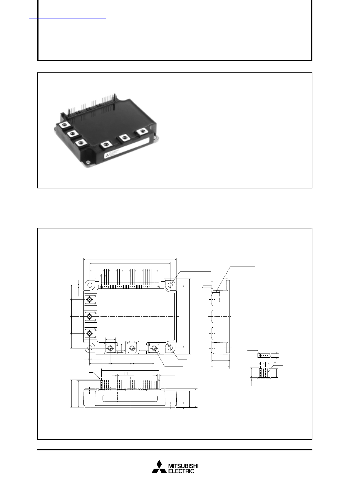
PACKAGE OUTLINES Dimensions in mm
110
17
2020
17.5
32.6
±0.5
2
31.6
2-2.54 2-2.54 6-2.542-2.54
17.02
3.22
BPN
WVU
0.5
±0.3
24.5
A
95
10.16 10.16 10.16
12
10
16- 0.64
LABEL
67.4
±1
±0.5
4-φ5.5
MOUNTING HOLES
1615141312
PBT
6-M5NUTS
2-φ2.54
4-R6
±1
±0.5
89
74
22
19.4
4
10978654321
11
2626
21.2
22
+1.0
–0.5
Screwing depth
Min9.0
Terminal code
1. V
2. U
3. V
4. V
5. V
6. V
7. V
8. W
9. V
10. V
φ2.54
3.22
11.61.6
UPC
P
UP1
VPC
P
VP1
WPC
P
WP1
NC
2-2.54
A : DETAIL
11. V
12. B
13. U
14. V
15. W
16. F
N1
r
N
N
N
O
4.5
0.64
10.6
Sep. 2001
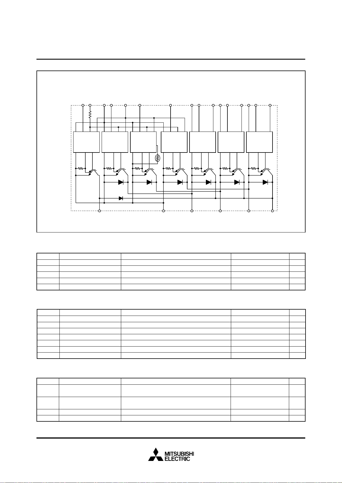
INTERNAL FUNCTIONS BLOCK DIAGRAM
MITSUBISHI <INTELLIGENT POWER MODULES>
PM100RSE060
FLAT-BASE TYPE
INSULATED PACKAGE
Rfo=1.5kΩ
Br Fo
Gnd In Fo Vcc
Gnd
Si Out
V
Rfo
WNV
NC
Gnd In Fo Vcc
Gnd
Si Out
N1
V
Gnd In Fo Vcc
Gnd
N
Si Out
U
Gnd In Fo Vcc
Gnd
Th
N
Si Out
WPV
V
WPC
Gnd In Vcc
Gnd
Si Out
WP1
V
VPC
Gnd In Vcc
Gnd
VPV
VP1
V
UPC
Gnd In Vcc
Si Out
Gnd
UPV
Si Out
UP1
BNWVPU
MAXIMUM RATINGS (Tj = 25°C, unless otherwise noted)
INVERTER PART
Symbol Parameter Condition Ratings Unit
VCES
±IC
±ICP
PC
Tj
Collector-Emitter Voltage
Collector Current
Collector Current (Peak)
Collector Dissipation
Junction Temperature
D = 15V, VCIN = 15V
V
C = 25°C
T
T
C = 25°C
C = 25°C
T
600
100
200
328
–20 ~ +150
V
A
A
W
°C
BRAKE PART
Symbol Parameter Condition Ratings Unit
VCES
IC
ICP
PC
VR(DC)
IF
Tj
Collector-Emitter Voltage
Collector Current
Collector Current (Peak)
Collector Dissipation
FWDi Rated DC Reverse Voltage
FWDi Forward Current
Junction Temperature
V
D = 15V, VCIN = 15V
C = 25°C
T
T
C = 25°C
C = 25°C
T
T
C = 25°C
C = 25°C
T
600
30
60
176
600
30
–20 ~ +150
CONTROL PART
Symbol Parameter Condition Ratings Unit
VD
VCIN
FO
V
IFO
Supply Voltage
Input Voltage
Fault Output Supply Voltage
Fault Output Current
Applied between : V
Applied between : UP-VUPC, VP-VVPC
Applied between : FO-VNC
Sink current at FO terminal
UP1-VUPC
VVP1-VVPC, VWP1-VWPC, VN1-VNC
WP-VWPC, UN • VN • WN • Br-VNC
20
20
20
20
Sep. 2001
V
A
A
W
V
A
°C
V
V
V
mA
 Loading...