

Mitsubishi PM100CVA060 Datasheet
MITSUBISHI INTELLIGENT POWER MODULES
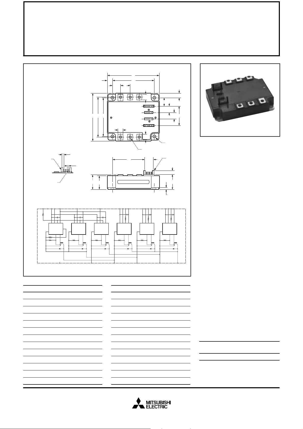
PM100CVA060
FLAT-BASE TYPE
INSULATED PACKAGE
TERMINAL CODE
1. W
FO
11. U
2. V
3. W
4. V
5. V
6. V
7. V
8. V
9. U
10. V
WPC
P
WP1
FO
VPC
P
VP1
FO
UPC
CCφ
P
12. V
UP1
13. Br
14. F
O
15. VNC
16. VN1
17. UN
18. VN
19. WN
B K E
AA - TYP.
(4 PLACES)
Z - TYP.
BB SQ PIN - TYP.
(19 PLACES)
C
DETAIL A
VNC
VN1
WN
Rf
F
O
O
RfO
NC
GND
IN
GND
TH
= 1.5k OHM
Si
FO
TEMP
VCC
OUT
GND
GND
VN
FO
VCC
IN
OUT
Si
NNC
Outline Drawing and Circuit Diagram
Dimensions Inches Millimeters
A 4.33 110.0
B 3.50 89.0
C 0.87 +0.04/-0.02 22.0 +1.0/-0.5
D 3.74±0.010 95.0±0.25
E 2.91±0.010 74.0±0.25
F 0.16 4.0
G 0.87 22.0
H 0.42 10.6
J 0.79 20.0
K 2.99±0.02 76.0±0.5
L 0.39 10.0
M 0.49 12.5
N 0.67 17.0
GND
GND
A
DP
J
N
TYP.
NPB
L - TYP.
UVW
M
1234
5678
9101112
1314 1516
17 1819
M
R
S NUTS (6 TYP.)
XW
Y
VWPC
VWP1
WFO
UN
FO
VCC
IN
OUT
Si
WP
FO
GND
IN
OUT
GND
Si
WVUP
VVPC
VFO
VP
FO
GND
VCC
GND
IN
OUT
Si
VUPC
VVP1
GND
VCC
GND
Dimensions Inches Millimeters
P 0.30 7.5
R 0.65 16.5
S M5 Metric M5
T 0.22 Dia. Dia. 5.5
U 0.56±0.010 14.1±0.25
V 1.72±0.012 43.57±0.3
W 0.57±0.012 14.6±0.3
X 2.90 73.7
Y 0.78 19.7
Z 0.10±0.010 2.54±0.25
AA 1.37±0.010 3.49±0.25
BB 0.02 SQ 0.64 SQ
CC 0.12 +0.04/-0.02 3.0 +1.0/-0.5
U
V
U
T (4 TYP.)
SEE
DETAIL A
H
G
F
VUP1
UFO
UP
FO
VCC
IN
OUT
Si
P
Description:
Mitsubishi Intelligent Power Modules are isolated base modules designed for power switching applications operating at frequencies to
20kHz. Built-in control circuits provide optimum gate drive and protection for the IGBT and free-wheel
diode power devices.
Features:
u Complete Output Power
Circuit
u Gate Drive Circuit
u Protection Logic
– Short Circuit
– Over Temperature
– Under Voltage
Applications:
u Inverters
u UPS
u Motion/Servo Control
u Power Supplies
Ordering Information:
Example: Select the complete
part number from the table below
-i.e. PM100CVA060 is a 600V,
100 Ampere Intelligent Power Module.
Type Current Rating V
Amperes Volts (x 10)
PM 100 60
CES
Sep.1998

MITSUBISHI INTELLIGENT POWER MODULES
PM100CVA060
FLAT-BASE TYPE
INSULATED PACKAGE
Absolute Maximum Ratings, Tj = 25°C unless otherwise specified
Ratings Symbol PM100CVA060 Units
Power Device Junction Temperature T
Storage Temperature T
Case Operating Temperature T
Mounting Torque, M5 Mounting Screws — 2.5~3.5 N · m
Mounting Torque, M5 Main Terminal Screws — 2.5~3.5 N · m
Module Weight (Typical) — 560 Grams
Supply Voltage, Surge (Applied between P - N, Surge Value) V
Supply Voltage Protected by SC (VD = 13.5 ~16.5V, Inverter Part, Tj = 125°C Start) V
Isolation Voltage (Main Terminal to Baseplate, AC 1 min.) V
j
stg
C
CC(surge)
CC(prot.)
iso
Control Sector
Supply Voltage (Applied between V
Input Voltage (Applied between UP-V
Fault Output Supply Voltage (Applied between FO-VNC, *FO-V
Fault Output Current (Sink Current at UFO, VFO, WFO and FO Terminal) I
UP1-VUPC
UPC
, VP-V
, V
VP1-VVPC
VPC
, WP-V
, V
WP1-VWPC
, UN · VN · WN-VNC)V
WPC
*PC
, VN1-VNC)V
)VFO20 Volts
D
CIN
FO
-20 to 150 °C
-40 to 125 °C
-20 to 100 °C
500 Volts
400 Volts
2500 Vrms
20 Volts
20 Volts
20 mA
IGBT Inverter
Collector-Emitter Voltage (VD = 15V, V
Collector Current, (TC = 25°C) I
Peak Collector Current, (TC = 25°C) I
Collector Dissipation (TC = 25°C) P
= 15V) V
CIN
CES
C
CP
C
600 Volts
100 Amperes
200 Amperes
338 Watts
Sep.1998
 Loading...