

MITSUBISHI PM100CSE120 Technical data
查询PM100CSE120_05供应商
MITSUBISHI <INTELLIGENT POWER MODULES>
MITSUBISHI <INTELLIGENT POWER MODULES>
PM100CSE120
PM100CSE120
FEATURE
a) Adopting new 4th generation planar IGBT chip, which per-
formance is improved by 1µm fine rule process.
b) Using new Diode which is designed to get soft reverse
recovery characteristics.
•3φ 100A, 1200V Current-sense IGBT for 15kHz switching
• Monolithic gate drive & protection logic
• Detection, protection & status indication circuits for overcurrent, short-circuit, over-temperature & under-voltage
• Acoustic noise-less 18.5/22kW class inverter application
• UL Recognized Yellow Card No.E80276(N)
APPLICATION
General purpose inverter, servo drives and other motor controls
PM100CSE120
FLAT-BASE TYPE
FLAT-BASE TYPE
INSULATED PACKAGE
INSULATED PACKAGE
File No.E80271
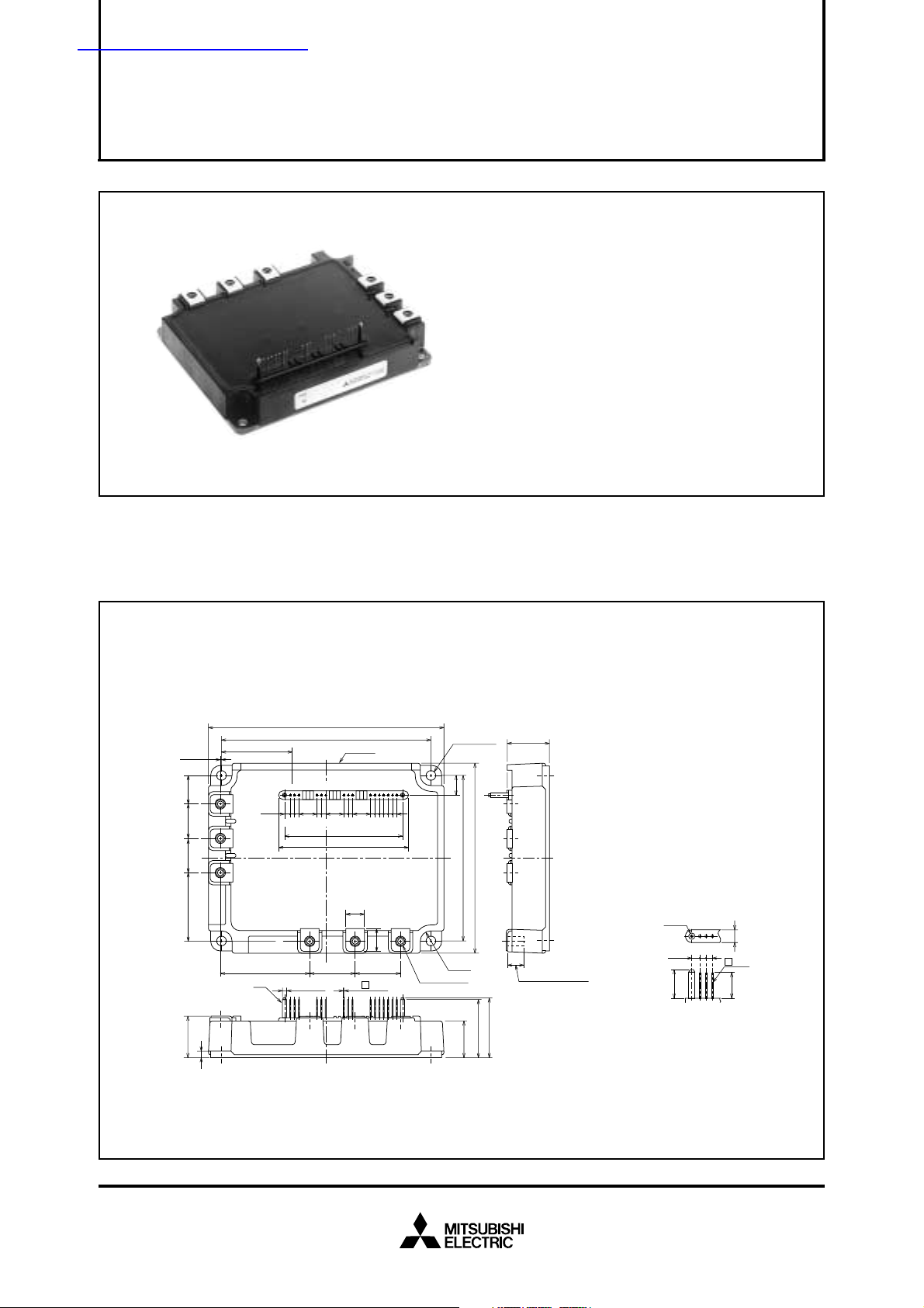
PACKAGE OUTLINES Dimensions in mm
135
±1
120.5
±0.5
LABEL
123 456 789 10111213141516
10.16 10.16 10.16
2-2.54 6-2.54
67.4
74.4
10.5
U
VW
13
26
26
2-φ2.54
16- 0.64
P N B PPS
39.7
3.22
2-2.54 2-2.54
51.5
A
0.5
±0.3
16.5
202039.5
+1.0
24.1 –0.5
4
MOUNTING
HOLES
11
4-R6
6-M5 NUTS
4- φ5.5
95.5 ±0.5
21.3
110 ±1
33.7
34.7
24.1
Screwing depth
Min9.0
Terminal code
1. VUPC
2. UP
3. VUP1
4. VVPC
5. VP
6. VVP1
7. VWPC
8. WP
9. VWP1
10. VNC
φ2.54
2-2.54
3.22
11.6
A : DETAIL
11. VN1
12. NC
13. U
14. VN
15. WN
16. FO
5
0.64
10.6
N
Jul. 2005
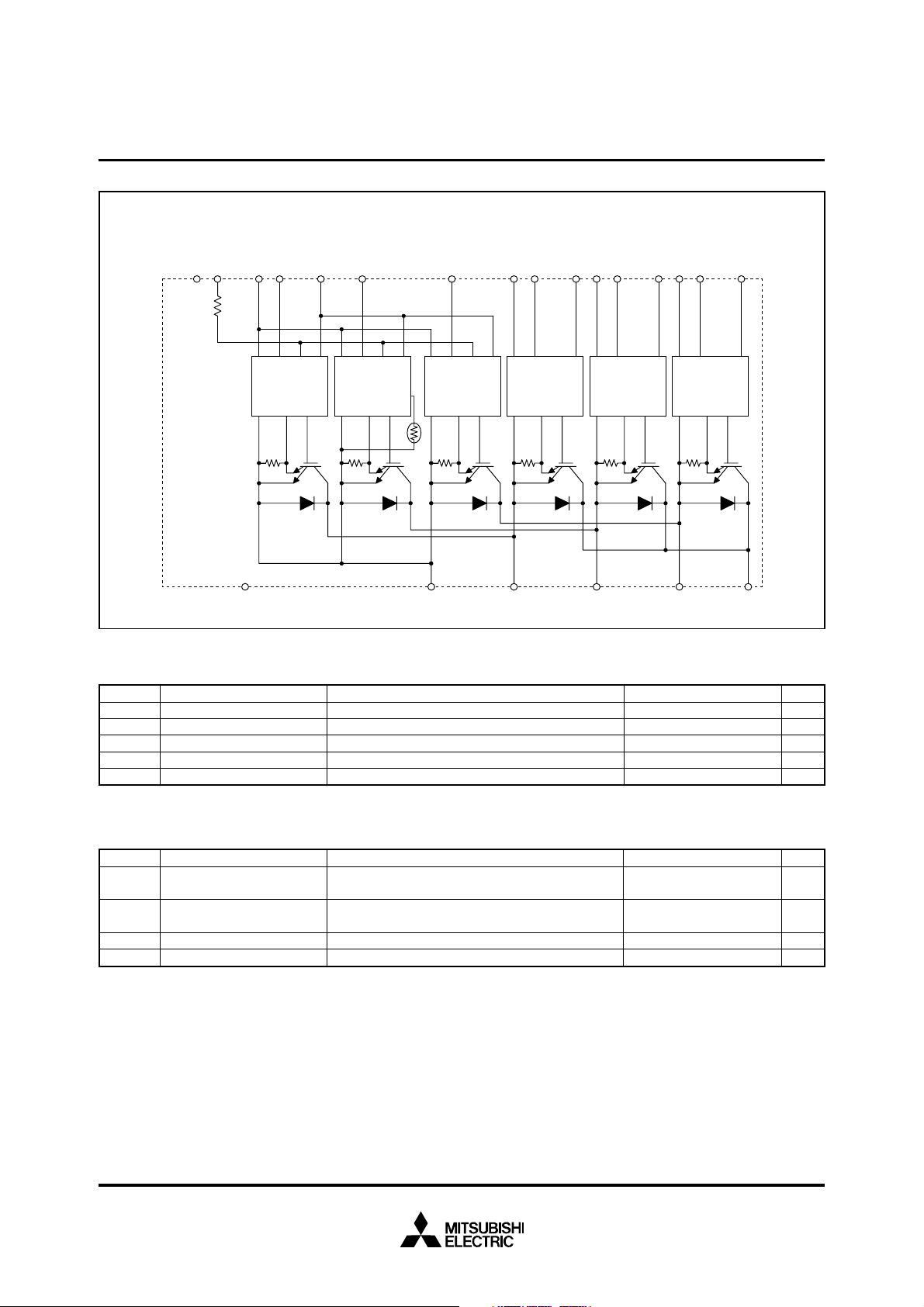
INTERNAL FUNCTIONS BLOCK DIAGRAM
MITSUBISHI <INTELLIGENT POWER MODULES>
PM100CSE120
FLAT-BASE TYPE
INSULATED PACKAGE
Rfo=1.5kΩ
NC Fo
V
Rfo
WNV
NC
Gnd In Fo Vcc
Gnd
Si Out
N1
Gnd In Fo
Gnd
V
N
Vcc
Gnd In Fo Vcc
TEMP
Si Out
Gnd
Th
U
N
Si Out
WPV
V
WPC
Gnd In Vcc
Gnd
Si Out
WP1
V
VPC
Gnd In Vcc
Gnd
VPV
VP1
V
UPC
Gnd In Vcc
Si Out
Gnd
U
P
Si Out
V
UP1
NC N W V PU
MAXIMUM RATINGS (Tj = 25°C, unless otherwise noted)
INVERTER PART
Symbol Parameter Condition Ratings Unit
VCES
±IC
±ICP
PC
Tj
Collector-Emitter Voltage
Collector Current
Collector Current (Peak)
Collector Dissipation
Junction Temperature
V
D = 15V, VCIN = 15V
T
C = 25°C
T
C = 25°C
T
C = 25°C
1200
100
200
595
–20 ~ +150
V
A
A
W
°C
CONTROL PART
Symbol
VD
VCIN
VFO
IFO
Supply Voltage
Input Voltage
Fault Output Supply Voltage
Fault Output Current
Parameter Condition Ratings Unit
Applied between : V
Applied between : UP-VUPC, VP-VVPC
Applied between : FO-VNC
Sink current at FO terminal
UP1-VUPC
VVP1-VVPC, VWP1-VWPC, VN1-VNC
WP-VWPC, UN • VN • WN-VNC
20
20
20
20
V
V
V
mA
Jul. 2005
TOTAL SYSTEM
Symbol
V
CC(PROT)
V
CC(surge)
TC
Tstg
Viso
Supply Voltage Protected by
OC & SC
Supply Voltage (Surge)
Module Case Operating
Temperature
Storage Temperature
Isolation Voltage
Parameter
V
D = 13.5 ~ 16.5V, Inverter Part,
j = 125°C Start
T
Applied between : P-N, Surge value or without switching
(Note-1)
60Hz, Sinusoidal, Charged part to Base, AC 1 min.
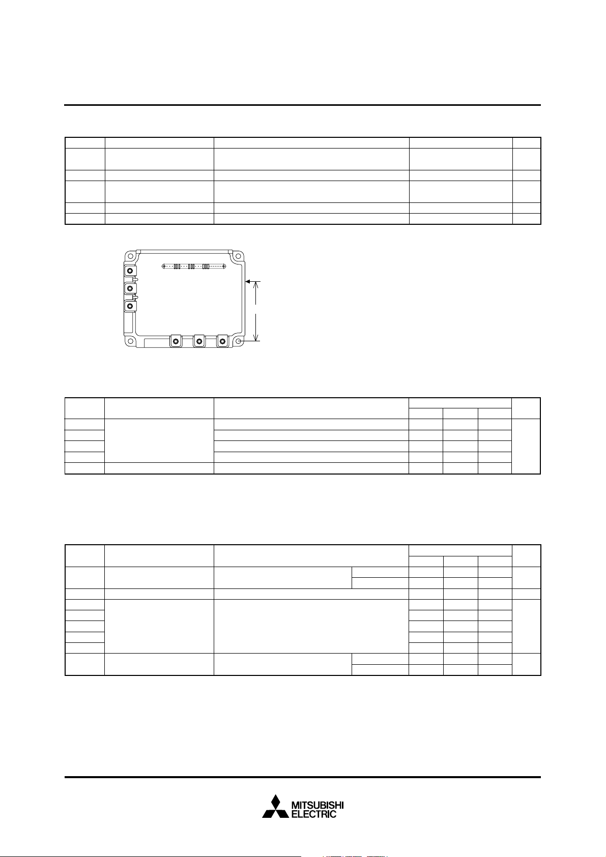
(Note-1) TC measurement point is as shown below. (Base plate depth 3mm)
Condition
MITSUBISHI <INTELLIGENT POWER MODULES>
PM100CSE120
FLAT-BASE TYPE
INSULATED PACKAGE
Ratings
800
1000
–20 ~ +100
–40 ~ +125
2500
Unit
°C
°C
V
V
V
rms
PNB
Tc
63mm
U
VW
THERMAL RESISTANCES
Symbol Parameter
Rth(j-c)Q
Rth(j-c)F
Rth(j-c’)Q
Junction to case Thermal
Resistances
Rth(j-c’)F
Rth(c-f)
(Note-2) T
Contact Thermal Resistance
C measurement point is just under the chips.
If you use this value, R
Inverter IGBT part (per 1 element), (Note-1)
Inverter FWDi part (per 1 element), (Note-1)
Inverter IGBT part (per 1 element), (Note-2)
Inverter FWDi part (per 1 element), (Note-2)
Case to fin, Thermal grease applied (per 1 module)
th(f-a) should be measured just under the chips.
Test Condition
ELECTRICAL CHARACTERISTICS (Tj = 25°C, unless otherwise noted)
INVERTER PART
CE(sat)
V
VEC
ton
trr
tc(on)
toff
tc(off)
ICES
ParameterSymbol
Collector-Emitter
Saturation Voltage
FWDi Forward Voltage
Switching Time
Collector-Emitter
Cutoff Current
D = 15V, IC = 100A
V
V
CIN = 0V, Pulsed (Fig. 1)
–I
C = 100A, VD = 15V, VCIN = 15V (Fig. 2)
D = 15V, VCIN = 15V↔0V
V
V
CC = 600V, IC = 100A
T
j = 125°C
Inductive Load (upper and lower arm) (Fig. 3)
VCE = V
CES
, V
CIN
= 15V
Test Condition
(Fig. 4)
T
j = 25°C
T
j = 125°C
T
j = 25°C
T
j = 125°C
Limits
Min. Typ. Max.
—
—
—
—
—
—
—
—
—
—
0.21
0.35
0.13
0.21
0.018
Limits
Min. Typ. Max.
—
—
—
0.5
—
—
—
—
—
—
2.4
2.1
2.5
1.0
0.15
0.4
2.5
0.7
—
—
3.2
2.8
3.5
2.5
0.3
1.0
3.5
1.2
10
Unit
°C/W
Unit
V
V
µs
1
mA
Jul. 2005
 Loading...