

Mitsubishi PLY-E7203, PLY-E7200, PLY-E7100, PLY-E7194, PLY-E7191 Instruction Manual
AUTOMAT
I C
POCKTT \l/E
LT I NG
MACH
I NE
PLY-E72OO
PLY_E71OO
(rXS
TRTJCTIoN
SERIES
SERIES
MANU,qr
))
No.
303036
We wish
to express
you
AUTOMATIC POCKET
read this instruction
this machine
will be
manual
geat
sincere thanls
our
WELTING
carefully
potential factor
your
for
MACHINE.
before starting
production.
your
in
CONTENTS
purchase of
should be thanktul
We
operation and
the
our
MITSUBISFtr
you
would
if
hope that
we do
1.
2.
3.
4.
CONSTRUCTION
SPECIFICATION
PREPARATION
OPERATIONPANEL
5. OPERATION
6.
7
OPERATION
SELECTION
"
7-1 SET
7-2 SET
ADruSTMENT
7-3
I.'P FOR
I.'P IN DIP
8. COTJNTER
9.
IO.
11.
12.
13.
T4.
15.
16.
ADruSTMENT
PROCESS
LIST OF OPERATION
ADruSTMENT
INSTRUCTION
EXCHANGE
CONNECTION
MARKING
LAMP
INDICATION
IGI)TNDICATION
I6.2)INDICATION
16-3)CONFIRMATION
AND INSTRUCTION
BEF'ORE
AND
STARTING
MEMORY FOR EACH
BEFORE
MACHINE
OPERATION
SWITCH
OF TIMER
OF TAB KNIFE
OF DOUBLE AND
SINGLE
FOR MACHINE HEAD
OF GAUGE PARTS
TO AIR
FOR TROUBLE
TROUBLE POINTS
FOR
FOR OPERATION POINTS
OF SWITCH CONDMON
OPERATION
FUNCTION
WELT
(SEr
OF THE MACHINE
UP)
(l)
1
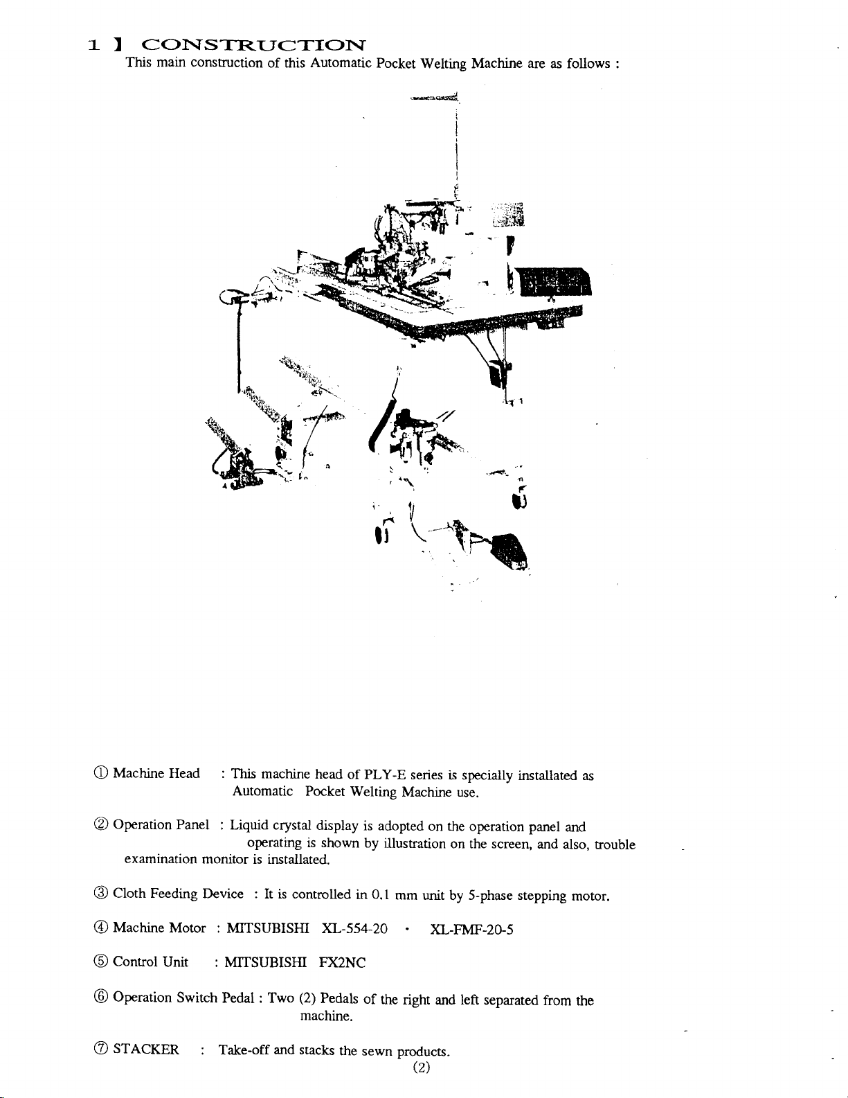
COhISTR.IJCTIOI\I
)
main construction
This
of this Automatic
Pocket
Welting Machine
are
as follows :
Machine
O
operation
@
examination
Head :
Panel
monitor
This machine
Automatic
: Liquid crysral
operating
is installated.
Pocket
is shown
head
of
Welting
display
6
(
lt
\
PLY-E
is adopted
by
series
Machine use.
illustration
-*g,
\h(h
is specially
on rhe
operarion
on the screen,
(
Ufilw
instaliated as
panel
and
and
also, trouble
clottr Feeding
@
Machine
@
Control
@
operation
@
SfeCfgn
@
Motor
Unit
swirch
Device :
: MITSUBISHI
: MITSUBISHI FX2NC
Pedal : Two
: Take-off
Ir is conrrolled
){J--554-20
(2)
Pedals
machine.
and stacks
0.1
in
mm
of
the
rhe
sewn products.
unir
right
Q)
S-phase stepping
by
)CL-FMF-2G5
and left separared
from
motor.
the
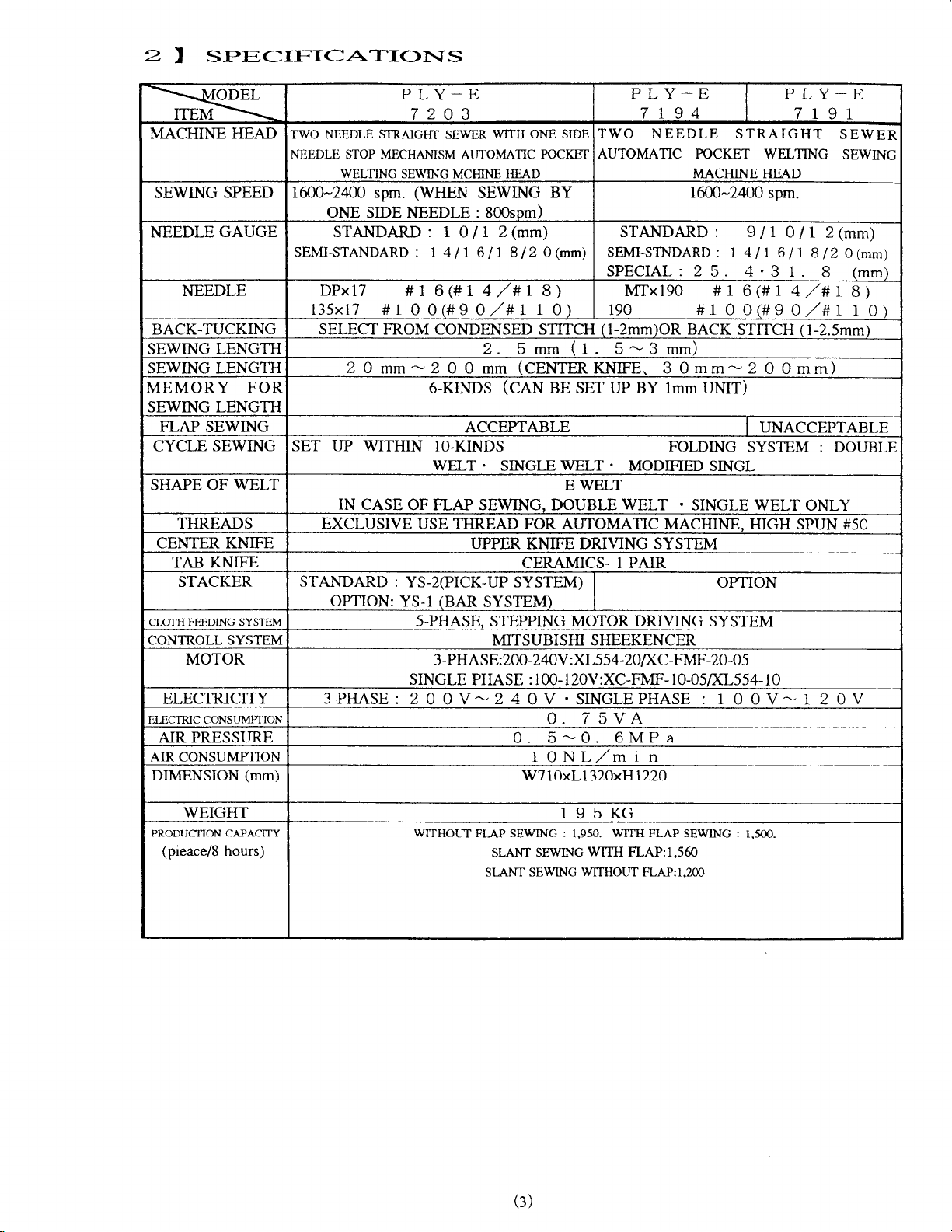
2
seeCIFI<]ATIohTS
I
PLY-E
R
MACHINE HEAD TWO NEEDLE
NEEDLE STOP MECHAMSM
WELTING
SEWING
NEEDLE
SPEED rffi-z4m spm.
ONE
GAUGE STANDARD: 1
SEMI-STANDARD : 1 4lr
NEEDLE
DPx17
l35xr7 #l
7203
STRAIGIIT
SEWING
SEWER
AUTOMATIC
MCHINE
(WHEN
SIDE
NEEDLE : 800som)
0/1
#1 6(#14,/#tB)
0 0(#9 0
WTIH
ONE
POCKET
I{EAD
SEWING
2(mm)
617 812
/#t
O
1o)
STDE
BY
(mm)
BACK.TUCKING SELECT mOM CONDENSED STITCH
SEWING LENGTH 2.
SEWING LENGTH
MEMORY
FOR
20mm-2O
6-KINDS
0mm
5mm
(CENTERKNIFE.
(CAN
(1
BE SET IJP BY lmm UMT)
SEWING LENGTH
FLAP SEWING
CYCLE
SHAPE OF
SEWING SET UP WITHIN
WELT
THREADS
CENTER KNIFE
TAB KNIFE
STACKER
CI.OTTI
FEEDING
CONTROLL SYSTEM
MOTOR
ELEC1RICITY
EI-ECTRIC
AIR PRESSIIRE
AIR CONSUMPTION
DIMENSION
SYSI-EM
CONST'IVIPI]ON
(mm)
IN CASE
EXCLUSTVE
STANDARD
OPTION:
3-PHASE
OF FLAP SEWING. DOUBLE
:
YS-2(PICK-UP SYSTEM)
YS-l
s-PHASE. STEPPTNG MOTOR DRIVING SYSTEM
SINGLE
: 2
ACCEPTABLE UNACCEPTABLE
IO.KINDS FOLDING
WELT
USE
.
SINGLE
WELT
WELT
E
TIIREAD FOR AI.ITOMATTC MACHINE. HIGH SPUN #50
UPPER
KNIFE DRIVING
CERAMICS- I PAIR
(BAR
SYSTEM)
MITSUBISHI SHEEKENCER
3-PHA SE: 200-240V : XL5
PHASE : 1 00- 1 20V : XC-FMF- 1 0-05/XL5 54- 1 0
O OV-24 0V . SINGLEPHASE
0. 75VA
0. 5-0.
1ONL/min
W7
10xl-l 32OxHl22O
PLY-E
7194
TWO NEEDLE STRAIGHT
AUTOMATIC
POCKET WELTING
MACHINE HEAD
1600-2400
PLY_E
7r91
spm.
STANDARD: 9/1O11
SEMI-STNDARD : I 4 | t
SPECIAL : 2
5.
4
6
.
3 1 .
11 8 12
8
MTxl9O #16(#14,/#18)
190 #r00ft90,/#1
(l-2mm)OR
5-3
BACK
mm)
30mm-2
.
MODIFIM SINGL
WELT
.
STITCH
SYSTEM
SINGLE WELT
(l-2.5mm)
00mm)
: DOUBLE
ONLY
SYSTEM
OPTION
54-20lXC-FNf'-20-05
: I
0 0V- 1 2 0
6MPa
SEWER
SEWING
2(mm)
O(mm)
(mm)
l0)
V
WEIGHT
PRODI'CTION CAPACTTY
(pieace/8
hours)
WITHOLIT
FLAP SEWING
SEWING
SLANT
SI,A.NT SEWING
(3)
195KG
:
WTIH
1,950.
WTIH
WTIHOLIT
FLAP:1,560
FLAP SEWNG
FLAP:1.200
: 1,5OO.
3I
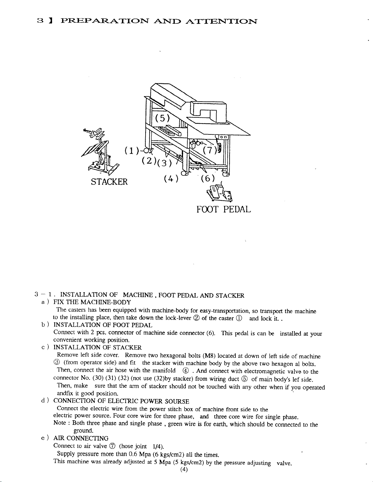
PREPARATIOI\T
STACKER
(1)
(2)13y
AI\ID
AT:TENT:rIOI\T
3-1
a)
b)
c,l
d)
e)
.
INSTALLATION
FIX
TT{E
MACHINE-BODY
The
casters has been
to
the
installing
INSTALLATION
Connect
convenient
INSTALLATION
Remove
@
Then,
connector
Then,
andfix
CONNECTION
Connect
electric
Note
AIR
Connect
Supply
This
with
2
working
left
side cover.
(from
operator
connect
No.
make sure
good position.
it
the electric
power
: Both
three phase
$ound.
CONNECTING
to air valve
pressure
machine was already adjusted
OF
place,
OF
pcs.
connector
position.
OF
side) and
the ah
(30)
(31) (32)
that the
OF
ELECTRIC
source.
@
more rhan
equipped
then take
FOOT
STACKER
hose with
wire
Four core wire
MACHINE,
with
down
PEDAL
of
Remove
fit
the stacker
the
(not
arm
of
POWER
from the
single phase
and
joint
those
0.6
Mpa
FOOT
machine-body
the
lock-lever
machine
rwo
use
at
side connector
hexagonal
with
manifold
(32)by
stacker should
power
for
lt4).
(6
5 Mpa
stacker)
SOI.'RSE
stitch
three phase,
green
,
kgs/cm2) all
(5
FOOT PEDAL
PEDAL
kgs/cm2)
(4\
AND STACKER
for easy-transportation,
of the caster
@
(6).
This pedal
(M8)
bolts
machine
. ena connect
@
from wiring
not be
box of
wire
is for
the
located at
body by
touched with
machine front side
and three
earth, which
times.
pressure
by the
so transport
and
lock
O
is can be
down of
the above
with electromagnetic
duct
core wire
of main
@
any
other when
to the
for
should
adjusting
it.
installed
left
side of
rwo
hexagon
body's
single phase.
be
connected
valve.
the
.
if
machine
machine
al bolts.
vaive
lef
you
your
ar
to
the
side.
operated
rhe
to
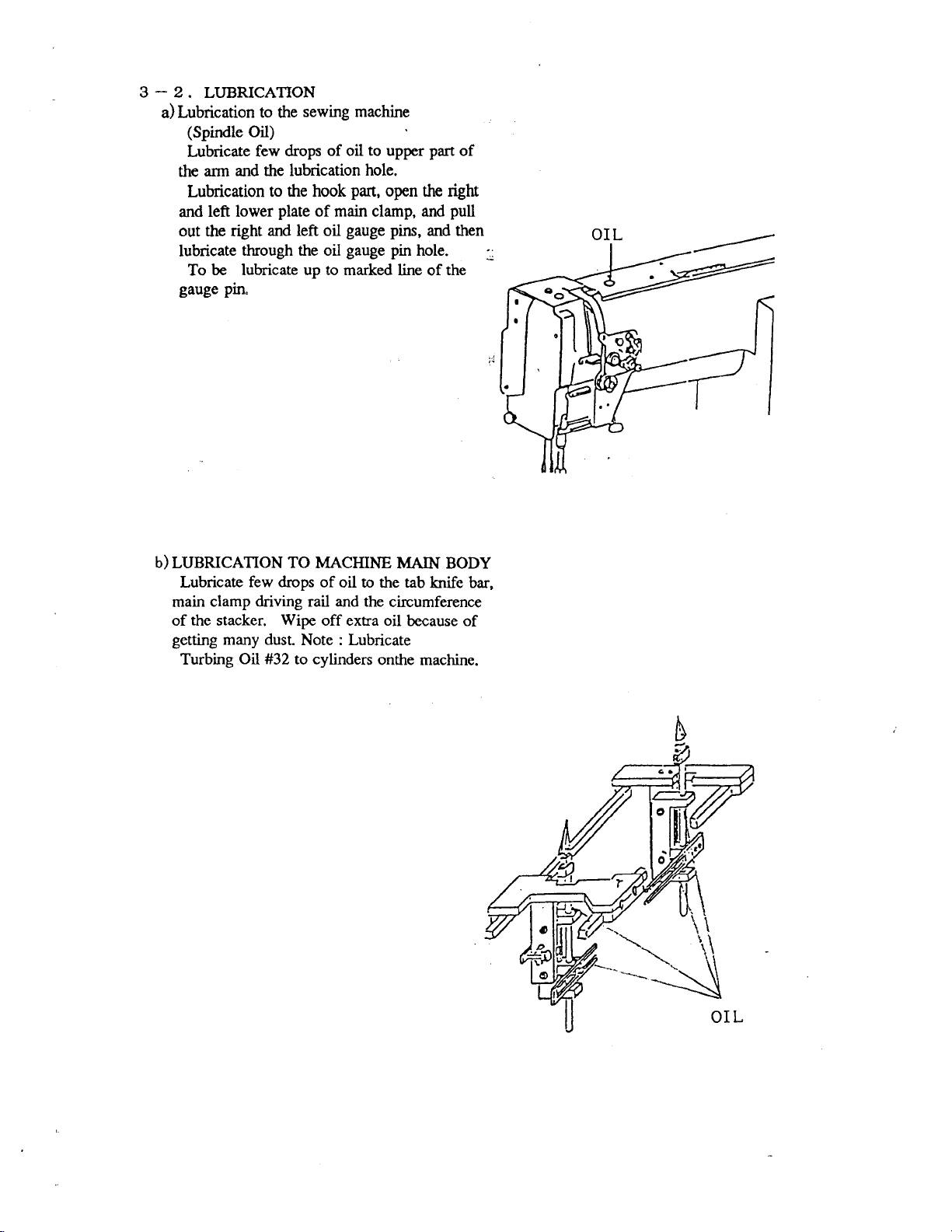
3 _ 2.
LUBRICATION
a)Lubrication
(Spintle
Lubricate
arm
the
Lub,rication
and
out the right
lubricate
To
gauge pin"
sewing machine
to
the
Oil)
of oil to upper part of
drops
few
and the lubrication
the
to
hook
plate
Ieft lower
through the oil
be lubricate up to marked
of main clamp, and
and left oil
hole.
part,
gauge pins,
gauge
open the rigttt
pull
and then
pin
hole.
line of
the
:
b)
LUBRTCATION TO MACHINE
Lubricate
main
the
of
gening
Turbing
few drops
clamp driving rail and the
stacker.
many dust.
Oil #32
of oil to the tab
Wipe
off extra oil
Note : Lubricate
to cylinders
MAIN BODY
knife bar,
circumference
because of
onthe
machine.
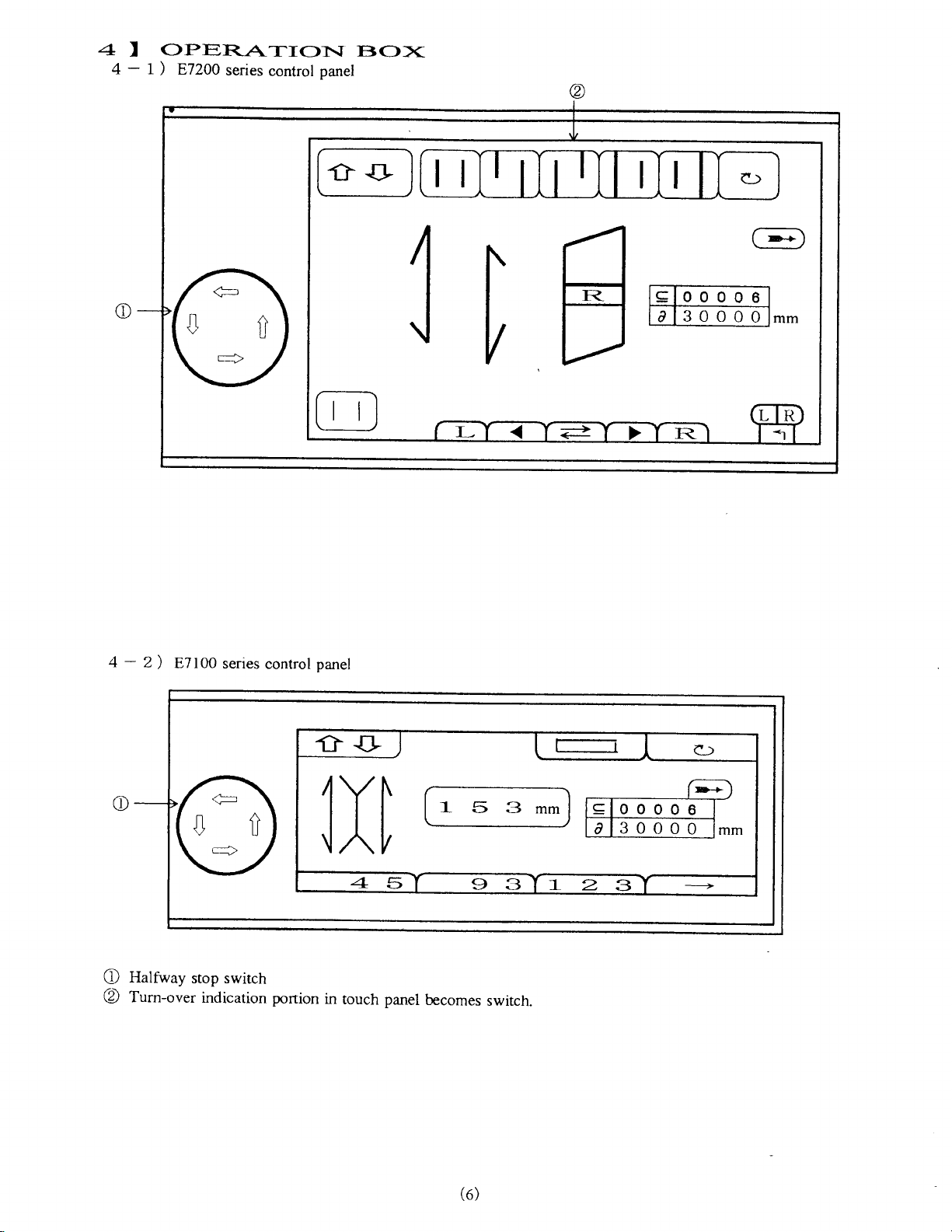
4I
4-
OPER.ATIOhI
|
E7200
)
series
control
ETO><
panel
tl
l;
ll
g
00006
30000
a
c)
-
4
c
Halfway
\t
Turn-over
@
2
87100
)
series
stop switch
indication
control
portion
panel
r'--;=;
]n
in
I
5
touch panel
becomes
switch.
00008
_c
I
30000
3I0
o
I0I
lD-+ I
L-------J
8l
0
0_l.-
F
m
(e)
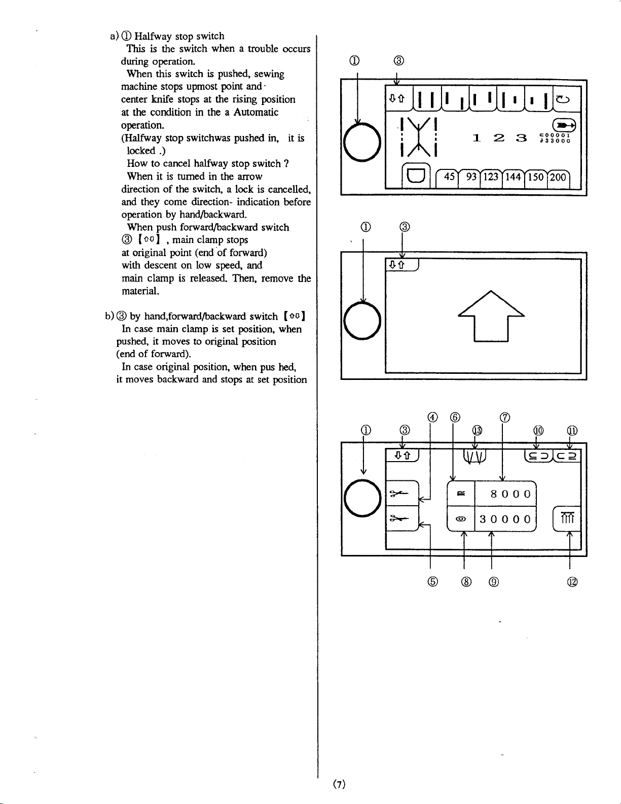
a)
Hafway stop
O
This is the switch
during
machine stops
center knife stops at the
at the condition
operation.
(Halfway
direction
and
operation by hand/backward.
@
at original
with descent on low speed
main clamp is released Then,
material.
b)@
ln
pushed,
(end
ln
it moves
operation.
When this
stop switchwas
locked
How to
When it is tumed
When
.)
cancel
of the
they come direction- indication
push
[ool
by hand,forward/backward
case
main clamp is set
it moves to original
of
forward).
case original position,
backward and stops
switch
when a
pushed,
swirch
main
,
point
is
upmost
in the a Automatic
halfivay stop switch
in the
switch, a lock is cancelled,
forward/backward
clamp
(end
of forward)
trouble
sewing
point
and'
rising position
pushed
arrow
switch
stops
and
remove the
swirch
position,
position
when pus
at
set
occurs
in, it is
?
before
Iool
when
hed,
position
!
I
(z)
F\
\?/
@
/61
5
OPER-A:TTOI\T
I
BEFOR.E
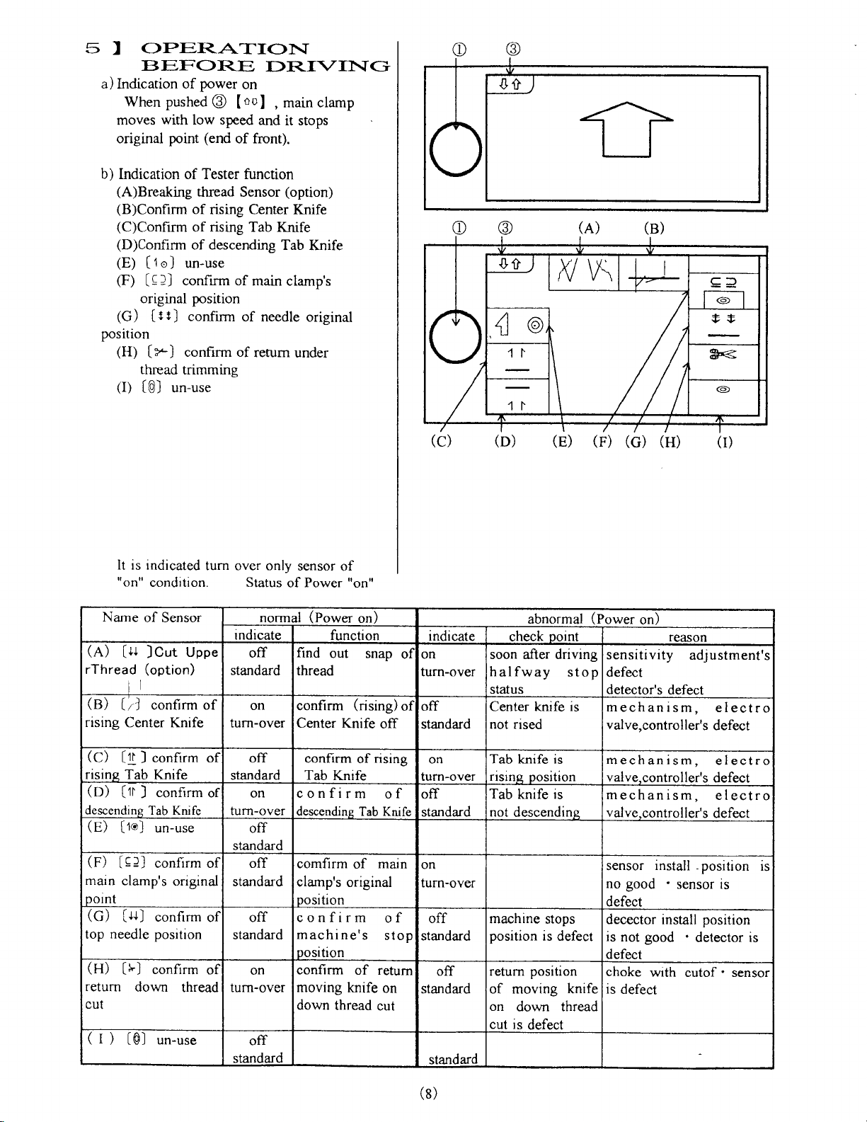
a)
Indication
When pushed
moves
original
b)
Indication of Tester function
(A)Breaking
(B)Confirm
(C)Confirm
(D)Confirm
(E)
[1o]
(F)
tqll
original
(G)
[rtJ
power
of
@
with low speed
(end
point
thread
of
rising Center Knife
rising
of
of descending
un-use
confirm of
position
confirm of needle
position
(H)
thread
O)
[r)
tOl
conhrm of
trimming
un-use
DR.I\
on
,
and
main
it stops
tool
of front).
Sensor
(option)
Tab Knife
Tab
main clamp's
refum
under
T
clamp
Knife
original
TG
It is indicated
turn
"on" condition.
Name
(A)
rThread
(B)
rising
(C)
risinq Tab
(D)
descending
(e)
/-\ r--t
tl.i LeJj conllrm of
main
potnt
(G)
top needle
(H)
return
nr rt
(l)
of Sensor normal
[u Jcut
[r-]
Center Knife
['1f
]
[1] J
[1o]
clamp's
[$]
[tsJ
down
tOl
uppe
(option)
confirm of
confirm of
Knife
confirm
Tab Knitc
un-use
original
confirm
position
confirm
thread
un-use
or
of
of
over only
Status
rndicate
off
standard
on
turn-over
off
standard
on
turn-over
off
standard
off
standard
off
standard
on
turn-over
off
standard
sensor
of
Power
(Power
of
"on"
on)
function
find
out
snap
thread
confirm
Center
confirm
Tab
c o n f ir
descending Tab Knife
comfirm
clamp's
(rising)
Knife
of
Knife
m
of main
original
rising
position
confirm
machine's
oosition
confirm
moving
down
of retum
knife
thread
cut
off
o f
of
stop
on
(c) (D)
indicate
ol
on
turn-over
ol
off
standard
on
turn-over
off
standard
on
turn-oYer
off
standard
off
standard
standard
(E) (F)
abnormal
point
check
soon after driving
halfway
status
Center knife is
not rised
Tab knife
risins
Tab
knife is
not
descendins.
machine
position
return posrtlon
of moving knife
on
down
cut is
5
IOn
oosi
stops
is defect
defect
stop
thread
(c) (H)
(Power
on)
reason
sensitivity
defect
detector's
mechanism,
valve,controller's
mechanism,
valve.controller's
mechanism,
valve,contro
sensor
good
no
defect
install
'
defect
decector install
is
not good
defect
choke
is
with cutof ' sensor
defect
adjustment's
electro
defect
electro
defect
electro
ll
er's defect
position is
sensor
is
position
'
detector is
(8)
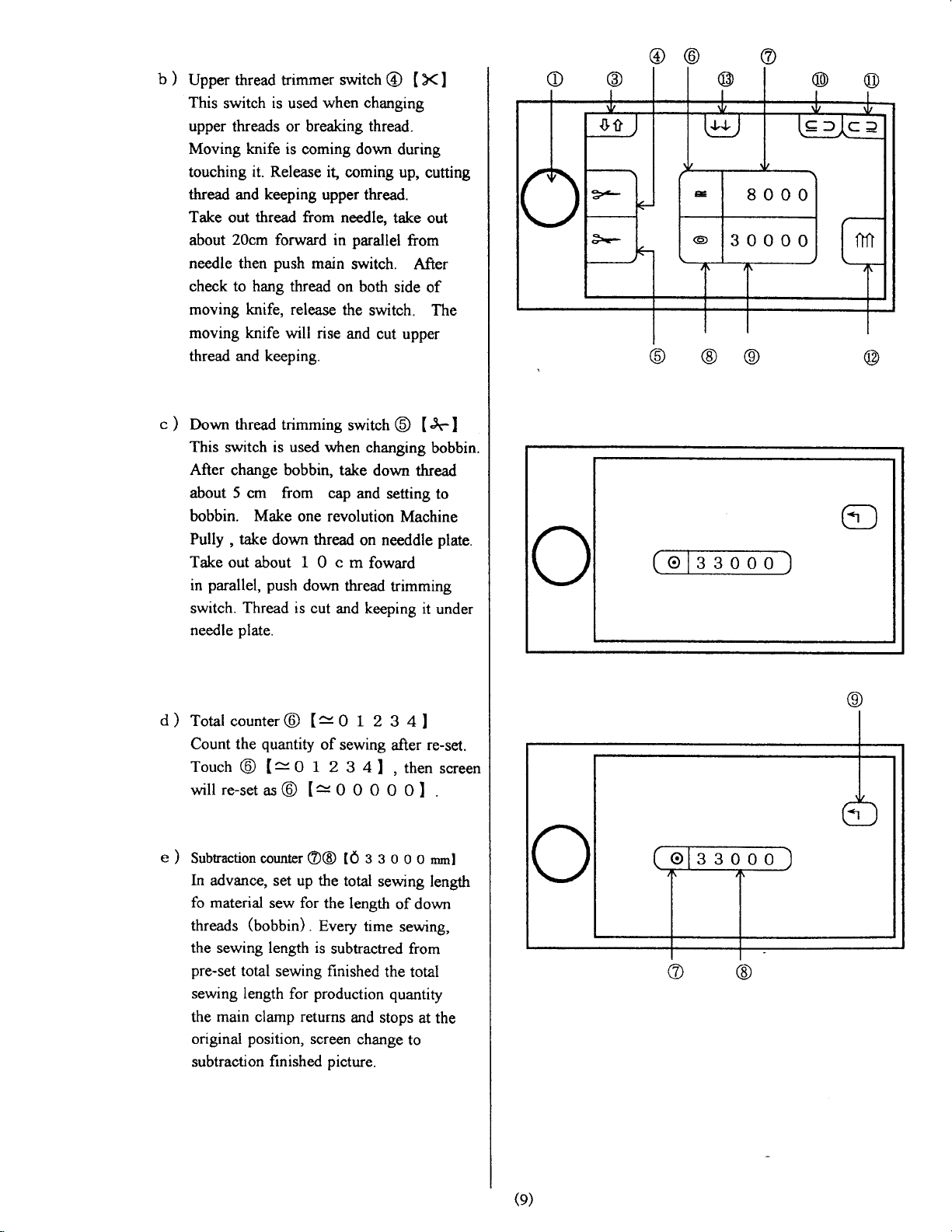
b)
Upper
This
touching
thread
Take
c)
thread trimmer
switch
upper
Moving knife
about
needle then
check to hang thread
moving knife, release
moving knife
thread and keeping.
Down thread trimming
This switch is
After change bobbin, take
about 5 cm from
bobbin.
Pully , take
Take
parallel, push
in
switch"
needle
is
used
threads or breaking
is coming down
it.
Release it,
keeping
and
thread from
out
20cm
forward in
push
will
used when changing
Make
one revolution
down
out about 1 0 c m
Thread
plate.
is cut
switch
when changing
thread.
coming up,
upper thread.
needle,
parallel
main
switch. After
on both
the
switch. The
rise
and
cut upper
switch
down
cap
and setting
thread
on needdle
foward
down
thread
and keeping it
@
t X I
during
cutting
take out
from
side
of
@ tJ.l
thread
Machine
trimming
bobbin.
to
plate.
under
o
@
\q/
A
LS/
@
@
O
d)
Total
counter@
Count the
Touch
will
e)
Subtraction counter
ln
advance, set up
fo material
threads
the sewing length is
pre-set
sewing
the main clamp returns
original
subtraction
quantity
@ [=
re-setas@
sew for
(UoUUln).
total
sewing
length for
position,
finished
O L 2
[=
of
sewing
O I 2
3 4
O O
[=0
O@ tO
production
screen change
3 3 0
the total
the length
Every time
subtractred from
finished
and
picture.
3 4l
after re-set.
then
I,
0 OI
0 o
mml
sewing
stops
length
of down
sewing,
the total
quantity
at the
to
screen
.
(e)
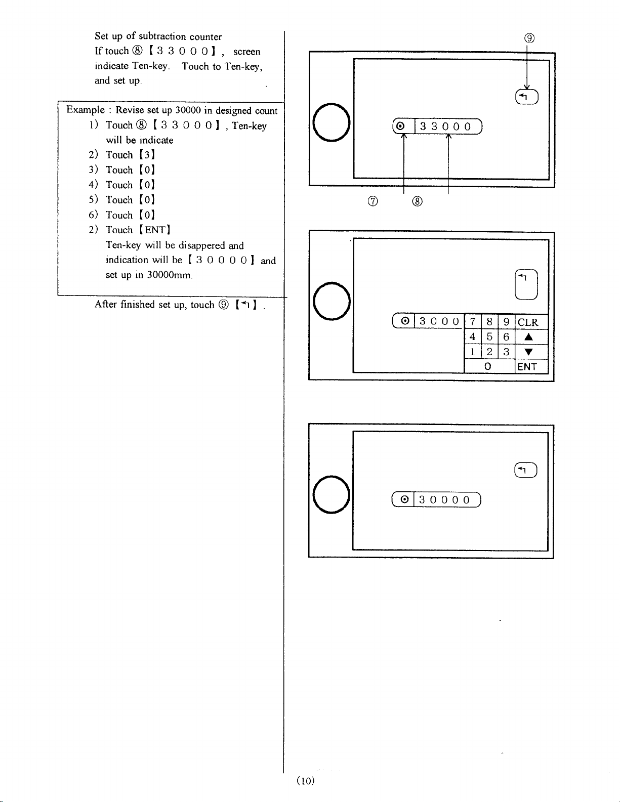
Set up
If
indicate Ten-key.
and
of
touch
set up.
subtraction
g
@ t
3
counter
0
0 0
Touch
screen
I,
to Ten-key,
Example
1) Touch@
z)
:)
+)
s)
6) Touch
2) Touch
After finished
:
Revise set up 30000
g
3 0
I
will
touch
rouch
touch
Touch
Ten-key
indicationwill
set up rn 30000mm.
indicate
be
[31
[01
[ol
lol
[01
lgNrl
will
be disappered
be
set up,
IgOOO0l and
in
0
0
touch
designed
l
.Ten-key
and
@ [1
I
count
o
o
@IersCD
(
ro)
f
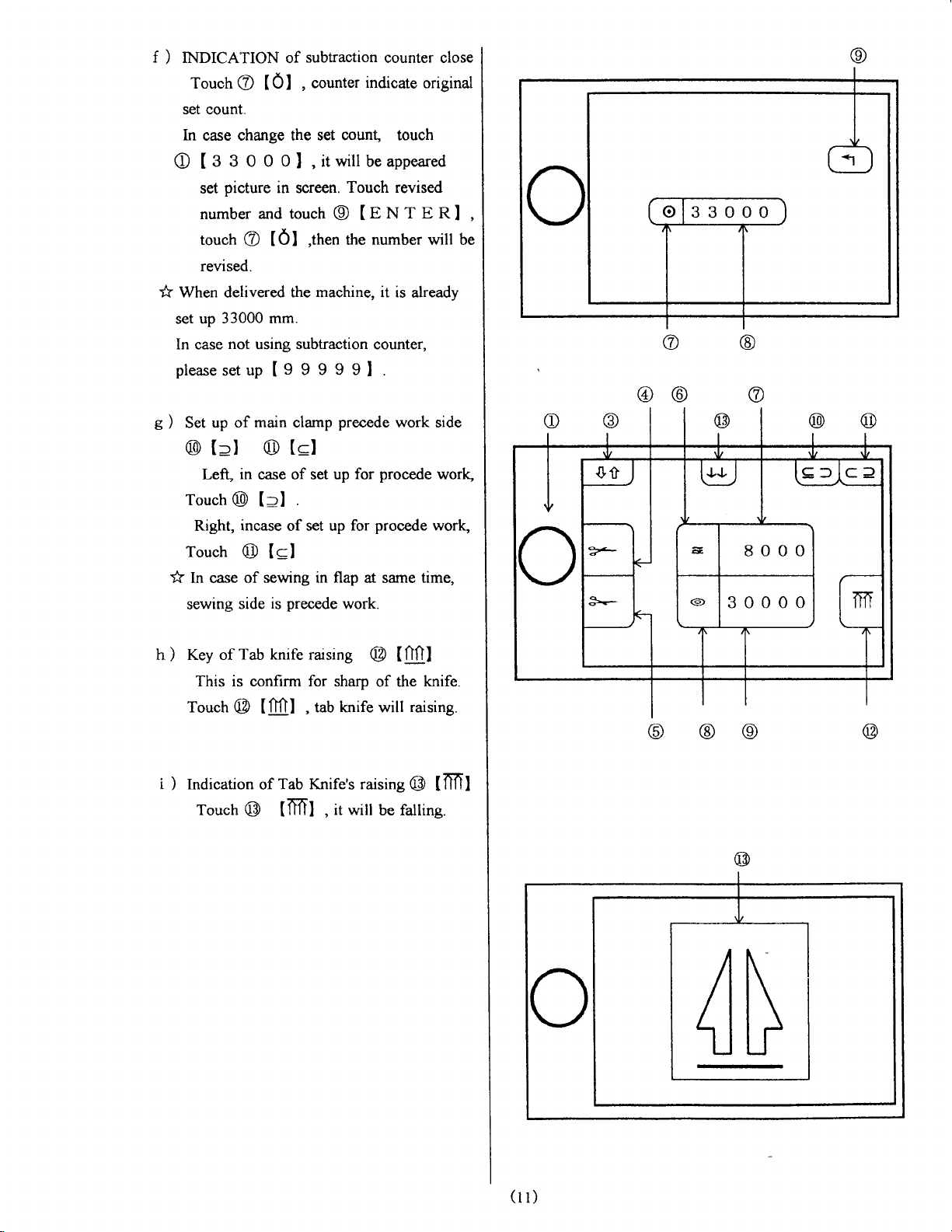
INDICATION
)
Touch@
(01
of
,
subtraction
counter
set count.
ln
O
* When delivered
set up
In case
pleasesetup[999991.
Set
)
e
@ [:l @
Touch
Touch
* [n case of
sewing
change the set
case
g
3 o 0 o
t
picture
set
number
touch
revised.
33000 mm.
not
up of main clamp
in screen.
and touch
@ [0]
the machine, it is
using subtraction counter,
(ql
Left, in
Right,
@ [:l
incase
@ Isl
side
of set up for
case
of set up
sewing in flap
precede
is
count, touch
itwill beappeared
I,
Touch revised
@
the
,ttten
precede
.
for
work.
counter close
indicate
Ie
number
procede
at same time,
original
NT E RL
will be
already
work side
procede
work,
@@
work,
h) Key
of
Tab
knife rarsing
This is confirm for sharp
Touch
i
Indication of
)
Touch
tfifll
@
Tab Knife's raising
@ [nfrl
@
of the
tab knife will
,
it will
,
be falling.
t00t
knife
raising.
@ tml
\0/
fol
.9
@
/ih
\atl
I
4N
(n)
6
6
a
b
OPER.ATIO5I
f
-
f
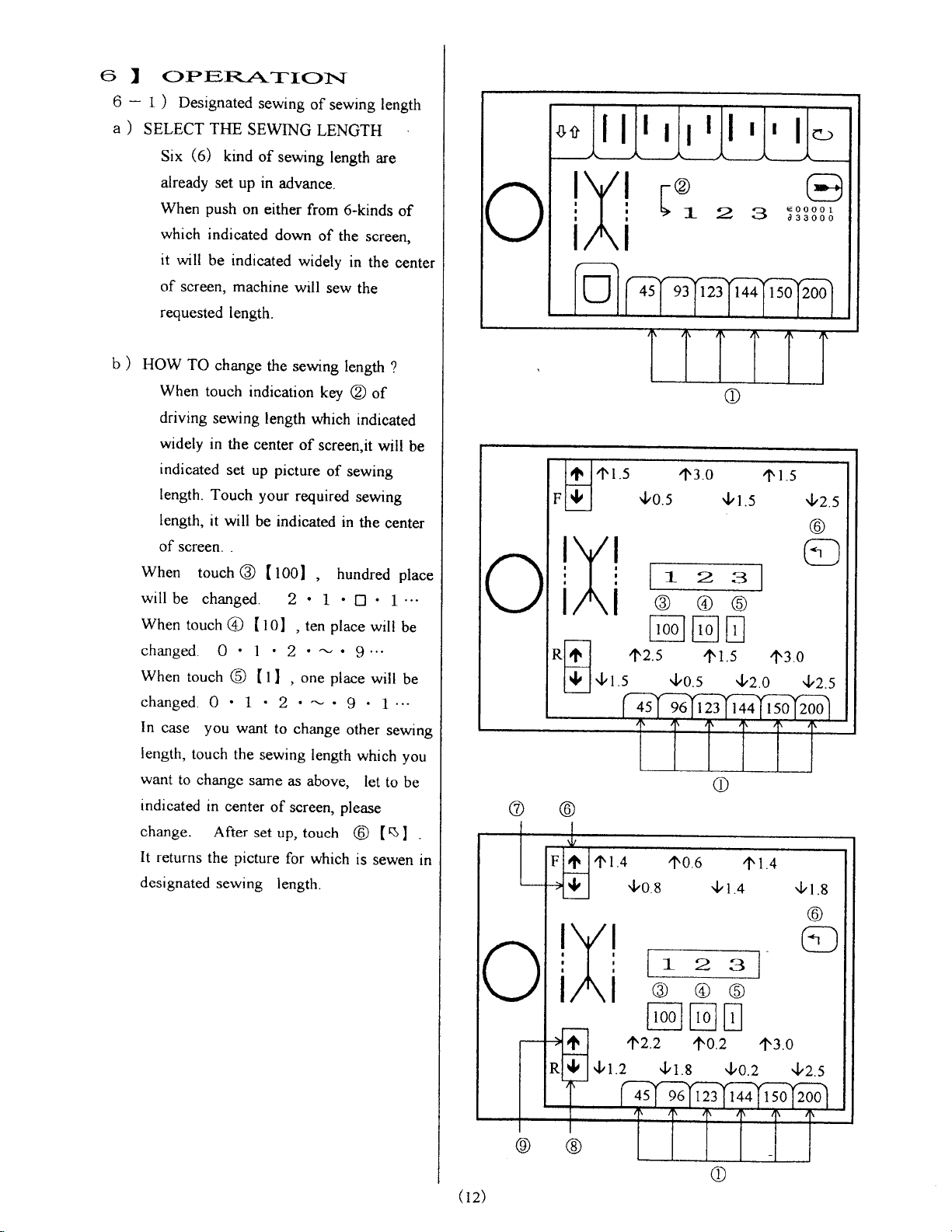
Designated
)
seLgCT
)
Six
already set
When push
which
it
will
of screen, machine
requested
HOW
)
When
driving
wrdely
indicated
length.
length,
of
screen. .
When
will
be changed.
When
changed.
Whentouch@
changed.0
In
case
length,
want
to
indicated
change.
It
returns
designated
sewing
TFm
SEwING
(6)
kind
of
up in
on either
indicated
be indicated
TO
change
touch
sewing
in
set up picture
Touch your
it
will
touch
touch
@ I
0 l.).*.9.'.
you
touch
change
in
center
After
the picture
sewing
down
length.
the sewing
indication
length
the
center
be indicated
toOI
@
[
tOI
ttl
1.2.-.9
want
to
the
sewing
sarne
of screen, please
set up, touch
of
sewing
LENGTH
sewing
advance.
length.
length
are
from
6-kinds
of the
screen,
widely
will
of
required
2,
,
,on"placewill
change
as
for
in
sew
the
length
key
@
which
indicated
screen.it
of
sewing
sewing
in
the
hundred
,
.
L
D
ten place
other
length
which you
above,
which
let
@
is
the
of
will
.
will
sewen
length
of
center
?
be
cenrer
place
1...
be
be
1...
sewing
to be
$
t
I
.
rn
@
I
RI
/F\
a,
Ol.5
ll^2.s
Ot.s
ffi
Ol.4
9oa
,f3.0
Oo.s
a
@
Or.s
2
@@
ujE[qiu
fls 430
.l,o.s
c
,106
{t.+
3
{z.o
41.4
,ttl5
tz.s
@
6]
,lrz.s
.l,t.s
Q2)
,lrt.Z
l-
+2.2
Ot.g
2
lo.Z
3
'13.0
'l'O.Z
@
,lrZ.S
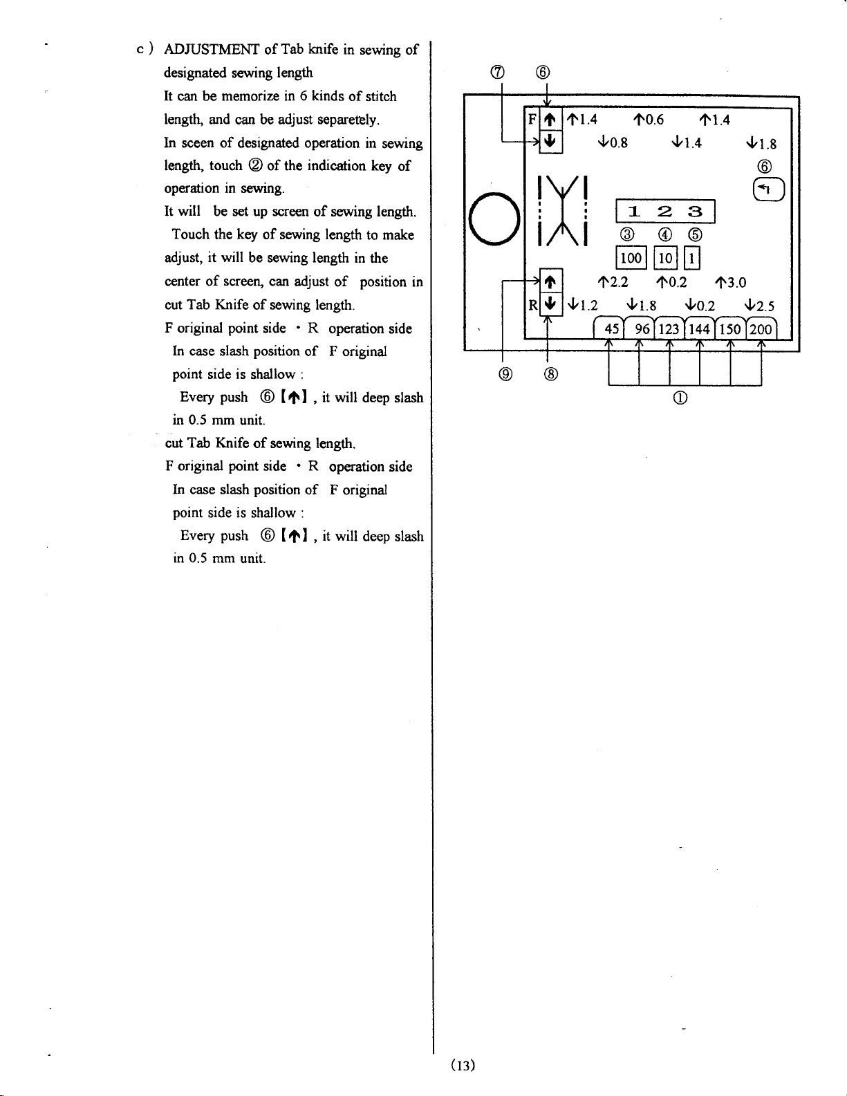
c)
ADruSTMENT
designated
It
can
length,
ln sceen of
lengttr,
operation in sewing.
will
It
Touch
adjust,
center of screeq can
cut Tab
F
original
ln
point
Every
in 0.5 mm
cut
F original
In case slash
point
in 0.5
memorize in
be
and can be adjust separetbly.
touch
be set up screen
the
it will
Knife
point
case slash
side is
push
Tab Knife
point
side is shallow :
push
Every
mm unit.
knife
Tab
of
sewing
length
6 kinds
designated operation in
of the
@
key
of sewing length
be sewing length
adjust
sewing length.
of
side . R
position
shallow
@ tOI
unit.
of sewing length.
.
side
position
trt l
@
in
of stitch
indic*ion
of sewing length.
in
of
operation
of F
original
:
it will
,
R
operation side
of F original
it will
,
sewing
position
deep slash
deep
of
sewing
key
of
to make
the
side
slash
in
@@
Ol.4
ltt0.6
go.s
,t
Or.+
1.4
Or.e
@
f-23
@
@@
@tr8
{t.z
+2.2
gr.s
+0.2
{oz
,13.0
{z.s
(t:)
6-2)
C
@
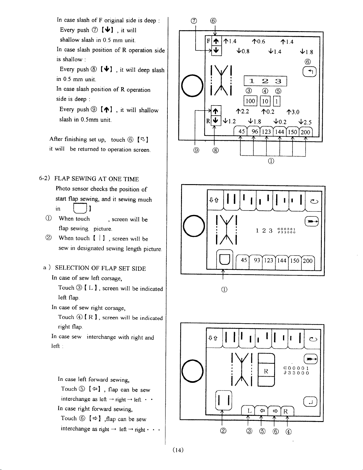
In
case
Every
shallow
In
case
is
shallow
Every
in 0.5
In
case
side
Every push
slash
After
finishing
it
will
FLAP
Photo
start
.
rn
When
flap
When
sew
slash
of F
push
@ I*l
slash in 0.5
position
slash
:
push@
mm
unit.
position
slash
is
deep :
@
in
0.5mm
set
be returned
SEWING
sensor
flap
sewing
in
checks
sewing,
l-] ,
r
(_J
touch
picture.
touch
(
designated
origural side
it witt
,
mm
of R
I9l
( rt
unit.
up,
to
AT
and it
I
it will
,
of R
it
l
,
touch
operation
ONE TIME
position
the
sewing
screen
,
screen
L
sewing
is
deep
unit.
operation
deep
operation
will
shallow
s
@ [
screen.
of
much
will
be
will
be
length
picture.
I
:
side
slash
(
\!/
A
\g/
f
1.4
Oo.e
+2.2
,f0.6
12
@
@@
[00J
[gJ u
10.2
Or.s
2 3
,t
Or.+
3
{oz
53333;
t.+
13.0
gz.s
A
SELECTION
)
In
case
Touch
left
In
case
Touch
right
In
case
left
:
In
Touch@
interchange
ln
Touch
interchange
OF FLAP
of
flap.
of
flap.
sew interchange
case left
case
left
sew
t-
@ t
sew right
n
@ t
forward
(el
as left
right
forward
@
[+l
as right
corsage,
screen
I
,
t..".n
I,
,
,flup
SET
wrll
corsage,
will
with
sewing,
flap
can be
*
right
sewing,
can
-
left
SIDE
be indicated
be indicated
right
and
sew
-
left
be sew
-
riglrt
.
a)
!Y!
tn.t
F
tl
(
l4)
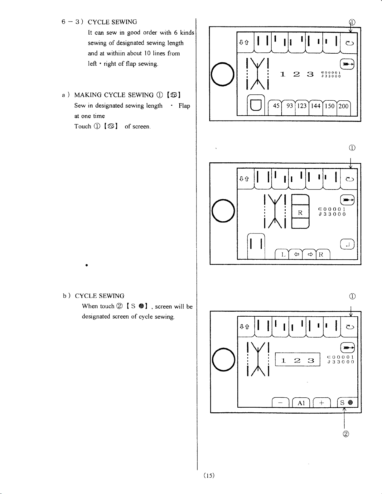
6-3)
a
uernvc
)
Sew
at one time
Touch
CycresEwrNG
good
lt
can sew
sewing of designated
and at
left . right of flap
in
withiin about
order
sewrng
10
sewing.
cYcLE sEwrNG
in
designated sewing length
of
C I5l
screen.
with
lines
C tsl
6 kinds
length
from
Flap
c
b)
CYCLE SEWING
Whentouch@
designated
tS
screen of
@l
.screenwillbe
cycle sewing.
(
r s)
1_
2
3

C
SET
)
UP
It can
be set up
3-kinds-
from
Select
were
set
about
l0 lines
Flap
sewing
c-l) MAKTNG
sET up
FOR
CYCLE
Cycle
Sewing for
.te)
(al
6-kinds
up designated
for each
and
oF
of
from
Cycle
cycl,E
SEWING
.(CI
sewing length
sewing length
left
sewing.
sEwrNG
-
right
.
of
which
in
A
I
,/a\
\,@
I
@
6l
@
@
@
@
(l)Touch
Indication
(2)
Select lst
Touch
(3)Select
@
tl I I
the
sewing
Be
indicate
and
then
(4)
Selection
of
designated
In
case
of
ILl
[RI
It
will
be
Be
set
up
In
case
of making
designated
Every
length
sewing
(5)
Selection
It
can
be
starting
If
touch
be indicated
In
case
*
will
[
I
will
be
@ tAl
of
will
@
process
Ao)
I
sewing form
touch.
d
ll
ll slantsew
tl
I
[l
ll
tl
ll
'l
il
form
the
make
of
sewrng
Flap
of
Every
Parallel
slantsew
bo*r"*
bo*
r"*
will
be
sewing
set
up.
nlap
@
lenght
sewing,
sewing
FlapI-eft
Plap rignt
indicated
corsage
sewing length.
touch
which
length
of @ Main
slow speed
of
sewing.
@,
of cancellation,
be disappeared
cancelled.
alternately.
side
set up
@,
sewing
will
(
*
and
Slow
which
O-kinds
of designated
be
of sending
I
be A
O
Cycle
Sewine
touch
sew
indicated
form
of
.
every
touch
is
sewing.
sewing
indicated.
clamp
St
Start
touch
of
of
sending
Ow
START
wilt
@
and Slow
-
A 4
in
order.
the
sewing
Sewing
@
@,
sewing
mode
until
be set
again.
Start
I
A
will
up.
I
to_/
@
fo\
v@
@@
@
@
(r6)
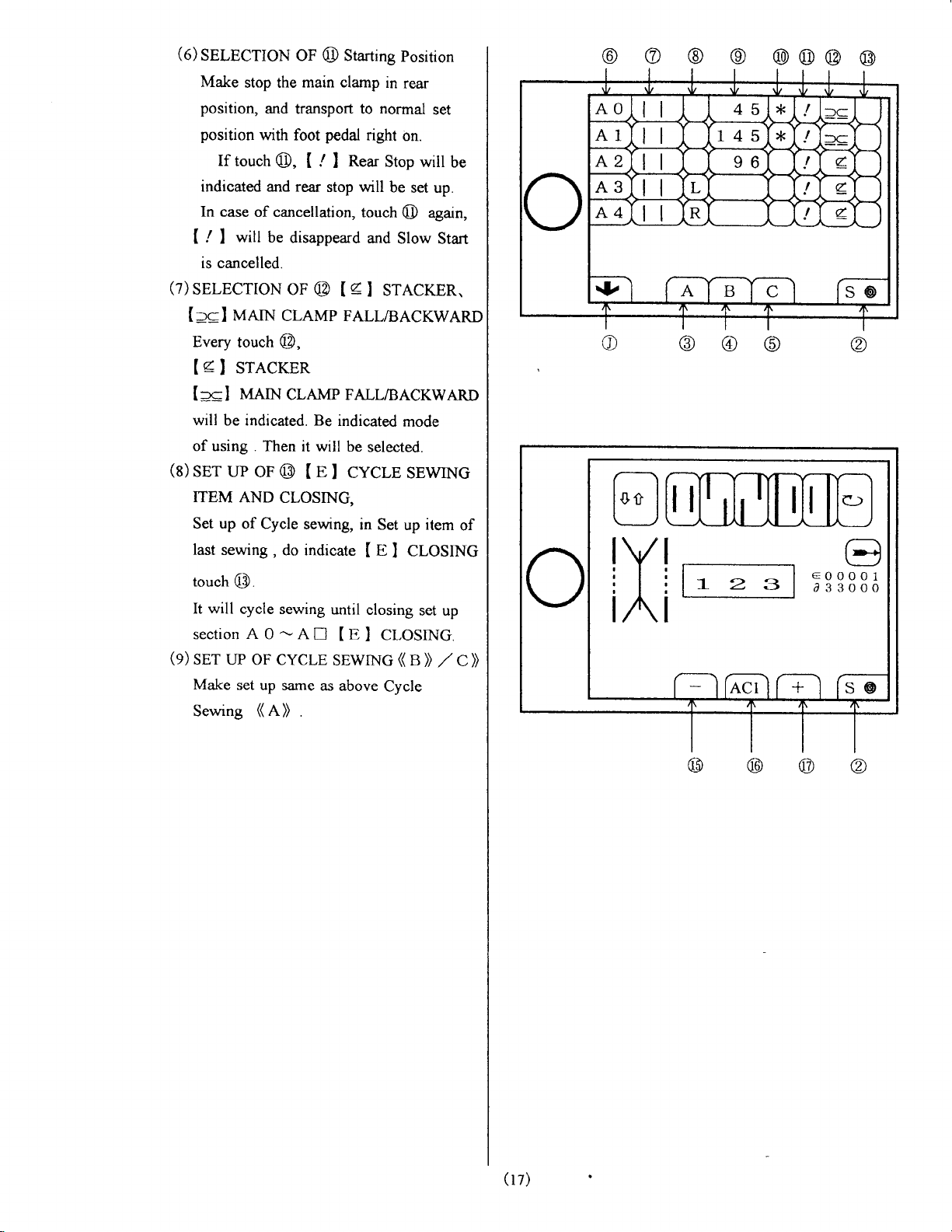
(o)
SelPCuoN
Make
stop the
position,
position
If
touch
indicated and rear
In
case ofcancellation,
will be
[ / I
is cancelled.
(7)SELECTTON
uerN
[:cl
Every
touch
(
4
srecrun
I
[::cl
will
of using .
(s)
ser uP
ITEM
Set
last
Mnnl
be indicated. Be
AND
up
of Cycle
sewing,
OF @ Starting
main clamp
and
transport to
with
foot
@, [
disappeard
OF
cLAMp
@,
cLAMP FALLTBACKwARD
Then it will
oF
@ t
CLOSING,
seu'ing,
do indicate
position
in
rear
normal
pedal
right
on.
Reat
./
I
stop will
@ Ie
Stop will
be
touch
@
and
Slow
SreCrrn.
I
set up.
again,
FALL/BAcKwARD
indicated
be
e
cycle
I
mode
selected.
sEwrNG
in Set
up
e
CLOSINC
I
I
item
set
be
Start
of
@
@@
ll
@
'r
rrl
@
@
@
@
e)
touch
It will
section A 0
(9)
SET
Make
Sewing
@
cycle sewing
-An
UP oF CYCLE
set
up same
(
A)
as
.
until
closing
(
E
CLOSTNG.
I
SEWING
above
Cycle
set up
KB))
./
C>,
r_
2
3
(rz)
 Loading...