

Mitsubishi Electric PLK-J-CU-20 Technical Manual

INDUSTRIAL SEWING MACHINE
MODEL
PLK-J-CU-20
TECHNICAL MANUAL
Control Unit
A180E780P03

I
Contents
[1] For safe use _______________________________________________ [1]-1
[2] Precautions for use _________________________________________ [2]-1
[3] Installation ________________________________________________ [3]-1
[4] Names of each part, wiring and grounding ______________________ [4]-1
[5] Confirmation _______________________________________________ [5]-1
[6] Main and Sub servo motor ________________________________ ___ [6]-1
[7] Timing chart _______________________________________________ [7]-1
[8] Customized input/output _____________________________________ [8]-1
[9] Input / Output signal ________________________________________ [9]-1
[10] What happened? Could it be an error? ________________________ [10]-1
[11] Several power supply ______________________________________ [11]-1
[12] Unit wiring diagram ________________________________________ [12]-1
[13] Connectors layout _________________________________________ [13]-1
[14] Pin number of connectors ___________________________________ [14]-1
[15] Wiring diagram inside control box ____________________________ [15]-1
[16] Specifications _____________________________________________ [16]-1

II
Thank you for purchasing the Mitsubishi industrial sewing machine PLK-J Series.
Please read this technical manual before starting to ensure correct and long-term use.
* The contents of this manual may not be reproduced in part or whole.
* The contents of this manual are subject to change without notice.
* An utmost effort has been made to cover all points of operation in this manual. Contact
Mitsubishi if you have any questions regarding the contents.
COPYRIGHT(C) 2017 MITSUBISHI ELECTRIC CORPORATION

[1] ‐ 1
[1] For safe use
■ For safe use
Always observe the following matters to safely use the Mitsubishi industrial electronic sewing machine PLK-J Series.
Before starting
Before using this control unit, read all of the technical manuals carefully, and correctly use the unit following
the manual. Also read the "Mitsubishi Industrial Sewing Machine Technical Manual <Sewing Machine Head>"
for details on the general configuration and sewing machine head.
Application and purpose
This control unit is designed to drive and control the Mitsubishi industrial electronic sewing machine PLK-J
Series. Do not use this control unit for other applications or purposes. Do not use this control unit until it has
been confirmed that safety measures have been accurately taken for the installed electronic sewing machine
head section.
Working environment
Please use this control unit in the industrial setting only. And do not use this control unit in the following type of
environment.
(1) Power voltage
* Where the voltage fluctuation exceeds ±10% of the rated voltage.
* Where the specified power capacity (Refer to page [4] - 2) cannot be ensured.
(2) Magnetic noise
* Where strong fields or magnetic fields are generated, such as near a high-output high frequency
oscillating machine or high frequency welder.
(3) Temperature and humidity
* Where the ambient temperature is 35°C or more and 5°C or less.
* Where the unit will be subject to direct sunlight, or outdoors.
* Near sources of heat, such as heating appliances.
* Where the relative humidity is 45% or less, or 85% or more, and where dew may condense.
(4) Atmosphere
* In an atmosphere containing dust or corrosive gases, etc.
* In a flammable gas or explosive environment.
(5) Vibration
* If excessive vibration could occur when installed on the sewing machine, separately install the control
box.
■ Installation
Control box
Correctly install the control box according to this manual.
Accessories
Always disconnect the control unit from the main power supply before installing the accessories listed in this
manual. “Turn the power switch OFF, and disconnect the plug from the socket (power supply line).”
Cable
(1) Lay the connection cables so that excessive force will not be applied during operation. Do not excessively
bend the cables.
(2) Cables laid near operating machine sections must be separated by at least 25mm.
(3) Before connecting the power cable to the control box, confirm that the power voltage matches the
specifications given on the control box's rating nameplate and factory shipment voltage nameplate. Connect
the cable to the indicated positions, and then supply the power. When using a power unit, connect the cable
to the power unit and supply the power. In addition, when using a power unit, confirm that the power
voltage matches the specifications given on the power unit's rating nameplate. Turn the power switch OFF
before making any connections.
Grounding
Always ground the power cord's grounding wire.
Enclosed units and accessories
Connect the electrical enclosed units and accessories only to the positions indicated in the manual.
[1] ‐ 2
Removal
(1) Always turn the power switch OFF and disconnect the plug from the socket (power supply line) before
removing the control box.
(2) Do not pull out the cord when disconnecting the plug. Always hold the plug receptacle when disconnecting
the plug.
(3) Note that a high voltage is applied inside the control panel, so always turn the power OFF and wait at
least ten minutes before opening the control box cover.
■ NOTICE CONCERNING MARKING
(1) Electronic sewing machine PLK-J series are applied to CE conformity marking by installing the exclusive
device [PLK-J-CE] and [PLK-J-ACR].
When the products are used in the EU region, these devices are necessary to be installed.
(2) Electronic sewing machine should be use limited to the industrial areas even though above-mentioned
countermeasure is done.
[Warning] Use in residential areas may cause interference.
■ Maintenance, inspection and repairs
(1) Follow this manual when carrying out maintenance or inspections related to this control unit.
(2) This unit must be repaired, serviced and inspected only by a worker that has received special training.
(3) Always turn the power OFF before replacing the needle or bobbin, etc., on the head.
(4) Use genuine replacement parts for repairs and maintenance.
■ Other safety measures
(1) Keep fingers away from all moving machine parts (especially around the sewing machine needle, etc.).
(2) Never drop the control unit, or place objects in the clearances.
(3) Do not operate the sewing machine without the protective parts such as the cover, or protection devices
such as the safety breaker.
(4) If any damage is observed in the control unit, if the unit does not operate correctly, or if the operation is
suspicious, always suspend operation. Only operate the machine after the supervisor has adjusted, repaired
or inspected the machine.
(5) The user must not make improvements or changes without instruction from Mitsubishi.
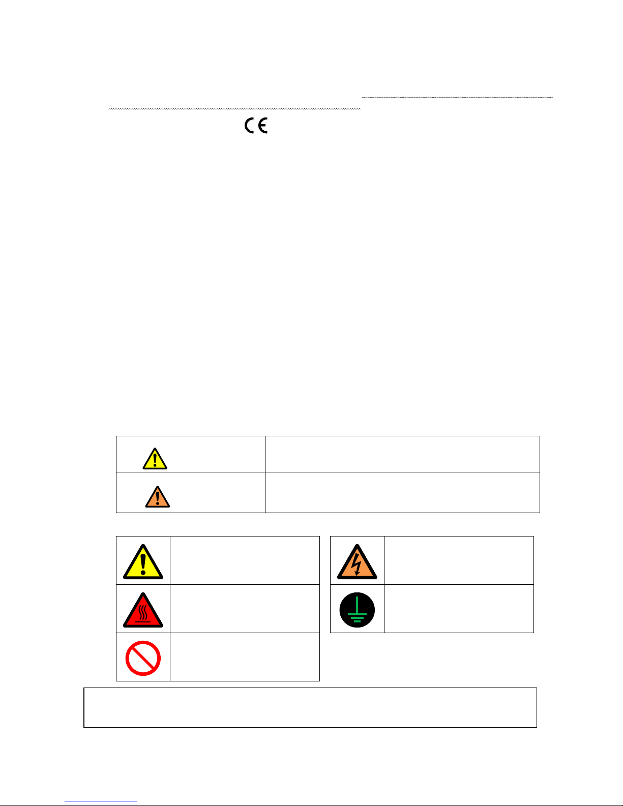
■ Caution displays and danger displays
(1)In this manual, the dangers and danger levels that arise with incorrect handling are classified using the
following displays.
Warning
The warning display shows that incorrect handling can lead to
death or serious injuries.
Caution
The caution display shows that incorrect handling can lead to
injuries or damages to your house, household goods, and
others.
(2)The meanings of these symbols are as follows.
This symbol indicates that the
instructions must be followed.
This symbol indicates an
electrical hazard or caution
(electric shock caution).
This symbol indicates hot
temperature requiring caution.
This symbol indicates that
ground wire connection is
required.
This symbol indicates a
prohibited action.
* Always deliver this manual to the end user.
* Store this manual nearby where it can be referred to when necessary.
[2] ‐ 1
[2] Precautions for use
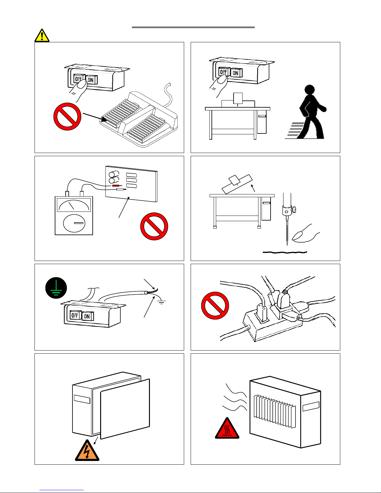
Warning
1. Do not place foot on the foot switch when turning the power
ON.
2. Always turn the power OFF when leaving the sewing
machine.
3. Do not inspect the control circuit with a tester.
The tester voltage could be applied on the semiconductor
parts, and cause damage.
4. Always turn the power switch OFF before tilting the sewing
machine head, replacing the needle, or passing thread
through the needle.
5. Always ground the grounding wire.
Always ground the provided grounding wire
(green(green/yellow)).
6. Do not use excessive wiring.
7. A high voltage is applied inside creating a hazardous state,
so always turn the power OFF and wait ten minutes before
opening the cover.
High voltage risk
8. Radiation fins and other parts may be hot. Do not touch the
parts.
Control circuit
Green
(Green/yellow)
Power supply
[2] ‐ 2
9. The sewing machine will coast to a stop when the power is turned OFF or a power failure occurs during sewing machine
operation.
10. Always align the connector shape and direction, and securely insert the connector.
11. If the position detector's connector dislocates, or the sewing machine is completely locked, the motor will be turned OFF
automatically for a set time to prevent burning. (Note that the motor may not turn OFF if there is incomplete locking or an
overload.) When the fault has been recovered, turn the power OFF and ON once to resume normal operation. The same type
of operation will take place if a detector fault or disconnection occurs.
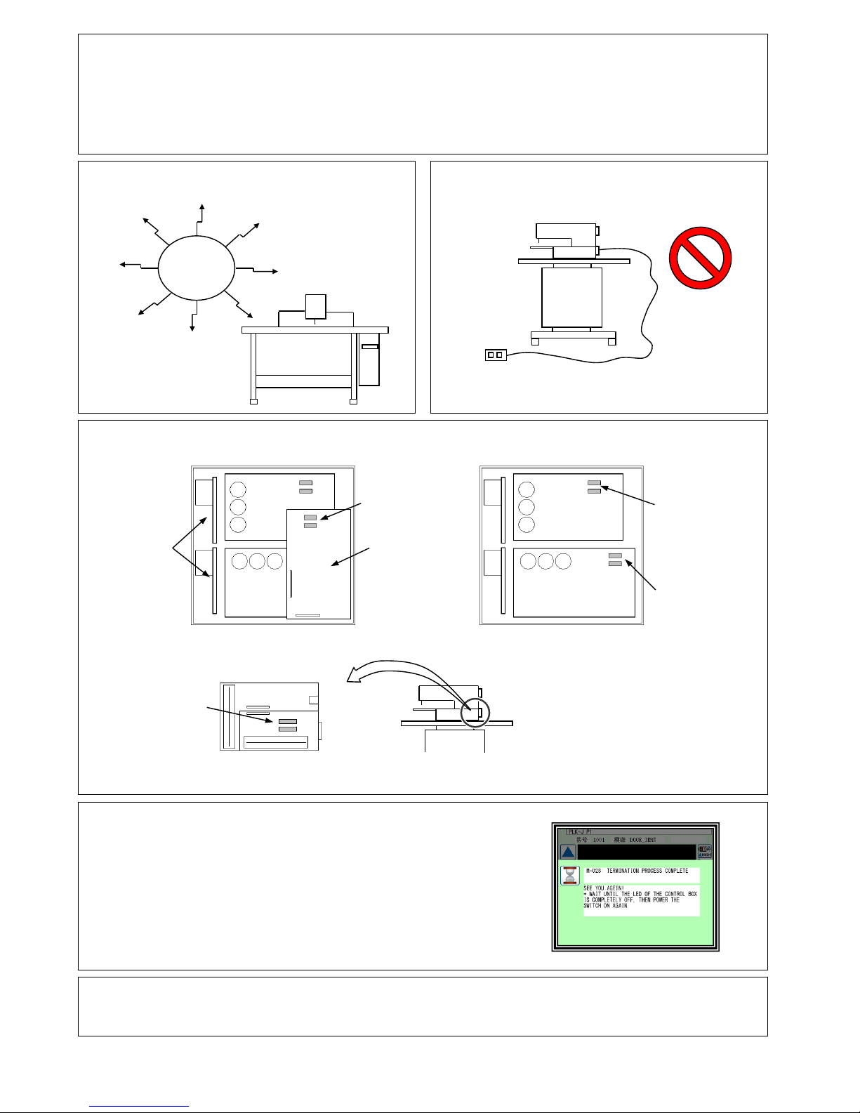
12.Use the machine away from strong noise sources such as
high frequency welders.
13. When connecting the external switch to an optional
connector, etc., keep the signal wire as short as possible. A
long wire could cause malfunctions.
Use a shielded wire for the signal wire when possible.
14. If the fuse blows, remove the cause, and replace the blown fuse with one having the same capacity.
(View from the front with cover removed) (View from the front
with the cover and CPU removed)
I/F board located
on back of machine head
15. Attention when power supply is turned on again
Please make sure not to turn on the power supply switch until after
the LED on the front panel of the control box has completely turned off.
(Please do not turn on the power supply again while displaying
the screen of the operation panel.)
* Please note that if power supply is turned on again while LED still turns on,
clamp outputs (O4, O5 port) may go down.
16. When the value of the sewing area limit is changed or the limit setting is deactivated, note the collision and
take care safely.
Also when using it outside the range where the mechanism can be operated, it cannot assume the responsibility for
all problems caused by it.
Noise
CPU Board
PMD Board
PWR Board
2.5A fuse (two fuses)
20A fuse (two fuses)
20A fuse (two fuses)
8A fuse (two fuses)
SRV Board
[3] ‐ 1
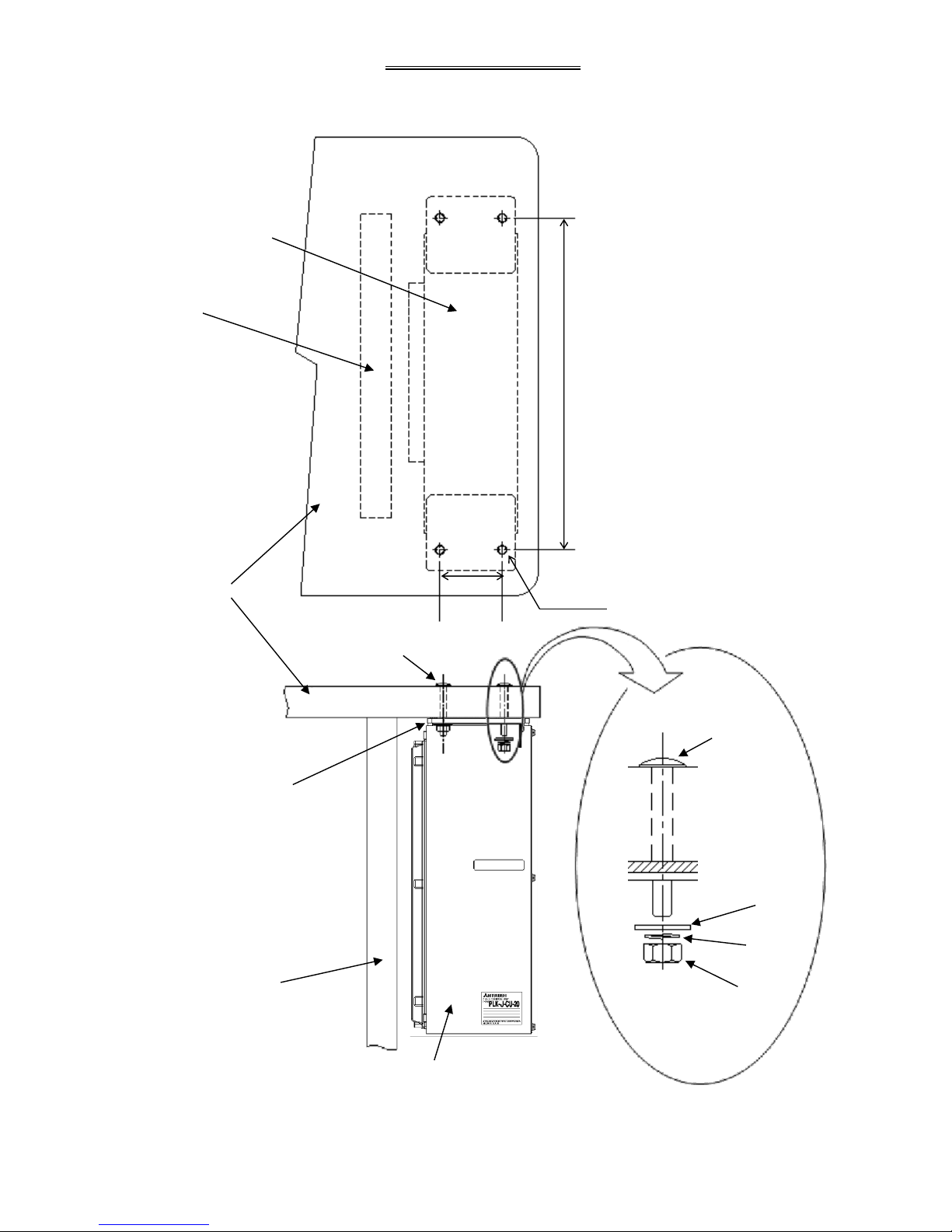
[3] Installation
1. Installing the control box
Top view of control box
installation area
Front view of control box
installation area
●Insert the four bolts into the holes on the
top plate and install the control box.
80
427
Top plate
Damper
cushion
Control box
Leg
Nuts
Spring
washer
Washer
Installation bolt
(M8 x 60)
Leg
Control box
Installation bolt
(Fix at four positions)
4-Ø9
[4] ‐ 1
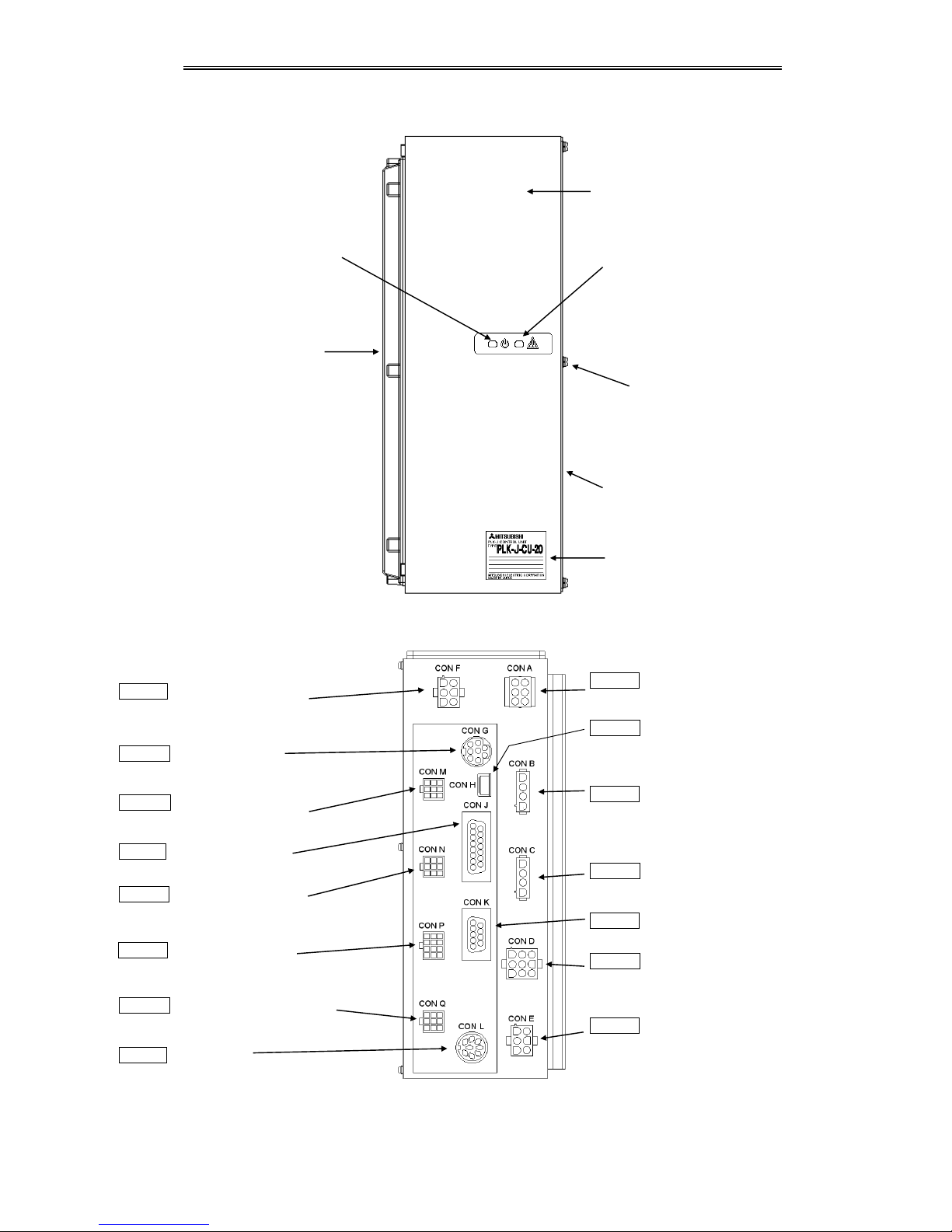
[4] Names of each part, wiring and grounding
1.Front side
2.Back side
CON F Power supply
(Connect to power switch box)
CON G Operation panel
CON M Main servo encoder
(Connect to spindle servo motor)
CON J I/F board signal
(Connect to I/F board (MIF))
CON N Sub servo encoder
(Connect to spindle servo motor)
CON P XY axis encoder
(Connect to XY axis stepping motor)
CON Q PF axis encoder
(Connect to PF axis stepping motor)
CON L Foot switch
Heat sink
Power
LED (green)
Warning
LED (red)
Front panel
Cover installation screw
(M4 screw)
Cover
CON A I/F board power
“Connect to I/F board (MIF) “
CON H general purpose port
(Connect to PC)
CON B Main servo motor
(Connect to spindle servo motor)
CON C sub servo motor
(Connect to spindle servo motor)
CON K universal serial communication port
CON D XY axis stepping motor
(Connect to sewing machine head stepping
motor)
CON E PF axis stepping motor
(Connect to sewing machine head PF axis
stepping motor)
Rating plate
Caution: Be sure to connect all connectors before turning ON the power. Connect each connector fully to ensure
sufficient contact. Refer to “section [12].”
[4] ‐ 2
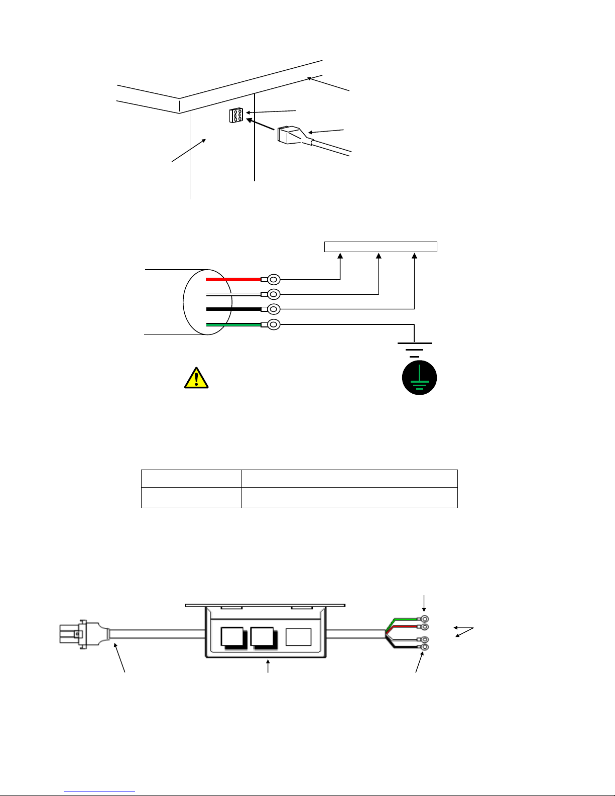
3. Connecting the power connector
Caution1: Always confirm the connector shape and insertion orientation
and completely insert the power connector into the control box.
Always turn the power OFF before connecting the connector.
Caution2: Please do not bundle the power cable and other cables
together. It may cause of malfunction by the influence of the
power supply noise etc.
4. Connecting the 3-phase power supply
3-phase power supply R-phase S-phase T-phase
Push-button switch cord
Warning
Always connect the green wire to the grounding terminal.
Consult with your electrician for details on the grounding wire.
5. Power capacity
Use a fuse or safety breaker on the power supply.
Power supply
Recommended current capacity value
3-phase 200V
10A
6. Using the 3-phase 200V control box with single-phase 200 to 220V
Connect power supply to the "red" and "white" lead wires for the push-button switch.
The black wire is not used, so insulate it by wrapping insulation tape, etc., around it.
Always ground the green grounding wire.
Connect to ground
Connection connector to control box Push-button switch
Top plate
Control box power
Power connector (6-pole)
Control box
Red (black)
White (brown)
Black (blue)
Green (green/yellow)
Green
Red
White
Black
Do not connect
(Accurately insulate with tape.)
Connect these lead
wires to the power
supply.
OFF ON
[5] ‐ 1
[5] Confirmation
1. Before turning the switch ON
(1)Are the power and capacity correct?
(2)Are the connectors correctly inserted? (Refer to “section [12]”.)
* Power connector from push-button switch
* Connector for connection with sewing machine
* Operation panel connector
* Foot switch connector
* Other connectors “I/F board (MIF), etc.”
(3)Does the hand pulley turn easily?
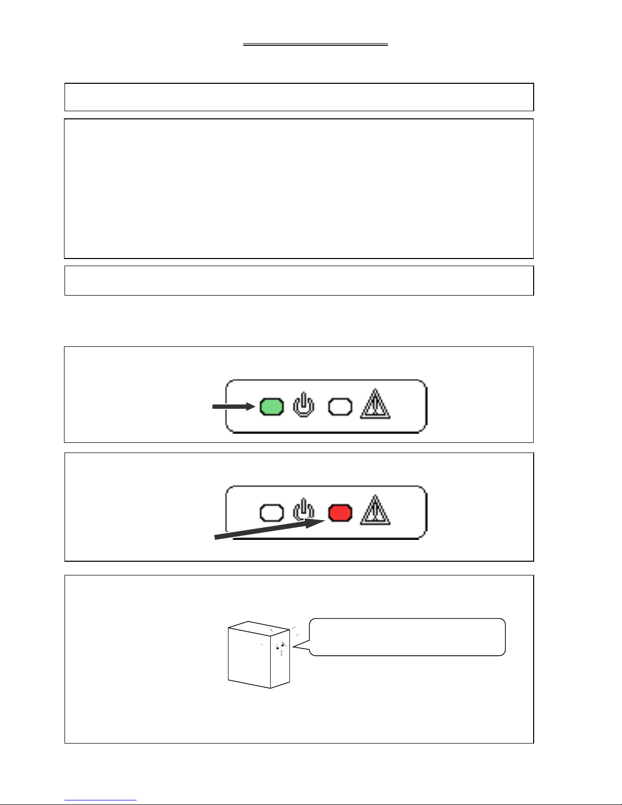
2. After turning the switch ON
(1)Is the front panel power LED (green) on?
(2)Is the front panel warning LED (red) on or flickering?
(3)Is there any heating, odors or abnormal noise from the motor or control box?
● When you turn ON the power, a click noise comes from inside the control box.
This noises are not abnormal.
Turn the sewing machine OFF and contact your
dealer if there is any heating, odors or abnormal noise.
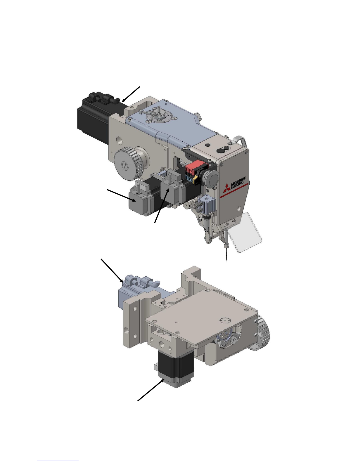
[6] ‐ 1
PF motor
PF motor
[6] Main and Sub servo motor
Main and Sub servo motor are driven by independent.
Please note the timing for motion of each motors.
Refer the other technical manual "Sewing Machine Head" about details.
Main axis motor
Thread trimming motor (P1 axis)
Digital tension motor
Main servo motor
Sub servo motor
Digital tension motor
(P2 axis)
[7] ‐ 1
[7] Timing chart
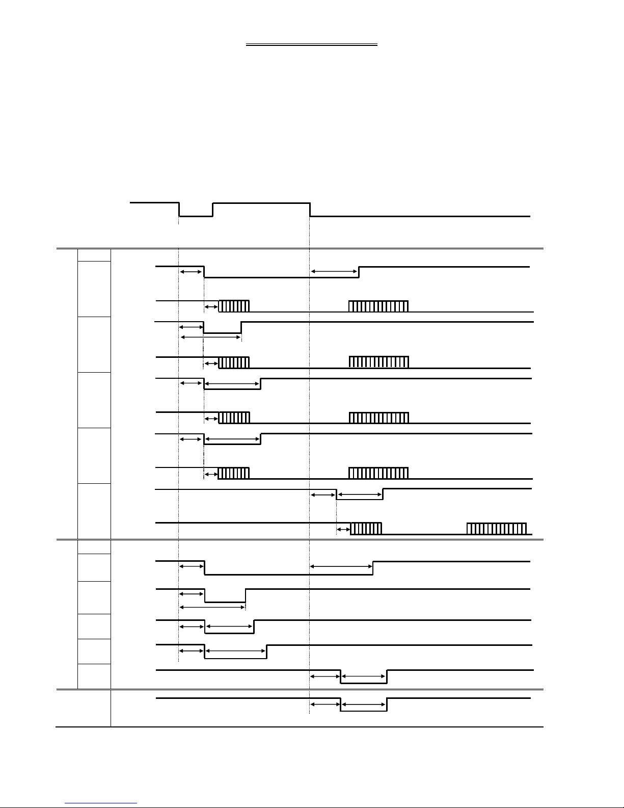
1. Thread trimming timing chart
·Timing for thread trimming output [T] :
Program mode [Thread trimming/release timing] -- [LTM] T1~T5
Program mode [Thread trimming/release timing] -- [TRS] msec / deg
Program mode [Thread trimming/release timing] -- [TRE] msec / deg
·Timing for thread release output [L] :
Program mode [Thread trimming/release timing] -- [LLM] L1~L5
Program mode [Thread trimming/release timing] -- [LRS] msec / deg
Program mode [Thread trimming/release timing] -- [LRE] msec / deg
·Timing for wiper output [W] :
Program mode [Wiper] -- [W1] msec
Program mode [Wiper] -- [W2] msec
Needle up
position UP
Thread trimming output
signal
[T]
LTM
T1
T2
T3
T4
T5
Thread release output
signal
[L]
LLM
L1
L2
L3
L4
L5
Wiper
Output
signal W
*1: Thread trimming motor start to move after delay time (about 25 msec) of Trim output turning ON.
Note: Thread trimming motor is driven by independent.
Please note the setting about trim speed and trim timing.
TRS (deg)
TRE (ms)
TRS (deg)
TRE (deg)
TRS (deg)
TRS (ms)
T:Thread trimming output signal
*1
ON
T1
T2
Starting motor operation
*1
Waiting
A+:Thread trimming Motor current
T
A+
*1
*1
UP1
UP2
ON
*1
L:Thread release output signal
L
L
L
L
L
W
T
A+
T
A+
W:wiper output signal
T
A+
T
A+
TRE (ms)
TRE (ms)
TRE (ms)
TRS (ms)
LRS (deg)
LRS (deg)
LRS (deg)
LRS (ms)
LRE (ms)
LRE (ms)
LRE (ms)
LRE (ms)
LRS (ms)
LRE (deg)
W1 (ms)
W2 (ms)
Starting motor operation
Waiting
Waiting
Waiting
Starting motor operation
Starting motor operation
End of motor operation
End of motor operation
End of motor operation
End of motor
operation
Waiting
Starting motor operation
End of motor operation
[7] ‐ 2
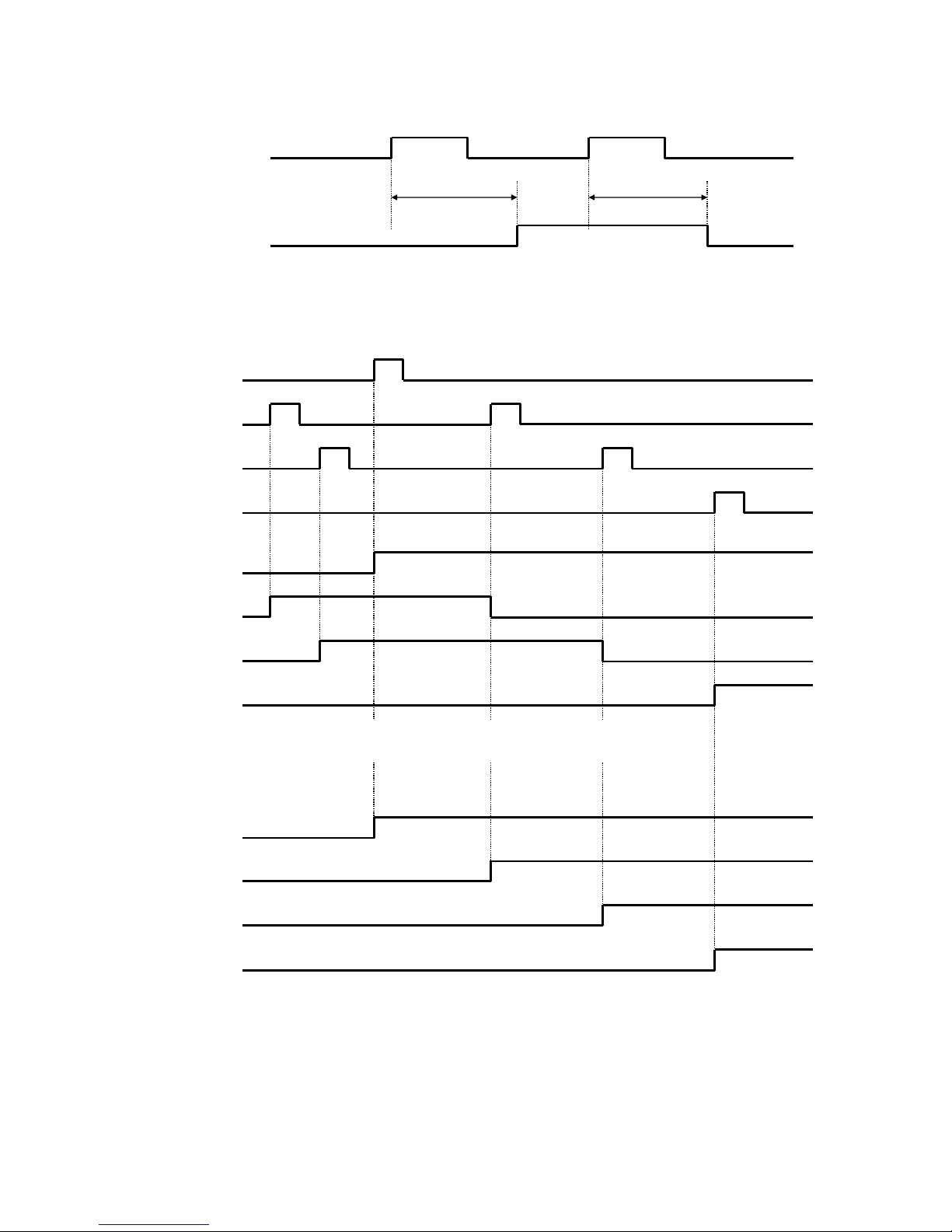
2. Timing chart for [Clamp of output ON/OFF delay setting]
Clamp input 1 to 4
IF1 to IF4
Clamp output 1 to 4
OF1 to OF4
3. Timing chart for [Priority of clamp]
Clamp input 1
IF1
Clamp input 2
IF2
Clamp input 3
IF3
Clamp input 4
IF4
[WHY]=[OFF]
Clamp output 1
OF1
Clamp output 2
OF2
Clamp output 3
OF3
Clamp output 4
OF4
Note: [WHY] = [OFF]
*The clamp input signal [IF1],[IF2],[IF3],[IF4] is validated.
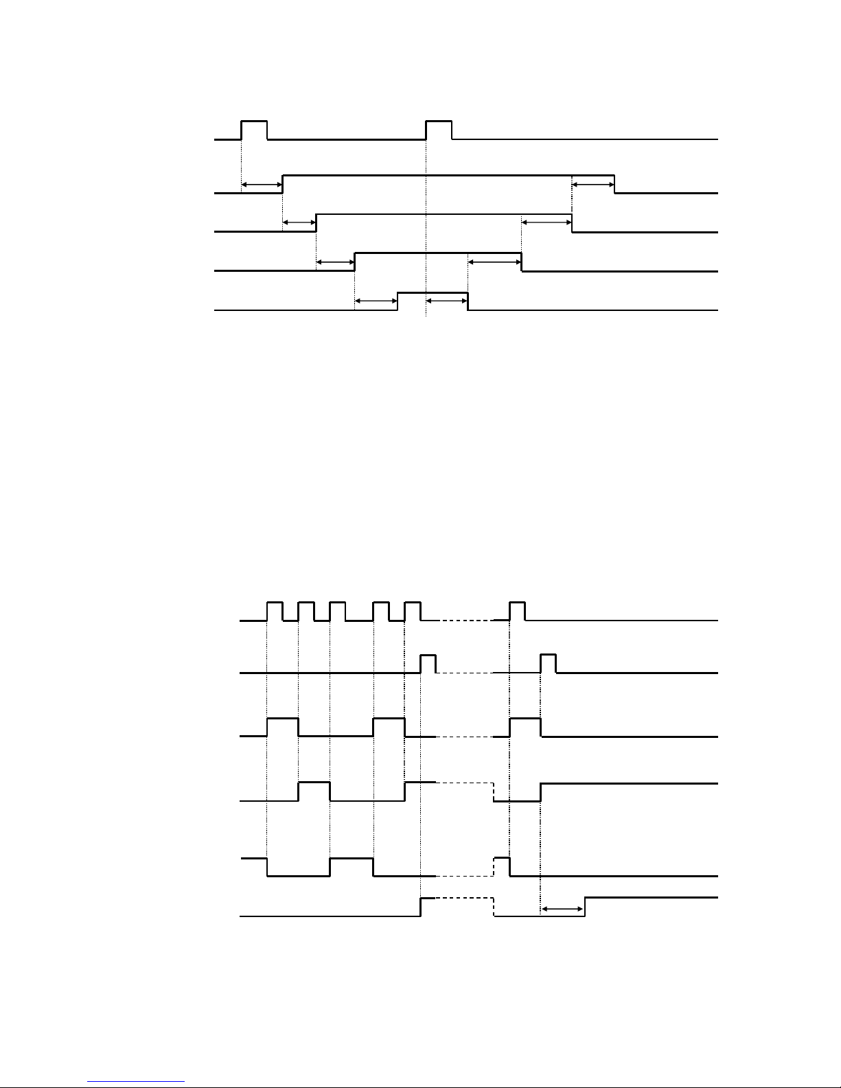
[WHY] = [ON]
Clamp output 1
OF1
Clamp output 2
OF2
Clamp output 3
OF3
Clamp output 4
OF4
Note: [WHY]=[ON]
The clamp input signal [IF2],[IF3],[IF4] is invalidated when clamp output 1 is not ON.
The clamp input signal [IF2] is validated when clamp output 1 is ON.
The clamp input signal [IF3] is validated when clamp output 2 is ON.
The clamp input signal [IF4] is validated when clamp output 3 is ON.
ON
ON
ON
ON
ON
ON
ON
ON
ON
ON
ON
ON
ON
ON
ON
ON
1A to 4A
1B to 4B
[7] ‐ 3
4. Timing chart for
[Clamp link setting (CF)] = ON, [Valid Number of clamp setting (FN)] = 4
Clamp input 1
IF1
Clamp output 1
OF1
Clamp output 2
OF2
Clamp output 3
OF3
Clamp output 4
OF4
Note: Halt switch is validated.
5. Timing chart for
[Selection of pneumatic pressure two-step (AF2)] = ON
Can not use other function in “Work holder” mode.
Pneumatic pressure
two-step clamp
input signal A2F
Start
input signal SRT
Pneumatic pressure
two-step clamp
low pressure output AFL
Pneumatic pressure
two-step clamp
high pressure output AFH
Pneumatic pressure
two-step clamp
eject pressure output AFE
Movement of
sewing machine
ON
ON
ON
ON
ON
ON
1A
2A
3A
4A
4B
3B
2B
1B
ON
1T
ON
ON
ON
ON
ON
ON
ON
ON
ON
ON
ON
ON
ON
ON
ON
ON
[7] ‐ 4
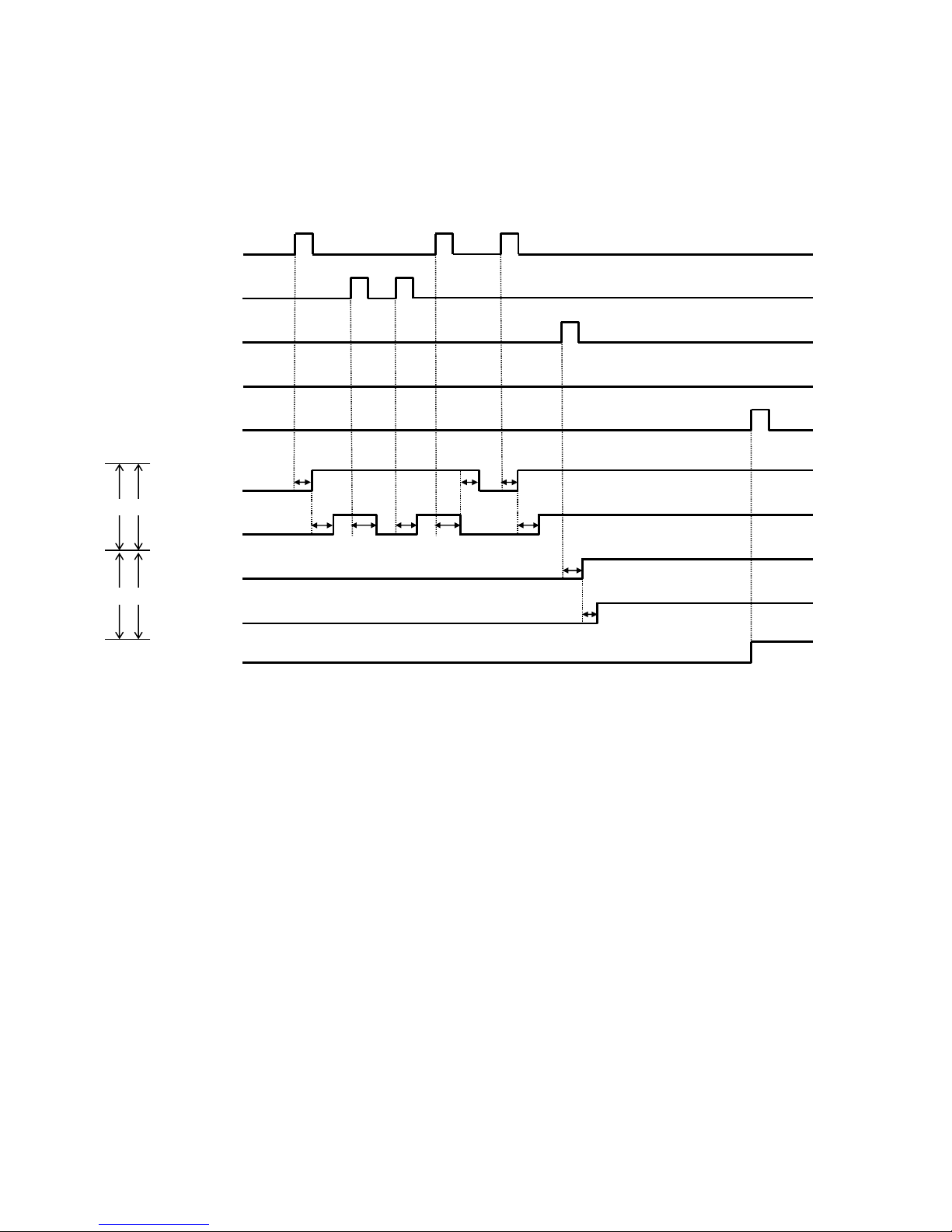
6. The divisions of clamp setting [OFB] = 4
Setting of [FN],[CF] is invalidated when above setting.
Clamp(O1,O2),(O3,O4) is link movement when above setting.
The presser block to be used is [F2BN] and can be set.
[WHY] = OF,[OFB] = 4,[F2BN] = 2
When not using the clamp step input.
Clamp input 1
IF1
Clamp input 2
IF2
Clamp input 3
IF3
Clamp input 4
IF4
Start input signal
SRT
Clamp output 1
OF1
Clamp output 2
OF2
Clamp output 3
OF3
Clamp output 4
OF4
Movement of
sewing machine
1 2
ON
ON
ON
ON
ON
4A
3A
2A
1A
ON
ON
ON
ON
2 2
←Block number of clamp
←Number of clamps
2B
2A
ON
2B
2A
ON
ON
ON
1A
ON
1B
ON
 Loading...