

Page 1

INDUSTRIAL SEWING MACHINE
MODEL
PLK-G-PAL
TECHNICAL MANUAL
Operation Panel
A180E606P12
Page 2

Page 3

Contents
[1] For safe use ____________________________________________ [1]-1
[2] Precautions for use ______________________________________ [2]-1
[3] Explanations of basic screen, icons and operation ____________[3]-1
1.Screen configuration.........................................................................................[3]-1
2.Explanations of Standard screen 1...................................................................[3]-2
3.Explanations of Standard screen 2...................................................................[3]-3
4.The Up Counter screen is explained below ...................................................... [3]-3
5.The Bobbin Winding screen is explained below................................................ [3]-4
6.Explanations of basic icons............................................................................... [3]-4
7.Explanation of operations.................................................................................. [3]-5
8.Adjusting the Liquid Crystal Contrast................................................................ [3]-6
[4] Sewing Data Compatibility ________________________________ [4]-1
[5] Reading, writing and erasing data __________________________ [5]-1
1.USB...................................................................................................................[5]-1
2.Reading............................................................................................................. [5]-2
3.Writing............................................................................................................... [5]-5
4.Erasing.............................................................................................................. [5]-6
5.Reading data with shortcut icons (Reading from internal memory) .................. [5]-7
6.Rename the data number ................................................................................. [5]-8
[6] Creating stitching data ___________________________________ [6]-1
1.Flow of data creation......................................................................................... [6]-1
2.Description of arrow input screen...................................................................... [6]-4
3.Description of menu.......................................................................................... [6]-5
4.Skip jogging....................................................................................................... [6]-6
[7] Methods of creating sewing data ___________________________ [7]-1
1.Linear input ....................................................................................................... [7]-1
2.Arc input............................................................................................................ [7]-4
3.Circle input........................................................................................................ [7]-8
4.Curve input........................................................................................................[7]-11
5.Broken line input ............................................................................................... [7]-15
6.Point input......................................................................................................... [7]-18
7.Code data input................................................................................................. [7]-20
8.Back tacking (start/end back tacking) ............................................................... [7]-25
9.Back tacking (overlap back tacking).................................................................. [7]-27
10.Multiple stitching.............................................................................................. [7]-29
11.Offset stitching (with overlap back tacking)..................................................... [7]-32
12.Zigzag stitching (with overlap back tacking).................................................... [7]-34
[8] Controlling the Presser Foot_______________________________ [8]-1
[9] Table of stitching type combinations________________________ [9]-1
[10] Call-up function ________________________________________ [10]-1
- 1 -
Page 4

[11] Modification mode ______________________________________ [11]-1
1.Main modification mode functions.....................................................................[11]-1
2.Entering the modification mode......................................................................... [11]-1
3.Quitting the modification mode.......................................................................... [11]-2
4.Changing the feed data to home position ......................................................... [11]-2
5.Confirming on the image screen....................................................................... [11]-3
6.Modifying the stitching start position................................................................. [11]-5
7.Deleting a stitch (Deleting the designated No. of stitches)................................ [11]-7
8.Deleting a stitch (Deleting all stitches after the designated position)................ [11]-9
9.Adding a stitch (Adding one stitch).................................................................... [11]-11
10.Adding a stitch (Adding the same stitch)......................................................... [11]-13
11.Modifying the stitch position (Position of subsequent data fixed).................... [11]-15
12.Modifying the stitch position (Subsequent data position moved).................... [11]-17
13.Moving a block (Changing the prior/subsequent data).................................... [11]-19
14.Moving a block (Adding new data to the prior/subsequent data).................... [11]-21
15.Modifying a block 1 (Linear input)................................................................... [11]-23
16.Modifying a block 2 (Broken line, arc, curve input) ......................................... [11]-26
17.Modifying a block 3 (Zigzag input) .................................................................. [11]-32
18.Modifying a block 4 (Changing the feed data)................................................. [11]-34
19.Modifying stitch length (Designated distance modification) ............................ [11]-39
20.Modifying stitch length (All After designated stitch)......................................... [11]-41
21.Modifying material step................................................................................... [11]-43
22.Modifying the stitching speed (All sections after designated position)............ [11]-46
23.Modifying the stitching speed (N stitches after designated position) .............. [11]-48
24.Modifying code data (Adding code data)......................................................... [11]-50
25.Modifying code data (Deleting code data)....................................................... [11]-52
[12] Data conversion mode___________________________________ [12]-1
1.Main data conversion mode functions............................................................... [12]-1
2.Entering the conversion mode .......................................................................... [12]-1
3.Quitting the conversion mode ........................................................................... [12]-2
4.Confirming on the image screen (for the conversion mode)............................. [12]-2
5.Back tacking(Start/end back tacking)................................................................ [12]-3
6.Back tacking(Overlap back tacking).................................................................. [12]-5
7.Zigzag stitching................................................................................................. [12]-7
8.Scaling .............................................................................................................. [12]-9
9.Symmetrical ...................................................................................................... [12]-12
10.Rotation........................................................................................................... [12]-13
11.Multiple............................................................................................................ [12]-15
12.Offset............................................................................................................... [12]-18
[13] Function mode _________________________________________ [13]-1
1.Outline............................................................................................................... [13]-1
2.Explanation of each function mode................................................................... [13]-2
[14] Input/Output setting mode _______________________________ [14]-1
1.Outline............................................................................................................... [14]-1
2.Explanation of input/output setting mode.......................................................... [14]-2
3.Input signal setting table ................................................................................... [14]-6
4.Output signal setting table................................................................................. [14]-9
[15] Program mode _________________________________________ [15]-1
1.Setting methods................................................................................................ [15]-1
2."System, setting file write" and "Setting file read"............................................. [15]-4
- 2 -
Page 5

[16] Program mode list ______________________________________ [16]-1
1.Wiper................................................................................................................. [16]-1
2.Slow start .......................................................................................................... [16]-1
3.Clamp................................................................................................................[16]-1
4.Area limit........................................................................................................... [16]-4
5.Needle position ................................................................................................. [16]-5
6.Thread breaking sensor.................................................................................... [16]-5
7.Home position................................................................................................... [16]-5
8.Halt.................................................................................................................... [16]-7
9.Counter ............................................................................................................. [16]-7
10.Brake............................................................................................................... [16]-9
11.Presser foot..................................................................................................... [16]-9
12.Bobbin winding................................................................................................ [16]-10
13.Feed method................................................................................................... [16]-10
14.Speed.............................................................................................................. [16]-11
15.Thread trimming/Thread release.....................................................................[16]-12
16.Step................................................................................................................. [16]-13
17.Jog .................................................................................................................. [16]-13
18.Feed angle...................................................................................................... [16]-14
19.Other............................................................................................................... [16]-15
20.Pattern............................................................................................................. [16]-16
[17] Error / Message display _________________________________ [17]-1
1.[E-***] Error code............................................................................................... [17]-1
2.[M-***] Message code ....................................................................................... [17]-4
Thank you for purchasing the Mitsubishi industrial sewing machine PLK-G Series.
Please read this technical manual before starting to ensure correct and long-term
use.
* The contents of this manual may not be reproduced in part or whole.
* The contents of this manual are subject to change without notice.
* An utmost effort has been made to cover all points of operation in this manual.
Contact Mitsubishi if you have any questions regarding the contents.
COPYRIGHT(C)2011-2013 MITSUBISHI ELECTRIC CORPORATION
- 3 -
Page 6

[1] For safe use
■ For safe use
Always observe the following matters to safely use the Mitsubishi industrial electronic sewing machine PLK-G
Series.
Before starting
Before using this control unit, read all of the technical manuals carefully, and correctly use the unit
following the manual. Also read the "Mitsubishi Industrial Sewing Machine Technical Manual <Sewing
Machine Head>" for details on the general configuration and sewing machine head.
Application and purpose
This control unit is designed to drive and control the Mitsubishi industrial electronic sewing machine
PLK-G Series. Do not use this control unit for other applications or purposes. Do not use this control unit
until it has been confirmed that safety measures have been accurately taken for the installed electronic
sewing machine head section.
Working environment
Please use this control unit in the industrial setting only. And do not use this control unit in the following
type of environment.
(1) Power voltage
* Where the voltage fluctuation exceeds ±10% of the rated voltage.
* Where the specified power capacity (refer to technical manual [Control unit] page [4]-2 “5. Power
capacity”) cannot be ensured.
(2) Magnetic noise
* Where strong fields or magnetic fields are generated, such as near a high-output high frequency
oscillating machine or high frequency welder.
(3) Temperature and humidity
* Where the ambient temperature is 35°C or more and 5°C or less.
* Where the unit will be subject to direct sunlight, or outdoors.
* Near sources of heat, such as heating appliances.
* Where the relative humidity is 45% or less, or 85% or more, and where dew may condense.
(4) Atmosphere
* In an atmosphere containing dust or corrosive gases, etc.
* In a flammable gas or explosive environment.
(5) Vibration
* If excessive vibration could occur when installed on the sewing machine, separately install the
control box.
■ Installation
Control box
Correctly install the control box according to this manual.
Accessories
Always disconnect the control unit from the main power supply before installing the accessories listed in
this manual. (Turn the power switch OFF, and disconnect the plug from the socket (power supply line).)
Cable
(1) Lay the connection cables so that excessive force will not be applied during operation. Do not
excessively bend the cables.
(2) Cables laid near operating machine sections must be separated by at least 25mm.
(3) Before connecting the power cable to the control box, confirm that the power voltage matches the
specifications given on the control box's rating nameplate and factory shipment voltage nameplate.
Connect the cable to the indicated positions, and then supply the power. When using a power unit,
connect the cable to the power unit and supply the power. In addition, when using a power unit,
confirm that the power voltage matches the specifications given on the power unit's rating nameplate.
Turn the power switch OFF before making any connections.
Grounding
Always ground the power cord's grounding wire.
Enclosed units and accessories
Connect the electrical enclosed units and accessories only to the positions indicated in the manual.
[1] - 1
Page 7
Removal
(1) Always turn the power switch OFF and disconnect the plug from the socket (power supply line) before
removing the control box.
(2) Do not pull out the cord when disconnecting the plug. Always hold the plug receptacle when
disconnecting the plug.
(3) Note that a high voltage is applied inside the control panel, so always turn the power OFF and wait
at least ten minutes before opening the control box cover.
■ NOTICE CONCERNING MARKING
(1) Electronic sewing machine PLK-G series are applied to CE conformity marking by installing the
exclusive device [PLK-G-CE].
When the products are used in the EU region, these devices are necessary to be installed.
(2) Electronic sewing machine should be use limited to the industrial areas even though above-mentioned
countermeasure is done.
[Warning] Use in residential areas may cause interference.
■ Maintenance, inspection and repairs
(1) Follow this manual when carrying out maintenance or inspections related to this control unit.
(2) This unit must be repaired, serviced and inspected only by a worker that has received special training.
(3) Always turn the power OFF before replacing the needle or bobbin, etc., on the head.
(4) Use genuine replacement parts for repairs and maintenance.
■ Other safety measures
(1) Keep fingers away from all moving machine parts (especially around the sewing machine needle,
etc.).
(2) Never drop the control unit, or place objects in the clearances.
(3) Do not operate the sewing machine without the protective parts such as the cover, or protection
devices such as the safety breaker.
(4) If any damage is observed in the control unit, if the unit does not operate correctly, or if the operation
is suspicious, always suspend operation. Only operate the machine after the supervisor has adjusted,
repaired or inspected the machine.
(5) The user must not make improvements or changes without instruction from Mitsubishi.
■ Caution displays and danger displays
(1)In this manual, the dangers and danger levels that arise with incorrect handling are classified using the
following displays.
The warning display shows that incorrect handling can lead to
Warning
Caution
(2)The meanings of these symbols are as follows.
This symbol indicates that the
instructions must be followed.
This symbol indicates hot
temperature requiring caution.
This symbol indicates a
prohibited action.
death or serious injuries.
The caution display shows that incorrect handling can lead to
injuries or damages to your house, household goods, and
others.
This symbol indicates an
electrical hazard or caution
(electric shock caution).
This symbol indicates that
ground wire connection is
required.
* Always deliver this manual to the end user.
* Store this manual nearby where it can be referred to when necessary.
[1] - 2
Page 8
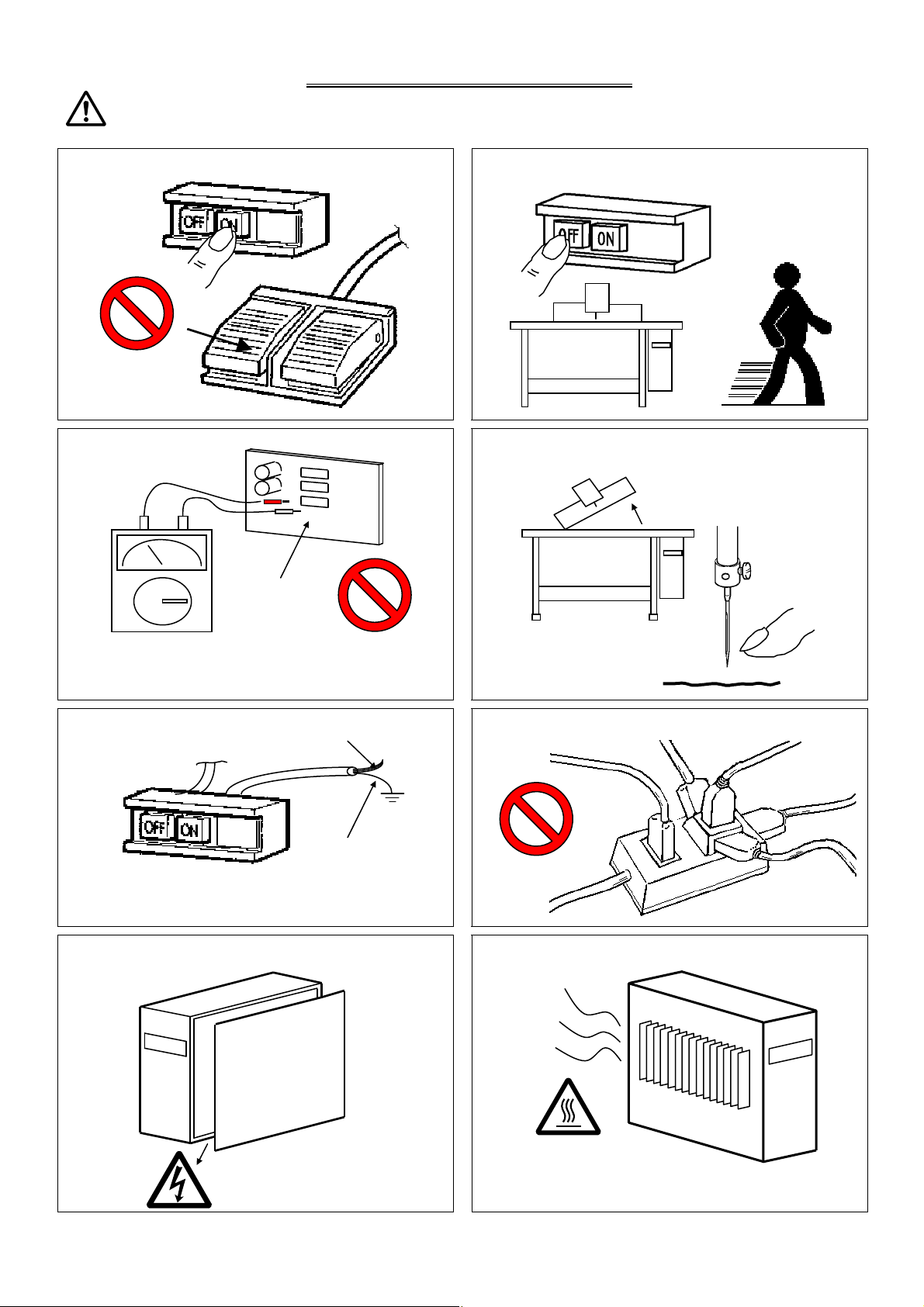
[2] Precautions for use
Warning
1. Do not place foot on the foot switch when turning the power ON.
3. Do not inspect the control circuit with a tester.
Control circuit
The tester voltage could be applied on the semiconductor
parts, and cause damage.
5. Always ground the grounding wire.
Power supply
Green
(Green/yellow)
Always ground the provided grounding wire
(green(green/yellow)).
7. A high voltage is applied inside creating a hazardous state, so
always turn the power OFF and wait ten minutes before opening
the cover.
High voltage risk
2. Always turn the power OFF when leaving the sewing machine.
4. Always turn the power switch OFF before tilting the sewing
machine head, replacing the needle, or passing thread through the
needle.
6. Do not use excessive wiring.
8. Radiation fins and other parts may be hot. Do not touch the parts.
[2] - 1
Page 9
)
)20A
)20A
)15A
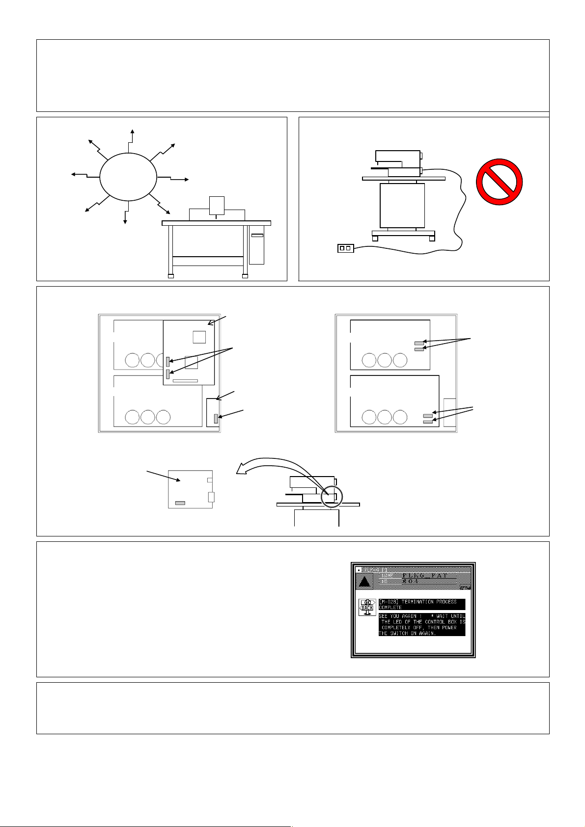
9. The sewing machine will coast to a stop when the power is turned OFF or a power failure occurs during sewing machine operation.
10. Always align the connector shape and direction, and securely insert the connector.
11. If the position detector's connector dislocates, or the sewing machine is completely locked, the motor will be turned OFF automatically for a
set time to prevent burning. (Note that the motor may not turn OFF if there is incomplete locking or an overload.) When the fault has been
recovered, turn the power OFF and ON once to resume normal operation. The same type of operation will take place if a detector fault or
disconnection occurs.
12.Use the machine away from strong noise sources such as high
frequency welders.
14. If the fuse blows, remove the cause, and replace the blown fuse with one having the same capacity.
Noise
PLK-G3-CPU
13. When connecting the external switch to an optional connector,
etc., keep the signal wire as short as possible. A long wire could
cause malfunctions.
Use a shielded wire for the signal wire when possible.
XC-G2-2B-PLK
PLK-G2-PMD
(View from the front with cover removed) (View from the front
15. Attention when power supply is turned on again
Please make sure not to turn on the power supply switch until after
the LED on the front panel of the control box has completely turned off.
(Please do not turn on the power supply again while displaying
the screen of the operation panel.)
* Please note that if power supply is turned on again while LED still turns on,
clamp outputs (O4, O5 port) may go down.
16. When the value of the sewing area limit is changed or the limit setting is deactivated, note the collision and
with the cover and CPU removed)
fuse(one fuse)
Solenoid board located
on back of machine head
2.5Afuse(two fuses
PLK-G2-PMM
8Afuse(one fuse
XC-G2-2B-PLK
PLK-G2-PMD
fuse(two fuses
fuse(two fuses
take care safely.
Also when using it outside the range where the mechanism can be operated, it can not assume the responsibility for
all problems caused by it.
[2] - 2
Page 10
[3] Explanations of basic screen, icons and operation
A
Note When power supply is turned on, if there is not sewing pattern data in the internal memory, the
message of [PATTERN DATA DOES NOT EXIST] is displayed. Press , then the standard screen
is displayed.
Note When you adjust the contrast to make the operation panel screen easier to view, refer to Chapter 8,
“Adjusting the Liquid Crystal Contrast.”(Page[3]-6)
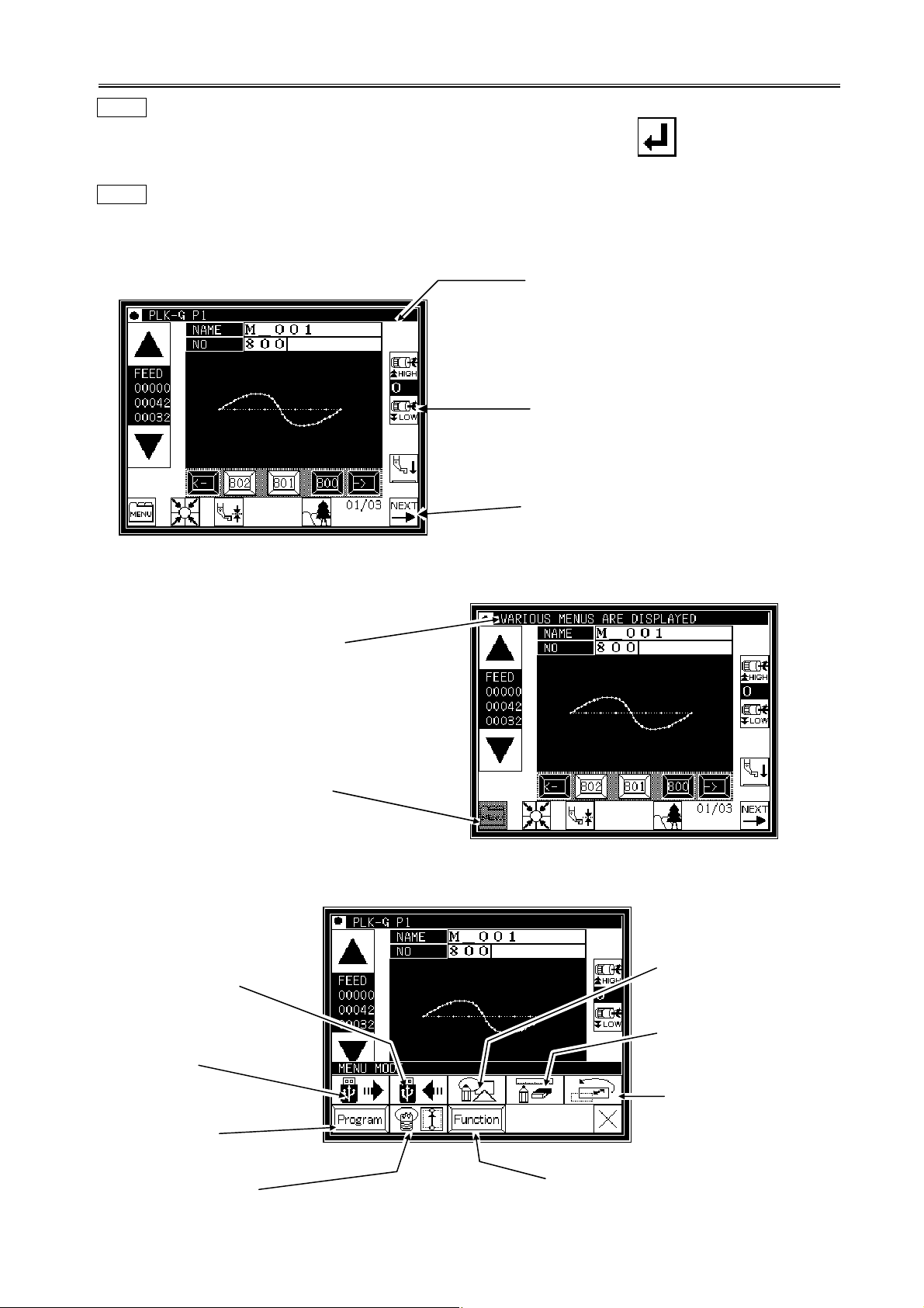
1. Screen configuration
(1)Sample screen 1 (Standard screen 1)
[Line at top of screen]
Normal: Index
(simple explanation of screen)
When any icon is pressed:
The explanation for that icon will
appear. (Refer to sample screen 2.)
Some icons will continue execution while
the icon is held down.
Most icons will execute the operation
when the finger is released.
(2)Sample screen 2 (While menu icon on Standard screen 1 is held down)
n explanation of the icon and
the screen will appear.
This icon (menu icon) is
pressed, so the icon will
be highlighted.
(3)Sample screen 3 (When menu is opened on Standard screen 1)
Writing data
Reading data
Program mode
Input/output setting
mode
Function mode
Methods of creating
stitching data
Modification mode
Data conversion
mode
[3] - 1
Page 11
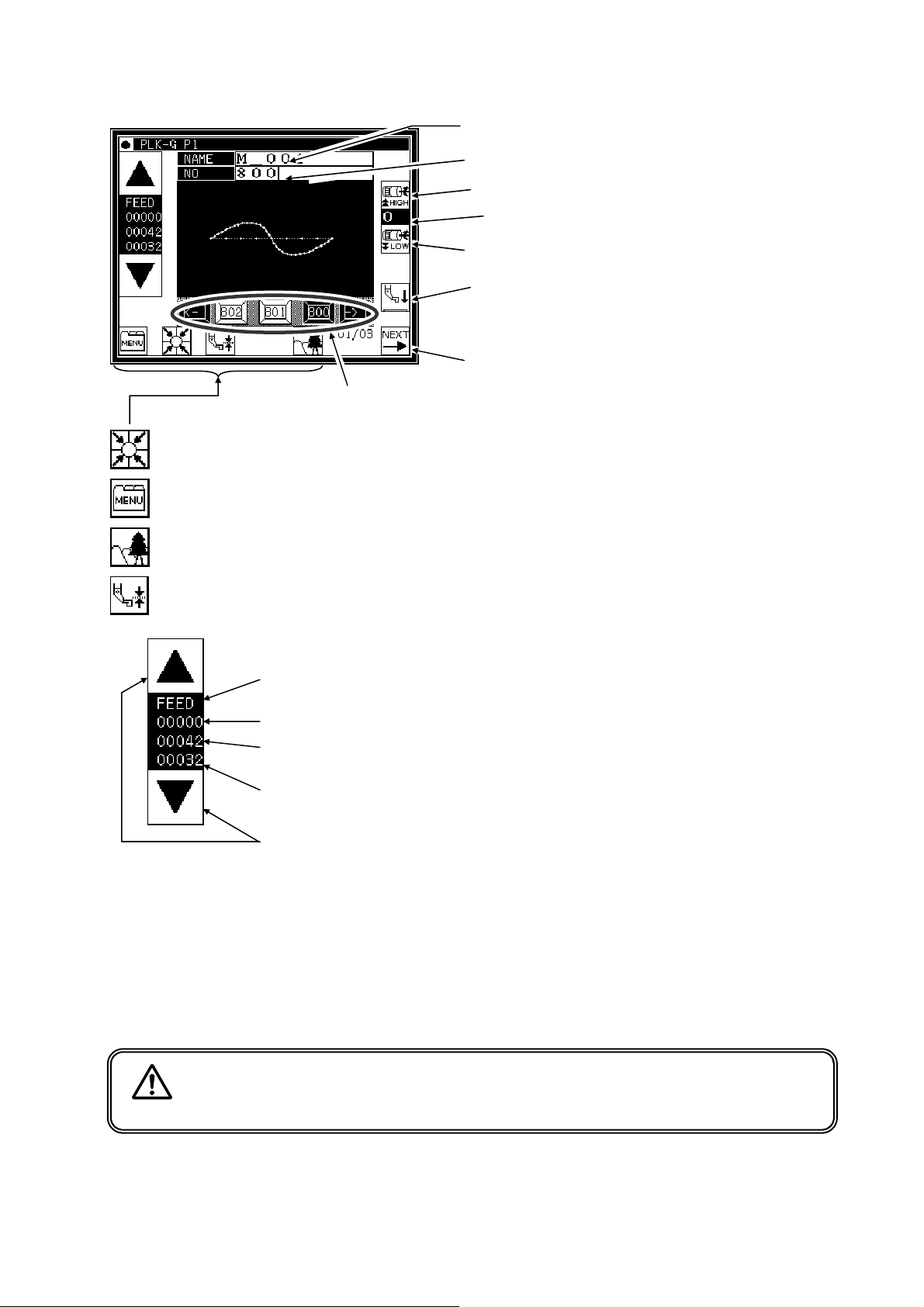
2. Explanations of Standard screen 1
The Standard screen 1 is explained in detail below.
… Home position return will be executed.
… The menu window will open
… The Image screen will open.
The stitching data is changed.
(Data in internal memory)
The pattern name is displayed. (Max : eight characters)
The pattern No. is displayed.
The sewing machine stitching speed is increased.
The current stitching speed setting value is
displayed. (0~9)
The sewing machine stitching speed is decreased.
The presser foot is moved up/down. (*1)
(The direction of the arrow (up/down) will change
according to the current state.)
Standard screen 2 opens.
The screen of setting for material thickness will open.
…
(*1) Presser bar lifting :
The stitching data type for the current work holder position is displayed.
(FEED, SEW, TRIM, etc.)
The current number of stitches is displayed.
The total number of stitches (including the feed data, thread cutting code, end code, and code
data) will be displayed.
The total number of actual stitches (excluding the feed data, thread cutting code, end code, and
code data) will be displayed.
The operation is confirmed (Jogging in forward/reverse direction)
(1) If the work holder is lowered after home position return and the forward jogging direction (upward arrow)
is pressed, the XY table (work holder) will move according to the stitching data. When the icon is
released, the operation will stop at that position. When the jog minus direction (downward arrow) is
pressed, the XY table (work holder) will move in the direction that the stitching data returns. When the
icon is released, the operation will stop at that position.
(2) Check pattern data is correct by jogging buttons, before press start pedal.
(3) During operation, the presser bar lifting will lower at stitching sections in the stitching data, and will rise
at the feed data sections.
Lowering the presser bar lifting when threading the needle is handy.
Caution
Turn the power OFF before threading the needle.
[3] - 2
Page 12
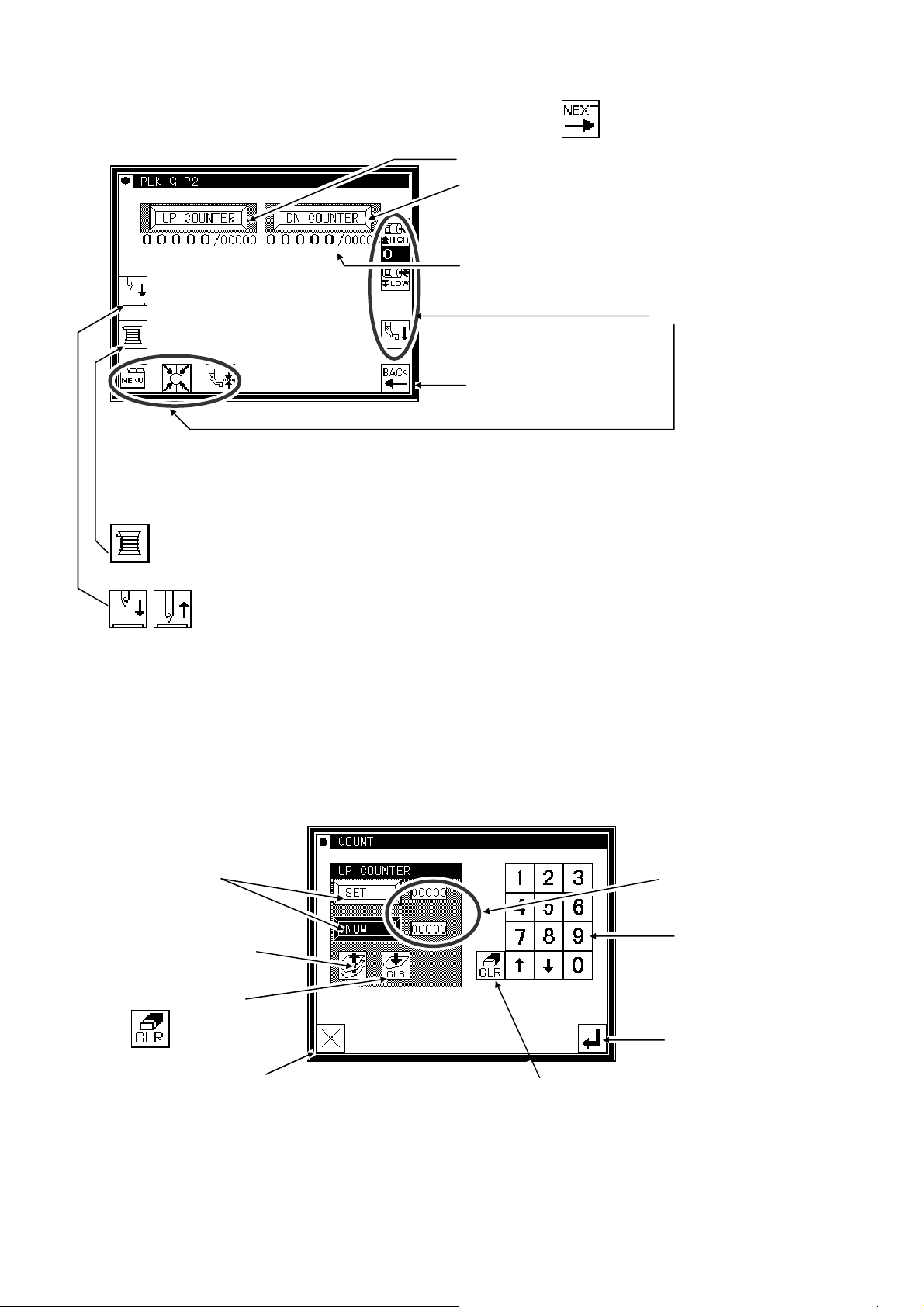
3. Explanations of Standard screen 2
Displays the Standard screen 2 from the Standard screen 1, by pressing .
The Standard screen 2 is explained in detail below.
... Bobbin winding mode (The presser bar lifting will lower, and the Bobbin Winding Setting screen will
open.) (The details are explained on the next page.)
The Up Counter screen is displayed.
The Down Counter screen is displayed.
The counter value is displayed.
(Current value/setting value)
Returns to Standard screen 1.
Same as Standard screen 1.
... Moves the needle up/down.
4. The Up Counter screen is explained below
(The Down Counter screen is the same, except for the valid/invalid icon design.)
* The methods of counting with the up counter (down counter) and clearing the counter are determined by the program
(Page[16]-7)
Displays the setting value
and current value.
Use to change the setting
value and current value.
Determines the
A set value or the selected value is cleared.
settings.(Returns to
Standard screen 2.)
mode setting.
Changes the setting value
or current value.
Changes the validity of
the up counter.
Clears the current value.
(Press to clear the
setting value.)
Returns to the previous
screen.
●When this screen is displayed, sewing cannot be performed.
[3] - 3
Page 13
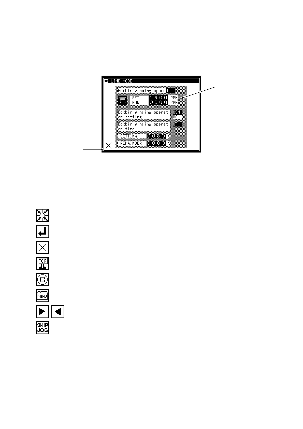
5. The Bobbin Winding screen is explained below
This screen is used to wind thread on the bobbin. (The presser bar lifting will lower when the bobbin winding
icon is pressed on the Standard screen 2.)
When the work holder switch is turned ON and the start switch is turned ON, the sewing machine will start
rotating at the set speed. The XY table will not move at this time. The sewing machine will stop at the needle
UP position when the start switch is turned OFF.
* The bobbin winding operation is determined by the program mode setting. (Page[16]-10)
Displays the current
setting value.
Exits the bobbin
winding mode.
*When exit winding mod, presser foot is raised.
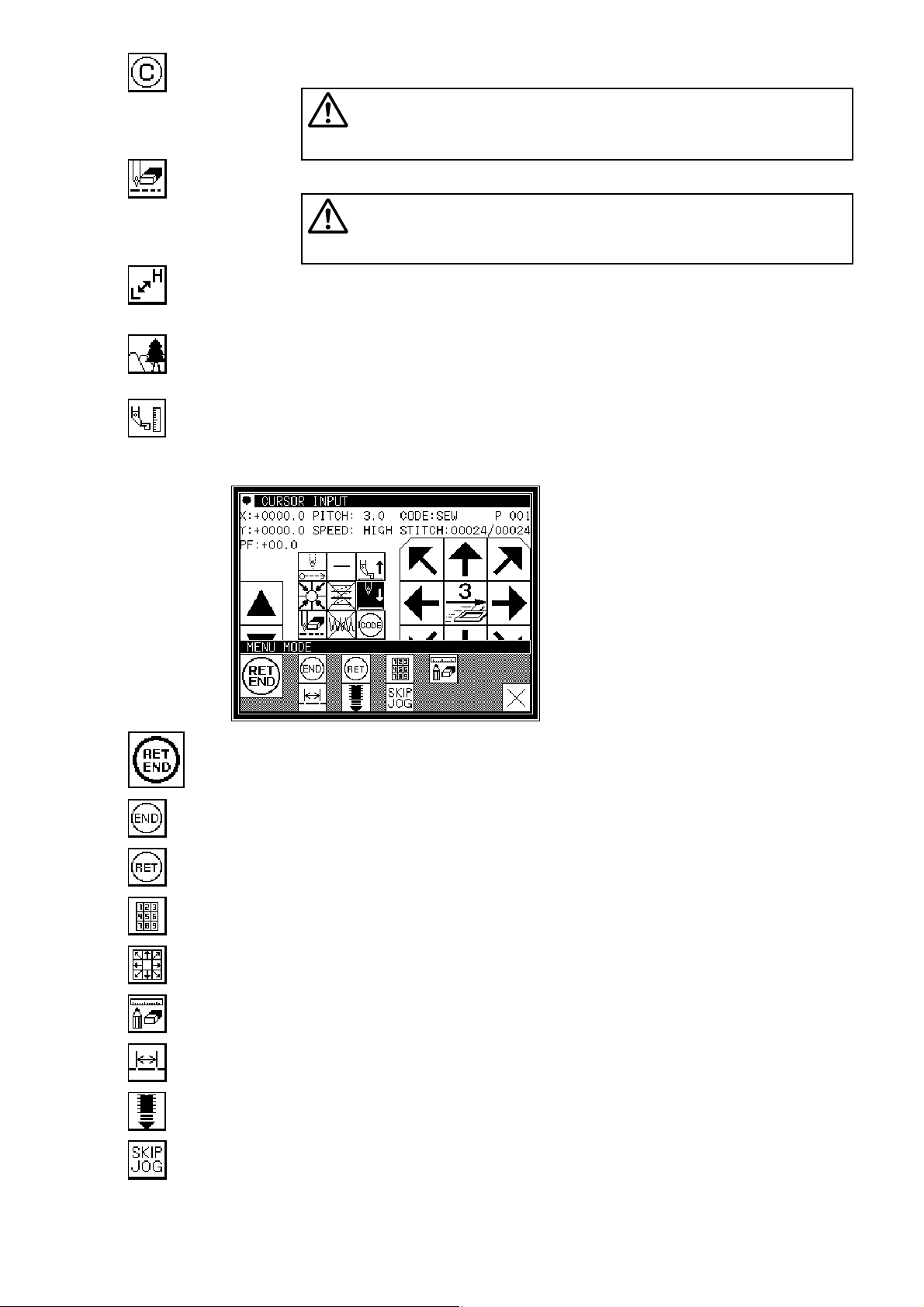
6. Explanations of basic icons
The basic icons used commonly on several screens are explained in this section.
… Executes home position return.
… Enter : determines the settings, etc.
… Returns to the previous screen.
… Exits the current mode.
… Cancel : undo the previous operation.
… Opens the menu window.
… Displays the previous/next list when lists are displayed (pattern data list, mode list, etc.)
… Turns skip jogging ON/OFF, and opens the operation setting screens.
[3] - 4
Page 14
7. Explanation of operations
(1)Stitching operations
[1] Reconfirm the stitching data before starting. Take special care to the set stitching speed.
[2] The stitching speed is determined according to the set speed and stitch length. The maximum stitching speed is
determined by the speed setting, and the stitch length limits the stitching speed.
[Caution] Do not change the sewing machine stitching speed during operation except in emergencies.
(Changing the speed can cause fault such as thread catching faults.)
[3] Set the material to be stitched, and turn the work holder switch ON. Next, when the start switch is turned ON, the
sewing machine will start rotating and stitching. Once started, stitching will continue even the operator's foot is
released from the start switch. When the stitching is completed, and the work holder returns to the home position,
the sewing machine will stop and the work holder will automatically rise.
Start stitching
Take down the work holder
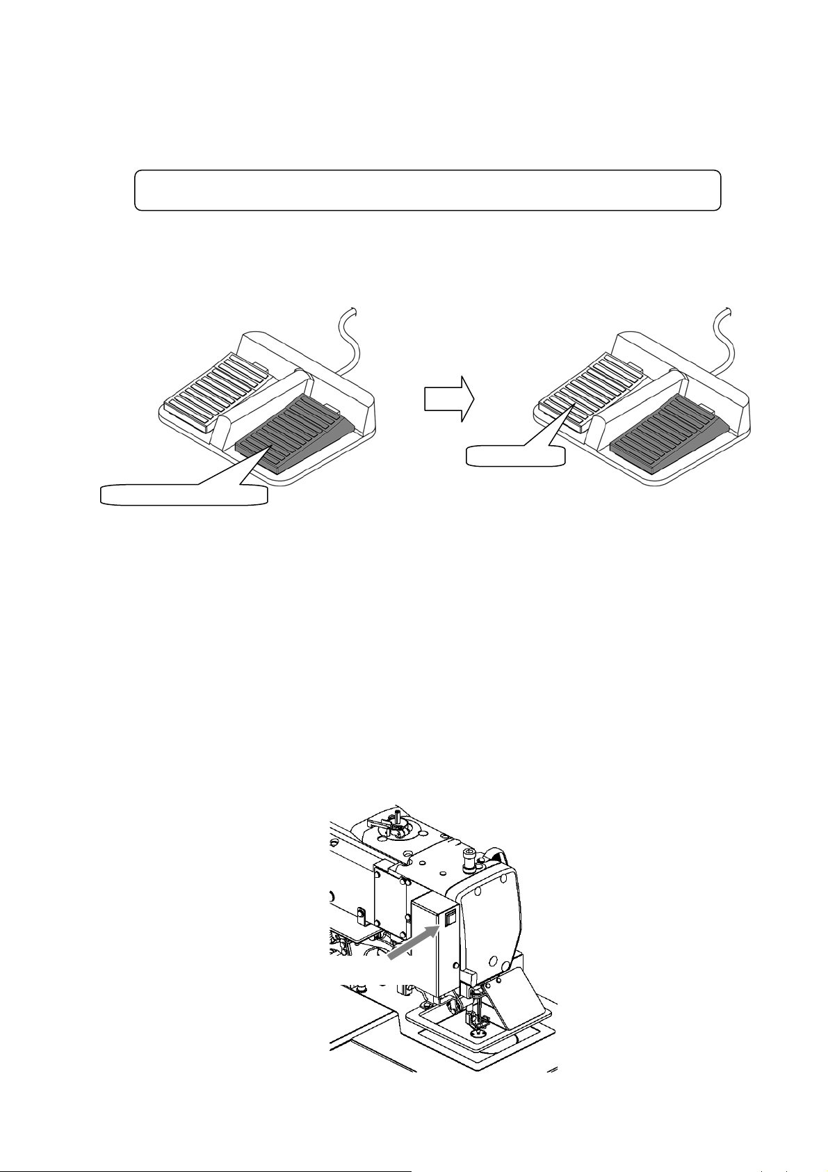
(2)Halting
To stop during the stitching, press the HALT switch (installed on sewing machine head; refer to following drawing).
The sewing machine will stop at the needle UP position. (Standard default setting.)
To cancel the halted state, press the HALT switch again. The following operations will be possible when the halted
state is canceled.
[1] Restart of stitching by pressing start switch. (gray pedal)
[2] Movement to stitching start position with forward jog/reverse jog icons.
[3] Lifting of work holder by pressing work holder switch. (black pedal)
[4] Change of stitching speed by setting stitching speed.
[5] Lifting/lowering of presser bar lifting.
[Note] The needle position during the halted state can be set with the program mode .
[Sewing machine head]
HALT switch
[3] - 5
Page 15
(3)Restitching methods
Restitching can be carried out using the previously explained halt function.
If the operation is halted due to needle thread breakage, etc., set the needle at the UP position, and then using the
forward jog/reverse jog icons, move to the position where the thread broke. Tie the needle thread, etc., and restart
stitching by pressing the start switch.
Caution
If the needle must be thread while the power is ON, do not turn
on the start switch while threading. Doing so initiates machine rotation, resulting in an
extremely dangerous situation. To ensure that the start switch is not turned on during
threading, take measures such as moving the start switch away from your feet.
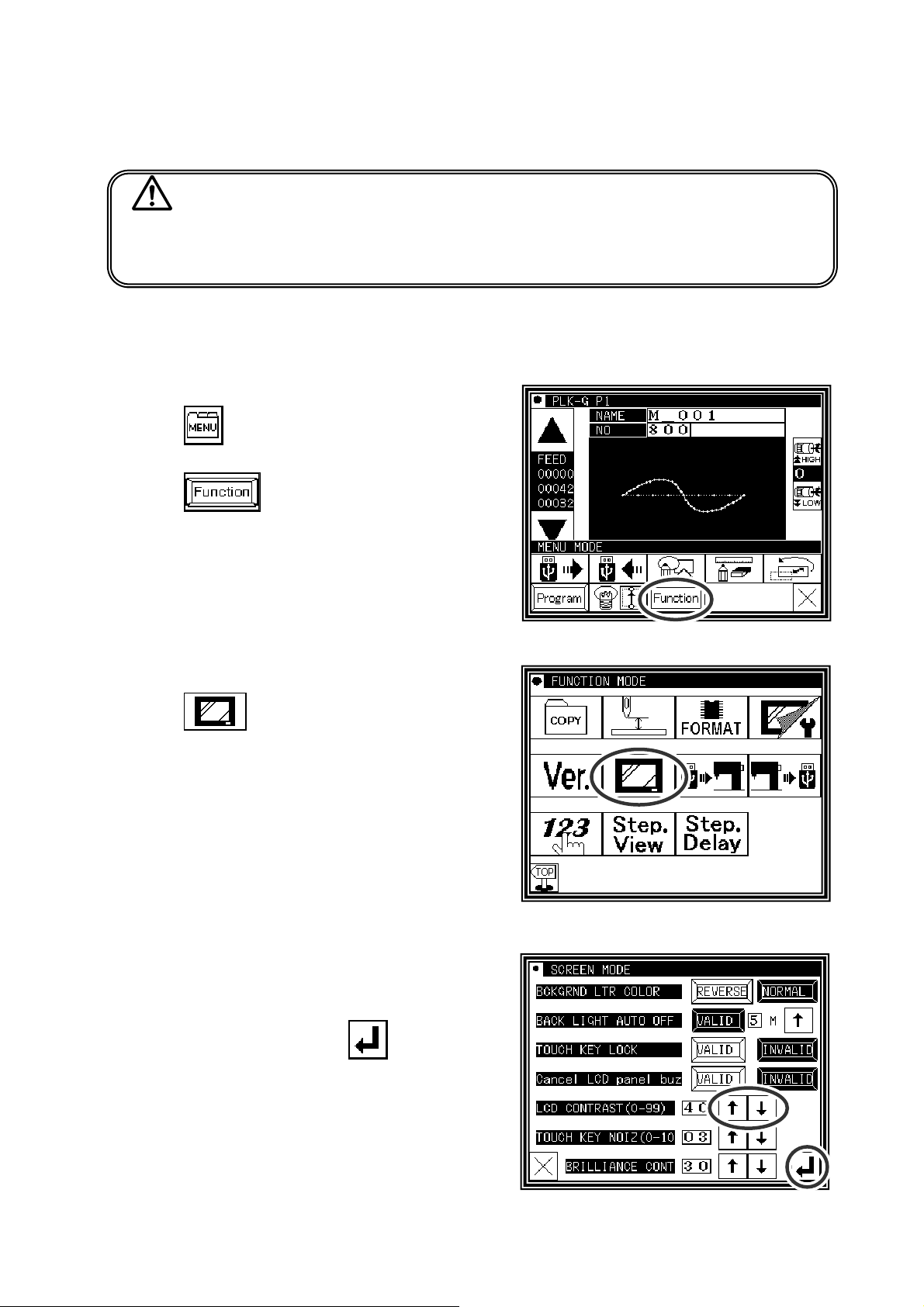
8.Adjusting the Liquid Crystal Contrast
(1)Entering the function mode
►Press
menu mode.
►Press
on the standard screen, and open the
(2)Entering the screen mode
►Press on the function mode menu, and open the
screen mode.
(3)Adjustment of LCD contrast
►Set the liquid crystal contrast value using the up and down
arrow icons.
►After setting the value, press the
apply the value.
►Back to Standard screen, then contrast setting is completed.
[Enter] icon to
[3] - 6
Page 16
[4] Sewing Data Compatibility
1.Number and type of Sewing Data
Number Type Explanation
100 ~ 999
(*1)
100 ~ 399 A data
400 ~ 499 BA data
600 ~ 799 B data
(*1) :Pattern data which made in G series can be registered up to 900 (No.100-999) but number of the
pattern is changed by a size of each pattern.
G data
This is data created with the PLK-G series.
(The maximum number of stitches is 20,000 stitches.)
This is data created with the PLK-A series
(old model).
This is data created with the PLK-B series and E series
(old model). (For embroidery data)
This is data created with the PLK-B series and E series
(old model).
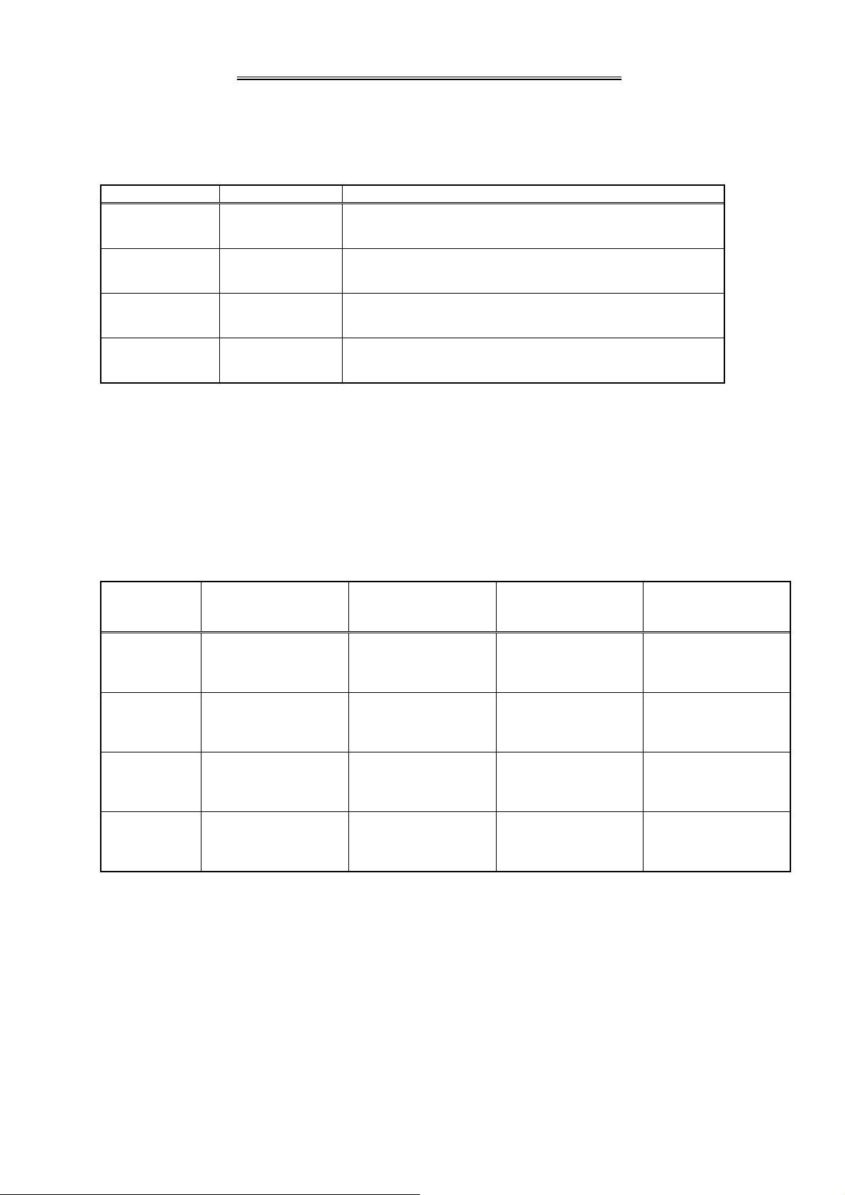
2.Sewing Data Compatibility
The following table shows the handling capabilities of the sewing machine (PLK-G series) with respect to
four types of sewing data.
Continuous input,
Type Reading Stitching
Modification and
Conversion
Writing
A data
BA data
B data
G data Available Available Available Available
(*1) : The sewing data can be read after converting to G data.
(*2) : It is written as G data.
Available
(*1)
Available
(*1)
Available
(*1)
Available Available
Available Available
Available Available
Available
(*2)
Available
(*2)
Available
(*2)
[4] - 1
Page 17
[5] Reading, writing and erasing data
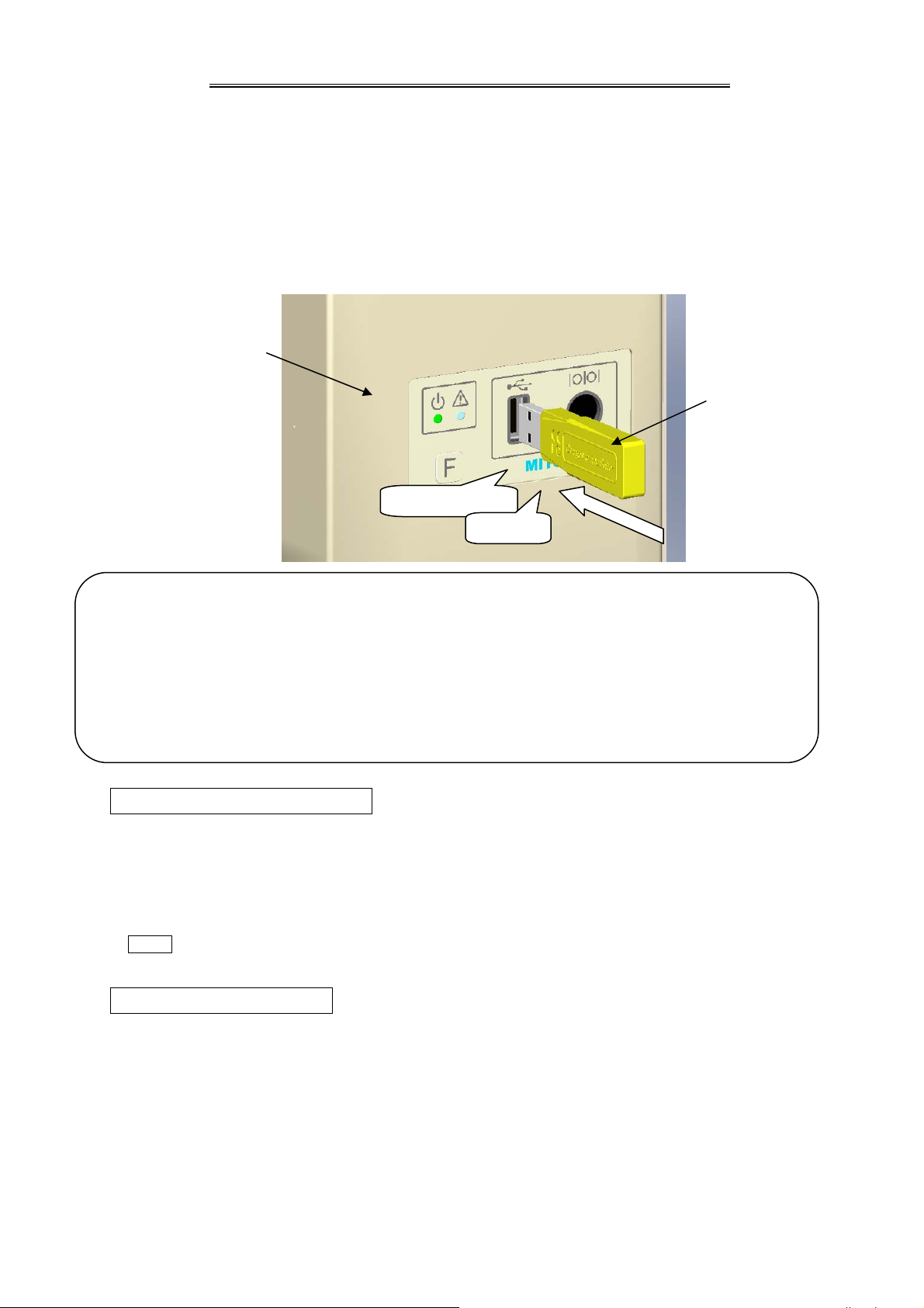
1. USB
To perform actions such as storing (reading/writing) sewing data on a device other than the internal memory
or reinstalling the system, a USB device is used. The device is connected to the USB connector on the front
side of the control box.
When using a USB device, be sure to fully insert the device into the USB connector. (Refer to the figure
below.)
Front panel
USB memory
straightforward
Certainly
[Caution]
■ Connect the USB device during use only. After use, remove and store the device in an appropriate
location. When USB device is not connected, insert protection cap to the USB connector.
(Protection cap must be inserted correctly according to the shape of the USB connector)
■ Sewing cannot be performed with the USB device inserted.
■ Do not insert the USB device during sewing.
■ Be careful that nothing bumps into the inserted USB device.
Conditions of Application
▪ USB1.1 or USB2.0 compatible USB memory and USB floppy disk drive (Note, however, formatting cannot
be performed with a floppy disk drive connected to the machine.)
▪ Required power supply: USB compatible, 500mA or less
Note The write-protector might not be able to recognized according to the kind of USB device.
Please make sure to release the write-protection before writing data to the USB memory.
Inapplicable Devices ■Never connect the following devices.
(Doing so causes malfunctions.)
▪ USB device requiring an external power supply (including Computer devices)
▪ USB hard disk drive, keyboard, mouse
▪ USB memory with fingerprint authentication function or with security function
▪ USB memory with hub function
▪ Media reader
▪ USB device without data storage function
[5] - 1
Page 18
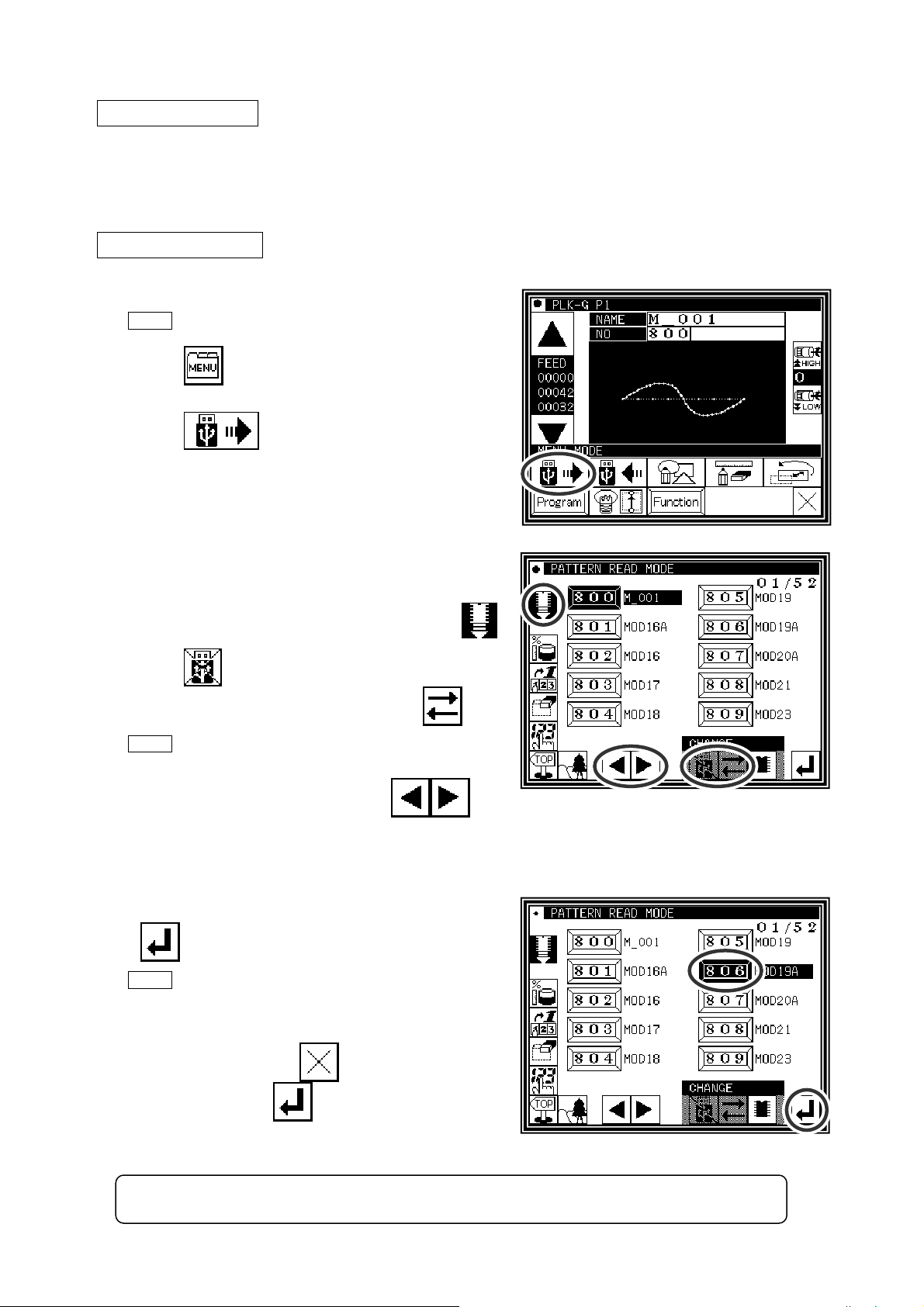
2.Reading
Operation points
·Select “Read mode” from the menu.
·Select the target (internal memory/USB memory).
·Select the data, and execute reading.
Operation details
(1)Selecting data read
Note Data reading excluding the start position cannot be
executed. Read pattern data after home returning.
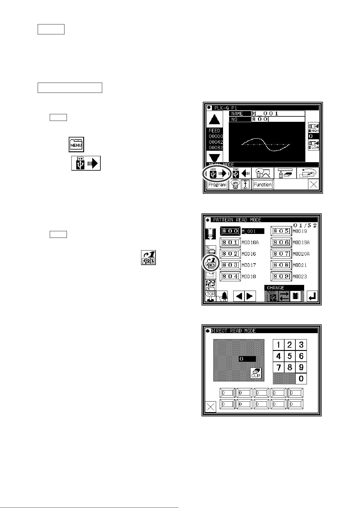
►Press
on the standard screen, and open the
menu mode.
►Press
.
(2)·Select the target (internal memory/USB memory).
►When the screen first opens, the mode to read from the
internal memory is selected.
(The mode display at the upper left of the screen is
►Press
(The mode can also be changed by pressing
Note If the USB memory is not inserted into the USB
connector, USB memory icon can not be selected.
►If there is a large amount of data, press
to change to reading from the USB memory.
)
to
)
change the screen.
(3)Selecting and setting the data
►Press the number of the data to be read, and then press
.
Note
►The read data will be displayed.
[ Caution ] When the target is the USB memory, do not remove the USB memory during reading.
When you read data from the USB memory and
select a data number that already exists in the
internal memory, a message confirming that you
overwrite the data appears. If you do not overwrite
the data, press the
data, press the
(Doing so may result in data damage.)
icon. If you overwrite the
icon.
[5] - 2
Page 19
Note When the pattern data number is already known, it is possible to read by specifying the
number directly by the following operations.
(Following operation is limited to reading from an internal memory. )
Reading [Direct reading mode]
Operation details
(1) Selects pattern data read button
Note Data reading excluding the start position cannot be
executed. Read pattern data after home returning.
►Press
►Press
, then menu screen is displayed.
.
(2)Selects direct pattern number selection
Note Direct pattern number selection is possible only to the
data stored into the internal memory.
►Press direct pattern number button
.
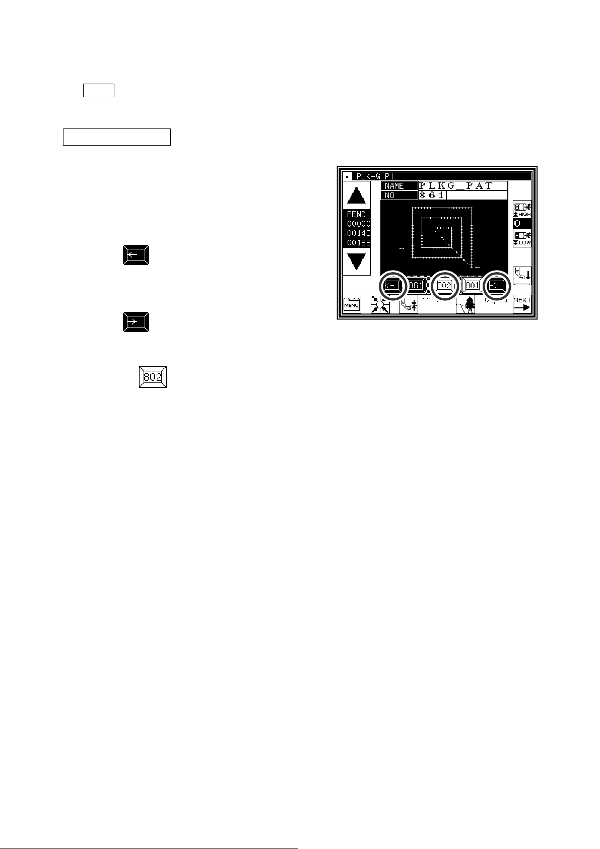
(3) Specifies pattern data number 1
(example.Case of reading number [861]. )
► Press number button [8].
► Then 10 of pattern datas which number start from 8 are
displayed.
[5] - 3
Page 20
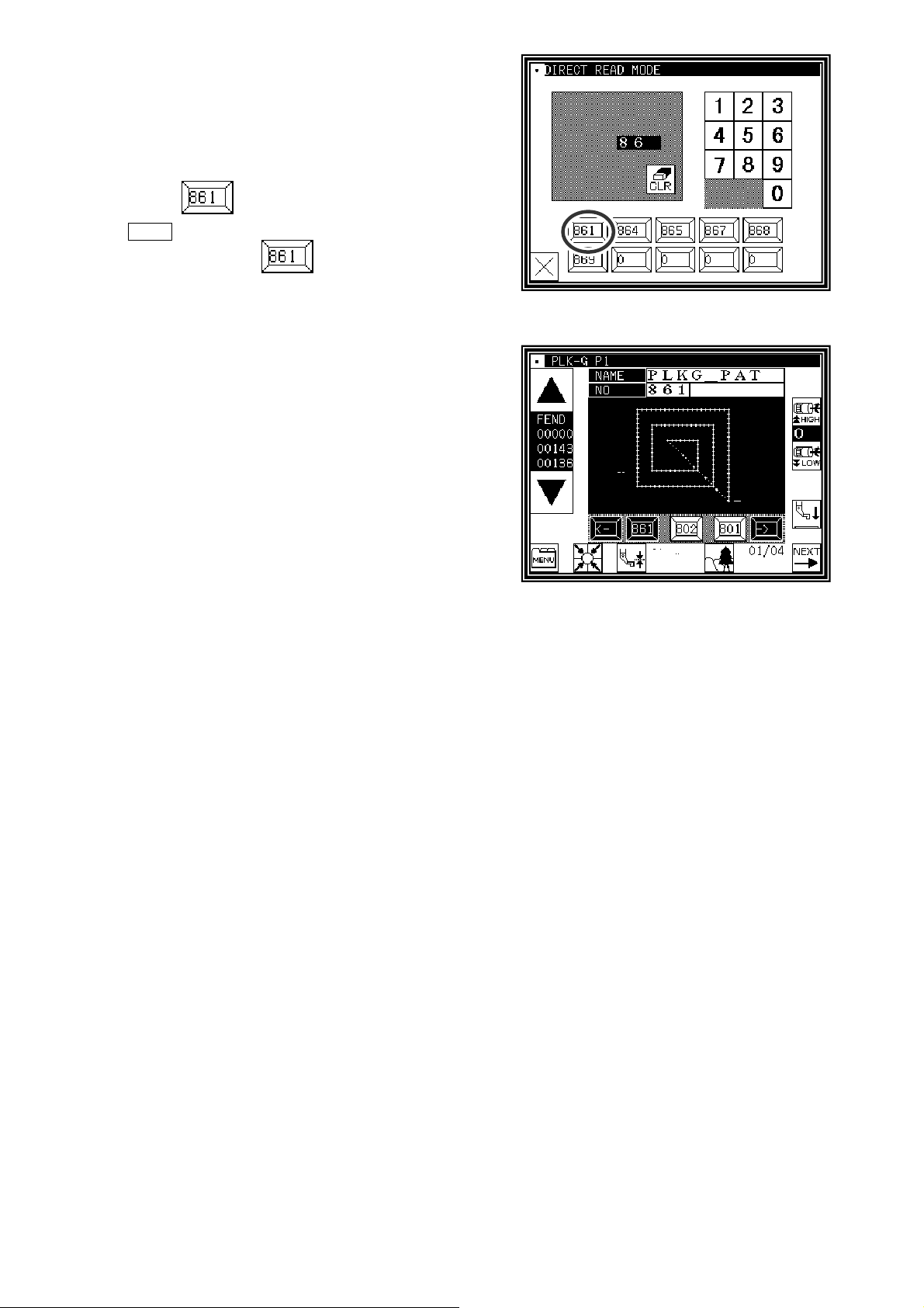
(4) Specifies pattern data number 2
►Next press number button [6].
► Then all pattern data which number starts from 86 is
displayed.
►At this time, desired pattern number [861] is displayed, then
press .
Note It is also available, if inputs 3 digits in the column as
[861] and push button.
(5)Data read complete
►Standard screen with the figure of pattern number [861] is
displayed.
[5] - 4
Page 21
3.Writing
Operation points
·Select “Write mode” from the menu.
·Select the target (internal memory/USB memory).
·Set the pattern name and number, and execute writing.
Operation details
(1)Selecting data write
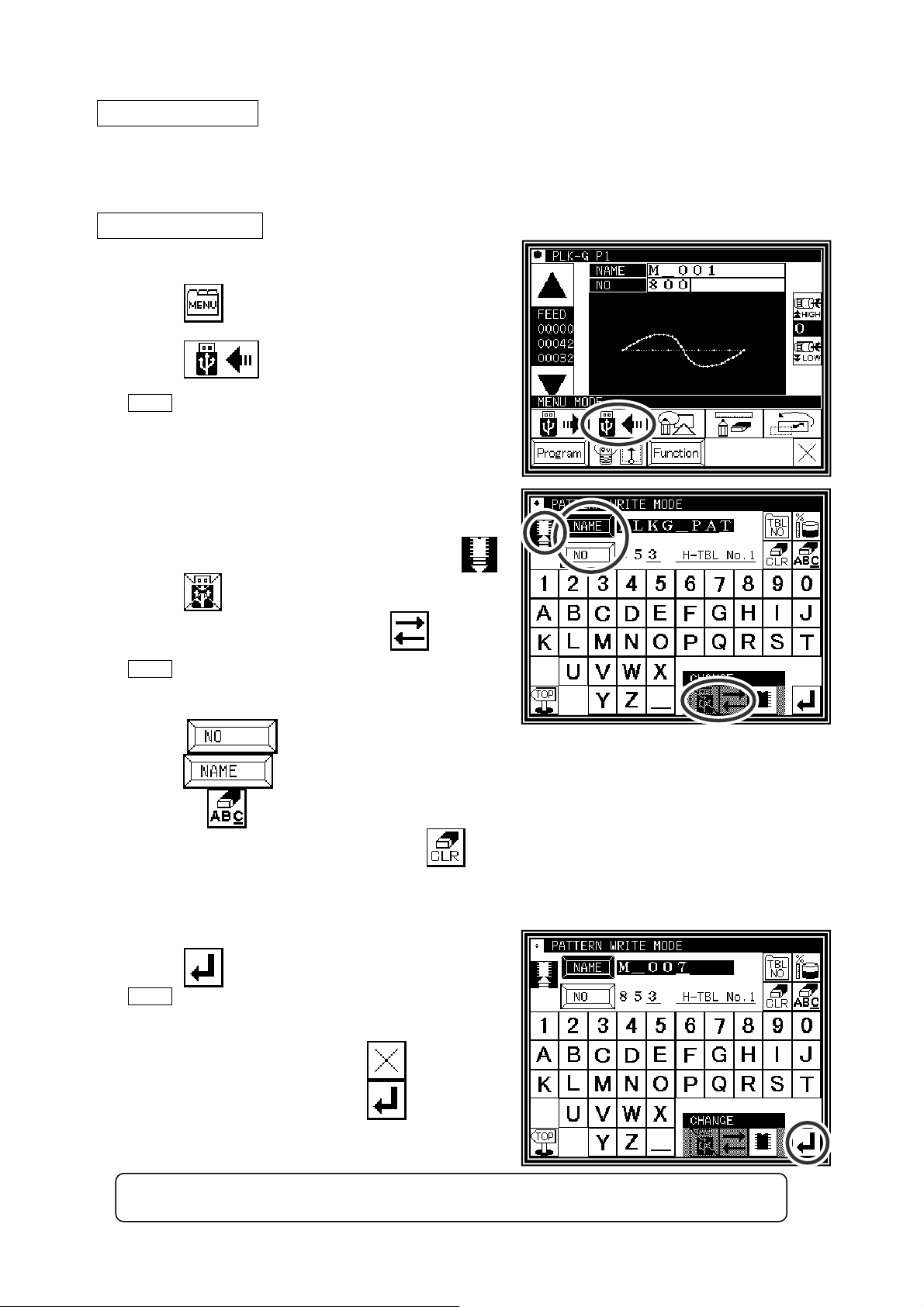
►Press
on the standard screen, and open the
menu mode.
►Press .
Note Data writing excluding the start position cannot be
executed. Write pattern data after home returning.
(2)Setting the pattern number and name
►When the screen first opens, the mode to write to the
internal memory is selected.
(The mode display at the upper left of the screen is
►Press to change to writing to the USB memory. (The
mode can also be changed by pressing
Note If the USB memory is not inserted into the USB
connector, USB memory icon can not be selected.
►Set the pattern number and name.
P
ress , and to change the name
)
)
ress
p
When the
the pattern number or name. If press the
(
The pattern name can have up to eight characters.
. Highlight the icon, and then change the setting.
icon is pressed, one of the alphanumeric characters from the right can be deleted from
icon, all character is deleted.
Specify the pattern number within the range of “800” to “999”.)
(3)Starting writing
►Press
Note
exists for the write target, a message confirming
that you overwrite the data appears. If you do not
overwrite the data, press the
overwrite the data, press the
►The standard screen will reappears.
[ Caution ] When the target is the USB memory, do not remove the USB memory during writing.
.
If you try to write a data number that already
icon. If you
icon.
(Doing so may result in data damage.)
[5] - 5
Page 22
4.Erasing
Operation points
·Select “Read mode” from the menu.
·Select the target (internal memory/USB memory).
·Select the data, and execute erasing.
Operation details
(1)Selecting data erase
►Press
on the standard screen, and open the
menu mode.
►Press
Note Data erasing excluding the start position cannot be
executed. Erase pattern data after home returning.
.
(2)Select the target (internal memory/USB memory).
►When the screen first opens, the mode to erase from the
internal memory is selected.
(The mode display at the upper left of the screen is
►Press
(The mode can also be changed by pressing
Note If the USB memory is not inserted into the USB
connector, USB memory icon can not be selected.
to change to erasing from the USB memory.
)
)
►If there is a large amount of data, press
change the screen.
(3)Selecting and erasing the data
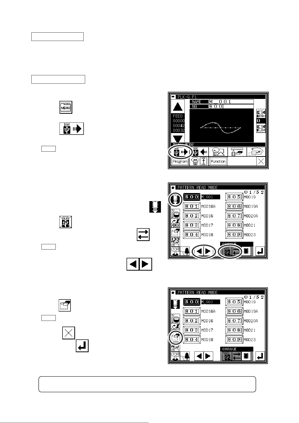
►Press (Select) the number of the data to be erased, and
press
Note
appears. If you cancel the erase operation, press
the
press the
erasing is in progress appears, and then the
Standard screen reappears.
[ Caution ] When the target is the USB memory, do not remove the USB memory during erasing.
.
A message confirming that you erase the data
icon. If you execute the erase operation,
icon. A message indicating that
(Doing so may result in data damage.)
to
[5] - 6
Page 23
5.Reading data with shortcut icons
(Reading from internal memory)
Memo Data can be read out with easy operations.
Operation details
(1)Reading data
►
Use the icon under the image area of the standard
screen for call-up operation.
(No. 802 is used as an example here.)
►
Press to sequentially display the No. icon for
the data written in the internal memory from left to
right.(*1)
►
Press to sequentially display the No. icon for
the data written in the internal memory from right to left.(*1)
►
Press the (No. icon). The data written in the internal memory will be called out. (The data having
the number indicated on the icon will be called out.)
(*1) 20 data recently used are stored.
[5] - 7
Page 24
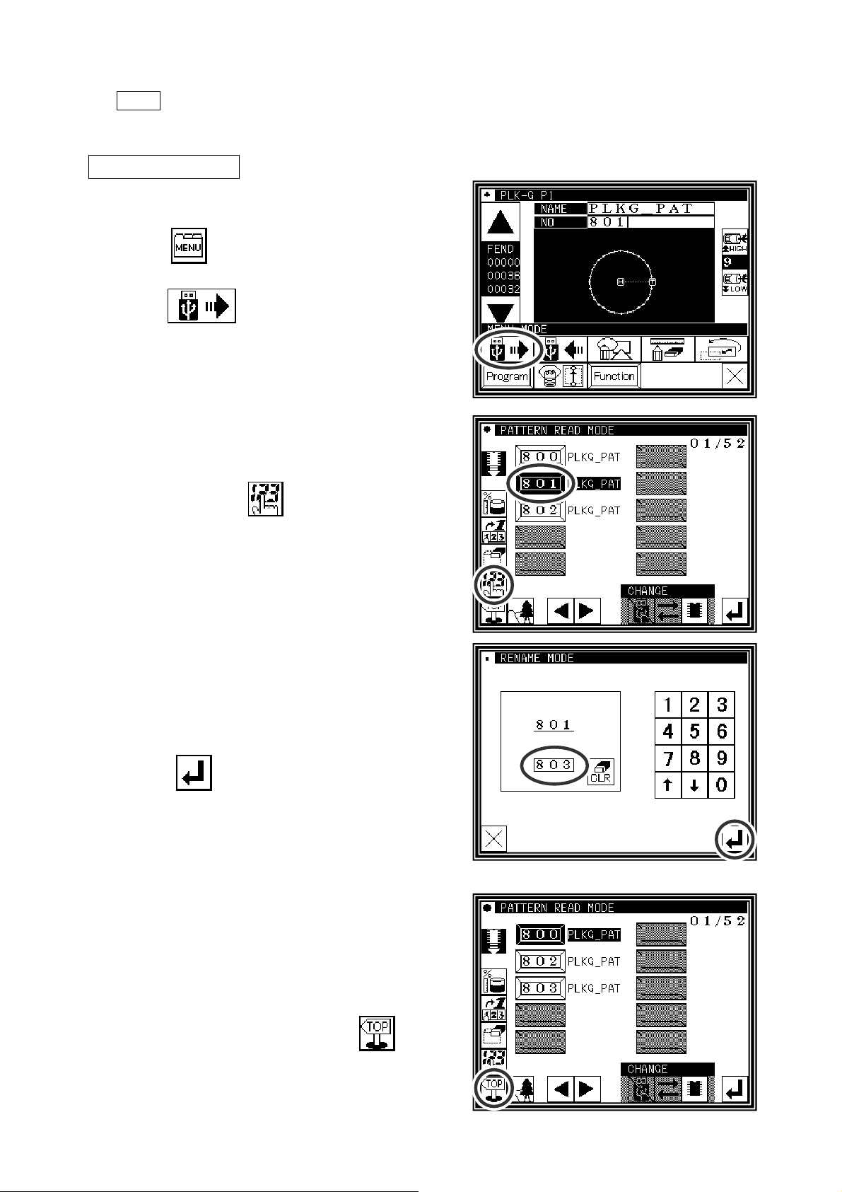
6. Rename the data number
Memo The number of the data that was saved in an internal memory can be changed.
Operation details
(1) Selecting data read
► Press
menu mode.
►Press
(2) Selecting the data
►
Selecting the number of the data that wants to
change and press
on the standard screen, and open the
.
.
(3) Specifies number
► Specifies the number that wants to change using the
numeric key.
►
Press after specifying.
(4) Completing change
► The number of “801” was changed to “803” in this example.
► To return to the standard screen, press
.
[5] - 8
Page 25
[6] Creating stitching data
1.Flow of data creation
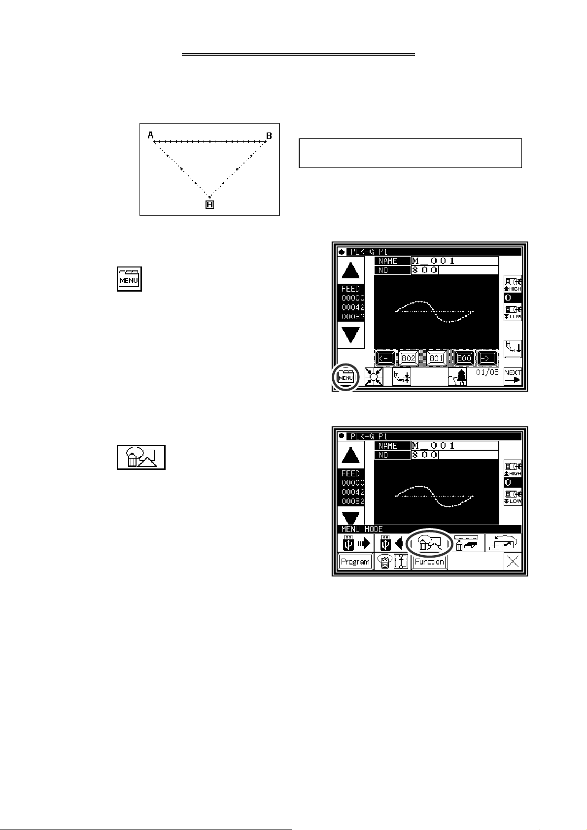
The flow of creating simple stitching data, as shown below, is explained in this section.
[Sample Fig.1]
(1)Start from the standard screen
The flow of operations for creating data and the
transition of screen displays are explained here.
►Press
.
(2)The menu mode will open.
►Press
.
[6] - 1
Page 26
(3)The “INPUT MODE” screen will open.
►If the data has not been input on the standard screen, the
and icons will not appear. To clear the input
data and input new data, press
To continuously input after the data already input, press
.
►Set the speed.
.
High speed Low speed
Medium-1 speed
Medium-2 speed
►Set the stitch length
Set in the range of 1 (0.1mm) to 200 (20.0mm) using the
►When completed setting the data, press .
to and , icons.
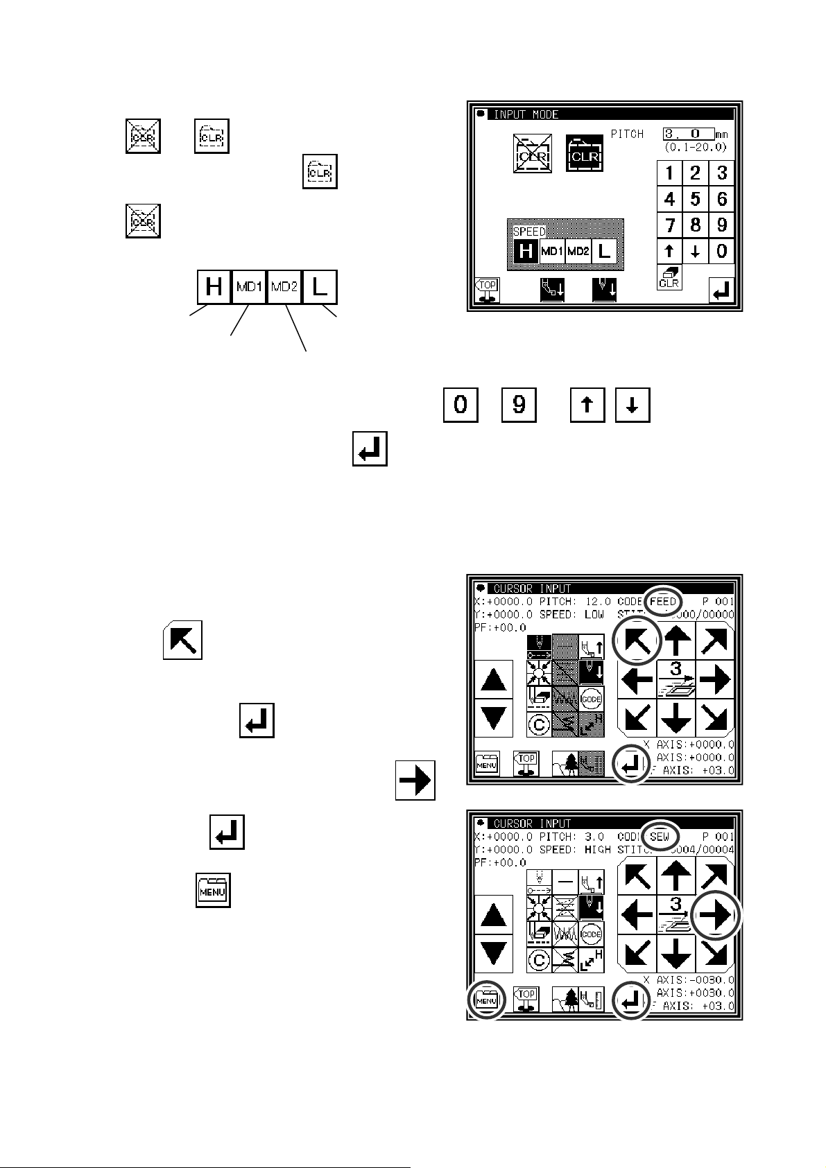
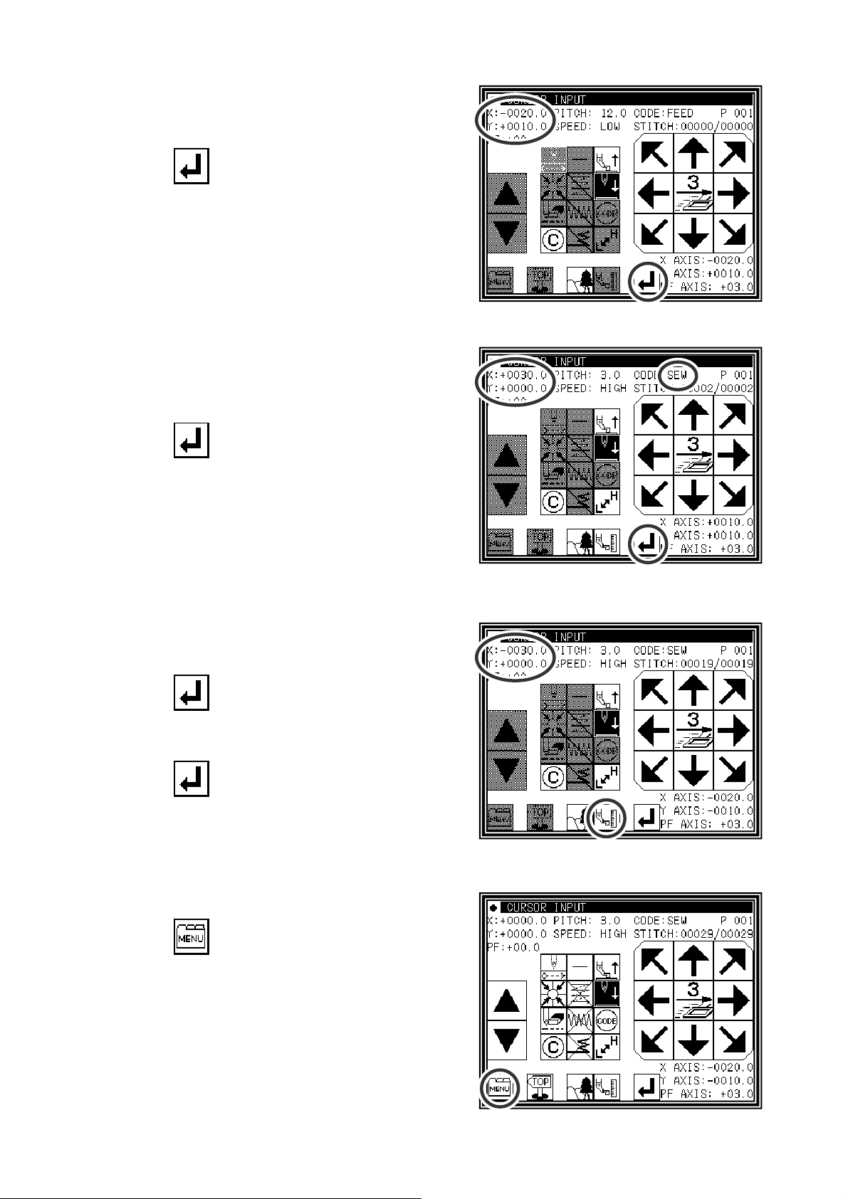
(4)The arrow input screen will open. (Input the sample Fig. 1 data.)
► When this screen is first opened, the code is set to FEED
(feed data).
Press
starting stitching. (Movement using the arrow mark icons
will change the X and Y position values displayed on the
screen.)
After moving, press
(Data on feed data to point A will be created.)
►Next, the code is set to SEW (sewing), so press
and move to the position (B point) for ending stitching. After
moving, press
on straight stitching to point B will be created.)
►Next, press
and move to the position (A point) for
, and set the current position.
, and set the current position. (Data
.
[6] - 2
Page 27
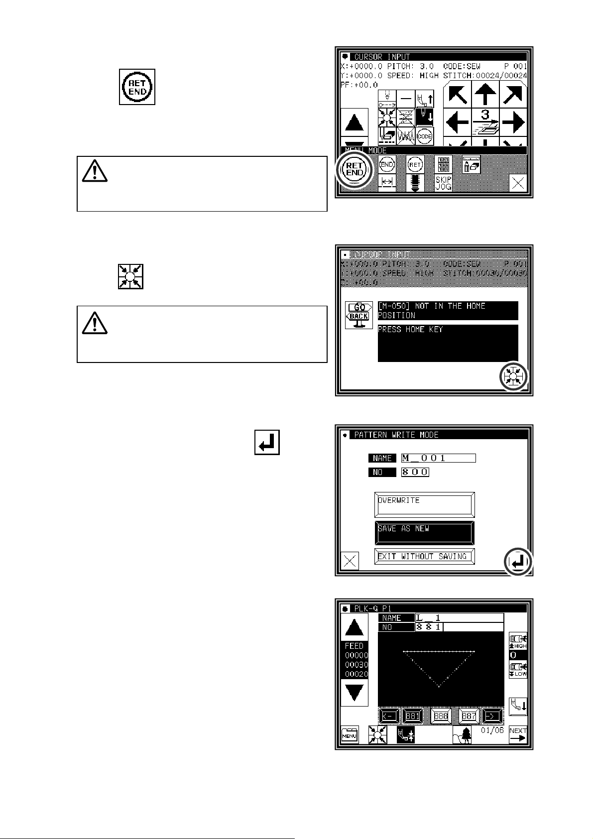
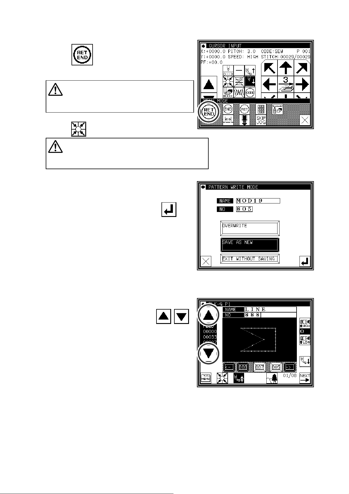
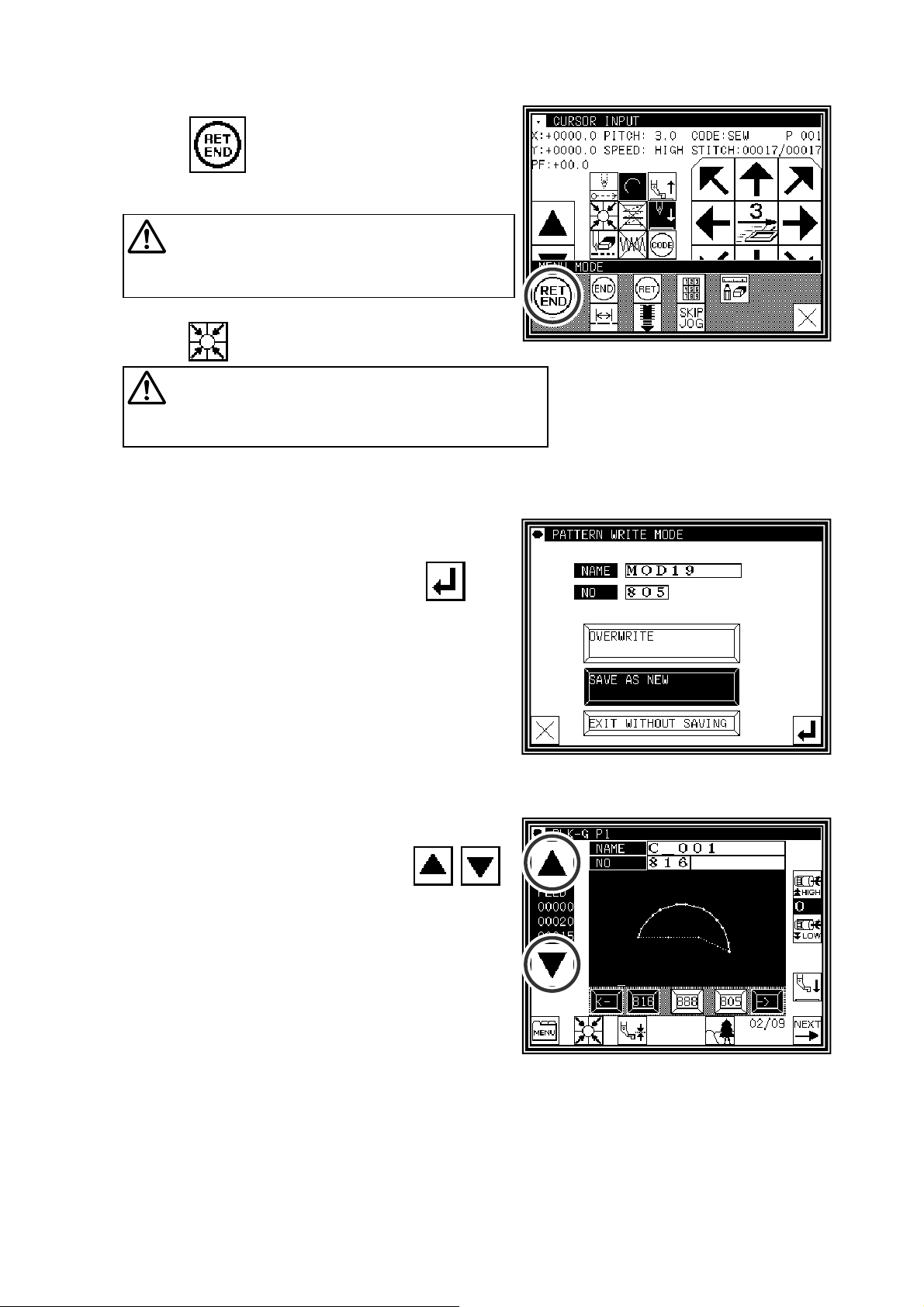
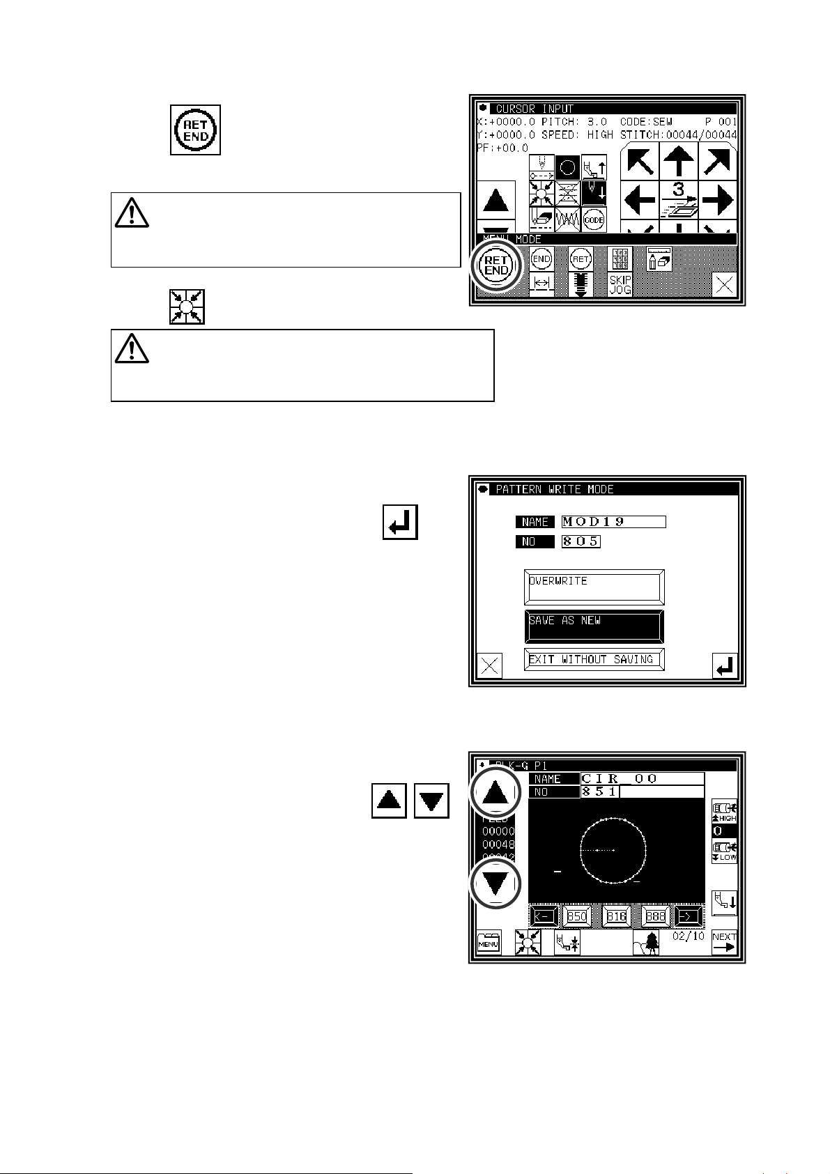
(5)The “INPUT MODE” menu will open.
►When
the home position, and inputting of data will be
completed.(Data on feed data to the home position and the
end code will be created.)
Caution
return to the home position.
Take care when the needle is lowered, etc.
is pressed, the work holder will return to
The work holder will automatically
(6)A prompt for home position return will appear.
►Press
Caution
position. If the needle is not at the UP position, it may
lower once and then return to the UP position.
The needle will rise to the UP
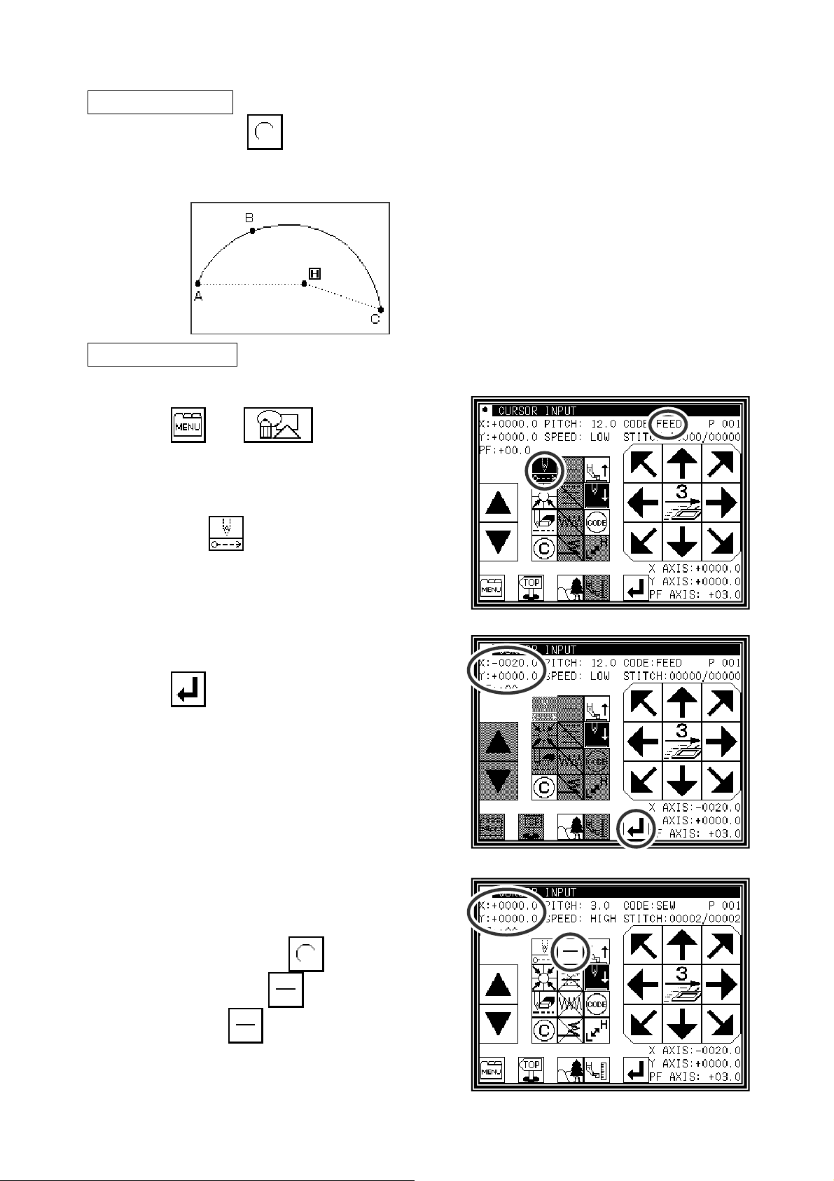
(7)Select a saving method.
►After selecting the saving method, press icon.
(Refer to “[5] Reading, writing and erasing data”)
(8)The Standard screen will open.
►Return to the Standard screen and confirm the input data.
►This completes the input.
[6] - 3
Page 28
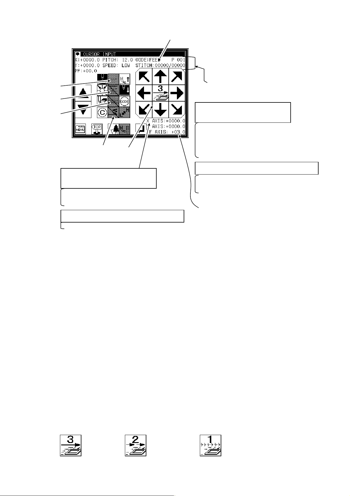
2.Description of arrow input screen
[5]
The arrow input screen is described below.
[1]
[2]
[3]
When the needle is at the final stitch
(current needle position value
= total number of stitches)
Arrow mark icons will appear and data entry will be
possible. To enter the position value, move the
work holder using the arrow mark icons.
During operation in the jog mode
(current needle position < total number of stitches)
The image currently creating will be displayed.
[4]
[6]
The current status will be displayed.
"STITCH": Shows the "current needle position
When the needle is at the final stitch
(current needle position value
= total number of stitches)
"X, Y": Shows the position values entered with the
"Stitch length", "speed", "code"
"P": Shows the number of points entered for an arc,
During operation in the jog mode
(current needle position < total number of stitches)
"X, Y", "Stitch length", "speed", "code"
Displays XY current stitch position
as an absolute value based on the
home position.
value/total number of stitches".
arrow mark icons.
: Shows the currently-set values.
curve, etc.
: Shows the needle data of the specified
position.
[1]”Data entry method setting icon”
The basic data entry method currently set will appear. (Point, straight line, broken line, circle, arc,
curve) Press this icon to display the data entry method setting screen.
[2]”Multi-stitching, reverse multi-stitching, offset data setting icon”
The multi-stitching, reverse multi-stitching, and offset data currently set will appear. (Not set,
multi-stitching (feed data mode), reverse multi-stitching (feed data mode), multi-stitching (sewing
mode), reverse multi-stitching (sewing mode), offset) Press this icon to display the multi-stitching,
reverse multi-stitching, offset data setting screen. Using this screen, you can set detailed data.
[3]”Zigzag setting icon”
The zigzag currently set will be displayed (zigzag or non-zigzag). Press this icon to display the
detailed zigzag data setting screen. Using this screen, you can set the detailed zigzag data.
[4]”Back tack setting icon”
The back tack currently set will appear. (No back tacking, start/end back tacking, overlap back
tacking) Press this icon to display the detailed back tacking data setting screen. Using this screen,
you can set detailed back tacking data.
[5]”Kind of code display”
FEED -----------FEND -----------SEW ------------P ---------------I ----------------O ---------------Z ---------------B ----------------
(Others, the various code data is displayed while JOG is operating.)
[6] [Clamp speed swich icon]
Feed
Feed end cord (Displayed while JOG is operating)
Basic input (Straight line, Arc, Circle, Curve, Broken line, Point)
Multiple sewing
Reverse multiple sewing
Offset sewing
Zigzag sewing
Back tacking sewing
Normal : A little slow : Slower
( Icon is changed whenever icon is pressed for a long period.)
[6] - 4
Page 29
“Cancel”: Cancels the last operation, and returns to the previous data entry point.
(
,
g
Caution The work holder will move. If the needle is lowered, be careful
not to get injured.
“Delete last point”: Deletes the last determined point, and returns to the previous data entry point.
“
Change sewing speed”: Each time you press this icon, the set speed will be changed in the order
The image display screen will be displayed.
The screen of setting material step will be displayed. (Refer to page [8]-2)
3.Description of menu
Caution The work holder will move. If the needle is lowered, be careful
not to get injured.
of “HIGH → LOW → MD2 → MD1 → HIGH.”
The data on feed data from the current position to the home position and the end code will
be created
The end code will be created, and the system will exit from the input mode.
and the system will exit from the input mode.
The data on feed data from the current position to the home position will be created.
The screen is switched to the data creation screen that enables direct entry of numeric values.
The screen is switched to the input screen that enables data entry using the arrow mark
icons
the arrow mark icons move the work holder).
You can enter the modification mode.
The stitch length change screen will appear.
When inputting data, the stitching data saved in the internal memory is added to the end of
the data bein
input.
The skip jog setting screen will appear. (The details are explained on the next page.)
[6] - 5
Page 30
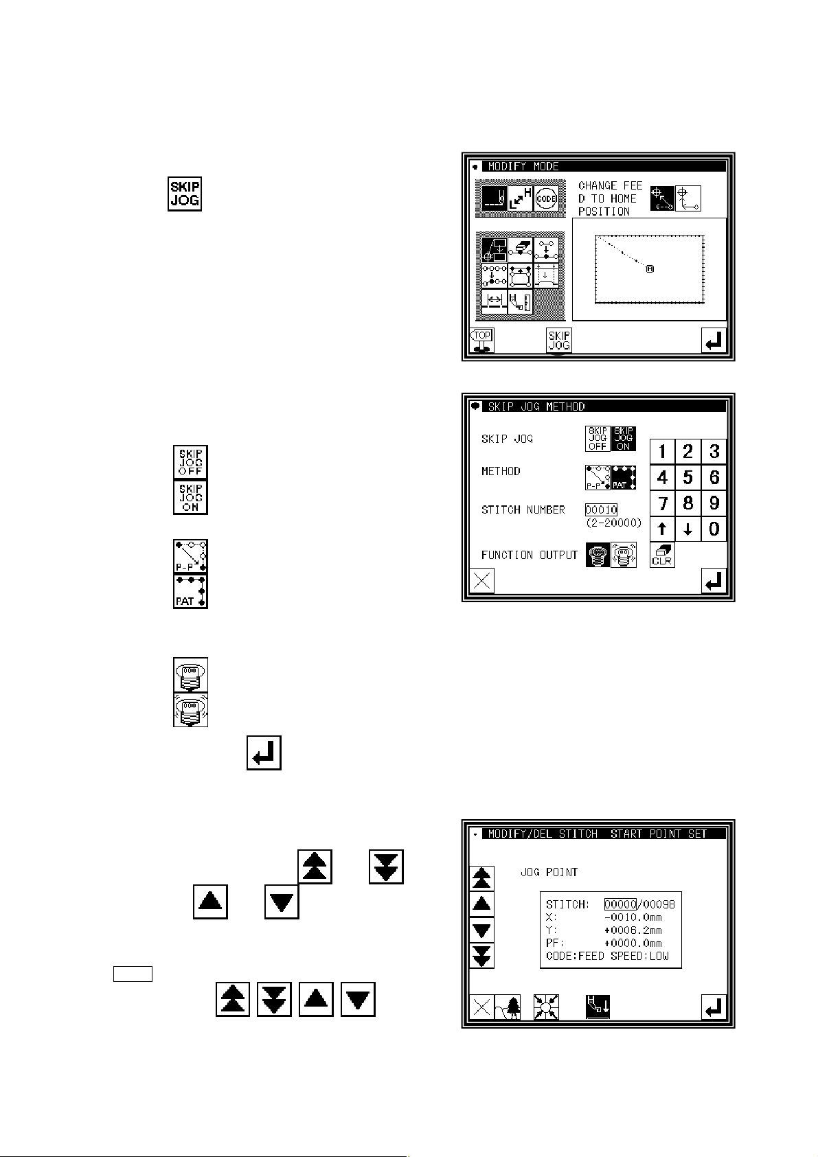
4.Skip jogging
Skip jogging allows movement to the target needle position at a faster speed than normal jogging. Skip
jogging can be used in the input, modification and conversion modes.
(1)Turning skip jogging ON/OFF, and displaying the setting screen
►
Press found on the input screen menu, the
modification mode and conversion mode.
(The explanations are made with the Modification
Mode screen.)
(2)Setting skip jogging
►
Determine whether to use (ON) or not use (OFF)
skip jogging.
►
Determine the movement method.
: Do not use. (OFF)
: Use. (ON)
: Move linearly.
: Move along a path.
►
Using the numeric keypad, set the number of movement stitches.
►
Determine the function output method.
: The output signal is invalid.
: The output signal is valid.
►
After setting, press
.
(3)Skip jog operations
►
Skip jogging will start when and are
pressed. (
.
icons
Note
Skip jogging will stop
if one of is pressed.
and are the normal jogging
[6] - 6
Page 31

[7] Methods of creating sewing data
Caution
icon is pressed.
Note that the needle will rise to the UP position when the "Home position Return"
(If the needle is not at the UP position, it may lower once and then return to
the UP position.) By removing the presser bar lifting from sewing machine, data can be input
safety and accurately.
Basic Inputs
Function icon Explanation
Linear
([7]-1)
Arc
([7]-4)
Circle
([7]-8)
Curve
([7]-11)
Broken line
([7]-15)
Point
([7]-18)
Code
([7]-20)
2-point input: A linear line is created between the current position (already input)
and the newly input point.
3-point input: An arc, passing through the current position (already input) and two
newly input points, is created.
3-point input: A circle, passing through the current position (already input) and two
newly input points, is created.
A curve passing through the current position (already input) and the input point
(up to 300 points possible) is created.
A broken line connecting the current position (already input) and the input point
(up to 300 points possible) is created.
The point can be input one stitch at a time.
* The distance between the points must be within 20mm.
The code by which various controls are done can be input.
1.Linear input
Operation points
▪ Designate linear input(
▪ Input two points (A linear line is created between the current position (already input) and the newly
input point.)
[Example] The following type of sewing data will be created.
Operation details
(1)Inputting feed data to A point
►
Press and on the Standard
screen. After making the various settings on the Data
Setting Input screen, the Arrow Input screen will open.
(Refer to Page[6]-2)
)
►
Check that the code is set to FEED. If different code
is set, press
►
Press the arrow icons and move to the A point.
(Feed data to A point.)
and set the code to FEED.
[7] - 1
Page 32
(2)Setting feed data to A point
►
The movement amount can be confirmed.
[Example] X: -20.0, Y: +10.0
►
Press to set the data.
(Data on feed data to point A will be created.)
►
The movement amount will be cleared.
X:+0.0,Y:+0.0
►
The code will change to "SEW".
(3)Inputting stitching to B point
►
Press the arrow icons and move to the B point.
►
Press to set the data.
(
Data on straight stitching to point B will be created.)
(4)Inputting stitching from C point to D point
►
Press the arrow icons and move to the C point.
►
Press to set the data.
(
Data on straight stitching to point C will be created.)
►
Press the arrow icons and move to the D point.
►
Press to set the data.
(
Data on straight stitching to point D will be created.)
(5)Setting stitching to D point
►
Press
.
[7] - 2
Page 33
(6)Inputting the return/end code
►
Press .
(
Data on feed data to the home position and the end
code will be created.)
Caution
The work holder will
automatically return to the home position. Take
care when the needle is lowered, etc.
►
A prompt for home position return will appear.
Press
Caution
.
The needle will rise to the UP position.
If the needle is not at the UP position, it may lower
once and then return to the UP position.
(7)Select a saving method.
►After selecting the saving method, press icon.
(R
efer to section [5]Reading, writing and erasing data.)
►Return to the standard screen.
(8)Confirming the data
►
Confirm the data. Press the jog icons ( )
so the sewing machine movement can be confirmed.
(Even if the data input has not been completed, if the
data input last has been set, the movement can be
confirmed in the same manner.)
►
If the data must be modified, refer to section [11]
Modification mode Modifying the stitching data.
[7] - 3
Page 34
2.Arc input
Operation points
▪ Designate arc input ( )
▪ Input three points (An arc, passing through the current position (already input) and two newly input
points, is created.)
[Example] The following type of sewing data will be created.
Operation details
(1)Inputting feed data to A point
►
Press and on the Standard
screen. After making the various settings on the Data
Setting Input screen, the Arrow Input screen will open.
(Refer to Page[6]-2)
►
Check that the code is set to FEED. If different code
is set, press
►
Press the arrow icons and move to the A point.
(Feed data to A point.)
and set the code to FEED.
(2)Setting feed data to A point
►
The movement amount can be confirmed.
►
Press to set the data. (Data on feed data to
point A will be created.)
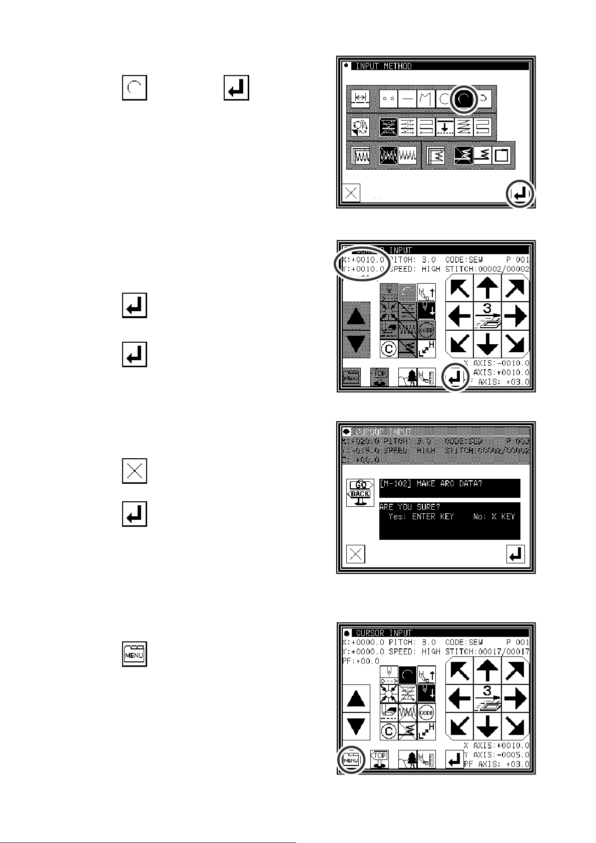
(3)Changing the input method
►
The movement amount will be cleared.
►
The code will change to "SEW".
►
If the stitching type is not "ARC
INPUT", (if the type is
INPUT"), press
and change the type.
"LINEAR
(The currently set stitching type will be displayed on
the icon.)
[7] - 4
Page 35
(4)Designating arc input
►
Press and then press .
►
The system will return to the arrow input screen.
(5)Setting B point and C point
►
Press the arrow mark icon to move to point B.
►
The movement amount can be confirmed.
►
Press to determine point B.
►
Press the arrow mark icon to move to point C.
►
Press and set the arc input.
(6)Creating the arc input data
►
The confirmation message "Create arc" will appear.
►
Press to return to the point C data entry
screen.
►
Press and start creation of the arc input data.
(The arc will be created.)
►
A message indicating that the data is being created
will appear.
(7)Completing creation of the arc input data
►
Press .
[7] - 5
Page 36
(8)Inputting the return/end code
►
Press .
(
Data on feed data to the home position and the end
code will be created.)
Caution
The work holder will automatically
return to the home position. Take care when the
needle is lowered, etc.
►
A prompt for home position return will appear.
Press
Caution
.
The needle will rise to the UP position.
If the needle is not at the UP position, it may lower
once and then return to the UP position.
(9)Select a saving method.
►
After selecting the saving method, press icon.
(R
efer to section [5]Reading, writing and erasing data.)
►Return to the standard screen.
(10)Confirming the data
►
Confirm the data. Press the jog icons ( )
so the sewing machine movement can be confirmed.
(Even if the data input has not been completed, if the
data input last has been set, the movement can be
confirmed in the same manner.)
►
If the data must be modified, refer to section [11]
Modification mode Modifying the stitching data.
[7] - 6
Page 37
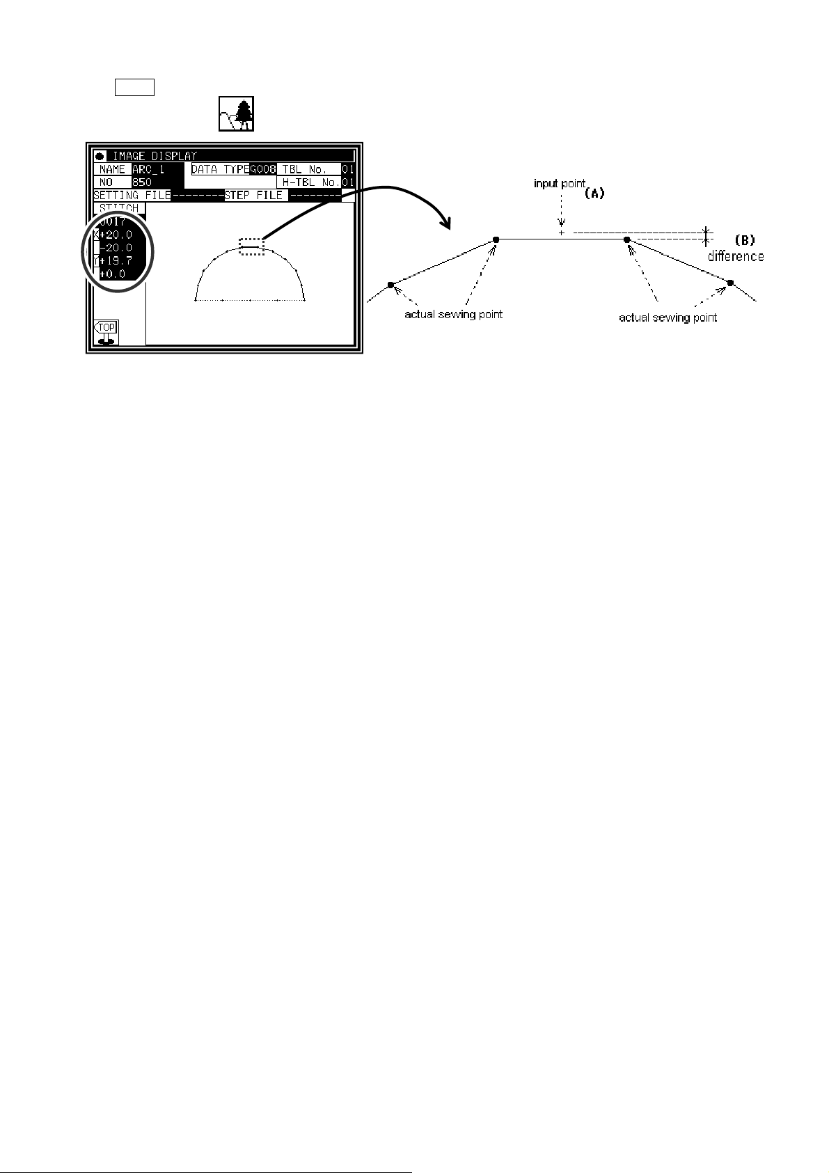
Memo The size display of the pattern data is explained when "The arc" or "The Circle" is made and the
image display is pushed from a standard screen, the image display screen is opened.
For instance, when made the 20mm half circle data but the size display is not [20.0] Y axially, is [19.9] it
like the above figure.
The reason for this is that the displayed value is calculated with an actual sewing point. Tries to make the
circle or the circular arc which passes input point as shown in the figure below, the data is made
according to the specified stitch length, it is not match that sewing point and input point (A). There is
difference (B) of the figure below because the value is calculated with the sewing point.
[7] - 7
Page 38
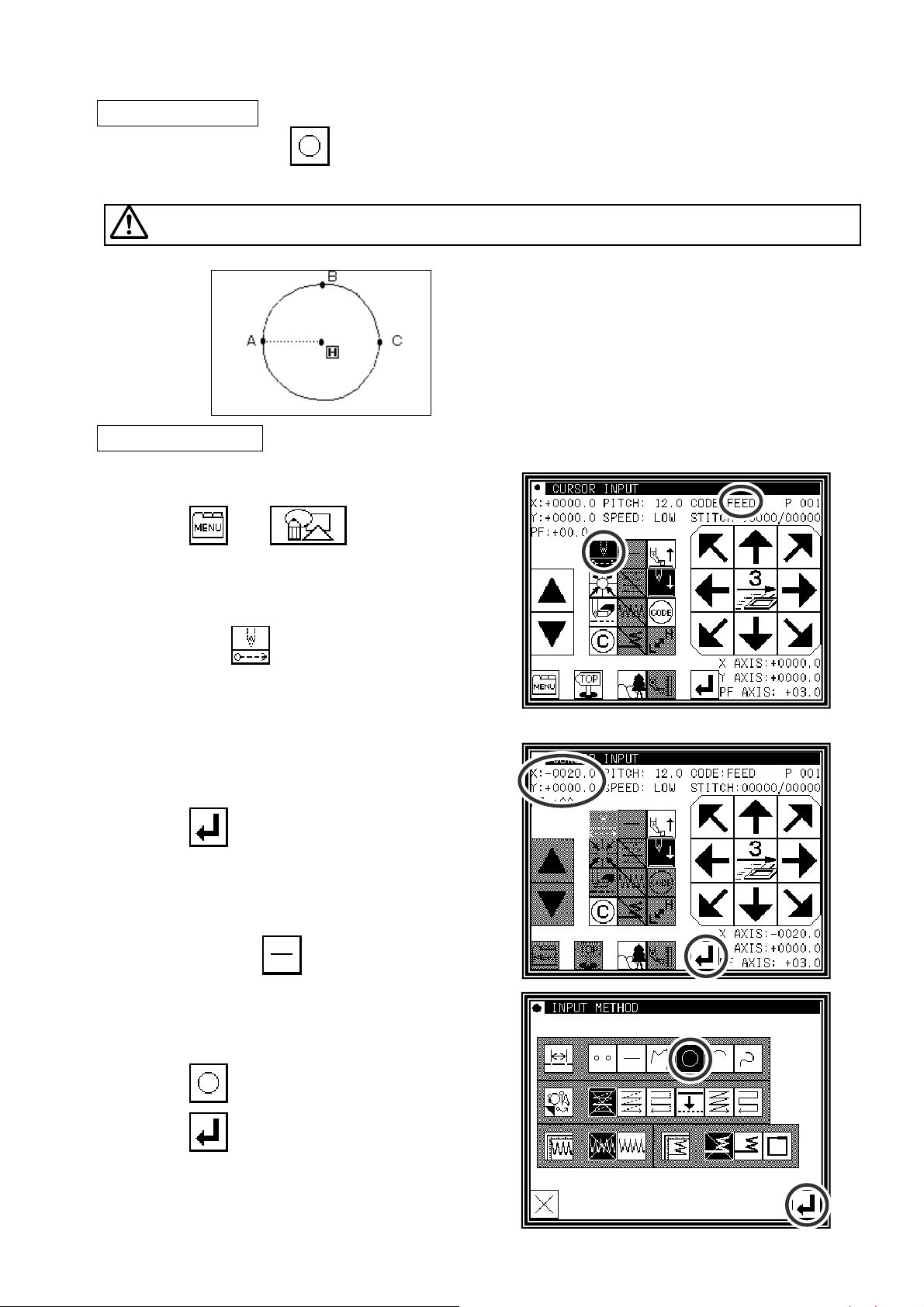
3.Circle input
Operation points
▪ Designate circle input ( )
▪ Input three points (A circle, passing through the current position (already input) and two newly input
points, is created.)
Caution
Note that the work holder will go back to the circle start position after the data is created.
[Example] The following type of sewing data will be created.
Operation details
(1)Inputting feed data to A point
►
Press and on the Standard
screen. After making the various settings on the Data
Setting Input screen, the Arrow Input screen will open.
(Refer to Page[6]-2)
►
Check that the code is set to FEED. If different code
is set, press
and set the code to FEED.
►
Press the arrow icons and move to the A point.
(Feed data to A point.)
(2)Setting feed data to A point
►
The movement amount can be confirmed.
►
Press to set the data.
(Data on feed data to point A will be created.)
►
To change the stitching type to "Circle input", press
the input method setting icon.
(In this case, the
icon.)
(3)Designating circle input
►
Press .
►
Press and set the data.
►
The system will return to the arrow input screen.
[7] - 8
Page 39
(4)Setting B point and C point
►
Using the arrow icons, move to the B point.
►
Press to determine point B.
►
The Arrow Input screen will reappear, so press the
arrow icons and move to the C point.
►
Press to determine point C.
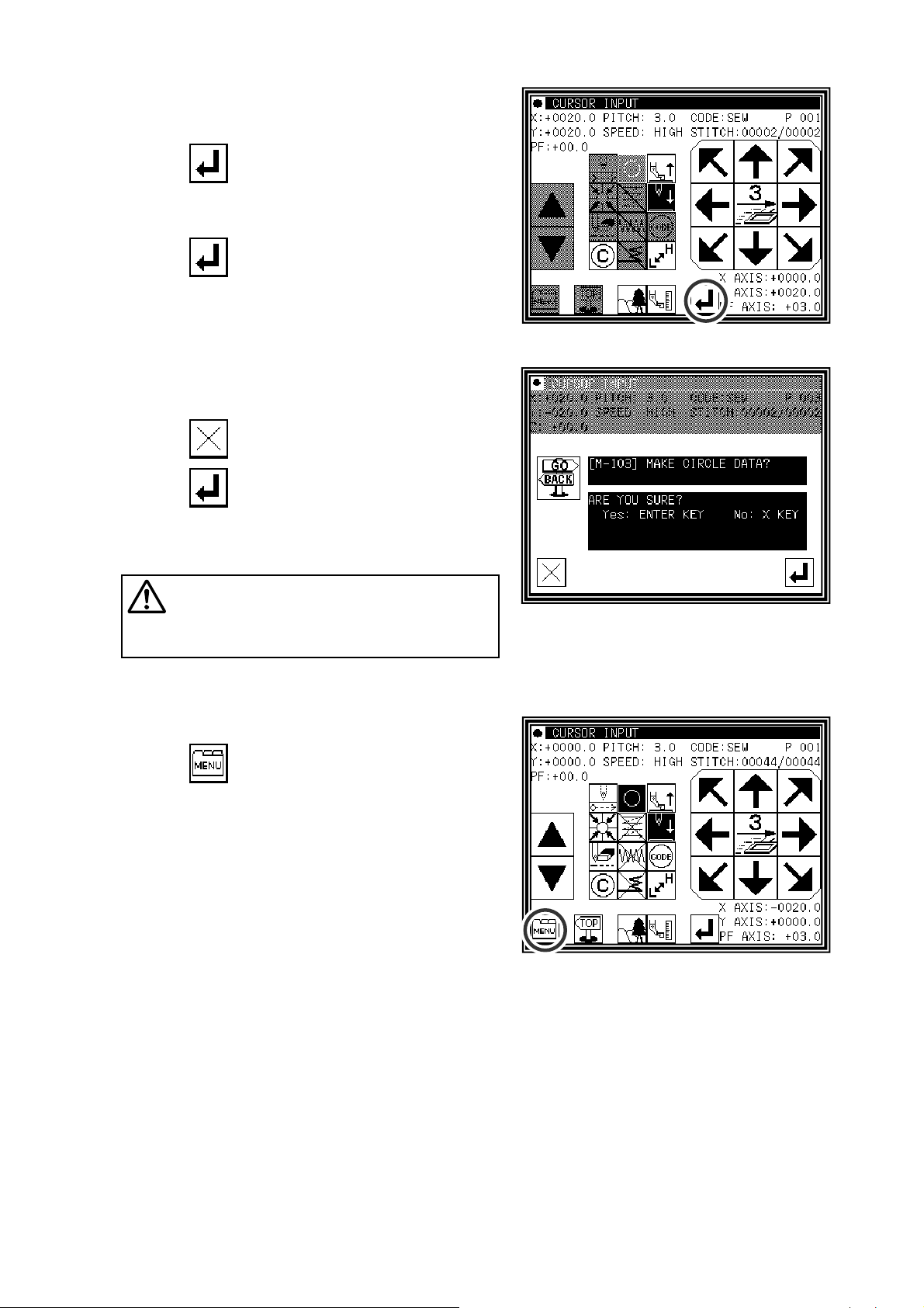
(5)Creating the circle input data
►
The confirmation message "Create circle" will appear.
►
Press to return to the point C data entry panel.
►
Press and start creation of the circle input
data.
►
A message indicating that the data is being created
will appear.
Caution
move to the current position after the data is
created.
Note that the work holder will
(6)Completing circle input
►
Press
.
[7] - 9
Page 40
(7)Inputting the return/end code
►
Press .
(
Data on feed data to the home position and the end
code will be created.)
Caution
The work holder will
automatically return to the home position. Take
care when the needle is lowered, etc.
►
A prompt for home position return will appear.
Press
Caution
.
The needle will rise to the UP position.
If the needle is not at the UP position, it may lower
once and then return to the UP position.
(9)Select a saving method.
►
After selecting the saving method, press icon.
(R
efer to section [5]Reading, writing and erasing data.)
►Return to the standard screen.
(10)Confirming the data
►
Confirm the data. Press the jog icons ( )
so the sewing machine movement can be confirmed.
(Even if the data input has not been completed, if the
data input last has been set, the movement can be
confirmed in the same manner.)
►
If the data must be modified, refer to section [11]
Modification mode Modifying the stitching data.
[7] - 10
Page 41
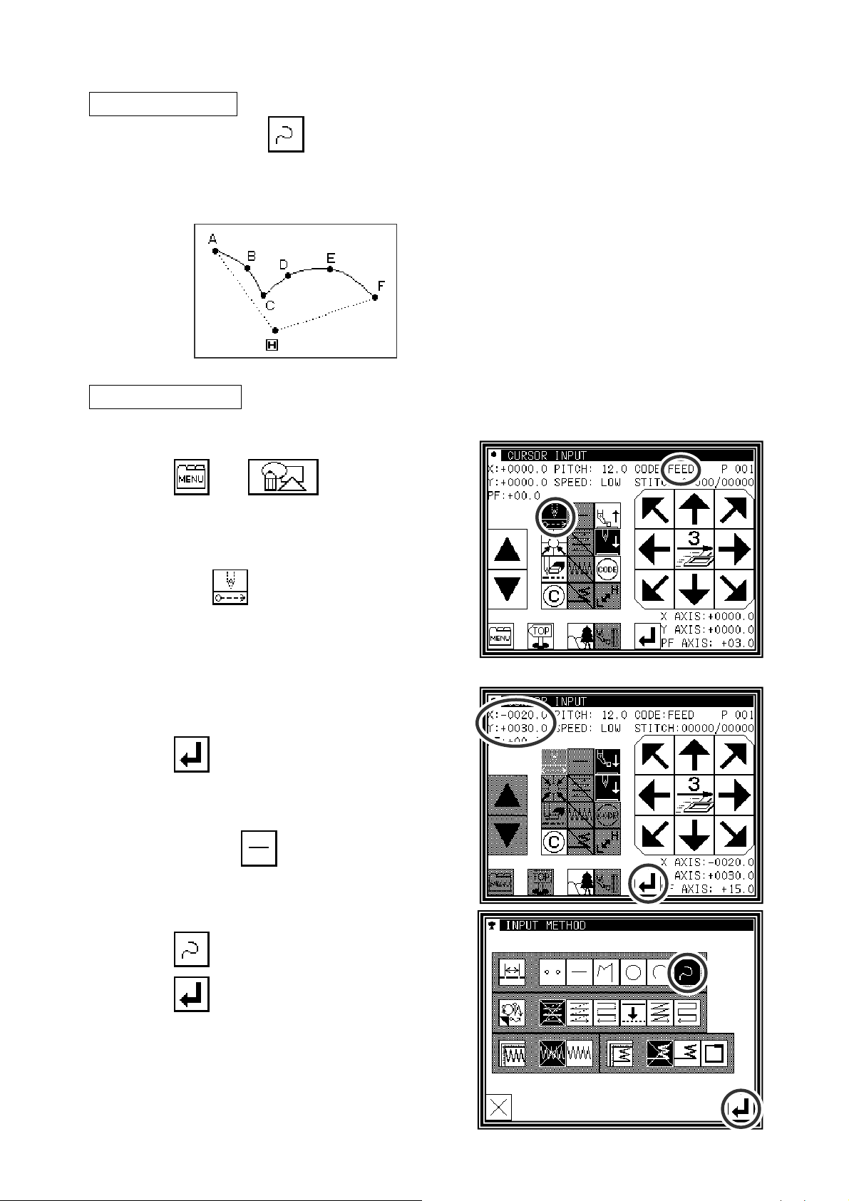
4.Curve input
Operation points
▪ Designate curve input ( )
▪ Up to 300 points can be input (A curve, passing through the current position and the input points, is
created.)
▪ A delimiter point can be inserted at a pointed corner to continuously input the curve.
[Example] The following type of sewing data will be created.
A delimiter is set at the C point.
[Memo] Set the stitch length between 0.1 to 10.0mm.
Operation details
(1)Inputting feed data to A point
►
Press and on the Standard
screen. After making the various settings on the Data
Setting Input screen, the Arrow Input screen will open.
(Refer to Page[6]-2)
►
Check that the code is set to FEED. If different code
is set, press
►
Press the arrow icons and move to the A point.
(Feed data to A point.)
and set the code to FEED.
(2)Setting feed data to A point
►
The movement amount can be confirmed.
►
Press to set the data.
(Data on feed data to point A will be created.)
►
To change the stitching type to "CURVE INPUT",
press the input method setting icon.
(In this case, the
icon.)
(3)Designating curve input
►
Press .
►
Press and set the data.
►
The system will return to the arrow input screen.
[7] - 11
Page 42

(4)Setting B point
►
Press the arrow mark icon to move to point B.
►
Press to determine point B.
(5)Setting C point
►
Press the arrow mark icon to move to point C.
►
Press to determine point C.
►
Press again to enter the breakpoint.
(6)Inserting a delimiter point
►
The data creation confirmation message "Create
breakpoint data" will appear.
►
Press to return to the point C data entry
screen.
►
Press . The breakpoint will be set here.
(7)Setting the D point, E point and F point, and setting the curve input
►
The Arrow Input screen will reappear.
►
Press the arrow icons, and move to the D point.
►
Press to determine point D.
►
Press the arrow icons again, and move to the E point.
►
Press to determine point E.
►
Press the arrow icons again, and move to the F point.
►
Press to determine point F.
(Up to 300 points can be input.)
►
At the completion of all point data entry, press again to create data.
[7] - 12
Page 43

(8)Creating the curve input
►
The data creation confirmation message "Create
breakpoint data" will appear.
►
Press to return to the last point input screen.
►
Press to start creation of the curve input data.
►
A message indicating that the data is being created
will appear.
(9)Completing curve input creation
►
Press .
(10)Inputting the return/end code
►
Press .
(
Data on feed data to the home position and the end
code will be created.)
Caution
The work holder will automatically
return to the home position. Take care when the
needle is lowered, etc.
►
A prompt for home position return will appear.
Press
Caution
.
The needle will rise to the UP position.
If the needle is not at the UP position, it may lower
once and then return to the UP position.
(9)Select a saving method.
►
After selecting the saving method, press icon.
(R
efer to section [5]Reading, writing and erasing data.)
►Return to the standard screen.
[7] - 13
Page 44

(10)Confirming the data
►
Confirm the data. Press the jog icons ( )
so the sewing machine movement can be confirmed.
(Even if the data input has not been completed, if the
data input last has been set, the movement can be
confirmed in the same manner.)
►
If the data must be modified, refer to section [11]
Modification mode Modifying the stitching data.
Memo If the distance between the curve start point and the end point is less than 0.5 mm, the pattern will
be regarded as the "closed pattern", and the same coordinate value will be automatically set for
both the start point and end point.
Precautions for inputting a curve
►
For shape data as shown below, continuous curve input is possible by selecting a delimiter point where
the corner is pointed (K point).
(This can also be applied for noncontinuous points such as for offset stitching, multiple stitching, and
reverse multiple stitching.)
[7] - 14
Page 45

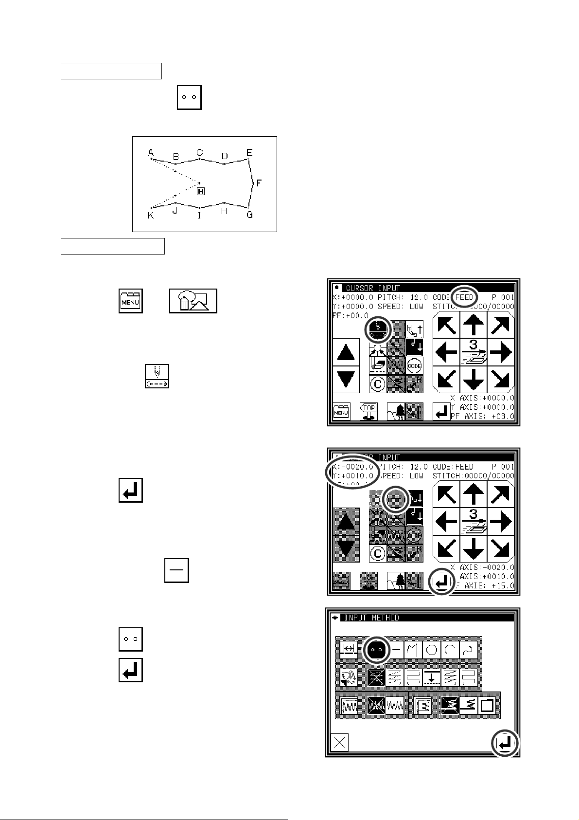
5.Broken line input
Operation points
▪ Designate broken line input( )
▪ Up to 300 points can be input (A broken line connecting the current position and input points is
created.)
[Example] The following type of sewing data will be created.
Operation details
(1)Inputting feed data to A point
►
Press and on the Standard
screen. After making the various settings on the Data
Setting Input screen, the Arrow Input screen will open.
(Refer to Page[6]-2)
►
Check that the code is set to FEED. If different code
is set, press
►
Press the arrow icons and move to the A point.
(Feed data to A point.)
and set the code to FEED.
(2)Setting feed data to A point
►
The movement amount can be confirmed.
►
Press to set the data.
(Data on feed data to point A will be created.)
►
To change the stitching type to "Broken line input",
press the input method setting icon.
(In this case, the icon.)
(3)Designating broken line input
►
Press .
►
Press and set the data.
►
The system will return to the arrow input screen.
[7] - 15
Page 46

(4)Setting B point , C point , D point , E point
►
Press the arrow mark icon to move to point B.
►
Press to determine point B.
►
Press the arrow mark icon to move to point C.
►
Press to determine point C.
►
Press the arrow mark icon to move to point D.
►
Press to determine point D.
►
Press the arrow mark icon to move to point E.
►
Press to determine point E.
(Up to 300 points can be input.)
►
At the completion of all point data entry, press again to create data.
(5)Creating the broken line input
►
The data creation confirmation message "Create
breakpoint data" will appear.
►
Press to return to the last point input screen.
►
Press to start creation of the broken line input
data.
►
A message indicating that the data is being created
will appear. (The broken line will be created.)
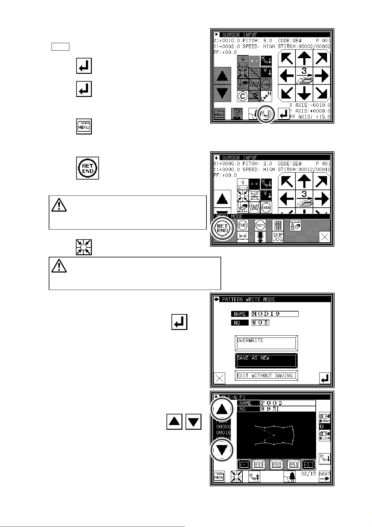
(6)Creating the broken line input
►
Press
.
[7] - 16
Page 47

(7)Inputting the return/end code
►
Press .
(
Data on feed data to the home position and the end
code will be created.)
Caution
The work holder will
automatically return to the home position. Take
care when the needle is lowered, etc.
►
A prompt for home position return will appear.
Press
Caution
.
The needle will rise to the UP position.
If the needle is not at the UP position, it may lower
once and then return to the UP position.
(8)Select a saving method.
►
After selecting the saving method, press icon.
(R
efer to section [5]Reading, writing and erasing data.)
►Return to the standard screen.
(9)Confirming the data
►
Confirm the data. Press the jog icons ( )
so the sewing machine movement can be confirmed.
(Even if the data input has not been completed, if the
data input last has been set, the movement can be
confirmed in the same manner.)
►
If the data must be modified, refer to section [11]
Modification mode Modifying the stitching data.
Memo
If the distance between the broken line start point and the end point is less than 0.5 mm, the
pattern will be regarded as the "closed pattern", and the same coordinate value will be
automatically set for both the start point and end point.
[7] - 17
Page 48
6.Point input
Operation points
▪ Designate point input( )
(The distance between the points must be within 20mm)
[Example] The following type of sewing data will be created.
Operation details
(1)Inputting feed data to A point
►
Press and on the Standard
screen. After making the various settings on the Data
Setting Input screen, the Arrow Input screen will open.
(Refer to Page[6]-2)
►
Check that the code is set to FEED. If different code
is set, press
►
Press the arrow icons and move to the A point.
(Feed data to A point.)
and set the code to FEED.
(2)Setting feed data to A point
►
The movement amount can be confirmed.
►
Press to set the data.
(Data on feed data to point A will be created.)
►
To change the stitching type to "POINT INPUT",
press the input method setting icon.
(In this case, the
icon.)
(3)Designating point input
►
Press .
►
Press and set the data.
►
The system will return to the arrow input screen.
[7] - 18
Page 49
(4)Setting B point to K point
►
Press the arrow mark icon to move to point B.
Memo The distance between the points must be within
20mm.
►
Press to determine point B.
►
Press the arrow mark icon to move to point C.
►
Press to determine point C.
►
The Arrow Input screen will reappear, so press the
arrow icons and move to the D point to K point in the
same manner.
►
Press .
(5)Inputting the return/end code
►
Press .
(
Data on feed data to the home position and the end
code will be created.)
Caution
return to the home position. Take care when the
needle is lowered, etc.
►
A prompt for home position return will appear.
The work holder will automatically
Press
Caution
.
The needle will rise to the UP position.
If the needle is not at the UP position, it may lower
once and then return to the UP position.
(6)Select a saving method.
►
After selecting the saving method, press icon.
(R
efer to section [5]Reading, writing and erasing data.)
►Return to the standard screen.
(7)Confirming the data
►
Confirm the data. Press the jog icons ( )
so the sewing machine movement can be confirmed.
(Even if the data input has not been completed, if the
data input last has been set, the movement can be
confirmed in the same manner.)
►
If the data must be modified, refer to section [11]
Modification mode Modifying the stitching data.
[7] - 19
Page 50
7.Code data input
Operation points
▪ Designate code data input( )
▪ Select and input the code data from the code data list
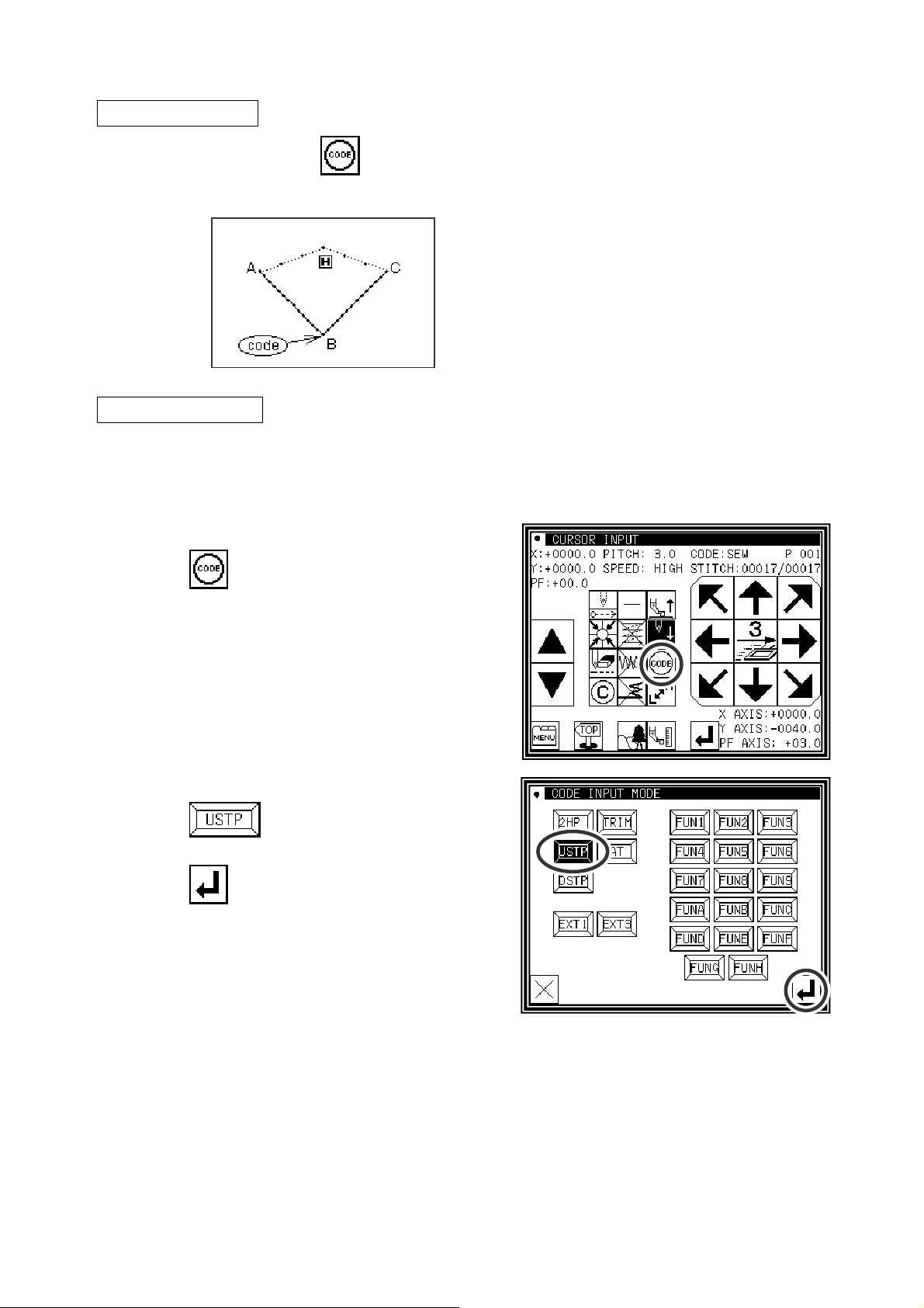
[Example] The following type of sewing data will be created.
Operation details
(1)Inputting a linear line from A point to B point
Input the "NEEDLE UP HALT" code at the B point
between the A-B point linear line and B-C linear line.
[Memo] Code data cannot be inserted when inputting
with a linear, circle, arc, curve or polygonal
line. To input, add the code data with the
modification mode. (Input between the linear
lines is possible as shown in the example.)
►
Input a linear line from the A point to B point using the linear input procedures.
(2)Inputting the code data (NEEDLE UP HALT)
►
Press .
►
Press .
(Refer to the code list of the next page.)
►
Press to set the code.
(The "NEEDLE UP HALT" code will be created.)
►
The system will return to the arrow input screen.
(3)Inputting a linear line from B point to C point
►
Input a linear line from the B point to C point using the linear input procedures.
(4)Inputting the return end and the data completion
►
The return end is input and it is completion.
[7] - 20
Page 51
■List of code data
Code Function Code Function
2HP
USTP
DSTP
TRIM
BAT
EXT1 : Extension code
ASRT : Automatic start after stopping
EXT3 : Extension code
F1_H~FH_H : FN (1~H) Output ON
F1_L~FH_L : FN (1~H) Output OFF
2nd home position
Needle UP halt
Needle DOWN halt
Thread trimming
Basting
FUN1
FUN2
FUN3
FUN4
FUN5
FUN6
FUN7
FUN8
FUN9
FUNA
FUNB
FUNC
FUND
FUNE
FUNF
FUNG
FUNH
Function code 1
Function code 2
Function code 3
Function code 4
Function code 5
Function code 6
Function code 7
Function code 8
Function code 9
Function code A
Function code B
Function code C
Function code D
Function code E
Function code F
Function code G
Function code H
Making method of using BAT (Basting or more than 20mm stitch length) code.
The sewing data which exceeds the stitch length limitation of 20mm can be made by using this BAT code.
[Example] The following type of sewing data will be created.
(1)Input the "BAT" codes after input the feed data to A point
►
Press .
[7] - 21
Page 52
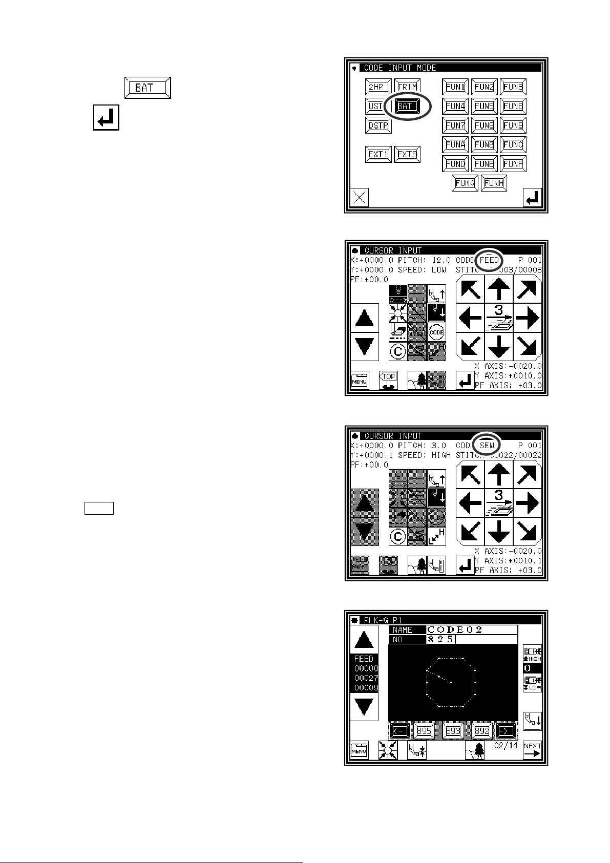
(2)Code selection on code selection screen
►
Press .
►
decides to pushing.
(The BAT code is made.)
►
Returns to the arrow input screen.
(3)Arrow input screen
►
Does not become SEW (Sewing) input mode and it is
FEED input mood after input the "BAT" code.
►
Input the feed data to the next B point.
►
Input the "BAT" code and the feed data from H point to
A point repeating.
(4)The pattern data input before return end
►
It is not input the "BAT" code before the last of return
end but the sewing data is input. Inputs here only by 1
stitch of the straight line.
Memo The purpose of inputting the sewing data at the
end is to put the thread trimmer (TRIM) code by
the automatic operation when the return end is
input. The thread trimmer(TRIM) code cannot be
input after the sewing data.
(5)Input the return end and the data completion
►
The return end is input and it is completion.
[7] - 22
Page 53

About Extension code 1 (EXT1)
* Press the Extension screen display key , and press
►”ASRT” : Automatic start after stopping
Using the numeric keypad, set the time that stops until
starting automatically.
.
About the Function code (FUN1~FUNH)
Output signal FN1 to FNH can be controlled by set in the pattern data. (Refer to P.[14]-9)
When code data FUN1 is read in the pattern data while sewing, FN1 output is reversed.
(same as FUN2~FUNH)
[example.Timing chart when FUN1 code is set in the pattern data]
Progress of pattern data•→•→•→•→•→FUN1→•→•→•→•→FUN1→•→•→•→FUN1→•→•→•→•→
FN1 output signal
OF
ON
ON
OF
Caution
PLEASE DO NOT MIX
with FUN1~FUNH code in the same data.
F1_H~FH_H or F1_L~FH_L code
[7] - 23
Page 54
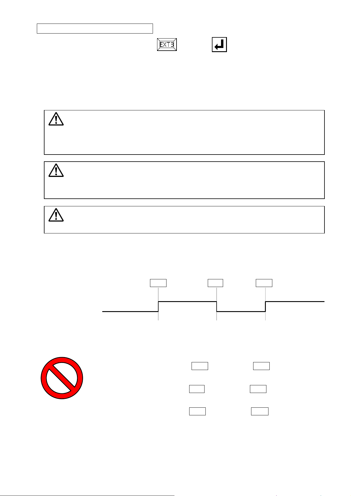
About Extension code 3 (EXT3)
* Press the Extension screen display key , and press
.
These signal also controls output signal FN1~FNH as well as above mentioned extension code
(FUN1~FUNH). (Refer to P.[14]-9)
When code data F1_H is read in the pattern data while sewing, FN1 output is turned on.
When code data F1_L is read in the pattern data while sewing, FN1 output is turned off.
(Same as F2_H~FH_H、F2_L~FH_L)
Caution
PLEASE DO NOT USE [F1_H] CODE REPEATEDLY AFTER THE SAME CODE.
PLEASE DO NOT USE [F1_L] CODE REPEATEDLY AFTER THE SAME CODE.
PLEASE USE [F1_H] CODE AND [F1_L] CODE ALTERNATELY.
( Also F2_H~FH_H,F2_L~FH_L)
Caution
F1_L] CODE MUST BE INPUTTED AFTER [F1_H] CODE IS ALREADY
[
INPUTTED.
(Also F2_H~FH_H、F2_L~FH_L)
Caution
PLEASE DO NOT MIX
F1_L~ FH_L code in the same data.
FUN1~FUNH code with F1_H~ FH_H or
[example.Timing chart when F1_H/F1_L code is set into the pattern data]
Progress of pattern data•→•→•→•→•→F1_H→•→•→•→•→F1_L→•→•→•→F1_H→•→•→•→•→•
FN1 output signal
OF
OF
ON ON
OF
[Example of prohibition]
[Same code repetition]・→・→・→F1_H→・→・→・→F1_H→・→・→・
[Start from off code] ・→・→・→F1_L→・→・→・→F1_H→・→・→・
[Mixed use] ・→・→・→F1_H→・→・→・→FUN1→・→・→・
[7] - 24
Page 55
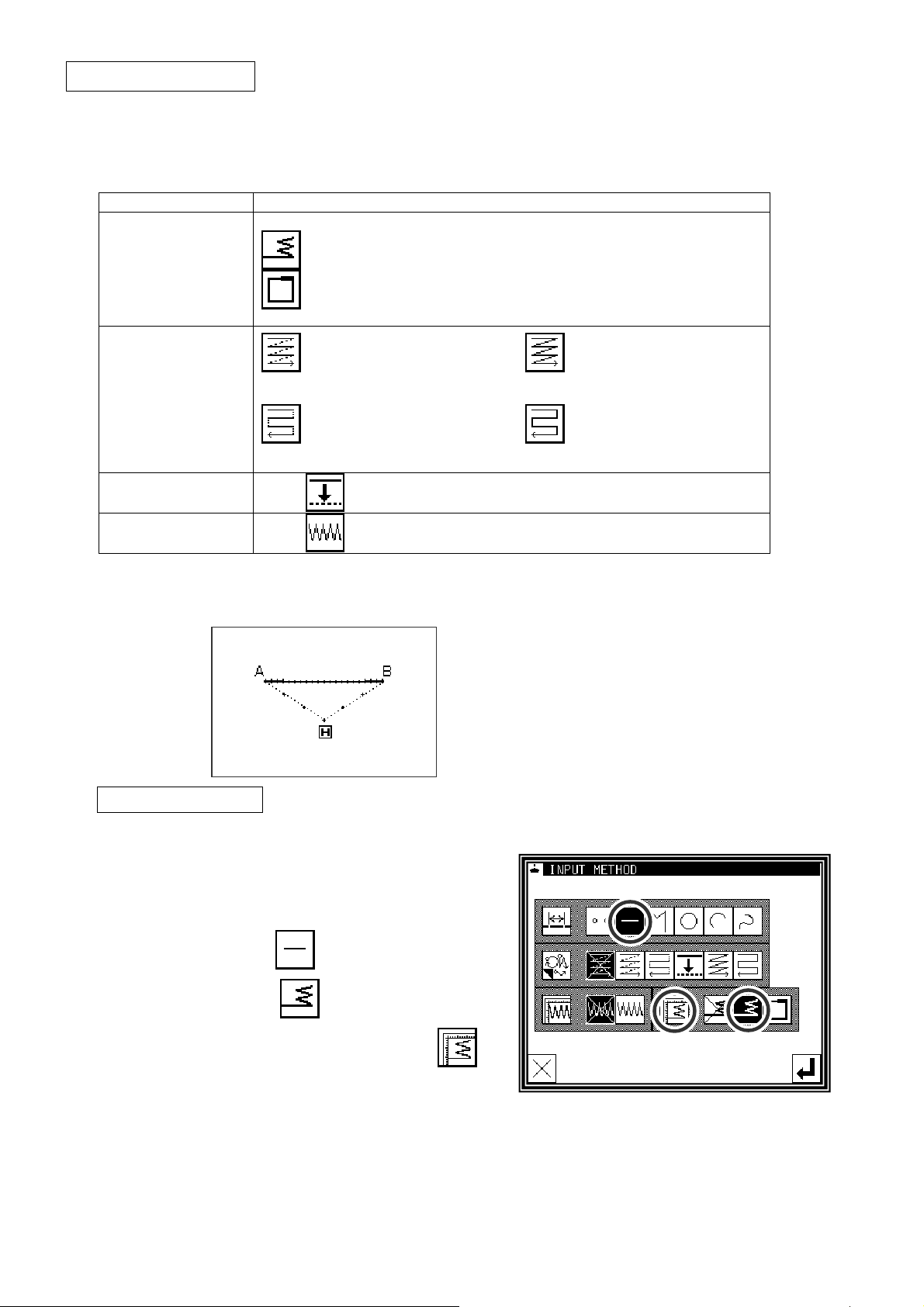
Application inputs
Various types of stitching, including back tacking, multiple stitching, offset stitching and zigzag stitching can
be carried out. Various types of stitching data can be created by combining the basic inputs and these types.
(Refer to section [9] Table of stitching type combinations.) Note that the application inputs cannot be
combined with point inputs to input data.
Function icon
Back tacking
([7]-25)
Multiple stitching
([7]-29)
Start/end back tacking
Overlap back tacking
Multiple stitching
(Feed data specifications) (stitching specifications)
Reverse multiple stitching
(Feed data specifications) (stitching specifications)
Offset stitching
([7]-32)
Zigzag stitching
([7]-34)
8.Back tacking (start/end back tacking)
[Example] The following type of sewing data will be created.
With the linear input, the N mode and 3-stitch
back tacking will be inserted for both the start and
end of stitching. (The bold sections indicate
start/end back tacking.)
Multiple stitching
Reverse multiple stitching
Operation details
(1)Setting the input method
►
Set the feed data from the home position to the A
point with the procedures for linear input, and open
the Input Method Setting screen.
►
Press Linear Input .
►
Press back tacking .
►
Press the back tacking details setting icon .
[7] - 25
Page 56
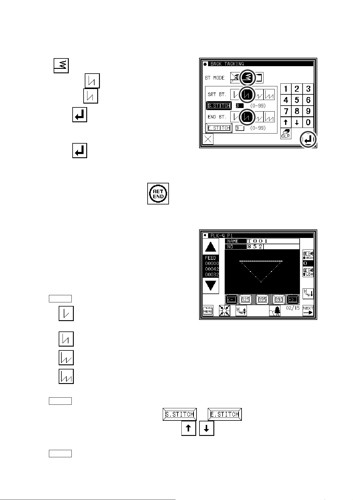
(2)Setting the back tacking details
►
The details are set on this screen.
(The details set here are,
(start/end back tacking),
start mode
end mode
►
Press to determine these set values.
►
The system will return to the input method setting
screen.
►
Press to determine the set values.
►
The system will return to the arrow input screen.
►
Determine the B point with the linear input procedures, and create a linear line.
►
After creating the linear line, press
(N mode), three start stitches,
(N mode), three end stitches.)
.
(3)Confirming the data
►
The start/end back tacking data for the linear line has
been created.
Memo Regarding back tacking mode
V mode: Back tacking will be performed only
once.
N mode: Back tacking will be performed twice.
M mode: Back tacking will be performed third.
W mode: Back tacking will be performed fourth.
Memo Regarding number of stitches
Press the icon of the desired position ( or ) to invert the icon.
After that, set data using the numeric icons or
.
Memo Press the back tacking data setting icon on the arrow input screen to directly display the
"detailed back tacking data setting" screen.
[7] - 26
Page 57
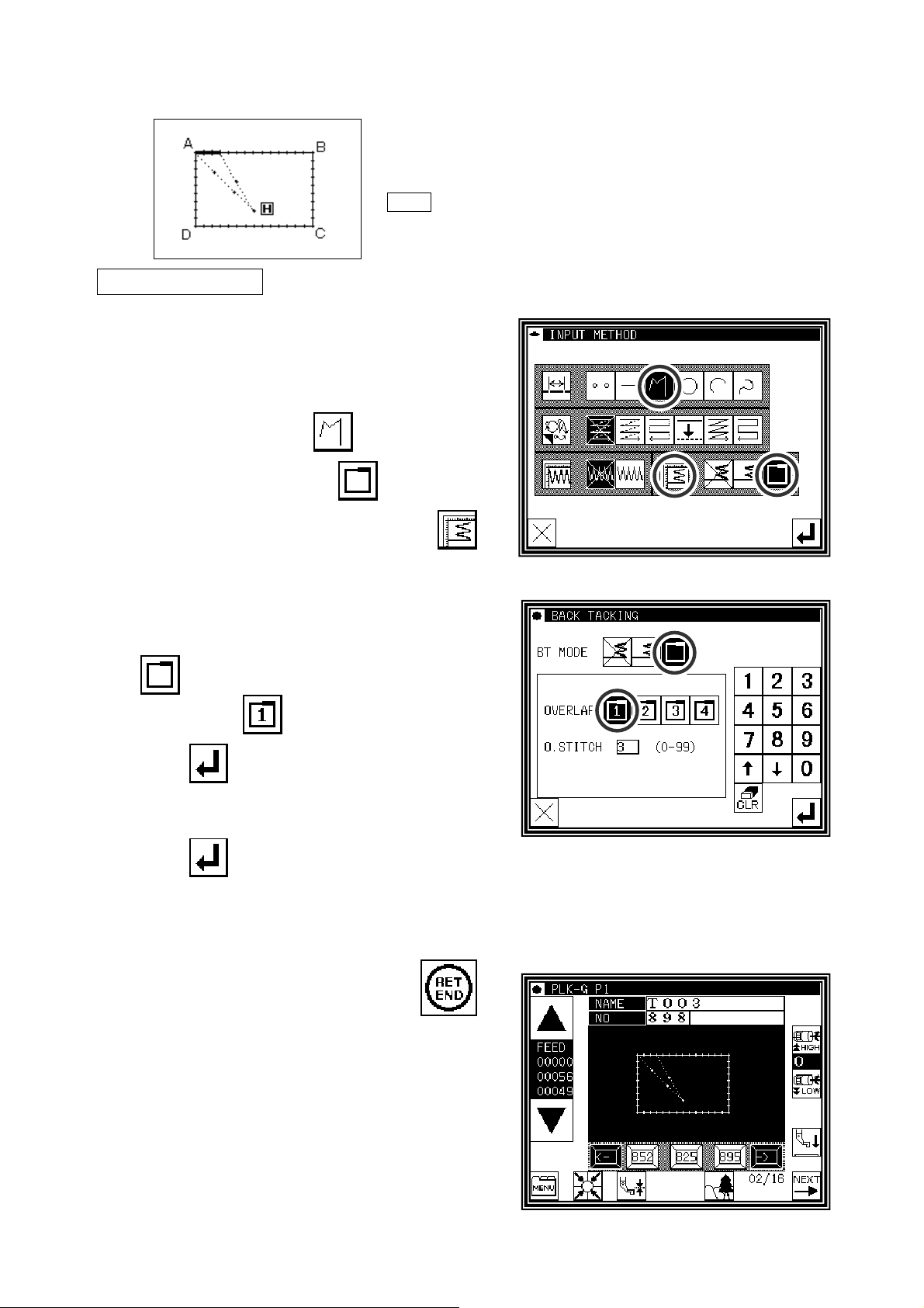
9.Back tacking (overlap back tacking)
[Example] The following type of sewing data will be created.
Input a rectangle as a broken line, and then insert overlap back
tacking at the end. (The overlap mode is entered once; three
overlap stitches are made.) (The bold section is the overlap back
tacking section.)
Memo It is a shutting figure in the figure made in [Broken line],
[Circle], [Curve] to be able to do multiple back tacking. That
Operation details
(1)Setting the input method
►
Set the feed data from the home position to the A
point with the procedures for broken line input, and
open the Input Method Setting screen.
is, it is not possible to do by combining "Straight line" in the
plural in the enclosed figure. Moreover, it is not possible to
do by plural combining "Straight line" and "Curve" also even
in the enclosed figure. The multiple back tacking can be
made only by 1 place per 1 "Sewing" data origination.
►
Press broken Line Input .
►
Press Overlap back tacking .
►
Press the back tacking details setting icon
(2)Setting the back tacking details
►
The details are set on this screen.
(The details set here are,
(overlap back tacking),
overlap mode
►
Press to determine these set values.
►
The system will return to the input method setting
screen.
►
Press to determine the set values.
, three overlap stitches.)
.
►
The system will return to the arrow input screen.
►
Determine the B, C, D and A points with the broken line procedures, and create the broken line data. (A
broken line having overlap back tacking will be created.)
►
After creating the broken line data,input
(3)Confirming the data
►
The overlap back tacking will be created with the
rectangle made with broken lines.
.
[7] - 27
Page 58

Memo Overlap mode
in the overlap mode indicate the number of overlapped sections.
Memo Number of overlap stitches
This is the number of stitches at the overlapped section. (Set a value between 0 and 99.)
Memo If the distance between the broken line start point and the end point is 0.5 mm or more, the
overlap back tacking data will not be created.(If the distance between the broken line start point and
the end point is less than 0.5, the pattern will be regarded as the "closed pattern", and the same
coordinate value will be automatically set for both the start point and end point.
)
[7] - 28
Page 59
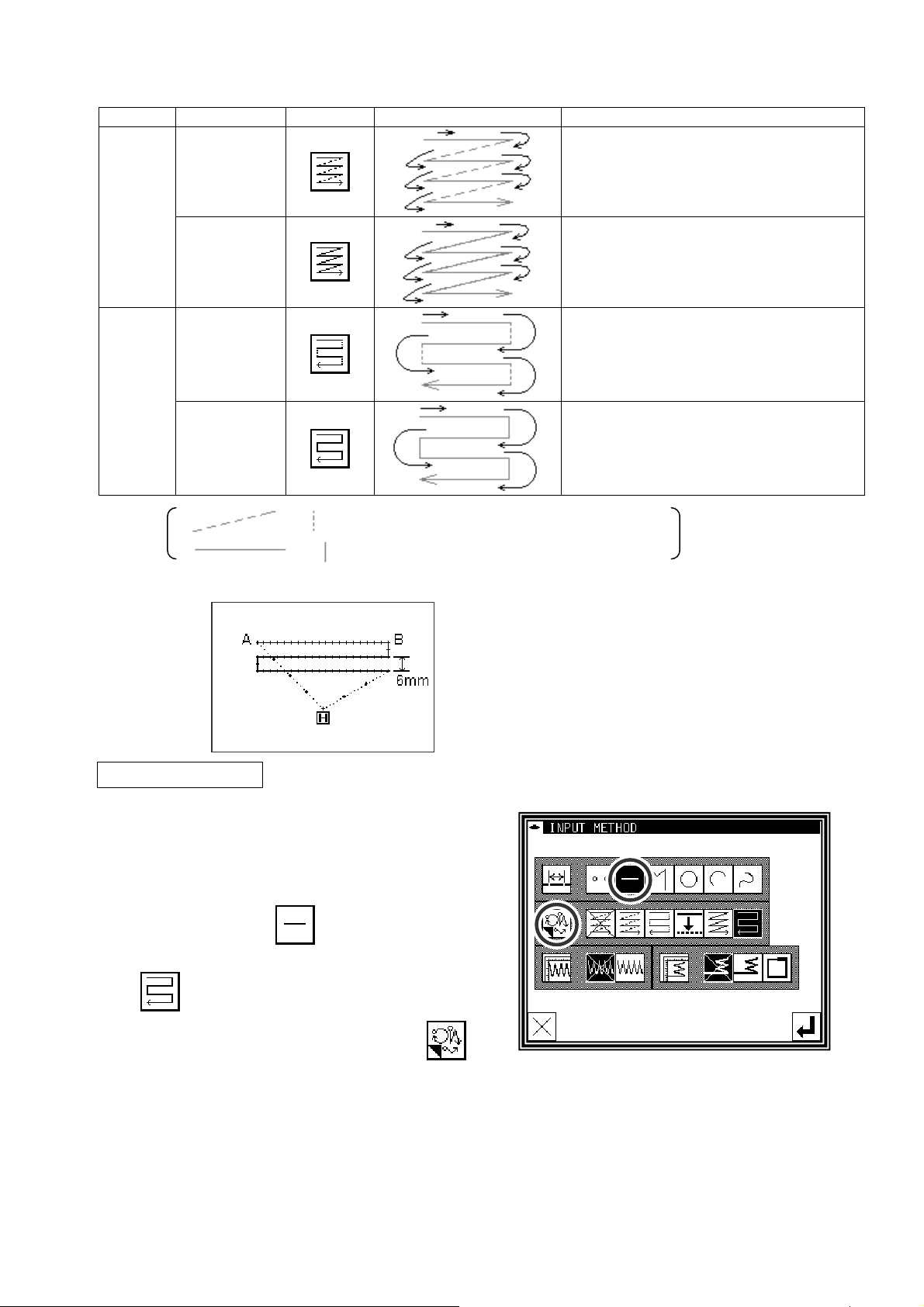
10.Multiple stitching
Type Connection icon Stitching data image Explanation
Feed data
Multiple
Stitching
Feed data
Reverse
multiple
Stitching
and (dotted line) in the image indicates "feed data".
and (solid line) in the image indicates "stitching".
[Example] The following type of sewing data will be created.
"Stitching" in a set direction is connected
with "feed without stitching".
"Stitching" in a set direction is connected
with "stitching".
"Stitching" in alternating reverse
directions is connected with "feed data".
"Stitching" in alternating reverse
directions is connected with "stitching".
Operation details
(1)Setting the input method
►
Set the feed data from the home position to the A
point with the procedures for linear input, and open
the Input Method Setting screen.
►
Press Linear Input .
►
Press Reverse Multiple (stitching specifications)
.
►
Press the reverse multiple details. Press .
Create the linear reverse multiple (stitching
specification) data.
(The multiple distance is 6mm, the number of
times is three, the direction is right.)
[7] - 29
Page 60

(2)Setting the reverse multiple stitching details
►
The details are set on this screen.
(Press
and the number of times to 3.)
►
Press to set the data.
►
The system will return to the input method setting
screen.
►
Press to set the data.
►
The system will return to the arrow input screen.
►
Determine the B point with the linear input procedures, and create a linear line. (A straight line having
reverse multiple (stitching specification) will be created.)
►
After creating the linear line, input
and , and set the distance to 6.0,
.
(3)Confirming the data
►
Linear reverse multiple data has been created.
Memo Direction
When creating multiple stitching to the left of the input stitching line, press (left side).
When creating multiple stitching to the right of the input stitching line, press (right side).
Memo Distance
This is the distance between the multiple stitching and adjacent line. Set between 0.0mm and 20.0mm.
To input the distance data, press the DISTANCE icon to invert the icon. After that, input the data
using the numeric icons or the up/down arrow mark icons.
Memo Number of times
Set the number of multiple stitching layers. Set between 2 and 9. To input the number of times, press
the NUMBER OF TIMES icon to invert the icon. After that, input the data using the numeric icons or
the up/down arrow mark icons.
Memo Or press the MULTI, REVERSE MULTI, OFFSET icon on the arrow input screen to directly
display the MULTI, REVERSE MULTI, OFFSET setting screen.
[7] - 30
Page 61

Memo (A) It is for the combination data of a curve input and multiple (offset) sew.
The data like the figure below (right) is made as shown in the figure below (left) when curves which
pass point 2, point 3, and point 4 after an feed from the home position to point 1 are combined with
multiple sewing and inputs.(Distance=10mm and 2 times of "Frequency")
The distance of the multiple data becomes "It is narrow" the data as shown in figure.
They are not like to make this partially narrow multiple data, to make a constant distance multiple data
as much as possible, please input 2' between 2 and 3 as shown in the figure below (left). The multiple
data as shown in the figure below (right) is made.
Memo (B) It is for the combination data of a curve input (Broken line input) and multiple sew.
The data like the figure below (right) is made as shown in the figure below (left) when curves which
pass point 2, point 3, and point 4 after an feed from the home position to point 1 are combined with
multiple sewing and inputs.(Distance=8mm and 4 times of "Frequency")
The data is made in the curve that the fourth curve is different as understood from figure(right).
When the virtual input point which makes the multiple is requested by the operation, such a situation
like the figure below, the reason for it is to intersect in the multiple.
Moreover, such a situation changes variously depending on the condition of the input point etc. of
"Distance", "Frequency" of the multiple data, and the curve.
Please use a variety of trying.
[7] - 31
Page 62

11.Offset stitching (with overlap back tacking)
[Example] The following type of sewing data will be created.
Input offset stitching with overlap back tacking as a
broken line. (Set the offset distance to "5.0 mm",
direction to "right", overlap back tacking mode to "1",
and number of stitches to "3".)
(The bold section indicates the overlap back tacking
section.)
(The dotted line (- - - - - - -) indicates the actual input
line (position before offset.))
Operation details
(1)Setting the input method
►
Set the feed data from the home position H to the A
point with the procedures for broken line input, and
open the Input Method Setting screen.
►
Press Broken Line Input .
►
Press Offset .
►
Press Overlap Back Tacking .
►
Set the application input details. Press .
(2)Setting the offset details
►
The details are set on this screen.
(Press
The offset amount can be set in 0.1mm increments
between 0 and 20mm.
►
After inputting the details, press to set the
data.
, and set the distance to 5.0.)
(3)Setting the back tacking details
►
After returning to the Input Method Setting screen,
press the back tacking details setting icon
.
[7] - 32
Page 63

(4)Setting the overlap back tacking details
►
The details are set on this screen.
(The details set here are, (overlap back tacking),
overlap mode , three overlap stitches.)
►
Press to set the data.
►
The system will return to the input method setting
screen.
►
Press to set the data.
►
The system will return to the arrow input screen.
►
Determine the B, C D and A points with the broken line procedures, and create the broken line data.
►
After creating the broken line data, input
.
(5)Confirming the data
►
The offset data will be displayed on the image screen.
Memo Or press the MULTI, REVERSE MULTI, OFFSET icon on the arrow input screen to directly
display the MULTI, REVERSE MULTI, OFFSET setting screen.
[7] - 33
Page 64
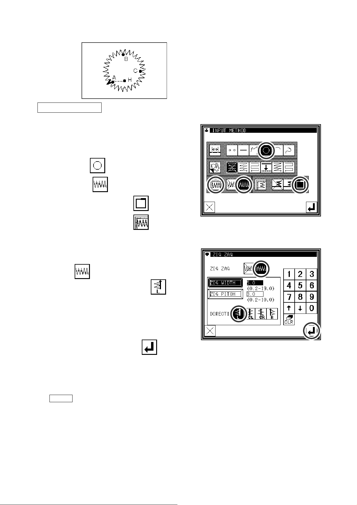
12.Zigzag stitching (with overlap back tacking)
[Example] The following type of sewing data will be created.
Input zigzag stitching with overlap back tacking as
circle. (The zigzag deflection width will be 5.0mm, the
feed amount will be 3.0mm, the direction is left,. the
overlap back tacking mode will be carried out once, and
three overlap stitches will be made.)
(The bold section is the overlap back tacking section.)
Operation details
(1)Setting the input method
►
Set the feed data from the home position H to the A
point with the procedures for broken line input, and
open the Input Method Setting screen.
►
Press Circle .
►
Press Zigzag .
►
Press Overlap Back Tacking .
►
Set the zigzag details. Press .
(2)Setting the zigzag details
►
The details are set on this screen.
(Press
amount to 3.0 and direction to "left"
(
The zigzag deflection width can be set in 0.1mm
increments between 0.2 and 19.0mm.)
(The zigzag feed amount can be set in 0.1mm
increments between 0.2 and 10.0mm.)
(Refer to the "Deflection width, feed amount and
creation direction" section given later for details.)
, set the deflection width to 5.0, feed
.)
►
After inputting the details, press to set the
data.
Memo To input the stitch width/length, press the STITCH WIDTH/LENGTH icon to invert the icon. After
that, input the data using the numeric icons or the up/down arrow mark icons.
[7] - 34
Page 65
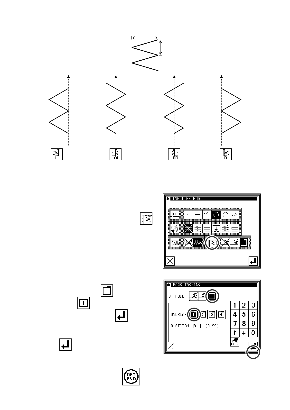
Deflection width, feed amount and creation direction
Deflection
width
Feed amount
Travel direction
left side
Travel direction
center
Starts from left side
(3)Setting the back tacking details
►
After returning to the Input Method Setting screen,
press the back Tacking Details Setting icon
(4)Setting the overlap back tacking details
►
The details are set on this screen.
(The details set here are, ,
.
Travel direction
center
Starts from right side
Travel direction
right side
overlap mode,
►
After inputting the details, press to set the
data.
►
The system will return to the input method setting
screen.
►
Press to determine the set values.
►
The system will return to the input method setting
screen.
►
While following the circle data entry procedure, determine points B and C to create the circle data.
►
After creating the circle data, press
three overlap stitches.)
.
[7] - 35
Page 66
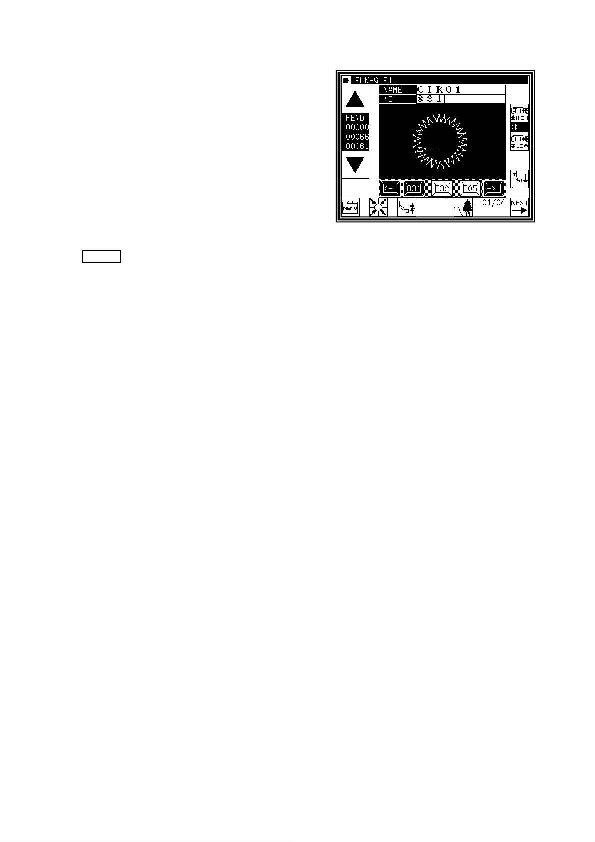
(5)Confirming the data
►
Zigzag stitching (with overlap back tacking)
Memo Or press the ZIGZAG icon on the arrow input screen to directly display the ZIGZAG setting
screen.
[7] - 36
Page 67
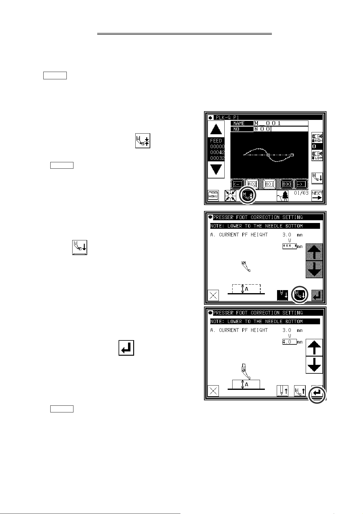
[8] Controlling the Presser Foot
1. Setting for material thickness
The lowest position when the presser foot is lowered can be corrected by following setting. Before sewing
operation, please adjust the lowest position of the presser foot.
NOTE If presser foot height is changed by mechanical adjustment, this setting can not be used.
Please use this setting, after return the presser foot height to the factory shipment condition.
(1) Display standard screen
►Press material thickness setting .
MEMO For enter to material thickness setting screen,
presser foot needs to be up position.
(2)Sets material thicknes
►Press then presser foot is lowered. Turn the hand
wheel and lowered needle to lowest position.
Then up and down arrow icons are activated.
►Press up or down arrow icon and adjust material thickness.
Setting range is from 0.0 mm to 8.0 mm by 0.2 mm
resolution.
(Example is set in 4.0 mm in right figure.)
►After setting value, press
►Setting is complete, then display is back to standard
screen.
MEMO Setting material thickness is saved (written) in sewing data.
• If material thickness is other than 0 mm, it is saved in the sewing data.
• It can be selected whether to make the preserved value of the presser foot correction effective when the pattern
data is read. Please reffer to [Program mode> Sewing pattern>HPW].
mode)
.
(Refer to P.[15]-1 for the program
[8] - 1
Page 68
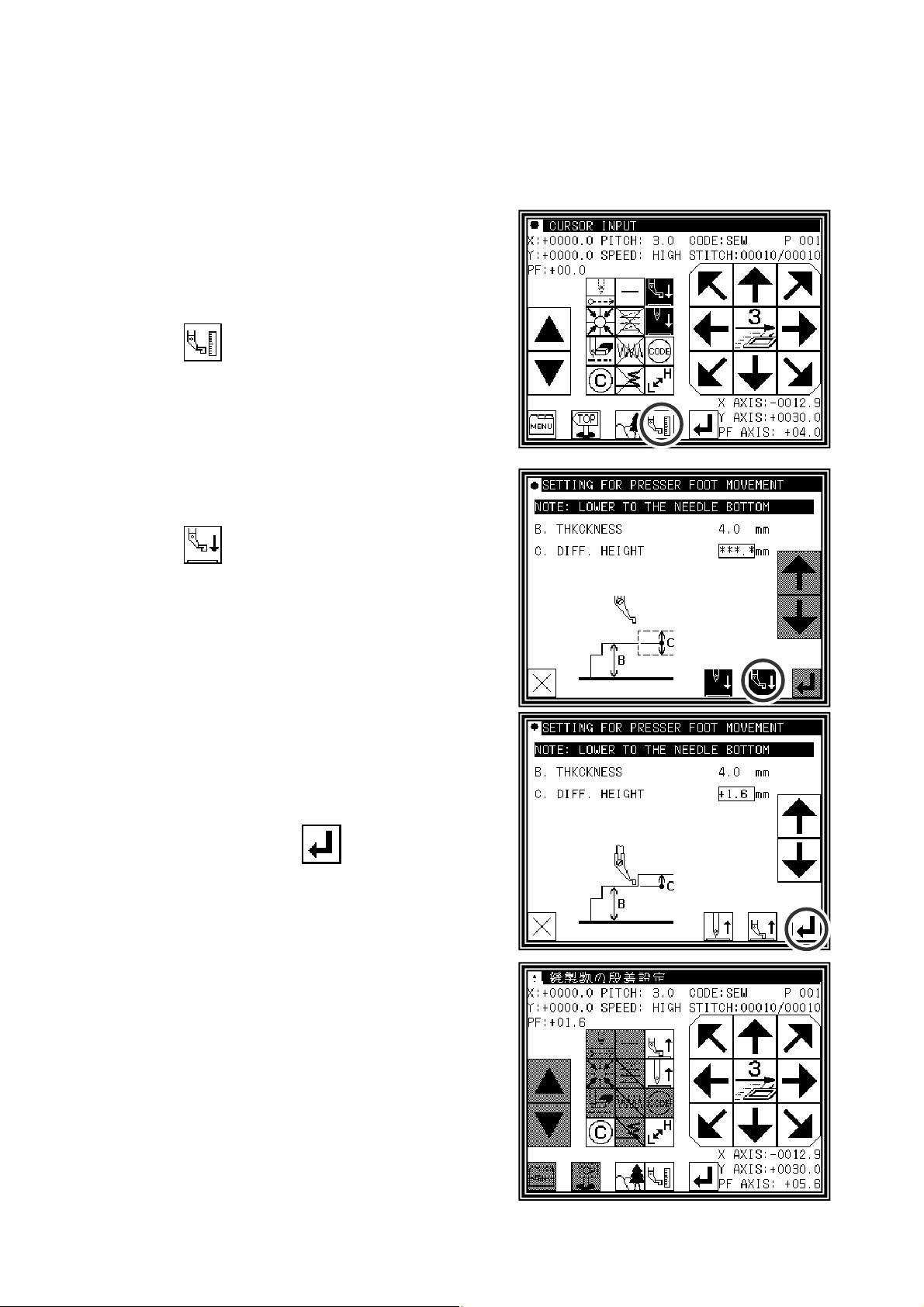
2. Setting for material step level
Presser foot height between the sewing can be changed according to the step of the material thickness.
(In change the height of the presser foot according to the situation of the sewing material, it is effective to
prevent skip stitch or prevent thread breakage.)
The method in the pattern data input is as follows. Please reffer to P.[11]-43 for the pattern data modification.
(1) On the way of pattern data input, please execute
following operation at the position where presser
foot height will be changed.
►Press
.
(2)Setting material step
►Press and presser foot is lowered. Turn the hand
wheed and needle lowered to the lowest position.
Then up and down arrow icon is activated.
► Press up and down arrow to change the presser foot height.
(example shows presser foot height = 1.6 mm.)
►After setting value, press
* Please consider interferrence between the presser foot and
the needle bar.
(3) Next setting ( if desired )
►If there is more position where presser foot height wants to
be changed, please repeat above operation (1) to (2).
.
[8] - 2
Page 69
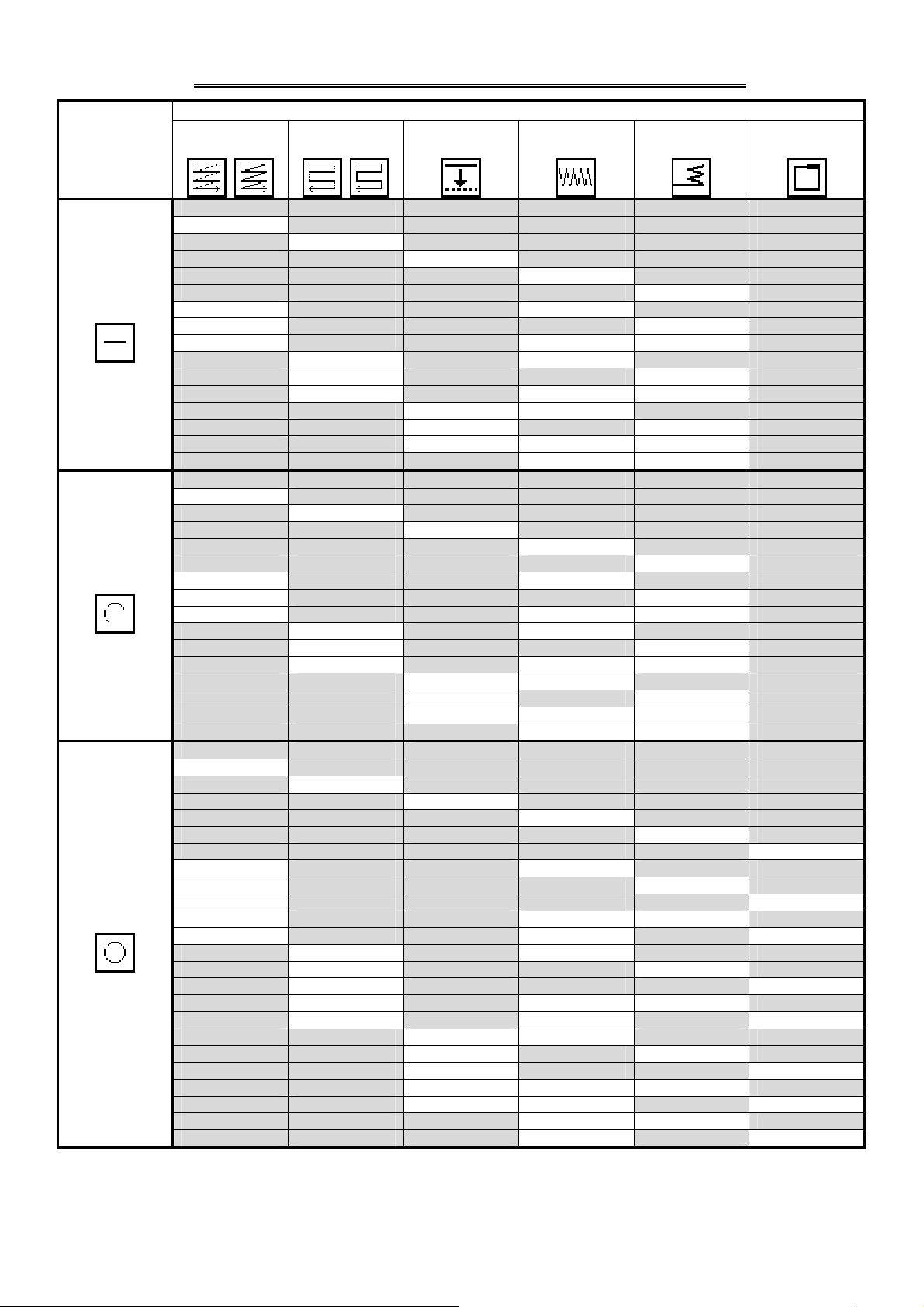
Basic input
[9] Table of stitching type combinations
Zigzag
Start/end
back tacking
Multiple
Reverse
multiple
Application input
Offset
Overlap back
tacking
Linear
Arc
Circle
○
○
○
○
○
○ ○
○ ○
○ ○ ○
○ ○
○ ○
○ ○ ○
○ ○
○ ○
○ ○ ○
○ ○
○
○
○
○
○
○ ○
○ ○
○ ○ ○
○ ○
○ ○
○ ○ ○
○ ○
○ ○
○ ○ ○
○ ○
○
○
○
○
○
○
○ ○
○ ○
○ ○
○ ○ ○
○ ○ ○
○ ○
○ ○
○ ○
○ ○ ○
○ ○ ○
○ ○
○ ○
○ ○
○ ○ ○
○ ○ ○
○ ○
○ ○
[9] - 1
Page 70
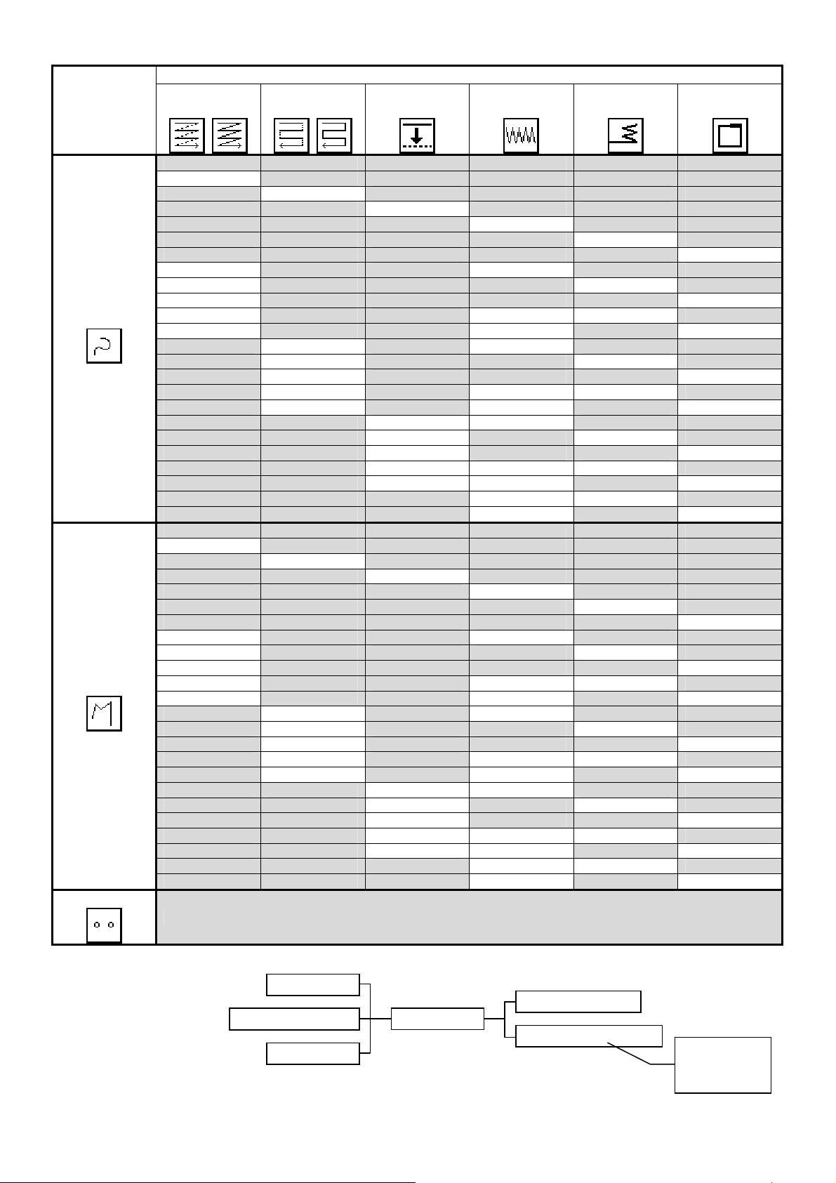
Basic input
Multiple
Reverse
multiple
Application input
Offset
Zigzag
Start/end
back tacking
Overlap back
tacking
Curve
Broken line
Point
Combined pattern
○
○
○
○
○
○
○ ○
○ ○
○ ○
○ ○ ○
○ ○ ○
○ ○
○ ○
○ ○
○ ○ ○
○ ○ ○
○ ○
○ ○
○ ○
○ ○ ○
○ ○ ○
○ ○
○ ○
○
○
○
○
○
○
○ ○
○ ○
○ ○
○ ○ ○
○ ○ ○
○ ○
○ ○
○ ○
○ ○ ○
○ ○ ○
○ ○
○ ○
○ ○
○ ○ ○
○ ○ ○
○ ○
○ ○
(Combination inputs with application inputs are not possible.)
Multiple
Start/end tacking
Reverse multiple
Offset
One of the three can be selected. One of the two can be selected.
Zigzag
Overlap back tacking
Possible only
if the pattern
is closed.
[9] - 2
Page 71
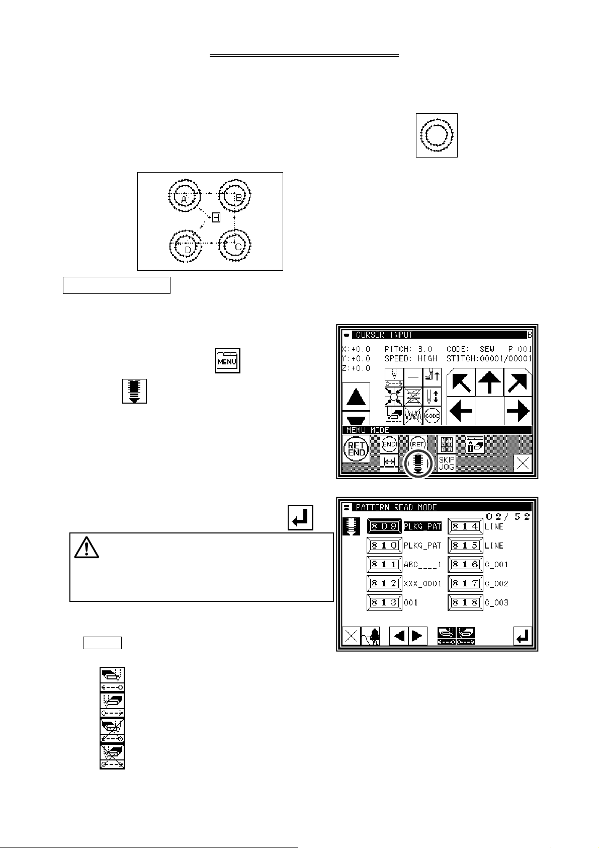
[10] Call-up function
In the sewing data input mode, you can call up the sewing data from the internal memory, and can combine
the called-up data with the currently-created data to create a new sewing data. You can determine whether
the first and final feed data should be deleted.
[Example of call-up function]
To create the following sewing data, preliminarily create the double circle data ( ), and then use the
feed data and call-up functions.
Operation details
(1)Creation of data on feed data from home position H to point A
(2)Display of call-up screen
►
Press the data entry mode .
►
Press in the menu.
(3)Selection of call-up data
►
Select data to be called up, and then press .
Caution
move in accordance with the called-up data.
If the needle is lowered, be careful not to get
injured.
Memo After calling up "feed" data, you can modify
the original "feed" data as follows
The work holder will automatically
:
The feed data at the sewing start point can be deleted.
:
The feed data at the sewing end point can be deleted.
:
The feed data at the sewing start point can be left undeleted.
:
The feed data at the sewing end point can be left undeleted.
(4)For B, C, and D, call up the data in the same way, and complete the data.
[10] - 1
Page 72
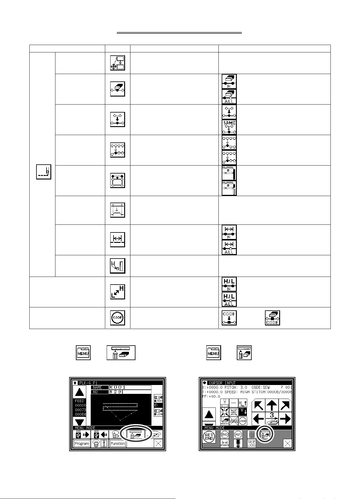
[11] Modification mode
1.Main modification mode functions
Function icon Details Details setting
Modifying the
stitching start
position ([11]-5)
The stitching start position
moves.
-
Deleting a stitch
Adding a stitch
Modifying the
stitch position
Stitch
Moving a block
Modifying a
block
Modifying stitch
length
([11]-7)
([11]-11)
([11]-15)
([11]-19)
([11]-23)
([11]-39)
Designated No. of Stitches
Deletes the designated stitch.
Data for one stitch is added at
designated position
The position of the stitch is
modified
Data in a designated range is
moved.
The area between two points
to be modified is modified with
linear, broken line, arc, curve,
zigzag or feed data.
The stitch length in the
designated range is modified.
All After Designated Stitch
One Stitch Addition
Same Stitch Addition
<After modification position>
Fixed
Relative Movement
<Prior/Subsequent data>
Change
Add new stitch in between
Designated distance modification
All After Designated Stitch
-
Modifying material
step
Modifying the stitching
speed
Modifying code data
([11]-43)
([11]-46)
([11]-50)
The presser foot height at the
specified position is modified.
The stitching speed is modified
from the designated stitch.
Code data is added to or
deleted from designated stitch
position.
2.Entering the modification mode
Press and on the
▪
Standard screen to enter the modification
mode.
-
Designated No. of Stitches
All After Designated Stitch
Add Delete
press and in the input mode to
▪
enter the modification mode.
Method that uses standard screen Method that uses data input mode
[11] - 1
Page 73
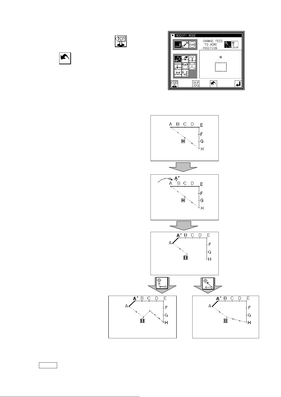
3.Quitting the modification mode
►
After making modifications, press to quit the
modification mode.
(When
will be undone.)
is pressed, the modifications executed last
4.Changing the feed data to home position
►
An example for adding the A' point by adding
one stitch to the original stitching data, as
shown on the left, is explained in this section.
►
Add the A' point as shown on the right.
►
The B point to H point positions will change
when the A' point is added. Thus, the feed
data from the H point to the home position will
also change. The method for changing this
feed data can be selected with the following
icons.
[ Add return ] [ Change return ]
Memo Before modification, check the data. If the data on feed data from the sewing end point to the
home position includes code data, the feed data following the code data will be modified.
[11] - 2
Page 74

5.Confirming on the image screen
If the image display
icon
is pressed in the input mode, modification mode or conversion
mode, the Image screen will open. This Image screen can be used effectively when modifying
(converting) data in the modification (conversion mode), and the data can be modified
(converted) easily.
An example of the Image screen in the modification mode is shown below.
The Image screen can be confirmed after the data modification (conversion) mode is entered, regardless
of before and after modifications made.
▪ When stitching start position is modified
: Closes the Image screen, and opens the
previous screen. (Common for all Image
screens.)
: Indicates the home position.
(Common for all Image screens.)
: Indicates the original stitching start position.
: Indicates the modified stitching start position.
(Current position moved to with the arrow icons.)
<Only the image section is shown in the following explanations.>
▪ Deleting stitches
: Indicates the home position.
(Common for all Image screens.)
: Indicates the stitch deletion start position.
: Indicates the stitch deletion end position.
▪ Modifying the stitch position and adding stitches
: Indicates the home position.
(Common for all Image screens.)
: Indicates the original stitch position/stitch addition
reference position.
: Indicates the modified stitch position/added stitch
position. (Current position moved to with the arrow
icons.)
▪ Moving a block
: Indicates the home position.
(Common for all Image screens.)
: Indicates the block movement start position.
: Indicates the block movement end position.
: Indicates the position after block movement
modification.
[11] - 3
Page 75

▪ Modifying a block (The broken line input data is created with block modification.)
: Indicates the home position.
(Common for all Image screens.)
: Indicates the block modification start position.
: Indicates the block modification end position.
: Broken line transit point 1
: Broken line transit point 2
: Broken line transit point 3
: Broken line transit point 4
: Indicates the current position moved to with the arrow icons.
[11] - 4
Page 76

6.Modifying the stitching start position
[Example] The stitching start position A point in the stitching data will be modified to the B point
as shown below.
Operation details
(1)Selecting the stitching start position movement
►
Enter the modification mode. (Refer to the methods for
entering the modification mode. Page[11]-1)
►
Press Stitch Data Change and Stitching Start
Position Move
►
Press to set the data.
Caution
move to the current stitching start position.
(*1)Take care when the needle is lowered, etc.
.
The work holder will automatically
(2)Moving to the modification position and setting the data
►
Press the arrow icons to move the position to the B
point.
►
Press .
(The sewing start position will be modified.)
Caution
undone, the work holder will automatically return
to the home position. Take care when the needle
is lowered, etc.
When the modifications are
►
If is pressed here, the screen will change to
the previous screen.
(3)Confirming the modified data
►
Quit the modification mode. Press to change to
the Saving mode screen. Press
Standard screen after saving the data.
(When
last will be undone.)
is pressed, the modifications executed
to return to the
[11] - 5
Page 77

(4)Confirming with the Standard screen
AB C
D
►
The stitching start position has been modified.
(*1)
Memo Please note that there is a characteristic explained as follows about " Modifying the stitching
start position “ of the data with the back tacking.
The data of the figure below is the straight line data which puts the start/end back tacking of V
mode. (A fat part is back tacking).
In this case, is sewn in order of A→B→C→D.
Therefore, the actual stitch starting position is "A point." (Starting location of the data origination
(input) is "B point."
Please specify whether to correct the B point because “ Starting location (B) at the data input "
after work holder automatically moves to "Actual stitch starting position (A)" when enters to "
Modifying the stitching start position “
[11] - 6
Page 78

7.Deleting a stitch (Deleting the designated No. of stitches)
[Example] The stitching pattern between the C point and D point in the following type of stitching data will be
deleted.
Operation details
(1)Selecting deletion of stitches
►
Enter the modification mode. (Refer to the methods for
entering the modification mode. Page[11]-1)
►
Press Stitch Data Change and
Stitch Delete
►
Press to open the next screen.
.
(2)Determining the deletion method and the deletion range (start point)
►
Press No. of Stitch Designation .
►
Using Jog , , determine the start point
position (C point).
►
Press when the position has been set.
(3)Determining the deletion range (end point)
►
Using Jog , , determine the end point
position (D point).
►
Press when the position has been set.
Caution
the work holder will automatically return to
the start point. Take care when the needle is
lowered, etc.
When the end point is determined,
[11] - 7
Page 79

(4)Confirming execution
►
Press .
(The stitch will be deleted.)
(5)Confirming after stitch deletion
►
Quit the modification mode. Press to change to
the Saving mode screen. Press
Standard screen after saving the data.
(When
last will be undone.)
is pressed, the modifications executed
to return to the
(6)Confirming with the Standard screen
►
The stitch has been deleted.
[11] - 8
Page 80
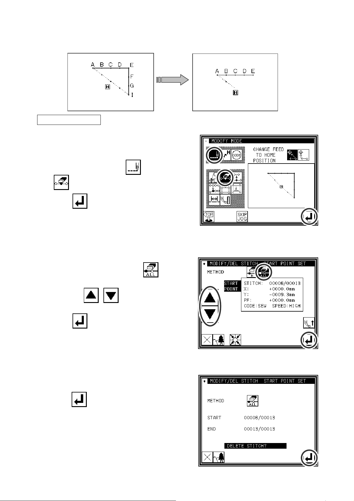
8.Deleting a stitch (Deleting all stitches after the designated position)
[Example] The stitching pattern after the E point in the following type of stitching data will be deleted.
Operation details
(1)Selecting deletion of stitches
►
Enter the modification mode.
►
Press Stitch Data Change and Stitch Delete
.
►
Press to open the next screen.
(2)Determining the deletion method and the deletion range (start point)
►
Press All After Designated Stitch . (All the data
below the specified position will be deleted.)
►
Using Jog , , determine the start point
position (E point).
►
Press when the position has been set.
(3)Confirming execution
►
press .
(All the data below the specified position will be
deleted.)
[11] - 9
Page 81
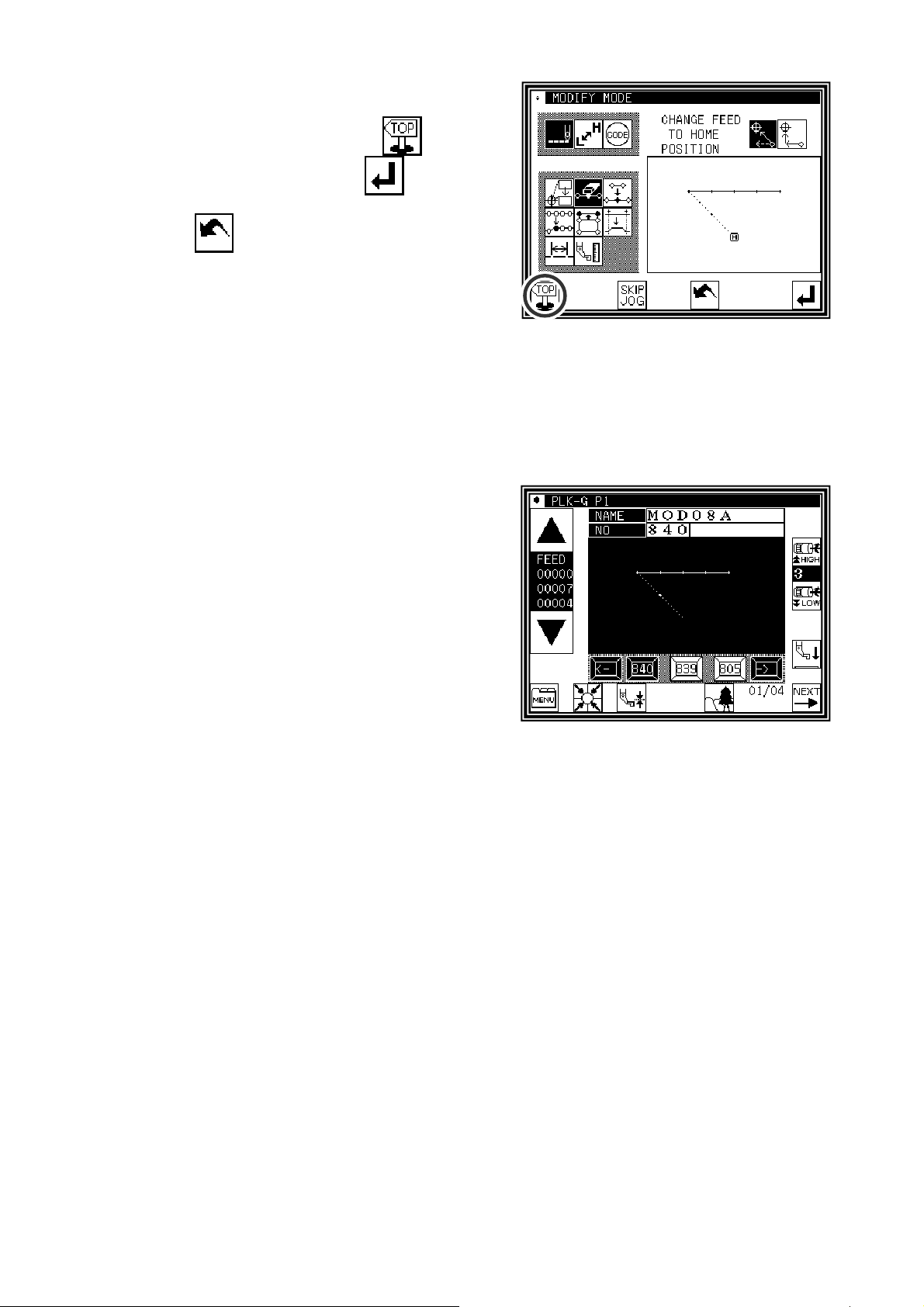
(4)Confirming after stitch deletion
►
Quit the modification mode. Press to change to
the Saving mode screen. Press
Standard screen after saving the data.
(When
last will be undone.)
is pressed, the modifications executed
(5)Confirming with the Standard screen
►
The stitches have been deleted.
to return to the
[11] - 10
Page 82

9.Adding a stitch (Adding one stitch)
[Example] The required stitch length A' will be added to the A point of the following type of stitching
(The maximum stitch length is 20mm (between A and A').)
Operation details
(1)Selecting stitch addition
►
Enter the modification mode.
►
Press Stitch Data Change
and Stitch Add
►
Press to open the next screen.
.
(2)Determining the addition position
►
Using Jog , , determine the position to be
added. Move to the addition position (point A).
►
Press when the position has been set.
(3)Setting the addition method
►
Press One Stitch Addition , and then use the
arrow icons to move and input the stitch position to be
added. (A' point)
►
Press .
(One stitch will be added.)
[11] - 11
Page 83
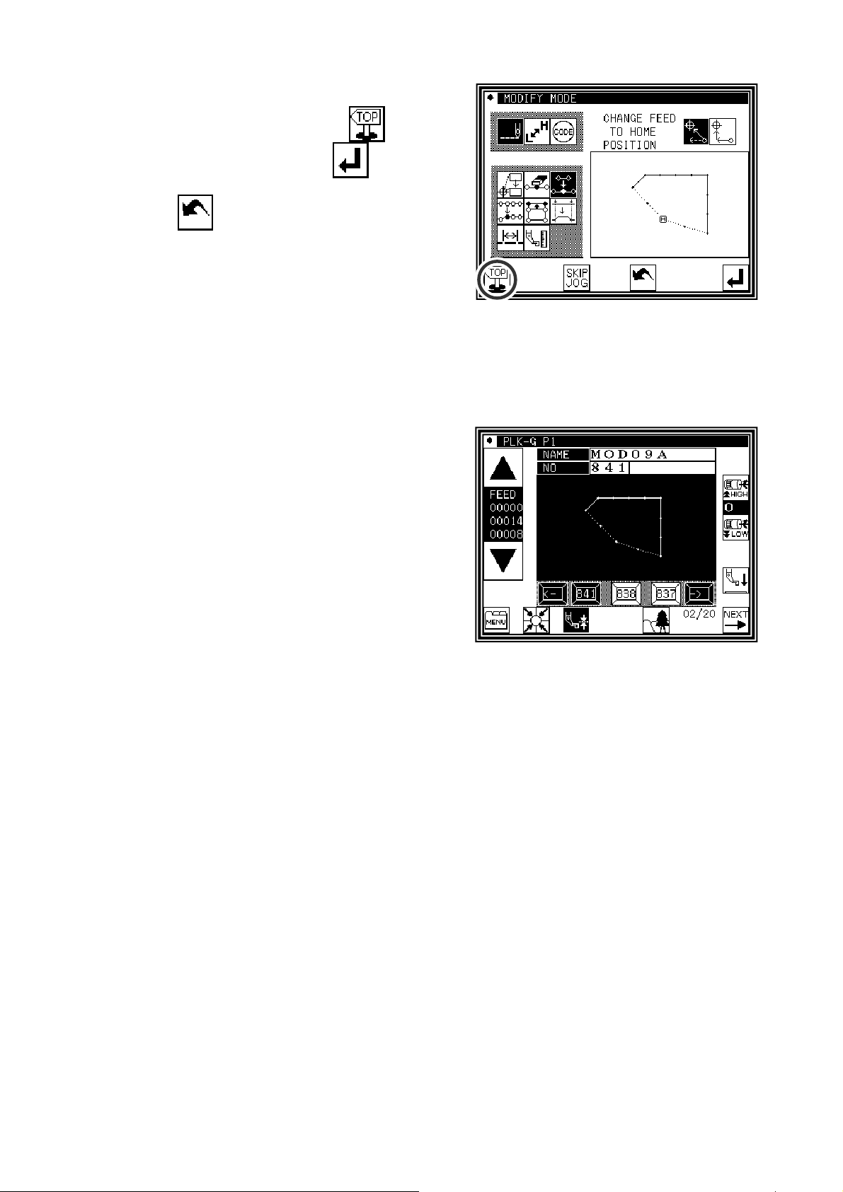
(4)Confirming after stitch addition
►
Quit the modification mode. Press to change to
the Saving mode screen. Press
Standard screen after saving the data.
(When
last will be undone.)
is pressed, the modifications executed
(5)Confirming with the Standard screen
►
One stitch has been added.
to return to the
[11] - 12
Page 84
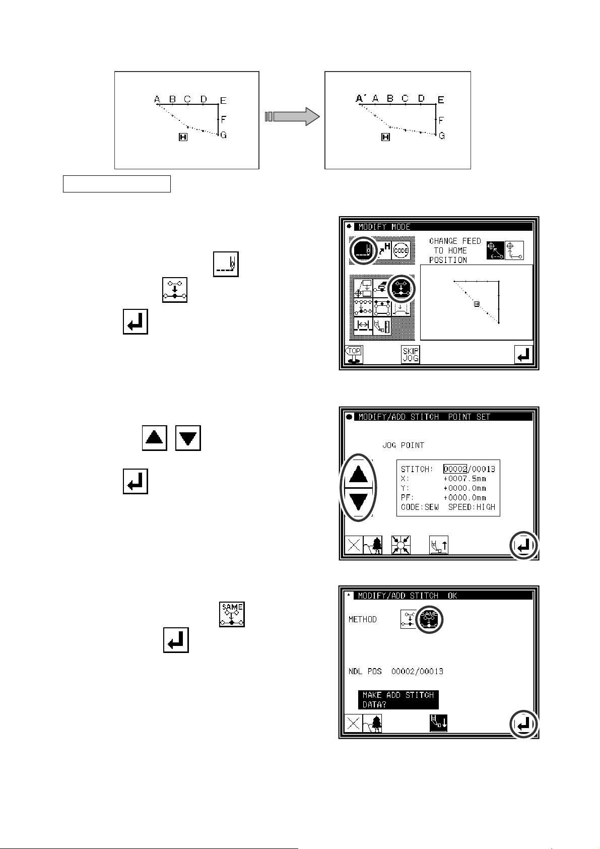
10.Adding a stitch (Adding the same stitch)
[Example] The stitch A' point, the same as A, will be added to the A point of the following type of stitching data.
Operation details
(1)Selecting stitch addition
►
Enter the modification mode.
►
Press Stitch Data Change
and Stitch Add
►
Press to open the next screen.
.
(2)Determining the addition position
►
Using Jog , , determine the position to be
added. Move to the addition position (point A).
►
Press when the position has been set.
(3)Setting the addition method
►
Press Same Stitch Addition ,
and then press
(The same stitch will be added.)
.
[11] - 13
Page 85

(4)Confirming after stitch addition
►
Quit the modification mode. Press to change to
the Saving mode screen. Press
Standard screen after saving the data.
(When
last will be undone.)
is pressed, the modifications executed
(5)Confirming with the Standard screen
►
The same stitch has been added.
to return to the
[11] - 14
Page 86
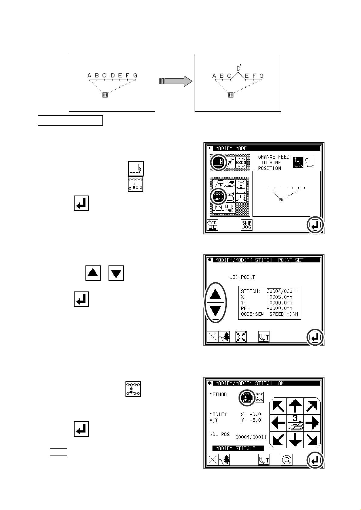
11.Modifying the stitch position (Position of subsequent data
fixed)
[Example] The D point in the following type of stitching data will be moved.
Operation details
(1)Selecting stitch position modification
►
Enter the modification mode.
►
Press Stitch Data Change
and Stitch Position Modify
►
Press to open the next screen.
.
(2)Determining the modification position
►
Using Jog , , determine the position to
be modified.(D point)
►
Press when the position has been set.
(3)Setting the modification method and modification amount
►
To set the method, press .
(pattern data after modification stitch fixed), and move
to the modification position (point D') using the arrow
mark icons.
►
Press .
The stitch position will be modified.
(
Memo Move the stitch length so that it is within the
range of 20mm at the maximum.
)
[11] - 15
Page 87
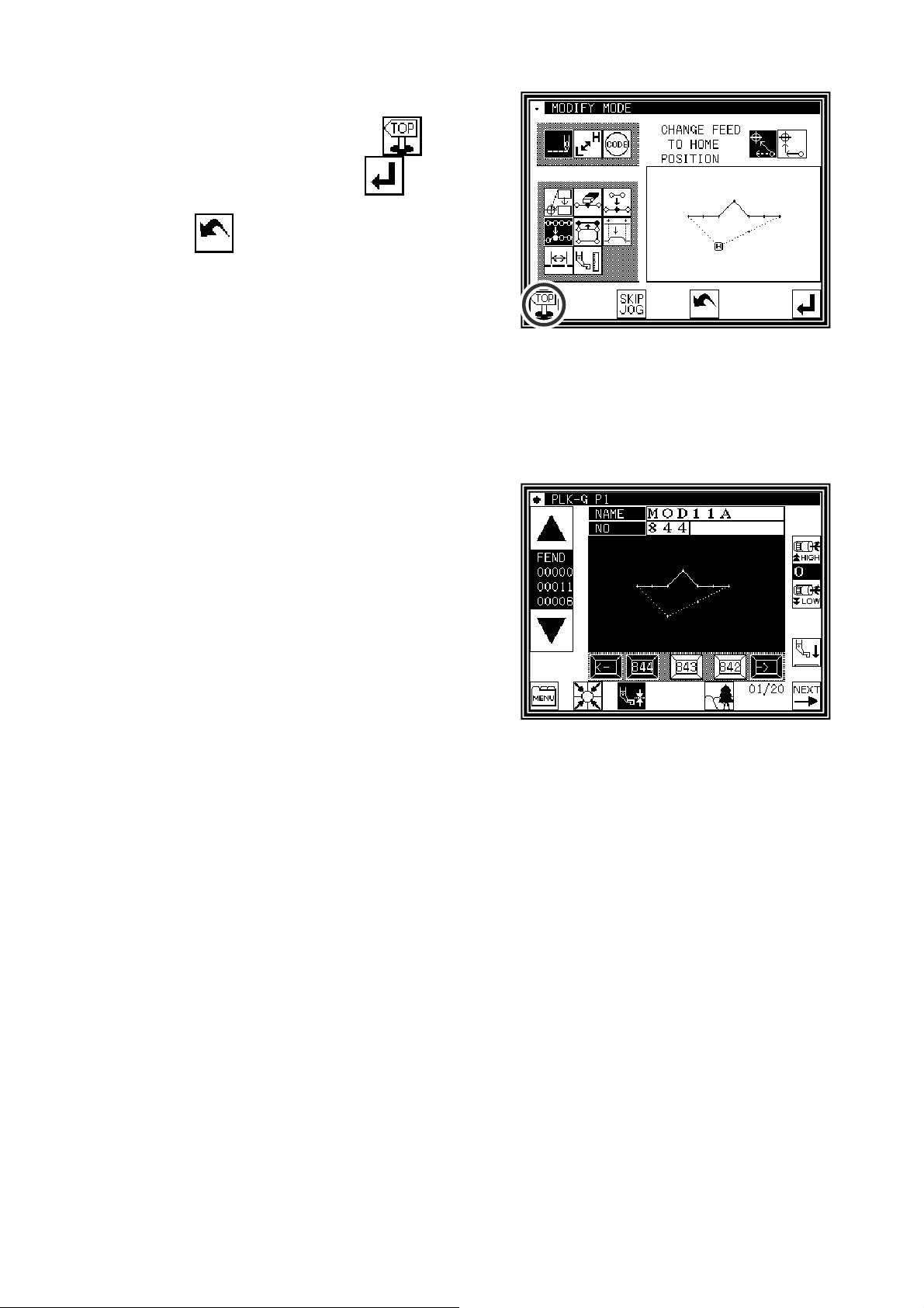
(4)Confirming after modification
►
Quit the modification mode. Press to change to
the Saving mode screen. Press
Standard screen after saving the data.
(When
last will be undone.)
is pressed, the modifications executed
(5)Confirming with the Standard screen
►
The stitch position has been modified.
to return to the
[11] - 16
Page 88

12.Modifying the stitch position (Subsequent data position moved)
[Example] The C point in the following type of stitching data will be moved. (The D, E, F and G points will
move)
Operation details
(1)Selecting stitch position modification
►
Enter the modification mode.
►
Press Stitch Data Change and
Stitch Position Modify
►
Press to open the next screen.
.
(2)Determining the modification position
►
Using Jog , , determine the position to be
modified.(C point)
►
Press when the position has been set.
(3)Setting the modification method and modification amount
►
To set the method, press .
(pattern data after modification stitch moved), and
Move to the modification position (point C') using the
arrow mark icons.
►
Press .
The stitch positions will be modified.
(
)
Memo Move the stitch length so that it is within the
range of 20mm at the maximum.
[11] - 17
Page 89

(4)Confirming after modification
►
Quit the modification mode. Press to change to
the Saving mode screen. Press
Standard screen after saving the data.
(When
last will be undone.)
is pressed, the modifications executed
(5)The stitch position has been modified.
►
The stitch positions have been modified.
to return to the
[11] - 18
Page 90

13.Moving a block (Changing the prior/subsequent data)
[Example] The section between the D point and E point of the following type of stitching data will be moved to
the D' point to E' point. At this time, the data prior to and after the D' point to E' point will be changed.
Operation details
(1)Selecting block movement
►
Enter the modification mode.
►
Press Stitch Data Change
and Block Move
►
Press to open the next screen.
.
(2)Determining the block modification range (start point)
►
Using Jog , , determine the start point
position.(D point)
►
Press .
(3)Determining the block modification range (end point)
►
Using Jog , , determine the end point
position.
►
Press .
Caution
When the end point is determined,
the presser will automatically return to the start
point. Take care when the needle is lowered, etc.
[11] - 19
Page 91
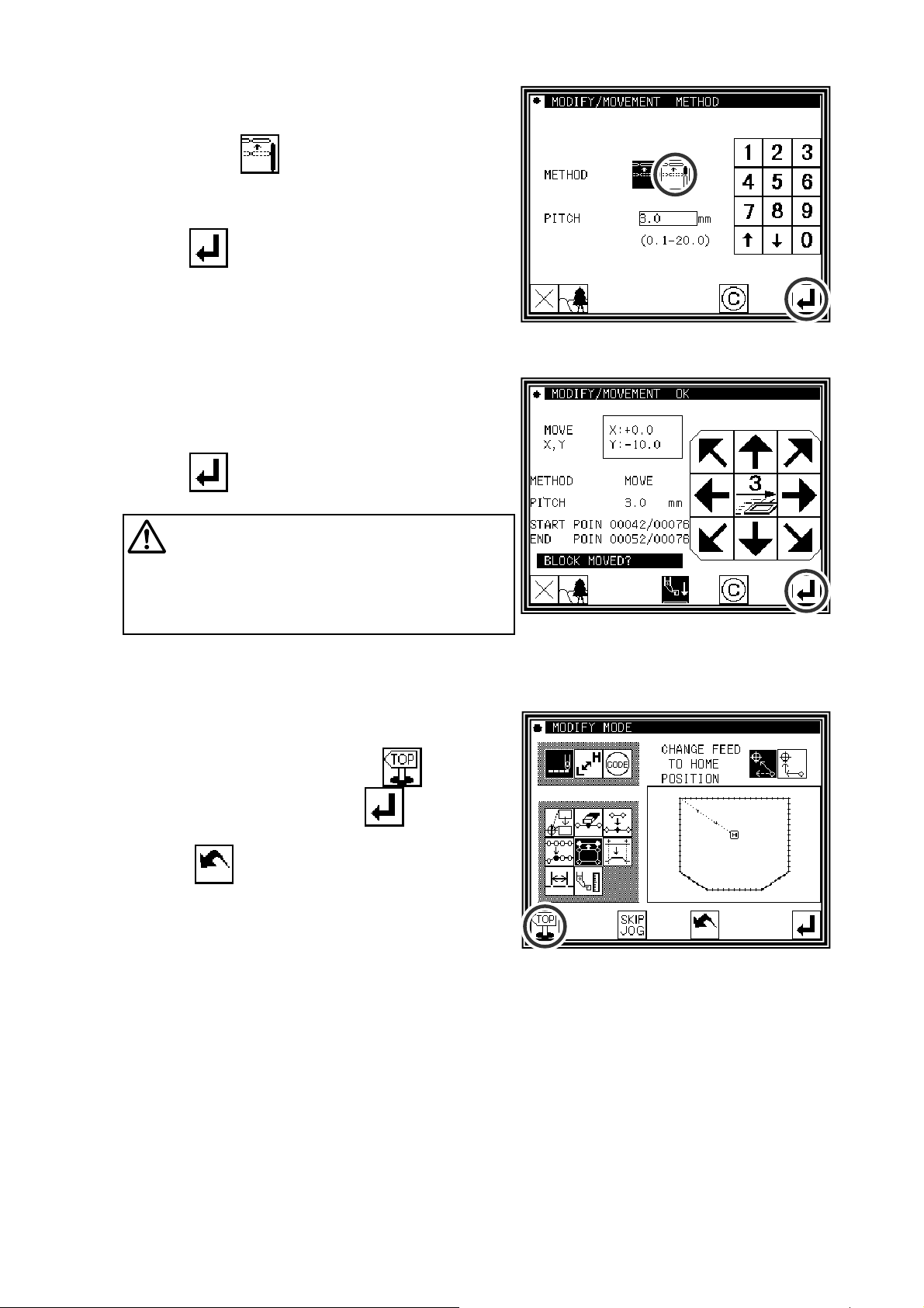
(4)Setting the movement method and stitch length
►
Set the movement method. Press Prior/Subsequent
Data Change
►
Set the stitch length.
(Set to 3.0mm for this example.)
►
Press .
.
(5)Determining the movement amount
►
Using the arrow icons, determine the movement
amount.(Move to the position (point D').)
►
Press
(The block position will be modified.)
Caution
work holder will return to the start point of the
section being modified; in this case the start point
(A point) of the broken line input.)
Take care when the needle is lowered, etc.
The work holder will move. (The
(6)Confirming after modification
►
Quit the modification mode. Press to change to
the Saving mode screen. Press
Standard screen after saving the data.
(When
last will be undone.)
is pressed, the modifications executed
to return to the
[11] - 20
Page 92

14.Moving a block (Adding new data to the prior/subsequent data)
[Example] The section between the D point and E point of the following type of stitching data will be moved to
the D' point to E' point. At this time, new data will be added prior to and after the D' point to E' point. (the
D point to D' point and the E point to E' point)
Operation details
(1)Selecting block movement
►
Enter the modification mode.
►
Press Stitch Data Change
and Block Move
►
Press to open the next screen.
.
(2)Determining the block modification range (start point)
►
Using Jog , , determine the start point
position.(D point)
►
Press .
(3)Determining the block modification range (end point)
►
Using Jog , , determine the end point
position.(E point)
►
Press .
Caution
When the end point is determined,
the presser will automatically return to the start point.
Take care when the needle is lowered, etc.
[11] - 21
Page 93

(4)Setting the movement method and stitch length
►
Set the movement method.
Press Add New Stitch To Prior/Subsequent Data
.
►
Set the stitch length.
(Set to 3.0mm for this example.)
►
Press .
(5)Determining the movement amount
►
Using the arrow icons, determine the movement
amount. (Move to the position (point D').)
►
Press .
(The block position will be modified.)
Caution
The presser will move.
(The presser will move to one stitch before the D
point.) Take care when the needle is lowered, etc.
(6)Confirming after modification
►
Quit the modification mode. Press to change to
the Saving mode screen. Press
to return to the
Standard screen after saving the data.
(When
last will be undone.)
is pressed, the modifications executed
[11] - 22
Page 94

15.Modifying a block 1 (Linear input)
[Example] The section between the A point and B point of the following type of stitching pattern will be
modified to a linear line.
Operation details
(1)Selecting block modification
►
Enter the modification mode.
►
Press Stitch Data Change
and Block Modify
►
Press to open the next screen.
.
(2)Selecting the input type and the stitch length
►
Press Linear .
►Set the stitch length. (Set to 3.0mm for this example.)
►
Press to set the data.
(3)Determining the block modification range (start point)
►
Using Jog , , determine the start point
position.(A point)
►
Press .
[11] - 23
Page 95

(4)Determining the block modification range (end point)
►
Using Jog , , determine the end point
position.(B point)
►
Press .
Caution
When the end point is determined,
the work holder will automatically return to the
start point. Take care when the needle is
lowered, etc.
(5)Confirming the data creation
►
Press .
(The block position will be modified.)
(6)Confirming the modified data
►
Quit the modification mode. Press to change to
the Saving mode screen. Press
Standard screen after saving the data.
(When
last will be undone.)
is pressed, the modifications executed
to return to the
[11] - 24
Page 96
[Memo] 1. When arc modification is selected for block modification: Arc modification will be executed just
by indicating one point in the designated range.
2. When linear modification is selected for block modification: The modification range will be
connected with linear lines.
3. If the block to be modified contains code data, the code data will be deleted.
4. The block modification start point and end point are explained below.
■For modification other than feed data modification
The start point can be designated when the stitch is stitching data.
The end point can be designated when the section before the stitch is stitching data.
(Refer to following illustration.)
(The data between the start point and end point is irrelevant. However, the feed data
between the start point and end point will be changed to stitching data.)
Feed
without
stitching
Stitching
1
↓
Feed
without
stitching
2
3
4
↓
↓
↓
Stitching
5↓6
↓
Start point End point Designation validity
1 - 2 Valid (OK)
1 - 3 Valid (OK)
1 - 4 Invalid (NG) ... Prior section is feed data
1 - 5 Invalid (NG) ... Prior section is feed data
1 - 6 Valid (OK)
■For feed data modification
The start point can be designated when the stitch is stitching data or feed data.
The end point can be designated when the section before the stitch is stitching data or feed
data.
(The data between the start point and end point is irrelevant.)
[11] - 25
Page 97
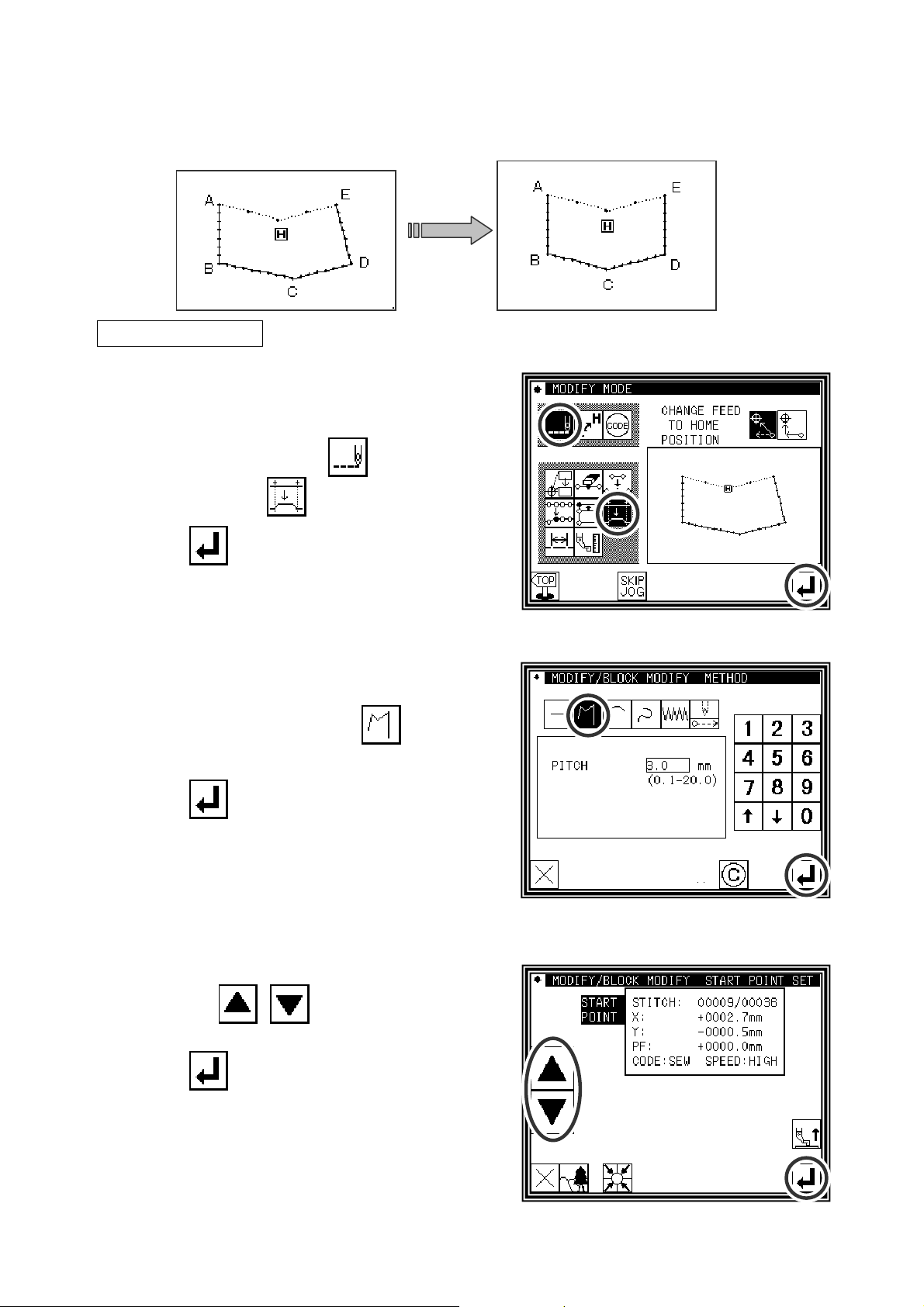
16.Modifying a block 2 (Broken line, arc, curve input)
Methods for designating the modification position with the jog icons.
the modification origin data as a reference.)
(This is handy when using
[Example] The C point and D point in the following type of data are each modified to the C' point and D' point.
´
´
Operation details
(1)Selecting block modification
►
Enter the modification mode.
►
Press Stitch Data Change
and Block Modify
►
Press to open the next screen.
.
(2)Selecting the input type and the stitch length
►
In this case, press Broken Line .
►Set the stitch length. (Set to 3.0mm for this example.)
►
Press to set the data.
(3)Determining the block modification range (start point)
►
Using Jog , , determine the start point
position.(B point)
►
Press .
[11] - 26
Page 98
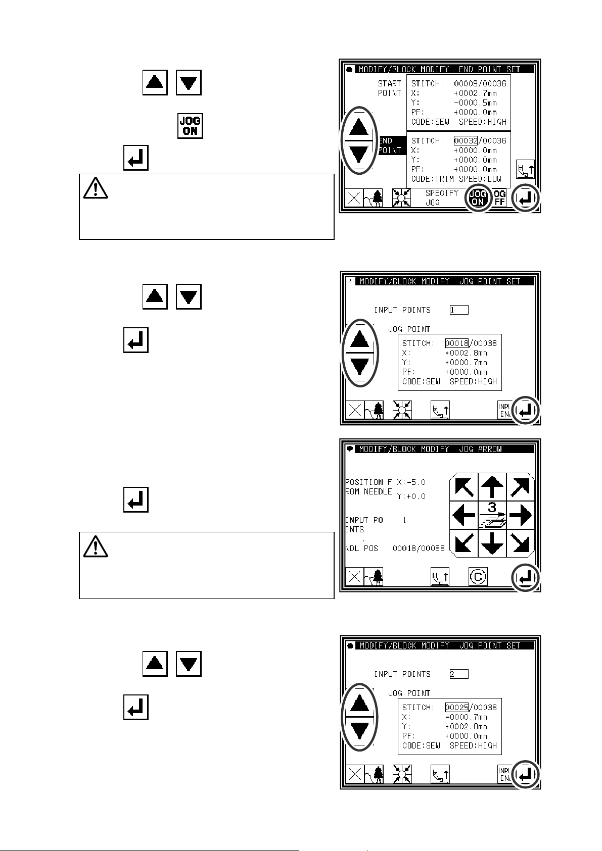
(4)Determining the block modification range (end point)
►
Using Jog , , determinethe end point
position.(E point)
►
Press Jog Validity .
►
Press .
Caution
When the end point is determined,
the work holder will automatically return to
the start point. Take care when the needle is
lowered, etc.
(5)Moving and setting the modification origin jog position
►
Using Jog , , move to the position to be
modified. (C point in this example.)
►
Press .
(6)Moving from the modification origin jog position to
the modification position, and setting the data
►
Press the arrow icons and modify the position. (Move
to the C' point in this example.)
►
Press .
Caution
The work holder will automatically
return to the modification origin jog position
(Needle position specified at (5.)).
Take care when the needle is lowered, etc.
(7)Moving and setting the modification origin jog position
►
Using Jog , , move to the position to be
modified. (D point in this example.)
►
Press .
[11] - 27
Page 99
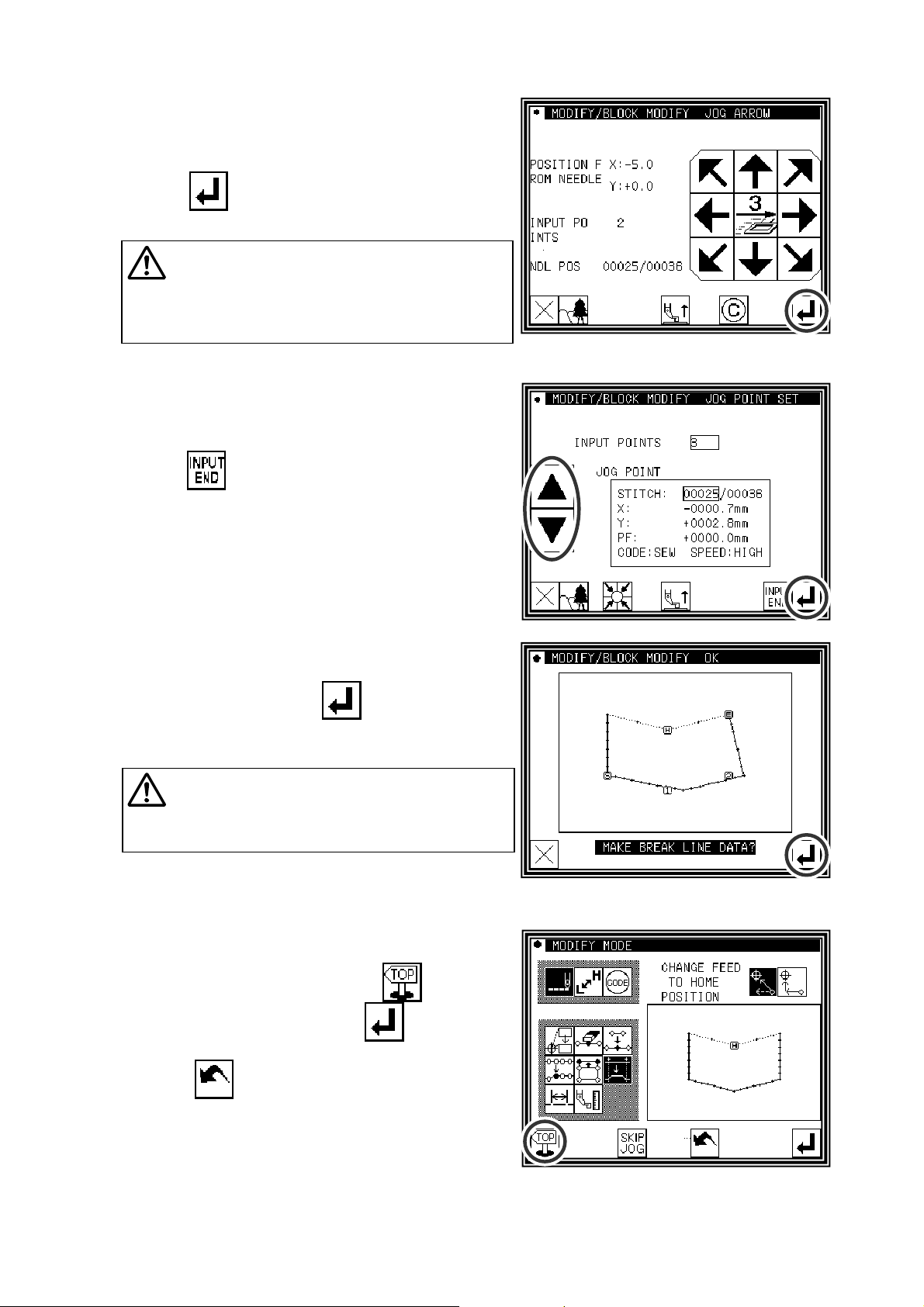
(8)Moving from the modification origin jog position to
the modification position, and setting the data
►
Press the arrow icons and modify the position. (Move
to the D' point in this example.)
►
Press .
Caution
The work holder will automatically
return to the modification origin jog position
(Needle position specified at (5.)).
Take care when the needle is lowered, etc.
(9)Quitting position modification
►
After determining all modification positions,
press
.
(10)Confirming the data creation
►
To create the data, press
(The block position will be modified.)
Caution
The work holder will automatically
return to the start point. Take care when the
needle is lowered, etc.
(11)Confirming the modified data
►
Quit the modification mode. Press to change to
the Saving mode screen. Press
Standard screen after saving the data.
(When
last will be undone.)
is pressed, the modifications executed
to return to the
[11] - 28
Page 100
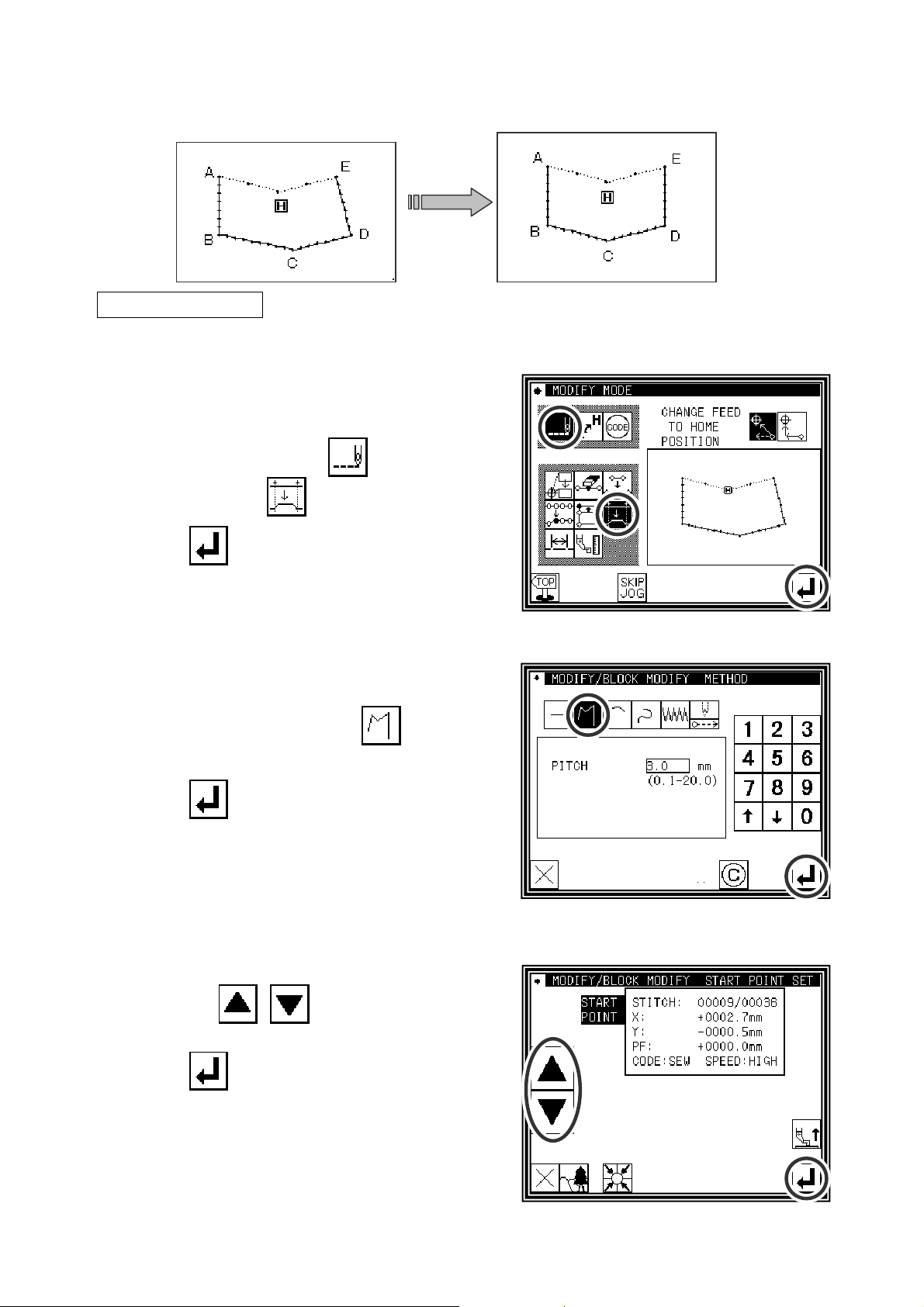
Designating the modification position without using jog icons
■
(Handy for newly creating data.)
[Example] The C point and D point in the following type of data are each modified to the C' point and D' point.
´
´
Operation details
(1)Selecting block modification
►
Enter the modification mode.
►
Press Stitch Data Change
and Block Modify
►
Press to open the next screen.
.
(2)Selecting the input type and the stitch length
►
In this case, press Broken Line .
►Set the stitch length. (Set to 3.0mm for this example.)
►
Press to set the data.
(3)Determining the block modification range (start point)
►
Using Jog , , determine the start point
position.(B point)
►
Press .
[11] - 29
 Loading...