

Page 1

INDUSTRIAL SEWING MACHINE
MODEL
PLK-G-CU-20
TECHNICAL MANUAL
Control Unit
A180E604P09
Page 2

Page 3

Contents
[1] For safe use _______________________________________________ [1]-1
[2] Precautions for use _________________________________________ [2]-1
[3] Installation ________________________________________________ [3]-1
[4] Names of each part, wiring and grounding______________________ [4]-1
[5] Confirmation_______________________________________________ [5]-1
[6] Initial Settings of System Software (Model/Language Settings)_____ [6]-1
[7] Timing chart _______________________________________________ [7]-1
[8] Customized input/output ____________________________________ [8]-1
[9] Input/Output signal _________________________________________ [9]-1
[10] What happened? Could it be an error? ________________________ [10]-1
[11] Several power supply ______________________________________ [11]-1
[12] Unit wiring diagram ________________________________________ [12]-1
[13] Connectors layout _________________________________________ [13]-1
[14] Pin number of connectors __________________________________ [14]-1
[15] Wiring diagram inside control box____________________________
[16] Specifications_____________________________________________ [16]-1
[15]-1
- 1 -
Page 4

Thank you for purchasing the Mitsubishi industrial sewing machine PLK-G Series.
Please read this technical manual before starting to ensure correct and long-term
use.
* The contents of this manual may not be reproduced in part or whole.
* The contents of this manual are subject to change without notice.
* An utmost effort has been made to cover all points of operation in this manual.
Contact Mitsubishi if you have any questions regarding the contents.
COPYRIGHT(C)2012 MITSUBISHI ELECTRIC CORPORATION
- 2 -
Page 5

[1] For safe use
■ For safe use
Always observe the following matters to safely use the Mitsubishi industrial electronic sewing machine PLK-G
Series.
Before starting
Before using this control unit, read all of the technical manuals carefully, and correctly use the unit
following the manual. Also read the "Mitsubishi Industrial Sewing Machine Technical Manual <Sewing
Machine Head>" for details on the general configuration and sewing machine head.
Application and purpose
This control unit is designed to drive and control the Mitsubishi industrial electronic sewing machine
PLK-G Series. Do not use this control unit for other applications or purposes. Do not use this control unit
until it has been confirmed that safety measures have been accurately taken for the installed electronic
sewing machine head section.
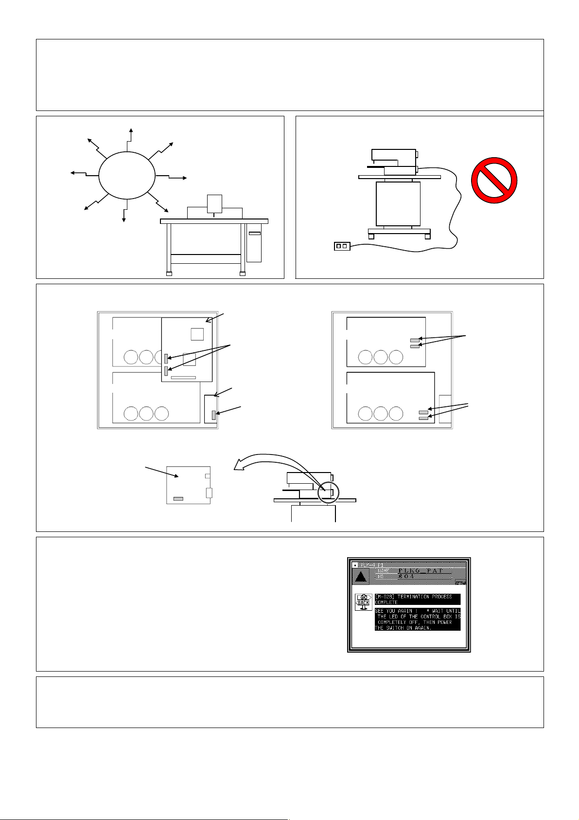
Working environment
Please use this control unit in the industrial setting only. And do not use this control unit in the following
type of environment.
(1) Power voltage
* Where the voltage fluctuation exceeds ±10% of the rated voltage.
* Where the specified power capacity (refer to technical manual [Control unit] page [4]-2 “5. Power
capacity”) cannot be ensured.
(2) Magnetic noise
* Where strong fields or magnetic fields are generated, such as near a high-output high frequency
oscillating machine or high frequency welder.
(3) Temperature and humidity
* Where the ambient temperature is 35°C or more and 5°C or less.
* Where the unit will be subject to direct sunlight, or outdoors.
* Near sources of heat, such as heating appliances.
* Where the relative humidity is 45% or less, or 85% or more, and where dew may condense.
(4) Atmosphere
* In an atmosphere containing dust or corrosive gases, etc.
* In a flammable gas or explosive environment.
(5) Vibration
* If excessive vibration could occur when installed on the sewing machine, separately install the
control box.
■ Installation
Control box
Correctly install the control box according to this manual.
Accessories
Always disconnect the control unit from the main power supply before installing the accessories listed in
this manual. (Turn the power switch OFF, and disconnect the plug from the socket (power supply line).)
Cable
(1) Lay the connection cables so that excessive force will not be applied during operation. Do not
excessively bend the cables.
(2) Cables laid near operating machine sections must be separated by at least 25mm.
(3) Before connecting the power cable to the control box, confirm that the power voltage matches the
specifications given on the control box's rating nameplate and factory shipment voltage nameplate.
Connect the cable to the indicated positions, and then supply the power. When using a power unit,
connect the cable to the power unit and supply the power. In addition, when using a power unit,
confirm that the power voltage matches the specifications given on the power unit's rating nameplate.
Turn the power switch OFF before making any connections.
Grounding
Always ground the power cord's grounding wire.
Enclosed units and accessories
Connect the electrical enclosed units and accessories only to the positions indicated in the manual.
[1] - 1
Page 6
Removal
(1) Always turn the power switch OFF and disconnect the plug from the socket (power supply line) before
removing the control box.
(2) Do not pull out the cord when disconnecting the plug. Always hold the plug receptacle when
disconnecting the plug.
(3) Note that a high voltage is applied inside the control panel, so always turn the power OFF and wait
at least ten minutes before opening the control box cover.
■ NOTICE CONCERNING MARKING
(1) Electronic sewing machine PLK-G series are applied to CE conformity marking by installing the
exclusive device [PLK-G-CE].
When the products are used in the EU region, these devices are necessary to be installed.
(2) Electronic sewing machine should be use limited to the industrial areas even though above-mentioned
countermeasure is done.
[Warning] Use in residential areas may cause interference.
■ Maintenance, inspection and repairs
(1) Follow this manual when carrying out maintenance or inspections related to this control unit.
(2) This unit must be repaired, serviced and inspected only by a worker that has received special training.
(3) Always turn the power OFF before replacing the needle or bobbin, etc., on the head.
(4) Use genuine replacement parts for repairs and maintenance.
■ Other safety measures
(1) Keep fingers away from all moving machine parts (especially around the sewing machine needle,
etc.).
(2) Never drop the control unit, or place objects in the clearances.
(3) Do not operate the sewing machine without the protective parts such as the cover, or protection
devices such as the safety breaker.
(4) If any damage is observed in the control unit, if the unit does not operate correctly, or if the operation
is suspicious, always suspend operation. Only operate the machine after the supervisor has adjusted,
repaired or inspected the machine.
(5) The user must not make improvements or changes without instruction from Mitsubishi.
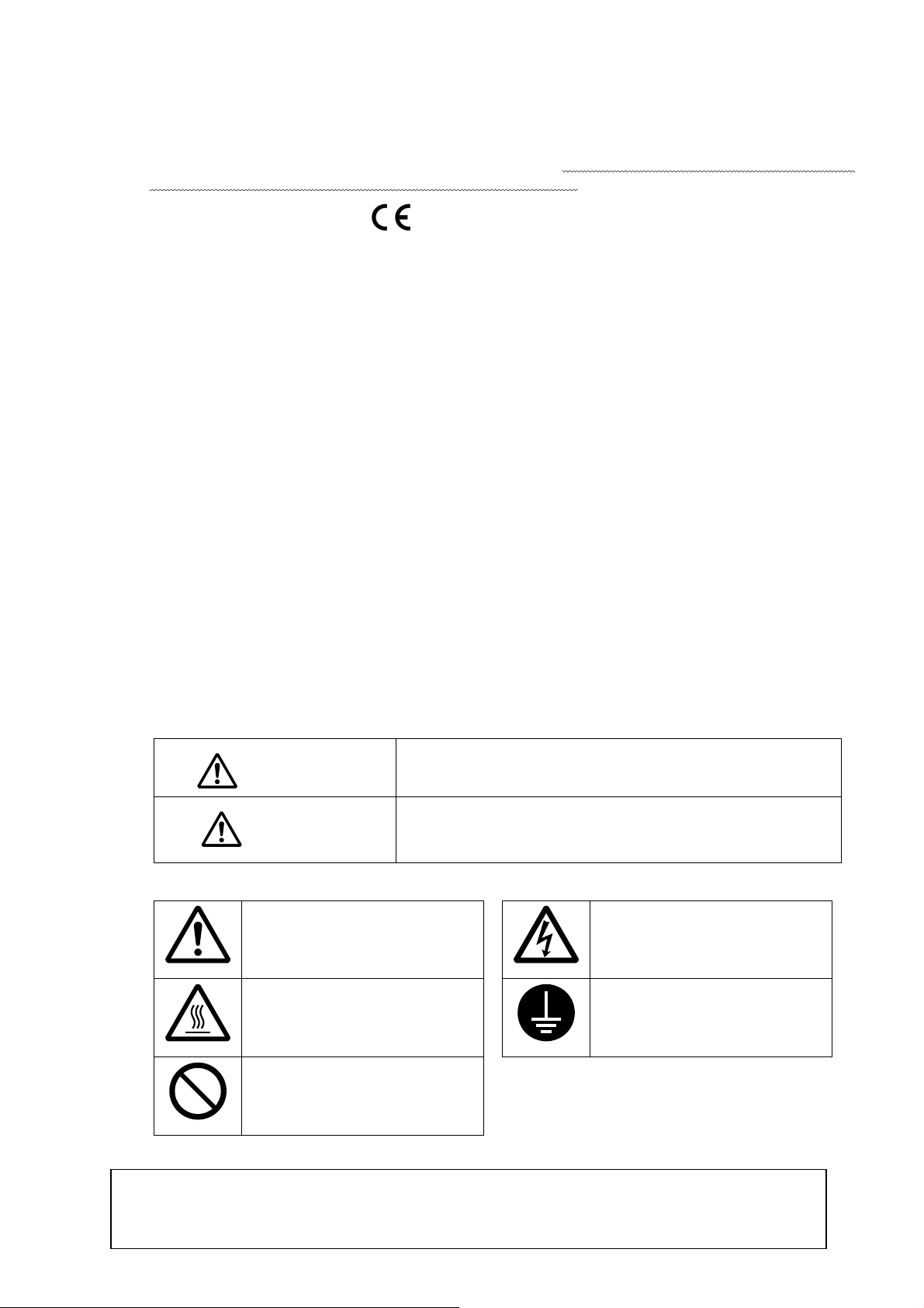
■ Caution displays and danger displays
(1)In this manual, the dangers and danger levels that arise with incorrect handling are classified using the
following displays.
The warning display shows that incorrect handling can lead to
Warning
Caution
(2)The meanings of these symbols are as follows.
This symbol indicates that the
instructions must be followed.
This symbol indicates hot
temperature requiring caution.
This symbol indicates a
prohibited action.
death or serious injuries.
The caution display shows that incorrect handling can lead to
injuries or damages to your house, household goods, and
others.
This symbol indicates an
electrical hazard or caution
(electric shock caution).
This symbol indicates that
ground wire connection is
required.
* Always deliver this manual to the end user.
* Store this manual nearby where it can be referred to when necessary.
[1] - 2
Page 7

[2] Precautions for use
Warning
1. Do not place foot on the foot switch when turning the power ON.
3. Do not inspect the control circuit with a tester.
Control circuit
The tester voltage could be applied on the semiconductor
parts, and cause damage.
5. Always ground the grounding wire.
Power supply
Green
(Green/yellow)
Always ground the provided grounding wire
(green(green/yellow)).
7. A high voltage is applied inside creating a hazardous state, so
always turn the power OFF and wait ten minutes before opening
the cover.
High voltage risk
2. Always turn the power OFF when leaving the sewing machine.
4. Always turn the power switch OFF before tilting the sewing
machine head, replacing the needle, or passing thread through the
needle.
6. Do not use excessive wiring.
8. Radiation fins and other parts may be hot. Do not touch the parts.
[2] - 1
Page 8
)
)20A
)20A
)15A
9. The sewing machine will coast to a stop when the power is turned OFF or a power failure occurs during sewing machine operation.
10. Always align the connector shape and direction, and securely insert the connector.
11. If the position detector's connector dislocates, or the sewing machine is completely locked, the motor will be turned OFF automatically for a
set time to prevent burning. (Note that the motor may not turn OFF if there is incomplete locking or an overload.) When the fault has been
recovered, turn the power OFF and ON once to resume normal operation. The same type of operation will take place if a detector fault or
disconnection occurs.
12.Use the machine away from strong noise sources such as high
frequency welders.
14. If the fuse blows, remove the cause, and replace the blown fuse with one having the same capacity.
Noise
PLK-G3-CPU
13. When connecting the external switch to an optional connector,
etc., keep the signal wire as short as possible. A long wire could
cause malfunctions.
Use a shielded wire for the signal wire when possible.
XC-G2-2B-PLK
PLK-G2-PMD
(View from the front with cover removed) (View from the front
15. Attention when power supply is turned on again
Please make sure not to turn on the power supply switch until after
the LED on the front panel of the control box has completely turned off.
(Please do not turn on the power supply again while displaying
the screen of the operation panel.)
* Please note that if power supply is turned on again while LED still turns on,
clamp outputs (O4, O5 port) may go down.
16. When the value of the sewing area limit is changed or the limit setting is deactivated, note the collision and
with the cover and CPU removed)
fuse(one fuse)
Solenoid board located
on back of machine head
2.5Afuse(two fuses
PLK-G2-PMM
8Afuse(one fuse
XC-G2-2B-PLK
PLK-G2-PMD
fuse(two fuses
fuse(two fuses
take care safely.
Also when using it outside the range where the mechanism can be operated, it can not assume the responsibility for
all problems caused by it.
[2] - 2
Page 9
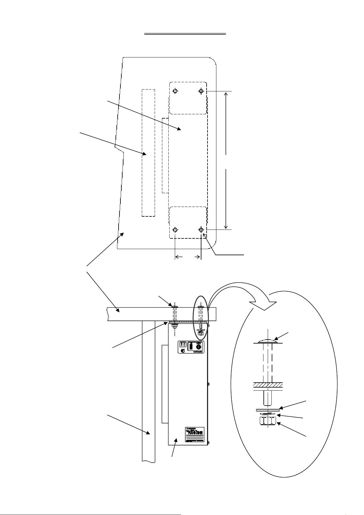
r
1. Installing the control box
control box
Top view of control box
installation area
Front view of control box
installation area
Leg
Top plate
Damper
cushion
Leg
[3] Installation
●Insert the four bolts into the holes
on the top plate and install the
control box.
427
4-Ø9
80
Installation bolt
(Fix at four positions)
Installation bolt
(M8×60)
Washer
Spring
washe
Nuts
control box
[3] - 1
Page 10
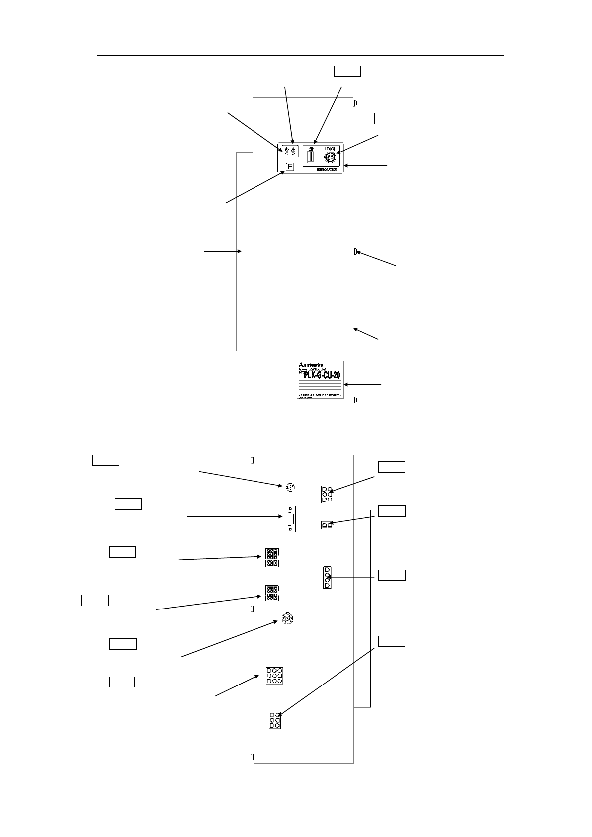
[4] Names of each part, wiring and grounding
p
r
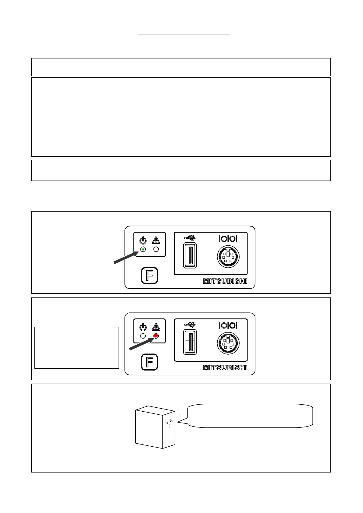
1.Front side
Power
LED(green)
Function button
Heat sink
Warning
LED(red)
CONR
USB(TYPE A)
with Protective cap
CONS
RS-232C(MINI DIN)
with Protective cap
anel
Front
Cover installation screw
(M4 screw)
2.Back side
CONA
Operation panel
(Connect to Operation panel)
CONG
XY axis encoder
(Connect to XY axis stepping motor)
CONE
Various solenoids
(Connect to sewing machine
head section)
CONF
Spindle encoder
(Connect to spindle servo
motor)
Cove
Rating plate
CONB
Power supply
(Connect to power switch box)
CONC
DC power for solenoid
(Connect to sewing machine head
section)
COND
Spindle servo motor
(Connect to spindle servo motor)
CONH
Foot switch
(Connect to foot switch)
CONJ
XY axis stepping motor
(Connect to sewing machine
head stepping motor)
[4] - 1
CONK
PF axis stepping motor
(Connect to sewing machine head
PF axis stepping motor)
Caution: Be sure to connect all connectors
before turning ON the power.
Connect each connector fully to
ensure sufficient contact. Refer to
“[12] Unit Wiring Diagram.”
Page 11

3. Connecting the power connector
p
r
Control box
4. Connecting the 3-phase power supply
3-phase power supply R-phase S-phase T-phase
Push-button switch cord
Red(black)
White(brown)
Black(blue)
Green(green/yellow)
Control box
Power connector (6-pole)
Caution1: Always confirm the connector shape and insertion
Caution2: Please do not bundle the power cable and other
Top plate
owe
orientation and completely insert the power connector
into the control box. Always turn the power OFF before
connecting the connector.
cables together. It may cause of malfunction by the
influence of the power supply noise etc.
Warning
Always connect the green wire to the grounding terminal.
Consult with your electrician for details on the grounding wire.
5. Power capacity
Use a fuse or safety breaker on the power supply.
Power supply Recommended current capacity value
3-phase 200V
10A
6. Using the 3-phase 200V control box with single-phase 200 to 220V
Connect power supply to the "red" and "white" lead wires for the push-button switch.
The black wire is not used, so insulate it by wrapping insulation tape, etc., around it.
Always ground the green grounding wire.
Connect to ground
Connection connector to control box Push-button switch
OFF ON
Do not connect
(Accurately insulate
with tape.)
Green
Red
White
Black
Connect these lead
wires to the power
supply.
[4] - 2
Page 12
[5] Confirmation
1. Before turning the switch ON
(1)Are the power and capacity correct?
(2)Are the connectors correctly inserted? (
* Power connector from push-button switch
* Connector for connection with sewing machine
* Motor connector
* Motor encoder connector
* Foot switch connector
* Other connectors (solenoid, etc.)
(3)Does the hand pulley turn easily?
2. After turning the switch ON
(1)Is the front panel power LED (green) on?
Refer to “[12] Unit Wiring Diagram.”)
(2)Is the front panel warning LED (red) on or flickering?
For actions to be taken
when the warning LED (red)
is on or flickering, refer to
“[10] What Happened?
Could it Be an Error?”
(3)Is there any heating, odors or abnormal noise from the motor or control box?
● When you turn ON the power, a click noise comes from inside the control box. This noises are not
abnormal.
Turn the sewing machine OFF and contact your
dealer if there is any heating, odors or abnormal
noise.
[5] - 1
Page 13
[6] Initial Settings of System Software (Model/Language Settings)
1. Model/Language Settings
The model to be used and the language to be displayed need to be set. When you turn on the machine
power with the system in an initial state, the “Model/Language Setting” screen appears. Perform the
procedures below.
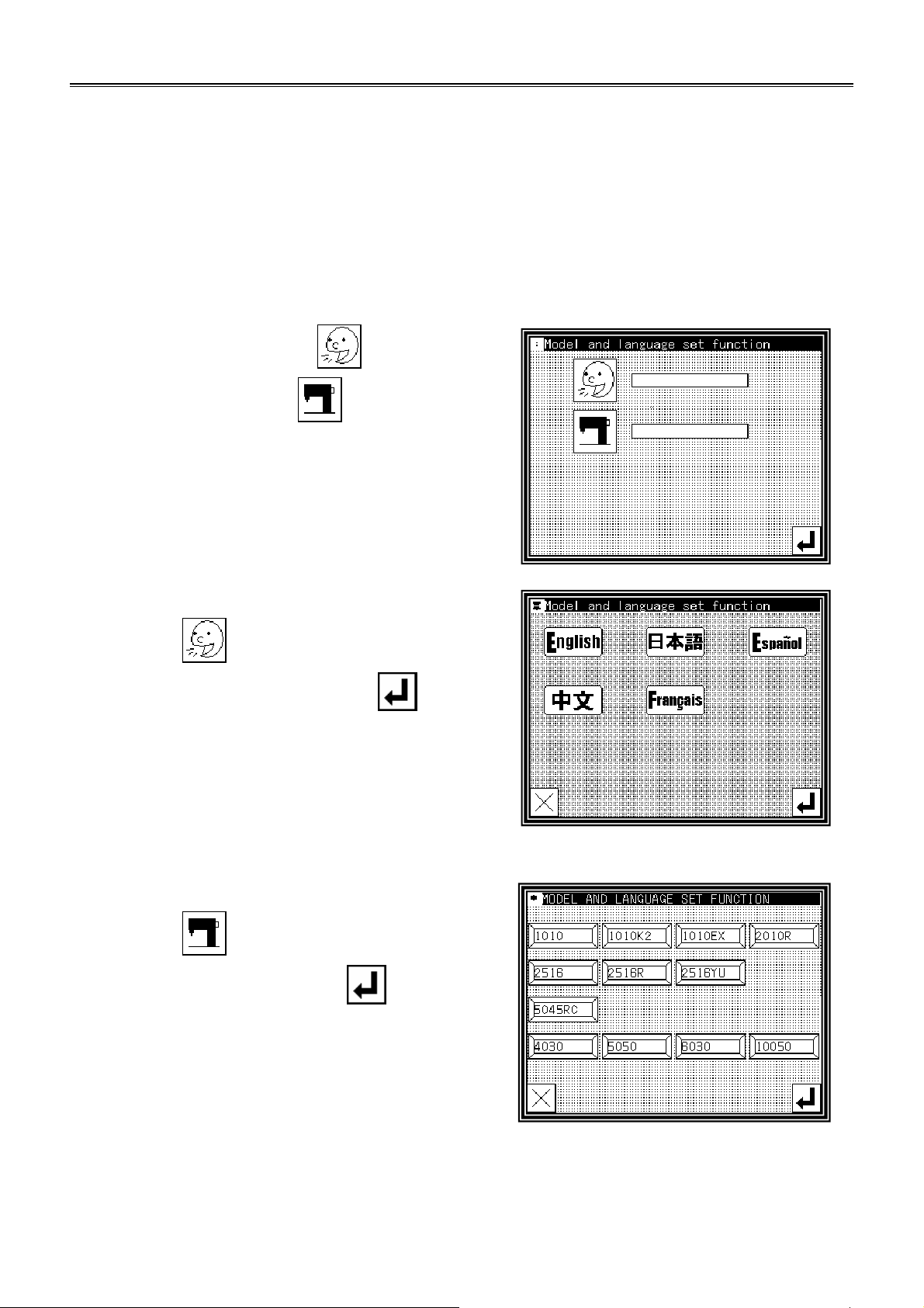
(1)When the power supply is turned on first time, [Model/Language setting] screen is displayed.
►For language setting, press .
►For model setting, press
.
(2)Language setting
►press .
►Choose Language button, then press .
(3)Model setting
►press .
►Choose Model button, then press .
[6] - 1
Page 14
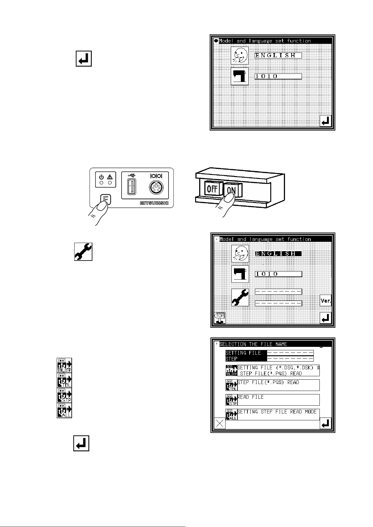
(4) Model / Language setting screen is displayed again.
► Press .
(5) Please turn the power off according to the display
of the message.
(6) Setting table / Step file setting (
► While holding down the [F] key on the front panel of the control box, turn the machine power ON. (Keep pushing [F]
key until red LED on the front panel is turned on.)
If setting is not necessary, goto (9).
+
)
(7)Setting table / Step file setting
►Press .
(8)
Setting table / Step file setting mode
►Choose one of following buttons.
Reads Setting table and Step file
Reads Setting table only
Reads Step file only
Reads System file ,Setting table and Step file
►Connect USB memory
to the connector on the front panel of the control box, then,
press
.
, which above data is contained,
[*1]
[6] - 2
Page 15
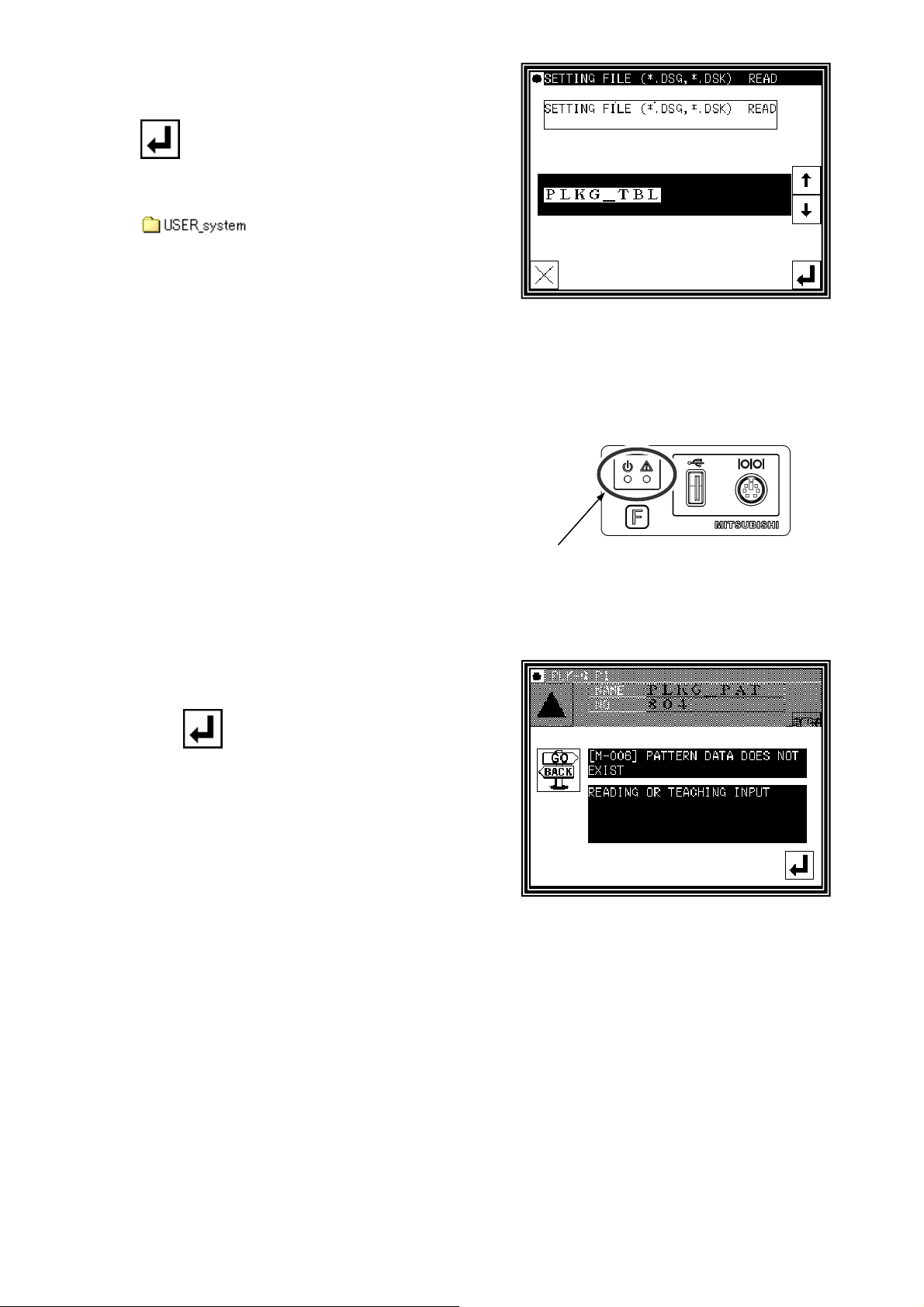
►After file name selection screen is displayed, choose target
filename by using up and down arrow button, then press
.
[*1] Setting table and Step file must be saved in the
[
] folder in the USB memory.
(9)Re-turning on the power supply
► Please turn the power off according to the display of the message.
► After check the LED lamp on the front panel of the control box
Is completely off, turn the power on.
Check the LED lamp is OFF
(10)Initial condition
► At initial condition, the message like a right picture is
displayed.
Press
or read sewing pattern data. ( Refer to technical manual
[ Operation panel ].)
to switch to the Standard screen, then create
[6] - 3
Page 16
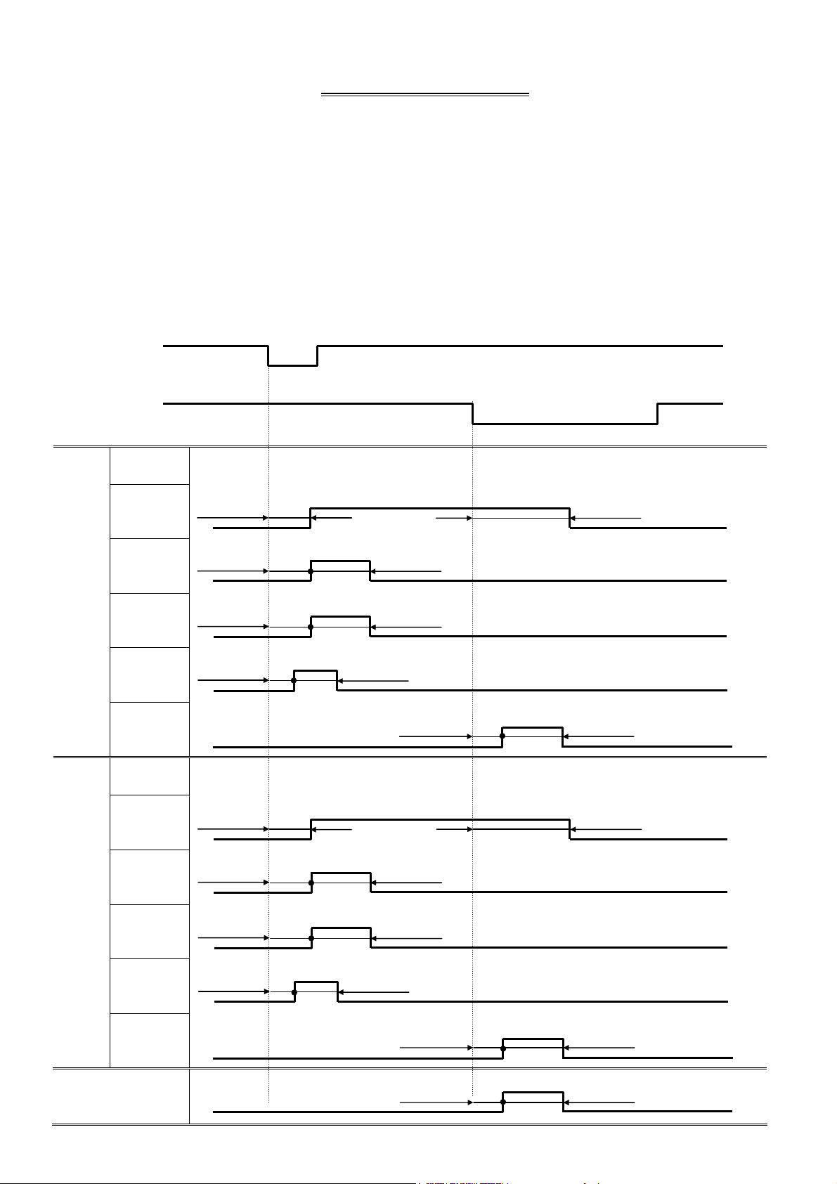
[7] Timing chart
1.Thread trimming timing chart
·Timing for thread trimming output [T] :
Program mode [Thread trimming/release timing] -- [LTM] T1~T5
Program mode [Thread trimming/release timing] -- [TRS] msec / deg
Program mode [Thread trimming/release timing] -- [TRE] msec / deg
·Timing for thread release output [L] :
Program mode [Thread trimming/release timing] -- [LLM] L1~L5
Program mode [Thread trimming/release timing] -- [LRS] msec / deg
Program mode [Thread trimming/release timing] -- [LRE] msec / deg
·Timing for wiper output [W] :
Program mode [Wiper] -- [W1] msec
Program mode [Wiper] -- [W2] msec
Needle down
position DN
Needle up
position UP
LTM
setting
ON
ON
Thread trimming output [T]
Thread release output [L]
T1
T2
T3
T4
T5
LLM
setting
L1
L2
TRS(deg) TRE(ms)
ON
TRS(deg) TRE(deg)
ON
TRS(deg) TRE(ms)
ON
TRS(ms) TRE(ms)
ON
TRS(ms) TRE(ms)
ON
LRS(deg) LRE(ms)
ON
LRS(deg) LRE(deg)
ON
Wiper [W]
L3
L4
L5
LRS(deg) LRE(ms)
ON
LRS(ms) LRE(ms)
ON
LRS(ms) LRE(ms)
ON
W1(ms) W2(ms)
ON
[7] - 1
Page 17

2.Timing chart for [Clamp of output ON/OFF delay setting]
Clamp input 1~8
IF1~IF8
ON ON
1A~8A 1B~8B
Clamp output 1~8
OF1~OF8
ON
3.Timing chart for [Priority of clamp]
Clamp input 1
IF1
ON
Clamp input 2
IF2
Clamp input 3
IF3
Clamp input 4
IF4
[WHY]=[OFF]
Clamp output 1
OF1
Clamp output 2
OF2
Clamp output 3
OF3
Clamp output 4
OF4
[WHY]=[ON]
Clamp output 1
OF1
ON
ON
ON
ON
ON
ON
ON
ON
ON
Clamp output 2
OF2
Clamp output 3
OF3
Clamp output 4
OF4
ON
ON
ON
Note: [WHY]=[ON]
* The clamp input signal [IF2],[IF3],[IF4] is invalidated when clamp output 1 is not ON.
* The clamp input signal [IF2] is validated when clamp output 1 is ON.
* The clamp input signal [IF3] is validated when clamp output 2 is ON.
* The clamp input signal [IF4] is validated when clamp output 3 is ON.
[7] - 2
Page 18

4.Timing chart for
[Clamp link setting (CF)]=ON, [Valid Number of clamp setting (FN)]=4
Clamp input 1
IF1
Clamp output 1
OF1
ON
1A
ON
ON
1B
Clamp output 2
OF2
Clamp output 3
OF3
Clamp output 4
OF4
Note: Halt switch is validated.
2A
ON
3A
ON
4A
ON
4B
5.Timing chart for
[Selection of pneumatic pressure two-step (AF2)]=ON
Can not use other function in “Work holder” mode.
ON
Pneumatic pressure
two-step clamp
input signal A2F
Start
input signal SRT
ON ON ON ON ON
ON ON
2B
3B
Pneumatic pressure
two-step clamp
low pressure output AFL
Pneumatic pressure
two-step clamp
high pressure output AFH
Pneumatic pressure
two-step clamp
eject pressure output AFE
Movement of
sewing machine
ON ON ON
ON ON ON
ON
ON
1T
ON
[7] - 3
Page 19

6.The divisions of clamp setting [OFB]=2
Setting of [FN],[CF],[F4BN],[F4SN] is invalidated when above setting.
[WHY]=OF,[OFB]=2,[CF1]=ON,[CF2]=OF,[F21N]=4,[F22N]=3
When not using the clamp step input.
Clamp input 1
IF1
ON
ON
Clamp input 2
IF2
Clamp input 3
IF3
Clamp input 4
IF4
Clamp input 5
IF5
Clamp input 6
IF6
Clamp input 7
IF7
Clamp input 8
IF8
Start input signal
SRT
The divisions of clamp 1,
[F21N]=4
Clamp output 1
OF1
Clamp output 2
OF2
1A
ON
2A
ON
ON
ON
ON
ON
ON
ON
ON
2B
2A
ON
Clamp output 3
OF3
Clamp output 4
The divisions of clamp 2,
[F22N]=3
OF4
Clamp output 5
OF5
Clamp output 6
OF6
Clamp output 7
OF7
Clamp output 8
OF8
Movement of
sewing machine
3A
ON
4A
ON
5A
ON
6A
ON
7A
4B
ON
Note 1.When the setting ([CF1]=ON), clamp input 1 is link input.
2.When the setting ([CF2]=ON), clamp input 5 is link input.
3B
3A
ON
4A
ON
ON
[7] - 4
Page 20

7.The divisions of clamp setting [OFB]=2(When using the clamp step input.)
Setting of [FN],[CF],[F4BN],[F4SN] is invalidated when above setting.
[WHY]=OF,[OFB]=2,[CF1]=ON,[CF2]=OF,[F21N]=4,[F22N]=4
When using the clamp step input.
The clamp step
(forward direction)
division 1 FP1
The clamp step
(backward direction)
division 1 FM1
The clamp step
(forward direction)
division 2 FP2
The clamp step
(backward direction)
division 2 FM2
Start input signal
SRT
ON
ON ON
ON
ON
ON
ON
ON ON ON ON
ON
ON
The divisions of clamp 1,
[F21N]=4
Clamp output 1
OF1
Clamp output 2
OF2
Clamp output 3
OF3
Clamp output 4
The divisions of clamp 2,
[F22N]=4
OF4
Clamp output 5
OF5
Clamp output 6
OF6
Clamp output 7
OF7
Clamp output 8
OF8
Movement of
sewing machine
1A
ON
2A
ON
3A
ON
3A
3B
ON
4A
ON
5A
ON
6A
ON
7A
ON
8A
ON
8B
8A
ON
ON
[7] - 5
Page 21

8.The divisions of clamp setting [OFB]=4
Setting of [FN],[CF],[F21N],[F22N],[CF1],[CF2] is invalidated when above setting.
Clamp(O1,O2),(O3,O4),(O5,O6),(O7,O8) is link movement when above setting.
Only in this case, the block division operation is possible by the setting of [F4BN].
[WHY]=OF,[OFB]=4,[F4BN]=4
When not using the clamp step input.
Clamp input 1
IF1
ON
ON
ON
Clamp input 2
Clamp input 3
Clamp input 4
Clamp input 5
Clamp input 6
Clamp input 7
Clamp input 8
Start input signal
Clamp output 1
1
2
Clamp output 2
IF2
IF3
IF4
IF5
IF6
IF7
IF8
SRT
OF1
OF2
1A
ON
2A
ON
ON
2B
ON
ON
ON
ON
ON
1A
1B
2A
ON
2B
ON
2A
ON
Clamp output 3
2
2
OF3
Clamp output 4
OF4
Clamp output 5
3
2
OF5
Clamp output 6
OF6
Clamp output 7
4
2
OF7
Clamp output 8
OF8
←Block number of clamp
←Number of clamps
Movement of
sewing machine
3A
ON
4A
ON
5A
ON
6A
ON
7A
ON
8A
ON
ON
[7] - 6
Page 22

9.The divisions of clamp setting [OFB]=4
Setting of [FN],[CF],[F21N],[F22N],[CF1],[CF2] is invalidated when above setting.
Clamp(O1,O2),(O3,O4),(O5,O6),(O7,O8) is link movement when above setting.
Only in this case, the block division operation is possible by the setting of [F4BN], and block
step operation is possibleby the setting of [F4SN].
[WHY]=OF,[OFB]=4,[F4BN]=4,[F4SN]=4
When not using the clamp step input.
The clamp step
(forward direction)
general input signal SFP
The clamp step
(backward direction)
general input signal SFM
Start input signal
SRT
Clamp output 1
1
2
OF1
Clamp output 2
OF2
Clamp output 3
2
2
OF3
Clamp output 4
OF4
Clamp output 5
3
2
OF5
Clamp output 6
OF6
ON
1A
ON
ON ON ON ON
ON
ON
1A
1B
2A
ON
2B
ON
2A
ON
3A
ON
4A
ON
5A
ON
6A
ON
4
2
←Block number of clamp
←Number of clamps
Clamp output 7
OF7
Clamp output 8
OF8
Movement of
sewing machine
7A
ON
8A
ON
ON
[7] - 7
Page 23

[8] Customized input/output
p
1.Customized input/output configuration diagram
[8] - 1
(Refer to page[8]-3) (Refer to page[8]-2) (Refer to page[8]-2) (Refer to page[8]-3)
A B C D E
(Input port)
·Terminal block
·Connector
Input
control
section
Alternate
Input reversal
Physical
input
I1
I2
I3
I4
I5
:
:
:
Virtual
input
S1
F
Two stage
clamp input
Sewing machine
operation prohibit
Home position
return prohibit
Virtual input 0
Virtual input 1
:
:
:
:
Virtual
out
ut
T
L
W
OF1
PF
Two stage
clamp output
Sewing machine control
Virtual output 0
Virtual output 1
:
:
:
:
Physical
output
O1
O2
O3
O4
O5
:
:
:
Output
control
section
Alternate
output reversal
(Output port)
·Terminal block
·Connector
chopping
ON/OFF delay
WL
[13]-1
Page 24

2.Outline of customized input/output mode
p
(A to E below correspond to A to E on the previous page.)
(1)Customizing the input signal
A.The ON/OFF signal input from the input port passes through the input control section (no operation,
alternate operation, signal reversal), and is then stored in the physical input area corresponding to the
input port.
B.
Each signal stored in the physical input area is connected to a desired position in the sewing machine
control virtual input port.
(Refer to page[8]-3)
(Refer to page[8]-2)
C.The sewing machine carries out control based on the function assigned to the virtual input area.
(2)Customizing the output signal
D.As opposed to the customized input, the virtual output area port, assigned a specific meaning, can be
connected and set to a desired position in the physical output area port.
E.
The signal for each port in the physical output area passes through the output control section
(no operation, delay circuit, alternate, etc.), and is then output to the output port.
3.Customizing the virtual input/output
Input control
section
Alternate
Input reversal
Physical
input
I1
I2
I3
I4
Customized
input
Virtual
input
SRT
F
Virtual
out
ut
T
L
FU
Sewing machine control
Customized
output
(Refer to page[8]-2)
(Refer to page[8]-3)
Output control
Physical
output
O1
O2
O3
O4
section
Alternate
ON/OFF delay
output reversal
chopping
Selection and connection of physical input/output port and virtual input/output port
For example, to connect the physical input port [I1] and virtual input port [SRT] (start) and to connect the
physical output port [O1] and virtual output port [T] as shown in the diagram, set as follows.
1. Using customized input, select the [I1] input functions, and set SRT.
2. Using customized output, select the [O1] input functions, and set SRT.
With the above settings, [I1] and [SRT], and [O1] and [T] will be connected.
One port from the virtual input ports can be selected for the [I*] port by changing the setting.
One port from the virtual output ports can be selected for the [O*] port by changing the setting.
[8] - 2
Page 25

4.Block diagram (input control section)
Standard Physical input
A
OF
ON
B
Logic changeover Operation changeover
Alternate
NO
AL
C
5.Explanation of operations (input control section)
The input signal passes through the A point, B point and C point of the input port, and finally is connected
to the physical input
A point
B point (1) When the logic setting is set to "normal"(OF), the operation will be the same as the input
Inputs the signal to the input port from an external source.
signal A point.
(2) When the logic setting is set to "reverse"(ON), the operation will be the reverse of the input
signal A point.
C point (1) When the operation selection is set to "normal"(NO), the operation will be the same as the
input signal B point.
(2) When the operation selection is set to "alternate"(AL), the signal will turn ON at the first rising
edge, turn OFF at the second rising edge, and will turn ON at the third rising edge. The signal
waveform will repeatedly turn ON and OFF at the input rising edge.
The C point signal input and controlled in the above manner is input into the physical input port.
Logic
changeove
Logic operation
selection when
logic changeover is
set to "normal"
Logic operation
selection when logic
changeover is set to
"reverse"
Input port A
“Normal” B
"Reverse" B
“Normal” C
"Alternate" C
“Normal” C
"Alternate" C
[8] - 3
Page 26

6.Block diagram (output control section)
y
Physical output
O1
O2
O3
Alternate
OFF delay
NO
D
Setting time
Chopping
Full wave time
Setting value x 100μs
OFF delay
OF
ON
Operation
selection
Full wave time
NO
AL
Dut
A
100% ON
66% ON(8ms ON/4ms OFF)
66% ON(4ms ON/2ms OFF)
50% ON(4ms ON/4ms OFF)
50% ON(2ms ON/2ms OFF)
33% ON(2ms ON/4ms OFF)
17% ON(2ms ON/10ms OFF)
8% ON(2ms ON/22ms OFF)
Manual setting
C
ON delay
OF
ON
ON delay
7.Explanation of operation (output control section)
The operation of the signal output from the physical output is selected and then the signal is connected to
the output port F point.
A point
Logic operation selection
(1)
When "normal"(NO) is selected, the input waveform is connected.
(2)
When "alternate"(AL) is selected, the signal will alternately turn ON and OFF, turning ON at the
first rising edge and OFF at the next rising edge.
Input signal O1
“Normal” A
“Alternate” A
Setting time
E
Logic
changeover
OF
ON
Output port
B
D
[8] - 4
Page 27

B point ON
delay setting
(1)
When "invalid" is selected, the same signal as the A point will be output to the B point.
(2)
When "valid" is selected, the waveform will rise after the {set value x 100μs} time (*1) set with the
A point input waveform. (ON delay)
Input signal A
“Invalid” B
“Valid” B
C point OFF delay setting
(1)
When "invalid" is selected, the same signal as the B point will be output to the C point.
(2)
When "valid" is selected, the ON time will be delayed by the {set value x 100μs} time (*2) set with
the B point input waveform.
Input signal B
“Invalid” C
“Valid” C
D point Logic setting
(1)
When "normal" is selected, the C point signal will be output to the D point without any changes.
(2)
When "reverse" is selected, D point signal will be reversing signal of the C point signal.
Input signal C
Normal D
“Reverse” D
E point Chopping setting
(1) When [100%ON] is set, there is no change, and input signal of D point is output to E point.
(2) When other than [100%ON] is set, outpu of E point is on while {setting time x 100 us}. Afterwards the
output becomes square wave accordning to duty ratio setting.
Input signal D
“
100%ON” E
“
Other than 100%ON” E
Full wave time
*1 Delay time to ON
Duty
100% ON
66% ON(8ms ON/4ms OFF)
66% ON(4ms ON/2ms OFF)
50% ON(4ms ON/4ms OFF)
50% ON(2ms ON/2ms OFF)
33% ON(2ms ON/4ms OFF)
17% ON(2ms ON/10ms OFF)
8% ON(2ms ON/22ms OFF)
Manual setting
*2 Delay time to OFF
[8] - 5
Page 28

[9] Input/Output signal
1.Input signal setting table
Code Function Specifications
FSP
FSM
FP1
FM1
FP2
FM2
IFR
A2F Pneumatic two-step clamp
IF1~IF8 Clamp input signal 1 ~ 8 When IF1 input is on, OF1 output is turned on.
F1C~F8C Clamp output prohibition signal
OFC
WC
TC
S6
HPC
TH2
THS
ARS
IO0~IOF
NO
SRT
HP
PF
JGP
JGM
STP
Clamp all step ON signal Whenever FSP input is on, clamp output [1],[2],[3],[4],[5],[6],[7],[8] turned on
Clamp all step OFF signal Whenever FSM input is on, clamp output [8],[7],[6],[5],[4],[3],[2],[1] turned off
Clamp division1 step ON
signal
Clamp division1 step OFF
signal
Clamp division2 step ON
signal
Clamp division2 step OFF
signal
All clamp output clear signal If IFR signal is on, all clamp outputs are turned off.
switch input signal
1 ~ 8
All clamp output cancel signal When OFC input is on, OF1 to OF8 outputs are prohibited.
Wiper output cancel signal When WC input is on, W output is prohibited.
Trimmer output cancel signal When TC input is on, Thread trimmer sequence output T, L and W is
Thread trimming protection
signal
Home positioning prohibition
signal
Upper thread sensor 2 input
signal
Upper thread sensor input
signal
Less pressure detection signal When ARS input is on, all operation is interrupted, and error [E-025] is
General purpose input 0 ~ F When IO0 input is on, OT0 output is turned on at the same time.
No operation signal Anything does not operate, if NO input is turned on.
Start signal When SRT input is on, sewing operation is started. However, when clamp
Home position returning signal When HP input is on, home position returning operation is executed.
Presser foot signal When PF input is on, The presser foot will return to home position.
JOG plus signal When JGP input is on, XY table is moved in positive direction according to
JOG minus signal When JGP input is on, XY table is moved in negative direction according to
Halt signal When STP input is on, machine is stopped.
one by one. However, when [ Program mode > Clamp output > number of
effective clamp (FN) ] is set to 1, FSP input is ineffective.
one by one. However, when [ Program mode > Clamp output > number of
effective clamp (FN) ] is set to 1, FSM input is ineffective.
Whenever FP1 input is on, clamp output [1],[2],[3],[4] turned on one by one.
Whenever FM1 input is on, clamp output [4],[3],[2],[1] turned off one by one.
However [ Program mode> clamp output block division number setting (OFB)]
is set to no or set to 4, or [ number of valid clamp setting (F21N)] is set to 1,
FM1 input is ineffective.
Whenever FP2 input is on, clamp output [5],[6],[7],[8] turned on one by one.
Whenever FM2 input is on, clamp output [8],[7],[6],[5] turned off one by one.
However [ Program mode> clamp output block division number setting (OFB)]
is set to no or set to 4, or [ number of valid clamp setting (F22N)] is set to 1,
FM2 input is ineffective.
Whenever A2F input is on, following operation (1), (2), (3) is repeated.
This signal is effective when [Program mode > Setting for Pneumatic two-step
clamp(AF2)] is on.
(1)When A2F input is on first time, AFL output is turned on.
(2)When A2F input is on second time, AFH output is turned on.
(3) When A2F input is on third time, AFE output is turned on.
When IF1 input is on again, OF1 output is turned off.
(same from IF2 toIF8)
When F1C input is on, OF1 output is prohibited.
(same from F2C to F8C)
prohibited.
When S6 input is on while machine is driving, the machine is stopped and
when S6 input is off, the machine start driving again.
When S6 input is on while thread trimming operation, machine is stopped
after trimming.
When HPC is ON, home returning operation by the home positioning key or
HP signal is prohibited.
When setting of [ Program mode > Needle thread breaking sensor 2
ON/OFF ] is on, the signal can be used for thread breakage detection input
(channel 2).
When setting of [ Program mode > Needle thread breaking sensor ON/OFF ]
is on, the signal can be used for thread breakage detection input.
displayed. (Returns by power supply re-turning on)
(same from IO1 to IOF)
output is turned off, this signal is invalid.
However, please note there is a timing that becomes invalid, for example
while machine is running.
When PF input is on again, presser foot goes to down position.
the pattern.
the pattern.
[9] - 1
Page 29

< sequel to INPUT SIGNAL >
Code Function Specifications
BC
CCL
SRC
CCU
CCD
UAD
UDC
DAD
DDC
KNK
RNK
WNK
INK
MNK
CNK
PNK
NNK
FNK
SNK
P01
P02
P04
P08
P16
P32
IFA
HES
I_9
I_A
Fixed angel (rotation/reverse
rotation) signal
Counter clear signal When CCL input is on, UP/DOWN counter is cleared.
Start cancel signal When SRC input is on, sewing operation with Stringhalt is prohibited.
Up counter clear signal When CCU input is on, UP counter is cleared.
Down counter clear signal When CCD input is on, DOWN counter is cleared.
Up counter addition signal When UAD input is on, 1 is added to UP counter
Up counter subtraction signal When UDC input is on, 1 is subtracted from UP counter
Down counter addition signal When DAD input is on, 1 is added to DOWN counter
Down counter subtraction
signal
Signal that invalidates MENU
key
Signal that invalidates “pattern
read” key
Signal that invalidates “pattern
write” key
Signal that invalidates
“teaching input” key
Signal that invalidates
“teaching modification” key
Signal that invalidates
“teaching conversion” key
Signal that invalidates
“program mode” key
Signal that invalidates “IN/OUT
setting” key
Signal that invalidates “function
mode” key
Signal that invalidates “speed”
key
Pattern number switch signal
+1
Pattern number switch signal
+2
Pattern number switch signal
+4
Pattern number switch signal
+8
Pattern number switch signal
+16
Pattern number switch signal
+32
DO NOT USE
Machine head tilting detection
signal
DO NOT USE
DO NOT USE
To confirm the needle thrust position, the needle is stopped just before the
sewing material. Whenever BC input is ON, operation of [rotation] → [reverse
rotation] → [rotation] is repeated. When the start switch is on afterwards,
following sewing operation is started. However, if the following data is non
stitch feed, the message [M-020] is appeared, in this case please move the
needle to up position and re-turning on the start switch. Setting value of fixed
angle can be set in the [ Function mode > Needle down angle setting].
When DDC input is on, 1 is subtracted from DOWN counter
When KNK is on, “MENU” key becomes invalid.
When RNK is on, “pattern read” key becomes invalid.
When WNK is on, “pattern write” key becomes invalid.
When INK is on, “teaching input” key becomes invalid.
When MNK is on, “teaching modification” key becomes invalid.
When CNK is on, “teaching conversion” key becomes invalid.
When PNK is on, “program mode” key becomes invalid.
When NNK is on, “IN/OUT setting” key becomes invalid.
When FNK is on, “function mode” key becomes invalid.
When SNK is on, “speed” key becomes invalid.
When P01 is on, pattern data number is switch to 801 (800+1).
When P02 is on, pattern data number is switch to 802 (800+2).
When P04 is on, pattern data number is switch to 804 (800+4).
When P08 is on, pattern data number is switch to 808 (800+8).
When P16 is on, pattern data number is switch to 816 (800+16).
When P32 is on, pattern data number is switch to 832 (800+32).
< When you want to change to other patterned numbers >
ex.1) pattern number to 803
turns on P01 input and P02 input
P01 (+1) + P02 (+2) + 800 = 803
ex.1) pattern number to 811
turns on P01, P02 and P08 input
*Pattern number can be changed within the range from 800 to 863.
*P01,P02,P04,P08,P16,P32 is effective when [Pattern select function by
external signal(APC)] has been set to ON.
When HES input is on, message [M-038] is displayed.
P01 (+1) + P02 (+2) + P08 (+8) + 800 = 811
[9] - 2
Page 30

< sequel to INPUT SIGNAL >
Code Function Specifications
SP0~SP9
SPU
SPD
CK1
CK2
Speed dial signal Speed dial value is switched to 0~9.
Speed up signal Speed dial value is increased +1.
Speed down signal Speed dial value is decreased -1.
Cassette jig sensor 1 signal
Cassette jig sensor 2 signal
When CK1 and CK2 inputs is on, OF1 output turn on.
*CK1 and CK2 is effective when [Cassette jig function ON/OFF(CHK)] and
[Cassette jig sensor ON/OFF(CSN)] has been sets to ON.
[9] - 3
Page 31

2.Output signal setting table
Code Function Specifications
OT0~OTF General purpose output 0 ~ F
FN1~FNH Function code output 1 ~ H
OF1~OF8 Clamp output 1 ~ 8 When IF1 is on, OF1 output is reversed (same OF2 to OF8 )
NO
PF
AFL
AFH
AFE
DHP
D2H
RED
DSW
SP
TSE
END
DCS
DST
HPO
ERR
CUE
CDE
DTS
--1
DRT
DN
CB
UP
PWR
PUS
MSG
OP1 Option output 1 General purpose output signal 1
OP2 Option output 2 General purpose output signal 2
SSW
MOV
[NO]output Nothing is done
Trimmer output Trimming operation is done
T
Thread tension release output Thread tension release operation is done
L
Wiper output Wiper operation is done
W
Presser foot output Presser foot operation is done
Pneumatic two-step switch
clamp low pressure output
Pneumatic two-step switch
clamp high pressure output
Pneumatic two-step switch
clamp excess pressure release
output
Home position output When XY table is sopped on the home position, DHP output is turned on.
Second home position output When XY table is sopped on the second home position, DHP output is turned
Preparation ready output When the machine is ready state (when clamp output is on), RED output is
Sewing in progress output When the machine is sewing, DSW output is turned on. When machine is
Sewing machine rotation start
output
Trimming start output When trimming sequence (down position) is started, TSE output is turned on.
Sewing completion output When a sewing pattern operation is finished, END output is turned on.
Halt code output When the halt code data (USTP, DSTP) is read while sewing, DCS output is
Halt in progress output When the machine is on halt state, DST output is turned on. When the
Home returning in progress
output
Error output When the error or message is displayed on the operation panel, ERR output
Count up completion output When the current value of up counter is reached at counter set value, CUE
Countdown completion output When the current value of down counter is reached at 0, CDE output signal is
Halt in progress output after
upper thread sensor detection
DO NOT USE
Sewing machine rotation in
progress output
Down position output When the needle is down position, DN output is turned on.
Buzzer output While the buzzer in the operation panel is on, CB output is turned on.
Up position output When the needle is up position, UP output is turned on.
Power on output While power supply is on, PWR output signal is turned on.
Presser hoot home position
output
Message display output When the message is displayed on the operation panel, ERR output is turned
Halt signal being on output
Sending table's moving output
signal
When IO0 is on, OT0 output at the same time (same from OT1 to OTF )
When FUN1 code is read while sewing operation, FN1 output is reversed.
(same from FN2 to FNH)
When A2F input is on first time, AFL output is turned on.
Setting is effective when [ Program mode > Clamp > Pneumatic two-step
switch clamp ON/OFF (AF2)] is on.
When A2F input is on second time, AFH output is turned on.
Setting is effective when [ Program mode > Clamp > Pneumatic two-step
switch clamp ON/OFF (AF2)] is on.
When A2F input is on third time, AFE output is turned on.
Setting is effective when [ Program mode > Clamp > Pneumatic two-step
switch clamp ON/OFF (AF2)] is on.
on.
turned on. When machine is start sewing, RED is turned off.
stopping on the home position, DSW output is turned off.
After non stitch feed, when the sewing machine start to rotate, SP output is
turned on. When home positioning is executed, SP output is turned off.
When trimming sequence is finished (when all the outputs of T, L and W are
turned off), TSE output is turned off.
When the next sewing is started, END output is turned off.
turned on. When the machine restarts DCS output is turned off.
machine restarts DST output is turned off. However, it is not output while
stopping by the USTP code or the DSTP code.
While the operation of home returning by the home positioning key or HP
signal, HPO output is turned on.
is turned on.
output signal is turned on. When the current value is cleared, CUE output is
turned off.
turned on. When the current value is initialized, CDE output is turned off.
When the machine is on halt state with thread breakage, DTS output is
turned on. When the machine restarts, DTS output is turned off.
While the machine is rotating, DRT output is turned on.
(includes rotation in winding mode)
(including count up/countdown message display)
While presser foot is on the home position, PUS output is turned on.
on.
SSW is turned on during power supply is on. However, input signal STP turns
on SSW is turned on with blinking.
Turn on during XY table is moving. (It does not turn on when automatic
sewing operation)
[9] - 4
Page 32

[10] What happened? Could it be an error?
When an error occurs, the error code and corresponding message appear on the operation panel. Take
a corrective action in accordance with the message. This section describes the errors and others that do
not appear on the operation panel.
[Case1]
Nothing appears on the operation panel when you turn the power switch ON.
(Both the front panel green (power) and red (warning) LEDs are off.)
[Checking Items and Corrective Actions]
Is the power switch definitely turned ON?
▪Check the power supply connection and turn ON the power switch again.
Is the power supply connector fully connected?
▪Check the power supply connector connection, contact state and others,
and then turn ON the power switch again.
Refer to “(12) Unit Wiring Diagram.”
Is there a blown fuse in the control box?
▪Replace the blown fuse with a fuse of identical capacity.
Refer to page. [2]-2
Is a harness inside the control box disconnected?
▪Check the connections of the harnesses inside the control box, and turn
ON the power switch again.
Refer to “(15) Wiring Diagram Inside Control Box”
[10] - 1
Page 33

[Case2]
Nothing appears on the operation panel when you turn the power switch
ON. (The front panel red (warning) LED is on or flickering.)
Pattern1 Blink once
Red (warning) LED flickering pattern
☼ - - - ☼ - - - ☼ - - - ☼ - - - ☼ - - -
Pattern2 Blink twice
Pattern3 Blink 3 times
Pattern4 Blink 4 times
☼ - ☼ - - - ☼ - ☼ - - - ☼ - ☼ - - -
☼ - ☼ - ☼ - - - ☼ - ☼ - ☼ - - -
☼ - ☼ - ☼ - ☼ - - - ☼ - ☼ - ☼ - ☼ - - -
☼ : ON - : OFF
[Checking Items and Corrective Actions]
Is the front panel red (warning) LED on?
▪A system error occurred. Reinstall the system.
Refer to “[Action Method 1] Reinstalling the System” later in this section.
▪If you take a corrective action but no improvement is made, consult with
your local representative.
Is the front panel red (warning) LED showing flickering pattern 1?
(Refer to the above table.)
▪A communication error occurred. Please turn on the power again after
check connection of the operation panel cable.
▪If you take a corrective action but no improvement is made, consult with
your local representative.
Is the front panel red (warning) LED showing flickering pattern 2?
(Refer to the above table.)
Open the control panel lid. Is fuse 2.5A on the PLK-G3-CPU board blown?
▪Replace the blown fuse with a fuse of identical capacity.
Refer to page. [2]-2
Is the front panel red (warning) LED showing flickering pattern 3?
(Refer to the above table.)
▪The backlight of the operation panel may be burnt out. Consult with your
local representative.
Is the front panel red (warning) LED showing flickering pattern 4?
(Refer to the above table.)
▪There is a problem in the control box. Consult with your local
representative.
[10] - 2
Page 34

[Case3]
Though you turn the power switch ON and a screen appears on the
operation panel, the screen display is incorrect.
[Checking Items and Corrective Actions]
Is the problem solved when you switch the screen or turn the power switch OFF and
then ON again?
▪Reinstall the system.
Refer to “[Action Method 1] Reinstalling the System” later in this section.
[Case4]
I press the foot pedal, but the machine does not run.
The message “MACHINE HEAD TILT WAS DETECTED” appears.
[Checking Items and Corrective Actions]
Is the machine tilted?
▪Return the machine back to its proper state and try again.
▪Check if the tilting sensor switch is damaged or disconnected.
Is the signal HES among the input signals changed?
▪Check input customization.
[Case5]
No screen appears on the operation panel when you turn the power switch
ON. (The front panel red (warning) LED is off.)
[Checking Items and Corrective Actions]
The operation panel may be defective.
▪Consult with with your local representative.
[10] - 3
Page 35

[Action Method 1] Reinstalling the System
The sewing machine is normally shipped with the system installed. However, if a reinstallation is
required for some reasons and others, reinstall the system using a USB memory, and follow the
method below.
(1)Save the system data in a USB memory.
(Refer to page[10]-8 [System data save to USB memory])
►Copy the [
memory.
(2)Turn the machine power OFF and insert the USB memory.
folder where the installed system datas are included, into the root directory of USB
]
System
data
(3)While holding down the [F] key on the front panel of the control box, turn the machine power ON.
(Keep pushing [F] key until red LED on the front panel is turned on.)
(4)Installation is started. Please wait for a while.
+
[10] - 4
Page 36

(5) After installation complete, [Machine
type/Language setting] screen on the
operationpanel is appeared.
(6)Pull out USBmemory.
(7)Language setting
►press .
►Choose Language button, then press .
(8)Model setting
►press .
►Choose Model button, then press .
[10] - 5
Page 37

(9)Setting table / Step file setting
►For Setting table/ step file setting, press .
If setting is not necessary, goto (10).
►Choose one of following buttons.
Reads Setting table and Step file
Reads Setting table only
Reads Step file only
Reads System file ,Setting table and Step file
►Connect USB memory
to the connector on the front panel of the control box, then,
press
►After file name selection screen is displayed, choose target
filename by using up and down arrow button,
then press
.
. Goto (12)
, which above data is contained,
[*1]
[*1] Setting table and Step file must be saved in the
[
] folder in the USB memory.
(10) Model / Language setting screen is displayed again.
► press .
[10] - 6
Page 38

(11)Initialize of set value
►To initialize set value, press .
Setting will be returned to the factory setting)
(
To exit without setting, press
.
(12)Re-turning on the power supply
►Turn the power off.
► After check the LED lamp on the front panel of the control box
Is completely off, turn the power on.
►Reinstallation is complete.
Check the LED lamp is OFF
[10] - 7
Page 39

[System data save to USB memory (using copy tool)]
[Outline] Coping system data of the CD-ROM to the USB memory by using copy tool.
[Note] If
(1) Inset the PLK-G Document CD-ROM to your PC.
Insert USB memory to the USB connector on your PC.
Check the CD-ROM drive and USB memory drive.
(ex. CD-ROM drive= “D:” , USB memory drive = “E:”)
(2) Open the CD-ROM root directory by using exploler etc.
Double click “PLKG System Setup.exe”
(3) After open the PLKG System Setup window, select CD-ROM drive and USB memory drive
respectively.
“ ”, “ ”is already exist in the USB memory, they are
over-written.
(Please move necessary data to other folder or memory before using copy tool.)
(4) Click the “SystemCopy” button.
Data copy will be executed.
(5) When copying is complete, the message will be appeared, then click OK button.
Press
button to close the window.
(6) The system data copy to USB memory is completed. Please confirm the content of USB
memory. Please use this USB memory for system installation.
[10] - 8
Page 40

[System data save to USB memory (manual operation)]
[Outline] Copy the [ ] folder where the installed system datas are included, into the
root directory of USB memory.
However, before installation to the sewing machine, please
the data
in the following way.
(1) Insert CD-ROM(PLK-G Document CD)to the CD drive of the computer.
Insert the USB memory that system data will be preserved.
(2) [
]folder exists under “System Folder”. Copy the folder onto the root directory of
USB memory.
change the attribute of
(3) Left-click the [
] with the mouse.
(4) Click the [File] – [Properties] on the menu bar.
(5) Click "Reading exclusive use" and then, clear
the check box. (make the check box blank).
Then click OK button.
(6) Choose "The change is applied to this
folder, the subfolder, and the file", and
click OK button.
(7) Attribute change complete. Please use this USB memory for system installation.
[10] - 9
Page 41

This page is blank.
[10] - 10
Page 42

1.3Ø AC200V - 240V 50/60Hz
[11] Several power supply
Red
White
Black
Green
ON
OFF
Push button switch assay
K14M47932202
Red
White
Black
Green
1
2
3
4
5
6
To control box
CONB
60-9090-306-108-002
2.1Ø AC200V - 240V 50/60Hz (Except Europe)
[11] - 1
Blue
Brown
Green/
Yellow
Push button switch assay
K14M47932206
OFF
ON
60-9090-306-108-005
Blue
1
Brown
2
3
4
5
Green/
Yellow
6
To control box
CONB
3.3Ø AC380V - 415V 50/60Hz (Except Europe)
60-9090-306-108-002
Black
Black
Brown
Blue
Green/
Yellow
ON
OFF
Push button switch assay
K14M47932203
Brown
Blue
Green
1
2
3
4
5
6
60-9090-306-208-002
Power unit PLK-B-PUC-B40
3-phase transformer 3Ø 800VA
BKO-E3138H02
F1
1
Brown
2
3
4
5
6
Black
Blue
Ground
5A
Black
Brown
Blue
F2
5A
Green/Yellow
Green/Yellow
U
V
W
u
Black
Red
v
w
Blue
60-9090-304-118-006
Black
1
1
Brown
2
2
Blue
3
3
Green/Yellow
4
Green/
Yellow
4
60-9090-304-218-006
60-9090-304-118-006
60-9090-305-108-005
Black
1
1
2
2
Brown
3
3
Blue
4
4
Green/
5
5
Yellow
Black
1
Blue
2
3
4
5
6
Brown
Green/
Yellow
Green/
Yellow
60-9090-306-108-005
To control box
CONB
Page 43

4.1Ø AC100V - 120V 50/60Hz
r
w
White
Black
Green
OFF
Push button switch assay
K14M47932205
60-9090-306-108-005
ON
White
Black
Green
1
1
2
2
3
3
4
4
5
5
6
6
5.1Ø AC200V - 240V 50/60Hz (Europe)
[11] - 2
Blue
1
Blue
Brown
Green/
Yello
Power code
K14M73981530
60-9090-306-208-005
Brown
Green
Green/
Yellow
1
2
2
3
3
4
4
5
5
6
6
Power unit PLK-B-PUC-A10
60-9090-306-108-005 60-9090-304-108-005
Black
Brown
Green/Yellow
Ground
Noise filter unit PLK-G-NU-SET
Ferrite core
Black
Brown
Blue
Green/Yellow
Green/
Yellow
Ground
Single-phase transformer 1Ø 600VA
BKO-E3140H03
100V
Black
F1
20A
Brown
Green/Yellow
0V
60-9090-304-118-00660-9090-306-108-005
1
1
2
2
3
3
4
4
200V
Black
0V
Red
PLK-B1-FIL P.W.B
60-9090-305-208-005
Black
1
1
Brown
2
2
Blue
3
3
Green/Yellow
4
4
60-9090-304-218-006
60-9090-305-208-005
60-9090-305-108-005
Black
Brown
Blue
Green/
Yellow
Black
1
1
Brown
2
2
3
3
Blue
4
4
Green/
5
5
Yellow
60-9090-305-108-005
Black
1
1
2
2
own
B
3
3
Blue
4
4
Green/
5
5
Yellow
Black
1
Blue
2
3
4
5
6
Brown
Green/
Yellow
Green/
Yellow
60-9090-306-108-005
Black
Brown
Blue
Green/
Yellow
Green/
Yellow
60-9090-306-108-005
To control box
CONB
1
2
3
4
5
6
To control box
CONB
Page 44

[12] Unit wiring diagram
■For connector pin details, refer to “[13] Connectors Layout” and “[14] Pin Number of Connectors.”
[12]-1
Page 45

[12]-2
Page 46

[13] Connectors layout
[Back side of machine head]
[Back side of control box] [front panel of the control box]
[13] - 1
Page 47

[14] Pin number of connectors
1.Back side of
control box/sewing machine
CONA (Operation panel)
Signal Pin No.
RXD-IO 1
RXD-PAL 2
TXD-IO 3
GND 4
+12V 5
TXD-PAL 6
CONB (Power supply)
Signal Pin No.
R 1
S 2
T 3
- 4
E 5
FG 6
CONC (DC power supply for various solenoids
(same for CONN))
Signal Pin No.
+24V 1
GND 2
COND (Main axis servo motor)
Signal Pin No.
W 1
U 2
V 3
FG 4
CONE (Various solenoids (same for CONP))
Signal Pin No.
+12V 1
SCL OUT 2
SDA OUT 3
GND 4
+12V 5
SCL IN
SDA IN 7
GND
X HOME 9
Y HOME 10
Z HOME 11
STP
SCL OFF 13
SCL_TE
SDA_TE 15
CONF (Main axis encoder)
Signal Pin No.
GND 1
UP 2
DN 3
+5V 4
FG 5
EA
ERA 7
EB
ERB 9
- 10
EZ 11
ERZ
EU 13
EV
EW 15
6
8
12
14
6
8
12
14
CONG (XY axis encoder)
Signal Pin No.
GND 1
+5V 2
GND 3
FG 4
ENXAN
ENXBN 6
ENYAN
ENYBN 8
ENXAP 9
ENXBP
ENYAP 11
ENYBP 12
5
7
10
CONH (Foot switch)
Signal Initial setting
+12V +12V 1
I1
I2
VC1
GND GND 5
GND GND 6
I3
GND GND 8
[SRT]
Start input
[IF1]
Work holder output 1
ANI1
Analog input
[IF2]
Work holder output 2
Pin
No.
CONJ (XY axis stepping motor)
Signal Pin No.
XA1 1
XA2 2
XB1 3
YA1 4
FG 5
XB2 6
YA2 7
YB1 8
YB2 9
CONK (PF axis stepping motor)
Signal Pin No.
+24V 1
BR 2
B 3
AR 4
A 5
+24V 6
2
3
4
7
[14] - 1
Page 48

CONL (General purpose iutput)
Signal Initial setting
I8 [NO] No operation 1
GND GND 2
I9 [NO] No operation 3
IA [NO] No operation 4
GND GND 5
IB [NO] No operation 6
IC [NO] No operation 7
GND GND 8
ID [NO] No operation 9
IE [NO] No operation 10
GND GND 11
IF [NO] No operation 12
Pin No.
CONM (General purpose output)
(Output for solenoid valve. The solenoid cannot be drived.)
Signal Initial setting Pin No.
O8 [FN1] Function code 1 1
+24V +24V 2
O9 [FN2] Function code 2 3
OA [NO] No operation 4
+24V +24V 5
OB [[NO] No operation 6
+24V +24V 7
+24V +24V 8
+24V +24V 9
OC [NO] No operation 10
+24V +24V 11
OD [NO] No operation 12
OE [NO] No operation 13
+24V +24V 14
OF [NO] No operation 15
*Refer「3. Ratings value of output」P.[14]-3, for the
ratings of solenoid valve
CONR (USB)
Signal Pin No.
VBUS 1
DM 2
DP 3
GND 4
CONS (RS-232C)
Signal Pin No.
RXD1 1
RXD0 2
TXD1 3
GND 4
+12V 5
TXD0 6
2.PLK-G2-SOL
(1)Input
CON3
Printed
character
GND Ground 1
XH
CON4
Printed
character
YH
CON5
Printed
character
ZH
XHOME
+12V DC12V power supply 3
GND Ground 1
GND Ground 2
YHOME
+12V DC12V power supply 4
GND Ground 1
GND Ground 2
GND Ground 3
ZHOME
+12V DC12V power supply 5
Signal Pin No.
X axis home position
detection
Signal Pin No.
Y axis home position
detection
Signal Pin No.
PF axis home position
detection
2
3
4
[14] - 2
CON6
CON7
CON8
CON9
Printed
character
ES
Printed
character
S6
Printed
character
THS
Printed
character
FSW
Signal Pin No.
I4 [STP] Halt switch 1
GND Ground 2
+12V DC12V power supply 3
O6 [SSW] Halt stop output 4
Signal Pin No.
+12V DC12V power supply 1
I5
GND Ground 3
+12V DC12V power supply 1
I6
GND Ground 3
GND Ground 4
GND Ground 5
+12V DC12V power supply 1
I7 [NO] No operation 2
GND Ground 3
[HES] Mahine tilting
detection input
Signal Pin No.
[THS] Thread
breakage detection
input
Signal Pin No.
2
2
Page 49

(2)Output
CON10
Printed
character
CON11
Printed
character
CON12
Printed
character
CON13
Printed
character
FU
CON14
Printed
character
OP2
CON15
Printed
character
OP1
T
W
L
Signal Pin No.
O1 [T] Trim 1
+24V DC24V power supply 2
Signal Pin No.
O2 [W] Wiper 1
- - 2
+24V DC24V power supply 3
Signal Pin No.
O3 [L] Thread release 1
+24V DC24V power supply 2
Signal Pin No.
O4 [OF1] Work holder 1
+24V DC24V power supply 2
Signal Pin No.
O7 [NO] No operation 1
- - 2
+24V DC24V power supply 3
Signal Pin No.
O5P [OF2] Clamp 2 output(-) 1
- - 2
O5N [OF2] Clamp 2 output(+) 3
* When the error occurs, outputs are turned off. However,
"O4" and "O5" outpus do not turned off except
overcurrent error situation.
3. Ratings value of output
(1)Ragings value of the solenoid valve output
Output Name Power Resistance Ratings
O1 T DC24V 6Ω or more Moment
O2 W DC24V 6Ω or more Moment
O3 L DC24V 10Ω or more Moment
O4 FU DC24V 6Ω or more Continuity (Note1)
O5 OP1 DC24V 12Ω or more (Note2) Continuity (Note1)
O7 OP2 DC24V 12Ω or more (Note2) Continuity (Note1)
(Note 1) Continuity ratings is available when chopping duty is set to 33% or lower.
(Note 2) When neither OP1 nor OP2 are output simultaneously, it is possible to use these resistance 6 ohms or
more.
(2)Ratings value for solenoid valve
Output Power Maximum ratings current
O8 ~ OF DC24V Output total 0.5A or less (Note 3)
(Note 3) Total maximum ratings current for solenoids and solenoid valves is 3.0A.
(3) Output for display light or buzzer
Outpu Name Pwer Maximum ratings current
O6 ES DC12V 0.1A or less
[14] - 3
Page 50

[15] - 1
[15] Wiring diagram inside control box
Page 51

Specifications
Power unit
Noise filter unit - -
Model name XL-K756-20
Main
motor
Rated output 750W
Rated speed 3,000rpm
Control
box
Model name PLK-G-CU-20
Rated output DC 24V
Power source 1KVA
Range of rating
Condition
voltage
Ambient
temperature
Ambient humidity 45% ~ 85%
[16] Specifications
Power
source
100~120V
Single phase
50/60Hz
PLK-B-PUC-
A10
200~240V
Single phase
/ 3-phase
50/60Hz
- -
5°C ~ 35°C
200~240V
Single phase
/ 3-phase
(Europe)
50/60Hz
PLK-G-NU-
±10%
SET
380~415V
3-phase
50/60Hz
PLK-B-PUC-
B40
-
[16] - 1
Page 52

MEMO
Page 53

Page 54

FACT ORY AUT OMA TION SYSTEM
TOKYO BLDG. 2-7-3,Marunouchi Chiyoda-ku Tokyo 100-8310,Japan
FAX +81-3-3218-6821
New publication, effective AUGUST.2012.
Specifications subject to change without notice
 Loading...