

Page 1

Industrial Sewing Machine
TECHNICAL MANUAL
SEWING MACHINE HEAD
Electronic Pattern Sewing Machine
Model PLK-G4030
PLK-G6030
A180E646P01
Page 2
FOR SAFE USE
Before the installation, operation, and inspection for this product, read the “FOR SAFE USE” and the
technical manuals carefully. Also read the other technical manuals, “Control Unit” and “Operation Panel”
describing some instructions, which are not in this manual, and use the sewing machine properly.
SAFETY INDICATIONS
DANGER
CAUTION
Indicates that incorrect handling may cause hazardous conditions, resulting
in death or severe injury.
Indicates that incorrect handling may cause hazardous conditions, resulting
in medium or slight personal injury or physical damage. Note that CAUTION
level may lead to a serious consequence according to the circumstances.
Always follow the instructions of both levels because they are important to
personal safety.
CAUTION INDICATIONS
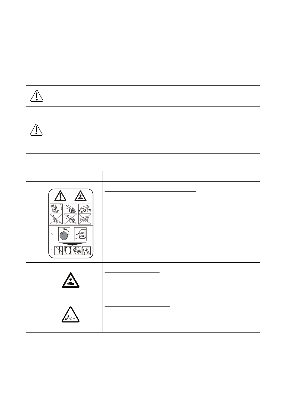
No. Caution indication Description
1
Precaution for sewing machine operation
Indicates that removing the safety and operating the sewing
machine for some other purposes with power-on are prohibited.
Please do not operate the sewing machine without
protective equipment such as a needle guard, an eye guard,
:
a belt cover or the others.
Please turn off the power switch when threading, changing
a needle and a bobbin, cleaning, and lubricating.
2
3
Caution for fingers injury
Indicates a possibility of fingers (hands) injury in a certain
condition.
Caution for squeezing fingers
Indicates a possibility of squeezing fingers in a certain condition.
:
:
Page 3

SAFETY PRECAUTIONS
DANGER
To prevent from receiving an electric shock, always turn off a power switch and unplug power supply
when opening a control box, and then open after ten minutes passes.
CAUTION
USAGE ENVIRONMENT
Please do not operate the sewing machine under the following conditions.
(1) In the ambient temperature of 35 degrees (95°F) or more than 35 degrees, or the ambient
temperature of 5 degrees or less than 5 degrees (41°F).
(2) In the ambient temperature of 55 degrees (131°F) or more than 55 degrees, or the ambient
temperature of -10 degrees or less than -10 degrees (18°F) during transportation.
(3) In the relative humidity exceeding 85% or less than 45%.
(4) In the open-air place or the location that receives direct sunlight.
(5) In the place near heat sources such as heating devices.
(6) In the atmosphere filled with dust, explosive gas, or corrosive gas.
(7) In the place where the fluctuation in the power voltage of 10% or more than 10%, or the power
voltage of -10% or less than -10% of the fixed power voltage.
(8) In the place where the power source cannot supply enough voltage to keep the motor running.
(9) In the place filled with strong electric noises such as high-frequency welders.
INSTALLATION
(1) Please have some specialists, who have enough experience for the sewing machine installations,
install the sewing machine.
(2) Please have a qualified electrician perform necessary electric wiring.
(3) Please do not operate until the sewing machine is repaired when any damage or fault is found on
the sewing machine at the installation.
(4) Please do not refurbish the sewing machine.
(5) The sewing machine is heavy. For the safety, please make sure to install the sewing machine head
by more than one person.
(6) Please make sure to fit the safety protective equipment (the motor cover or the others) and the
accessory protective equipment (the eye guard) that removed temporarily for installation.
Page 4

SEWING
(1) Please make sure to turn the power switch off before installing or replacing needles.
(2) Please pay attention for the fingers not to be injured by the needle point.
(3) Please make sure to turn power switch off before lubricating.
(4) Please pay attention that oil does not get on your skin or in your eyes as it may cause an
inflammation.
(5) Please make sure to keep oil out of the reach of children who may drink oil by mistake.
(6) Please make sure to turn the power switch off before threading a needle.
(7) Before starting the sewing, please make sure the position and the function of the halt switch.
(8) Please do not touch the operating parts during sewing operation.
(9) It is very dangerous to operate the sewing machine without safety guards (eye guards, belt covers,
link covers, finger guards or the others).
Please make sure to operate the sewing machine with safety guards.
(10) Please make sure to turn the power switch off when stopping the sewing machine temporarily.
ADJUSTMENT
(1) Please make sure to turn the power switch off before adjusting the sewing machine.
(2) If the adjustment is required while the power switch on, do not step on the foot switch by mistake.
(3) Please be careful not to be injured by a sharp part such as the needle and the shuttle hook point.
(4) Please make sure to put the safety guards (eye guards, belt guards, link covers, and finger guards
or the others) back on the initial position after the sewing machine adjustment.
Page 5

CONTENTS
1. STRUCTURE OF THE SEWING MACHINE····································
2. SPECIFICATION·······································································
3. INSTALLATION········································································
3-1. Installation of the foot switch····································································
3-2. Connection of the air tube·······································································
3-3. Installation of the thread stand·································································
3-4. Installation of the eye guard····································································
3-5. Installation of the spindle motor································································
4. LUBRICATION·········································································
41. Filling the oil tank···················································································
42. Oiling··································································································
5. PROPER OPERATION······························································
1
2
3
3
3
4
4
5
6
6
6
7
5-1. Initial setting of the control box·································································
5-2. Installation of the needle·········································································
5-3. Threading the upper thread·····································································
5-4. Winding the bobbin thread······································································
5-5. Setting the bobbin·················································································
5-6. Setting the bobbin case··········································································
6. SEWING·················································································
6-1. The sewing operation············································································
6-2. Operation of the halt switch·····································································
6-3. Adjustment of the thread tension······························································
6-4. Operation of the presser foot 2-stage lifting device·······································
6-5. Adjustment of the lifting volume································································
7
7
8
9
10
10
11
11
12
13
14
15
Page 6

7. STANDARD ADJUSTMENT························································
7-1. Adjustment of the needle bar position························································
7-2. Adjustment of the position between the needle and the shuttle hook················
7-3. Adjustment of the clearance between the shuttle hook and the needle··············
7-4. Adjustment of the clearance between the driver and the needle······················
7-5. Adjustment of the shuttle race thread guide················································
7-6. Adjustment of the presser foot·································································
7-6-1. Adjustment of the presser foot position·················································
7-6-2. Adjustment of the presser foot lift during the sewing································
7-6-3. Adjustment of the presser foot timing····················································
7-7. Adjustment of the wiper··········································································
7-8. Adjustment of the bobbin winder······························································
7-9. Adjustment of the work holder·································································
7-9-1. Adjustment of the work holder pressure················································
7-9-2. Changing the work holder··································································
7-10. Adjustment of the trimmer cam follower····················································
16
16
16
17
18
19
19
19
21
22
23
24
24
24
24
25
7-11. Adjustment of the position of movable knife···············································
7-12. Adjustment of the blade drive arm spring force··········································
7-13. Adjustment of the fixed knife position·······················································
7-14. Adjustment of the thread take up spring swing stroke··································
7-15. Adjustment of the thread take up spring tension·········································
7-16. Adjustment of the thread tail after the trimming··········································
7-17. Adjustment of the upper thread tension release ·········································
7-18. Adjustment of the mechanical home position·············································
7-18-1. Adjustment of the X direction····························································
7-18-2. Adjustment of the Y direction····························································
7-19. Adjustment of the X-Y timing belt tension··················································
7-19-1. Adjustment of the X timing belt tension················································
7-19-2. Adjustment of the Y timing belt tension················································
8. MAINTENANCE·······································································
8-1. Cleaning·····························································································
26
26
27
28
28
28
29
30
31
32
33
33
34
35
35
8-2. Disposing of oil waste············································································
9. TROUBLESHOOTING·······························································
35
36
Page 7
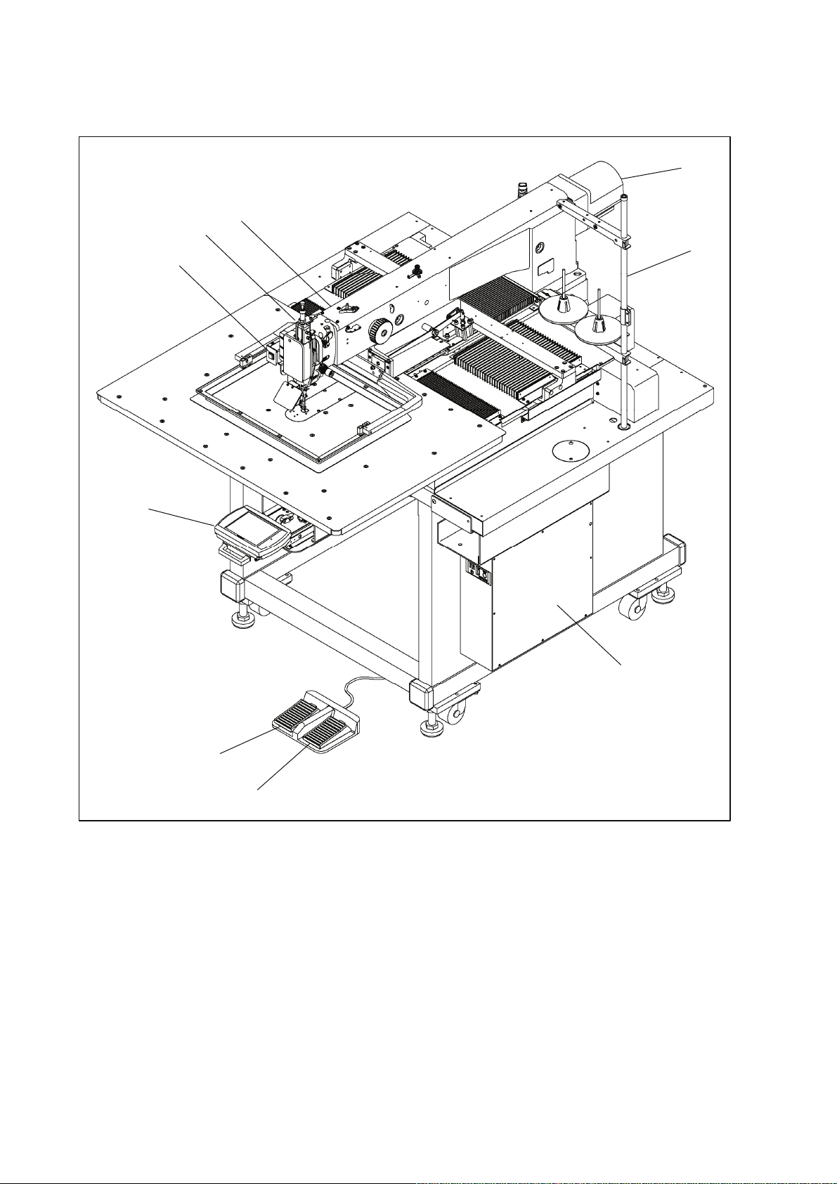
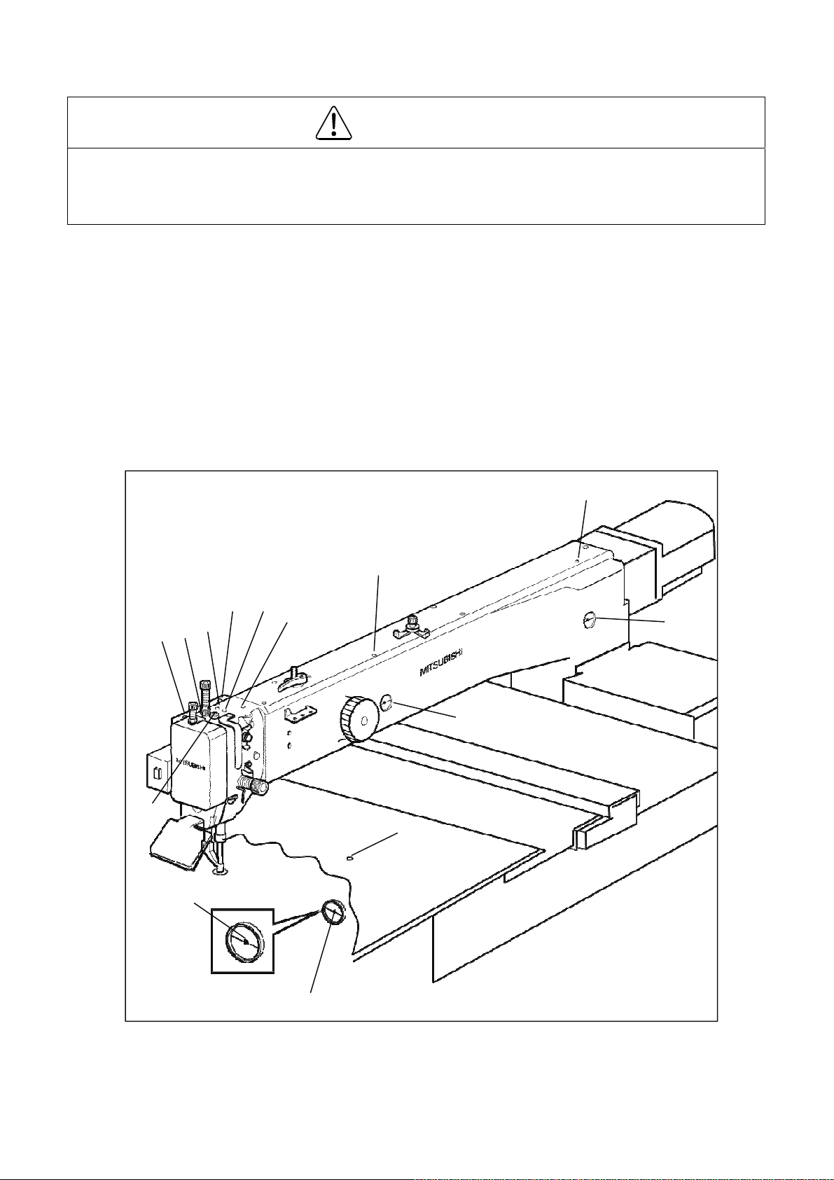
1. STRUCTURE OF THE SEWING MACHINE
PLK-G4030/G6030 electronic pattern sewing machine consists of the following main parts.
<3>
<5>
<1>
<9>
<2>
<8>
<1>: Sewing machine head <2>: Main shaft motor <3>: Halt switch <4>: Control box
<5>: Operation panel <6>: Work holder foot switch <7>: Start foot switch <8>: Thread stand
<9>: Presser foot 2-stage lifting device
<7>
<6>
<4>
- 1 -
Page 8

2. SPECIFICATIONS
Model PLK-G4030 PLK-G6030
Sewing area
Maximum sewing speed 2,000rpm
Setting speed 10 speed levels in 200 rpm to 2,800 rpm
Stitch length 0.1 to 20.0 mm
Stitch type Single needle lock stitch
Maximum number of needles 20,000 per pattern
Storable sewing data item 520 patterns (internal memory)
Data memory Internal memory, USB memory
Needle bar stroke 41.2 mm
Thread take up lever stroke 68 mm
Class of needle DPX17#18 (at standard installation)
Wiper system Back to front wiping system
Presser foot lift *1 15 mm (12 mm as factory default setting)
Presser foot stroke *2 In 4 mm to 10 mm (4 mm as factory default setting)
Work holder lift 30 mm
X-direction (left/right) 400 mm X-direction (left/right) 600 mm
Y-direction (front / back) 300 mm
Hook Large size shuttle hook
Bobbin case With non racing spring
Bobbin Aluminum bobbin
Thread trimmer system Horizontal engagement with fixed knife and movable knife
Lubrication system Manual oiling and replenishment with the oil braids from the oil tanks
Lubrication oil Pulley SF oil
X-Y drive system
Machine dimensions
(W)x(L)x(H)
Weight Total 420 Kg Total 440Kg
Type of motor XL-K756-20
Type of controller PLK-G-CU-20
Type of operation panel PLK-G-PAL-2
Power
Stepping motor feedback control
Timing belt drive system. Intermittent or continuous feeding
1,185mm x 1,572mm x
1,234mm
The power in 110V to 120V or in 380V to 415V is compatible with
power unit (option)
1,350mm x 1,572mm x
1,234mm
*1:Presser foot lift is the height of the presser foot after the sewing has stopped.
*2:Presser foot stroke is the up and down movement of the presser foot while sewing.
- 2 -
Page 9
3. INSTALLATION
CAUTION
(1) Please have some specialists, who have enough experience for the sewing machine installations,
install the sewing machine.
(2) Please have a Qualified Electrician perform necessary electric wiring.
(3) Please do not operate until the sewing machine is repaired when any damage or fault is found on the
sewing machine at the installation.
(4) Please do not refurbish the sewing machine.
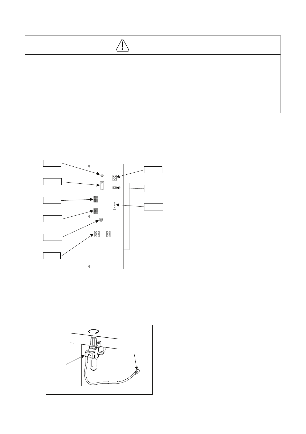
3-1. Installation of the foot switch
Connect the foot switch to the connector CON H.
The foot switch is enclosed in the accessory box.
CON A
CON E
CON F
CON G
CON H
CON J
CON B
CON C
CON D
CON A: Operation panel
CON B: Power supply
CON C: Various solenoid DC power
CON D: Spindle motor
CON E: Various solenoid
CON F: Spindle encoder
CON G: X-Y spindle encoder
CON H: Foot switch
CON J: X-Y spindle stepping motor
3-2. Connection of the air tube
Insert the one end of the air tube (8mm Diameter) into the intake air fitting of the filter regulator (No.1)
then, join the other end of the air tube with the suitable air coupling to be adopted with the air supply
source provided in your factory. One of the air couplings (No.2) is enclosed in the accessory box.
<1>
①
<2>
②
- 3 -
<1>: Intake air fitting
<2>: Air coupling
Page 10
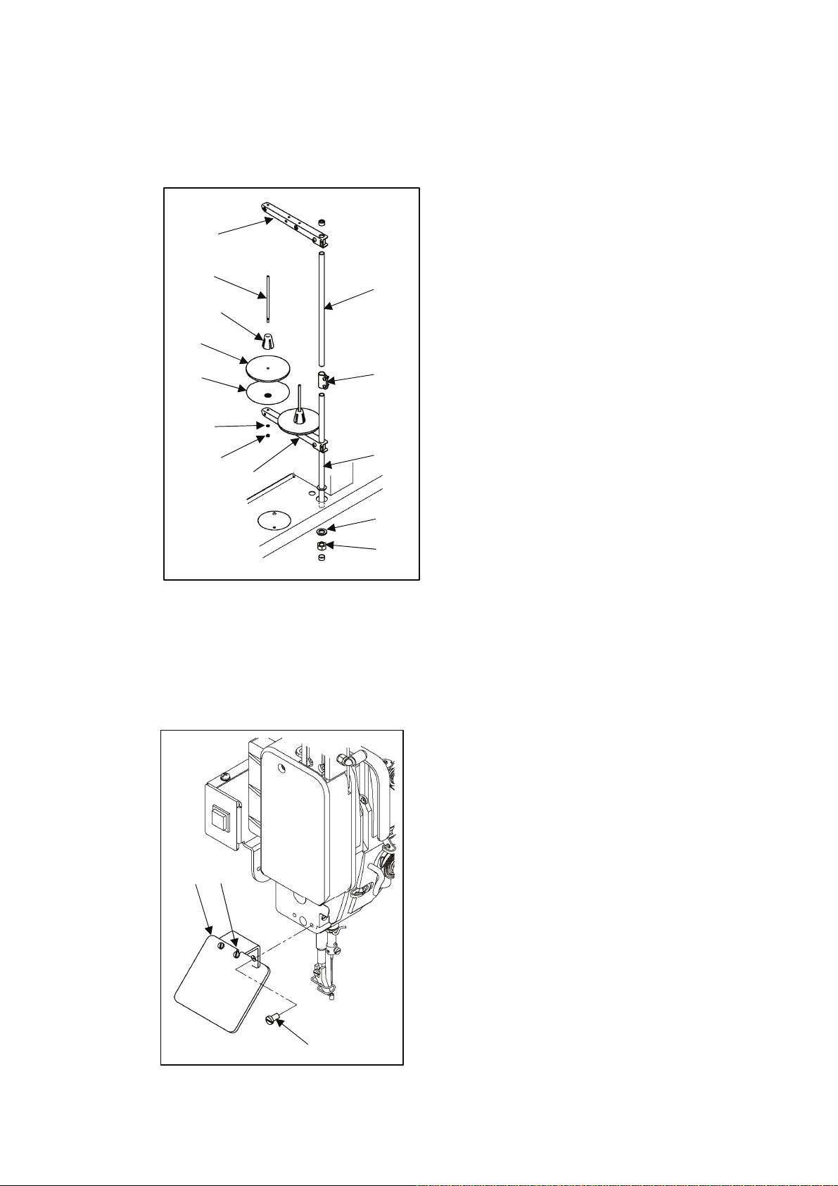
3-3. Installation of the thread stand
(1) Assemble the parts (No.1 to No.11) of the thread stand as shown on the figure.
(2) Fit the thread stand into the hole at the far right on the table stand with the nut (No.13) and the
washers (No.12).
<9>
<6>
<4>
<3>
<7>
<5>
<8>
<1>
<11>
<2>
<10>
<12>
<13>
<1>: Upper column pipe
<2>: Lower column pipe
<3>: Spool stand base (two stand bases)
<4>: Spool mat (two mats)
<5>: Spool holder (two holders)
<6>: Spool shaft (two shafts)
<7>: Spring washer (two washers)
<8>: Nut (four nuts)
<9>: Thread hunger
<10>: Spool holder
<11>: Column joint
<12>: Washer
<13>: Nut
3-4. Installation of the eye guard
(1) Loosen the screws (No.2) on the eye guard unit (No.1) then, mount the screws (No.3) to the flat place
of the sewing machine with the open guard.
(2) Return the open guard to the initial position then, tighten the screws (No.2).
<1>
<2>
<1>: Eye guard unit
<2>: Screw
<3>: Screw (two screws)
<3>
- 4 -
Page 11
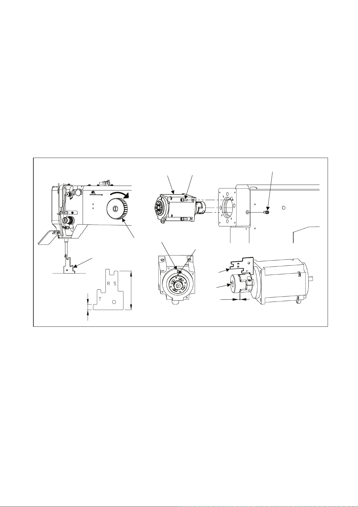
3-5. Installation of the spindle motor
(1) If the spindle motor (No.1) has been removed from the machine for the adjustment or the like, fix the
spindle motor as the procedure described below.
(2) Set the pin (No.3) position of the bushing to the motor mark (No.2).
(3) Adjust the clearance between the motor and the coupling (No.4). Use the part measuring 7mm on the
gauge (No.5). Position Bolt “A” (No.6) in the below described position when reinstalling the coupling to
the machine top shaft. Make sure the clearance of the coupling is from 2.0 to 3.2mm.
(4) Turn the pulley (No.8) in the direction of the arrow then, slip the gauge (No.5) in between the needle
bar and the needle plate. Use the part of S side (50.1mm) on the gauge.
(5) Be careful not to make the motor turn and fit the coupling to the upper shaft, and then tighten the bolt
A (No.6) first and the bolt B (No.7) second.
<1>
<7>
<6>
<5>
<8>
<2>
<3>
<5>
<4>
2.0~3.2mm
7
<1>: Spindle motor <2>: Motor mark <3>: Pin <4>: Coupling <5>: Gauge <6>: Bolt A
<7>: Bolt B <8>: Pulley
- 5 -
Page 12
4. LUBRICATION
CAUTION
(1) Please make sure to turn power switch off before lubricating.
(2) Please pay attention that oil does not get on your skin or in your eyes as it may cause an inflammation.
(3) Please make sure to keep oil out of the reach of children who may drink oil by mistake.
[Notice] Please make sure to lubricate when operating for the first time after the installation. Also, please
make sure to check the amount of oil when the machine has not been used for a long time.
4-1. Filling the oil tank
Pour the oil through the oil hole (No.1 and 3) to the oil tank (No.2 and 4) on the machine arm. Pour
the oil hole (No.5) to the oil tank (No.6) on the machine bed. Please fill with the oil over level mark
(No.7) of the oil tank.
4-2. Oiling
Put some oil to the red marked oil holes (No.8 ~ 14).
<1>
<8>
<14>
<9>
<11>
<10>
<12>
<13>
<3>
<2>
<4>
<5>
<7>
<6>
- 6 -
Page 13
5. PROPER OPERATION
5-1. Initial setting of the control box
When using the sewing machine for the first time, the model and the language of the sewing machine in
use have to be set.
Refer to the instructions in the paragraph “[6] Initial Setting of System (Model/language Setting)” in the
CONTROL UNIT technical manual.
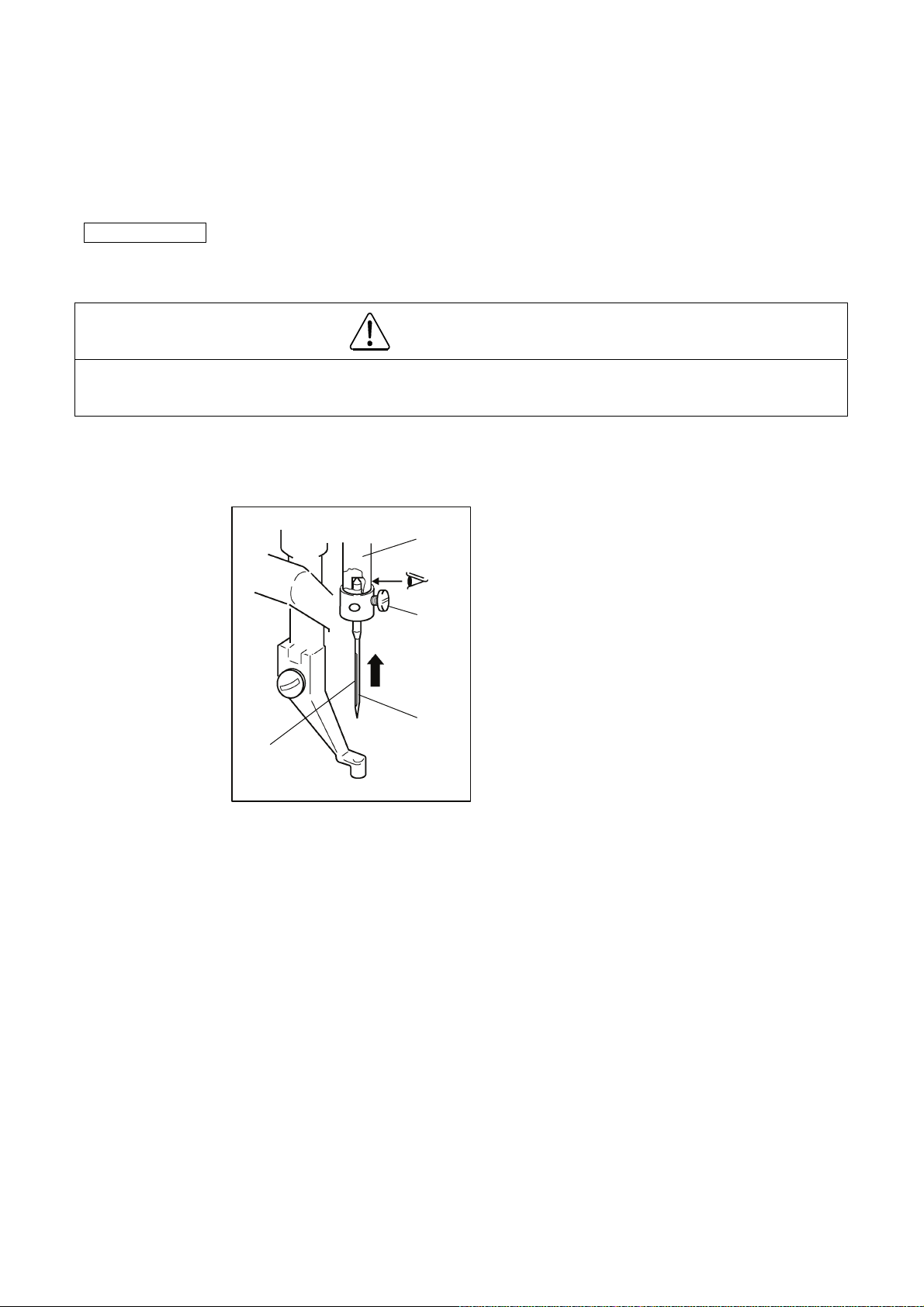
5-2. Installation of the needle
CAUTION
(1) Please make sure to turn the power switch off before installing or replacing needles.
(2) Please pay attention for the fingers not to be injured by the needle point.
(1) Loosen the set screw (No.1) then, insert a new needle (No.2) until the needle head is reached the end
of the hole of the needle bar (No.3).
(2) Tighten the set screw (No.1) with facing the needle groove (No.4) to the front.
<3>
<1>
<1>: Set screw
<2>: Needle
<3>: Needle bar
<4>: Needle groove
<2>
<4>
- 7 -
Page 14
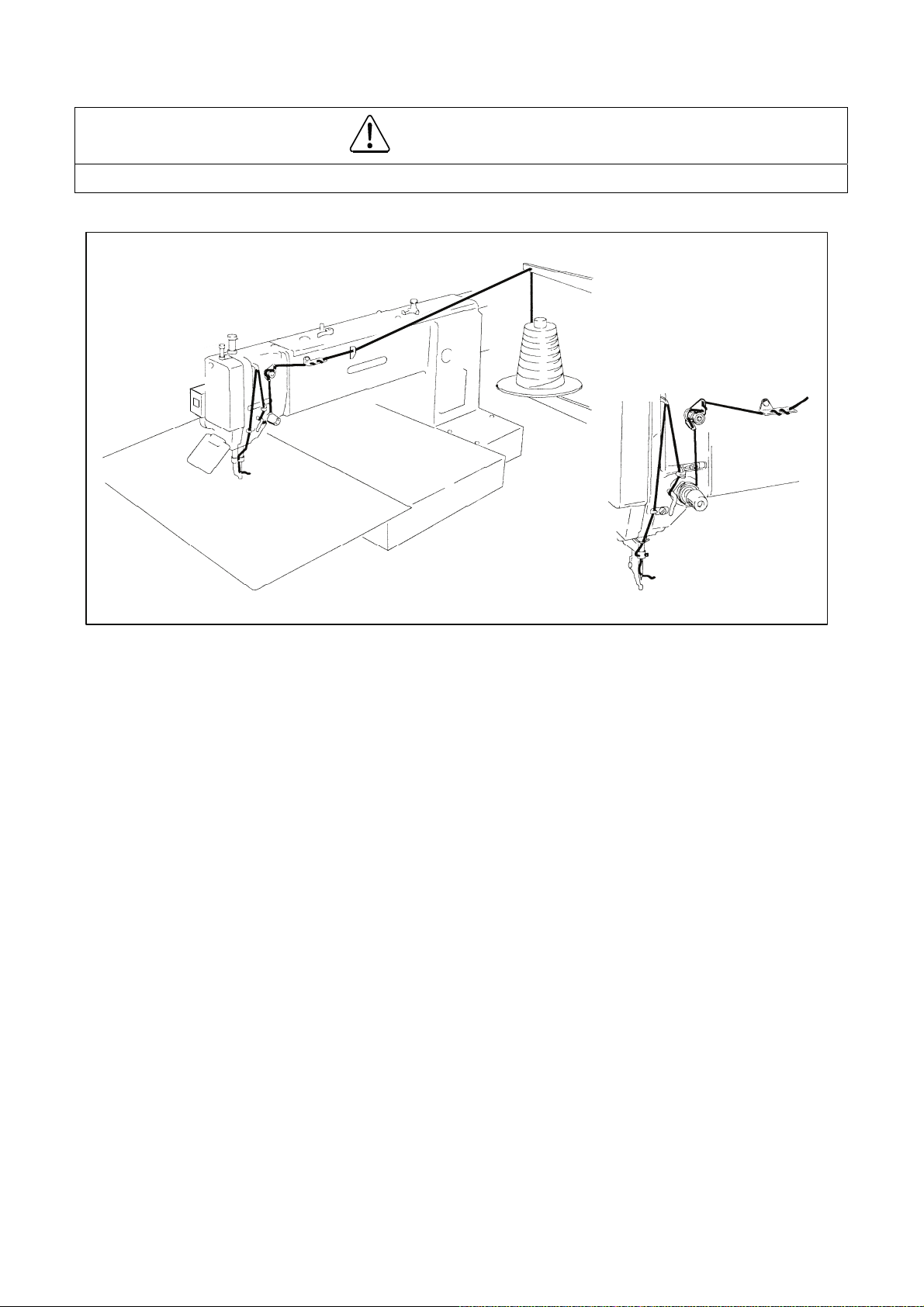
5-3. Threading the upper thread
CAUTION
(1) Please turn the power switch off when threading a needle.
Thread the upper thread as shown on the figure.
- 8 -
Page 15

5-4. Winding the bobbin thread
CAUTION
(1) Please do not touch the rotating part during winding thread. Doing so may cause injury and/or the
machine failure.
[Notice] Please make sure to pull the upper thread out of the needle before winding the bobbin thread.
(1) Route the thread as shown in the below figure then, wind the thread to the bobbin (No.1) in the
direction of “a” arrow several times. Then fit the bobbin to the bobbin winder (No.2) and push in the
bobbin presser arm (No.3).
(2) With the machine in the Bobbin Wind Mode, step on the work holder foot switch first and then the start
switch second so that the thread continues winding to the bobbin while the start switch is stepped on.
(3) When the bobbin finishes winding a certain amount (80 to 90 % of the outside diameter of bobbin) of
thread, the bobbin presser arm is returned to the initial position.
(4) To wind the bobbin thread during the sewing operation, carry out the procedure (1) above then, the
bobbin winding is performed automatically.
For the bobbin winding mode, refer to the instructions in the paragraph “[3] Explanations of basic
screen, icons and operation “5. The Bobbin Winding screen” is explained below” in the
OPERATION PANEL technical manual.
2
<2>
3
<1>
4
<3>
6
5
1
<1>: Bobbin <2>: Bobbin winder <3>: Bobbin presser arm
- 9 -
Page 16

5-5. Setting the bobbin
(1) Insert a full Bobbin (No.2) into the bobbin case (No.1).
(2) Pull out the bobbin thread (No.3) from the slit (No.4) and pass the thread through the thread hole
(No.5). When the bobbin thread is pulled, the pin rotates in the arrow direction shown on the figure. If
the pin starts rotating to the opposite direction, turn the bobbin over and reset the bobbin.
<4>
<5>
<3>
<2>
<1>
<1>: Bobbin case
<2>: Bobbin
<3>: Thread
<4>: Bobbin case slit
<5>: Bobbin case thread hole
5-6. Setting the bobbin case
(1) Pull the bobbin thread about 2.5cm out of the thread hole of the bobbin case.
(2) Open the cylinder cover (No.1).
(3) Open the bobbin case latch (No.2) and hold it then, fit it securely in the shuttle hook (No.3).
<3>
2.5cm
<2>
<1>: Cylinder cover
<2>: Bobbin case latch
<3>: Shuttle hook
<1>
- 10 -
Page 17

6. SEWING
CAUTION
(1) Before starting the sewing, please make sure the position and the function of the halt switch.
(2) Please do not touch the operating parts during sewing operation.
(3) It is very dangerous to operate the sewing machine without safety guards (eye guards, belt covers,
link covers, finger guards or the others). Please make sure to operate the sewing machine with safety
guards.
(4) Please make sure to turn the power switch off when stopping the sewing machine temporarily.
6-1. The sewing operation
(1) Turn the power switch on.
(2) Press the home position return icon .
(3) Select a sewing data.
Press the on the standard screen then, press the .
(4) Select a target (internal memory/USB memory) to read the data from.
The screen as default setting is set to the reading from internal memory mode.
(The mode display at the left top on the screen is .)
Press the ,when switching the reading from the internal memory to the reading from USB
memory mode.
(Pressing the also can switch the target.)
Press the to switch the page with full of data.
(5) Select a data then, set the data.
Press the target data number then, press the .
(6) Set the sewing speed.
Set the appropriate sewing speed by selecting or . (10 selections of 0 to 9)
(7) Set the sewing material under the work holder.
(8) When the black foot switch is stepped on, the work holder goes down.
(When the sewing material has to be reset, step the black color foot switch again to make the work
holder go up.)
(9) Step on the gray color start switch so that the sewing machine starts sewing,
(10) After the sewing finishes, the work holder is lifted automatically then, the sewing material is released.
- 11 -
Page 18

6-2. Operation of the halt switch
(1) If accidents such as a thread breakage, needle breakage and others
happened during the sewing, press the halt switch immediately.
The sewing machine stops instantly.
(2) To cancel the halt state, press the halt switch again.
(3) When continuing sewing, step on the grey foot switch to restart at the
halted position. (Press the jogging in forward/reverse direction icon so
that the sewing start position will move.)
(4) To cancel sewing, press the home position return icon .
<1>
<1>: Halt switch
- 12 -
Page 19

6-3. Adjustment of the thread tension
(1) Adjustment of bobbin thread tension
Adjust the bobbin thread tension with the thread tension
adjusting screw (No.2) on the bobbin case (No.1). The thread
tension becomes loose when loosening the thread tension
adjusting screw (No.2) counterclockwise, and the thread
tension becomes tight when tightening the thread tension
adjusting screw clockwise.
(2) Adjustment of upper thread tension
Adjust the upper thread tension corresponding to the bobbin
Thread tension. The upper thread tension becomes tight when
tightening the thread tension adjusting nut (No.1) clockwise,
and the upper thread tension becomes loose when loosening
the thread tension adjusting nut counterclockwise.
<1>
<2>
<1>: Bobbin case
<2>: Thread tension adjusting screw
<1>: Thread tension adjusting nut
<1>
- 13 -
Page 20

6-4. Operation of the presser foot 2-stage lifting device
To operate the Presser Foot 2-Stage Lifting Device, use the Function Code 2 (FUN2) in the
process of pattern input.
<Example>
An example of operations to add function code 2 using the operation panel is explained below.
This section describes the methods for input the code data with the input mode when newly
creating a pattern, Please refer to the technical data "Operation Panel Section" enclosed with the
operation panel for details.
(1) Press the on the standard screen.
(2) Press the and open the Input Mode
screen.
(3) Input the dry feed data and stitching data, etc.,
and press at the position where the
"presser foot two-step changeover unit" is to be
activated (the position where the FUN2 code is
to be input).
- 14 -
Page 21

(4)The screen for selecting the codes will open, so
select , and then press .
Input the subsequent pattern data after that.
(5) Press the ( ) after inputting the pattern
data. And then check that the "FUN2" code has been input.
A
6-5. Adjustment of lifting volume
(1) When the nut (No.2) is loosened and the dial
screw (No.1) is turned counterclockwise, the
rise amount will increase, and when turned
clockwise, the rise amount will decrease.
(2) After adjusting, securely tighten the nut (No.2).
CAUTION
Adjust the presser foot changeover rise
amount between 0 and 8mm. Failure to
do so could result in trouble.
<1>
<2>
- 15 -
Page 22

7. STANDARD ADJUSTMENT
CAUTION
(1) Please make sure to turn the power switch off before adjusting the sewing machine.
(2) When adjusting the sewing machine with the power switch on, please be careful not to step on the
foot switch by mistake.
(3) Please be careful not to be injured by a sharp part such as the needle and the shuttle hook point.
(4) Please make sure to put the safety guards (eye guards, belt guards, link covers, and finger guards or
the others) back on the initial position after the sewing machine adjustment.
7-1. Adjustment of the needle bar position
(1) Turn the power switch off then, stop the needle bar (No.1) at the lowest position.
(2) Move the needle bar to the position where the needle bar timing mark A is matched to the needle bar
bushing (No.4) bottom line. (For the needle class DP×17)
(3) If the position of the needle bar timing mark A is not matched to the needle bar bushing bottom line,
remove the rubber plug (No.2) from the face cover then, loosen the needle bar holder set screw
(No.3).
(4) For the needle class DP×5, move the needle bar to the position where the needle bar timing mark B is
matched to the needle bar bushing bottom line.
Timing mark A: For the needle class DP×17
Timing mark B: For the needle class DP×5
<4>
<2>
<3>
<1>
7-2. Adjustment of the position between the needle and the shuttle hook
(1) Turn the power switch off. Move up the needle bar (No.1) from the lowest position then, stop the
needle bar at the position where the needle bar timing mark C is matched to the needle bar bushing
(No.2) bottom line. (For the needle class DP×17)
(2) Open the cylinder cover (No.3).
(3) Remove the bobbin case (No.4).
(4) Turn the hook retainer arm (No.5) then, remove the hook retainer (No.6).
(5) Adjust the shuttle hook (No.7) point to match with the center line of the needle (No.8). The matched
position is standard.
- 16 -
Page 23

(6) If the shuttle hook point is not matched with the center line of the needle, loosen the driver (No.9) set
screw (No.10) then, turn the shuttle hook and the driver for the adjustment.
(7) For the needle class DP×5, move the needle bar to the position where the needle bar timing mark D is
matched to the needle bar bushing bottom line then, carry out the same procedure as described
above.
<2>
<1>: Needle bar <2>: Needle bar bushing <3>: Cylinder cover <4>: Bobbin case <5>: Shuttle hook
retainer arm <6>: Hook retainer <7>: Shuttle hook <8>: Needle <9>: Driver <10>: Set screw
<1>
<7>
C : For the needle class DP X 17
D : For the needle class DP X 5
<4>
<6>
<8>
<3>
<10>
<5>
<9>
7-3. Adjustment of the clearance between the shuttle hook and the needle
(1) Take the same procedure described in (1) to (4) of above paragraph 7-2.
(2) Set the clearance between the shuttle hook (No.1) point and the needle (No.2) in 0.05 to 0.1mm,
standard position.
(3) Loosen the shuttle race set screw (No.3) and turn the eccentric pin (No.4) to move the hook entirely
back and forth for adjustment. Adjust the clearance to be standard.
<2>
③
<3>
④
<4>
②
①
<1>
0.05~0.1mm
<5>
⑤
<1>: Shuttle hook <2>: Needle <3>: Shuttle race set screw <4>: Eccentric pin
<5>: Cylinder cover
- 17 -
Page 24

7-4. Adjustment of the clearance between the driver and the needle
(1) Please take the same procedures as above paragraph 7-2. from (1) to (5).
(2) Please make sure the clearance between the shuttle hook point and the needle has been adjusted
0.05~0.1mm at above procedure 7-3 Adjustment of the clearance between the shuttle hook and the
needle.
(3) Loosen the driver setscrew (No.1) and turn the eccentric pin (No.2) so that the clearance between
the driver (No.3) and the needle (No.4) can become 0.05~0.1mm.
4
0.05~0.1mm
1
2
3
<1>: Driver set screw <2>: Eccentric pin <3>: Driver <4>: Needle
5
- 18 -
Page 25

7-5. Adjustment of the shuttle race thread guide
(1) Remove the E-shaped snap ring (No.3) which is engaging the movable knife (No.2) and the link
(No.1) then, loosen the setscrews (No.4) and remove the sliding plate (No.5).
(2) Loosen the setscrews (No.10) and move the thread guide (No.6) to the position where the needle
center line (No.8) divides the needle groove (No.7) evenly and the rear side line (No.9) of the needle
is aligned with the shoulder (No.9) of the thread guide (No.6). At this time, make sure that there is
some clearance between the hook retainer and the thread guide (No.6) at least the upper thread can
be passed smoothly through it (standard clearance is 0.8mm).
If this clearance is too wide, it causes the trimming failure and if this clearance is too narrow, it causes
the sewing condition disturbance, the trimmed upper thread tail uneven and the locking up the hook
with the upper thread.
(3) After the adjustment, engage the link (No.1) of the trimmer mechanism with the movable knife (No.2)
with the E-shaped snap ring (No.3) and put the sliding plate (No.5) back on the original location then,
tighten the setscrews (No.4). At this time, set the sliding plate (No.5) so that the needle (No.11) can
come down to the center (No.12) of the needle hole of the needle plate.
7-6. Adjustment of the presser foot
NOTE The presser foot is a very important part to form the fine stitches. It moves simultaneously with
the needle and stabilize the needle penetrating area of the sewing material with pressing down
it, when the needle sticks into or pulls out the sewing material and prevent the skip stitch or the
over penetration happening Please adjust the presser foot properly to the sewing materials
with the following instructions.
7-6-1. Adjustment of the presser foot position
NOTE Please always adjust the presser foot position when the thickness of the sewing material is
changed.
- 19 -
Page 26

(1) Turn the power switch OFF.
(2) Remove the face plate (No.1) and the cover (No.2).
(3) Turn the sewing machine pulley by hand and stop the needle bar (No.3) at the lowest position. At this
time, make sure the setscrew (No.5) of the eccentric cam (No.4) is positioned right beside the center
line of the upper shaft. This is the standard position of the eccentric cam (No.4).If the eccentric cam
(No.4) is off from this position, set it back to the standard position with the instructions in the paragraph
[7-6-3. Adjustment of the presser foot timing] in the following page.
(4) Turn the sewing machine pulley by hand and stop the needle at the highest position (this is also the
thread take up lever's highest position).At this time, loosen the setscrew (No.9) of the upper feed lock
crank shaft (No.8) and adjust the center line of the bell crank (No.6) to be parallel with the presser foot
bar (No.7).
(5) Insert the sewing material (No.10) under the work holder (No.11) and turn the sewing machine pulley
by hand then, stop the presser foot (No.12) at the lowest position.
(6) Loosen the presser foot bar setscrew (No.14) and move the presser foot bar (No.7) then, adjust the
presser foot (No.12) position to be become the clearance between the bottom surface of the presser
foot (No.12) and the surface of the sewing material (No.13) 0~0.5mm. At the same time, rotate the
presser foot bar (No.7) for the needle (No.15) to come down to the center of the needle hole of the
presser foot (No.12).
(7) After the adjustment, put the face plate (No.1) and the cover (No.2) back on the original location.
NOTE The lower position of the presser foot, the more effective for the skip stitches. However, if the
presser foot becomes to press the sewing material, the movement of the presser foot mechanism
generates a slight noise. And also, the presser foot stays longer to hold the sewing material, so
the upper thread tension becomes loose or the sewing pattern forming gets out of shape because
the presser foot catches the surface of the sewing material. For avoiding these troubles, please
lower the presser foot as small as possible.
- 20 -
Page 27

NOTE If the thickness of the sewing material changes very often, it is recommended to take the easy way
for the adjustment of the presser foot position with the method that change only the fixed position
of the presser foot after fixed the presser foot bar at higher position.
For this adjustment, loosen the setscrew (No.16) then, move the presser foot (No.12) up and down.
7-6-2. Adjustment of the presser foot lift during the sewing
NOTE The presser foot lift during the sewing can be adjusted 0 and 2~10mm.
(1) The presser foot lift during the sewing becomes 4~10mm at the condition which the connection of
the link (No.2) and the lever (No.3) with the shoulder screw (No.1) is as shown on the figure and it
becomes 2~4mm if the connection is made with A hole, and it becomes 0mm if the connection is
made with B hole.
(2) The stepping lift is adjusted 4mm when the sewing machine is shipped from the factory.
(3) For the adjustment at the each range of the presser foot lift, remove the cover (No.4) then, loosen
and move the adjust bolt (No.5).
(4) If the link (No.2) connection is changed to A or B hole, the presser foot position is also changed. So
reset the presser foot position with adjusting the position of the presser foot bar or the presser foot
itself with loosing their setscrews (No.6) or (No.7).
(5) Regarding the running noise and the vibration, the higher lift effects worse. So adjust the presser
foot lift during the sewing as small as possible.
(6) After the adjustment, put the cover (No.4) and the face plate (No.8) back on the original location.
- 21 -
Page 28

7-6-3. Adjustment of the presser foot timing
NOTE The presser foot up and down movement during the sewing synchronizes with the needle up and
down movement. With changing this synchronized timing to the sewing materials, the skip stitches
can be prevented or the seam tightness can be improved.
For example, the delay of the presser foot timing against the needle movement prevents the skip
stitches especially to the thin materials, and the advance of the presser foot timing can improve
the seam tightness especially to the thick materials.
(1) Remove the cover (No.1).
(2) Loosen the setscrew "C" of the eccentric cam (No.2).
(3) Turn the sewing machine pulley by hand and stop the needle bar (No.3) at the lowest position. At
this stage, the setscrew "A" of the eccentric cam (No.2) is positioned right beside the center line of the
upper shaft. This is the standard position for the eccentric cam (No.2).
(4) Loosen the setscrew "A" of the eccentric cam (No.2).
(5) Hold the eccentric cam (No.2) and turn the sewing machine pulley slowly by hand. If turn the sewing
machine pulley to the arrow direction "D", the presser foot timing against the needle movement is
delayed, and if turn the pulley to the opposite direction, the timing of the presser foot is advanced.
(6) After the adjustment, tighten the setscrew "A" and "C" in turn with slightly pushing the eccentric cam
(No.2) to the arrow direction "E".
(7)Put the cover (No.1) back on the original location.
- 22 -
Page 29

7-7. Adjustment of the wiper
(1) Loosen the wiper setscrew (No.3) and adjust the wiper (No.1) to be positioned where the wiper
(No.1) passes under the needle point (No.2) with about 2mm clearances right after the sewing
machine is stopped running at the needle upper position (the thread take up lever's highest position).
NOTE When the presser foot position or the presser foot lift is changed, the wiper (No.1) may collide
with the presser foot (No.4). In that case, please do not use the wiper (No.1).
(2) When the wiper function is not be used (not able to be used), set the following.
Set the wiper function to off.
Press the on the standard screen to open the MENU mode.
(3) Press the > > [Wiper ON/OFF] in order.
(4) Select the on the [Wiper ON/OFF] screen, and press the .
- 23 -
Page 30

7-8. Adjustment of the bobbin winder
(1) Adjustment of the winding volume
Adjust the amount of the winding thread with the subsidiary arm (No.1).
The winding volume is adjusted 80% of the full volume when the sewing machine is shipped from the
factory.
(2) Adjustment of the proper position of the bobbin winder
Firstly, loosen the setscrews (No.2) and (No.3) of the bobbin winder and put the empty bobbin (No.4)
on the rotating shaft (No.5) then, push the adjusting lever (No.6) to the arrow direction "a". Secondary,
move the whole bobbin winder to the arrow direction "b" and stop it at the position where the empty
bobbin is rotated then, tighten the setscrews (No.2) and (No.3) of the bobbin winder. This is the
proper position of the bobbin winder.
<4>
<2>
a
<5>
<1>
7-9. Adjustment of the work holder
7-9-1. Adjustment of the work holder presser
The work holder presser is generated by air pressure.
Control the air pressure with the adjusting knob (No.1) of
the air regulator located underneath the table.
If turn the adjusting knob (No.1) to the clockwise, the air
pressure is increased and the work holder pressure Is also
increased simultaneously. If turn the adjusting knob (No.1)
to the counterclockwise, the air pressure is decreased and
the work holder pressure is also decreased
simultaneously.
b
<3>
<6>
390kPa (4kgf/cm2) is the standard air pressure as a
normal sewing operation.
7-9-2. Changing the work holder
(1) Before changing the work holder (No.1), remove the holder block (No.4) that is secured with the
screw (No.3). It will come off by pressing the work holder (No.1) down from the area engaged with
the pin (No.6) of the work holder arm (No.5).
(2) Prepare another work holder and securely engaged its U shaped ditch (No.2) with the pin (No.6) of
the work holder arm (No.5). At this time, make sure that there is no play in the
arrow direction.
- 24 -
Page 31

*
*
Marked parts are only used for PLK-G6030.
*
7-10. Adjustment of the trimmer cam follower
(1) Turn the power switch OFF and remove the top cover.
(2) Under the sewing machine regular stop condition (the needle stop position is upper and the take up
lever stop position is highest), loosen the setscrew (No.5) of the cam follower lever (No.4) and
adjust the cam follower (No.2) to be positioned to contact with the shoulder portion (No.3) of the
trimmer cam (No.1) with having about 1mm clearance between the cam follower (No.2) and the
trimmer cam (No.1). After this adjustment, tighten the setscrew (No.5) of the cam follower lever
(No.4).
(3) Push the cam follower lever (No.4) by hand to the
follower (No.2) is engaged into the cam groove (No.6) smoothly.
(4) If the cam follower (No.2) is not engaged smoothly, under confirming with the condition which the
cam follower (No.2) contacts with the shoulder portion (No.3) of the trimmer cam (No.1), loosen the
nut (No.7) and tighten the stopper screw (No.8) until it touches with the stopper (No.9) of the cam
follower lever (No.4) then, loosen the stopper screw (No.8) back about 1/3 turn and fix the nut
(No.7) firmly.
arrow direction and make sure that the cam
- 25 -
Page 32

7-11. Adjustment of the position for the movable knife point
(1) Proceed as below to adjust the movable knife so that its end coincides with the front of the hook
retainer (No.2).
(2) Remove then slide plate, and open the cylinder cover.
(3) Check with the point (No.1) of the movable knife whether it is located at the position apart 0.5mm
from the front face of the hook retainer (No.2).
(4) For the adjustment of the movable knife point (No.1), loosen the adjusting screw nut (No.3,4) and
move the rod end (No.5) right and left then, adjust the position of the movable knife point.
(5) After the adjustment, tighten the adjusting screw nut (No.3,4) securely.
7-12. Adjustment of the blade drive arm spring force
(1) Remove the belt cover at the motor side
and detach the V-belt.
(2) Remove the screw of the oil pan at the
front. And slide the oil pan to front side.
(3) Turn the pulley by hand to needle down
position, Push the cam follower lever by
hand. And turn pulley again to low end
position of thread take-up lever with
pushing the cam follower lever.
(4) Release the cam follower lever and continue
to turn pulley.
(5) Now check whether the cam follower lever
is returned automatically.
If it is not returned, it is need to adjust as
follows.
(6) Loosen the nut (No.8) and turn the screw
(No.7) in the direction of the arrow, so that
force of the returning spring (No.6) becomes
strong.
(7) Fasten the nut (No.8) securely.
- 26 -
Page 33

7-13. Adjustment of the fixed knife position
(1) Open the cylinder cover (No.1).
(2) Remove the E-shaped snap ring (No.4), which engages the movable knife (No.2) and the link (No.3).
(3) Loosen the setscrews (No.5) then, remove the sliding plate (No.6).
(4) Turn the sliding plate (No.6) upside down and loosen two setscrews (No.9) then, adjust the fixed
knife (No.10) position to be positioned for the blade edge (No.7) to have the clearance 0.5mm from
the edge of the needle plate (No.8).
(5) After the adjustment, tighten the setscrews (No.9) securely.
(6) Put all the parts for this adjustment back to the original locations.
- 27 -
Page 34

7-14. Adjustment of the thread take up spring swing stroke
Loosen the setscrew (No.2) and turn the whole thread tension regulator (No.3) then, adjust the thread
take up spring swing stroke to be become 9~10mm.
After the adjustment, tighten the setscrew (No.2) securely.
7-15. Adjustment of the thread take up spring tension
Insert the screw driver (No.5) into the slit (No.4) of the thread tension regulator (No.3) and adjust the
thread take up spring (No.1) tension. If turn the screw driver to the clockwise, the thread take up
spring tension becomes tight, and if turn the screw driver (No.5) to the counter clockwise, the thread
take up spring tension becomes loose.
1
9~10mm
4
3
2
7-16. Adjustment of the thread tail after the trimming
Adjust the thread tail (No.3) from the needle after the
trimming with turning the nut (No.2) of the pre-tension
(No.1).
If turn the nut (No.2) to the clockwise, the thread tail
becomes shorter and if turn the nut (No.2) to the
counter-clockwise, the tread tail (No.3) becomes longer.
5
3
- 28 -
Page 35

7-17. Adjustment of the upper thread tension release
NOTE (a) The upper thread tension release works when the upper thread is trimmed automatically or the
presser foot is lifted during the work holder feeding.
(b) If the upper thread tension release does not work properly when the upper thread is trimmed
automatically, the thread tail from the needle becomes shorter then, it induces the skip stitch
happening or pulling the thread tail out of the needle at the start of the sewing.
(c) During the sewing operation, the discs (No.1) of the thread tension regulator is closed while the
presser foot is moving up and down.
If the discs (No.1) of the thread tension regulator is not closed, the upper thread tension
becomes loose and the proper stitch condition can not be obtained.
(d) When the upper thread tension release is activated, the discs (No.1) the upper thread tension
regulator opens 0.8~1.0mm. This is the normal condition of the discs (No.1) opening. For this
adjustment, take the following procedure.
11
0.8~1.0mm
(1) Remove the top motor cover.
(2) Fully turn the crank (No.3) of the rotary solenoid (No.2) in the arrow direction. At this time, adjust the
upper thread tension release for the discs (No.1) to be opened 0.8~1.0mm.
(3) For this adjustment, loosen the nut A
wider and if loosen the nut B
(4) If the normal opening of the discs can not be obtained with the nut adjustment, loosen the wire fix
screws (No.4) and adjust the tension of the wire (No.5).
(5) The wire (No.5) may be got longer over a long period machine operation. At that time, adjust the
upper thread tension release again.
, it becomes narrower.
then, if tighten the nut B , the discs opening becomes
- 29 -
Page 36

7-18. Adjustment of the mechanical home position
The mechanical home position (No.1) is fixed at the center of the sewing area when the sewing
machine is shipped from the factory. However, it can be moved within the area covered with
diagonal lines (No.2).
[Rear side]
Original home position
1
Adjustable
2
[Front side]
( ) For PLK-G6030
(1) After canceling the sewing area limit, change the mechanical home position.
(2) Press the on the standard screen to open the MENU mode.
(3) Press the > > [Cancellation of sewing area limit] in order.
(4) Select the
(5) When turning the power off then, the setting of the sewing area limit is cancelled.
on the [Cancellation of sewing area limit] screen, and press the .
- 30 -
Page 37

7-18-1. Adjustment of the X direction
(1) Turn the power switch off.
(2) The mechanical home position of the X direction is the position where the detector (No.2) can detect
the edge of the detector plate X (No.1).
(3) For the adjustment of the X direction mechanical home position, loosen the detector plate set screws
(No.3) at the left and right side then, move the detector plate X in the arrow direction as shown on the
figure. Set the clearance between the detector plate X and the detector within the range of 1.0 to
1.5mm.
(4) Turn the power switch on. Press the home position return icon , and check the mechanical
home position.
(5) If the mechanical home position is not the desired position, carry out the same procedure (3) and (4)
again. In that case, turn the power switch off each time.
[Notice] The machine has a function that the motor memorizes the home position at the first home
position returning operation after the switch is turned on. Therefore, from the second home position
returning, it does not use the home position return sensor. Make sure to turn the power switch off to
change the mechanical home position.
To use the sensor from the send returning, press > > [Home
returning method since the second time returning] on the standard screen and set it ON.
<3>
<1>
<2>
<1>: Detector plate X
<2>: Detector
<3>: Detector plate set screw
- 31 -
Page 38

7-18-2. Adjustment of the Y direction
(1) Turn the power switch off.
(2) Remove the covers and shutters on the top of the sewing machine bed.
(3) For the adjustment of the Y direction mechanical home position, loosen the detector set screw (No.1)
then, move the detector (No.2) to the arrow direction as shown on the figure.
(4) Turn the power switch on. Press the home position return icon , and check the mechanical
home position.
(5) If the mechanical home position is not the desired position, carry out the same procedure (3) and (4)
again. In that case, turn the power switch off each time.
[Notice] The machine has a function that the motor memorizes the home position at the first home
position returning operation after the switch is turned on. Therefore, from the second home position
returning, it does not use the home position return sensor. Make sure to turn the power switch off to
change the mechanical home position.
To use the sensor from the send returning, press > > [Home
returning method since the second time returning] on the standard screen and set it ON.
2
1
- 32 -
Page 39

7-19. Adjustment of the X-Y timing belt tension
NOTE The proper condition of the X-Y timing belt tension is standing that they will not be got any
yield even it is slightly pushed by hand.
7-19-1. Adjustment of the X timing belt tension
(1) Remove the covers and shutters on the top of the sewing machine bed.
(2) Loosen the set screws (No.1) (4 pieces) of the bracket (No.2).
(3) If tighten the tension adjust screw (No.3), the X timing belt (No.4) tension will be increased.
(4) After the adjustment, securely tighten the set screw (No.1) of the bracket (No.2) and put the covers
and shutters on the original locations.
- 33 -
Page 40

7-19-2. Adjustment of the Y timing belt tension
(1) Remove the covers and shutters on the top of the sewing machine bed.
(2) Loosen set screws (No.2) of the brackets (No.1). (It’s located right and left side)
(3) Tighten the adjust screw (No.3) of right and left side, the Y timing belt (No.4) tension will be
increased.
(4) After the adjustment, tighten the set screws (No.2) securely.
NOTE Distinct difference of the tension between the right and left timing belt will be possible to cause
undesirable moving of X-Y table. Please adjust the tension of both side timing belt to be same.
<2> <1>
<4>
<3>
- 34 -
Page 41

8. MAINTENANCE
CAUTION
(1) Please make sure to turn the power switch off before cleaning the sewing machine.
(2) Please pay attention to that staining your skin or eyes with oil may cause an inflammation.
8-1. Cleaning
(1) Remove the dust and the thread waste sticking
the threading parts or the hooks area regularly.
(2) The dust or the like sticking the X-Y slide guide absorbs
lubrication oil on the rails and significantly lowers the slide
guide running life.
Clean the slide guide regularly and also pour some grease.
Recommended grease: Multemp PS2 (Produced by Kyodo Yushi Co. Ltd)
(Lithium grease 2)
8-2. Disposing of oil waste
If the waste oil pan is full filled in the oil bottle (No.1), remove the oil bottle then dispose of the waste oil.
<1>
- 35 -
Page 42

9. TROUBLESHOOTING
CAUTION
(1) Please make sure to turn the power switch off before adjusting the sewing machine.
(2) If the adjustment is required while the power switch on, do not step on the foot switch by mistake.
Condition Cause Corrective action Reference
Upper thread is broken.
Thread melts with heat. Slow down the sewing speed 6-1
Upper thread tension is too
tight.
Strength of thread take up
spring is inappropriate.
Parts on needle plate, hook,
and presser foot touching
thread are damaged.
The needle size is bigger
than the thread size.
Adjust thread tension. 6-3
Adjust thread take up spring. 7-15
Grind parts or change parts. -
Change the needle size to
suitable size.
-
Use needle cooler. -
Bobbin thread is
broken.
Upper thread is pulled
from needle hole when
starting sewing.
Frequent skip stitching
happens.
Needle is bent. Change needle. -
Bobbin thread tension is too
tight.
Parts on needle plate and
presser foot touching thread
are damaged.
Thread tail is short.
Thread take up spring
tension is too much.
Clearance between needle
and shuttle hook is too big.
Timing of needle and shuttle
hook is not proper.
Contact between needle and
driver is too tight.
Adjust thread tension. 6-3
Buff parts or change parts. -
Adjust thread tail with
pre-tension.
Adjust thread take up spring
tension.
Adjust clearance between
needle and shuttle hook
properly.
Adjust position of needle and
shuttle properly.
Adjust clearance between
needle and driver properly.
7-16
7-15
7-3
7-2
7-4
Needle is at wrong position. Fix position properly. 5-2
Trimming is not
functioned.
Movable knife is dull. Change movable knife. 7-11
Fixed knife is dull.
- 36 -
Sharpen fixed knife or
change fixed knife.
7-13
Page 43

Trimming is not
functioned.
Movable knife is at wrong
position.
Skip stitching happens in
trimming.
Adjust position of movable
knife properly.
Refer to the condition
“Frequent skip stitching
happens”.
Trimming setting is off. Turn trimming setting on.
7-11
-
Operation
panel section
Stitch forming is loose.
Stitch on back comes
apart.
Upper thread tension is too
loose.
Bobbin thread tension is too
loose.
Strength of thread take up
spring is inadequate.
Presser foot position is not
proper.
Presser foot up and down
timing is not proper.
Thread is not divided with
thread guide properly.
Needle thread is too long.
Work holder does not
fall.
Foot switch is broken. Change foot switch. -
Work holder presser is not
strong enough
Work holder switch is out of
order
Adjust upper thread tension. 6-3
Adjust bobbin thread tension. 6-3
Adjust strength of thread take
up spring.
Adjust presser foot position
properly.
Adjust presser foot up and
down properly.
7-15
7-6
7-6-3
Adjust thread guide position. 7-5
Adjust needle thread with
pre-tension.
Increase work holder presser
Change it new work holder
switch
7-16
7-9
-
Wiper system does not
work.
Wiper hits needle or presser
foot.
Adjust wiper position. 7-7
Wiper setting is turned off. Turn wiper setting on. 7-7
Sewing pattern is
changed.
Sewing material is not
pressed properly.
Sewing material in work
clamp slips.
Adjust work holder pressure. 7-9
Put slip stopper on presser
plate.
Sewing material is too heavy. Slow down sewing speed. 6-1
Returned home
position is changed.
X-Y timing belt tension is
loose.
Ambient temperature is out of
use range.
Clearance between detector
and detecting subject is too
wide.
Adjust X-Y belt tension
properly.
Use sewing machine in
ambient temperature in 5
degrees to 35 degrees.
Adjust clearance in 1 to
1.5mm.
7-19
7-18
-
-
- 37 -
Page 44

FACTORY AUTOMATION SYSTEM GROUP
2-7-3, Marunouchi Chiyoda-ku Tokyo 100-8310, Japan
Fax : +81-3-3218-6821
New publication, effective APR.2011
Contents subject to change without notice
 Loading...