

Page 1

MITSUBISHI
Industrial Sewing Machine
TECHNICAL MANUAL
MECHANICAL VERSION
Electronic Pattern Sewing Machine
Model PLK-E1010
A180E494P01
Page 2
FOR YOUR SAFETY !
If you operate the sewing machine first time, please make sure to read the following
instructions for your safet y and proper oper ation.
In this technical manual, the notice CAUTION is mentioned at some paragraph to attract your
attention for the safety. Please keep it in mind whenever you work with the sewing machine.
CAUTION is used as the notice to warn a possible danger to cause a wound.
This technical manual explains the instructions how to operate and maintain the
sewing machine.
All information in this technical manual ar e subj ect to change without notice.
MITSUBISHI ELECTRIC CORPORATION
Reprinting the parts or all of this technical manual is not allowed without permission.
has all the copy rights on this technical manual.
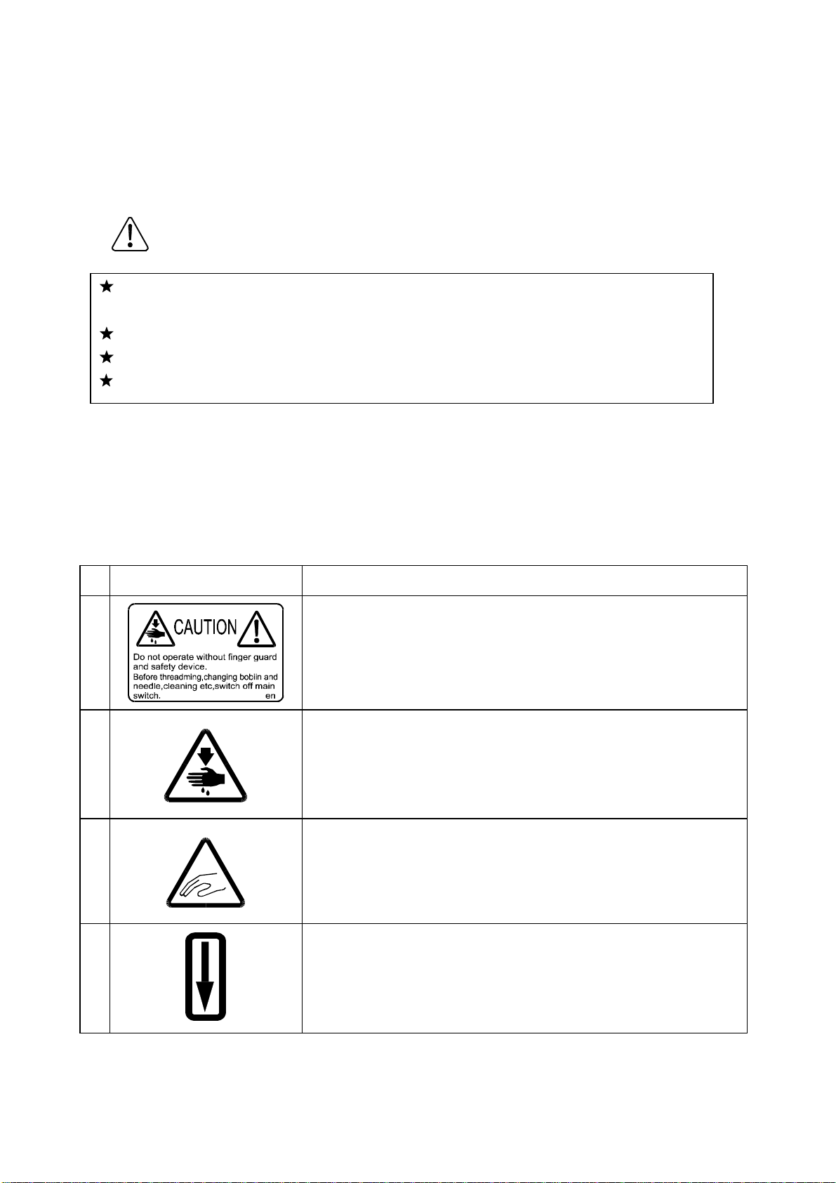
Explanations for the wa r ni ng signs
No Warning sign
1
Caution for sewing machine operation:
Warning to operate the sewing machine without safety
guards and to prohibit doing any operation except sewing
while the power is turned ON.
Meanings of warning sign
2
3
4
Caution for a wound on the fingers:
Warning to a possible danger to cause a wound on the
fingers under the specif ied oper at ion.
Caution for the fing er s to be caught in the machine:
Warning to a possible danger to be caught the fingers in the
machine under the specified operation.
Direction of pulley rotation:
Indicating the proper rotating direction of the sewing
machine pulley.
Page 3

ENVIRONMENT STANDARD
For avoiding the sewing machine from the troubles, please do not operate the sewing
machine under the following conditions.
Caution
(1)
(a) During operating : The atmosphere temperature should not exceeded more 35ºC
(b) During transportation : The atmosphere temperature should not exceeded more
(2)
(a) In the atmosphere filled with dust or cor r osive g as.
(b) In the atmosphere filled with f lam mable or explosive gas.
(3)
(a) In the place where the power fluctuation exceeds more or less 10 % of the fixed
(b) In the place where the power source can not supply enough voltage to keep the
(4)
Temperature and humidity
(95ºF) or less 5ºC(41ºF).
55ºC (131ºF) or less -10ºC (18ºF) .
The relative humidity in the atmosphere should not exceeded more 85% or less 45%.
Atmosphere for the machine oper at ion
Power source voltage
power voltage.
motor running.
Power source voltage
(a) In the place where the power fluctuation exceeds more or less 10 % of the fixed
power voltage.
(b) In the place where the power source can not supply enough voltage to keep the
motor running.
(5)
Noise
(a) In the place near a high frequency tr ansm it t er or a high frequency welder.
(b) In the place filled with strong electrom agnetic radiation or magnetic field.
Page 4

·
·
·
·
·
CONTENTS
1. STRUCTURE OF THE MACHINE ······································································
2. SPECIFICATION ··································································································
3. INSTALLATION ···································································································
1
2
3
3-1. Preparation of the table ··················································································
3-2. Preparation for the steel stand ········································································ 3
3-3. Installation of the motor ··················································································
3-4. Installation of the control box ·········································································· 3
3-5. Connection of the operation panel ·································································· 3
3-6. Installation of the power switch ······································································· 4
3-7. Connection of the foot switch ········································································· 4
3-8. Installation of the oil pan ················································································· 5
3-9. Installation of the sewing machine head ·························································
3-10. Putting across the V-belt ··············································································· 6
3-11. Connection of the electric cables ··································································
3-12. Installation of the belt cover ········································································· 8
3-13. Installation of the thread stand ······································································ 9
3-14. Functioning the work holder pedal ································································ 9
4. LUBRICATION ····································································································
3
3
5
7
10
5. PROPER OPERATION ······················································································
5-1. Loading the system software to the control box ············································· 11
5-2. Installation of the needle ················································································· 11
5-3 Threading the upper thread ············································································· 12
5-4. Winding the bobbin thread ············································································· 12
5-5. Setting the bobbin ··························································································· 14
5-6. Setting the bobbin case ·················································································· 14
6. PROPER SEWING ·······························································································
6-1. Operation of the halt switch ············································································
6-2. The sewing operation ····················································································· 16
6-3. Adjustment of the thread tension ···································································· 17
11
15
15
Page 5

·
·
·
·
·
·
·
·
·
7. ST ANDARD ADJUSTMENT ···············································································
7-1. Adjustment of the needle bar position ····························································· 19
7-2. Adjustment of the position between the needle and the shuttle hook ·············· 20
7-3. Adjustment of the clearance between the shuttle hook and the needle ··········
7-4. Adjustment of the clearance between the driver and the needle ····················· 21
7-5. Adjustment of the thread guide ······································································· 22
7-6. Adjustment of the presser foot ········································································ 22
7-6-1. Adjustment of the presser foot position ················································
7-6-2. Adjustment of the presser foot lift during the sewing ····························
7-6-3. Adjustment of the presser foot timing ··················································· 25
7-7. Adjustment of the wiper ·················································································· 26
7-8. Adjustment of the bobbin winder ····································································· 27
7-9. Adjustment of the work holder ········································································
7-10. Adjustment of the trimmer cam follower ························································ 28
7-11. Adjustment of the position for movable knife point ········································ 28
7-12. Adjustment of the fixed knife position ···························································
7-13. Adjustment of the thread take up spring stroke ············································
7-14. Adjustment of the thread take up spring tension ··········································· 29
7-15. Adjustment of the thread tail after the trimming ············································
7-16. Cancellation of the trimming function ···························································· 30
7-17. Adjustment of the upper thread tension ························································ 30
7-18. Adjustment of the synchronizer ····································································· 31
7-19. Adjustment of the mechanical home position ················································ 32
7-19-1. Shifting the mechanical home position X direction ······························ 32
7-19-2. Shifting the mechanical home position Y direction ······························ 33
7-20. Adjustment of the X-Y contact pressure ······················································· 34
19
21
22
25
27
29
29
30
7-21. Adjustment of the X-Y timing belt tension ····················································· 34
7-21-1. Adjustment of the X timing belt tension ··············································· 34
7-21-1. Adjustment of the Y timing belt tension ··············································· 35
7-22. Adjustment of the V belt tension ··································································· 35
8. MAINTENANCE ·································································································
8-1. Cleaning ·········································································································
8-2. Disposing of oil waste ····················································································· 36
9. BAD SEWING CONDITION & ITS CAUSE AND REMEDY ···························
APPENDIX ··················································································································
Ref.1. Table cut out drawin g ···················································································· 41
Ref.2. Table & stand assembly ················································································ 41
Ref.3. St and components drawin gs ········································································
36
36
37
40
42
Page 6
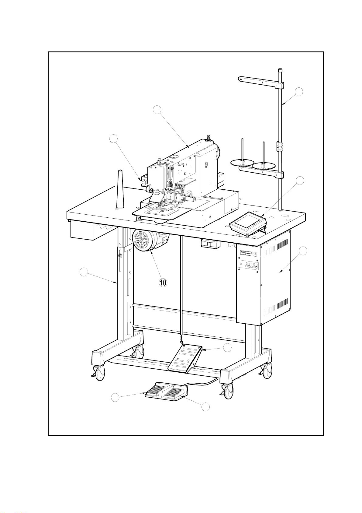
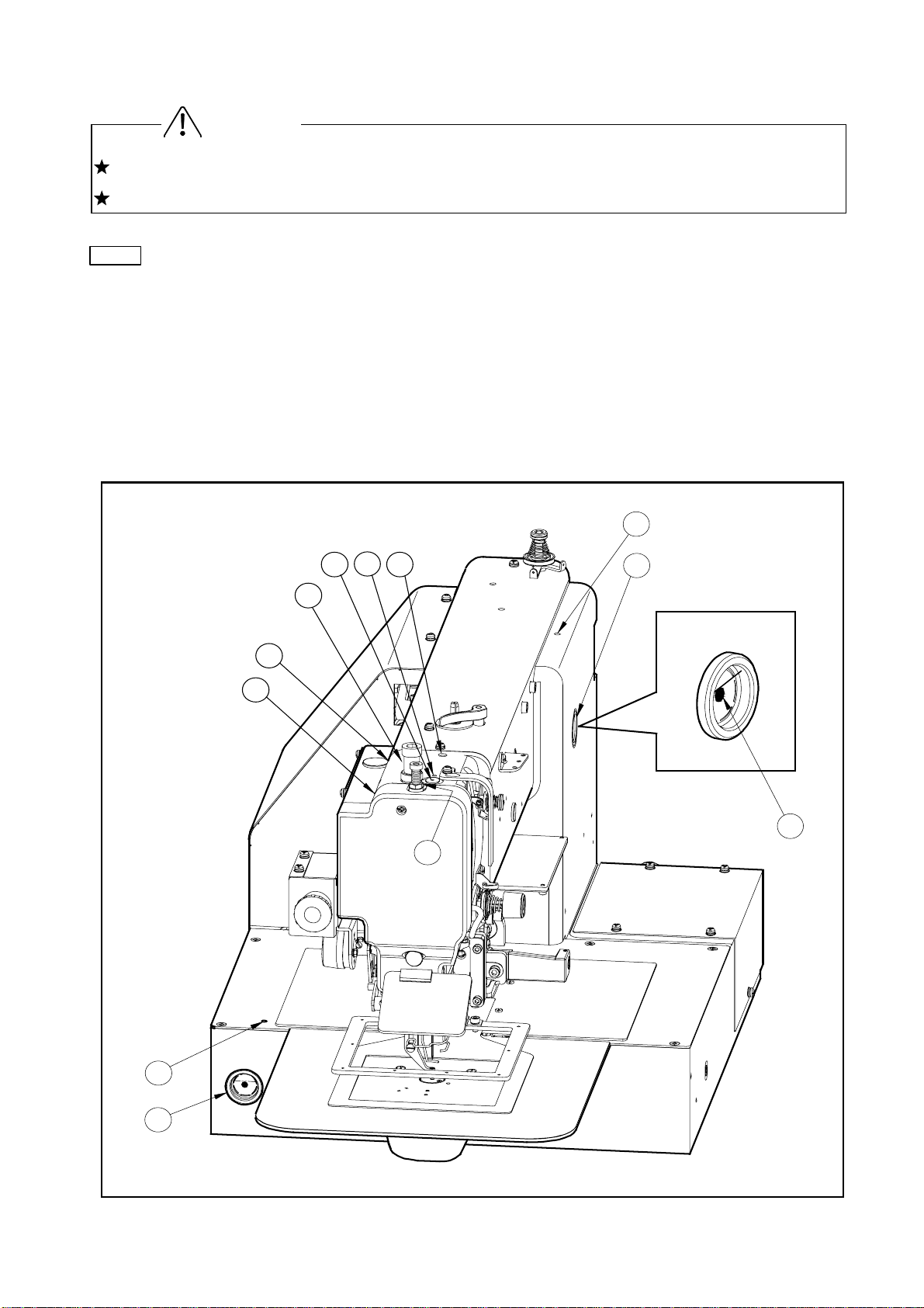
1. STRUCTURE OF THE SEWING MACHINE
PLK-E1010 electronic pattern sewing machine is constructed with the following main parts.
1
5
2
3
4
9
8
7
6
1
Sewing machine head 2Thread stand
6
Work holder foot switch 7 Start foot switch
*Limi-servo motor
3Operation Panel
8Work holder pedal 9Steel stand
1
4Control Unit
5Halt switch
Page 7

2. SPECIFICATION
(1) Specification of mechanism
Sewing area : X-Direction (left/ right) Y-Direction (fore/backward)
: 100mm 100mm
Maximum sewing speed : 2500 rpm
Sewing speed : 10 steps variable from 200 to 2500 rpm
Stitch length : 0.1 to 12.7 mm
(Adjustable from 0.1mm to 12.7mm by 0.1mm resolution)
Stitch type : Single needle lock stitch
Needle bar stroke : 41.2 mm
Thread take up lever stroke : 68 mm
Class of needle : DP X 17 # 16 (the standard specification)
Wiper system : Back to forward wiping system (the standard specification)
Left to right wiping system (t he optional specification)
*1
Presser foot lift
Presser foot stroke
Work holder lift
: 15 mm (18mm max.)
*2
: Variable from 4mm to 10mm ( 4m m is standard)
*2
: 25 mm
Hook : Large size shuttle hook
Bobbin case : With non racing spring
Bobbin : Large size aluminum bobbin
Thread trimmer system Horizontal engagement with fixed knife and movable knife
Lubrication system :
Manual oiling and replenishment with the oil braids from the oil
tanks
Lubrication oil : White machining oil
X-Y drive system : Stepping motor and timing belt drive
Intermittent or continuous feeding
Machine dimension : 1,200mm(W) x 565mm(L) x 1,220mm(H)
Weight : TOTAL 143Kg
Type of controller : PLK-E-CU-20
Steel stand : T-shape steel stand for the standing or the sitting operation
(2) Specification of main motor
Type of motor : XL- 554- 20
2
Page 8

Cautio
3. INSTALLATION
The machine should be installed by the specialists who have enough experience for the
sewing machine installations.
All the necessary electric wiring should be done by electric engineers who are qualified for the
electric wiring.
If any damage or fault is found on the machine at the installation, please do not operate until it
is repaired.
Please do not operate the sewing machine with excessive modifications from the standard
specification
3-1 Preparation of the table
If the table is not MITSUBISHI original, the thickness of the table is required to have 40mm
more.
And please refer to the cut out t able dr awing for your own preparation.
The cut out drawing is shown on the last page of this technical manual as APPENDIX drawing.
3-2 Preparation for the steel stand
If the steel stand is not MITSUBISHI original, please refer to the assembling drawing for your
own preparation.
The assembling drawing is shown on the last page of t his t echnical manual as Ref.1 to Ref.3.
If the steel stand is MITSUBISHI original, please assemble the steel stand with the assembling
instructions enclosed in the packing.
3-3 Installation of the motor
If the motor is purchased without assembling to the table, the motor has to be installed
underneath the table.
Please install the motor with the instructions explained in the paragraph [Installation of the
Motor] on the other [CONTROL UNI T] technical manual.
3-4 Installation of the control box
If the control box is purchased without assembling to the table, the control box has to be
installed underneath the table.
Please install the control box with the instruction in the paragraph [Installation of the control
n
box] on the other
CONTROL UNIT technical manual.
3-5 Connection of the operation panel
Please connect the operation panel with the instructions of Operation Panel manual enclosed in
the packing.
3
Page 9
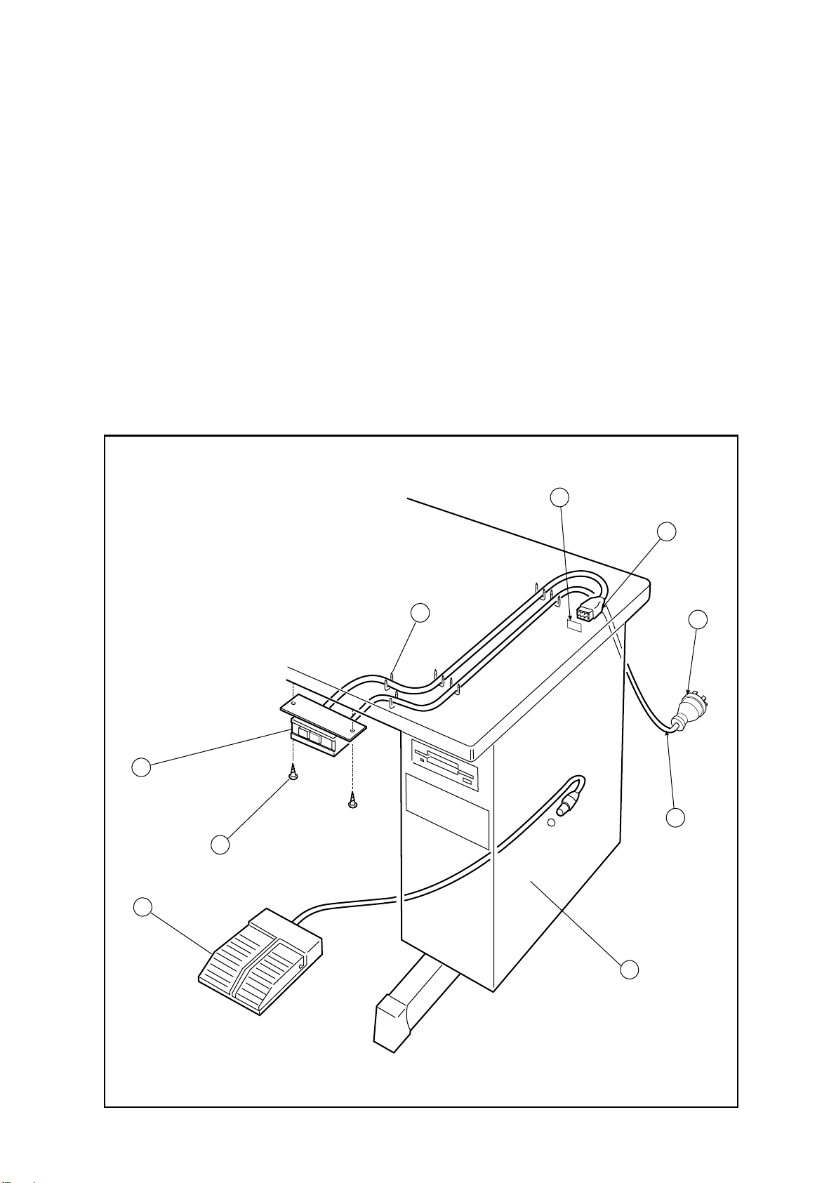
3-6 Installation of the power switch
If the power switch is purchased without assembling to the table, the power switch has to be
attached with the following procedure.
(1) Mount the power switch (NO.1) with the wood screw (NO.2) underneath the table as shown
on the figure.
(2) Fix the electric cords with the staples (NO.3) underneath the table.
(3) Hook up the connector (NO.4) of the power switch (NO.1) to the connector (NO.5) of the
control box (NO.9).
(4) Attach the power plug (NO.7) to another end of the power switch cord (NO.6).
3-7 Connection of the foot switch
Connect the foot switch (NO.8) t o t he cont rol box (NO.9)
The foot switch is enclosed in the accessory box.
5
4
3
1
2
7
6
8
4
9
Page 10
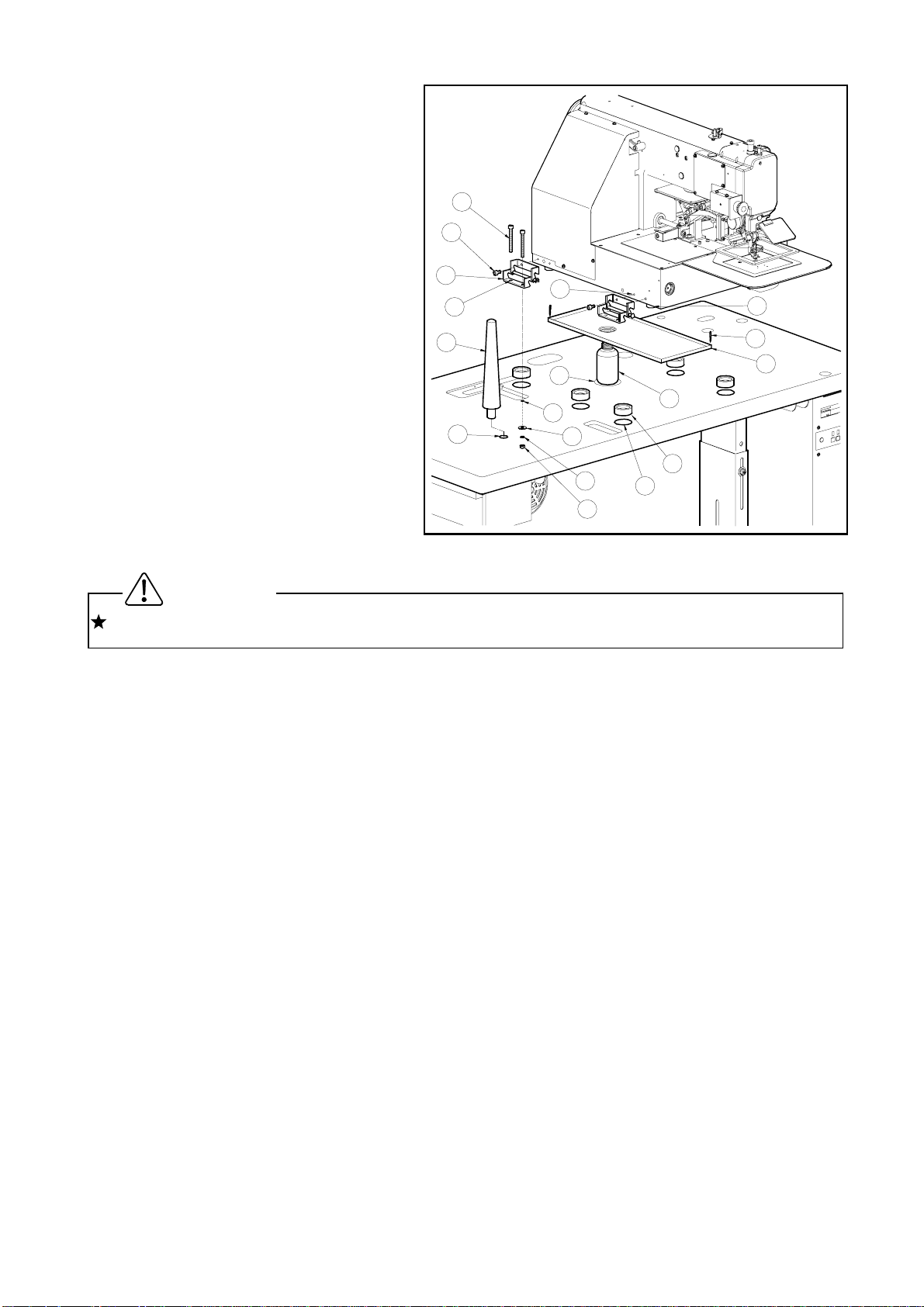
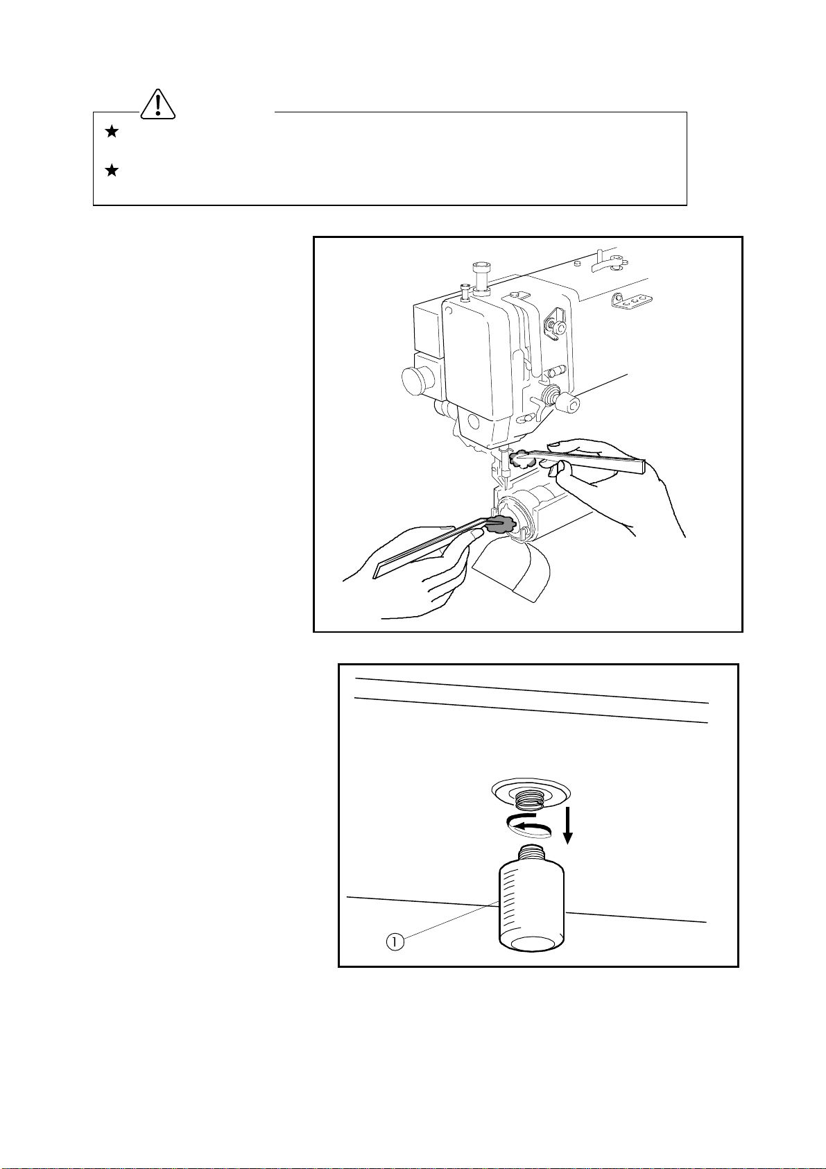
3-8 Installation of the oil pan
(1) Assemble the oil pan (NO.1) and
oil bottle (NO.2), which are
enclosed in the accessory box.
(2) I nsert the oil bottle (NO.2) into the
tabletop cut-out hole (NO.3), which
14
11
has much shorter distance from
the bottle center to the fr ont.
(3) Install the oil pan (NO.1) parallel
with the table front edge.
(4) Fix the oil pan (NO.1) at its four
corners on the table top with four
staples (NO.4) en-closed in the
accessory box.
18
9
13
19
12
10
8
4
3
2
15
6
16
17
7
1
3-9 Installation of the sewing machine head
For the safety, please make sure t o carry the sewing machine head by more than two people.
(1) Make sure to hold the machine table with the caster stopper.
(2) Fit t he rubber cushion pads (NO.6) into the each hole (NO.7) on the tabletop. The rubber
Caution
cushion pads (NO.6) are enclosed in the accessory box.
(3) Put the sewing machine head on the table top and set the each leg (NO.8) to the each
rubber cushion pad (NO.6)
(4) Att ach two hinges (NO.9) temporarily, make the setting screw (NO.11) fastening with the
thread holes (NO.10) light, on the left side surface of the machine bed with the hexagonal
socket head set screws (NO.11).
(5) At this time, take notice that the E-shaped snap ring on the front side hinge must be come
to the backside, and E-shaped snap ring on the backside hinge must be come to the front.
(6) These parts are all enclosed in the accessory box.
(7) Fit the screw holes (NO.13) of the hinges (NO.9) to the bolt setting holes (NO.12) on the
table top then, pass the bolt (NO.14) through these holes and fasten the bolt (NO.14) to fix
the hinges (NO.9) with the flat washers (NO.15), the spring washers (NO.16) and the nuts
(NO.17).
(8) Fasten firmly hexagonal socket head set screws (NO.11), which set the hinges (NO.9)
temporarily at above procedure (4) then, fix the hinges (NO.9) perfect ly.
(9) Insert the headrest (NO.18) into t he hole ( NO .19) on the tabletop.
5
Page 11
Cautio
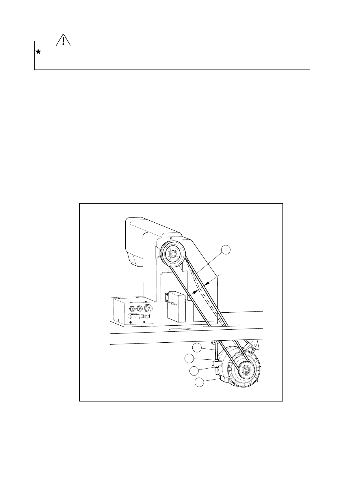
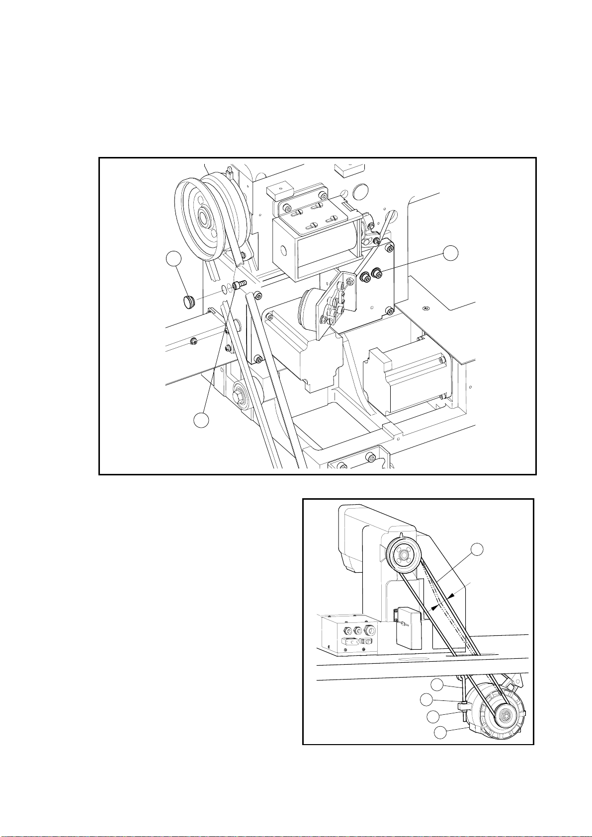
3-10 Putting across the V-belt
For the safety, when tilt or raise the sewing machine head, please make sure to hold the
sewing machine head with both hands by two people at least.
(1) Tilt the sewing machine head to the left, and hold it with the head r est.
(2) Put the V-belt (NO.4) across the sewing machine pulley and the motor pulley with passing it
through the slit on the tabletop.
(3) Raise the tilted sewing machine head to the original position.
(4) Push the center portion of V-belt by the f inger with the presser of about 1Kg.
If the V-belt tension is proper , it should be yielded about 10 mm.
If the V-belt tension is not pr oper, please adjust it as follows.
(5) Loosen two nut (No.2) on the motor .position adjust bolt (No.1).
(6) Fix the motor (No.5) position with putting the tension to the V belt by its weight and firstly,
tighten the upper nut (No.2) t hen secondly, t ighten the lower nut (No.2).
Please make sure to fasten t he nut s ( NO . 5) firmly after the adjust m ent .
(7) Put the motor pulley cover on the motor with the set screws.
n
10
4
mm
1
2
6
3
5
Page 12
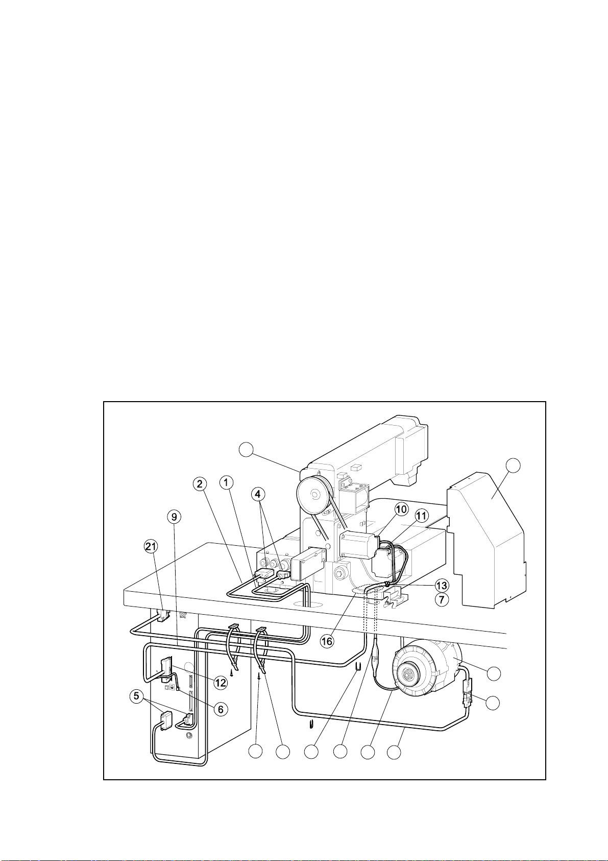
3-11 Connection of the electric cables
(1) Connect t he white color cable (NO.1) and the black color cable (NO.2) across the printed
circuit board unit connectors (NO.4) on the sewing machine head (NO.3) rear face and the
connectors (NO.5) on the control box. T hese cables ar e enclosed in t he accessor y box.
(2) Remove the stepping motor cover (NO.8) f r om sewing machine head ( NO . 3).
(3) Pass upward the cable (NO.9) which is attached the two connectors at the end, through the
cut-out hole (NO.16) on the table top then, connect it to the X-stepping motor connector
(No.11) and to the Y-stepping motor connector (No.10). At this time, fix this cable with the
nylon clip (NO.13) and setscrew (No.7) which are provided on the sewing machine head.
And also, connect the other end of the cable (NO.9) to the connector (NO.12) on the control
box. The cable (NO.9) is enclosed in the accessory box.
(4) Pass downward the another cable (NO.15) which is extended from the sewing machine
head through the cut-out hole (NO.16) on the table top then, connect it to the cable (NO.18)
extended from the motor (NO . 17)
(5) Connect the last cable (NO. 19) to the other extended cable (NO.20) from the motor then,
hook up the other end of the cable ( NO.19) to the connector (NO.21) on the control box.
(6) Attach the tow binder (NO.22) underneath the table with the wood screws (NO.23) then,
bundle and fix all the connected cables with the binders (NO.22) and the staples (NO.23).
The binders (NO.22), the wood screws (NO.23) and the stables (NO.24) are enclosed in
the accessory box.
3
8
17
20
23
15
2422
18
19
7
Page 13
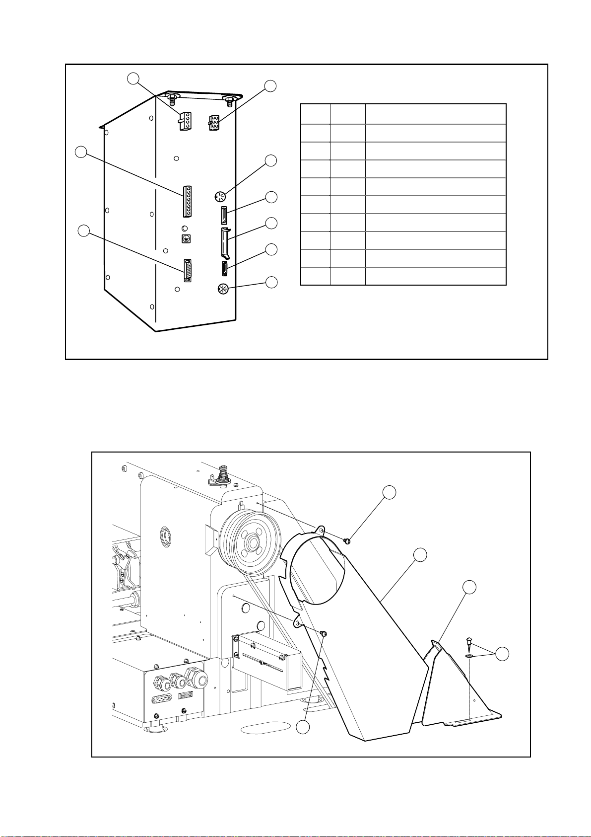
< Back side view of the Control box >
3
4
1
2
Fig Con Connect with
1 A Main motor cable
2 B Power supply cable
5
6
7
8
9
3 C Stepping motor cable
4 D Solenoid output cable
5 E RS-232C (optional use)
6 F O per at ion panel cable
7 G Extension I/O cable
8 H Input signal cable
9 I Foot switch cable
3-12 Installation of the belt cover
Put the large belt cover (NO.2) on t he sewing machine head with the set scr ews (NO. 1 & 4)
and small belt cover (NO.3) on the table top with the set screws (NO. 5)
All the necessary parts are enclosed in the accessory box.
4
2
3
5
1
8
Page 14
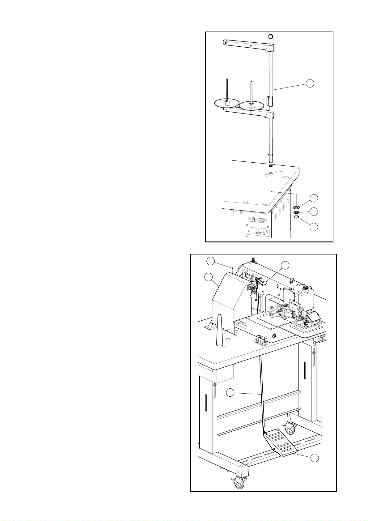
3-13 Installation of the thread stand
(1) Assemble the thread stand with the
instructions enclosed in the packing.
(2) Fit the thread stand (NO.1) in the thread
stand hole on the tabletop.
(3) Fix the thread stand (NO.1) firmly from the
rear side of the table with tightening the nut
(NO.4) and the washers (NO.2, 3).
1
2
3
4
3-14 Functioning the work holder pedal
(1) Connect the chain (NO.1) across the
lever (NO.2) located at the left side of the
sewing machine head and the work
holder pedal mounted on the steel stand
bottom beam. The chain (NO.1) is
enclosed in the accessory box.
(2) Put the stepping motor cover (NO.4) back
on the sewing machine head with the
screw (NO.5) after the chain (NO.1)
connection.
5
2
4
1
9
3
Page 15
Cautio
4. LUBRICATION
Please make sure to turn power switch OFF befor e oiling.
Please make sure to put some oil before starting the operation of the brand new machine or
NOTE Please use high quality white machining oil.
4-1 Filling the oil tank
Pour the oil through the oil hole (NO.1) to the oil tank (NO.2) on the machine arm. Move the
work holder by hand to the right end then, machine bed. Please fill with the oil over level mark
(NO.6) of the oil tank.
4-2 Oiling
Put some oil to red marked oil holes (NO . 7 ~ 13).
n
8
9
10
11
12
7
13
1
2
6
4
5
10
Page 16
5. PROPER OPERATION
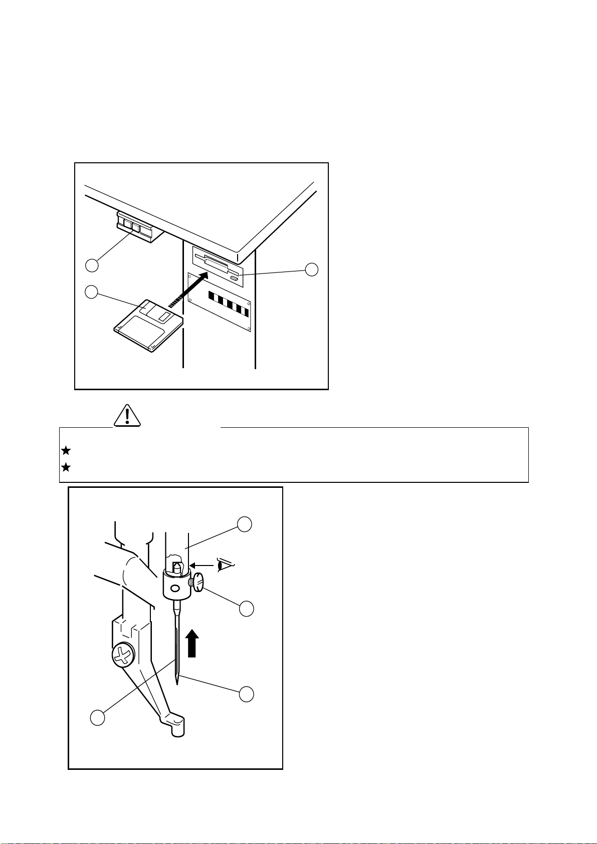
5-1 Loading the system software to the control box.
When the brand new machine is operated first time or when the control box is adjusted for the
repairing, the system software has to be loaded t o the control box.
For this loading, please take the following procedure.
(1) Insert the system floppy disc printed
[ F1 ] (NO.2) into the disc drive (NO.3)
of the control box.
O
F
F
O
N
(2) The system floppy discs are enclosed
in the accessory box.
1
(3) Turn the power switch (NO.1) ON.
3
(4) Load the system software with
2
5-2 Installation of the needle
Please make sure to turn the power switch OFF bef or e installing or replacing the needle.
Please pay attention for the fingers not to be wounded by the needlepoint.
Caution
(1) Loosen the needle set screw (NO.1) then,
insert the new needle (NO.2) until the
3
needle head is reached the end of the
following the instructions [Loading the
system software] on the technical
manual [
(5)
After loading the system software,
CONTROL UNIT].
keep the system floppy disks with in
care.
hole of the needle bar (NO.3).
(2) Fasten the setting screw (NO.1) with
facing the needle groove (NO.4) to the
1
front.
2
4
11
Page 17

5-3 Threading the upper thread
Please make sure to turn the power switch OFF before threading the upper thread.
Please thread the upper thread with referr ing to the below figures.
Caution
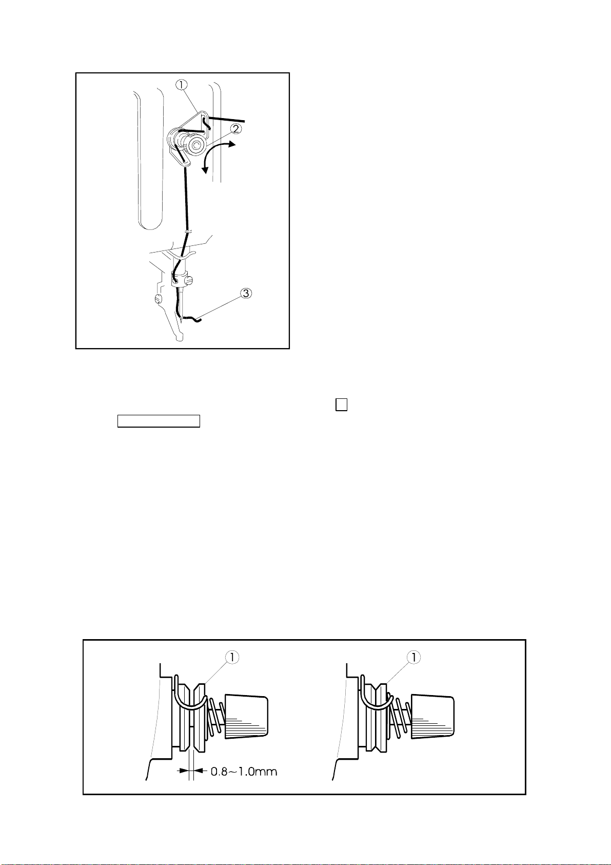
5-4 Winding the bobbin thread
Please make sure to pull the upper thread out of the needle before winding the bobbin
(1) Turn the power switch ON.
(2) Press the key on the operation panel
Caution
to enter the second operation window.
(3) Pass through the thread from the thread
stand (NO.3) as shown on the below figure
then, wind the thread to the empty bobbin
(NO.4) in the arrow mark “a” direction couple
times and insert the bobbin (NO.4) into the
bobbin winder (NO.5).
(4) Push the adjust lever (NO.6) in the arrow
mark “b” direction.
(5) Step on the black color foot switch (NO.7)
then work holder goes down.
12
Page 18

(6) Press the key, then work holder
moves to home position.
(7) Press key on the operation panel.
Then presser foot goes down automatically,
and wind mode window will be appeared.
(8) Step on the black color foot switch (NO.7)
again to make work holder down.
(9) Step on the gray color start foot switch
(NO.9). The thread is kept winding to the
bobbin (NO.5) while the gray color start
switch is stepping on.
(10) When the bobbin becomes full of the thread,
the adjust lever (NO.6) is returned to the
original position.
(11) Stop to step the gray foot switch and press
the key to exit winding mode, and
press the key, to back to the standard
operation windows will be appeared.
(12) To wind the bobbin thread during the sewing operation, carry out above (3) and (4)
procedure then, the bobbin winding is perform ed automatically.
(13) Regarding the adjustment for the bobbin thread winding volume, please refer to the
instructions in the paragraph 7-11 Adj ustment of the bobbin winder in the following page.
4
a
5
b
6
9
7
13
3
Page 19

5-5. Settling the bobbin
(1) Set t he bobbin ( NO .2) into the bobbin case (NO.1).
(2) Pull the bobbin thread (NO.3) into the slit (NO.4) and pass the thread through the thread
hole (NO.5).
(3) At this time, pull the bobbin thread (NO.3) then, check with the bobbin (NO.2) if it is rotated
to the arrow direction. If it is not, set the bobbin (NO.2) into the bobbin case (NO.1) over
again to get the proper r ot at ion.
5
3
4
2
1
5-6. Setting the bobbin case
(1) Set the needle bar to its highest position then, open the cylinder cover (NO . 1) .
(2) Open the bobbin case latch lever (NO.2) fully then, f it it securely in the inner hook (NO.3).
[NOTE] Please pull the bobbin thread about 25mm out of the thread hole (NO.4) of the
bobbin case.
3
2
1
14
Page 20

6. PROPER SEWING
6-1. Operation of the halt switch
If an incident such as a thread breakage, needle breakage and any other incidents are
happened during the sewing operation, please hit immediately the halt switch. The sewing
machine running is stopped instantly.
Before start the sewing operation, please make sure the location of the halt switch and
keep it in mind the function and how to use it.
(1) Press the HALT switch (NO.1), All operations will stop, and the sewing machine will stop
at the needle UP state without trimming the thread.
(2) Remove the cause of the abnormality.
(3) To continue sewing, turn the HALT switch to the rig ht .
The switch will be unlocked.
Next, when the start switch (NO.3) (gray foot switch) is pressed again, the operation will
resume from the halted posit ion.
Caution
(4) To cancel sewing, turn the HALT switch (NO.1) to the right, and unlock the switch.
Then, press the key on the operation panel (NO . 2) .
The work holder (NO.4) will return to the home position from th e stopped position and will
stop.
1
2
4
3
15
Page 21

Caution
Depending on the shape of the work
holder, the collision may be happened
with the work holder and the presser foot
while the work holder is on the way back
to the home position. For avoidance of
this accident, before starting the sewing
operation, program the work holder
returning home with the operation panel
of the control box to trace the sewing
pattern.
For this setting, refer to the [Wiper
Setting] in the [PROGRAM MODE] on
the operation panel.
6-2. The sewing operation
Caution
It is very dangerous to operate the sewing machine without the safety guards (Eye guard,
Belt cover, Link cover, Finger guar d et c.).
Please make sure to always operate the sewing machine with the safety guards.
Please do not put unnecessar y art icles except for the sewing operation on the tabletop.
Please keep t he hands and t he face away from the needle.
(1) Turn the power switch (NO.1) ON.
NOTE The collision may be happened with the work holder (No.2) and the presser foot
(No.3) depending on the work holder shape when the work holder is moved to
original position.
In this case, if home positioning method [HPF] is set to ON, home positioning
switch becom es inact ivate during the work holder goes up.
(2) Program or select the requir ed sewing pattern by selecting following icon.
Programming -------- >>
Selecting pattern ---- >>
The sewing pattern programming or selecting can be performed with the operation panel.
For the details, please refer to the instructions on the technical manual [Operation
Panel].
(3) Set the sewing speed by selecting or icon.
(4) Insert the sewing material under the work holder (NO.3) then, step on the black color foot
switch (NO.4). The work holder comes down to press the sewing material.
[NOTE] If the sewing material has to be reset, step the black color foot switch (NO.4)
again then; the work holder goes up t o r elease t he sewing material.
16
Page 22

(6) Step on the gray color start switch (NO.5). T he sewing machine starts the sewing.
(7) After finished the sewing, the work holder is lifted automatically then, the sewing material
is released.
3
5
1
4
6-3. Adjustment of t he t hread tension
The thread tension between the upper and bottom thread should be balanced in the best
condition.
When the upper thread tension is well balanced with the bobbin thread tension, both
threads are interlocked along the centerline of fabric layers as shown on the below
figures.
2
NOTE Nor m ally weaker bobbin thread tension brings better sewing q uality.
So it is prefer to set bobbin thr ead t ension first and then set upper thread t ension.
17
Page 23

○
○ ×
○○
× ×
××
×
××
Well balanced
tension
(1) Bobbin thread tension
Adjust the bobbin thread tension with the thread tension adjusting screw (NO.2) on the
bobbin case (NO.1). The thread tension becomes loose if turn the thread tension adjusting
screw (NO.2) to the counterclockwise, and the thread tension becomes tight if turn it to the
clockwise.
(2) Upper thread tension
Adjust the upper thread tension based on the bobbin thr ead tension.
For this adjustment, turn the thread tension adjusting nut (NO.3). The upper tread tension
becomes tight if turn the thread tension adjusting nut (NO.3) to the clockwise, and the
upper thread tension becomes loose if tur ns it t o the counterclockwise.
The upper thread is tight
or the bobbin thread is loose
The upper thread is loose
or the bobbin thread is tight
1
2
3
18
Page 24

7. STANDARD ADJUSTMENT
Please make sure to turn the power switch OFF befor e adjust the sewing machine.
If the adjust ment is required under t he power switch is ON, keep the start f oot switch
away from the foot.
Be careful not to be wounded by the needle or the inner hook point .
Please make sure to put the safety guards (Eye guard, Belt guard, Link cover and
finger guard etc. ) back on the original location after t he sewing machine adjustment.
7-1. Adjustment of t he needle bar position
(1)Turn the power switch OFF.
(2)Turn the sewing machine pulley by hand then, stop the needle bar (No.1) at the lowest
position.
(3)Remove the rubber plug (No.2) from the face plate then, loosen the needle bar holder
setscrew (No.3).
(4)Move the needle bar (No.1) to the position where the needle bar timing mark A is matched to
the needle bar bushing bottom line (No.4) t hen, tighten the needle bar holder setscrew (No.3).
[NOTE] If the needle class is DP x 5, match the needle bar timing mark B to the needle bar
Caution
bushing bottom line (No.4).
― 19 ―
Page 25

7-2. Adjustment of t he position between the needle and the shuttle hook
(1) Turn the power switch OFF.
(2) Turn the sewing machine pulley by hand then, move up the needle bar ( No. 1) from the lowest
position and stop it at the position (No.2) where the needle bar timing mark C is m atched to
the needle bar bushing bottom line.
[NOTE] If the needle class is DP x 5, match the needle bar timing mark D to the needle bar
bushing bottom line (No.2).
(3) Open the cylinder cover(No.2).
(4) Remove the bobbin case (No.3).
(5) Turn the hook retainer lever (No.5) then, remove the hook r etainer (No.6).
(6) Loosen the driver setscrew (No.9) then, move the driver (No.10) and adjust the shuttle hook
point (No.7) to be matched with the center line (No. 8) of the needle.
(7) After the adjustment, tighten the driver setscrew (No.9) and put the bobbin case (No.4), the
hook retainer (No.6)and the hook retainer lever (No.5) back to the original location then,
close the cylinder cover (No.3).
2
D
1
6
4
5
C
3
8
10
7
9
― 20 ―
Page 26

7-3. Adjustment of t he clear ance between the shuttle hook and the needle
(1) Please take the same procedur es as above paragraph 7-2. from (1) t o (5).
(2) Loosen the outer hook setscr ew (No.3) and turn the eccentric pin (No.4) so that the clearance
between the shuttle hook point and the needle becomes 0.05~0.1mm.
(3) After the adjustment, securely tighten the outer hook setscrew (No.3) and put the hook
retainer and the bobbin case back to the original location then, close the cylinder cover
(No.5).
1
2
0.05 ~ 0.1mm
5
7-4. Adjustment of t he clear ance between the driver and the needle
(1) Please take the same procedures as above paragraph 7-2. from (1) to (5).
(2) Please make sure the clearance between the shuttle hook point and the needle has been
adjusted 0.05~0.1mm at above procedure 7-3 Adjustment of the clearance between the
shuttle hook and the needle.
(3) Loosen the driver setscrew (No.1) and turn the eccentric pin (No.2) so that the clearance
3
4
between the driver (No.3) and the needle (No.4) can become 0.
(4) After the adjustment, securely tighten the driver setscrew (No.1) and put the hook retainer
and the bobbin case back to the original location t hen, close the cylinder cover(No.5).
― 21 ―
Page 27

7-5. Adjustment of t he thread guide
(1)
Remove the E-shaped snap ring (No.3) which is engaging the movable knife (No.2) and the
link (No.1) then, loosen the setscrews (No.4) and remove the sliding plate (S)(No.5).
(2) Loosen the setscrews (No.10) and move the thread guide (No. 6) to the position where the
needle center line (No.8) divides the needle groove (No.7) evenly and the rear side line
(No.9) of the needle is aligned with the shoulder ( No.9) of the thread guide (No.6) . At this
time, make sure that there is some clearance between the hook retainer and the thread
guide (No.6) at least the upper thread can be passed smoothly through it (standard
clearance is 0.8mm).If this clearance is too wide, it causes the trimming failur e and if this
clearance is too narrow, it causes the sewing condition disturbance, the trimmed upper
thread tail uneven and the locking up the hook with the upper thread.
(3) After the adjustment, engage the link (No.1) of the trimmer mechanism with the movable
knife (No.2) with the E shaped snap ring (No.3) and put the sliding plate (S)(No.5) back on
the original location then, tighten the setscrews (No.4).At this time, set the sliding
plate(S)(No.5) so that the needle (No.11) can come down to the center (No.12) of the
needle hole of the needle plate.
4
6 8
5
1
10
7
0.8mm
1
3
7-6. Adjustment of t he pr esser foot
[NOTE] The presser foot is a very important part to form the fine stitches.
It moves simultaneously with the needle and stabilize the needle penetrating area of t he
sewing material with pressing down it, when the needle sticks into or pulls out the
sewing material and prevent the skip stitch or the over penet ration happening. Please
adjust the presser foot pr oper ly to t he sewing mat er ials with the following instructions.
7-6-1. Adjustment of t he presser foot position
11
13
9
12
[NOTE] Please always adjust the presser foot position when the thick ness of the sewing
material is changed.
― 22 ―
Page 28

(1) Turn the power switch OFF.
(2) Remove the face plate (No.1) and the link cover ( No. 2) .
(3) Turn the sewing machine pulley by hand and stop the needle bar (No.3) at the lowest
position. At this time, make sure the setscrew (No.5) of the eccentric cam (No.4) is
positioned right beside the center line of the upper shaft. This is the standard position of
the eccentric cam (No.4).If the eccentric cam (No.4) is off from this posit ion, set it back to
the standard position with the instructions on the paragraph [7-6-3. Adjustment of the
presser foot timing] in t he following page.
(4) Turn the sewing machine pulley by hand and stop the needle at t he highest position ( this
is also the thread take up lever's highest position).At this time, loosen the set screw (No.9)
of the upper feed lock cr ank shaf t(No. 8) and adjust the cent er line of the bell crank (No.6)
to be parallel with the presser foot bar (No. 7) .
(5) Insert the sewing material (No.10) under the work holder (No.11) and turn the sewing
machine pulley by hand then, stop the presser foot (No.12) at the lowest position.
(6) Loosen the presser f oot bar setscrew (No.14) and move the presser foot bar (No.7) then,
adjust the presser foot ( No.12) position to be become the clearance between the bott om
surface of the presser f oot (No.12) and the surface of the sewing mat erial 0~0.5mm. At
the same time, rotate the presser f oot bar (No.7) for the needle (No.15) to come down to
the center of the needle hole of the presser foot (No.12).
(7) After the adjustment, put the face plate (No.1) and the link cover (No.2) back on the
original location.
[NOTE] The lower position of t he pr esser foot, the more ef fective for the skip stit ches.
However, if the presser foot becomes to press the sewing material, the movement of
the presser foot mechanism g enerates a slight noise. And also, the presser f oot stays
longer to hold the sewing material, so the upper thr ead tension becomes loose or the
sewing pattern forming gets out of shape because the presser foot catches the
surface of the sewing material. For avoiding these troubles, please lower the presser
foot as small as possible.
2
8
6
3
11
― 23 ―
Page 29

[NOTE] If the thick ness of the sewing material chang es very often, it is recommended to tak e
the easy way for the adjustment of the presser foot position with the method that
change only the fixed position of the presser foot after fixed the presser foot bar at
higher position.
For this adjustment, loosen the setscrew (NO.16) then, move the presser foot
(NO.12) up and down.
7-6-2. Adjustment of t he presser foot lift during the sewing
[NOTE] The presser foot lift during the sewing can be adjust ed 0 and 2 ~10mm.
(1) The presser foot lift during the sewing becomes 4~10mm at the condition which the
connection of the link (No.2) and the lever (No.3) with the shoulder screw(No.1) is as
shown on the figure and it becomes 2 to 4 mm if t he connection is m ade with A hole, and it
becomes 0 mm if the connection is made with B hole..
(2) The stepping lift is adjusted 4m m when the sewing machine is shipped from the factory.
(3) For the adjustm ent at the each range of the presser foot lift, rem ove the link cover (No.4)
then, loosen and move the adjust bolt(No.5).
(4) If the link (No.2) connection is changed to A or B hole, the presser foot position is also
changed. So reset the presser f oot position with adjusting the position of the presser foot
bar or the presser foot it self with loosing their setscrews (No.6) or (No.7).
(5) Reg arding the running noise and the vibration, the higher lift effects worse. So adj ust the
presser foot lift dur ing the sewing as small as possible.
(6) After the adjustment, put the link cover (No.4) and the face plate (No.8) back on the
original location.
4
B
A
3
2
8
1
6
7
― 24 ―
5
Page 30

7-6-3. Adjustment of t he pr esser foot timing
[NOTE] The presser foot up and down movement during the sewing synchronizes with the
needle up and down movement.
With changing this synchronized timing to the sewing materials, the skip stitches can
be prevented or the seam tightness can be improved.
For example, the delay of the presser foot timing against the needle movement
prevents the skip stitches especially to the thin materials, and the advance of the
presser foot timing can impr ove the seam t ightness especially to the thick materials.
(1) Remove the link cover(No.1).
(2) Loosen the setscrew "C" of the eccentric cam (No.2).
(3) Turn the sewing machine pulley by hand and stop the needle bar (No.3) at the lowest
position. At this stage, the setscrew "A" of the eccentric cam (No.2) is positioned right
beside the center line of the upper shaft. This is the standard position for the eccentric
cam (No.2).
(4) Loosen the setscrew "A" of the eccentric cam (No.2).
(5) Hold the eccentric cam (No.2) and turn the sewing machine pulley slowly by hand.
If turn the sewing machine pulley to the arrow direction " D", t he presser f oot t iming ag ainst
the needle movement is delayed, and if turn the pulley to the opposite direction, the timing
of the presser foot is advanced.
(6) After the adjustment, tighten the setscrew "A" and "C" in turn with slightly pushing the
eccentric cam (No.2) to the arrow direction "E".
(7) Put the link cover (No.1) back on the original location.
1
3
2
― 25 ―
Page 31

7-7. Adjustment of t he wiper
(1) Loosen the wiper setscrew (No.3) and adjust the wiper (No.1) to be positioned where the
wiper (No.1) passes under the needle point (No.2) with about 2 mm clearances right after
the sewing machine is stopped running at the needle upper position (the thread take up
lever's highest position).
[NOTE] When the presser f oot position or t he presser f oot lif t is changed, the wiper (No.1)
may collide with the presser foot (No.4).
In that case, please do not use the wiper (No.1).
(2) If do not use the wiper (No.1), cancel the wiper funct ion with operation panel as follows.
>> Press button at the normal mode condition, t hen MENU MODE is appeared.
>> Press button. Then below screen will be appeared.
>> Press [Wiper ] but ton.
>> And then press [W I P] and select
[OFF] button.
― 26 ―
Page 32

7-8. Adjustment of t he bobbin winder
(1) Adjustment of the winding volume
Loosen the setscrew (No.2) of the adjusting lever (No.1) and adjust the position of the
adjusting lever (No.1). If move the adjusting lever (No.1) to the arrow direction "a", the
winding volume is reduced, and if move the adjusting lever (No.1) to the arrow direction "b" ,
the winding volume is increased. The winding volume is adjusted 80 % of the full volume
when the sewing machine is shipped from the factory.
(2) Adjustment of the proper posit ion of the bobbin winder
Firstly, loosen the setscrews (No.3) and (No.4) of the bobbin winder and put the empty
bobbin (No.5) on the rotating shaft (No.6) then, push the adjusting lever (No.1) to the
arrow direction "a". Secondary, move the whole bobbin winder to the arrow direction "c" and
stop it at the position where the empty bobbin is rotated t hen, tighten the setscrews ( No.3)
and (No.4) of the bobbin winder. This is the pr oper posit ion of the bobbin winder.
a
b
1
5
3
6
c
4
2
7-9. Adjustment of t he work holder
If the sewing material is thick and t he work holder does not pr ess it strong enough, adjust the
work holder presser as follow.
(1) Insert the sewing material (NO.1) under the work holder ( NO . 2).
(2) Turn the power switch ON and lower the work holder (NO.2) with the work holder foot switch
(black color foot switch).
(3) Loosen the 2 of the setscrews (NO.3) and move adjusting plate (NO.4) until it touches with
the link (NO.5) then, tighten the 2 of the setscrews (NO.3).
2
5
4
1
3
― 27 ―
Page 33

7-10. Adjustment of t he trimmer cam follower
(1) Turn the power switch OFF and remove the top cover.
(2) Under the sewing machine regular stop condition (the needle stop posit ion is upper and the
take up lever stop position is highest), loosen the setscrew (No.5) of the cam f ollower lever
(No.4) and adjust the cam follower (No.2) to be positioned to contact with the shoulder
portion (No.3) of the trimmer cam (No.1) with having about 1mm clearance between the
cam follower (No.2) and the trimmer cam (No.1). After t his adjustment, tighten the set screw
(No.5) of the cam follower lever (No.4).
(3) Push the cam follower lever (No.4) by hand to the
the cam follower (No.2) is engaged into the cam groove (No.3) smoothly.
(4) If the cam follower (No.2) is not engaged smoothly, under confirming with the condition
which the cam follower (No.2) contacts with the shoulder portion (No.3) of the trimmer cam
(No.1), loosen the nut (No.7) and tig hten the stopper screw (No.8) until it touches with the
stopper (NO.9) of the cam follower lever (No.4) then, loosen the st opper screw (No.8) back
about 1/3 turn and fix the nut (No.7) firmly.
arrow direction and make sure that
7-11. Adjustment of the position for the movable knife point
(1) Tilt the sewing machine head to the left to be able to see the bottom component parts.
(2) Open the cylinder cover
(3) Check with the point (No.1) of the movable knife whether it is located at t he position apart
0.5mm from the front face of the hook retainer (No.2).
(4) For the adjustment of the movable knife point (No.1), loosen the adjusting screw (NO.3)
and move the rod end (No.4) right and left then, adjust the position of the movable knife
point.
(5) After the adjustment , tighten the adjusting screw nut (No.3) secur ely.
3
2
1
0.5mm
4
7-12. Adjustment of the fixed knife position
― 28 ―
Page 34

(1) Open the cylinder cover (No.1).
(2) Remove the E-shaped snap ring (No.4), which engages the movable knife (No.2) and t he
link (No.3).
(3) Loosen the setscrews (No.5) then, remove the sliding plate (NO. 6) .
(4) Turn the sliding plate (No.6) upside down and loosen two setscrews (No.9) then, adj ust the
fixed knife (No.10) position t o be positioned f or the blade edg e (No. 7) t o have the clearance
0.5mm from the edge of the needle plate (No.8).
(5) After the adjustment, t ighten the setscrews (No.9) securely.
(6) Put all the parts for this adjustment back to the original locations.
5
6
2
7
9
1
3
8
4
7-13. Adjustment of t he t hr ead take up spring swing stroke
Loosen the setscrew (No.2) and turn the whole thread tension regulator ( No.3) then, adjust t he
thread take up spring swing strok e to be become 9 to 10mm.
After the adjustment , tighten the setscrew (No.2) securely.
0.5mm
7-14. Adjustment of t he t hr ead take up spring tension
Insert the screw driver (No.5) into the slit (No.4) of the thread tension regulator (No.3) and
adjust the thread take up spring (No.1) tension. If turn the screw driver to the clockwise, the
thread take up spring tension becomes tight, and if turn the screw driver to the counter
clockwise, the thread take up spring t ension becom es loose.
― 29 ―
Page 35
7-15. Adjustment of the thread tail after the t rimming
Adjust the thread tail (No.3) from the
needle after the trimm ing with turning the
nut (No.2) of the pre-t ension ( No. 1) .
If turn the nut (No.2) to the clockwise, t he
thread tail becomes shorter and if turn the
nut (No.2) to the counter-clockwise, the
tread tail becomes longer.
7-16 Cancellation of the trimm ing function
If the automatic trimming is not required during the sewing operation, cancel the trimming
function with the setting panel of the control box. For t he detail of this instr uctions, please refer
to the paragraph [4.Program 4 mode display] on
manual
7-17. Adjustment of t he upper thread tension release
[NOTE]
CONTROL UNIT
(a) The upper thread tension release works when the upper thread is trimmed
automatically or the presser foot is lifted during the work holder feeding.
(b) If the upper thread tension release does not work properly when the upper
thread is trimmed automatically, the thread tail from the needle becomes
shorter then, it induces the skip st itch happening or pulling the thread tail out
of the needle at the start of the sewing.
(c) During the sewing operation, the discs (No.1) of the thread tension regulator
is closed while the presser foot is moving up and down.
If the discs (No.1) of the thread tension regulator is not closed, the upper thread
tension becomes loose and the proper stitch condition can not be obt ained.
(d) When the upper thread tension release is activated, the discs (No.1) the
upper thread tension regulator opens 0.8~1.0mm.This is the norm al condition
of the discs (No.1) opening. For this adjust m ent, take the following procedure.
.
9
Basic mode operation of the technical
(1) Remove the top motor cover.
― 30 ―
Page 36

A
(2) Fully turn t he crank (No.3) of the rotary solenoid (No.2) in the arrow direction. At this time,
adjust the upper thread tension release for the discs to be opened 0. 8 t o 1. 0mm.
A
(3) For this adjustment, loosen the nut
becomes wider and if loosen the nut
(4) If the normal opening of the discs can not be obtained with the nut adj ustment, loosen the
wire fix screws (No.5) and adjust the tension of the wire (No.6).
(5) The wire (No.6) may be got longer over a long period machine oper ation. At t hat t ime, adjust
the upper thread tension release again.
then, if tighten the nut B , the discs opening
B
, it becomes narrower.
1
0.8~1.0mm
3
5
6
2
A
B
7-18. Adjustment of t he synchronizer
A
[NOTE]
(a) W hen the sewing is finished, the arm timing mark
B
mark
are matched with each other then, the sewing machine is stopped
and the pulley timing
the running. This is the norm al condit ion.
A
(b) If theses timing mark
and B get out of the matching more than 3mm,
adjust the timing mark m atching.
Hold the sewing machine pulley (No.1) by hand and insert the angle adjuster (No.2) into the
C
hole
the pulley timing mark
mark
then, turn the angle adjust er (No.2).I f turn t he angle adjuster ( No.2) to the clock wise,
B
goes up and if turn it to the counter clockwise, the pulley timing
B
comes down. The angle adjuster (No.2) is enclosed in t he accessor y box.
B
― 31 ―
1
2
C
Page 37

7-19. Adjustment of the mechanical home position
[NOTE] The mechanical home position is fixed at the cent er of the sewing area when the
sewing machine is shipped from the fact ory. However, it can be moved within the
area covered with diagonal lines.
[
Rear side
[
Front side
(1) Turn the power switch ON and cancel the
sewing area limit with the operation panel.
For this cancellation, press key at
the normal mode condition, then MENU
MODE is appeared. Press
]
2
]
50
10
100
1
50
100
(1) Original home position
(2) Adj usta ble
key. And press [Area limit] butt on.
Please select [Area limit control (ALC) ] .
If you select ALC=ON, area limit control is
canceled.
[NOTE] If do not cancel t he sewing area
limit, shifting the mechanical
home position make the
effective sewing area narrower
than the original.
(2) After the cancellation of the sewing area
limit, once, turn the power switch OFF.
7-19-1. Shifting the mechanical home
position to the X direction
(1) Remove the X-Y cover (right), (left) and X cover.
(2) Loosen the detector plate fix screws (2 pieces) (No.1). If move the detector plate
(No.2) to the right, the mechanical home position is shifted to the left and if it is
moved to the left, the mechanical home position is shifted to the right.
― 32 ―
Page 38

(3) After the mechanical home position setting, tighten the detector plate fix screws
(No.1) securely.
(4) If the shift amount of home position by using this method enough. Please adjust
by following procedure.
(5) Remove the detector adaptor fix screws (No.3).
(6) Replace the detector adaptor (No.4) to other position. In this case if move the
detector adaptor (No.4) to the right, the mechanical home position is moved to
the right and if it is moved to the left, the mechanical home position is moved to
the left.
(7) After setting, tighten the detector adaptor fix screws (No.3) securely.
[NOTE] When the original mechanical home position is shifted. Please check the
clearance between the X detector plate and the X det ect or .
This clearance should be set within the range of 1.0 ~ 1.5 mm.
7-19-2. Shifting t he m echanical hom e position to the Y direction
(1) Loosen the Y-detector setscrew (No.1).
(2) If move the Y-detector (No.2) to the front , the mechanical home position is shifted t o the
backward. If it is moved to the backward , t he mechanical home position is shifted to the
front.
(3) After the mechanical home position setting, tighten the screw (No.1) securely.
1
2
4
3
2
1
7-20 Adjustment of the X -Y contact pressure
― 33 ―
Page 39

[NOTE]
When take the X-Y table apart or the X-Y table became weak in the joints,
adjust the X-Y table contact pr essure. The adjustment should be made t he X-Y
table movement as smooth as possible without having play. If the X-Y table
contact pressure is too tight, the over pressure induces the out of control on t he
X-Y table movement.
(1) Remove the right and left X-Y covers and the rig ht X cover plate.
(2) Loosen the setscrew (2 pieces) (No.2) so that the X fixed race (No.1) can be m oved slig ht ly.
(3) If tighten the both right and left contact presser adjusting screws (No.3), the X table contact
pressure is increased.
(4) Loosen the setscrews (2 pieces) (No.5) so that the Y fixed race (No.4) can be moved slig ht ly.
(5) If tighten the contact pressure adjusting screws (No.6), the Y table contact pressure is
increased.
(6) After adjustment, tighten the setscrews (No.2) and (No.5) securely.
7-21 Adjustment of the X-Y timing belt tension
[NOTE]
The proper condition of the X -Y timing belt tension is standing that they will not
be got any yield even it is slightly pushed by hand.
7-21-1 Adjustment of t he X timing belt tension
(1) Remove the right X cover and the right X cover plate.
(2) Loosen the nut (No.8) and the setscrew (No.9) of the br acket (No.7).
(3) If the tighten the tension adjust screw (No.10), the X timing belt (No.11) tension will be
increased.
(4) After adjustment, tighten the nut (No.8) and the setscrew (No.9).
4
5
6
7
3
2
1
8
9
7-21-2. Adjustment of the Y timing belt tension
― 34 ―
11
10
Page 40
(1) Remove stepping motor cover and V belt cover.
(2) Loosen the bracket setscrews (No.1).
(3) Remove the rubber plug (No.3) and tighten the tension adj ust screw (No.2). The Y timing
belt tension will be increased.
(4) After adjustment, tighten the bracket set screws (No.1) securely and put the rubber plug
(No.3), the stepping mot or cover and t he V belt cover to the original position.
3
2
7-22. Adjustment of t he V belt tension
[NOTE]
After operated the sewing machine
for a long period, the V belt tension
becomes loose. Adjust the V belt
tension periodically. The proper V
belt tension is standing that it is bent
about 10 mm with the hand pressure
of 1.0Kg as it shown on the fig ur e.
1
10
4
mm
(1) Turn the power switch OFF.
(2) Remove the V belt covers.
(3) Loosen two nut (No.2) on the motor
position adjust bolt (No.1)
(4) Fix the motor (No.5) position with putting
the tension to the V belt by its weight and
firstly, tighten the upper nut (No.2) then
secondly, tighten the lower nut (No.2).
― 35 ―
1
2
3
5
Page 41
8. MAINTENANCE
Please make sure to turn the power switch always OFF when clean up the sewing
machine.
Before or after the sewing operation, clean up t he sewing machine and check the
oil level in the oil tank.
8-1. Cleaning
(1) Turn the power switch
OFF.
(2) Remove the dust and the
thread waste sticking
around the threading
parts or the shuttle hook
area.
(3) Check the oil level in the
oil tank. If t he oil is under
the red mark level supply
the oil to be over the red
mark level.
Caution
8-2. Disposing of oil waste
(1)If the waste oil is full f illed in
the oil bottle (No.1), remove
the oil bottle (No.1) then,
dispose of the waste oil.
(2)For cleaning the oil pan,
remove the screw(No.2) and
take off the oil bottle
adapter(No.3).
Next remove the screw
(No.4) and pull out the oil
pan(No.5).
― 36 ―
Page 42

9. BAD SEWING CONDITION & ITS CAUSE AND REMEDY
[NOTE]
Bad condition Cause Remedy
Upper thread
breakage
often happens
Upper thread
is pulled out
from needle
Skip stitch
happens at
start sewing
Please fix the troubles during the sewing machine operation with referring to the
following instructions.
Beside, if the trouble conditions are not coming under these classification, please
contact the sewing machine dealers nearby.
Poor thread quality Use better quality thread ----
Tight upper thread tension Adjust thread tension 6-3
Adjust thread take up spring
properly
Change needle to suitable size ----
Change them new ones or grind
them with buffing wheel or grind
stone
Change it new one or grind it with
buffing wheel
Move presser foot position 7-6-1(6)
Adjust the timing 7-2
Slow down sewing speed 6-2(4)
Use silicon oil ----
Use needle cooler ----
Adjust thread tension release 7-17
Adjust thread take up spring’s
swing stroke
Adjust fixed knife and needle plate
position
Change needle to suitable size ----
Adjust thread guide position
properly
Adjust the position properly 7-2
Adjust trimmer cam position 7-10
Adjust movable knife position 7-11
Adjust synchronizer position 7-18
Use non racing spring with bobbin ----
Loosen bobbin thread tension
spring
Decrease pre-tension 7-16
Adjust trimmer cam position 7-10
Adjust synchronizer position 7-18
Make thread take up swing stroke
smaller
Advance thread tension release
timing
Adjust thread guide position
properly
1.
2.
3.
Strong thread take up spr ing
Upper thread is thicker than
needle size
Damages on shuttle hook or
driver
Damages inside presser foot
needle hole
Needle touches with presser
foot needle hole
Needle and shuttle hook are
not in proper timing
Thread melts with needle heat
Thread tension discs are not
opened at trimming
Thread take up spring swings
too much
Upper thread is broken befor e
regular trimming
Needle size is bigger than
thread size
Pre-tension is too tight Adjust pre-tension 7-16
Thread guide is in wrong
position
Needle and shuttle hook are in
bad timing
Trimmer timing is not correct
Too short bobbin thread by
bobbin spinning at trimming
Bobbin thread tension is too
tight
Thread tail from needle is very
short after trim m ing
Ref. page
& Item
7-14
----
----
7-14
7-12
7-5
6-3(1)
7-13
Control
unit
7-5
― 37 ―
Page 43

Bad condition Cause Remedy
Pre-tension is too loose Make pre-tension tighter 7-14
4.
Thread tail from
needle is too
long after
trimming
5.
Trimming is
not functioned
6.
Skip stitching
often happens
7.
Stitch forming
is loose
8.
Sewing
machine does
not work even
start switch is
turned ON
9.
Sewing
machine runs
idle at high
speed when
power switch
is turned ON
Trimmer timing is delayed
Upper thread tension release
timing is too fast
Tread guide is in wrong position
Trimmer function is canceled Resume trimmer function
Fixed knife is dull Change it new knife 7-11
Movable Knife is in wrong
position
Skip stitching happens at
trimming
Trimmer timing is wrong
Needle and shuttle hook
clearance is too big
Needle and shuttle hook timing
is not correct
Needle is bent Change it new needle ----
Needle is bent by driver
Needle is in wrong position Amend needle position 7-2
Presser foot position is not
correct
Upper thread tension is not
tight enough
Thread tension regulator’s
discs are opened during sewing
Presser foot position is not
correct
Driver and shuttle hook
clearance is very small
Presser foot up and down
timing is not proper
Cables wiring is disconnected Connect all cables precisely 3
System software is not loaded
Emergency stop switch is kept
ON
Start switch is out of order Change it new start switch ----
Synchronizer cable is
disconnected
Synchronizer is out of order
Adjust trimmer cam position 7- 10
Adjust synchronizer position 7-18
Delay tension release timing
Adjust thread guide position
properly
Adjust movable knife position
properly
Fix skip stitching 7-6
Adjust trimmer cam position 7- 10
Adjust synchronizer position 7-18
Adjust needle and shuttle hook
timing properly
Adjust needle and shuttle hook
timing properly
Adjust needle and diver clearance
properly
Adjust presser foot position
properly
Increase upper thread tension 6-3(2)
Adjust tension regulator posit ion
properly
Adjust upper tension release
position properly
Adjust presser foot position
properly
Change shuttle hook ----
Adjust presser foot timing properly 7- 6- 3
Load system software to control
box
Release emergency stop switch
lock
Connect synchronizer cable
precisely
Change it new synchronizer
Ref. page
& Item
Control
unit
7-5
Control
unit
7-11
7-2
7-2
7-4
7-6
7-17
7-17
7-6-1
5-1
6-1(3)
Control
unit
----
― 38 ―
Page 44

Bad condition Cause Remedy
10.
Work holder
does not work
11.
Sewing pattern
is distorted
12.
Work holder
does not stop
at home
position
13.
Work holder
stops at not
original home
position
Work holder activate cable is
disconnected
Work holder pressure is not
strong enough
Work holder switch is out of
order
Work holder pressure is not
strong enough
Sewing material weight is very
heavy
X-Y timing belts are loose
X-Y detector cabled are
disconnected
X-Y detectors are out o order
(Red pilot lamps do not go on
at home position)
Detector and detector plate
clearance is too big
Detector or detector plate
mounting is loose
Detector and detector plate
clearance is bigger than
standard
Home position correction
function is in working
Connect the cable precisely
Increase work holder pressure 7-9-1
Change it new work holder switch ----
Increase work holder pressure 7-9-1
Slow down sewing speed 6-2(4)
Slow down feeding speed
Select sewing material weight level
at feeding
Adjust X-Y timing belt t ension
properly
Connect X-Y cables precisely ----
Change them new detectors
(Make sure red pilot lamps go on at
home position)
Adjust the clearance properly 7-19
Check setscrews and tighten them
securely
Adjust detector and detector plate
clearance properly
Cancel home position correction
function
Ref. Page
& Item
Control
unit
Control
unit
Control
unit
7-21
----
7-19
7-19
Control
unit
― 39 ―
Page 45

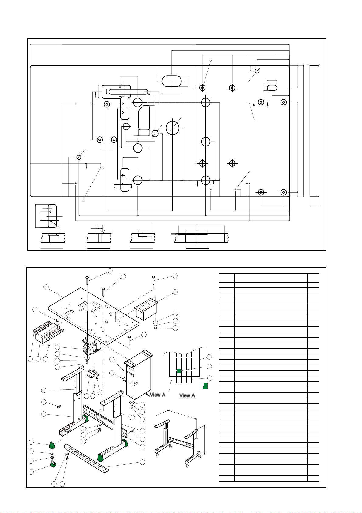
APPENDIX
Tabletop and stand drawings.
Ref.1 ···············Table cut-out for PLK-E1010 machine
Ref.2 ···············Table and stand
Ref.3 ···············Stand components
NOTE Tabletop and stand must be produced refer to below drawings.
Recommendable measurements for original MITSUBISHI tabletop and stand are
shown in the figures.
― 40 ―
Page 46
2
Ref.1 <Table cut-out for PLK-E1010 machine>
C
φ40
70
13
D
48.5
110
φ
50
E
80
C
145
C
161
14
60
23
57
D
A
358
260
178
60
10
104
40
32
Section B
38
2-φ7
8
159
A
9
1
φ
66
For air regulator
installation
φ26
φ9
Section A
66
130
273
60°
82
2-φ4
40
B
E
323
143
4
97
53
69
B
B
A
B
1
Section C
1200
30
210
805
314
545
138
4-φ9
100
50
A
90
C
φ60
340
C
235
A
174
C
C
C
84.5
51
4
48.5
129
A
350
A
74
115
265
25
9
1
φ
A
4-φ2.5depth16
(underneath)
358
For switch installation
60
33
250
388
150
45
25
80
A
A
A
27
105
185
C0.5
C
100
590
405
A
20
41
Section D
Ref.2 <Table and stand>
1
26
24 23 25
20
16
17
18
2
6
27 28
29
3
10
11
12
13
9
8
16
17
18
22
15
15
Fig.No Description Q ty.
1 Table T op 1
21
2Stand (A) 2
3Stand (B) 2
4 S upport fram e (A ) 1
5 S upport fram e (B ) 1
16
17
18
15
Note: Apply rubber plate
to a control box
6Bolt w ith S W - P W (large) M 8x20 6
7Bolt w ith S W - P W (sm a ll) M 8 x 2 0 4
8Bolt w ith S W - P W (m iddle) M 8x20 2
9Wide-rim m ed w asher (large) 8 2
10Pedal 1
11 Shaft 1
12 Shaft housing 2
13Collar 2
14
14
19
14Bolt w ith S W M 8 x 2 0 2
15T nut M8 2
19
16 T op cap 4
17Washer M124
3
18 Spacer 4
19Caster 4
20 W ood screw 5.8x32 4
21 Control box 1
16
17
2
18
3
7
4
8
5
3
805
720
800
22 M ounting bolt M 8 x 6 0 8
23 W ide-rim m ed w asher (large) 8 11
24 W ide-rim m ed w asher 8 11
25 N ut M 8 11
26 R ubber plate 1
27 M otor 1
28 P ow er box 1
~
29 M ounting bolt M 8 x 7 0 13
30 D raw er 1
mm
31 Rail2
32 W ood screw 4.5x38 4
5
33 S taple (L) 1
34 S w itc h ass e m b ly 1
35 W ood screw 4.1x162
36 S taple (S) 5
― 41 ―
Page 47

d
Ref.3 <Stand components>
18
95
9-φ11
120.3±0.5
65 60
182
(472.3)
470
A
A
119 63
H01
H02
No.
Description
Material
Surface Treatment
(40.3)
Caution
1
Stand (A)
H01: SPCC 2.3T
H02: SPCC 2.3T
101: WELD NUT M8
Paint(unti-corrosion)
String chamfer, except as noted
(chamfer slightly)
Trigonometry
2-φ6
(20)
128
358±0.5
270
9-Weld Nut M8
25 25
Section A
101
DIVISION OF DIM
to 100
over 100 to 300
over 300 to 1000
over 1000
LIMIT
±0.4
±0.5
±0.7
±1.0
20
39
2
Support frame (A)
SPCC 2.3T
Paint(unti-corrosion)
String chamfer, except as note
(chamfer slightly)
Trigonometry
4-φ9.5
80
120
115
10
18
DIVISION OF DIM
to 100
over 100 to 300
over 300 to 1000
over 1000
LIMIT
±0.4
±0.5
±0.7
±1.0
No.
Description
Material
Surface Treatment
Caution
18
130
38
805
841
130
10
4-φ9.5
― 42 ―
10
18
38
Page 48

5
30 30
25
(50)
25
+0.3
0
121
(60.5)
60.5
106
120
9
120
80
70
H01
H03
6 points
2-M12
No.
Description
Material
Surface Treatment
Caution
DIVISION OF DIM
to 100
over 100 to 300
over 300 to 1000
over 1000
3
Stand (B)
H01: SPCC 2.3T
H02: SPCC 2.3T
H03: SPCC 2.3T
H04: SPHC 4.5T
101: WELD NUT M8
Paint(unti-corrosion)
String chamfer, except as noted
(chamfer slightly)
Trigonometry
LIMIT
±0.4
±0.5
±0.7
±1.0
(560)
12
120
500
36.5
9
25
2-φ11
H02
101
22.5
60
10
2-φ9.5
10
25
4.5
44
50
LIMIT
17
25
No.
Description
Material
Surface Treatment
Caution
Support frame (B)
SPCC 2.3T
Paint(unti-corrosion)
String chamfer, except as noted
(chamfer slightly)
Trigonometry
17
25
155
(500)
345
DIVISION OF DIM
to 100
over 100 to 300
over 300 to 1000
over 1000
±0.4
±0.5
±0.7
±1.0
R2
R5
74
8585 32 20
10
85108
858520 20 8532
(108)
850
805±0.5
8
R4
48
48
22
R4
― 43 ―
Page 49

d
φ
2
2
M8ネジ
44±0.4
20
M8
No.
Description
Material
Surface Treatment
Caution
44±0.4
No.
Description
Material
Surface Treatment
SPHC 4.5T
6
Bolt with SW-PW (large)
M8 X 20
SS100
Electroplated Coating
Trigonometry
8
Screw plate (A)
Electroplated Coating
String chamfer, except as noted
(chamfer slightly)
Trigonometry
M8
No.
Description
Material
Surface Treatment
0
.
3
Surface Treatment
No.
Description
Material
Caution
φ
1
6
4
.
0
±
8
3
φ
2-φ10
20
φ
9
±
7
Bolt with SW-PW (small)
M8 X 20
SS100
Electroplated Coating
Trigonometry
9
Wide-rimmed washter (large)8
SPCC 2.6T
Electroplated Coating
String chamfer, except as noted
(chamfer slightly)
Trigonometry
120
R13
14.5 14.5
14.5
208
15
5
φ8
5
24
R30
60
85
134
φ12
2-C0.5
DIVISION OF DIM
0.5 to 3
over 3 to 6
over 6 to 30
over 30 to 120
φ9
over 120 to 315
over 315 to 1000
5
φ8
R10
13
R10
LIMIT
±0.1
±0.1
±0.2
±0.3
±0.5
±0.8
13
No.
5
Description
Material
Surface Treatment
Caution
No.
Description
Material
Surface Treatment
Caution
R13
DIVISION OF DIM
to 100
over 100 to 300
15
over 300 to 1000
over 1000
10
Pedal
SPCC 1.2T
Paint (unti-corrosion)
String chamfer, except as note
(chamfer slightly)
Trigonometry
11
Shaft
S15C
Electroplated Coating
String chamfer, except as noted
(chamfer slightly)
Trigonometry
LIMIT
±0.4
±0.5
±0.7
±1.0
― 44 ―
Page 50

d
φ8.5
R
1
No.
Description
Material
(4.5t)
Surface Treatment
Caution
7.5
40
5
0
9.5
-0.3
φ8
+0.3
20±0.2
11
0
30
9.5
15
R
2
R
2
12
Shaft housing
SPHC 4.5T
Elactroplated Coating
String chamfer, except as note
(chamfer slightly)
Trigonometry
DIVISION OF DIM
to 100
over 100 to 300
over 300 to 1000
over 1000
LIMIT
±0.4
±0.5
±0.7
±1.0
M6
No.
Description
Material
Surface Treatment
0.5 to 3
over 3 to 6
over 6 to 30
13
Collar
NYLON 66
Trigonometry
LIMIT
±0.1
±0.1
±0.2
±0.3
±0.5
±0.8
20
No.
Description
Material
φ9
φ17
φ12
DIVISION OF DIM
2
7
over 30 to 120
over 120 to 315
over 315 to 1000
14
Bot with SW M8X20
SS100
Elactroplated Coating
Trigonometry
M8
3
R
-
4
25±0.4
14
3
R
-
2
(4.5t)
No.
Description
Material
Surface Treatment
Caution
No.
Description
Material
15
Screw plate (B)
SPHC 4.5T
Elactroplated Coating
String chamfer, except as noted
(chamfer slightly)
Trigonometry
16
Top cap
RUBBER(NBR)
Trigonometry
DIVISION OF DIM
over 3 to 6
over 6 to 10
over 10 to 18
over 18 to 30
over 30 to 50
over 50 to 80
over 80 to 120
over 120 to 180
to 3
LIMIT
±0.3
±0.4
±0.5
±0.6
±0.8
±1.0
±1.2
±1.4
±1.6
49
+0.5
50
3
-0.2
3
3
3
R
R
6
5
23
7
3
R
-0.2
+0.5
60
6
46
39
8
28
― 45 ―
10
Page 51

φ
.
2
1
φ
2
1
.
5
6
.
0
+
0
2
No.
Description
Material
Surface Treatment
5.8
H01
21.5
17
Washer 12
SWRH62~72
Elactroplated Coating
Trigonometry
32
4.2
8.4
No.
Description
Material
Surface Treatment
No.
Description
Material
20
Wood screw 5.8X32
SWRMv3
Elactroplated Coating
Trigonometry
18
Staple (L)
SWM-N 2.3D 2003
PVC coating
Trigonometry
10
2.3
17
SWM-N 2.3D 2003
No.
29
24
5
7
φ
H02
No.
Description
Material
Description
Material
M12
35
95
21
Drawer
H01. Front : Lauan board (Plywood) B-Z melamin coated
H02. Side : Lauan board (Plywood)
H03. Side : Lauan board (Plywood)
H04. Back : Lauan board (Plywood)
H05. Bottom: Lauan board (Plywood)
Trigonometry
19
Caster
RUBBER WHEEL
Permitted load: 40Kg (per each)
Lock mechanism is requireda
Trigonometry
CASTER
415EA-Rφ75(HAMMER)
H04
H03
12
11
23
4
C
1
No.
2-φ4
Description
Material
364
375
342
350
340
252
22
Rail
H01. Front : Lauan board (Plywood)
Trigonometry
H05
44
10
10
4
C1
11
25
10
4.5
8
6.5
11 4
4
15.5
6
6
C1
140
120
128
No.
Description
Material
Surface Treatment
4
4.5
38
23
Wood screw 4.5 X 38
SWRM3
Elactroplated Coating
Trigonometry
95
― 46 ―
Page 52

MITSUBISHI ELECTRIC CORPORATION
FACTORY AUTOMATION SYSTEM
OFFICE TOWER “Z” 14F 8-12 1chome, Harumi CHUO-K U, TOKYO 104-6212, JAPAN
Phone : +81-3-6221-6060 Fax : +81-3-6221-6076
New publication, effective SEP.2001. Contents subject to change without notic
e
 Loading...