

Page 1
MITSUBISHI
.=:i!I~JJ)~~::,JDlti~B)J.
~y~:ffj!f~*i
Industrial Sewing Machine I Mechanical Version I
c.:r/{~~:/'&v
Electronic
PLK
(JAilit/"'
(Wide-area Perfect Stitch Specifications)
;:.
O)~I~IH!IJ:fJ,~tj~IYHif0)}3rjffit
i!i :a:$
This
manual, so please refer to
within.
-B****-GL
--7
!ffi
<
f(_
~
instruction
Pattern
::r:..-7
v \
manual
~.A
has
'~V:/'
Sewing Machine
7~7-ftt.)t)
~
!..-
been
the
-cmJJX:
prepared
standard
!..-
-cto
1:J
as a
supplement
instruction
~
TO)'"f',
manual
~[!*IG*lJ:£H'1-IJ:fJ,~tj~IY'J
to
the
for
standard
matters
instruction
not described
A180E471P01
Page 2
[I]
ttO)JDli.Ji'J'rtn-,
ktO)iiL.,n
Installing the needle,
and
threading the thread
Caution
*~C7)1C~,
*fi1;t75~~tJ;ti'l!iii~MtL,
*Always turn the power OFF before replacing the needle or threading the thread through the
needle eye.
*Please
~~~*:a-im-t-~l:;t,~Z,"f'mli:?.-1':;;7-:a-m-::>-c<t;:~v'.
pay attention
?-71:a-t...t.t:v
for
the fingers not to
\l:?l~tt;tL.
be
(
(2)
1)
-c<t~~v
wounded
1)
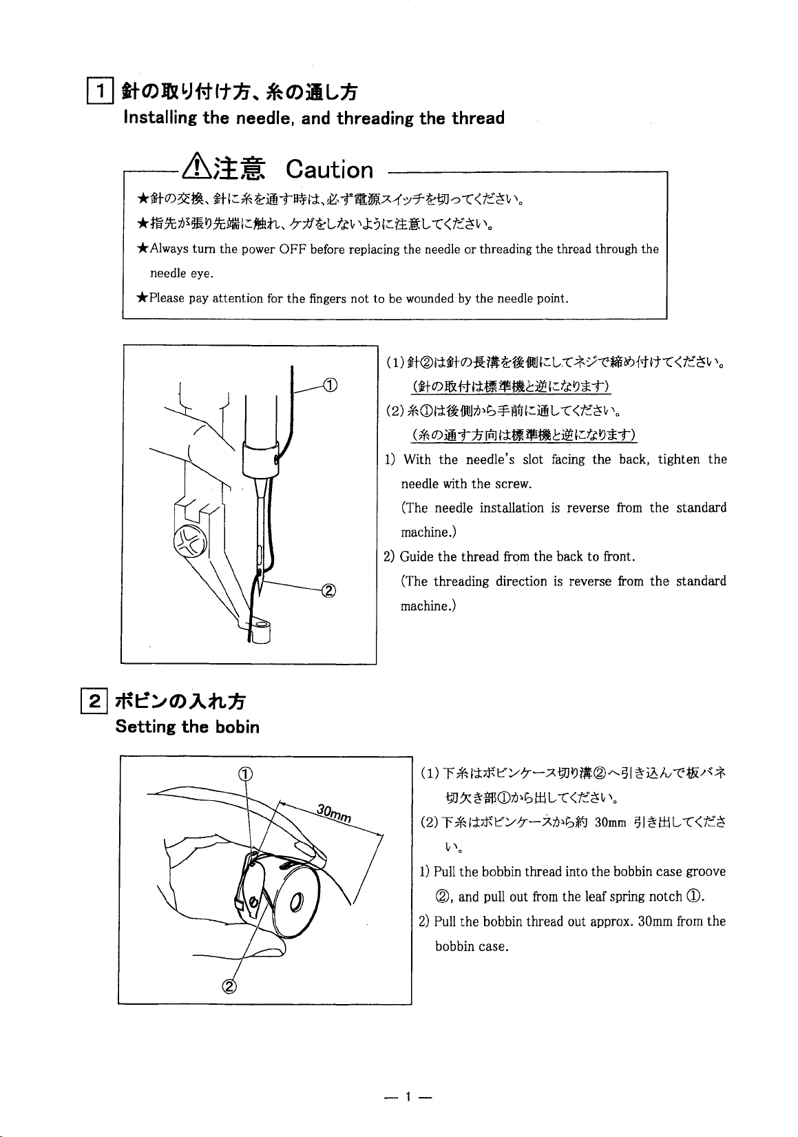
ft®l:;titC7)-B:$~~iJJI~L.:-t"-*V:-z>.~f-t~t-c<t;:~lt
(ij-O)J&{-J-I:;t~$-b~l~f.t:t'J*'T>
*<DI:;t~J.IJ;O~t,-¥iVJI~imL.
<*
C7)JiT1.7JP.l
With the needle's slot facing the back, tighten
needle with the screw.
(The needle installation
'·
by
the needle point.
l:;tfl$tl~~
-c<t~~v'.
l~t.t:t'J*'T>
is
reverse
from
the
'o
the
standard
[I]
~t::~O).Ann
Setting
the
bobin
machine.)
2)
Guide
the
thread
(The threading direction
machine.)
<1>
r
*':;t~t:·:Y-7-?.;~JtJfl®,..,.51~iblv-z-~/~*
;~J.X~$<D75~t>I:I.1L.
(2)
r
*':;t~t:.:Y-7-~;0~t>~
1)
Pull
the
®,
and pull out
2)
Pull
the
from
bobbin thread into
bobbin thread out approx. 30mm from
the back
from
to
front.
is
reverse
-c<t;:~v'.
the leaf spring notch
from
30mm
the
bobbin case groove
the
standard
51~1:1.1L.
-c<t;:~
<D.
the
bobbin case.
-1-
Page 3
~····
Standard adjustment
.----~5!il
*3::.-<:/~Wij~TQ#J{HJ:,~,-f.A-1::r7~
*1[7m{.A-1;:;7
JE~iJ~Gii~'~t-cW/iJ~L-
**,
tfl~O))ttlffii""t:-7-:tf~L-ftlt
*Wij~~~~l&IJ~L-t;:*~J:.O)f*~~~
-;JJ-p-~)
*Please
*If
*Be
*Please
make
the adjustment
from
the foot.
careful not to be wounded
make
guard etc.) back
Adjustment
of
ON
1-.tiJM~~T~~,
sure to turn the power
sure to put the safety guards
on
the
position between the needle
Caution
OFF
L-
-c<t::~v'o
O):JX~""t:Wij~TQ~,~iJ~thQ#J{Hi,
-c
<t::~v
'o
'J:%:l'±.i':L-
~,-f~iml'JI~l&ftft-c<t::~v'o
switch
is
required under the power switch
by
the needle or the inner hook point.
the original location after the
-c<t::~v
(7
-1:1f-J'',
OFF before adjust the
(Eye
guard, Belt guard,
sewing
and
the shuttle
.A?-'-J,.A-1::;7-
'o
.r-::;v]-.;iJ/-\-,
is
ON,
keep the start
machine adjustment.
hook.
lJ/:l:;f.J/-\-,
sewing
machine.
Link
(7;:;r.A-1:;;7)
7
4/:1J
foot
switch
away
cover and finger
~
(1)
1[7Jj{.A.-{y7~
C2)
7'-IJ
~-=F"t:'lEJL-
jfcL-td1z:~®"t:'
(3)
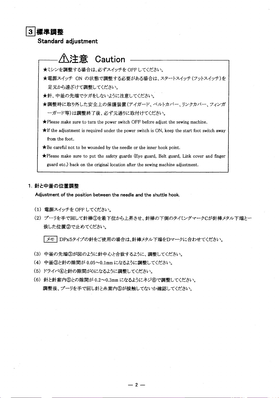
lfl~O))t;Mff@il~~O)J:?I~*Ifl•L.'C:~~TQJ:?I~,
(4)
!fl~®c*O)~rdliJ~
(5)
1''7-1'
/"@c*O)~r~,iJ~ol~ttQJ:?I~WMmL-
(6)
*.!::~~Fkl@cO)~r~9il~
W/3~~,
7'-.!J~-¥"t:'lEJL-*.!::*~Fkl@il~ti€~L-
OFF
L-
-c<t::~v'o
-c*•<D~• r {1z:iJ~GJ:.~~-tt,
11::~-c<t::~v
0.05'"'-'0.lmm
'o
l~ftQJ:?I~WM~L-
0.2""'0.3mm
l~ftQJ:?I~;:t.:./@"t:'WWJ~L-
*•O)r1JtiJO)?T-13:/:7"-;>"-:7cn~*•}?T
JIMJ~L-
-c<t::~v'o
-c<t::~v
-c<t::~v
'o
-cttv'i6~1it~L-
'o
-c<t::~v'o
-c<t::~v\
;v
rMffC:-
-2-
Page 4

1)
Turn the power switch OFF.
2)
Turn the sewing machine pulley
the
stop it at
bottom line.
position ® where
by
hand then, move
the
needle bar timing mark C
up
the needle bar
is
matched
CD
from
the lowest position and
to
the needle bar bushing
NOTE I
3)
Adjust so that the end of the inner hook @
4)
Adjust so that the clearance between
5)
Adjust so
6)
Adjust with
Mer
adjusting, turn the pulley by hand, and confirm that
contact.
If
the needle class
bottom
that
screw@
line.
the clearance between
so that the clearance between the needle and needle
is
DPx5,
match the needle bar
is
aligned with the center of
the
inner
hook@
the
driver®
and needle is 0.
D~
~"'c
timing
and needle
the
mark
D to the needle bar bushing
the
needle.
is
0.05
to
O.lmm.
guide@
needle and needle guide @
is
0.2
to
0.3mm.
do
not
3
-3-
o.os~o.lmm
Page 5

Adjustment
( 1)
rtl?t'R@~.J&IJ71-L-
(2)
.*~J7'J®~it@~O){lz:iW:~f*l'i~O)J:?I;:tj>!>J:?Wiii~L-
(3)
Wlii!IH~
1)
Remove
2)
Adjust so that the positional relation of
drawings.
3)
After adjusting, insert the
original positions.
of the
l'i!J
/:7CDJ\:
the slide
thread
guide
-c<t~~v
l;:~t!JJ:A@O)t:"::..--tm~tt¥A
plate@.
'·
pin
section of the moving
-c<t~~v
L-
-c
~iffi
I?
the
needle guide @ and needle @
knife
'·
1::.1&
I?Htt-c
<t~~v
® into the link hole
'·
is
as shown
CD,
and install to the
in
the
Moving
(l)f$lf:~O)~t!Jj:A(DI'itltl?t'RJ\:$;O~G~l
1)
knife
stopping
Adjust so that the moving
position
knife
mm
1±1-!>J:?I::Wii)~L-
CD
protrudes approx. lmm from
-c<t~~v'.
-4-
the
slide plate hole when stopped.
Page 6

PLK-B * * * *
-GL
SIS&'l./PLK-8 * * * *
-GL
Parts
~
~21
·~
1
2
3
4
12
13
14
15
·-~
6
7 8 9
10
16
-5-
Page 7

PLK-B * * * *
Fig.
8illi::J-
No.
Parts.
901
MB25F0580
1 MB10F230
2 MB25F1230
3 MB25F0230 ..tfi · · · · · · · · · · · · ·
4 MB35F0230
5 MB25F0125
6 MB25F0616
7 MB25F0120
902
MB25F1611
8
MB25F0611
9 MB25F0103
903 MB10F1121
904
MB25F1121
905
MB45F1121
MB35F1121
906
10 MB25F0121
11
MB25F0329
907 MB10F0470
908 MB25F0470
909 MB25F1470
910 MB34F0470
-
12 MB10F0472
13 MB25F0472
14 MB25F1472
15 MB35F0472
16 MB25F0838
17
MB25F0834
18 MB25F0910
19 MB10F0910
20 M91802006
21
M91520001
22 M90806002
t:
No.
-GL
:;lli;;ff/\
IJ
? M · · · · · · · · · · · Thread take-up lever
..t•
· · · · · · · · · · · · · · · · · · · ·
..t.
· · · · · · · · · · · · · · ; · · · · ·
..t•
· · · · · · · · · · · · · · · · · · · ·
;f.
t:'
~
"T-
lflji~jt
lfl
t:
t:
itlilt~
~UUI.li
*iiM.li
*itM.lt
*itM.lt
*it····················
ii!t'tlilt~
;t
it~)
it~)
it
it~)
it~)
;t
it
Jil2
811J)l
IJ
IJ
t:
t:
t:7;t..~
· · · · · · · ·
it
· · · · · · · · · · · · · · · · · · · · Inner
7-(
1 \M:ii · · · · · · · · · · ·
7-(
1\
· · · · · · · · · · · · · · ·
· · · · · · · · · ·
· · · · · · · ·
· · · · · · · · · · · · · · · Outer hook assy ·
· · · · · · · ·
· · · · · · · ·
· · · · · · · ·
~)
tiM.lt · · · · · ·
tiM.lt · · · · · ·
tiM.li
~J
tiME
5 · · · ·· · · ··· ·
4i
· · · · · · ·
~J
4i ·
........
~)
4i .. · .. · · · · ·
)l
A · · ·
A
..............
~?
.................
~?
.................
7:t-~tf:S'c
7:t-~
...............
...............
Sii/PLK-B
Ann
(drive) shaft· · · · · · · · · : · · · • · • • · ·
Ann
(drive) shaft· · · · · · · · · · · · · · · · · · ·
·······Ann
A · · · · · · · · · · ·
·······Hook
·······Needle
·······Outer
·······Outer
·······Outer
·······Thread
·······Slide
·······Slide
· · · · · · · · · · · · · Slide plate
· · · · · · · · · · · · · Slide plate
······Slide
.....
·····Slide
· .. · · · · · Slide plate· · · ·
....
..
· · · · ·
..
.. ··
.......
(drive)
Ann
(drive) shaft· · · · · · · · · · · · · · · · · · ·
Bobbin
case
retaine · · · · · · • · · · · · · · · · · · · · · ·
hook
Hook
driver assy · · · · · · • · · · · · · · · · · · · (1)
Hook
driver···:······
guide ·
hook assy · · · · · · · · · · · · · • · · · · · (1)
hook assy •
hook assy ·
Outer
hook························
guide · · · • · · • · · · · · · · · · · • · · · · 1
plate
plate
plate"
plate····
· · · Slide plate
· • · Fixed
knife
·Movable
Link
.............................
Link
............................
Screw
...........................
Screw 15/64(18)X 12
Screw1/8(44)X6
* * * *
Description
shaft···················
· · · · · · · · · · · · · · · · · • · • · · ·
· · · · · · · · · · · · · · · · · · · · • · · · 1
··
· · · · ·
..
..
..
assy·
· · · • · · · · · · · •
assy·
· · · · · · · · · · · · · • · · • · ·
assy
· · · · · · · · · · · · • · • · · · · ·
assy
· · · · · · · · · · · · · · · · · · · •
.....................
..
··
.... · ......
..
· · · · · · ·
· · · · · · · · · ·
knife"'
.................
-GL
assy
· · · · • · · • · ·
· · · · · • · · · · • · · •
·· ·· · ·•·•·
· · · · · · · · · · • · · · · ·
· · · · · · · • · · • · • • · •
· · · · · · · · · · · · • · · ·
..
• · • · • (1)
......... · .. · ..
· · ·
..
· •
..
· • · · · · ·
..
· · · · ·
..
· • · · ·
..
· · ·
..............
.................
· ·
..
Parts
fiJI! Ill!!
Amt.
Req.
1
(1)
(1)
(1)
2
2
84516 83530
1
(1)
(1)
(1)
2
2
81006 82516 86019 86030
•·
1
..
··
·
..
..
.
..
.
2
2
-~::I-
Ref.No.
W34979o-G04
A1218758H01
A121B754H01
A133C993H01
A121B812H01
A 1900899P01
A133C997H01
1
A 190D898P01
(1)
A147D110G01
A1218751H01
A146D967H01
A134C190G01
A 134C190G02
A134C190G03
(1) A134C190G04
A
121
B752H01
A 133C998H01
A 133C994G04
A133C994G01
A
133C994G02
(1) A133C994G03
A1218844H01
A 133C995H04 #2
A134C014H01 #2
A1218813H01 #2
A146D645H01
A146D636G01
A 146D638H02
A146D638H01
B503851-H01
1
A1410751H01 #4
2
2
8508857-H01
t:
#1
#3
.:it
#1
: PLK-81006
#2 :
#3:
#4:
1
A.;(
J -( ~ ( lfl) (})h-.
?7~?-t!•:J
-:1-•J
(V;(JL-
JIIA;(
•J-(
I-JIIA;(7;Qt:..
1-)
i!'!l
~
lfl ·
*-f*~.
I-JIIA;(7;Qt:.
Remarks
#1 : Whole
#2 : Separate plate type.
#3
#4 : Spare screw for
plate
type.
: Spare screw for crank.
pulley.
-6-
Page 8

i'llD-0005
ll!ll!e'fttiBIZJILO>PI2-2-3C.:JI:tat::M
•*
•t,<S~I:11'Fii1i
:::ll)I'!Jli\IJ411JI:l:,
Printed
:t±
:;=100-0005
:;=461-D048
19991f'.ll JHW'-c.'T, t;::t.;, t>llli'J
in
Japan
(MEE)
:!!.iS~iP~IR;;Bl~
9911
:!IDf-tll'fft8l!R;iJ.O)~
~MITSUBISHI
HEAD'OFFICE:
MITSUBISHI DENKI BLDG. MARUNOUCHI, TOKYO 100
2-2-3
(.:::Jfil:!llt:J~)
5-1-14
t,i!;~(052)712-2208
tt
U::f.t<R~lll:'l!-;-<>:::
ELECTRIC CORPORATION
TELEX:
J24532
~jf-(03)3218-3522
1::
1li3?
IJ
-:1;-j-ll)-c.':::"T:iJ:<
t::~;',
CABLE:
MELCO TOKYO
1999
~
11
J=H'!=P!
 Loading...