

Page 1

MITSUBISHI
Industrial Sewing Machine
TECHNICAL MANUAL
MECHANICAL VERSION
Electronic Pattern Sewing Machine
Model PLK-B 1 008H
A
180E463P01
Page 2
2.
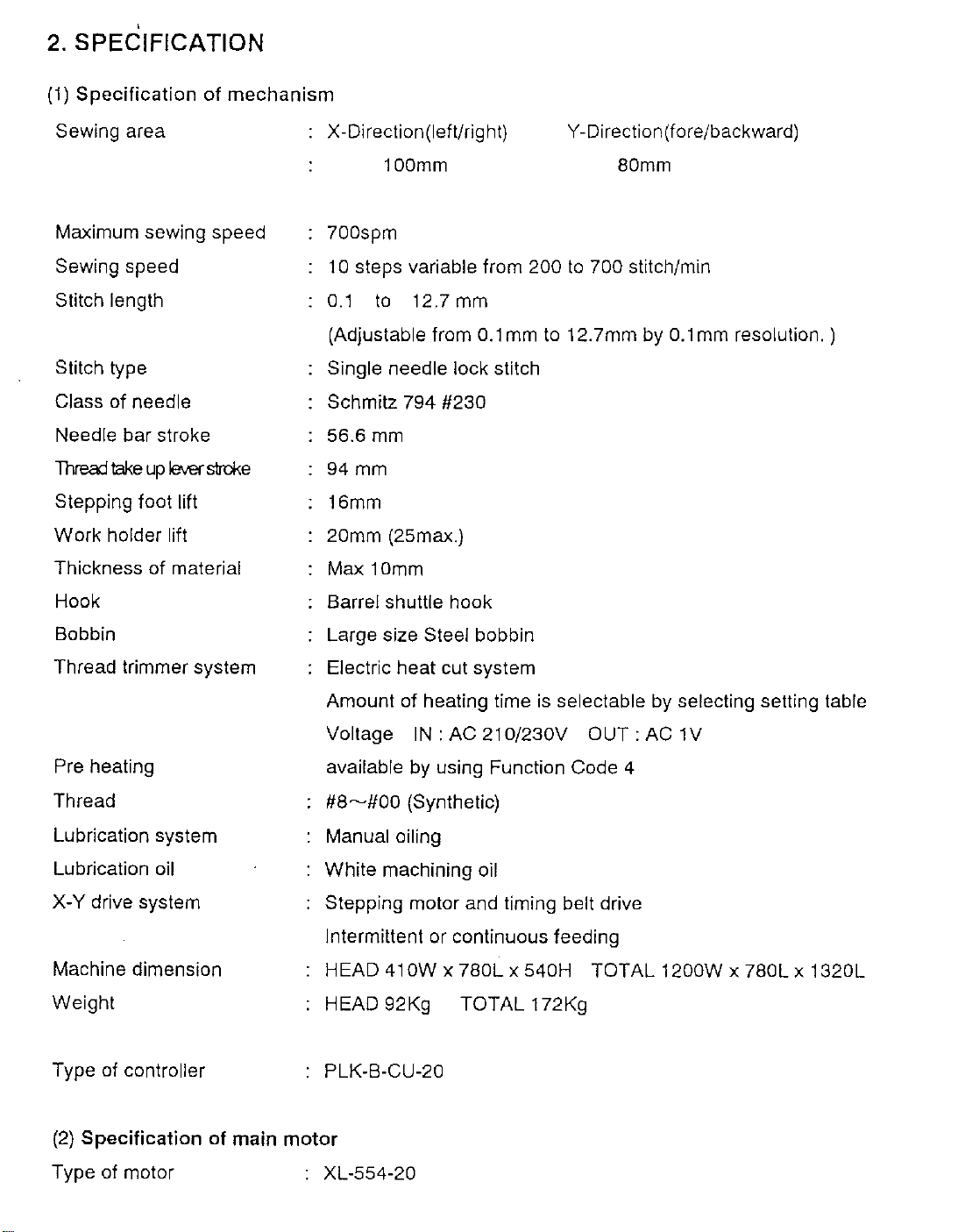
SPECIFICATION
(1)
Specification
Sewing area X-Direction(lefl/right)
'
of
mechanism
Y-
Direction (fore/backward)
Maximum sewing speed
Sewing speed
Stitch length
Stitch type
Class of needle
Needle bar stroke
Threaj
Stepping foot lift
Work holder lift
Thickness of material
Hook
Bobbin
Thread trimmer system
take
up
lever
stroke
100mm
700spm
1 o steps variable from 200
0.1
to
12.7 mm
(Adjustable from
Single needle lock stitch
Schmitz 794
56.6
mm
94mm
16mm
20mm (25max.)
Max
10mm
Barrel shuttle hook
Large size
Electric heat cut system
Steel bobbin
#230
0.1
mm
to
80mm
to
700 stitch/min
12.7mm by
0.1
mm
resolution.)
Amount of heating time
Voltage
Pre heating
Thread
Lubrication system
Lubrication
X-Y drive system
Machine dimension
Weight
Type of controller
(2)
Specification of main motor
Type of motor : XL-554-20
oil
available by using Function Code 4
#8~#00
Manual oiling
White machining oil
Stepping motor and timing belt drive
Intermittent or continuous feeding
HEAD
HEAD 92Kg TOTAL 172Kg
PLK-B-CU-20
(Synthetic)
41
OW x 780L
IN:
AC 210/230V
is
selectable by selecting setting table
OUT:
x 540H TOTAL 1200W x 780L x 1320L
AC 1V
Page 3
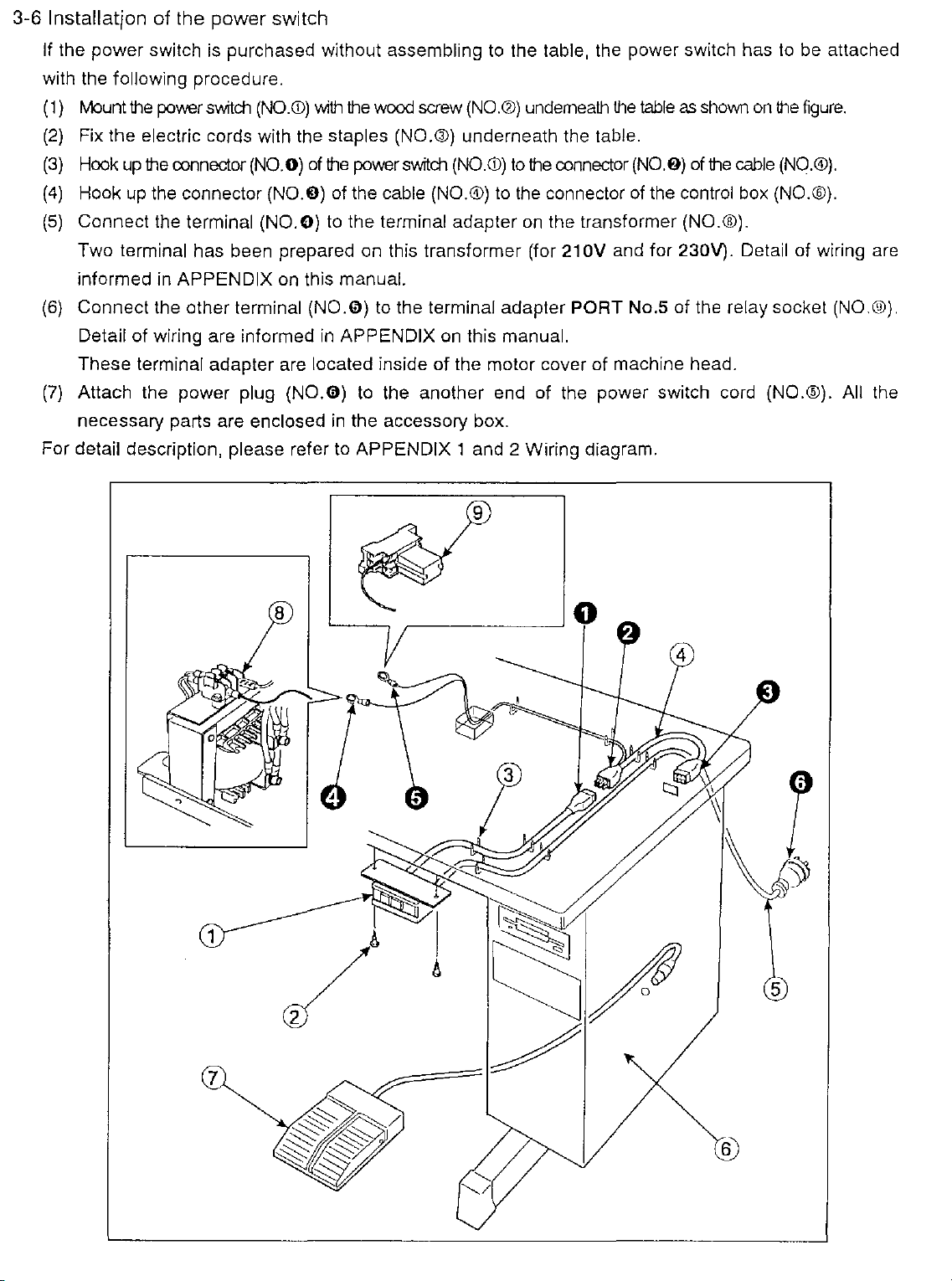
3-6
Installation
of
the
power
switch
If the power switch
with the
1}
(
(2}
(3}
(4}
(5}
(6}
(7}
For
following procedure.
fvlount
Fix the electric cords with the staples (NO.®) underneath the table.
Hook
Hook
Connect the terminal (NO.O}
Two terminal has been prepared on this transformer (for
informed
Connect the other terminal
Detail
These terminal adapter are located inside
Attach the power plug
necessary parts are
detail description, please refer to APPENDIX 1 and 2 Wiring diagram.
the
power
up
the
up
the connector (NO.O) of the cable (NO.®)
in
of wiring are informed
is
purchased without assembling
switch
oonnector
APPENDIX on this manual.
(NO.<D)
(NO.O)
enclosed
with
of
(N0.0)
(N0.0)
the
wood
the
power
to
the terminal adapter
to
in
APPENDIX
to
the another end of the power switch cord (NO.®). All the
in
the accessory box.
to
the table, the power switch has
screw
(NO.@}
switch
(NO.<D)
the terminal adapter PORT No.5 of the relay socket (NO.®).
on
this manual.
of
the motor cover of machine head.
underneath
to
the
to
the
on
oonnector
connector
the transformer (NO.®).
21
OV
the
table
as
shown
(N0.6)
of
and for
of
the control box (NO.®).
230V).
on
the
cable
Detail of wiring are
to
be attached
the
figure.
(NO.®}.
Page 4
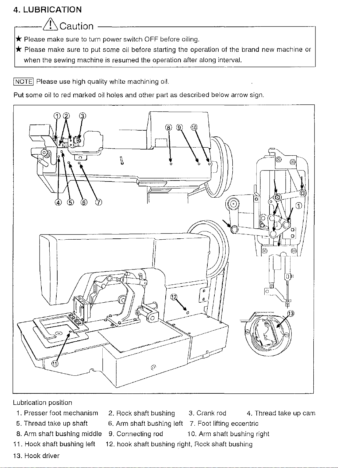
4. LUBRICATION
,----&Caution
* Please make sure
to
turn power switch OFF before oiling.
* Please make sure to put some oil before starting the operation of the brand new machine or
is
when the sewing machine
I
NOTE!
Put
Please use high quality white machining oil.
some oil to red marked
resumed the operation after along interval.
oil
holes and other part as described below arrow sign.
0
=
I
Lubrication position
1 .
Presser foot mechanism
5.
Thread take up shaft
8.
Arm shaft bushing middle
11. Hook shaft bushing left
13. Hook driver
2.
Rock shaft bushing 3. Crank rod
6.
Arm shaft bushing left
9.
Connecting rod 10. Arm shaft bushing right
12. hook shaft bushing right, Rock shaft bushing
7.
Foot lifting eccentric
4.
Thread take up cam
Page 5
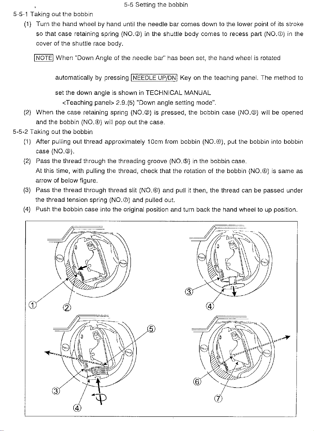
5-5-1 Taking out the bobbin
(1)
Turn the hand wheel by hand until the needle bar comes down
so that case retaining spring
cover of the
shuttle race body.
5-5 Setting the bobbin
(NO.®)
in
the shuttle body comes
to
the lower point of its stroke
to
recess part
(NO.CD)
in
the
I NOTE I When "Down Angle of the needle bar" has been set, the hand wheel
automatically by pressing I NEEDLE UP/DNI Key on the teaching panel. The method
set the down angle
<Teaching
(2)
When
and the bobbin
5-5-2 Taking out the bobbin
(1)
After pulling out thread approximately
case
(2)
Pass the thread through the threading groove (NO.®) in the bobbin case.
At
arrow of
(3)
Pass the thread through thread slit (NO.®) and pull
the thread tension spring
(4)
Push the bobbin case into the original position and turn back the hand wheel
the case retaining spring (NO.®)
(NO.®) will pop out the case.
(NO.GJ).
this time, with pulling the thread, check that the rotation of the bobbin (NO.®)
below figure.
is
shown in TECHNICAL MANUAL
panel> 2.9.(5) "Down angle setting mode".
is
pressed, the bobbin case (NO.®) will
(NO.<V)
1Dcm
and pulled out.
from bobbin (NO.®), put the bobbin into bobbin
it
then, the thread can
is
rotated
be
opened
is
same as
be
passed under
to
up position.
to
5
Page 6
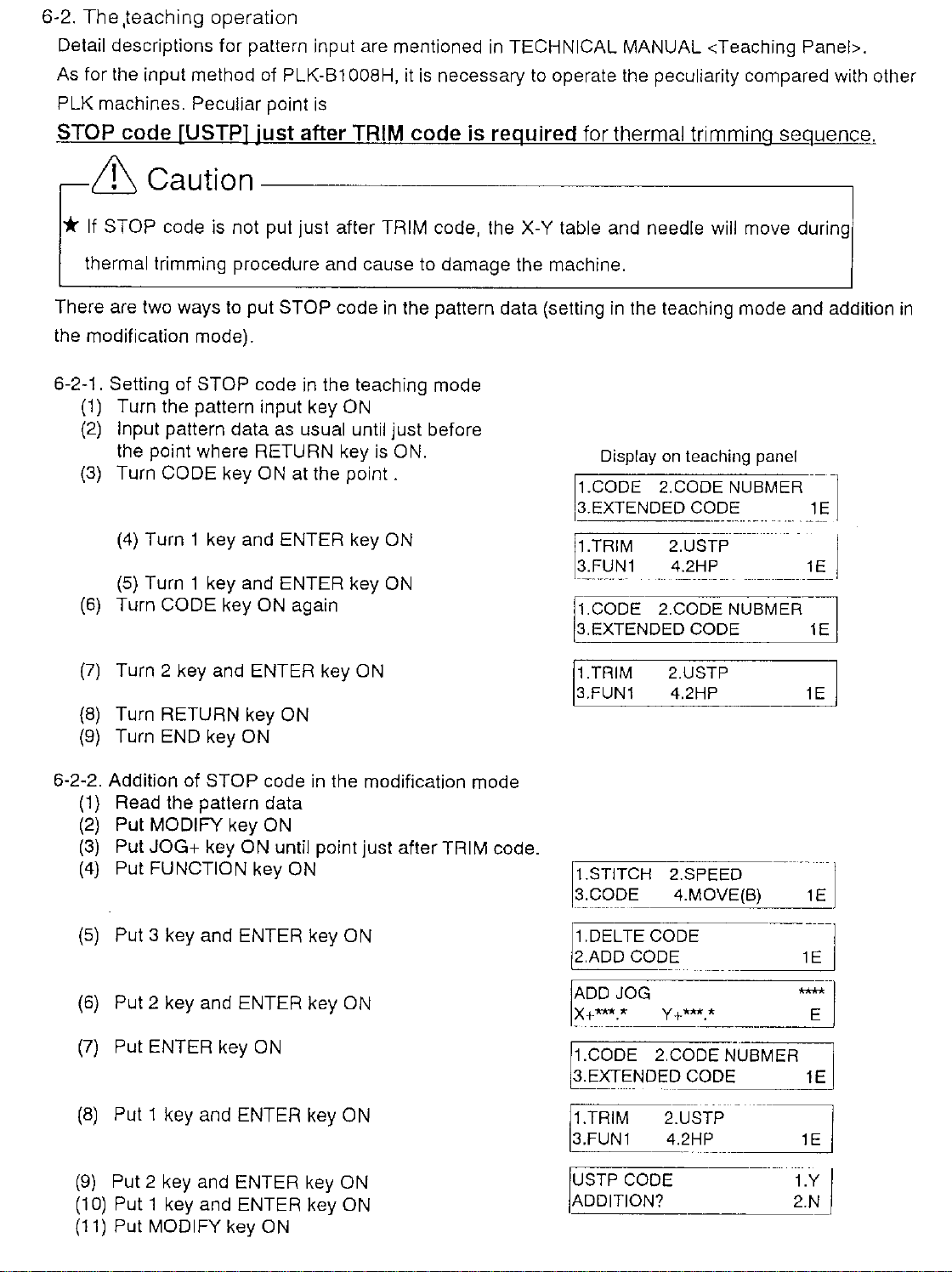
6-2.
The
,teaching
Detail descriptions for pattern input are mentioned
As for the input method of PLK-61 008H, it
PLK machines. Peculiar point
operation
is
is
necessary
in
TECHNICAL MANUAL <Teaching Panel>.
to
operate the peculiarity compared with other
STOP code [USTP] just after TRIM code is required for thermal trimming sequence.
&
* If STOP code
thermal trimming procedure and cause to damage the machine.
There are two ways to put
the modification mode).
6-2-1. Setting of
(1)
(2)
(3) Turn CODE key
(6)
(7)
(8)
(9)
Caution--------------------,
is
not put just after TRIM code, the
STOP code
STOP code
Turn the pattern input key
Input pattern data as usual until just before
the point where RETURN key
(4)
Turn 1 key and ENTER key
(5)
Turn 1 key and ENTER key
Turn CODE key
Turn 2 key and ENTER key
Turn RETURN key
Turn END key ON
ON
ON
in
the teaching mode
at the
again
ON
ON
is
point.
ON
in
the pattern data (setting
ON.
ON
ON
X-
Y table and needle will move during
in
the teaching mode and addition
Display on teaching panel
1.CODE 2.CODE NUBMER
3.EXTENDED CODE 1 E
-
1.TRIM
3.FUN1
1.CODE 2.CODE NUBMER
3.EXTENDED
1.TRIM 2.USTP
3.FUN1 4.2HP
~-----------
2.USTP
4.2HP
CODE 1E
----
--
·-·
.
-----
1 E
in
-~
I
6-2-2. Addition of STOP code
(1)
Read the pattern data
(2)
Put MODIFY key
(3)
Put JOG+ key ON until point just after TRIM code.
(4)
Put FUNCTION key
(5)
Put 3 key and ENTER key ON
(6)
Put 2 key and ENTER key
(7)
Put ENTER key
(8)
Put 1 key and ENTER key 0 N
ON
ON
in
the modification mode
ON
ON
1.STITCH 2.SPEED
3.CODE
1.DEL TE
2.ADD CODE
1.CODE 2.CODE NUBMER
3.EXTENDED
1.TRIM
~=~=:4=.2--HP
(9)
Put 2 key and ENTER key ON
(1
0)
Put 1 key and ENTER key ON
(11)
Put MODIFY key
ON
USTP CODE
ADDITION?
4.MOVE(B)
CODE
-
CODE 1E
2.USTP__
·-~~~
--~
~
2i._YN
I
Page 7
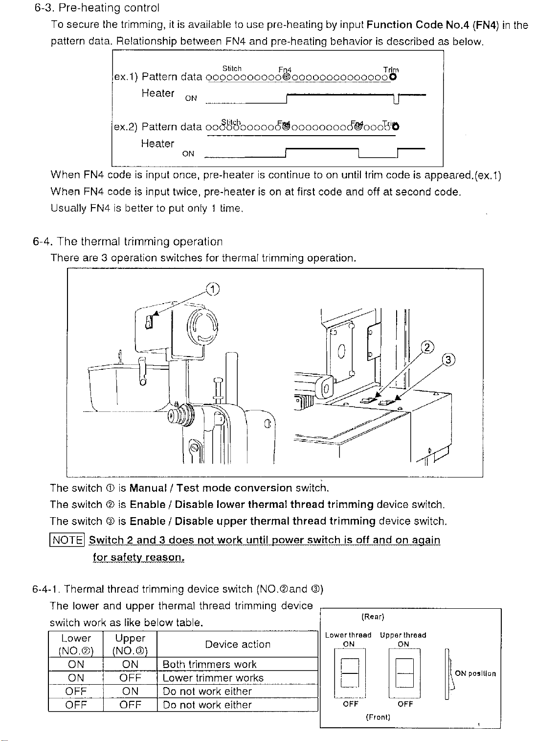
6-3.
Pre-heating
To secure the trimming, it
pattern data. Relationship between FN4 and pre-heating behavior
control
is
available
to
use pre-heating by input Function Code No.4 (FN4)
is
described as below.
in
the
ex.1) Pattern data
Heater
ex.2) Pattern data
Heater
When FN4 code
When FN4 code
Usually FN4
6-4.
The
thermal
There are 3 operation switches for thermal trimming operation.
is
input once, pre-heater
is
input twice, pre-heater
is
better to put only 1 time.
trimming
oN
ON
operation
Stitch
ooooooooooowooooooooooooooo
ooJ1'l't\'oooooo~ooooooooo@iooot5iO
Fu_4
is
continue to
is
on
at first code and off at second code.
on
until trim code
Trjrn
is
appeared.(ex.1)
The switch
The switch
The switch
I NOTEI Switch 2 and 3 does not wqrk
6-4-1.
Thermal thread trimming device switch (NO.®and ®)
Th I d
e ower
switch work as like below table.
Lower Upper
(NO.C?l)
ON ON Both trimmers work
ON OFF Lower trimmer works
OFF ON Do not work either
OFF
<D
is
Manual/
®
is
Enable I Disable lower thermal thread trimming device switch.
@
is
Enable I Disable upper thermal thread trimming device switch.
for safety reason.
an
upper
(NO.®)
OFF
Test mode conversion switch.
th
erma rea
Do not work either
unt[[_J!ower
I th d t . d
Device action
nmm1ng
lLWitg_~_.9lL1!nd
ev1ce
Low
or
thread Upper thread
ON
lgl
OFF OFF
on
{Rear)
ON
IB'
{Front)
again
~~
'"''"",.
'
Page 8
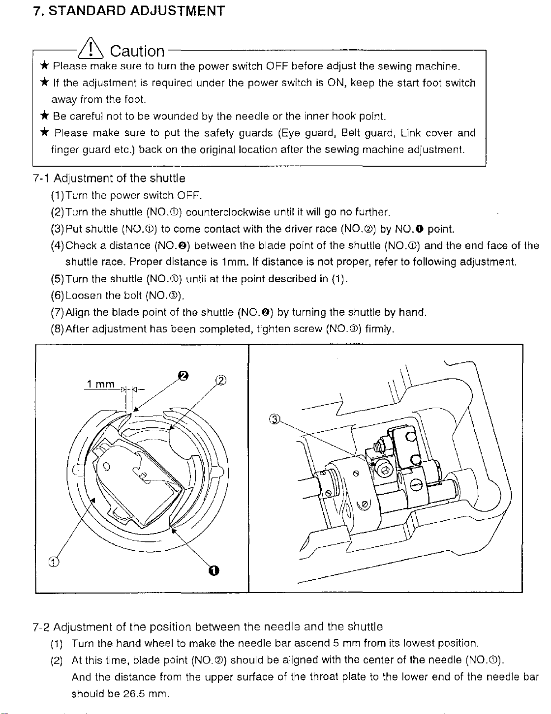
7.
STANDARD ADJUSTMENT
.----&
*Please
*
If
the adjustment
away from the foot.
*
Be
careful not to
*
Please make sure
finger guard etc.) back
Adjustment
7-1
(1
)Turn the power switch OFF.
(2) Turn the shuttle (NO.
Put shuttle (NO.!D) to come contact with the driver race
(3)
(4)Check a distance
shuttle race. Proper distance
(5)Turn the
(6)
Loosen the bolt (NO.®).
(?)Align
(B)
After adjustment has been completed, tighten screw (NO.®) firmly.
Caution--------------------,
make sure
of
shuttle (NO.
the blade point of the shuttle
to
turn the power switch OFF before adjust the sewing machine.
is
required under the power switch
be
wounded by the needle or the inner hook point.
to
put the safety guards (Eye guard, Belt guard, Link cover and
on
the original location after the sewing machine adjustment.
the
shuttle
!D)
counterclockwise until
(N0.6)
between the blade point of the shuttle (NO.!D) and the end face of the
is
1 mm. If distance
!D)
until at the point described in (1).
(N0.6)
by turning the shuttle by hand.
is
ON, keep the start foot switch
it
will go no further.
(NO.a>)
is
not proper, refer to following adjustment.
by
NO.O point.
3
1
7-2
Adjustment
(1)
Turn the hand wheel to make the needle bar ascend 5
(2)
At this time, blade point
And the distance from the upper surface of the throat plate
should be
of
26.5
the
position
mm.
between
(NO.a>)
the
should
needle
be
and
the
shuttle
mm
aligned with the center of the needle (NO.!D).
from its lowest position.
to
the lower end of the needle bar
Page 9
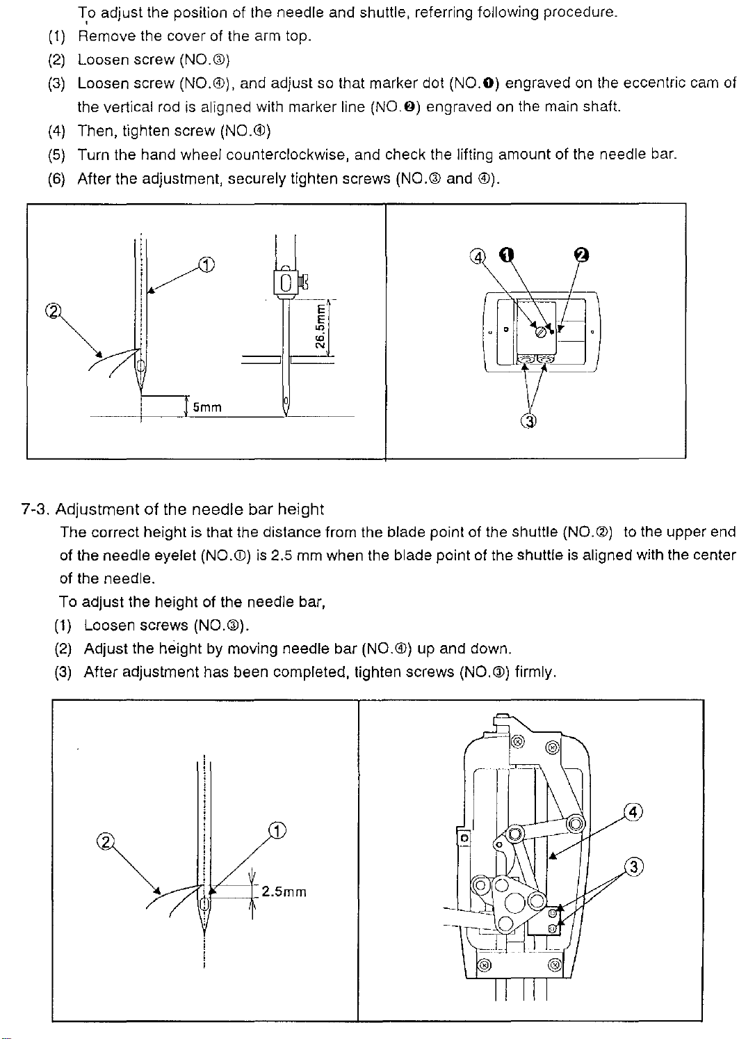
To adjust the position of the needle and shuttle, referring following procedure_
'
(1)
Remove the cover of the arm top.
(2)
Loosen screw (NO.Ql)
(3)
Loosen screw (NO.®). and adjust so that marker dot (NO.O) engraved on the eccentric cam of
the vertical rod
(4)
Then, tighten screw (NO.®)
(5)
Turn the hand wheel counterclockwise, and check the lifting amount of the needle
(6)
After the adjustment, securely tighten screws (NO.
is
aligned with marker line
(N0.6)
engraved on the main shaft.
Gil
and ®).
t\
bar_
/
0

7-4
Adjustment
To adjust the needle-to-shuttle clearance,
(1)
(2)
(3)
of
the
needle-to
Correct clearance between the recess
(NO.@)
is
0.25-
0.35
mm.
shuttle
clearance
in
the needle (NO.
CD)
and the blade point of the shuttle
Loosen screw (NO.®).
Adjust the clearance by moving shuttle driving shaft bushing (NO.®)
After adjustment has been completed, tighten screw (NO.®) firmly.
to
the left and right.
7-5 Adjustment of the needle-to-driver clearance
Correct
range of
clearance between the needle
0 -
0.05
mm.
(NO.CD)
To adjust the needle-to-driver clearance,
(1)
Loosen two screws (NO.®) and Bolt (NO.®).
(2)
Adjust clearance by moving the shuttle driving shaft (NO.®)
(3)
After
adjustment has been completed, secure the shuttle driving shaft thrust collar (NO.®) and
the small pendulum
(N0.0},
making sure there
5
and the needle guard of the driver (NO.@) has the
to
the left and right.
is
no axial play of the shuttle driving shaft.
,
..
0-0.0Smm
--
i
-------~-
Page 11

!The standard for adjusting the clearance between the needle and the blade point of the shuttle!
Use a standard
(1)
Adjust the clearance (NO.O)
to 0.
(2)
Align the needle center with the blade point of shuttle
needle against the driver
{3)
Adjust the clearance NO.O section to a minimum, with the needle
driver
shuttle
By
this adjustment the needle-to-shuttle blade point clearance
Schmelz
(NO.Cil).
(NO.®).
l.lJ
l
jctJ
794-Nm230 needle.
between/he
(NO.
cv).
making sure that the needle
convex section of needle
1.J
l
171
......
o!
V'
~0
IJ
·Lll
(NO.Q))
)V
(NO.Q))
(NO.@)
does not contact the blade point of the
and press the
(NO.Q))
will
be
0.25-0.35
and driver
N0.8
pressed against the
mm.
(NO.CV)
section of the
~
Pl
'
,IV
~
.
7-6
Test
mode
7-6-1. Entrance for the test mode operation
The test mode operation
of mechanical position (height or stroke) for the
thermal thread trimmer equipment and also
for check the position of the sensors of the
cylinders. For entrance this mode,
(1)
(2)
(3)
(4)
(5)
When the check of sensor
(Check input /output signal)
For enter E-mode,
(1)
operation
is
used for adjustment
Turn the power switch ON.
Put
on
the gray foot switch (clamp switch).
Put on the RESET switch on the teaching
panel.
Put on the gray foot switch again.
Reverse the mode conversion switch (NO.) to test mode position.
is
required
Put on the [f] key
in
the setting panel of the control
in
this operation mode, it
box.
NORMAl-MOO
POSITION
TEST-MOOEf
POSITION
is
available to enter the E-mode.
(2)
Put on the Up arrow key and
simultaneously over 3 seconds.
For description of the E-mode
Down
is
described
arrow key
in
the technical manual <CONTROL UNIT>.
on
the setting panel of the control box
Page 12

7-6-2. Key function
In
the test mode, each key on the teaching panel works to operate the thermal thread trimmer
in
the test mode
equipment
Relationship between the key and the
Key NO. Function
10
TENSION
RELEASE
lsroPPE~~
(cylinders or relay) independently.
equipment
1 Push/Pull the
2 Push/Pull the
3 Push/Pull the
4 Push/Pull the
5 Push/Pull the
6 Push/Pull the
7
8 Return the equipment to original position (Reset)
9
On
the Upper and Lower
1
cycle
Push/Pull the
KEY
FUNCTION in
TEST
1
g
LOWER
TRIMER
Tension
Thread
Wiper
Thickness
Lower
Upper
operation
Presser
MODE
5
8
release
puller
cylinder
trimmer
trimmer
detector
heater
foot
cylinder
cylinder
cylinder
cylinder
G;J
6
UPPER
TRIMER
is as below.
cylinder
cylinder
during 2
second
In
the Test mode, Start switch is disabled.
Each key function has
•:•
From
is up.
·:· KEY3 is disabled when Presser
•:•
From
is off.
•:•
KEY9
Presser
some
KEYO
KEY4
foot
to KEY9 is disabled when Clamp
to KEY6 is disabled when
is available when Clamp is down and
is up.
rule like below
foot
is down.
Wiper
[;;;]
0
PRESSEF
FOOT
I
RESET
11
CYCL:I
1
....
After
turning the
to normal-mode,
KETS(RESET) .
I NOTE I Reset method against the trouble
When
When
the thread trimmer device is stop by electrical problem (for example signal from sensor
does
program by
not
come), it
under
(1)
Put the
(2)
Change
(3)
Put the RESET key ON.
the thread trimmer device is stop by mechanical problem (for example jam with thread), it
necessary
is
with thread trimmer device.
HALT
mode switch to
to
is
possible to return the device to original position and reset sequence
mentioned method.
switch ON and turning back the
power
TEST
switch OFF. In this case the presser
mode.
I
HALT
switch to OFF.
mode
foot
conversion switch back
make
keep up to avoid interference
sure to put on
Page 13

7-7
Adjustment
7-7-1
(1)
(2)
(3)
(4)
of
the
presser
foot
Adjustment of the driving shaft arm(front) and the presser foot
Turn the power switch OFF
Remove the side cover and the face cover.
Turn the sewing machine pulley by hand and stop the driving shaft arm-rear(NO.lD)
maximum swing position in arrow direction.
Disconnect the presser bar lifting link (NO.®) from the presser lift plate
'
(NO.@)
by removing the
at
its
hinge screw
(5)
Lift up the presser bar (NO.®) and the hand lift link (NO.®).
(6)
Insert the 12.7mm block
(7)
Tighten the screw (NO.®) of the driving shaft arm-front
(NO.®) .
(NO.<Ll)
without the axial clearance of
the driving shaft.
{8)
After the adjustment, connect the presser bar lifting link (NO.®) with the presser lift plate
(NO.@)
by setting the hinge screw (NO.®) and put the face cover and the side
cover
the original location.
(9)
Loosen the screw (NO.®) of the presser foot (NO.®) and then, adjust the presser foot position
to be become the
the sewing
(1
0)
Tighten the screw (NO.®) of the presser foot with to come
material
clearance between the bottom surface of
o~o.5
mm.
down
the
presser foot and the surface of
to
the center of the needle hole
of the presser foot.
[Signal=
I D)
back
on
Page 14

7-7-2 Adjustment of the sensor of the presser foot cylinder
At
normal position, the sensor
At activate position, these sensor will
ID(NO.EJ)
be
is
ON and the sensor IE{NO.O) is OFF.
reversed.
Check the sensors by using
7-8 Adjustment
When tension close (the tension release plate
sensor
When tension open, (tension release plate approach to the tension disc), these sensors will
reversed.
Check the sensor
of
the tension release
IC(NO.®) on the cylinder
IB and
E-MODE (test mode)
(NO.GJ)
is
ON
and the sensor
IC
in
E mode and TEST MODE simultaneously.
leaves from the tension disc(NO.G:l)
IB(NO.GJ)
is
OFF.
),
the
be
7-9 Upper thread heat cut device
7-9-1 Setting thread puller
For a secure sewing at the seam beginning, a certain quantity of drawn-forward needle thread
required. The drawn-forward occurs after completion of seam with the clamps still lowered.
I Function sequence of Upper thread heat-cut procedure!
is
Page 15

-¢>
The sewing pattern
-¢>
The needle stops
-¢>
The presser foot lifted
-¢>
The needle thread tension open.
-¢>
The thread puller pulls the requiredthread quantity forward.
-¢>
The thread puller moves back into its base position.
-¢>
The needle thread tension close again.
-¢>
the thickness detector lowers
-¢>
The thread wiper pulls the drawn-forward needle thread into the
-¢>
heating position.
-¢>
The upper heater lowers.
-¢>
The thread is heated off.
-¢>
The clamp move up.
-¢>
A new sewing sequence can
The thread puller must
beginning
is
assured. If the drawn-forward thread quantity
is
finished.
in
the high-position of thread lever.
in
it's up-position.
!
on
the clamps.
be
started.
be
set so that, depending
on
the material
is
too small, the thread is too taut during
to
be worked, a secure seam
heating, and The thread end doesn't melt together.
To adjust the drawn-forward thread quantity
(1)
Loosen the nut (NO.
(2) Adjust the length
(3) At this time, make sure that sensor IB(NO.®) of the thread puller cylinder (NO.®) functions at
the end of the stroke of the cylinder. The sensor
position and
(4)
If
the sensor doesn't function, adjust the sensor position to correct position.
(5)
Fasten the nut
ON at it's drawn-forward position.
<D).
(A]
of the stopper screw (NO.®).
(NO.<D).
IB(NO.®) should be OFF at it's normal
0
[Signai=IS]
3
4
0
I i
'
I I
Page 16

7-9-2 Setting of the thickness detector
(
1)
Place material of the maximum
allowable thickness
between the upper and
(NO.CD).
(2)
Loosen the setting screw (NO.®)
slightly.
(3)
Pull the thickness detector (NO.®)
downward until it touches the lower
clamp
{4)
Tighten the setting screw (NO.®) .
(5)
At this time, make sure the sensor
(NO.®) of the thickness detector
cylinder (NO.®) functions. At upper
(normal) position the sensor
be ON.
7-9-3 Setting of the thread wiper
(NO.CD).
(1
Omm)
lower clamp
or
spacer
15
should
15
~J
0 0
@
0
1
0
The thread wiper
drawn-forward by the thread pull into the
correct position
The drawn-forward thread quantity must be
enough
Too high a tension
thread during heat-cutting.
To correct the thread wiper stroke
(1)
(2)
(3)
(4)
{5)
(6)
so
that the thread is not under tension.
Remove the rod cover
Loosen the nuts (NO.®).
Set the swing movement of the thread
wiper
up or down.
Tighten the nuts (NO.®) .
Replace the rod cover again.
After adjustment, check the position of the
sensors
wiper
At the initial position of the thread wiper,
the sensor
(NO.®) by rotating the nuts (NO.®)
cylinder (NO.®).
19
must be OFF.
pulls the thread quantity
for
the heat-cut procedure.
leads to
I9(NO.®) and IA(NO.®) of the
lA must
be
(NO.CD).
be
ON
a fraying of the
and the sensor
L_----;:=================:::;
6
The thread wiper should move freely past
under the
To correct the height of the thread wiper
(1)Piace material of the maximum
needle.
Page 17

(1)
allowance thickness
(2)
Swing the thread wiper manually past under the needle and check the thread wiper should not
(1
Omm)
or spacer between upper and lower clamp.
thereby strike against the
(3)
Loosen clamping screw
(4)
Adjust the height of the thread wiper.
(5)
Tighten clamping screw.
7-9-4 Adjustment of the upper thread heater
The upper heater must be
fully extended heater must have a clearance of approx. 1
The
fully extended heater must touch on the thread positioned by the thread wiper with a slight
The
pressure.
To adjust the position of the upper thread heater
(1)
Extend the heater (NO.
(2)
Loosen the screws
(3)
Adjust the heater vertically and horizontally.
needle. If the wiper interfere, adjust
(N0.0).
an
angle of approx.
CD)
manually.
(NO.@)
and the screws
by
following procedure.
90°
to the thread positioned by the thread wiper.
mm
to
the clamped material.
(NO.Cil).
(4)
tighten the screws (NO.@and
(5)
After this adjustment, check the sensor 17(NO.®) of the heater cylinder (NO.®) should
ON
and the sensor 16(NO.®) should be OFF at the normal position.
0 0
(@
0
Cil)and
the screws.
3
[Signal=l7]
0
~I
I
I
I
I
~I
2
be
4
6
1
Page 18

7-10
Adjustment
The lower heater
of
lower
is
thread
in
cut
heater
it's initial position, when the
,---------------
thread puller is outside the area of needle hole. \
(2)
Distance between the
edge of the cylinder and
the joint should be about
34mm so that the left side
of the lower heater
is
in
line with the outer edge of
needle plate bush.
For correction of the lower
heater, loosen nut of the
lower heater cylinder and
adjust the length the
cylinder rod.
Slide plate
2.2mm
L!'!_f!_e_d_le_ho!~
Needle
1
Rlate
~-
\ower
heo."ter
thrl'o.ol
"'
-
~~;:-------------
needl
hole
p<Aller
c
y\lnde-r
senser
--
IG
(3)
Height of the lower
heater
in
the normal
position should not
touched any part.
For correction, bend the
lower heater accordingly.
(4)
Height of the lower
heater
in
the normal
position should
positioned 2.2mm lower
than the slide plate.
For correction, bend the
thread
puller accordingly.
be
be
threo.d
cylinder
puller
cyllnclc>r
sense>r
St:"nser
IF
cylinder
SC'r1S('r
lG
-~-~F=====-.
IF
Page 19

The standard stroke of thread take-up spring
(NO.CD)
To adjust operating range,
(1)
(2)
(3)
is
8 to 15 mm.
Loosen screw
Adjust the operating range
thread the take-up spring adjusting plate
(NO.@)
After adjustment, tighten screw
firmly.
up and down.
(NO.@)
by
moving
(NO.@)
7-14.
The position detecting disc do not normally need
positions stand in the relationship indicated below.
(1)
(2)
(3)
Adjustment
Draw out the synchronizer cover
The synchronizer comes with 2 position detecting discs. The front disc (red)
down position, and the rear disc (black)
The rear disk (black) has a scale. Align the triangular mark (NO. O)of the front disc (red) at the
degree position on this scale. This setting
&
of
the
position
detecting
(NO.CD)
disc
to
be adjusted but it should
cable and remove
(NO.@)
to detect the up position.
is
used for determine the start timing of X-Y table.
it.
be
checked that their
is
used to detect the
Caution----------------~
* If the setting of discs is changed, accurate movement of X-Y table can not be
performed.
(4)
Adjusting for up position thread take
(5)
Turn the synchronizer bush (NO.®) with holding pulley.
(6)
After adjustment tighten screw
up
(NO.@).
lever
is
in high end), loosen screw (NO.@).
90
3
4
0
Page 20

7-15.
Adjustment
of
the
mechanical
home
position
[NOTE] The mechanical home position
sewing machine
covered with
.....
... ...
is
shipped from the factory. However, it
diagonal lines.
...
0
is
fixed at the center of the sewing area when the
can
be
moved within the area
1
0
..,.
0
""
L_
l
®Original home position 0Adjustable area
(1)
Turn the power switch
box. For this cancellation, at the normal mode condition of the setting panel, push
(No.1) then, press
display !ALCon! is appeared and the sewing area limit
The
---"s~o
ON
QJ
key (No.2) and
~----<
100
and cancel the sewing area limit with the setting panel of the control
[.8]
Key (No.3) at the same time for more than 2 seconds.
w
[[B]
[]
[0
is
canceled.
[QJ
[QJJ
[EJ
key
~
2
Page 21

[NOTE]
If
do not cancel the sewing area limit, shifting the mechanical home position make the effective
sewing area narrower than the
original.
(Example)
If
shift the mechanical home position to the X direction 30mm, the Y direction 20mm
without
invalid and the effective sewing area becomes narrower
the figure.
canceling the sewing area limit, the area cov<lred with diagonal lines becomes
as
a bold rectangle shown
0
-t-."'
100
on
(2)
After the cancellation of the sewing area limit, once, turn the power switch OFF.
7-15-1. Shifting the mechanical home position to the X direction
(1)
Loosen the detector plate fix screws
to the right, the mechanical home position is shifted to the right and if it
the mechanical home position
(2)
After the mechanical home position shifting, tighten the detector plate fix screws(2 pieces)
securely.
is
(2
pieces)
shifted to the left.
(NO.<D).
If move the detector plate
is
moved to the left,
(NO.@)
Page 22

[NOTE]
7-15-2. Shifting the mechanical h me position to the Y direction
(a)
In
the case described above, available amount of adjustment of the home
position
For further adjustment, Loosen set
detector adapter(NO.
(b)
If move the detector adapter(NO.@) to the right, the mechanical home
position
(c)
After adjustment, tighten the set screw(NO.Gl).
(1)
Remove the V-belt cove and cover plate of the machine
{2)
Loosen
front , the mechanical h me position
(3)
After the mechanical ho e position shifting, tighten the
screws(NO.CD)
is
0 to 25mm.
@).
is
shifted to the left.
f the Adjuster plate(NO.@).
screw(NO.@l) and move position of the
is
shifted to the backward.
arm
tail.
If
move the Adjuster plate(NO.@) to
screws(NO.CD)
securely.
0
7-15-3. Fine adjustment of the mechanical home position
[NOTE] When the original mechanical home position
or it
is
required to move a little, a fine adjustment of the mechanical home
position
box. For this fine adjustment, refer to the instructions
display and the function of each key]
operation of the technical manual
in
the
X,
Y direction can be done with the setting panel of the control
I CONTROL UNIT!.
in
the
X,
is
shifted to the another position
in
the paragraph
Y direction
[1.
Program 1 mode
[Q]
Basic mode
Page 23

7-16.
Adjustment
[NOTE] The work holder stop position which
by the
plate is changed, the mechanical home position
aberration is happened, make the following adjustment.
the detector senses the home position, the red pilot light of the detector goes on
each time.
7-16-1 . Adjustment of the X detector clearance
(1)
Remove the X detector cover.
(2)
Check the clearance between the surface of the detector and the detector plate.
of
the X-Y
X-
Y detectors.
detector
If
the clearance between the detector and the detector
clearance
is
the mechanical home position
is
al:;o changed. If such
Plioase keep it
is
detected
in
mind if
If
this clearance
(3)
If
this clearance is out of the normal condition, loosen the set screws
move the detector plate, then adjust the clearance to
(4)
After the adjustment, make the detector surface parallel with the detector plate then,
tighten the
7-16-2 Adjustment of
The clearance between the detector surface andY-drive shaft is set to 1.5mm.
is
There
,----LG
no adjustable space
Caution
set
is
about
1.5~2.5mm,
it
. .
screws
theY
(NO.<D)
detector clearance
securely.
in
this clearance.
________________
is
the normal condition.
be
proper.
* If the detector clearance becomes more than 2.5mm, the work holder stop
position becomes unstable, furthermore, if the clearance becomes far bigger
than 2.5mm the work holder does not stop and becomes out of
control.
(NO.<D)
----,
and
Page 24

7-17
Adjustment
[NOTE] The proper condition of the X-Y timing belt tension is standing that they will not
7-17-1
Adjustment
(1)
Remove the X-bellow (left) and X-Y cover.
(2)
Loosen the set screws
(3)
If tighten the tension adjust screw (NO.Gl), the X timing belt (NO.®) tension will be increased.
(4)
After the adjustment, securely tighten the set screw (NO.®) of the bracket
X-Y cover and X-bellows
of
the
X-Y
timing
be got any yield even it
of
the
X timing
(N0.®)(4
on
belt
tension
is
slightly pushed by hand .
belt
the original locations.
. ·
tension
pieces) of the bracket
(NO
.CD).
(NO.CD)
and put the
Page 25

7-17-2.
(1)
Adjustment
Loosen set
of
theY
screws(NO.CD)
timing belt tension
of
the
brackets. (It's located machine arm taii)Aiso loosen set
screw(
(2)
If
(3)
After the adjustment, tighten
NO.@) of the bracket.
tighten the tension adjust screw
the
(NO.@),
set
screws(NO.CD)
theY
timing belt tension will be increased.
securely.
2
Page 26

APPENDIX
1 CHART OF CONNECTING WIRES
16Z~-02R1(
1'551TL)
CA.BL[J
VCTF
5CXO.J5Q
sa.6(nROO
MLIR)
SQ7{1DISIJN
11f1LIS[)
sru(lOW£R
TO"ER)
SOLZ(CLAUP
LIFT)
lllli~~~~~~~~=========~:::~=====
SOC9{SIU'?I~
roor)
~
Pin No
25
"
'
'
2
4
14
SIC
""
OH
ov
II
ov
IJ
01
''"
CON
CB
-
NO
G
LOW
UP
NOTE
BUZZER
TRI~
TRI~
UP
TRI~
ENil
ENS
ON
OSBL
OSBL
Orf
HALT
X-HOME
DETECTOR
SWITCH
BUZZER
~209-0J[S1051L)
~
VPP[R
n1~fAD
ll!lllLR
Slli(IHU<NESS
51U(ClMP
Slll.l(llf'I'OIIRMIIER)
SOI..S{niRIAIJ
SI:MIB{IHUJ(S'i
S[N'A=p!hu
S[N\,I{UI'I'[R
S£Uii(UI'I'£R
SOf.ll(ntWD PlllfR)
OmCTOO)
RK:!H)
PULIIR)
50lll(lfl0l[
COOUR)
5a.IO(lSlACI:SIIPI'IHC)c
(.,.,!>~not)
[l(l[Cllll)
!ide
3f.:nsor~S·[lii~'B~•jpo·O~•o••••••o•-~~~~g~~~~t~~~-~-~
IRLlU[II)
lRI!MR)
=:~
:
L_l
-----;;;;-~<=3====l
~=T[
0~=
~
c:::=:::::;fl================~
0~~
EXLON
AH-6
10/151N
KURO
'"
'"
'"
0
:-1r<>1::;•::===================================================
CAIJLE
L_
c=0
(Q] PLUG(5006ll)
D
RECEPTAClE(SOO'JTl)
; 5025-02?1 m 5015-0ZRI
151l15-0<PI
I 002S-04RI
IMNUAL/AUTOr-
SWITCII
STEI'PING~OTOR
X-AXIS
5(NI\l.(L0W(A
i!IIOIOI[R)
SIN81(l0W[R
IRII!OI[R)
SITPPINCMOIOR~
Y-MIS
J:l0179-1
C}ijj'
~50779-1
~50760-1
J
•
•
J~760-1
CABLE9
Page 27

7
~
-~
CAULE4
OR-VCTF
KXO.JS
OR-VCTF
vcrr
JCXO.JSQ
4Cm.Jsa
CN3LE5
CAilLE6
i~B_LE_a
__
v_c_rr_,_s_cx_o
__
J_so
__________________________________
,-~
dfi:_
~
=:::::
__J-~1===============~~"@:
L___
l r
~~j
ti~;~
151~5-01
l>n»)
lllU
~:
5195-02-llJ
112151)
5195-02-IJJ
••
'
l1215t)
••
;~~
~m-o~
___
lXI
.1
[5715JL)
'-""
..
CABLE2
~
0
- 0
leoNa
IEIDI
IcoN>~
liil
[)
lcoNlO
[j)
!coN7
IeoNI
I
lffl
~
TEZ
Siq
No
t24Y
84
06
A4
07
A5
~HV
85
08
A6
09
A7
fl~V
OA
A8
OB
A9
t14V
"'
oc
AID
+2~1/
88
1E1
A1
"
15
A2
._,
IN
16
A4
A5
"'
17
A6
18
AB
A9
"'
19
A10
lA
84
18
86
IC
88
10
810
TE2
IE
A1
If
AJ
IG
81
IH
83
810
"'
,,
I
'"
04
1
+24V
2
I
t±J
02EI
.)
124V
II
;
l,~ivl
if±l+~~vlOT7_t_~~
J.~;vJ
II
'
J
'
X-t(lld[
""
'
J
I
'1
""
'
4
I
SERVO
ENCODER
Func
HfAlfR
014
OT5
1HICK!'I£SS
-
OF2
Cl.AI.IP
OT7
UPP(R
-
016
11~1!_00
019
NEEDLE
-
OTA
2
-
- -
NO
nlON£SS
-
NO
UPP[R
UPPER
NO
NO
THREAil
WIPER
NO
W\Prn
NO
NO
llNSKlN RUfA5E
101$11,)!4
NO
PRt:Sst:R
NO
NO
P!USSER
NO
LOWER
NO
LO'IIER
NO
IMN~AUTO
--
Fum;
Note
OF1
Cl~Pt[fl
WIP(R
-
1
ll[ISIJN
IPHESSfR_~
Pf
X-I!Ot.lf
I
R!:lillf]
S!:NSOII
"'
T-IKJUfSlli'llH
HOldE
"'
Note
-
OC!ECIQR
RICH!
TJIII!U.IER
-
Putt! R
COOI..IH
-
STACE
~p_~ton!!!l_
omcm~
(lUi
-
TRit.tt.tER"fPUSH:::l
TRI\.MR
(PULL)
Pt..UER
(PULl)
(PUSH)
(1'\Jtl)
(PUS~-
RELEASE
(PLII.l)
roorTrusu)
FOOl
PUl
TR!Mt.I[H
TR~~Q!.(fl,!ill_
t)
(f.u,.Jl
SWHCH
c_
LIYCY
0034608
•8CX0.5SQ
61,05112-1(}50669-1)
'
•
CON
~-
'
'
'
•
'
'
•
C (lor
'.>IEI'PINC
"'"
••
'IHif[
~·
=·
=
..
....
·~
'~
51CML
~
Me
""
'"'
·~
"'
·~
·~
WIOR)
Page 28

(")
"
<!)
;.(!
~ll
0
!-"
CJ
"
L ..... i
n
0
z
<
fTl
z
:::l
0
z
>
;-··
n
>
w
r
i""l
1/1
0
;;u
c
:z.
:::j
[Jl
------
....
----:-
B-
LN
DJ
0
<.::
' !
r··---.
.....
.
..
:/
I
,1..·
__ -...... \ ......
,
---
1
•,
____
.
L
}·----'!
---00~;,-J
L!UuM
~I
jj_
,
..
b.
.
c
~~
'-"
",
i~~,i
I
·";vi: , _..-
" . I
. .
If!
II
i I
--
~~\
:._L
...... , ..
L_,
__
_j
&-16
_____
1
rs~i
I
----,
~
)J
; i i
;
i
.~-
: I
: - I
i !
j
I
':;']""TIl
_J§~~i
_____
i:
_,
~1A
l~
:.
l.Li
··:·l_
I
I
'
~--
_j
I
'
..
...,
0 X
"'"'
or'l
[Till
p·\
()
.... ,
:E
Jl
z
G)
Ol
m
~
m
m
z
:r!
m
"ll
0
:E
m
Jl
(/)
~
(")
I
~
0
Jl
m
s
;;.:
I
'..:U
0
0
(ll
l
0
<
- ....
~\
X.
··.:.::::
I
!
i
i'"
r_J
~
:-~:...:
0
r
.... :
..
··
..
--'
......
L.-
f?l
' '
j i
' .
' .
! i
. '
. '
! :
I I
c·
''
0
m
··;--
o:::-1
X
::u
0
•
L
..
--------··------
!
'
..
-~
_______
J
----
-L
: l
' '
' '
' '
: I
' '
\ i
: i
:
·--~---·
•••.•••••
.L
··················
..........
--~ i
.......
:.
...
-~
.
Page 29

3 PLK-B1008H
l/0
TABLE
TERMINAL
CON
1-2
CON
1-3
CON
H-3
TE1-A2
TE1-A4
TE1-A6
TE1-A8
TE1-A10
TE1B4
TE1-B6
TE1-B8
INPUT
SIGNAL
11
12
14
15
16
17
18
19
lA
IB
START
CLAMP
STOP
THICKNESS DETECTOR UP
UPPER
UPPER
UPPER
WIPER
WIPER
TENSION
IC TENSION
FUNCTION
TRIMMER
ACT
TRIMMER BACK
THREAD
PULL
BACK
ACT
RELEASE
RELEASE
BACK
ACT
ACT
OUTPUT
TERMINAL SIGNAL CUSTOMIZE FUNCTION SOL
CON
CON
CON
CON
CON
TE2-A4
TE2-AS
TE2-A6
TE2-A7
TE2-AB
TE2-A9
D-1
D-S
D-2
D-10
D-3
01
02
03
04
OS
06
07
08
OS
OA
OB
OT2 LOWER TRIMMER
OT1
NO
OF1
WIPER
TENSION RELEASE
CLAMP LEFT
OTA PRESSER FOOT
OT4
OTS
OF2
HEATER
THICKNESS DETECTOR -.
CLAMP RIGHT
OT7 UPPER TRIMMER 4
OTS
DRT NEADLE COOLER
THREAD PULLER
10
No
8
6
7
2
g
-
1
3
5
TE1-B1 0 ID
TE2-A1
TE2-A3
TE2-B1
TE2-B3
CON
G-3
CON
'-----~
G-4
IE
IF
IG
IH
II
IJ
PRESSER
PRESSER
LOWER
LOWER
NORMAL I TEST
LOWER
UPPER
FOOT
FOOT
TRIMMER
DOWN
UP
ACT
TRIMMER BACK
SWITCH
TRIMMER SWITCH
TRIMMER SWITCH
----~-
CON
G-13
OH
OTB
BUZZER -
()1
Page 30

4 TRIMMING TIME CHART
Start
SW
[DSW]
[SRC] ON
[T]
[UP]
[SRT]
[FN4]
ON
_n_
OFF
ON
OFF
OFF
ON
OFF
ON
OFF
ON
OFF
ON
OFF
sewi~
n
I
lr
Trimming
1
I
process
(
sewing or
I
feed
-
l
-
Presser
Tension release OPEN
Thread
hickness
Lower
Upper
foot
CLOSE
puller PULL
Wiper
Heater
detector
trimmer
trimmer
SWEEP
UP
DOWN
BACK
BACK
ON IJ're
OFF
DOWN
GO
BACK
GO
BACK
UP
I
I
-\l
heatinl[
'---
I;
400ms
350ms
~
l
1500ms(default)
L
\
1-
r'-
'----
'----
-
-
-
-
-
,--
!Heater
[DSW]
[SRC] : Start prohibit inpu signal
[SRT]
[FN4] : Function No.4 output
protection
: Sewing in progress output signal
(by
[T]
:Thread trimming output signal (output
:Up
[UP]
position output signal (by system) '
: Start input signal (output
: In the trimming process, heater is automatically off after 2.5
. trimming process is
:In any time, heater can
by
signal (output by teaching data)
end
or not.
be
off
(by
system)
step sequence)
by
teaching data)
teaching data)
by
pressing the halt switch.
sec
inspite of
 Loading...