

Page 1
MITSUBISHI
ADVANCED
AND EVER
ADVANCINGI
NinSUBiSHl
ELECTRIC
Industrial
Sewing
INSTRUCTION MANUAL <
Electronic
Pattern
Sewing
PLK-A2016F
PLK-A2016FL
Machine
Sewing
Machine
Machine
>
A180E257P01
Page 2
Introduction
Thank
machine
you
please
keep
These
the
instructions
inclusive
sewing
how
to
Instruction
^Mitsubishi
<Control
for
from
read
through
unit
of
Mitsubishi.
the
machine.
prepare
Manual
Industrial
Unit>:
purchasing
these
in
the
best
describe
machine
For
details
the
sewing
below.
A180E243P01
this
industrial-use
Before
attempting
instructions
possible
the
head,
working
operations
of
this
on how
patterns,
Sewing Machine
since
industrial-use
to
operate
reference
Instruction
electronic
to
operate
they
order.
of
the
the
should
the
will
mechanical
help
electronic
control
be
Manual
sewing
unit,
you
unit
made
to
parts,
to
and
the
*
No
part
written
*
The
notice.
*
Every
are
inconsistencies
your
*
COPYRIGHT
MITSUBISHI
of
permission
contents
effort
correct
comments.
this
of
was made
and
(C)
ELECTRIC
manual
from
this
accurate.
or
other
1992
may
be
Mitsubishi
manual
to
CORPORATION
are
ensure
However,
points
copied
subject
that
should
or
transcribed
Electric
to
the
if
any
be
Corporation.
change
contents
errors,
noted,
without
without
of
please
this
manual
send
us
Page 3
Contents
1.
CONSTRUCTION
2.
FEATURES
3.
SPECIFICATIONS 4
3^
^^ 2
3.1
3.2
4.
INSTALLATION
4.1
4.2
4.3
4.4
4.5
4.6
4.7
4.8
5.
6.
PREPARING
CHECKPOINTS
General
Replacement
Installing
Assembling
Connecting
Connecting
Installing
Power
Connecting
Changing
specifications
cord
the
TO
OPERATE
FOR
parts
the
the
the
the
the
for
the
direction
for
table
machine
air
tubes
leads
control
work
power
lamp 16
AND
PRECAUTIONS
OPERATION
light
head
box
cable
of
the
and
motor
heavy
rotation
fabrics
4
8
9
9
10
13
14
15
17
17
19
20
7.
HANDLING
7.1
7.2
7.3
7.4
Threading
Winding
7.5
7.6
7.7
Installing
Removing
THE
SEWING
Lubrication
Installing
the
Installing
the
the
the
needle
bobbin
the
the
inner
MACHINE
HEAD
needle
thread
thread
bobbin
bobbin
case
hook 28
23
24
25
26
26
27
27
Page 4
7.8
Thread
tension
28
7.9
7.10
7.11
7.12
7.13
8.
OPERATION
9.
ADJUSTMENT
^
9.1
9.2
9.3
9.4
9.5
9.6
Adjusting
Adjusting
Replacing
Lubrication
Air
piping
foot
AND MAINTENANCE
Adjusting
Adjusting
Adjusting
Adjusting
Adjusting
Adjusting
the
the
the
to
the
the
the
the
the
the
work
presser
lower
with
cylinders
bobbin
height
driver
thread
presser
wiper
holder
clamp
silicone
drive
foot
for
winder
of
the
and
hook
guide
foot
frame
oil
work
holder,
needle
(above
mechanism
bar
hook)
29
31
32
32
presser
33
34
34
34
35
35
37
39
41
^
9.7
9.8
9.9
9.10
9.11
9.12
9.13
9.14
9.15
Adjusting
Maintaining
Adjusting
Adjusting
Adjusting
Adjusting
the
the
the
the
the
home
and
X-Y
position
inspecting
table
synchronizer
thread
trimmer
trimmer
thread
belt
Adjusting the thread release
Adjusting
Adjusting
the
stroke
the
LIMI-STOP Z
of
the
motor
the
tension
tail
take-up
X-Y
belt
table
length
spring
tension
43
47
49
51
53
55
56
57
58
Page 5
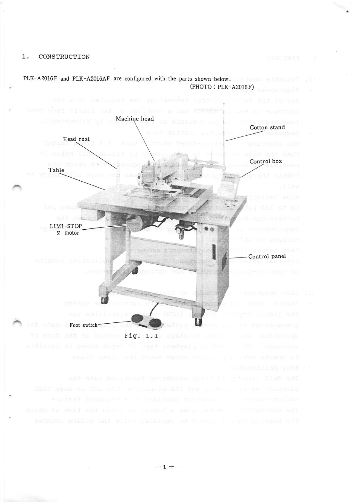
L.
CONSTRUCTION
PLK-A2016F
Table
LIMl-STOP
and
PLK-A2016AF
Head
Z
motor
rest
are
Machine
configured
head
with
the
parts
shown
below.
(PHOTO:PLK-A2016F)
Cotton
Control
stand
box
Foot
switch"
Fig.
1.1
Page 6
2.
(1)
•
FEATURES
Valuable
High-speed
Use
of
contribution
sewing
the
latest
control
to
increasing
technology
productivity
has
resulted
in
a 50%
increase
(compared
Adoption
The
adoption
than
the
possible
bobbin
well.
Wide
Up
pattern
to
thread
variety
150
requirements
numbers
Easy
External
or
adaptability
special-purpose
in
with
of
size
to
patterns
can
of
stitches.
interface
sewing
the
large-sized
of
a
large-sized
featured
drastically
is
replaced
of
needles
be
stored
of
fancy
to
speeds
and
performance
shuttle
in
past
reduce
and
and
featuring
on
a
single
stitching
automatic
functions
machine
are
a
doubling
of
hook
shuttle
models
the
it
patterns
the
or
machine
for
optionally
past
hook
by
frequency
enhances
data
for
floppy
embroidery
use
as
of
the
models
(1.8
Mitsubishi)
the
8,000
disk
an
application
provided.
fabric
by
Mitsubishi).
times
with
work
stitches
to
meet
involving
larger
makes
which
efficiency
the
feed
it
the
per
large
machine
rate
as
^
(2)
Less
Simple
The
liquid
preparation
operation,
messages.
to
create
Easy
The
full
pinpointing
Adding/subtracting
The
subtracting
the
bobbing
dependency
input
crystal
of
and
The
sewing
maintenance
line-up
and
the
it
teaching
of
trouble
thread
on
skills
operation
display
sewing
also
patterns
of
troubleshooting
counters
counter
should
or
thanks
(LCD)
patterns
displays
playback
which
and
its
uses
be
training
vastly
operating
match
display
provided
a
buzzer
replaced
to
and
type
required
interactive
simplifies
the
of
input
the
functions
on
as
a
to
sound
while
system
preparations
errors
clamp
the
standard
the
makes
frame.
make
LCD
the
adding
in
an
the
the
it
the
easy
feature
time
made
form
possible
task.
at
which
counter
for
of
^
— 2 —
Page 7
makes
(3)
Esthetically
it
possible
pleasing
to
verify
seams
the
and
output.
stitching
^ •
Stable
The
uses
feed
fabric
races
intermittent
and
stitches.
Resolution
By
bringing
accurately
both
Maximum
The
where
smoothly
variable
a
large-pitch
system
feed
and
in
the
down
stitch
delicate
sewing
mechanism
backlash-free
feed
0.1
resolution
to
and
length
drive
mm
a
precisely.
stitch
touch
of
units
0.1
of
length
is
such
features
timing
and
makes
of
the
mm
pitch,
12.7
mm
accommodates
required
articles
both
belts.
for
fabric
it
such
as
a
travel
clear,
feed
is
now
everything
as
container
system
It
enables
well-defined
mechanism
possible
in
embroidery
bags.
from
which
reliable
to
sew
stitches
to
seams
— 3 —
Page 8
3.
SPECIFICATIONS
3.1
(1)
General
specifications
Specifications
Type
Needle
Take-up
Needle:
Wiper:
Work
Presser
Presser
Hook:
Bobbin
of
stitching:
bar
lever
Lengthwise
(with
holder
foot
foot
Large-sized
case:
Bobbin:
Thread
trimmer:
of
stroke:
stroke:
DP x
17
wiper
lift:
lift:
stroke:
With
Aluminum
mechanisms
Single-needle
41.2
68
#18
(standard)
thread
release
25
mm
10
mm
4
shipped)
shuttle
slip
bobbin
Combination
mm
mm
wiping
switch)
or
higher
to
10
mm
hook
prevention
for
large-sized
of
lockstitch
drive
(set
spring
fixed
to
knife
4
mm
hook
and
^
when
movable
Lubrication
Oil
used:
Sewing
Max.
Stitch
area:
sewing
length:
Dimensions:
Weight:
White
ISO
knife
system:
spindle
(plane
Manual
with
oil
oiling
oil
scissoring)
braid
No.2
and
replenishment
(Tank
type)
PLK-A2016F *200mm in X (cross-wise) direction
160mm in Y (lateral)
PLK-A2016FL 250mm in X (cross-wise) direction
speed:
0.1
2,000
than
to
12.7
190mm in Y
spm
3.0
mm)
mm
(for
(lateral)
feed
direction
direction
length
PLK-A2016F:1200(W)X1260(L)X1120(H)mm
PLK-A2016FL:1200
(Excluding
kgf
(total
(W)X1275
cotton
weight
(L)X1120(H)
stand)
including
mm
head,
of
table)
less
— 4 —
Page 9
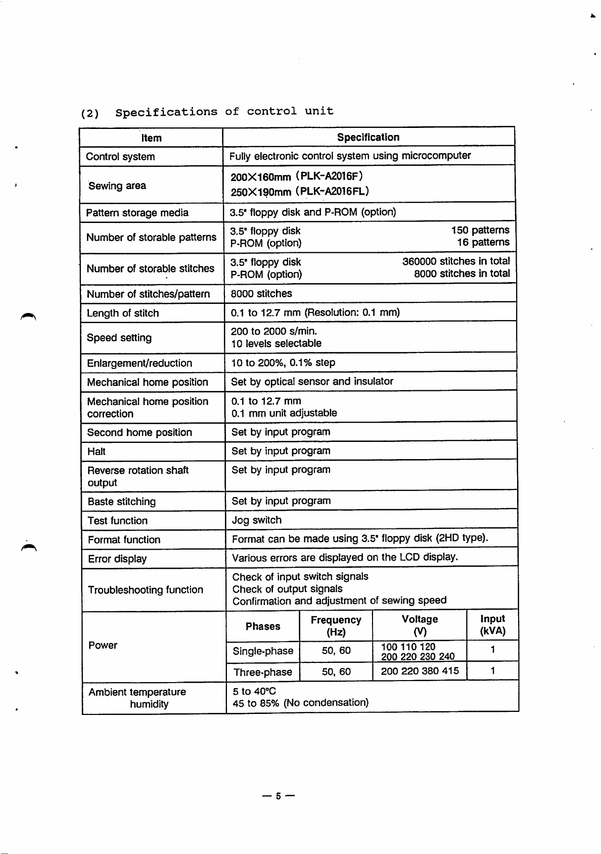
(2)
Specifications
of
control
unit
Item
Control
Sewing
Pattern
Numberofstorable
Number
system
area
storage
of
storable
media
patterns
stitches
Numberofstitches/pattern
Length of stitch
Speed
setting
Enlargement/reduction
Mechanical home position
Mechanical
correction
home
position
Specification
Fullyelectronic control system using microcomputer
200X160mm (PLK-A2016F)
250X190mm
3.5*
floppy disk
3.5" floppy disk
P-ROM
3.5"
floppy
P-ROM
8000
stitches
(PLK-A2016FL)
and
P-ROM
(option)
150
(option) 16 patterns
disk 360000 stitches in total
(option) 8000 stitches in total
0.1 to 12.7 mm (Resolution: 0.1 mm)
200to2000
10
levels
10to200%,
Set
by optical
0.1to12.7
0.1 mm unit
s/min.
selectable
0.1%
sensor
mm
adjustable
step
and
insulator
patterns
Second
Halt
Reverse
output
Baste
Test
Format
home
rotation
stitching
function
function
Error display
Troubleshooting
Power
Ambient
temperature
humidity
position
shaft
function
Set
by input
Setbyinput
Set
by input
Setbyinput
Jog
switch
program
program
program
program
Format can be made using 3.5"floppy disk
Various errors
Check
of input switch
Checkofoutput
Confirmation
Phases
Single-phase
Three-phase
5to40°C
are
displayed on
signals
signals
and
adjustment of sewing
Frequency
(Hz)
50.
60
50,
60
the
LCDdisplay.
Voltage
100 110
200 220
200
220
speed
(V)
120
230
45 to 85% (No condensation)
380
(2HD
240
415
type).
Input
(kVA)
1
1
— 5 —
Page 10
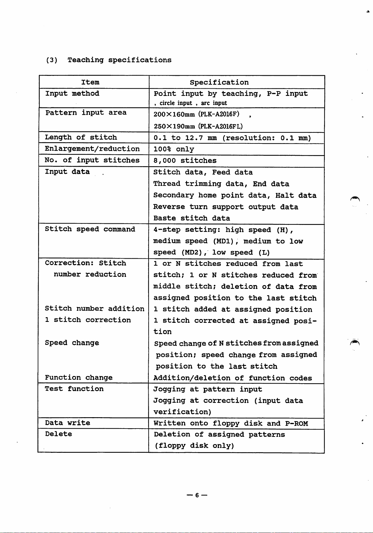
(3)
Teaching
specifications
Item
Input
Pattern
Length
method
input
of
stitch
Enlargement/reduction
No.
of
Input
Stitch
Correction:
number
input
data
speed
stitches
command
Stitch
reduction
area
Point
,
circle
input
input*arc
200X160niin
250X190min
0.1
to
12.7
100%
8,000
Stitch
Thread
only
stitches
data.
trimming
Secondary
Reverse
Baste
4-step
medium
speed
1
stitch;
or
stitch
setting:
speed
(MD2),
N
stitches
Specification
by
teaching,
input
(PLK-A2016F) ,
(PLK-A2016FL)
mm
(resolution:
Feed
data.
home
turn
point
support
data
high
(MDl),
low
reduced
1
or
N
stitches
data
speed
End
data.
output
speed
medium
(L)
from
reduced
P-P
data
0.1
Halt
data
(H),
to
input
mm)
data
low
last
from
Stitch
1
stitch
Speed
Function
Test
Data
Delete
number
change
function
write
correction
change
addition
middle
assigned
1
stitch
1
stitch
tion
Speed
position;
position
stitch;
position
added
corrected
change
speed
to
Addition/deletion
Jogging
Jogging
at
at
verification)
Written
Deletion
(floppy
onto
of
disk
deletion
to
at
assigned
ofNstitches
change
the
last
of
pattern
correction
floppy
assigned
only)
the
at
stitch
function
input
disk
patterns
of
data
last
position
assigned
from
from
(input
and
from
stitch
posi
assigned
assigned
codes
data
P-ROM
— 6 —
Page 11
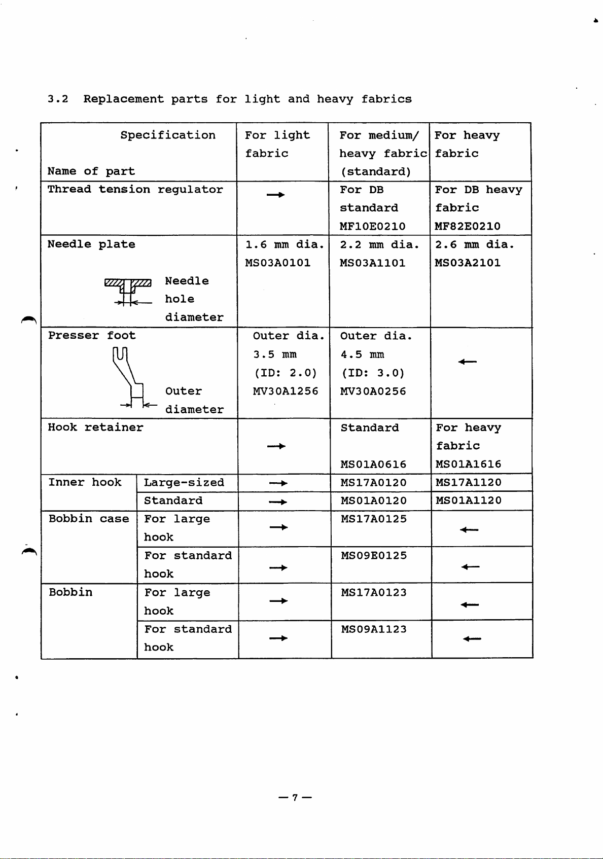
3.2
Replacement
parts
for
light
and
heavy
fabrics
Name
Thread
Needle
Presser
Hook
of
tension
plate
retainer
Specification
part
foot
regulator
Needle
hole
diameter
Outer
diameter
For
light
fabric
1.6
mm
MS03A0101
Outer
3.5
(ID:
MV30A1256
mm
dia
dia,
2.0)
For
medium/
heavy
(standard)
For
DB
standard
MF10E0210
2.2
mm
MS03A1101
Outer
4.5
mm
(ID:
MV30A0256
Standard
fabric
dia
3.0)
dia
For
heavy
fabric
For
DB
fabric
MF82E0210
2.6
mm
MS03A2101
For
heavy
heavy
dia.
Inner
Bobbin
Bobbin
hook
case
Large-sized
Standard
For
large
hook
For
standard
hook
For
large
hook
For
standard
hook
MS01A0616
MS17A0120
MS01A0120
MS17A0125
MS09E0125
MS17A0123
MS09A1123
fabric
MS01A1616
MS17A1120
MS01A1120
— 7 —
Page 12
4.
INSTALLATION
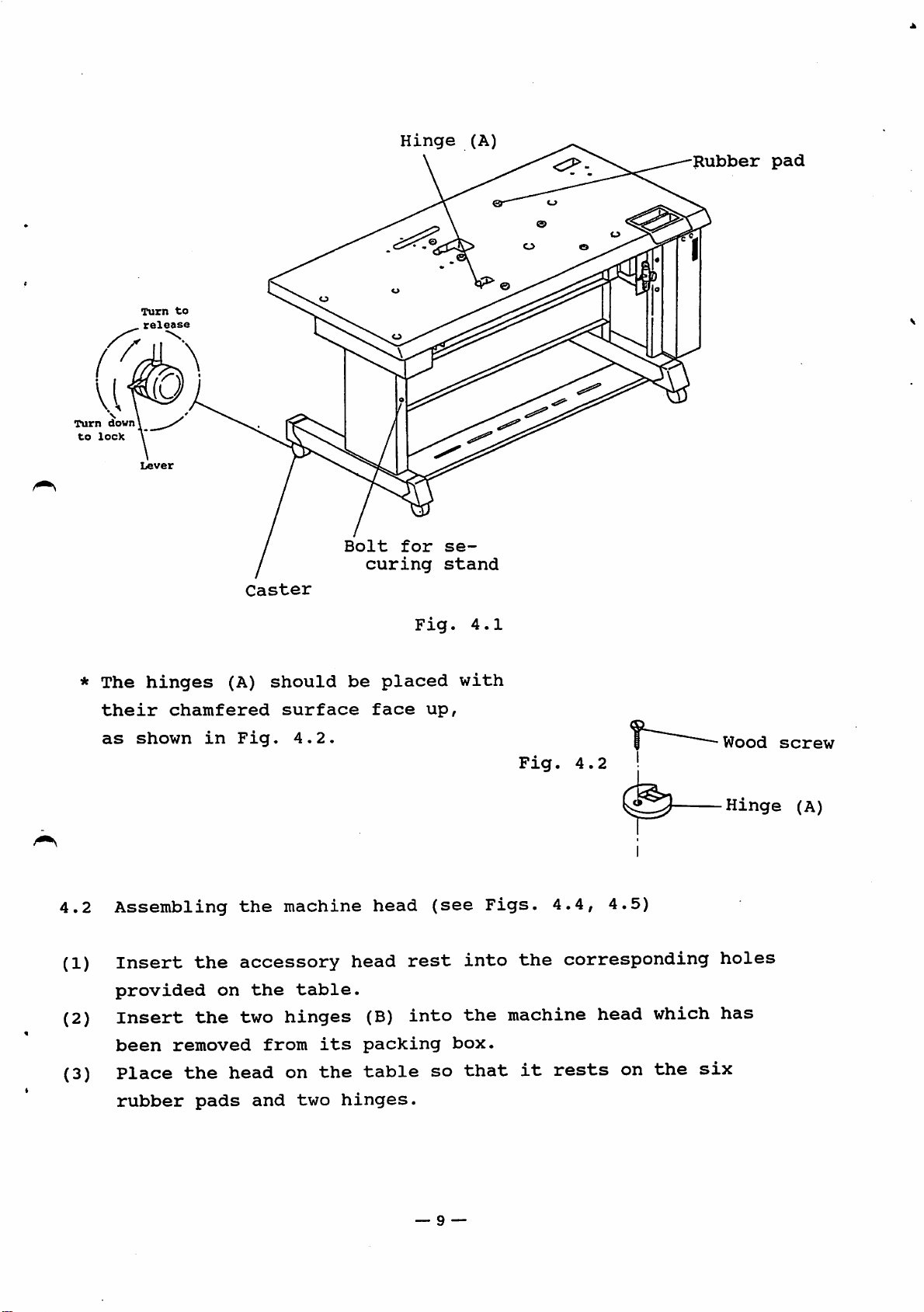
4.1
Installing
(1) The
pressing
machine
them.
(2)
Install
it
(3) The
standing
adjusted for
follows
(I)
Loosen
d)
Lift
stand.
Notes:
casters
does
table
the
the
tabletothe
the
under
down
is
the
not
or
to
sewing
tilt
can
sitting
on
be
be
sitting
to
operate
bolts(5units
desired
table
the
the
moved,
or
set
at the left
height
table
lever
raise
machine
wobble.
for
position.
work,
the
machine
and5units
and
can
of
each
the
on a
operating
Since
change
in
at the
then
secureitproperly
be
flat
locked
caster.
caster
and
the
it
the
a
standing
right)
into
When
levers
rigid
sewing
has
been
table
height as ^
usedtosecure
using
position
the
to
floor
machine
factory-
position.
the stand,
the
bolts
sewing
release
so
for
securing
in
by
that
a
the
® The
(D
(4)
(5)
is
installed.
If
the
has
(for
Insert
holes
Insert
in
the
screws.
table
been
safety)
provided
height
table
installed,
an
accessory
the
table
should
height
and
then
in
the
accessory
and
secure
be
must
detach
proceed.
rubber
table.
hinges
them
changed
be
changed
the
pad
(A)
head
(6
with
units)
(2
the
before
after
from
units)
countersunk
the
the
above
into
into
machine
machine
the
table
each
the
of
recesses
wood
head
head
the
— 8 —
Page 13
Turn
to
lock
down
Turn
Hinge
to
(A)
Rubber
pad
4.2
(1)
*
The
their
as
Assembling
Insert
provided
hinges
chamfered
shown
(A)
in
the
on
Caster
should
surface
Fig.
the
4.2.
machine
accessory
the
table.
Bolt
curing
be
head
for
placed
face
head
Fig.
up,
rest
se
stand
(see
4.1
with
into
Figs.
Fig.
4.2
4.4,
the
corresponding
4.5)
Wood
Hinge
holes
screw
(A)
(2)
(3)
Insert
been
Place
rubber
the
removed
the
pads
two
head
and
hinges
from
on
two
its
the
hinges.
(B)
into
packing
table
so
— 9 —
the
box.
that
machine
it
rests
head
on
which
the
has
six
Page 14
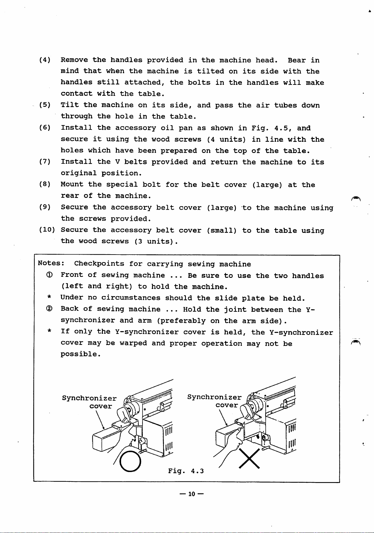
(4)
Remove
the
handles
provided
in
the
machine
head.
Bear
in
(5)
(6)
(7)
(8)
(9)
(10)
mind
handles
contact
Tilt
through
Install
secure
holes
Install
original
Mount
rear
Secure
the
screws
Secure
the
wood
that
the
it
which
the
of
the
the
when
still
with
machine
the
the
using
the
position.
special
the
accessory
provided.
accessory
screws
the
attached,
the
table.
on
hole
in
accessory
the
have
V
machine.
been
belts
(3
machine
its
the
wood
provided
bolt
belt
belt
units).
the
side,
table.
oil
pan
screws
prepared
for
the
cover
cover
is
bolts
tilted
and
as
and
shown
(4
on
return
belt
(large)
(small)
in
pass
units)
the
on
the
top
cover
its
the
in
the
to
to
side
handles
air
Fig.
in
line
of
the
machine
(large)
the
the
with
will
tubes
4.5,
and
with
table.
to
at
machine
table
the
make
down
the
its
the
using
using
Notes;
(D
*
(D
Checkpoints
Front
(left
Under
Back
of
of
and
no
sewing
synchronizer
If
only
cover
possible.
Synchronizer
the
may
cover
for
sewing
right)
machine
to
circumstances
machine
and
arm
Y-synchronizer
be
warped
carrying
...
hold
should
...
(preferably
and
proper
sewing
Be
the
machine.
Hold
cover
Synchronizer
sure
the
slide
the
on
is
operation
cover
machine
to
use
joint
the
held,
plate
between
arm
the
may
the
two
be
held.
the
side).
Y-synchronizer
not
be
handles
Y-
Fig.
4.3
—
10
—
X
Page 15
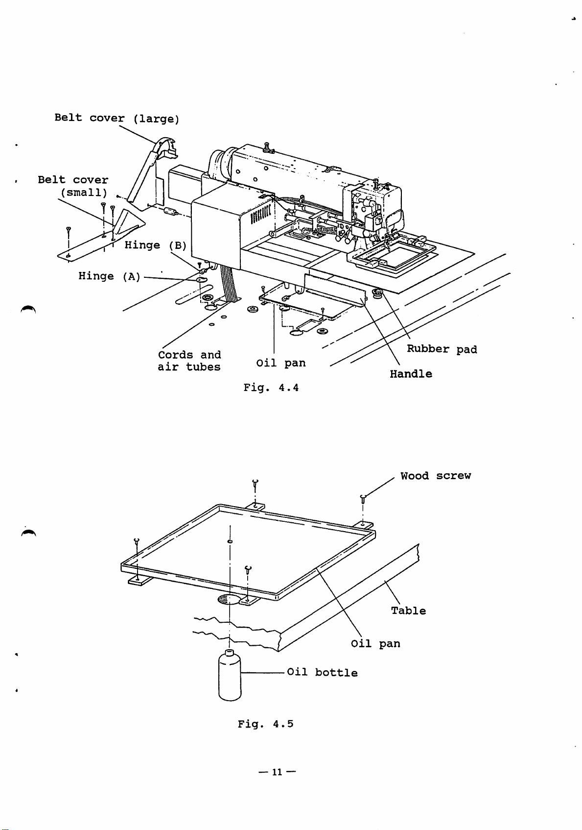
Belt
cover
(large)
Belt
cover
(small)
Hinge
Hinge
(A)
(B)
Cords
air
tubes
and
pi
Fig.
Oil
pan
4.4
Rubber
Handle
pad
Fig.
4.5
Oil
bottle
Oil
pan
Wood
Table
screw
—
11
—
Page 16
4.3
(1)
(2)
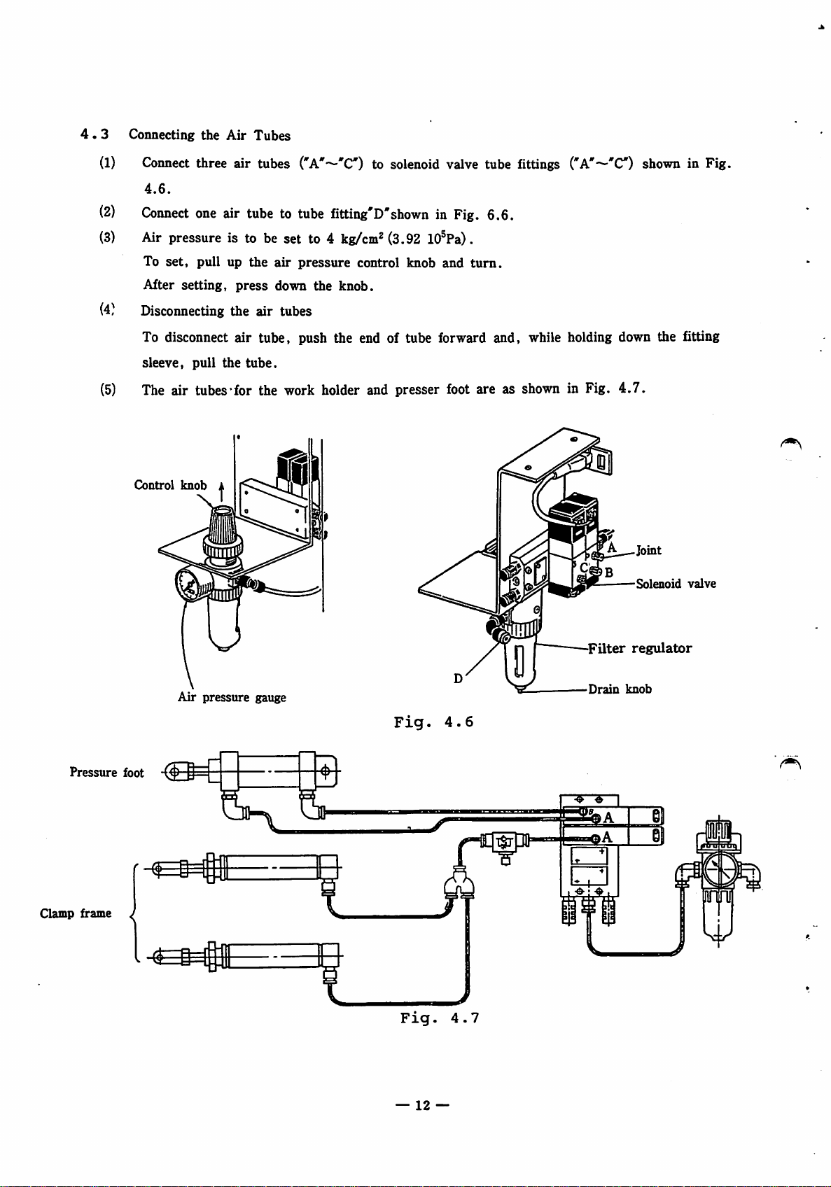
Connecting
Connect
4.6.
Connect
the
Air
Tubes
three air tubes
one
air
tubetotube
('A'—'C)
to solenoid valve tube fittings
fitting'D'shown in Fig. 6.6.
("A'-^'C)
shown in Fig.
(3)
Air pressure is to be set to 4
To
set,
pull up
After
(4)
setting,
Disconnecting
To disconnect
sleeve,
pull
press
the air tubes
air
the
the
air
down
pressure
the
kg/cm^
knob.
(3.92 lO^Pa).
control knob and
turn.
tube, push the end of tube forward and, while holding down the fitting
tube.
(5) The air tubes'for the work holder and presser foot are as shown in Fig.
Control
knob
4.7.
Joint
Solenoid
valve
Pressure
Clamp frame ^
foot
Air
pressure
gauge
Fig.
Fig.
4.6
4.7
T$T
Filter
Drain
regulator
knob
II
—
12
—
Page 17
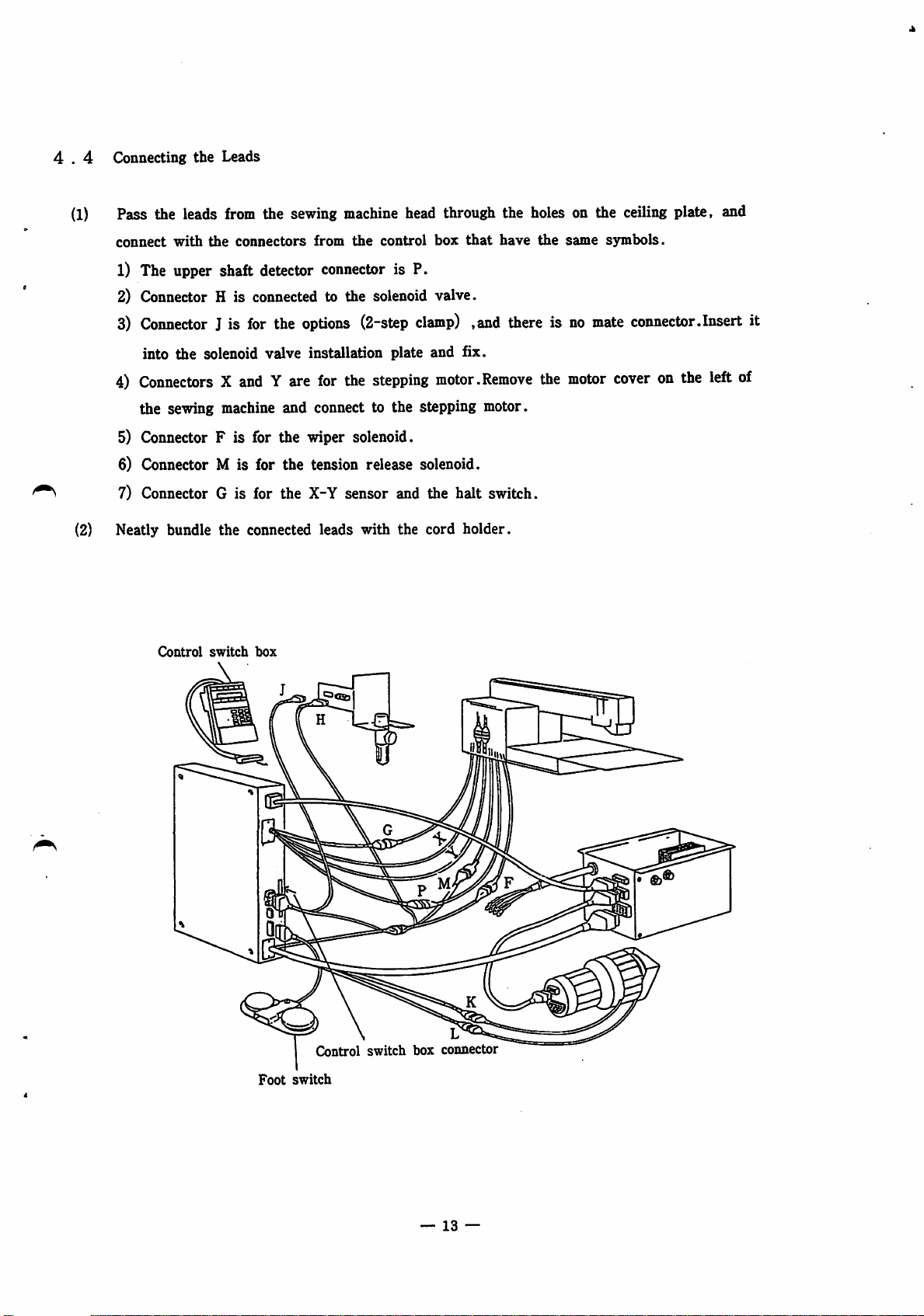
4 . 4 Connecting
(1)
Pass the leads
the
Leads
from
the sewing
machine
head through the holes on the
ceiling
plate, and
connect
with
the
connectors
from
the
control
box
that
have
1) The upper shaft detector connector is P.
2) Connector H is connected to the solenoid valve.
3)
Connector
into
4)
ConnectorsXand
the sewing machine and connect to the stepping motor.
5) Connector F is for the wiper solenoid.
6) Connector M is for the tension release solenoid.
^ 7) Connector G is for the X-Y sensor and the halt switch.
(2) Neatly bundle
Control
J is
for
the
options
the
solenoid valve installation plate and fix.
Y are
the
connected leads with the
switch
box
for
(2-step
the
clamp)
stepping
,and there isnomate
motor.Remove
cord
holder.
the
the
same
motor
symbols.
connector.Insert it
cover
on the
left
of
Foot
Control
switch
switch
box
—
connector
13
—
Page 18
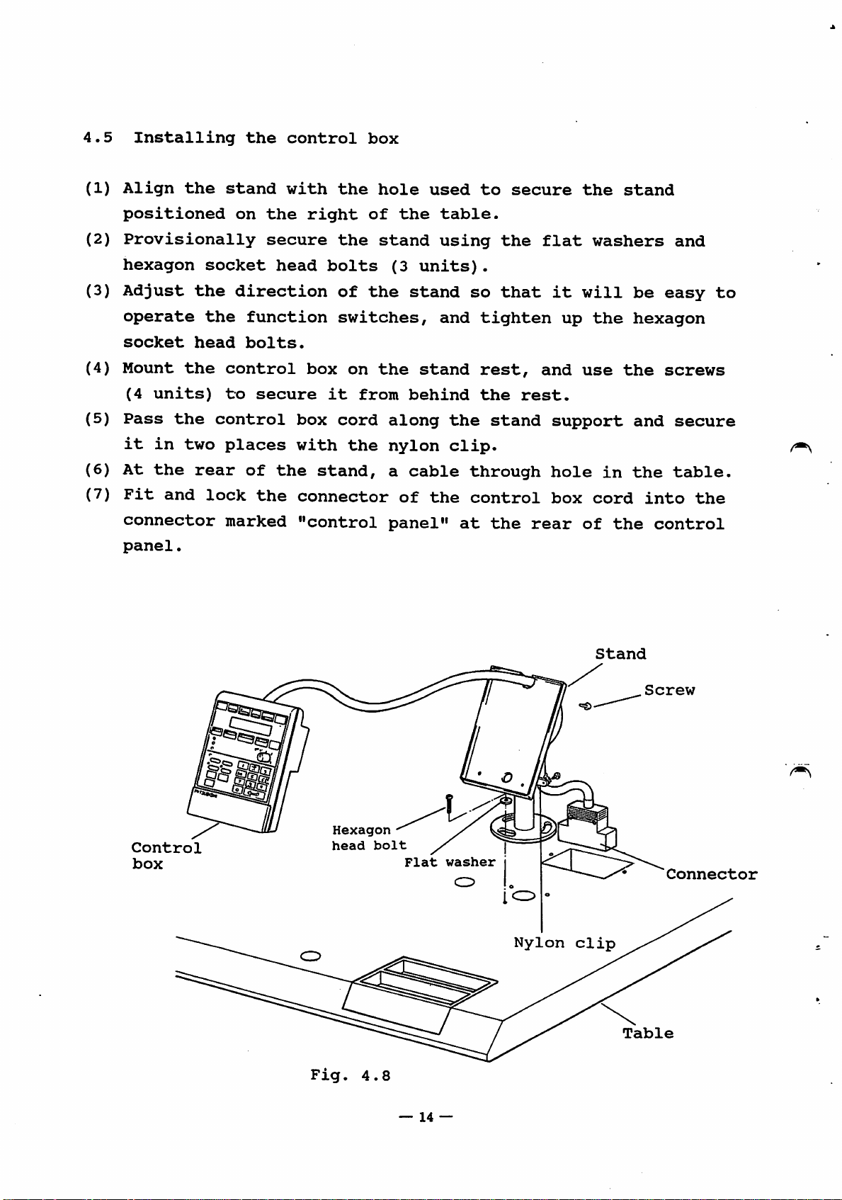
4.5
(1)
Installing
Align
the
the
stand
control
with
the
box
hole
used
to
secure
the
stand
positioned
(2)
Provisionally
hexagon
(3)
Adjust
operate
socket
(4)
Mount
(4
(5)
Pass
it
(6)
At
(7)
Fit
connector
panel.
units)
the
in
the
and
the
head
the
two
rear
on
socket
direction
the
control
to
control
places
lock
marked
the
secure
head
function
bolts.
secure
of
the
the
right
the
bolts
of
switches,
box
on
it
box
cord
with
the
stand,
connector
"control
of
stand
the
the
from
the
(3
units).
stand
stand
behind
along
nylon
a
cable
of
panel"
table.
using
and
the
clip.
the
so
tighten
rest,
the
stand
through
control
at
the
the
that
rest.
rear
flat
it
up
and
support
hole
box
washers
will
the
use
the
in
cord
of
the
and
be
easy
hexagon
screws
and
secure
the
table.
into
control
to
the
Control
box
head
bolt
Flat
washer
Nylon
Stand
Connector
clip
Fig.
4.8
—
14
—
Page 19
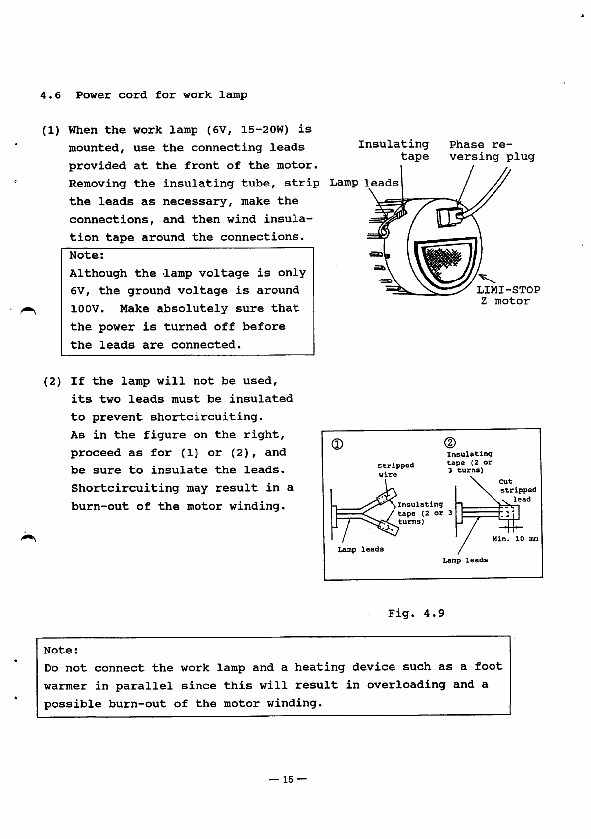
4.6
(1)
Power
When
the
mounted,
provided
cord
work
use
at
for
the
lamp
the
work
(6V,
connecting
front
lamp
of
15-20W)
leads
the
motor.
is
Insulating
tape
Phase
versing
re
plug
Removing
the
connections,
tion
Note:
Although
6V,
10OV.
the
the
(2)
If
its
to
As
proceed
be
Shortcircuiting
burn-out
leads
tape
the
Make
power
leads
the
two
prevent
in
the
sure
the
as
around
the
ground
absolutely
is
are
lamp
will
leads
shortcircuiting.
figure
as
for
to
insulate
of
the
insulating
necessary,
and
then
the
lamp
voltage
voltage
turned
connected.
not
must
on
(1)
may
motor
tube,
make
wind
connections.
is
sure
off
before
be
used,
be
insulated
the
right,
or
(2),
the
leads.
result
winding.
the
insula
is
only
around
that
and
in
strip
a
Lamp
leads
stripped
wire
Insulating
tape
turns)
LIMI-STOP
Z
motor
Insulating
tape
(2
3
(2
or
or
turns)
cut
stripped
lead
Note:
Do
not
warmer
possible
connect
in
parallel
burn-out
the
work
since
of
the
lamp
this
motor
and
will
winding.
—
a
heating
result
15
—
Lamp
in
leads
device
Fig.
such
overloading
4.9
Lamp
as
a
and
leads
foot
a
Min.
10
mm
Page 20

4.7
Use
Connecting
a
power
supply
the
power
with
cable
a
capacity
high
enough
to
accommodate
the
motor
adequate
(1)
When a
correct
white
(2)
Connect
ground
undertake
qualified
This
supply
3
(3)
When a
into
Notes:
rating,
to
grounding
pins
a
and
accommodate
3-phase
phase
lead;
the
terminal.
"W"
green
this
electrician
and
the
with
ground
single-phase
branch
select
motor
sequence:
phase
lead
To
ground
work
accessory
to
socket
a
power
the
power
is
used,
"U"
...
in
ensure
connection.
do
must
2
pins)
motor
but
cable
supply
connect
phase
black
the
3-phase
safety,
this
be
conversion
to
is
for
done
are
used,
a
wall
...
lead.
you.
if
used.
which
is
requirements.
the
red
power
do
not
Be
sure
a
single-phase
plug
do
outlet.
(for
not
more
power
lead;
cable
neglect
to
plug
than
supply
"V"
phase
to
to
have
a
power
conversion
the
power
the
in
its
...
^
from
cord
All
will
<2>
The
<3>
The
connected.
4.8
If
Changing
the
motor
direction,
when
machine
operation
leads
not
plugs
power
reverse
stops
should
come
and
into
connectors
plug
the
direction
of
the
is
started,
operating.
be
bundled
contact
must
be
sewing
rotation
REVERSE
together
with
must
be
disconnected
of
the
motor
machine
is
the
is
first
following
ROTATION
and
the
V-belts.
securely
when
rotation
rotating
identified
display
secured
so
connected.
any
of
the
in
the
automatically
appears,
that
leads
reverse
and
they
are
the
—
16
—
Page 21

When
this
display
has
appeared,
normal
rotation
is
restored
by
turning
Be
sure
4.10)
Since
it
completely
switch
motor
while
rotation
the
on
the
phase-reversing
to
insert
takes
about
after
the
power
will
motor
it
the
is
properly
5
minutes
power
after
remain
running.)
plug
as
for
has
been
it
has
unchanged
through
far
as
a
single-phase
turned
stopped.
if
180°
it
the
will
off,
(The
power
and
go.
remember
direction
inserting
(See
motor
is
turned
Direction
of
Fig.
to
to
of
rotation
it.
stop
the
on
Note:
Phase-
reversing
Be
sure
disconnecting
to
plug
set
the
the
power
power
Fig.
switch
plug.
—
17
—
4.10
to
the
OFF
position
when
Page 22

5.
(1)
(2)
PREPARING
Check
of
Check
that
the
that
TO
sewing
OPERATE
the
the
supply
machine
floppy
AND
voltage
being
disk
PRECAUTIONS
conforms
used.
containing
with
the
the
patterns
requirements
has
been
(3)
(4)
•
•
(5)
installed
(When
the
patterns
inside
Check
Section
Check
Move
is
Make
foot.
Position
The
such
that
out
and
always
sure
relationship
that
holder
equivalent
Fig.
5.1.
are
the
7.1.)
position
of
but
properly.
sewing
contained
front
the
machine
the
following
located
that
the
the
work
home
deviates
to
the
machine
cover
the
work
within
needle
holder
between
position
to
allowance
leaves
on
of
parts
points
the
the
the
the
the
holder
is
is
right
for
the
accessory
control
have
before
frame
set
at
work
not
of
the
manufacturing
floppy
panel.)
been
lubricated.
turning
by
hand
of
the
the
center
holder
at
and
the
center
presser
so
work
center
by
foot,
disk
on
that
holder.
of
home
a
dimension
plant,
attached
(See
the
power.
the
the
position
of
the
as
shown
test
needle
presser
is
work
in
holder
Work
(6)
Check
that
kgf/cm» .
Home
needle
PLK-A2016F
the
air
(S.SEXlo'Pa)
Work
is
holder
Effective
sewing
position
hole
being
position)
Fig.
arm
area
Work
holder
(same
as
5.1
supplied
—
18
—
Work
holder
j"'
Effective
sewing
•
i
Home
163
at
148
PLK-A2016FL
a
pressure
needle
position
hole
of
position)
4
area
(same
arm
as
Page 23

6.
(1)
CHECKPOINTS
Safety
FOR
OPERATION
® A
(D
(2)
<D
© Do
®
machine
must
be
remember
work
Make
order
Operating
Do
40®C)
or
or
absolutely
to
not
or
malfunctioning
not
will
such
Take
from
be
as
care
entering
which
taken
to
turn
inspections.
safeguard
environment
operate
low
temperatures
install
exposed
heating
not
is
not
off
sure
the
the
to
appliance.
to
allow
the
operating
to
touch
the
that
against
sewing
may
occur
sewing
direct
machine
power
water
is
any
of
before
the
sewing
noise
machine
(under
in
machine
sunlight
or
head
dangerous
its
and
at
S'C).
the
machine.
in
or
any
other
and
control
and
moving
proceeding
machine
electric
high
temperatures
Otherwise,
a
position
near
liquid
a
unit
so
parts.
is
grounded
shocks.
source
every
with
trouble
where
of
substance
and
to
care
Also,
repair
in
(over
it
heat
keep
(3)
®
(D
(D
(D
(D
metal
sewing
The
sewing
will
be
Avoid
be
exposed
Operation
Do
NOT
the
floppy
drive
lost.
Turn
cassette.
When
off
sewing
perform
waste
machine.
exposed
using
turn
LED
the
a
and
machine
the
to
off
disk
is
lighted).
power
a
test
other
cannot
explosive
sewing
excessive
the
drive
before
new
pattern
operation
conductive
machine
shock
power
is
This
be
used
gases,
or
remove
reading
may
inserting
or
enlarging
and
check
materials
in
or
in
an
dust
a
location
or
vibration.
the
or
writing
cause
or
the
away
atmosphere
oily
vapors.
where
floppy
data
the
data
removing
a
pattern,
relationship
from
disk
stored
the
the
where
it
while
(while
P-ROM
be
between
will
sure
to
it
the
be
to
the
work
holder
and
pattern.
—
19
—
Page 24

®
Remove
your
foot
from
the
start
switch
(pedal
switch)
when
turning
<D
The
turned
that
When
bobbin
®
The
length.
accordance
should
the
presser
manually.
the
the
winder
maximum
be
Stitch
Stitch
0.1
3.1
3.6
4.1
power
foot
wheel
power
sewing
The
with
set
length
to
to
to
to
switch
must
It
can
be
is
ON,
switch
speed
maximum
the
for
each
length
(mm)
3.0
3.5
4.0
4.5
be
is
lowered
rotated
it
to
the
speed
lengths
individual
and
ON
or
lowered
can
be
ON
differs
is
shown
maximum
Maximum
OFF.
when
when
without
the
the
further
lowered
position.
according
automatically
in
the
fabric.
speed
speed
2,000
1,820
1,670
1,430
balance
power
by
table,
limit
limit
adjustment.
setting
to
the
limited
(spm)
is
and
wheel
off
the
stitch
in
it
is
so
(2)
When
®
Burnouts
mechanical
®
Under
fingers
being
start
the
power
stabilizes.
(see
4.6
5.1
6.6
9.1
a
single-phase
operation
has
may
page
24)
no
circumstances
near
operated.
to
to
to
to
—
—
be
parts.
the
5.0
6.5
9.0
12.7
immediately
been
caused
Before
and
check
work
motor
switched
by
the
should
holder
is
being
but
wait
on
until
insufficient
operation,
parts.
the
while
1,250
1,000
800
600
400
200
used,
about
the
be
operator
the
do
not
10
motor
lubrication
sure
to
bring
sewing
perform
seconds
operation
lubricate
his
machine
of
the
or
the
after
her
is
® Do
not
protective
operate
covers
the
sewing-
in
place.
machine
—
20
—
without
the
eye
guard
and
Page 25

(4)
(D
(D
Supply
Use
When
voltage
a
supply
an
instantaneous
voltage
within
power
a
±10%
failure
range
occurs,
of
the
the
rating.
sewing
(5)
machine
operation,
switch
Noise
(D
When
the
the
(D
Similar
operated
high
the
use
(D
Using
noise
broadcast.
or
it
the
stitch
sewing
noise
machine
a
separate
a
interference
place
stops
first
back
power
pattern
machine.
effects
in
levels
radio
the
in
the
as
or
In
radio
the
make
on
again.
line
may
vicinity
(such
far
power
TV
cases
reset
is
may
occur
away
line
set
in
like
or
sure
affected
shift
when
of
as
from
to
near
the
reception
this,
TV
set
or
error
that
a
the
by
surge
or
malfunctioning
the
sewing
any
equipment
high-frequency
such
equipment
supply
the
sewing
use
at
a
distance
mode.
power
power
of
the
a
different
To
is
OFF
voltages
machine
which
welder).
is
to
it.
machine
radio
from
resume
and
may
generates
possible
may
or
power
the
then
(noise),
occur
is
Keep
cause
TV
supply
sewing
in
and
(6)
(7)
machine.
Inspection
(D
Avoid
circuitry
semiconductor
Up-turn
When
of
0
Before
(upper,
to
(D
Remove
sewing
of
using
of
the
thread
turning
see
prevent
beforehand.the
machine
head
as
of
control
a
multimeter
since
sewing
the
parts.
circuitry
voltage
machine
to
head
sewing machine head
trimmer,
Fig.
it
sliding
it
is
up
the
7.1)
motor
raised
etc.,
because
head
with
down
V
belt
higher.
observe
inspect
from
is
(see
the
with
which
the
the
such
turned
following
Fig.
adhesive
its
own
is
belt
internal
may
damage
up
for
6.2),
tape,
weight.
connected
will
control
the
the
cautions.
fix
X-Y
etc.
to
disturb
adjustm.ent
cover
in
order
7
type
the
up—turn
—
21
—
Page 26

(D
Place
a
holder
of
head
on
the
table
(Fig.
6.1).
Since
the
belt
7.
Names
cover
remove
Belt
(large)
HANDLING
of
(small)
beforehand
cover
V
THE
major
Belt
belt
SEWING
parts
interferes
the
cover(small)
/
Head
of
cover
holder
MACHINE
machine
with
by
HEAD
head
the
loosing
head
Up-turn
of
head
when
set
it
screws.
Fig.
is
raised,
6.2
Belt
cover
(small)
Eye
Slide
plate
Halt
guard
Needle
Presser
adjusting
switch
plate
foot
Work
holder
screw
Thread
Clamp
unit
regulator
viium
Feed
plate
tension
X-Y
Bobbin
winder
cover
(top)
X-Y
cover(bottom)
Synchronizer
Y-synchronizer
cover
Oil
gauge
Fig.
—
7.1
22
—
Page 27

7.1
(1)
Lubrication
Supplying
the
lubricant
Before
necessary,
proceeding
parts
J I
with
A
to
operation,
F
indicated
be
by
sure
the
to
arrows
lubricate,
in
Fig.
as
7.2.
Lubricate
after
(Normally,
supply
(2)
Replenishing
Replenish
and
red
may
tilted.
the
tank.)
head
mark
cause
parts
sewing
lubricant
the
oil
side,
in
the
oil
A
to
J
machine
is
oil
tank
through
respectively,
center
to
spill
Fig.
before
has
supplied
supply
of
the
from
7.2
proceeding
been
automatically
ports
until
oil
the
supply
installed.
K
and
the
oil
gauge.
ports
with
L
on
reaches
Excessive
when
a
test
(Fig.
from
the
arm
the
the
run
7.2)
the
side
round
supply
head
oil
is
—
23
—
Page 28

Note;
Oil
Use
tank
white
spindle
oil
#2
for
Oil
lubrication.
tank
7.2
(1)
(2)
(3.)
(4)
Installing
Before
so
that
Insert
go.
With
the
For
that
the
needle
more
the
direction
the
installing
the
sewing
the
needle
needle
set
satisfactory
needle
of
^ D
the
needle
prime
screw
be
arrow
S-
Fig.
or
removing
machine
into
to
installed
2=3
7.3
the
groove
secure
stitching
in
Fig.
the
will
needle
turned
and
M=r
needle,
not
socket
the
results,
turned
7.4
be
to
needle.
Clearance
turn
started
as
the
it
by
off
up
far
front,
is
recommended
about
in
as
tighten
10°
the
it
power
error.
will
in
up
the
o
V
Fig.
—
X X
7.4
24
—
I)
Page 29

7.3
The
Threading
needle
thread
the
needle
should
thread
be
threaded,
as
shown
in
Figs.
7.5
and
7.6,
7.4
(1)
with
Winding
Pass
Fig.
the
the
7.7
thread
the
thread
and
bobbin
coming
wind
end
the
extended
thread
from
end
of
the
the
about
spool
4
thread
cm
Arm
holder
from
thread
guide
around
Fig.
base
the
Top
the
needle.
Thread
thread
7.6
as
bobbin
Take-up
spring
Tension
discs
shown
guide
in
by
several
turns
in
the
direction
Fig.
of
arrow
7.7
"a."
—
25
—
Page 30

(2)
(3)
Push
Lower
the
the
adjust
work
lever
holder
in
using
the
direction
the
work
of
holder
arrow
switch
(b).
(black
(4)
(5)
(6)
7.5
(1)
(2)
pedal
Setting
ON
position
the
sewing
Step
While
will
Upon
winder
Installing
Place
the
bobbin
Put
the
slit
the
eyelet
switch).
the
machine
on
the
the
start
operate
completion
key
again.
the
bobbin
case
thread
(C)
and
(D).
bobbin
(LED
start
at
the
(E)
pass
winder
lights)
to
switch
switch
a
speed
of
the
(This
bobbin
(B)
(A).
into
it
lowers
enter
(red
is
equivalent
thread
turns
inside
the
through
switch
the
pedal
pressed
winding,
on
the
bobbin
the
the
presser
winder
switch).
down,
to
approximately
press
LED
off.)
control
the
panel
foot
mode.
sewing
the
and
machine
600
bobbin
to
allows
spm.
the
7.6
(1)
(2)
(See
Installing
Set
the
position
(See
Open
fully
the
inner
Note;
The
thread
about
in
the
Fig.
Fig.
the
and
2.5
7.8)
needle
and
7.9)
bobbin
hook.
bobbin
fit
cm
end
the
open
from
bar
it
should
case.
bobbin
to
the
case
securely
the
case
its
bottom
latch
be
square
highest
cover
(A)
into
extended
hole
Fig.
Fig.
7.8
7.9
—
26
—
Page 31

7.7
Removing
the
inner
hook
The hook clamp and
the
hook
arrow
7.8
Attain
as
Thread
a
clamp
far
as
tension
balance
lever
the
inner
(Fig.
horizontal
between
hook
7.10)
the
itself
in
position.
Fig.
needle
can
the
Hook
7.10
thread
be
removed by
direction
clamp
tension
shown by
lever
and
turning
the
bobbin
thread
As shown
the
needle
center
®
Balanced
tension
thread
tension.
in
line
Fig.
thread
of
O
needle
and
tension
the
bobbin
(A),
is
thread
the
interlocked
fabric
optimum
layers.
Tight
or
thread
needle
loose
tension
with
X
bobbin
tension
Fig.
the
tension
7.11
balance
bobbin
is
thread
Loose
tension,
bin
yielded
along
needle
tight
thread
tension
when
the
thread
bob
—
27
—
Page 32

(1)
Bobbin
The
thread
bobbin
tension
thread
tension
can
be
adjusted
by
turning
the
thread
turning
counterclockwise.
(2)
Needle
The
bobbin
regulating
tension
thread
needle
thread
Bobbin
the
Tension
adjusting
screw
tension
thread
tension.
thumb
case
adjusting
clockwise
(Fig.
tension
nut
To
increase
To
reduce
in
screw
screw.
7.12)
is
To
Fig.
and
adjusted
adjust,
7.13.
The
reduced
turn
tension
by
in
reference
the
is
turning
tension
increased
it
to
Tension
ting
thumb
To
To
reduce
by
the
regula
nut
increase
Note:
Excessive
7.9
Adjusting
7.9.1
The
work
system,
regulator
higher
The
standard
Fig.
7.12
tension
Adjusting
holder
and
it
knob.
work
holder
air
may
the
work
the
pressure
can
be
(See
pressure
pressure
result
holder
work
is
adjusted
Fig.
in
holder
generated
4.6)
and
is
4
puckering
pressure
by
turning
Increase
reduce
kgf/cm^.
by
it
Fig.
or
a
the
the
for
7.13
a
broken
pneumatic
air
pressure
air
pressure
a
lower
thread.
(air)
pressure.
for
a
—
28
—
Page 33

7.9.2
(1)
(2)
The
To
arm
To
Replacing
work
remove
pin.
install
holder
it,
the
the
work
can
push
the
replacement
holder
be
replaced
work
holder
work
in
a
down
holder,
single-action
from
the
engage
work
its
operation.
holder
U-groove
with
play
of
the
in
play
work
the
may
holder
direction
cause
a
arm
indicated
shift
pin.
in
the
Then
by
stitches.
check
the
that
arrow.
there
The
is
no
existence
Work
holder
arm
U-groove
Fig.
—
7.14
29
Pin
—
Work
holder
Page 34

7.10
(1)
Adjusting
Check
that
the
the
presser
needle
foot
passes
(2)
(3)
through
presser
Rotate
ually
foot
presser
9.11)
of
the
the
lower
foot
above
presser
position.
The
vertical
presser
adjusted
crease
the
bolt
and
set
and
is
the
the
foot
the
loosen
screw
bar
adjust
presser
end
between
fabric
bar
foot
to
the
in
center
hole.
balance
set
of
is
stroke
is
4 mm.
stroke,
Fig.
the
(Fig.
screw
the
foot
the
0
and
when
at
its
factory-
7.16
of
wheel
presser
7.15)
height
so
presser
of
To
loosen
the
man
(Fig.
that
0.5
the
lowest
the
in
and
or
mm
move
Bolt
Presser
adjusting
Fabric
Fig.
foot
Approx.
30
screw
mm
Presser
foot
Presser
O^O-Omm
7.15
set
foot
screw
Auxiliary
adjusting
screw
Approx.
20
Thumb
mm
nut
it
up.
can
be
(4)
To
adjust
presser
nut
presser
The
screw
counterclockwise.
Normally,
to
be
Note:
The
thickness
The
increased
foot,
in
Fig.
foot
pressure
is
touched.
height
the
turned
there
of
of
vertical
pressure
loosen
7.16
adjusting
increases
the
the
up
to
and
clockwise
The
is
no
presser
fabric
stroke
10
of
the
turn
screw.
when
figure
need
mm.
the
thumb
the
and
foot
is
the
reduced
shows
for
the
must
changed.
when
the
auxiliary
also
Fig.
it
standard
be
changed
7.16
is
turned
adjustment.
adjusting
when
screw
the
—
30
—
Page 35

7.11
(1)
(2)
Replacing
To
replace
replace.
The
guide
the
the
plate
lower
lower
is
clamp
clamp
provided
frame
frame,
for
(Fig.
remove
positioning
7.17)
screws
(For PLK-A2016-F)
(A)
and
the
lower
clamp
7.12
frame.
holder,
Lower
Lubrication
If
the
loosen
clamp
lower
screws
plate
with
clamp
(A)
silicone
frame
and
oil
(B),
is
not
and
Fig.
aligned
adjust.
Screw
7.17
with
Screw
Guide
A
the
B
plate
Work
arm
work
holder
When
guide
as
applying
with
shown
in
the
Fig.
Face
silicone
felt
7.18,
plate
area
oil
and
Fig.
onto
to
the
the
supply
7.18
Thread
—
31
needle
bottom
the
Needle
oil
thread,
part
to
thread
guide
of
the
with
mount
the
felt
felt
face
area.
the
thread
plate,
area
Page 36

8.
OPERATION
Refer
9.
9.1
(1)
to
the
ADJUSTMENT
Adjusting
Adjusting
To
reduce
the
adjust
volume,
The
adjust
of
arrow
on
the
separate
the
the
move
"a"
bobbin.
AND
the
winding
winding
lever
it
lever
with
control
MAINTENANCE
bobbin
winder
volume
volume,
toward
in
the
is
set
the
thread
unit
the
bobbin;
opposite
so
that
manual
first
direction.
it
wound
Shaft
loosen
conversely,
will
up
to
Bobbin
return
80%
screw
of
to
in
its
(A)
increase
the
full
and
move
direction
volume
the
(2)
Adjusting
Loosen
onto
the
wound,
Next,
"c"
in
tighten
operation.
screws
and
move
the
up
the
shaft
push
the
center
screws
turning
(C)
a
bobbin
the
bobbin
and
of
(C)
of
(D)
adjust
winder
the
and
the
of
on
figure.
(D)
Adjust
Fig.
bobbin
the
which
lever
complete
—
32
to
9.1
winder
thread
in
Once
finalize
—
lever
the
bobbin
has
direction
in
the
resistance
the
complete,
been
direction
positioning
mount
appropriately
of
arrow
of
is
felt,
"b."
arrow
Page 37

9.2
(1)
(2)
(3)
Adjusting
First,
Turn
Remove
the
switch
pulley
the
the
off
rubber
height
the
and
plug
set
of
the
power.
the
from
needle
needle
the
face
bar
bar
to
plate
its
and
lowest
loosen
position.
the
set
(4)
•
screw
Move
bar
this
(Set
of
needle
There
with
of
the
against
position
mark
are
the
the
needle
the
(B)
is
4
timing
type
needle
bar
bottom
using
against
used.)
of
bar
up
the
marks,
needle
and
end
the
clamp.
down
of
needle
bottom
one
used.
Face
the
bar
of
to
set
metal,
connecting
of
which
plate
the
timing
and
metal
is
selected
mark
lock
stud
when
the
)
For
}For
(A)
on
bar
set
screw.
the
DPx5
to
correspond
DPx5
DPX17
the
at
type
Needle
connecting
stud
screw
9.3
(1)
set
Adjusting
Use
an
insert
bar
Allen
the
Fig.
the
wrench
wrench
9.2
driver
to
is
Needle
Timing
on
needle
and
hook
loosen
provided
mark
—
bar
bar
the
under
33
—
metal
driver
the
Fig.
set
screw.
cylinder
9.3
head.)
(A
hole
to
Page 38

(2)
Adjust
the
driver
so
that
the
head
of
the
inner
hook
is
aligned
(3)
with
mark
bar
Now
of
and
first
the
(C)
metal.
Head
adjust
0
to
needle.
loosening
needle
(or
of
the
0.05
(D))
(See
inner
mm
(See
center
is
Fig.
position
is
created
Fig.
its
when
pointing
9.4)
hook
9.6)
set
of
the
between
screw
the
Fig.
The
pulley
to
the
9.4
rotating
rotating
and
Needle
the
then
is
bottom
hook
head
turning
turned
end
center
of
hook
so
of
that
the
can
the
and
the
inner
be
eccentric
when
needle
a
clearance
moved
timing
hook
by
pin
(4)
using
In
driver
is
screw.
a
this
so
reduced
slot-head
condition,
that
to
screwdriver.
i
Rotating
the
zero
hook
screw
set
adjust
clearance
millimeters,
the
between
Eccentric
Fig.
9.5
longitudinal
and
then
the
pin
position
driver
lock
0.05—O.lmm
Fig.
and
the
driver
9.6
of
and
5
the
needle
set
—
34
—
Page 39

3.2inni
9.4
(1)
*
Driver
Lateral
As
a
also
the
head
of
the
Adjusting
Adjust
Riinn
Fig.
adjustment
general
be
adjusted
hook
the
of
set
9.7
guideline
the
has
the
thread
screw
by
hook
been
thread
of
creating
guide
driver
and
and
left
retracted
guide
above
as
a
(above
shown
clearance
side
to
its
the
hook
Fig.
in
of
hook)
9.8
Fig.
of
the
needle
leftmost
(Fig.
so
that
9.8,
about
Hook
lever
the
3.2
when
position.
9.9)
its
left
retainer
timing
mm
the
and
can
between
head
(2)
right
A
shift
shoulders
failure
out
Adjust
between
permit
thread
conversely,
length
the
hook
in
of
the
thread
the
hook
the
needle
trimming
if
of
the
may
are
thread
alignment.
guide
retainer
thread
may
it
is
trimmed
result.
aligned
trimming
so
to
result
too
small,
needle
that
and
if
with
may
pass
thread
the
result
a
thread
through
this
improper
side
clearance
guide
clearance
or
jamming
surface
if
easily.
thread
this
(standard:
is
created
is
of
of
position
A
failure
too
great;
tension,
the
the
0.8
which
thread
needle.
should
mm)
will
in
uneven
in
—
35
—
Page 40

(3)
Check
carefully
that
the
surface
condition
is
smooth
since
the
condition
comes
trimming
Thread
of
into
contact
performance.
guide
0.8mm
the
//
thread
greatly
set
Thread
screw
/
Fig.
guide
guide
surfaces
affects
Shoulders
9.9
the
Thread
0
Needle
with
thread
Hook
which
guide
tension
set
retainer
the
thread
and
screw
thread
—
36
—
Page 41

9.5
Adjusting
the
presser
foot
9.5.1
To
on
(1)
(2)
(3)
(4)
^
(5)
(6)
Adjusting
adjust
the
back
Loosen
Turn
lowest
positioned
Loosen
Secure
position
The
timing
direction
turned
After
the
direction
and
the
the
the
(C)
vertical
of
the
the
eccentric
pulley
position.
at
the
eccentric
the
eccentric
ring
is
(of
in
the
adjustment,
in
that
the
timing
arm,
and
the
(B).
increased
arrow
other
of
the
order.
motion
and
ring
stop
The
front
ring
ring
(D));
direction.
arrow
of
the
of
make
set
it
eccentric
(standard
set
(B),
when
conversely,
press
while
the
the
screw
when
screw
the
down
presser
presser
adjustment
the
ring
position).
and
turn
pulley
on
tightening
(C).
needle
set
(A).
it
the
foot
foot,
screw
the
is
turned
is
eccentric
motion
remove
through
bar
reaches
(A)
pulley
reduced
up
set
the
will
slowly
in
when
ring
screws
the
the
cover
window.
its
be
to
forward
it
(B)
in
(A)
is
(7.)
Position
clamping
crank
lever
is
is
and
screw
made
at
secure
parallel
its
Window
so
highest
that
the
upper
the
vertical
to
the
position.
(g)
Upper
vertical
presser
vertical
center
foot
feed
crank
line
bar
crank
of
when
using
the
the
its
bell
take-up
Crank
rod
Fig.
—
37
—
9.10
Page 42

9.5.2
(1)
The
Adjusting
stroke
of
the
the
vertical
presser
stroke
foot
can
of
the
be
presser
adjusted
to
foot
zero
and
(2)
within
arm
using
4
to
10
and
when
The
stroke
at
the
To
adjust
loosen
bolts.
is
used,
inside
will
Since
presser
increase
presser
height
Since
vibration
proportion
the
vertical
a
range
mm;
connecting
position
the
If
the
presser
the
foot
bar
of
the
from
the
step
when
is
factory-set
the
stroke
top
and
connecting
lift
by
height
also
set
the
presser
amount
increase
to
the
stroke,
screw
connecting
shown
bottom
distance
foot
between
of
changes,
screw
of
in
extent
2
to
at
in
in
hole
in
the
to
bar.
noise
direct
it
10
shown
screw
Fig.
each
the
1
inside
readjust
of
is
mm. When
in
at
screw
hole
to
4
mm
9.11.
range,
adjusting
"A"
or
of
the
halt
and
loosen
and
status
2 mm.
Fig.
"B,"
"B"
the
the
Bell
crank
connecting
9.11,
hole
"A,"
it
is
the
it
zero.
Link
the
stroke
is
link
2
o o o
range
to
and
is
5 mm;
«
9.5.3
(1)
®
recommended
adjusted
Adjusting
Presser
Without
with
position,
hand
the
highest
the
(and
that
to
as
the
foot
height
switching
sewing
turn
place
position).
the
low
presser
machine
the
the
stroke
as
possible.
during
on
the
balance
take-up
foot
power
at
be
height
stitching
the
wheel
lever
—
38
—
Presser
and
stop
by
at
set
bar
screw
Fig.
9.11
Page 43

Then
secure
the
upper
vertical
crank
in
Fig.
9.10
so
that
the
lengthwise
parallel
eccentric
®
Place
hand
adjust
0.5
foot
set
that
tip
@
Although
the
and
stitch
presser
fabric
to
ring
some
to
set
the
mm
is
created
and
the
screw.
the
needle
of
the
the
clearance
the
top
skipping,
foot).
is
pushed
center
the
must
fabric
the
presser
top
Also
presser
standard
between
of
the
of
the
presser
be
in
position
presser
foot
between
of
the
adjust
will
pass
foot.
fabric
this
However,
down
bell
bar.
adjusted
foot
so
that
the
fabric,
the
direction
through
height
the
presser
is
clearance
noise
by
the
crank
(For
properly.)
and
turn
to
the
a
clearance
bottom
and
the
of
the
foot
between
can
will
presser
(see
this
lowest
surface
then
of
center
presser
0
be
increase
foot.
Fig.
adjustment,
the
balance
position.
of
of
secure
the
presser
of
foot
at
its
and
0.5
reduced
somewhat
Moreover,
9.11)
between
the
the
the
is
lowest
mm,
(by
is
made
the
wheel by
Now
0
and
presser
presser
bar
so
hole
such
in
that
position
to
prevent
lowering
when
since
bar
the
the
the
an
9.6
(1)
(2)
(3)
(4)
increase
needle
may
be
disarray,
the
absolute
Adjusting
Loosen
Adjust
washer
the
stopper.
Locate
the
center
Fig.
Set
9.12.
the
positioned
in
the
thread
caught
the
the
the
set
the
clearance
to
approximately
the
wiper
of
set
screw
as
fabric
tension
by
the
lowering
minimum.
wiper
screw
drive
the
slotted
of
shown
holding
and
presser
of
drive
of
the
between
4
crank
the
in
Fig.
seam
the
mechanism
rotary
the
mm,
so
hole
driven
9.14
time
tightness
foot
presser
bent
as
shown
that
of
crank
when
adversely
to
solenoid
part
the
the
drive
so
the
throw
foot
in
driven
that
and
the
should
drive
of
Fig.
crank,
wiper
affects
since
pattern
the
9.12,
crank
the
drive
the
be
kept
crank.
stopper
and
pin
as
shown
wiper
crank
the
fabric
into
secure
end
to
and
is
at
in
is
is
—
39
—
Page 44

(5)
brought
While
the
rotary
into
using
contact
your
solenoid
finger
with
by
to
hand,
the
push
stopper.
down
and
check
on
the
that
drive
it
crank,
moves
rotate
smoothly
(6)
Screw
Stopper
Washer
across
Adjust
shown
above
the
the
in
Fig.
position.
entire
thread
9.13
range.
wiping
when
Rotary
|]
solenoid
Drive
Driven
pin
Slotted
Driven
position
drive
crank
crank
hole
crank
crank
Driven
crank
V
of
the
has
wiper
been
Fig.
to
stopped
9.13
the
dimension
at
the
Presser
Mm.
5
mm
foot
Fig.
9.12
Stopper
otary-
solenoid
Drive
Driven
Fig.
crank
crank
Wiper
9.14
—
40
—
Page 45

9.7
Adjusting
the
home
position
When
home
can
Home
9.7.1
(1)
the
position
be
adjusted
position
Initial
Preparations
Set
SW3
If
this
sewing
movement
Sewing
is
area
home
switch
switch
machine
set
within
(Rear)
range
\
position
(Front)
PLK-A2016F
for
2
is
to
200
in
OFF,
is
the
the
_ 95
home
the
shipped
center
range
1
Fig.
position
control
the
effective
from
of
below.
Home
9.15
panel
the
the
position
Sewing
Initial
adjustment
sewing
factory,
sewing
movement
area
home
PLK-A2016FL
to
the
area
range ^
position
ON
area
the
standard
although
(Rear)
120
^
(Front)
position.
will
be
it
reduced
Effective
sewing
by
an
Example:
Stitching
the
home
the
y
Initial
position
area
amount
will
position
direction.
home
equivalent
not
X
direction
y
direction
(Front)
PLK-A2016F
be
is
Shifted
possible
moved
r
Fig.
to
home
position
the
60
9.16
movement
in
the
mm
in
Initial
position
Effective
sewing
the
area
of
shaded
X
\]
the
direction
(Rear)
home
(Front)
PLK-A2016FL
area
X
direction
home
125
Y
direction
position.
shown
and
Shifted
below
40
mm
position
if
in
home
—
41
—
Page 46

(2)
The
adjustment
of
the
home
position
is
facilitated
when
the
procedure
Plot
position
paper
return,
on
the
the
9.7.2
(1)
Remove
right
(2)
The
synchronizer
in
The
the
on
place
the
paper
paper
adjustment
Adjusting
the
X-Y
home
the
direction
detector
below
center
and
the
the
lower
is
on
the
the
X-Y
covers,
position
in
plate
is
lines
the
brought
of
cover
the
followed.
desired
clamp
paper
frame
the
home
and
can
direction
of
the
can
(X,
home
frame.
so
under
using
home
position
(top)
set
be
moved
arrow.
be
Y
directions)
position
that
the
adhesive
position
clamping
to
the
of
moved
the
in
to
only
After
initial
needle,
as
the
screws
status
the
arrow
of
on
performing
tape.
described
X
(right)
shown
right
C
and
by
a
the
paper,
home
and
carefully
Then
and
in
by
the
distance
original
and
home
position
proceed
below.
direction.
the
left
Fig.
moving
detector
equivalent
place
position
9.17.
the
home
the
traced
secure
with
and
X-axis
plate
^
to
(3)
(4)
(5)
the
length
Additional
dimension
and
changing
Fine
The
base
fine
Upon
and
with
Set
that
adjustment
home
screw
adjusting
completion
check
the
the
the
of
its
movement
of
the
the
position
(B)
and
screw.
that
synchronizer
HOME
home
the
key
position
slotted
slotted
position
of
home
can
using
of
the
detector
to
of
the
hole
position
be
adjusted
a
adjustment,
or
horizontal
ON,
perform
has
hole.
X-axis
is
of
the
screwdriver
plate
home
been
shifted
synchronizer
possible
holder
finely
base
to
move
does
the
not
shaft,
position
as
by
by
loosening
turn
X-Y
come
etc.
intended.
beyond
removing
screw.
the
home
table
into
return,
the
screws
the
position
by
hand
contact
and
(A)
holder
^
check
—
42
—
Page 47

Detector
plate
Detector
set
screw
plate
Screw
Fig.
(A)
Screw
9.17
(B)
X-axis
synchronizer
Holder
Home
position
fine
screw
base
adjusting
—
43
—
Page 48

9.7.3
(1)
(2)
Adjusting
Remove
The
home
the
position
the
home
synchronizer
can
position
cover.
be
shifted
in
the
toward
Y
(rear)
the
rear
direction
by
loosening
screws
synchronizer
(3)
To
and
(4)
The
position
loosened.
(5)
After
through
and
direction
(6)
Set
that
move
tighten
home
that
the
the
(B)
the
the
the
HOME
of
the
in
synchronizer
it
position
fine
adjusting
(Adjustable
adjustment,
center
it
passes
as
well.
key
home
position
synchronizer
the
direction
up
in
can
of
through
to
ON,
an
appropriate
be
screw
distance:
check
the
perform
has
mounting
of
over
a
adjusted
after
that
synchronizer
the
synchronizer
been
the
long
finely
3 mm)
the
home
shifted
plate
arrow.
distance,
screw
hole.
by
set
screw
synchronizer
without
position
as
and
remove
turning
(A)
making
in
the
return,
intended.
by
moving
screws
the
home
has
been
plate
passes
contact
perpendicular
and
the
(B)
check
Detector
plate
Screw
Fig.
(B)
9.18
Screw
(A)
Synhronizer
bracket
Home
position
adjusting
Y-axis
synchronizer
plate
fine
screw
—
44
—
Page 49

9.8
Maintaining
and
inspecting
the
X-Y
table
(1)
*
(2)
Note;
Through
on
the
this
axis
long-term
races
occurs,
bellows
Configuration
A
race
it
Grease
is
comes
has
operation
aging
thus
a
will
good
months.
to
the
raceway
If
the
oil
results
in
an
in
a
been
for
cause
idea
Use
runs
increased
use,
to
make
remove
(see
assembly
Albania
of
pair
applied
a
period
surface
out
Fig.
races
the
to
scraps
the
the
7.1),
of
which
properties
replenish
EP
or
sliding
movement
X-Y
two
makes
to
of
grease
of
if
covers
the
time
the
the
of
thread
of
and
remove
slide
a
set.
slide
or
even
of
the
grease
#2
or
track
grease
resistance
the
(top
units
units
the
its
rail.
dries
and
X-Y
and
the
and
although,
after
grease
about
equivalent,
out,
which,
lint
table
bottom)
scraps
a
track
no
use
to
once
this
in
can
build
stiff.
and
and
rail,
after
at
change.
every
and
will
turn,
the
lint.
all,
apply
results
up
When
and
It
six
Y
is
(3)
*
(4)
in
a
deterioration
of
the
a
prolonged
Since
and
the
this
inspections
necessary.
effect
these
be
Screws
The
track
that
no
Follow
loose.
The
reference
response.
period
X-Y
may
be
In
on
the
inspected
for
tightening
rail
tightening
the
procedure
table
loosen
conducted
particular,
sewing
is
side
of
the
When
of
time,
vibrates
the
performance
every
track
tightened
screws
below
of
the
smoothness
the
sewing
screws,
and
looseness
3
months.
are
to
track
inspect
strongly
the
rail
up
every
missing.
adjust
machine
it
screws
and
of
rail
of
operation
the
raceway
during
is
recommended
tightened
in
the
so
it
race
other
a
race
is
the
has
not
sewing
races
is
recommended
pitch
which
side
and
been
surfaces.
operations
that
up
has
which
has
where
accuracy
used
regular
where
a
direct
means
become
the
for
that
—
45
—
Page 50

mounting
surface
has
a
shoulder,
and
the
other
side
is
the
driven
®
Cleaning
Use
mounted.
(D
Provisionally
Provisionally
be
(D
Securing
Press
mounting
in
up
®
Securing
Press
and
(D
Securing
Move
a
clean
moved
the
turn
evenly
all
secure
the
side.
the
slightly.
the
track
surfaces,
and
together.
the
the
the
X-Y
(See
mounting
cloth
securing
secure
track
repeat
slide
slide
them.
track
table
to
rails
Fig.
wipe
the
rails
and
this
units
units
rails
and
9.19)
surface
the
the
pair
at
at
the
tighten
procedure
firmly
at
while
surface
track
of
the
reference
the
checking
rails
track
reference
each
until
against
driven
of
where
rails
side
the
they
side
that
side
screws
the
it
the
race
so
that
firmly
are
all
mounting
moves
will
they
be
can
against
successively
tightened
surfaces
smoothly,
the
secure
up
the
until
they
Slide
the
screws
unit
track
successively
are
all
rails
tightened
at
the
in
driven
turn
up
and
evenly
side.
repeat
together.
Mounting
Track
Proceed
this
surface
shoulder
rail
to
tighten
procedure
Fig.
—
46
9.19
—
Page 51

Notes:
1.
Whenarace
the
slide
has been removed,
unit
to
slide
and
the
fall
track
off.
rail
will
Therefore,
lean,
in
cases
causing
like
this,
and
2.
If
attempt
re-use.
assembly
precision
9.9
9.9.1
(1)
Loosen
tension
(2) To
tension
stop
hold
one
Adjusting
Adjusting
the
increase
the
the
of
the
to
repair
In
cases
(4
slide
will
the
four
adjusting
the
adjusting
slide
track
slide
be
X-Y
the
rail
units
it
like
units
maintained.
table
X-axis
bracket
screw
X-axis
screw
unit
from
horizontally.
of
or
combine
this,
and
belt
belt
clamping
to
adjust
belt
located
sliding
a
race
it
replace
2
track
tension
tension
screws
tension,
at
with
the
the
by
has
fallen
another
it
with
rails)
and
belt
tighten
side
holding
off,
a
complete
so
as
turn
tension.
up
the
of
the
it
slide
to
the
together
do
not
unit
ensure
belt
X-axis
bed.
for
race
that
belt
The
recommended
the
belt
turning
it
is
the
stiff
belt
is
pushed
adjusting
to
tension
the
down
screw by
touch.
is
such
lightly.
that
This
about
no
slack
tension
90° from a
X-axis
belt
Belt
justing
is
detected
is
attained
position
tension
screw
when
by
where
ad
Bracket
Fig.
Bracket
9.20
—
47
—
clamping
screw
Page 52

9.9.2
(1)
Adjusting
Loosen
the
the
bracket
Y-axis
clamping
belt
tension
bolts
to
an
extent
where
the
bracket
(2)
moves
To
increase
tension
that
This
90'
slightly.
no
tension
from
the
adjusting
slack
is
a
position
Y-axis
is
attained
screw.
detected
where
belt
The
when
by
it
tension,
recommended
the
turning
is
stiff
tighten
belt
the
Cover
is
adjusting
to
the
plate
up
belt
pushed
touch.
Y-axis
adjusting
the
tension
down
screw
belt
Y-axis
is
lightly.
tension
screw
by
belt
such
about
Bracket
clamping
bolt
—
Fig.
48
9.21
—
Page 53

9.10
Adjusting
the
synchronizer
9.10.1
(1)
(2)
^
(3)
Adjusting
Upon
with
the
If
the
adjust
the
advances
If
completion
timing
pulley.
the
deviation
synchronizer
the
stop
the
needle
disengage
Conversely,
position
needle
follower
groove.
or
mark
(See
stop
position;
the
stop
from
if
which
that
roller
the
of
(A)
between
coupling
position.
bar
the
it
may
the
of
needle
the
stitching,
on
the
Fig.
position.
stop
9.22)
conversely,
comes
needle
is
delayed,
mean
movable
the
thread
bar
these
that
stop
arm
set
Turning
too
eye
the
knife
aligned
two
screw
turning
early,
when
the
wiper
will
trimmer
(up)
the
sewing
marks
and
the
stitching
needle
not
cannot
position
machine
with
turn
is
timing
3
mm
the
coupling
it
counterclockwise
the
needle
is
will
will
move
be
stop
caught
since
enter
should
mark
or
more,
coupling
clockwise
thread
commenced.
at
a
lower
by
the
the
cam
stop
(B) on
loosen
to
delays
may
the
cam
Timing
Timing
mark
mark
(A)
j
/
(B)
Set
screw
L/f
1
Fig.
Synchronizer
9.22
cover
—
49
—
Page 54

9.10.2
The
but
3
position
it
Adjusting
should
the
detecting
be
checked
position
discs
that
detecting
do
not
their
discs
normally
positions
need
stand
to
in
be
the
adjusted
relationship
(1)
Draw
(2)
The
front
indicated
out
the
synchronizer
disc
(red)
below.
synchronizer
comes
is
used
with
cover
to
Fig.
3
position
detect
toward
9.23
the
the
cable
detecting
DOWN
position,
and
discs.
remove
The
the
it,
middle
(3)
disc
to
time
The
middle
of
the
the
triangular
position.
(black)
the
front
Red
position)
thread
disc
disc
o
to
disc
detect
(black)
mark
(DOWN
release.
(red)
of
Mark
the
UP
position,
has
a
at
the
the
rear
Black
position)
scale.
115®
disk
disc
Align
position
(blue)
(UP
Blue
release
..-rrmTTv. \
o o
Fig.
9.24
and
the
the
on
at
disc
rear
triangular
this
the
340°
(thread
timing)
disc
scale
Mark
(blue)
mark
and
—
50
—
Page 55

9.11
(1)
Adjusting
Adjust
the
the
cam
thread
follower
trimmer
so
that
the
roller
is
normally
(2)
(3)
positioned
trimmer
Use
your
of
the
with
The
can
is
concentric
If
and
that
on
in
per
with
per,
by
turn,
and
range
be
where
the
disengaged
the
the
Fig.
screw
the
loosen
about
and
on
cam,
hand
arrow
disengages
in
engaged
the
with
roller
roller
shoulder,
9.25,
until
cam
the
one-third
then
the
as
shown
to
in
Fig.
which
and
cam
the
cannot
smoothly,
is
tighten
it
follower
stopper
tighten
cam
press
9.25,
from
the
disengaged
groove
arm
be
positioned
loosen
makes
of
shoulder
in
Fig.
the
cam
and
the
roller
is
shaft.
engaged
check
the
the
stop
contact
frank
screw
a
complete
up
the
about
9.25.
follower
check
cam
nut
stop
nut
1
that
groove
Stopper
Cam
Approx.
Cam
Thread
trimmer
mm
Stopper
groove
groove
cam
away
crank
the
without
screw
—
1 mm
from
in
the
roller
resistance.
l:..
the
thread
direction
engages
Cam
crank
Shoulder
Nut
Arm
follower
Roller
shaft
^^(4)
(5) To
To remove
Fig.
slide
The
slide
9.26,
plate
movable
plate.
adjust
adjusting
drive
mm
the
crank
distance,
sewing
the
knife
the
set
knife
the
movable
screw
so
as
machine
feed
screws.
at
that
shown
assembly, remove
plate
can
the
the
is
shown
be
taken
knife,
back
end
in
Fig.
stopped.
loosen
of
of
9.26,
—
51
in
out
the
the
(See
—
the
Fig.
together
the
bed
and
movable
from
Fig.
E-type
7.1
and
with
movable
adjust
knife
the
hook
9.27)
Fig.
9.25
stop
the
the
knife
the
stops
retainer
ring
four
center
position
knife
at
in
center
a
0.5
when
Page 56

If
the
the
thread
movable
may
knife
not
be
is
located
trimmed
too
far
satisfactorily
from
the
or
needle
the
E-type
hole,
stop
ring
Moreover,
needle
movable
E-type
will
stop
strike
if
thread
loiife.
ring
it
tail
the
is
Hook
retainer
thread
located
may
be
guide
too
close
sandwiched
Knife
set
drive
crank
screw
to
the
between
shown
hole,
the
in
the
fixed
Fig.
trimmed
knife
9.9.
and
J
Movable
)cnife
(D
O.bmm
Fig.
9.26
Fixed
knife
Movable
tion
Fig.
p>
adjusting
9.27
knife
posi-
screw
^
—
52
—
Page 57

9.12
(1)
Adjusting
It
is
on
the
not
bobbin
the
possible
after
trimmer
to
trimming.
thread
adjust
tail
the
Stitches
length
length
of
may
the
be
thread
skipped
tail
at
left
the
(2)
(3)
start
than
should
Reduce
thread
the
used.
wound
If
of
22
occur,
the
tension
bobbin
For
around
the
needle
particularly
knife
threads
prevent
needle
create
blade
needle
sewing
mm
fixed
plate,
will
this,
plate
a
clearance
plate.
from
proceed
bobbin
thread
the
the
Icnife
there
true
and
be
install
hole
if
the
the
thread
as
well
tension
same
bobbin
with
that
shortened
or
Care
trimmed
bobbin
as
since
reason,
projects
is
a
thin
it
the
remove
of
0.2
should
case
follows.
tension
is
with
danger
may
before
fixed
mm
be
thread
horn
and,
trimmed
too
high
it
is
recommended
the
lowest
too
far
that
thread—will
break
the
or
or
the
knife
spacer
less
taken
does
(see
based
thread
or
from
the
that
knife
at
between
when
not
Fig.
on
will
when
possible
the
thread—and
rub
the
blade
a
distance
below
the
extend
7.8).
this,
contract
elastic
that
tension.
bottom
against
bobbin
engages.
the
needle
the
fixed
needle
the
of
from
plate
for
If
the
thread
thread
the
this
the
and
knife
more
this
needle
when
is
fixed
needle
the
plate
is
is
be
To
to
and
re
installed
direction:
be
(4)
The
the
shortened
„ . , .
Notch
back
needle
Fixed
knife
on
the
trimmed
pretensioner
at
of
Needle
plate
plate
*11
Less
0.2
Fig.
to
the
same
when
than
mm
9.28
ensure
notch
side
needle
the
^Spacer
thread
thumb
nut
Slide
plate
that
on
as
the
the
nut
is
it
tail
turned
is
reverse
fixed
shown
installed
knife.
length
in
clockwise.
of
Fig.
the
can
in
its
needle
(Fig.
be
9.28)
adjusted
9.29.
,Pretensioner
proper
plate
This
Thumb
should
by
length
nut
turning
is
Fig.
—
53
—
9.29
Page 58

9.13
(1)
Adjusting
If
the
thread
the
thread
release
release
is
not
adjusted
properly,
the
trimmed
(2)
(3)
thread
or
the
If
the
lowered,
thread
When
to
1.0
9.30.
tail
tension
the
mm
needle
the
tension
thread
develops
length
thread
discs
needle
develops
will
thread
release
when
iiiiiiH
O.onim-^l.Dinm
may
do
be
reduced
leave
not
tension
an
imbalance.
is
adjusted
the
SlSfcjg
Fig.
close
tension
=E!=
=
Es
the
9.30
and
needle
when
is
properly,
discs
stitches
the
reduced
to
when
presser
open,
will
sewing
and
a
clearance
as
be
foot
the
shown
skipped
commences.
is
overall
of
0.8
in
Fig.
(4)
Thread
holder
the
trimmed.
release
is
fabric
(5) Adjusting
• To adjust,remove the top cover,loosen nut
The opening of the discs will increase when Turned to the
If opening of
sion to the needle
If opening cannot be adjusted by
to
adjust.
at
is
the
the
occurs
the
fed
amount
tension
thread.
when
home
position
without
of thread
discs
is too
Too loose tension discs,however,may cause loose
moving
the
presser
when
stitching)
release
(C)
shownis Fig. 9.31and
Note
small,the
needle
the wire tube,loosen the screw (A) and pull the wire
foot
the
and
rises
power
when
during thread trimming ^
move
arrow.
thread
may
break
(the
is
switched
threads
the wire tube.
due
to excessive
stitch.
work
are
ON
ten
or
—
54
—
Page 59

wire
tube
Screw
(a)
9.14
(1)
(2)
Adjusting
Loosen
Turn
counterclockwise
then
Turn
Turn
the
the
tighten
to
the
to
the
the
needle
tension
up
right
left
Fig.
stroke
thread
regulating
to
adjust
screw
to
to
reduce
9.31
of
tension
(B)
increase
10mm
the
thumb
the
after
the
take-up
stud
nut
stroke
the
the
stroke.
spring
set
(C)
of
adjustment.
stroke.
screw
clockwise
the
(D
©
©
(B).
take-up
or
spring,
and
9.32
—
55
—
\
Page 60

o
The
standard
stroke
of
the
take-up
spring
(clearance
between
9.15
(1)
(2)
(3)
take-up
Adjusting
Remove
Loosen
Adjust
the
the
the
appropriate
motor.
spring
belt
two
motor
After
(A)
the
LIMI-STOP Z
cover.
nuts
position
tension
the
and
thread
shown
is
yielded
adjustment,
motor
below.
using
guide
the
in
tighten
belt
the
(D))
tension
upper
belt
up
is
nut
the
9
by
V-belt
to
so
the
lower
10
mm.
that
gravity
nut.
the
of
the
LIMI-STOP
Z
Nuts
motor
Fig.
9.33
Belt
cover
—
56
—
Page 61

Amitsubishi
HEAD
OFFICE.
MITSUBISHI
OENKI BLOG
electric
MARUNOUCHI.
TOKYO
corporation
100
TELEX
J24S32
CABLE MELCO
TOKYO
9210 (MEE)
Specifications
subijecttochange
without
notice.
 Loading...