

Page 1
SPLIT-TYPE,HEAT PUMP AIR CONDITIONERS
SPLIT-TYPE,AIR CONDITIONERS
TECHNICAL & SERVICE MANUAL
1999
No. OC181
REVISED EDITION-A
Series PLH/PLA
Indoor unit
[Model names]
1999
PLH-P1.6KAH
PLH-P2KAH
PLH-P2.5KAH
PLH-P3KAH
PLH-P4KAH
PLH-P5KAH
PLH-P6KAH
2000
PLA-P1.6KA
PLA-P2KA
PLA-P2.5KA
PLA-P3KA
PLA-P4KA
PLA-P5KA
PLA-P6KA
Ceiling Cassettes
[Service Ref.]
1999
PLH-P1.6KAH
PLH-P2KAH
PLH-P2.5KAH
PLH-P3KAH
PLH-P4KAH
PLH-P5KAH
PLH-P6KAH
2000
PLA-P1.6KA
PLA-P2KA
PLA-P2.5KA
PLA-P3KA
PLA-P4KA
PLA-P5KA
PLA-P6KA
R407C
CONTENTS
Refer to the OCT03 as regarding
control relation.
Revised Edition-A are
PLA-P1.6KA, P2KA, P2.5KA,
P3KA, P4KA, P5KA, P6KA, and
PUH-P1.6, P2, P2.5YGA added.
This manual does not cover the
following outdoor units. When
servicing them, please refer to
the service manual No.OC180
REVISED EDITION-A and this
manual in a set.
[Service Ref.]
PUH-P1.6VGA PU-P1.6VGA
PUH-P1.6YGA
PUH-P2VGA PU-P2VGA
PUH-P2YGA
PUH-P2.5VGA PU-P2.5VGA
PUH-P2.5YGA
PUH-P3VGA PU-P3VGA
PUH-P3YGA PU-P3YGA
PUH-P4YGA PU-P4YGA
PUH-P5YGA PU-P5YGA
PUH-P6YGA PU-P6YGA
INDOOR UNIT
FILTER
CHECK MODE
TEST RUN
REMOTE CONTROLLER
1. COMBINATION OF INDOOR AND OUTDOOR UNITS ··2
2. SAFETY PRECAUTION ·······························3
3. PART NAMES AND FUNCTIONS ···············5
4. SPECIFICATIONS········································8
5. DATA ··························································19
6. OUTLINES AND DIMENSIONS ·················45
7.
WIRING DIAGRAM
8.
REFRIGERANT SYSTEM DIAGRAM
9. DISASSEMBLY PROCEDURE ··················53
10. PARTS LIST ···············································56
11. OPTIONAL PARTS·····································68
·······································48
··············51
Page 2
1
Heat pump type
Outdoor unit
PUH-P · VGA / YGA
Cooling only type
PU-P · VGA / YGA
Heat pump with
electric heater
PLH-P1.6KAH
PLH-P2KAH
PLH-P2.5KAH
PLH-P3KAH
PLH-P4KAH
PLH-P5KAH
PLH-P6KAH
PLA-P1.6KA
PLA-P2KA
PLA-P2.5KA
PLA-P3KA
PLA-P4KA
PLA-P5KA
PLA-P6KA
Heat pump without
electric heater
or
Cooling only
6YGA
—
—
—
—
—
—
—
—
—
—
—
—
—
5YGA
—
—
—
—
—
—
—
—
—
—
—
—
—
4YGA
—
—
—
—
—
—
—
—
—
—
—
—
—
3YGA
—
—
—
—
—
—
—
—
—
—
—
—
—
3VGA
—
—
—
—
—
—
—
—
—
—
—
—
—
2.5VGA
—
—
—
—
—
—
—
—
—
—
—
—
—
2VGA
—
—
—
—
—
—
—
—
—
—
—
—
—
1.6VGA
—
—
—
—
—
—
—
—
—
—
—
—
—
6YGA
—
—
—
—
—
—
—
—
—
—
—
—
5YGA
—
—
—
—
—
—
—
—
—
—
—
—
4YGA
—
—
—
—
—
—
—
—
—
—
—
—
3YGA
—
—
—
—
—
—
—
—
—
—
—
—
3VGA
—
—
—
—
—
—
—
—
—
—
—
—
2.5VGA
—
—
—
—
—
—
—
—
—
—
—
—
2.5YGA
—
—
—
—
—
—
—
—
—
—
—
—
2YGA
—
—
—
—
—
—
—
—
—
—
—
—
2VGA
—
—
—
—
—
—
—
—
—
—
—
—
1.6VGA
—
—
—
—
—
—
—
—
—
—
—
—
1.6YGA
—
—
—
—
—
—
—
—
—
—
—
—
Indoor unit
COMBINATION OF INDOOR AND OUTDOOR UNITS
2
Page 3

2
SAFETY PRECAUTION
Cautions for using with the outdoor unit which adopts R407C refrigerant.
· Do not use the existing refrigerant piping.
-The old refrigerant and refrigerant oil in the existing piping contains a large amount of chlorine which may cause the
refrigerant oil of the new unit to deteriorate.
· Do not use copper pipes which are broken, deformed or discolour .
In addition, be sure that the inner surfaces of the pipes are clean, free of hazardous sulphur and oxides, or have no dust /
dirt, shaving particles, oils, moisture or any other contamination.
-If there is a large amount of residual oil (hydraulic oil, etc.) inside the piping and joints, deterioration of the refrigerant oil will
result.
· Store the piping to be used during installation indoors and keep both ends of the piping sealed until just before
brazing. (Store elbows and other joints in a plastic bag.)
-If dust, dirt, or water enters the refrigerant cycle, deterioration of the oil and compressor trouble may result.
· Use ester oil, ether oil or alkyl benzene (small amount) as the refrigerant oil to coat flares and flange connections.
-The refrigerant oil will degrade if it is mixed with a large amount of mineral oil.
Use liquid refrigerant to fill the system.
-If gas refrigerant is used to fill the system, the composition of the refrigerant in the cylinder will change and performance
may drop.
· Do not use a refrigerant other than R407C.
-If another refrigerant (R22, etc.) is used, the chlorine in the refrigerant may cause the refrigerant oil to deteriorate.
· Use a vacuum pump with a reverse flow check valve.
-The vacuum pump oil may flow back into the refrigerant cycle and cause the refrigerant oil to deteriorate.
· Do not use the following tools that are used with conventional refrigerant.
(Gauge manifold , charge hose, gas leak detector, reverse flow check valve, refrigerant charge base, vacuum gauge,
refrigerant recovery equipment)
-If the conventional refrigerant and refrigerant oil are mixed in the R407C, the refrigerant may deteriorated.
-If water is mixed in the R407C, the refrigerant oil may deteriorate.
-Since R407C does not contain any chlorine, gas leak detectors for conventional refrigerant will not react to it.
· Do not use a charging cylinder.
-Using a charging cylinder may cause the refrigerant to deteriorate.
· Be especially careful when managing the tools.
-if dust, dirt, or water gets in the refrigerant cycle, the refrigerant may deteriorate.
· Do not use the drier which is sold in the field.
-The drier for R407C refrigerant is per-attached to outdoor unit refrigerant circuit.
-Some drier in the field are not in conformity with R407C refrigerant .
3
Page 4
Gravimeter
Unit
[1] Service tools
Use the below service tools as exclusive tools for R407C refrigerant.
No. Tool name Specifications
Gauge manifold ·Only for R407C.
1
·Use the existing fitting SPECIFICATIONS. (UNF7/16)
·Use high-tension side pressure of 3.43MPa·G or over.
Charge hose ·Only for R407C.
2
·Use pressure performance of 5.10MPa·G or over.
Electronic scale
3
Gas leak detector ·Use the detector for R407C.
4
Adapter for reverse flow check. ·Attach on vacuum pump.
5
Refrigerant charge base.
6
Refrigerant cylinder. ·For R407C ·Top of cylinder (Brown)
7
·Cylinder with syphon
Refrigerant recovery equipment.
8
[2] Notice on repair service
·After recovering the all refrigerant in the unit, proceed to working.
·Do not release refrigerant in the air.
·After completing the repair service, recharge the cycle with the specified amount of
liquid refrigerant.
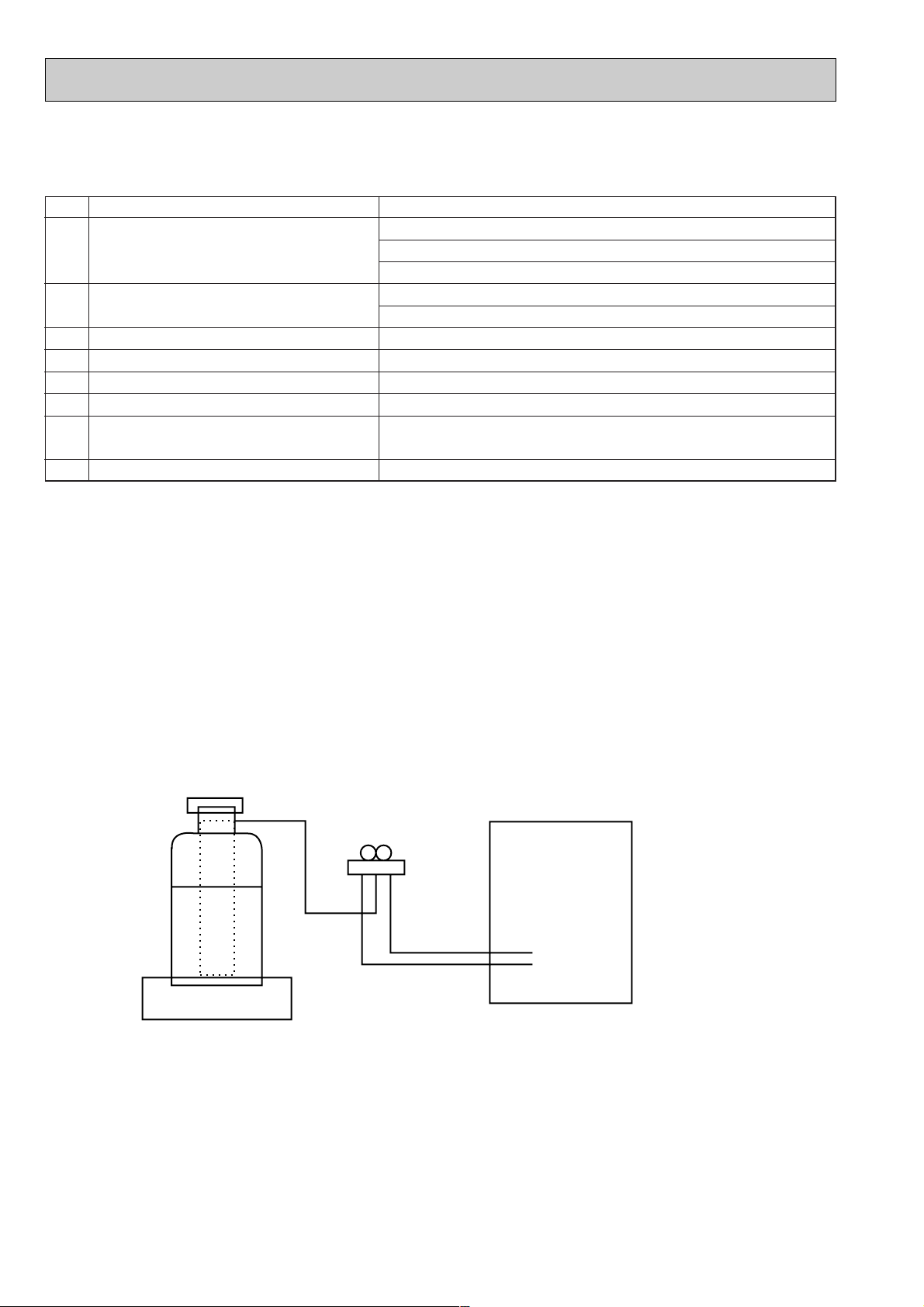
[3] Refrigerant recharging
(1) Refrigerant recharging process
1Direct charging from the cylinder.
·R407C cylinder are available on the market has a syphon pipe.
·Leave the syphon pipe cylinder standing and recharge it.
(By liquid refrigerant)
(2) Recharge in refrigerant leakage case
·After recovering the all refrigerant in the unit, proceed to working.
·Do not release the refrigerant in the air.
·After completing the repair service, recharge the cycle with the specified amount of
liquid refrigerant.
4
Page 5
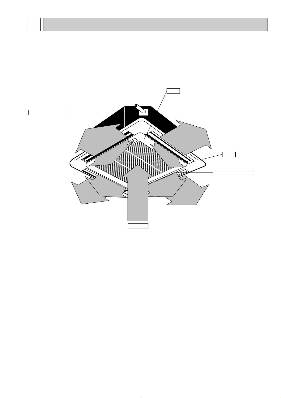
3
Auto Air Swing Vane
Disperses airflow up and
down and adjusts the angle
of airflow direction.
Grille
Filters
Remove dust and pollutants
from inhaled air
Horizontal Air Outlet
Sets airflow horizontal automatically
during cooling or dehumidifying.
Air Intake
Inhales air from room.
PART NAMES AND FUNCTIONS
● Indoor (Main) Unit
PLH-P1.6KAH, PLA-P1.6KA
PLH-P2KAH, PLA-P2KA
PLH-P2.5KAH, PLA-P2.5KA
PLH-P3KAH, PLA-P3KA
PLH-P4KAH, PLA-P4KA
PLH-P5KAH, PLA-P5KA
PLH-P6KAH, PLA-P6KA
5
Page 6
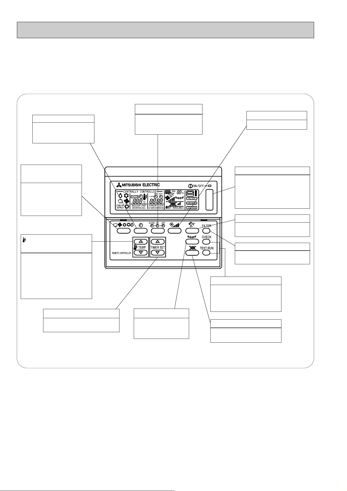
● Remote controller
● Operation buttons
TIMER button
This switches between
continuous operation and
the timer operation.
● Once the controls are set, the same operation mode can
be repeated by simply pressing the ON/OFF button.
TIME SETTING button
This sets of switches the
current time. start time and
stop time.
AIR SPEED button
This sets the fan speed.
OPERATION SWITCH
button
Press this button to
switch the cooler
electronic dry
(dehumidify) automatic
and heater modes.
TEMP. ADJUSTMENT
button
This sets the room
temperature The temperature
setting can be performed in
1°C units
Setting range
Cooler 19°C to 30°C
Heater 17°C to 28°C
TIMER ADJUSTMENT button
This adjust the current time, start
time and stop time.
LOUVER button
This switches the
horizontal fan motion
ON and OFF.
(This button does not
operate in this model)
ON/OFF button
This switches between the
operation and stop modes
each time it is pressed. The
lamp on this button lights
during operation.
AIR DIRECTION button
This adjusts the vertical angle
of the ventilation.
FILTER button
This resets the filter cleaning
indication display.
CHECK-TEST RUN button
Only press this button to
perform an inspection check
or test operation Do not use
it for normal operation.
VENTILATION button
This sets the ventilation fan
speed.
6
Page 7
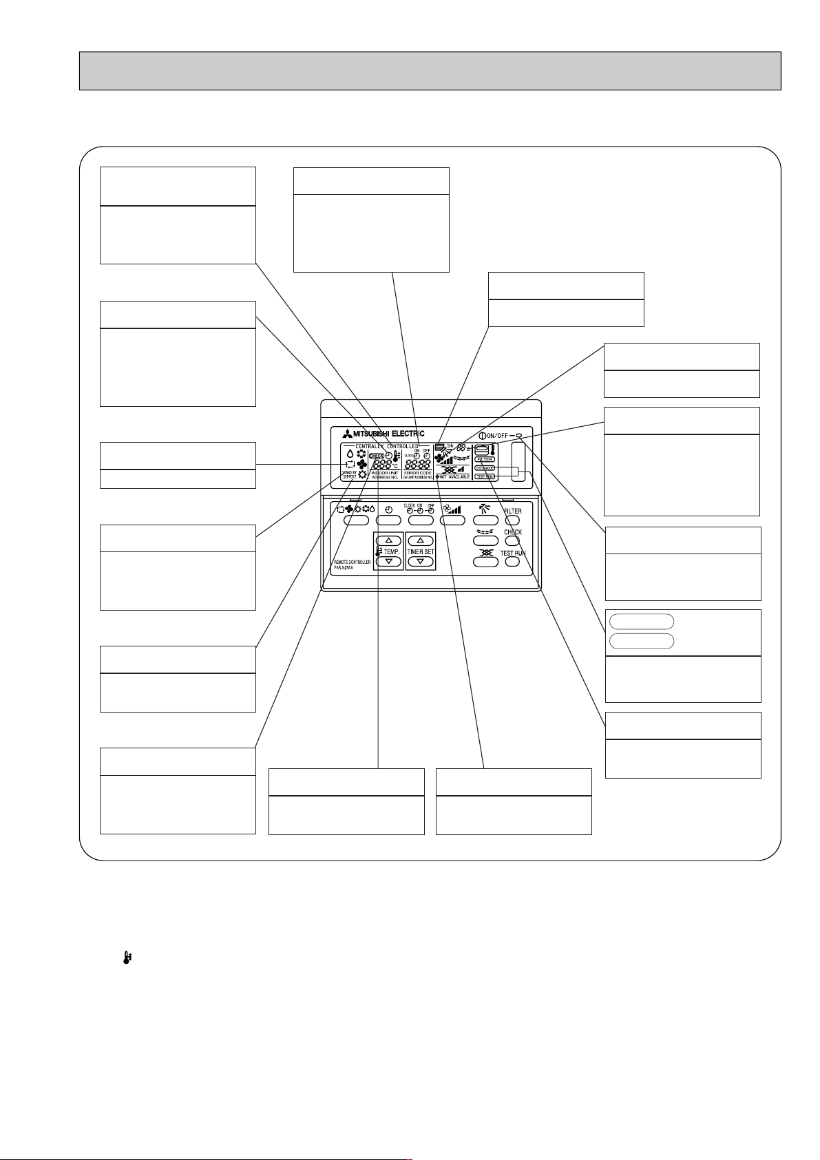
● Display
CENTRALLY
CONTROLLED display
This indicates when the unit is
controlled by optional features such
as central control type remote
controller.
TIMER display
This indicates when the continuous
operation and time operation modes
are set.
It also display the time for the timer
operation at the same time as when
it is set.
OPERATION MODE display
This indicates the operation mode.
STANDBY display
This indicates when the standby
mode is set from the time the sleep
operation starts until the heating air
is discharged.
DEFROST display
This indicates when the defrost
operation is performed.
CLOCK display
The current time , start time and stop
time can be displayed in ten second
intervals by pressing the time switch
button. The start time or stop time is
always displayed during the timer
operation.
In this display example on the
bottom left, a condition where all
display lamps light is shown for
explanation purposes although this
differs from actual operation.
AIR DIRECTION display
The selected fan speed is displayed.
FAN SPEED display
This displays the air direction.
ROOM TEMPERATURE display
The temperature of the suction air is
displayed during operation. The
display range is 8° to 39°C. The
display flashes 8°C when the actual
temperature is less than 8° and
flashes 39°C when the actual
temperature is greater than 39°C.
Operation lamp
This lamp lights during operation,
goes off when the unit stops and
flashes when a malfunction occurs.
CHECK MODE
TEST RUN
This display lights in the check mode
or when a test operation is
performed.
display
FILTER display
CHECK display
This indicates when a malfunction
has occurred in the unit which should
be checked.
SET TEMPERATURE display
This displays the selected setting
temperature.
Caution
● Only the Power display lights when the unit is stopped and power supplied to the unit.
● When power is turned ON for the first time the (CENTRAL CTRL) display appears to go off momentarily but this is not a
malfunction.
● When the central control remote control unit, which is sold separately, is used the ON-OFF button, operation switch button
and TEMP. adjustment button do not operate.
● “NOT AVAILABLE” is displayed when the Air speed button are pressed.This indicates that this room unit is not equipped
with the fan direction adjustment function and the louver function.
● When power is turned ON for the first time, it is normal that “H0” is displayed on the room temperature indication (For max.
2minutes). Please wait until this “H0” indication disappear then start the operation.
POWER display
This lamp lights when electricity is
supplied to the unit.
This lamp lights when the filter need
to be cleaned.
7
Page 8
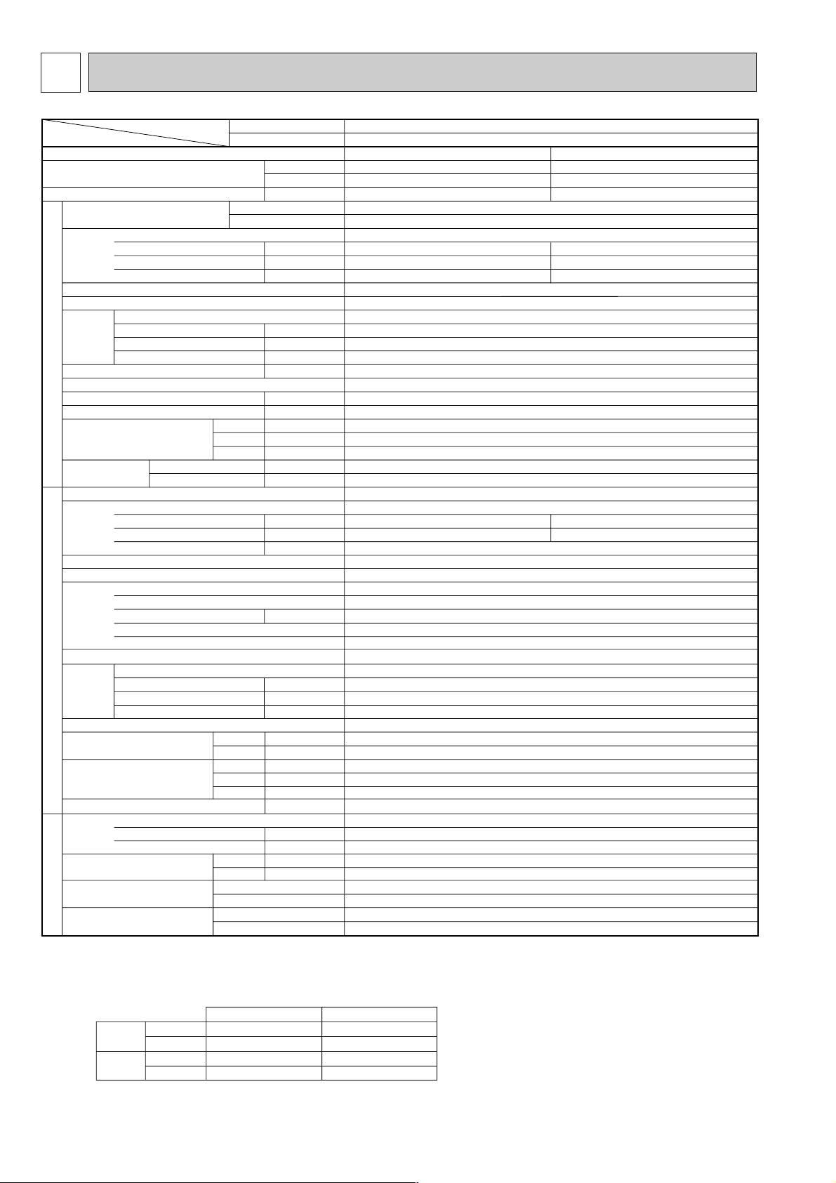
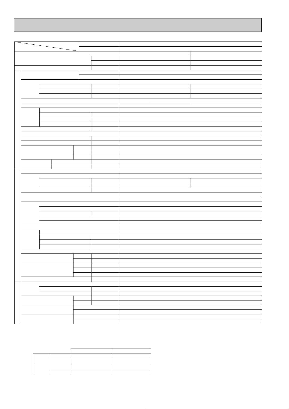
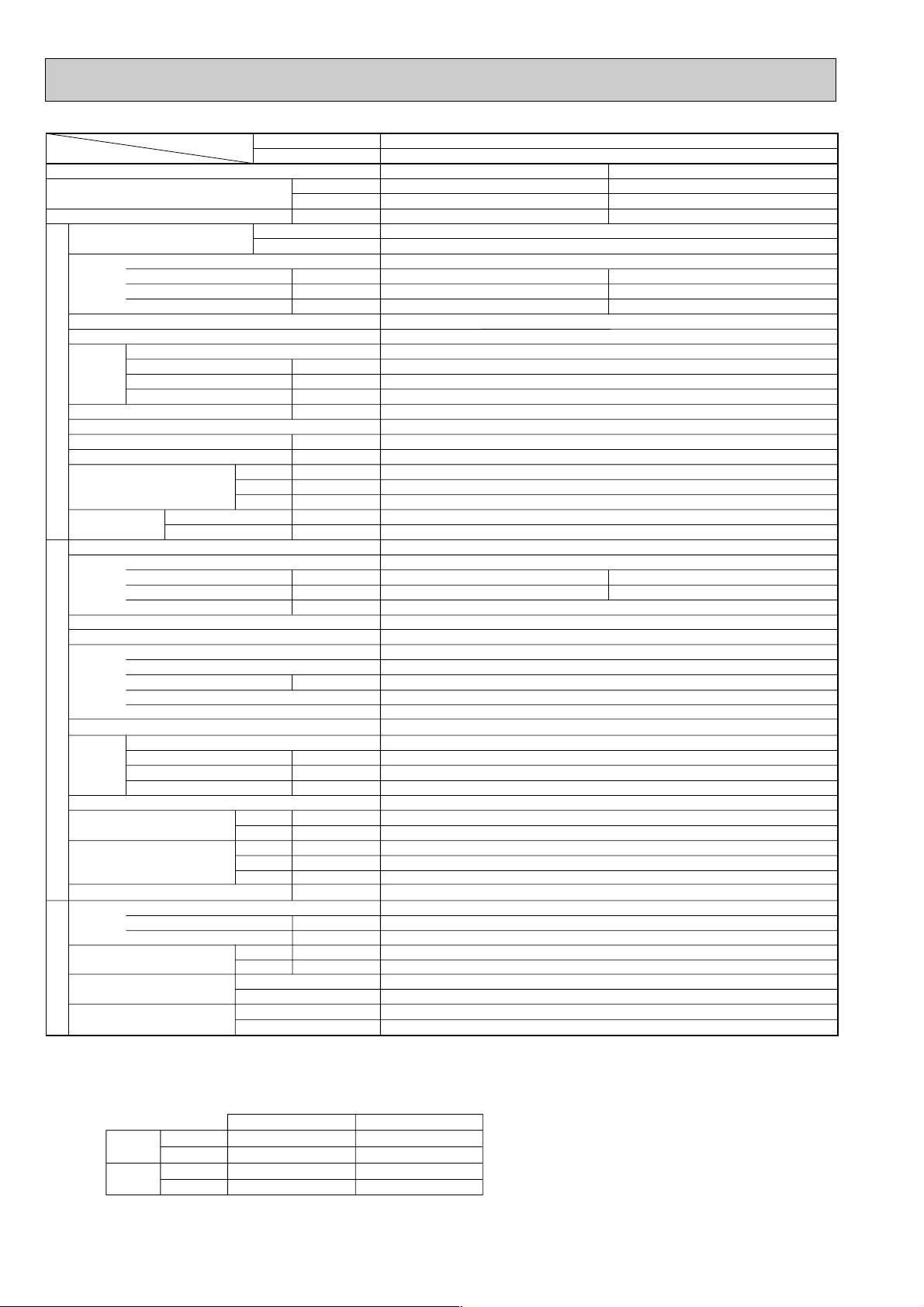
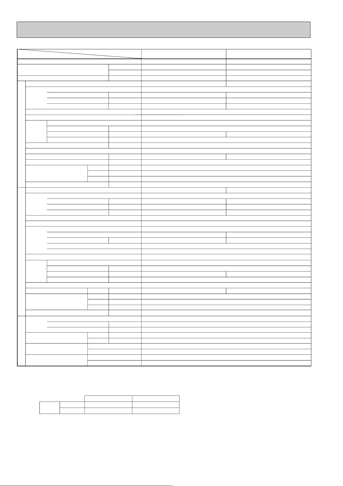
4 SPECIFICATIONS
1.Heat pump
Item
Function
Capacity w1
Total input w1
Service Ref.
Power supply(phase, cycle,voltage)
External finish
Heat exchanger
Fan Fan(drive) x No.
INDOOR UNITOUTDOOR UNIT
Booster heater w2
Operation control & Thermostat
Noise level(Lo-Mi1-Mi2-Hi)
Unit drain pipe I.D.
Dimensions
Weight
Service Ref.
Power supply (phase, cycle, voltage)
External finish
Refrigerant control
Compressor
Heat exchanger
Fan Fan(drive) x No.
Defrost method
Noise level
Dimensions
Weight
Refrigerant
Pipe size O.D.
Connection method
Between the indoor &
REFRIGERANT PIPING
outdoor unit
Notes1. Rating Conditions (ISO T1)
2. Guaranteed operating range
3. Above data based on indicated voltage
Input w2
Running current w2
Starting current w2
Fan motor output
Airflow(Lo-Mi1-Mi2-Hi)
External static pressure
Input
Running current
Starting current
Model
Motor output
Starter type
Protection devices
Fan motor output
Airflow
Crankcase heater
Charge
Oil (Model)
Cooling : Indoor : D.B. 27˚C(80˚F), W.B. 19˚C (66˚F) Outdoor : D.B. 35˚C(95˚F), W.B. 24˚C (75˚F)
Heating :Indoor : D.B. 20˚C(68˚F) Outdoor : D.B. 7˚C(45˚F), W.B. 6˚C (43˚F)
Refrigerant piping length (one way) : 5m (16ft)
Cooling
Heating
Indoor Unit 1 phase 240V 50Hz
Outdoor Unit 1 phase 240V 50Hz / 3 phase 415V 50Hz
Service Ref.
With Electric heater
Without Electric heater
Upper limit
Lower limit
Upper limit
Lower limit
With Electric heater
Without Electric heater
With Electric heater
Without Electric heater
3
m
Pa(mmAq)
W
D
H
m3/min(CFM
Cooling
Heating
W
D
H
Liquid
Gas
Indoor side
Outdoor side
Height difference
Piping length
Indoor
D.B. 35˚C, W.B. 22.5˚C
D.B. 19˚C, W.B. 15˚C
D.B. 28˚C
D.B. 17˚C
Btu/h
W
kW
kW
A
A
kW
/min(CFM)
kW
dB
mm(in.)
mm(in.)
mm(in.)
mm(in.)
kg(lbs)
kg(lbs)
kW
A
A
kW
Inner thermostat, HP switch,Discharge thermo. / Thermal rely, Discharge thermo, HP switch, Anti-phase protector.
kW
)
W
dB
dB
mm(in.)
mm(in.)
mm(in.)
kg(lbs)
kg(lbs)
L
mm(in.)
mm(in.)
D.B. 24˚C, W.B. 18˚C
D.B. -11˚C, W.B. -12˚C
Outdoor
D.B. 46˚C
D.B. -5˚C
PLH-P1.6KAH
Cooling
15,000
4,400
1.86
0.15
0.64
0.70
Galvanized sheets with gray heat insulation
13-14-15-16(459-494-530-565)
UNIT : 660(26) PANEL : 760(30)
UNIT : 660(26) PANEL : 760(30)
UNIT : 253(10) PANEL : 30(1-1/8)
UNIT : 20(44) PANEL : 3.7(8)
UNIT : 19(42) PANEL : 3.7(8)
Single, 50Hz, 220-240V / 3-ph, 50Hz, 380-415V(4wires)
1.71
7.66 / 2.67
PLA-P1.6KA
Heating
17,100(21,800)
5,000(6,400)
1.93(3.33)
PLH-P1.6KAH
PLA-P1.6KA
Single, 50Hz, 220-240V
0.10<1.40>
0.45<5.83>
0.50<5.83>
Plate fin coil
Turbo fan (direct) x 1
0.030
0(direct blow)
<1.4>
Remote controller & built-in
32-34-35.5-37
32(1-1/4)
PUH-P1.6VGA / YGA
1.83
8.19 / 2.86
36 / 20
Munsell 5Y 8/1
Linear Expansion Valve
Hermetic
RE277VHSM / RE277YFKM
1.3
Line start
Plate fin coil
Propeller (direct) x 1
0.070
45(1,590)
30
Reverse cycle
46
48
900(35-7/16)
330+20(13+3/4)
650 (25-5/8)
55(121)
R407C
2.6(5.7)
0.57 (Ester)MEL56
9.52 (3/8)
15.88 (5/8)
Flared
Flared
Max. 40m
Max. 40m
w1 : ( ) Shows the total rating.
w2 : < > Shows the only booster heater rating.
8
Page 9
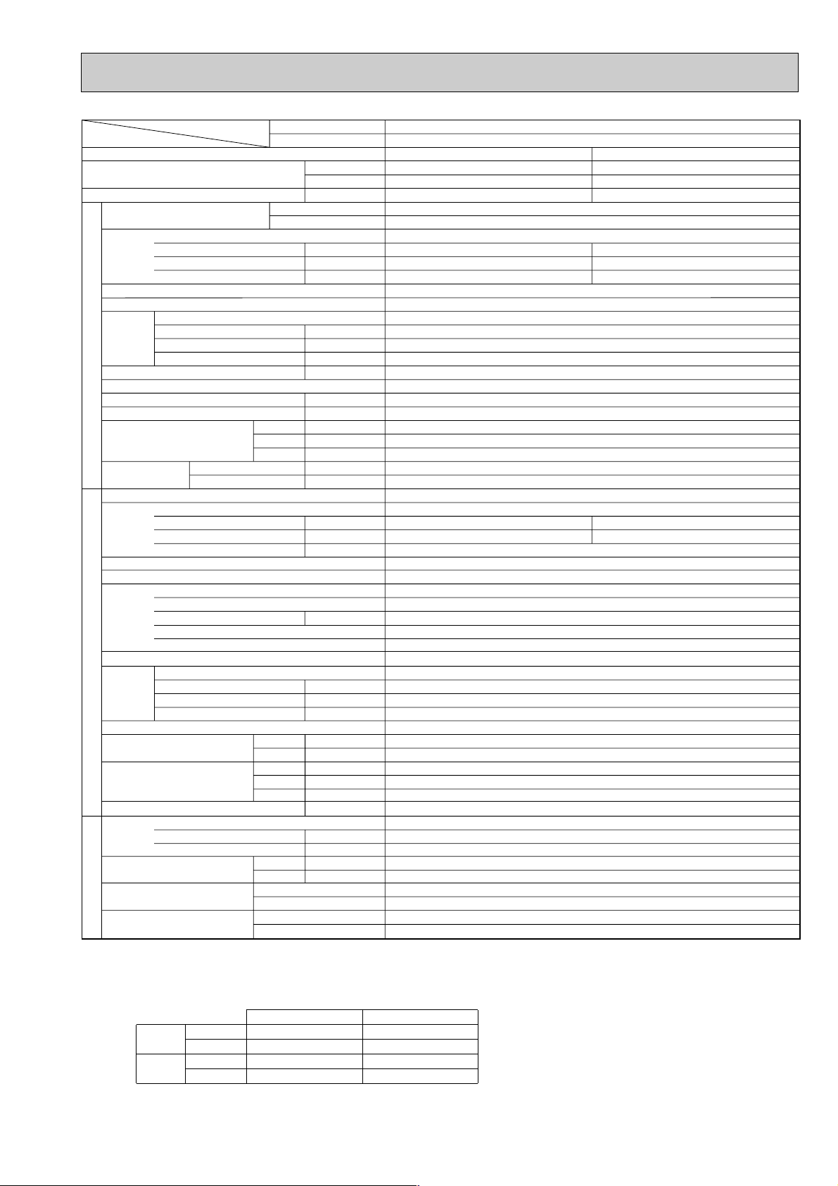
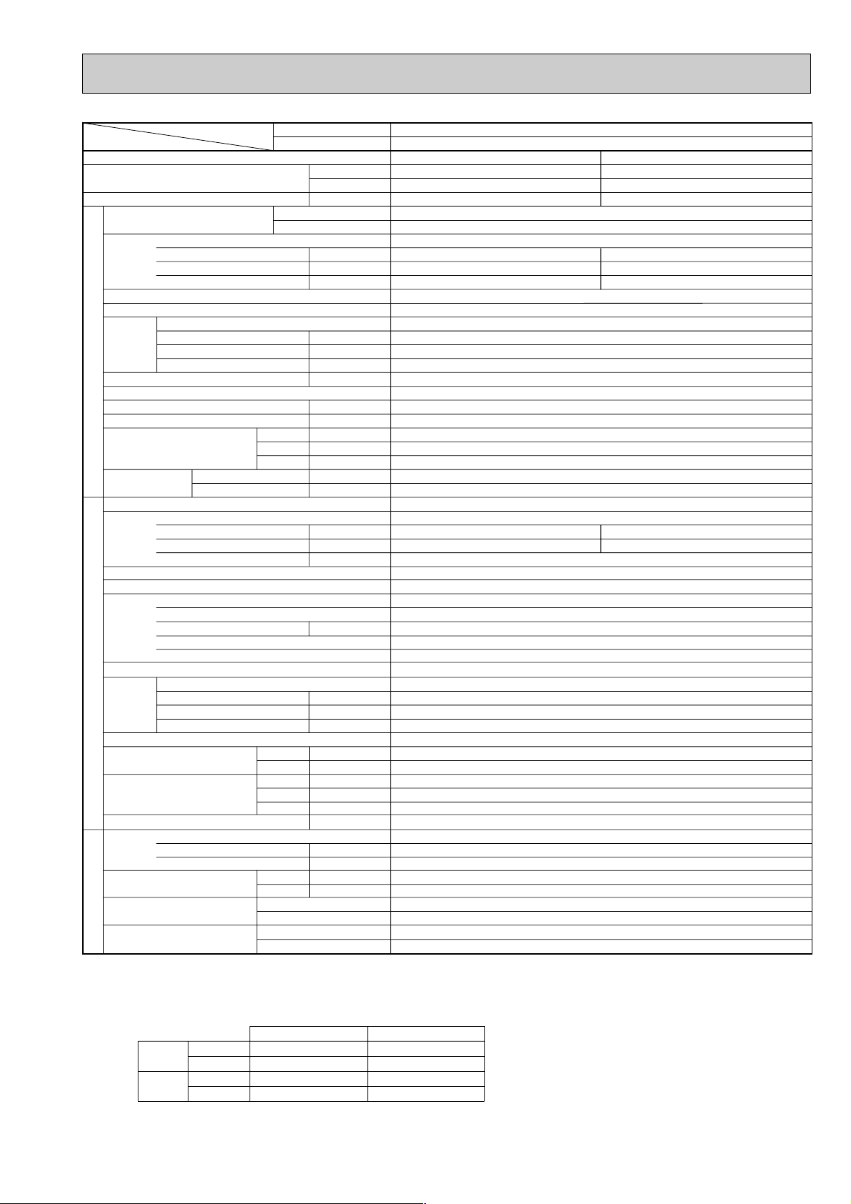
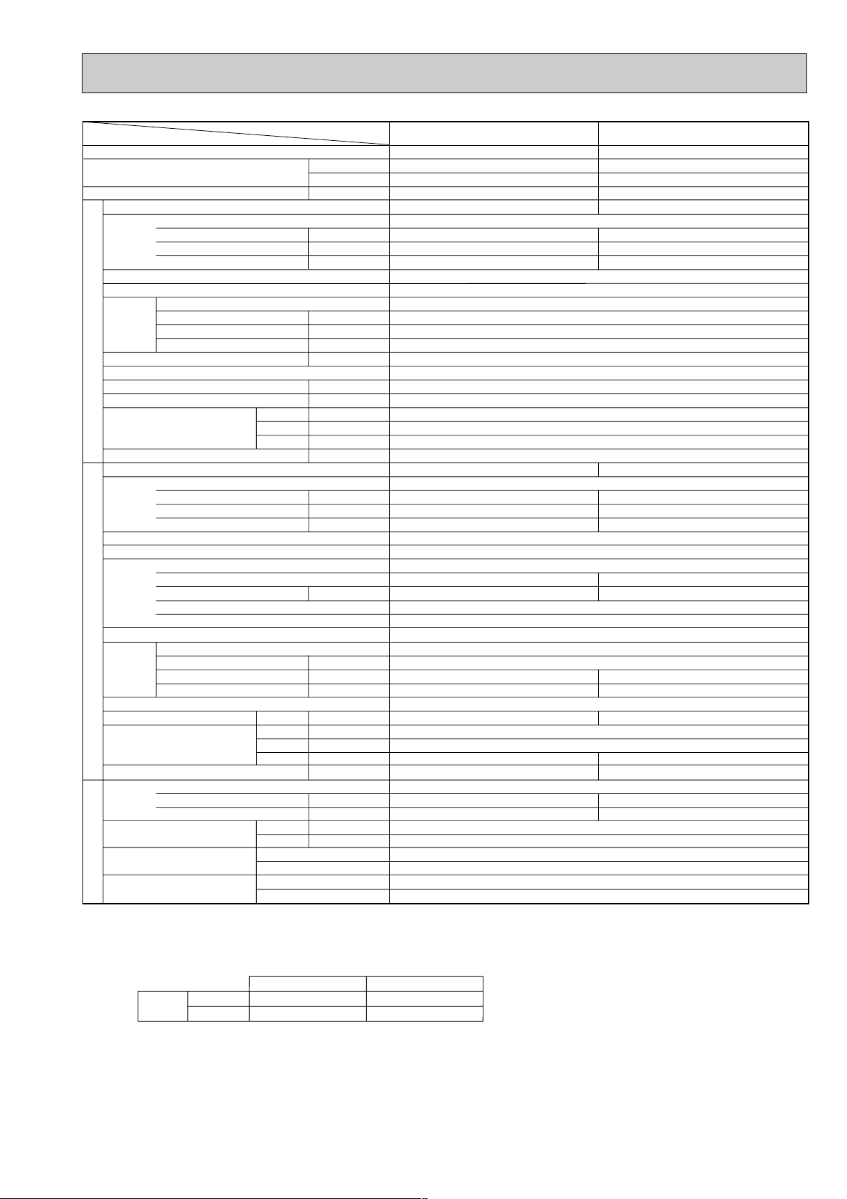
Item
Function
Capacity w1
Total input w1
Service Ref.
Power supply(phase, cycle,voltage)
External finish
Heat exchanger
Fan Fan(drive) x No.
INDOOR UNITOUTDOOR UNIT
Booster heater w2
Operation control & Thermostat
Noise level(Lo-Mi1-Mi2-Hi)
Unit drain pipe I.D.
Dimensions
Weight
Service Ref.
Power supply (phase, cycle, voltage)
External finish
Refrigerant control
Compressor
Heat exchanger
Fan Fan(drive) x No.
Defrost method
Noise level
Dimensions
Weight
Refrigerant
Pipe size O.D.
Connection method
Between the indoor &
REFRIGERANT PIPING
outdoor unit
Notes1. Rating Conditions (ISO T1)
2. Guaranteed operating range
3. Above data based on indicated voltage
Input w2
Running current w2
Starting current w2
Fan motor output
Airflow(Lo-Mi1-Mi2-Hi)
External static pressure
Input
Running current
Starting current
Model
Motor output
Starter type
Protection devices
Fan motor output
Airflow
Crankcase heater
Charge
Oil (Model)
Cooling : Indoor : D.B. 27˚C(80˚F), W.B. 19˚C (66˚F) Outdoor : D.B. 35˚C(95˚F), W.B. 24˚C (75˚F)
Heating :Indoor : D.B. 20˚C(68˚F) Outdoor : D.B. 7˚C(45˚F), W.B. 6˚C (43˚F)
Refrigerant piping length (one way) : 5m (16ft)
Cooling
Heating
Indoor Unit 1 phase 240V 50Hz
Outdoor Unit 1 phase 240V 50Hz / 3 phase 415V 50Hz
Service Ref.
With Electric heater
Without Electric heater
Upper limit
Lower limit
Upper limit
Lower limit
With Electric heater
Without Electric heater
Btu/h
W
With Electric heater
Without Electric heater
W
D
H
Cooling
Heating
W
D
H
Liquid
Gas
Indoor side
Outdoor side
Height difference
Piping length
Indoor
D.B. 35˚C, W.B. 22.5˚C
D.B. 19˚C, W.B. 15˚C
D.B. 28˚C
D.B. 17˚C
kW
kW
A
A
kW
3
/min(CFM)
m
Pa(mmAq)
kW
dB
mm(in.)
mm(in.)
mm(in.)
mm(in.)
kg(lbs)
kg(lbs)
kW
A
A
kW
kW
m3/min(CFM
W
dB
dB
mm(in.)
mm(in.)
mm(in.)
kg(lbs)
kg(lbs)
L
mm(in.)
mm(in.)
Cooling
18,400
5,400
2.62
0.14
0.65
0.72
Galvanized sheets with gray heat insulation
13-14-15-16(459-494-530-565)
UNIT : 660(26) PANEL : 760(30)
UNIT : 660(26) PANEL : 760(30)
UNIT : 253(10) PANEL : 30(1-1/8)
UNIT : 20(44) PANEL : 3.7(8)
UNIT : 19(42) PANEL : 3.7(8)
Single, 50Hz, 220-240V / 3-ph, 50Hz, 380-415V(4wires)
2.48
11.11 / 3.88
Inner thermostat, HP switch, Discharge thermo. / Thermal rely, Discharge thermo, HP switch, Anti-phase protector.
)
Outdoor
D.B. 46˚C
D.B. -5˚C
D.B. 24˚C, W.B. 18˚C
D.B. -11˚C, W.B. -12˚C
PLH-P2KAH
PLH-P2KAH
Single, 50Hz, 220-240V
Turbo fan (direct) x 1
0(direct blow)
Remote controller & built-in
32-34-35.5-37
PUH-P2VGA / YGA
Munsell 5Y 8/1
Linear Expansion Valve
NE38VMJM / NE38YEJM
Plate fin coil
Propeller (direct) x 1
Reverse cycle
900(35-7/16)
330+20(13+3/4)
1.2 (Ester)MEL56
w1 : ( ) Shows the total rating.
w2 : < > Shows the only booster heater rating.
PLA-P2KA
Heating
21,300(26,100)
6,250(7,650)
2.67(4.07)
PLA-P2KA
0.10<1.40>
0.45<5.83>
0.50<5.83>
Plate fin coil
0.030
<1.4>
32(1-1/4)
2.57
11.51 / 4.02
74 / 30
Hermetic
1.7
Line start
0.070
55(1,940)
38
48
49
855 (33-5/8)
71(157)
R407C
3.1(6.8)
9.52 (3/8)
15.88 (5/8)
Flared
Flared
Max. 40m
Max. 40m
9
Page 10
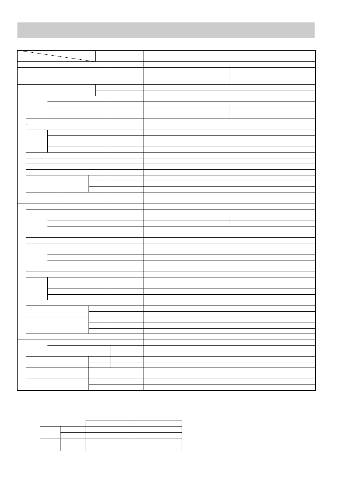
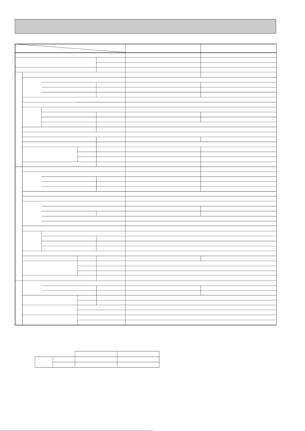
Item
Function
Capacity w1
Total input w1
Service Ref.
Power supply(phase, cycle,voltage)
External finish
Heat exchanger
Fan Fan(drive) x No.
INDOOR UNITOUTDOOR UNIT
Booster heater w2
Operation control & Thermostat
Noise level(Lo-Mi1-Mi2-Hi)
Unit drain pipe I.D.
Dimensions
Weight
Service Ref.
Power supply (phase, cycle, voltage)
External finish
Refrigerant control
Compressor
Heat exchanger
Fan Fan(drive) x No.
Defrost method
Noise level
Dimensions
Weight
Refrigerant
Pipe size O.D.
Connection method
Between the indoor &
REFRIGERANT PIPING
outdoor unit
Notes1. Rating Conditions (ISO T1)
2. Guaranteed operating range
3. Above data based on indicated voltage
Input w2
Running current w2
Starting current w2
Fan motor output
Airflow(Lo-Mi1-Mi2-Hi)
External static pressure
Input
Running current
Starting current
Model
Motor output
Starter type
Protection devices
Fan motor output
Airflow
Crankcase heater
Charge
Oil (Model)
Cooling : Indoor : D.B. 27˚C(80˚F), W.B. 19˚C (66˚F) Outdoor : D.B. 35˚C(95˚F), W.B. 24˚C (75˚F)
Heating :Indoor : D.B. 20˚C(68˚F) Outdoor : D.B. 7˚C(45˚F), W.B. 6˚C (43˚F)
Refrigerant piping length (one way) : 5m (16ft)
Cooling
Heating
Indoor Unit 1 phase 240V 50Hz
Outdoor Unit 1 phase 240V 50Hz / 3 phase 415V 50Hz
Service Ref.
With Electric heater
Without Electric heater
Upper limit
Lower limit
Upper limit
Lower limit
With Electric heater
Without Electric heater
Btu/h
W
With Electric heater
Without Electric heater
W
D
H
Cooling
Heating
W
D
H
Liquid
Gas
Indoor side
Outdoor side
Height difference
Piping length
Indoor
D.B. 35˚C, W.B. 22.5˚C
D.B. 19˚C, W.B. 15˚C
D.B. 28˚C
D.B. 17˚C
kW
kW
A
A
kW
3
/min(CFM)
m
Pa(mmAq)
kW
dB
mm(in.)
mm(in.)
mm(in.)
mm(in.)
kg(lbs)
kg(lbs)
kW
A
A
kW
kW
m3/min(CFM
W
dB
dB
mm(in.)
mm(in.)
mm(in.)
kg(lbs)
kg(lbs)
L
mm(in.)
mm(in.)
Cooling
21,500
6,300
2.77
0.14
0.61
0.67
Galvanized sheets with gray heat insulation
14-15-16-17 (494-530-565-600)
UNIT : 660(26) PANEL : 760(30)
UNIT : 660(26) PANEL : 760(30)
UNIT : 253(10) PANEL : 30(1-1/8)
UNIT : 21(46) PANEL : 3.7(8)
UNIT : 20(44) PANEL : 3.7(8)
Single, 50Hz, 220-240V / 3-ph, 50Hz, 380-415V(4wires)
2.63
11.78 / 4.11
Internal thermostat, HP switch, Discharge thermo. / Thermal rely, Discharge thermo, HP switch, Anti-phase protector.
)
Outdoor
D.B. 46˚C
D.B. -5˚C
D.B. 24˚C, W.B. 18˚C
D.B. -11˚C, W.B. -12˚C
PLH-P2.5KAH
PLA-P2.5KA
PLH-P2.5KAH
PLA-P2.5KA
Single, 50Hz, 220-240V
Turbo fan (direct) x 1
0(direct blow)
Remote controller & built-in
35-36.5-38-39.5
PUH-P2.5VGA / YGA
Munsell 5Y 8/1
Linear Expansion Valve
NE41VMJM / NE41YEJM
Propeller (direct) x 1
Reverse cycle
900(35-7/16)
330+20(13+3/4)
1.2 (Ester)MEL56
w1 : ( ) Shows the total rating.
w2 : < > Shows the only booster heater rating.
Heating
25,200(32,400)
7,400(9,500)
2.68(4.78)
0.10<2.10>
0.45<8.75>
0.50<8.75>
Plate fin coil
0.030
<2.1>
32(1-1/4)
2.58
11.55 / 4.03
77 / 32
Hermetic
1.9
Line start
Plate fin coil
0.070
50(1,770)
38
48
50
855 (33-5/8)
82(181)
R407C
3.3(7.3)
9.52 (3/8)
15.88 (5/8)
Flared
Flared
Max. 50m
Max. 50m
10
Page 11
Item
Function
Capacity w1
Total input w1
Service Ref.
Power supply(phase, cycle,voltage)
External finish
Heat exchanger
Fan Fan(drive) x No.
INDOOR UNITOUTDOOR UNIT
Booster heater w2
Operation control & Thermostat
Noise level(Lo-Mi1-Mi2-Hi)
Unit drain pipe I.D.
Dimensions
Weight
Service Ref.
Power supply (phase, cycle, voltage)
External finish
Refrigerant control
Compressor
Heat exchanger
Fan Fan(drive) x No.
Defrost method
Noise level
Dimensions
Weight
Refrigerant
Pipe size O.D.
Connection method
Between the indoor &
REFRIGERANT PIPING
outdoor unit
Notes1. Rating Conditions (ISO T1)
2. Guaranteed operating range
3. Above data based on indicated voltage
Input w2
Running current w2
Starting current w2
Fan motor output
Airflow(Lo-Mi1-Mi2-Hi)
External static pressure
Input
Running current
Starting current
Model
Motor output
Starter type
Protection devices
Fan motor output
Airflow
Crankcase heater
Charge
Oil (Model)
Cooling : Indoor : D.B. 27˚C(80˚F), W.B. 19˚C (66˚F) Outdoor : D.B. 35˚C(95˚F), W.B. 24˚C (75˚F)
Heating :Indoor : D.B. 20˚C(68˚F) Outdoor : D.B. 7˚C(45˚F), W.B. 6˚C (43˚F)
Refrigerant piping length (one way) : 5m (16ft)
Cooling
Heating
Indoor Unit 1 phase 240V 50Hz
Outdoor Unit 1 phase 240V 50Hz / 3 phase 415V 50Hz
Service Ref.
With Electric heater
Without Electric heater
Upper limit
Lower limit
Upper limit
Lower limit
With Electric heater
Without Electric heater
Btu/h
W
With Electric heater
Without Electric heater
W
D
H
Cooling
Heating
W
D
H
Liquid
Gas
Indoor side
Outdoor side
Height difference
Piping length
Indoor
D.B. 35˚C, W.B. 22.5˚C
D.B. 19˚C, W.B. 15˚C
D.B. 28˚C
D.B. 17˚C
kW
kW
A
A
kW
3
/min(CFM)
m
Pa(mmAq)
kW
dB
mm(in.)
mm(in.)
mm(in.)
mm(in.)
kg(lbs)
kg(lbs)
kW
A
A
kW
kW
m3/min(CFM
W
dB
dB
mm(in.)
mm(in.)
mm(in.)
kg(lbs)
kg(lbs)
L
mm(in.)
mm(in.)
Cooling
26,300
7,700
3.47
0.13
0.62
0.91
Galvanized sheets with gray heat insulation
15-16.5-18.5-20 (530-582-653-706)
UNIT : 840(33) PANEL : 950(37)
UNIT : 840(33) PANEL : 950(37)
UNIT : 290(11) PANEL : 30(1-1/8)
UNIT : 28(62) PANEL : 5(11)
UNIT : 26(57) PANEL : 5(11)
Single, 50Hz, 220-240V / 3-ph, 50Hz, 380-415V (4wires)
3.34
14.64/5.46
Internal thermostat, HP switch, Discharge thermo. / Thermal rely, Discharge thermo, HP switch, Anti-phase protector.
)
Outdoor
D.B. 46˚C
D.B. -5˚C
D.B. 24˚C, W.B. 18˚C
D.B. -11˚C, W.B. -12˚C
PLH-P3KAH
PLH-P3KAH
Single, 50Hz, 220-240V
Turbo fan (direct) x 1
0(direct blow)
Remote controller & built-in
PUH-P3VGA / YGA
Munsell 5Y 8/1
Linear Expansion Valve
NE52VNJM / NE52YDJM
Propeller (direct) x 1
Reverse cycle
900(35-7/16)
330+20(13+3/4)
1.6 (Ester)MEL56
w1 : ( ) Shows the total rating.
w2 : < > Shows the only booster heater rating.
PLA-P3KA
Heating
31,400(38,500)
9,200(11,300)
3.65(5.75)
PLA-P3KA
0.13<2.10>
0.62<8.75>
0.91<8.75>
Plate fin coil
0.070
<2.1>
32-34-37-39
32(1-1/4)
3.52
15.43/5.76
93/41
Hermetic
2.5
Line start
Plate fin coil
0.070
50(1,770)
38
49
51
855 (33-5/8)
82(181)
R407C
3.7(8.2)
9.52 (3/8)
15.88 (5/8)
Flared
Flared
Max. 50m
Max. 50m
11
Page 12
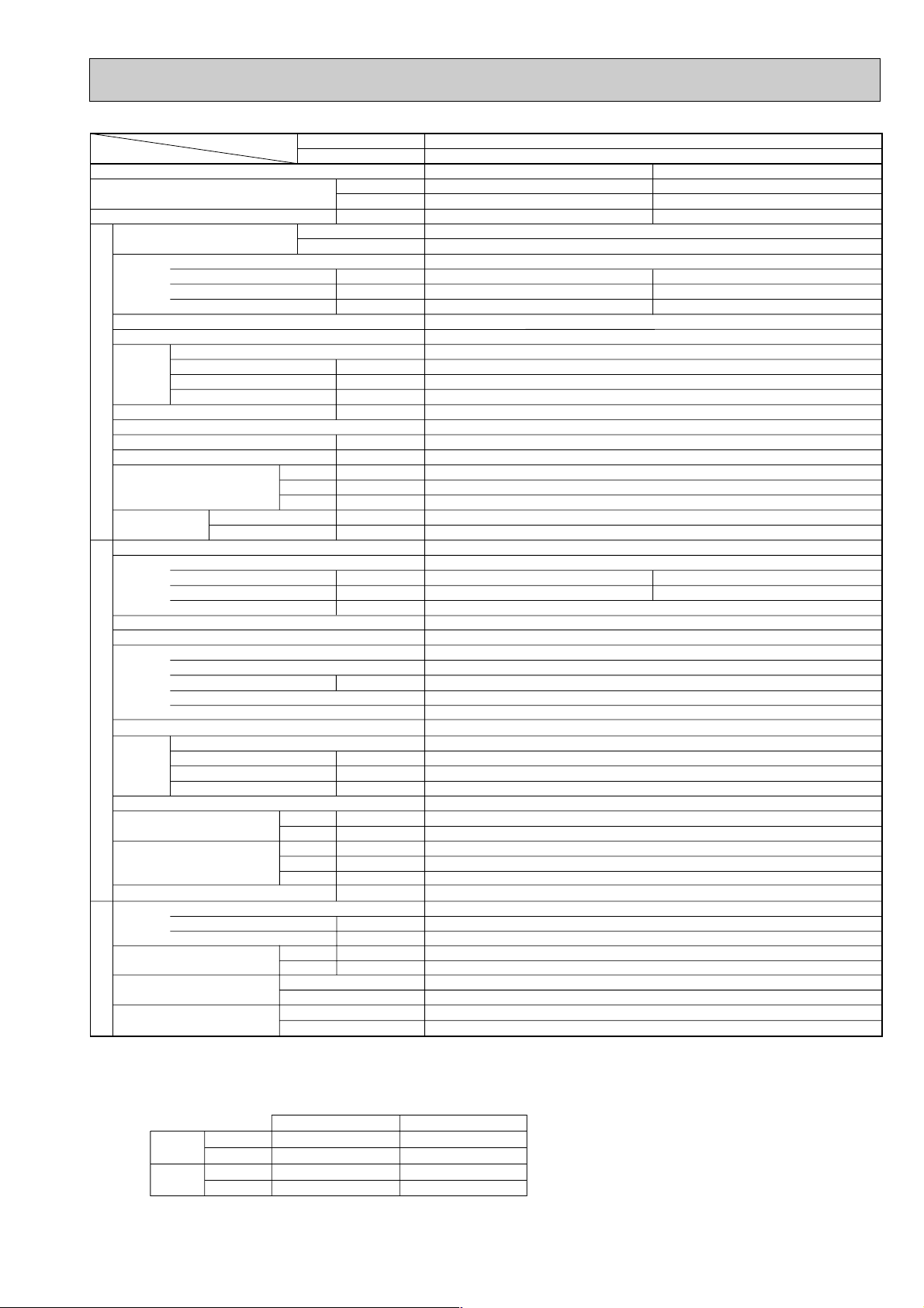
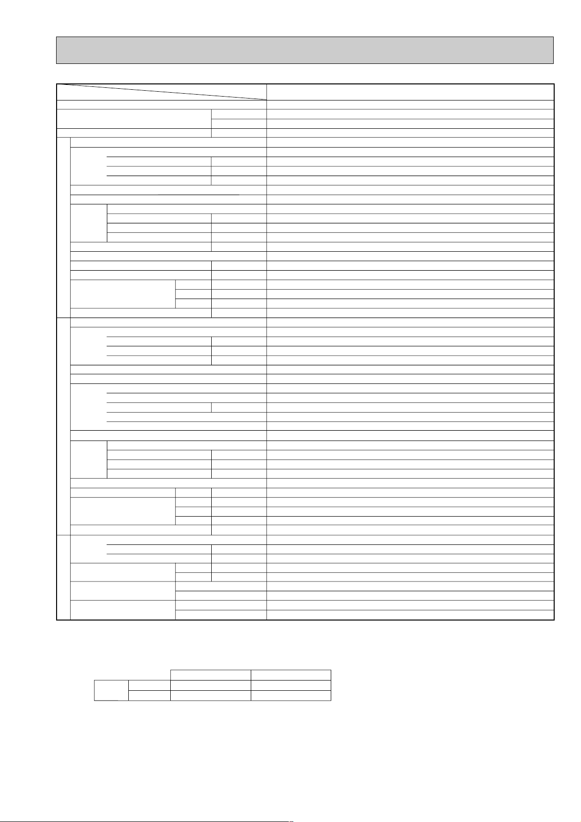
Item
Function
Capacity w1
Total input w1
Service Ref.
Power supply(phase, cycle,voltage)
External finish
Heat exchanger
Fan Fan(drive) x No.
INDOOR UNITOUTDOOR UNIT
Booster heater w2
Operation control & Thermostat
Noise level(Lo-Mi1-Mi2-Hi)
Unit drain pipe I.D.
Dimensions
Weight
Service Ref.
Power supply (phase, cycle, voltage)
External finish
Refrigerant control
Compressor
Heat exchanger
Fan Fan(drive) x No.
Defrost method
Noise level
Dimensions
Weight
Refrigerant
Pipe size O.D.
Connection method
Between the indoor &
REFRIGERANT PIPING
outdoor unit
Notes1. Rating Conditions (ISO T1)
2. Guaranteed operating range
3. Above data based on indicated voltage
Input w2
Running current w2
Starting current w2
Fan motor output
Airflow(Lo-Mi1-Mi2-Hi)
External static pressure
Input
Running current
Starting current
Model
Motor output
Starter type
Protection devices
Fan motor output
Airflow
Crankcase heater
Charge
Oil (Model)
Cooling : Indoor : D.B. 27˚C(80˚F), W.B. 19˚C (66˚F) Outdoor : D.B. 35˚C(95˚F), W.B. 24˚C (75˚F)
Heating :Indoor : D.B. 20˚C(68˚F) Outdoor : D.B. 7˚C(45˚F), W.B. 6˚C (43˚F)
Refrigerant piping length (one way) : 5m (16ft)
Cooling
Heating
Indoor Unit 1 phase 240V 50Hz
Outdoor Unit 3 phase 415V 50Hz
Service Ref.
With Electric heater
Without Electric heater
Upper limit
Lower limit
Upper limit
Lower limit
With Electric heater
Without Electric heater
Btu/h
W
With Electric heater
Without Electric heater
W
D
H
Cooling
Heating
W
D
H
Liquid
Gas
Indoor side
Outdoor side
Height difference
Piping length
Indoor
D.B. 35˚C, W.B. 22.5˚C
D.B. 19˚C, W.B. 15˚C
D.B. 28˚C
D.B. 17˚C
kW
kW
A
A
kW
3
/min(CFM)
m
Pa(mmAq)
kW
dB
mm(in.)
mm(in.)
mm(in.)
mm(in.)
kg(lbs)
kg(lbs)
kW
A
A
kW
kW
m3/min(CFM
W
dB
dB
mm(in.)
mm(in.)
mm(in.)
kg(lbs)
kg(lbs)
L
mm(in.)
mm(in.)
Cooling
33,100
9,700
3.57
0.21
0.99
1.38
Galvanized sheets with gray heat insulation
19.5-21.5-24-26(688-759-847-918)
UNIT : 840(33) PANEL : 950(37)
UNIT : 840(33) PANEL : 950(37)
UNIT : 290(11) PANEL : 30(1-1/8)
UNIT : 31(68) PANEL : 5(11)
UNIT : 29(64) PANEL : 5(11)
3-ph, 50Hz, 380-415V (4wires)
3.36
5.49
Anti-phase protector, Thermal relay, Discharge thermo, HP switch
)
Outdoor
D.B. 46˚C
D.B. -5˚C
D.B. 24˚C, W.B. 18˚C
D.B. -11˚C, W.B. -12˚C
PLH-P4KAH
PLH-P4KAH
Single, 50Hz, 220-240V
Turbo fan (direct) x 1
0(direct blow)
Remote controller & built-in
PUH-P4YGA
Munsell 5Y 8/1
Linear Expansion Valve
Propeller (direct) x 2
0.070+0.070
Reverse cycle
900(35-7/16)
330+20(13+3/4)
1,260 (49-5/8)
1.6 (Ester)MEL56
w1 : ( ) Shows the total rating.
w2 : < > Shows the only booster heater rating.
PLA-P4KA
Heating
36,200(43,300)
10,600(12,700)
3.75(5.85)
PLA-P4KA
0.21<2.10>
0.99<8.75>
1.38<8.75>
Plate fin coil
0.090
<2.1>
34-36-39-42
32(1-1/4)
3.54
5.79
45
Hermetic
NE56YDJM
2.7
Line start
Plate fin coil
85(3,000)
38
51
53
96(212)
R407C
4.0(8.8)
9.52 (3/8)
19.05 (3/4)
Flared
Flared
Max. 50m
Max. 50m
12
Page 13
Item
Function
Capacity w1
Total input w1
Service Ref.
Power supply(phase, cycle,voltage)
External finish
Heat exchanger
Fan Fan(drive) x No.
INDOOR UNITOUTDOOR UNIT
Booster heater w2
Operation control & Thermostat
Noise level(Lo-Mi1-Mi2-Hi)
Unit drain pipe I.D.
Dimensions
Weight
Service Ref.
Power supply (phase, cycle, voltage)
External finish
Refrigerant control
Compressor
Heat exchanger
Fan Fan(drive) x No.
Defrost method
Noise level
Dimensions
Weight
Refrigerant
Pipe size O.D.
Connection method
Between the indoor &
REFRIGERANT PIPING
outdoor unit
Notes1. Rating Conditions (ISO T1)
2. Guaranteed operating range
3. Above data based on indicated voltage
Input w2
Running current w2
Starting current w2
Fan motor output
Airflow(Lo-Mi1-Mi2-Hi)
External static pressure
Input
Running current
Starting current
Model
Motor output
Starter type
Protection devices
Fan motor output
Airflow
Crankcase heater
Charge
Oil (Model)
Cooling : Indoor : D.B. 27˚C(80˚F), W.B. 19˚C (66˚F) Outdoor : D.B. 35˚C(95˚F), W.B. 24˚C (75˚F)
Heating :Indoor : D.B. 20˚C(68˚F) Outdoor : D.B. 7˚C(45˚F), W.B. 6˚C (43˚F)
Refrigerant piping length (one way) : 5m (16ft)
Cooling
Heating
Indoor Unit 1 phase 240V 50Hz
Outdoor Unit 3 phase 415V 50Hz
Service Ref.
With Electric heater
Without Electric heater
Upper limit
Lower limit
Upper limit
Lower limit
With Electric heater
Without Electric heater
Btu/h
W
With Electric heater
Without Electric heater
W
D
H
Cooling
Heating
W
D
H
Liquid
Gas
Indoor side
Outdoor side
Height difference
Piping length
Indoor
D.B. 35˚C, W.B. 22.5˚C
D.B. 19˚C, W.B. 15˚C
D.B. 28˚C
D.B. 17˚C
kW
kW
A
A
kW
3
/min(CFM)
m
Pa(mmAq)
kW
dB
mm(in.)
mm(in.)
mm(in.)
mm(in.)
kg(lbs)
kg(lbs)
kW
A
A
kW
kW
m3/min(CFM
W
dB
dB
mm(in.)
mm(in.)
mm(in.)
kg(lbs)
kg(lbs)
L
mm(in.)
mm(in.)
Cooling
43,700
12,800
5.47
0.22
1.04
1.38
Galvanized sheets with gray heat insulation
22.5-25-27.5-30(794-883-971-1,059)
UNIT : 840(33) PANEL : 950(37)
UNIT : 1,360(54) PANEL : 1,470(58)
UNIT : 290(11) PANEL : 30(1-1/8)
UNIT : 39(86) PANEL : 9(20)
UNIT : 37(82) PANEL : 9(20)
3-ph, 50Hz, 380-415V (4wires)
5.25
8.39
Internal thermostat, Anti-phase protector, Thermal relay, HP switch, LP switch, Discharge thermo.
)
Outdoor
D.B. 46˚C
D.B. -5˚C
D.B. 24˚C, W.B. 18˚C
D.B. -11˚C, W.B. -12˚C
PLH-P5KAH
PLH-P5KAH
Single, 50Hz, 220-240V
Turbo fan (direct) x 1
0(direct blow)
Remote controller & built-in
PUH-P5YGA
Munsell 5Y 8/1
Linear Expansion Valve
Propeller (direct) x 2
0.075+0.075
Reverse cycle
1,050(41-5/16)
330+20(13+3/4)
1,260 (49-5/8)
2.0 (Ester)MEL32
w1 : ( ) Shows the total rating.
w2 : < > Shows the only booster heater rating.
PLA-P5KA
Heating
52,900(63,100)
15,500(18,500)
5.69(8.69)
PLA-P5KA
0.22<3.00>
1.04<12.50>
1.38<12.50>
Plate fin coil
0.090
<3.0>
36-38-40-43
32(1-1/4)
5.47
8.74
79
Hermetic
HE86YAA
4.3
Line start
Plate fin coil
95(3,360)
38
53
55
122(269)
R407C
5.8(12.8)
9.52 (3/8)
19.05 (3/4)
Flared
Flared
Max. 50m
Max. 50m
13
Page 14
Item
Function
Capacity w1
Total input w1
Service Ref.
Power supply(phase, cycle,voltage)
External finish
Heat exchanger
Fan Fan(drive) x No.
INDOOR UNITOUTDOOR UNIT
Booster heater w2
Operation control & Thermostat
Noise level(Lo-Mi1-Mi2-Hi)
Unit drain pipe I.D.
Dimensions
Weight
Service Ref.
Power supply (phase, cycle, voltage)
External finish
Refrigerant control
Compressor
Heat exchanger
Fan Fan(drive) x No.
Defrost method
Noise level
Dimensions
Weight
Refrigerant
Pipe size O.D.
Connection method
Between the indoor &
REFRIGERANT PIPING
outdoor unit
Notes1. Rating Conditions (ISO T1)
2. Guaranteed operating range
3. Above data based on indicated voltage
Input w2
Running current w2
Starting current w2
Fan motor output
Airflow(Lo-Mi1-Mi2-Hi)
External static pressure
Input
Running current
Starting current
Model
Motor output
Starter type
Protection devices
Fan motor output
Airflow
Crankcase heater
Charge
Oil (Model)
Cooling : Indoor : D.B. 27˚C(80˚F), W.B. 19˚C (66˚F) Outdoor : D.B. 35˚C(95˚F), W.B. 24˚C (75˚F)
Heating :Indoor : D.B. 20˚C(68˚F) Outdoor : D.B. 7˚C(45˚F), W.B. 6˚C (43˚F)
Refrigerant piping length (one way) : 5m (16ft)
Cooling
Heating
Indoor Unit 1 phase 240V 50Hz
Outdoor Unit 3 phase 415V 50Hz
Service Ref.
With Electric heater
Without Electric heater
Upper limit
Lower limit
Upper limit
Lower limit
With Electric heater
Without Electric heater
Btu/h
W
With Electric heater
Without Electric heater
W
D
H
Cooling
Heating
W
D
H
Liquid
Gas
Indoor side
Outdoor side
Height difference
Piping length
Indoor
D.B. 35˚C, W.B. 22.5˚C
D.B. 19˚C, W.B. 15˚C
D.B. 28˚C
D.B. 17˚C
kW
kW
A
A
kW
3
/min(CFM)
m
Pa(mmAq)
kW
dB
mm(in.)
mm(in.)
mm(in.)
mm(in.)
kg(lbs)
kg(lbs)
kW
A
A
kW
kW
m3/min(CFM
W
dB
dB
mm(in.)
mm(in.)
mm(in.)
kg(lbs)
kg(lbs)
L
mm(in.)
mm(in.)
Cooling
48,800
14,300
6.58
Single, 50Hz, 220-240V (4wires)
0.22
1.04
1.38
Galvanized sheets with gray heat insulation
25-27.5-30-33(883-971-1,059-1,165)
UNIT : 840(33) PANEL : 950(37)
UNIT : 1,360(54) PANEL : 1,470(58)
UNIT : 290(11) PANEL : 38(1-1/8)
UNIT : 39(86) PANEL : 9(20)
UNIT : 37(82) PANEL : 9(20)
3-ph, 50Hz, 380-415V (4wires)
6.36
10.17
Internal thermostat, Anit-phase protector, Thermal relay, HP switch, LP switch, Discharge thermo.
)
Outdoor
D.B. 46˚C
D.B. -5˚C
D.B. 24˚C, W.B. 18˚C
D.B. -11˚C, W.B. -12˚C
PLH-P6KAH
PLH-P6KAH
Turbo fan (direct) x 1
0(direct blow)
Remote controller & built-in
PUH-P6YGA
Munsell 5Y 8/1
Linear Expansion Valve
Propeller (direct) x 2
0.075+0.075
Reverse cycle
1,050(41-5/16)
330+20(13+3/4)
1,260 (49-5/8)
2.0 (Ester)MEL32
w1 : ( ) Shows the total rating.
w2 : < > Shows the only booster heater rating.
PLA-P6KA
Heating
57,300(67,600)
16,800(19,800)
6.65(9.65)
PLA-P6KA
0.22<3.00>
1.04<12.50>
1.38<12.50>
Plate fin coil
0.090
<3.0>
38-40-42-45
32(1-1/4)
6.43
10.28
84
Hermetic
HE101YAA
5.1
Line start
Plate fin coil
100(3,530)
38
55
57
122(269)
R407C
5.8(12.8)
9.52 (3/8)
19.05 (3/4)
Flared
Flared
Max. 50m
Max. 50m
14
Page 15
2.Cooling only type
Service Ref.
Item
Btu/h
W
kW
kW
A
A
kW
K/min(CFM)
Pa(mmAq)
kW
dB
mm(in.)
mm(in.)
mm(in.)
mm(in.)
kg(lbs)
kW
A
A
kW
kW
K
/min(CFM
)
W
dB
mm(in.)
mm(in.)
mm(in.)
kg(lbs)
kg(lbs)
L
mm(in.)
mm(in.)
Function
Capacity
Total input
Service Ref.
Power supply(phase, cycle,voltage)
Input
Running current
Starting current
External finish
Heat exchanger
Fan Fan(drive) x No.
Fan motor output
Airflow(Lo-Mi1-Mi2-Hi)
External static pressure
Booster heater
Operation control & Thermostat
Noise level(Lo-Mi1-Mi2-Hi)
Unit drain pipe I.D.
Dimensions
Weight
Service Ref.
Power supply (phase, cycle, voltage)
Input
Running current
Starting current
External finish
Refrigerant control
Compressor
Model
Motor output
Starter type
Protection devices
Heat exchanger
Fan Fan(drive) x No.
Fan motor output
Airflow
Crankcase heater
Defrost method
Noise level
Dimensions
Weight
Refrigerant
Charge
Oil (Model)
Pipe size O.D.
Connection method
Between the indoor &
outdoor unit
INDOOR UNITOUTDOOR UNIT
REFRIGERANT PIPING
PLA-P1.6KA
PLA-P1.6KA
PLA-P2KA
PLA-P2KA
Cooling
15,000
4,400
1.86
0.15
0.64
0.70
PU-P1.6VGA
1.71
7.66
36
RE277VHSM
1.3
45(1,590)
30
46
650 (25-5/8)
55(121)
2.6(5.7)
0.57(Ester)MEL56
Cooling
18,400
5,400
2.62
0.14
0.65
0.72
PU-P2VGA
2.48
11.11
74
NE38VMJM
1.7
55(1,940)
38
48
855(33-5/8)
71(157)
3.1(6.8)
1.2(Ester)MEL56
W
D
H
Cooling
W
D
H
Liquid
Gas
Indoor side
Outdoor side
Height difference
Piping length
Single, 50Hz, 220-240V
Galvanized sheets with gray heat insulation
Plate fin coil
Turbo fan (direct) x 1
0.030
13-14-15-16(459-494-530-565)
0(direct blow)
—
Remote controller & built-in
32-34-35.5-37
32(1-1/4)
Single, 50Hz, 220-240V
Munsell 5Y 8/1
Linear Expansion Valve
Hermetic
Line start
Inner thermostat, High pressure switch,Discharge thermo.
Plate fin coil
Propeller (direct) x 1
0.070
—
900(35-7/16)
330+20(13+3/4)
R407C
9.52 (3/8)
15.88 (5/8)
Flared
Flared
Max. 40m
Max. 40m
Notes1. Rating Conditions (ISO T1)
Cooling : Indoor : D.B. 27˚C(80˚F), W.B. 19˚C (66˚F) Outdoor : D.B. 35˚C(95˚F), W.B. 24˚C (75˚F)
Refrigerant piping length (one way) : 5m (16ft)
3. Above data based on indicated voltage
Indoor Unit 1 phase 240V 50Hz
Outdoor Unit 1 phase 240V 50Hz
2. Guaranteed operating range
Upper limit
Lower limit
Indoor
D.B. 35˚C, W.B. 22.5˚C
D.B. 19˚C, W.B. 15˚C
Outdoor
D.B. 46˚C
D.B. -5˚C
Cooling
UNIT : 660(26), PANEL : 760(30)
UNIT : 660(26), PANEL : 760(30)
UNIT : 253(10), PANEL : 30(1-1/8)
UNIT : 19(42), PANEL : 3.7(8)
15
Page 16
Service Ref.
Item
Btu/h
W
kW
kW
A
A
kW
K/min(CFM)
Pa(mmAq)
kW
dB
mm(in.)
mm(in.)
mm(in.)
mm(in.)
kg(lbs)
kW
A
A
kW
kW
K
/min(CFM
)
W
dB
mm(in.)
mm(in.)
mm(in.)
kg(lbs)
kg(lbs)
L
mm(in.)
mm(in.)
Function
Capacity
Total input
Service Ref.
Power supply(phase, cycle,voltage)
Input
Running current
Starting current
External finish
Heat exchanger
Fan Fan(drive) x No.
Fan motor output
Airflow(Lo-Mi1-Mi2-Hi)
External static pressure
Booster heater
Operation control & Thermostat
Noise level(Lo-Mi1-Mi2-Hi)
Unit drain pipe I.D.
Dimensions
Weight
Service Ref.
Power supply (phase, cycle, voltage)
Input
Running current
Starting current
External finish
Refrigerant control
Compressor
Model
Motor output
Starter type
Protection devices
Heat exchanger
Fan Fan(drive) x No.
Fan motor output
Airflow
Crankcase heater
Defrost method
Noise level
Dimensions
Weight
Refrigerant
Charge
Oil (Model)
Pipe size O.D.
Connection method
Between the indoor &
outdoor unit
INDOOR UNITOUTDOOR UNIT
REFRIGERANT PIPING
PLA-P2.5KA
PLA-P2.5KA
PLA-P3KA
PLA-P3KA
Cooling
21,500
6,300
2.77
0.14
0.61
0.67
0.030
14-15-16-17 (494-530-565-600)
35-36.5-38-39.5
PU-P2.5VGA
Single, 50Hz, 220-240V
2.63
11.78
77
NE41VMJM
1.9
48
3.3(7.3)
1.2(Ester)MEL56
Cooling
26,300
7,700
3.47
0.13
0.62
0.91
0.070
15-16.5-18.5-20 (530-582-653-706)
32-34-37-39
PU-P3VGA / YGA
Single, 50Hz, 220-240V / 3-ph, 50Hz, 380-415V(4wires)
3.34
14.64 / 5.46
93 / 41
NE52VNJM / NE52YDJM
2.5
49
3.7(8.2)
1.6(Ester)MEL56
W
D
H
Cooling
W
D
H
Liquid
Gas
Indoor side
Outdoor side
Height difference
Piping length
Notes1. Rating Conditions (ISO T1)
Cooling : Indoor : D.B. 27˚C(80˚F), W.B. 19˚C (66˚F) Outdoor : D.B. 35˚C(95˚F), W.B. 24˚C (75˚F)
Refrigerant piping length (one way) : 5m (16ft)
3. Above data based on indicated voltage
Indoor Unit 1 phase 240V 50Hz
Outdoor Unit 1 phase 240V 50Hz / 3 phase 415V 50Hz
2. Guaranteed operating range
Upper limit
Lower limit
Indoor
D.B. 35˚C, W.B. 22.5˚C
D.B. 19˚C, W.B. 15˚C
Outdoor
D.B. 46˚C
D.B. -5˚C
Cooling
UNIT : 660(26), PANEL : 760(30)
UNIT : 660(26), PANEL : 760(30)
UNIT : 253(10), PANEL : 30(1-1/8)
UNIT : 20(44), PANEL : 3.7(8)
UNIT : 840(33), PANEL : 950(37)
UNIT : 840(33), PANEL : 950(37)
UNIT : 290(11), PANEL : 30(1-1/8)
UNIT : 26(57), PANEL : 5(11)
Single, 50Hz, 220-240V
Galvanized sheets with gray heat insulation
Plate fin coil
Turbo fan (direct) x 1
0(direct blow)
—
Remote controller & built-in
32(1-1/4)
Munsell 5Y 8/1
Linear Expansion Valve
Hermetic
Line start
Internal thermostat, High switch,Discharge thermo. / Thermal rely, Discharge thermo, HP switch, Anti-phase protector.
Plate fin coil
Propeller (direct) x 1
0.070
50(1,770)
38
—
900(35-7/16)
330+20(13+3/4)
855(33-5/8)
82(181)
R407C
9.52 (3/8)
15.88 (5/8)
Flared
Flared
Max. 50m
Max. 50m
16
Page 17
Service Ref.
Item
Btu/h
W
kW
kW
A
A
kW
K/min(CFM)
Pa(mmAq)
kW
dB
mm(in.)
mm(in.)
mm(in.)
mm(in.)
kg(lbs)
kW
A
A
kW
kW
K
/min(CFM
)
W
dB
mm(in.)
mm(in.)
mm(in.)
kg(lbs)
kg(lbs)
L
mm(in.)
mm(in.)
Function
Capacity
Total input
Service Ref.
Power supply(phase, cycle,voltage)
Input
Running current
Starting current
External finish
Heat exchanger
Fan Fan(drive) x No.
Fan motor output
Airflow(Lo-Mi1-Mi2-Hi)
External static pressure
Booster heater
Operation control & Thermostat
Noise level(Lo-Mi1-Mi2-Hi)
Unit drain pipe I.D.
Dimensions
Weight
Service Ref.
Power supply (phase, cycle, voltage)
Input
Running current
Starting current
External finish
Refrigerant control
Compressor
Model
Motor output
Starter type
Protection devices
Heat exchanger
Fan Fan(drive) x No.
Fan motor output
Airflow
Crankcase heater
Defrost method
Noise level
Dimensions
Weight
Refrigerant
Charge
Oil (Model)
Pipe size O.D.
Connection method
Between the indoor &
outdoor unit
INDOOR UNITOUTDOOR UNIT
REFRIGERANT PIPING
W
D
H
Cooling
W
D
H
Liquid
Gas
Indoor side
Outdoor side
Height difference
Piping length
Notes1. Rating Conditions (ISO T1)
Cooling : Indoor : D.B. 27˚C(80˚F), W.B. 19˚C (66˚F) Outdoor : D.B. 35˚C(95˚F), W.B. 24˚C (75˚F)
Refrigerant piping length (one way) : 5m (16ft)
3. Above data based on indicated voltage
Indoor Unit 1 phase 240V 50Hz
Outdoor Unit 3 phase 415V 50Hz
2. Guaranteed operating range
Upper limit
Lower limit
Indoor
D.B. 35˚C, W.B. 22.5˚C
D.B. 19˚C, W.B. 15˚C
Outdoor
D.B. 46˚C
D.B. -5˚C
Cooling
PLA-P4KA
Cooling
33,100
9,700
3.57
PLA-P4KA
Single, 50Hz, 220-240V
0.21
0.99
1.38
Galvanized sheets with gray heat insulation
Plate fin coil
Turbo fan (direct) x 1
0.090
19.5-21.5-24-26(688-759-847-918)
0(direct blow)
—
Remote controller & built-in
34-36-39-42
32(1-1/4)
PU-P4YGA
3-ph, 50Hz, 380-415V (4wires)
3.36
5.49
45
Munsell 5Y 8/1
Linear Expansion Valve
Hermetic
NE56YDJM
2.7
Line start
Anti-phase protector, Thermal relay, Discharge thermo, HP switch
Plate fin coil
Propeller (direct) x 2
0.070+0.070
85(3,000)
38
—
51
900(35-7/16)
330+20(13+3/4)
1,260 (49-5/8)
96(212)
R407C
4.0(8.8)
1.6 (Ester)MEL56
9.52 (3/8)
19.05 (3/4)
Flared
Flared
Max. 50m
Max. 50m
UNIT : 840(33), PANEL : 950(37)
UNIT : 840(33), PANEL : 950(37)
UNIT : 290(11), PANEL : 30(1-1/8)
UNIT : 29(64), PANEL : 5(11)
17
Page 18
Service Ref.
Item
Btu/h
W
kW
kW
A
A
kW
K/min(CFM)
Pa(mmAq)
kW
dB
mm(in.)
mm(in.)
mm(in.)
mm(in.)
kg(lbs)
kW
A
A
kW
kW
K
/min(CFM
)
W
dB
mm(in.)
mm(in.)
mm(in.)
kg(lbs)
kg(lbs)
L
mm(in.)
mm(in.)
Function
Capacity
Total input
Service Ref.
Power supply(phase, cycle,voltage)
Input
Running current
Starting current
External finish
Heat exchanger
Fan Fan(drive) x No.
Fan motor output
Airflow(Lo-Mi1-Mi2-Hi)
External static pressure
Booster heater
Operation control & Thermostat
Noise level(Lo-Mi1-Mi2-Hi)
Unit drain pipe I.D.
Dimensions
Weight
Service Ref.
Power supply (phase, cycle, voltage)
Input
Running current
Starting current
External finish
Refrigerant control
Compressor
Model
Motor output
Starter type
Protection devices
Heat exchanger
Fan Fan(drive) x No.
Fan motor output
Airflow
Crankcase heater
Defrost method
Noise level
Dimensions
Weight
Refrigerant
Charge
Oil (Model)
Pipe size O.D.
Connection method
Between the indoor &
outdoor unit
INDOOR UNITOUTDOOR UNIT
REFRIGERANT PIPING
PLA-P5KA PLA-P6KA
Cooling
43,700
12,800
5.47
PLA-P5KA
0.22
1.04
1.38
22.5-25-27.5-30(794-883-971-1,059)
36-38-40-43
PU-P5YGA
5.25
8.39
79
HE86YAA
4.3
95(3,360)
53
Cooling
48,800
14,300
6.58
PLA-P6KA
0.22
1.04
1.38
25-27.5-30-33(883-971-1,059-1,165)
38-40-43-45
PU-P6YGA
6.36
10.17
84
HE101YAA
5.1
100(3,530)
57
W
D
H
Cooling
W
D
H
Liquid
Gas
Indoor side
Outdoor side
Height difference
Piping length
Notes1. Rating Conditions (ISO T1)
Cooling : Indoor : D.B. 27˚C(80˚F), W.B. 19˚C (66˚F) Outdoor : D.B. 35˚C(95˚F), W.B. 24˚C (75˚F)
Refrigerant piping length (one way) : 5m (16ft)
3. Above data based on indicated voltage
Indoor Unit 1 phase 240V 50Hz
Outdoor Unit 3 phase 415V 50Hz
2. Guaranteed operating range
Upper limit
Lower limit
Indoor
D.B. 35˚C, W.B. 22.5˚C
D.B. 19˚C, W.B. 15˚C
Outdoor
D.B. 46˚C
D.B. -5˚C
Cooling
UNIT : 840(33), PANEL : 950(37)
UNIT : 1,360(54), PANEL : 1,470(58)
UNIT : 290(11), PANEL : 30(1-1/8)
UNIT : 37(82), PANEL : 9(20)
Single, 50Hz, 220-240V
Galvanized sheets with gray heat insulation
Plate fin coil
Turbo fan (direct) x 1
0.090
0(direct blow)
—
Remote controller & built-in
32(1-1/4)
3-ph, 50Hz, 380-415V (4wires)
Munsell 5Y 8/1
Linear Expansion Valve
Hermetic
Line start
Internal thermostat, Anti-phase protector, Thermal relay, HP switch, LP switch, Discharge thermo.
Plate fin coil
Propeller (direct) x 2
0.075+0.075
38
—
1,050(41-5/16)
330+20(13+3/4)
1,260 (49-5/8)
122(269)
R407C
5.8(12.8)
2.0 (Ester)MEL32
9.52 (3/8)
19.05 (3/4)
Flared
Flared
Max. 50m
Max. 50m
18
Page 19
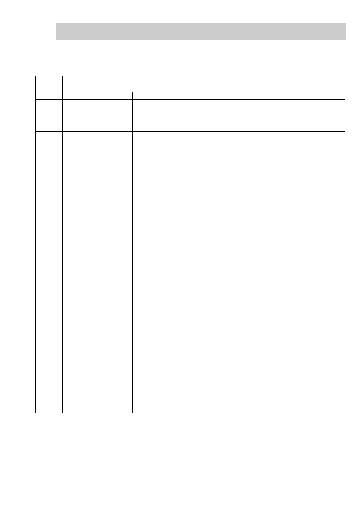
DATA5
Outdoor intake air D.B.(°C)
20 25 30
Indoor
Intake air
D.B.(°C)
Indoor
Intake air
W.B.(°C)
20
20
20
22
22
22
24
24
24
24
26
26
26
26
28
28
28
28
30
30
30
30
32
32
32
32
34
34
34
34
16
18
20
16
18
20
16
18
20
22
16
18
20
22
16
18
20
22
16
18
20
22
16
18
20
22
16
18
20
22
CA
4356
4664
5016
4356
4664
5016
4356
4664
5016
5346
4356
4664
5016
5346
4356
4664
5016
5346
4356
4664
5016
5346
4356
4664
5016
5346
4356
4664
5016
5346
SHC(W)
3049
2705
2307
3398
3078
2709
3746
3451
3110
2673
4095
3824
3511
3101
4356
4198
3912
3528
4356
4571
4314
3956
4356
4664
4715
4384
4356
4664
5016
4811
SHF
0.70
0.58
0.46
0.78
0.66
0.54
0.86
0.74
0.62
0.50
0.94
0.82
0.70
0.58
1.00
0.90
0.78
0.66
1.00
0.98
0.86
0.74
1.00
1.00
0.94
0.82
1.00
1.00
1.00
0.90
SHF
0.70
0.58
0.46
0.78
0.66
0.54
0.86
0.74
0.62
0.50
0.94
0.82
0.70
0.58
1.00
0.90
0.78
0.66
1.00
0.98
0.86
0.74
1.00
1.00
0.94
0.82
1.00
1.00
1.00
0.90
SHF
0.70
0.58
0.46
0.78
0.66
0.54
0.86
0.74
0.62
0.50
0.94
0.82
0.70
0.58
1.00
0.90
0.78
0.66
1.00
0.98
0.86
0.74
1.00
1.00
0.94
0.82
1.00
1.00
1.00
0.90
P.C.
1.49
1.52
1.56
1.49
1.52
1.56
1.49
1.52
1.56
1.60
1.49
1.52
1.56
1.60
1.49
1.52
1.56
1.60
1.49
1.52
1.56
1.60
1.49
1.52
1.56
1.60
1.49
1.52
1.56
1.60
CA
4224
4532
4906
4224
4532
4906
4224
4532
4906
5236
4224
4532
4906
5236
4224
4532
4906
5236
4224
4532
4906
5236
4224
4532
4906
5236
4224
4532
4906
5236
SHC(W)
2957
2629
2257
3296
2991
2649
3633
3354
3042
2618
3971
3716
3434
3037
4224
4079
3827
3456
4224
4441
4219
3875
4224
4532
4612
4294
4224
4532
4906
4712
P.C.
1.57
1.60
1.64
1.57
1.60
1.64
1.57
1.60
1.64
1.69
1.57
1.60
1.64
1.69
1.57
1.60
1.64
1.69
1.57
1.60
1.64
1.69
1.57
1.60
1.64
1.69
1.57
1.60
1.64
1.69
CA
4092
4378
4774
4092
4378
4774
4092
4378
4774
5104
4092
4378
4774
5104
4092
4378
4774
5104
4092
4378
4774
5104
4092
4378
4774
5104
4092
4378
4774
5104
SHC(W)
2864
2539
2196
3192
2889
2578
3519
3240
2960
2552
3846
3590
3342
2960
4092
3940
3724
3369
4092
4290
4106
3777
4092
4378
4488
4185
4092
4378
4774
4594
P.C.
1.66
1.71
1.75
1.66
1.71
1.75
1.66
1.71
1.75
1.80
1.66
1.71
1.75
1.80
1.66
1.71
1.75
1.80
1.66
1.71
1.75
1.80
1.66
1.71
1.75
1.80
1.66
1.71
1.75
1.80
1. PERFORMANCE DATA
1) COOLING CAPACITY(1)
PLH-P1.6KAH, PLA-P1.6KA
Note CA : Capacity (W)
P.C. : Power consumption (kW)
SHC(W) : Sensible heat capacity
SHF : Sensible heat factor
19
Page 20
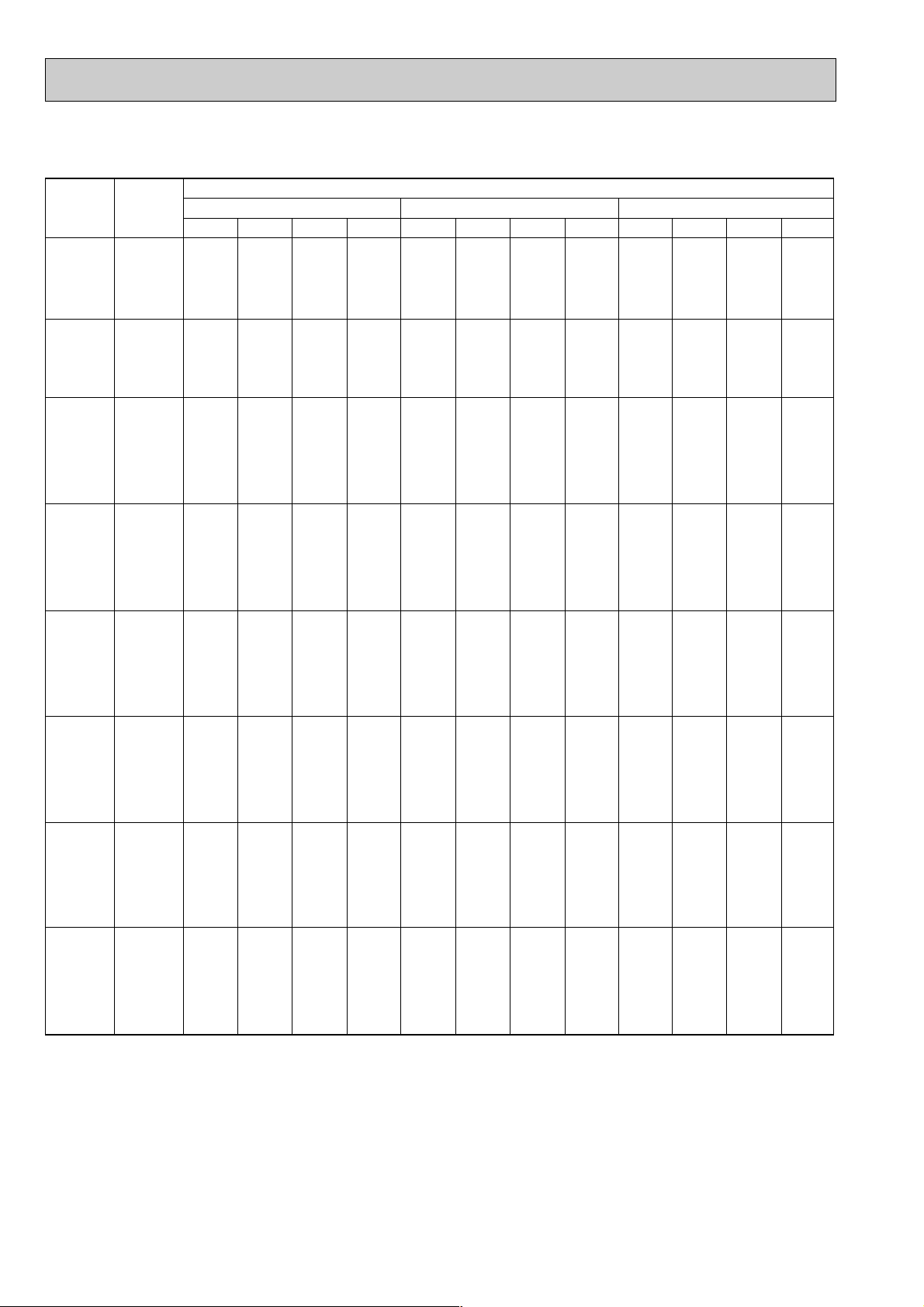
COOLING CAPACITY(2)
Outdoor intake air D.B.(°C)
35 40 45
Indoor
Intake air
D.B.(°C)
Indoor
Intake air
W.B.(°C)
20
20
20
22
22
22
24
24
24
24
26
26
26
26
28
28
28
28
30
30
30
30
32
32
32
32
34
34
34
34
16
18
20
16
18
20
16
18
20
22
16
18
20
22
16
18
20
22
16
18
20
22
16
18
20
22
16
18
20
22
CA
3916
4224
4576
3916
4224
4576
3916
4224
4576
4928
3916
4224
4576
4928
3916
4224
4576
4928
3916
4224
4576
4928
3916
4224
4576
4928
3916
4224
4576
4928
SHC(W)
2741
2450
2105
3054
2788
2471
3368
3126
2837
2464
3681
3464
3203
2858
3916
3802
3569
3252
3916
4140
3935
3647
3916
4224
4301
4041
3916
4224
4576
4435
SHF
0.70
0.58
0.46
0.78
0.66
0.54
0.86
0.74
0.62
0.50
0.94
0.82
0.70
0.58
1.00
0.90
0.78
0.66
1.00
0.98
0.86
0.74
1.00
1.00
0.94
0.82
1.00
1.00
1.00
0.90
SHF
0.70
0.58
0.46
0.78
0.66
0.54
0.86
0.74
0.62
0.50
0.94
0.82
0.70
0.58
1.00
0.90
0.78
0.66
1.00
0.98
0.86
0.74
1.00
1.00
0.94
0.82
1.00
1.00
1.00
0.90
SHF
0.70
0.58
0.46
0.78
0.66
0.54
0.86
0.74
0.62
0.50
0.94
0.82
0.70
0.58
1.00
0.90
0.78
0.66
1.00
0.98
0.86
0.74
1.00
1.00
0.94
0.82
1.00
1.00
1.00
0.90
P.C.
1.79
1.83
1.88
1.79
1.83
1.88
1.79
1.83
1.88
1.92
1.79
1.83
1.88
1.92
1.79
1.83
1.88
1.92
1.79
1.83
1.88
1.92
1.79
1.83
1.88
1.92
1.79
1.83
1.88
1.92
CA
3740
4092
4400
3740
4092
4400
3740
4092
4400
4752
3740
4092
4400
4752
3740
4092
4400
4752
3740
4092
4400
4752
3740
4092
4400
4752
3740
4092
4400
4752
SHC(W)
2618
2373
2024
2917
2701
2376
3216
3028
2728
2376
3516
3355
3080
2756
3740
3683
3432
3136
3740
4010
3784
3516
3740
4092
4136
3897
3740
4092
4400
4277
P.C.
1.92
1.97
2.01
1.92
1.97
2.01
1.92
1.97
2.01
2.06
1.92
1.97
2.01
2.06
1.92
1.97
2.01
2.06
1.92
1.97
2.01
2.06
1.92
1.97
2.01
2.06
1.92
1.97
2.01
2.06
CA
3652
3960
4268
3652
3960
4268
3652
3960
4268
4620
3652
3960
4268
4620
3652
3960
4268
4620
3652
3960
4268
4620
3652
3960
4268
4620
3652
3960
4268
4620
SHC(W)
2556
2297
1963
2849
2614
2305
3141
2930
2646
2310
3433
3247
2988
2680
3652
3564
3329
3049
3652
3881
3670
3419
3652
3960
4012
3788
3652
3960
4268
4158
P.C.
2.01
2.06
2.10
2.01
2.06
2.10
2.01
2.06
2.10
2.16
2.01
2.06
2.10
2.16
2.01
2.06
2.10
2.16
2.01
2.06
2.10
2.16
2.01
2.06
2.10
2.16
2.01
2.06
2.10
2.16
PLH-P1.6KAH, PLA-P1.6KA
Note CA : Capacity (W)
P.C. : Power consumption (kW)
SHC(W) : Sensible heat capacity
SHF : Sensible heat factor
20
Page 21
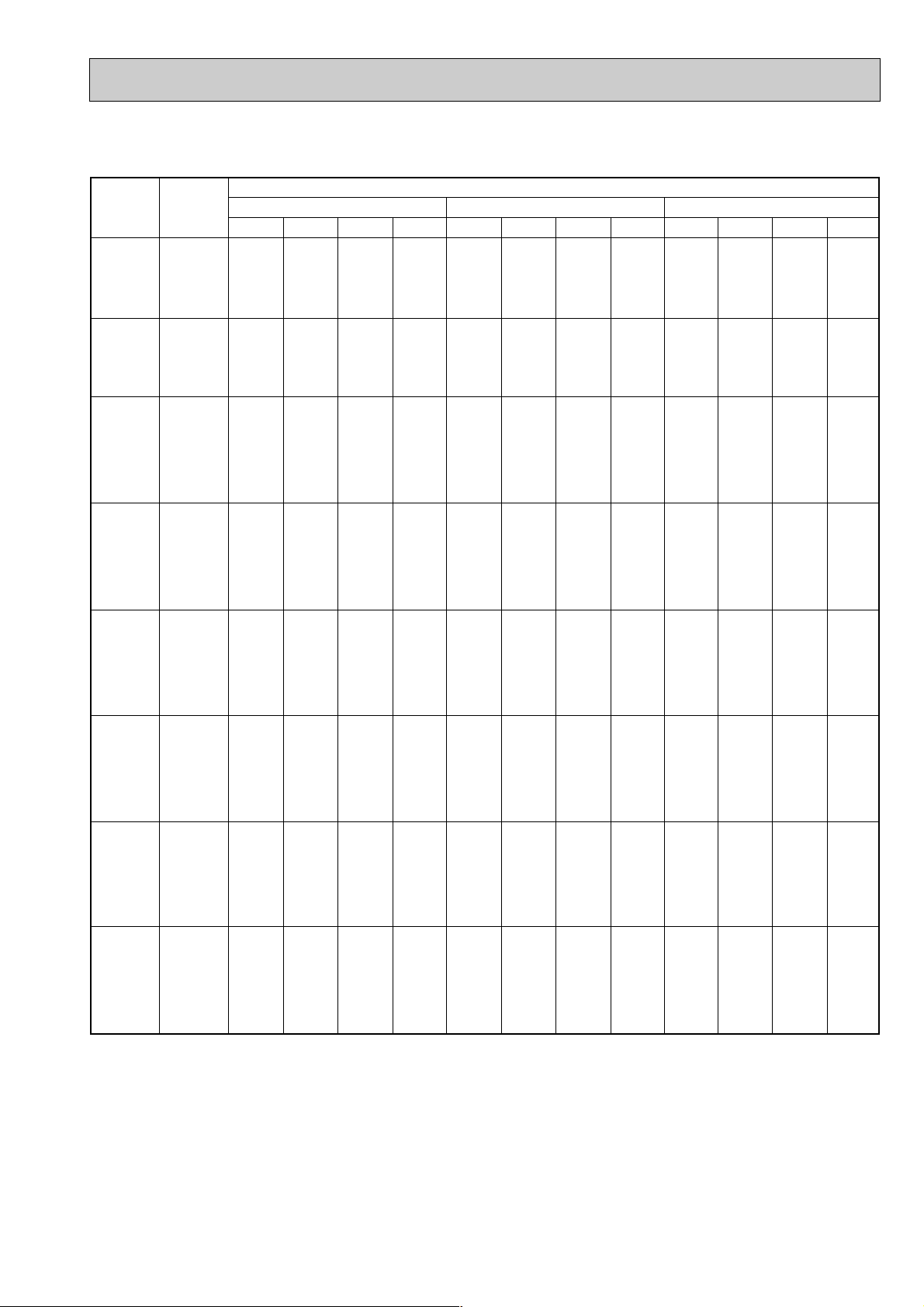
COOLING CAPACITY(3)
Outdoor intake air D.B.(°C)
20 25 30
Indoor
Intake air
D.B.(°C)
Indoor
Intake air
W.B.(°C)
20
20
20
22
22
22
24
24
24
24
26
26
26
26
28
28
28
28
30
30
30
30
32
32
32
32
34
34
34
34
16
18
20
16
18
20
16
18
20
22
16
18
20
22
16
18
20
22
16
18
20
22
16
18
20
22
16
18
20
22
CA
5346
5724
6156
5346
5724
6156
5346
5724
6156
6561
5346
5724
6156
6561
5346
5724
6156
6561
5346
5724
6156
6561
5346
5724
6156
6561
5346
5724
6156
6561
SHC(W)
3421
2976
2462
3849
3434
2955
4277
3892
3447
2887
4704
4350
3940
3412
5132
4808
4432
3937
5346
5266
4925
4461
5346
5724
5417
4986
5346
5724
5910
5511
SHF
0.64
0.52
0.40
0.72
0.60
0.48
0.80
0.68
0.56
0.44
0.88
0.76
0.64
0.52
0.96
0.84
0.72
0.60
1.00
0.92
0.80
0.68
1.00
1.00
0.88
0.76
1.00
1.00
0.96
0.84
SHF
0.64
0.52
0.40
0.72
0.60
0.48
0.80
0.68
0.56
0.44
0.88
0.76
0.64
0.52
0.96
0.84
0.72
0.60
1.00
0.92
0.80
0.68
1.00
1.00
0.88
0.76
1.00
1.00
0.96
0.84
SHF
0.64
0.52
0.40
0.72
0.60
0.48
0.80
0.68
0.56
0.44
0.88
0.76
0.64
0.52
0.96
0.84
0.72
0.60
1.00
0.92
0.80
0.68
1.00
1.00
0.88
0.76
1.00
1.00
0.96
0.84
P.C.
2.10
2.14
2.20
2.10
2.14
2.20
2.10
2.14
2.20
2.25
2.10
2.14
2.20
2.25
2.10
2.14
2.20
2.25
2.10
2.14
2.20
2.25
2.10
2.14
2.20
2.25
2.10
2.14
2.20
2.25
CA
5184
5562
6021
5184
5562
6021
5184
5562
6021
6426
5184
5562
6021
6426
5184
5562
6021
6426
5184
5562
6021
6426
5184
5562
6021
6426
5184
5562
6021
6426
SHC(W)
3318
2892
2408
3732
3337
2890
4147
3782
3372
2827
4562
4227
3853
3342
4977
4672
4335
3856
5184
5117
4817
4370
5184
5562
5298
4884
5184
5562
5780
5398
P.C.
2.21
2.25
2.31
2.21
2.25
2.31
2.21
2.25
2.31
2.38
2.21
2.25
2.31
2.38
2.21
2.25
2.31
2.38
2.21
2.25
2.31
2.38
2.21
2.25
2.31
2.38
2.21
2.25
2.31
2.38
CA
5022
5373
5859
5022
5373
5859
5022
5373
5859
6264
5022
5373
5859
6264
5022
5373
5859
6264
5022
5373
5859
6264
5022
5373
5859
6264
5022
5373
5859
6264
SHC(W)
3214
2794
2344
3616
3224
2812
4018
3654
3281
2756
4419
4083
3750
3257
4821
4513
4218
3758
5022
4943
4687
4260
5022
5373
5156
4761
5022
5373
5625
5262
P.C.
2.34
2.41
2.46
2.34
2.41
2.46
2.34
2.41
2.46
2.54
2.34
2.41
2.46
2.54
2.34
2.41
2.46
2.54
2.34
2.41
2.46
2.54
2.34
2.41
2.46
2.54
2.34
2.41
2.46
2.54
PLH-P2KAH, PLA-P2KA
Note CA : Capacity (W)
P.C. : Power consumption (kW)
SHC(W) : Sensible heat capacity
SHF : Sensible heat factor
21
Page 22

COOLING CAPACITY(4)
Outdoor intake air D.B.(°C)
35 40 45
Indoor
Intake air
D.B.(°C)
Indoor
Intake air
W.B.(°C)
20
20
20
22
22
22
24
24
24
24
26
26
26
26
28
28
28
28
30
30
30
30
32
32
32
32
34
34
34
34
16
18
20
16
18
20
16
18
20
22
16
18
20
22
16
18
20
22
16
18
20
22
16
18
20
22
16
18
20
22
CA
4806
5184
5616
4806
5184
5616
4806
5184
5616
6048
4806
5184
5616
6048
4806
5184
5616
6048
4806
5184
5616
6048
4806
5184
5616
6048
4806
5184
5616
6048
SHC(W)
3076
2696
2246
3460
3110
2696
3845
3525
3145
2661
4229
3940
3594
3145
4614
4355
4044
3629
4806
4769
4493
4113
4806
5184
4942
4596
4806
5184
5391
5080
SHF
0.64
0.52
0.40
0.72
0.60
0.48
0.80
0.68
0.56
0.44
0.88
0.76
0.64
0.52
0.96
0.84
0.72
0.60
1.00
0.92
0.80
0.68
1.00
1.00
0.88
0.76
1.00
1.00
0.96
0.84
SHF
0.64
0.52
0.40
0.72
0.60
0.48
0.80
0.68
0.56
0.44
0.88
0.76
0.64
0.52
0.96
0.84
0.72
0.60
1.00
0.92
0.80
0.68
1.00
1.00
0.88
0.76
1.00
1.00
0.96
0.84
SHF
0.64
0.52
0.40
0.72
0.60
0.48
0.80
0.68
0.56
0.44
0.88
0.76
0.64
0.52
0.96
0.84
0.72
0.60
1.00
0.92
0.80
0.68
1.00
1.00
0.88
0.76
1.00
1.00
0.96
0.84
P.C.
2.52
2.58
2.65
2.52
2.58
2.65
2.52
2.58
2.65
2.70
2.52
2.58
2.65
2.70
2.52
2.58
2.65
2.70
2.52
2.58
2.65
2.70
2.52
2.58
2.65
2.70
2.52
2.58
2.65
2.70
CA
4590
5022
5400
4590
5022
5400
4590
5022
5400
5832
4590
5022
5400
5832
4590
5022
5400
5832
4590
5022
5400
5832
4590
5022
5400
5832
4590
5022
5400
5832
SHC(W)
2938
2611
2160
3305
3013
2592
3672
3415
3024
2566
4039
3817
3456
3033
4406
4218
3888
3499
4590
4620
4320
3966
4590
5022
4752
4432
4590
5022
5184
4899
P.C.
2.70
2.78
2.83
2.70
2.78
2.83
2.70
2.78
2.83
2.91
2.70
2.78
2.83
2.91
2.70
2.78
2.83
2.91
2.70
2.78
2.83
2.91
2.70
2.78
2.83
2.91
2.70
2.78
2.83
2.91
CA
4374
4698
5076
4374
4698
5076
4374
4698
5076
5508
4374
4698
5076
5508
4374
4698
5076
5508
4374
4698
5076
5508
4374
4698
5076
5508
4374
4698
5076
5508
SHC(W)
2799
2443
2030
3149
2819
2436
3499
3195
2843
2424
3849
3570
3249
2864
4199
3946
3655
3305
4374
4322
4061
3745
4374
4698
4467
4186
4374
4698
4873
4627
P.C.
2.92
2.99
3.04
2.92
2.99
3.04
2.92
2.99
3.04
3.09
2.92
2.99
3.04
3.09
2.92
2.99
3.04
3.09
2.92
2.99
3.04
3.09
2.92
2.99
3.04
3.09
2.92
2.99
3.04
3.09
PLH-P2KAH, PLA-P2KA
Note CA : Capacity (W)
P.C. : Power consumption (kW)
22
SHC(W) : Sensible heat capacity
SHF : Sensible heat factor
Page 23

COOLING CAPACITY(5)
Outdoor intake air D.B.(°C)
20 25 30
Indoor
Intake air
D.B.(°C)
Indoor
Intake air
W.B.(°C)
20
20
20
22
22
22
24
24
24
24
26
26
26
26
28
28
28
28
30
30
30
30
32
32
32
32
34
34
34
34
16
18
20
16
18
20
16
18
20
22
16
18
20
22
16
18
20
22
16
18
20
22
16
18
20
22
16
18
20
22
CA
6237
6678
7182
6237
6678
7182
6237
6678
7182
7655
6237
6678
7182
7655
6237
6678
7182
7655
6237
6678
7182
7655
6237
6678
7182
7655
6237
6678
7182
7655
SHC(W)
4054
3539
2945
4553
4074
3519
5052
4608
4094
3445
5551
5142
4668
4057
6050
5676
5243
4669
6237
6211
5817
5282
6237
6678
6392
5894
6237
6678
6967
6506
SHF
0.65
0.53
0.41
0.73
0.61
0.49
0.81
0.69
0.57
0.45
0.89
0.77
0.65
0.53
0.97
0.85
0.73
0.61
1.00
0.93
0.81
0.69
1.00
1.00
0.89
0.77
1.00
1.00
0.97
0.85
SHF
0.65
0.53
0.41
0.73
0.61
0.49
0.81
0.69
0.57
0.45
0.89
0.77
0.65
0.53
0.97
0.85
0.73
0.61
1.00
0.93
0.81
0.69
1.00
1.00
0.89
0.77
1.00
1.00
0.97
0.85
SHF
0.65
0.53
0.41
0.73
0.61
0.49
0.81
0.69
0.57
0.45
0.89
0.77
0.65
0.53
0.97
0.85
0.73
0.61
1.00
0.93
0.81
0.69
1.00
1.00
0.89
0.77
1.00
1.00
0.97
0.85
P.C.
2.22
2.26
2.33
2.22
2.26
2.33
2.22
2.26
2.33
2.38
2.22
2.26
2.33
2.38
2.22
2.26
2.33
2.38
2.22
2.26
2.33
2.38
2.22
2.26
2.33
2.38
2.22
2.26
2.33
2.38
CA
6048
6489
7025
6048
6489
7025
6048
6489
7025
7497
6048
6489
7025
7497
6048
6489
7025
7497
6048
6489
7025
7497
6048
6489
7025
7497
6048
6489
7025
7497
SHC(W)
3931
3439
2880
4415
3958
3442
4899
4477
4004
3374
5383
4997
4566
3973
5867
5516
5128
4573
6048
6035
5690
5173
6048
6489
6252
5773
6048
6489
6814
6372
P.C.
2.34
2.38
2.44
2.34
2.38
2.44
2.34
2.38
2.44
2.52
2.34
2.38
2.44
2.52
2.34
2.38
2.44
2.52
2.34
2.38
2.44
2.52
2.34
2.38
2.44
2.52
2.34
2.38
2.44
2.52
CA
5859
6269
6836
5859
6269
6836
5859
6269
6836
7308
5859
6269
6836
7308
5859
6269
6836
7308
5859
6269
6836
7308
5859
6269
6836
7308
5859
6269
6836
7308
SHC(W)
3808
3322
2803
4277
3824
3349
4746
4325
3896
3289
5215
4827
4443
3873
5683
5328
4990
4458
5859
5830
5537
5043
5859
6269
6084
5627
5859
6269
6630
6212
P.C.
2.48
2.55
2.60
2.48
2.55
2.60
2.48
2.55
2.60
2.69
2.48
2.55
2.60
2.69
2.48
2.55
2.60
2.69
2.48
2.55
2.60
2.69
2.48
2.55
2.60
2.69
2.48
2.55
2.60
2.69
PLH-P2.5KAH, PLA-P2.5KA
Note CA : Capacity (W)
P.C. : Power consumption (kW)
SHC(W) : Sensible heat capacity
SHF : Sensible heat factor
23
Page 24

COOLING CAPACITY(6)
Outdoor intake air D.B.(°C)
35 40 45
Indoor
Intake air
D.B.(°C)
Indoor
Intake air
W.B.(°C)
20
20
20
22
22
22
24
24
24
24
26
26
26
26
28
28
28
28
30
30
30
30
32
32
32
32
34
34
34
34
16
18
20
16
18
20
16
18
20
22
16
18
20
22
16
18
20
22
16
18
20
22
16
18
20
22
16
18
20
22
CA
5607
6048
6552
5607
6048
6552
5607
6048
6552
7056
5607
6048
6552
7056
5607
6048
6552
7056
5607
6048
6552
7056
5607
6048
6552
7056
5607
6048
6552
7056
SHC(W)
3645
3205
2666
4093
3689
3201
4542
4173
3735
3175
4990
4657
4259
3740
5439
5141
4783
4304
5607
5625
5307
4869
5607
6048
5831
5433
5607
6048
6355
5998
SHF
0.65
0.53
0.41
0.73
0.61
0.49
0.81
0.69
0.57
0.45
0.89
0.77
0.65
0.53
0.97
0.85
0.73
0.61
1.00
0.93
0.81
0.69
1.00
1.00
0.89
0.77
1.00
1.00
0.97
0.85
SHF
0.65
0.53
0.41
0.73
0.61
0.49
0.81
0.69
0.57
0.45
0.89
0.77
0.65
0.53
0.97
0.85
0.73
0.61
1.00
0.93
0.81
0.69
1.00
1.00
0.89
0.77
1.00
1.00
0.97
0.85
SHF
0.65
0.53
0.41
0.73
0.61
0.49
0.81
0.69
0.57
0.45
0.89
0.77
0.65
0.53
0.97
0.85
0.73
0.61
1.00
0.93
0.81
0.69
1.00
1.00
0.89
0.77
1.00
1.00
0.97
0.85
P.C.
2.66
2.73
2.80
2.66
2.73
2.80
2.66
2.73
2.80
2.85
2.66
2.73
2.80
2.85
2.66
2.73
2.80
2.85
2.66
2.73
2.80
2.85
2.66
2.73
2.80
2.85
2.66
2.73
2.80
2.85
CA
5355
5859
6300
5355
5859
6300
5355
5859
6300
6804
5355
5859
6300
6804
5355
5859
6300
6804
5355
5859
6300
6804
5355
5859
6300
6804
5355
5859
6300
6804
SHC(W)
3481
3105
2583
3909
3574
3087
4338
4043
3591
3062
4766
4511
4095
3606
5194
4980
4599
4150
5355
5449
5103
4695
5355
5859
5607
5239
5355
5859
6111
5783
P.C.
2.85
2.94
2.99
2.85
2.94
2.99
2.85
2.94
2.99
3.07
2.85
2.94
2.99
3.07
2.85
2.94
2.99
3.07
2.85
2.94
2.99
3.07
2.85
2.94
2.99
3.07
2.85
2.94
2.99
3.07
CA
5103
5481
5922
5103
5481
5922
5103
5481
5922
6426
5103
5481
5922
6426
5103
5481
5922
6426
5103
5481
5922
6426
5103
5481
5922
6426
5103
5481
5922
6426
SHC(W)
3317
2905
2428
3725
3343
2902
4133
3782
3376
2892
4542
4220
3849
3406
4950
4659
4323
3920
5103
5097
4797
4434
5103
5481
5271
4948
5103
5481
5744
5462
P.C.
3.09
3.16
3.21
3.09
3.16
3.21
3.09
3.16
3.21
3.27
3.09
3.16
3.21
3.27
3.09
3.16
3.21
3.27
3.09
3.16
3.21
3.27
3.09
3.16
3.21
3.27
3.09
3.16
3.21
3.27
PLH-P2.5KAH, PLA-P2.5KA
Note CA : Capacity (W)
P.C. : Power consumption (kW)
SHC(W) : Sensible heat capacity
SHF : Sensible heat factor
24
Page 25

COOLING CAPACITY(7)
Outdoor intake air D.B.(°C)
20 25 30
Indoor
Intake air
D.B.(°C)
Indoor
Intake air
W.B.(°C)
20
20
20
22
22
22
24
24
24
24
26
26
26
26
28
28
28
28
30
30
30
30
32
32
32
32
34
34
34
34
16
18
20
16
18
20
16
18
20
22
16
18
20
22
16
18
20
22
16
18
20
22
16
18
20
22
16
18
20
22
CA
7623
8162
8778
7623
8162
8778
7623
8162
8778
9356
7623
8162
8778
9356
7623
8162
8778
9356
7623
8162
8778
9356
7623
8162
8778
9356
7623
8162
8778
9356
SHC(W)
4955
4326
3599
5565
4979
4301
6175
5632
5003
4210
6784
6285
5706
4958
7394
6938
6408
5707
7623
7591
7110
6455
7623
8162
7812
7204
7623
8162
8515
7952
SHF
0.65
0.53
0.41
0.73
0.61
0.49
0.81
0.69
0.57
0.45
0.89
0.77
0.65
0.53
0.97
0.85
0.73
0.61
1.00
0.93
0.81
0.69
1.00
1.00
0.89
0.77
1.00
1.00
0.97
0.85
SHF
0.65
0.53
0.41
0.73
0.61
0.49
0.81
0.69
0.57
0.45
0.89
0.77
0.65
0.53
0.97
0.85
0.73
0.61
1.00
0.93
0.81
0.69
1.00
1.00
0.89
0.77
1.00
1.00
0.97
0.85
SHF
0.65
0.53
0.41
0.73
0.61
0.49
0.81
0.69
0.57
0.45
0.89
0.77
0.65
0.53
0.97
0.85
0.73
0.61
1.00
0.93
0.81
0.69
1.00
1.00
0.89
0.77
1.00
1.00
0.97
0.85
P.C.
2.78
2.83
2.91
2.78
2.83
2.91
2.78
2.83
2.91
2.98
2.78
2.83
2.91
2.98
2.78
2.83
2.91
2.98
2.78
2.83
2.91
2.98
2.78
2.83
2.91
2.98
2.78
2.83
2.91
2.98
CA
7392
7931
8586
7392
7931
8586
7392
7931
8586
9163
7392
7931
8586
9163
7392
7931
8586
9163
7392
7931
8586
9163
7392
7931
8586
9163
7392
7931
8586
9163
SHC(W)
4805
4203
3520
5396
4838
4207
5988
5472
4894
4123
6579
6107
5581
4856
7170
6741
6267
5589
7392
7376
6954
6322
7392
7931
7641
7056
7392
7931
8328
7789
P.C.
2.93
2.98
3.05
2.93
2.98
3.05
2.93
2.98
3.05
3.16
2.93
2.98
3.05
3.16
2.93
2.98
3.05
3.16
2.93
2.98
3.05
3.16
2.93
2.98
3.05
3.16
2.93
2.98
3.05
3.16
CA
7161
7662
8355
7161
7662
8355
7161
7662
8355
8932
7161
7662
8355
8932
7161
7662
8355
8932
7161
7662
8355
8932
7161
7662
8355
8932
7161
7662
8355
8932
SHC(W)
4655
4061
3425
5228
4674
4094
5800
5286
4762
4019
6373
5899
5430
4734
6946
6512
6099
5449
7161
7125
6767
6163
7161
7662
7436
6878
7161
7662
8104
7592
P.C.
3.11
3.19
3.26
3.11
3.19
3.26
3.11
3.19
3.26
3.37
3.11
3.19
3.26
3.37
3.11
3.19
3.26
3.37
3.11
3.19
3.26
3.37
3.11
3.19
3.26
3.37
3.11
3.19
3.26
3.37
PLH-P3KAH, PLA-P3KA
Note CA : Capacity (W)
P.C. : Power consumption (kW)
SHC(W) : Sensible heat capacity
SHF : Sensible heat factor
25
Page 26

COOLING CAPACITY(8)
Outdoor intake air D.B.(°C)
35 40 45
Indoor
Intake air
D.B.(°C)
Indoor
Intake air
W.B.(°C)
20
20
20
22
22
22
24
24
24
24
26
26
26
26
28
28
28
28
30
30
30
30
32
32
32
32
34
34
34
34
16
18
20
16
18
20
16
18
20
22
16
18
20
22
16
18
20
22
16
18
20
22
16
18
20
22
16
18
20
22
CA
6853
7392
8008
6853
7392
8008
6853
7392
8008
8624
6853
7392
8008
8624
6853
7392
8008
8624
6853
7392
8008
8624
6853
7392
8008
8624
6853
7392
8008
8624
SHC(W)
4454
3918
3283
5003
4509
3924
5551
5100
4565
3881
6099
5692
5205
4571
6647
6283
5846
5261
6853
6875
6486
5951
6853
7392
7127
6640
6853
7392
7768
7330
SHF
0.65
0.53
0.41
0.73
0.61
0.49
0.81
0.69
0.57
0.45
0.89
0.77
0.65
0.53
0.97
0.85
0.73
0.61
1.00
0.93
0.81
0.69
1.00
1.00
0.89
0.77
1.00
1.00
0.97
0.85
SHF
0.65
0.53
0.41
0.73
0.61
0.49
0.81
0.69
0.57
0.45
0.89
0.77
0.65
0.53
0.97
0.85
0.73
0.61
1.00
0.93
0.81
0.69
1.00
1.00
0.89
0.77
1.00
1.00
0.97
0.85
SHF
0.65
0.53
0.41
0.73
0.61
0.49
0.81
0.69
0.57
0.45
0.89
0.77
0.65
0.53
0.97
0.85
0.73
0.61
1.00
0.93
0.81
0.69
1.00
1.00
0.89
0.77
1.00
1.00
0.97
0.85
P.C.
3.33
3.42
3.50
3.33
3.42
3.50
3.33
3.42
3.50
3.57
3.33
3.42
3.50
3.57
3.33
3.42
3.50
3.57
3.33
3.42
3.50
3.57
3.33
3.42
3.50
3.57
3.33
3.42
3.50
3.57
CA
6545
7161
7700
6545
7161
7700
6545
7161
7700
8316
6545
7161
7700
8316
6545
7161
7700
8316
6545
7161
7700
8316
6545
7161
7700
8316
6545
7161
7700
8316
SHC(W)
4254
3795
3157
4778
4368
3773
5301
4941
4389
3742
5824
5514
5005
4407
6349
6087
5621
5073
6545
6660
6237
5738
6545
7161
6853
6403
6545
7161
7469
7069
P.C.
3.57
3.68
3.75
3.57
3.68
3.75
3.57
3.68
3.75
3.85
3.57
3.68
3.75
3.85
3.57
3.68
3.75
3.85
3.57
3.68
3.75
3.85
3.57
3.68
3.75
3.85
3.57
3.68
3.75
3.85
CA
6237
6699
7238
6237
6699
7238
6237
6699
7238
7854
6237
6699
7238
7854
6237
6699
7238
7854
6237
6699
7238
7854
6237
6699
7238
7854
6237
6699
7238
7854
SHC(W)
4054
3550
2968
4553
4086
3547
5052
4622
4126
3534
5551
5158
4705
4163
6050
5694
5284
4791
6237
6230
5863
5419
6237
6699
6442
6048
6237
6699
7021
6676
P.C.
3.87
3.96
4.03
3.87
3.96
4.03
3.87
3.96
4.03
4.09
3.87
3.96
4.03
4.09
3.87
3.96
4.03
4.09
3.87
3.96
4.03
4.09
3.87
3.96
4.03
4.09
3.87
3.96
4.03
4.09
PLH-P3KAH, PLA-P3KA
Note CA : Capacity (W)
P.C. : Power consumption (kW)
26
SHC(W) : Sensible heat capacity
SHF : Sensible heat factor
Page 27

COOLING CAPACITY(9)
Outdoor intake air D.B.(°C)
20 25 30
Indoor
Intake air
D.B.(°C)
Indoor
Intake air
W.B.(°C)
20
20
20
22
22
22
24
24
24
24
26
26
26
26
28
28
28
28
30
30
30
30
32
32
32
32
34
34
34
34
16
18
20
16
18
20
16
18
20
22
16
18
20
22
16
18
20
22
16
18
20
22
16
18
20
22
16
18
20
22
CA
9603
10282
11058
9603
10282
11058
9603
10282
11058
11786
9603
10282
11058
11786
9603
10282
11058
11786
9603
10282
11058
11786
9603
10282
11058
11786
9603
10282
11058
11786
SHC(W)
6338
5552
4644
7106
6375
5529
7874
7197
6414
5421
8643
8020
7298
6364
9411
8843
8183
7307
9603
9665
9068
8250
9603
10282
9952
9193
9603
10282
10837
10136
SHF
0.66
0.54
0.42
0.74
0.62
0.50
0.82
0.70
0.58
0.46
0.90
0.78
0.66
0.54
0.98
0.86
0.74
0.62
1.00
0.94
0.82
0.70
1.00
1.00
0.90
0.78
1.00
1.00
0.98
0.86
SHF
0.66
0.54
0.42
0.74
0.62
0.50
0.82
0.70
0.58
0.46
0.90
0.78
0.66
0.54
0.98
0.86
0.74
0.62
1.00
0.94
0.82
0.70
1.00
1.00
0.90
0.78
1.00
1.00
0.98
0.86
SHF
0.66
0.54
0.42
0.74
0.62
0.50
0.82
0.70
0.58
0.46
0.90
0.78
0.66
0.54
0.98
0.86
0.74
0.62
1.00
0.94
0.82
0.70
1.00
1.00
0.90
0.78
1.00
1.00
0.98
0.86
P.C.
2.86
2.91
3.00
2.86
2.91
3.00
2.86
2.91
3.00
3.07
2.86
2.91
3.00
3.07
2.86
2.91
3.00
3.07
2.86
2.91
3.00
3.07
2.86
2.91
3.00
3.07
2.86
2.91
3.00
3.07
CA
9312
9991
10816
9312
9991
10816
9312
9991
10816
11543
9312
9991
10816
11543
9312
9991
10816
11543
9312
9991
10816
11543
9312
9991
10816
11543
9312
9991
10816
11543
SHC(W)
6146
5395
4543
6891
6194
5408
7636
6994
6273
5310
8381
7793
7138
6233
9126
8592
8003
7157
9312
9392
8869
8080
9312
9991
9734
9004
9312
9991
10599
9927
P.C.
3.02
3.07
3.14
3.02
3.07
3.14
3.02
3.07
3.14
3.25
3.02
3.07
3.14
3.25
3.02
3.07
3.14
3.25
3.02
3.07
3.14
3.25
3.02
3.07
3.14
3.25
3.02
3.07
3.14
3.25
CA
9021
9652
10525
9021
9652
10525
9021
9652
10525
11252
9021
9652
10525
11252
9021
9652
10525
11252
9021
9652
10525
11252
9021
9652
10525
11252
9021
9652
10525
11252
SHC(W)
5954
5212
4420
6676
5984
5262
7397
6756
6104
5176
8119
7528
6946
6076
8841
8300
7788
6976
9021
9072
8630
7876
9021
9652
9472
8777
9021
9652
10314
9677
P.C.
3.20
3.28
3.36
3.20
3.28
3.36
3.20
3.28
3.36
3.46
3.20
3.28
3.36
3.46
3.20
3.28
3.36
3.46
3.20
3.28
3.36
3.46
3.20
3.28
3.36
3.46
3.20
3.28
3.36
3.46
PLH-P4KAH, PLA-P4KA
Note CA : Capacity (W)
P.C. : Power consumption (kW)
SHC(W) : Sensible heat capacity
SHF : Sensible heat factor
27
Page 28

COOLING CAPACITY(10)
Outdoor intake air D.B.(°C)
35 40 45
Indoor
Intake air
D.B.(°C)
Indoor
Intake air
W.B.(°C)
20
20
20
22
22
22
24
24
24
24
26
26
26
26
28
28
28
28
30
30
30
30
32
32
32
32
34
34
34
34
16
18
20
16
18
20
16
18
20
22
16
18
20
22
16
18
20
22
16
18
20
22
16
18
20
22
16
18
20
22
CA
8633
9312
10088
8633
9312
10088
8633
9312
10088
10864
8633
9312
10088
10864
8633
9312
10088
10864
8633
9312
10088
10864
8633
9312
10088
10864
8633
9312
10088
10864
SHC(W)
5698
5028
4237
6388
5773
5044
7079
6518
5851
4997
7770
7263
6658
5867
8460
8008
7465
6736
8633
8753
8272
7605
8633
9312
9079
8474
8633
9312
9886
9343
P.C.
3.43
3.52
3.61
3.43
3.52
3.61
3.43
3.52
3.61
3.68
3.43
3.52
3.61
3.68
3.43
3.52
3.61
3.68
3.43
3.52
3.61
3.68
3.43
3.52
3.61
3.68
3.43
3.52
3.61
3.68
CA
8245
9021
9700
8245
9021
9700
8245
9021
9700
10476
8245
9021
9700
10476
8245
9021
9700
10476
8245
9021
9700
10476
8245
9021
9700
10476
8245
9021
9700
10476
SHC(W)
5442
4871
4074
6101
5593
4850
6761
6315
5626
4819
7421
7036
6402
5657
8080
7758
7178
6495
8245
8480
7954
7333
8245
9021
8730
8171
8245
9021
9506
9009
P.C.
3.68
3.78
3.86
3.68
3.78
3.86
3.68
3.78
3.86
3.96
3.68
3.78
3.86
3.96
3.68
3.78
3.86
3.96
3.68
3.78
3.86
3.96
3.68
3.78
3.86
3.96
3.68
3.78
3.86
3.96
CA
7857
8439
9118
7857
8439
9118
7857
8439
9118
9894
7857
8439
9118
9894
7857
8439
9118
9894
7857
8439
9118
9894
7857
8439
9118
9894
7857
8439
9118
9894
SHC(W)
5186
4557
3830
5814
5232
4559
6443
5907
5288
4551
7071
6582
6018
5343
7700
7258
6747
6134
7857
7933
7477
6926
7857
8439
8206
7717
7857
8439
8936
8509
P.C.
3.98
4.07
4.14
3.98
4.07
4.14
3.98
4.07
4.14
4.21
3.98
4.07
4.14
4.21
3.98
4.07
4.14
4.21
3.98
4.07
4.14
4.21
3.98
4.07
4.14
4.21
3.98
4.07
4.14
4.21
SHF
0.66
0.54
0.42
0.74
0.62
0.50
0.82
0.70
0.58
0.46
0.90
0.78
0.66
0.54
0.98
0.86
0.74
0.62
1.00
0.94
0.82
0.70
1.00
1.00
0.90
0.78
1.00
1.00
0.98
0.86
SHF
0.66
0.54
0.42
0.74
0.62
0.50
0.82
0.70
0.58
0.46
0.90
0.78
0.66
0.54
0.98
0.86
0.74
0.62
1.00
0.94
0.82
0.70
1.00
1.00
0.90
0.78
1.00
1.00
0.98
0.86
SHF
0.66
0.54
0.42
0.74
0.62
0.50
0.82
0.70
0.58
0.46
0.90
0.78
0.66
0.54
0.98
0.86
0.74
0.62
1.00
0.94
0.82
0.70
1.00
1.00
0.90
0.78
1.00
1.00
0.98
0.86
PLH-P4KAH, PLA-P4KA
Note CA : Capacity (W)
P.C. : Power consumption (kW)
SHC(W) : Sensible heat capacity
SHF : Sensible heat factor
28
Page 29

COOLING CAPACITY(11)
Outdoor intake air D.B.(°C)
20 25 30
Indoor
Intake air
D.B.(°C)
Indoor
Intake air
W.B.(°C)
20
20
20
22
22
22
24
24
24
24
26
26
26
26
28
28
28
28
30
30
30
30
32
32
32
32
34
34
34
34
16
18
20
16
18
20
16
18
20
22
16
18
20
22
16
18
20
22
16
18
20
22
16
18
20
22
16
18
20
22
CA
12672
13568
14592
12672
13568
14592
12672
13568
14592
15552
12672
13568
14592
15552
12672
13568
14592
15552
12672
13568
14592
15552
12672
13568
14592
15552
12672
13568
14592
15552
SHC(W)
7857
6784
5545
8870
7869
6712
9884
8955
7880
6532
10898
10040
9047
7776
11912
11126
10214
9020
12672
12211
11382
10264
12672
13297
12549
11508
12672
13568
13716
12753
SHF
0.62
0.50
0.38
0.70
0.58
0.46
0.78
0.66
0.54
0.42
0.86
0.74
0.62
0.50
0.94
0.82
0.70
0.58
1.00
0.90
0.78
0.66
1.00
0.98
0.86
0.74
1.00
1.00
0.94
0.82
SHF
0.62
0.50
0.38
0.70
0.58
0.46
0.78
0.66
0.54
0.42
0.86
0.74
0.62
0.50
0.94
0.82
0.70
0.58
1.00
0.90
0.78
0.66
1.00
0.98
0.86
0.74
1.00
1.00
0.94
0.82
SHF
0.62
0.50
0.38
0.70
0.58
0.46
0.78
0.66
0.54
0.42
0.86
0.74
0.62
0.50
0.94
0.82
0.70
0.58
1.00
0.90
0.78
0.66
1.00
0.98
0.86
0.74
1.00
1.00
0.94
0.82
P.C.
4.38
4.46
4.59
4.38
4.46
4.59
4.38
4.46
4.59
4.70
4.38
4.46
4.59
4.70
4.38
4.46
4.59
4.70
4.38
4.46
4.59
4.70
4.38
4.46
4.59
4.70
4.38
4.46
4.59
4.70
CA
12288
13184
14272
12288
13184
14272
12288
13184
14272
15232
12288
13184
14272
15232
12288
13184
14272
15232
12288
13184
14272
15232
12288
13184
14272
15232
12288
13184
14272
15232
SHC(W)
7619
6592
5423
8602
7647
6565
9585
8701
7707
6397
10568
9756
8849
7616
11551
10811
9990
8835
12288
11866
11132
10053
12288
12920
12274
11272
12288
13184
13416
12490
P.C.
4.62
4.70
4.81
4.62
4.70
4.81
4.62
4.70
4.81
4.98
4.62
4.70
4.81
4.98
4.62
4.70
4.81
4.98
4.62
4.70
4.81
4.98
4.62
4.70
4.81
4.98
4.62
4.70
4.81
4.98
CA
11904
12736
13888
11904
12736
13888
11904
12736
13888
14848
11904
12736
13888
14848
11904
12736
13888
14848
11904
12736
13888
14848
11904
12736
13888
14848
11904
12736
13888
14848
SHC(W)
7380
6368
5277
8333
7387
6388
9285
8406
7500
6236
10237
9425
8611
7424
11190
10444
9722
8612
11904
11462
10833
9800
11904
12481
11944
10988
11904
12736
13055
12175
P.C.
4.90
5.03
5.14
4.90
5.03
5.14
4.90
5.03
5.14
5.31
4.90
5.03
5.14
5.31
4.90
5.03
5.14
5.31
4.90
5.03
5.14
5.31
4.90
5.03
5.14
5.31
4.90
5.03
5.14
5.31
PLH-P5KAH, PLA-P5KA
Note CA : Capacity (W)
P.C. : Power consumption (kW)
SHC(W) : Sensible heat capacity
SHF : Sensible heat factor
29
Page 30

COOLING CAPACITY(12)
Outdoor intake air D.B.(°C)
35 40 45
Indoor
Intake air
D.B.(°C)
Indoor
Intake air
W.B.(°C)
20
20
20
22
22
22
24
24
24
24
26
26
26
26
28
28
28
28
30
30
30
30
32
32
32
32
34
34
34
34
16
18
20
16
18
20
16
18
20
22
16
18
20
22
16
18
20
22
16
18
20
22
16
18
20
22
16
18
20
22
CA
11392
12288
13312
11392
12288
13312
11392
12288
13312
14336
11392
12288
13312
14336
11392
12288
13312
14336
11392
12288
13312
14336
11392
12288
13312
14336
11392
12288
13312
14336
SHC(W)
7063
6144
5059
7974
7127
6124
8886
8110
7188
6021
9797
9093
8253
7168
10708
70076
9318
8315
11392
11059
10383
9462
11392
12042
11448
10609
11392
12288
12513
11756
P.C.
5.25
5.39
5.52
5.25
5.39
5.52
5.25
5.39
5.52
5.63
5.25
5.39
5.52
5.63
5.25
5.39
5.52
5.63
5.25
5.39
5.52
5.63
5.25
5.39
5.52
5.63
5.25
5.39
5.52
5.63
CA
10880
11904
12800
10880
11904
12800
10880
11904
12800
13824
10880
11904
12800
13824
10880
11904
12800
13824
10880
11904
12800
13824
10880
11904
12800
13824
10880
11904
12800
13824
SHC(W)
6746
5952
4864
7616
6904
5888
8486
7857
6912
5806
9357
8809
7936
6912
10227
9761
8960
8018
10880
10714
9984
9124
10880
11666
11008
10230
10880
11904
12032
11336
P.C.
5.63
5.80
5.91
5.63
5.80
5.91
5.63
5.80
5.91
6.07
5.63
5.80
5.91
6.07
5.63
5.80
5.91
6.07
5.63
5.80
5.91
6.07
5.63
5.80
5.91
6.07
5.63
5.80
5.91
6.07
CA
10368
11136
12032
10368
11136
12032
10368
11136
12032
13056
10368
11136
12032
13056
10368
11136
12032
13056
10368
11136
12032
13056
10368
11136
12032
13056
10368
11136
12032
13056
SHC(W)
6428
5568
4572
7258
6459
5535
8087
7350
6497
5484
8916
8241
7460
6528
9746
9132
8422
7572
70368
10022
9385
8617
10368
10913
10348
9661
10368
11136
11310
10706
P.C.
6.10
6.24
6.35
6.10
6.24
6.35
6.10
6.24
6.35
6.45
6.10
6.24
6.35
6.45
6.10
6.24
6.35
6.45
6.10
6.24
6.35
6.45
6.10
6.24
6.35
6.45
6.10
6.24
6.35
6.45
SHF
0.62
0.50
0.38
0.70
0.58
0.46
0.78
0.66
0.54
0.42
0.86
0.74
0.62
0.50
0.94
0.82
0.70
0.58
1.00
0.90
0.78
0.66
1.00
0.98
0.86
0.74
1.00
1.00
0.94
0.82
SHF
0.62
0.50
0.38
0.70
0.58
0.46
0.78
0.66
0.54
0.42
0.86
0.74
0.62
0.50
0.94
0.82
0.70
0.58
1.00
0.90
0.78
0.66
1.00
0.98
0.86
0.74
1.00
1.00
0.94
0.82
SHF
0.62
0.50
0.38
0.70
0.58
0.46
0.78
0.66
0.54
0.42
0.86
0.74
0.62
0.50
0.94
0.82
0.70
0.58
1.00
0.90
0.78
0.66
1.00
0.98
0.86
0.74
1.00
1.00
0.94
0.82
PLH-P5KAH, PLA-P5KA
Note CA : Capacity (W)
P.C. : Power consumption (kW)
SHC(W) : Sensible heat capacity
SHF : Sensible heat factor
30
Page 31

COOLING CAPACITY(13)
Outdoor intake air D.B.(°C)
20 25 30
Indoor
Intake air
D.B.(°C)
Indoor
Intake air
W.B.(°C)
20
20
20
22
22
22
24
24
24
24
26
26
26
26
28
28
28
28
30
30
30
30
32
32
32
32
34
34
34
34
16
18
20
16
18
20
16
18
20
22
16
18
20
22
16
18
20
22
16
18
20
22
16
18
20
22
16
18
20
22
CA
14157
15158
16302
14157
15158
16302
14157
15158
16302
17375
14157
15158
16302
17375
14157
15158
16302
17375
14157
15158
16302
17375
14157
15158
16302
17375
14157
15158
16302
17375
SHC(W)
8777
7579
6195
9910
8792
7499
11042
10004
8803
7297
12175
11217
10107
8687
13308
12430
11411
10077
14157
13642
12716
11467
14157
14855
14020
12857
14157
15158
15324
14247
SHF
0.62
0.50
0.38
0.70
0.58
0.46
0.78
0.66
0.54
0.42
0.86
0.74
0.62
0.50
0.94
0.82
0.70
0.58
1.00
0.90
0.78
0.66
1.00
0.98
0.86
0.74
1.00
1.00
0.94
0.82
SHF
0.62
0.50
0.38
0.70
0.58
0.46
0.78
0.66
0.54
0.42
0.86
0.74
0.62
0.50
0.94
0.82
0.70
0.58
1.00
0.90
0.78
0.66
1.00
0.98
0.86
0.74
1.00
1.00
0.94
0.82
SHF
0.62
0.50
0.38
0.70
0.58
0.46
0.78
0.66
0.54
0.42
0.86
0.74
0.62
0.50
0.94
0.82
0.70
0.58
1.00
0.90
0.78
0.66
1.00
0.98
0.86
0.74
1.00
1.00
0.94
0.82
P.C.
5.26
5.36
5.53
5.26
5.36
5.53
5.26
5.36
5.53
5.66
5.26
5.36
5.53
5.66
5.26
5.36
5.53
5.66
5.26
5.36
5.53
5.66
5.26
5.36
5.53
5.66
5.26
5.36
5.53
5.66
CA
13728
14729
15945
13728
14729
15945
13728
14729
15945
17017
13728
14729
15945
17017
13728
14729
15945
17017
13728
14729
15945
17017
13728
14729
15945
17017
13728
14729
15945
17017
SHC(W)
8511
7365
6059
9610
8543
7334
10708
9721
8610
7147
77806
10899
9886
8509
12904
12078
11161
9870
13728
13256
12437
11231
13728
14434
13712
12593
13728
14729
14988
13954
P.C.
5.56
5.66
5.79
5.56
5.66
5.79
5.56
5.66
5.79
5.99
5.56
5.66
5.79
5.99
5.56
5.66
5.79
5.99
5.56
5.66
5.79
5.99
5.56
5.66
5.79
5.99
5.56
5.66
5.79
5.99
CA
13299
14229
15516
13299
14229
15516
13299
14229
15516
16588
13299
14229
15516
16588
13299
14229
15516
16588
13299
14229
15516
16588
13299
14229
15516
16588
13299
14229
15516
16588
SHC(W)
8245
7114
5896
9309
8253
7137
10373
9391
8378
6967
11437
10529
9620
8294
12501
11667
10861
9621
13299
12806
12102
10948
13299
13944
13343
12275
13299
14229
12585
13602
P.C.
5.89
6.05
6.19
5.89
6.05
6.19
5.89
6.05
6.19
6.38
5.89
6.05
6.19
6.38
5.89
6.05
6.19
6.38
5.89
6.05
6.19
6.38
5.89
6.05
6.19
6.38
5.89
6.05
6.19
6.38
PLH-P6KAH, PLA-P6KA
Note CA : Capacity (W)
P.C. : Power consumption (kW)
SHC(W) : Sensible heat capacity
SHF : Sensible heat factor
31
Page 32

COOLING CAPACITY(14)
Outdoor intake air D.B.(°C)
35 40 45
Indoor
Intake air
D.B.(°C)
Indoor
Intake air
W.B.(°C)
20
20
20
22
22
22
24
24
24
24
26
26
26
26
28
28
28
28
30
30
30
30
32
32
32
32
34
34
34
34
16
18
20
16
18
20
16
18
20
22
16
18
20
22
16
18
20
22
16
18
20
22
16
18
20
22
16
18
20
22
CA
12727
13728
14872
12727
13728
14872
12727
13728
14872
16016
12727
13728
14872
16016
12727
13728
14872
16016
12727
13728
14872
16016
12727
13728
14872
16016
12727
13728
14872
16016
SHC(W)
7891
6864
5651
8909
7962
6841
9927
9060
8031
6727
10945
10159
9221
8008
11963
11257
10410
9289
12727
12355
11600
10571
12727
13453
12790
11852
12727
13728
13980
13133
SHF
0.62
0.50
0.38
0.70
0.58
0.46
0.78
0.66
0.54
0.42
0.86
0.74
0.62
0.50
0.94
0.82
0.70
0.58
1.00
0.90
0.78
0.66
1.00
0.98
0.86
0.74
1.00
1.00
0.94
0.82
SHF
0.62
0.50
0.38
0.70
0.58
0.46
0.78
0.66
0.54
0.42
0.86
0.74
0.62
0.50
0.94
0.82
0.70
0.58
1.00
0.90
0.78
0.66
1.00
0.98
0.86
0.74
1.00
1.00
0.94
0.82
SHF
0.62
0.50
0.38
0.70
0.58
0.46
0.78
0.66
0.54
0.42
0.86
0.74
0.62
0.50
0.94
0.82
0.70
0.58
1.00
0.90
0.78
0.66
1.00
0.98
0.86
0.74
1.00
1.00
0.94
0.82
P.C.
6.32
6.48
6.65
6.32
6.48
6.65
6.32
6.48
6.65
6.78
6.32
6.48
6.65
6.78
6.32
6.48
6.65
6.78
6.32
6.48
6.65
6.78
6.32
6.48
6.65
6.78
6.32
6.48
6.65
6.78
CA
12155
13299
14300
12155
13299
14300
12155
13299
14300
15444
12155
13299
14300
15444
12155
13299
14300
15444
12155
13299
14300
15444
12155
13299
14300
15444
12155
13299
14300
15444
SHC(W)
7536
6650
5434
8509
7713
6578
9481
8777
7722
6486
10453
9841
8866
7722
11426
10905
10010
8958
12155
11969
11154
10193
12155
13033
12298
11429
12155
13299
13442
12664
P.C.
6.78
6.97
7.11
6.78
6.97
7.11
6.78
6.97
7.11
7.30
6.78
6.97
7.11
7.30
6.78
6.97
7.11
7.30
6.78
6.97
7.11
7.30
6.78
6.97
7.11
7.30
6.78
6.97
7.11
7.30
CA
11583
12441
13442
11583
12441
13442
11583
12441
13442
14586
11583
12441
13442
14586
11583
12441
13442
14586
11583
12441
13442
14586
11583
12441
13442
14586
11583
12441
13442
14586
SHC(W)
7181
6221
5108
8108
7216
6183
9035
8211
7259
6126
9961
9206
8334
7293
10888
10202
9409
8460
11583
11197
10485
9627
11583
12192
11560
10794
11583
12441
12635
11961
P.C.
7.34
7.50
7.63
7.34
7.50
7.63
7.34
7.50
7.63
7.76
7.34
7.50
7.63
7.76
7.34
7.50
7.63
7.76
7.34
7.50
7.63
7.76
7.34
7.50
7.63
7.76
7.34
7.50
7.63
7.76
PLH-P6KAH, PLA-P6KA
Note CA : Capacity (W)
P.C. : Power consumption (kW)
SHC(W) : Sensible heat capacity
SHF : Sensible heat factor
32
Page 33

2) HEATING CAPACITY
Service Ref.
PLH-P1.6KAH
PLA-P1.6KA
PLH-P2KAH
PLA-P2KA
PLH-P2.5KAH
PLA-P2.5KA
PLH-P3KAH
PLA-P3KA
PLH-P4KAH
PLA-P4KA
PLH-P5KAH
PLA-P5KA
PLH-P6KAH
PLA-P6KA
Indoor
intake
air
D.B.(°C)
15
20
25
15
20
25
15
20
25
15
20
25
15
20
25
15
20
25
15
20
25
CA
3,175
3,050
2,950
3,969
3,813
3,688
4,699
4,514
4,366
5,842
5,612
5,428
6,731
6,466
6,254
9,843
9,455
9,145
10,668
10,248
9,912
P.C.
1.14
1.24
1.31
1.58
1.71
1.82
1.56
1.69
1.80
2.15
2.34
2.48
2.17
2.36
2.50
3.36
3.64
3.87
3.92
4.26
4.52
CA
3,450
3,300
3,200
4,313
4,125
4,000
5,106
4,884
4,736
6,348
6,072
5,888
7,314
6,996
6,784
10,695
10,230
9,920
11,592
11,088
10,752
P.C.
1.25
1.35
1.47
1.74
1.87
2.03
1.72
1.85
2.01
2.37
2.56
2.77
2.39
2.58
2.80
3.70
3.98
4.32
4.32
4.66
5.05
CA
3,850
3,650
3,500
4,813
4,563
4,375
5,698
5,402
5,180
7,084
6,716
6,440
8,162
7,738
7,420
11,935
11,315
10,850
12,936
12,264
11,760
P.C.
1.45
1.56
1.70
2.00
2.16
2.35
1.98
2.14
2.32
2.74
2.96
3.21
2.76
2.98
3.24
4.27
4.61
5.01
4.99
5.39
5.85
CA
5,050
4,875
4,600
6,313
6,094
5,750
7,474
7,215
6,808
9,292
8,970
8,464
10,706
10,335
9,752
15,655
15,113
14,260
16,968
16,380
15,456
P.C.
1.74
1.87
1.99
2.40
2.59
2.75
2.38
2.56
2.72
3.29
3.54
3.76
3.31
3.57
3.79
5.12
5.52
5.86
5.99
6.45
6.85
CA
5,700
5,500
5,300
7,125
6,875
6,625
8,436
8,140
7,844
10,488
10,120
9,752
12,084
11,660
11,236
17,670
17,050
16,430
19,152
18,480
17,808
P.C.
1.93
2.08
2.23
2.67
2.88
3.08
2.64
2.85
3.05
3.65
3.94
4.22
3.68
3.97
4.25
5.69
6.15
6.57
6.65
7.18
7.68
CA
6,350
6,125
5,900
7,938
7,656
7,375
9,398
9,065
8,732
11,684
11,270
10,856
13,462
12,985
12,508
19,685
18,988
18,290
21,336
20,580
19,824
P.C.
2.08
2.24
2.40
2.88
3.10
3.32
2.85
3.06
3.29
3.94
4.23
4.54
3.97
4.27
4.58
6.15
6.60
7.08
7.18
7.71
8.28
-10 15 0 5 10 15
Outdoor intake air W.B.(°C)
Note CA : Capacity (W)
P.C. : Power consumption (kW)
33
Page 34

1.4
1.2
1.0
15
20
25
25
20
15
0.8
0.6
0.4
1.4
1.2
1.0
0.8
0.6
0.4
-12 -10 -5 0 5 10 15
INDOOR
D.B.(°C)
INDOOR
D.B.(°C)
OUTDOOR W.B.(°C)
CAPACITY (RATIO)TOTAL INPUT (RATIO)
Correcting the capacity line influenced by frosting
Not correcting the capactiy line influenced by frosting
Cooling capacity correction factors
1.4
1.2
1.0
0.8
10
22
20
18
16
22
20
18
16
20 30 46400-5
1.2
1.0
0.8
0.6
0.4
INDOOR
W.B.(°C)
CAPACITY (RATIO)TOTAL INPUT (RATIO)
INDOOR
W.B.(°C)
OUTDOOR D.B.(°C)
Service Ref.
PLH-P1.6KAH
PLA-P1.6KA
PLH-P2KAH
PLA-P2KA
PLH-P2.5KAH
PLA-P2.5KA
PLH-P3KAH
PLA-P3KA
PLH-P4KAH
PLA-P4KA
PLH-P5KAH
PLA-P5KA
PLH-P6KAH
PLA-P6KA
5m 10m 15m 20m 25m 30m 35m 40m 45m 50m
1.00 0.993 0.984 0.978 0.969 0.961 0.956 0.948 — —
1.00 0.993 0.984 0.978 0.969 0.961 0.956 0.948 — —
1.00 0.989 0.980 0.970 0.960 0.950 0.940 0.930 0.920 0.910
1.00 0.981 0.968 0.952 0.940 0.925 0.913 0.900 0.886 0.874
1.00 0.989 0.980 0.970 0.960 0.950 0.940 0.930 0.920 0.910
1.00 0.981 0.968 0.952 0.940 0.925 0.913 0.900 0.886 0.874
1.00 0.975 0.955 0.935 0.918 0.900 0.884 0.869 0.855 0.840
Heating capacity correction factors
Service Ref.
PLH-P1.6KAH
PLA-P1.6KA
PLH-P2KAH
PLA-P2KA
PLH-P2.5KAH
PLA-P2.5KA
PLH-P3KAH
PLA-P3KA
PLH-P4KAH
PLA-P4KA
PLH-P5KAH
PLA-P5KA
PLH-P6KAH
PLA-P6KA
5m 10m 15m 20m 25m 30m 35m 40m 45m 50m
1.00 0.998 0.995 0.993 0.990 0.988 0.985 0.983 — —
1.00 0.998 0.995 0.993 0.990 0.988 0.985 0.983 — —
1.00 0.998 0.995 0.993 0.990 0.988 0.985 0.983 0.980 0.978
1.00 0.998 0.995 0.993 0.990 0.988 0.985 0.983 0.980 0.978
1.00 0.998 0.995 0.993 0.990 0.988 0.985 0.983 0.980 0.978
1.00 0.998 0.995 0.993 0.990 0.988 0.985 0.983 0.980 0.978
1.00 0.998 0.955 0.993 0.990 0.988 0.985 0.983 0.980 0.978
Refrigerant piping length (one way)
Refrigerant piping length (one way)
2. PERFORMANCE CURVE
Cooling performance curve(50Hz)
Heating performance curve(50Hz)
34
Page 35

Service
Ref.
Indoor unit
Outdoor unit
Mode
Capacity (W)
Total Input (kW)
Input (kW)
Current (A)
Starting current (A)
Input (kW)
Current (A)
Starting current (A)
Indoor
unit
Outdoor unit
With heater
Without herter
PLH-P1.6KAH
PLA-P1.6KA
PUH-P1.6VGA PUH-P1.6YGA
PLH-P2.5KAH
PLA-P2.5KA
PUH-P2.5VGA
Cool
4,300
1.73
0.12
0.60
0.66
1.61
7.54
33
Cool
4,300
1.73
0.12
0.60
0.66
1.61
2.75
18
Heat
4,900
(6,070)
1.78
(2.95)
0.08
<1.17>
0.41
<5.32>
0.45
<5.32>
1.70
7.96
33
Heat
4,900
(6,070)
1.78
(2.95)
0.08
<1.17>
0.41
<5.32>
0.45
<5.32>
1.70
2.90
18
PUH-P2.5YGA
Cool
6,200
2.70
0.12
0.57
0.63
2.58
4.31
29
Cool
6,200
2.70
0.12
0.57
0.63
2.58
11.96
70
Heat
7,100
(8,860)
2.56
(4.34)
0.09
<1.76>
0.42
<8.00>
0.46
<8.00>
2.49
4.16
29
Heat
7,100
(8,860)
2.56
(4.34)
0.09
<1.76>
0.42
<8.00>
0.46
<8.00>
2.49
11.54
70
PLH-P2KAH
PLA-P2KA
PUH-P2VGA
Cool
5,300
2.52
0.12
0.61
0.67
2.40
11.13
68
Heat
6,150
(7,320)
2.56
(3.73)
0.08
<1.17>
0.42
<5.32>
0.46
<5.32>
2.48
11.50
68
PUH-P2YGA
Cool
5,300
2.52
0.12
0.61
0.67
2.40
4.01
28
Heat
6,150
(7,320)
2.56
(3.73)
0.08
<1.17>
0.42
<5.32>
0.46
<5.32>
2.48
4.14
28
w ( ) Shows the total rating.
< > Shows the only booster heater rating.
Cool
4,350
1.81
0.14
0.62
0.68
1.67
7.64
35
Cool
4,350
1.81
0.14
0.62
0.68
1.67
2.71
19
Heat
4,950
(6,240)
1.85
(3.14)
0.09
<1.29>
0.43
<5.61>
0.47
<5.61>
1.76
8.05
35
Heat
4,950
(6,240)
1.85
(3.14)
0.09
<1.29>
0.43
<5.61>
0.47
<5.61>
1.76
2.85
19
Cool
5,350
2.57
0.13
0.63
0.69
2.44
11.05
71
Cool
5,350
2.57
0.13
0.63
0.69
2.44
3.91
29
Heat
6,200
(7,490)
2.62
(3.91)
0.09
<1.29>
0.44
<5.61>
0.48
<5.61>
2.53
11.45
71
Heat
6,200
(7,490)
2.62
(3.91)
0.09
<1.29>
0.44
<5.61>
0.48
<5.61>
2.53
4.06
29
Cool
6,250
2.74
0.13
0.59
0.65
2.61
11.82
74
Cool
6,250
2.74
0.13
0.59
0.65
2.61
4.19
31
Heat
7,250
(9,180)
2.63
(4.56)
0.09
<1.93>
0.43
<8.39>
0.47
<8.39>
2.54
11.50
74
Heat
7,250
(9,180)
2.63
(4.56)
0.09
<1.93>
0.43
<8.39>
0.47
<8.39>
2.54
4.07
31
Service
Ref.
Indoor unit
Outdoor unit
Mode
Capacity (W)
Total Input (kW)
Input (kW)
Current (A)
Starting current (A)
Input (kW)
Current (A)
Starting current (A)
Indoor
unit
Outdoor unit
With heater
Without herter
PLH-P1.6KAH
PLA-P1.6KA
PUH-P1.6VGA PUH-P1.6YGA
PLH-P2.5KAH
PLA-P2.5KA
PUH-P2.5VGA PUH-P2.5YGA
PLH-P2KAH
PLA-P2KA
PUH-P2VGA PUH-P2YGA
w ( ) Shows the total rating.
< > Shows the only booster heater rating.
Cool
4,400
1.86
0.15
0.64
0.70
1.71
7.66
36
Cool
4,400
1.86
0.15
0.64
0.70
1.71
2.67
20
Heat
5,000
(6,400)
1.93
(3.33)
0.10
<1.40>
0.45
<5.83>
0.50
<5.83>
1.83
8.19
36
Heat
5,000
(6,400)
1.93
(3.33)
0.10
<1.40>
0.45
<5.83>
0.50
<5.83>
1.83
2.86
20
Cool
5,400
2.62
0.14
0.65
0.72
2.48
11.11
74
Cool
5,400
2.62
0.14
0.65
0.72
2.48
3.88
30
Heat
6,250
(7,650)
2.67
(4.07)
0.10
<1.40>
0.45
<5.83>
0.50
<5.83>
2.57
11.51
74
Heat
6,250
(7,650)
2.67
(4.07)
0.10
<1.40>
0.45
<5.83>
0.50
<5.83>
2.57
4.02
30
Cool
6,300
2.77
0.14
0.61
0.67
2.63
11.78
77
Cool
6,300
2.77
0.14
0.61
0.67
2.63
4.11
32
Heat
7,400
(9,500)
2.68
(4.78)
0.10
<2.10>
0.45
<8.75>
0.50
<8.75>
2.58
11.55
77
Heat
7,400
(9,500)
2.68
(4.78)
0.10
<2.10>
0.45
<8.75>
0.50
<8.75>
2.58
4.03
32
Service
Ref.
Indoor unit
Outdoor unit
Mode
Capacity (W)
Total Input (kW)
Input (kW)
Current (A)
Starting current (A)
Input (kW)
Current (A)
Starting current (A)
Indoor
unit
Outdoor unit
With heater
Without herter
PLH-P1.6KAH
PLA-P1.6KA
PUH-P1.6VGA PUH-P1.6YGA
PLH-P2.5KAH
PLA-P2.5KA
PUH-P2.5VGA PUH-P2.5YGA
PLH-P2KAH
PLA-P2KA
PUH-P2VGA PUH-P2YGA
w ( ) Shows the total rating.
< > Shows the only booster heater rating.
3. ELECTRICAL DATA
3.1. Heat pump type
Indoor unit …220V 50Hz 1phase Outdoor unit…220V/380V 50Hz 1/3phase
Indoor unit …230V 50Hz 1phase Outdoor unit…230V/400V 50Hz 1/3phase
Indoor unit …240V 50Hz 1phase Outdoor unit…240V/415V 50Hz 1/3phase
35
Page 36

Indoor unit
Outdoor unit
Mode
Capacity (W)
Total Input (kW)
Input (kW)
Current (A)
Starting current (A)
Input (kW)
Current (A)
Starting current (A)
Cool
7,500
3.45
0.13
0.62
0.82
3.32
15.55
84
Heat
9,000
(10,760)
3.63
(5.39)
0.13
<1.76>
0.62
<8.00>
0.82
<8.00>
3.50
16.4
84
Cool
9,500
3.54
0.21
0.99
1.27
3.33
5.55
41
Heat
10,400
(12,160)
3.72
(5.48)
0.21
<1.76>
0.99
<8.00>
1.27
<8.00>
3.51
5.86
41
Cool
7,500
3.45
0.13
0.62
0.82
3.32
5.54
38
Heat
9,000
(10,760)
3.63
(5.39)
0.13
<1.76>
0.62
<8.00>
0.82
<8.00>
3.50
5.84
38
Cool
12,600
5.45
0.22
1.04
1.27
5.23
8.92
72
Heat
15,200
(17,720)
5.66
(8.18)
0.22
<2.52>
1.04
<11.45>
1.27
<11.45>
5.44
9.29
72
Cool
14,100
6.50
0.22
1.04
1.27
6.28
10.72
77
Heat
16,400
(18,920)
6.63
(9.15)
0.22
<2.52>
1.04
<11.45>
1.27
<11.45>
6.41
10.94
77
w ( ) Shows the total rating.
< > Shows the only booster heater rating.
Service
Ref.
Indoor
unit
Outdoor unit
With heater
Without herter
PUH-P3VGA
PLH-P3KAH
PLA-P3KA
PUH-P3YGA
PLH-P4KAH
PLA-P4KA
PUH-P4YGA
PLH-P5KAH
PLA-P5KA
PUH-P5YGA
PLH-P6KAH
PLA-P6KA
PUH-P6YGA
Cool
7,600
3.46
0.13
0.62
0.87
3.33
15.08
89
Heat
9,100
(11,030)
3.64
(5.57)
0.13
<1.93>
0.62
<8.39>
0.87
<8.39>
3.51
15.89
89
Cool
9,600
3.56
0.21
0.99
1.33
3.35
5.48
43
Heat
10,500
(12,430)
3.74
(5.67)
0.21
<1.93>
0.99
<8.39>
1.33
<8.39>
3.53
5.78
43
Cool
7,600
3.46
0.13
0.62
0.87
3.33
5.46
40
Heat
9,100
(11,030)
3.64
(5.57)
0.13
<1.93>
0.62
<8.39>
0.87
<8.39>
3.51
5.75
40
Cool
12,700
5.46
0.22
1.04
1.33
5.24
8.59
76
Heat
15,350
(18,110)
5.68
(8.44)
0.22
<2.76>
1.04
<12.00>
1.33
<12.00>
5.46
8.95
76
Cool
14,200
6.54
0.22
1.04
1.33
6.32
10.36
81
Heat
16,600
(19,360)
6.64
(9.40)
0.22
<2.76>
1.04
<12.00>
1.33
<12.00>
6.42
10.53
81
Indoor unit
Outdoor unit
Mode
Capacity (W)
Total Input (kW)
Input (kW)
Current (A)
Starting current (A)
Input (kW)
Current (A)
Starting current (A)
w ( ) Shows the total rating.
< > Shows the only booster heater rating.
Service
Ref.
Indoor
unit
Outdoor unit
With heater
Without herter
PUH-P3VGA
PLH-P3KAH
PLA-P3KA
PUH-P3YGA
PLH-P4KAH
PLA-P4KA
PUH-P4YGA
PLH-P5KAH
PLA-P5KA
PUH-P5YGA
PLH-P6KAH
PLA-P6KA
PUH-P6YGA
Cool
7,700
3.47
0.13
0.62
0.91
3.34
14.64
93
Heat
9,200
(11,300)
3.65
(5.75)
0.13
<2.10>
0.62
<8.75>
0.91
<8.75>
3.52
15.43
93
Cool
9,700
3.57
0.21
0.99
1.38
3.36
5.49
45
Heat
10,600
(12,700)
3.75
(5.85)
0.21
<2.10>
0.99
<8.75>
1.38
<8.75>
3.54
5.79
45
Cool
7,700
3.47
0.13
0.62
0.91
3.34
5.46
41
Heat
9,200
(11,300)
3.65
(5.75)
0.13
<2.10>
0.62
<8.75>
0.91
<8.75>
3.52
5.76
41
Cool
12,800
5.47
0.22
1.04
1.38
5.25
8.39
79
Heat
15,500
(18,500)
5.69
(8.69)
0.22
<3.00>
1.04
<12.50>
1.38
<12.50>
5.47
8.74
79
Cool
14,300
6.58
0.22
1.04
1.38
6.36
10.17
84
Heat
16,800
(19,800)
6.65
(9.65)
0.22
<3.00>
1.04
<12.50>
1.38
<12.50>
6.43
10.28
84
Indoor unit
Outdoor unit
Mode
Capacity (W)
Total Input (kW)
Input (kW)
Current (A)
Starting current (A)
Input (kW)
Current (A)
Starting current (A)
w ( ) Shows the total rating.
< > Shows the only booster heater rating.
Service
Ref.
Indoor
unit
Outdoor unit
With heater
Without herter
PUH-P3VGA
PLH-P3KAH
PLA-P3KA
PUH-P3YGA
PLH-P4KAH
PLA-P4KA
PUH-P4YGA
PLH-P5KAH
PLA-P5KA
PUH-P5YGA
PLH-P6KAH
PLA-P6KA
PUH-P6YGA
Indoor unit …220V 50Hz 1phase Outdoor unit…220V/380V 50Hz 1/3phase
Indoor unit …230V 50Hz 1phase Outdoor unit…230V/380V 50Hz 1/3phase
Indoor unit …240V 50Hz 1phase Outdoor unit…240V/415V 50Hz 1/3phase
36
Page 37

3. ELECTRICAL DATA
Service Ref.
Indoor unit
Outdoor unit
Mode
Capacity (W)
Total Input (kW)
Input (kW)
Current (A)
Starting current (A)
Input (kW)
Current (A)
Starting current (A)
Indoor unit
Outdoor unit
PLA-P1.6KA
PU-P1.6VGA
PLA-P2KA
PU-P2VGA
PLA-P2.5KA
PU-P2.5VGA
Cool
4,300
1.73
0.12
0.60
0.66
1.61
7.54
33
Cool
5,300
2.52
0.12
0.61
0.67
2.40
11.13
68
Cool
6,200
2.70
0.12
0.57
0.63
2.58
11.96
70
Service Ref.
Indoor unit
Outdoor unit
Mode
Capacity (W)
Total Input (kW)
Input (kW)
Current (A)
Starting current (A)
Input (kW)
Current (A)
Starting current (A)
Indoor unit
Outdoor unit
PLA-P1.6KA
PU-P1.6VGA
PLA-P2KA
PU-P2VGA
PLA-P2.5KA
PU-P2.5VGA
Cool
4,350
1.81
0.14
0.62
0.68
1.67
7.64
35
Cool
5,350
2.57
0.13
0.63
0.69
2.44
11.05
71
Cool
6,250
2.74
0.13
0.59
0.65
2.61
11.82
74
Service Ref.
Indoor unit
Outdoor unit
Mode
Capacity (W)
Total Input (kW)
Input (kW)
Current (A)
Starting current (A)
Input (kW)
Current (A)
Starting current (A)
Indoor unit
Outdoor unit
PLA-P1.6KA
PU-P1.6VGA
PLA-P2KA
PU-P2VGA
PLA-P2.5KA
PU-P2.5VGA
Cool
4,400
1.86
0.15
0.64
0.70
1.71
7.66
36
Cool
5,400
2.62
0.14
0.65
0.72
2.48
11.11
74
Cool
6,300
2.77
0.14
0.61
0.67
2.63
11.78
77
3.2. Cooling only type
Indoor unit …220V 50Hz 1phase
Outdoor unit…220V 50Hz 1phase
Indoor unit …230V 50Hz 1phase
Outdoor unit…230V 50Hz 1phase
Indoor unit …240V 50Hz 1phase
Outdoor unit…240V 50Hz 1phase
37
Page 38

3.2. Cooling only type
Service Ref.
Indoor unit
Outdoor unit
Mode
Capacity (W)
Total Input (kW)
Input (kW)
Current (A)
Starting current (A)
Input (kW)
Current (A)
Starting current (A)
Indoor unit
Outdoor unit
PLA-P3KA
PU-P3VGA
PLA-P4KA
PU-P4YGA
PLA-P5KA
PU-P5YGA
Cool
7,500
3.45
0.13
0.62
0.82
3.32
15.55
84
Cool
9,500
3.54
0.21
0.99
1.27
3.33
5.55
41
PU-P3YGA
Cool
7,500
3.45
0.13
0.62
0.82
3.32
5.54
38
Cool
12,600
5.45
0.22
1.04
1.27
5.23
8.92
72
PLA-P6KA
PU-P6YGA
Cool
14,100
6.50
0.22
1.04
1.27
6.28
10.72
77
Service Ref.
Indoor unit
Outdoor unit
Mode
Capacity (W)
Total Input (kW)
Input (kW)
Current (A)
Starting current (A)
Input (kW)
Current (A)
Starting current (A)
Indoor unit
Outdoor unit
PLA-P3KA
PU-P3VGA
PLA-P4KA
PU-P4YGA
PLA-P5KA
PU-P5YGA
Cool
7,600
3.46
0.13
0.62
0.87
3.33
15.08
89
Cool
9,600
3.56
0.21
0.99
1.33
3.35
5.48
43
PU-P3YGA
Cool
7,600
3.46
0.13
0.62
0.87
3.33
5.56
40
Cool
12,700
5.46
0.22
1.04
1.33
5.24
8.59
76
PLA-P6KA
PU-P6YGA
Cool
14,200
6.54
0.22
1.04
1.33
6.32
10.36
81
Service Ref.
Indoor unit
Outdoor unit
Mode
Capacity (W)
Total Input (kW)
Input (kW)
Current (A)
Starting current (A)
Input (kW)
Current (A)
Starting current (A)
Indoor unit
Outdoor unit
PLA-P3KA
PU-P3VGA
PLA-P4KA
PU-P4YGA
PLA-P5KA
PU-P5YGA
Cool
7,700
3.47
0.13
0.62
0.91
3.34
14.64
93
Cool
9,700
3.57
0.21
0.99
1.39
3.36
5.49
45
PU-P3YGA
Cool
7,700
3.47
0.13
0.62
0.91
3.34
5.46
41
Cool
12,800
5.47
0.22
1.04
1.38
5.25
8.39
79
PLA-P6KA
PU-P6YGA
Cool
14,300
6.58
0.22
1.04
1.38
6.36
10.17
84
Indoor unit …220V 50Hz 1phase
Outdoor unit…220V 50Hz 1/3phase
Indoor unit …230V 50Hz 1phase
Outdoor unit…230V/380V 50Hz 1/3phase
Indoor unit …240V 50Hz 1phase
Outdoor unit…240V/415V 50Hz 1/3phase
38
Page 39

TotalElectrical circuitRefrigerant circuitIndoor side
Outdoor
side
Standard
High
ceiling
4. STANDARD OPERATION DATA (1)
4.1. Heat pump type
Service Ref.
Mode
Capacity
Input
Indoor unit
Service Ref.
Phase,Hz
Volts
Amperes
With electric heater
Without electric heater
Cooling
W
kW
With electric heater
Without electric heater
V
A
PLH-P1.6KAH
PLA-P1.6KA
4,400
1.86
PLH-P1.6KAH
PLA-P1.6KA
1,50
240
0.64
Heating
5,000
1.93
0.45
PLH-P2KAH
PLA-P2KA
Cooling
5,400
2.62
PLH-P2KAH
PLA-P2KA
0.65
1,50
240
Heating
6,250
2.67
0.45
PLH-P2.5KAH
PLA-P2.5KA
Cooling
6,300
2.77
PLH-P2.5KAH
PLA-P2.5KA
1,50
240
0.61
Heating
7,400
2.64
0.45
Outdoor unit Service Ref.
Phase,Hz
Volts
Amperes
Discharge pressure
Suction pressure
Discharge temperature
Condensing temperature
Suction temperature
Ref. pipe length
Intake air temperature
W.B.
Discharge air temperature
Intake air temperature
W.B.
SHF
BF
D.B.
D.B.
D.B.
V
A
MPa
(kgf/cm2)
MPa
(kgf/cm
°C
°C
°C
m
°C
°C
°C
°C
°C
PUH-P1.6VGA/YGA
1/3 , 50
240/415
7.66/2.67
2.13
(21.7)
0.50
2
)
(5.1)
87.1
48.3
12
5
27
19
16.3
35
24
0.80
0.26
8.19/2.86
2.49
(25.4)
0.44
(4.5)
84.5
47
2
5
20
15
36.5
7
6
—
—
PUH-P2VGA/YGA
1/3 , 50
240/415
11.11/3.88
2.41
(24.6)
0.50
(5.1)
11.51/4.02
87.8
53.4
4.5
5
27
19
14.8
35
24
0.74
0.22
2.57
(26.2)
0.44
(4.5)
93.2
53
0.8
5
20
15
41.0
7
6
—
—
PUH-P2.5VGA/YGA
1/3 , 50
240/415
11.78/4.11
2.08
(21.2)
0.50
(5.1)
77.5
11.55/4.03
2.23
(22.7)
0.42
83.4
48.5
6.3
5
27
19
13.5
43.7
35
24
0.75
0.12
(4.3)
50
0.8
5
20
15
7
6
—
—
The unit of pressure has been changed to Mpa based on international SI system.
The conversion factor is : 1(Mpa)=10.2(kgf/f)
5. OUTLET AIR SPEED AND COVERAGE RANGE (1)
PLH-P2KAH
PLA-P2KA
16.0
5.6
6.0
17.0
5.9
6.4
Air flow
Air speed
Coverage range
Air flow
Air speed
Coverage range
3
m
/min
m/sec.
3
m
/min
m/sec.
m
m
PLH-P1.6KAH
PLA-P1.6KA
16.0
5.6
6.0
17.0
5.9
6.4
w The air coverage range is the value up to the position where the air speed is 0.25m/sec.
When air is blown out horizontally from the unit at the Hi notch position.
The coverage range should be used only as a general guideline since it varies according to the size of the room and the
furniture inside the room.
PLH-P2.5KAH
PLA-P2.5KA
17.0
5.9
6.4
18.0
6.3
6.8
39
Page 40

TotalElectrical circuitRefrigerant circuitIndoor side
Outdoor
side
4. STANDARD OPERATION DATA (2)
Service Ref.
Mode
Capacity
Input
Indoor unit
Service Ref.
Phase,Hz
Volts
Amperes
Outdoor unit Service Ref.
Phase,Hz
Volts
Amperes
Discharge pressure
Suction pressure
Discharge temperature
Condensing temperature
Suction temperature
With electric heater
Without electric heater
W
kW
With electric heater
Without electric heater
V
A
V
A
Mpa
(kgf/cm2)
Mpa
2
(kgf/cm
°C
°C
°C
PLH-P3KAH
PLA-P3KA
Cooling
7,700
3.26
Heating
9,200
3.65
PLH-P3KAH
PLA-P3KA
1,50
240
0.62
0.62
PUH-P3VGA/YGA
1/3, 50
240/415
14.64/5.46
2.18
(22.2)
0.42
(4.3)
)
81.8
49.4
1.8
15.43/5.76
2.52
(25.7)
0.40
(4.1)
90.9
55.0
-0.6
PLH-P4KAH
PLA-P4KA
Cooling
Heating
9,700
3.65
PLH-P4KAH
PLA-P4KA
1,50
240
0.99
PUH-P4YGA
3, 50
415
5.49
1.96
(20.0)
0.48
(4.9)
76.7
46.6
10
10,600
3.68
0.99
5.79
2.25
(22.9)
0.42
(4.3)
72.7
49.0
0.6
PLH-P5KAH
PLA-P5KA
Cooling
12,800
5.47
PLH-P5KAH
PLA-P5KA
1,50
240
1.04
PUH-P5YGA
3, 50
415
8.39
2.06
(21.0)
0.45
(4.6)
73.6
50.0
6.4
Heating
15,500
5.69
1.04
8.74
2.30
(23.5)
0.41
(4.2)
78.1
51.0
1.5
PLH-P6KAH
PLA-P6KA
Cooling
14,300
6.58
PLH-P6KAH
PLA-P6KA
1,50
240
1.04
PUH-P6YGA
3, 50
415
10.17
2.28
(23.3)
0.42
(4.3)
82.4
51.2
2.3
Heating
16,800
6.65
1.04
10.28
2.45
(25.0)
0.42
(4.3)
84.2
51.0
0
Ref. pipe length
D.B.
m
°C
27
5
20
5
5
27
Intake air temperature
Discharge air temperature
W.B.
D.B.
D.B.
°C
°C
°C
19
13.1
35
15
45.1
7
19
13.3
35
Intake air temperature
W.B.
SHF
BF
°C
24
0.75
0.10
—
—
6
24
0.76
0.10
5. OUTLET AIR SPEED AND COVERAGE RANGE (2)
PLH-P3KAH
m
m
PLA-P3KA
20
6.0
6.9
22
6.6
7.6
Air flow
Air speed
Coverage range
Standard
Air flow
Air speed
High
ceiling
Coverage range
3
m
/min
m/sec.
3
m
/min
m/sec.
5
20
15
42.1
12.1
7
6
—
—
0.72
0.08
PLH-P4KAH
PLA-P4KA
26
6.3
8.1
28
6.8
8.7
5
27
19
35
24
PLH-P5KAH
PLA-P5KA
5
20
15
48.5
7
6
—
—
30
4.6
7.4
32
4.9
7.9
5
27
19
12.0
35
24
0.72
0.08
PLH-P6KAH
PLA-P6KA
33
5.1
8.2
36
5.5
8.9
5
20
15
48.1
7
6
—
—
w The air coverage range is the value up to the position where the air speed is 0.25m/sec.
When air is blown out horizontally from the unit at the Hi notch position.
The coverage range should be used only as a general guideline since it varies according to the size of the room and the
furniture inside the room.
40
Page 41

TotalElectrical circuitRefrigerant circuitIndoor side
Outdoor
side
4. STANDARD OPERATION DATA (3)
4.2. Cooling only type
Service Ref.
Mode
Capacity
Input
Indoor unit Service Ref.
Phase,Hz
Volts
Amperes
Outdoor unit Service Ref.
Phase,Hz
Volts
Amperes
Discharge pressure
Suction pressure
Discharge temperature
Condensing temperature
Suction temperature
Ref. pipe length
Intake air temperature
Discharge air temperature
Intake air temperature
SHF
BF
D.B.
W.B.
D.B.
D.B.
W.B.
W
kW
V
A
V
A
MPa
(kgf/cm2)
MPa
(kgf/cm
°C
°C
°C
m
°C
°C
°C
°C
°C
PLA-P1.6KA
Cooling
4,400
1.86
PLA-P1.6KA
1,50
240
0.64
PU-P1.6VGA
1,50
240
7.66
2.13
(21.7)
2
)
0.50
(5.1)
87.1
48.3
12
5
27
19
16.3
35
24
0.80
0.26
PLA-P2KA
Cooling
5,400
2.62
PLA-P2KA
1,50
240
0.65
PU-P2VGA
1,50
240
11.11
2.41
(24.6)
0.50
(5.1)
87.8
53.4
4.5
5
27
19
14.8
35
24
0.74
0.22
PLA-P2.5KA
Cooling
6,300
2.77
PLA-P2.5KA
1,50
240
0.61
PU-P2.5VGA
1,50
240
11.78
2.08
(21.2)
0.50
(5.1)
77.5
48.5
6.3
5
27
19
13.5
35
24
0.75
0.12
The unit of pressure has been changed to Mpa based on international SI system.
The conversion factor is : 1(Mpa)=10.2(kgf/f)
41
Page 42

TotalElectrical circuitRefrigerant circuitIndoor side
Outdoor
side
4. STANDARD OPERATION DATA (4)
Mode
Capacity
Input
Indoor unit Service Ref.
Phase,Hz
Volts
Amperes
Outdoor unit Service Ref.
Phase,Hz
Volts
Amperes
Discharge pressure
Suction pressure
Discharge temperature
Condensing temperature
Suction temperature
Ref. pipe length
Intake air temperature
Discharge air temperature
Intake air temperature
Service Ref.
SHF
BF
D.B.
W.B.
D.B.
D.B.
W.B.
W
kW
V
A
V
A
Mpa
(kgf/cm2)
Mpa
(kgf/cm
°C
°C
°C
m
°C
°C
°C
°C
°C
PLA-P3KA
Cooling
7,700
3.26
PLA-P3KA
1,50
240
0.62
PU-P3VGA/YGA
1/3,50
240/415
14.64/5.46
2.18
(22.2)
2
)
0.42
(4.3)
81.8
49.4
1.8
5
27
19
13.1
35
24
0.75
0.10
PLA-P4KA
Cooling
9,700
3.65
PLA-P4KA
1,50
240
0.99
PU-P4YGA
3,50
415
5.49
1.96
(20.0)
0.48
(4.9)
76.7
46.6
10
5
27
19
13.3
35
24
0.76
0.10
PLA-P5KA
Cooling
12,800
5.47
PLA-P5KA
1,50
240
1.04
PU-P5YGA
3,50
415
8.39
2.06
(21.0)
0.45
(4.6)
73.6
50.0
6.4
5
27
19
12.1
35
24
0.72
0.08
PLA-P6KA
Cooling
14,300
6.58
PLA-P6KA
1,50
240
1.04
PU-P6YGA
3,50
415
10.17
2.28
(23.3)
0.42
(4.3)
82.4
51.2
2.3
5
27
19
12.0
35
24
0.72
0.08
42
Page 43

90
80
70
60
50
40
30
20
10
63 125 250 500 1000 2000 4000 8000
APPROTIMATE
TERESHOLD OF
REARING FOR
CONTINUOUS
NOISE
NC-60
NC-50
NC-40
NC-30
NC-20
NC-70
OCTAVE BAND SOUND PRESSURE LEVEL, dB re 0.002 MICRO BAR
BAND CENTER FREQUENCIES, Hz
PLH-P1.6/2KAH
PLA-P1.6/2KA
Hi
NOTCH
Mi2
Mi1
Lo
37
SPL(dB)
35.5
34
32
LINE
90
80
70
60
50
40
30
20
10
63 125 250 500 1000 2000 4000 8000
APPROTIMATE
TERESHOLD OF
REARING FOR
CONTINUOUS
NOISE
NC-60
NC-50
NC-40
NC-30
NC-20
NC-70
OCTAVE BAND SOUND PRESSURE LEVEL, dB re 0.002 MICRO BAR
BAND CENTER FREQUENCIES, Hz
PLH-P2.5KAH
PLA-P2.5KA
Hi
NOTCH
Mi2
Mi1
Lo
39.5
SPL(dB)
38
36.5
35
LINE
90
80
70
60
50
40
30
20
10
63 125 250 500 1000 2000 4000 8000
APPROTIMATE
TERESHOLD OF
REARING FOR
CONTINUOUS
NOISE
NC-60
NC-50
NC-40
NC-30
NC-20
NC-70
OCTAVE BAND SOUND PRESSURE LEVEL, dB re 0.002 MICRO BAR
BAND CENTER FREQUENCIES, Hz
PLH-P3KAH
PLA-P3KA
Hi
NOTCH
Mi2
Mi1
Lo
39
SPL(dB)
37
34
32
LINE
90
80
70
60
50
40
30
20
10
63 125 250 500 1000 2000 4000 8000
APPROTIMATE
TERESHOLD OF
REARING FOR
CONTINUOUS
NOISE
NC-60
NC-50
NC-40
NC-30
NC-20
NC-70
OCTAVE BAND SOUND PRESSURE LEVEL, dB re 0.002 MICRO BAR
BAND CENTER FREQUENCIES, Hz
PLH-P4KAH
PLA-P4KA
Hi
NOTCH
Mi2
Mi1
Lo
42
SPL(dB)
39
36
34
LINE
6. NOISE CRITERION CURVES
43
Page 44

90
80
70
60
50
40
30
20
10
63 125 250 500 1000 2000 4000 8000
APPROTIMATE
TERESHOLD OF
REARING FOR
CONTINUOUS
NOISE
NC-60
NC-50
NC-40
NC-30
NC-20
NC-70
OCTAVE BAND SOUND PRESSURE LEVEL, dB re 0.002 MICRO BAR
BAND CENTER FREQUENCIES, Hz
PLH-P6KAH
PLA-P6KA
Hi
NOTCH
Mi2
Mi1
Lo
45
SPL(dB)
42
40
38
LINE
90
80
70
60
50
40
30
20
10
63 125 250 500 1000 2000 4000 8000
APPROTIMATE
TERESHOLD OF
REARING FOR
CONTINUOUS
NOISE
NC-60
NC-50
NC-40
NC-30
NC-20
NC-70
OCTAVE BAND SOUND PRESSURE LEVEL, dB re 0.002 MICRO BAR
BAND CENTER FREQUENCIES, Hz
PLH-P5KAH
PLA-P5KA
Hi
NOTCH
Mi2
Mi1
Lo
43
SPL(dB)
40
38
36
LINE
Ambient temperature 27:
Test conditions are based on JIS Z8731
UNIT
1.5m
MICROPHON
CEILING
44
Page 45

6
243
42
166
156
65
75
1
2
760
760
466
66
35
460
66 35
460
466
135
435
54
+3
-2
115
65~80
30
298
253
54
+3
-2
Air intake
Optional high-efficiency filter element
Optional muilti-functional casement
Unit drain pipe I.D.32
Control wire entry
Power line entry
Feeding hole
(Drain pump)
Suspension bolt M10
or W3/8
Suspension bolt lower edge
Ceiling surface
Leave space of 10~15mm between the
top surface of the unit and the ceiling slab
A
Refrigerant piping side
electric wire entry side
Vane motor
Grille
Air outlet
Air outlet
Air intake
4-Auto vanes
Air intake grille
Intake grille opening/closing side
Ceiling hole
Suspension bolt pitch
13
68
660
660
117
117
640
117
117
186
77
507
Suspension bolt pitch
Ceiling hole
690~710
25~3525~35
690~710
25~35 25~35
Drain hole
Terminal block for outdoor unit
Terminal block for
power supply
(PLH-P·KAH only)
NOTE 1.The electrical parts box may be removed during servic-
ing.When connecting the power line and the control
wire,provide enough length to the electric wires.
NOTE 2.When installing the optional high-efficiency filter,the
dimension between the transom and ceiling shall be
more than 440mm. Also,when installing the optional
fresh air intake casement or the multi-functional case-
ment,the dimension between the transom and ceiling
shall be more than 440mm. (The optional high-
efficiency filter can also be installed.)
70
PLH-P1.6KAH
PLH-P2KAH
PLH-P2.5KAH
PLA-P1.6KA
PLA-P2KA
PLA-P2.5KA
1
Refrigerant pipe
(9.52mmdia)
flared connection
3/8F
2
Refrigerant pipe
(15.88mmdia)
flared connection
5/8F
Models
Liguid pipe
Gas pipe
Terminal block for
remote controller
wired panel
wireless panel
A(indication area)
OUTLINES AND DIMENSIONS
1. INDOOR UNIT
PLH-P1.6KAH / PLH-P2KAH / PLH-P2.5KAH
PLA-P1.6KA / PLA-P2KA / PLA-P2.5KA
Unit : mm
45
Page 46

PLH-P3KAH / PLH-P4KAH
PLH-P3KAH
PLA-P3KA
PLH-P4KAH
PLA-P4KA
1
Refrigerant pipe
(9.52mmdia)
flared connection
3/8F
Refrigerant pipe
(9.52mmdia)
flared connection
3/8F
2
Refrigerant pipe
(15.88mmdia)
flared connection
5/8F
Refrigerant pipe
(19.05mmdia)
flared connection
3/4F
C
89
89
D
79
84
Models
Suspension bolt pitch
Ceiling hole
950
950
20~45 20~45
50
65
50
65
581
581
9090
130
350
100
187
100 100
159
16
159
98
840
Liquid pipe
Gas pipe
2
1
Ceiling hole
Suspension bolt pitch
A
C
D
Ceiling
serface
*Leave space of 10~15mm between the
top surface of the unit and the ceiling slab.
Branch buct
hole
581
581
177
147
Push button
10-{2.8
Barring hole
Branch buct
hole
Cut out hole
Branch duct hole details (Both side)
Suspension bolt M10
or W3/8
Control wire entry
Grille
Air outlet
Air intake grille
Air intake
Air outlet
4-Auto vanes
Vane motor
Air intake
Refrigerant piping side
electric wire entry side
Suspention bolt lower edge
Feeding hole(Drain pump)
Drain hole
Power line entry
NOTE 1.For drainage piping use I.D.32 PVC piping.
NOTE 2.For suspention bolts use M10 or W3/8 screws.
NOTE 3.The electrical parts box may be removed during servic-
ing. When connecting the power line and the control
wire,provide enough length to the electric wires.
NOTE 4.When installing the optional high-efficiency filter,the
dimention between the transom and ceiling shall be
more than 440mm. Also,when installing the optional
fresh air intake casement or the multi-functional case-
ment,the dimension between the transom and ceiling
shall be more than 440mm. (The optional high-
efficiency filter can also be installed.)
60
135
240
44
+3
-2
105
44
+3
-2
30
225
55~70
432
*297
253
374286
860~910
860~910
605
810
20~45 20~45
197
197
159
840
192
159
Terminal block for
Terminal block for outdoor unit
Unit drain pipe I.D.32
Optional high-efficiency filter element
Optional muilti-functional casement
Terminal block for
remote controller
wired panel
wireless panel
A(indication area)
power supply (PLH-P·KAH only)
PLA-P3KA / PLA-P4KA
Unit : mm
46
Page 47

PLH-P5KAH / PLH-P6KAH
A(indication area)
Suspension bolt pitch
Ceiling hole
B
B
5065581
950
50
65
A
1380~1430
1125
90
90
130
350
100100
16
159
98
159
Liquid pipe
Gas pipe
Ceiling hole
Suspension bolt pitch
100
187
89
84
20~45 20~45
Ceiling surface
*Leave space of 10~15mm between the
top surface of the unit and the ceiling slab.
Refrigerant pipe{19.05
Flared connection3/4F
Drain hole
Branch duct
hole
1470
1101
Grille
Air outlet
Air intake grille
Air intake
Air outlet
4-Auto
vanes
Vane
motor
Air intake
Refrigerant piping side
electric wire entry side
177
147
Refrigerant pipe{9.52
Flared connection3/8F
Grille details
10-{2.8
Barring hole
Branch duct
hole
Cut out hole
Branch duct hole details(Both side)
Suspension bolt M10
or W3/8
Control wire entry
Suspension bolt lower edge
Feeding hole(Drain pump)
Terminal block for
power supply
(PLH-P·KAH only)
Terminal block for
remote controller
Power line entry
NOTE 1.For drainage piping use I.D.32 PVC piping.
NOTE 2.For suspension bolts use M10 or W3/8 screws.
NOTE 3.The electrical parts box may be removed during servic-
ing.When connecting the power line and the control
wire,provide enough length to the electric wires.
NOTE 4.When installing the optional high-efficiency filter,the
dimension between the transom and ceiling shall be
more then 440mm.Also,when installing the optional
fresh air intake casemant or the multi-functional case-
ment,the dimension between the transom and ceiling
shall be more than 440mm. (The optional high-
efficiency filter can also be instlled.)
581
1101
60
135
240
44
+3
-2
105
44
+3
-2
30
225
55~70
432
*297
253
374286
810
20~4520~45
197
197
840
1360
192
159
159
860~910
Unit drain pipe I.D.32
Optional high-efficiency filter element
Optional muilti-functional casement
wired panel
wireless panel
Terminal block for outdoor unit
PLA-P5KA / PLA-P6KA
Unit : mm
47
Page 48

7
9
W.B
GRY
5
6
8
8
H
26H
1
6
2
H
E
A
T
E
R
C
N
2
4
(Y
L
W
)
1
W
HT
WHT
YLW
Y
L
W
1
2
R
E
M
O
T
E
C
O
N
T
R
O
L
L
E
R
C
N
2
2
(
B
L
U
)
2
1
VANE
POSITION
CN23 (G
RN
)
FS2
FS1
5
TB2
88H
N
L
POWER SUPPLY
~(1PHASE)
220V-240V 50Hz
BLU
RED
3
WHT
RED
RED
1
2
H1
GRN/YLW
1
2
3
CONTROLLER BOARD
CN02 (WHT)
R.B
OUTDOOR UNIT
CN01 (BLU)
3
1
2
D.U.M
CN
P
(BLU
)
D
.SENSOR
CN31
(W
HT)
X
4
X3
X1
X4
REMOTE
CONTR
OLLER
RU
FAN
(W
H
T
)
C
N
9
0
(WHT)
WIR
ELESS
W.R
CNB
SW
1
SW
2
LED1
BZ
J15
BLK
BLK
BLK
BLK
BLK
BLK
BRN
YLW
ORN
W
HT
BLK
BRN
ORN
YLW
BLU
BLU
G
RY
G
R
Y
Y
LW
Y
LW
B
L
K
W
H
T
R
E
D
PIPE
CN29
(BLK)
2
1
1
2
T
H5
G
R
I
L
L
E
4
8
9
6
1
1
0
5
3
7
2
S1
S3
S2
TB1
L3
L1
L2
N
S1
S3
S2
TB1
L
N
X1
C
MF
3
1
2
5
3
OUTDOOR UNIT
S1
S2
S3
TB4
P.B
Z
N
R
2
1
F1
2
CN2
1
TB6
L
S
H
2
M
V
DC14V
1
2
TB5
2
1
CN2S(W
HT)
CN32
CN2L
1
2
POW
ER
CN2D (W
HT)
LIQ
UID
CN
21
(W
HT)
2
1
INTAKE
CN20
(RED)
2
1
1
2
3
SW
2
J22
J23
J24
VANE
CNV
(G
RN)
X3
SW
1
J11
J12
J13
3
1
3
1
J14
3
1
LED1
LED2
1
D
.
H
E
A
T
E
R
CNC
(RED)
LED
3
CN41
3
5
PO
WER
CN03
(RED)
DP
1
F
C
I.B
SW
E
ON
OFF
J21
T
H2
2
DS
3
1
1
T
H
1
CN
25
TRANSMISSION WIRES DC12V
PLH-P1.6~2.5KAH
only
PLH-P1.6~2.5KAH only
<PUH-P1.6~2.5YGA>
POWER SUPPLY
3N~(3PHASE 4WIRES)
380-415V 50Hz
<PU(H)-P1.6~2.5VGA>
POWER SUPPLY
~(1PHASE)
220-240V 50Hz
BLU
BLU
BLU
BLU
SW1
SW2
Manufacture
service board
MODELS
OFF
ON
432
J14J13J12J11
Service board
Manufacture
MODELS
15
OFF
ON
43215
J15
J14J13J12J11 J15
J23J24
1234
ON
OFF
1234
ON
OFF
J23J24
J22J21
J21J22
PLH-1.6~2.5KAH
PLH-1.6KAH
PLA-1.6KA
PLH-2KAH
PLA-2KA
PLH-2.5KAH
PLA-2.5KA
PLA-1.6~2.5KA
1234
ON
OFF
J23J24J21J22
Please set the voltage using the
remote controller. For the setting
method,please refer to the indoor
unit Installation Manual.
1.Since the outdoor side electric wiring may change be sure to check the outdoor unit electric wiring for servicing.
3.Make sure that the main power supply of the booster heater is independent.
4.Symbols used in wiring diagram above are,
2.Indoor and outdoor connecting wires are made with polarities,make wiring matching terminal numbers(S1,S2,S3).
:Connector, :Terminal block.
NOTES:
NAME
NAME
SYMBOL
INDOOR CONTROLLER BOARD
NAME
SYMBOL
INDOOR POWER BOARD
VARISTOR
FUSE (4A)
[LEGEND]
F1
REMOTE CONTROLLER BOARD
CONNECTOR (SCHEDULE TIMER)
R.B
CN2
ZNR
P. B
CONNECTOR (REMOTE SWITCH)
CONNECTOR (LOSSNAY)
CN2L
CN32
CN41
CONNECTOR (HA TERMINAL-A)
LED1
LED2
POWER SUPPLY (R.B)
LED3
TRANSMISSION (INDOOR-OUTDOOR)
JUMPER WIRE (MODEL SELECTION)
SW1
JUMPER WIRE (CAPACITY CODE)
SW2
SWITCH (EMERGENCY OPERATION)
SWE
I.B
POWER SUPPLY (I.B)
CONNECTOR (HUMIDIFIER)
CN25
FC
FAN PHASE CONTROL
X1
RELAY (DRAIN PUMP/D.HEATER)
X3
RELAY (VANE MOTOR)
X4
RELAY (FAN MOTOR)
TERMINAL BLOCK
TB6
(REMOTE CONTROLLER TRAMSMISSION LINE)
W.B
BZ
RU
BOARD (OPTION)
RECEIVING UNIT
BUZZER
SW1
LED1
SWITCH (HEATING ON/OFF)
LED (RUN INDICATOR)
SW2
SWITCH (COOLING ON/OFF)
WIRELESS REMOTE CONTROLLER
W.R
WIRELESS REMOTE CONTROLLER
(OPTION)
SYMBOL
DRAIN-UP MACHINE
DRAIN SENSOR
DEW PREVENTION HEATER
CAPACITOR (FAN MOTOR)
DP
H2
C
DS
ROOM TEMPERATURE THERMISTOR
TERMINAL BLOCK
FAN MOTOR
TERMINAL BLOCK
(REMOTE CONTROLLER TRANSMISSION LINE)
LIMIT SWITCH
VANE MOTOR
(0;/15K', 25;/5.4K' DETECT)
TERMINAL BLOCK (HEATER)
(INDOOR/OUTDOOR CONNECTING LINE)
LS
MF
TB2
MV
TB5
TB4
TH1
HEATER CONTACTOR
HEATER THERMAL SWITCH
HEATER
THERMAL FUSE (98;, 10A),(77;,10A)
CONDENSER/EVAPORATOR TEMPERATURE
THERMISTOR (0;/15K', 25;/5.4K' DETECT)
PIPE TEMPERATURE THERMISTOR/LIQUID
(0;/15K', 25;/5.4K' DETECT)
88H
26H
H1
FS1,2
HEATER
TH2
TH5
WIRING DIAGRAM
PLH-P1.6KAH / PLA-P1.6KA
PLH-P2KAH / PLA-P2KA
PLH-P2.5KAH / PLA-P2.5KA
48
Page 49

<
P
U
(H
)-P
3V
G
A
>
P
O
W
E
R S
U
P
P
LY
~
(1P
HA
S
E
)
22
0-24
0V
5
0H
z
P
O
W
E
R S
UP
P
LY
3N
~
(3
P
H
A
S
E
4W
IR
E
S
)
3
80
-415
V
50
H
z
<P
U(H
)-P
3,4Y
G
A
>
B
Z
CN
B
L
ED
1
S
W
1
S
W
2
R
U
9
R
E
M
O
T
E
C
O
N
T
R
O
L
L
E
R
P
O
W
E
R S
UP
P
LY
P
LH
-P
3
, 4K
A
H
only
P
L
H-P
3, 4K
AH
only
~
(1P
H
A
S
E
)
22
0V
-240
V
50H
z
N
T
B
2
5
6
3
T
B
1
L3
O
U
T
D
O
O
R U
N
IT
T
B
1
S
1
S
2
S
3
L
1
L2
26H
88H
1
6
H
1
L
N
88
H
2
1
5
F
S
1
F
S
2
W
.B
W
.R
CN
90
(W
HT
)
H
E
A
T
E
R
C
N
2
4
(Y
LW
)
R
E
M
O
T
E
C
O
N
T
R
O
L
L
E
R
C
N
2
2
(
B
L
U
)
W
H
T
S
3
S
2
S
1
Y
L
W
N
L
S
3
S
2
S
1
B
L
U
R
E
D
G
R
Y
W
H
T
W
H
T
G
R
N
/Y
LW
R
E
D
RED
O
R
N
B
R
N
B
R
N
Y
LW
B
LK
B
L
K
B
LK
B
L
K
B
LK
B
L
K
Y
LW
B
RN
R
E
D
B
LK
W
H
T
Y
LW
Y
LW
G
R
Y
G
R
Y
B
L
U
B
L
U
Y
LW
O
R
N
BR
N
B
LK
W
H
T
BL
K
W
HT
C
N
2
R
.B
T
B
6
2
1
M
F
LS
1
2
C
M
V
3
X
3
1
3
5
3
VA
NE
C
NV
(G
R
N
)
1
3
7
2
5
10
H
2
1
2
D
P
LE
D
3
LE
D
2
L
E
D
1
D
.S
E
NS
O
R
C
N
31
(W
H
T
)
IN
TA
K
E
C
N
20
(R
E
D
)
3
D
.H
E
AT
E
R
C
N
C
(R
E
D
)
1
5
1
3
1
3
2
1
6
1
C
O
N
T
R
O
L
L
E
R
B
O
A
R
D
C
N
02
(W
H
T
)
1
2
3
2
G
RILLE
X
1
D.U
.M
C
NP
(B
L
U)
1
LIQ
UID
C
N2
1
(W
H
T
)
1
2
1
2
1
2
J14
J13
J12
S
W
1
2
1
P
IP
E
C
N29
(B
LK
)
T
H
5
T
H
1
2
1
2
1
C
N
41
C
N2L
C
N
32
Z
NR
O
U
T
D
O
O
R
U
N
IT
C
N
01
(B
L
U
)
3
2
1
D
C14
V
T
B
4
P
.B
F1
2
V
A
N
E
P
O
S
IT
IO
N
CN
23 (G
R
N)
2
1
T
B
5
T
R
A
N
S
M
IS
S
IO
N
W
IR
E
S
D
C
12V
T
H
2
2
1
2
1
J15
C
N
25
I.B
F
A
N
(W
H
T
)
J24
J23
SW
2
1
FC
J1
1
D
S
CN
2S
(W
HT)
J22
J21
O
N
S
W
E
O
F
F
W
IR
E
L
E
S
S
P
O
W
E
R
CN
2D
(W
HT
)
P
O
W
E
R
C
N03
(R
E
D
)
3
1
X
3
X
1
Please set the voltage using the remote controller.
For the setting method,please refer to the indoor
unit Installation Manual.
1.Since the outdoor side electric wiring may change be sure to check the outdoor unit electric wiring for servicing.
3.Make sure that the main power supply of the booster heater is independent.
4.Symbols used in wiring diagram above are,
2.Indoor and outdoor connecting wires are made with polarities,make wiring matching terminal numbers(S1,S2,S3).
:Connector, :Terminal (block).
NOTES:
NAME
NAME
SYMBOL
INDOOR CONTROLLER BOARD
NAME
SYMBOL
INDOOR POWER BOARD
VARISTOR
FUSE (4A)
[LEGEND]
F1
REMOTE CONTROLLER BOARD
CONNECTOR (SCHEDULE TIMER)
R.B
CN2
ZNR
P. B
CONNECTOR (REMOTE SWITCH)
CONNECTOR (LOSSNAY)
CN2L
CN32
CN41
CONNECTOR (HA TERMINAL-A)
LED1
LED2
POWER SUPPLY (R.B)
LED3
TRANSMISSION (INDOOR-OUTDOOR)
JUMPER WIRE (MODEL SELECTION)
SW1
JUMPER WIRE (CAPACITY CODE)
SW2
SWITCH (EMERGENCY OPERATION)
SWE
I.B
POWER SUPPLY (I.B)
CONNECTOR (HUMIDIFIER)
CN25
FC
FAN PHASE CONTROL
X1
RELAY (DRAIN PUMP/D.HEATER)
X3
RELAY (VANE MOTOR)
TERMINAL BLOCK
TB6
(REMOTE CONTROLLER TRAMSMISSION LINE)
W.B
BZ
RU
BOARD (OPTION)
RECEIVING UNIT
BUZZER
SW1
LED1
SWITCH (HEATING ON/OFF)
LED (RUN INDICATOR)
SW2
SWITCH (COOLING ON/OFF)
WIRELESS REMOTE CONTROLLER
W.R
WIRELESS REMOTE CONTROLLER
(OPTION)
SYMBOL
DRAIN-UP MACHINE
DRAIN SENSOR
DEW PREVENTION HEATER
CAPACITOR (FAN MOTOR)
DP
H2
C
DS
ROOM TEMPERATURE THERMISTOR
TERMINAL BLOCK
FAN MOTOR
TERMINAL BLOCK
(REMOTE CONTROLLER TRANSMISSION LINE)
LIMIT SWITCH
VANE MOTOR
(0;/15K', 25;/5.4K' DETECT)
TERMINAL BLOCK (HEATER)
(INDOOR/OUTDOOR CONNECTING LINE)
LS
MF
TB2
MV
TB5
TB4
TH1
HEATER CONTACTOR
HEATER THERMAL SWITCH
HEATER
THERMAL FUSE (77;,15A)
CONDENSER/EVAPORATOR TEMPERATURE
THERMISTOR (0;/15K', 25;/5.4K' DETECT)
PIPE TEMPERATURE THERMISTOR/LIQUID
(0;/15K', 25;/5.4K' DETECT)
88H
26H
H1
FS1,2
HEATER
TH2
TH5
SW1
SW2
Manufacture
service board
MODELS
OFF
ON
432
J14J13J12J11
Service board
Manufacture
MODELS
15
OFF
ON
43215
J15
J14J13J12J11 J15
J23J24
1234
ON
OFF
1234
ON
OFF
J23J24
J22J21
J21J22
PLH-3, 4KAH
PLH-3KAH
PLA-3KA
PLH-4KAH
PLA-4KA
PLA-3, 4KA
PLH-P3KAH / PLA-P3KA
PLH-P4KAH / PLA-P4KA
49
Page 50

Please set the voltage using the remote controller.
For the setting method,please refer to the indoor
unit Installation Manual.
1.Since the outdoor side electric wiring may change be sure to check the outdoor unit electric wiring for servicing.
3.Make sure that the main power supply of the booster heater is independent.
4.Symbols used in wiring diagram above are,
2.Indoor and outdoor connecting wires are made with polarities,make wiring matching terminal numbers(S1,S2,S3).
:Connector, :Terminal (block).
NOTES:
POWER SUPPLY
~(1PHASE)
220V-240V 50Hz
FS2
FS1
5
1
2
TB2
88H
3
N
L
H1
61
88H
26H
6
5
BZ
SW2
RU
SW1LED1
CNB
REMOTE
CONTROLLER
9
TB1
OUTDOOR UNIT
POWER SUPPLY
<PU(H)-P5, 6YGA>
3N~
(3PHASE 4WIRES)
380-415V 50Hz
BLK
BLK
BLK
BLK
BLK
BLK
YLW
YLW
BRN
BRN
WHT
BLK
WHT
BLK
BRN
ORN
YLW
BLU
BLU
GRY
GRY
YLW
YLW
BLK
RED
CN2
X1
X3
WHT
BLU
RED
WHTGRY
WHT
GRN/YLW
WHT
RED
RED
1
3
POWER
CN03
(RED)
POWER
CN2D
(WHT)
CN90
(WHT)
WIRELESS
OFF
SWE
ON
J21
J22
CN2S(WHT)
DS
J11
1
SW2
J23
J24
FAN
(WHT)
I.B
CN25
J15
12
12
TH2
TRANSMISSION WIRES
DC12V
TB5
1
2
VANE
POSITION
CN23 (GRN)
2
DC14V
OUTDOOR UNIT
CN01 (BLU)
REMOTE
CONTROLLER
CN22 (BLU)
CN32
CN2LCN41
HEATER
CN24
(YLW)
1212
TH1
TH5
PIPE
CN29
(BLK)
12
SW1
J12
J13
J14
2121
21
LIQUID
CN21
(WHT)
1
D.U.M
CNP
(BLU)
X1
GRILLE
2
3
2
1
CONTROLLER BOARD
CN02 (WHT)
1
1
2
313151
D.HEATER
CNC (RED)
3
INTAKE
CN20
(RED)
D.SENSOR
CN31
(WHT)
LED1LED2LED3
DP
21
H2
10
527
31
VANE
CNV
(GRN)
3531
X3
3
MV
C
21
LS
MF
S1
S2
S3
F1
ORN
P. B
TB4
YLW
1
2
3
BRN
ZNR
12
TB6
R.B
FC
W.R
W.B
S1
S2
S3
L3
L2
N
L1
6
NAME
NAME
SYMBOL
INDOOR CONTROLLER BOARD
NAME
SYMBOL
INDOOR POWER BOARD
VARISTOR
FUSE (4A)
[LEGEND]
F1
REMOTE CONTROLLER BOARD
CONNECTOR (SCHEDULE TIMER)
R.B
CN2
ZNR
P. B
CONNECTOR (REMOTE SWITCH)
CONNECTOR (LOSSNAY)
CN2L
CN32
CN41
CONNECTOR (HA TERMINAL-A)
LED1
LED2
POWER SUPPLY (R.B)
LED3
TRANSMISSION (INDOOR-OUTDOOR)
JUMPER WIRE (MODEL SELECTION)
SW1
JUMPER WIRE (CAPACITY CODE)
SW2
SWITCH (EMERGENCY OPERATION)
SWE
I.B
POWER SUPPLY (I.B)
CONNECTOR (HUMIDIFIER)
CN25
FC
FAN PHASE CONTROL
X1
RELAY (DRAIN PUMP/D.HEATER)
X3
RELAY (VANE MOTOR)
TERMINAL BLOCK
TB6
(REMOTE CONTROLLER TRAMSMISSION LINE)
W.B
BZ
RU
BOARD (OPTION)
RECEIVING UNIT
BUZZER
SW1
LED1
SWITCH (HEATING ON/OFF)
LED (RUN INDICATOR)
SW2
SWITCH (COOLING ON/OFF)
WIRELESS REMOTE CONTROLLER
W.R
WIRELESS REMOTE CONTROLLER
(OPTION)
SYMBOL
DRAIN-UP MACHINE
DRAIN SENSOR
DEW PREVENTION HEATER
CAPACITOR (FAN MOTOR)
DP
H2
C
DS
ROOM TEMPERATURE THERMISTOR
TERMINAL BLOCK
FAN MOTOR
TERMINAL BLOCK
(REMOTE CONTROLLER TRANSMISSION LINE)
LIMIT SWITCH
VANE MOTOR
(0;/15K', 25;/5.4K' DETECT)
TERMINAL BLOCK (HEATER)
(INDOOR/OUTDOOR CONNECTING LINE)
LS
MF
TB2
MV
TB5
TB4
TH1
HEATER CONTACTOR
HEATER THERMAL SWITCH
HEATER
THERMAL FUSE (77;,15A)
PIPE TEMPERATURE THERMISTOR/LIQUID
(0;/15K', 25;/5.4K' DETECT)
88H
26H
H1
FS1,2
HEATER
TH2
TH5
CONDENSER/EVAPORATOR TEMPERATURE
THERMISTOR (0;/15K', 25;/5.4K' DETECT)
SW1
SW2
Manufacture
service board
MODELS
OFF
ON
432
J14J13J12J11
Service board
Manufacture
MODELS
15
OFF
ON
43215
J15
J14J13J12J11 J15
J23J24
1234
ON
OFF
1234
ON
OFF
J23J24
J22J21
J21J22
PLH-5, 6KAH
PLH-5KAH
PLA-5KA
PLH-6KAH
PLA-6KA
PLA-5, 6KA
P
LH
-P
5
, 6K
A
H
on
ly
P
LH
-P
5, 6
K
A
H
o
nly
PLH-P5KAH / PLA-P5KA
PLH-P6KAH / PLA-P6KA
50
Page 51

8
Indoor unit
Refrigerant pipe
15.88
mm( 5/8")
(with heat insulator)
Flexible tube
Ball valve
Strainer
4-way valve
Muffler
Muffler
Service
port
Service
port
High pressure
switch
Outdoor unit
Strainer Strainer
Compressor
Accumulator
Drier
Ball valve
(with service port)
Refrigerant pipe
9.52
mm( 3/8")
(with heat insulator)
Distributor
with
strainer
Distributor
with
strainer
Distributor
with
strainer
Thermistor
(TH1)
Thermistor
(TH5)
Thermistor
(TH4)
Service
port
High pressure
switch
Thermistor
(TH4)
Thermistor
(TH6)
Thermistor
(TH3)
Thermistor
(TH2)
Strainer
Flared
connection
<4-way valve solenoid coil>
Heating ON
Cooling OFF
Indoor unit
Refrigerant pipe
19.05
mm( 3/4")
(with heat insulator)
Flexible tube
Ball valve
Strainer
4-way valve
Service
port
Outdoor unit
Capillary
tube
Strainer Strainer
Compressor
Accumulator
Ball valve
(with service port)
Refrigerant pipe
9.52
mm( 3/8")
(with heat insulator)
Strainer
Flared
connection
Bypass
valve
Refrigerant flow in cooling
Refrigerant flow in heating
Thermistor
(TH6)
Thermistor
(TH3)
Distributor
with
strainer
Thermistor
(TH1)
Thermistor
(TH5)
Thermistor
(TH2)
Drier
Distributor
with
strainer
Service
port
High pressure
switch
Thermistor
(TH4)
Indoor unit
Refrigerant pipe
19.05
mm( 3/4")
(with heat insulator)
Flexible tube
Ball valve
Strainer
4-way valve
Service
port
Low
pressure
switch
Outdoor unit
Capillary
tube
Strainer Strainer
Linear expansion valve
Linear expansion valve
Linear expansion valve
Compressor
Accumulator
Ball valve
(with service port)
Refrigerant pipe
9.52
mm( 3/8")
(with heat insulator)
Strainer
Flared
connection
Thermistor
(TH6)
Thermistor
(TH3)
Distributor
with
strainer
Thermistor
(TH1)
Thermistor
(TH5)
Thermistor
(TH2)
Drier
Capillary
tube
Muffler
REFRIGERANT SYSTEM DIAGRAM
PLH-P1.6KAH, PLA-P1.6KA / PUH-P1.6VGA,P1.6YGA
PLH-P2KAH, PLA-P2KA / PUH-P2VGA,P2YGA
PLH-P2.5KAH, PLA-P2.5KA / PUH-P2.5VGA,P2.5YGA
PLH-P3KAH, PLA-P3KA / PUH-P3VGA,P3YGA
Unit : mm
PLH-P4KAH, PLA-P4KA / PUH-P4YGA
PLH-P5KAH, PLA-P5KA / PUH-P5YGA
PLH-P6KAH, PLA-P6KA / PUH-P6YGA
51
Page 52

PLA-P1.6KA / PU-P1.6VGA
Indoor unit
Refrigerant pipe
15.88
mm( 5/8")
(with heat insulator)
Flexible tube
Ball valve
Strainer
Service
port
Service
port
High pressure
switch
Outdoor unit
Strainer Strainer
Compressor
Accumulator
Drier
Ball valve
(with service port)
Refrigerant pipe
9.52
mm( 3/8")
(with heat insulator)
Distributor
with
strainer
Distributor
with
strainer
Distributor
with
strainer
Thermistor
(TH1)
Thermistor
(TH5)
Thermistor
(TH4)
Service
port
High pressure
switch
Thermistor
(TH4)
Thermistor
(TH6)
Thermistor
(TH3)
Thermistor
(TH2)
Strainer
Flared
connection
Indoor unit
Refrigerant pipe
19.05
mm( 3/4")
(with heat insulator)
Flexible tube
Ball valve
Strainer
Service
port
Outdoor unit
Capillary
tube
Strainer Strainer
Compressor
Accumulator
Ball valve
(with service port)
Refrigerant pipe
9.52
mm( 3/8")
(with heat insulator)
Strainer
Flared
connection
Refrigerant flow in cooling
Thermistor
(TH6)
Thermistor
(TH3)
Distributor
with
strainer
Thermistor
(TH1)
Thermistor
(TH5)
Thermistor
(TH2)
Drier
Distributor
with
strainer
Service
port
High pressure
switch
Thermistor
(TH4)
Indoor unit
Refrigerant pipe
19.05
mm( 3/4")
(with heat insulator)
Flexible tube
Ball valve
Strainer
Service
port
Low
pressure
switch
Outdoor unit
Capillary
tube
Strainer Strainer
Linear expansion valve
Linear expansion valve
Linear expansion valve
Compressor
Accumulator
Ball valve
(with service port)
Refrigerant pipe
9.52
mm( 3/8")
(with heat insulator)
Strainer
Flared
connection
Thermistor
(TH6)
Thermistor
(TH3)
Distributor
with
strainer
Thermistor
(TH1)
Thermistor
(TH5)
Thermistor
(TH2)
Drier
PLA-P2KA / PU-P2VGA
PLA-P2.5KA / PU-P2.5VGA
PLA-P3KA / PU-P3VGA,P3YGA
Unit : mm
PLA-P4KA / PU-P4YGA
PLA-P5KA / PU-P5YGA
PLA-P6KA / PU-P6YGA
52
Page 53

DISASSEMBLY PROCEDURE9
PUSH button
Shaft
Intake grille
1. INDOOR UNIT
PLH-1.6KAH
OPERATING PROCEDURE PHOTOS&ILLUSTRATIONS
1. Removing the air intake grille
(1) Press the PUSH button.
(2) Open the intake grille 90°.
(3) Remove the chip.
(4) Slide the shaft in the hinge to the left and remove the
intake grille.
2. Removing the electrical parts box.
(1) Open the intake grille.
(2) Remove the 4 screws of the electrical parts caver.
3. Removing the bell mouth (electrical parts)
(1) Disconnect the lead wire of the vane motor from the clamp,
and disconnect the red connector (8P).
(2) Remove 2 of 4 screws from the electrical parts box.
(3) Remove the electrical parts cover.
(4) Disconnect the following connectors from the box.
White (3P) for the fan motor
White (2P) for the pipe temperature thermistor
Blue (2P) for the drain pump
White (3P) for the drain sensor
(5) Disconnect the blue ground wire of the bell mouth.
(6) Remove 3 of 4 screws from the bell mouth, and loosen the
other screw.
(7) Pull out the bell mouth.
(Electrical parts inside the bell mouth)
Terminal block
power board
Indoor fan capacitor
Room temperature thermistor
Indoor controller board
Relay (PLH-P1.6/2/2.5/3/4/5/6KAH only)
Figure 1
Photo 1
Photo 2
Photo 3
Screws
Relay
Fan guard
Nut
Be careful on removing heavy parts.
screws
Screws
Radiator
aluminum cap
Electrical parts box
Lead wire for
vane motor
Indoor
controller board
Box
cover
Clamp
Screws
Connector
Terminal
block
4. Removing the fan motor
(1) Remove the turbo fan nut and radiator aluminum cap.
(2) Pull out the turbo fan.
(3) Disconnect the connector of the fan motor lead wire.
(4) Remove the 3nuts of fan motor.
53
Photo 4
Connector
Connector
Power board
Fan motor
Nut
Screws
Room
temperature
thermistor
Page 54

OPERATING PROCEDURE PHOTOS&ILLUSTRATIONS
5. Removing the room temperature thermistor
(1) Remove the electrical parts box.
(2) Remove the holder and the room temperature thermistor
by pulling the catch.
(3) Disconnect the red connector, CN20, on the indoor
controller board.
6. Removing the pipe temperature thermistor and the
condenser / evaporator temperature thermistor.
(1) Remove the electrical parts box.
(2) Remove the bell mouth.
(3) Remove the turbo fan.
(4) Remove the screw of the service panel.
(5) Remove the service panel.
(6) Remove the pipe temperature thermistor and condenser /
evaporator temperature thermistor from the holder.
(7) Disconnect the 2-pin white connector.
Photo 5
Room
temperature
thermistor
Photo 6
PIpe temperature thermistor
Condenser/evaporator
temperature thermistor
Indoor controller board
7. Removing the panel
(1) Open the intake grille.
(2) Disconnect the connector the vane motor.
(3) Remove 4 screws of the panel.
(4) Pulling the temporary handing hook, remove the panel.
8. Removing the drain pan
(1) Remove the panel.
(2) Remove the rubber bushing.
(3) Drain the remaining water in the drain pan.
(4) Remove the electrical parts box.
(5) Remove the bell mouth.
(6) Remove the screw of the V.A. cover, and remove the V.A.
cover.
(7) Remove each screw of the corner supports 1,2, and 3,
and remove the corner supports 1,2 and 3.
(8) Pull out the drain pan.
wPull the left and right of the pan gradually.
Be careful not to crack or damage the pan.
Photo 7
screws
Panel
Photo 8
Corner
support 2
VA cover
Screw
Temporary hanging hook
Fan guard
Rubber
bush
Corner
support 3
screws
Temporary hanging hook
Screws
Corner
support 1
54
Page 55

OPERATING PROCEDURE PHOTOS&ILLUSTRATIONS
9. Removing the drain pump and drain sensor
(1) Remove the panel.
(2) Remove the electrical parts box.
(3) Remove the bell mouth.
(4) Remove the drain pan.
(5) Remove 4 screws of the drain pump.
(6) Pulling the clip of the drain hose, pull out the drain hose
from the drain pump.
(7) Remove the drain sensor and the holder.
(8) Pull out the drain pump.
10. Removing the heater (PLH-P1.6/2/2.5/3/4/5/6KAH only)
(1) Remove the panel.
(2) Remove the electrical parts box.
(3) Remove the bell mouth.
(4) Remove the drain pan.
(5) Remove the turbo fan.
(6) Remove the 5 screws of the heater assembly.
(7) Remove the clamp (1 screw) securing the lead wire.
(8) Pull the heater assembly out.
Photo 9
Clip
Screws
Photo 10
Drain hose
Drain pump
Lead wire clamp
Drain sensor
holder
11. Removing the heat exchanger
(1) Remove the panel.
(2) Remove the electrical parts box.
(3) Remove the bell mouth.
(4) Remove the drain pan.
(5) Remove the turbo fan.
(6) Remove the screw of the coil support A.
(7) Remove 2 screws of the coil support B.
(8) Remove 2 screws of the coil.
(9) Remove 4 screws of the piping cover of the outer wall,
and pull out the piping cover.
Heater
assembly
Photo 11
Photo 12
Piping
cover
Heater screws
Coil support A
Coil support B
Heat exchanger
Coil screws
Screws of piping
cover
55
Page 56

10 PARTS LIST
1
2
3
4
5
6
7
8
9
T7W 560 003
R01 29H 500
R01 29H 691
R01 29H 061
T7W E02 049
T7W E00 713
T7W A00 305
T7W E00 071
—
1
1
1
2
1
1
1
1
1
R.B
AIR OUTLET GRILLE
AIR FILTER
INTAKE GRILLE
HINGE
REMOTE CONTROLLER COVER
REMOTE CONTROLLER
REMOTE CONTROLLER CABLE
UNDER CASE
GRILLE HANGER
10m
No. Part No. Part Name Specification
Q'ty/set
Price
Unit
(BG88H096H01)
Amount
Remarks
(Drawing No.)
Wiring
Diagram
Symbol
Recom-
mended
Q'ty
PLH-P1.6/2/2.5
PLA-P1.6/2/2.5
KAH / KA
PANEL PARTS
PLH-P1.6KAH / PLA-P1.6KA
PLH-P2KAH / PLA-P2KA
PLH-P2.5KAH / PLA-P2.5KA
9
6
8
5
7
56
Page 57

1
2
3
4
5
6
7
8
R01 29H 002
R01 29H 085
T7W E02 223
R01 29H 063
T7W 33K 063
R01 29H 056
R01 29H 040
R01 29H 041
4
1
1
1
1
1
1
1
<3/SET>
MV
AUTO VANE
AIR GUIDE
VANE MOTOR
SPRING JOINT 1
SPRING JOINT
PUSH BUTTON
GRILLE GEAR (RIGHT)
GRILLE GEAR (LEFT)
No. Part No. Part Name Specification
Price
Unit
Amount
Remarks
(Drawing No.)
Wiring
Diagram
Symbol
Recom-
mended
Q'ty
Q'ty/set
PLH-P1.6/2/2.5
PLA-P1.6/2/2.5
KAH / KA
PANEL PARTS
PLH-P1.6KAH / PLA-P1.6KA
PLH-P2KAH / PLA-P2KA
PLH-P2.5KAH / PLA-P2.5KA
8
57
Page 58

FUNCTIONAL PARTS
PLH-P1.6KAH / PLA-P1.6KA
PLH-P2KAH / PLA-P2KA
PLH-P2.5KAH / PLA-P2.5KA
2
1
32
31
30
34
33
27
12
13
35
3
14
4
10
28
18
15
24
5
6
21
7
8
9
29
36
38
19
20
25
26
17
16
23
22
37
58
Page 59

Part numbers that are circled are not shown in the figure.
Part No. Part Name Specification
No.
1
T7W E00 762
2
R01 29H 105
3
R01 41N 114
T7W E00 300
4
T7W E01 300
5
R01 32K 706
6
R01 046 700
R01 08K 202
7
R01 41N 523
8
T7W E00 355
9
R01 31K 266
10
R01 W28 527
11
T7W E23 480
12
T7W E29 480
T7W E00 529
13
T7W E01 529
R01 20J 303
14
T7W A14 716
15
T7W E01 716
16
T7W 515 716
17
R01 29H 255
18
T7W E04 310
19
T7W E00 239
20
T7W E09 202
21
T7W E10 202
22
T7W E00 313
23
R01 P02 706
24
R01 71G 215
25
T7W 29H 675
26
R01 08K 097
27
R01 A48 524
28
R01 31K 241
29
30
31
32
33
34
35
36
37
38
—
—
—
—
—
—
—
—
—
—
FAN MOTOR
MOTOR MOUNT
TURBO FAN
HEATER ELEMENT
HEATER ELEMENT
THERMAL FUSE
THERMAL SWITCH
PIPE TEMPERATURE THERMISTOR
DRAIN SOCKET
DRAIN PUMP
DRAIN SENSOR
DRAIN HOSE
HEAT EXCHANGER
HEAT EXCHANGER
DRAIN PAN
DRAIN PAN
INSULATOR
TERMINAL BLOCK
TERMINAL BLOCK
TERMINAL BLOCK
CAPACITOR
CONTROLLER BOARD
FUSE
CONDENSER / EVAPORATOR TEMPERATURE THERMISTOR
ROOM TEMPERATURE THERMISTOR
POWER BOARD
THERMAL FUSE
RELAY
FAN GUARD
SPL WASHER
DRAIN PLUG
SENSOR HOLDER
BASE
LEG
LEG
LEG
LEG
INNER COVER
INNER COVER
CORNER COVER
BELL MOUTH
ELECTRICAL PARTS BOX
PAI-V30F-1
467W 240V
700W 240V
77°C 250V 10A
OFF42°C ON32°C
3P(L,N,
3P(S1,S2,S3)
2P(1,2)
2.5µF 400V
250V 4A
98°C 250V 10A
JC-1a DC12V
Earth
)
Q'ty/set Price
PLH-P·KAH
1.6 2 2.5 1.6 2 2.5
1
3
1
3
1
1
1
1
1
1
1
1
1
1
1
1
1
1
1
1
1
1
1
1
1
1
1
1
1
1
1
1
1
1
1
1
1
1
1
3
1
3
1
1
1
1
1
1
1
1
1
1
1
1
1
1
1
1
1
1
1
1
1
1
1
1
1
1
1
1
1
1
1
1
1
1
PLA-P·KA
1
1
3
3
1
1
3
1
1
1
1
1
1
1
1
1
1
1
1
1
1
1
1
1
1
1
1
1
1
1
1
1
1
1
1
1
1
1
1
1
1
1
1
1
1
1
1
1
1
1
1
1
1
1
1
1
1
1
1
1
1
1
1
1
1
1
1
1
1
1
3
1
1
1
1
1
1
1
1
1
1
1
1
1
1
1
1
1
1
1
1
1
1
1
1
1
1
1
1
1
Remarks
(Drawing No.)
1
3
1
1
1
1
1
1
1
1
1
1
1
1
1
1
1
1
1
1
1
1
1
(BG02Y348G07)
1
(BG00T672G08)
1
(BG00T672G09)
1
(BG00T672G10)
1
(BG00T673G02)
1
(BG00T718G11)
(BG00T718G12)
(BG00T713G05)
1
(BG00L601G25)
1
(BG00V088G47)
1
Wiring
Diagram
Symbol
MF
H1
H1
FS2
26H
TH2
DP
DS
TB2
TB4
TB5
C
I.B
F1<P.B>
TH5
TH1
P.B
FS1
88H
Recom-
mended
Q'ty
Unit
Amount
59
Page 60

1
2
3
4
5
6
7
8
9
10
T7W E01 003
R01 31K 500
R01 31K 691
R01 31K 061
T7W E02 049
T7W E00 713
T7W A00 305
R01 41K 054
T7W E00 071
—
1
1
1
1
1
1
1
1
1
1
1
1
1
1
1
1
1
1
1
1
R.B
AIR OUTLET GRILLE
AIR FILTER
GRILLE ASSY
HINGE
REMOTE CONTROLLER COVER
REMOTE CONTROLLER
REMOTE CONTROLLER CABLE
GRILLE CATCH
UNDER CASE
GRILLE HANGER
10m
No. Part No. Part Name Specification
Q'ty/set
Price
Unit
Amount
Remarks
(Drawing No.)
Wiring
Diagram
Symbol
Recom-
mended
Q'ty
P3KAH
P3KA
PLH- / PLA-
(BG88H096H01)
P4KAH
P4KA
PANEL PARTS
PLH-P3KAH / PLA-P3KA
PLH-P4KAH / PLA-P4KA
2
1
10
6
9
8
3
60
4
7
5
Page 61

1
2
3
4
5
6
7
8
9
10
11
12
13
14
15
R01 31K 002
T7W E00 223
R01 31K 063
R01 33K 063
R01 35K 063
R01 31H 063
R01 31K 056
R01 33K 054
R01 31K 040
R01 33K 040
R01 35K 085
R01 31K 085
R01 34K 087
R01 32K 087
R01 37K 086
R01 33K 086
T7W E01 088
T7W E02 088
R01 31K 048
4
1
1
1
1
1
1
1
1
1
1
1
1
1
3
4
1
1
1
1
1
1
1
1
1
1
1
1
1
3
MV
AUTO VANE
VANE MOTOR
SPRING JOINT
SPRING JOINT
SPRING JOINT
SPRING JOINT(3)
PUSH BUTTON
SPRING JOINT HOLDER
T.D PLATE ASSY
T.D PLATE ASSY
AIR GUIDE ASSY
AIR GUIDE ASSY
AIR GUIDE ASSY
AIR GUIDE ASSY
AIR GUIDE ASSY
AIR GUIDE ASSY
AIR GUIDE ASSY
AIR GUIDE ASSY
A.G SUPPORT
No. Part No. Part Name Specification
Q'ty/set
Price
Unit
Amount
Remarks
(Drawing No.)
Wiring
Diagram
Symbol
Recom-
mended
Q'ty
PLH- /PLA-
P3KAH
P3KA
P4KAH
P4KA
PANEL PARTS
PLH-P3KAH / PLA-P3KA
PLH-P4KAH / PLA-P4KA
5
2
3
1
1
6
8
1
15
14
10
15
13
4
61
1
11
15
7
12
9
Page 62

FUNCTIONAL PARTS
PLH-P3KAH / PLA-P3KA
PLH-P4KAH / PLA-P4KA
8
33
7
32
36
31
26
21
30
32
37
10
9
4
28
27
29
19
40
16
15
17
18
12
2
14
1
11
13
20
25
22
34
23
35
3
5
38
6
39
62
Page 63

Part numbers that are circled are not shown in the figure.
Part No. Part Name Specification
No.
1
R01 71G 215
2
T7W E01 313
3
T7W A14 716
4
R01 18J 303
5
T7W E01 716
6
T7W 515 716
T7W E01 762
7
T7W E05 762
R01 31K 105
8
R01 43K 105
9
R01 08K 097
R01 33K 114
10
R01 31K 114
T7W E00 255
11
T7W E01 255
12
T7W E05 310
13
T7W E08 675
14
T7W E00 239
15
T7W E00 355
16
R01 31K 523
17
R01 31K 266
18
R01 31K 241
19
T7W E09 202
20
T7W E10 202
T7W E24 480
21
T7W E25 480
22
R01 32K 529
23
R01 A48 524
24
R01 W28 527
25
R01 17J 202
26
T7W E03 300
27
T7W E00 706
28
R01 32K 706
29
R01 46K 700
30
31
32
33
34
35
36
37
38
39
40
—
—
—
—
—
—
—
—
—
—
—
RELAY
POWER BOARD
TERMINAL BLOCK
INSULATOR
TERMINAL BLOCK
TERMINAL BLOCK
FAN MOTOR
FAN MOTOR
MOTOR MOUNT
MOTOR MOUNT
SPL WASHER
TURBO FAN
TURBO FAN
CAPACITOR
CAPACITOR
CONTROLLER BOARD
FAN GUARD
FUSE
DRAIN PUMP
DRAIN HOSE ASSY
DRAIN SENSOR
SENSOR HOLDER
CONDENSER / EVAPORATOR TEMPERATURE THERMISTOR
ROOM TEMPERATURE THERMISTOR
HEAT EXCHANGER
HEAT EXCHANGER
DRAIN PAN ASSY
DRAIN PLUG
DRAIN HOSE
PIPE TEMPERATURE THERMISTOR
HEATER ELEMENT
THERMAL FUSE
THERMAL FUSE
THERMAL SWITCH
BASE
LEG
LEG
LEG
CORNER COVER
CORNER SUPPORT
INNER ASSY
INNER ASSY
INNER ASSY
INNER ASSY
CONTROLLER COVER
BELL MOUTH
ELECTRICAL PARTS BOX
JC-1aF DC12V
3P(L,N,;)
3P(S1,S2,S3)
2P(1,2)
D17A6P90MS
D17A6P70MS
460V 4.0µF
460V 3.5µF
250V 4A
700W 240V
77°C 250V 15A
77°C 250V 15A
OFF50°C ON35°C
Q'ty/set Price
PLH-·KAH
P3 P3P4 P4
1
1
1
3
1
1
1
4
1
1
1
1
1
1
1
1
1
1
1
1
1
1
1
1
1
3
1
1
1
1
1
2
1
1
1
1
1
1
1
1
1
1
1
3
1
1
1
4
1
1
1
1
1
1
1
1
1
1
1
1
1
1
1
1
1
3
1
1
1
1
1
2
1
1
1
1
1
1
1
1
PLA-·KA
1
1
1
1
4
1
1
1
1
1
1
1
1
1
1
1
1
1
1
1
1
1
1
1
2
1
1
1
1
1
1
1
1
Remarks
(Drawing No.)
1
1
1
1
4
1
1
1
1
1
1
1
1
1
1
1
1
1
1
1
1
1
(BG00R764G07)
1
(BG00R699G06)
1
(BG00R699G05)
2
(BG00R700G03)
1
(BG00R697G04)
1
(BG00R698G07)
1
(BG00R894G16)
(BG00R894G17)
1
(BG00R704G23)
(BG00R704G24)
1
(BG00H707G05)
1
(BG00N316G17)
1
(BG00N308G20)
1
Wiring
Diagram
Symbol
88H
P.B
TB2
TB4
TB5
MF
MF
C
C
I.B
F1<P.B>
DP
DS
TH5
TH1
TH2
H1
FS1
FS2
26H
Recom-
mended
Q'ty
Unit
Amount
63
Page 64

1
2
3
4
5
6
7
8
9
10
11
12
T7W E03 003
R01 41K 500
R01 41K 691
R01 41K 061
T7W E00 071
T7W E00 713
T7W A00 305
R01 41K 054
T7W E02 049
R01 43K 691
R01 43K 061
—
1
2
1
1
1
1
1
2
1
1
1
2
1
2
1
1
1
1
1
2
1
1
1
2
R.B
AIR OUTLET GRILLE
AIR FILTER
GRILLE ASSY
HINGE ASSY
UNDER CASE
REMOTE CONTROLLER
REMOTE CONTROLLER CABLE
GRILLE CATCH
REMOTE CONTROLLER COVER
GRILLE ASSY(R)
HINGE ASSY
GRILLE HANGER
10m
No. Part No. Part Name Specification
Q'ty/set
Price
Unit
(BG88H096H01)
Amount
Remarks
(Drawing No.)
Wiring
Diagram
Symbol
Recom-
mended
Q'ty
PLH- / PLA-
P5KAH
P5KA
P6KAH
P6KA
PANEL PARTS
PLH-P5KAH / PLA-P5KA
PLH-P6KAH / PLA-P6KA
8
1
12
5
6
2
4
9
3
7
10
64
11
Page 65

1
2
3
4
5
6
7
8
9
10
11
12
13
14
15
16
17
R01 31K 002
T7W E00 223
R01 31K 063
R01 33K 063
R01 35K 063
R01 31H 063
R01 31K 056
R01 33K 054
R01 42K 040
R01 44K 040
R01 44K 085
R01 42K 086
R01 32K 087
T7W E02 088
R01 31K 048
R01 41K 002
R01 31K 054
2
1
1
1
1
1
2
1
1
1
1
1
1
1
2
2
2
MV
VANE
VANE MOTOR
SPRING JOINT
SPRING JOINT
SPRING JOINT
SPRING JOINT(3)
PUSH BUTTON
SPRING JOINT HOLDER
T.D PLATE ASSY
T.D PLATE ASSY
AIR GUIDE ASSY
AIR GUIDE ASSY
AIR GUIDE ASSY
AIR GUIDE ASSY
A.G SUPPORT
VANE
S.J HOLDER
No. Part No. Part Name Specification
Q'ty/set
Price
Unit
Amount
Remarks
(Drawing No.)
Wiring
Diagram
Symbol
Recom-
mended
Q'ty
PLH- / PLA-
P5KAH
P5KA
2
1
1
1
1
1
2
1
1
1
1
1
1
1
2
2
2
P6KAH
P6KA
PANEL PARTS
PLH-P5KAH / PLA-P5KA
PLH-P6KAH / PLA-P6KA
17
1
16
5
15
2
13
6
11
3
9
8
10
7
4
16
1
12
14
15
17
Part numbers that are circled are not shown in the figure.
65
Page 66

FUNCTIONAL PARTS
PLH-P5KAH / PLA-P5KA
PLH-P6KAH / PLA-P6KA
29
31
35
32
31
8
33
30
9
25
7
10
19
13
36
15
17,18
16
27
26
28
21
22
34
38
20
4
66
6
5
3
14
2
23
11
12
1
39
37
Page 67

Part numbers that are circled are not shown in the figure.
Part No. Part Name Specification
No.
1
R01 71G 215
2
T7W E01 313
3
T7W E01 716
4
T7W E08 675
5
T7W A14 716
6
T7W 515 716
7
T7W E01 762
8
R01 43K 105
9
R01 08K 097
10
R01 33K 114
11
T7W E00 255
12
T7W E05 310
13
R01 17J 202
14
T7W E00 239
15
T7W E00 355
16
R01 31K 523
17
R01 31K 266
18
R01 31K 241
R01 07T 202
19
T7W E09 202
20
T7W E10 202
T7W E26 480
21
T7W E27 480
22
R01 41K 529
23
R01 A48 524
24
R01 W28 527
25
T7W E04 300
26
T7W E00 706
27
R01 18J 303
28
R01 069 700
29
30
31
32
33
34
35
36
37
38
39
—
—
—
—
—
—
—
—
—
—
—
—
—
RELAY
POWER BOARD
TERMINAL BLOCK
FUN GUARD
TERMINAL BLOCK
TERMINAL BLOCK
FAN MOTOR
MOTOR MOUNT
SPL WASHER
TURBO FAN
CAPACITOR
CONTROLLER BOARD
PIPE TEMPERATURE THERMISTOR
FUSE
DRAIN PUMP
DRAIN HOSE ASSY
DRAIN SENSOR
SENSOR HOLDER
CONDENSER / EVAPORATOR TEMPERATURE THERMISTOR
CONDENSER / EVAPORATOR TEMPERATURE THERMISTOR
ROOM TEMPERATURE THERMISTOR
HEAT EXCHANGER
HEAT EXCHANGER
DRAIN PAN
DRAIN PLUG
DRAIN HOSE
HEATER ELEMENT
THERMAL FUSE
INSULATOR
THERMAL SWITCH
BASE
LEG
LEG
LEG
CORNER COVER
CORNER SUPPORT
INNER ASSY
INNER ASSY
INNER ASSY
INNER ASSY
CONTROLLER COVER
BELL MOUTH
ELECTRICAL PARTS BOX
PLH-·KAH
P5 P5P6 P6
JC-1a DC12V
3P(
S1,S2,S3
3P(
L,N,;
2P(1,2)
D17A6P90MS
460V 4.0µF
250V 4A
1,000W 240V
77°C 250V 15A
OFF42°C ON32°C
1
1
)
1
1
)
1
1
1
4
1
1
1
1
1
1
1
1
1
1
1
1
1
1
1
1
3
2
3
1
1
1
2
1
1
1
1
1
1
1
1
Q'ty/set Price
PLA-·KA
1
1
1
1
1
1
1
1
1
1
1
1
4
4
1
1
1
1
1
1
1
1
1
1
1
1
1
1
1
1
1
1
1
1
1
1
1
1
1
1
1
1
1
1
1
1
3
2
3
1
1
1
1
1
2
2
1
1
1
1
1
1
1
1
1
1
1
1
1
1
1
1
Remarks
(Drawing No.)
1
1
1
1
1
4
1
1
1
1
1
1
1
1
1
1
1
1
1
1
1
1
(BG00R765G03)
1
(BG00R699G06)
1
(BG00R699G05)
2
(BG00R700G03)
1
(BG00R697G04)
1
(BG00R698G07)
1
(BG00R999G10)
(BG00R999G11)
1
(BG00R998G14)
(BG00R998G15)
1
(BG00R733G07)
1
(BG00N316G15)
1
(BG00R730G07)
1
Wiring
Diagram
Symbol
88H
P.B
TB4
TB2
TB5
MF
C
I.B
TH2
F1<P.B>
DP
DS
TH5
TH5
TH1
H1
FS1,2
26H
Recom-
mended
Q'ty
Unit
Amount
67
Page 68

11
28˚C
26
˚C
8:00
Normal
operation
23:00
Setback
operation
8:00
Normal
operation
OPTIONAL PARTS
1. TIMER
Part No.
Model Name
1-1 Program timer specifications
Part name
Parts No.
Exterior dimensions (inch)
Installation
Type of clock
Clock accuracy
Display-Time
-Week
-Timer setting unit
Program cycle
Timer setting unit
No. of set points
Power rating
PAC-SC32PTA (with set back function)
Program timer
Program timer
PAC-SC32PTA
5-4/32
✕4-23/32✕23/32 (130✕120✕18mm)
Wall mount
Quartz
+
_
50 second / month at 25:
Liquid crystal display
Liquid crystal display
Liquid crystal display
24 hours
30 minutes
48 / day
+
5V DC 5% (Supplied by Remote Controller)
_
1-2 Feature of program timer
(1) Daily timer function
Daily timer can be set in 30 minutes units for up to 24 hours.
Each unit can be set for unit ON, unit OFF, or setback operation.
(2) Setback operation
Set back operation is useful for reducing running costs
e.g. At a hotel with a 24-hour system
8:00~23:00 Cooling operation with set temperature at 26°C
23:00~8:00 Setback operation with 2 degrees of setback
As shown in the chart on the right, the set temperature rises 2 degrees
automatically during the setback operation. When the setback operation
ends, normal operation will begin.
(3) Weekly timer function
Daily timer function can apply to each day of the week.
68
Page 69

1-3. How to connect program timer
SET/MONITOR
SET
SMTWT F S
MONITOR
PROERAN TIMER
PAC-SC32PTA
TODAY
ON
WEEKLY
SETTING
OFF
ON
SET BACK
OFF
CLOCK DAILY TIMER
SET BACK
SET BACK
DAILY
SETTING
12 15 18 21 24
0361215
(1) Install the program timer next to the remote controller the same way as the remote controller is installed.
(2) Connect the program timer and the remote controller with a 6-wire cable as shown in the figure below
Connect to indoor unit
with 2-wire cable.
NOTE:While the program timer is connected to the remote controller, the
24hour ON/OFF timer on the remote controller will not operate.
SET BACK
SMTWTF S
SET
FILTER
MONITOR
CHECK MODE
TEST RUN
SET/MONITOR
PROERAN TIMER
4
PAC-SC32PTA
WEEKLY
TODAY
SETTING
ON
CLOCK DAILY TIMER
OFF
0361215
12 15 18 21 24
SET BACK
DAILY
ON
SETTING
SET BACK
OFF
Connect to CN1 Connect to CN1
Use 6-wire cable
1-4. Names and functions
<PAC-SC32PTA>
WEEKLY TIMER SETTING DISPLAY
Used for selection of if or not the day
operation pattern set by PATTERN SETTING
is to be applied in weekly day unit,
setting.
SET/MONITOR DISPLAY
During SET is display, clock adjustment,
change of weekly day, daily and weekly timer
setting can be performed.
During MONITOR is display, all switches
except SET/MONITOR SW are invalidated.
This is normal status.
WEEK DAY SETTING SW
Used for week day setting.
CURRENT TIME DISPLAY
During MONITOR status,current
time is display.
During Daily timer setting, a
time desire for timer setting is
displayed.
SET BACK DISPLAY
Indicates the setting set
back range.
DAILY TIMER SETTING DISPLAY
24 hours is divided into 48 blocks and each
block express 30 minutes.
The block display consists of 3 pattern.
Set back can be done in the range of 1,2,4,6
and 8°C.
SET BACK SETTING SW
Used for set back setting.
ON/SET BACK/OFF SW
Used to specify the time setting pattern.
DAILY TIMER SW
Used for timer setting in 30 minutes unit.
MODE SELECTOR SW
Using this switch select “MONITOR” or “SET”
Mode.
“MONITOR” :Indicates the current timer
“SET”: Set to “SET” mode for clock
setting. All switch expect MODE
SELECTOR SW are invalidated
then.This is the normal status.
adjustment, charge of week day, daily
and weekly timer setting.
CLOCK ADJUSTMENT SW
Used for adjustment of the current time.
Push SW to advance the time. Each time the button is
pushed the time advance by 1 minute, pushing continuously
advances by 1 minute at 0.5 second interval, and when the
lower digit of minute becomes 0 indication advances in 10
minutes unit.
SW is used for reversing the time. Each time the button is
pushed the time reverses by 1 minute, pushing continuously
reverses the time by 1 minute at 0.5 second interval, and when
the lower digit of minute becomes 0 indication reverses in 10
minutes unit.
69
WEEKLY TIMER SW
Used for setting timer in day of week unit.
Pushing SW moves the week day light
display in order of
S → M → T → W
enabling to set the week day.
…
Page 70

2. Wide Panel
Part No. PAC-SE06WP-E
Applied Service Ref. PLH-P1.6 / 2 / 2.5KAH, PLA-P1.6 / 2 / 2.5KA
3. Space Panel
Part No.
Applied Service Ref.
PAC-SE01AS-E
PLH-P1.6 / 2 / 2.5KAH
PLA-P1.6 / 2 / 2.5KA
4. Multi-Functional Casement
Part No.
Applied Service Ref.
PAC-SE21TM-E
PLH-P1.6 / 2 / 2.5KAH
PLA-P1.6 / 2 / 2.5KA
5. High-Efficiency Filter Element
Part No.
Applied Service Ref.
PAC-SE13KF-E
PLH-P1.6 / 2 / 2.5KAH
PLA-P1.6 / 2 / 2.5KA
6. Grille + Wireless Remote Controller
Part No.
Applied Service Ref.
PLP-2.5KAL-E
PLH-P1.6 / 2 / 2.5KAH
PLA-P1.6 / 2 / 2.5KA
7. Remote Sensor
PAC-SE60AS-E
PLH-P3 / 4KAH
PAC-SE66TM-E
PLH-P3 / 4KAH
PAC-SE64KF-E
PLH-P3 / 4KAH
PLP-3KAL-E
PLH-P3KAH
PLA-P3KA
PLA-P3 / 4KA
PLA-P3 / 4KA
PLA-P3 / 4KA
PLP-4KAL-E
PLH-P4KAH
PLA-P4KA
PAC-SE61AS-E
PLH-P5 / 6KAH
PLA-P5 / 6KA
PAC-SE67TM-E
PLH-P5 / 6KAH
PLA-P5 / 6KA
PAC-SE65KF-E
PLH-P5 / 6KAH
PLA-P5 / 6KA
PLP-6KAL-E
PLH-P5 / 6KAH
PLA-P5 / 6KA
Part No.
Applied Service Ref.
8. Remote Operation Adapter
Part No.
Applied Service Ref.
9. Remote ON/OFF Adapter
Part No.
Applied Service Ref.
PAC-SE41TS-E
PLH-P1.6 / 2 / 2.5 / 3 / 4 / 5 / 6KAH, PLA-P1.6 / 2 / 2.5 / 3 / 4 / 5 / 6KA
PAC-SF40RM-E
PLH-P1.6 / 2 / 2.5 / 3 / 4 / 5 / 6KAH, PLA-P1.6 / 2 / 2.5 / 3 / 4 / 5 / 6KA
PAC-SE55RA-E
PLH-P1.6 / 2 / 2.5 / 3 / 4 / 5 / 6KAH, PLA-P1.6 / 2 / 2.5 / 3 / 4 / 5 / 6KA
70
Page 71

Page 72

HEAD OFFICE MITSUBISHI DENKI BLDG.MARUNOUCHI TOKYO100-8310 TELEX J24532 CABLE MELCO TOKYO
TM
cCopyright 1999 MITSUBISHI ELECTRIC ENGINEERING CO., LTD.
Issued in Dec. 1999 NO. OC181 REVISED EDITION-A 42
Issued in Mar. 1999 NO. OC181 36
Printed in Japan
New publication, effective Dec. 1999
Specifications subject to change without notice
 Loading...