

Mitsubishi PLH-3AAK, PLH-5AAKH, PLH-6AAKH, PLH-4AAK, PLH-6AAK Service Manual
...
SPLIT-TYPE, HEAT PUMP AIR CONDITIONERS
ON/OFF TEMP
ON/OFF
TEMP.
TECHNICAL & SERVICE MANUAL
February 2006
No. OC360
Indoor unit
[Model names] [Service Ref.]
PLH-3AAK
PLH-4AAK
PLH-5AAK
PLH-6AAK
PLH-3AAKH
PLH-4AAKH
PLH-5AAKH
PLH-6AAKH
PLH-3AAK
PLH-4AAK
PLH-5AAK
PLH-6AAK
PLH-3AAKH
PLH-4AAKH
PLH-5AAKH
PLH-6AAKH
NOTE:
• This manual does not
cover outdoor units.
When servicing outdoor
units, please refer to the
outdoor unit`s service
manual together with this
manual.
CONTENTS
Model name
indication
INDOOR UNIT
WIRELESS REMOTE
CONTROLLER
1. REFERENCE MANUAL······································2
2. PART NAMES AND FUNCTIONS ···················3
3. SPECIFICATIONS············································6
4. DATA ······························································14
5. OUTLINES AND DIMENSIONS·····················28
6. WIRING DIAGRAM ········································31
7. REFRIGERANT SYSTEM DIAGRAM············32
8. TROUBLESHOOTING ···································34
9. FUNCTION SETTING·····································50
10. 4-WAY AIR FLOW SYSTEM ··························57
11. SYSTEM CONTROL ······································62
12. DISASSEMBLY PROCEDURE ······················76
13. PARTS LIST···················································79
14. OPTIONAL PARTS ········································84
WIRED REMOTE
CONTROLLER
1
REFERENCE MANUAL
1-1. OUTDOOR UNIT’S SERVICE MANUAL
Service Ref. Service Manual No.
PUH-3VKA2.TH-A
PUH-3YKA1.TH-A
PUH-4YKSA1.TH-A
PUH-5/6YKSA3.TH-A
PUH-3VKA.TH
PUH-3YKA.TH
PUH-4/5/6YKSA.TH
PUH-3NKA.TH
PUH-4/5/6TKSA.TH
OC156
OC325
OC354
2
2
PAR-21MAA
ON/OFF
FILTER
CHECK
OPERATION
CLEAR
TEST
TEMP.
MENU
BACK DAY
MONITOR/SET
CLOCK
ON/OFF
Set Temperature buttons
Down
Up
Timer Menu button
(Monitor/Set button)
Mode button (Return button)
Set Time buttons
Back
Ahead
Timer On/Off button
(Set Day button)
Opening the
door.
ON/OFF button
Fan Speed button
Filter button
(<Enter> button)
Test Run button
Check button (Clear button)
Airflow Up/Down button
Louver button
( Operation button)
To preceding operation
number.
Ventilation button
(
Operation button)
To next operation number.
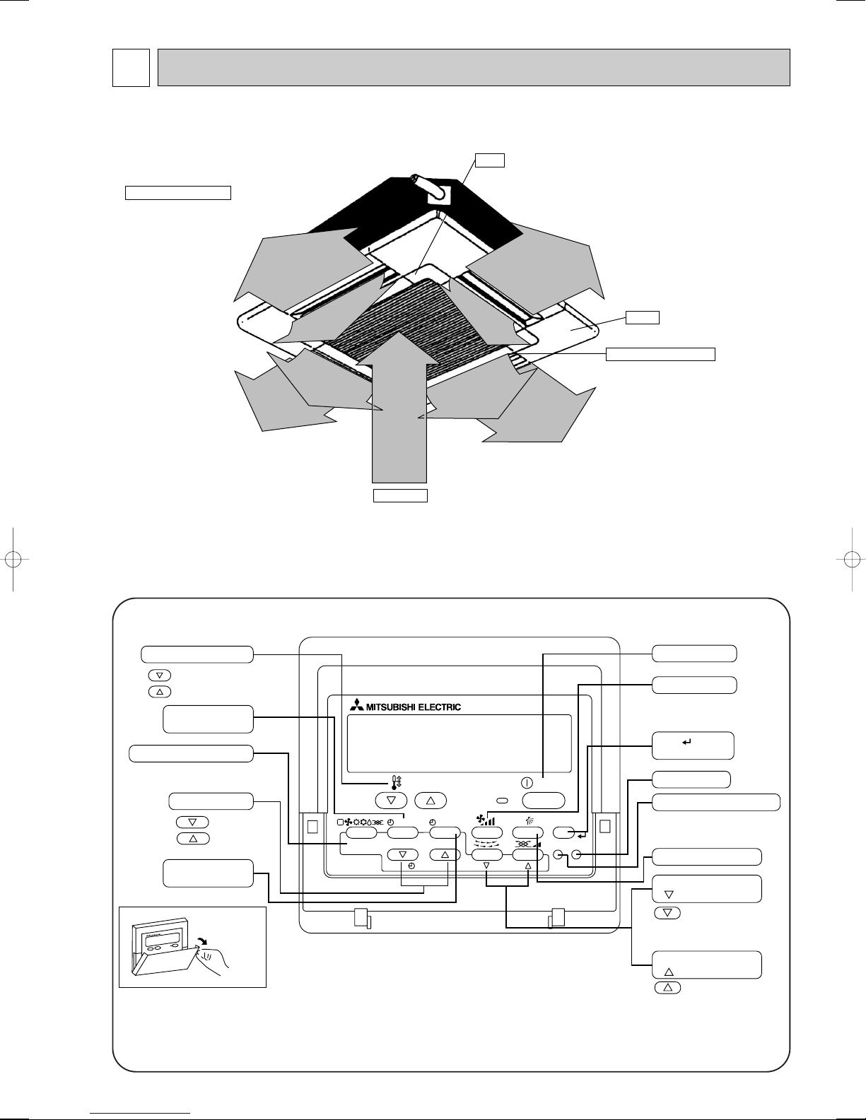
Auto Air Swing Vane
Disperses airflow up and
down and adjusts the angle
of airflow direction.
Grille
Filter
Removes dust and pollutants
from intake air
Horizontal Air Outlet
Sets airflow of horizontal automatically
during cooling or dehumidifying.
Air Intake
Intakes air from room.
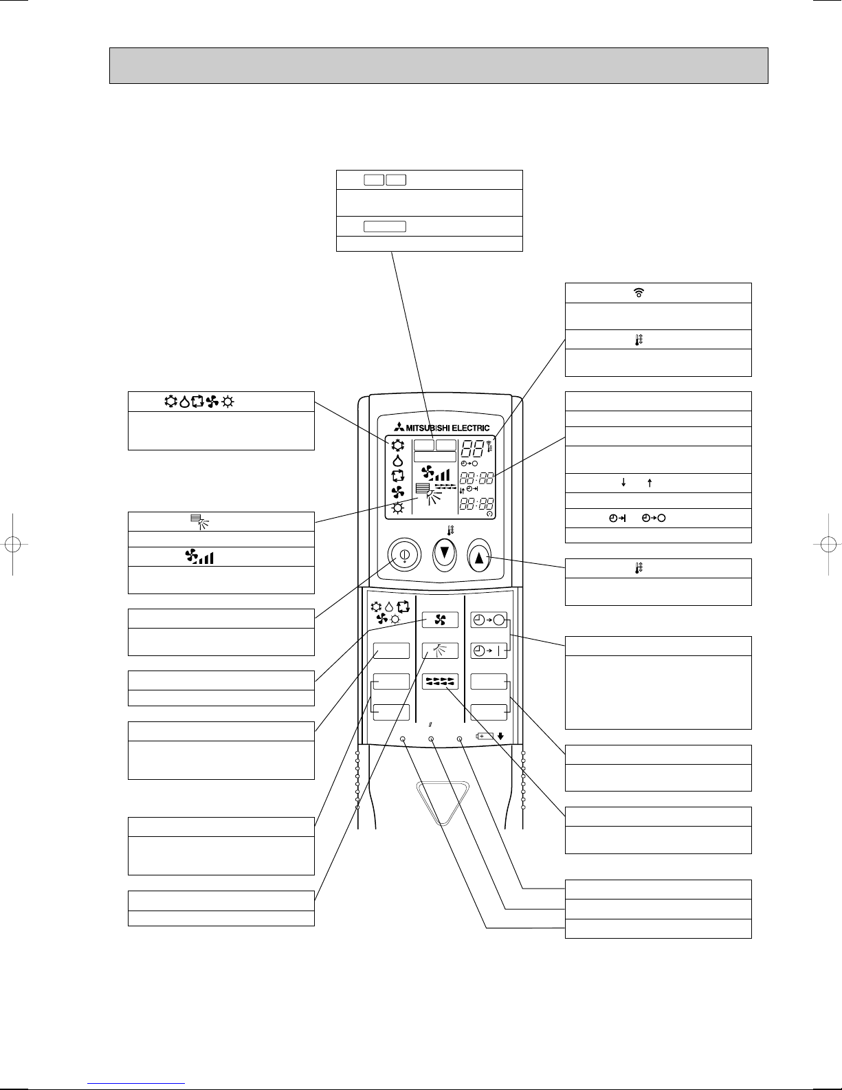
PART NAMES AND FUNCTIONS
● Indoor Unit
● Wired remote controller
On the controls are set, the same operation mode can be repeated by simply pressing the ON/OFF button.
● Operation buttons
3
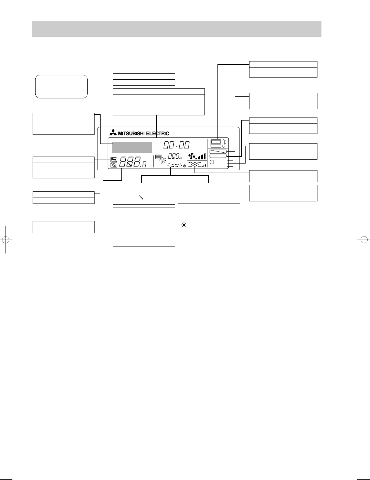
● Display
For purposes of this explanation,
all parts of the display are shown
as lit. During actual operation, only
the relevant items will be lit.
˚F˚C
˚F˚C
ERROR CODE
AFTER
TIMER
TIME SUN MON TUE WED THU FRI SAT
ON
OFF
Hr
AFTER
FILTER
FUNCTION
ONLY1Hr.
WEEKLY
SIMPLE
AUTO OFF
Identifies the current operation
Shows the operating mode, etc.
* Multilanguage display is sup-
ported.
“Centrally Controlled” indicator
Indicates that operation of the remote controller has been prohibited by a master controller.
“Timer Is Off” indicator
Indicates that the timer is off.
Temperature Setting
Shows the target temperature.
Day-of-Week
Shows the current day of the week.
Time/Timer Display
Shows the current time, unless the simple or Auto Off
timer is set.
If the simple or Auto Off timer is set, shows the time
remaining.
“Sensor” indication
Displayed when the remote controller
sensor is used.
“Locked” indicator
Indicates that remote controller buttons have been locked.
“Clean The Filter” indicator
Comes on when it is time to clean the
filter.
Timer indicators
The indicator comes on if the corresponding timer is set.
Up/Down Air Direction indicator
The indicator shows the direction of the outcoming airflow.
“One Hour Only” indicator
Displayed if the airflow is set to
weak and downward during COOL
or DRY mode. (Operation varies
according to model.)
The indicator goes off after one
hour, at which time the airflow direction also changes.
Room Temperature display
Shows the room temperature.
Louver display
Indicates the action of the swing
louver. Does not appear if the
louver is stationary.
(Power On indicator)
Indicates that the power is on.
Fan Speed indicator
Shows the selected fan speed.
Ventilation indicator
Appears when the unit is running in
Ventilation mode.
Caution
● Only the Power on indicator lights when the unit is stopped and power supplied to the unit.
● If you press a button for a feature that is not installed at the indoor unit, the remote controller will display the “Not Available”
message.
If you are using the remote controller to drive multiple indoor units, this message will appear only if he feature is not
present at the parent unit.
● When power is turned ON for the first time, it is normal that “PLEASE WAIT” is displayed on the room temperature indication (For max. 2minutes). Please wait until this “PLEASE WAIT” indication disappear then start the operation.
4
ON/OFF TEMP
FAN
VANE
TEST RUN
AUTO STOP
AUTO START
h
min
LOUVER
MODE
CHECK
RESETSET CLOCK
MODEL SELECT
NOT AVAILABLE
CHECK
TEST RUN
˚C
AMPM
AMPM
VANE CONTROL button
Used to change the air flow direction.
CLOCK button
RESET button
SET button
ON/OFF button
The unit is turned ON and OFF alternately
each time the button is pressed.
LOUVER button
This switch the horizontal fan motion ON
and OFF.
(Not available for this model.)
MODE SELECT button
Used to switch the operation mode between
cooling, drying, blowing, heating and auto
mode.
CHECK-TEST RUN button
Only press this button to perform an inspection check or test operation.
Do not use it for normal operation.
FAN SPEED SELECT button
Used to change the fan speed.
TIMER display
Displays when in timer operation or when
setting timer.
button
SET TEMPERATURE button sets any desired
room temperature.
CLOCK display
Displays the current time.
“ ” “ ” display
Displays the order of timer operation.
“ ” “ ” display
Displays whether timer is on or off.
w In case the outdoor unit is cool only type,
the heating mode is not available.
Buttons used to set the “hour and minute” of
the current time and timer settings.
h and min buttons
display
SET TEMP. display indicates desired temperature set.
display
FAN SPEED display indicates which fan
speed has been selected.
display
The vertical direction of air flow is indicated.
display
Blinks when model is selected.
display
Lights up while transmission to the indoor
unit is mode using switches.
display
CHECK&TEST RUN display indicates that
the unit is being checked or test-run.
display
OPERATION MODE display
Operation mode display indicates which operation mode is in effect.
TIMER CONTROL buttons
AUTO STOP (OFF timer): when this switch
is set, the air conditioner will be automatically stopped at the preset time.
AUTO START (ON timer): when this switch
is set, the air conditioner will be automatically started at the preset time.
MODEL SELECT
CHECK
TEST RUN
● Wireless remote controller
5
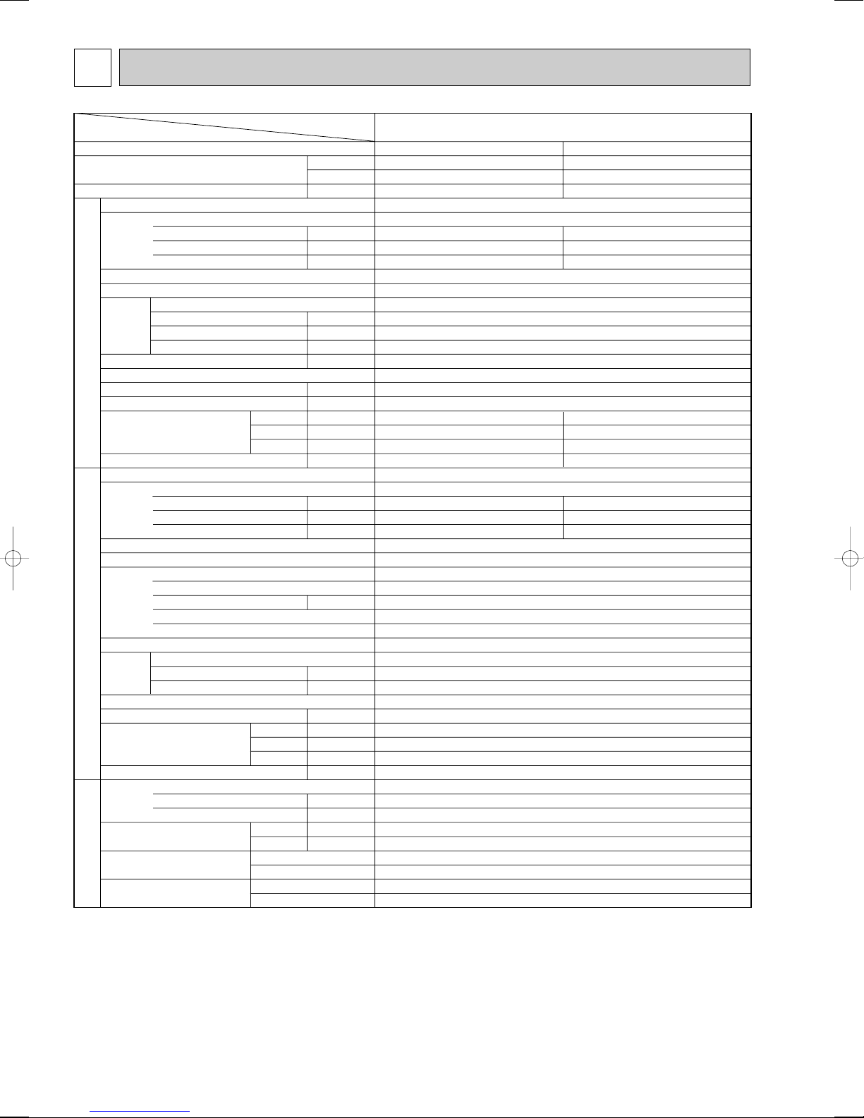
3
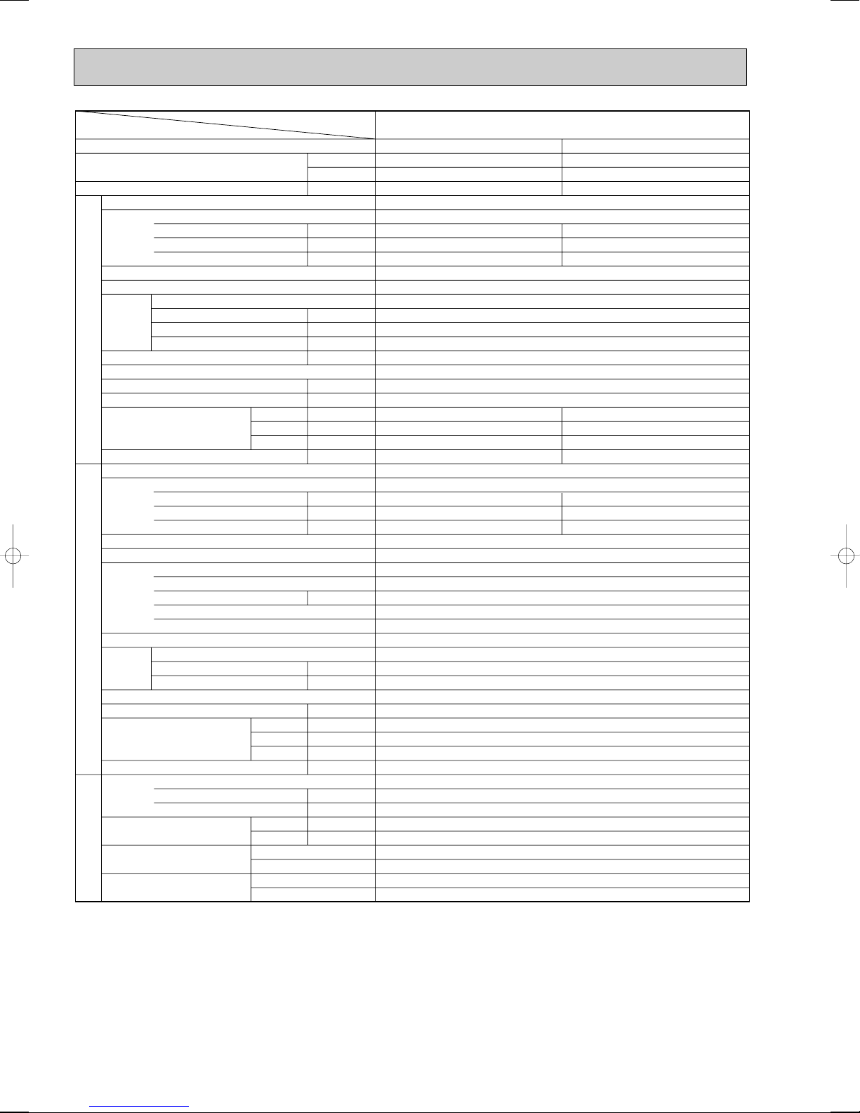
PLH-3AAK(H)
Cooling
26,300
7,700
3.32
0.17
0.81
1.00
UNIT : 840(33-1/6)
UNIT : 840(33-1/6)
UNIT : 258(10-1/8)
UNIT : 24(53) [26(57)]
3.15
13.82/5.16
58/37
Heating
28,700[35,800]
8,400[10,500]
3.11[5.21]
0.17[2.27]
0.81[9.47]
1.00[9.7]
PANEL : 950(37-3/8)
PANEL : 950(37-3/8)
PANEL : 30(1-3/16)
PANEL : 5(11)
2.94
12.89/4.81
58/37
PLH-3AAK(H)
Single, 50Hz, 220-240V
Grille : Munsell 0.70Y 8.59/0.97
Plate fin coil
Turbo fan (direct) x 1
0.07
15-20(530-705)
0(direct blow)
[2.1]
Remote controller & built-in
28-34
32(1-1/4)
PUH-3VKA.TH, PUH-3VKA
2.TH-A/PUH-3YKA.TH, PUH-3YKA1.TH-A
Single, 50Hz, 220-240V/3, 50Hz, 380-415V(4wires)
Munsell 5Y 7/1
Capillary tube
Hermetic
NH52VNHT/NH52YDAT
2.2/2.4
Line start
w1
Plate fin coil
Propeller (direct) x1
0.085
50(1764)
Reverse cycle
52
870(34-1/4)
295+24 (11-5/8 add 1)
850(33-1/4)
75(165)
R-22
3.2(7.1)
1.6<MS-32>
9.52 (3/8)
15.88(5/8)
Flared
Flared
Max. 50m
Max. 50m
Service Ref.
Power supply(phase, cycle,voltage)
External finish
Heat exchanger
Fan
Booster heater
Operation control & Thermostat
Noise level(Low-High)
Unit drain pipe O.D.
Dimensions
Weight
Service Ref.
Power supply (phase, cycle, voltage)
External finish
Refrigerant control
Compressor
Heat exchanger
Fan
Defrost method
Noise level
Dimensions
Weight
Refrigerant
Pipe size O.D.
Connection method
Between the indoor & outdoor units
Input
Running current
Starting current
Fan(drive) x No.
Fan motor output
Airflow(Low-High)
External static pressure
Input
Running current
Starting current
Model
Motor output
Starter type
Protection devices
Fan(drive) x No.
Fan motor output
Airflow
Charge
Oil<Model>
W
D
H
W
D
H
Liquid
Gas
Indoor side
Outdoor side
Height difference
Piping length
Function
Capacity
Total input
INDOOR UNITOUTDOOR UNIT
REFRIGERANT
PIPING
Item
Service Ref.
Btu/h
W
kW
kW
A
A
kW
K/ min (CFM)
Pa
kW
dB
mm(in.)
mm(in.)
mm(in.)
mm(in.)
kg(lbs)
kW
A
A
kW
kW
K/ min (CFM)
dB
mm(in.)
mm(in.)
mm(in.)
kg(lbs)
kg(lbs)
L
mm(in.)
mm(in.)
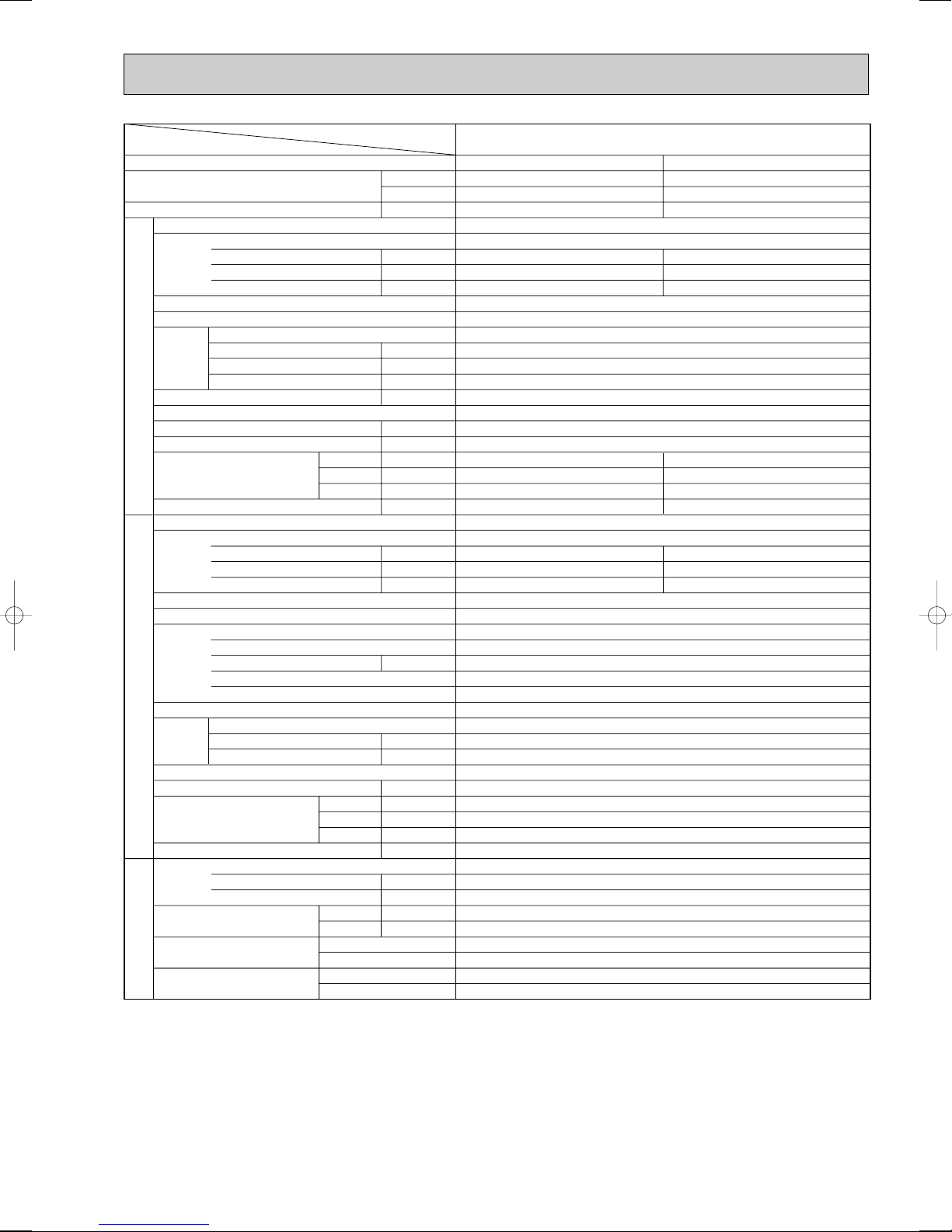
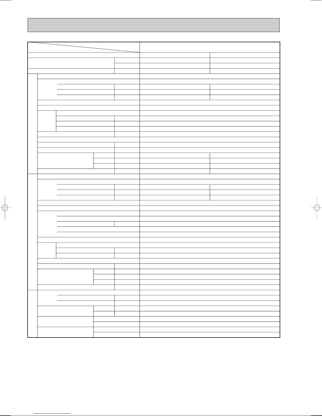
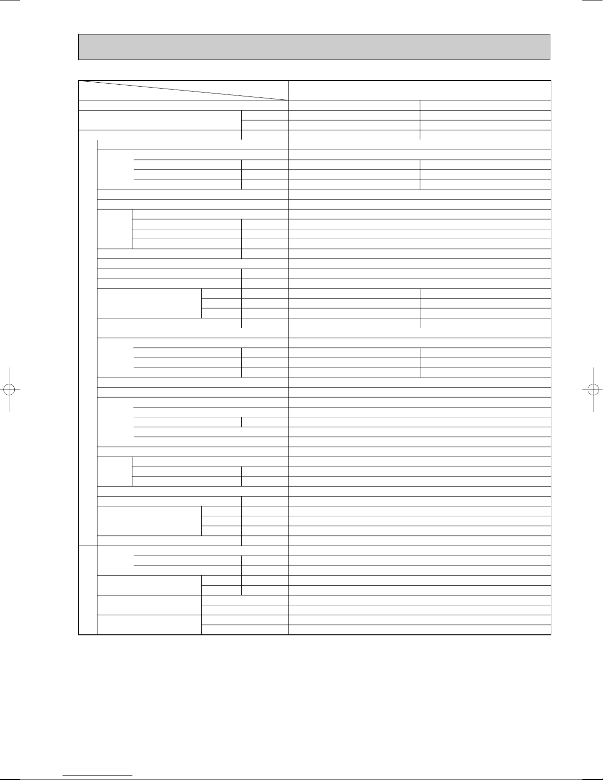
SPECIFICATIONS
w1 V …Internal Thermostat, HP switch
Y…Anti-phase protector, thermal relay, thermal switch, HP switch
Notes: Rating condition (ISO T1<JIS B8616>)
Cooling: Indoor : D.B. 27°C, W.B. 19°C
Outdoor : D.B. 35°C, W.B. 24°C
Heating: Indoor : D.B. 20°C
Outdoor : D.B. 7°C, W.B. 6°C
Refrigerant piping length(one way):5m(16ft)
6
Item
Function
Capacity
Total input
Service Ref.
Power supply(phase, cycle,voltage)
Input
Running current
Starting current
External finish
Heat exchanger
Fan
Booster heater
INDOOR UNITOUTDOOR UNIT
Operation control & Thermostat
Noise level(Low-High)
Unit drain pipe O.D.
Dimensions
Weight
Service Ref.
Power supply (phase, cycle, voltage)
External finish
Refrigerant control
Compressor
Heat exchanger
Fan
Defrost method
Noise level
Dimensions
Weight
Refrigerant
Pipe size O.D.
PIPING
Connection method
Fan(drive) x No.
Fan motor output
Airflow(Low-High)
External static pressure
Input
Running current
Starting current
Model
Motor output
Starter type
Protection devices
Fan(drive) x No.
Fan motor output
Airflow
Charge
Oil<Model>
REFRIGERANT
Between the indoor & outdoor units
Notes : w1.Rating condition (SSA 385)
Cooling: Indoor : D.B. 29°C, W.B. 19°C
Outdoor: D.B. 46°C, W.B. 24°C
Heating: Indoor : D.B. 21°C
Outdoor: D.B. 7°C, W.B. 6°C
w2.Rating condition (ISO T1<JIS 8616>)
Cooling: Indoor : D.B. 27°C, W.B. 19°C
Outdoor: D.B. 35°C, W.B. 24°C
Refrigerant piping length(one way):5m(16ft)
Service Ref.
K/ min (CFM)
W
D
H
K/ min (CFM)
W
D
H
Liquid
Gas
Indoor side
Outdoor side
Height difference
Piping length
Btu/h
W
kW
kW
A
A
kW
Pa
kW
dB
mm(in.)
mm(in.)
mm(in.)
mm(in.)
kg(lbs)
kW
A
A
kW
kW
dB
mm(in.)
mm(in.)
mm(in.)
kg(lbs)
kg(lbs)
L
mm(in.)
mm(in.)
Cooling w1/w2
23,200/27,300
6,800/8,000
4.29/3.68
0.16
0.77
1.00
Grille : Munsell 0.70Y 8.59/0.97
UNIT : 840(33-1/6)
UNIT : 840(33-1/6)
UNIT : 258(10-1/8)
UNIT : 24(53)
4.13/3.52
18.77/16.49
80
Internal thermostat, HP switch
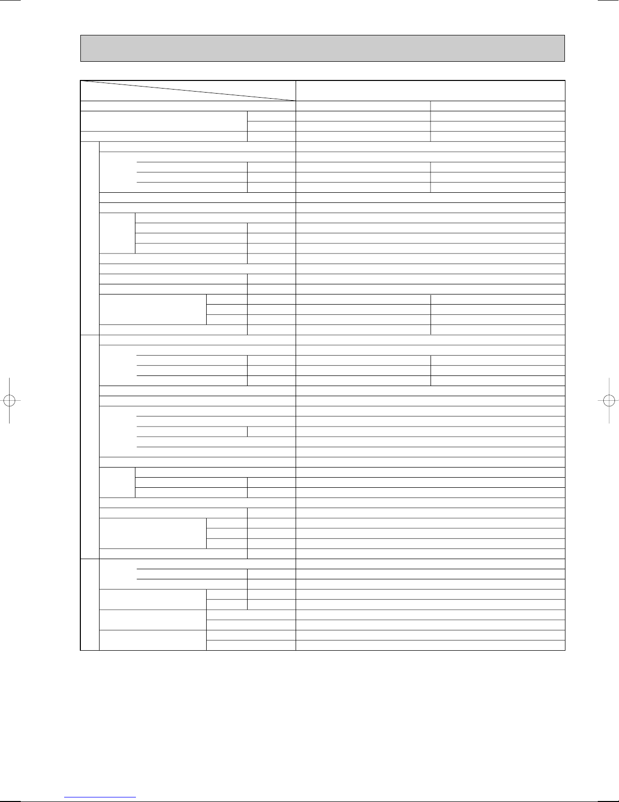
PLH-3AAK
Heating w1
31,700
9,300
3.49
PLH-3AAK
Single, 60Hz, 220V
0.16
0.77
1.00
Plate fin coil
Turbo fan (direct) x 1
0.07
15-20(530-705)
0(direct blow)
—
Remote controller & built-in
28-34
32(1-1/4)
PANEL : 950(37-3/8)
PANEL : 950(37-3/8)
PANEL : 30(1-3/16)
PANEL : 5(11)
PUH-3NKA.TH
Single, 60Hz, 220V
3.33
15.6
80
Munsell 5Y 7/1
Capillary tube
Hermetic
NHJ47NADT
2.2
Line start
Plate fin coil
Propeller (direct) x1
0.085
50(1764)
Reverse cycle
52
870(34-1/4)
295+24 (11-5/8 add 1)
850(33-1/4)
78(172)
R-22
3.2(7.1)
1.6<MS-32>
9.52 (3/8)
15.88(5/8)
Flared
Flared
Max. 50m
Max. 50m
7
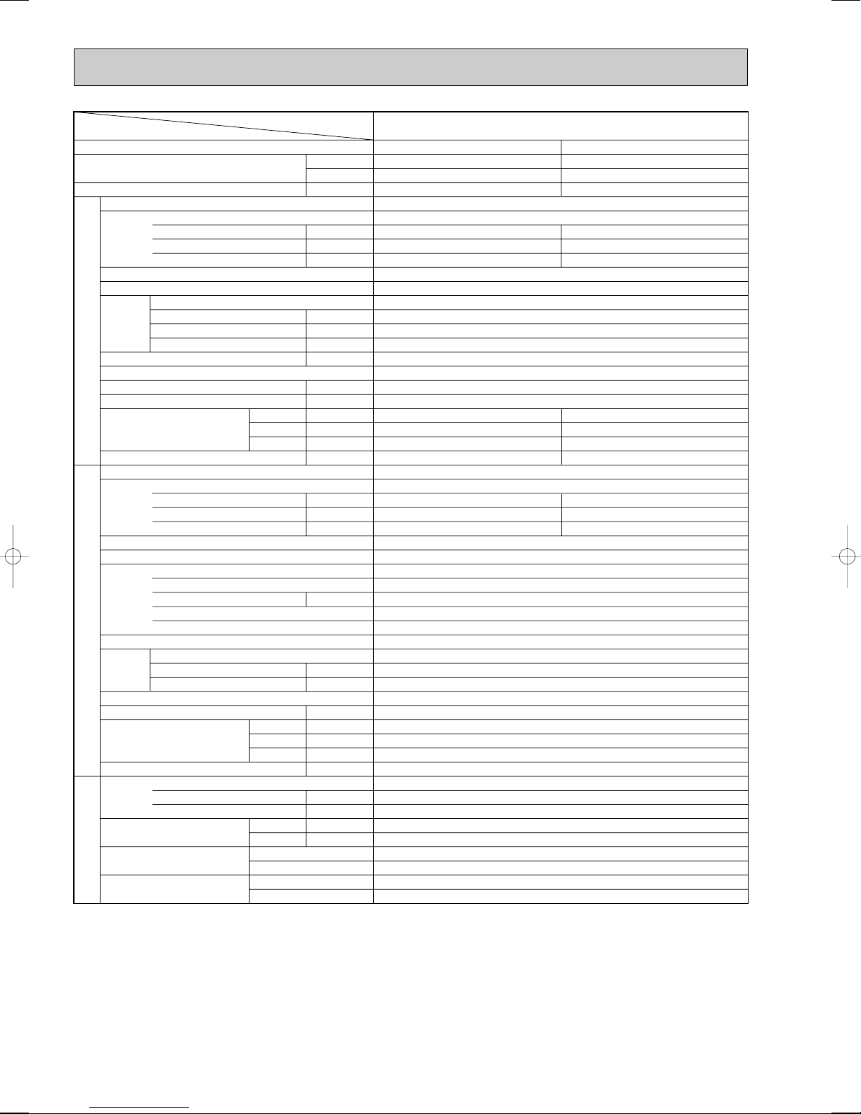
Cooling
33,100
9,700
3.46
0.26
1.25
2.0
UNIT : 840(33-1/6)
UNIT : 840(33-1/6)
UNIT : 298(11-3/4)
UNIT : 30(66)[32(71)]
3.20
5.24
40
Heating
35,500[44,400]
10,400[13,000]
3.45[6.05]
0.26[2.86]
1.25[11.93]
2.0[12.7]
PANEL : 950(37-3/8)
PANEL : 950(37-3/8)
PANEL : 30(1-3/16)
PANEL : 5(11)
3.19
5.22
40
Service Ref.
Power supply(phase, cycle,voltage)
External finish
Heat exchanger
Fan
Booster heater
Operation control & Thermostat
Noise level(Low-High)
Unit drain pipe O.D.
Dimensions
Weight
Service Ref.
Power supply (phase, cycle, voltage)
External finish
Refrigerant control
Compressor
Heat exchanger
Fan
Defrost method
Noise level
Dimensions
Weight
Refrigerant
Pipe size O.D.
Connection method
Between the indoor & outdoor units
Input
Running current
Starting current
Fan(drive) x No.
Fan motor output
Airflow(Low-High)
External static pressure
Input
Running current
Starting current
Model
Motor output
Starter type
Protection devices
Fan(drive) x No.
Fan motor output
Airflow
Charge
Oil<Model>
W
D
H
W
D
H
Liquid
Gas
Indoor side
Outdoor side
Height difference
Piping length
Function
Capacity
Total input
INDOOR UNITOUTDOOR UNIT
REFRIGERANT
PIPING
Item
Service Ref.
Btu/h
W
kW
kW
A
A
kW
K/ min (CFM)
Pa
kW
dB
mm(in.)
mm(in.)
mm(in.)
mm(in.)
kg(lbs)
kW
A
A
kW
kW
K/ min (CFM)
dB
mm(in.)
mm(in.)
mm(in.)
kg(lbs)
kg(lbs)
L
mm(in.)
mm(in.)
PLH-4AAK(H)
PLH-4AAK(H)
Single, 50Hz, 220-240V
Grille : Munsell 0.70Y 8.59/0.97
Plate fin coil
Turbo fan (direct) x 1
0.120
20-28(705-990)
0(direct blow)
[2.6]
Remote controller & built-in
33-41
32(1-1/4)
PUH-4YKSA.TH, PUH-4YKSA
1.TH-A
3, 50Hz, 380V-415V(4wire)
Munsell 5Y 7/1
Capillary tube
Hermetic
NH56YDAT
2.7
Line start
Anti-phase protector, Thermal relay, Thermal switch, HP switch
Plate fin coil
Propeller (direct) x2
0.065+0.065
95(3550)
Reverse cycle
54
870(34-1/4)
295+24(11-5/8 add 1)
1258(49-1/2)
94(207)
R-22
4.2(9.2)
1.6<MS-32>
9.52(3/8)
19.05(3/4)
Flared
Flared
Max. 50m
Max. 50m
Notes: Rating condition (ISO T1<JIS B8616>)
Cooling: Indoor : D.B. 27°C, W.B. 19°C
Heating: Indoor : D.B. 20°C
Refrigerant piping length(one way):5m(16ft)
Outdoor : D.B. 35°C, W.B. 24°C
Outdoor : D.B. 7°C, W.B. 6°C
8

Item
Function
Capacity
Total input
Service Ref.
Power supply(phase, cycle,voltage)
Input
Running current
Starting current
External finish
Heat exchanger
Fan
Booster heater
INDOOR UNITOUTDOOR UNIT
Operation control & Thermostat
Noise level(Low-High)
Unit drain pipe O.D.
Dimensions
Weight
Service Ref.
Power supply (phase, cycle, voltage)
External finish
Refrigerant control
Compressor
Heat exchanger
Fan
Defrost method
Noise level
Dimensions
Weight
Refrigerant
Pipe size O.D.
PIPING
Connection method
Fan(drive) x No.
Fan motor output
Airflow(Low-High)
External static pressure
Input
Running current
Starting current
Model
Motor output
Starter type
Protection devices
Fan(drive) x No.
Fan motor output
Airflow
Charge
Oil<Model>
REFRIGERANT
Between the indoor & outdoor units
Notes: w1.Rating condition (SSA 385)
Cooling: Indoor : D.B. 29°C, W.B. 19°C
Outdoor: D.B. 46°C, W.B. 24°C
Heating: Indoor : D.B. 21°C
Outdoor: D.B. 7°C, W.B. 6°C
w2.Rating condition (ISO T1<JIS 8616>)
Cooling: Indoor : D.B. 27°C, W.B. 19°C
Outdoor: D.B. 35°C, W.B. 24°C
Refrigerant piping length(one way):5m(16ft)
Service Ref.
K/ min (CFM)
W
D
H
K/ min (CFM)
W
D
H
Liquid
Gas
Indoor side
Outdoor side
Height difference
Piping length
Btu/h
W
kW
kW
A
A
kW
Pa
kW
dB
mm(in.)
mm(in.)
mm(in.)
mm(in.)
kg(lbs)
kW
A
A
kW
kW
dB
mm(in.)
mm(in.)
mm(in.)
kg(lbs)
kg(lbs)
L
mm(in.)
mm(in.)
PLH-4AAK
Cooling w1/w2
33,800/37,400
9,900/10,950
5.26/4.93
PLH-4AAK
Single, 60Hz, 220V
0.25
1.19
2.0
Grille : Munsell 0.70Y 8.59/0.97
Plate fin coil
Turbo fan (direct) x 1
0.120
20-28(705-990)
0(direct blow)
—
Remote controller & built-in
33-41
32(1-1/4)
UNIT : 840(33-1/6)
UNIT : 840(33-1/6)
UNIT : 298(11-3/4)
UNIT : 30(66)
PUH-4TKSA.TH
3, 60Hz, 220V
5.01/4.14
14.14/11.81
69
Munsell 5Y 7/1
Capillary tube
Hermetic
NHJ56TKAT
2.7
Line start
Anti-phase protector, Thermal relay, Thermal switch, HP switch
Plate fin coil
Propeller (direct) x2
0.065+0.065
95(3550)
Reverse cycle
55
870(34-1/4)
295+24(11-5/8 add 1)
1258(49-1/2)
94(207)
R-22
4.7(10.4)
1.6<MS-32>
9.52(3/8)
19.05(3/4)
Flared
Flared
Max. 50m
Max. 50m
Heating w1
41,300
12,100
4.21
0.25
1.19
2.0
PANEL : 950(37-3/8)
PANEL : 950(37-3/8)
PANEL : 30(1-3/16)
PANEL : 5(11)
3.96
11.3
69
9
Cooling
42,300
12,400
4.51
0.30
1.43
2.0
UNIT : 840(33-1/16)
UNIT : 840(33-1/16)
UNIT : 298(11-3/4)
UNIT : 30(66) [32(71)]
4.21
6.89
53
Heating
47,800[58,000]
14,000[17,000]
4.46[7.46]
0.30[3.30]
1.43[13.77]
2.0[14.3]
PANEL : 950(37-3/8)
PANEL : 950(37-3/8)
PANEL : 30(1-3/16)
PANEL : 5(11)
4.16
6.81
53
Service Ref.
Power supply(phase, cycle,voltage)
External finish
Heat exchanger
Fan
Booster heater
Operation control & Thermostat
Noise level(Low-High)
Unit drain pipe O.D.
Dimensions
Weight
Service Ref.
Power supply (phase, cycle, voltage)
External finish
Refrigerant control
Compressor
Heat exchanger
Fan
Defrost method
Noise level
Dimensions
Weight
Refrigerant
Pipe size O.D.
Connection method
Between the indoor & outdoor units
Input
Running current
Starting current
Fan(drive) x No.
Fan motor output
Airflow(Low-High)
External static pressure
Input
Running current
Starting current
Model
Motor output
Starter type
Protection devices
Fan(drive) x No.
Fan motor output
Airflow
Charge
Oil<Model>
W
D
H
W
D
H
Liquid
Gas
Indoor side
Outdoor side
Height difference
Piping length
Function
Capacity
Total input
INDOOR UNITOUTDOOR UNIT
REFRIGERANT
PIPING
Item
Service Ref.
Btu/h
W
kW
kW
A
A
kW
K/ min (CFM)
Pa
kW
dB
mm(in.)
mm(in.)
mm(in.)
mm(in.)
kg(lbs)
kW
A
A
kW
kW
K/ min (CFM)
dB
mm(in.)
mm(in.)
mm(in.)
kg(lbs)
kg(lbs)
L
mm(in.)
mm(in.)
PLH-5AAK(H)
PLH-5AAK(H)
Single, 50Hz, 220-240V
Grille : Munsell 0.70Y 8.59/0.97
Plate fin coil
Turbo fan (direct) x 1
0.120
22-30(775-1,060)
0(direct blow)
[3.0]
Remote controller & built-in
35-43
32(1-1/4)
PUH-5YKSA.TH, PUH-5YKSA
3.TH-A
3, 50Hz, 380-415V(4wire)
Munsell 5Y 7/1
Capillary tube
Hermetic
ZR61KC-TFD
3.5
Line start
Internal thermostat, Anti-phase protector, Thermal switch, HP switch
Plate fin coil
Propeller (direct) x2
0.085+0.085
95(3550)
Reverse cycle
55
970(38-3/16)
345+24(13-9/16 add 1)
1258(49-1/2)
114(251)
R-22
5.4(11.9)
2.130<SONTEX-200LT>
9.52(3/8)
19.05(3/4)
Flared
Flared
Max. 50m
Max. 50m
Notes: Rating condition (ISO T1<JIS B8616>)
Cooling: Indoor : D.B. 27°C, W.B. 19°C
Outdoor : D.B. 35°C, W.B. 24°C
Heating: Indoor : D.B. 20°C
Outdoor : D.B. 7°C, W.B. 6°C
Refrigerant piping length(one way):5m(16ft)
10
Item
Function
Capacity
Total input
Service Ref.
Power supply(phase, cycle,voltage)
Input
Running current
Starting current
External finish
Heat exchanger
Fan
Booster heater
INDOOR UNITOUTDOOR UNIT
Operation control & Thermostat
Noise level(Low-High)
Unit drain pipe O.D.
Dimensions
Weight
Service Ref.
Power supply (phase, cycle, voltage)
External finish
Refrigerant control
Compressor
Heat exchanger
Fan
Defrost method
Noise level
Dimensions
Weight
Refrigerant
Pipe size O.D.
PIPING
Connection method
Fan(drive) x No.
Fan motor output
Airflow(Low-High)
External static pressure
Input
Running current
Starting current
Model
Motor output
Starter type
Protection devices
Fan(drive) x No.
Fan motor output
Airflow
Charge
Oil<Model>
REFRIGERANT
Between the indoor & outdoor units
Notes: w1.Rating condition (SSA 385)
Cooling: Indoor : D.B. 29°C, W.B. 19°C
Outdoor: D.B. 46°C, W.B. 24°C
Heating: Indoor : D.B. 21°C
Outdoor: D.B. 7°C, W.B. 6°C
w2.Rating condition (ISO T1<JIS 8616>)
Cooling: Indoor : D.B. 27°C, W.B. 19°C
Outdoor: D.B. 35°C, W.B. 24°C
Refrigerant piping length(one way):5m(16ft)
Service Ref.
K/ min (CFM)
W
D
H
K/ min (CFM)
W
D
H
Liquid
Gas
Indoor side
Outdoor side
Height difference
Piping length
Btu/h
W
kW
kW
A
A
kW
Pa
kW
dB
mm(in.)
mm(in.)
mm(in.)
mm(in.)
kg(lbs)
kW
A
A
kW
kW
dB
mm(in.)
mm(in.)
mm(in.)
kg(lbs)
kg(lbs)
L
mm(in.)
mm(in.)
PLH-5AAK
Cooling w1/w2
37,500/44,400
11,000/13,000
6.78/5.58
PLH-5AAK
Single, 60Hz, 220V
0.26
1.24
2.0
Grille : Munsell 0.70Y 8.59/0.97
Plate fin coil
Turbo fan (direct) x 1
0.120
22-30(775-1,060)
0(direct blow)
—
Remote controller & built-in
35-43
32(1-1/4)
UNIT : 840(33-1/16)
UNIT : 840(33-1/16)
UNIT : 298(11-3/4)
UNIT : 30(66)
PUH-5TKSA.TH
3, 60Hz, 220V
6.52/5.32
19.23/16.23
135
Munsell 5Y 7/1
Capillary tube
Hermetic
ZR61KC-TF5
3.5
Line start
Internal thermostat, Anti-phase protector, Thermal switch, HP switch
Plate fin coil
Propeller (direct) x2
0.100+0.100
100(3500)
Reverse cycle
55
970(38-3/16)
345+24(13-9/16 add 1)
1258(49-1/2)
114(251)
R-22
5.4(11.9)
2.13<SONTEX-200LT>
9.52(3/8)
19.05(3/4)
Flared
Flared
Max. 50m
Max. 50m
Heating w1
56,300
16,500
6.02
0.26
1.24
2.0
PANEL : 950(37-3/8)
PANEL : 950(37-3/8)
PANEL : 30(1-3/16)
PANEL :5(11)
5.76
17.38
135
11
PLH-6AAK(H)
Cooling
47,800
14,000
5.07
0.34
1.64
2.0
UNIT : 840(33-1/16)
UNIT : 840(33-1/16)
UNIT : 298(11-3/4)
UNIT : 32(71)[34(75)]
4.73
7.74
74
Heating
54,900[65,200]
16,100[19,100]
4.92[7.92]
0.34[3.34]
1.64[13.94]
2.0[14.3]
PANEL : 950(37-3/8)
PANEL : 950(37-3/8)
PANEL : 30(1-3/16)
PANEL : 5(11)
4.58
7.50
74
Service Ref.
Power supply(phase, cycle,voltage)
External finish
Heat exchanger
Fan
Booster heater
Operation control & Thermostat
Noise level(Low-High)
Unit drain pipe O.D.
Dimensions
Weight
Service Ref.
Power supply (phase, cycle, voltage)
External finish
Refrigerant control
Compressor
Heat exchanger
Fan
Defrost method
Noise level
Dimensions
Weight
Refrigerant
Pipe size O.D.
Connection method
Between the indoor & outdoor units
Input
Running current
Starting current
Fan(drive) x No.
Fan motor output
Airflow(Low-High)
External static pressure
Input
Running current
Starting current
Model
Motor output
Starter type
Protection devices
Fan(drive) x No.
Fan motor output
Airflow
Charge
Oil<Model>
W
D
H
W
D
H
Liquid
Gas
Indoor side
Outdoor side
Height difference
Piping length
Function
Capacity
Total input
INDOOR UNITOUTDOOR UNIT
REFRIGERANT
PIPING
Item
Service Ref.
Btu/h
W
kW
kW
A
A
kW
K/ min (CFM)
Pa
kW
dB
mm(in.)
mm(in.)
mm(in.)
mm(in.)
kg(lbs)
kW
A
A
kW
kW
K/ min (CFM)
dB
mm(in.)
mm(in.)
mm(in.)
kg(lbs)
kg(lbs)
L
mm(in.)
mm(in.)
PLH-6AAK(H)
Single, 50Hz, 220-240V
Grille : Munsell 0.70Y 8.59/0.97
Plate fin coil
Turbo fan (direct) x 1
0.120
22-30(775-1,060)
0(direct blow)
[3.0]
Remote controller & built-in
37-45
32(1-1/4)
PUH-6YKSA.TH, PUH-6YKSA
3.TH-A
3, 50Hz, 380-415V(4wire)
Munsell 5Y 7/1
Capillary tube
Hermetic
ZR68KC-TFD
4.0
Line start
Internal thermostat, Anti-phase protector, Thermal switch, HP switch
Plate fin coil
Propeller (direct) x2
0.10+0.10
100(3530)
Reverse cycle
56
970(38-3/16)
345+24(13-9/16 add 1)
1258(49-1/2)
117(258)
R-22
5.0(11.0)
1.774<SONTEX-200LT>
9.52(3/8)
19.05(3/4)
Flared
Flared
Max. 50m
Max. 50m
Notes: Rating condition (ISO T1<JIS B8616>)
Cooling: Indoor : D.B. 27°C, W.B. 19°C
Outdoor : D.B. 35°C, W.B. 24°C
Heating: Indoor : D.B. 20°C
Outdoor : D.B. 7°C, W.B. 6°C
Refrigerant piping length(one way):5m(16ft)
12
PLH-6AAK
Cooling w1/w2
45,700/51,900
13,400/15,200
7.32/6.15
0.28
1.34
2.0
UNIT : 840(33-1/16)
UNIT : 840(33-1/16)
UNIT : 298(11-3/4)
UNIT : 32(71)
7.04/5.87
20.3/17.31
140
Heating w1
59,700
17,500
6.7
0.28
1.34
2.0
PANEL : 950(37-3/8)
PANEL : 950(37-3/8)
PANEL : 30(1-3/16)
PANEL :5(11)
6.42
18.51
140
Service Ref.
Power supply(phase, cycle,voltage)
External finish
Heat exchanger
Fan
Booster heater
Operation control & Thermostat
Noise level(Low-High)
Unit drain pipe O.D.
Dimensions
Weight
Service Ref.
Power supply (phase, cycle, voltage)
External finish
Refrigerant control
Compressor
Heat exchanger
Fan
Defrost method
Noise level
Dimensions
Weight
Refrigerant
Pipe size O.D.
Connection method
Between the indoor & outdoor units
Input
Running current
Starting current
Fan(drive) x No.
Fan motor output
Airflow(Low-High)
External static pressure
Input
Running current
Starting current
Model
Motor output
Starter type
Protection devices
Fan(drive) x No.
Fan motor output
Airflow
Charge
Oil<Model>
W
D
H
W
D
H
Liquid
Gas
Indoor side
Outdoor side
Height difference
Piping length
Function
Capacity
Total input
INDOOR UNITOUTDOOR UNIT
REFRIGERANT
PIPING
Item
Service Ref.
Btu/h
W
kW
kW
A
A
kW
K/ min (CFM)
Pa
kW
dB
mm(in.)
mm(in.)
mm(in.)
mm(in.)
kg(lbs)
kW
A
A
kW
kW
K/ min (CFM)
dB
mm(in.)
mm(in.)
mm(in.)
kg(lbs)
kg(lbs)
L
mm(in.)
mm(in.)
PLH-6AAK
Single, 60Hz, 220V
Grille : Munsell 0.70Y 8.59/0.97
Plate fin coil
Turbo fan (direct) x 1
0.120
22-30(775-1,060)
0(direct blow)
—
Remote controller & built-in
37-45
32(1-1/4)
PUH-6TKSA.TH
3, 60Hz, 220V
Munsell 5Y 7/1
Capillary tube
Hermetic
ZR68KC-TF5
4.0
Line start
Internal thermostat, Anti-phase protector, Thermal switch, HP switch
Plate fin coil
Propeller (direct) x2
0.10+0.10
100(3530)
Reverse cycle
56
970(38-3/16)
345+24(13-9/16 add 1)
1258(49-1/2)
117(258)
R-22
5.0(11.0)
1.774<SONTEX-200LT>
9.52(3/8)
19.05(3/4)
Flared
Flared
Max. 50m
Max. 50m
Notes: w1.Rating condition (SSA 385)
Cooling: Indoor : D.B. 29°C, W.B. 19°C
Outdoor: D.B. 46°C, W.B. 24°C
Heating: Indoor : D.B. 21°C
Outdoor: D.B. 7°C, W.B. 6°C
w2.Rating condition (ISO T1<JIS 8616>)
Cooling: Indoor : D.B. 27°C, W.B. 19°C
Outdoor: D.B. 35°C, W.B. 24°C
Refrigerant piping length(one way):5m(16ft)
13
4
Outdoor intake air D.B.(°C)
20 25 30
Indoor
Intake air
D.B.(°C)
Indoor
Intake air
W.B.(°C)
20
20
22
22
22
24
24
24
24
26
26
26
26
27
27
27
27
28
28
28
28
30
30
30
30
32
32
32
32
16
18
16
18
20
16
18
20
22
16
18
20
22
16
18
20
22
16
18
20
22
16
18
20
22
16
18
20
22
7768
8271
7768
8271
8779
7768
8271
8779
9293
7768
8271
8779
9293
7768
8271
8779
9293
7768
8271
8779
9293
7768
8271
8779
9293
7768
8271
8779
9293
CA SHC SHF P.C. CA SHC SHF P.C. CA SHC SHF P.C.
4972
4301
5593
4963
4214
6214
5624
4916
4089
6836
6286
5619
4832
7147
6617
5970
5204
7457
6948
6321
5576
7768
7609
7023
6319
7768
8271
7726
7063
0.64
0.52
0.72
0.60
0.48
0.80
0.68
0.56
0.44
0.88
0.76
0.64
0.52
0.92
0.80
0.68
0.56
0.96
0.84
0.72
0.60
1.00
0.92
0.80
0.68
1.00
1.00
0.88
0.76
0.64
0.52
0.72
0.60
0.48
0.80
0.68
0.56
0.44
0.88
0.76
0.64
0.52
0.92
0.80
0.68
0.56
0.96
0.84
0.72
0.60
1.00
0.92
0.80
0.68
1.00
1.00
0.88
0.76
0.64
0.52
0.72
0.60
0.48
0.80
0.68
0.56
0.44
0.88
0.76
0.64
0.52
0.92
0.80
0.64
0.52
0.96
0.84
0.72
0.60
1.00
0.92
0.80
0.68
1.00
1.00
0.88
0.76
2.66
2.71
2.66
2.71
2.77
2.66
2.71
2.77
2.82
2.66
2.71
2.77
2.82
2.66
2.71
2.77
2.82
2.66
2.71
2.77
2.82
2.66
2.71
2.77
2.82
2.66
2.71
2.77
2.82
7555
8053
7555
8053
8573
7555
8053
8573
9115
7555
8053
8573
9115
7555
8053
8573
9115
7555
8053
8573
9115
7555
8053
8573
9115
7555
8053
8573
9115
4835
4188
5440
4832
4115
6044
5476
4801
4011
6649
6120
5487
4740
6951
6443
5830
5104
7253
6765
6173
5469
7555
7409
6858
6198
7555
8053
7544
6927
2.77
2.83
2.77
2.83
2.89
2.77
2.83
2.89
2.94
2.77
2.83
2.89
2.94
2.77
2.83
2.89
2.94
2.77
2.83
2.89
2.94
2.77
2.83
2.89
2.94
2.77
2.83
2.89
2.94
7278
7760
7278
7760
8267
7278
7760
8267
8799
7278
7760
8267
8799
7278
7760
8267
8799
7278
7760
8267
8799
7278
7760
8267
8799
7278
7760
8267
8799
4658
4035
5240
4656
3968
5822
5277
4630
3872
6404
5898
5291
4576
6696
6208
5622
4928
6987
6518
5952
5279
7278
7139
6614
5983
7278
7760
7275
6687
2.99
3.06
2.99
3.06
3.12
2.99
3.06
3.12
3.19
2.99
3.06
3.12
3.19
2.99
3.06
3.12
3.19
2.99
3.06
3.12
3.19
2.99
3.06
3.12
3.19
2.99
3.06
3.12
3.19
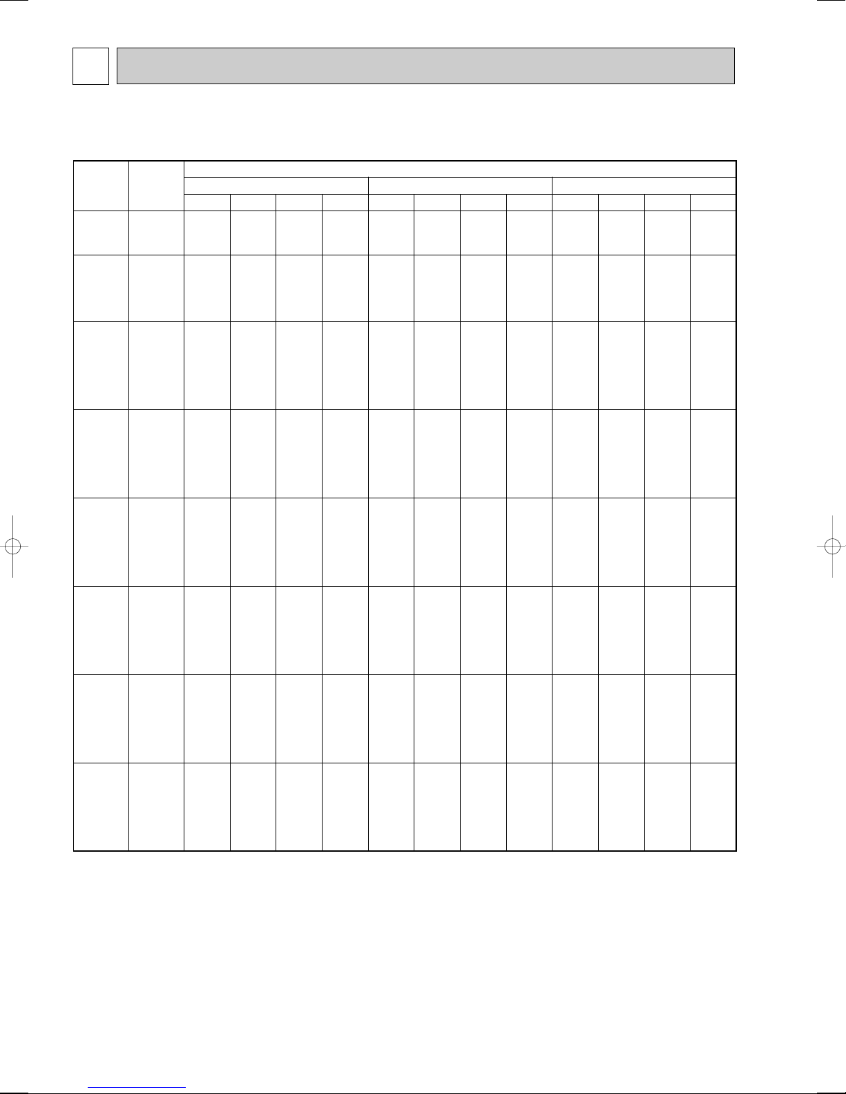
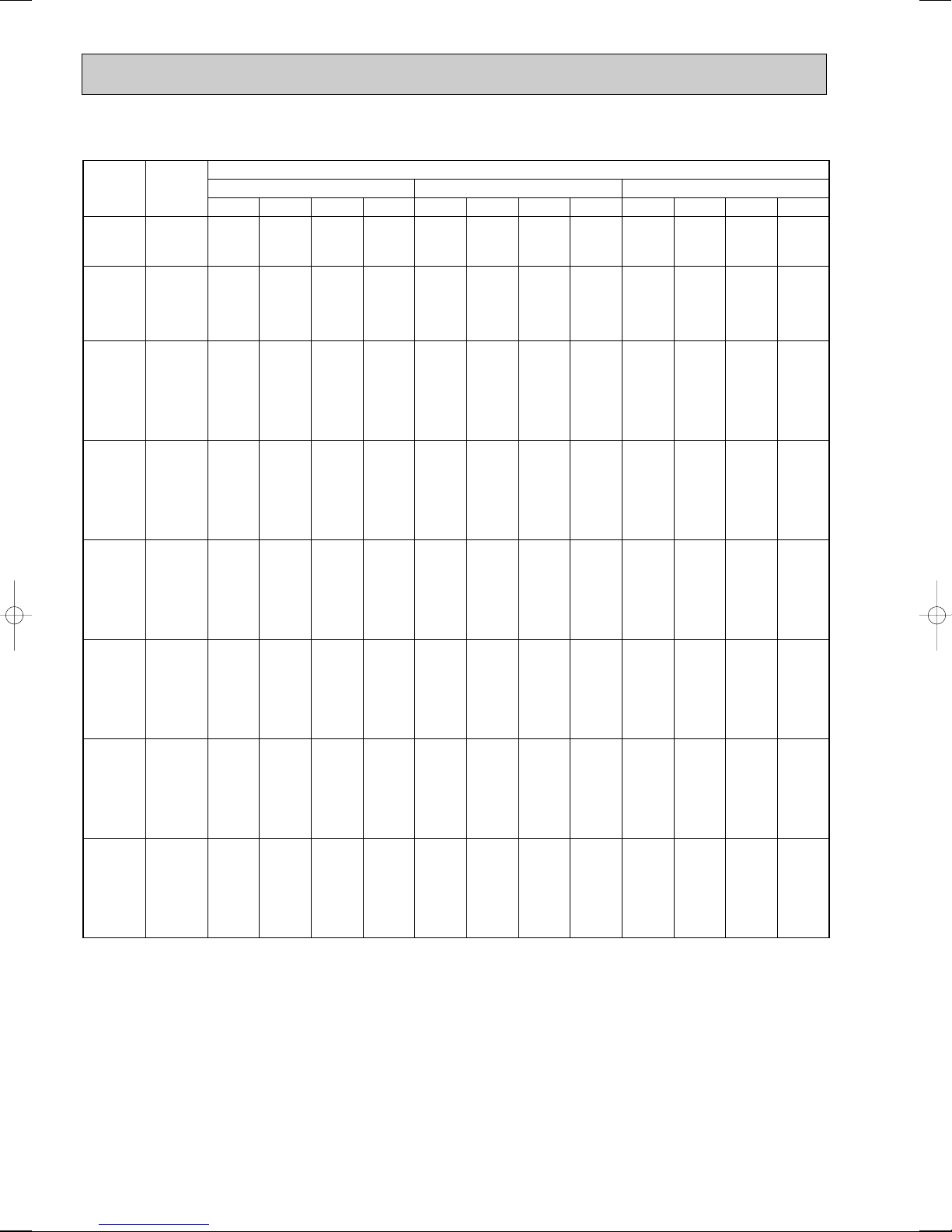
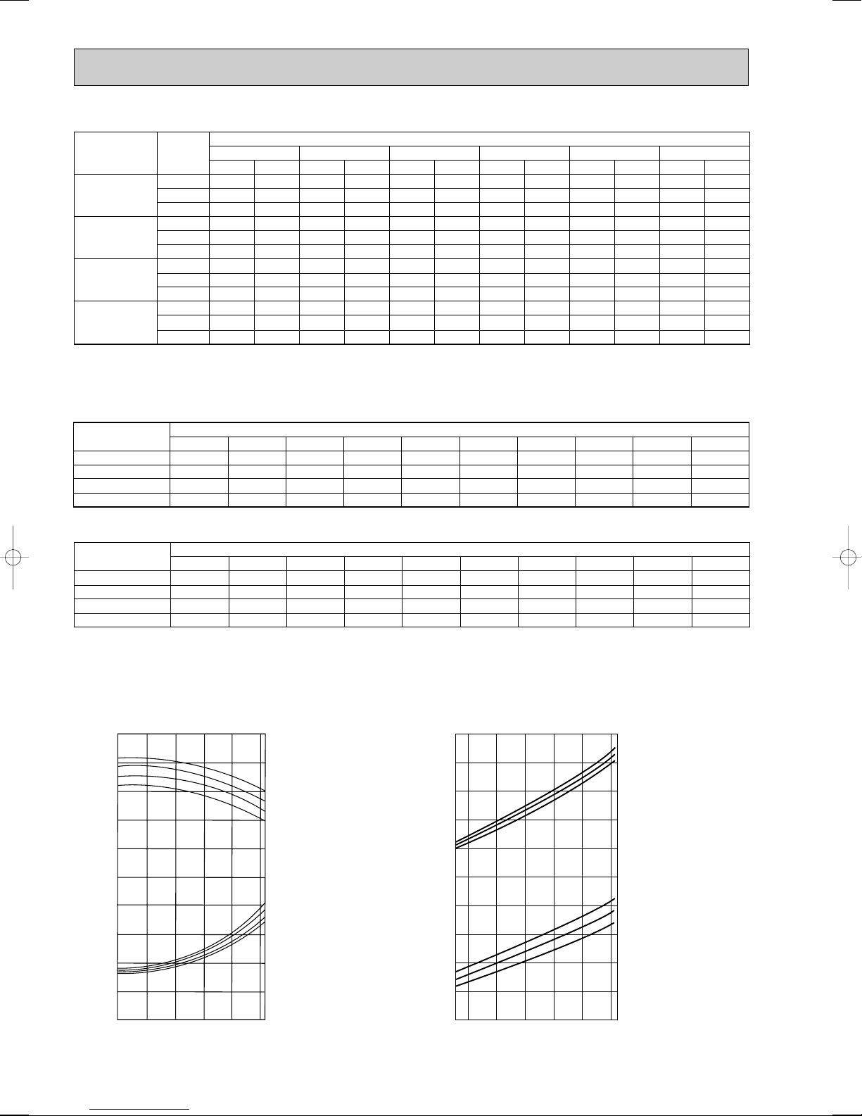
DATA
1. PERFORMANCE DATA [50Hz]
1) COOLING CAPACITY(1)
PLH-3AAK(H)
CA : Capacity (W) SHC : Sensible heat capacity (W)
P.C. : Power consumption (kW) SHF : Sensible heat factor
14
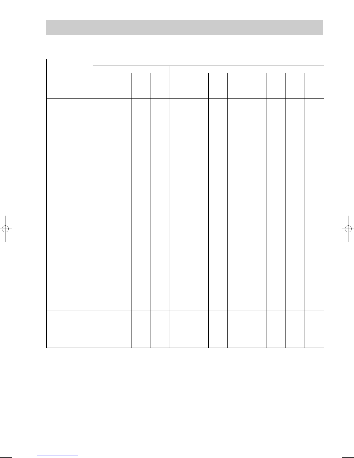
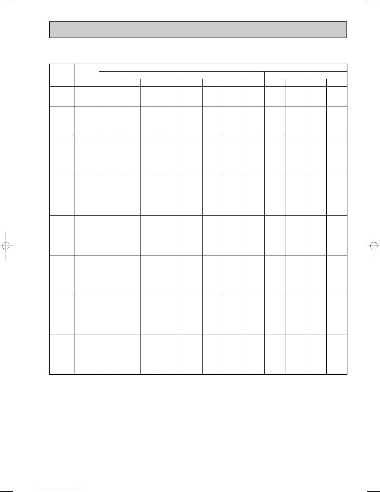
COOLING CAPACITY(2)
Outdoor intake air D.B.(°C)
35 40 45
Indoor
Intake air
D.B.(°C)
Indoor
Intake air
W.B.(°C)
20
20
22
22
22
24
24
24
24
26
26
26
26
27
27
27
27
28
28
28
28
30
30
30
30
32
32
32
32
16
18
16
18
20
16
18
20
22
16
18
20
22
16
18
20
22
16
18
20
22
16
18
20
22
16
18
20
22
6983
7452
6983
7452
7948
6983
7452
7948
8470
6983
7452
7948
8470
6983
7452
7948
8470
6983
7452
7948
8470
6983
7452
7948
8470
6983
7452
7948
8470
CA SHC SHF P.C. CA SHC SHF P.C. CA SHC SHF P.C.
4469
3875
5028
4471
3815
5586
5067
4451
3727
6145
5664
5087
4405
6424
5962
5405
4743
6704
6260
5722
5082
6983
6856
6358
5760
6983
7452
6994
6437
0.64
0.52
0.72
0.60
0.48
0.80
0.68
0.56
0.44
0.88
0.76
0.64
0.52
0.92
0.80
0.68
0.56
0.96
0.84
0.72
0.60
1.00
0.92
0.80
0.68
1.00
1.00
0.88
0.76
0.64
0.52
0.72
0.60
0.48
0.80
0.68
0.56
0.44
0.88
0.76
0.64
0.52
0.92
0.80
0.68
0.56
0.96
0.84
0.72
0.60
1.00
0.92
0.80
0.68
1.00
1.00
0.88
0.76
0.64
0.52
0.72
0.60
0.48
0.80
0.68
0.56
0.44
0.88
0.76
0.64
0.52
0.92
0.80
0.64
0.52
0.96
0.84
0.72
0.60
1.00
0.92
0.80
0.68
1.00
1.00
0.88
0.76
3.20
3.28
3.20
3.28
3.36
3.20
3.28
3.36
3.44
3.20
3.28
3.36
3.44
3.20
3.28
3.36
3.44
3.20
3.28
3.36
3.44
3.20
3.28
3.36
3.44
3.20
3.28
3.36
3.44
6671
7130
6671
7130
7616
6671
7130
7616
8128
6671
7130
7616
8128
6671
7130
7616
8128
6671
7130
7616
8128
6671
7130
7616
8128
6671
7130
7616
8128
4269
3708
4803
4278
3656
5337
4848
4265
3576
5870
5419
4874
4227
6137
5704
5179
4552
6404
5989
5483
4877
6671
6559
6093
5527
6671
7130
6702
6178
3.42
3.51
3.42
3.51
3.60
3.42
3.51
3.60
3.70
3.42
3.51
3.60
3.70
3.42
3.51
3.60
3.70
3.42
3.51
3.60
3.70
3.42
3.51
3.60
3.70
3.42
3.51
3.60
3.70
6342
6793
6342
6793
7270
6342
6793
7270
7773
6342
6793
7270
7773
6342
6793
7270
7773
6342
6793
7270
7773
6342
6793
7270
7773
6342
6793
7270
7773
4059
3532
4566
4076
3490
5073
4619
4071
3420
5581
5163
4653
4042
5834
5434
4944
4353
6088
5706
5235
4664
6342
6250
5816
5286
6342
6793
6398
5908
3.64
3.73
3.64
3.73
3.84
3.64
3.73
3.84
3.97
3.64
3.73
3.84
3.97
3.64
3.73
3.84
3.97
3.64
3.73
3.84
3.97
3.64
3.73
3.84
3.97
3.64
3.73
3.84
3.97
PLH-3AAK(H)
CA : Capacity (W) SHC : Sensible heat capacity (W)
P.C. : Power consumption (kW) SHF : Sensible heat factor
15
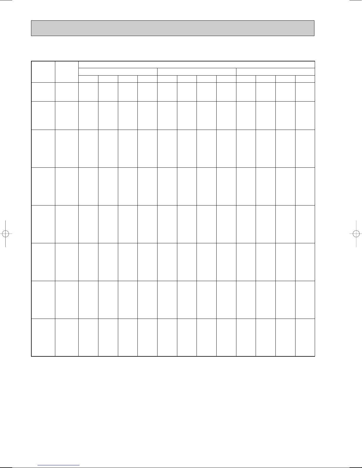
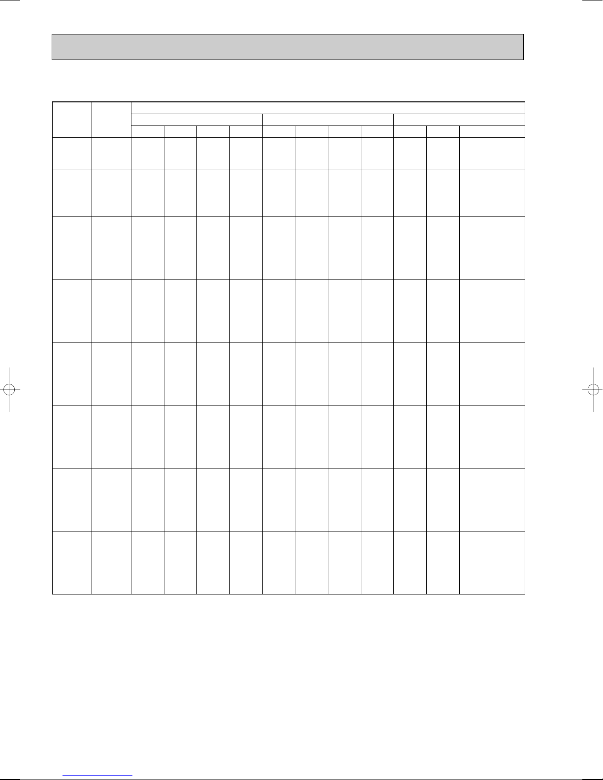
COOLING CAPACITY(3)
Outdoor intake air D.B.(°C)
20 25 30
Indoor
Intake air
D.B.(°C)
Indoor
Intake air
W.B.(°C)
20
20
22
22
22
24
24
24
24
26
26
26
26
27
27
27
27
28
28
28
28
30
30
30
30
32
32
32
32
16
18
16
18
20
16
18
20
22
16
18
20
22
16
18
20
22
16
18
20
22
16
18
20
22
16
18
20
22
9786
10419
9786
10419
11060
9786
10419
11060
11707
9786
10419
11060
11707
9786
10419
11060
11707
9786
10419
11060
11707
9786
10419
11060
11707
9786
10419
11060
11707
CA SHC SHF P.C. CA SHC SHF P.C. CA SHC SHF P.C.
6752
5939
7535
6773
5862
8318
7606
6746
5736
9101
8440
7631
6673
9492
8856
8073
7141
9786
9273
8516
7609
9786
10107
9401
8546
9786
10419
10285
9483
0.69
0.57
0.77
0.65
0.53
0.85
0.73
0.61
0.49
0.93
0.81
0.69
0.57
0.97
0.85
0.73
0.61
1.00
0.89
0.77
0.65
1.00
0.97
0.85
0.73
1.00
1.00
0.93
0.81
0.69
0.57
0.77
0.65
0.53
0.85
0.73
0.61
0.49
0.93
0.81
0.69
0.57
0.97
0.85
0.73
0.61
1.00
0.89
0.77
0.65
1.00
0.97
0.85
0.73
1.00
1.00
0.93
0.81
0.69
0.57
0.77
0.65
0.53
0.85
0.73
0.61
0.49
0.93
0.81
0.69
0.57
0.97
0.85
0.73
0.61
1.00
0.89
0.77
0.65
1.00
0.97
0.85
0.73
1.00
1.00
0.93
0.81
2.77
2.83
2.77
2.83
2.88
2.77
2.83
2.88
2.94
2.77
2.83
2.88
2.94
2.77
2.83
2.88
2.94
2.77
2.83
2.88
2.94
2.77
2.83
2.88
2.94
2.77
2.83
2.88
2.94
9518
10145
9518
10145
10800
9518
10145
10800
11482
9518
10145
10800
11482
9518
10145
10800
11482
9518
10145
10800
11482
9518
10145
10800
11482
9518
10145
10800
11482
6567
5783
7329
6594
5724
8090
7406
6588
5626
8852
8217
7452
6545
9232
8623
7884
7004
9518
9029
8316
7464
9518
9841
9180
8382
9518
10145
10044
9301
2.89
2.95
2.89
2.95
3.01
2.89
2.95
3.01
3.07
2.89
2.95
3.01
3.07
2.89
2.95
3.01
3.07
2.89
2.95
3.01
3.07
2.89
2.95
3.01
3.07
2.89
2.95
3.01
3.07
9168
9775
9168
9775
10414
9168
9775
10414
11085
9168
9775
10414
11085
9168
9775
10414
11085
9168
9775
10414
11085
9168
9775
10414
11085
9168
9775
10414
11085
6326
5572
7059
6354
5520
7793
7136
6353
5431
8526
7918
7186
6318
8893
8309
7602
6762
9168
8700
8019
7205
.9168
9482
8852
8092
9168
9775
9685
8979
3.11
3.18
3.11
3.18
3.25
3.11
3.18
3.25
3.32
3.11
3.18
3.25
3.32
3.11
3.18
3.25
3.32
3.11
3.18
3.25
3.32
3.11
3.18
3.25
3.32
3.11
3.18
3.25
3.32
PLH-4AAK(H)
CA : Capacity (W) SHC : Sensible heat capacity (W)
P.C. : Power consumption (kW) SHF : Sensible heat factor
16
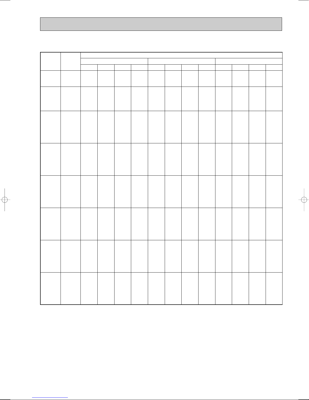
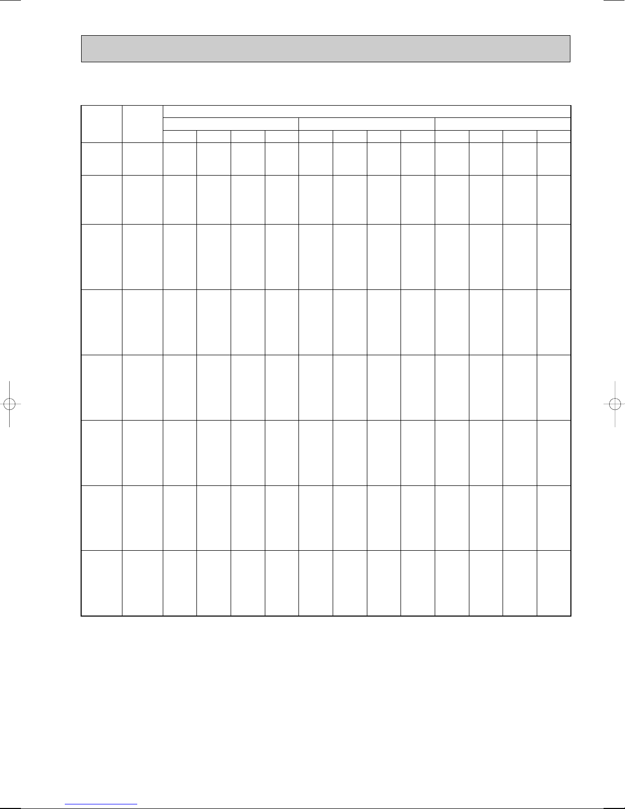
COOLING CAPACITY(4)
Outdoor intake air D.B.(°C)
35 40 45
Indoor
Intake air
D.B.(°C)
Indoor
Intake air
W.B.(°C)
20
20
22
22
22
24
24
24
24
26
26
26
26
27
27
27
27
28
28
28
28
30
30
30
30
32
32
32
32
16
18
16
18
20
16
18
20
22
16
18
20
22
16
18
20
22
16
18
20
22
16
18
20
22
16
18
20
22
CA SHC SHF P.C. CA SHC SHF P.C. CA SHC SHF P.C.
6070
5351
6773
6102
5307
7477
6853
6107
5228
8181
7604
6908
6082
8533
7980
7309
6509
8797
8355
7709
6936
8797
9106
8510
7789
8797
9388
9311
8643
0.69
0.57
0.77
0.65
0.53
0.85
0.73
0.61
0.49
0.93
0.81
0.69
0.57
0.97
0.85
0.73
0.61
1.00
0.89
0.77
0.65
1.00
0.97
0.85
0.73
1.00
1.00
0.93
0.81
0.69
0.57
0.77
0.65
0.53
0.85
0.73
0.61
0.49
0.93
0.81
0.69
0.57
0.97
0.85
0.73
0.61
1.00
0.89
0.77
0.65
1.00
0.97
0.85
0.73
1.00
1.00
0.93
0.81
0.69
0.57
0.77
0.65
0.53
0.85
0.73
0.61
0.49
0.93
0.81
0.69
0.57
0.97
0.85
0.73
0.61
1.00
0.89
0.77
0.65
1.00
0.97
0.85
0.73
1.00
1.00
0.93
0.81
3.34
3.42
3.34
3.42
3.50
3.34
3.42
3.50
3.59
3.34
3.42
3.50
3.59
3.34
3.42
3.50
3.59
3.34
3.42
3.50
3.59
3.34
3.42
3.50
3.59
3.34
3.42
3.50
3.59
8404
8982
8404
8982
9594
8404
8982
9594
10240
8404
8982
9594
10240
8404
8982
9594
10240
8404
8982
9594
10240
8404
8982
9594
10240
8404
8982
9594
10240
8797
9388
8797
9388
10012
8797
9388
10012
10670
8797
9388
10012
10670
8797
9388
10012
10670
8797
9388
10012
10670
8797
9388
10012
10670
8797
9388
10012
10670
5798
5120
6471
5838
5085
7143
6557
5852
5017
7815
7275
6620
5837
8151
7634
7003
6246
8404
7994
7387
6656
8404
8712
8155
7475
8404
8982
8922
8294
3.56
3.65
3.56
3.65
3.75
3.56
3.65
3.75
3.86
3.56
3.65
3.75
3.86
3.56
3.65
3.75
3.86
3.56
3.65
3.75
3.86
3.56
3.65
3.75
3.86
3.56
3.65
3.75
3.86
7989
8558
7989
8558
9159
7989
8558
9159
9792
7989
8558
9159
9792
7989
8558
9159
9792
7989
8558
9159
9792
7989
8558
9159
9792
7989
8558
9159
9792
5512
4878
6151
5562
4854
6790
6247
5587
4798
7430
6932
6320
5582
7749
7274
6686
5973
7989
7616
7052
6365
7989
8301
7785
7148
7989
8558
8518
7932
3.79
3.89
3.79
3.89
4.00
3.79
3.89
4.00
4.14
3.79
3.89
4.00
4.14
3.79
3.89
4.00
4.14
3.79
3.89
4.00
4.14
3.79
3.89
4.00
4.14
3.79
3.89
4.00
4.14
PLH-4AAK(H)
CA : Capacity (W) SHC : Sensible heat capacity (W)
P.C. : Power consumption (kW) SHF : Sensible heat factor
17
COOLING CAPACITY(5)
Outdoor intake air D.B.(°C)
20 25 30
Indoor
Intake air
D.B.(°C)
Indoor
Intake air
W.B.(°C)
20
20
22
22
22
24
24
24
24
26
26
26
26
27
27
27
27
28
28
28
28
30
30
30
30
32
32
32
32
16
18
16
18
20
16
18
20
22
16
18
20
22
16
18
20
22
16
18
20
22
16
18
20
22
16
18
20
22
12510
13319
12510
13319
14138
12510
13319
14138
14965
12510
13319
14138
14965
12510
13319
14138
14965
12510
13319
14138
14965
12510
13319
14138
14965
12510
13319
14138
14965
CA SHC SHF P.C. CA SHC SHF P.C. CA SHC SHF P.C.
7881
6793
8882
7858
6645
9883
8924
7776
6435
10883
9990
8907
7632
11384
10522
9472
8231
11884
11055
10038
8830
12510
12121
11169
10027
12510
13186
12300
11224
0.63
0.51
0.71
0.59
0.47
0.79
0.67
0.55
0.43
0.87
0.75
0.63
0.51
0.91
0.79
0.67
0.55
0.95
0.83
0.71
0.59
1.00
0.91
0.79
0.67
1.00
0.99
0.87
0.75
0.63
0.51
0.71
0.59
0.47
0.79
0.67
0.55
0.43
0.87
0.75
0.63
0.51
0.91
0.79
0.67
0.55
0.95
0.83
0.71
0.59
1.00
0.91
0.79
0.67
1.00
0.99
0.87
0.75
0.63
0.51
0.71
0.59
0.47
0.79
0.67
0.55
0.43
0.87
0.75
0.63
0.51
0.91
0.79
0.67
0.55
0.95
0.83
0.71
0.59
1.00
0.91
0.79
0.67
1.00
0.99
0.87
0.75
3.61
3.69
3.61
3.69
3.76
3.61
3.69
3.76
3.83
3.61
3.69
3.76
3.83
3.61
3.69
3.76
3.83
3.61
3.69
3.76
3.83
3.61
3.69
3.76
3.83
3.61
3.69
3.76
3.83
12167
12969
12167
12969
13806
12167
12969
13806
14679
12167
12969
13806
14679
12167
12969
13806
14679
12167
12969
13806
14679
12167
12969
13806
14679
12167
12969
13806
14679
7665
6614
8639
7652
6489
9612
8689
7593
6312
10585
9727
8698
7486
11072
10245
9250
8073
11559
10764
9802
8660
12167
11802
10907
9835
12167
12839
12011
11009
3.77
3.85
3.77
3.85
3.92
3.77
3.85
3.92
4.00
3.77
3.85
3.92
4.00
3.77
3.85
3.92
4.00
3.77
3.85
3.92
4.00
3.77
3.85
3.92
4.00
3.77
3.85
3.92
4.00
11720
12496
11720
12496
13313
11720
12496
13313
14170
11720
12496
13313
14170
11720
12496
13313
14170
11720
12496
13313
14170
11720
12496
13313
14170
11720
12496
13313
14170
7384
6373
8321
7373
6257
9259
8373
7322
6093
10196
9372
8387
7227
10665
9872
8920
7794
11134
10372
9452
8360
11720
11372
10517
9494
11720
12371
11582
10628
4.06
4.15
4.06
4.15
4.24
4.06
4.15
4.24
4.33
4.06
4.15
4.24
4.33
4.06
4.15
4.24
4.33
4.06
4.15
4.24
4.33
4.06
4.15
4.24
4.33
4.06
4.15
4.24
4.33
PLH-5AAK(H)
CA : Capacity (W) SHC : Sensible heat capacity (W)
P.C. : Power consumption (kW) SHF : Sensible heat factor
18
COOLING CAPACITY(6)
Outdoor intake air D.B.(°C)
35 40 45
Indoor
Intake air
D.B.(°C)
Indoor
Intake air
W.B.(°C)
20
20
22
22
22
24
24
24
24
26
26
26
26
27
27
27
27
28
28
28
28
30
30
30
30
32
32
32
32
16
18
16
18
20
16
18
20
22
16
18
20
22
16
18
20
22
16
18
20
22
16
18
20
22
16
18
20
22
11245
12001
11245
12001
12799
11245
12001
12799
13640
11245
12001
12799
13640
11245
12001
12799
13640
11245
12001
12799
13640
11245
12001
12799
13640
11245
12001
12799
13640
CA SHC SHF P.C. CA SHC SHF P.C. CA SHC SHF P.C.
7085
6120
7984
7080
6016
8884
8041
7040
5865
9783
9001
8064
6957
10233
9481
8575
7502
10683
9961
9087
8048
11245
10921
10111
9139
11245
11881
11135
10230
0.63
0.51
0.71
0.59
0.47
0.79
0.67
0.55
0.43
0.87
0.75
0.63
0.51
0.91
0.79
0.67
0.55
0.95
0.83
0.71
0.59
1.00
0.91
0.79
0.67
1.00
0.99
0.87
0.75
0.63
0.51
0.71
0.59
0.47
0.79
0.67
0.55
0.43
0.87
0.75
0.63
0.51
0.91
0.79
0.67
0.55
0.95
0.83
0.71
0.59
1.00
0.91
0.79
0.67
1.00
0.99
0.87
0.75
0.63
0.51
0.71
0.59
0.47
0.79
0.67
0.55
0.43
0.87
0.75
0.63
0.51
0.91
0.79
0.67
0.55
0.95
0.83
0.71
0.59
1.00
0.91
0.79
0.67
1.00
0.99
0.87
0.75
4.35
4.46
4.35
4.46
4.56
4.35
4.46
4.56
4.67
4.35
4.46
4.56
4.67
4.35
4.46
4.56
4.67
4.35
4.46
4.56
4.67
4.35
4.46
4.56
4.67
4.35
4.46
4.56
4.67
10743
11482
10743
11482
12264
10743
11482
12264
13090
10743
11482
12264
13090
10743
11482
12264
13090
10743
11482
12264
13090
10743
11482
12264
13090
10743
11482
12264
13090
6768
5856
7627
6774
5764
8487
7693
6745
5629
9346
8611
7726
6676
9776
9071
8217
7199
10206
9530
8708
7723
10743
10448
9689
8770
10743
11367
10670
9817
4.64
4.76
4.64
4.76
4.89
4.64
4.76
4.89
5.03
4.64
4.76
4.89
5.03
4.64
4.76
4.89
5.03
4.64
4.76
4.89
5.03
4.64
4.76
4.89
5.03
4.64
4.76
4.89
5.03
10212
10939
10212
10939
11708
10212
10939
11708
12518
10212
10939
11708
12518
10212
10939
11708
12518
10212
10939
11708
12518
10212
10939
11708
12518
10212
10939
11708
12518
6434
5579
7251
6454
5503
8068
7329
6439
5383
8885
8205
7376
6384
9293
8642
7844
6885
9702
9080
8313
7386
10212
9955
9249
8387
10212
10830
10186
9389
4.94
5.07
4.94
5.07
5.22
4.94
5.07
5.22
5.39
4.94
5.07
5.22
5.39
4.94
5.07
5.22
5.39
4.94
5.07
5.22
5.39
4.94
5.07
5.22
5.39
4.94
5.07
5.22
5.39
PLH-5AAK(H)
CA : Capacity (W) SHC : Sensible heat capacity (W)
P.C. : Power consumption (kW) SHF : Sensible heat factor
19
COOLING CAPACITY(7)
Outdoor intake air D.B.(°C)
20 25 30
Indoor
Intake air
D.B.(°C)
Indoor
Intake air
W.B.(°C)
20
20
22
22
22
24
24
24
24
26
26
26
26
27
27
27
27
28
28
28
28
30
30
30
30
32
32
32
32
16
18
16
18
20
16
18
20
22
16
18
20
22
16
18
20
22
16
18
20
22
16
18
20
22
16
18
20
22
14124
15038
14124
15038
15962
14124
15038
15962
16896
14124
15038
15962
16896
14124
15038
15962
16896
14124
15038
15962
16896
14124
15038
15962
16896
14124
15038
15962
16896
CA SHC SHF P.C. CA SHC SHF P.C. CA SHC SHF P.C.
8616
7369
9745
8572
7183
10875
9775
8460
6928
12005
10978
9737
8279
12570
11579
10375
8955
13135
12181
11014
9631
14124
13384
12291
10983
14124
14587
13568
12334
0.61
0.49
0.69
0.57
0.45
0.77
0.65
0.53
0.41
0.85
0.73
0.61
0.49
0.89
0.77
0.65
0.53
0.93
0.81
0.69
0.57
1.00
0.89
0.77
0.65
1.00
0.97
0.85
0.73
0.61
0.49
0.69
0.57
0.45
0.77
0.65
0.53
0.41
0.85
0.73
0.61
0.49
0.89
0.77
0.65
0.53
0.93
0.81
0.69
0.57
1.00
0.89
0.77
0.65
1.00
0.97
0.85
0.73
0.61
0.49
0.69
0.57
0.45
0.77
0.65
0.53
0.41
0.85
0.73
0.61
0.49
0.89
0.77
0.65
0.53
0.93
0.81
0.69
0.57
1.00
0.89
0.77
0.65
1.00
0.97
0.85
0.73
4.06
4.15
4.06
4.15
4.22
4.06
4.15
4.22
4.30
4.06
4.15
4.22
4.30
4.06
4.15
4.22
4.30
4.06
4.15
4.22
4.30
4.06
4.15
4.22
4.30
4.06
4.15
4.22
4.30
13737
14642
13737
14642
15587
13737
14642
15587
16573
13737
14642
15587
16573
13737
14642
15587
16573
13737
14642
15587
16573
13737
14642
15587
16573
13737
14642
15587
16573
8380
7175
9479
8346
7014
10578
9517
8261
6795
11677
10689
9508
8121
12226
11274
10132
8783
12776
11860
10755
9446
13737
13031
12002
10772
13737
14203
13249
12098
4.24
4.32
4.24
4.32
4.41
4.24
4.32
4.41
4.50
4.24
4.32
4.41
4.50
4.24
4.32
4.41
4.50
4.24
4.32
4.41
4.50
4.24
4.32
4.41
4.50
4.24
4.32
4.41
4.50
13232
14109
13232
14109
15031
13232
14109
15031
15998
13232
14109
15031
15998
13232
14109
15031
15998
13232
14109
15031
15998
13232
14109
15031
15998
13232
14109
15031
15998
8072
6913
9130
8042
6764
10189
9171
7966
6559
11247
10299
9169
7839
11777
10864
9770
8479
12306
11428
10371
9119
13232
12557
11574
10399
13232
13686
12776
11679
4.56
4.67
4.56
4.67
4.77
4.56
4.67
4.77
4.87
4.56
4.67
4.77
4.87
4.56
4.67
4.77
4.87
4.56
4.67
4.77
4.87
4.56
4.67
4.77
4.87
4.56
4.67
4.77
4.87
PLH-6AAK(H)
CA : Capacity (W) SHC : Sensible heat capacity (W)
P.C. : Power consumption (kW) SHF : Sensible heat factor
20
COOLING CAPACITY(8)
Outdoor intake air D.B.(°C)
35 40 45
Indoor
Intake air
D.B.(°C)
Indoor
Intake air
W.B.(°C)
20
20
22
22
22
24
24
24
24
26
26
26
26
27
27
27
27
28
28
28
28
30
30
30
30
32
32
32
32
16
18
16
18
20
16
18
20
22
16
18
20
22
16
18
20
22
16
18
20
22
16
18
20
22
16
18
20
22
12696
13549
12696
13549
14451
12696
13549
14451
15401
12696
13549
14451
15401
12696
13549
14451
15401
12696
13549
14451
15401
12696
13549
14451
15401
12696
13549
14451
15401
CA SHC SHF P.C. CA SHC SHF P.C. CA SHC SHF P.C.
7745
6639
8760
7723
6503
9776
8807
7659
6314
10792
9891
8815
7546
11300
10433
9393
8162
11808
10975
9971
8778
12696
12059
11127
10010
12696
13143
12283
11242
0.61
0.49
0.69
0.57
0.45
0.77
0.65
0.53
0.41
0.85
0.73
0.61
0.49
0.89
0.77
0.65
0.53
0.93
0.81
0.69
0.57
1.00
0.89
0.77
0.65
1.00
0.97
0.85
0.73
0.61
0.49
0.69
0.57
0.45
0.77
0.65
0.53
0.41
0.85
0.73
0.61
0.49
0.89
0.77
0.65
0.53
0.93
0.81
0.69
0.57
1.00
0.89
0.77
0.65
1.00
0.97
0.85
0.73
0.61
0.49
0.69
0.57
0.45
0.77
0.65
0.53
0.41
0.85
0.73
0.61
0.49
0.89
0.77
0.65
0.53
0.93
0.81
0.69
0.57
1.00
0.89
0.77
0.65
1.00
0.97
0.85
0.73
4.89
5.01
4.89
5.01
5.13
4.89
5.01
5.13
5.25
4.89
5.01
5.13
5.25
4.89
5.01
5.13
5.25
4.89
5.01
5.13
5.25
4.89
5.01
5.13
5.25
4.89
5.01
5.13
5.25
12129
12963
12129
12963
13847
12129
12963
13847
14779
12129
12963
13847
14779
12129
12963
13847
14779
12129
12963
13847
14779
12129
12963
13847
14779
12129
12963
13847
14779
7399
6352
8369
7389
6231
9339
8426
7339
6059
10310
9463
8446
7242
10795
9982
9000
7833
11280
10500
9554
8424
12129
11537
10662
9606
12129
12574
11770
10789
5.22
5.35
5.22
5.35
5.50
5.22
5.35
5.50
5.65
5.22
5.35
5.50
5.65
5.22
5.35
5.50
5.65
5.22
5.35
5.50
5.65
5.22
5.35
5.50
5.65
5.22
5.35
5.50
5.65
11530
12351
11530
12351
13219
11530
12351
13219
14133
11530
12351
13219
14133
11530
12351
13219
14133
11530
12351
13219
14133
11530
12351
13219
14133
11530
12351
13219
14133
7033
6052
7956
7040
5948
8878
8028
7006
5795
9801
9016
8063
6925
10262
9510
8592
7491
10723
10004
9121
8056
11530
10992
10178
9187
11530
11981
11236
10317
5.55
5.70
5.55
5.70
5.87
5.55
5.70
5.87
6.06
5.55
5.70
5.87
6.06
5.55
5.70
5.87
6.06
5.55
5.70
5.87
6.06
5.55
5.70
5.87
6.06
5.55
5.70
5.87
6.06
PLH-6AAK(H)
CA : Capacity (W) SHC : Sensible heat capacity (W)
P.C. : Power consumption (kW) SHF : Sensible heat factor
21
Refrigerant piping length(one way)
5m
1.00
1.00
1.00
1.00
10m
0.981
0.989
0.981
0.975
15m
0.968
0.980
0.968
0.955
20m
0.952
0.970
0.952
0.935
25m
0.940
0.960
0.940
0.918
30m
0.925
0.950
0.925
0.900
35m
0.913
0.940
0.913
0.884
40m
0.900
0.930
0.900
0.869
45m
0.886
0.920
0.886
0.855
50m
0.874
0.910
0.874
0.840
Service Ref.
PLH-3AAK(H)
PLH-4AAK(H)
PLH-5AAK(H)
PLH-6AAK(H)
2) HEATING CAPACITY
P.C.
3.38
3.64
3.90
3.75
4.04
4.33
3.75
4.04
4.33
5.35
5.76
6.18
CA
10752
10340
10044
13312
12802
12435
13312
12802
12435
20608
19818
19250
P.C.
3.10
3.34
3.58
3.44
3.70
3.97
3.44
3.70
3.97
4.90
5.28
5.66
CA
9595
9235
8928
11880
11434
11054
11880
11434
11054
18391
17700
17112
P.C.
2.83
3.05
3.27
3.14
3.39
3.63
3.14
3.39
3.63
4.48
4.83
5.17
CA
8516
8198
7895
10543
10150
9774
10543
10150
9774
16322
15713
15131
P.C.
2.58
2.78
2.97
2.86
3.09
3.30
2.86
3.09
3.30
4.09
4.40
4.71
CA
7514
7231
6944
9303
8953
8597
9303
8953
8597
14402
13859
13309
P.C.
2.34
2.53
2.69
2.60
2.80
2.99
2.60
2.80
2.99
3.71
4.00
4.26
CA
6593
6334
6077
8163
7842
7524
10988
10557
10128
12636
12140
11647
P.C.
2.12
2.29
2.43
2.35
2.54
2.69
2.35
2.54
2.69
3.36
3.62
3.84
CA
5752
5508
5293
7122
6820
6554
9587
9180
8822
11026
10557
10146
-10
Outdoor intake air W.B.(°C)
-5 0 5 10 15
Indoor
intake air
D.B.(°C)
15
20
25
15
20
25
15
20
25
15
20
25
Service Ref.
PLH-3AAK(H)
PLH-4AAK(H)
PLH-5AAK(H)
PLH-6AAK(H)
Refrigerant piping length(one way)
5m
1.00
1.00
1.00
1.00
10m
1.00
1.00
1.00
1.00
15m
1.00
1.00
1.00
1.00
20m
1.00
1.00
1.00
1.00
25m
1.00
1.00
1.00
1.00
30m
1.00
1.00
1.00
1.00
35m
0.998
0.998
0.998
0.998
40m
0.995
0.995
0.995
0.995
45m
0.993
0.993
0.993
0.993
50m
0.990
0.990
0.990
0.990
Service Ref.
PLH-3AAK(H)
PLH-4AAK(H)
PLH-5AAK(H)
PLH-6AAK(H)
1.4
1.2
1.0
0.8
0.6
1.4
1.2
1.0
0.8
0.6
0.4
-12-10 -5 0 5 10 15
OUTDOOR WB(°C)
INDOOR DB (°C)
INDOOR DB (°C)
15
20
25
25
20
15
TOTAL INPUT (RATIO) CAPACITY (RATIO)
1.4
1.2
1.0
0.8
0.6
1.4
1.2
1.0
0.8
0.6
0.4
-5 5 15 253546
OUTDOOR DB(°C)
TOTAL INPUT (RATIO) CAPACITY (RATIO)
INDOOR WB(°C)
INDOOR WB(°C)
22
20
18
16
22
20
18
16
Note C A:Capacity (W)
P.C.:Power consumption (kW)
Cooling capacity correction factors
Heating capacity correction factors
2. PERFORMANCE CURVE
PLH-3AAK(H) / PLH-4AAK(H) / PLH-5AAK(H) / PLH-6AAK(H)
Cooling
22
Heating
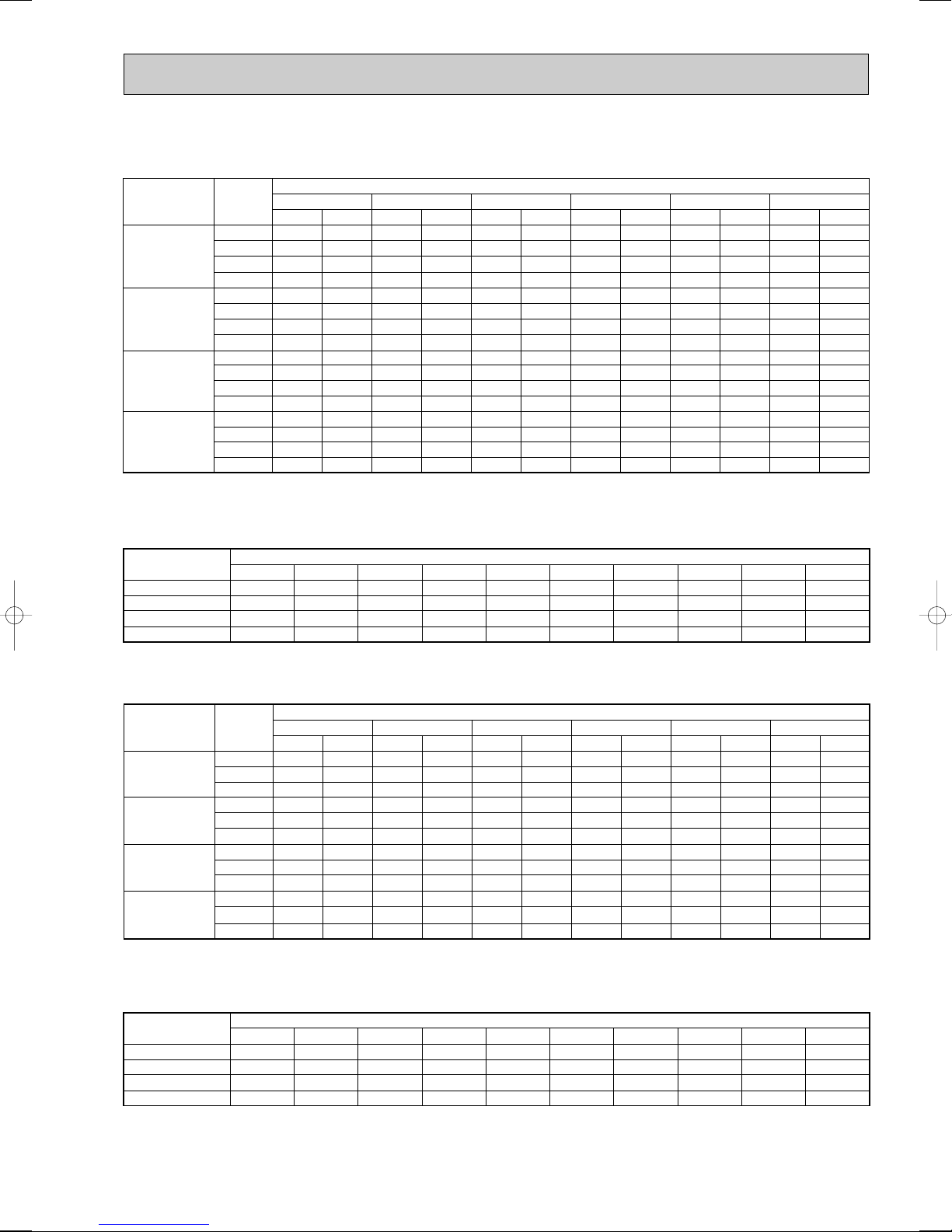
3. PERFORMANCE DATA [60Hz]
Refrigerant piping length(one way)
5m
1.00
1.00
1.00
1.00
10m
0.981
0.989
0.981
0.975
15m
0.968
0.980
0.968
0.955
20m
0.952
0.970
0.952
0.935
25m
0.940
0.960
0.940
0.918
30m
0.925
0.950
0.925
0.900
35m
0.913
0.940
0.913
0.884
40m
0.900
0.930
0.900
0.869
45m
0.886
0.920
0.886
0.855
50m
0.874
0.910
0.874
0.840
Service Ref.
PLH-3AAK
PLH-4AAK
PLH-5AAK
PLH-6AAK
P.C.
3.79
4.08
4.38
4.58
4.93
5.28
6.54
7.04
7.56
7.28
7.84
8.41
CA
11904
11448
11120
15488
14894
14468
21120
20310
19728
22401
21541
20924
P.C.
3.48
3.75
4.02
4.20
4.52
4.85
6.00
6.46
6.93
6.68
7.19
7.71
CA
10623
10224
9885
13822
13302
12861
18848
18140
17537
19990
19239
18600
P.C.
3.18
3.43
3.67
3.84
4.13
4.43
5.49
5.91
6.33
6.11
6.58
7.05
CA
9428
9077
8741
12267
11809
11372
16727
16104
15507
17741
17080
16447
P.C.
2.90
3.12
3.34
3.50
3.77
4.03
5.00
5.39
5.76
5.56
6.00
6.41
CA
8319
8006
7688
10824
10416
10003
14760
14204
13640
15655
15065
14467
P.C.
2.63
2.84
3.02
3.17
3.42
3.65
4.54
4.89
5.21
5.05
5.44
5.80
CA
7299
7013
6728
9497
9124
8753
12950
12442
11936
13735
13196
12660
P.C.
2.38
2.57
2.72
2.87
3.09
3.29
4.11
4.43
4.70
4.57
4.93
5.23
CA
6369
6098
5861
8286
7934
7625
11299
10820
10398
11984
11475
11028
-10
Outdoor intake air W.B.(°C)
-5 0 5 10 15
Indoor
intake air
D.B.(°C)
15
20
25
15
20
25
15
20
25
15
20
25
Service Ref.
PLH-3AAK
PLH-4AAK
PLH-5AAK
PLH-6AAK
Refrigerant piping length(one way)
5m
1.00
1.00
1.00
1.00
10m
1.00
1.00
1.00
1.00
15m
1.00
1.00
1.00
1.00
20m
1.00
1.00
1.00
1.00
25m
1.00
1.00
1.00
1.00
30m
1.00
1.00
1.00
1.00
35m
0.998
0.998
0.998
0.998
40m
0.995
0.995
0.995
0.995
45m
0.993
0.993
0.993
0.993
50m
0.990
0.990
0.990
0.990
Service Ref.
PLH-3AAK
PLH-4AAK
PLH-5AAK
PLH-6AAK
1) COOLING CAPACITY(1)
PLH-3AAK / PLH-4AAK / PLH-5AAK / PLH-6AAK
Indoor
Service Ref.
PLH-3AAK
PLH-4AAK
PLH-5AAK
PLH-6AAK
Note C A:Capacity (W)
P.C.:Power consumption (kW)
Cooling capacity correction factors
intake air
W.B.(°C)
16
18
20
22
16
18
20
22
16
18
20
22
16
18
20
22
CA
8071
8593
9121
9655
11047
11762
12485
13215
13115
13964
14822
15690
15334
16327
17330
18345
20
P.C.
2.95
3.01
3.07
3.12
3.52
3.59
3.66
3.73
4.47
4.56
6.65
4.74
4.93
5.03
5.12
5.22
CA
7850
8367
8907
9470
10744
11452
12191
12962
12756
13596
14474
15389
14915
15897
16923
17993
Outdoor intake air D.B.(°C)
25 30 35 40 45
P.C.
3.08
3.14
3.20
3.26
3.67
3.74
3.82
3.89
4.66
4.76
4.85
4.95
5.14
5.24
5.35
5.45
CA
7561
8062
8589
9142
10350
11035
11756
12513
12287
13101
13957
14856
14367
15318
16319
17370
P.C.
3.31
3.39
3.46
3.53
3.95
4.04
4.13
4.22
5.02
5.14
5.25
5.36
5.53
5.66
5.78
5.91
CA
7255
7742
8258
8800
9930
10597
11303
12045
11789
12581
13419
14301
13785
14711
15689
16721
P.C.
3.55
3.64
3.72
3.81
4.23
4.34
4.44
4.55
5.38
5.51
5.65
5.78
5.93
6.08
6.22
6.37
CA
6931
7408
7912
8445
9486
10139
10830
11559
11263
12037
12858
13723
13168
14074
15034
16046
P.C.
3.79
3.89
3.99
4.10
4.52
4.64
4.76
4.89
5.74
5.89
6.05
6.22
6.33
6.49
6.67
6.86
CA
6589
7058
7554
8076
9018
9660
10339
11054
10707
11469
12275
13124
12518
13410
14352
15345
P.C.
4.03
4.14
4.26
4.40
4.81
4.93
5.08
5.25
6.11
6.27
6.46
6.67
6.73
6.91
7.12
7.35
2) HEATING CAPACITY
Note C A:Capacity (W)
P.C.:Power consumption (kW)
Heating capacity correction factors
23
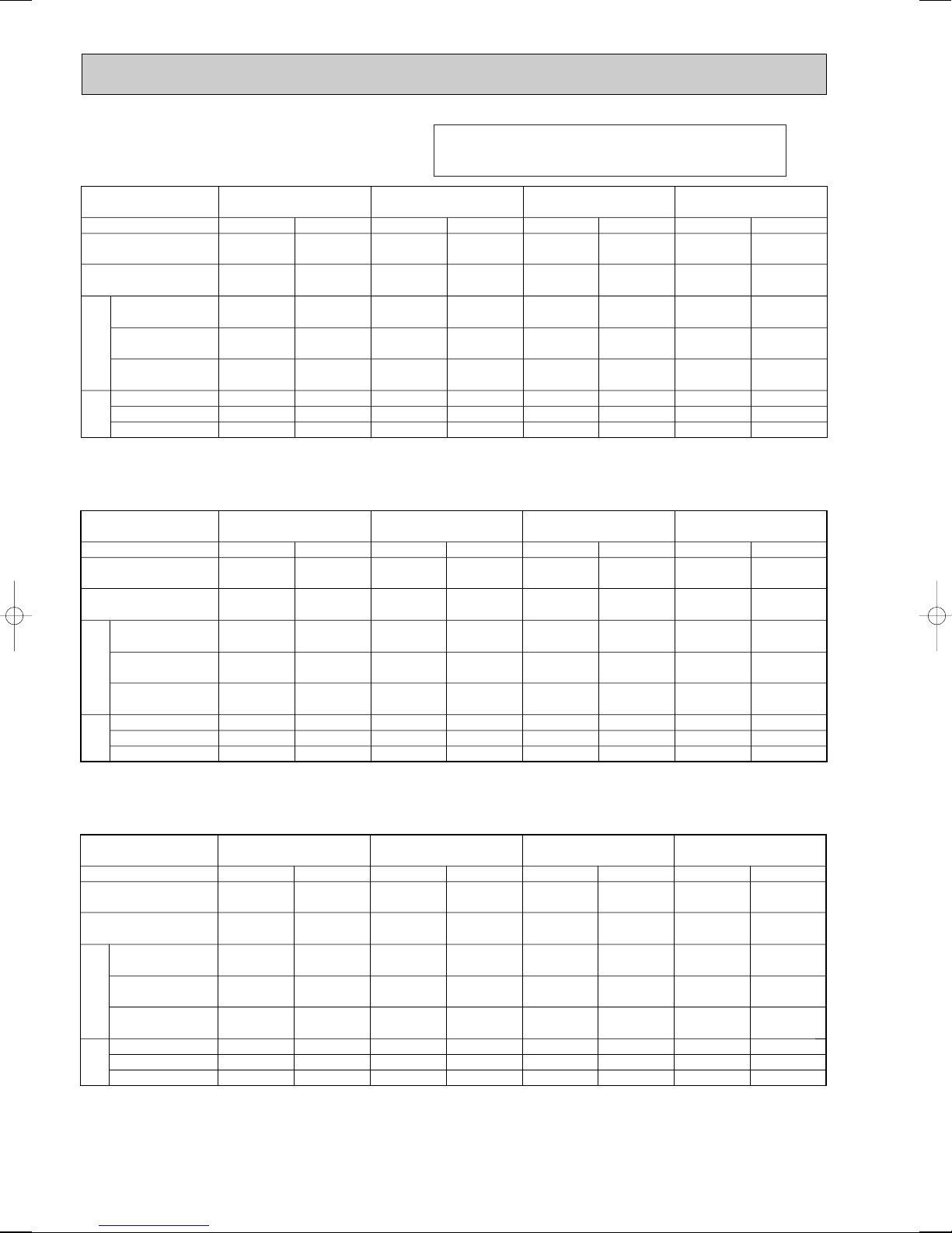
Input (kW)
Current (A)
Starting current (A)
Input (kW)
Current (A)
Starting current (A)
Mode
Capacity (W)
Total Input (kW)
IndoorOutdoor
PLH-3AAK(H)Service Ref.
Cool
7,500
3.28
0.15
0.78
1.0
3.13
14.67/5.23
54/34
Heat
8,200
[9,950]
3.07
[4.83]
0.15
[1.91]
0.78
[8.69]
1.0
[8.9]
2.92
13.68/4.88
54/34
PLH-4AAK(H)
Cool
9,500
3.41
0.24
1.25
2.0
3.17
5.29
37
Heat
10,200
[12,400]
3.40
[5.58]
0.24
[2.42]
1.25
[11.02]
2.0
[11.8]
3.16
5.28
37
PLH-5AAK(H)
Cool
12,200
4.47
0.28
1.43
2.0
4.19
7.32
60
Heat
13,600
[16,120]
4.41
[6.93]
0.28
[2.80]
1.43
[12.74]
2.0
[13.3]
4.13
7.21
60
PLH-6AAK(H)
Cool
13,800
4.96
0.32
1.64
2.0
4.64
8.10
68
Heat
15,700
[18,220]
4.88
[7.40]
0.32
[2.84]
1.64
[12.93]
2.0
[13.3]
4.56
7.96
68
4. ELECTRICAL DATA
Input (kW)
Current (A)
Starting current (A)
Input (kW)
Current (A)
Starting current (A)
Mode
Capacity (W)
Total Input (kW)
IndoorOutdoor
PLH-3AAK(H)Service Ref.
Cool
7,600
3.30
0.16
0.79
1.0
3.14
14.22/5.21
56/36
Heat
8,300
[10,200]
3.09
[5.02]
0.16
[2.09]
0.79
[9.09]
1.0
[9.3]
2.93
13.27/4.86
56/36
PLH-4AAK(H)
Cool
9,600
3.44
0.25
1.25
2.0
3.19
5.23
39
Heat
10,300
[12,700]
3.43
[5.82]
0.25
[2.64]
1.25
[11.49]
2.0
[12.2]
3.18
5.22
39
PLH-5AAK(H)
Cool
12,300
4.49
0.29
1.43
2.0
4.20
7.05
63
Heat
13,800
[16,560]
4.44
[7.20]
0.29
[3.05]
1.43
[13.28]
2.0
[13.9]
4.15
6.97
63
PLH-6AAK(H)
Cool
13,900
5.02
0.33
1.64
2.0
4.69
7.87
71
Heat
15,900
[18,660]
4.90
[7.66]
0.33
[3.09]
1.64
[13.46]
2.0
[13.8]
4.57
7.67
71
Input (kW)
Current (A)
Starting current (A)
Input (kW)
Current (A)
Starting current (A)
Mode
Capacity (W)
Total Input (kW)
IndoorOutdoor
PLH-3AAK(H)Service Ref.
Cool
7,700
3.32
0.17
0.81
1.0
3.15
13.82/5.16
58/37
Heat
8,400
[10,500]
3.11
[5.21]
0.17
[2.27]
0.81
[9.47]
1.0
[9.7]
2.94
12.89/4.81
58/37
PLH-4AAK(H)
Cool
9,700
3.46
0.26
1.25
2.0
3.20
5.24
40
Heat
10,400
[13,000]
3.45
[6.05]
0.26
[2.86]
1.25
[11.93]
2.0
[12.7]
3.19
5.22
40
PLH-5AAK(H)
Cool
12,400
4.51
0.30
1.43
2.0
4.21
6.89
65
Heat
14,000
[17,000]
4.46
[7.46]
0.30
[3.30]
1.43
[13.77]
2.0
[14.3]
4.16
6.81
65
PLH-6AAK(H)
Cool
14,000
5.07
0.34
1.64
2.0
4.73
7.74
74
Heat
16,100
[19,100]
4.92
[7.92]
0.34
[3.34]
1.64
[13.94]
2.0
[14.3]
4.58
7.50
74
Indoor unit …220V 50Hz 1phase
Outdoor unit…220V 50Hz 1phase / 380V 50Hz 3phase
Indoor unit …230V 50Hz 1phase
Outdoor unit…230V 50Hz 1phase / 400V 50Hz 3phase
Refer to 3SPECIFICATIONS regarding the combination of
PUH-3NKA or PUH-4/5/6TKSA.
Indoor unit …240V 50Hz 1phase
Outdoor unit…240V 50Hz 1phase / 415V 50Hz 3phase
24
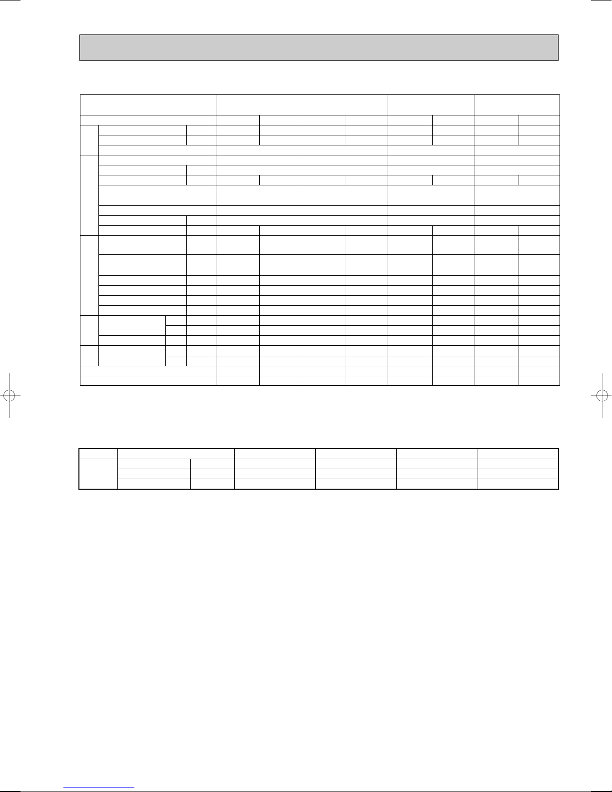
5. STANDARD OPERATION DATA
PLH-3AAK(H) PLH-4AAK(H) PLH-5AAK(H) PLH-6AAK(H)Service Ref.
Mode
Capacity
Input
Total
Indoor unit Service Ref.
Phase, Hz
Volts
Amperes
Outdoor unit Service Ref.
Phase,Hz
Electrical circuitRefrigerant circuit
Volts
Amperes
Discharge pressure
Suction pressure
Discharge temperature
Condensing temperature
Suction temperature
Ref. pipe length
Intake air
temperature
side
Indoor
Discharge air temperature
Intake air
side
temperature
Outdoor
SHF
BF
D.B.
W.B.
D.B.
D.B.
W.B.
MPa
(kgf/F)
MPa
(kgf/F)
W
kW
°C
°C
°C
°C
°C
°C
°C
°C
V
A
V
A
m
Cooling
7,700
3.32
PLH-3AAK(H)
0.81 0.81
PUH-3VKA.TH
PUH-3YKA.TH
1/3,50
240/415
13.82/5.16
2.01
(20.5)
0.51
(5.2)
84
41
3.9
5
27
19
13.2
35
24
0.74
0.12
1, 50
240
Heating
8,400
3.11
12.89/4.81
1.89
(19.3)
0.42
(4.3)
77
—
-2.0
5
20
15
42.8
7
6
—
—
Cooling
9,700
3.46
PLH-4AAK(H)
1.25 1.25
PUH-4YKSA.TH
5.24
1.81
(18.5)
0.49
(5.0)
80
41
10.5
5
27
19
13.7
35
24
0.79
0.08
Heating
10,400
1, 50
240
3,50
415
3.45
5.22
1.73
(17.6)
0.36
(3.7)
75
—
1.0
5
20
15
39.9
7
6
—
—
Cooling
12,400
4.51
PLH-5AAK(H)
1,50
240
1.43 1.43
PUH-5YKSA.TH
3,50
415
6.89
1.85
(18.9)
0.44
(4.5)
76
46
4.0
5
27
19
12.5
35
24
0.73
0.10
Heating
14,000
4.46
6.81
1.94
(19.8)
0.36
(3.7)
81
—
1.1
5
20
15
45.5
7
6
—
—
Cooling
14,000
5.07
PLH-6AAK(H)
1.64 1.64
PUH-6YKSA.TH
7.74
1.90
(19.4)
0.42
(4.3)
74
39
4.6
5
27
19
11.2
35
24
0.71
0.06
Heating
16,100
1,50
240
3,50
415
4.92
7.50
2.01
(20.5)
0.37
(3.8)
76
—
0.3
5
20
15
49.8
7
6
—
—
The unit of pressure has been changed to Mpa based on the international SI system.
FF
The conversion factor is : 1(Mpa)=10.2(kgf/
)
6. OUTLET AIR SPEED AND COVERAGE RANGE
PLH-5AAK(H)
30(1,060)
5.2
7.9
Standard
Air flow
Air speed
Coverage range
K/
mim(CFM)
m/W
m
PLH-3AAK(H)
20(705)
4.0
5.7
PLH-4AAK(H)
28(990)
4.9
7.4
wThe air coverage range is the value up to the position where the air speed is 0.25m/sec.
When air is blown out horizontally from the unit at the Hi notch position.
The coverage range should be used only as a general guideline since it varies according to the size of the room and the
furniture inside the room.
PLH-6AAK(H)
30(1,060)
6.6
8.9
25
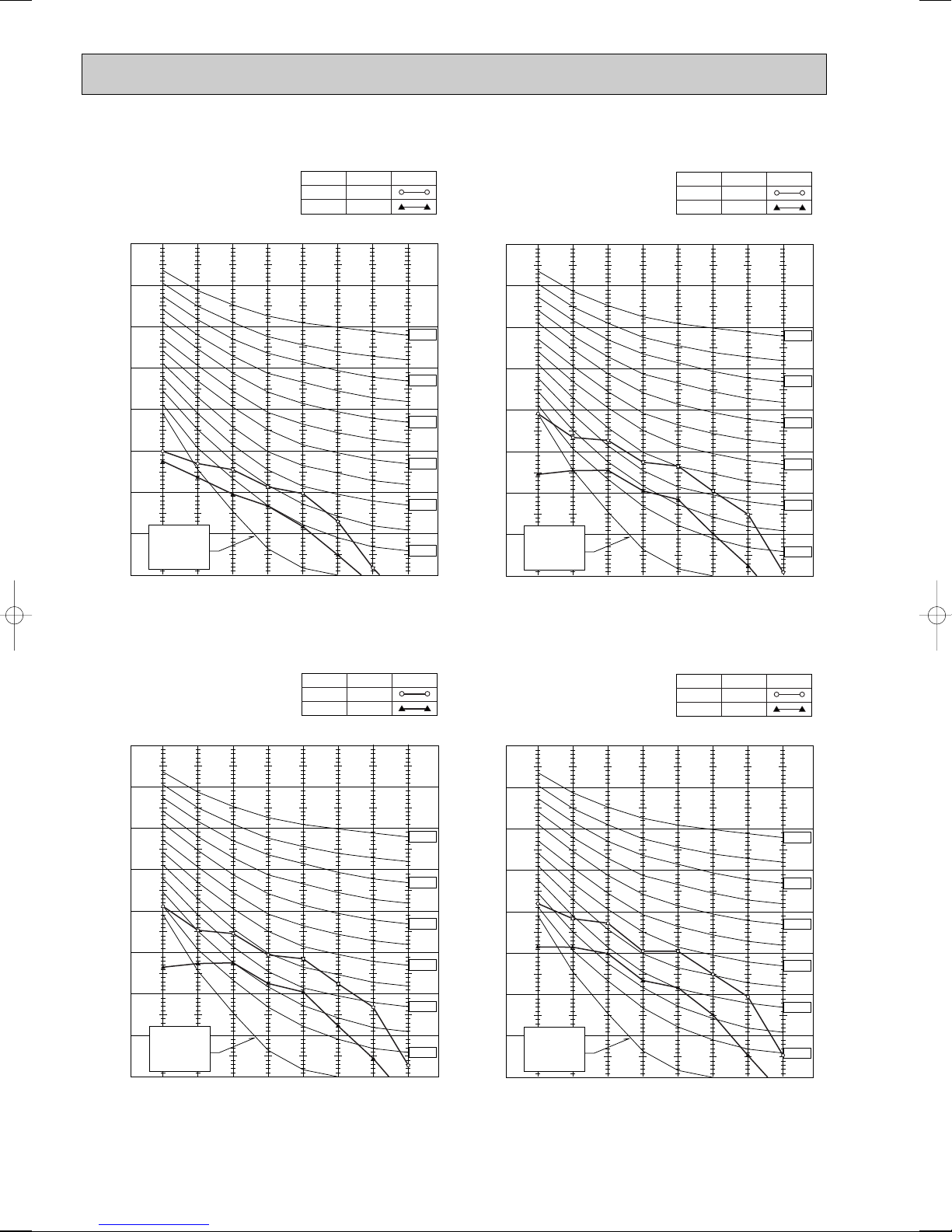
90
80
70
60
50
40
30
20
10
63 125 250 500 1000 2000 4000 8000
APPROTIMATE
TERESHOLD OF
REARING FOR
CONTINUOUS
NOISE
NC-60
NC-50
NC-40
NC-30
NC-20
NC-70
OCTAVE BAND SOUND PRESSURE LEVEL,
BAND CENTER FREQUENCIES, Hz
(0dB=0.0002 µ BAR)
PLH-4AAK(H)
High
NOTCH
Low
41
SPL(dB)
33
LINE
90
80
70
60
50
40
30
20
10
63 125 250 500 1000 2000 4000 8000
APPROTIMATE
TERESHOLD OF
REARING FOR
CONTINUOUS
NOISE
NC-60
NC-50
NC-40
NC-30
NC-20
NC-70
OCTAVE BAND SOUND PRESSURE LEVEL, (0dB=0.0002 µ BAR)
BAND CENTER FREQUENCIES, Hz
PLH-3AAK(H)
High
Low
34
SPL(dB)28LINE
NOTCH
7. NOISE CRITERION CURVES
90
80
70
60
50
40
30
20
10
63 125 250 500 1000 2000 4000 8000
APPROTIMATE
TERESHOLD OF
REARING FOR
CONTINUOUS
NOISE
NC-60
NC-50
NC-40
NC-30
NC-20
NC-70
OCTAVE BAND SOUND PRESSURE LEVEL,
BAND CENTER FREQUENCIES, Hz
(0dB=0.0002 µ BAR)
PLH-6AAK(H)
High
NOTCH
Low
45
SPL(dB)
37
LINE
90
80
70
60
50
40
30
20
10
63 125 250 500 1000 2000 4000 8000
APPROTIMATE
TERESHOLD OF
REARING FOR
CONTINUOUS
NOISE
NC-60
NC-50
NC-40
NC-30
NC-20
NC-70
OCTAVE BAND SOUND PRESSURE LEVEL, (0dB=0.0002 µ BAR)
BAND CENTER FREQUENCIES, Hz
PLH-5AAK(H)
High
NOTCH
Low
43
SPL(dB)
35
LINE
26
 Loading...